uk protective marking: uk hpr1000 gda · edg emergency diesel generator ... fmea failure modes and...
TRANSCRIPT

UK HPR1000
GDA
Preliminary Safety Report Chapter 12
Design Basis Conditions Analysis
UK Protective Marking: Not Protectively Marked
Rev: 000 Page: 2 / 34
UK Protective Marking: Not Protectively Marked
DISTRIBUTION LIST
Recipients Cross Box
GNS Executive ☐
GNS all staff ☐
GNS and BRB all staff
CGN
EDF
Regulators ☒
Public ☒
☒
☒
☒

UK HPR1000
GDA
Preliminary Safety Report Chapter 12
Design Basis Conditions Analysis
UK Protective Marking: Not Protectively Marked
Rev: 000 Page: 3 / 34
UK Protective Marking: Not Protectively Marked
SENSITIVE INFORMATION RECORD
Section
Number Section Title Page Content Category

UK HPR1000
GDA
Preliminary Safety Report Chapter 12
Design Basis Conditions Analysis
UK Protective Marking: Not Protectively Marked
Rev: 000 Page: 4 / 34
UK Protective Marking: Not Protectively Marked
Table of Contents
12.1 List of Abbreviations and Acronyms ............................................. 6
12.2 Introduction ................................................................................. 8
12.3 Fault Identification and Fault Grouping Methodology ................... 8
12.3.1 Scope of Fault Identification......................................................... 8
12.3.2 Fault Identification and Fault Grouping Methodology ................... 9
12.3.3 Fault List ................................................................................... 10
12.3.3.1 Safety Analysis Conditions ......................................................... 10
12.3.3.2 DBC-1: Normal Operation ......................................................... 11
12.3.3.3 DBC-2: Anticipated Operating Occurrences ................................ 11
12.3.3.4 DBC-3: Infrequent Faults ........................................................... 13
12.3.3.5 DBC-4: Limiting Accidents ........................................................ 14
12.4 Fault Schedule Methodology ...................................................... 16
12.5 DBC Analysis Methodology and Assumptions ............................ 17
12.5.1 Analysis Rules ........................................................................... 17
12.5.2 Main Assumptions ..................................................................... 20
12.6 Design Basis Analysis ................................................................ 21
12.6.1 Examples of Assessment ............................................................ 21
12.6.2 Uncontrolled Rod Cluster Control Assembly Bank Withdrawal at
Power ................................................................................................. 21
12.6.2.1 Description ................................................................................ 21
12.6.2.2 Typical transient sequence .......................................................... 22
12.6.2.3 Acceptance criteria ..................................................................... 22

UK HPR1000
GDA
Preliminary Safety Report Chapter 12
Design Basis Conditions Analysis
UK Protective Marking: Not Protectively Marked
Rev: 000 Page: 5 / 34
UK Protective Marking: Not Protectively Marked
12.6.2.4 Methods and assumptions ........................................................... 22
12.6.2.5 Results and conclusion ............................................................... 22
12.6.3 Steam Line Break (SLB) ............................................................ 24
12.6.3.1 Description ................................................................................ 24
12.6.3.2 Typical transient sequence .......................................................... 25
12.6.3.3 Acceptance criteria ..................................................................... 25
12.6.3.4 Methods and assumptions ........................................................... 25
12.6.3.5 Results and conclusion ............................................................... 26
12.6.4 LB-LOCA at Full-power Conditions ........................................... 28
12.6.4.1 Description ................................................................................ 28
12.6.4.2 Typical transient sequence .......................................................... 28
12.6.4.3 Acceptance criteria ..................................................................... 29
12.6.4.4 Methods and assumptions in HPR1000 (FCG3)........................... 29
12.6.4.5 Results and conclusion in HPR1000 (FCG3) ............................... 31
12.7 Radiological Consequences of Design Basis Events .................... 34
12.8 References ................................................................................. 34

UK HPR1000
GDA
Preliminary Safety Report Chapter 12
Design Basis Conditions Analysis
UK Protective Marking: Not Protectively Marked
Rev: 000 Page: 6 / 34
UK Protective Marking: Not Protectively Marked
12.1 List of Abbreviations and Acronyms
AAD Startup and Shutdown Feedwater system[SSFS]
ACC Accumulator
ARE Main Feedwater Flow Control System [MFFCS]
ASG Emergency Feedwater System[EFS]
CPR1000 Chinese Pressurized Reactor
DBA Design Basis Analysis
DBC Design Basis Condition
DN Nominal Diameter
DNB Departure from Nucleate Boiling
DNBR Departure from Nucleate Boiling Ratio
ECCS Emergency Core Cooling System
EDG Emergency Diesel Generator
EOC End of Cycle
FC1 Safety Category 1 Function
FC2 Safety Category 2 Function
FCG Unit3 Fangchenggang Nuclear Power Plant Unit 3
FMEA Failure Modes and Effects Analysis
FP Full Power
GDA Generic Design Assessment
HPR1000 Hua-long Pressurized Reactor
HPR1000 (FCG3) Hua-long Pressurized Reactor under construction at Fangchenggang
nuclear power plant unit 3
I&C Instrumentation and Control
IRWST In-containment Refuelling Water Storage Tank
LB-LOCA Large Break(Loss of Coolant Accident)
LHSI Low Head Safety Injection
LOCA Loss of Coolant Accident

UK HPR1000
GDA
Preliminary Safety Report Chapter 12
Design Basis Conditions Analysis
UK Protective Marking: Not Protectively Marked
Rev: 000 Page: 7 / 34
UK Protective Marking: Not Protectively Marked
LOOP Loss of Off-Site Power
MHSI Medium Head Safety Injection
MSIV Main Steam Isolation Valve
NNSA National Nuclear Safety Administration
PCSR Pre-Construction Safety Report
PCT Peaking Cladding Temperature
PIE Postulated Initiating Events
PSA Probabilistic Safety Assessment
PSAR Preliminary Safety Analysis Report
PSR Preliminary Safety Report
PTR Fuel Pool Cooling and Treatment System[FPCTS]
RBS Emergency Boration System[EBS]
RCCA Rod Cluster Control Assembly
RCP Reactor Coolant System[RCS]
RCPB Reactor Coolant Pressure Boundary
RCV Chemical and Volume Control System[CVCS]
RHR Residual Heat Removal
RIS Safety Injection System[SIS]
SFC Single Failure Criterion
SG Steam Generator
SLB Steam Line Break
SSCs Structures, Systems and Components
UK HPR1000 The UK version of the Hua-long Pressurized Reactor
URWP Uncontrolled RCCA bank Withdrawal at Power
VDA Main Steam Relief Train[MSRT]
WR Wide Range
System codes (XXX) and system abbreviations (YYY) are provided for completeness in
the format (XXX [YYY]), e.g. Emergency Feedwater System (ASG [EFS]).

UK HPR1000
GDA
Preliminary Safety Report Chapter 12
Design Basis Conditions Analysis
UK Protective Marking: Not Protectively Marked
Rev: 000 Page: 8 / 34
UK Protective Marking: Not Protectively Marked
12.2 Introduction
This chapter supports the following high level objective: the UK version of the Hua- long
Pressurized Reactor (UK HPR1000) design will be developed in an evolutionary manner,
using robust design processes, building on relevant good international practice, to achieve
a strong safety and environmental performance.
This chapter will demonstrate the following:
a) All initiating faults with the potential to lead to significant radiation exposure or
release of radioactive material will be identified in the Fault Schedule;
b) The Design Basis Analysis (DBA) provides a robust demonstration of the fault
tolerance of the engineering design and the effectiveness of the safety measures.
In addition, this chapter includes the initiating events list for DBA required to be
considered for the assessment of Hua- long Pressurized Reactor under construction at
Fangchenggang nuclear power plant unit 3 (HPR1000 (FCG3)), along with example
analysis results for three key initiating events.
The scope of fault identification for the DBA and a summary of the methodology of fault
identification and fault grouping required for the Hua-long Pressurized Reactor
(HPR1000) safety case are addressed in sub-chapter 12.3.
In sub-chapter 12.4, an outline of the process to be followed to produce the fault schedule
for UK HPR1000 and key elements to be included in the resultant fault schedule are
discussed.
In sub-chapter 12.5, the DBA methodology and assumptions, analysis rules and main
assumptions considered in the DBA for HPR1000 are briefly described.
In sub-chapter 12.6, the key requirements on the DBA, a discussion on the scope of
assessment and a brief summary of the DBA results are presented. As the detailed
analysis procedure and results to support the GDA assessment of the UK HPR1000 will
be presented within the Generic Design Assessment (GDA) Pre-Construction Safety
Report (PCSR), assessments of several typical events for FCG Unit3 are shown as
examples to illustrate the performance of HPR1000 following design basis faults and to
support the requirements discussed above.
12.3 Fault Identification and Fault Grouping Methodology
12.3.1 Scope of Fault Identification
A Postulated Initiating Event (PIE) is an event that leads to anticipated operational
occurrences or accident conditions. The PIEs considered at UK HPR1000 will include all
foreseeable failures of Structures, Systems and Components (SSCs) of the plant, as well
as operating errors and possible failures arising from internal and external hazards,
whether in full power, low power or shutdown states, in the reactor, the fuel pool or some
other activity containing sources.

UK HPR1000
GDA
Preliminary Safety Report Chapter 12
Design Basis Conditions Analysis
UK Protective Marking: Not Protectively Marked
Rev: 000 Page: 9 / 34
UK Protective Marking: Not Protectively Marked
The PIEs are selected if they could lead to a potential risk to the fundamental safety
functions:
a) Control of reactivity;
b) Removal of heat from the reactor and from the fuel store;
c) Confinement of radioactive substances, shielding against radiation and control of
planned radioactive releases, as well as limitation of accidental radioactive releases.
For the UK HPR1000, the HPR1000 PIE list will be reviewed and developed in order to
ensure that it considers all potential sources of activity and to ensure that all risks to the
public and the environment are appropriately considered in the design process and safety
demonstration.
12.3.2 Fault Identification and Fault Grouping Methodology
The PIEs for HPR1000 (FCG3) are identified on the basis of engineering judgements and
a combination of deterministic assessment and probabilistic assessment. In China, the
Chinese Pressurised Reactor (CPR1000) has decades of operational experience, which is
widely acknowledged by the public and the industry. For the HPR1000, which evolved
from the CPR1000, the PIE list for Design Basis Condition (DBC) analysis is based on
the CPR1000 PIE list and is combined with the results of a review of the design features
of the HPR1000 (FCG3) plant with the addition of the PIE occurring during low power
operation and shutdown states and the PIE relevant to the spent fuel pool.
A categorisation system groups PIE into four categories according to their anticipated
frequency of occurrence and potential radiological consequences to the public. These
categories are used to define the success criteria that must be demonstrated to be met
following events within that categorisation group. The four categories are as follows:
a) DBC-1: Normal operation
Operation within specified operational limits and conditions.
b) DBC-2: Anticipated operational occurrences
An operational process deviating from normal operation which is likely to occur at least
once during the operating lifetime of a single unit facility but which, because of
appropriate design provisions, does not cause any significant damage to items important
to safety or lead to accident conditions.
c) DBC-3: Infrequent faults
Conditions that may occur once during the lifetime of a fleet of operating plants. These
conditions may result in the failure of a small fraction of the fuel rods but do not generate
a Design Basis Category 4 Condition or result in the consequential loss of function of the
Reactor Coolant System (RCP[RCS]) or Containment System.
d) DBC-4: Limiting accidents

UK HPR1000
GDA
Preliminary Safety Report Chapter 12
Design Basis Conditions Analysis
UK Protective Marking: Not Protectively Marked
Rev: 000 Page: 10 / 34
UK Protective Marking: Not Protectively Marked
Conditions which are not expected to occur but are postulated because their consequences
could include the potential release of significant amounts of radioactive material. They
are the most extreme conditions which must be considered in the design and represent
limiting cases.
Within each categorisation group, representative events are identified for detailed
assessment and these form the fault list for the detailed analysis undertaken for HPR1000.
12.3.3 Fault List
12.3.3.1 Safety Analysis Conditions
Events postulated in safety analysis are supposed to occur during normal plant operation.
The initiating conditions assumed in safety analyses cover all the possible standard
conditions from full power operation to cold shutdown. Following are definitions of the
safety analysis domains based on FCG Unit3 practice.
State A: power states, hot and intermediate shutdown states.
In these shutdown states, all the necessary automatic reactor protection functions are
available as in power state. In fact, some protection functions might be deactivated at low
power, but there are always enough automatic protection functions to meet the acceptance
criteria in case of a transient.
State B: Intermediate shutdown with temperature above 140℃.
When the temperature is above 140℃, in normal operation, the RIS[SIS] is not connected
in residual heat removal (RHR) mode to the RCP[RCS]. It is noteworthy that when the
temperature reaches 180oC, the RIS[SIS] in RHR mode can be connected with the RCP
[RCS] as needed. In this state B, some automatic reactor protection functions available in
state A may be deactivated.
State C: Intermediate shutdown and cold shutdown conditions when RIS [SIS] is under
RHR operation mode.
In such state, the RCP[RCS] is closed or can be closed quickly (e.g., when the ventilation
pipe is open) so that the Steam Generators (SG) can be used for core heat removal if
needed.
State D: cold shutdown with RCP[RCS] open.
Due to the open status of the RCP, the SGs cannot be used for core decay heat removal.
State E: cold shutdown during refuelling.
State F: cold shutdown when the pressure vessel is fully open. During this state, works
are performed on RCP[RCS] components. This state does not have to be analysed with
regard to core protection.
The list of DBC events based on FCG Unit3 practice is provided below.

UK HPR1000
GDA
Preliminary Safety Report Chapter 12
Design Basis Conditions Analysis
UK Protective Marking: Not Protectively Marked
Rev: 000 Page: 11 / 34
UK Protective Marking: Not Protectively Marked
12.3.3.2 DBC-1: Normal Operation
For HPR1000 (FCG3), the DBC-1 list is provided below, which will be the basis of the
UK HPR1000 DBC-1 fault list to be assessed in the GDA PCSR.
a) All steady-state operation, start-up and shutdown processes permitted by the nuclear
power plant technical specifications during:
1) Power operation;
2) Hot standby;
3) Hot shutdown;
4) Cold shutdown;
5) Reactor refuelling;
6) Reactor start-up and power-raising processes;
7) Reactor power-reducing and shutdown processes.
b) Permitted operation with the temporary deviation in plant parameters or equipment
unavailability (or defects) permitted by the power plant technical specifications:
1) Within shutdown equipment or systems;
2) Fuel clad defect;
3) Steam Generator (SG) tube leakage;
4) Reactor coolant radioactive substance (fission products, corrosion products and
tritium) concentration increases;
5) Tests permitted by the technical specifications.
c) Operating transient:
1) Change in reactor coolant temperature within the rate specified by the technical
specifications (excluding normal start-up and shutdown);
2) Continuous changes of load within the rates specified by the Technical
Specifications;
3) Step change of load within the magnitude specified by the Technical
Specifications;
4) Load shedding (including full load shed to auxiliary power load).
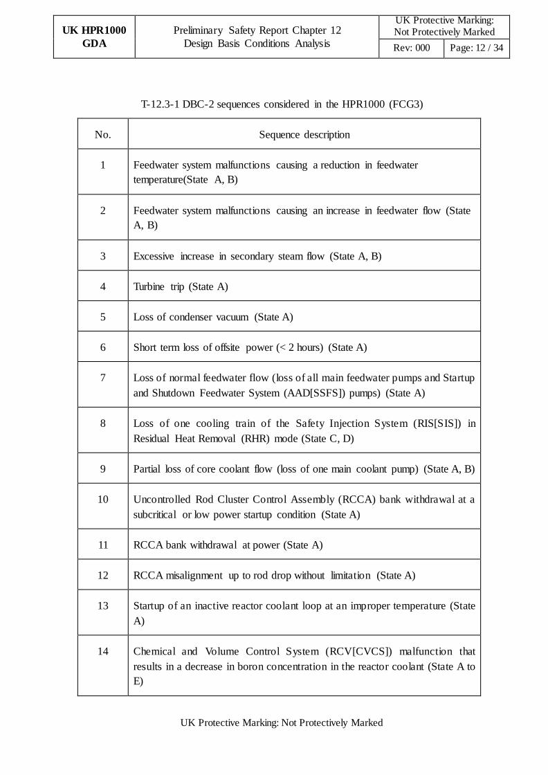
12.3.3.3 DBC-2: Anticipated Operating Occurrences
For HPR1000 (FCG3), the DBC-2 list is provided in T-12.3-1 below, which will be the
basis of the UK HPR1000 DBC-2 fault list to be assessed in the GDA PCSR.
UK HPR1000
GDA
Preliminary Safety Report Chapter 12
Design Basis Conditions Analysis
UK Protective Marking: Not Protectively Marked
Rev: 000 Page: 12 / 34
UK Protective Marking: Not Protectively Marked
T-12.3-1 DBC-2 sequences considered in the HPR1000 (FCG3)
No. Sequence description
1 Feedwater system malfunctions causing a reduction in feedwater
temperature(State A, B)
2 Feedwater system malfunctions causing an increase in feedwater flow (State
A, B)
3 Excessive increase in secondary steam flow (State A, B)
4 Turbine trip (State A)
5 Loss of condenser vacuum (State A)
6 Short term loss of offsite power (< 2 hours) (State A)
7 Loss of normal feedwater flow (loss of all main feedwater pumps and Startup
and Shutdown Feedwater System (AAD[SSFS]) pumps) (State A)
8 Loss of one cooling train of the Safety Injection System (RIS[SIS]) in
Residual Heat Removal (RHR) mode (State C, D)
9 Partial loss of core coolant flow (loss of one main coolant pump) (State A, B)
10 Uncontrolled Rod Cluster Control Assembly (RCCA) bank withdrawal at a
subcritical or low power startup condition (State A)
11 RCCA bank withdrawal at power (State A)
12 RCCA misalignment up to rod drop without limitation (State A)
13 Startup of an inactive reactor coolant loop at an improper temperature (State
A)
14 Chemical and Volume Control System (RCV[CVCS]) malfunction that
results in a decrease in boron concentration in the reactor coolant (State A to
E)
UK HPR1000
GDA
Preliminary Safety Report Chapter 12
Design Basis Conditions Analysis
UK Protective Marking: Not Protectively Marked
Rev: 000 Page: 13 / 34
UK Protective Marking: Not Protectively Marked
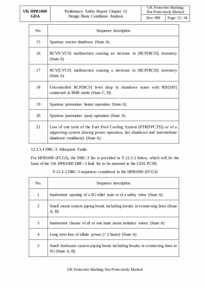
No. Sequence description
15 Spurious reactor shutdown (State A)
16 RCV[CVCS] malfunction causing an increase in (RCP[RCS]) inventory
(State A)
17 RCV[CVCS] malfunction causing a decrease in (RCP[RCS]) inventory
(State A)
18 Uncontrolled RCP[RCS] level drop in shutdown states with RIS[SIS]
connected in RHR mode (State C, D)
19 Spurious pressuriser heater operation (State A)
20 Spurious pressuriser spray operation (State A)
21 Loss of one train of the Fuel Pool Cooling System (PTR[FPCTS]) or of a
supporting system (during power operation, hot shutdown and intermediate
shutdown conditions) (State A)
12.3.3.4 DBC-3: Infrequent Faults
For HPR1000 (FCG3), the DBC-3 list is provided in T-12.3-2 below, which will be the
basis of the UK HPR1000 DBC-3 fault list to be assessed in the GDA PCSR.
T-12.3-2 DBC-3 sequences considered in the HPR1000 (FCG3)
No. Sequence description
1 Inadvertent opening of a SG relief train or of a safety valve (State A)
2 Small steam system piping break including breaks in connecting lines (State
A, B)
3 Inadvertent closure of all or one main steam isolation valves (State A)
4 Long term loss of offsite power (> 2 hours) (State A)
5 Small feedwater system piping break including breaks in connecting lines to
SG (State A, B)

UK HPR1000
GDA
Preliminary Safety Report Chapter 12
Design Basis Conditions Analysis
UK Protective Marking: Not Protectively Marked
Rev: 000 Page: 14 / 34
UK Protective Marking: Not Protectively Marked
No. Sequence description
6 Forced reduction in reactor coolant flow (3 pumps) (State A)
7 Inadvertent loading of a fuel assembly in an improper position (State E)
8 Uncontrolled RCCA bank withdrawal (during shutdown conditions) (State
A)
9 Uncontrolled single RCCA withdrawal (State A)
10 SG tube rupture (one tube) (State A)
11 Inadvertent opening of a pressuriser safety valve (State A)
12 Rupture of a line carrying primary coolant outside containment (e.g. nuclear
sampling line) (State A)
13 Small break Loss of Coolant Accident (LOCA) (at power) including a break
in the Emergency Boration System (RBS[EBS]) injection line (State A)
14 Small break LOCA (at shutdown, RIS[SIS] not connected in RHR mode)
including a break in the RBS[EBS] injection line (State A, B)
15 Gaseous waste tank break (State A to F)
16 Liquid waste effluent tank break (State A to F)
17 Volume control tank break (State A to F)
18 Long term loss of offsite power (>2 hours) affecting fuel pool cooling
(State A)
19 Loss of one train of the PTR[FPCTS] or of a supporting system (with the
reactor core offloaded to the fuel pool) (State F)
20 Isolatable piping failure on a system connected to the spent fuel pool (State A
to F)
12.3.3.5 DBC-4: Limiting Accidents
For HPR1000 (FCG3), the DBC-4 list is provided in T-12.3-3 below, which will be the

UK HPR1000
GDA
Preliminary Safety Report Chapter 12
Design Basis Conditions Analysis
UK Protective Marking: Not Protectively Marked
Rev: 000 Page: 15 / 34
UK Protective Marking: Not Protectively Marked
basis of the UK HPR1000 DBC-4 fault list to be assessed in the GDA PCSR.
T-12.3-3 DBC-4 sequences considered in the HPR1000 (FCG3)
No. Sequence description
1 Large steam system piping break (State A, B)
2 Inadvertent opening of a SG relief or safety valve (State B)
3 Large Feedwater system piping break (State A, B)
4 Long term loss of offsite power (in intermediate shutdown and cold
shutdown conditions) (State C)
5 Reactor coolant pump seizure (locked rotor) or Reactor coolant pump shaft
break (State A)
6 Spectrum of RCCA ejection accidents (State A)
7 Boron dilution due to a non- isolatable rupture of a heat exchanger tube
(during shutdown conditions) (State C, D, E)
8 Steam Generator tube rupture (two tubes in one SG) (State A)
9 Large break LOCA (LB-LOCA) (up to the surge line break, at power) (State
A)
10 Intermediate LOCA (at power and in a shutdown condition) (State A, B)
11 Small break LOCA, including a break in the emergency boration system
injection line (during shutdown conditions, and RIS[SIS] under RHR
operation mode) (State C, D)
12 RHR system piping break inside (outside) containment (≤DN 250) (State C,
D)
13 Inadvertent opening of the dedicated depressurisation device (State A, B)
14 Fuel handling accident (State A to F)
15 Spent fuel transport vessel drop (State A to F)

UK HPR1000
GDA
Preliminary Safety Report Chapter 12
Design Basis Conditions Analysis
UK Protective Marking: Not Protectively Marked
Rev: 000 Page: 16 / 34
UK Protective Marking: Not Protectively Marked
No. Sequence description
16 Failure of radioactivity containing equipment in nuclear auxiliary building
(State A to F)
17 Non isolable small break or isolable RIS[SIS] break (≤250 mm) in RHR
mode affecting fuel pool cooling (during refuelling) (State E)
12.4 Fault Schedule Methodology
For the UK HPR1000, the PIE list will be identified using a combination of deterministic
assessment with engineering judgements via a systematic review of all SSCs that support
the normal operation of the plant. This will include all SSCs that may contain radioactive
material or whose failure or mal-operation may result in a transient on the plant that
could result in the release of radioactive material. The review will be based on the current
good practices in PIE identification e.g. Failure Modes and Effects Analysis (FMEA) or
other appropriate approaches combined with engineering judgements.
For the UK HPR1000, the list of events will be produced based on that of the HPR1000
and will include potential additional events identified by the systematic review of the
design of the UK HPR1000 and the operating experience feedback of the similar units.
For each PIE identified the review will also identify the safeguards required to deliver the
three fundamental safety functions of
a) Control of reactivity;
b) Removal of heat from the reactor and from the fuel store;
c) Confinement of radioactive material, shielding against radiation and control of planned
radioactive releases, as well as limitation of accidental radioactive releases.
A fault schedule for the UK HPR1000 will be addressed in the GDA PCSR. A process for
the fault schedule production will also be outlined in the GDA PCSR. According to
Reference [1], it is likely that the fault schedule will contain the following information:
a) A list of all PIEs with their frequency identified;
b) The safety function, the associated safety system(s) and their safety classification for
each fault;
c) For frequent faults, a second line of protection to satisfy the requirement of diversity
protection;
d) Reference to the fault analysis that demonstrates that the UK HPR1000 plant is
adequately protected for the events listed.

UK HPR1000
GDA
Preliminary Safety Report Chapter 12
Design Basis Conditions Analysis
UK Protective Marking: Not Protectively Marked
Rev: 000 Page: 17 / 34
UK Protective Marking: Not Protectively Marked
12.5 DBC Analysis Methodology and Assumptions
12.5.1 Analysis Rules
The analysis rules provide a conservative analysis methodology to validate the design of
the safety systems provided to ensure the three fundamental safety functions are delivered
following accidents and that sufficient safety systems are provided in the design. These
rules are sufficiently conservative to demonstrate an appropriate design margin remains
following the limiting faults.
This chapter describes the deterministic safety analysis performed for HPR1000 (FCG3)
to illustrate the overall performance of the HPR1000 technology following accidents. The
results of the analysis demonstrate that the current design provisions to protect against
accidents are appropriate.
In parallel with the deterministic analysis, a comprehensive probabilistic safety analysis
is undertaken. The Probabilistic Safety Assessment (PSA) analysis assesses the overall
safety objectives of HPR1000. The PSA assessment is described in chapter 14.
In this sub-chapter, the rules defined for the assessment of HPR1000 (FCG3) are referred
to as ‘DBC fault analysis rules’. The examples of the deterministic analysis presented in
this chapter follow these rules.
Acceptance Criteria
The acceptance criteria for the assessment of the HPR1000 (FCG3) design are based on
the applicable regulation in China. It is recognised that the legislative limits specified in
China may not be sufficient to support the design of the UK HPR1000 with its more
complex structure of consequence targets. Therefore a review of existing relevant UK and
international best practice will be undertaken to produce UK HPR1000 specific
quantitative safety targets for the development of the UK HPR1000 design from the
HPR1000 design with the aim of completing this complex process prior to the start of
detailed design work. These will then be utilised in the assessment of the design for the
UK HPR1000 and provide part of the evidence to support the fundamental safety
objectives reported in the GDA PCSR.
The detailed radiological release assessment of these events assumes data consistent with
the success criteria for each category of event and demonstrates that the limits in the
regulations are met. The safety criteria defined in terms of radiological limits are called
Safety Criteria. For the DBA, the approach followed is to identify surrogate criteria that,
if met, are consistent with the assumptions made in the identification of the safety
systems required for each PIE and the radiological release assessment. These surrogate
criteria, which are also called as Decoupled criteria, are either specified in Chinese
legislation or have been agreed with the National Nuclear Safety Administration of China
(NNSA). Therefore the decoupled criteria to be met in DBA analysis are:
a) No Departure from Nucleate Boiling (DNB) occurs in DBC-1 and DBC-2 events, or

UK HPR1000
GDA
Preliminary Safety Report Chapter 12
Design Basis Conditions Analysis
UK Protective Marking: Not Protectively Marked
Rev: 000 Page: 18 / 34
UK Protective Marking: Not Protectively Marked
for DBC-3/4 events with a breach of the secondary circuit;
b) Less than 10% of the fuel rods experience DNB in DBC-3 events;
c) Less than 10% of the volume fraction of the fuel at the limiting point melts in DBC-3
or DBC-4 events (excluding LOCA);
d) Less than 10% of the fuel rods experience DNB in DBC-4 events (excluding LOCA),
the core geometry is not affected and core cooling continues to remove decay heat;
e) Criteria for LOCA:
1) Peak clad temperature. The calculated maximum fuel element clad temperature
shall not exceed 1204℃;
2) Maximum clad oxidation. The calculated total oxidation of the clad at the limiting
point shall not exceed 17% of the total clad thickness before oxidation;
3) Maximum hydrogen generation. The calculated amount of hydrogen generated
from the chemical reaction of the clad with water or steam shall not exceed 1% of
the amount that would be generated if all of the clad material in the active core
region, were to react;
4) Coolable geometry. Calculated changes in core geometry shall be such that the
core remains capable of being cooled;
5) Long-term cooling. After any calculated successful initial operation of the
Emergency Core Cooling System (ECCS), the calculated core temperature shall
be maintained at an acceptably low value and decay heat shall be removed for the
extended period of time required by the long- lived radioactivity remaining in the
core.
f) For transients without significant clad oxidation, the peak clad temperature shall not
exceed 1482℃;
g) In safe shutdown conditions, the reactor core remains subcritical;
h) The maximum Linear Power Density at hot spot shall not exceed 590 W/cm for
DBC-2.
In addition, specific criteria will be applied for events in cold shutdown conditions and
faults related to the spent fuel pool.
To demonstrate that DNB does not occur, the ratio of the heat flux at which DNB would
be predicted to occur in the current conditions and the current heat flux is calculated,
known as the DNB Ratio (DNBR). A conservative value for this ratio has been
established for the HPR1000 (FCG3) assessment, consistent with the methods used for its
calculation. DNB is assumed to occur if the DNBR is below this limit value.
Codes approved by the NNSA have been used for transient simulation and minimum
UK HPR1000
GDA
Preliminary Safety Report Chapter 12
Design Basis Conditions Analysis
UK Protective Marking: Not Protectively Marked
Rev: 000 Page: 19 / 34
UK Protective Marking: Not Protectively Marked
DNBR calculations. Similar codes to those used at HPR1000 (FCG3) will be used for the
UK HPR1000 analysis. The actual analysis codes to be used for transient simulation and
DNBR calculation for the UK HPR1000 will depend on the fuel vendor chosen for the
UK project. Details of the specific codes and methods used will be provided as part of the
GDA PCSR. Therefore details of the codes and methods used for HPR1000 (FCG3) are
not included in the Preliminary Safety Report (PSR).
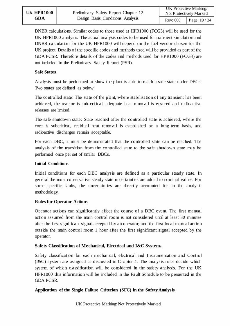
Safe States
Analysis must be performed to show the plant is able to reach a safe state under DBCs.
Two states are defined as below:
The controlled state: The state of the plant, where stabilisation of any transient has been
achieved, the reactor is sub-critical, adequate heat removal is ensured and radioactive
releases are limited.
The safe shutdown state: State reached after the controlled state is achieved, where the
core is subcritical, residual heat removal is established on a long-term basis, and
radioactive discharges remain acceptable.
For each DBC, it must be demonstrated that the controlled state can be reached. The
analysis of the transition from the controlled state to the safe shutdown state may be
performed once per set of similar DBCs.
Initial Conditions
Initial conditions for each DBC analysis are defined as a particular steady state. In
general the most conservative steady state uncertainties are added to nominal values. For
some specific faults, the uncertainties are directly accounted for in the analysis
methodology.
Rules for Operator Actions
Operator actions can significantly affect the course of a DBC event. The first manual
action assumed from the main control room is not considered until at least 30 minutes
after the first significant signal accepted by an operator, and the first local manual action
outside the main control room 1 hour after the first significant signal accepted by the
operator.
Safety Classification of Mechanical, Electrical and I&C Systems
Safety classification for each mechanical, electrical and Instrumentation and Control
(I&C) system are assigned as discussed in Chapter 4. The analysis rules decide which
system of which classification will be considered in the safety analysis. For the UK
HPR1000 this information will be included in the Fault Schedule to be presented in the
GDA PCSR.
Application of the Single Failure Criterion (SFC) in the Safety Analysis

UK HPR1000
GDA
Preliminary Safety Report Chapter 12
Design Basis Conditions Analysis
UK Protective Marking: Not Protectively Marked
Rev: 000 Page: 20 / 34
UK Protective Marking: Not Protectively Marked
The consequences of a single failure are considered in the DBA. In the DBA, a single
failure, independent with the postulated initial event, and which may affect all or part of
the equipment required is considered. The single failure considered in the reference plant
DBA can be an active single failure (in the short term) or a passive single failure
(considered 24 hrs after the initiating fault). It is recognised that these rules may have to
be adapted in the frame of UK HPR1000 GDA.
Loss of Off-Site Power (LOOP)
In the DBC fault analysis, LOOP is assumed to occur during full power operation
conditions for DBC-3 and DBC-4 events if that assumption is conservative.
12.5.2 Main Assumptions
Assumptions related to plant parameters
Parameters covering the plant initial conditions are basic inputs to the fault analysis. Plant
initial conditions decide the initial state of plant when the fault occurs. Relevant
parameters considered in defining the plant initial conditions include:
a) Core power;
b) Pressuriser pressure;
c) RCP[RCS] average temperature;
d) Pressuriser level;
e) SG level;
f) SG water mass.
The initial values of parameters are chosen by adding or subtracting the maximum
uncertainties to the nominal value of each parameter in the most conservative way for
each DBC event.
Assumptions related to core parameters
In assessing the core response, conservative values for reactivity coefficients, power
distributions, fission power and decay heat after reactor trip are assumed.
I&C signals
I&C signals are classified into different safety classifications as discussed in Chapter 8.
Safety Category 1 Function (FC1) and Safety Category 2 Function (FC2) I&C signals are
considered in the deterministic fault analysis. Other I&C signals (which are not FC1 or
FC2) are also considered if the assumption on their operation is conservative.
Conservative assumptions are made on uncertainties associated with the I&C setpoints
and time delays for signals to be generated are modelled in a conservative manner.
Safety systems functions and characteristics
UK HPR1000
GDA
Preliminary Safety Report Chapter 12
Design Basis Conditions Analysis
UK Protective Marking: Not Protectively Marked
Rev: 000 Page: 21 / 34
UK Protective Marking: Not Protectively Marked
In identifying the performance of the modelled safety systems the following is assumed:
a) System performance which leads to the worst results covering all times in component
life;
b) Most onerous single failure which reduces the level of system performance;
c) Only FC1 and FC2 safety systems are considered in the fault analysis. Other safety
systems which are not FC1 or FC2 classified are also considered if the assumption of
their operation is conservative.
12.6 Design Basis Analysis
During the HPR1000 (FCG3) design process, the design basis faults listed in sub-chapter
12.3 have been studied for the DBC analysis. The analysis has followed the rules and
assumption described in sub-chapter 12.5. The results of the HPR1000 (FCG3) DBC
analysis confirm that the acceptance criteria discussed in sub-chapter 12.5 are met.
12.6.1 Examples of Assessment
For the PSR, the results of three representative events are provided below to demonstrate
the overall approach followed in the analysis and to show the robustness of the HPR1000
design. The GDA PCSR will discuss the detailed analysis procedure adopted, identify the
codes used and present results for the UK HPR1000.
The assessments of the three representative events for the HPR1000 (FCG3) plant have
been submitted to the NNSA of China as part of the HPR1000 (FCG3) Preliminary Safety
Analysis Report (PSAR). The analysis results for these events are appropriate to reveal
characteristics of the HPR1000 (FCG3). The examples events are as followings:
a) Uncontrolled RCCA bank Withdrawal at Power (URWP);
b) SLB;
c) LB-LOCA from full-power conditions.
12.6.2 Uncontrolled Rod Cluster Control Assembly Bank Withdrawal at Power
12.6.2.1 Description
An URWP results in the insertion of positive reactivity leading to an increase in the core
heat flux. There is a net increase in the reactor coolant temperature and pressure as the
heat transfer from the primary loops to the steam generators lags behind the core power
generation.
In the event of a slow reactivity insertion transient, there is a small increase in nuclear
power while the temperature in the core rises substantially, which can lead to reactor trip
by reactor protection signal.
In the event of a very fast insertion transient, the nuclear power increases very rapidly in
contrast to the coolant temperature, the transfer of the heat to the coolant being relatively
UK HPR1000
GDA
Preliminary Safety Report Chapter 12
Design Basis Conditions Analysis
UK Protective Marking: Not Protectively Marked
Rev: 000 Page: 22 / 34
UK Protective Marking: Not Protectively Marked
slower. In that case, there would be a high neutron flux reactor trip.
The URWP event has been analysed as part of the HPR1000 (FCG3) PSAR. The results
of a typical sequence are presented below.
12.6.2.2 Typical transient sequence
The following sequence represents the sequence of events most likely to occur during a
URWP transient, including the actions of the safety systems.
The reactivity insertion causes an increase of the nuclear power and consequently the
heat flux and coolant temperature. During this phase, a reactor trip could be initiated by a
number of protection channels, e.g. power range high neutron flux protection. For any of
the rates of withdrawal of the RCCA that can occur protection channels are available to
provide protection for the core and maintain the core subcritical following shutdown.
Turbine trip is actuated following the reactor trip via a check-back signal and the residual
heat is removed through the SGs by the main steam bypass or by the main steam relief
train. The feedwater supply is provided by the Emergency Feedwater System (ASG[EFS])
if Main Feedwater Flow Control System (ARE[MFFCS]) is isolated during the transient.
The RBS[EBS] system is used for boration during the cooldown to take the core to the
long term safe state.
The normal or auxiliary pressuriser spray or the pressuriser safety valves are used to
depressurise the RCP[RCS].
12.6.2.3 Acceptance criteria
For this accident the following acceptance criteria are defined:
The minimum DNBR during the transient must remain above the limit value discussed in
sub-chapter 12.5.1, i.e. no DNB occurs during the transient.
12.6.2.4 Methods and assumptions
The transient simulation and minimum DNBR calculations have been performed using
codes approved by the NNSA of China, as discussed in 12.5.1 above.
To be conservative, different power levels have been considered, bounding neutronic data
have been used, and conservative uncertainty assumption have been applied to the
protection system and mitigation actions.
The single failure is applied to one reactor protection signal channel (depending on which
signal is actuated during the transient).
12.6.2.5 Results and conclusion
The results of the analysis show that for all possible RCCA withdrawal rates the
minimum DNBR during the transient remains above the limit discussed in sub-chapter
12.5.1 and thus DNB does not occur during the transient. Therefore the acceptance

UK HPR1000
GDA
Preliminary Safety Report Chapter 12
Design Basis Conditions Analysis
UK Protective Marking: Not Protectively Marked
Rev: 000 Page: 23 / 34
UK Protective Marking: Not Protectively Marked
criteria for this event are met.
T-12.6-1 gives an example of the sequence of events following an URWP for the
HPR1000 (FCG3). F-12.6-1 to F-12.6-3 present the transient conditions for the main
parameters for the case resulting in the lowest value of minimum DNBR.
T-12.6-1 Time sequence of URWP (the most onerous case)
Event Time(s)
Uncontrolled RCCA banks withdrawal 0.0
Reactor trip 69.0
RCCA banks start to insert 71.0
The minimum DNBR occurs 71.4
F-12.6-1 Thermal power and nuclear power-URWP

UK HPR1000
GDA
Preliminary Safety Report Chapter 12
Design Basis Conditions Analysis
UK Protective Marking: Not Protectively Marked
Rev: 000 Page: 24 / 34
UK Protective Marking: Not Protectively Marked
F-12.6-2 Pressurizer Pressure-URWP
F-12.6-3 Reactor Coolant Average Temperature -URWP
12.6.3 Steam Line Break (SLB)
12.6.3.1 Description
The main SLB break is defined as the rupture of a main steam line. The following
description considers the event initiated from hot shutdown conditions as this minimises
the energy stored in the core and results in the largest potential return to power during the
transient.

UK HPR1000
GDA
Preliminary Safety Report Chapter 12
Design Basis Conditions Analysis
UK Protective Marking: Not Protectively Marked
Rev: 000 Page: 25 / 34
UK Protective Marking: Not Protectively Marked
The steam released from the break depressurises and cools the secondary side of the SG
and leads to a rapid decrease in the temperature and pressure of the RCP[RCS]. The
cooldown of the primary coolant results in an insertion of positive reactivity due to the
positive moderator density coefficient. If the RCCA contributing the most negative
reactivity is assumed stuck in its fully withdrawn position after reactor trip, there is an
increased possibility that the core will become critical during the cooldown and return to
power. In these circumstances it must be shown that DNB does not occur, as discussed in
sub-chapter 12.5.1.
The following discussion of the event and its consequences are based on the analysis
presented in the PSAR for HPR1000 (FCG3).
12.6.3.2 Typical transient sequence
This accident is analysed from hot shutdown initial conditions.
Following the break occurring, the pressure of the SG rapidly decreases. When the fall in
the SG pressure reaches the ‘high SG pressure drop (MAX1)’ setpoint or the ‘low SG
pressure’ setpoint is reached, the Main Steam Isolation Valves (MSIVs) are closed. If the
break is located upstream of the MSIV it cannot be isolated by the MSIV on the affected
SG. The affected SG will continue to blow down through the break to the containment.
The low load ARE[MFFCS] line will be isolated if the affected SG pressure reaches the
‘SG pressure low 2’ setpoint. If the ARE[MFFCS] low load lines are isolated, the
ASG[EFS] will be actuated following a ‘SG level low2 (WR, Wide Range)’ signal.
With the steam flow continuing, the temperature and pressure in the RCS continues to fall
and results in an insertion of positive reactivity. When the ‘pressure of pressuriser low 3’
setpoint is reached, the RIS[SIS] is actuated to protect the reactor.
The controlled state is reached with the affected SG empty of water with the decay heat
being removed by the Main Steam Relief Trains (VDA[MSRT]) of the unaffected SGs.
12.6.3.3 Acceptance criteria
The limiting criterion for this study is demonstrating that DNB does not occur. This is
demonstrated by showing that the minimum DNBR remains above the limit value
specified as the criterion for the HPR1000 (FCG3) analysis condition II events, as
discussed in sub-chapter 12.5.1 above.
12.6.3.4 Methods and assumptions
The transient simulation and minimum DNBR calculations have been performed using
codes approved by the NNSA of China as discussed in sub-chapter 12.5.1 above.
The key assumptions made for the analysis are listed below:
a) A maximum heat transfer coefficient across the SG tubes is used in the study. In
addition, no credit is taken for the heat transferred to the reactor coolant through reverse

UK HPR1000
GDA
Preliminary Safety Report Chapter 12
Design Basis Conditions Analysis
UK Protective Marking: Not Protectively Marked
Rev: 000 Page: 26 / 34
UK Protective Marking: Not Protectively Marked
heat transfer from the two unaffected SGs to maximise the cooldown of the RCP[RCS];
b) Perfect moisture separation in the SG is assumed. This assumption is conservative as a
substantial quantity of water is likely to be entrained in the steam flow, resulting in lower
heat removal from the secondary system via the break and consequently in a less severe
cooldown transient;
c) Minimum safety injection capability is assumed. The single failure of 1 Medium Head
Safety Injection (MHSI) pump is assumed;
d) Core-related assumptions
1) The moderator temperature coefficient corresponding to End of Cycle (EOC) with
all the RCCAs inserted, except for the RCCA having the highest worth stuck in its
fully withdrawn position;
2) The Doppler defect versus power level considers two cases:
- case 1: a Doppler power defect of 1197pcm at 20% Full Power (FP), which covers
all fuel cycles and stuck rod combinations resulting in a Doppler power defect
between 1197pcm and 1724pcm at 20%FP;
- case 2: a Doppler power defect of 1724pcm at 20% FP, which covers all fuel
cycles and stuck rod combinations resulting in a Doppler power defect higher than
1724pcm at 20%FP.
3) The Doppler temperature coefficient of -4.4 pcm/℃;
4) Shutdown margin is 3300pcm;
5) No credit has been taken for core residual heat to slow the RCP[RCS] cooldown;
e) The single failure of 1 Medium Head Safety Injection (MHSI) pump is assumed.
12.6.3.5 Results and conclusion
The analysis of the limiting case in the HPR1000 (FCG3) PSAR has shown that the
calculated minimum DNBR is greater than the criterion limit defined as discussed in
sub-chapter 12.5.1. Therefore DNB does not occur following a SLB at HPR1000 (FCG3).
Therefore no fuel damage will occur following a SLB accident and all the criteria for this
event are satisfied.
T-12.6-2 gives the sequence of events following a SLB accident from hot shutdown
conditions for HPR1000 (FCG3). F-12.6-4 and F-12.6-5 present the transient conditions
for nuclear power, thermal power and steam flow.

UK HPR1000
GDA
Preliminary Safety Report Chapter 12
Design Basis Conditions Analysis
UK Protective Marking: Not Protectively Marked
Rev: 000 Page: 27 / 34
UK Protective Marking: Not Protectively Marked
T-12.6-2 Time sequence of SLB for hot shutdown conditions
event
Time/s
case1 case2
Break occur 0 0
Steam line and ARE[MFFCS] isolation signal 5 5
PZR empty 14 14
SI signal 17.9 17.9
Thermal power peak 230.7 276
F-12.6-4 Thermal power and nuclear power

UK HPR1000
GDA
Preliminary Safety Report Chapter 12
Design Basis Conditions Analysis
UK Protective Marking: Not Protectively Marked
Rev: 000 Page: 28 / 34
UK Protective Marking: Not Protectively Marked
F-12.6-5 Steam flow
12.6.4 LB-LOCA at Full-power Conditions
12.6.4.1 Description
The LB-LOCA is defined as a large break of an RCP[RCS] pipe, or on any pipe
connecting to RCP[RCS] before the first isolation valve forming part of the RCP[RCS]
Boundary (RCPB). The event is analysed from full power conditions as this plant state
has the largest stored energy in both the RCP[RCS] and the fuel.
Following the LB-LOCA RCP[RCS] water is rapidly discharged from the primary circuit
to the containment via the break. This leads to a rapid decrease in RCP[RCS] pressure
and the water level in the Pressuriser. This can result in a reduction of heat removal from
the fuel with a consequent increase in fuel temperature.
The impact of LB-LOCA has been considered in the design of the HPR1000 (FCG3). The
analysis of these events should show that the acceptance criteria discussed in sub-chapter
12.5.1 are satisfied.
12.6.4.2 Typical transient sequence
The condition most likely to happen during a LB-LOCA transient, including actions of
the main safety systems are described below.
The break results in a rapid loss of RCP[RCS] inventory. The loss of fluid results in a
decrease in the RCP[RCS] pressure and Pressuriser level. The rapid decrease of pressure
causes a rapid decrease in moderator density in the core. The consequential decrease of
core reactivity is sufficient to take the core subcritical causing a rapid reduction in core
power. Subsequently, significant voidage of the fluid in the core combined with reac tor
UK HPR1000
GDA
Preliminary Safety Report Chapter 12
Design Basis Conditions Analysis
UK Protective Marking: Not Protectively Marked
Rev: 000 Page: 29 / 34
UK Protective Marking: Not Protectively Marked
trip, borated water injection from the Accumulator (ACC) and the RIS[SIS] pumps
ensures the core remains shutdown.
A reactor trip is initiated following a low pressuriser pressure signal. The reactor trip
signal automatically trips the turbine and closes the main feedwater high load lines. A
‘Low pressuriser pressure signal 3’ generates a safety injection signal, which
automatically actuates the MHSI, Low Head Safety Injection (LHSI) and ASG[EFS]
Systems. Borated water from the MHSI, ACC and LHSI flows into the core to cool the
fuel clad. These stop any further increase in the temperature of fuel clad, place the reactor
in the controlled state, and ensure sufficient heat removal from the fuel, the core remains
subcritical and the water inventory in the core is steady or increasing.
The steam created in the reactor core does not contain a significant amount of boron.
Therefore the concentration of boron in the RCP[RCS] will increase with time. To
prevent blocking of coolant channels within the fuel by boron crystals, operator actions to
maintain the boron concentration below the crystallization limit are necessary. Therefore,
in the later stages of the event, the LHSI injection point must be switched from just the
cold leg to a combination of cold leg and hot leg to control the boron concentration in the
core.
Long term cooling of reactor core is provided by at least one train of RIS[SIS] in Safety
Injection mode with water flows into both the cold and hot legs from the LHSI.
12.6.4.3 Acceptance criteria
The LOCA analyses should meet the following acceptance criteria:
a) The calculated maximum fuel element clad temperature shall not exceed 1204℃;
b) Maximum clad oxidation. The calculated total oxidation of the clad at the limiting
point shall not exceed 17% of the total clad thickness before oxidation;
c) Maximum hydrogen generation. The calculated total amount of hydrogen generated
from the chemical reaction of the clad with water or steam shall not exceed 1% of the
amount that would be generated if all of the clad material in the active core, were to react;
d) Coolable geometry. Calculated changes in core geometry shall be such that the core
remains capable of being cooled;
e) Long-term cooling. After any calculated successful initial operation of the ECCS, the
calculated core temperature shall be maintained at an acceptably low value and decay
heat shall be removed for the extended period of time required by the long- lived
radioactivity remaining in the core.
12.6.4.4 Methods and assumptions in HPR1000 (FCG3)
The analysis of the LB-LOCA for HPR1000 (FCG3) has utilised the deterministic
realistic method. The method introduces penalties into a thermal hydraulic analysis code
to ensure that uncertainties on the parameters considered in the analysis are bounded.

UK HPR1000
GDA
Preliminary Safety Report Chapter 12
Design Basis Conditions Analysis
UK Protective Marking: Not Protectively Marked
Rev: 000 Page: 30 / 34
UK Protective Marking: Not Protectively Marked
Sensitivity studies were performed to ensure that the worst case was identified.
Conservative assumptions were adopted as discussed in subchapter 12.5 and confirmed
via sensitivity analysis. These assumptions can be divided into 4 types:
a) Initial conditions associated with the steady state;
b) Modelling of the accident scenario;
c) Safety system performance;
d) Core parameters.
12.6.4.4.1 Initial conditions associated with the steady state
The Initial conditions for the steady state were selected to be conservative. The main
assumptions are discussed below:
a) The initial core power was that for full-power operation increased by the maximum
measurement error for steady state operation;
b) The temperature of the primary coolant was the nominal temperature for full-power
operation, reduced by the maximum expected temperature fluctuation and measurement
error. This combination was shown to be the most conservative by a sensitivity analysis;
c) The Pressuriser pressure was the nominal value for full power operation increased by
the maximum operational pressure fluctuation and measurement error. This results in the
maximum delay to the generation of the reactor trip signal and safety injection signal;
d) The primary coolant flow assumed was the thermal design flow, the minimum
calculated reactor flow for design purposes;
e) Maximum core bypass flow to minimise the amount of flow through the fuelled region
available for core cooling;
f) 10% of the SG tubes were assumed to be plugged for calculating the initial water
inventory of the primary circuit. The calculation of reverse heat transfer between primary
and secondary circuit assumes no plugging as this maximises the amount of energy
transferred to the primary water from the secondary side of the SGs;
g) Minimum containment pressure and temperature and maximum humidity, as this
delays core reflooding.
12.6.4.4.2 Accident condition
The following key assumptions have been made to define the accident scenario modelled
in the HPR1000 (FCG3) analysis.
a) The break was assumed to be on the cold leg between the pump and the inlet to the
reactor vessel;
b) Maximum delays were assumed in the generation of the safety injection signal and any

UK HPR1000
GDA
Preliminary Safety Report Chapter 12
Design Basis Conditions Analysis
UK Protective Marking: Not Protectively Marked
Rev: 000 Page: 31 / 34
UK Protective Marking: Not Protectively Marked
flow from the RIS[SIS] or the ACC to the broken leg is assumed to be lost;
c) LOOP is assumed to occur at the same time as the break. This has the maximum
impact on the performance of the safety systems.
12.6.4.4.3 Safety system
The performance of the safety systems can have a significant impact on the course of the
transient. To ensure that the results of the transient are appropriately conservative the
performance of the individual safety system has been pessimised as discussed below.
12.6.4.4.3.1 Safety injection
a) A Single failure of the Emergency Diesel Generator (EDG) in the safeguard train
connected to an intact loop has been assumed. This leads to the loss of a train of the
RIS[SIS] (including a MHSI pump and a LHSI pump) and a train of the ASG[EFS];
b) Minimum SI pump performance corresponding to the end of component life with a
maximum resistance in the SI injection pipe;
c) Maximum temperature of the water in the In-containment Refuelling Water Storage
Tank (IRWST).
12.5.4.4.3.2 Accumulator
Sensitivity studies were undertaken to identify conservative assumptions for the flowrate
and water temperature from the accumulator.
12.6.4.4.4 Core parameters
Maximum values for the ratio of power in the peak channel to the average channel (FH),
the power at the hottest point in the core relative to the average core point power, (FQ),
the decay heat and the worst axial power shape were assumed.
12.6.4.5 Results and conclusion in HPR1000 (FCG3)
Sensitivity studies were undertaken using the above assumptions to identify the worst
case. T-12.6-3 gives an example of the sequence of events following a LB-LOCA for
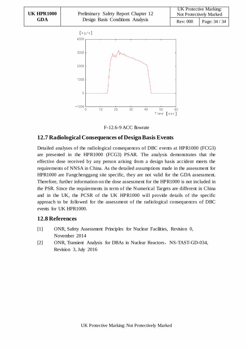
HPR1000 (FCG3). F-12.6-6 to F-12.6-9 present the transient conditions for the main
parameters for the case resulting in the highest value of Peak Clad Temperature (PCT).
For this worst case, the PCT calculated in the HPR1000 (FCG3) analysis was 992.2℃
(see T-12.6-4).
The PCT limit and the remaining acceptance criteria identified in sub-chapter 12.6.4.4
above were shown to be met for HPR1000 (FCG3).

UK HPR1000
GDA
Preliminary Safety Report Chapter 12
Design Basis Conditions Analysis
UK Protective Marking: Not Protectively Marked
Rev: 000 Page: 32 / 34
UK Protective Marking: Not Protectively Marked
T-12.6-3 Time sequence of LB LOCA
Event Time(s)
RT signal 4.65
SI signal 8.00
Event Time(s)
Start of accumulator injection 14.21
Start of SI injection 38.01
Start of core reflooding 38.58
End of accumulator injection 43.51
Start of ASG[EFWS] 63.01
T-12.6- 4 PCT following LB LOCA
PCT
temperature(℃) 992.2
time(s) 7.5
F-12.6-6 Peak clad temperature

UK HPR1000
GDA
Preliminary Safety Report Chapter 12
Design Basis Conditions Analysis
UK Protective Marking: Not Protectively Marked
Rev: 000 Page: 33 / 34
UK Protective Marking: Not Protectively Marked
F-12.6-7 Primary pressure
F-12.6-8 Primary water inventory
UK HPR1000
GDA
Preliminary Safety Report Chapter 12
Design Basis Conditions Analysis
UK Protective Marking: Not Protectively Marked
Rev: 000 Page: 34 / 34
UK Protective Marking: Not Protectively Marked
F-12.6-9 ACC flowrate
12.7 Radiological Consequences of Design Basis Events
Detailed analyses of the radiological consequences of DBC events at HPR1000 (FCG3)
are presented in the HPR1000 (FCG3) PSAR. The analysis demonstrates that the
effective dose received by any person arising from a design basis accident meets the
requirements of NNSA in China. As the detailed assumptions made in the assessment for
HPR1000 are Fangchenggang site specific, they are not valid for the GDA assessment.
Therefore, further information on the dose assessment for the HPR1000 is not included in
the PSR. Since the requirements in term of the Numerical Targets are different in China
and in the UK, the PCSR of the UK HPR1000 will provide details of the specific
approach to be followed for the assessment of the radiological consequences of DBC
events for UK HPR1000.
12.8 References
[1] ONR, Safety Assessment Principles for Nuclear Facilities, Revision 0,
November 2014
[2] ONR, Transient Analysis for DBAs in Nuclear Reactors,NS-TAST-GD-034,
Revision 3, July 2016