ulp temperature-compensated rtc on msp430f6736 · ulp temperature-compensated rtc on msp430f6736 5...
TRANSCRIPT
Application Report SLAA596 – April 2013
1
ULP Temperature-Compensated RTC on MSP430F6736 Percy Yu/Alex Cheng Semi/AEC/MSP430
ABSTRACT
This application report introduces the methodology to implement an ultra-low power real-time clock (RTC) with a temperature-compensation function in the MSP430F6736. This report describes the temperature characteristics of the crystal and use of the RTC_C module of the MSP430F6736 plus software to implement an ultra-low power RTC, with an automatic temperature compensation feature and a second ticks generation function. Finally, this application builds reference code, which runs on the MSP430F6736; this report provides the test results.
_____________________________________________________________________________
Contents 1. Introduction ................................................................................................................................... 2 2. RTC in Smart Meter ....................................................................................................................... 2 2.1. Crystal Frequency Temperature Compensation ......................................................................... 3 2.2. Temperature Measurement .......................................................................................................... 4 2.3. Implementation of RTC_C Module ............................................................................................... 6 2.4. Ultra-Low Power Second Ticks Generation ................................................................................ 8 3. Test Results ................................................................................................................................ 12 4. References .................................................................................................................................. 12
Figures Figure 1. Crystal Temperature Curve .................................................................................................... Figure 2. NTC Temperature Measurement Circuit ................................................................................ Figure 3. RTC_C Block Diagram .......................................................................................................... 6 Figure 4. RTC_C Module Software Control Flow ................................................................................ 7 Figure 5. Frequency Compensation and Second Ticks Generation.................................................. 8 Figure 6. Fill 1-Second Counting With Different Clocks for ULP ....................................................... 9 Figure 7. Ultra-Low Power Second Ticks Generation ...................................................................... 10 Figure 8. ULP Second Ticks Software FLow ..................................................................................... 11
Tables Table 1. RTC Accuracy Test Result ................................................................................................... 12
SLAA596
2 ULP Temperature-Compensated RTC on MSP430F6736
1. Introduction The current smart meter is an electrical energy metering device that tends to integrate an increasing number of functions, including information exchanging, multi-toll control, automatic meter reading, and so forth. Multi-toll control is a key function for energy conservation and is widely used around the world. The purpose of multi-toll control is to charge energy users at different rates in different time segments. Therefore, a smart meter must know the exact time while measuring energy consumption. Thus, an RTC is the basis of the multi-toll control feature. The smart meter must work at an extremely wide temperature range, so the RTC must be self-adapted across the entire working temperature range and ensure consistent accuracy. Another consideration is the power consumption of the RTC. In a region like China, a smart meter must keep awake even if mains power drops, the RTC function must also consume very low power. Texas Instruments’ new E-meter silicon MSP430F673x, running at 25 MHz, is an ultra-low power, highly flexible and powerful mixed signal MCU. It integrated 3 independent 24-bit high-resolution ADCs and an extra 10-bit high-speed ADC, as well as varied digital peripherals. Specifically, MSP430F673x integrated a flash-based hardware RTC calendar. It is ideal for a single-chip smart electricity meter solution. 2. RTC in Smart Meter The RTC is the fundamental function for multi-toll control in the smart meter. The RTC generates two outputs for the other functions of the smart meter: • Calendar: The calendar is the format of year/month/day/hour/minute/second. This format must be
none-volatile during power down and reset because the smart meter may be working in difficult environments, but the electrical energy bill must always be accurate.
• 1-second tick: The 1-second tick is a square pulse signal generated by the RTC chip once per second. The 1-second tick is used for RTC calibration and certification.
Because both calendar and 1-second pulse is related to the multi-toll control, there are very strict requirements on them: 1. Accuracy—The RTC must be very accurate. In most specifications, the error rate under room
temperature should be less than 5 ppm. 2. Temperature compensated—Because the frequency of the crystal may drift away when working,
temperature rises or drops. The RTC function must be able to self-compensate crystal drift so that it can remain accurate across the entire working range. The RTC error rate across the entire working temperature has different specifications in different countries. In China, specifications indicate the limitation is 10 ppm.
3. Ultra-low power—The RTC function must be awake even if the mains power fails. During power failure, the smart meter is powered by embedded unchangeable battery which must be run for at least 5 years. So the power consumption of the RTC is critical. In most countries, power consumption of the RTC must be less than 2 µA.

SLAA596
ULP Temperature-Compensated RTC on MSP430F6736 3
2.1. Crystal Frequency Temperature Compensation All MCU-based smart meter solutions use a 32-kHz low-frequency watch crystal as one of the clock sources. The frequency output of the crystal varies considerably due to temperature drift. It is necessary to compensate the RTC for this temperature drift for higher time-keeping accuracy from standard crystals. Figure 1 shows the typical temperature curve of a 32-kHz crystal.
The curve in Figure 1 is very close to a parabola curve. So the frequency variation of a 32-kHz crystal can be predicted by the following formula:
E = K * (T-T0)*(T-T0) + B Equation 1
Where: • E is the frequency error of the crystal. • T is the crystal working temperature. From the crystal temperature curve (see Figure 1) and the formula we can see the frequency error relates to three factors: K, T0, and B. B is the frequency deviation of a crystal in room temperature. The frequency deviation of each crystal is not the same, but the frequency deviation of the single crystal is its inherent characteristics and does not change with time. The frequency deviation of a crystal can be measured at room temperature—not precisely, but approximately 25°C is close enough because the parabola curve is quite flat in the central point. T0 and K are two factors that describe the parabola curve; they denote the central point of the curve and the roll down speed, respectively. These two factors are determined by the production process of the crystal. Usually they are almost the same among the same batch of crystals.
Figure 1. Crystal Temperature Curve

SLAA596
4 ULP Temperature-Compensated RTC on MSP430F6736
In some circumstances, the entire crystal temperature curve is divided into three or five segments, in temperature axis. On each of the segments, a parabola curve represents the temperature feature of the crystal in this temperature range. The three or five parabola curves illustrate the temperature feature of a crystal. This method helps gain a more accurate picture of the real characteristics of a crystal. Normally, the 32-kHz crystal vendor can provide to their end user the temperature curve of their crystal and the related parameters K and T0. This makes it possible to compensate crystal frequency error with software without much effort on calibration. 2.2. Temperature Measurement After obtaining the crystal temperature factor K, T0 from the crystal vendor, and calibrating the crystal’s deviation on room temperature, we must measure the working temperature for overall frequency error calculation. The MSP430F6736 includes a 10-bit ADC, to which an on-chip temperature sensor is connected internally. Because the MSP430F6736 IC is located very close to the 32-kHz crystal on an e-meter board, the temperature of the crystal can be treated identical to the one measured by an on-chip temperature sensor. So, connecting on-chip, 10-bit ADC (ADC10) and the on-chip temperature sensor is the simplest way to measure the crystal working temperature. To use an internal temperature sensor for temperature measurement, just set ADC10 on channel 10 and ensure the sample period is greater than 30 µs. Accuracy is one important limitation of the internal temperature sensor of the MSP430F6736. Its maximum error is 3°C, which in return results in up to a 13 ppm error on frequency calculation, in 85°C testing point. So the internal temperature sensor of the MSP430F6736 is hard to use in an e-meter application before manual calibration. For better accuracy, external temperature sensor can be used. A typical low-cost temperature sensor is an NTC resistor. The resistance of an NTC resistor changes dramatically when its working temperature changes. So if we can measure the resistance of NTC, we can get its working temperature. Figure 2 shows the circuit to measure NTC resistance.
SLAA596
ULP Temperature-Compensated RTC on MSP430F6736 5
A. Simplest structure B. VCC drift considered structure
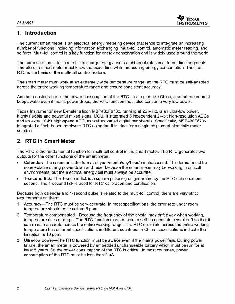
The simplest use of NTC is shown at the left side of Figure 2 (part A). V-RTC is the power source for the resistor ladder. It is supplied by MSP430F6736 GPIO and can be shut down to GND to save power when temperature is not measured. TEMP is the tap where the voltage on NTC is fed to ADC10. So the resistor of NTC is:
TEMPRTCV
TEMPNTC VV
RVR−×
=−
VV-RTC is the power supply voltage for the MCU. R is the resistance for R. So if we can measure the voltage drop on NTC (VTEMP) with ADC10, we can calculate the resistance of NTC. In a real e-meter application, the power supply for MCU VV-RTC may drift because of working temperature or disturbance from the power grid. So the calculated resistance of NTC may have error. It is preferable to use the second structure to measure, as shown at the right side of Figure 2 (part B). In this structure a new branch resistor ladder is implemented. So the calculation on NTC resistance is:
2211
2
)( RVRRVRRVR
TEMPTEMP
TEMPNTC ×−+×
××=
The NTC resistance calculation of structure B is irrelevant to power supply
Figure 2. NTC Temperature Measurement Circuit

SLAA596
6 ULP Temperature-Compensated RTC on MSP430F6736
2.3. Implementation of RTC_C Module The RTC_C module in MSP430F673x is dedicate for the RTC function in a smart meter. The RTC_C contains the following features: • RTC and calendar mode providing seconds, minutes, hours, day of week, day of month, month, and
year (including leap year correction) • Protection for RTC registers • Interrupt capability • Selectable BCD or binary format • Programmable alarms • RTC calibration for crystal offset error • RTC compensation for crystal temperature drifts • Operation in LPM3.5 • Operation from a separate voltage supply with programmable charger for that separate voltage supply
Figure 3. RTC_C Block Diagram

SLAA596
ULP Temperature-Compensated RTC on MSP430F6736 7
The RTC_C lets the end user compensate crystal error, resulting from either crystal individual frequency offset or temperature influence. As for crystal frequency offset, the end user must calibrate crystal in room temperature and determine the error between crystal frequency and standard 32768 Hz. As for temperature influence, the end user can calculate crystal frequency error based on the temperature curve of the crystal with measured temperature. All errors are in PPM and must be written into RTCOCAL and RTCTCMP, respectively, to compensate offset and temperature influence. The RTC_C has dedicated clock source from external 32-kHz crystal and have a dedicated power supply. Thus RTC_C can work in stand-alone mode without taking any MCU MIPS, and the power consumption is only 0.3 µA, typically in room temperature. The RTC_C also integrated calendar and alarm functions. Figure 4 shows the RTC_C module implementation flow chart.
Foreground TA0 ISR
RTC_C init
AD10 ISRSet Pin V-RTC to 1
RTCTCRDY flag set?
RTC_C start
Unlock RTC_C
Set RTCOCAL
lock RTC_C
Setup TA0
Start ADC10
Start TA0
Get Vtemp1
Get Vtemp
Calculate temperature
Set Pin V-RTC to 0
Calculate Frequency error in PPM
Set RTCCMP
Clear ADC10IFG0
Figure 4. RTC_C Module Software Control Flow

SLAA596
8 ULP Temperature-Compensated RTC on MSP430F6736
The RTC_C can also output second ticks (1-Hz clock) on the RTCCLK pin. But because the frequency compensation in the RTC_C is in 60-µs step, the second ticks output from the RTC_C can only be accurate in 1-minute scale. This means the accumulated error of 60 consecutive second ticks can be calibrated to 0, but the error of a single second tick will be up to 60 ppm. 2.4. Ultra-Low Power Second Ticks Generation In many applications, the error on second ticks must be measured individually or in 10-second increments. Here we use software to fine-tune the accuracy of each second tick. The MSP430F6736 has an extremely flexible clock system, and the integrated FLL plus a lot of prescale dividers easily facilitate a 1-MHz SMCLK clock internally. Because SMCLK is sourced from external 32-kHz crystal through PLL, the error rate of external crystal is the same as that of SMCLK. So the frequency compensation to SMCLK can also be made with the same rate as to the crystal. Figure 5 shows how to use 1-MHz SMCLK clock and Timer_A to compensate frequency error and generate second ticks.
Crystal OffsetCrystal
Temperature Coefficient
+
1MHz SMCLK
TACCR
TAR
Basic count per second
Timer_ASecond ticks
Figure 5. Frequency Compensation and Second Ticks Generation
The same actions are performed in the frequency compensation stage as are done when using RTC_C: 1. Get working temperature through external NTC. 2. Calculate the overall frequency error E caused by temperature and initial deviation based on the
temperature parabola curve of the crystal (see Equation 1) in PPM. 3. Subtract the frequency error E and get the exact SMCLK clock count per second. Then the second ticks generation is actually a frequency divider, through use of Timer_A. Because the clock source of Timer_A is 1-MHz SMCLK, adding or subtracting one SMCLK in TACCR is equal to fine-tuning the output second ticks frequency by 1 ppm. Power consumption is the limitation of the preceding temperature-compensated second ticks generation system. If the 1-MHz SMCLK keeps running for Timer_A, MSP430 must run in LPM0 while

SLAA596
ULP Temperature-Compensated RTC on MSP430F6736 9
sleeping, and the power consumption is typically 83 µA. However, in many applications, like e-meter, the entire system is powered by battery if the main power source drops. Power consumption of the RTC must drop to microampere level. Because higher speed clock consumes more power during the same time, one way to reduce power consumption is to compose different clocks, high-speed clock and low-speed clock, to filling the entire 1-second counting period.
1M CLK
...32K CLK
1 Second
...
32668/32768 second
Switch to High Frequency clock Generate 1s pulse
Figure 6. Fill 1-Second Counting With Different Clocks for ULP
As Figure 6 shows, if a 32-kHz clock is used to count for 32668/32768 of a second, and the 1-MHz clock is used to count the last 100/32768 of a second, and the point of when to generate the seconds tick is determined, it is still possible to fine-turn the accuracy of the second ticks in 1-ppm steps, while reducing the overall power consumption dramatically to:
32768100
3276832668
03 LPMLPME III +=
Where: • IE is the average power consumption. • ILPM0 is the power consumption in LPM0 mode. • ILPM3 is the power consumption in LPM3 mode. In the MSP430F6736 data sheet, LPM0 mode power consumption is 83 µA and LPM3 mode power consumption is 2.5 µA. So the average power consumption for software RTC and second ticks generation is 2.74 µA In this application note, two Timer_A modules are used to implement clock switching and second ticks generation. Figure 7 shows the time sequence of two TA modules, TA0 and TA2.
SLAA596
10 ULP Temperature-Compensated RTC on MSP430F6736
TA0
0FFFFh
TA0CCR0TA0CCR1
TA2
0FFFFhTA2CCR0TA2CCR1
capture Tick 1s pulse and switch off FLL
Switch on FLL and TA2
Frequency Compensation
Sourced from 32KHz ACLK
Sourced from 1MHz SMCLK
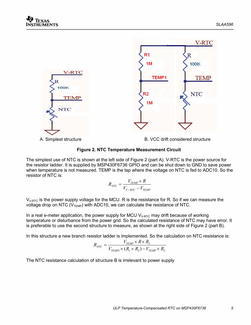
Figure 7. Ultra-Low Power Second Ticks Generation
TA2 sources from the 1-MHz SMCLK, and is shut down until TA0 ISR wakes it up. TA0 sources from the 32-kHz ACLK, and runs in up and compare out mode. TA0 is always on. When TA2 is switched on to fine-turn the second ticks, TACCR0 stores the value. Because TA2 sources from SMCLK, it is necessary to switch on FLL several cycles of ACLK before switching on TA2, to allow enough time to stabilize SMCLK before using TA2 for SMCLK counting. TACCR1 stores the value when FLL is switched on.
SLAA596
ULP Temperature-Compensated RTC on MSP430F6736 11
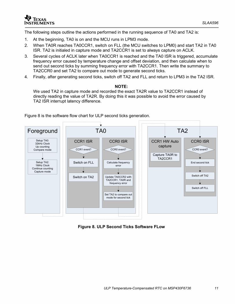
The following steps outline the actions performed in the running sequence of TA0 and TA2 is:
1. At the beginning, TA0 is on and the MCU runs in LPM3 mode. 2. When TA0R reaches TA0CCR1, switch on FLL (the MCU switches to LPM0) and start TA2 in TA0
ISR. TA2 is initialed in capture mode and TA2CCR1 is set to always capture on ACLK. 3. Several cycles of ACLK later when TA0CCR1 is reached and the TA0 ISR is triggered, accumulate
frequency error caused by temperature change and offset deviation, and then calculate when to send out second ticks by summing frequency error with TA2CCR1. Then write the summary to TA2CCR0 and set TA2 to compare out mode to generate second ticks.
4. Finally, after generating second ticks, switch off TA2 and FLL and return to LPM3 in the TA2 ISR.
NOTE: We used TA2 in capture mode and recorded the exact TA2R value to TA2CCR1 instead of directly reading the value of TA2R. By doing this it was possible to avoid the error caused by TA2 ISR interrupt latency difference.
Figure 8 is the software flow chart for ULP second ticks generation.
TA0
CCR1 ISR CCR0 ISR
ForegroundSetup TA0:
32kHz ClockUp counting
Compare mode
Switch on FLLSetup TA2: 1MHz Clock
Continue countingCapture mode
CCR1 event? CCR0 event?
Calculate frequency error
Set TA2 to compare out mode for second tick
Update TA0CCR2 with TA2CCR1, TA0R and
frequency error
TA2
CCR1 HW Auto capture
CCR0 ISR
Capture TA0R to TA2CCR1
CCR0 event?
End second tick
Switch off TA2Switch on TA2
Switch off FLL
Figure 8. ULP Second Ticks Software FLow

SLAA596
12 ULP Temperature-Compensated RTC on MSP430F6736
3. Test Results This application built an RTC library and ran tests on the MSP430F6736 CSG reference meter. Table 1 shows the RTC accuracy test results. At all test points, the error rate is lower than 10 ppm.
Table 1. RTC Accuracy Test Result
Meas. Temp. (°C)
72.5 62.5 53.5 42.5 33.5 23.5 13.75 3.2 -6.75 -16.75 -27.19 -37.19
RTC error (ppm)
-6.75 -3.4 -1.05 -0.1 0.35 0 -1.15 -1.1 -1.35 -1.9 -1.75 0.1
4. References
[1] TI. MSP430x5xx and MSP430x6xx Family User's Guide (Rev. K) [2] TI. MSP430F673x, MSP430F672x Mixed Signal Microcontroller (Rev. B)

IMPORTANT NOTICE
Texas Instruments Incorporated and its subsidiaries (TI) reserve the right to make corrections, enhancements, improvements and otherchanges to its semiconductor products and services per JESD46, latest issue, and to discontinue any product or service per JESD48, latestissue. Buyers should obtain the latest relevant information before placing orders and should verify that such information is current andcomplete. All semiconductor products (also referred to herein as “components”) are sold subject to TI’s terms and conditions of salesupplied at the time of order acknowledgment.
TI warrants performance of its components to the specifications applicable at the time of sale, in accordance with the warranty in TI’s termsand conditions of sale of semiconductor products. Testing and other quality control techniques are used to the extent TI deems necessaryto support this warranty. Except where mandated by applicable law, testing of all parameters of each component is not necessarilyperformed.
TI assumes no liability for applications assistance or the design of Buyers’ products. Buyers are responsible for their products andapplications using TI components. To minimize the risks associated with Buyers’ products and applications, Buyers should provideadequate design and operating safeguards.
TI does not warrant or represent that any license, either express or implied, is granted under any patent right, copyright, mask work right, orother intellectual property right relating to any combination, machine, or process in which TI components or services are used. Informationpublished by TI regarding third-party products or services does not constitute a license to use such products or services or a warranty orendorsement thereof. Use of such information may require a license from a third party under the patents or other intellectual property of thethird party, or a license from TI under the patents or other intellectual property of TI.
Reproduction of significant portions of TI information in TI data books or data sheets is permissible only if reproduction is without alterationand is accompanied by all associated warranties, conditions, limitations, and notices. TI is not responsible or liable for such altereddocumentation. Information of third parties may be subject to additional restrictions.
Resale of TI components or services with statements different from or beyond the parameters stated by TI for that component or servicevoids all express and any implied warranties for the associated TI component or service and is an unfair and deceptive business practice.TI is not responsible or liable for any such statements.
Buyer acknowledges and agrees that it is solely responsible for compliance with all legal, regulatory and safety-related requirementsconcerning its products, and any use of TI components in its applications, notwithstanding any applications-related information or supportthat may be provided by TI. Buyer represents and agrees that it has all the necessary expertise to create and implement safeguards whichanticipate dangerous consequences of failures, monitor failures and their consequences, lessen the likelihood of failures that might causeharm and take appropriate remedial actions. Buyer will fully indemnify TI and its representatives against any damages arising out of the useof any TI components in safety-critical applications.
In some cases, TI components may be promoted specifically to facilitate safety-related applications. With such components, TI’s goal is tohelp enable customers to design and create their own end-product solutions that meet applicable functional safety standards andrequirements. Nonetheless, such components are subject to these terms.
No TI components are authorized for use in FDA Class III (or similar life-critical medical equipment) unless authorized officers of the partieshave executed a special agreement specifically governing such use.
Only those TI components which TI has specifically designated as military grade or “enhanced plastic” are designed and intended for use inmilitary/aerospace applications or environments. Buyer acknowledges and agrees that any military or aerospace use of TI componentswhich have not been so designated is solely at the Buyer's risk, and that Buyer is solely responsible for compliance with all legal andregulatory requirements in connection with such use.
TI has specifically designated certain components as meeting ISO/TS16949 requirements, mainly for automotive use. In any case of use ofnon-designated products, TI will not be responsible for any failure to meet ISO/TS16949.
Products Applications
Audio www.ti.com/audio Automotive and Transportation www.ti.com/automotive
Amplifiers amplifier.ti.com Communications and Telecom www.ti.com/communications
Data Converters dataconverter.ti.com Computers and Peripherals www.ti.com/computers
DLP® Products www.dlp.com Consumer Electronics www.ti.com/consumer-apps
DSP dsp.ti.com Energy and Lighting www.ti.com/energy
Clocks and Timers www.ti.com/clocks Industrial www.ti.com/industrial
Interface interface.ti.com Medical www.ti.com/medical
Logic logic.ti.com Security www.ti.com/security
Power Mgmt power.ti.com Space, Avionics and Defense www.ti.com/space-avionics-defense
Microcontrollers microcontroller.ti.com Video and Imaging www.ti.com/video
RFID www.ti-rfid.com
OMAP Applications Processors www.ti.com/omap TI E2E Community e2e.ti.com
Wireless Connectivity www.ti.com/wirelessconnectivity
Mailing Address: Texas Instruments, Post Office Box 655303, Dallas, Texas 75265Copyright © 2013, Texas Instruments Incorporated