ultra-dehydration of a reactive epichlorohydrin-containing
TRANSCRIPT

© 2021 The Author(s). Published by the Royal Society of Chemistry Mater. Adv., 2021, 2, 2419–2430 | 2419
Cite this: Mater. Adv., 2021,
2, 2419
Ultra-dehydration of a reactiveepichlorohydrin-containing organic mixtureusing a defect-free thin carbon molecular sievecomposite membrane†
Seong-Joong Kim, ‡a YongSung Kwon,‡ab DaeHun Kim,a Hosik Park, a
Young Hoon Cho, a Seung-Eun Nam*a and You-In Park*a
A high-performance thin carbon molecular sieve (CMS) composite membrane was prepared using a
drop-coating process for dehydration of a ternary mixture (water/IPA/ECH) by a pervaporation process.
The amount of polymer solution dripped onto an alumina disc was varied during the drop-coating
process to optimize the formation of the desired active-carbon layer. A defect-free CMS membrane was
obtained with a dripped amount of 110 mL, resulting in high gas permeance and optimized selectivity.
Furthermore, the CMS membrane was carbonized at 650–800 1C, leading to higher selectivity at
elevated temperature with the decrease of gas permeance due to the shrinkage of its graphene-like
carbon structure. For separation of the water/IPA/ECH ternary mixture, the highest separation
performance (total flux 1.05 kg m�2 h�1) and separation factor (158 692) were obtained from the CMS
membrane carbonized at 700 1C. On the other hand, the CMS membrane showed a unique separation
property: the water flux increased with increasing water content in the feed, without remarkable
reduction of the separation factor (still 4150 000). This is attributed to the rigid pore structure of the
CMS membrane, which provides a molecular sieving separation mechanism. Furthermore, increasing the
feed-solution temperature led to an increase of both the total flux and separation factor. The CMS
membrane performance exhibited the highest separation factor (when compared with other
membranes) for dehydration of the water/IPA binary mixture via pervaporation. Moreover, it was much
higher than that of a polymeric membrane for dehydration of the water/IPA/ECH ternary mixture.
1. Introduction
Epoxy resins are a group of reactive compounds with epoxyrings and have the characteristics of excellent mechanicalstrength, high adhesion, high heat and electrical resistance,and durability.1 Therefore, these resins have been commerciallyavailable for use in adhesives, paints and coatings, electronicmaterials, and composite materials.2 Furthermore, in 2019, theepoxy-resin world market was valued at more than $5.9 billionand this is expected to increase to $10.3 billion by 2027 (CAGRof 7.0%).3
Epoxy resins are generally synthesized by polymerization ofepichlorohydrin (ECH) and phenol, with isopropyl alcohol (IPA)as a solvent.2 To control the molecular weight of the epoxyresin, an excess of ECH is included in the raw material.After the reaction, water remains as a by-product, along withthe epoxy resin (product), a chlorinated impurity, and theunreacted initial raw materials (IPA and ECH).4 For the reuseof ECH from the unreacted and residual mixture, the chlorinatedimpurity can be removed via a simple distillation process.However, the IPA/ECH mixture forms an azeotrope with waterduring the distillation process, which hinders purification of themixture into a high-purity product.5,6 Accordingly, the water/IPA/ECH mixture remaining after the distillation process hastypically just been reused. This causes a gradual reduction inthe reaction efficiency and eventually demands disposal becausethe composition becomes inadequate for reuse.7 Therefore, ifwater (high heat capacity) is preferentially removed through amembrane process, and the IPA/ECH components are separatedand purified through a distillation process, the energy efficiencyof the epoxy-resin manufacturing process can be improved by
a Green Carbon Research Center, Korea Research Institute of Chemical Technology
(KRICT), Gajeong-ro 141, Daejeon 34114, Korea. E-mail: [email protected],
[email protected]; Fax: +82-42-860-7283; Tel: +82-42-860-7241, +82-42-860-7243b Department of Chemical and Biomolecular Engineering, Korea Advanced Institute
of Science and Technology (KAIST), Daejeon, 34141, South Korea
† Electronic supplementary information (ESI) available. See DOI: 10.1039/d0ma00899k‡ These authors contributed equally.
Received 19th November 2020,Accepted 23rd February 2021
DOI: 10.1039/d0ma00899k
rsc.li/materials-advances
MaterialsAdvances
PAPER
Ope
n A
cces
s A
rtic
le. P
ublis
hed
on 1
6 M
arch
202
1. D
ownl
oade
d on
1/1
5/20
22 9
:22:
46 A
M.
Thi
s ar
ticle
is li
cens
ed u
nder
a C
reat
ive
Com
mon
s A
ttrib
utio
n 3.
0 U
npor
ted
Lic
ence
.
View Article OnlineView Journal | View Issue

2420 | Mater. Adv., 2021, 2, 2419–2430 © 2021 The Author(s). Published by the Royal Society of Chemistry
reusing unreacted materials. In addition, it is possible toimplement an environment-friendly epoxy-resin productionprocess by preventing the emission of ECH, which is anenvironmentally harmful material.8
Pervaporation is a unique separation process in which thefeed mixture is supplied as a liquid; then, the liquid feed isconverted to the vapor phase during the separation processthrough decompression of the membrane permeate side. Thisprocess is commonly used for dehydration and removal ofsubstances from an organic aqueous solution and forseparation of organic–organic liquid mixtures.9–12 In particular,many studies have been done to overcome the limitations ofdistillation processes such as the separation of components inan azeotropic mixture (water–alcohol).10,13 Furthermore, thepervaporation process has the advantages of low operatingcost, as well as being environment-friendly and safe.14,15
Indeed, it is a relatively lower-energy consumption process thandistillation because it operates under mild heatingconditions.16,17 Most of the energy used for pervaporation isrequired to maintain the vacuum state on the permeate side ofthe membrane.
The separation mechanism of a pervaporation membranefollows a solution–diffusion model based on the chemicalpotential gradient between the membrane material andpenetrants.12 In particular, hydrophilic polymers such as polyvinylalcohol (PVA),18,19 chitosan,20 Nafion,21 and polyacrylonitrile(PAN)22 have been widely used for dehydration involving anorganic aqueous solution. However, these polymeric membranescome with difficulties related to relatively low chemical andthermal stability, swelling at high temperature, and water in thefeed, as well as a performance trade-off between permeation fluxand selectivity.23–26 Recently, for the dehydration of water/IPA/ECH mixtures, Chaudhari et al. studied the stability andseparation efficiency of PVA/PVAm (polyvinyl amine) blendedmembranes.7 This membrane was stable for up to 15 days inthe reactive ECH-containing mixture solution, but it was relativelyless stable than a crosslinked PVA membrane. Furthermore, theymodified the surface of PVA/TEOS (tetraethyl orthosilicate)membranes with PVAm/STA (silicotungstic acid). With these, aninitial water content drop to 96.23% was observed in thepermeate. The membrane was then operated for 168 h withoutmajor deviation.27
Alternatively, microporous ceramic membranes includingsilica, zeolites, and carbon molecular sieves (CMS) have beeninvestigated as promising candidates for dehydration oforganic mixtures due to their superior chemical and thermalstability. Nevertheless, there are drawbacks: silica has a limitedchemical and hydrothermal stability;23,28 with zeolites it isdifficult to synthesize a defect-free membrane and it alsoexhibits acid sensitivity.28,29 In addition, most inorganicmembranes have problems related to their high material costand to the complexity of their synthesis or manufacturing.28
The CMS membrane is attractive for the pervaporationprocess due to its excellent separation properties and chemicaland thermal stability with a simple manufacturing process,30
but it has seldom been used for pervaporation processes.
The CMS membrane with an ultra-micro pore structure (3–6 Å)can offer high water permeation flux and a high separationfactor through its molecular sieving separation mechanism.Moreover, a CMS membrane possesses an anti-swelling propertyin water-containing mixtures even at elevated temperatures.31
Indeed, the excellent pervaporation performance and stability ofCMS membranes were observed for water/alcohol mixtures(ethanol, methanol, and IPA),28,32–36 water/acetic acid,32 andbenzene/cyclohexane.37 Furthermore, the brittleness of theinitial CMS membranes was overcome by depositing a carbonlayer on a porous substrate such as alumina and stainless steel.35
However, depositing a polymer solution on a substrate is quitecomplex, costly, and a time-consuming process due to theneed for the coating process, which, in some case, needs anintermediate layer and repetitive coating process. The intermediatelayer has frequently been employed to deposit a thin, uniformactive layer without defects by decreasing the pore size andnarrowing the pore-size distribution of the support surface.28
However, a negative influence of the support and intermediatelayer on the membrane performance has been often reportedin terms of its diffusion resistance.38,39 Hence, to achieve themaximized performance of a CMS membrane supported by aporous substrate, the number of intermediate layers should beminimized, and the manufacturing process simplified as well.
In this study, to investigate defect-free high-performanceCMS composite membranes, a simple one-step drop-coatingprocess was employed on an alumina disc without anadditional intermediate layer. These CMS membranes wereused for the dehydration of ECH-containing aqueous mixtures.To the best of our knowledge, the dehydration of anECH-containing aqueous mixture using a pervaporation processwith a CMS membrane has been never reported. Moreover,CMS-membranes have rarely been prepared using a drop-coating method.
Commercial Matrimid polyimide was employed as a precursor,and has the properties of high glass-transition temperature, highcarbon content, and thereby, attractive permeance and selectivity.The CMS membranes were deposited on alumina discs by varyingthe amount of polymer solution dripped during drop-coating, andthen carbonized in the temperature range of 650–800 1C to tailorthe separation performance. Finally, the CMS membranes wereevaluated for the separation of a water/IPA/ECH mixture as well asfor the separation of gases such as He, H2, CO2, N2, and C3H8.Furthermore, the temperature and concentration of the feedmixtures were varied during the pervaporation tests.
2. Experimental2.1 Materials
Alumina powder (CR15) and Matrimid 5218 were purchasedfrom Baikowski and Huntsman Chemical Company, respectively.They were dried at 60 1C for more than 1 week before use. All thesolvents of n-methyl-2-pyrrolidone (NMP, Z99.5%), isopropylalcohol (IPA, 99.9%), and epichlorohydrin (ECH, 499.0%) weresupplied by Samchun Chemicals. For the gas permeation test,
Paper Materials Advances
Ope
n A
cces
s A
rtic
le. P
ublis
hed
on 1
6 M
arch
202
1. D
ownl
oade
d on
1/1
5/20
22 9
:22:
46 A
M.
Thi
s ar
ticle
is li
cens
ed u
nder
a C
reat
ive
Com
mon
s A
ttrib
utio
n 3.
0 U
npor
ted
Lic
ence
.View Article Online

© 2021 The Author(s). Published by the Royal Society of Chemistry Mater. Adv., 2021, 2, 2419–2430 | 2421
He (99.999%), H2 (99.99%), CO2 (99.999%), N2 (99.999%), andC3H8 (99.99%) were used.
2.2 Preparation of a supported CMS membrane on analumina disc
An alumina disc was fabricated by the powder-pressing methodto use as a substrate. A portion of alumina powder (1.5 g) wasused to fill a die of 22 mm diameter, and then compacted usingupper and lower punches at 100 bar. For calcination of anejected alumina disc, the sample was put in a muffle furnace,and the temperature was increased to 600 1C at a heating rate of2 1C min�1 and a soaking time of 1 h. Then the temperaturewas raised to 1180 1C at a ramping rate of 1 1C min�1. Afterremaining for 1 h at 1180 1C, the furnace was cooled by naturalconvection, and an alumina disc with a diameter of 21 mm, athickness of 2.22 mm, and a porosity of 13.3 � 0.76% wasfinally obtained. The alumina disc was polished using sandpaper (1500 grit) and kept in an oven at 60 1C for at least 6 hprior to the polymer coating.
The drop-coating procedure with polymer solution is illustratedin Fig. 1. A polymer solution was prepared by dissolving 5 wt%Matrimid in NMP at 60 1C, and then stirred vigorously for 24 h.Various amounts of Matrimid solution (in the range of 80–130 mL)were dripped onto the alumina disc kept in the oven at 60 1C.Then, the Matrimid solution was spread uniformly using tweezers.The alumina disc with a uniform layer of polymer solution wasdried in the oven at 60 1C for 6 h. The polymer-coated alumina discwas annealed again at 150 1C under vacuum for more than 24 h toremove any residual solvent.
For the carbonization of the polymer-coated alumina disc,the sample was placed on an alumina ceramic plate, andpyrolyzed in a tubular furnace under ultra-high purity heliumgas (99.9999%) with a flow rate of 50 cc min�1 after purging thetube inside at a flow rate of 1000 cc min�1 for 30 min. Thecarbonization temperature (650–800 1C) was reached by heatingat a rate of 2.8 1C min�1, given 1 h of soaking time, and thencooled to o50 1C by natural convection.
2.3 Characterization
The functionalities of the CMS membranes after pyrolysis werecharacterized using attenuated total reflectance Fouriertransform infrared spectroscopy (ATR-FTIR, Bruker ALPHA-PFTIR spectrometer). An X-ray photoelectron spectrometer (XPS,AXIS NOVA, KRATOS Analytical) was utilized to investigate thechemical change of the CMS membranes. The XPS analysis wascarried out using a monochromatic Al-Ka X-ray source (15 keV)
at a pass energy of 160 and 40 eV for survey analysis andhigh-resolution analysis, respectively. The pressure in themeasurement chamber was maintained at o1.0 � 10�8 torr.The structural change of the CMS membranes was studied usingX-ray diffraction (XRD) patterns from a Rigaku D/Max-2200Vdiffractometer attached to a Cu tube and a graphite mono-chromator at 40 kV. Raman spectra were recorded with aSENTERRA spectrometer (Bruker) using an excitation sourcewith 532 nm wavelength. To monitor the surface and cross-section of the CMS membrane and the carbon layer deposited onthe alumina disc, a scanning electron microscope (SEM, SECSNE-4500M) and an energy dispersive X-ray spectroscope (EDS,XFlash6160, Bruker) equipped with a SEM (MAGNA FEG, Tescan)were employed. The thermal decomposition behavior of theMatrimid polyimide was characterized using thermo-gravimetric analysis (TGA, TGA Q5000, TA Instruments, Inc.) ata heating rate of 10 1C min�1 under nitrogen gas. The surfaceproperties of CMS membranes were measured using contactangle (CA, DSA30S, KRUSS GmbH). Deionized water was drippedonto the surface of the CMS membrane, and this was repeatedfive times to ensure reliability.
2.4 Gas permeation test
To identify the CMS membrane with optimized performanceduring drop-coating and to assess the effective pore size of theCMS membranes carbonized at various temperatures, pure-gaspermeation tests were performed using an aluminum modulewith dead-end flow. High purity gases (i.e., He, H2, CO2, N2, andC3H8) were fed into the side of the carbon layer. The gas wasthoroughly purged prior to measurement to replace completelythe previous gas with the one being measured. The operatingpressure was adjusted using a gas regulator and monitoredusing a pressure gage. The volumetric flow rate on the permeateside was measured using a bubble flow meter. All gas permeationtests were implemented at 2 bar and 25 1C. The gas permeancewas indicated in gas permeation units (GPU) as in the followingequation:40
1 GPU = 10�6 cm3 [STP]/(cm2 s cmHg)
The ideal selectivity was calculated from the ratio of individualpure-gas permeances.
2.5 Pervaporation test
The feed solutions, which included pure water and water/IPAand water/IPA/ECH mixtures, were prepared by mixing eachcomponent by weight ratio. The water content in the feed
Fig. 1 Deposition of a defect-free thin CMS composite membrane on the alumina substrate via the drop-coating method.
Materials Advances Paper
Ope
n A
cces
s A
rtic
le. P
ublis
hed
on 1
6 M
arch
202
1. D
ownl
oade
d on
1/1
5/20
22 9
:22:
46 A
M.
Thi
s ar
ticle
is li
cens
ed u
nder
a C
reat
ive
Com
mon
s A
ttrib
utio
n 3.
0 U
npor
ted
Lic
ence
.View Article Online
2422 | Mater. Adv., 2021, 2, 2419–2430 © 2021 The Author(s). Published by the Royal Society of Chemistry
solutions was kept in the range of 5–20 wt%. For the water/IPA/ECH mixture, the weight ratio of ECH to IPA was always fixed at5 to 3. A portion of each feed solution (2 L) was kept in a SUSdouble jacket at specific temperatures (30–60 1C) to maintainthe feed solution at a consistent temperature. The pervaporationtest was carried out in a customized cross-flow system. Themixture solution was fed onto the carbon layer at a flow rate of0.5 L min�1 using a Teflon-coated gear pump. No extra pressurewas applied on the feed side. The opposite (permeate) side of theCMS membrane was kept under vacuum (1.5 torr). The penetrantswere condensed in a cold trap using liquid nitrogen and thenweighed. The weight fraction in the solution was measured usingan FID detector-equipped gas chromatograph (GC, DS 6200,Donam Co.). The detection limit of the GC was 5 ppm for eachgradient. The pervaporation experiment was repeated three times,and the membrane performance was determined by averaging thedata. The permeation flux (J) and separation factor (a) werecalculated as shown in the following equations:41
J ¼ W
A� t
where W is the permeated weight, A is the effective membranesurface area, and t is the permeation time.
a ¼ pwater=pIPAþECHfwater=fIPAþECH
where p is the weight fraction of the permeate side and f is theweight fraction of the feed.
3. Results and discussion
Drop-coating is a simple process used to form a uniform layeron a porous support and is cost-effective due to its ease ofoperation.42 B. Zhang et al. utilized drop-coating for the depositionof a polymer layer with polyetherimide and resorcinol-formaldehyde resin for a carbon membrane.43 However, thederived carbon layer was non-uniform, rough, and thick(450 mm), leading to undesirable gas-separation performance.Furthermore, to achieve acceptable separation performance,the drop and drying processes were repeatedly carried out(several times).44
In this study, drop-coating with polyimide solution provided adefect-free, uniform carbon layer in a single step. The polyimide
was suitable for forming a desirable coating layer even withsub-micro thickness due to its high thermal stability, whichminimizes the deformation (e.g., cracks, delamination, andabsorption into the substrate) of the coating layer duringpyrolysis without any further post-treatment process (e.g., oxidationand crosslinking). The coating process was carried out in anoven at 60 1C because low temperature (o40 1C) causedconstant absorption of polymer solution into the surface poresof the alumina substrate over a long retention time. Highertemperature (480 1C) induced fast evaporation of the solution,resulting in an absorbed and defective coating layer. The drop-coating process applied in this study has shown highreproducibility of the coating thickness (see S2, ESI†).
3.1 Optimization of the drop-coating process
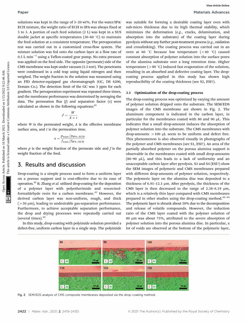
The drop-coating process was optimized by varying the amountof polymer solution dripped onto the substrate. The SEM/EDSimages of the CMS membrane are shown in Fig. 2. Thealuminum component is indicated in the carbon layer, inparticular for the membranes coated with 80 and 90 mL. Thisindicates that a small drop-amount induces the absorption ofpolymer solution into the substrate. The CMS membranes withdrop-amounts 4100 mL seem to be uniform and defect free.This phenomenon is also observed visually in photographs ofthe polymer and CMS membranes (see S1, ESI†). An area of thepartially absorbed polymer on the porous alumina support isobservable in the membranes coated with small drop-amounts(80–90 mL), and this leads to a lack of uniformity and anunacceptable carbon layer after pyrolysis. S3 and S4 (ESI†) showthe SEM images of polymeric and CMS membranes preparedwith different drop-amounts of polymer solution, respectively.The polymeric layer on the alumina disc was deposited to athickness of 6.91–12.1 mm. After pyrolysis, the thickness of theCMS layer is then decreased to the range of 2.38–6.19 mm,which is a relatively thin layer compared with CMS membranesprepared in other studies using the drop-coating method.42–44
The polymeric layer is shrunk about 50% due to the decompositionand release of volatile compounds. However, the reductionratio of the CMS layer coated with the polymer solution of80 mm was about 75%, attributed to the severe absorption ofpolymer solution into the porous alumina disc. In particular, alot of voids are observed at the bottom of the polymeric layer,
Fig. 2 SEM/EDS analysis of CMS composite membranes deposited via the drop-coating method.
Paper Materials Advances
Ope
n A
cces
s A
rtic
le. P
ublis
hed
on 1
6 M
arch
202
1. D
ownl
oade
d on
1/1
5/20
22 9
:22:
46 A
M.
Thi
s ar
ticle
is li
cens
ed u
nder
a C
reat
ive
Com
mon
s A
ttrib
utio
n 3.
0 U
npor
ted
Lic
ence
.View Article Online
© 2021 The Author(s). Published by the Royal Society of Chemistry Mater. Adv., 2021, 2, 2419–2430 | 2423
which may give rise to severe reduction during the carbonizationprocess.
To optimize the drop-amount of the polymer solution and toverify the integrity of the CMS membranes, gas permeationtests were performed with He, H2, CO2, and N2 gases, theresults of which are listed in Table 1. The gas permeance ofall the CMS membranes are as follows: H2 (2.89 Å) 4 CO2
(3.30 Å) 4 He (2.60 Å) 4 N2 (3.64 Å), which corresponds to thekinetic diameter of the gas molecules, except for helium due toits inert property.45 The CMS membranes consist of micropores(5–10 Å) and ultra-micropores (o5 Å), which serve in selectivesurface flow and molecular sieving separation, respectively.46
Thus, condensable CO2 can strongly interact with the CMSmembrane, resulting in higher permeance than for helium.
The gas permeance for all gases decreased with increasingdrop-amount of polymer solution, but the selectivity increased.This is attributed to the thicker and defect-free carbon layerof the CMS membranes coated with the larger drop-amounts ofpolymer solution, as mentioned above. A noticeable increase ofselectivity was observed up to the drop-amount of 110 mL whilethe gas permeance of the CMS membranes steadily decreased.
It is believed that defect-free CMS membranes prepared usingthe drop-coating process can be achieved if the drop-amount is110 mL. For the polymer composite membrane, the optimalamount of polymer solution was somewhat different comparedto the CMS composite membrane (see S5, ESI†). The optimizedselectivity could be obtained with the drop amount of polymersolution more than 90 mL while the gas permeance of all themembranes constantly decreased. This different optimalamount between the polymer and CMS layers is attributed tothe thicker polymer layer (see S3 and S4, ESI†). The thicker layercan provide a more reliable and defect-less pore structure.However, the absorbed and deposited polymer layer onto theporous alumina disc is constantly decomposed and shrunkduring pyrolysis, which may cause a defective mesopore ormicropore (B1 nm). Therefore, to extend the measurement ofgas permeation and pervaporation, a CMS membrane coatedwith a drop-amount of 110 mL was adopted.
3.2 Membrane characterization
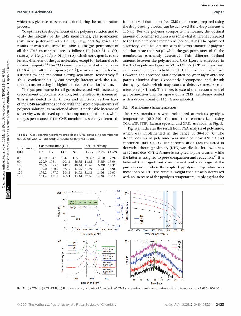
The CMS membranes were carbonized at various pyrolysistemperatures (650–800 1C), and then characterized usingTGA, ATR-FTIR, Raman spectra, and XRD, as shown in Fig. 3.
Fig. 3(a) indicates the result from TGA analysis of polyimide,which was implemented in the range of 30–800 1C. Thedecomposition of polyimide was initiated near 420 1C andcontinued until 800 1C. The decomposition area indicated inderivative thermogravimetry (DTG) was divided into two areasat 520 and 600 1C. The former is assigned to pore creation whilethe latter is assigned to pore compaction and reduction.47 It isbelieved that significant development and shrinkage of thepores occurred when the applied pyrolysis temperature wasmore than 600 1C. The residual weight then steadily decreasedwith an increase of the pyrolysis temperature, implying that the
Table 1 Gas separation performance of the CMS composite membranesdeposited with various drop-amounts of polymer solution
Drop amount(mL)
Gas permeance (GPU) Ideal selectivity
He H2 CO2 N2 H2/N2 He/N2 CO2/N2
80 488.9 1847 1347 185.3 9.967 2.638 7.26990 329.9 1051 901.3 56.35 18.65 5.854 15.99100 256.6 895.0 747.6 40.74 21.96 6.298 18.35110 199.0 550.2 327.5 17.25 31.89 11.53 18.98120 176.2 477.7 294.3 14.73 32.43 11.96 19.97130 161.4 431.8 265.4 13.14 32.86 12.28 20.19
Fig. 3 (a) TGA, (b) ATR-FTIR, (c) Raman spectra, and (d) XRD analysis of CMS composite membranes carbonized at a temperature of 650–800 1C.
Materials Advances Paper
Ope
n A
cces
s A
rtic
le. P
ublis
hed
on 1
6 M
arch
202
1. D
ownl
oade
d on
1/1
5/20
22 9
:22:
46 A
M.
Thi
s ar
ticle
is li
cens
ed u
nder
a C
reat
ive
Com
mon
s A
ttrib
utio
n 3.
0 U
npor
ted
Lic
ence
.View Article Online
2424 | Mater. Adv., 2021, 2, 2419–2430 © 2021 The Author(s). Published by the Royal Society of Chemistry
CMS pore structure became more compact as the pyrolysistemperature increased.
The chemical structure of the CMS membrane is indicatedin Fig. 3(b). The overall peaks in all the CMS membranes areindistinguishable because during pyrolysis, the polymerprecursor undergoes decomposition of its volatile compoundsand rearrangement of its pore structure. Nevertheless, threebroad, weak peaks were observed at 1750, 1556, and 1020 cm�1
(corresponding to CQO, CQC or CQN, and C–N,respectively).34,48 With increasing pyrolysis temperature, theintensity of the peaks was clearly weaker, and then aftermembrane carbonization at 800 1C, no CMS membrane peakswere detected. After the evolution of polyimide during pyrolysis,the CMS membrane was mainly composed of C–C (sp3) andCQC (sp2) bonds with minor chains such as CQO, CQN, andCRN, as shown in S6 (ESI†). The higher carbonizationtemperature caused the transformation of more C–C (sp3) intoCQC (sp2) bonds. Moreover, reduction of the peak intensity inthe N1s spectra of the CMS membranes carbonized at highertemperature was observed in S7 (ESI†), indicating moredecomposition of the nitrogen-containing compounds.
Raman spectroscopy was carried out to investigate thestructure of CMS membranes prepared at different pyrolysistemperatures, as indicated in Fig. 3(c). We confirmed two peakscorresponding to the disordered D-band (B1300 cm�1) andgraphitic G-band (1600 cm�1), which represent amorphouscarbon and ideal graphene sheets, respectively.32 The CMSmembrane is a turbostratic structure in which two structurescoexist. With an increase in the pyrolysis temperature, the ID/IG
ratio (intensity of D-/G-bands) increases, which indicates amore amorphous structure. Moreover, we can calculate theaverage in-plane crystallite size (La) and fractional value (F)for the amount of disordered carbon using the followingequations:49
La ðnmÞ ¼ 4:35� ID
IG
� ��1
Fð%Þ ¼ ID
ID þ IG
Increasing the pyrolysis temperature offers smaller crystallitesize and a higher fractional value of disordered carbon due tothe more severe decomposition of volatile compounds at highertemperature. This causes constant rearrangement of the carbonstructure, resulting in the presence of a more disorderedcarbon structure.
On the other hand, the constant evolution during pyrolysiscan lead to greater compaction and shrinkage of the carbonstructure,50 and this was reflected in the XRD patterns inFig. 3(d). The amorphous peaks in the range of 22–231 appearedand shifted slightly to higher two-theta values at higherpyrolysis temperatures, indicating reduction of the d-spacing.This is attributed to the constant decomposition of polymerchains and rearrangement of graphitic carbon layers, leading toa smaller in-plane size and more severe densification of thecarbon layer with increasing pyrolysis temperature.
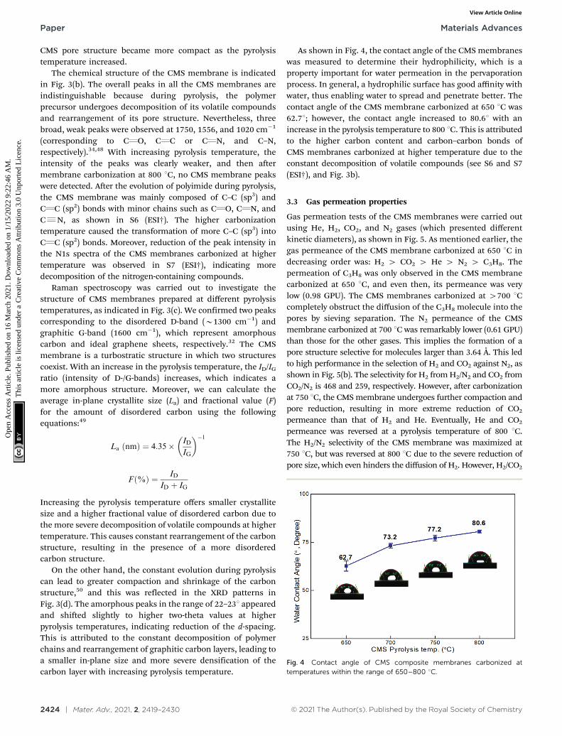
As shown in Fig. 4, the contact angle of the CMS membraneswas measured to determine their hydrophilicity, which is aproperty important for water permeation in the pervaporationprocess. In general, a hydrophilic surface has good affinity withwater, thus enabling water to spread and penetrate better. Thecontact angle of the CMS membrane carbonized at 650 1C was62.71; however, the contact angle increased to 80.61 with anincrease in the pyrolysis temperature to 800 1C. This is attributedto the higher carbon content and carbon–carbon bonds ofCMS membranes carbonized at higher temperature due to theconstant decomposition of volatile compounds (see S6 and S7(ESI†), and Fig. 3b).
3.3 Gas permeation properties
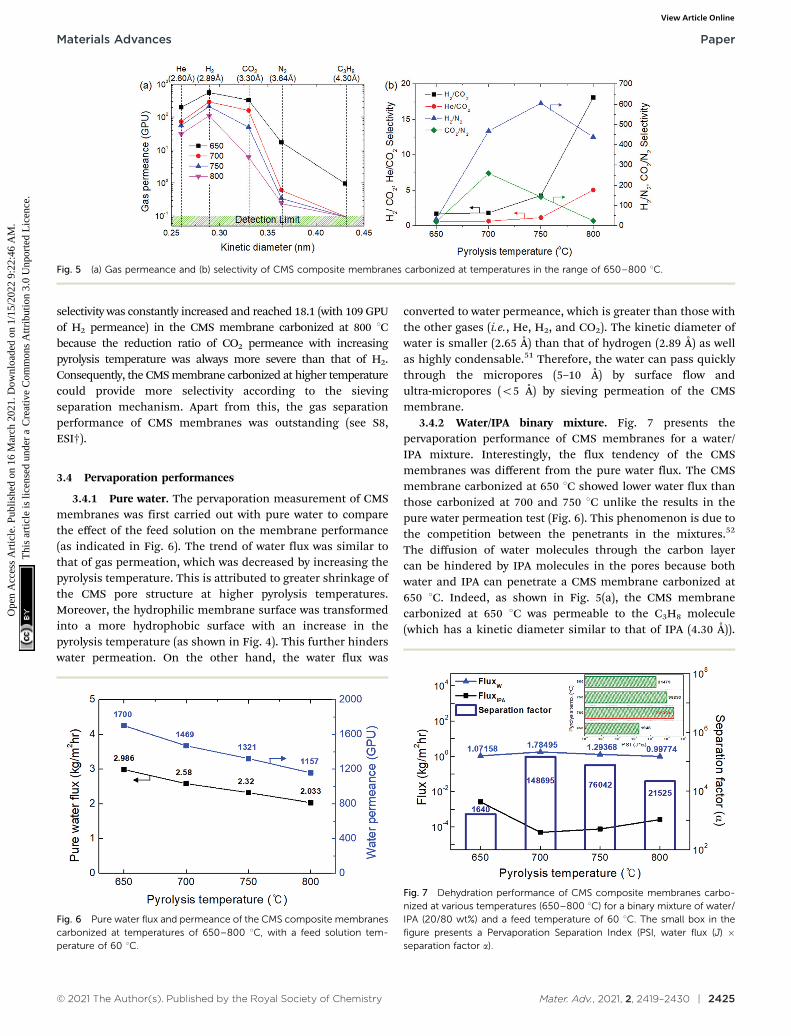
Gas permeation tests of the CMS membranes were carried outusing He, H2, CO2, and N2 gases (which presented differentkinetic diameters), as shown in Fig. 5. As mentioned earlier, thegas permeance of the CMS membrane carbonized at 650 1C indecreasing order was: H2 4 CO2 4 He 4 N2 4 C3H8. Thepermeation of C3H8 was only observed in the CMS membranecarbonized at 650 1C, and even then, its permeance was verylow (0.98 GPU). The CMS membranes carbonized at 4700 1Ccompletely obstruct the diffusion of the C3H8 molecule into thepores by sieving separation. The N2 permeance of the CMSmembrane carbonized at 700 1C was remarkably lower (0.61 GPU)than those for the other gases. This implies the formation of apore structure selective for molecules larger than 3.64 Å. This ledto high performance in the selection of H2 and CO2 against N2, asshown in Fig. 5(b). The selectivity for H2 from H2/N2 and CO2 fromCO2/N2 is 468 and 259, respectively. However, after carbonizationat 750 1C, the CMS membrane undergoes further compaction andpore reduction, resulting in more extreme reduction of CO2
permeance than that of H2 and He. Eventually, He and CO2
permeance was reversed at a pyrolysis temperature of 800 1C.The H2/N2 selectivity of the CMS membrane was maximized at750 1C, but was reversed at 800 1C due to the severe reduction ofpore size, which even hinders the diffusion of H2. However, H2/CO2
Fig. 4 Contact angle of CMS composite membranes carbonized attemperatures within the range of 650–800 1C.
Paper Materials Advances
Ope
n A
cces
s A
rtic
le. P
ublis
hed
on 1
6 M
arch
202
1. D
ownl
oade
d on
1/1
5/20
22 9
:22:
46 A
M.
Thi
s ar
ticle
is li
cens
ed u
nder
a C
reat
ive
Com
mon
s A
ttrib
utio
n 3.
0 U
npor
ted
Lic
ence
.View Article Online
© 2021 The Author(s). Published by the Royal Society of Chemistry Mater. Adv., 2021, 2, 2419–2430 | 2425
selectivity was constantly increased and reached 18.1 (with 109 GPUof H2 permeance) in the CMS membrane carbonized at 800 1Cbecause the reduction ratio of CO2 permeance with increasingpyrolysis temperature was always more severe than that of H2.Consequently, the CMS membrane carbonized at higher temperaturecould provide more selectivity according to the sievingseparation mechanism. Apart from this, the gas separationperformance of CMS membranes was outstanding (see S8,ESI†).
3.4 Pervaporation performances
3.4.1 Pure water. The pervaporation measurement of CMSmembranes was first carried out with pure water to comparethe effect of the feed solution on the membrane performance(as indicated in Fig. 6). The trend of water flux was similar tothat of gas permeation, which was decreased by increasing thepyrolysis temperature. This is attributed to greater shrinkage ofthe CMS pore structure at higher pyrolysis temperatures.Moreover, the hydrophilic membrane surface was transformedinto a more hydrophobic surface with an increase in thepyrolysis temperature (as shown in Fig. 4). This further hinderswater permeation. On the other hand, the water flux was
converted to water permeance, which is greater than those withthe other gases (i.e., He, H2, and CO2). The kinetic diameter ofwater is smaller (2.65 Å) than that of hydrogen (2.89 Å) as wellas highly condensable.51 Therefore, the water can pass quicklythrough the micropores (5–10 Å) by surface flow andultra-micropores (o5 Å) by sieving permeation of the CMSmembrane.
3.4.2 Water/IPA binary mixture. Fig. 7 presents thepervaporation performance of CMS membranes for a water/IPA mixture. Interestingly, the flux tendency of the CMSmembranes was different from the pure water flux. The CMSmembrane carbonized at 650 1C showed lower water flux thanthose carbonized at 700 and 750 1C unlike the results in thepure water permeation test (Fig. 6). This phenomenon is due tothe competition between the penetrants in the mixtures.52
The diffusion of water molecules through the carbon layercan be hindered by IPA molecules in the pores because bothwater and IPA can penetrate a CMS membrane carbonized at650 1C. Indeed, as shown in Fig. 5(a), the CMS membranecarbonized at 650 1C was permeable to the C3H8 molecule(which has a kinetic diameter similar to that of IPA (4.30 Å)).
Fig. 5 (a) Gas permeance and (b) selectivity of CMS composite membranes carbonized at temperatures in the range of 650–800 1C.
Fig. 6 Pure water flux and permeance of the CMS composite membranescarbonized at temperatures of 650–800 1C, with a feed solution tem-perature of 60 1C.
Fig. 7 Dehydration performance of CMS composite membranes carbo-nized at various temperatures (650–800 1C) for a binary mixture of water/IPA (20/80 wt%) and a feed temperature of 60 1C. The small box in thefigure presents a Pervaporation Separation Index (PSI, water flux (J) �separation factor a).
Materials Advances Paper
Ope
n A
cces
s A
rtic
le. P
ublis
hed
on 1
6 M
arch
202
1. D
ownl
oade
d on
1/1
5/20
22 9
:22:
46 A
M.
Thi
s ar
ticle
is li
cens
ed u
nder
a C
reat
ive
Com
mon
s A
ttrib
utio
n 3.
0 U
npor
ted
Lic
ence
.View Article Online
2426 | Mater. Adv., 2021, 2, 2419–2430 © 2021 The Author(s). Published by the Royal Society of Chemistry
Nevertheless, C3H8 permeance was low (0.98 GPU), due torejection of molecules with the kinetic diameter 44.30 Å.Herein, for pervaporation of the water/IPA mixture, theseparation factor of the CMS membrane was 1640. This ispretty high and corresponds to that of a polymer-basedmembrane.53 Therefore, the CMS membrane carbonized at650 1C provided an acceptable separation factor for the water/IPA mixture even though it had the worst pervaporationperformance among the CMS membranes studied in this study.
The highest water flux and separation factor were observedwith the CMS membrane carbonized at 700 1C. This is attributedto the blockage of the CMS membrane to penetration by IPAbecause the membrane pore size was smaller than that of an IPAmolecule. Indeed, the permeance of N2 (kinetic diameter of3.64 Å) was extremely low (0.62–0.25 GPU). Therefore, thecompetition between water and IPA molecules penetrating thepores is negligible, leading to water-dominant permeationwithout hindrance by IPA, resulting in both higher water fluxand a higher separation factor. However, the competitionbetween water and IPA can still occur at the membrane surface,resulting in lower water flux in the feed mixture than for purewater flux.
On the other hand, the water flux steadily decreased withincreasing pyrolysis temperature. This can be attributed to thesevere compaction of the carbon structure, as mentioned inFig. 3(c and d). Moreover, a CMS membrane prepared at higherpyrolysis temperature was more hydrophobic, which weakens
the interaction between water and the membrane surface.Therefore, the retention of water on the membrane surface isless, leading to the reduction of both water flux and theseparation factor. To compare the pervaporation performanceof the CMS membranes with the gas permeance, the water andIPA flux was transformed to the permeance unit (GPU) asshown in S12 (ESI†). The water permeance of 568–1016 GPUwas always higher than for gases such as He, H2, and CO2 whilethe IPA permeance of 0.027–0.31 GPU was remarkably lowerthan even nitrogen (0.25–17.25 GPU). This reflects that thesieving separation is predominant during the pervaporationprocess with CMS membranes.
The pervaporation performance of the CMS membraneswhen varying the feed composition is indicated in S13 (ESI†).As the water ratio in the feed was increased, the water fluxincreased while the separation factor decreased. This is attributedto the more water-dominant sorption to the membrane surfacewith higher water content. Furthermore, it has been oftenreported that water permeation can be hindered by IPA morethan vice versa.32 Nevertheless, it should be noted that the IPAflux of each CMS membrane (regardless of the carbonizationtemperature) was similar across all the feed compositions dueto the size-exclusion property of the CMS membrane.
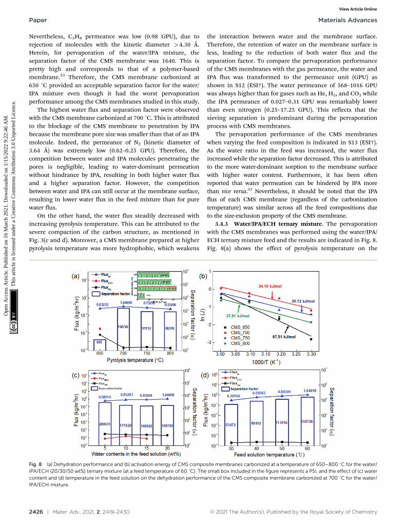
3.4.3 Water/IPA/ECH ternary mixture. The pervaporationwith the CMS membranes was performed using the water/IPA/ECH ternary mixture feed and the results are indicated in Fig. 8.Fig. 8(a) shows the effect of pyrolysis temperature on the
Fig. 8 (a) Dehydration performance and (b) activation energy of CMS composite membranes carbonized at a temperature of 650–800 1C for the water/IPA/ECH (20/30/50 wt%) ternary mixture (at a feed temperature of 60 1C). The small box included in the figure represents a PSI, and the effect of (c) watercontent and (d) temperature in the feed solution on the dehydration performance of the CMS composite membrane carbonized at 700 1C for the water/IPA/ECH mixture.
Paper Materials Advances
Ope
n A
cces
s A
rtic
le. P
ublis
hed
on 1
6 M
arch
202
1. D
ownl
oade
d on
1/1
5/20
22 9
:22:
46 A
M.
Thi
s ar
ticle
is li
cens
ed u
nder
a C
reat
ive
Com
mon
s A
ttrib
utio
n 3.
0 U
npor
ted
Lic
ence
.View Article Online
© 2021 The Author(s). Published by the Royal Society of Chemistry Mater. Adv., 2021, 2, 2419–2430 | 2427
pervaporation performance of the CMS membranes. The waterflux through all the CMS membranes was decreased with theternary mixture feed, compared with those with pure water andwater/IPA mixture feeds. This indicates that the addition ofECH to the water/IPA mixture interferes with water permeationin the membrane pores and with adsorption of water moleculesto the membrane surface due to more competitive conditions.Compared with the feed of pure water, the mixture feed seemsto interact stronger among the penetrants and to promote moreinteractions between the penetrants and membrane due tohydrogen bonding, as well as dipole–dipole and ion–dipoleinteractions.54 For the CMS membrane carbonized at 650 1C,the ECH flux was higher than that of IPA, even though themolecule size of ECH is larger than that of IPA. This isattributed to the stronger polar property of ECH, which allowsstronger interactions with the hydrophilic membrane.7
However, ECH flux was not detected in the CMS membranecarbonized at temperatures higher than 700 1C. It is believedthat the penetration of ECH (which has the largest moleculesize) is restricted by the ultra-micropores of the CMSmembrane (a dominant pore size of o3.64 Å, as shown inFig. 5a). Thus, the IPA flux of B0.00001 kg m�2 h�1 is alsonegligible, but IPA seems to penetrate the CMS membranebetter than ECH following the sieving separation. Then, similarto the results with the water/IPA mixture feed, both the waterflux and separation factor decreased with an increase in thepyrolysis temperature due to compaction of the pore structureand transformation of the membrane surface property fromhydrophilic to more hydrophobic. However, it should be notedthat the CMS membranes provided excellent separation factors(158 726, 91 112, and 86 576) at pyrolysis temperatures of 700,750, and 800 1C. These are performances that exceeded the highpurity of 99.99% for water (see S15, ESI†).
The activation energy (E) for permeation of the CMSmembranes carbonized at temperatures in the range of650–800 1C was calculated using the Arrhenius equation and isillustrated in Fig. 8(b).55
K ¼ K0 � exp � E
RT
� �
where K represents the permeation, K0 is a pre-exponentialfactor, R is the molar gas constant, and T is the absolutetemperature. The activation energy of the CMS membranecarbonized at 700 1C was the lowest because this was a water-selective pore structure that offered a relatively hydrophilicmembrane surface. The activation energy of the CMS membranesincreased with increasing pyrolysis temperature due to thetransformation of the membrane surface from hydrophilic tohydrophobic. The CMS membrane carbonized at 650 1C showedthe highest activation energy because it allowed the penetration ofboth IPA and ECH, albeit only a little.
As shown in Fig. 8(c), the influence of the water content inthe feed on the pervaporation performance was examined usingthe CMS membrane carbonized at 700 1C, which showed themost ideal membrane performance. The water flux increasedand the separation factor decreased with an increase of the
water content in the feed mixture, as mentioned above(S9, ESI†). The separation factor of more than 150 000 at awater content of 20 wt% was still high, even though its trendrelative to the increase of water content was slightly decreased.The diffusion of IPA and ECH, which have relatively largermolecular size, is hindered due to the rigid pores of the CMSmembrane. Therefore, the flux of IPA and ECH slightlydecreased with an increase in the water content of the feedmixture, while the water flux steadily increased. This property isadvantageous for the pervaporation process. The free volumeidentified as the diffusive path in polymeric membranes caneasily be expanded by swelling at high operating temperatureand high water content in the feed solution. This combinationgives rise to a significant increase of the total flux and adecrease of the separation factor.56 Similar results for dehydrationof a water/alcohol mixture using various polymeric membraneshave frequently been reported.9,57,58
Fig. 8(d) shows the performance of the CMS membrane witha feed-solution temperature of 30–60 1C. The water flux andseparation factor of the CMS membranes simultaneouslyincreased with an increase in the feed-solution temperature.The relatively low water flux and separation factor at lowertemperatures can be attributed to the low vapor-pressure drivingforce on the feed side. This is a unique property of the CMSmembrane associated with the sieving separation mechanism.In contrast, the polymeric membrane typically has a trade-offbetween the total flux and separation factor because the freevolume of the polymer is expanded by higher segmental polymerchain motion at elevated temperature, leading to the effect ofincreased swelling, as mentioned above.53,59
On the other hand, it should be noted that for the CMSmembrane, no stability issue (e.g., swelling, dissolution, cracking,or delamination) was caused by highly reactive ECH during thepervaporation test with the water/IPA/ECH mixture. For theseparation of ECH-containing mixtures using a polymericmembrane, the stability of the membrane is one of the mainproblems to be solved.7,27 Moreover, polymeric membranesundergo swelling, which can cause reduction of the separationfactor. In contrast, such problems did not occur with the CMSmembrane due to its high chemical and thermal stability andrigid pores.
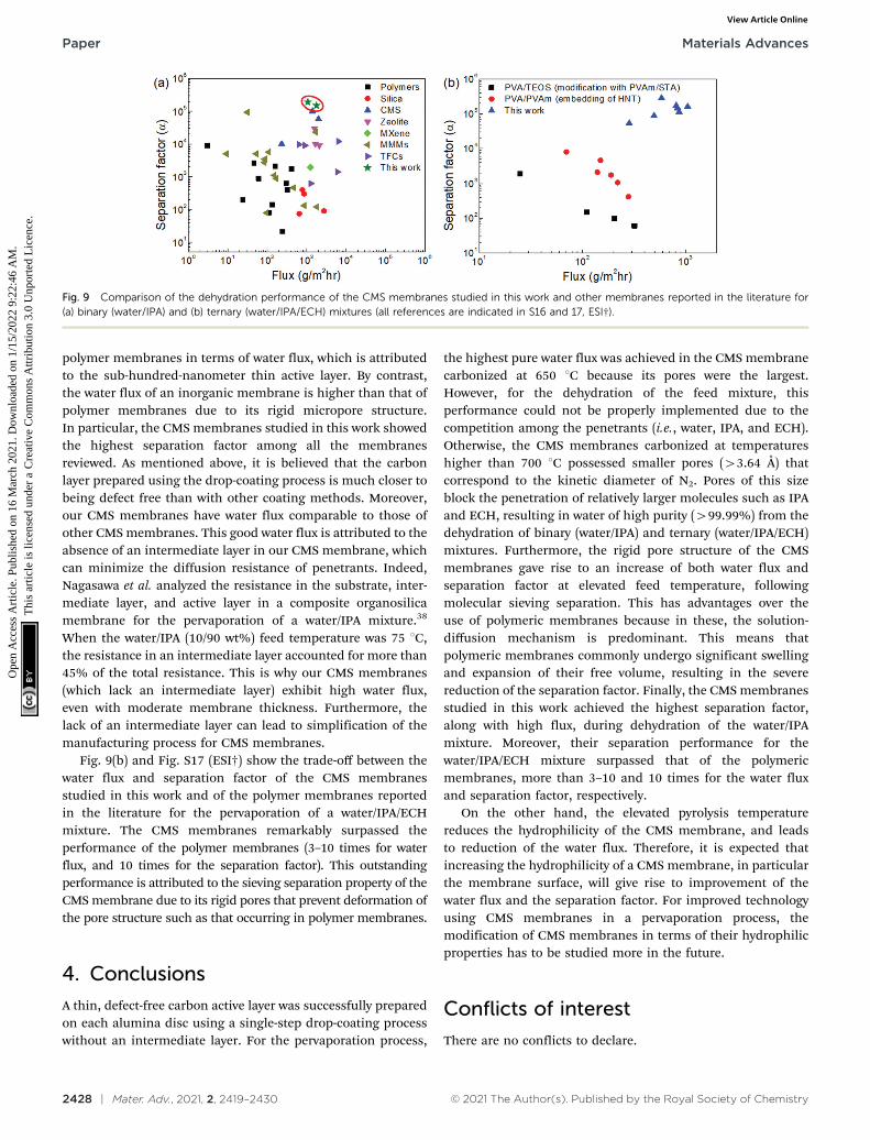
3.4.4 Comparison of separation performance for water/IPAand water/IPA/ECH mixtures. The pervaporation performanceof the CMS membranes studied in this work was comparedwith those of other membranes reported in the literature (seeFig. 9 and Fig. S16–S17, ESI†). Fig. 9(a) and Fig. S16 (ESI†)present the pervaporation performance results for membranesof various kinds (e.g., polymers, silica, CMS, zeolites, transition-metal carbides (MXene), mixed matrix membranes: MMMs,and polyamide thin film composite membranes: TFCs) forthe separation of a water/IPA mixture. The performances ofmost polymer membranes (including MMMs) are below that ofinorganic membranes because the driving force of the non-porous polymer membranes is the chemical potential gradientacross the membrane. This leads to relatively low water flux.Nevertheless, the TFCs surpassed the limitation of the other
Materials Advances Paper
Ope
n A
cces
s A
rtic
le. P
ublis
hed
on 1
6 M
arch
202
1. D
ownl
oade
d on
1/1
5/20
22 9
:22:
46 A
M.
Thi
s ar
ticle
is li
cens
ed u
nder
a C
reat
ive
Com
mon
s A
ttrib
utio
n 3.
0 U
npor
ted
Lic
ence
.View Article Online
2428 | Mater. Adv., 2021, 2, 2419–2430 © 2021 The Author(s). Published by the Royal Society of Chemistry
polymer membranes in terms of water flux, which is attributedto the sub-hundred-nanometer thin active layer. By contrast,the water flux of an inorganic membrane is higher than that ofpolymer membranes due to its rigid micropore structure.In particular, the CMS membranes studied in this work showedthe highest separation factor among all the membranesreviewed. As mentioned above, it is believed that the carbonlayer prepared using the drop-coating process is much closer tobeing defect free than with other coating methods. Moreover,our CMS membranes have water flux comparable to those ofother CMS membranes. This good water flux is attributed to theabsence of an intermediate layer in our CMS membrane, whichcan minimize the diffusion resistance of penetrants. Indeed,Nagasawa et al. analyzed the resistance in the substrate, inter-mediate layer, and active layer in a composite organosilicamembrane for the pervaporation of a water/IPA mixture.38
When the water/IPA (10/90 wt%) feed temperature was 75 1C,the resistance in an intermediate layer accounted for more than45% of the total resistance. This is why our CMS membranes(which lack an intermediate layer) exhibit high water flux,even with moderate membrane thickness. Furthermore, thelack of an intermediate layer can lead to simplification of themanufacturing process for CMS membranes.
Fig. 9(b) and Fig. S17 (ESI†) show the trade-off between thewater flux and separation factor of the CMS membranesstudied in this work and of the polymer membranes reportedin the literature for the pervaporation of a water/IPA/ECHmixture. The CMS membranes remarkably surpassed theperformance of the polymer membranes (3–10 times for waterflux, and 10 times for the separation factor). This outstandingperformance is attributed to the sieving separation property of theCMS membrane due to its rigid pores that prevent deformation ofthe pore structure such as that occurring in polymer membranes.
4. Conclusions
A thin, defect-free carbon active layer was successfully preparedon each alumina disc using a single-step drop-coating processwithout an intermediate layer. For the pervaporation process,
the highest pure water flux was achieved in the CMS membranecarbonized at 650 1C because its pores were the largest.However, for the dehydration of the feed mixture, thisperformance could not be properly implemented due to thecompetition among the penetrants (i.e., water, IPA, and ECH).Otherwise, the CMS membranes carbonized at temperatureshigher than 700 1C possessed smaller pores (43.64 Å) thatcorrespond to the kinetic diameter of N2. Pores of this sizeblock the penetration of relatively larger molecules such as IPAand ECH, resulting in water of high purity (499.99%) from thedehydration of binary (water/IPA) and ternary (water/IPA/ECH)mixtures. Furthermore, the rigid pore structure of the CMSmembranes gave rise to an increase of both water flux andseparation factor at elevated feed temperature, followingmolecular sieving separation. This has advantages over theuse of polymeric membranes because in these, the solution-diffusion mechanism is predominant. This means thatpolymeric membranes commonly undergo significant swellingand expansion of their free volume, resulting in the severereduction of the separation factor. Finally, the CMS membranesstudied in this work achieved the highest separation factor,along with high flux, during dehydration of the water/IPAmixture. Moreover, their separation performance for thewater/IPA/ECH mixture surpassed that of the polymericmembranes, more than 3–10 and 10 times for the water fluxand separation factor, respectively.
On the other hand, the elevated pyrolysis temperaturereduces the hydrophilicity of the CMS membrane, and leadsto reduction of the water flux. Therefore, it is expected thatincreasing the hydrophilicity of a CMS membrane, in particularthe membrane surface, will give rise to improvement of thewater flux and the separation factor. For improved technologyusing CMS membranes in a pervaporation process, themodification of CMS membranes in terms of their hydrophilicproperties has to be studied more in the future.
Conflicts of interest
There are no conflicts to declare.
Fig. 9 Comparison of the dehydration performance of the CMS membranes studied in this work and other membranes reported in the literature for(a) binary (water/IPA) and (b) ternary (water/IPA/ECH) mixtures (all references are indicated in S16 and 17, ESI†).
Paper Materials Advances
Ope
n A
cces
s A
rtic
le. P
ublis
hed
on 1
6 M
arch
202
1. D
ownl
oade
d on
1/1
5/20
22 9
:22:
46 A
M.
Thi
s ar
ticle
is li
cens
ed u
nder
a C
reat
ive
Com
mon
s A
ttrib
utio
n 3.
0 U
npor
ted
Lic
ence
.View Article Online

© 2021 The Author(s). Published by the Royal Society of Chemistry Mater. Adv., 2021, 2, 2419–2430 | 2429
Acknowledgements
This work was supported by the National Research Council ofScience & Technology (NST) grant by the Korea government(MSIP) (No. CRC-14-01-KRICT) and the New & RenewableEnergy Core Technology Program of the Korea Institute ofEnergy Technology Evaluation and Planning (KETEP) grantedfinancial resource from the Ministry of Trade, Industry andEnergy, Republic of Korea (No. 20172010106170).
References
1 F.-L. Jin, X. Li and S.-J. Park, J. Ind. Eng. Chem., 2015, 29,1–11.
2 B. Ellis, Chemistry and Technology of Epoxy Resins, Springer,1993.
3 A. Choudhary and E. Prasad, Allied Market Research, 2020.4 S. Chaudhari, D. Chang, K. Cho, M. Shon, Y. Kwon, S. Nam
and Y. Park, J. Taiwan Inst. Chem. Eng., 2020, 114, 103–114.5 H.-G. Kim, H.-R. Na, H. R. Lee, M. I. Kim, C.-S. Lim and
B. Seo, Sep. Purif. Technol., 2021, 254, 117678.6 S.-J. Wang, D. S.-H. Wong, I. J. Q. Lim, Y.-T. Chen and
C.-C. Huang, Ind. Eng. Chem. Res., 2018, 57, 6926–6936.7 S. Chaudhari, Y. Kwon, M. Shon, S. Nam and Y. Park, RSC
Adv., 2019, 9, 5908–5917.8 G. W. Olsen, S. E. Lacy, S. R. Chamberlin, D. L. Albert,
T. G. Arceneaux, L. F. Bullard, B. A. Stafford andJ. M. Boswell, Am. J. Ind. Med., 1994, 25, 205–218.
9 A. Svang-Ariyaskul, R. Y. M. Huang, P. L. Douglas, R. Pal,X. Feng, P. Chen and L. Liu, J. Membr. Sci., 2006, 280,815–823.
10 R. Castro-Munoz, J. Buera-Gonzalez, O. de la Iglesia,F. Galiano, V. Fıla, M. Malankowska, C. Rubio, A. Figoli,C. Tellez and J. Coronas, J. Membr. Sci., 2019, 582, 423–434.
11 Y. Li, L. H. Wee, J. A. Martens and I. F. J. Vankelecom,J. Mater. Chem. A, 2014, 2, 10034–10040.
12 B. Smitha, D. Suhanya, S. Sridhar and M. Ramakrishna,J. Membr. Sci., 2004, 241, 1–21.
13 X. H. Zhang, Q. L. Liu, Y. Xiong, A. M. Zhu, Y. Chen andQ. G. Zhang, J. Membr. Sci., 2009, 327, 274–280.
14 W. Z. A. W. Jusoh, S. A. Rahman, A. L. Ahmad andN. M. Mokhtar, Applications of Nanotechnology for GreenSynthesis, 2020, pp. 97–124.
15 C. Arregoitia-Sarabia, D. Gonzalez-Revuelta, M. Fallanza,D. Gorri and I. Ortiz, Sep. Purif. Technol., 2020, 117101.
16 A. M. Eliceche, M. C. Daviou, P. M. Hoch and I. O. Uribe,Comput. Chem. Eng., 2002, 26, 563–573.
17 S. S. Hosseini, H. Pahlavanzadeh and M. Tamadondar,Iran. Chem. Eng. J., 2014, 13, 76–84.
18 M. E. Dmitrenko, A. V. Penkova, A. I. Kuzminova,M. Morshed, M. I. Larionov, H. Alem, A. A. Zolotarev,S. S. Ermakov and D. Roizard, Appl. Surf. Sci., 2018, 450,527–537.
19 A. V. Penkova, M. E. Dmitrenko, N. A. Savon, A. B. Missyul,A. S. Mazur, A. I. Kuzminova, A. A. Zolotarev, V. Mikhailovskii,
E. Lahderanta and D. A. Markelov, Sep. Purif. Technol., 2018,204, 1–12.
20 M. Ghazali, M. Nawawi and R. Y. M. Huang, J. Membr. Sci.,1997, 124, 53–62.
21 K. S. Sportsman, J. D. Way, W.-J. Chen, G. P. Pez andD. V. Laciak, J. Membr. Sci., 2002, 203, 155–166.
22 H.-A. Tsai, Y.-L. Ye, K.-R. Lee, S.-H. Huang, M.-C. Suen andJ.-Y. Lai, J. Membr. Sci., 2011, 368, 254–263.
23 J. Sekulic, M. W. J. Luiten, J. E. Ten Elshof, N. E. Benes andK. Keizer, Desalination, 2002, 148, 19–23.
24 C. Yu, C. Zhong, Y. Liu, X. Gu, G. Yang, W. Xing and N. Xu,Chem. Eng. Res. Des., 2012, 90, 1372–1380.
25 V. S. Praptowidodo, J. Mol. Struct., 2005, 739, 207–212.26 T. A. Peters, C. H. S. Poeth, N. E. Benes, H. Buijs, F. F. Vercauteren
and J. T. F. Keurentjes, J. Membr. Sci., 2006, 276, 42–50.27 S. Chaudhari, Y. Kwon, M. Shon, S. Nam and Y. Park, J. Ind.
Eng. Chem., 2020, 81, 185–195.28 P. H. T. Ngamou, M. E. Ivanova, O. Guillon and
W. A. Meulenberg, J. Mater. Chem. A, 2019, 7, 7082–7091.29 S. Sommer and T. Melin, Chem. Eng. Process., 2005, 44,
1138–1156.30 Z. Pan, F. Yu, L. Li, M. Liu, C. Song, J. Yang, H. Li, C. Wang,
Y. Pan and T. Wang, Sep. Purif. Technol., 2020, 116948.31 N. Tahri, I. Jedidi, S. Ayadi, S. Cerneaux, M. Cretin and
R. Ben Amar, Desalin. Water Treat., 2016, 57, 23473–23488.32 S. Tanaka, T. Yasuda, Y. Katayama and Y. Miyake, J. Membr.
Sci., 2011, 379, 52–59.33 Y.-R. Dong, M. Nakao, N. Nishiyama, Y. Egashira and
K. Ueyama, Sep. Purif. Technol., 2010, 73, 2–7.34 K.-S. Liao, Y.-J. Fu, C.-C. Hu, J.-T. Chen, D.-W. Lin, K.-R. Lee,
K.-L. Tung, Y. C. Jean and J.-Y. Lai, Carbon, 2012, 50,4220–4227.
35 P. S. Tin, H. Y. Lin, R. C. Ong and T.-S. Chung, Carbon, 2011,49, 369–375.
36 M. Yoshimune, K. Mizoguchi and K. Haraya, J. Membr. Sci.,2013, 425, 149–155.
37 Y. Sakata, A. Muto, M. A. Uddin and H. Suga, Sep. Purif.Technol., 1999, 17, 97–100.
38 H. Nagasawa, N. Matsuda, M. Kanezashi, T. Yoshioka andT. Tsuru, J. Membr. Sci., 2016, 498, 336–344.
39 J. Shao, Z. Zhan, J. Li, Z. Wang, K. Li and Y. Yan, J. Membr.Sci., 2014, 451, 10–17.
40 S.-J. Kim, P. S. Lee, J.-S. Chang, S.-E. Nam and Y.-I. Park, Sep.Purif. Technol., 2018, 194, 443–450.
41 S. Chaudhari, M. Baek, Y. Kwon, M. Shon, S. Nam andY. Park, Appl. Surf. Sci., 2019, 493, 193–201.
42 Y. Wu, F. Wang, B. Zhang, D. Zhao, T. Wang and J. Qiu, Asia-Pac. J. Chem. Eng., 2018, 13, e2251.
43 B. Zhang, Y. Shi, Y. Wu, T. Wang and J. Qiu, J. Appl. Polym.Sci., 2014, 131, 39925.
44 X. Zhang, B. Zhang, Y. Wu, D. Wang and T. Wang, J. Appl.Polym. Sci., 2017, 134, 44889.
45 C. A. Scholes and U. K. Ghosh, Membranes, 2017, 7, 9.46 Y. Xiao, M. L. Chng, T.-S. Chung, M. Toriida, S. Tamai,
H. Chen and Y. C. J. Jean, Carbon, 2010, 48, 408–416.47 B. T. Low and T. S. Chung, Carbon, 2011, 49, 2104–2112.
Materials Advances Paper
Ope
n A
cces
s A
rtic
le. P
ublis
hed
on 1
6 M
arch
202
1. D
ownl
oade
d on
1/1
5/20
22 9
:22:
46 A
M.
Thi
s ar
ticle
is li
cens
ed u
nder
a C
reat
ive
Com
mon
s A
ttrib
utio
n 3.
0 U
npor
ted
Lic
ence
.View Article Online

2430 | Mater. Adv., 2021, 2, 2419–2430 © 2021 The Author(s). Published by the Royal Society of Chemistry
48 A. K. Itta and H.-H. Tseng, Int. J. Hydrogen Energy, 2011, 36,8645–8657.
49 C.-L. Liu, W.-S. Dong, J.-R. Song and L. Liu, Mater. Sci. Eng.,A, 2007, 459, 347–354.
50 S. Tanaka, N. Nakatani, A. Doi and Y. Miyake, Carbon, 2011,49, 3184–3189.
51 F. Y. Li and T.-S. Chung, Int. J. Hydrogen Energy, 2013, 38,9786–9793.
52 D. Van Baelen, B. Van der Bruggen, K. Van den Dungen, J. Degreveand C. Vandecasteele, Chem. Eng. Sci., 2005, 60, 1583–1590.
53 Y. Kwon, S. Chaudhari, C. Kim, D. Son, J. Park, M. Moon,M. Shon, Y. Park and S. Nam, RSC Adv., 2018, 8, 20669–20678.
54 P. D. Chapman, T. Oliveira, A. G. Livingston and K. Li,J. Membr. Sci., 2008, 318, 5–37.
55 S. G. Adoor, B. Prathab, L. S. Manjeshwar andT. M. Aminabhavi, Polymer, 2007, 48, 5417–5430.
56 X. Feng and R. Y. M. Huang, Ind. Eng. Chem. Res., 1997, 36,1048–1066.
57 C.-Y. Tu, Y.-L. Liu, K.-R. Lee and J.-Y. Lai, J. Membr. Sci.,2006, 274, 47–55.
58 H. G. Premakshi, A. M. Sajjan and M. Y. Kariduraganavar,J. Mater. Chem. A, 2015, 3, 3952–3961.
59 M. Amirilargani, M. A. Tofighy, T. Mohammadi andB. Sadatnia, Ind. Eng. Chem. Res., 2014, 53, 12819–12829.
Paper Materials Advances
Ope
n A
cces
s A
rtic
le. P
ublis
hed
on 1
6 M
arch
202
1. D
ownl
oade
d on
1/1
5/20
22 9
:22:
46 A
M.
Thi
s ar
ticle
is li
cens
ed u
nder
a C
reat
ive
Com
mon
s A
ttrib
utio
n 3.
0 U
npor
ted
Lic
ence
.View Article Online