ultra low emission technology innovations for …
TRANSCRIPT

The ULTIMATE project is funded by the European Union H2020 programme under GA no. 633436.
ULTRA LOW EMISSION TECHNOLOGY INNOVATIONS FOR MID-CENTURY AIRCRAFT TURBINE ENGINES
Tomas GrönstedtChalmers University, Sweden
Carlos XistoChalmers University, Sweden
Vishal SethiCranfield University, United Kingdom
Andrew RoltCranfield University, United Kingdom
Nicolás García RosaISAE, France
Arne SeitzBauhaus Luftfahrt e.V., Germany
Kyros YakinthosAristotle University of Thessaloniki, Greece
Stefan DonnerhackMTU Aero Engines AG, Germany
Paul NewtonRolls-Royce plc, United Kingdom
Nicholas TantotSNECMA, France
Oliver SchmitzARTTIC, Germany
Anders LundbladhGKN Aerospace, Sweden

• Irreversibility
o Categorizing losses: ”the big three”
• Project objectives and approach
• ULTIMATE technologies
• Impact
The ULTIMATE project - talk in short
12/10/2016 2FT2016

3
The ULTIMATE project consortium
ULTIMATE Consortium
GKN
RR
MTU
SN
ART BHL
CHALM
AUTH
ISAE
Industry SMEs UniversitiesResearch
CU
12/10/2016 FT2016

The jet engine
4
addedQ
hotV
coldV
inletTinletexitTexit hmhmWQ ,,
First law (open system, stationary, single inflowsingle outflow) gz
VhhT
2
2
added
o
QpowerPropulsive
12/10/2016 FT2016

Second law
5
LT
T
Qmsms
surr
r r
r
IN
ii
OUT
ee
.powerLost
0generationEntropy
11, sm
22 , sm
33, sm
1Q
2Q
.surrT
12/10/2016 FT2016

One needs to attack the “the Big Three”– Combustor irreversibilities (1)
– Core exhaust heat losses (2)
– Excess of kinetic energy in the bypass flow (3)
The red cross-hatched areas may be captured – HOW ???
Losses in a 2015 state-of-the-art
turbofan
Exergy, denoted ε, of a steady stream of matter is equal to
the maximum amount of work obtainable when the stream is brought from its initial state to
a state of thermal and mechanical equilibrium
with its environment.
Grönstedt, T., Irannezhad, M., Lei, X., Thulin, O., Lundbladh, A., “First and second law analysis of future aircraft engines”. Journal of Engineering for Gas Turbines and Power”, 136 (3), 2014

7
Project mission and objectives
Major challenge (all relative to the year 2000)
75% reduction in CO2
90% reduction in NOx during cruise
Reduction of noise by 15 dB
Initial ULTIMATE SRIA 2050 CO2 target breakdown
ULTIMATE Alone18% reduction in CO2
20% reduction in NOx during cruise
3 dB reduction in Noise
Develop propulsion “systemsconcepts” with the potential to fulfil the SRIA 2050 key challenges
12/10/2016 FT2016

Propulsion systems with a SRIA 2050 target potential
12/10/2016 FT2016

9
Concept and approach
Exploit synergies between radical engine configurations
Constant volume type
combustion.
Bottoming cycles
Intercooling & recuperation
Advanced low pressure system technology
12/10/2016 FT2016
10
Concept and approach
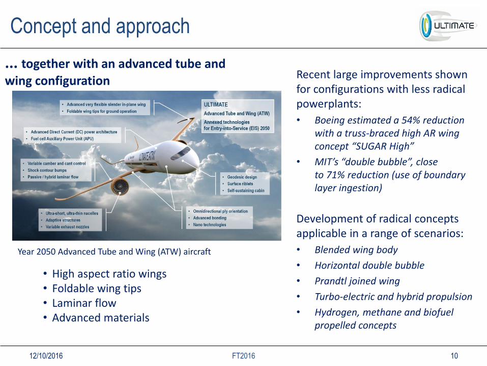
... together with an advanced tube and
wing configuration
Year 2050 Advanced Tube and Wing (ATW) aircraft
Recent large improvements shownfor configurations with less radical powerplants:
• Boeing estimated a 54% reduction with a truss-braced high AR wing concept “SUGAR High”
• MIT’s “double bubble”, closeto 71% reduction (use of boundarylayer ingestion)
Development of radical concepts applicable in a range of scenarios:
• Blended wing body
• Horizontal double bubble
• Prandtl joined wing
• Turbo-electric and hybrid propulsion
• Hydrogen, methane and biofuel propelled concepts
• High aspect ratio wings• Foldable wing tips• Laminar flow• Advanced materials
12/10/2016 FT2016

11
Loss source 1 - combustor irreversibility
Attacking loss source #1
Piston based
composite cycles
Nutating disc
Pulse detonation
combustion
a) Piston based “composite cycle” b) Pulse detonation core c) Nutating disc
b)c)
a)
Gas work potential
Shaft power
Both
A Composite Cycle Engine Concept with Hecto-Pressure Ratio, AIAA 2015-4028, Kaiser, Seitz, Donnerhack, Lundbladh
12/10/2016 FT2016

12
Source 1 – historical achievements

13
Already achieved outside ULTIMATE project (LEMCOTEC)
- 18% specific fuel consumption
+ 30% weight increase
- 15% fuel burn S. Kaiser, S. Donnerhack, A. Lundbladh, A. Seitz, ”A Composite Cycle Engine Concept with Hecto-Pressure Ratio", 51st AIAA/SAE/ASEE Joint Propulsion Conference, Propulsion and Energy Forum, (AIAA 2015-4028).
Source 1 - The composite cycle
12/10/2016 FT2016
14
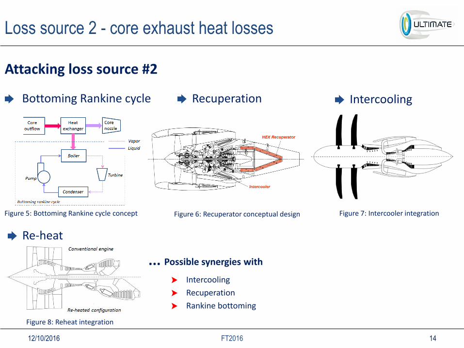
Loss source 2 - core exhaust heat losses
Attacking loss source #2
Bottoming Rankine cycle Recuperation Intercooling
Re-heat
Figure 6: Recuperator conceptual design Figure 5: Bottoming Rankine cycle concept Figure 7: Intercooler integration
Figure 8: Reheat integration
... Possible synergies with
Intercooling
Recuperation
Rankine bottoming
12/10/2016 FT2016

15
• Alternative recuperation• Staged heat recovery (SHR)• HEX between IPT-LPT and downstream LPT• Concept for compact heat exchange
• Secondary fluid systemsin recuperation concepts
Recuperation
Recuperator conceptual design
Intercooling• Possibly harvesting rejected heat
with secondary fluid system
Loss source 2 - core exhaust heat losses
12/10/2016 FT2016

16
Attacking loss source #3ultra-thin adaptive inlet
adaptive external shapes
circumferentially retractable concepts
variable pitch fan rotors,
variable bypass and core nozzles, variable inlet guide vanes
Powerplant for intercontinental configuration (the Rolls-Royce UltraFan concept for 2025 is used to illustrate this configuration)
Retractable nacelle concept
Intra-European configuration
Open-Rotor architecture for the Intra-European configuration Geared architecture for the intercontinental configuration
Loss source 3 – excess kinetic energy
12/10/2016 FT2016
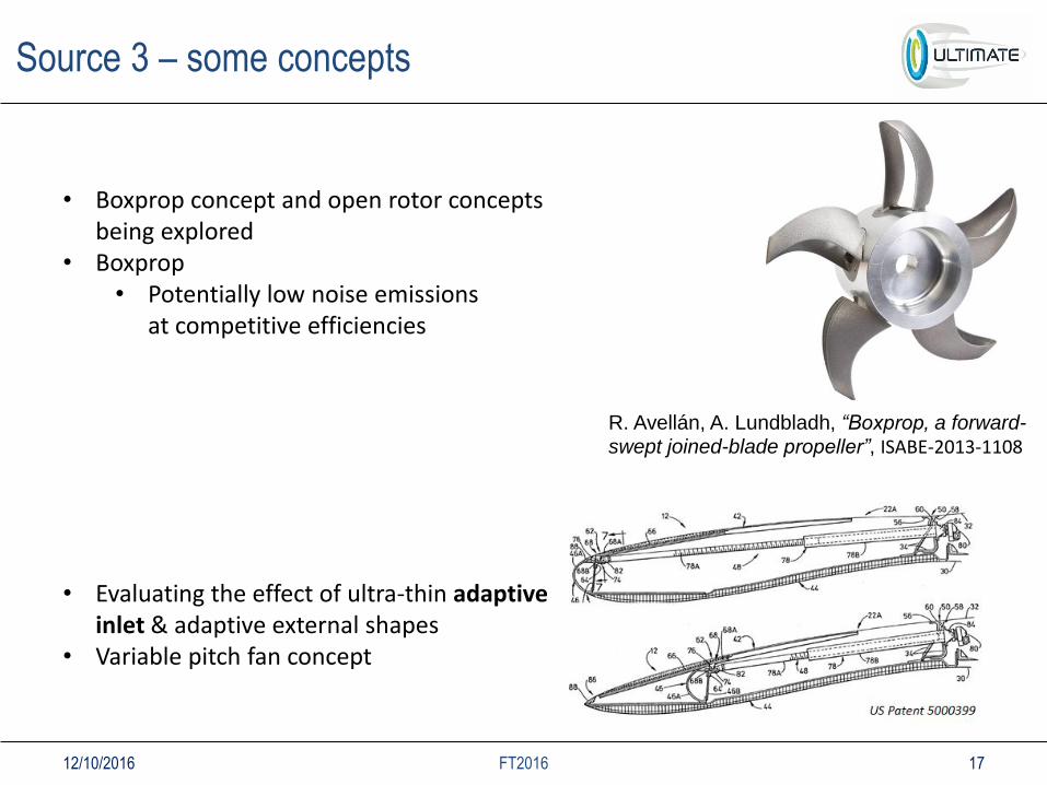
Source 3 – some concepts
17
• Evaluating the effect of ultra-thin adaptive inlet & adaptive external shapes
• Variable pitch fan concept
R. Avellán, A. Lundbladh, “Boxprop, a forward-
swept joined-blade propeller”, ISABE-2013-1108
• Boxprop concept and open rotor conceptsbeing explored
• Boxprop• Potentially low noise emissions
at competitive efficiencies
12/10/2016 FT2016

18
The search for ultra low emission engines
Communication and exploitation
Composite piston topping
Rankine bottoming
Alternative technology
Configuration mix and matchexplore synergies
Technologydevelopment
Nutating disc topping
+Rankine
bottoming
Additionalconfigurations
• Technology downselection
• Share technology simulators
• Common technology parameter assumptions
Configurationassessment
• Multidisciplinaryevaluationplatform
• Aircraft missionanalysis
• SRIA 2050optimization
• Technologyparameter refinement
Pulse detonation
topping +
Intercooling
Technologyfeasibility
Technologyparameters
Composite piston
topping+
Intercooledrecuperation
Advanced integration and propulsor configurations
Ind
ust
ria
l pa
rtn
er e
xper
tise
Preferred configurations
Configurationfeasibility
Year 2050reference
Industry lead:
• Roadmapping and exploitation• SRIA and scenario evaluation
Po
wer
pla
nt
co
nfi
g.
1
Po
wer
pla
nt
co
nfi
g.
2
Po
wer
pla
nt
co
nfi
g.
3
con
fig
. #n
Developmentpartially qualitative selection
Optimization towards the SRIA 2050 targets
Exploitation
Figure 13. ULTIMATE technology screening and development process
12/10/2016 FT2016

Quantitative metric for technology ranking
19
Specific Range (SR) – distance flown per unit weight of fuel burned
Capture the most critical system performance aspects while avoiding a full mission analysis
𝑆𝑅 = 𝑎M𝐿𝐷
𝑆𝐹𝐶 ⋅ 𝑊
• 𝑎 – Speed of sound• M – Mach number• 𝐿/𝐷 – Lift to Drag ratio• 𝑊 – Weight• 𝑆𝐹𝐶 – Specific Fuel Consumption
12/10/2016 FT2016
20
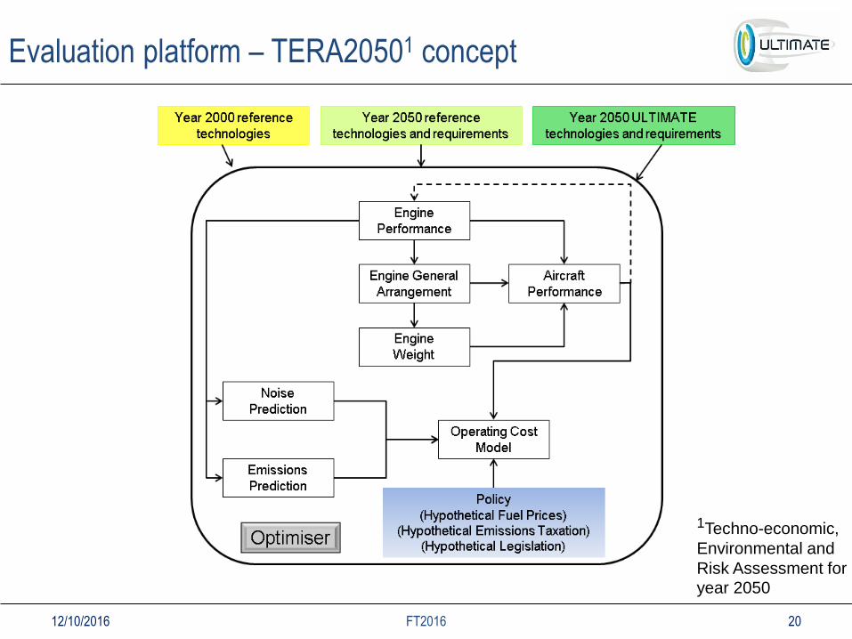
Evaluation platform – TERA20501 concept
1Techno-economic,
Environmental and
Risk Assessment for year 2050
12/10/2016 FT2016

Impact
21
• Y2050 introduction
• Potential reduction
from ULTIMATE
technologies
o 3 billion tonnes of
CO2 reduction in
the 25 years beyond
entry into service
12/10/2016 FT2016

Ultimate in the news…
22
Two pager in flight international (20th of Sept.)
12/10/2016 FT2016
• Great potential exist to improve cycle efficiency with
advanced core concepts
• A categorization of losses based on a ”lost work potential” was used for
radical powerplantso A process for down-selection based on the categorization and specific range
• Several advanced core engine concepts outlinedo Concepts for integration with more efficient and silent propulsors discussed
Summary
FT2016 2312/10/2016