ultra-silent series model dca-70usi -...
TRANSCRIPT

PARTS AND OPERATION MANUALOPERATION AND PARTS MANUAL
Revision #1 (04/22/05)
THIS MANUAL MUST ACCOMPANYTHE EQUIPMENT AT ALL TIMES.
ULTRA-SILENTTM SERIESMODEL DCA-70USI
50 Hz GENERATORPARTS LIST NO. M2900000314

PAGE 2 — DCA-70USI (50 Hz) — OPERATION AND PARTS MANUAL — REV. #1 (04/22/05)
DCA-70USI (50 Hz) — OPERATION AND PARTS MANUAL — REV. #1 (04/22/05) — PAGE 3
1
© COPYRIGHT 2005, MULTIQUIP INC.
MQ Power Inc, Ultra-Silent series, and the MQ Power logo are registered trademarks of Multiquip Inc. and may not be used,reproduced, or altered without written permission. All other trademarks are the property of thier respective owners and used withpermission.
This manual MUST accompany the equipment at all times. This manual is considered a permanent part of the equipment andshould remain with the unit if resold.
The information and specifications included in this publication were in effect at the time of approval for printing. Illustrations arebased on the DCA-70USI (50 Hz) Ultra Silent Generator. Multiquip Inc. reserves the right to discontinue or change specifications,design or the information published in this publication at any time without notice and without incurring any obligations.
To find the latest revision of thispublication, visit our website at:
www.mqpower.com
HERE'S HOW TO GET HELPPLEASE HAVE THE MODEL AND SERIAL
NUMBER ON-HAND WHEN CALLINGMQ POWER CORPORATE OFFICE18910 Wilmington Ave. 800-421-1244Carson, CA 90746 FAX: 310-632-2656Email: [email protected]: www.mqpower.comPARTS DEPARTMENT800-427-1244 FAX: 800-672-7877310-537-3700 FAX: 310-637-3284SERVICE DEPARTMENT800-835-2551 FAX: 310-638-8046310-537-3700TECHNICAL ASSISTANCE800-835-2551 FAX: 310-638-8046WARRANTY DEPARTMENT800-835-2551, EXT. 279 FAX: 310-638-8046310-537-3700, EXT. 279
PAGE 4 — DCA-70USI (50 Hz) — OPERATION AND PARTS MANUAL — REV. #1 (04/22/05)
TABLE OF CONTENTS
Specification and partnumber are subject tochange without notice.
NOTE
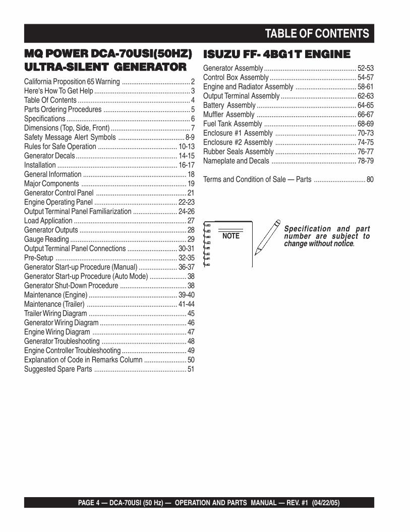
MQ POWER DCA-70USI(50HZ)MQ POWER DCA-70USI(50HZ)MQ POWER DCA-70USI(50HZ)MQ POWER DCA-70USI(50HZ)MQ POWER DCA-70USI(50HZ)ULULULULULTRA-SILENT GENERATRA-SILENT GENERATRA-SILENT GENERATRA-SILENT GENERATRA-SILENT GENERATORTORTORTORTORCalifornia Proposition 65 Warning ..................................... 2Here's How To Get Help .................................................... 3Table Of Contents ............................................................. 4Parts Ordering Procedures ............................................... 5Specifications ................................................................... 6Dimensions (Top, Side, Front) ........................................... 7Safety Message Alert Symbols .................................... 8-9Rules for Safe Operation ........................................... 10-13Generator Decals ....................................................... 14-15Installation ................................................................. 16-17General Information ........................................................ 18Major Components ......................................................... 19Generator Control Panel ................................................. 21Engine Operating Panel ............................................. 22-23Output Terminal Panel Familiarization ........................ 24-26Load Application ............................................................. 27Generator Outputs .......................................................... 28Gauge Reading ............................................................... 29Output Terminal Panel Connections ........................... 30-31Pre-Setup .................................................................. 32-35Generator Start-up Procedure (Manual) ..................... 36-37Generator Start-up Procedure (Auto Mode) .................... 38Generator Shut-Down Procedure .................................... 38Maintenance (Engine) ................................................ 39-40Maintenance (Trailer) ................................................. 41-44Trailer Wiring Diagram ..................................................... 45Generator Wiring Diagram ............................................... 46Engine Wiring Diagram ................................................... 47Generator Troubleshooting .............................................. 48Engine Controller Troubleshooting ................................... 49Explanation of Code in Remarks Column ....................... 50Suggested Spare Parts .................................................. 51
Generator Assembly .................................................. 52-53Control Box Assembly ............................................... 54-57Engine and Radiator Assembly ................................. 58-61Output Terminal Assembly ......................................... 62-63Battery Assembly ...................................................... 64-65Muffler Assembly ...................................................... 66-67Fuel Tank Assembly .................................................. 68-69Enclosure #1 Assembly ............................................ 70-73Enclosure #2 Assembly ............................................ 74-75Rubber Seals Assembly ............................................ 76-77Nameplate and Decals .............................................. 78-79
Terms and Condition of Sale — Parts ............................ 80
ISUZU FF- 4BG1T ENGINEISUZU FF- 4BG1T ENGINEISUZU FF- 4BG1T ENGINEISUZU FF- 4BG1T ENGINEISUZU FF- 4BG1T ENGINE

DCA-70USI (50 Hz) — OPERATION AND PARTS MANUAL — REV. #1 (04/22/05) — PAGE 5
1
MQPOWERA Division of Multiquip Inc.POST OFFICE BOX 6254CARSON, CA 90749310-537-3700 • 800-421-1244FAX: 310-632-2656E-MAIL: [email protected]: www.mqpower.com
When ordering parts,please supply the following information:
❒❒❒❒❒ Dealer account number❒❒❒❒❒ Dealer name and address❒❒❒❒❒ Shipping address (if different than billing address)❒❒❒❒❒ Return fax number❒❒❒❒❒ Applicable model number❒❒❒❒❒ Quantity, part number and description of each part❒❒❒❒❒ Specify preferred method of shipment:
✓ FedEx or UPS Ground✓ FedEx or UPS Second Day or Third Day✓ FedEx or UPS Next Day✓ Federal Express Priority One✓ DHL✓ Truck
Note: Unless otherwise indicated by customer, allorders are treated as “Standard Orders”, and willship within 24 hours. We will make every effort toship “Air Shipments” the same day that the order isreceived, if prior to 2PM west coast time. “StockOrders” must be so noted on fax or web forms.
Extra Discounts!All parts orders which include complete part numbers andare received by our automated web parts order system, orby fax qualify for the following extra discounts:
Ordered Standard Stock ordersvia orders ($750 list and above)
Fax 3% 10%
Web 5% 10%
Special freight allowanceswhen you order 10 or moreline items via Web or Fax!**FedEx Ground Service at no charge for freightNo other allowances on freight shipped by any other carrier.**Common nuts, bolts and washers (all items under $1.00list price) do not count towards the 10+ line items.
Place Your Parts Order Via Web or FaxFor Even More Savings!
(Domestic USA Dealers Only)
NOTE: DISCOUNTS ARE SUBJECT TO CHANGE
Here’s how to get help...Please have the model and serial numberon hand when calling.
MQ POWER CORPORATE OFFICE18910 Wilmington Ave. 800-421-1244Carson, CA 90746 FAX: 310-632-2656Email: [email protected]: www.mqpower.comPARTS DEPARTMENT800-427-1244 FAX: 800-672-7877310-537-3700 FAX: 310-637-3284SERVICE DEPARTMENT800-835-2551 FAX: 310-638-8046310-537-3700TECHNICAL ASSISTANCE800-835-2551 FAX: 310-638-8046WARRANTY DEPARTMENT800-835-2551, EXT. 279 FAX: 310-638-8046310-537-3700, EXT. 279
Direct TOLL-FREE accessto our Parts Department:
Toll-free nationwide — 800-427-1244
Toll-free FAX — 800-6-PARTS-7 (800/672-7877)
PARTS ORDERING PROCEDURES

PAGE 6 — DCA-70USI (50 Hz) — OPERATION AND PARTS MANUAL — REV. #1 (04/22/05)
DCA-70USI (50 Hz) — SPECIFICATIONS
snoitacificepSrotareneG.1elbaT
ledoM ISU07-ACD
epyT ,detalitnevfles,dleifgnivloveRrotarenegsuonorhcnysepytdetcetorpnepo
noitcennoCerutamrA lartueNhtiwratS gaZgiZ
esahP 3 elgniS
tuptuOybdnatS )WK4.05(AVK0.36 WK63
tuptuOemirP )WK84(AVK06 WK6.43
egatloV V004roV002 V001/002
ycneuqerF zH05
deepS mpr0051
rotcaFrewoP 8.0 1
rewoPCA.xuA zH06,esahPelgniS
egatloV V001
tuptuO )2xWK4.2(WK8.4
snoitacificepSenignE.2elbaT
ledoM T1GB4-FFUZUSI
epyT degrahc-obrut,noitcejnitcerid,delooc-retaw,elcyc4
srednilyCfo.oN srednilyc4
ekortSxeroB )mm521xmm501(.ni29.4x.ni31.4
tnemecalpsiD )cc923,4(.ni.uc462
gnitratS CDV21cirtcelE
yticapaCtnalooC )sretil4.41(.lag08.3
yticapaCliOebuL )sretil2.31(.lag94.3
epyTleuF leuFleseiD2#
yticapaCknaTleuF )sretil093(.lag301
noitpmusnoCleuF tarh/)L0.31(.lag4.3 daollluf
yrettaB 1x)A007FOACC(72
DCA-70USI (50 Hz) — OPERATION AND PARTS MANUAL — REV. #1 (04/22/05) — PAGE 7
1
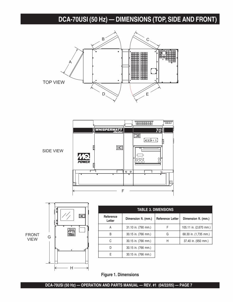
DCA-70USI (50 Hz) — DIMENSIONS (TOP, SIDE AND FRONT)
Figure 1. Dimensions
SNOISNEMID.3ELBAT
ecnerefeRretteL
).mm(.tfnoisnemiD retteLecnerefeR ).mm(.tfnoisnemiD
A ).mm097(.ni01.13 F ).mm076,2(.ni11.501
B ).mm667(.ni51.03 G ).mm537,1(.ni03.86
C ).mm667(.ni51.03 H ).mm059(.ni04.73
D ).mm667(.ni51.03
E ).mm667(.ni51.03

PAGE 8 — DCA-70USI (50 Hz) — OPERATION AND PARTS MANUAL — REV. #1 (04/22/05)
This Owner's Manual has beendeveloped to provide completeinstructions for the safe andefficient operation of theMQ Power Model DCA-70USIUltra Silent™ Generator.
Before using this generator, ensure that the operatingindividual has read and understands all instructions inthis manual.
Safety precautions should be followed at all times whenoperating this equipment. Failure to read and understand theSafety Messages and Operating Instructions could result ininjury to yourself and others.
FOR YOUR SAFETY AND THE SAFETY OF OTHERS! HAZARD SYMBOLS
Potential hazards associated with the operation of thisequipment will be referenced with "Hazard Symbols" whichappear throughout this manual, and will be referenced inconjunction with Safety "Message Alert Symbols".
NOTE
DCA- 70USI (50 Hz) — SAFETY MESSAGE ALERT SYMBOLS
SAFETY MESSAGE ALERT SYMBOLS
The three (3) Safety Messages shown below will inform youabout potential hazards that could injure you or others. TheSafety Messages specifically address the level of exposureto the operator, and are preceded by one of three words:DANGER, WARNING, or CAUTION.
You WILL be KILLED or SERIOUSLY injured if youdo not follow directions.
You COULD be KILLED or SERIOUSLY injured ifyou do not follow directions.
You CAN be injured if you do not follow directions
Gasoline engine exhaust gases containpoisonous carbon monoxide. This gas iscolorless and odorless, and can causeDEATH if inhaled. NEVER operate this
equipment in a confined area or enclosed structure thatdoes not provide ample free flow air.
Gasoline is extremely flammable, andits vapors can cause an explosion ifignited. DO NOT start the engine nearspilled fuel or combustible fluids.DO NOT fill the fuel tank while the engineis running or hot.
DO NOT overfill tank, since spilled fuel could ignite if itcomes into contact with hot engine parts or sparks fromthe ignition system. Store fuel in approved containers, inwell-ventilated areas and away from sparks and flames.NEVER use fuel as a cleaning agent.
Engine components can generate extremeheat. To prevent burns, DO NOT touch theseareas while the engine is running orimmediately after operations. NEVERoperate the engine with heat shields or heatguards removed.
WARNING
DANGER
CAUTION
WARNING - LETHAL EXHAUST GASES
WARNING - BURN HAZARDS
WARNING - EXPLOSIVE FUEL
During operation of this generator, thereexists the possibility of electrocution,electrical shock or burn, which can causesevere bodily harm or even DEATH!
DANGER - ELECTROCUTION HAZARDS
DCA-70USI (50 Hz) — OPERATION AND PARTS MANUAL — REV. #1 (04/22/05) — PAGE 9
1
DCA- 70USI (50 Hz) — SAFETY MESSAGE ALERT SYMBOLS
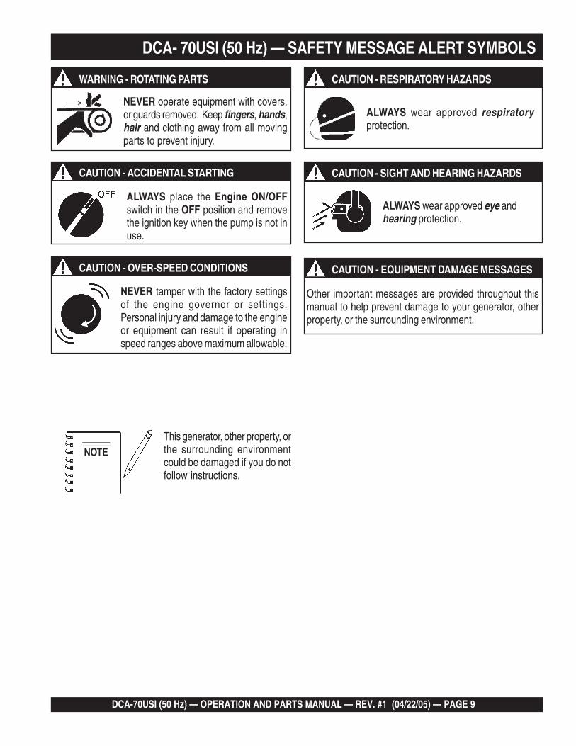
ALWAYS place the Engine ON/OFFswitch in the OFF position and removethe ignition key when the pump is not inuse.
ALWAYS wear approved respiratoryprotection.
ALWAYS wear approved eye andhearing protection.
Other important messages are provided throughout thismanual to help prevent damage to your generator, otherproperty, or the surrounding environment.
This generator, other property, orthe surrounding environmentcould be damaged if you do notfollow instructions.
NOTE
NEVER tamper with the factory settingsof the engine governor or settings.Personal injury and damage to the engineor equipment can result if operating inspeed ranges above maximum allowable.
CAUTION - OVER-SPEED CONDITIONS
CAUTION - ACCIDENTAL STARTING
CAUTION - RESPIRATORY HAZARDS
CAUTION - SIGHT AND HEARING HAZARDS
CAUTION - EQUIPMENT DAMAGE MESSAGES
NEVER operate equipment with covers,or guards removed. Keep fingers, hands,hair and clothing away from all movingparts to prevent injury.
WARNING - ROTATING PARTS
PAGE 10 — DCA-70USI (50 Hz) — OPERATION AND PARTS MANUAL — REV. #1 (04/22/05)
DCA-70USI (50 Hz) — RULES FOR SAFE OPERATION
The following safety guidelines should always be used whenoperating the DCA-70USI Ultra Silent™ Generator.
General Safety:
■ DO NOT operate or service thisequipment before reading this entiremanual.
The operator MUST BE familiar with proper safetyprecautions and operations techniques before usinggenerator.
■ This equipment should not be operated by persons under18 years of age.
■ NEVER operate this equipment without proper protectiveclothing, shatterproof glasses, steel-toed boots and otherprotective devices required by the job.
■ NEVER operate this equipment when notfeeling well due to fatigue, illness or takingmedicine.
■ NEVER operate this equipment under the influence ordrugs or alcohol.
■ NEVER use accessories or attachments, which are notrecommended by MQ Power for this equipment. Damageto the equipment and/or injury to user may result.
■ Manufacturer does not assume responsibility for anyaccident due to equipment modifications. Unauthorizedequipment modification will void all warranties.
■ Whenever necessary, replace nameplate, operation andsafety decals when they become difficult read.
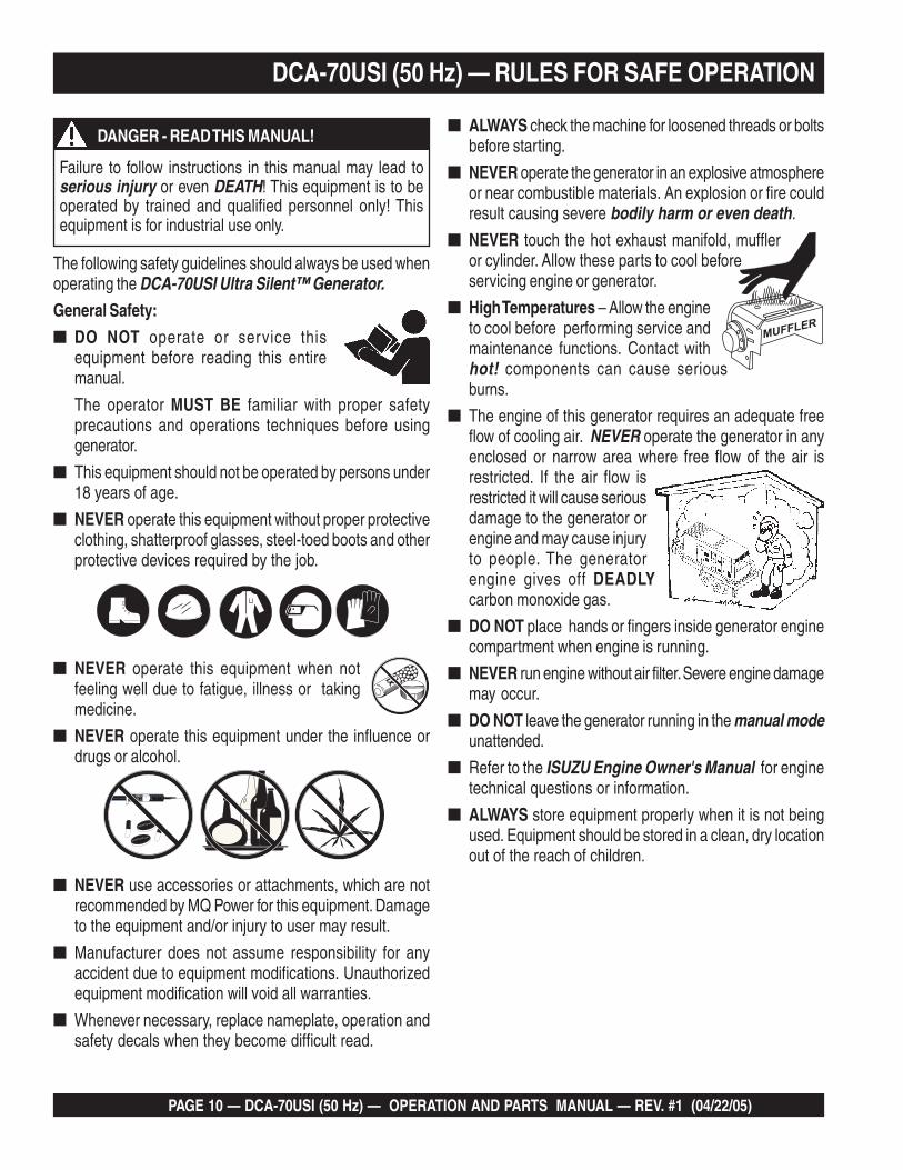
Failure to follow instructions in this manual may lead toserious injury or even DEATH! This equipment is to beoperated by trained and qualified personnel only! Thisequipment is for industrial use only.
DANGER - READ THIS MANUAL!■ ALWAYS check the machine for loosened threads or bolts
before starting.
■ NEVER operate the generator in an explosive atmosphereor near combustible materials. An explosion or fire couldresult causing severe bodily harm or even death.
■ NEVER touch the hot exhaust manifold, muffleror cylinder. Allow these parts to cool beforeservicing engine or generator.
■ High Temperatures – Allow the engineto cool before performing service andmaintenance functions. Contact withhot! components can cause seriousburns.
■ The engine of this generator requires an adequate freeflow of cooling air. NEVER operate the generator in anyenclosed or narrow area where free flow of the air isrestricted. If the air flow isrestricted it will cause seriousdamage to the generator orengine and may cause injuryto people. The generatorengine gives off DEADLYcarbon monoxide gas.
■ DO NOT place hands or fingers inside generator enginecompartment when engine is running.
■ NEVER run engine without air filter. Severe engine damagemay occur.
■ DO NOT leave the generator running in the manual modeunattended.
■ Refer to the ISUZU Engine Owner's Manual for enginetechnical questions or information.
■ ALWAYS store equipment properly when it is not beingused. Equipment should be stored in a clean, dry locationout of the reach of children.

DCA-70USI (50 Hz) — OPERATION AND PARTS MANUAL — REV. #1 (04/22/05) — PAGE 11
1
DCA-70USI (50 Hz) — RULES FOR SAFE OPERATION
POWERCORD
(POWER ON)
WETHANDS
During operation of this generator, thereexists the possibility of electrocution,electrical shock or burn, which can causesevere bodily harm or even DEATH!
To avoid these hazards:
NEVER use damaged or worn cables when connectingequipment to the generator. Make sure power connectingcables are securely connected to the generator’s outputterminals, insufficient tightening of the terminal connectionsmay cause damage to the generatorand electrical shock.
NEVER grab or touch a live powercord with wet hands.
NEVER touch output terminalsduring operation. This is extremelydangerous. ALWAYS stop themachine and place the circuitbreaker in the OFF position whencontact with the output terminals isrequired.
Backfeed to a utility system cancause electrocution and or propertydamage. DO NOT connect to anybuilding's electrical system exceptthrough an approved device or afterbuilding main switch is opened.ALWAYS have a licensed electricianperform the installation
DANGER - ELECTROCUTION HAZARDSGenerator Grounding
To guard against electrical shock and possible damage tothe equipment, it is important to provide a good EARTHground.
Article 250 (Grounding) of the National Electrical Code(NEC) provides guide lines for proper grounding and specifiesthat the cable ground shall be connected to the groundingsystem of the building as close to the point of cable entryas practical.
The following safety recommendations should also befollowed:
■ ALWAYS make sure generator is properly grounded.
■ NEVER use gas piping as an electrical ground.
■ ALWAYS make sure that electrical circuits are properlygrounded per the National Electrical Code (NEC) andlocal codes before operating generator. Severe injury orDEATH! by electrocution can result from operating anungrounded generator.
■ ALWAYS be sure to use the ground terminal (green wire)when connecting a load to the U,V, and W outputterminal lugs.
Electrical Safety
■ ALWAYS have a qualified electrician perform thegenerator wiring installation.
■ ALWAYS make sure generator installation is accordancewith the National Electrical Code (NEC) and local codesbefore operating generator.
■ NEVER use a defective or frayed power cable. Checkthe cable for cuts in the insulation.
■ NEVER use a extension cord that is frayed or damagedwhere the insulation has been cut.
■ ALWAYS make certain that proper extension cord hasbeen selected for the job. See Table 5.
■ NEVER power cables or cords lay in water.
■ NEVER stand in water while AC power from the generatoris being transfer to a load.

PAGE 12 — DCA-70USI (50 Hz) — OPERATION AND PARTS MANUAL — REV. #1 (04/22/05)
DCA-70USI (50 Hz) — RULES FOR SAFE OPERATION
Battery Safety
Use the following guidelines when handling the battery:
■ The battery contains acids that cancause injury to the eyes and skin. Toavoid eye irritation, always wear safetyglasses.
■ Use well insulated gloves when picking up the battery.
Maintenance Safety
■ The electrical voltage required to operate the generatorcan cause severe injury or even death through physicalcontact with live circuits. Turn all circuit breakers OFFbefore performing maintenance on the generator.
■ NEVER lubricate components or attempt service on arunning machine.
■ ALWAYS disconnect the NEGATIVE battery terminalbefore performing service on the generator.
■ Follow all Battery Safety Guidelines listed in this manualwhen handleing or servicing the generator.
■ ALWAYS allow the machine a proper amount of time tocool before servicing.
■ Keep the machinery in proper running condition.
■ Fix damage to the machine immediately and alwaysreplace broken parts.
■ ALWAYS service air cleaner frequently to prevent enginemalfunction.
To prevent burns, DO NOT touch or open any of the belowmentioned components while the engine isrunning or immediately after operations.Always allow sufficient time for the engineand generator to cool before performingmaintenance.
■ Radiator Cap - Removing the radiator cap while theengine is hot will result in high pressurized, boiling waterto gush out of the radiator, causing severe scalding toany persons in the general area of the generator.
■ Coolant Drain Plug - Removing the coolant drain plugwhile the engine is hot will result in hot coolant gushingout of the coolant drain plug, therefore causing severescalding to any persons in the general area of thegenerator.
■ Engine Oil Drain Plug - Removing the engine oil drainplug while the engine is hot will result in hot oil gushingout of the oil drain plug, therefore causing severescalding to any persons in the general area of thegenerator.
WARNING - BURN HAZARDS■■■■■ ALWAYS keep the battery charged. If the battery is not
charged a buildup of combustible gas will occur.
■■■■■ ALWAYS keep battery charging and cables in good workingcondition. Repair or replace all worn cables.
■■■■■ ALWAYS recharge the battery in an vented airenvironment, to avoid risk of a dangerous concentrationof combustible gases.
■■■■■ In case the battery liquid (dilute sulfuric acid) comes incontact with clothing or skin, rinse skin or clothingimmediately with plenty of water.
■■■■■ In case the battery liquid (dilute sulfuric acid) comes incontact with your EYES, rinse eyes immediately withplenty of water and contact the nearest doctor or hospitalto seek medical attention.
The risk of an explosion exists when performing serviceon the battery. To avoid severe injury or DEATH:
■■■■■ DO NOT drop the battery. Thereis the possibility of risk that thebattery may explode.
■■■■■ DO NOT expose the battery toopen flames, sparks, cigarettesetc. The battery contains combustible gases and liquids.If these gases and liquids come in contact with a flameor spark, an explosion could occur.
DANGER - EXPLOSION HAZARDS

DCA-70USI (50 Hz) — OPERATION AND PARTS MANUAL — REV. #1 (04/22/05) — PAGE 13
1
Emergencies
■ ALWAYS know the location of thenearest fire extinguisher.
■ ALWAYS know the location of thenearest and first aid kit.
■ ALWAYS know the location of thenearest phone or keep a phone onthe job site, in case of emergencies.
■ ALWAYS have easy access to the phonenumbers of the nearest Ambulance, Doctorand Fire Department. This information willbe invaluable in the case of an emergency.
DCA-70USI (50 Hz) — RULES FOR SAFE OPERATION
Check with your local county or state safety towingregulations, in addition to meeting Department ofTransportation (DOT) Safety Towing Regulations, beforetowing your generator.
CAUTION - FOLLOW TOWING REGULATIONS
■ The maximum speed for highway towing is 55 MPHunless posted otherwise. Recommended off-road towingis not to exceed 15 MPH or less depending on type ofterrain.
■ Place chock blocks underneath wheel to prevent rolling,while parked.
■ Use the trailer’s swivel jack to adjust the trailer height toa level position while parked.
■ Avoid sudden stops and starts. This can cause skidding,or jack-knifing. Smooth, gradual starts and stops willimprove towing.
■ Avoid sharp turns.
■ Trailer should be adjusted to a level position at all timeswhen towing.
■ Raise and lock trailer wheel stand in up position whentransporting.
■ The maximum speed for highway towing is 55 MPHunless posted otherwise. Recommended off-road towingis not to exceed 15 MPH or less depending on type ofterrain.
■ Place support blocks underneath the trailer’s bumper toprevent tipping, while parked.
■ Avoid sharp turns to prevent rolling.
■ DO NOT transport generator with fuel in tank.
Towing & Transporting Safety
To reduce the possibility of an accident while transportingthe generator on public roads, always make sure the trailerthat supports the generator and the towing vehicle are ingood operating condition and both units are mechanicallysound.
The following list of safety precautions should be followedwhen towing your generator:
■ ALWAYS shutdown engine before transporting.
■ Tighten both fuel tank caps securely.
■ If generator is mounted on a trailer, make sure trailercomplies with all local and state safety transportationlaws. Follow the listed Towing & Transporting Safetyguidelines for basic towing techniques.
■ Make sure the hitch and coupling of the towing vehicleare rated equal to, or greater than the trailer "gross vehicleweight rating.”
■ ALWAYS inspect the hitch and coupling for wear. NEVERtow a trailer with defective hitches, couplings, chains etc.
■ Check the tire air pressure on both towing vehicle andtrailer. Trailer tires should be inflated to 50 psi cold.Also check the tire tread wear on both vehicles.
■ ALWAYS make sure the trailer is equipped with a "SafetyChain".
■ ALWAYS attach trailer’s safety chains to towing vehicleproperly.
■ ALWAYS make sure the vehicle and trailer directional,backup, brake, and trailer lights are connected andworking properly.
■ DOT Requirements include the following:Connect and test electric brake operation.Secure portable power cables in cable tray with tiewraps.
PAGE 14 — DCA-70USI (50 Hz) — OPERATION AND PARTS MANUAL — REV. #1 (04/22/05)
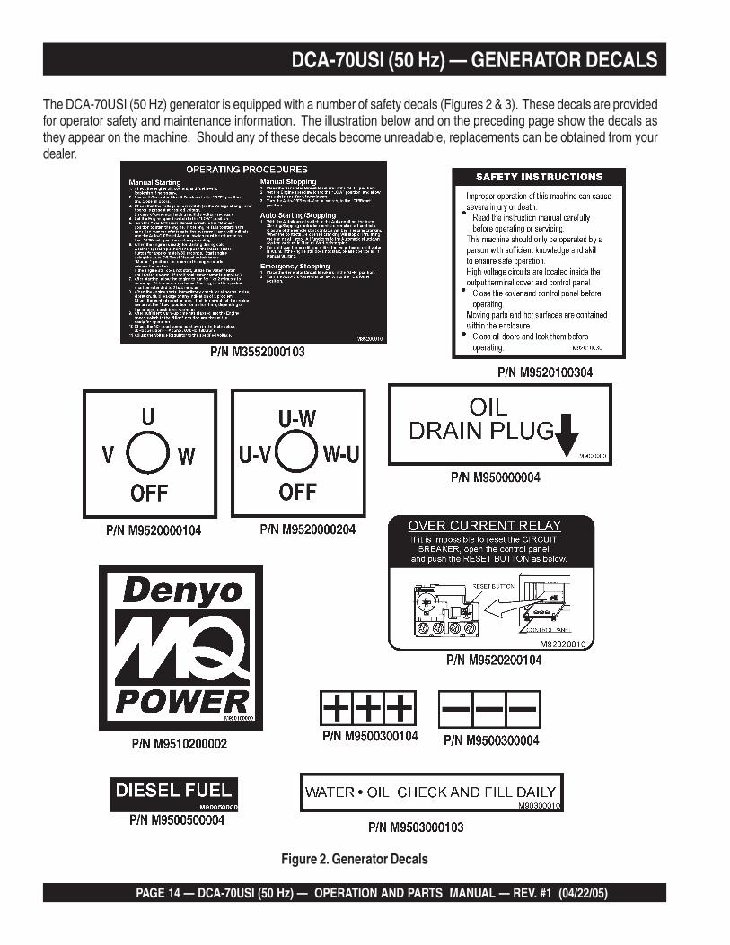
The DCA-70USI (50 Hz) generator is equipped with a number of safety decals (Figures 2 & 3). These decals are providedfor operator safety and maintenance information. The illustration below and on the preceding page show the decals asthey appear on the machine. Should any of these decals become unreadable, replacements can be obtained from yourdealer.
DCA-70USI (50 Hz) — GENERATOR DECALS
Figure 2. Generator Decals

DCA-70USI (50 Hz) — OPERATION AND PARTS MANUAL — REV. #1 (04/22/05) — PAGE 15
1
DCA-70USI (50 Hz) — GENERATOR DECALS
Figure 3. Generator Decals (Cont inued)

PAGE 16 — DCA-70USI (50 Hz) — OPERATION AND PARTS MANUAL — REV. #1 (04/22/05)
Figure 4. Typical Generator Grounding Application
DCA-70USI (50 Hz) — INSTALLATION

DCA-70USI (50 Hz) — OPERATION AND PARTS MANUAL — REV. #1 (04/22/05) — PAGE 17
1
Outdoor Installation
Install the generator in a area that is free of debris,bystanders, and overhead obstructions. Make sure thegenerator is on secure level ground so that it cannot slide orshift around. Also install the generator in a manner so thatthe exhaust will not be discharged in the direction of nearbyhomes.
The installation site must be relatively free from moistureand dust. All electrical equipment should be protected fromexcessive moisture. Failure to do will result in deteriorationof the insulation and will result in short circuits and grounding.
Foreign materials such as dust, sand, lint and abrasivematerials have a tendency to cause excessive wear toengine and alternator parts.
Generator Grounding
To guard against electrical shock and possible damage tothe equipment, it is important to provide a good EARTHground.
Article 250 (Grounding) of the National Electrical Code (NEC)provides guide lines for proper grounding and specifies thatthe cable ground shall be connected to the grounding systemof the building as close to the point of cable entry aspractical.
NEC articles 250-64(b) and 250-66 set the followinggrounding requirements:
1. Use one of the following wire types to connect thegenerator to earth ground.
a. Copper - 10 AWG (5.3 mm2) or larger.
b. Aluminum - 8 AWG (8.4 mm2) or larger.
2. When grounding the generator (Figure 4) connect theground cable between the lock washer and the nut onthe generator and tighten the nut fully. Connect the otherend of the ground cable to earth ground.
3. NEC article 250-52(c) specifies that the earth groundrod should be buried aminimum of 8 ft. into the ground.
When connecting the generatorto any buildings electricalsystem ALWAYS consult witha licensed electrician.
DCA-70USI (50 Hz) — INSTALLATION
NOTE
Indoor Installation
Exhaust gases from diesel engines are extremely poisonous.Whenever an engine is installed indoors the exhaust fumesmust be vented to the outside. The engine should be installedat least two feet from any outside wall. Using an exhaustpipe which is too long or too small can cause excessiveback pressure which will cause the engine to heat excessivelyand possibly burn the valves.
Mounting
The generator must be mounted on a solid foundation (suchas concrete) and set firmly on the foundation to isolatevibration of the generator when it is running. The generatormust set at least 6 inches above the floor or grade level (inaccordance to NFPA 110, Chapter 5-4.1). DO NOT removethe metal skids on the bottom of the generator. They are toresist damage to the bottom of the generator and to maintainalignment.
Pay close attention to ventilation when operating thegenerator inside tunnels and caves. The engine exhaustcontains noxious elements. Engine exhaust must be routedto a ventilated area.
CAUTION - EXHAUST HAZARD

PAGE 18 — DCA-70USI (50 Hz) — OPERATION AND PARTS MANUAL — REV. #1 (04/22/05)
DCA-70USI (50 Hz) — GENERAL INFORMATION
DCA-70USI Ultra Silent™ (50 Hz) Series FamiliarizationGeneratorThe MQ Power Model DCA-70USI (50 Hz) is a 48 kWgenerator (Figure 5) that is designed as a high qualityportable (requires a trailer for transport) power source fortelecom sites, lighting facilities, power tools, submersiblepumps and other industrial and construction machinery.Engine Operating PanelThe “Engine Operating Panel” is provided with the following:
■■■■■ Tachometer■■■■■ Water Temperature Gauge■■■■■ Oil Pressure Gauge■■■■■ Charging Ammeter Gauge■■■■■ Fuel Level Gauge■■■■■ Pre-Heat Pushbutton■■■■■ Pre-Heat Lamp■■■■■ Panel Light/Panel Light Switch■■■■■ Auto ON/OFF Engine Controller (MPEC)■■■■■ Fuel Leak Detected Alarm Lamp
Generator Control PanelThe “Generator Control Panel” is provided with the following:
■■■■■ Frequency Meter (Hz)■■■■■ AC Ammeter (Amps)■■■■■ AC Voltmeter (Volts)■■■■■ Ammeter Change-Over Switch■■■■■ Voltmeter Change-Over Switch■■■■■ Voltage Regulator■■■■■ 3-Pole, 175 amp Main Circuit Breaker■■■■■ “Control Box” (located behind the Gen. Control Panel)
■■■■■ Automatic Voltage Regulator■■■■■ Current Transformer■■■■■ Over-Current Relay■■■■■ Voltage Rectifer■■■■■ Starter Relay■■■■■ Engine Controller (Computer Controlled)■■■■■ Voltage Selector Switch
Output Terminal PanelThe “Output Terminal Panel” is provided with the following:
■■■■■ Three 100/200V output receptacles (CS-6369), 50A■■■■■ Three auxilliary circuit breakers, 50A■■■■■ Two 100V output receptacles (GFCI), 20A■■■■■ Two GFCI circuit breakers, 20A■■■■■ Five output terminal lugs (3Ø power)■■■■■ Battery Charger (Optional)■■■■■ Water Heater (Optional)
Open Delta Excitation SystemThe DCA-70USI (50 Hz) generator is equipped with the stateof the art "Open-Delta" excitation system. The open deltasystem consist of an electrically independent winding woundamong stationary windings of the AC output section.There are four connections of the open delta A, B, C and D.During steady state loads, the power from the voltage regulatoris supplied from the parallel connections of A to B, A to D,and C to D. These three phases of the voltage input to thevoltage regulator are then rectified and are the excitationcurrent for the exciter section.When a heavy load, such as a motor starting or a shortcircuit occurs, the automatic voltage regulator (AVR)switches the configuration of the open delta to the seriesconnection of B to C. This has the effect of adding the voltagesof each phase to provide higher excitation to the excitersection and thus better voltage response during theapplication of heavy loads.The connections of the AVR to the AC output windings arefor sensing only. No power is required from these windings.The open-delta design provides virtually unlimited excitationcurrent, offering maximum motor starting capabilities. Theexcitation does not have a "fixed ceiling" and respondsaccording the demands of the required load.EngineThe DCA-70USI (50 Hz) is powered by a 4 cycle, watercooled, direct injection, turbocharged ISUZU Model FF-4BG1T Diesel Engine. This engine is designed to meet everyperformance requirement for the generator. Reference Table1 for engine specifications.In keeping with MQ Power's policy of constantly improvingits products, the specifications quoted herein are subject tochange without prior notice.Electric Governor SystemThe electric governor system controls the RPMs of theengine. When the engine demand increases or decreases,the governor system regulates the frequency variation to±.25%.Extension CablesWhen electric power is to be provided to various tools orloads at some distance from the generator, extension cordsare normally used. Cables should be sized to allow fordistance in length and amperage so that the voltage dropbetween the generator and point of use (load) is held to aminimum. Use the cable selection chart (Table 6) as a guidefor selecting proper extension cable size.

DCA-70USI (50 Hz) — OPERATION AND PARTS MANUAL — REV. #1 (04/22/05) — PAGE 19
1
DCA-70USI (50 Hz) — MAJOR COMPONENTS
Figure 5. Major Components
4elbaT . stnenopmoCrojaMrotareneG
.ONMETI NOITPIRCSED
1 ylbmessArelffuM
2 ylbmessAenignE
3 ylbmessAerusolcnE
4 ylbmessArotareneG
5 ylbmessAlanimreTtuptuO
6 ylbmessAknaTleuF
7 ylbmessAyrettaB
8 ylbmessAlenaPlortnoCrotareneG
9 ylbmessAlenaPgnitarepOenignE

PAGE 20 — DCA-70USI (50 Hz) — OPERATION AND PARTS MANUAL — REV. #1 (04/22/05)
NOTE PAGE

DCA-70USI (50 Hz) — OPERATION AND PARTS MANUAL — REV. #1 (04/22/05) — PAGE 21
1
DCA-70USI (50 Hz) — GENERATOR CONTROL PANEL
The definitions below describe the controls and functions ofthe DCA-70USI (50 Hz) Generator Control Panel (Figure6).
1. Main Circuit Breaker – This three-pole, 175A mainbreaker is provided to protect the the U,V, and W OutputTerminal Lugs from overload.
2. Frequency Meter – Indicates the output frequency inhertz (Hz). Normally 50 Hz.
3. AC Ammeter – Indicates the amount of current the loadis drawing from the generator per leg selected by theammeter phase-selector switch.
4. Ammeter Change-Over Switch – This switch allowsthe AC ammeter to indicate the current flowing to theload connected to any phase of the output terminals, orto be switched off. This switch does not effect thegenerator output in any fashion, it is for current readingonly.
5. AC Voltmeter – Indicates the output voltage present atthe U,V, and W Output Terminal Lugs.
6. Voltmeter Change-Over Switch – This switch allowsthe AC voltmeter to indicate phase to phase voltagebetween any two phases of the output terminals or tobe switched off.
7. Voltage Regulator Control – Allows ±15% manualadjustment of the generator’s output voltage.
Located behind the generator control panel is the GeneratorControl Box. This box contains some of the necessaryelectronic components required to make the generatorfunction.
The Control Box is equipped with the following majorcomponents:■■■■■ Over-Current Relay■■■■■ Voltage Rectifer (AVR)■■■■■ Starter Relay■■■■■ Current Transformer■■■■■ Voltage Selector Switch■■■■■ Three Phase Circuit Breaker
Figure 6. Generator Control Panel
Remember the overcurrentrelay monitors the currentflowing from the U,V, and WOutput Terminal Lugs to theload.
In the event of a short circuit or over current condition, it willautomatically trip the 60 amp main breaker.
To restore power to the Output Terminal Panel, press thereset button on the overcurrent relay and place the maincircuit breaker in the closed position (ON).
NOTE

PAGE 22 — DCA-70USI (50 Hz) — OPERATION AND PARTS MANUAL — REV. #1 (04/22/05)
Figure 7. Engine Operating Panel
DCA-70USI (50 Hz) — ENGINE OPERATING PANEL

DCA-70USI (50 Hz) — OPERATION AND PARTS MANUAL — REV. #1 (04/22/05) — PAGE 23
1
DCA-70USI (50 Hz) — ENGINE OPERATING PANEL
The definitions below describe the controls and functions ofthe DCA-70USI (50 Hz) Engine Operating Panel (Figure 7).1. Panel Light – Normally used in dark areas or at night
time. When activated, panel lights will illuminate. Whenthe generator is not in use be sure to turn the panellight switch to the OFF position.
2. Panel Light Switch – When activated will turn on controlpanel light.
3. Oil Pressure Gauge – During normal operation thisgauge be should read between 28 to 71 psi. (193~490kPa). When starting the generator the oil pressure mayread a little higher, but after the engine warms up the oilpressure should return to the correct pressure range.
4. Water Temperature Gauge – During normal operationthis gauge be should read between 165° and 203°F.
5. Charging Ammeter Gauge – Indicates the currentbeing supplied by the engine’s alternator which providescurrent for generator’s control circuits and batterycharging system.
6. Fuel Gauge - Indicates amount of diesel fuel available.7. Tachometer – Indicates engine speed in RPM’s for 50
Hz operation. This meter should indicate 1500 RPM’swhen the rated load is applied. In addition a built in hourmeter will record the number of operational hours thatthe generator has been in use.
8. Fuel Leak Detected Alarm Lamp – This lamp willilluminate when a leak in the fuel tank containmentenclosure is detected.
9. Pre-Heat Button – Press and hold this button for 5seconds to warm (cold weather) the engine glow plugs.While holding button down, verify that pre-heat lamp ison.
10. Pre-Heat Lamp – As the engine cranks, this lamp willilluminate to indicate automatic preheating of the engine.When the lamp turns off, the engine has been preheatedand will start automatically.
A. MPEC Control Switch – This switch controls therunning of the unit. If this switch is set to theOFF/RESET position, the unit will not run. When thisswitch is set to the MANUAL position, the generatorwill start immediately.
If the generator is to be connected to a building's ACpower source via a transfer switch (isolation), placethe switch in the AUTO position. In this position thegenerator will monitor the AC line output from thebuilding's power source.
B. Low Oil Pressure – Indicates the engine pressure hasfallen below 15 psi. The oil pressure is detected usingvariable resistive values from the oil pressure sendingunit. This is considered a major fault.
C. High Coolant Temperature – Indicates the enginetemperature has exceeded 239°F. The enginetemperature is detected using variable resistive valuesfrom the temperature sending unit. This is considereda major fault.
D. Overcrank Shutdown – Indicates the unit hasattempted to start a pre- programmed number of times,and has failed to start. The number of cycles andduration are programmable. It is pre-set at 3 cycleswith a 10 second duration. This is considered a majorfault.
E. Overspeed Shutdown – Indicates the engine is runningat an unsafe speed. This is considered a major fault.
F. Engine Running – Indicates that engine is running ata safe operating speed.
During cranking cycle , The MPEC will attempt to crank theengine for 10 seconds before disengaging. If the engine doesnot engage (start) by the third attempt, the engine will beshutdown by the engine controller’s Over Crank Protectionmode. If the engine engages at a speed (RPM's) that is notsafe, the controller will shutdown the engine by initializingthe Over Speed Protection mode.
Also the engine controller will shut down the engine in theevent of low oil pressure, high coolant temperature, lowcoolant level, and loss of magnetic pickup. These conditionscan be observed by monitoring the LED status indicators onthe front of the controller module.
11. Auto On/Off Engine Controller(MPEC) –This controller has a vertical rowof status LED's (inset), thatwhen lit, indicate that an enginemalfunction (fault) has beendetected. When a fault has beendetected the engine controllerwill evaluate the fault and allmajor faults will shutdown the generator.

PAGE 24 — DCA-70USI (50 Hz) — OPERATION AND PARTS MANUAL — REV. #1 (04/22/05)
Output Terminal Familiarization
The “Output Terminal Panel ” (Figure 8) is provided with thefollowing:
■■■■■ Three (3) 100/200V output receptacles @ 50 amp
■■■■■ Three (3) Circuit Breakers @ 50 amps
■■■■■ Two (2) 100V GFCI receptacles @ 20 amp
■■■■■ Two (2) GFCI Circuit Breakers @ 20 amps
■■■■■ Five (5) Output Terminal Lugs ( U, V, W, O, Ground)
Output Terminal Panel
The Output Terminal Panel (Figure 8) shown below is locatedon the right-hand side (left from control panel) of the generator.Lift up on the cover to gain access to receptacles and terminallugs.
NOTE Terminal legs “O” and “Ground”are considered bonded grounds.
Figure 8. Output Terminal Panel
DCA-70USI (50 Hz) — OUTPUT TERMINAL PANEL FAMILIARIZATION

DCA-70USI (50 Hz) — OPERATION AND PARTS MANUAL — REV. #1 (04/22/05) — PAGE 25
1
100 VAC GFCI ReceptaclesThere are two 100 VAC, 20 amp GFCI (Duplex Nema 5-20R)recepacles provided on the output terminal panel. Thesereceptacles can be accessed in any voltage selector switchposition. Each receptacle is protected by a 20 amp circuitbreaker. These breakers are located directly above the GFCIreceptacles. Remember the load output (current) of bothGFCI receptacles is dependent on the load requirements ofthe U, V, and W output terminal lugs.
Pressing the reset button resets the GFCI receptacle afterbeing tripped. Pressing the Test Button (See Figure 9) inthe center of the receptacle will check the GFCI function.Both receptacles should be tested at least once a month.
Figure 9. G.F.C.I. Receptacle
Each auxilliary receptacle is protected by a 50 amp circuitbreaker. These breakers are located directly above the GFCIreceptacles. Remember the load output (current) on all threereceptacles is dependent on the load requirements of theOutput Terminal Lugs.
Turn the voltage regulator control knob (Figure 11) on thecontrol panel to obtain the desired voltage. Turning the knobclockwise will increase the voltage, turning the knob counter-clockwise will decrease the voltage.
Figure 10. 100/100V Twist-LockAuxiliary Receptacles
DCA-70USI (50 Hz) — OUTPUT TERMINAL PANEL FAMILIARIZATION
Twist Lock Dual Voltage 100/200 VAC Receptacles
There are three 100/200V, 50 amp auxilliary twist-lock(CS-6369) recepacles (Figure 10) provided on the outputterminal panel.These receptacles can only be accessedwhen the voltage selector switch is placed in the single-phase 200/100 position.
Figure 11. Voltage Regulator Control Knob
Figure 12. Plastic Face Plate (Output Terminal Lugs)
Removing the Plastic Face Plate (Hard Wire Hookup Panel)
The Output Terminal Lugs are protected by a plastic faceplate cover (Figure 12). Un-screw the securing bolts and liftthe plastic terminal cover to gain access to the terminalenclosure.
After the load wires have been securely attached to theterminal lugs, reinstall the plastic face plate.

PAGE 26 — DCA-70USI (50 Hz) — OPERATION AND PARTS MANUAL — REV. #1 (04/22/05)
Figure 13. Connecting Loads
Connecting Loads
Loads can be connected to the generator by the OuputTerminal Lugs or the convienience receptacles (Figure 13).Make sure to read the operation manual before attemptingto connect a load to the generator.
To protect the output terminals from overload, a3-pole, 175A main circuit breaker is provided. Make sure toswitch ALL circuit breakers to the OFF position prior tostarting the engine.
DCA-70USI (50 Hz) — OUTPUT TERMINAL PANEL FAMILIARIZATION
Over Current RelayAn over current relay (Figure 14) is connected to the maincircuit breaker. In the event of an overload, both the circuitbreaker and the over current relay may trip. If the circuitbreaker can not be reset, the reset button on the over cur-rent relay must be pressed. The over current relay is lo-cated in the control box.
Figure 14. Over Current Relay
Blower Fan
This unit has an intake fan located at the rear of the machineto draw outside air into the cabinet to cool the engine. Thefan has a 10 amp AC fuse located beneath the VoltageSelector Switch (Figure 15).
Figure 15. Blower Fan Fuse
This fuse has current running through it any time the engineis running. This fuse is NOT connected to the main circuitbreaker of the generator. Attempting to replace the fusewith the engine and/or generator operatingcould result in electrocution and severebodily harm. ALWAYS turn the unitcompletely off before attempting to replaceor handle this fuse.
DANGER - ELECTROCUTION HAZARDS
DCA-70USI (50 Hz) — OPERATION AND PARTS MANUAL — REV. #1 (04/22/05) — PAGE 27
1
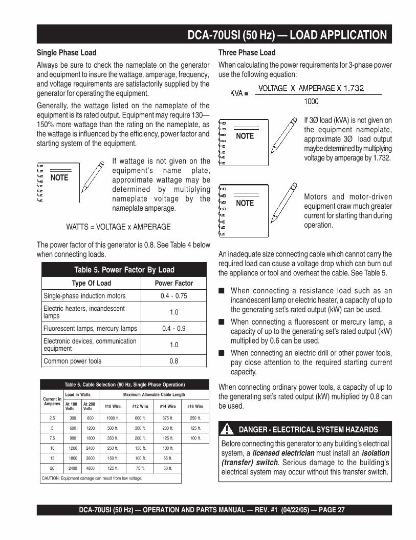
DCA-70USI (50 Hz) — LOAD APPLICATIONSingle Phase Load
Always be sure to check the nameplate on the generatorand equipment to insure the wattage, amperage, frequency,and voltage requirements are satisfactorily supplied by thegenerator for operating the equipment.
Generally, the wattage listed on the nameplate of theequipment is its rated output. Equipment may require 130—150% more wattage than the rating on the nameplate, asthe wattage is influenced by the efficiency, power factor andstarting system of the equipment.
Motors and motor-drivenequipment draw much greatercurrent for starting than duringoperation.
When connecting ordinary power tools, a capacity of up tothe generating set’s rated output (kW) multiplied by 0.8 canbe used.
If wattage is not given on theequipment's name plate,approximate wattage may bedetermined by multiplyingnameplate voltage by thenameplate amperage.
The power factor of this generator is 0.8. See Table 4 belowwhen connecting loads.
If 3Ø load (kVA) is not given onthe equipment nameplate,approximate 3Ø load outputmaybe determined by multiplyingvoltage by amperage by 1.732.
■■■■■ When connecting a resistance load such as anincandescent lamp or electric heater, a capacity of up tothe generating set’s rated output (kW) can be used.
■■■■■ When connecting a fluorescent or mercury lamp, acapacity of up to the generating set’s rated output (kW)multiplied by 0.6 can be used.
■■■■■ When connecting an electric drill or other power tools,pay close attention to the required starting currentcapacity.
NOTE
WATTS = VOLTAGE x AMPERAGE
Three Phase Load
When calculating the power requirements for 3-phase poweruse the following equation:
NOTE
An inadequate size connecting cable which cannot carry therequired load can cause a voltage drop which can burn outthe appliance or tool and overheat the cable. See Table 5.
NOTE
Before connecting this generator to any building’s electricalsystem, a licensed electrician must install an isolation(transfer) switch. Serious damage to the building’selectrical system may occur without this transfer switch.
DANGER - ELECTRICAL SYSTEM HAZARDS
daoLyBrotcaFrewoP.5elbaT
daoLfOepyT rotcaFrewoP
srotomnoitcudniesahp-elgniS 57.0-4.0
tnecsednacni,sretaehcirtcelEspmal 0.1
spmalyrucrem,spmaltnecseroulF 9.0-4.0
noitacinummoc,secivedcinortcelEtnempiuqe 0.1
slootrewopnommoC 8.0
)noitarepOesahPelgniS,zH06(noitceleSelbaC.6elbaT
nitnerruCserepmA
sttaWnIdaoL htgneLelbaCelbawollAmumixaM
001tAstloV
002tAstloV eriW01# eriW21# eriW41# eriW61#
5.2 003 006 .tf0001 .tf006 .tf573 .tf052
5 006 0021 .tf005 .tf003 .tf002 .tf521
5.7 009 0081 .tf053 .tf002 .tf521 .tf001
01 0021 0042 .tf052 .tf051 .tf001
51 0081 0063 .tf051 .tf001 .tf56
02 0042 0084 .tf521 .tf57 .tf05
.egatlovwolmorftlusernacegamadtnempiuqE:NOITUAC
PAGE 28 — DCA-70USI (50 Hz) — OPERATION AND PARTS MANUAL — REV. #1 (04/22/05)
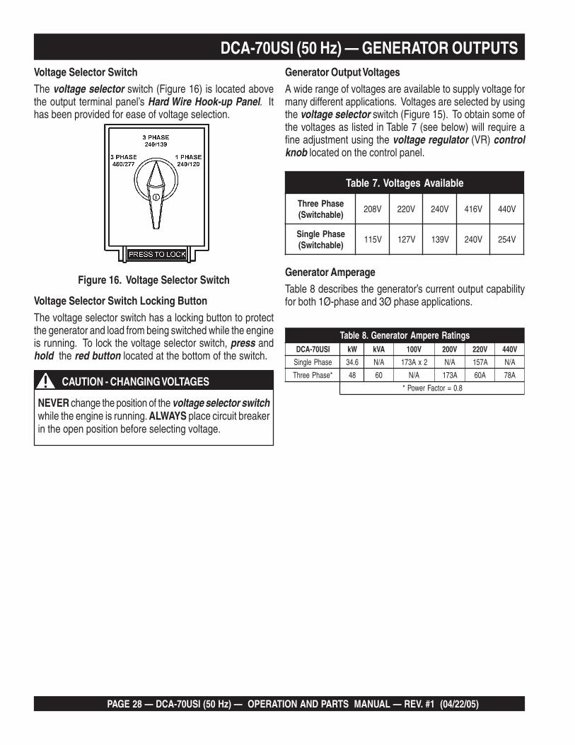
Voltage Selector SwitchThe voltage selector switch (Figure 16) is located abovethe output terminal panel’s Hard Wire Hook-up Panel. Ithas been provided for ease of voltage selection.
Voltage Selector Switch Locking ButtonThe voltage selector switch has a locking button to protectthe generator and load from being switched while the engineis running. To lock the voltage selector switch, press andhold the red button located at the bottom of the switch.
Figure 16. Voltage Selector Switch
DCA-70USI (50 Hz) — GENERATOR OUTPUTS
Generator AmperageTable 8 describes the generator’s current output capabilityfor both 1Ø-phase and 3Ø phase applications.
Generator Output VoltagesA wide range of voltages are available to supply voltage formany different applications. Voltages are selected by usingthe voltage selector switch (Figure 15). To obtain some ofthe voltages as listed in Table 7 (see below) will require afine adjustment using the voltage regulator (VR) controlknob located on the control panel.
NEVER change the position of the voltage selector switchwhile the engine is running. ALWAYS place circuit breakerin the open position before selecting voltage.
CAUTION - CHANGING VOLTAGES
elbaliavAsegatloV.7elbaT
esahPeerhT)elbahctiwS(
V802 V022 V042 V614 V044
esahPelgniS)elbahctiwS(
V511 V721 V931 V042 V452
sgnitaRerepmArotareneG.8elbaTISU07-ACD Wk AVk V001 V002 V022 V044
esahPelgniS 6.43 A/N 2xA371 A/N A751 A/N
*esahPeerhT 84 06 A/N A371 A06 A87
8.0=rotcaFrewoP*
DCA-70USI (50 Hz) — OPERATION AND PARTS MANUAL — REV. #1 (04/22/05) — PAGE 29
1
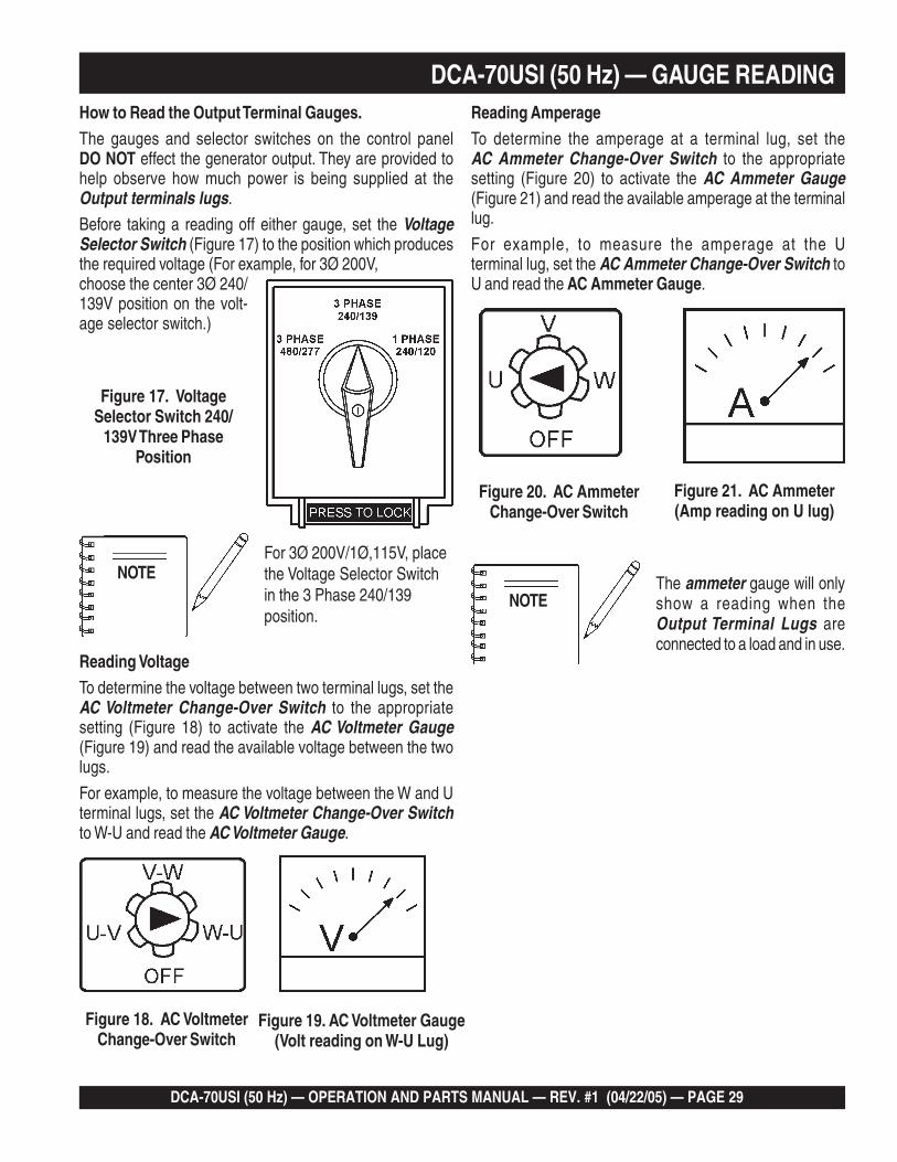
DCA-70USI (50 Hz) — GAUGE READINGHow to Read the Output Terminal Gauges.The gauges and selector switches on the control panelDO NOT effect the generator output. They are provided tohelp observe how much power is being supplied at theOutput terminals lugs.
Before taking a reading off either gauge, set the VoltageSelector Switch (Figure 17) to the position which producesthe required voltage (For example, for 3Ø 200V,choose the center 3Ø 240/139V position on the volt-age selector switch.)
Figure 17. VoltageSelector Switch 240/
139V Three PhasePosition
Figure 18. AC VoltmeterChange-Over Switch
Figure 19. AC Voltmeter Gauge(Volt reading on W-U Lug)
For 3Ø 200V/1Ø,115V, placethe Voltage Selector Switchin the 3 Phase 240/139position.
Figure 21. AC Ammeter(Amp reading on U lug)
Figure 20. AC AmmeterChange-Over Switch
The ammeter gauge will onlyshow a reading when theOutput Terminal Lugs areconnected to a load and in use.
NOTE
Reading VoltageTo determine the voltage between two terminal lugs, set theAC Voltmeter Change-Over Switch to the appropriatesetting (Figure 18) to activate the AC Voltmeter Gauge(Figure 19) and read the available voltage between the twolugs.
For example, to measure the voltage between the W and Uterminal lugs, set the AC Voltmeter Change-Over Switchto W-U and read the AC Voltmeter Gauge.
NOTE
Reading AmperageTo determine the amperage at a terminal lug, set theAC Ammeter Change-Over Switch to the appropriatesetting (Figure 20) to activate the AC Ammeter Gauge(Figure 21) and read the available amperage at the terminallug.
For example, to measure the amperage at the Uterminal lug, set the AC Ammeter Change-Over Switch toU and read the AC Ammeter Gauge.

PAGE 30 — DCA-70USI (50 Hz) — OPERATION AND PARTS MANUAL — REV. #1 (04/22/05)
Figure 22. Voltage Selector Switch 240/139VThree-Phase Position
DCA-70USI (50 Hz) — OUTPUT TERMINAL PANEL CONNECTIONSUVWO Terminal Output VoltagesVarious output voltages can be obtained using the OutputTerminal Lugs. The voltages at the terminals are depen-dent on the position of the Voltage Selector Switch and theadjustment of the Voltage Regulator Control Knob.
Remember the voltage selector switch determines the rangeof the output voltage. The voltage regulator (VR) allows theuser to increase or decrease the selected voltage.
3Ø 220/127 Output Terminal Lug Voltages
1. Place the voltage selector switch in the 3Ø 240/139position as shown in Figure 22.
Figure 23. Output Terminal Lugs3Ø-220/127V Connections
2. Connect the load wires to the Output Terminal Lugs asshown in Figure 22.
3. Turn the voltage regulator knob (Figure 23) clockwise toincrease voltage output, turn counterclockwise todecrease voltage output.
3Ø 200V/1Ø115V Output Terminal Lug Voltages
1. Place the voltage selector switch in the 3Ø 240/139position as shown in Figure 25.
Figure 24. Voltage Regulator Knob (139V/240V)
Use this position for3Ø-200 or 1Ø115V.
2. Connect the load wires to the Output Terminal Lugs asshown in Figure 26.
3. Turn the voltage regulator knob (Figure 24) clockwise toincrease voltage output, turn counterclockwise todecrease voltage output.
NOTE
To achieve a 3Ø 200V outputthe voltage selector switchmust be in the 3Ø-240/139position and the voltageregulator must be adjusted to200V.
Figure 26. Output Terminal Lugs3Ø-200/115V Connections
Figure 25. Voltage SelectorSwitch 240/139V
Three-Phase Position

DCA-70USI (50 Hz) — OPERATION AND PARTS MANUAL — REV. #1 (04/22/05) — PAGE 31
1
Figure 27. Voltage Selector Switch 480/277VThree-Phase Position
3Ø 440/254 Output Terminal Lug Voltages1. Place the voltage selector switch in the 3Ø 480/277
position as shown in Figure 27.
Figure 28. Output Terminal Lugs1Ø-440/254V Connections
2. Connect the load wires to the Output Terminal Lugs asshown in Figure 28.
3. Turn the voltage regulator knob (Figure 24) clockwise toincrease voltage output, turn counterclockwise todecrease voltage output.
1Ø 200V/100V Output Terminal Lug Voltages
1. Place the voltage selector switch in the 1Ø 240/120position as shown in Figure 29.
2. Connect the load wires to the Output Terminal Lugs asshown in Figure 30.
3. Turn the voltage regulator knob (Figure 25) clockwise toincrease voltage output, turn counterclockwise todecrease voltage output.
Figure 30. Output Terminal Lugs1Ø-200/100V Connections
DCA-70USI (50 Hz) — OUTPUT TERMINAL PANEL CONNECTIONS
Figure 29. Voltage Selector Switch 240/120VSingle-Phase Position

PAGE 32 — DCA-70USI (50 Hz) — OPERATION AND PARTS MANUAL — REV. #1 (04/22/05)
DCA-70USI (50 Hz) — PRE-SETUP
Figure 31. Engine Oil Dipstick
When checking the engine oil, be sure to check if the oil isclean. If the oil is not clean, drain the oil by removing the oildrain plug, and refill with the specified amount of oil as outlinedin the ISUZU Engine Owner's Manual. Oil should be warmbefore draining.
Other types of motor oils may be substituted if they meetthe following requirements:
■■■■■ API Service Classification CC/SC■■■■■ API Service Classification CC/SD■■■■■ API Service Classification CC/SE■■■■■ API Service Classification CC/SF
Circuit Breakers
To protect the generator from an overload, a 3-pole, 175 amp,main circuit breaker is provided to protect the U,V, and WOutput Terminals from overload. In addition two single-pole,20 amp GFCI circuit breakers are provided to protect theGFCI receptacles from overload. Three 50 amp load circuitbreakers have also been provided to protect the auxiliaryreceptacles from overload. Make sure to switch ALL circuitbreakers to the OFF position prior to starting the engine.
Lubrication Oil
Fill the engine crankcase with lubricating oil through the fillerhole, but DO NOT overfill. Make sure the generator is level.and verify that the oil level is maintained between the twonotches (Figure 31) on the dipstick. See Table 9 for properselection of engine oil.
Figure 32. Internal Fuel Tank System
Refilling the Fuel System
Fuel Check
This generator has an internal fuel tank located inside thetrailer frame and may also be equipped with an environmentalfuel tank (Figure 32). ALWAYS fill the fuel tanks with cleanfresh #2 diesel fuel. DO NOT fill the fuel tanks beyond theircapacities.
Pay attention to the fuel tank capacity when replenishingfuel.The fuel tank cap must be closed tightly after filling.Handle fuel in a safety container. If the container does nothave a spout, use a funnel. Wipe up any spilled fuelimmediately.
ONLY properly trained personel who have read andunderstand this section should refill the fuel tank system.
CAUTION - REFUELING THE GENERATOR
Fuel spillage on a hot engine can cause a fire or explosion.If fuel spillage occurs, wipe up the spilled fuel completelyto prevent fire hazards. NEVER smoke around or near thegenerator.
DANGER - EXPLOSION/FIRE HAZARDS
DCA-70USI (50 Hz) — OPERATION AND PARTS MANUAL — REV. #1 (04/22/05) — PAGE 33
1
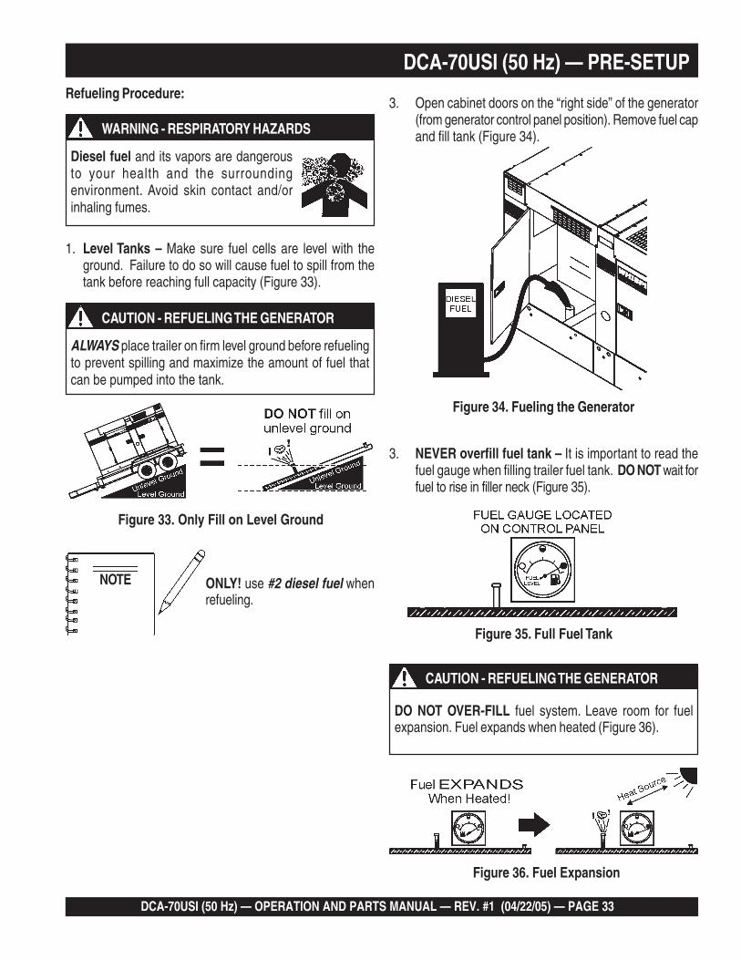
DCA-70USI (50 Hz) — PRE-SETUPRefueling Procedure:
1. Level Tanks – Make sure fuel cells are level with theground. Failure to do so will cause fuel to spill from thetank before reaching full capacity (Figure 33).
Figure 33. Only Fill on Level Ground
ONLY! use #2 diesel fuel whenrefueling.
NOTE
3. NEVER overfill fuel tank – It is important to read thefuel gauge when filling trailer fuel tank. DO NOT wait forfuel to rise in filler neck (Figure 35).
Figure 35. Full Fuel Tank
Figure 36. Fuel Expansion
3. Open cabinet doors on the “right side” of the generator(from generator control panel position). Remove fuel capand fill tank (Figure 34).
Figure 34. Fueling the Generator
ALWAYS place trailer on firm level ground before refuelingto prevent spilling and maximize the amount of fuel thatcan be pumped into the tank.
CAUTION - REFUELING THE GENERATOR
Diesel fuel and its vapors are dangerousto your health and the surroundingenvironment. Avoid skin contact and/orinhaling fumes.
WARNING - RESPIRATORY HAZARDS
DO NOT OVER-FILL fuel system. Leave room for fuelexpansion. Fuel expands when heated (Figure 36).
CAUTION - REFUELING THE GENERATOR

PAGE 34 — DCA-70USI (50 Hz) — OPERATION AND PARTS MANUAL — REV. #1 (04/22/05)
Coolant (ISUZU Antifreeze/Summer Coolant/Water)ISUZU recommends ISUZU Antifreeze/Summer Coolant foruse in thier engines, which can be purchased in concentrate(and mixed with 50% demineralized water) or pre-diluted.See the ISUZU Engine Owner's Manual for further details.
Day-to-day addition of coolant is done from the recoverytank. When adding coolant to the radiator, DO NOT removethe radiator cap until the unit has completely cooled. SeeTable 10 for engine, radiator, and recovery tank coolantcapacities. Make sure the coolant level in the recovery tankis always between the "H" and the "L" markings.
Operation Freezing Weather
When operating in freezing weather, be certain the properamount of antifreeze (Table 11) has been added.
Cleaning the Radiator
The engine may overheat if the radiator fins becomeoverloaded with dust or debris. Periodically clean the radiatorfins with compressed air. Cleaning inside the machine isdangerous, so clean only with the engine turned off and thenegative battery terminal disconnected.
Air Cleaner
Periodic cleaning/replacement is necessary. Inspect it inaccordance with the ISUZU Engine Owner's Manual.
Fan Belt Tension
A slack fan belt may contribute to overheating, or toinsufficient charging of the battery. Inspect the fan belt fordamage and wear and adjust it in accordance with the ISUZUEngine Owner's Manual.
The fan belt tension is proper if the fan belt bends 10 to 15mm (Figure 37) when depressed with the thumb as shownbelow.
Figure 37. Fan Belt Tension
DCA-70USI (50 Hz) — PRE-SETUP
When the antifreeze is mixed withwater, the antifreeze mixing ratiomust be less than 50%.
NOTE
If adding coolant/antifreeze mix to theradiator, DO NOT remove the radiator capuntil the unit has completely cooled. Thepossibility of hot! coolant exists whichcan cause severe burns.
WARNING - BURN HAZARDS
NEVER place hands nearthe belts or fan while thegenerator set is running.
CAUTION - ROTATING PARTS
yticapaCtnalooC.01elbaT
rotaidaRdnaenignE )sretil4.41(.laG8.3
knaTevreseR )sretil9.1(strauQ2
ezeerF-itnA.11elbaTserutarepmeTgnitarepO
%loVezeerF-itnA
tnioPgnizeerF
C° F°
05 73- 43-

DCA-70USI (50 Hz) — OPERATION AND PARTS MANUAL — REV. #1 (04/22/05) — PAGE 35
1
DCA-70USI (50 Hz) — PRE-SETUPWhen connecting battery do the following:
1. NEVER connect the battery cables to the batteryterminals when the MPEC Control Switch is in eitherthe MANUAL position. ALWAYS make sure that the MPECControl Switch is in the OFF/RESET position whenconnecting the battery.
2. Place a small amount of battery terminal treatmentcompound around both battery terminals. This will ensurea good connection and will help prevent corrosion aroundthe battery terminals.
Figure 38. Battery Connections
ALWAYS disconnect the negative terminal FIRST andreconnect negative terminal LAST.
Inadequate battery connections may cause poor startingof the generator, and create other malfunctions.
Alternator
The polarity of the alternator is negative grounding type. Whenan inverted circuit connection takes place, the circuit will bein short circuit instantaneously resulting the alternator failure.
DO NOT put water directly on the alternator. Entry of waterinto the alternator can cause corrision and damage thealternator.
Wiring
Inspect the entire generator for bad or worn electrical wiringor connections. If any wiring or connections are exposed(insulation missing) replace wiring immediately.
Piping and Hose Connection
Inspect all piping, oil hose, and fuel hose connections forwear and tightness. Tighten all hose clamps and check hosesfor leaks.
If any hose (fuel or oil) lines are defective replace themimmediately.
If the battery cable is connectedincorrectly, electrical damage to thegenerator will occur. Pay closeattention to the polarity of thebattery when connecting thebattery.
NOTE
Battery
This unit is of negative ground DO NOT connect in reverse.Always maintain battery fluid level between the specifiedmarks. Battery life will be shortened, if the fluid level are notproperly maintained. Add only distilled water whenreplenishment is necessary.
DO NOT over fill. Check to see whether the battery cablesare loose. Poor contact may result in poor starting ormalfunctions. Always keep the terminals firmly tightened.Coating the terminals with an approved battery terminaltreatment compound. Replace battery with onlyrecommended type battery. The battery type used in thisgenerator is BCI Group 27.
The battery is sufficiently charged if the specific gravity ofthe battery fluid is 1.28 (at 68° F). If the specific gravityshould fall to 1.245 or lower, it indicates that the battery isdead and needs to be recharged or replaced.
Before charging the battery with an external electric source,be sure to disconnect the battery cables.
Battery Cable Installation
ALWAYS be sure the battery cables (Figure 38) are properlyconnected to the battery terminals as shown below. The RedCable is connected to the positive terminal of the battery,and the Black Cable is connected to the negative terminalof the battery.
CAUTION - BATTERY SERVICING SAFETY
CAUTION - BATTERY SERVICING SAFETY
PAGE 36 — DCA-70USI (50 Hz) — OPERATION AND PARTS MANUAL — REV. #1 (04/22/05)
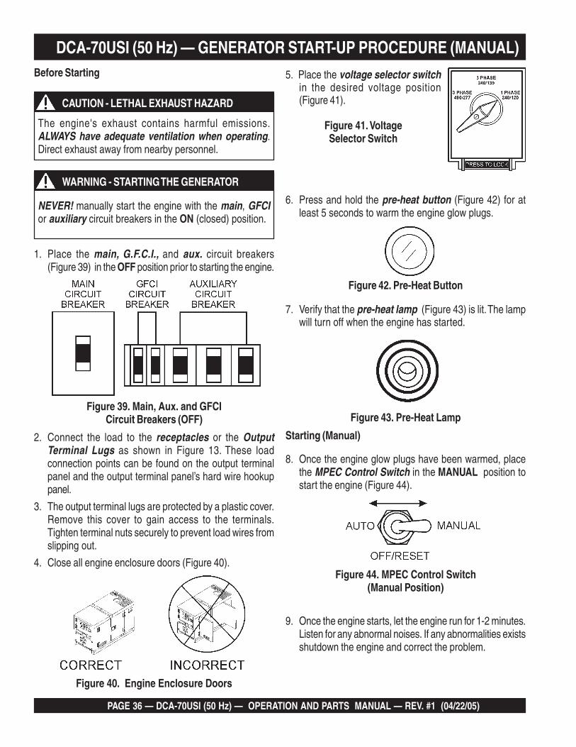
8. Once the engine glow plugs have been warmed, placethe MPEC Control Switch in the MANUAL position tostart the engine (Figure 44).
Starting (Manual)
Figure 44. MPEC Control Switch(Manual Position)
DCA-70USI (50 Hz) — GENERATOR START-UP PROCEDURE (MANUAL)
The engine's exhaust contains harmful emissions.ALWAYS have adequate ventilation when operating.Direct exhaust away from nearby personnel.
Before Starting
Figure 40. Engine Enclosure Doors
1. Place the main, G.F.C.I., and aux. circuit breakers(Figure 39) in the OFF position prior to starting the engine.
2. Connect the load to the receptacles or the OutputTerminal Lugs as shown in Figure 13. These loadconnection points can be found on the output terminalpanel and the output terminal panel’s hard wire hookuppanel.
3. The output terminal lugs are protected by a plastic cover.Remove this cover to gain access to the terminals.Tighten terminal nuts securely to prevent load wires fromslipping out.
4. Close all engine enclosure doors (Figure 40).
Figure 39. Main, Aux. and GFCICircuit Breakers (OFF)
NEVER! manually start the engine with the main, GFCIor auxiliary circuit breakers in the ON (closed) position.
5. Place the voltage selector switchin the desired voltage position(Figure 41).
Figure 41. VoltageSelector Switch
CAUTION - LETHAL EXHAUST HAZARD
WARNING - STARTING THE GENERATOR
6. Press and hold the pre-heat button (Figure 42) for atleast 5 seconds to warm the engine glow plugs.
Figure 42. Pre-Heat Button
7. Verify that the pre-heat lamp (Figure 43) is lit. The lampwill turn off when the engine has started.
9. Once the engine starts, let the engine run for 1-2 minutes.Listen for any abnormal noises. If any abnormalities existsshutdown the engine and correct the problem.
Figure 43. Pre-Heat Lamp

DCA-70USI (50 Hz) — OPERATION AND PARTS MANUAL — REV. #1 (04/22/05) — PAGE 37
1
DCA-70USI (50 Hz) — GENERATOR START-UP PROCEDURE (MANUAL)
Figure 48. Voltage Adjust Control Knob
Figure 49. Ammeter(No Load)
13. The ammeter (Figure 49) willindicate zero amps with no loadapplied. When a load is applied, theammeter will indicate the amount ofcurrent that the load is drawing fromthe generator.
12. The generator's AC-voltmeter (Figure 47) will display thegenerator’s output in VOLTS. If the voltage is not withinthe specified tolerance, use the voltage adjustmentcontrol knob (Figure 48) to increase or decrease thedesired voltage.
Figure 47. Voltmeter
Figure 46. Frequency Meter (Hz)
11. The generator's frequency meter (Figure 46) should bedisplaying the 50 cycle output frequency in HERTZ.
10.Verify that the Engine Runningstatus LED on the MPEC unit(Figure 45) is ON (lit) after theengine has been started.
Figure 45. EngineRunning LED (ON)
Figure 52. EngineTachometer Gauge
16. The tachometer gauge (Figure52) will indicate the speed of theengine when the generator isoperating. Under normal operatingconditions this speed isapproximately 1500 RPM’s.
15. The coolant temperature gauge(Figure 51) will indicate thecoolant temperature. Undernormal operating conditions thecoolant temperature should bebetween 165 and 215 degreesFahrenheit (Green Zone).
Figure 51. CoolantTemperature Gauge
14. The engine oil pressure gauge(Figure 50) will indicate the oilpressure (kg/ cm2) of the engine.Under normal operating conditionsthe oil pressure is approximately35~65 PSI.
Figure 50. OilPressure Gauge
Figure 53. Main, Aux. and GFCICircuit Breakers (ON)
17. Place the main, GFCI, and aux. circuit breakers in theON position (Figure 53).
18. Observe the generator's ammeter(Figure 54) and verify it reads theanticipated amount of current withrespect to the load. The ammeterwill only display a current reading ifa load is in use.
Figure 54. Ammeter(Load)

PAGE 38 — DCA-70USI (50 Hz) — OPERATION AND PARTS MANUAL — REV. #1 (04/22/05)
Shutdown Procedure
To shutdown the generator use the following procedure:
1. Place both the MAIN, GFCI and LOAD circuit breakersas shown in Figure 39 to the OFF position.
3. Let the engine cool by running it for 3-5 minutes with noload applied.
4. Place the MPEC Control Switch (Figure 56) to theOFF/RESET position.
Figure 56. MPEC Control Switch (Off/Reset)
5. Verify that the all status LED on the MPEC displayare OFF (not lit).
6. Remove all loads from the generator.
Emergency Shutdown Procedure
1. To shut-down the engine in the event of an emergency,switch the MAIN, GFCI and LOAD (Figure 39) circuitbreakers to OFF position.
2. Place the MPEC Control Switch switch (Figure 56) tothe OFF/RESET position.
NEVER stop the engine suddenly except in an emergency.DO NOT use the emergency stop switch a as method ofshutting down the generator. This switch is ONLY to beused in the event of an emergency.
WARNING - SHUTTING DOWN THE GENERATOR
1. Perform steps 1 through 5 in the Before Starting sectionas outlined in the Manual Starting Procedure.
2. Place the MPEC Control Switch (Figure 54) in the AUTOposition .
3. Continue to follow the steps outlined in the Manual Start-up procedure (start at step 9).
Figure 55. MPEC Control Switch (AUTO)
When the generator is set in theAUTO mode, the generator willautomically start in the event ofcomercial power falling below aprescribed level by means of acontact closure that is generatedautomatically by a transfer switch.
NOTE
Starting (Auto Mode)
Before connecting this generator to anybuilding’s electrical system, a licensedelectrician must install an isolation(transfer) switch. Serious damage to thebuilding’s electrical system may occurwithout this transfer switch.
DANGER - ELECTRICAL SYSTEM HAZARDS
When connecting the generator to a isolation (transfer)switch, ALWAYS have power applied to the generator'sinternal battery charger. This will ensure that the enginewill not fail due to a dead battery.
CAUTION - BACKUP GENERATOR USE
When running the generator in the AUTO mode, rememberthe generator can start up at any time without warning.NEVER attempt to perform any maintenance when thegenerator is in the auto mode.
WARNING - AUTO MODE MAINTENANCE
19. The generator will run until manually stopped or anabnormal condition occurs.
DCA-70USI (50 Hz) — GENERATOR START-UP PROCEDURE (AUTO MODE)When the MPEC Control Switchis placed in the AUTO position,the engine glow plugs will bewarmed and the engine will startautomatically. The pre-heat lampwill turn off when the engine hasstarted.
NOTE

DCA-70USI (50 Hz) — OPERATION AND PARTS MANUAL — REV. #1 (04/22/05) — PAGE 39
1
DCA-70USI (50 Hz) — MAINTENANCE
Service Daily
If the engine is operating in very dusty or dry grassconditions, a clogged air cleaner will result. This can lead toa loss of power, excessive carbon buildup in the combustionchamber and high fuel consumption. Change air cleanermore frequently if these conditions exists.
Fuel Addition
Add diesel fuel (the grade may vary according to seasonand locations).
Removing Water from the Fuel Tank
After prolonged use, water and other impurities accumulatein the bottom of the tank. Occasionally inspect the fueltank for water contamination and drain the contents ifrequired.
During cold weather, the more empty volume inside thetank, the easier it is for water to condense. This can bereduced by keeping the tank full with diesel fuel.
General Inspection
Prior to each use, the generator should be cleaned andinspected for deficiencies. Check for loose, missing ordamaged nuts, bolts or other fasteners. Also check for fuel,oil, and coolant leaks. Use Table 12 as a general maintenanceguideline Engine Side (Refer to the Engine InstructionManual)
Air Cleaner
Every 250 hours: Remove air cleaner element and clean theheavy duty paper element with light spray of compressedair. Replace the air cleaner as needed.
Air Cleaner with Dust Indicator
This indicator is attached to the air cleaner. When the aircleaner element is clogged, air intake restriction becomesgreater and the dust indicator signal shows RED meaningthe element needs changing or service. After changing theair element, press the dust indicator button to reset theindicator.
ECNANETNIAM/NOITCEPSNI.21ELBAT srH01YLIAD srH052 srH005 srH0001
ENIGNE
sleveLdiulFenignEkcehC X
renaelCriAkcehC X
leveLdicAyrettaBkcehC X
noitidnoCtleBnaFkcehC X
skaeLrofkcehC X
straPfogninesooLrofkcehC X
*retliFdnaliOenignEecalpeR 1 X
retliFriAnaelC X
lwoBrotarepeSretaW/retliFleuFkcehC X
edistuOdnaedisnI,tinUnaelC X
retliFleuFegnahC X
*leveLnoitcetorPtnalooCkcehCdnarotaidaRnaelC 2 X
*tnemelEretliFriAecalpeR 3 X
*spmalCdnasesoHllakcehC 4 X
knaTleuFfoedisnInaelC X
ROTARENEGsmhoM3revOecnatsiseRnoitalusnIerusaeM X
gniraeBtroppuSraeRrotoRkcehC X
.ylnoemittsrif,sruoh001taretliffnalioenigneecalpeR1*
.tnaloocenigneehtegrahcerot")S'ACS(sevitaddAtnalooClatnemelppuS"ddA2*
H.ni52(mm526fomuccavaswohsrotacidninoitcirtsernehwtnemeleretlifriayramirpecalpeR3* 2 .)0
htiw,toofrephcni2/1atsaeltasiesohybolbehtfoepolsehttahterusne,decalperebotsdeenesohybwolbfI4*.lioro/dnaerutsiomtcellocdluoctahtspidrosgason

PAGE 40 — DCA-70USI (50 Hz) — OPERATION AND PARTS MANUAL — REV. #1 (04/22/05)
DCA-70USI (50 Hz) — MAINTENANCE
Generator Storage
For longe term storage of the generator the following isrecommended:
Fill the fuel tank completely. Treat with a fuel stabilizerif necessary.
Completely drain the oil from the crankcase and refill ifnecessary with fresh oil.
Clean the entire generator, internal and external.
Cover the generating set and store in a clean, dry place.
Disconnect the battery.
Make sure engine coolant is at proper level.
If generator is mounted on a trailer, jack trailer up andplace on blocks so tires do not touch the ground or blockand completely remove the tires.
Flushing Out Radiator and Replacing Coolant
Open both cocks located at the crankcase side and atthe lower part of the radiator and drain coolant. Open theradiator cap while draining. Remove the overflow tankand drain.
Check hoses for softening and kinks. Check clamps forsigns of leakage.
Flush the radiator by running clean tap water throughradiator until signs of rust and dirt are removed. DO NOTclean radiator core with any objects, such as ascrewdriver.
Tighten both cocks and replace the overflow tank.
Replace with coolant as recommended by the enginemanufaturer.
Close radiator cap tightly.
Air Removal
If air enters the fuel injection system of a diesel engine,starting becomes impossible. After running out of fuel, orafter disassembling the fuel system, bleed the systemaccording to the following procedure. See the ISUZU EngineManual for details.
To restart after running out of fuel, turn the switch to the“ON” position for 15-30 seconds. Try again, if needed. Thisunit is equipped with an automatic air bleeding system.
Check Oil Level
Check the crankcase oil level prior to each use, or when thefuel tank is filled. Insufficient oil may cause severe damageto the engine. Make sure the generator is level. The oil levelmust be between the two notches on the dipstick as shownin Figure 31.
Replacing Oil Filter
Remove the old oil filter.
Apply a film of oil to the gasket on the new oil filter.
Install the new oil filter.
After the oil cartridge has been replaced, the engine oilwill drop slightly. Run the engine for a while and checkfor leaks before adding more oil if needed. Cleanexcessive oil from engine.
Allow engine to cool when flushing outradiator. Flushing the radiator while hotcould cause serious burns from water orsteam.
WARNING - BURN HAZARDS
Replacing Fuel Filter
Replace the fuel filter cartridge with new one every 500hours or so.
Loosen the drain plug at the lower top of the fuel filter.Drain the fuel in the fuel body together with the mixedwater. DO NOT spill the fuel during disassembly.
Vent any air.
Cleaning the Fuel StrainerClean the fuel strainer if it contains dust or water. Removedust or water in the strainer cap and wash it in gasoline.Securely fasten the fuel strainer cap so that fuel will notleak. Check the fuel strainer every 200 hours of operation oronce a month.

DCA-70USI (50 Hz) — OPERATION AND PARTS MANUAL — REV. #1 (04/22/05) — PAGE 41
1
DCA-70USI (50 Hz) — TRAILER MAINTENANCE7. Coupler - Type of hitch used on the trailer for towing.
8. Tire Size - Indicates the diameter of the tire in inches(10,12,14, etc.), and the width in millimeters(175,185,205, etc.). The tire diameter must match thediameter of the tire rim.
9. Tire Ply - The tire ply (layers) number is rated in letters;2-ply,4-ply,6-ply, etc.
10. Wheel Hub - The wheel hub is connected to the trailer’saxle.
11. Tire Rim - Tires mounted on a tire rim. The tire rim mustmatch the size of the tire.
12. Lug Nuts - Used to secure the wheel to the wheel hub.Always use a torque wrench to tighten down the lugnuts. See Table 16 and Figure 59 for lug nut tighteningand sequence.
13. Axle - Indicates the maximum weight the axle can sup-port in pounds, and the diameter of the axle expressedin inches. Please note that some trailers have a doubleaxle. This will be shown as 2-6000 lbs., meaning twoaxles with a total weight capacity of 6000 pounds.
14. Suspension - Protects the trailer chassis from shockstransmitted through the wheels. Types of suspensionused are leaf, Q-flex, and air ride.
15. Electrical - Electrical connectors (looms) are providedwith the trailer so the brake lights and turn signals canbe connected to the towing vehicle.
16. Application - Indicates which units can be employedon a particular trailer.
Trailer Maintenance
This section is intended to provide the user with generictrailer service and maintenance information. The service andmaintenance guidelines referenced in this section refer to awide range of trailers.
Remember periodic inspection of the trailer will ensure safetowing of the generator and will prevent personal injury anddamage to the equipment.
The definitions below describe some of the major componentsof a typical trailer that would be used with the DCA-70USIUltra Silent™ Generator.
1. Fuel Cell - Provides an adequate amount of fuel for theequipment in use. Fuel cells must be empty when trans-porting equipment.
2. Braking System - System employed in stopping thetrailer. Typical braking systems are electric, surge, hy-draulic, hydraulic-surge and air.
3. GVWR- Gross Vehicle Weight Rating (GVWR) is themaximum number of pounds the trailer can carry, in-cluding the fuel cell (empty).
4. Frame Length - Measurement is from the ball hitch tothe rear bumper (reflector).
5. Frame Width - Measurement is from fender to fender
6. Jack Stand - Trailer support device with maximum poundrequirement from the tongue of the trailer.
7. Coupler - Type of hitch used on the trailer for towing.
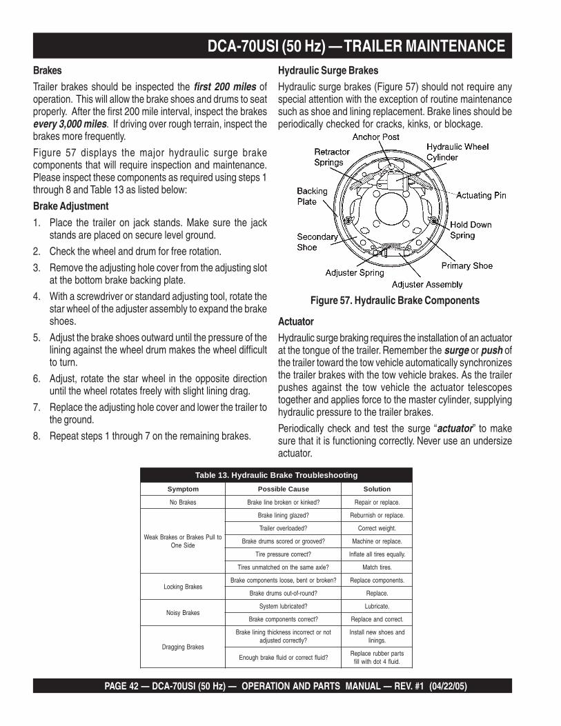
PAGE 42 — DCA-70USI (50 Hz) — OPERATION AND PARTS MANUAL — REV. #1 (04/22/05)
DCA-70USI (50 Hz) — TRAILER MAINTENANCEHydraulic Surge BrakesHydraulic surge brakes (Figure 57) should not require anyspecial attention with the exception of routine maintenancesuch as shoe and lining replacement. Brake lines should beperiodically checked for cracks, kinks, or blockage.
Figure 57. Hydraulic Brake Components
BrakesTrailer brakes should be inspected the first 200 miles ofoperation. This will allow the brake shoes and drums to seatproperly. After the first 200 mile interval, inspect the brakesevery 3,000 miles. If driving over rough terrain, inspect thebrakes more frequently.
Figure 57 displays the major hydraulic surge brakecomponents that will require inspection and maintenance.Please inspect these components as required using steps 1through 8 and Table 13 as listed below:
Brake Adjustment
1. Place the trailer on jack stands. Make sure the jackstands are placed on secure level ground.
2. Check the wheel and drum for free rotation.
3. Remove the adjusting hole cover from the adjusting slotat the bottom brake backing plate.
4. With a screwdriver or standard adjusting tool, rotate thestar wheel of the adjuster assembly to expand the brakeshoes.
5. Adjust the brake shoes outward until the pressure of thelining against the wheel drum makes the wheel difficultto turn.
6. Adjust, rotate the star wheel in the opposite directionuntil the wheel rotates freely with slight lining drag.
7. Replace the adjusting hole cover and lower the trailer tothe ground.
8. Repeat steps 1 through 7 on the remaining brakes.
ActuatorHydraulic surge braking requires the installation of an actuatorat the tongue of the trailer. Remember the surge or push ofthe trailer toward the tow vehicle automatically synchronizesthe trailer brakes with the tow vehicle brakes. As the trailerpushes against the tow vehicle the actuator telescopestogether and applies force to the master cylinder, supplyinghydraulic pressure to the trailer brakes.
Periodically check and test the surge “actuator” to makesure that it is functioning correctly. Never use an undersizeactuator.
gnitoohselbuorTekarBciluardyH.31elbaTmotpmyS esuaCelbissoP noituloS
sekarBoN ?deknikronekorbenilekarB .ecalperroriapeR
otlluPsekarBrosekarBkaeWediSenO
?dezalggninilekarB .ecalperrohsinrubeR
?dedaolrevoreliarT .thgiewtcerroC
?devoorgroderocssmurdekarB .ecalperroenihcaM
?tcerrocerusserperiT .yllauqeseritllaetalfnI
?elxaemasehtnodehctamnuseriT .serithctaM
sekarBgnikcoL?nekorbrotneb,esoolstnenopmocekarB .stnenopmocecalpeR
?dnuor-fo-tuosmurdekarB .ecalpeR
sekarBysioN?detacirbulmetsyS .etacirbuL
?tcerrocstnenopmocekarB .tcerrocdnaecalpeR
sekarBgniggarD
tonrotcerrocnissenkcihtgninilekarB?yltcerrocdetsujda
dnaseohswenllatsnI.sgninil
?diulftcerrocrodiulfekarbhguonEstraprebburecalpeR
.diulf4todhtiwllif
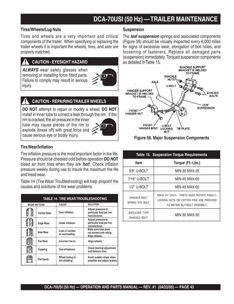
DCA-70USI (50 Hz) — OPERATION AND PARTS MANUAL — REV. #1 (04/22/05) — PAGE 43
1
Tires/Wheels/Lug NutsTires and wheels are a very important and criticalcomponents of the trailer. When specifying or replacing thetrailer wheels it is important the wheels, tires, and axle areproperly matched.
Tire Wear/InflationTire inflation pressure is the most important factor in tire life.Pressure should be checked cold before operation DO NOTbleed air from tires when they are hot!. Check inflationpressure weekly during use to insure the maximum tire lifeand tread wear.
Table 14 (Tire Wear Troubleshooting) will help pinpoint thecauses and solutions of tire wear problems.
SuspensionThe leaf suspension springs and associated components(Figure 58) should be visually inspected every 6,000 milesfor signs of excessive wear, elongation of bolt holes, andloosening of fasteners. Replace all damaged parts(suspension) immediately. Torqued suspension componentsas detailed in Table 15.
Figure 58. Major Suspension Components
DCA-70USI (50 Hz) — TRAILER MAINTENANCE
DO NOT attempt to repair or modify a wheel. DO NOTinstall in inner tube to correct a leak through the rim. If therim is cracked, the air pressure in the innertube may cause pieces of the rim toexplode (break off) with great force andcause serious eye or bodily injury.
CAUTION - REPAIRING TRAILER WHEELS
ALWAYS wear safety glasses whenremoving or installing force fitted parts.Failure to comply may result in seriousinjury.
CAUTION - EYESIGHT HAZARD
stnemeriuqeReuqroTnoisnepsuS.51elbaT
metI ).sbL-.tF(euqroT
TLOB-U"8/3 53-XAM03-NIM
TLOB-U"61/7 06-XAM54-NIM
TLOB-U"2/1 06-XAM54-NIM
SHACKLE BOLT
SPRING EYE BOLT
SNUG FIT ONLY. PARTS MUST ROTATE FREELY.LOCKING NUTS OR COTTER PINS ARE PROVIDED
TO RETAIN NUT-BOLT ASSEMBLY.
SHOULDER TYPE
SHACKLE BOLT05-XAM03-NIM

PAGE 44 — DCA-70USI (50 Hz) — OPERATION AND PARTS MANUAL — REV. #1 (04/22/05)
NEVER use an pneumatic airgun to tighten wheel lug nuts.
Figure 59. Wheel Lug NutsTightening Sequence
DCA-70USI (50 Hz) — TRAILER MAINTENANCE
NOTE
Lug Nut Torque RequirementsIt is extremely important to apply and maintain proper wheelmounting torque on the trailer. Be sure to use only thefasteners matched to the cone angle of the wheel. Properprocedure for attachment of the wheels is as follows:
1. Start all wheel lug nuts by hand.
2. Torque all lug nuts in sequence (see Figure 59). DO NOTtorque the wheel lug nuts all the way down. Tighten eachlug nut in 3 separate passes as defined by Table 16.
3. After first road use, retorque all lug nuts in sequence.Check all wheel lug nuts periodically.
stnemeriuqeReuqroTeriT.61elbaT
eziSleehW ssaPtsriFSBL-TF
ssaPdnoceSSBL-TF
ssaPdrihTSBL-TF
"21 52-02 04-53 56-05
"31 52-02 04-53 56-05
"41 52-02 06-05 021-09
"51 52-02 06-05 021-09
"61 52-02 06-05 021-09

DCA-70USI (50 Hz) — OPERATION AND PARTS MANUAL — REV. #1 (04/22/05) — PAGE 45
1
DCA-70USI (50 Hz) — TRAILER WIRING DIAGRAM
Figure 60. Trailer/Towing Vehicle Wiring Diagram

PAGE 46 — DCA-70USI (50 Hz) — OPERATION AND PARTS MANUAL — REV. #1 (04/22/05)
DCA-70USI (50 Hz) — GENERATOR WIRING DIAGRAM
Figure 61. Generator Wiring Diagram

DCA-70USI (50 Hz) — OPERATION AND PARTS MANUAL — REV. #1 (04/22/05) — PAGE 47
1
DCA-70USI (50 Hz) — ENGINE WIRING DIAGRAM
Figure 62. Engine Wiring Diagram

PAGE 48 — DCA-70USI (50 Hz) — OPERATION AND PARTS MANUAL — REV. #1 (04/22/05)
Practically all breakdowns can be prevented by proper handling and maintenance inspections, but in the event of abreakdown, use Table 17 shown below for diagnosis of the Generator. If the problem cannot be remedied, consult ourcompany's business office or service plant.
DCA-70USI (50 Hz) — TROUBLESHOOTING (GENERATOR)
GNITOOHSELBUORTROTARENEG.71ELBAT
MOTPMYS MELBORPELBISSOP NOITULOS
tuptuOegatloVoN ?evitcefedretemtloVCA .retemtlovagnisuegatlovtuptuokcehC
?esoolnoitcennocgniriwsI .riaperdnagniriwkcehC
?evitcefedRVAsI .yrassecenfiecalpeR
?reifitceRgnitatoRevitcefeD .ecalperdnakcehC
?dleiFreticxEevitcefeD 1NCnoK&Jssorcasmho3.71rofkcehC
tuptuOegatloVwoL ?tcerrocdeepsenignesI ."hgiH"otrevelelttorhtenignenruT
?esoolsnoitcennocgniriwsI .riaperdnagniriwkcehC
?RVAevitcefeD .yrassecenfiecalpeR
tuptuOegatloVhgiH ?esoolsnoitcennocgniriwsI .riaperdnagniriwkcehC
?RVAevitcefeD .yrassecenfiecalpeR
deppirTrekaerBtiucriC ?daolnitiucriCtrohS .riaperdnadaolkcehC
?tnerrucrevO .ecuderdnastnemeriuqerdaolmrifnoC
?rekaerbtiucricevitcefeD .ecalperdnakcehC
?detautcayaleRtnerrucrevO .ecalperdnatnemeriuqerdaolmrifnoC
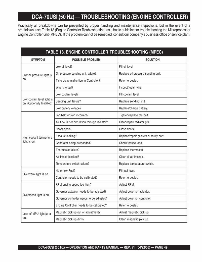
DCA-70USI (50 Hz) — OPERATION AND PARTS MANUAL — REV. #1 (04/22/05) — PAGE 49
1
DCA-70USI (50 Hz) — TROUBLESHOOTING (ENGINE CONTROLLER)Practically all breakdowns can be prevented by proper handling and maintenance inspections, but in the event of abreakdown, use Table 18 (Engine Controller Troubleshooting) as a basic guideline for troubleshooting the MicroprocessorEngine Controller unit (MPEC). If the problem cannot be remedied, consult our company's business office or service plant.
)CEPM(GNITOOHSELBUORTRELLORTNOCENIGNE.81ELBAT
MOTPMYS MELBORPELBISSOP NOITULOS
sithgilerusserpliowoL.no
?levelliowoL .levelliolliF
?eruliaftinugnidneserusserpliO .tinugnidneserusserplioecalpeR
?rellortnoCninoitnuflamyaledemiT .relaedotrefeR
?detrohseriW .eriwriaper/tcepsnI
sithgilleveltnaloocwoL)dellatsnIyllanoitpO(.no
?leveltnaloocwoL .leveltnalooclliF
?eruliaftinugnidneS .tinugnidnesecalpeR
?egatlovyrettabwoL .yrettabegrahc/ecalpeR
erutrepmettnaloochgiH.nosithgil
?tcerrocninoisnettlebnaF .tlebnafecalper/nethgiT
?rotaidarhguorhtnoitalucrictonsiwolfriA .llirgrotaidarriaper/naelC
?neposrooD .sroodesolC
?gnikaeltsuahxE .trapytluafrosteksagriaper/ecalpeR
?dedaolrevogniebrotareneG .daolecuder/kcehC
?eruliaftatsomrehT .tatsomrehtecalpeR
?dekcolbekatniriA .sekatniriallaraelC
?eruliafhctiwserutarepmeT .hctiwserutarepmetecalpeR
.nosithgilknarcrevO?leuFwolrooN .levelleuflliF
?detarbilacebotsdeenrellortnoC .relaedotrefeR
.nosithgildeepsrevO
?hgihootdeepsenigneMPR .MPRtsujdA
?detsujdaebotsdeenrotautcaronrevoG .rotautcaronrevogtsujdA
?detsujdaebotsdeenrellortnocronrevoG .rellortnocronrevogtsujdA
?detarbilacebotsdeenrellortnoCenignE .relaedotrefeR
ro)s(thgilUPMfossoL.no
?tnemtsujdafotuopukcipcitengaM .pukcipcitengamtsujdA
?ytridpukcipcitengaM .pukcipcitengamnaelC
PAGE 50 — DCA-70USI (50 Hz) — OPERATION AND PARTS MANUAL — REV. #1 (04/22/05)
EXPLANATION OF CODE IN REMARKS COLUMNHow to read the marks and remarks used in this parts book.
Items Found In the “Remarks” Column
Serial Numbers-Where indicated, this indicates a serialnumber range (inclusive) where a particular part is used.
Model Number-Where indicated, this shows that thecorresponding part is utilized only with this specific modelnumber or model number variant.
Items Found In the “Items Number” Column
All parts with same symbol in the number column, *, #, +,%, or <, belong to the same assembly or kit.
If more than one of the samereference number is listed, thelast one listed indicates newest(or latest) part available.
The contents of this catalogare subject to change withoutnotice.
NOTE
NOTE

DCA-70USI (50 Hz) — OPERATION AND PARTS MANUAL — REV. #1 (04/22/05) — PAGE 51
1
DCA-70USI (50 Hz) — SUGGESTED SPARE PARTS
Part number on this Suggested Spare Parts listmay supercede/replace the P/N shown in the textpages of this book.
NOTE
DCA-70USI (50 Hz) WHISPER WATTGENRATORW/ISUZU FF4BG1T DIESEL ENGINE
1 TO 3 UNITSQty. P/N Description
5 ......... 1132402311 ........ FILTER, OIL5 ......... 1132400791 ........ FILTER, FUEL, PRIMARY3 ......... 0602046365 ........ ELEMENT, AIR1 ......... 8972333820 ........ BELT, FAN1 ......... 0605505070 ........ CAP. FUEL TANK1 ......... 0602122272 ........ UNIT, OIL PRESSURE1 ......... 0602123260 ........ UNIT, WATER TEMPERATURE2 ......... 0601802149 ........ FUSE, 10A1 ......... 8971256000 ........ SENDER, WATER SWITCH (ENGINE SIDE)1 ......... 9827200690 ........ SENDER, OIL SWITCH (ENGINE SIDE)1 ......... 0605501079 ........ SENDER, FUEL SWITCH
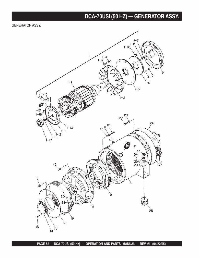
PAGE 52 — DCA-70USI (50 Hz) — OPERATION AND PARTS MANUAL — REV. #1 (04/22/05)
DCA-70USI (50 HZ) — GENERATOR ASSY.GENERATOR ASSY.
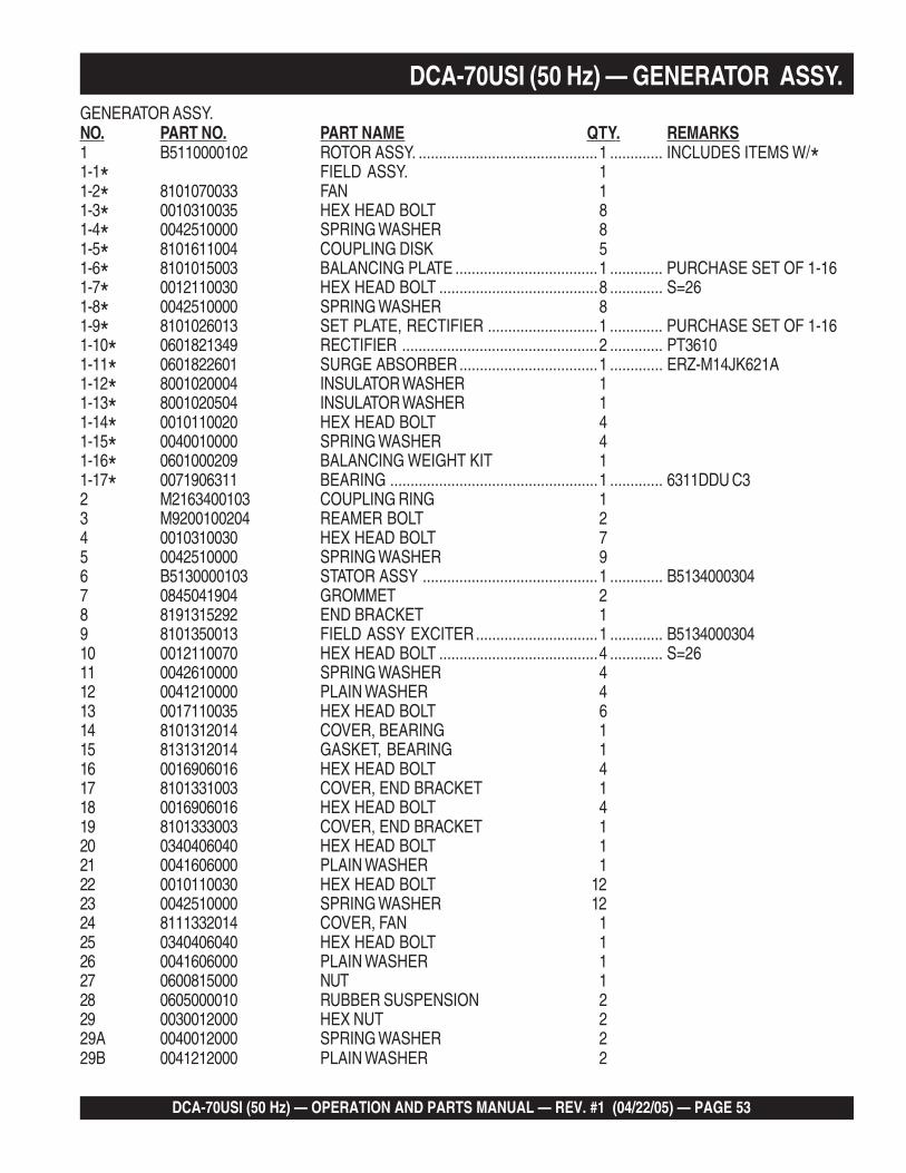
DCA-70USI (50 Hz) — OPERATION AND PARTS MANUAL — REV. #1 (04/22/05) — PAGE 53
1
DCA-70USI (50 Hz) — GENERATOR ASSY.GENERATOR ASSY.NO. PART NO. PART NAME QTY. REMARKS1 B5110000102 ROTOR ASSY. ............................................1 ............. INCLUDES ITEMS W/*1-1* FIELD ASSY. 11-2* 8101070033 FAN 11-3* 0010310035 HEX HEAD BOLT 81-4* 0042510000 SPRING WASHER 81-5* 8101611004 COUPLING DISK 51-6* 8101015003 BALANCING PLATE ...................................1 ............. PURCHASE SET OF 1-161-7* 0012110030 HEX HEAD BOLT .......................................8 ............. S=261-8* 0042510000 SPRING WASHER 81-9* 8101026013 SET PLATE, RECTIFIER ...........................1 ............. PURCHASE SET OF 1-161-10* 0601821349 RECTIFIER ................................................2 ............. PT36101-11* 0601822601 SURGE ABSORBER ..................................1 ............. ERZ-M14JK621A1-12* 8001020004 INSULATOR WASHER 11-13* 8001020504 INSULATOR WASHER 11-14* 0010110020 HEX HEAD BOLT 41-15* 0040010000 SPRING WASHER 41-16* 0601000209 BALANCING WEIGHT KIT 11-17* 0071906311 BEARING ...................................................1 ............. 6311DDU C32 M2163400103 COUPLING RING 13 M9200100204 REAMER BOLT 24 0010310030 HEX HEAD BOLT 75 0042510000 SPRING WASHER 96 B5130000103 STATOR ASSY ...........................................1 ............. B51340003047 0845041904 GROMMET 28 8191315292 END BRACKET 19 8101350013 FIELD ASSY EXCITER..............................1 ............. B513400030410 0012110070 HEX HEAD BOLT .......................................4 ............. S=2611 0042610000 SPRING WASHER 412 0041210000 PLAIN WASHER 413 0017110035 HEX HEAD BOLT 614 8101312014 COVER, BEARING 115 8131312014 GASKET, BEARING 116 0016906016 HEX HEAD BOLT 417 8101331003 COVER, END BRACKET 118 0016906016 HEX HEAD BOLT 419 8101333003 COVER, END BRACKET 120 0340406040 HEX HEAD BOLT 121 0041606000 PLAIN WASHER 122 0010110030 HEX HEAD BOLT 1223 0042510000 SPRING WASHER 1224 8111332014 COVER, FAN 125 0340406040 HEX HEAD BOLT 126 0041606000 PLAIN WASHER 127 0600815000 NUT 128 0605000010 RUBBER SUSPENSION 229 0030012000 HEX NUT 229A 0040012000 SPRING WASHER 229B 0041212000 PLAIN WASHER 2

PAGE 54 — DCA-70USI (50 Hz) — OPERATION AND PARTS MANUAL — REV. #1 (04/22/05)
DCA-70USI (50 Hz) — CONTROL BOX ASSY.CONTROL BOX ASSY.

DCA-70USI (50 Hz) — OPERATION AND PARTS MANUAL — REV. #1 (04/22/05) — PAGE 55
1
DCA-70USI (50 Hz) — CONTROL BOX ASSY.CONTROL BOX ASSY.
NO. PART NO. PART NAME QTY. REMARKS1 M2213001102 CONTROL BOX 12 0330000180 EDGING 33 0601870432 CIRCUIT BREAKER ........................................ 1 ............. FG3175WS02 175A3-1 0601870490 COVER, CIRCUIT BREAKER 24 0021004040 MACHINE SCREW 45 0601823863 RELAY UNIT ................................................... 2 ............. MSA9013A6 0027104016 MACHINE SCREW 47 0601820671 AUTOMATIC VOLTAGE REGULATOR.............. 1 ............. NTA-5A-2DB8 0027105016 MACHINE SCREW 49 0601806139 CURRENT TRANSFORMER ........................... 3 ............. 814-943 150/5A10 0027106016 MACHINE SCREW 611 0601820847 OVER CURRENT RELAY ................................ 1 ............. TA25DU4.012 0601820848 OVER CURRENT RELAY ................................ 1 ............. DB25/25A13 0027104016 MACHINE SCREW 213A 0207004000 HEX NUT 214 M2213500203 CONTROL BOX COVER 115 0016906016 HEX HEAD BOLT 416 M2270100004 SELECTOR SWITCH ...................................... 1 ............. VY-8016A M1201000004 KNOB, SELECTOR SWITCH17 M2213600803 SWITCH BRACKET 118 0330000320 EDGING 219 0027104010 MACHINE SCREW 420 0016906016 HEX HEAD BOLT 621 M2213600904 SWITCH COVER 122 0016906016 HEX HEAD BOLT 423 0015906016 HEX HEAD BOLT 823A 0040506000 TOOTHED WASHER 124 M2223000703 CONTROL PANEL 125 0601807641 FREQUENCY METER .................................... 1 ............. FCF-6 45~65Hz 240V26 0601808987 AC AMMETER ................................................ 1 ............. ACF-6 0~150A/300A:5A27 0601801040 CHANGE-OVER SWITCH, AMMETER ........... 1 ............. SL-2AS28 0601806859 AC VOLTMETER ............................................. 1 ............. SCF-6 0~600V29 0601801041 CHANGE-OVER SWITCH, VOLTMETER ........ 1 ............. SL-2VS30 0601840073 RHEOSTAT(VOLTAGE REGULATOR) .............. 1 ............. RA20A2SE102BJ 2W 1k OHM31 0601840121 KNOB 132 0602202545 CONTROLLER, 50 Hz 133 0601831340 SWITCH .......................................................... 1 ............. 7562K434 0027104040 MACHINE SCREW 234A 0207004000 HEX NUT 235 8941739480 CONTROL RESISTANCE ................................ 1 ............. REPLACES P/N 060220250636 0602120095 TACHOMETER ................................................ 1 ............. 111810

PAGE 56 — DCA-70USI (50 Hz) — OPERATION AND PARTS MANUAL — REV. #1 (04/22/05)
DCA-70USI (50 Hz) — CONTROL BOX ASSY. (CONT.)CONTROL BOX ASSY.
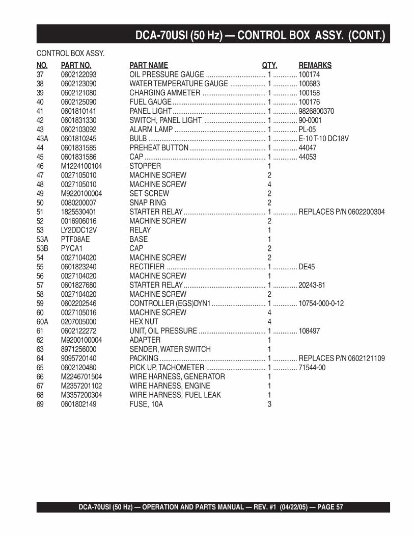
DCA-70USI (50 Hz) — OPERATION AND PARTS MANUAL — REV. #1 (04/22/05) — PAGE 57
1
DCA-70USI (50 Hz) — CONTROL BOX ASSY. (CONT.)CONTROL BOX ASSY.
NO. PART NO. PART NAME QTY. REMARKS37 0602122093 OIL PRESSURE GAUGE ................................ 1 ............. 10017438 0602123090 WATER TEMPERATURE GAUGE ................... 1 ............. 10068339 0602121080 CHARGING AMMETER .................................. 1 ............. 10015840 0602125090 FUEL GAUGE.................................................. 1 ............. 10017641 0601810141 PANEL LIGHT.................................................. 1 ............. 982680037042 0601831330 SWITCH, PANEL LIGHT ................................. 1 ............. 90-000143 0602103092 ALARM LAMP ................................................. 1 ............. PL-0543A 0601810245 BULB ............................................................... 1 ............. E-10 T-10 DC18V44 0601831585 PREHEAT BUTTON......................................... 1 ............. 4404745 0601831586 CAP ................................................................. 1 ............. 4405346 M1224100104 STOPPER 147 0027105010 MACHINE SCREW 248 0027105010 MACHINE SCREW 449 M9220100004 SET SCREW 250 0080200007 SNAP RING 251 1825530401 STARTER RELAY............................................ 1 ............. REPLACES P/N 060220030452 0016906016 MACHINE SCREW 253 LY2DDC12V RELAY 153A PTF08AE BASE 153B PYCA1 CAP 254 0027104020 MACHINE SCREW 255 0601823240 RECTIFIER ..................................................... 1 ............. DE4556 0027104020 MACHINE SCREW 157 0601827680 STARTER RELAY............................................ 1 ............. 20243-8158 0027104020 MACHINE SCREW 259 0602202546 CONTROLLER (EGS)DYN1............................. 1 ............. 10754-000-0-1260 0027105016 MACHINE SCREW 460A 0207005000 HEX NUT 461 0602122272 UNIT, OIL PRESSURE .................................... 1 ............. 10849762 M9200100004 ADAPTER 163 8971256000 SENDER, WATER SWITCH 164 9095720140 PACKING ......................................................... 1 ............. REPLACES P/N 060212110965 0602120480 PICK UP, TACHOMETER ................................ 1 ............. 71544-0066 M2246701504 WIRE HARNESS, GENERATOR 167 M2357201102 WIRE HARNESS, ENGINE 168 M3357200304 WIRE HARNESS, FUEL LEAK 169 0601802149 FUSE, 10A 3

PAGE 58 — DCA-70USI (50 Hz) — OPERATION AND PARTS MANUAL — REV. #1 (04/22/05)
DCA-70USI (50 Hz) — ENGINE AND RADIATOR ASSY.ENGINE AND RADIATOR ASSY.
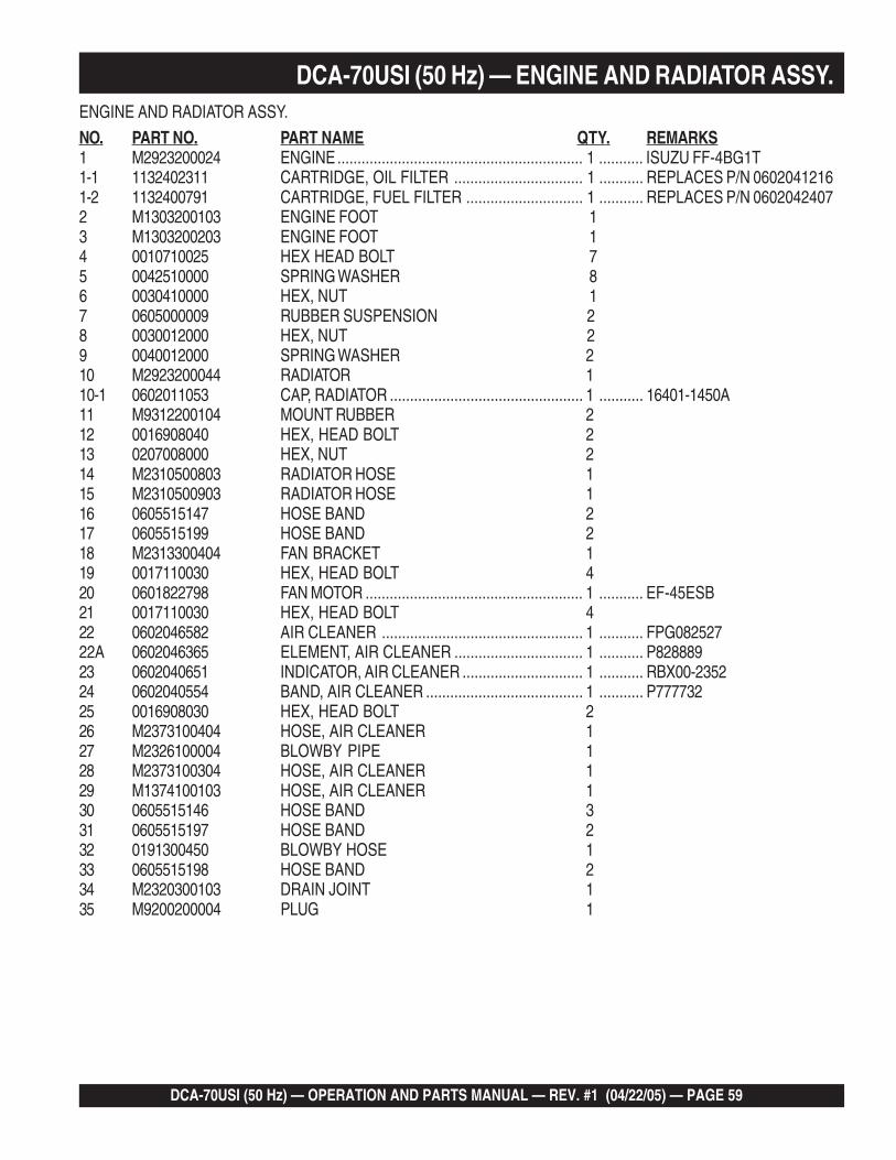
DCA-70USI (50 Hz) — OPERATION AND PARTS MANUAL — REV. #1 (04/22/05) — PAGE 59
1
DCA-70USI (50 Hz) — ENGINE AND RADIATOR ASSY.ENGINE AND RADIATOR ASSY.
NO. PART NO. PART NAME QTY. REMARKS1 M2923200024 ENGINE............................................................. 1 ........... ISUZU FF-4BG1T1-1 1132402311 CARTRIDGE, OIL FILTER ................................ 1 ........... REPLACES P/N 06020412161-2 1132400791 CARTRIDGE, FUEL FILTER ............................. 1 ........... REPLACES P/N 06020424072 M1303200103 ENGINE FOOT 13 M1303200203 ENGINE FOOT 14 0010710025 HEX HEAD BOLT 75 0042510000 SPRING WASHER 86 0030410000 HEX, NUT 17 0605000009 RUBBER SUSPENSION 28 0030012000 HEX, NUT 29 0040012000 SPRING WASHER 210 M2923200044 RADIATOR 110-1 0602011053 CAP, RADIATOR ................................................ 1 ........... 16401-1450A11 M9312200104 MOUNT RUBBER 212 0016908040 HEX, HEAD BOLT 213 0207008000 HEX, NUT 214 M2310500803 RADIATOR HOSE 115 M2310500903 RADIATOR HOSE 116 0605515147 HOSE BAND 217 0605515199 HOSE BAND 218 M2313300404 FAN BRACKET 119 0017110030 HEX, HEAD BOLT 420 0601822798 FAN MOTOR ...................................................... 1 ........... EF-45ESB21 0017110030 HEX, HEAD BOLT 422 0602046582 AIR CLEANER .................................................. 1 ........... FPG08252722A 0602046365 ELEMENT, AIR CLEANER ................................ 1 ........... P82888923 0602040651 INDICATOR, AIR CLEANER .............................. 1 ........... RBX00-235224 0602040554 BAND, AIR CLEANER ....................................... 1 ........... P77773225 0016908030 HEX, HEAD BOLT 226 M2373100404 HOSE, AIR CLEANER 127 M2326100004 BLOWBY PIPE 128 M2373100304 HOSE, AIR CLEANER 129 M1374100103 HOSE, AIR CLEANER 130 0605515146 HOSE BAND 331 0605515197 HOSE BAND 232 0191300450 BLOWBY HOSE 133 0605515198 HOSE BAND 234 M2320300103 DRAIN JOINT 135 M9200200004 PLUG 1
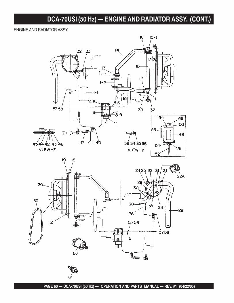
PAGE 60 — DCA-70USI (50 Hz) — OPERATION AND PARTS MANUAL — REV. #1 (04/22/05)
DCA-70USI (50 Hz) — ENGINE AND RADIATOR ASSY. (CONT.)ENGINE AND RADIATOR ASSY.
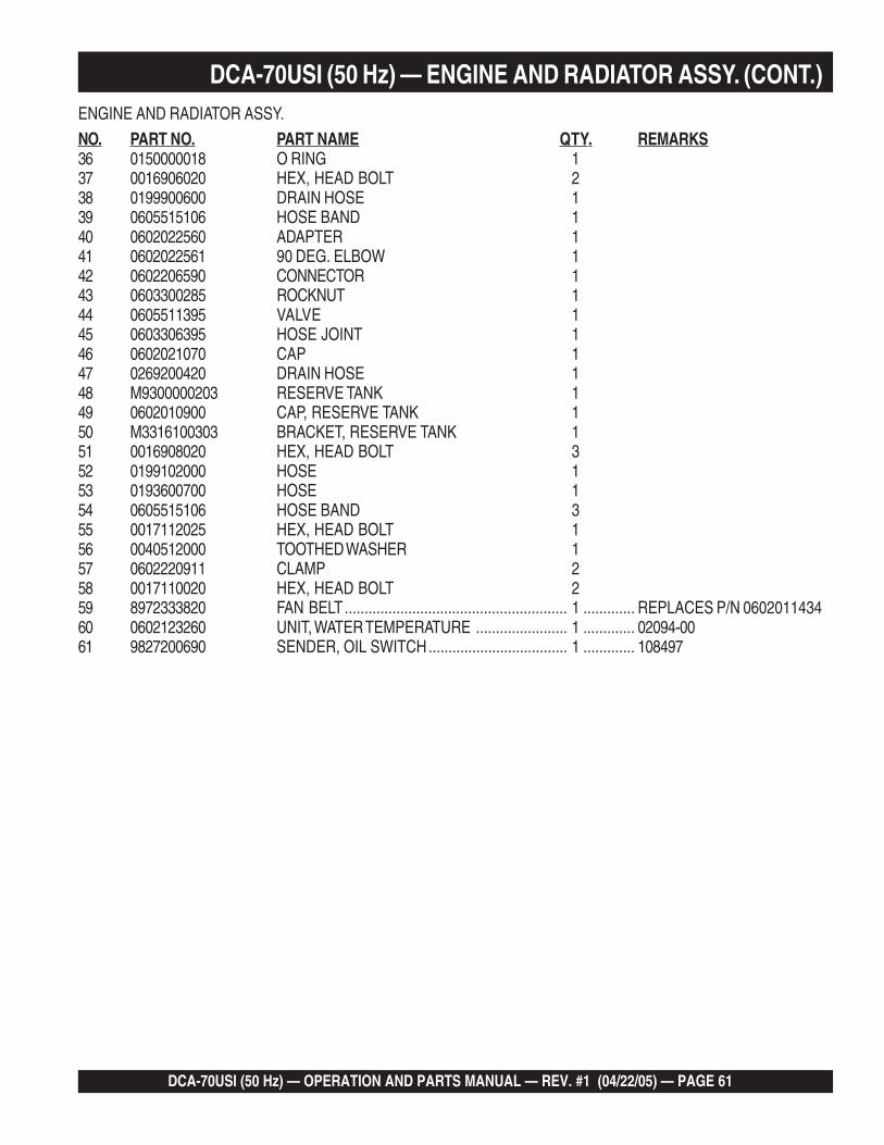
DCA-70USI (50 Hz) — OPERATION AND PARTS MANUAL — REV. #1 (04/22/05) — PAGE 61
1
DCA-70USI (50 Hz) — ENGINE AND RADIATOR ASSY. (CONT.)ENGINE AND RADIATOR ASSY.
NO. PART NO. PART NAME QTY. REMARKS36 0150000018 O RING 137 0016906020 HEX, HEAD BOLT 238 0199900600 DRAIN HOSE 139 0605515106 HOSE BAND 140 0602022560 ADAPTER 141 0602022561 90 DEG. ELBOW 142 0602206590 CONNECTOR 143 0603300285 ROCKNUT 144 0605511395 VALVE 145 0603306395 HOSE JOINT 146 0602021070 CAP 147 0269200420 DRAIN HOSE 148 M9300000203 RESERVE TANK 149 0602010900 CAP, RESERVE TANK 150 M3316100303 BRACKET, RESERVE TANK 151 0016908020 HEX, HEAD BOLT 352 0199102000 HOSE 153 0193600700 HOSE 154 0605515106 HOSE BAND 355 0017112025 HEX, HEAD BOLT 156 0040512000 TOOTHED WASHER 157 0602220911 CLAMP 258 0017110020 HEX, HEAD BOLT 259 8972333820 FAN BELT........................................................ 1 ............. REPLACES P/N 060201143460 0602123260 UNIT, WATER TEMPERATURE ....................... 1 ............. 02094-0061 9827200690 SENDER, OIL SWITCH................................... 1 ............. 108497
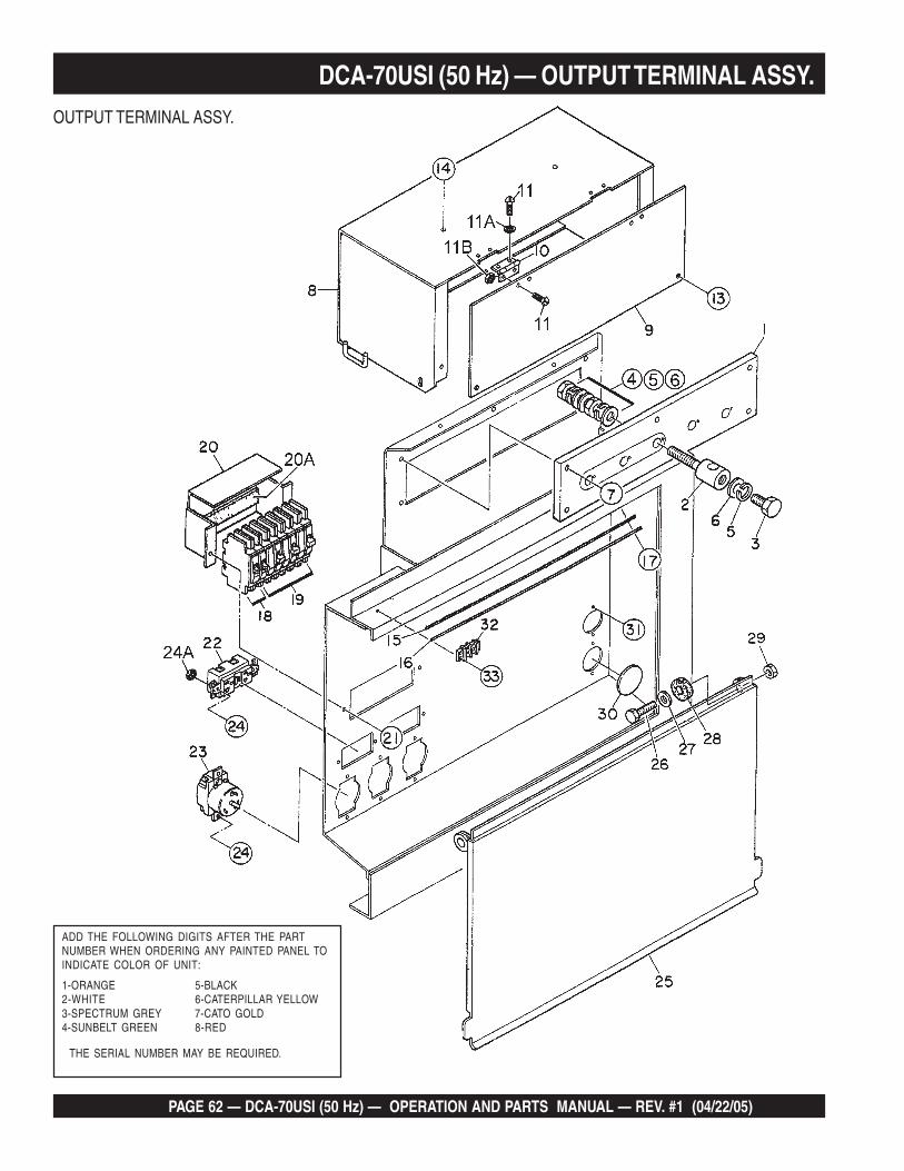
PAGE 62 — DCA-70USI (50 Hz) — OPERATION AND PARTS MANUAL — REV. #1 (04/22/05)
DCA-70USI (50 Hz) — OUTPUT TERMINAL ASSY.OUTPUT TERMINAL ASSY.
THE SERIAL NUMBER MAY BE REQUIRED.
ADD THE FOLLOWING DIGITS AFTER THE PARTNUMBER WHEN ORDERING ANY PAINTED PANEL TOINDICATE COLOR OF UNIT:
1-ORANGE 5-BLACK2-WHITE 6-CATERPILLAR YELLOW3-SPECTRUM GREY 7-CATO GOLD4-SUNBELT GREEN 8-RED

DCA-70USI (50 Hz) — OPERATION AND PARTS MANUAL — REV. #1 (04/22/05) — PAGE 63
1
DCA-70USI (50 Hz) — OUTPUT TERMINAL ASSY.OUTPUT TERMINAL ASSY.
NO. PART NO. PART NAME QTY. REMARKS1 M2230700113 TERMINAL PANEL 12 M2233000004 OUTPUT TERMINAL BOLT 53 M2233100004 TIE BOLT 54 0039312000 HEX, NUT 105 0040012000 SPRING WASHER 156 0041412000 PLAIN WASHER 207 0016908035 HEX, HEAD BOLT 58 M3236100503 TERMINAL COVER 19 M3236100404 OUTPUT WINDOW 110 0605010040 HINGE 211 0027103010 MACHINE SCREW 411A 0030003000 HEX, NUT 411B 0041203000 PLAIN WASHER 412 0027103010 MACHINE SCREW 412A 0030003000 HEX, NUT 413 0016906020 HEX, HEAD BOLT 214 0016906016 HEX, HEAD BOLT 415 M3236400004 CABLE OUTLET COVER 116 M3236300004 SUPPORTER, CABLE OUTLET COVER 117 0016906020 HEX, HEAD BOLT 618 0601870440 CIRCUIT BREAKER ........................................ 2 ............. QCF 1020 1P 20A19 0601870441 CIRCUIT BREAKER ........................................ 3 ............. QCF 2050 2P 50A20 M1260700504 BREAKER FITTING COVER 120A 0222100100 CUSHION RUBBER 221 0016906020 HEX, HEAD BOLT 222 0601812598 RECEPTACLE ................................................. 2 ............. GF53OEM 125V 20AX223 0601812538 RECEPTACLE ................................................. 3 ............. CS6369 250V 50A24 0027104016 MACHINE SCREW 1024A 0207004000 HEX, NUT 1025 M2236100603 TERMINAL COVER 126 0010112045 HEX, HEAD BOLT 227 0041212000 PLAIN WASHER 228 M9310200004 STAY RUBBER 229 0030012000 HEX, NUT 230 0603306775 BLIND PLUG 231 0027104016 MACHINE SCREW 432 0601815194 TERMINAL 133 0027104016 MACHINE SCREW 2
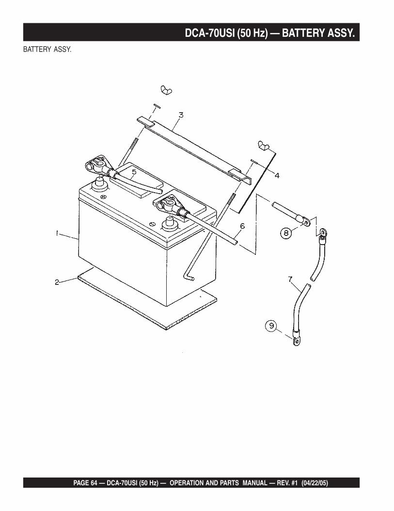
PAGE 64 — DCA-70USI (50 Hz) — OPERATION AND PARTS MANUAL — REV. #1 (04/22/05)
DCA-70USI (50 Hz) — BATTERY ASSY.BATTERY ASSY.

DCA-70USI (50 Hz) — OPERATION AND PARTS MANUAL — REV. #1 (04/22/05) — PAGE 65
1
DCA-70USI (50 Hz) — BATTERY ASSY.BATTERY ASSY.
NO. PART NO. PART NAME QTY. REMARKS1 0602220187 BATTERY ........................................................ 1 ............. 627MFD2 M9210500014 BATTERY SHEET 13 M9103000304 BATTERY BAND 14 0602220920 BATTERY BOLT SET ...................................... 2 ............. BHL-10J 1/4-L105 M2346900404 BATTERY CABLE 16 M2346900104 BATTERY CABLE 17 CABLE ............................................................ 1 ............. MAKE LOCALLY8 0017112025 HEX, HEAD BOLT 1
0040512000 TOOTHED WASHER 19 0040520000 TOOTHED WASHER 1

PAGE 66 — DCA-70USI (50 Hz) — OPERATION AND PARTS MANUAL — REV. #1 (04/22/05)
DCA-70USI (50 Hz) — MUFFLER ASSY.MUFFLER ASSY.

DCA-70USI (50 Hz) — OPERATION AND PARTS MANUAL — REV. #1 (04/22/05) — PAGE 67
1
DCA-70USI (50 Hz) — MUFFLER ASSY.MUFFLER ASSY.
NO. PART NO. PART NAME QTY. REMARKS1 M2330101003 MUFFLER 12 0017112030 HEX, HEAD BOLT 43 M233000903 EXHAUST PIPE 14 M2333200404 GASKET 15 0017110040 HEX, HEAD BOLT 46 M2333200304 GASKET 17 0017110035 HEX, HEAD BOLT 48 M2333000803 EXHAUST PIPE 19 0017110050 HEX, HEAD BOLT 410 3943690210 GASKET ......................................................... 1 ............. REPLACES P/N 060232010111 0039308000 HEX, NUT 6

PAGE 68 — DCA-70USI (50 Hz) — OPERATION AND PARTS MANUAL — REV. #1 (04/22/05)
DCA-70USI (50 Hz) — FUEL TANK ASSY.
FUEL TANK ASSY.

DCA-70USI (50 Hz) — OPERATION AND PARTS MANUAL — REV. #1 (04/22/05) — PAGE 69
1
DCA-70USI (50 Hz) — FUEL TANK ASSY.
FUEL TANK ASSY.
NO. PART NO. PART NAME QTY. REMARKS1 M2363001202 FUEL TANK 11A 0605505070 FUEL TANK CAP 11B 0605501079 FUEL SENDER UNIT 11C 0605516090 GASKET 12 M2363200704 TANK BAND 63 M9310500104 SUPPORTER SHEET 64 0016908020 HEX, HEAD BOLT 65 0016908055 HEX, HEAD BOLT 35A 0207008000 HEX, NUT 96 0191302200 VENT HOSE 17 0605515109 HOSE BAND 28 0191300900 SUCTION HOSE 19 0191301100 RETURN HOSE 110 0605515109 HOSE BAND 411 0222100710 TANK SHEET 5

PAGE 70 — DCA-70USI (50 Hz) — OPERATION AND PARTS MANUAL — REV. #1 (04/22/05)
THE SERIAL NUMBER MAY BE REQUIRED.
ADD THE FOLLOWING DIGITS AFTER THE PARTNUMBER WHEN ORDERING ANY PAINTED PANEL TOINDICATE COLOR OF UNIT:
1-ORANGE 5-BLACK2-WHITE 6-CATERPILLAR YELLOW3-SPECTRUM GREY 7-CATO GOLD4-SUNBELT GREEN 8-RED
DCA-70USI (50 Hz) — ENCLOSURE #1 ASSY.ENCLOSURE #1 ASSY.

DCA-70USI (50 Hz) — OPERATION AND PARTS MANUAL — REV. #1 (04/22/05) — PAGE 71
1
DCA-70USI (50 Hz) — ENCLOSURE #1 ASSY.ENCLOSURE #1 ASSY.
NO. PART NO. PART NAME QTY. REMARKS1 M2413001702 BASE 12 M2363300603 ENVIRONMENTAL TANK 13 0016910030 HEX, HEAD BOLT 124 0603306797 PLUG 15 M2423001302 FRONT FRAME 15A M2493104603 ACOUSTIC SHEET 16 M2423001402 FRONT FRAME 16A M2493104603 ACOUSTIC SHEET 17 0601850265 GROMMET 18 0601850263 GROMMET 19 0601851736 GROMMET 110 0601851739 GROMMET 111 0016908020 HEX, HEAD BOLT 2012 0016910025 HEX, HEAD BOLT 613 M2310600204 HOSE COVER 114 M2310600304 HOSE COVER 115 M2310600004 HOSE COVER 116 0016906020 HEX, HEAD BOLT 1217 M3423200704 DUCT COVER 218 0016906020 HEX, HEAD BOLT 1419 M3423200804 DUCT COVER 120 0016906016 HEX, HEAD BOLT 621 M2310300704 FAN SHROUD 122 M2310300804 FAN SHROUD 123 M2310300904 FAN SHROUD 124 0016906020 HEX, HEAD BOLT 1425 M2423300204 DISCHARGE GUIDE 125A M2493104504 ACOUSTIC SHEET 126 0016908020 HEX, HEAD BOLT 627 M243202004 COVER, FRONT FRAME 127A M2493104304 ACOUSTIC SHEET 128 0019208020 HEX, HEAD BOLT 2529 M2433000803 CENTER FRAME 129A M2493200004 ACOUSTIC SHEET 130 0010114040 HEX, HEAD BOLT 430A 0030014000 HEX, NUT 430B 0040014000 SPRING WASHER 430C 0041214000 PLAIN WASHER 8

PAGE 72 — DCA-70USI (50 Hz) — OPERATION AND PARTS MANUAL — REV. #1 (04/22/05)
DCA-70USI (50 Hz) — ENCLOSURE #1 ASSY. (CONT.)
THE SERIAL NUMBER MAY BE REQUIRED.
ADD THE FOLLOWING DIGITS AFTER THE PARTNUMBER WHEN ORDERING ANY PAINTED PANEL TOINDICATE COLOR OF UNIT:
1-ORANGE 5-BLACK2-WHITE 6-CATERPILLAR YELLOW3-SPECTRUM GREY 7-CATO GOLD4-SUNBELT GREEN 8-RED
ENCLOSURE #1 ASSY.

DCA-70USI (50 Hz) — OPERATION AND PARTS MANUAL — REV. #1 (04/22/05) — PAGE 73
1
ENCLOSURE (PART 1) ASSY.
NO. PART NO. PART NAME QTY. REMARKS31 0010120050 HEX, HEAD BOLT 431A 0030020000 HEX, NUT 431B 0040020000 SPRING WASHER 431C 0041220000 PLAIN WASHER 832 M2463100302 ROOF PANEL 132A M2493502604 ACOUSTIC SHEET 133 M2463200302 ROOF PANEL 133A M2493502403 ACOUSTIC SHEET 134 M3463200704 BACK PLATE 235 0016906016 HEX, HEAD BOLT 1236 M2463200503 DUCT 136A M2493502704 ACOUSTIC SHEET 137 0016908020 HEX, HEAD BOLT 1038 M2463400103 DUCT COVER 139 0016908020 HEX, HEAD BOLT 640 M2423201504 OVER COVER, FRONT FRAME 140A M2493104404 ACOUSTIC SHEET 141 0019208020 HEX, HEAD BOLT 4242 0019210025 HEX, HEAD BOLT 843 M3310600004 COVER, RADIATOR CAP 144 0019208020 HEX, HEAD BOLT 445 M2483100304 COVER, EXHAUST PIPE 146 0016908020 HEX, HEAD BOLT 247 0016908020 HEX, HEAD BOLT 147A 0040508000 TOOTHED WASHER 148 0605503062 FUEL LEAK DETECTED SWITCH 149 M1414800104 BRACKET 150 0017108020 HEX, HEAD BOLT 2
DCA-70USI (50 Hz) — ENCLOSURE #1 ASSY. (CONT.)
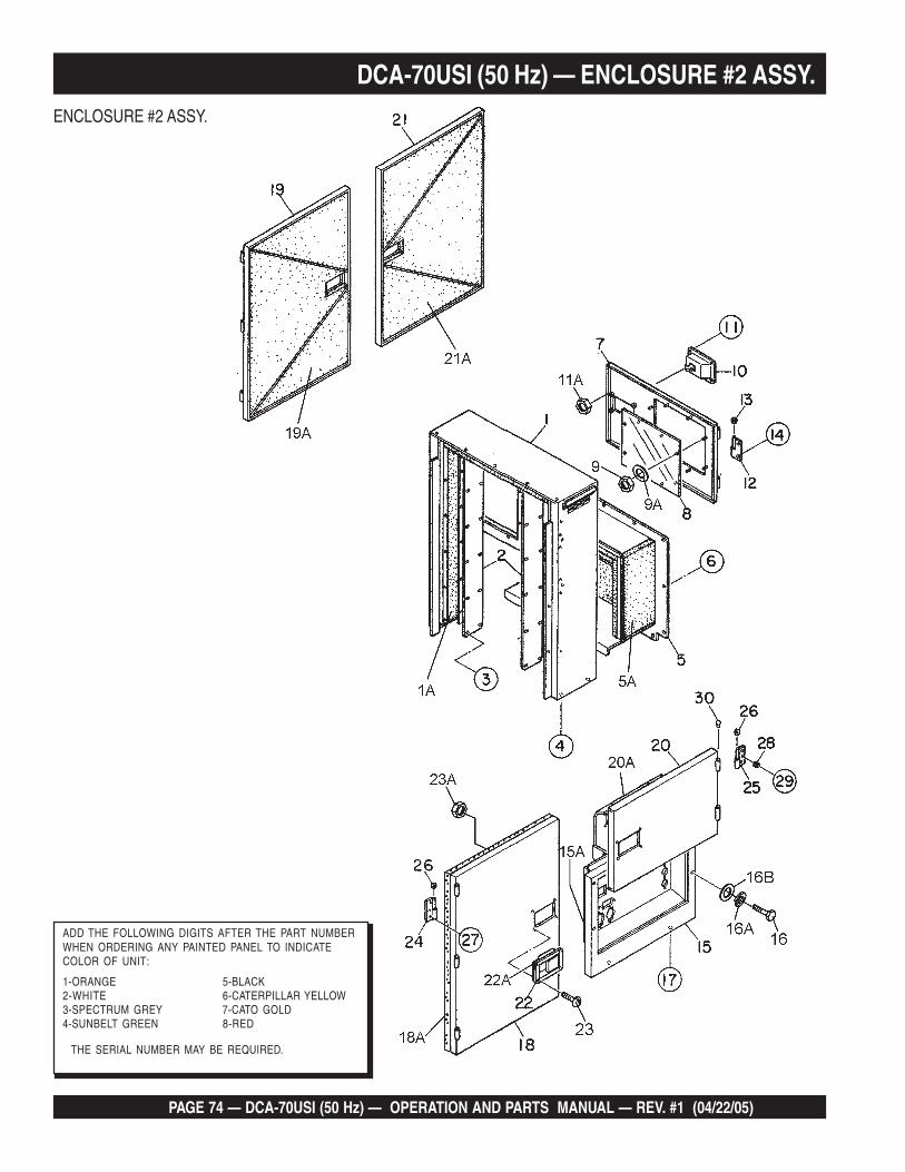
PAGE 74 — DCA-70USI (50 Hz) — OPERATION AND PARTS MANUAL — REV. #1 (04/22/05)
DCA-70USI (50 Hz) — ENCLOSURE #2 ASSY.ENCLOSURE #2 ASSY.
THE SERIAL NUMBER MAY BE REQUIRED.
ADD THE FOLLOWING DIGITS AFTER THE PART NUMBERWHEN ORDERING ANY PAINTED PANEL TO INDICATECOLOR OF UNIT:
1-ORANGE 5-BLACK2-WHITE 6-CATERPILLAR YELLOW3-SPECTRUM GREY 7-CATO GOLD4-SUNBELT GREEN 8-RED

DCA-70USI (50 Hz) — OPERATION AND PARTS MANUAL — REV. #1 (04/22/05) — PAGE 75
1
DCA-70USI (50 Hz) — ENCLOSURE #2 ASSY.ENCLOSURE #2 ASSY.
NO. PART NO. PART NAME QTY. REMARKS1 M2443000802 REAR FRAME 11A M2493303103 ACOUSTIC SHEET 12 M2443000604 DUCT 23 0016908020 HEX, HEAD BOLT 244 0016910025 HEX, HEAD BOLT 45 M2443301103 COVER, REAR FRAME 15A M2493303004 ACOUSTIC SHEET 16 0019208020 HEX, HEAD BOLT 127 M2443200303 DOOR, REAR FRAME 18 M1444600004 WINDOW PLATE 19 0207006000 HEX, NUT 89A 0041206000 PLAIN WASHER 810 M9113000002 DOOR HANDLE ASSY 111 0021806016 MACHINE SCREW 411A 0030006000 HEX, NUT 412 M9110100204 HINGE 213 M9116100004 WASHER 214 0019208020 HEX, HEAD BOLT 315 M2453201202 SPLASHER PANEL 115A M2493405204 ACOUSTIC SHEET 116 0019108065 HEX, HEAD BOLT 416A 0042308000 SPRING WASHER 416B 0042408000 PLAIN WASHER 417 0016910025 HEX, HEAD BOLT 218 M2453001703 SIDE DOOR 118A M2493404704 ACOUSTIC SHEET 119 M2453001803 SIDE DOOR 119A M2493405104 ACOUSTIC SHEET 120 M2453001903 SIDE DOOR 120A M2493405304 ACOUSTIC SHEET 121 M2453001703 SIDE DOOR 121A M2493404704 ACOUSTIC SHEET 122 M9113000002 DOOR HANDLE ASSY 422A C9312500004 SEAL RUBBER 423 0021806016 MACHINE SCREW 1623A 0030006000 HEX, NUT 1624 M9110100804 HINGE 625 M9110100904 HINGE 526 M9116100004 WASHER 1127 0019208020 HEX, HEAD BOLT 2628 0601850097 STOPPER 829 0027208025 MACHINE SCREW 830 M9310000004 CAP 13

PAGE 76 — DCA-70USI (50 Hz) — OPERATION AND PARTS MANUAL — REV. #1 (04/22/05)
DCA-70USI (50 Hz) — RUBBER SEALS ASSY.RUBBER SEALS ASSY.

DCA-70USI (50 Hz) — OPERATION AND PARTS MANUAL — REV. #1 (04/22/05) — PAGE 77
1
DCA-70USI (50 Hz) — RUBBER SEALS ASSY.RUBBER SEALS ASSY.
NO. PART NO. PART NAME QTY. REMARKS1 0229200840 RUBBER SEAL 12 0314502250 RUBBER SEAL 13 0229200950 RUBBER SEAL 34 0229200125 RUBBER SEAL 45 0228901165 RUBBER SEAL 36 0228900770 RUBBER SEAL 87 0228901105 RUBBER SEAL 38 0228900535 RUBBER SEAL 19 0228900475 RUBBER SEAL 110 0229200910 RUBBER SEAL 111 0228800525 RUBBER SEAL 112 0228800790 RUBBER SEAL 213 0228800475 RUBBER SEAL 114 0228100325 RUBBER SEAL 215 0228100420 RUBBER SEAL 2

PAGE 78 — DCA-70USI (50 Hz) — OPERATION AND PARTS MANUAL — REV. #1 (04/22/05)
DCA-70USI (50 Hz) — NAME PLATE AND DECALS ASSY.NAMEPLATE AND DECALS ASSY.
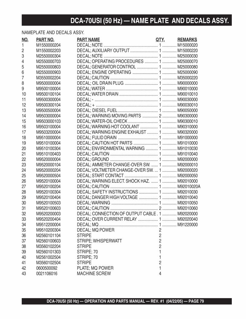
DCA-70USI (50 Hz) — OPERATION AND PARTS MANUAL — REV. #1 (04/22/05) — PAGE 79
1
DCA-70USI (50 Hz) — NAME PLATE AND DECALS ASSY.
NAMEPLATE AND DECALS ASSY.
NO. PART NO. PART NAME QTY. REMARKS1 M1550000204 DECAL; NOTE ................................................. 1 ............. M150000202 M1550002203 DECAL; AUXILIARY OUTPUT ......................... 1 ............. M150002203 M2550000304 DECAL; NOTE ................................................. 1 ............. M250000304 M2550000703 DECAL; OPERATING PROCEDURES ............ 1 ............. M250000705 M2550000803 DECAL; GENERATOR CONTROL ................... 1 ............. M250000806 M2550000903 DECAL; ENGINE OPERATING ....................... 1 ............. M250000907 M3550002204 DECAL; CAUTION ........................................... 1 ............. M350002208 M9500000004 DECAL; OIL DRAIN PLUG .............................. 1 ............. M900000009 M9500100004 DECAL; WATER ............................................... 1 ............. M9001000010 M9500100104 DECAL; WATER DRAIN ................................... 1 ............. M9001001011 M9500300004 DECAL; - ......................................................... 1 ............. M9003000012 M9500300104 DECAL; + ........................................................ 1 ............. M9003001013 M9500500004 DECAL; DIESEL FUEL .................................... 1 ............. M9005000014 M9503000004 DECAL; WARNING MOVING PARTS .............. 2 ............. M9030000015 M9503000103 DECAL; WATER-OIL CHECK ........................... 1 ............. M9030001016 M9503100004 DECAL; WARNING HOT COOLANT ................ 1 ............. M9031000017 M9503200004 DECAL; WARNING ENGINE EXHAUST .......... 1 ............. M9032000018 M9510000004 DECAL; FULID DRAIN .................................... 1 ............. M9100000019 M9510100004 DECAL; CAUTION HOT PARTS ...................... 1 ............. M9101000020 M9510100304 DECAL; ENVIRONMENTAL WARNING ........... 1 ............. M9101003021 M9510100403 DECAL; CAUTION ........................................... 1 ............. M9101004022 M9520000004 DECAL; GROUND ........................................... 1 ............. M9200000023 M9520000104 DECAL; AMMETER CHANGE-OVER SW. ...... 1 ............. M9200001024 M9520000204 DECAL; VOLTMETER CHANGE-OVER SW. ... 1 ............. M9200002025 M9520000504 DECAL; START CONTACT .............................. 1 ............. M9200005026 M9520100004 DECAL; WARNING ELECT. SHOCK HAZ. ...... 1 ............. M9201000027 M9520100204 DECAL; CAUTION ........................................... 1 ............. M92010020A28 M9520100304 DECAL; SAFETY INSTRUCTIONS ................. 1 ............. M9201003029 M9520100404 DECAL; DANGER HIGH VOLTAGE ................. 1 ............. M9201004030 M9520100503 DECAL; WARNING .......................................... 1 ............. M9201005031 M9520100603 DECAL; CAUTION ........................................... 2 ............. M9201006032 M9520200003 DECAL; CONNECTION OF OUTPUT CABLE . 1 ............. M9202000033 M9520200404 DECAL; OVER CURRENT RELAY .................. 1 ............. M9202004034 M9512200004 DECAL; MQ ..................................................... 1 ............. M9122000035 M9510200304 DECAL; MQ POWER 236 M2560101104 STRIPE 237 M2560100603 STRIPE; WHISPERWATT 238 M3560102204 STRIPE 239 M2560101303 STRIPE; 70 140 M2561002504 STRIPE; 70 141 M3560102504 STRIPE 242 0600500092 PLATE; MQ POWER 143 0021106016 MACHINE SCREW 4

PAGE 80 — DCA-70USI (50 Hz) — OPERATION AND PARTS MANUAL — REV. #1 (04/22/05)
TERMS AND CONDITIONS OF SALE — PARTSPAYMENT TERMS
Terms of payment for parts are net 10 days.
FREIGHT POLICY
All parts orders will be shipped collect orprepaid with the charges added to the invoice.All shipments are F.O.B. point of origin.Multiquip’s responsibility ceases when a signedmanifest has been obtained from the carrier,and any claim for shortage or damage must besettled between the consignee and the carrier.
MINIMUM ORDER
The minimum charge for orders from Multiquipis $15.00 net. Customers will be asked forinstructions regarding handling of orders notmeeting this requirement.
RETURNED GOODS POLICY
Return shipments will be accepted and creditwill be allowed, subject to the following provi-sions:
1. A Returned Material Authorization mustbe approved by Multiquip prior to ship-ment.
2. To obtain a Return Material Authorization,a list must be provided to Multiquip PartsSales that defines item numbers, quanti-ties, and descriptions of the items to bereturned.
a. The parts numbers and descriptionsmust match the current parts pricelist.
b. The list must be typed or computergenerated.
c. The list must state the reason(s) forthe return.
d. The list must reference the salesorder(s) or invoice(s) under which theitems were originally purchased.
e. The list must include the name andphone number of the person request-ing the RMA.
3. A copy of the Return Material Authoriza-tion must accompany the return shipment.
4. Freight is at the sender’s expense. Allparts must be returned freight prepaid toMultiquip’s designated receiving point.
5. Parts must be in new and resalable con-dition, in the original Multiquip package (ifany), and with Multiquip part numbersclearly marked.
6. The following items are not returnable:
a. Obsolete parts. (If an item is in theprice book and shows as beingreplaced by another item, it isobsolete.)
b. Any parts with a limited shelf life(such as gaskets, seals, “O” rings,and other rubber parts) that were pur-chased more than six months prior tothe return date.
c. Any line item with an extended dealernet price of less than $5.00.
d. Special order items.
e. Electrical components.
f. Paint, chemicals, and lubricants.
g. Decals and paper products.
h. Items purchased in kits.
7. The sender will be notified of anymaterial received that is not acceptable.
8. Such material will be held for fiveworking days from notification, pendinginstructions. If a reply is not receivedwithin five days, the material will be re-turned to the sender at his expense.
9. Credit on returned parts will be issued atdealer net price at time of the originalpurchase, less a 15% restocking charge.
10. In cases where an item is accepted, forwhich the original purchase documentcan not be determined, the price will bebased on the list price that was effectivetwelve months prior to the RMA date.
11. Credit issued will be applied to futurepurchases only.
PRICING AND REBATES
Prices are subject to change without priornotice. Price changes are effective on a spe-cific date and all orders received on or after thatdate will be billed at the revised price. Rebates
for price declines and added charges for priceincreases will not be made for stock on hand atthe time of any price change.
Multiquip reserves the right to quote and selldirect to Government agencies, and to OriginalEquipment Manufacturer accounts who useour products as integral parts of their ownproducts.
SPECIAL EXPEDITING SERVICE
A $35.00 surcharge will be added to the invoicefor special handling including bus shipments,insured parcel post or in cases where Multiquipmust personally deliver the parts to the carrier.
LIMITATIONS OF SELLER’S LIABILITY
Multiquip shall not be liable here under fordamages in excess of the purchase price of theitem with respect to which damages are claimed,and in no event shall Multiquip be liable for lossof profit or good will or for any other special,consequential or incidental damages.
LIMITATION OF WARRANTIES
No warranties, express or implied, are made inconnection with the sale of parts or tradeaccessories nor as to any engine not manufac-tured by Multiquip. Such warranties made inconnection with the sale of new, complete unitsare made exclusively by a statement of war-ranty packaged with such units, and Multiquipneither assumes not authorizes any person toassume for it any other obligation or liabilitywhatever in connection with the sale of itsproducts. Apart from such written statement ofwarranty, there are no warranties, express,implied or statutory, which extend beyond thedescription of the products on the face hereof.
Effective: October 1, 2002
DCA-70USI (50 Hz) — OPERATION AND PARTS MANUAL — REV. #1 (04/22/05) — PAGE 81
1
NOTE PAGE

PARTS AND OPERATION MANUALOPERATION AND PARTS MANUAL
Your Local Dealer is:MQ POWERA Division of Multiquip Inc.POST OFFICE BOX 6254CARSON, CA 90749310-537-3700 • 800-421-1244FAX: 310-632-2656E-mail: [email protected]: www.mqpower.com
Manufactured for Multiquip Inc.by
DENYO CO., LTD, JAPAN
HERE'S HOW TO GET HELPPLEASE HAVE THE MODEL AND SERIAL
NUMBER ON-HAND WHEN CALLINGMQ POWER CORPORATE OFFICE18910 Wilmington Ave. 800-421-1244Carson, CA 90746 FAX: 310-632-2656Email: [email protected]: www.mqpower.comPARTS DEPARTMENT800-427-1244 FAX: 800-672-7877310-537-3700 FAX: 310-637-3284SERVICE DEPARTMENT800-835-2551 FAX: 310-638-8046310-537-3700TECHNICAL ASSISTANCE800-835-2551 FAX: 310-638-8046WARRANTY DEPARTMENT800-835-2551, EXT. 279 FAX: 310-638-8046310-537-3700, EXT. 279