ultracapacitor technical guide · 2019-10-11 · ultracapacitor technical guide . specifications...
TRANSCRIPT

Ultracapacitor Technical Guide

Specifications subject to change without notice. Always consult with the factory or your sales representative prior to purchase. Whenever a doubt arises about the safety of this product, contact us immediately for technical assistance.
9100760000.P Page 2 of 24
Table of Contents
I. Introduction ........................................................................................................................................... 4
II. Description of Double Layer Capacitor ................................................................................................ 4
A. Operating Principles .......................................................................................................................... 4
B. Advantages and Disadvantages of EDLC ......................................................................................... 5
C. Construction of Tecate Group cells .................................................................................................. 6
D. Equivalent Circuit ............................................................................................................................. 7
III. Applications ...................................................................................................................................... 8
IV. Calculation of charge/discharge time ................................................................................................ 8
A. General Description .......................................................................................................................... 8
B. Effect of Self Discharge .................................................................................................................... 9
V. Life Calculation .................................................................................................................................... 9
A. Temperature ...................................................................................................................................... 9
B. Voltage ............................................................................................................................................ 10
C. Operating Current ........................................................................................................................... 10
VI. Specification ................................................................................................................................... 10
A. Specification Description ................................................................................................................ 10
B. Measurement ................................................................................................................................... 12
1. Capacitance ................................................................................................................................. 12
2. Resistance ................................................................................................................................... 12
3. Leakage Current .......................................................................................................................... 13
VII. Performance Characteristics ........................................................................................................... 13
A. Temperature Effect on Initial Performance ..................................................................................... 13
B. DC Life ........................................................................................................................................... 13
C. Cycling Life data ............................................................................................................................. 15
D. Frequency Response ....................................................................................................................... 15

Specifications subject to change without notice. Always consult with the factory or your sales representative prior to purchase. Whenever a doubt arises about the safety of this product, contact us immediately for technical assistance.
9100760000.P Page 3 of 24
VIII. Design Consideration ...................................................................................................................... 16
A. Voltage ............................................................................................................................................ 16
B. Ambient Temperature ..................................................................................................................... 17
C. Life .................................................................................................................................................. 17
D. Polarity ............................................................................................................................................ 17
E. Charging .......................................................................................................................................... 17
F. Interconnection ............................................................................................................................... 18
G. Efficiency ........................................................................................................................................ 19
H. Application Sizing .......................................................................................................................... 19
IX. Notes ............................................................................................................................................... 20
A. Safety .............................................................................................................................................. 20
B. Shipping .......................................................................................................................................... 21
C. Soldering Specification ................................................................................................................... 21
D. Disposal........................................................................................................................................... 24
E. Mechanical Impact on the Cells ...................................................................................................... 24
F. Shrink Sleeve .................................................................................................................................. 24

Specifications subject to change without notice. Always consult with the factory or your sales representative prior to purchase. Whenever a doubt arises about the safety of this product, contact us immediately for technical assistance.
9100760000.P Page 4 of 24
I. Introduction
Electric double-layer capacitors, also known as supercapacitors, electrochemical double layer capacitors (EDLCs) or ultracapacitors are electrochemical capacitors that have an unusually high energy density when compared to common capacitors, typically several orders of magnitude greater than a high-capacity electrolytic capacitor. The electric double-layer capacitor effect was first noticed in 1957 by General Electric engineers experimenting with devices using porous carbon electrode. It was believed that the energy was stored in the carbon pores and it exhibited "exceptionally high capacitance", although the mechanism was unknown at that time. General Electric did not immediately follow up on this work, and the modern version of the devices was eventually developed by researchers at Standard Oil of Ohio in 1966, after they accidentally re-discovered the effect while working on experimental fuel cell designs. Their cell design used two layers of activated charcoal separated by a thin porous insulator, and this basic mechanical design remains the basis of most electric double-layer capacitors to this day. With advances made in both materials and manufacturing processes, Tecate Group products show superior advantages amongst other ultracapacitors in the market.
II. Description of Double Layer Capacitor
A. Operating Principles
Generally, capacitors are constructed with a dielectric placed between opposed electrodes, functioning as capacitors by accumulating charges in the dielectric material. In a conventional capacitor, energy is stored by the removal of charge carriers, typically electrons from one metal plate and depositing them on another. This charge separation creates a potential between the two plates, which can be harnessed in an external circuit. The total energy stored in this fashion is a combination of the number of charges stored and the potential between the plates. The former is essentially a function of size and the material properties of the plates, while the latter is limited by the dielectric breakdown between the plates. Various materials can be inserted between the plates to allow higher voltages to be stored, leading to higher energy densities for any given size. For example aluminum electrolytic and tantalum electrolytic capacitors, use an aluminum oxide film and a tantalum oxide film as the dielectric, respectively. In contrast, Electric Double Layer Capacitors do not have any dielectrics in general, but rather utilize the phenomena typically referred to as the electric double layer. In the double layer, the effective thickness of the “dielectric” is exceedingly thin, and because of the porous nature of the carbon the surface area is extremely high, which translates to a very high capacitance. However, the double layer capacitor can only withstand low voltages (typically less than 3V per cell), which means that electric double-layer capacitors rated for higher voltages must be combined in matched series-connected individual capacitors, much like series-connected cells in higher-voltage batteries. There are 2 types of electrolytes used by EDLC manufacturers. One is water-soluble (Propylene Carbonate, PC) and the other is non-water soluble (Acetonitrile, ACN). The non-water soluble electrolyte does increase the withstand voltage per cell compared to that of a water soluble

Specifications subject to change without notice. Always consult with the factory or your sales representative prior to purchase. Whenever a doubt arises about the safety of this product, contact us immediately for technical assistance.
9100760000.P Page 5 of 24
electrolyte, hence producing a higher energy density. Tecate Group cells are made with non-water soluble electrolytes and feature a compact size and are light weight.
Figure 1: Ragone Plot
As can be seen in Figure 1, Ultracapacitors reside in between conventional batteries and conventional capacitors. They are typically used in applications where batteries are limited when it comes to high power and life, and conventional capacitors cannot be used because of a lack of energy. EDLCs offer significant high power density, coupled with sufficient energy density for most short term high power applications.
B. Advantages and Disadvantages of EDLC
Many users compare EDLCs with other energy storage devices including batteries and conventional capacitor technology. Each product has its own advantages and disadvantages compared to other technologies. Each application needs to be evaluated based on its requirements. Below are some of the advantages and disadvantages when considering the use of EDLCs:
Advantages:
High energy storage. Compared to conventional capacitor technologies, EDLCs possesses orders of magnitude higher energy density. This is a result of using a porous activated carbon electrode to achieve a high surface area.
Low Equivalent Series Resistance (ESR). Compared to batteries, EDLCs have a low internal resistance, hence providing high power density capability.
Low Temperature performance. Compared to batteries, EDLC’s re capable of delivering energy down to -40°C with minimal effect on efficiency.
Fast charge/discharge. Since EDLCs achieve charging and discharging through the absorption and release of ions and coupled with its low ESR, high current charging and discharging is achievable without any damage to the parts.
Specifications subject to change without notice. Always consult with the factory or your sales representative prior to purchase. Whenever a doubt arises about the safety of this product, contact us immediately for technical assistance.
9100760000.P Page 6 of 24
Disadvantages:
Low per cell voltage. EDLC cells have a typical voltage of 3V. Since, many applications may require a higher voltage, the cells have to be connected in series.
Cannot be used in AC and high frequency circuits. Because of their time constant EDLCs are not suitable for use in AC or high frequency circuits.
C. Construction of Tecate Group cells
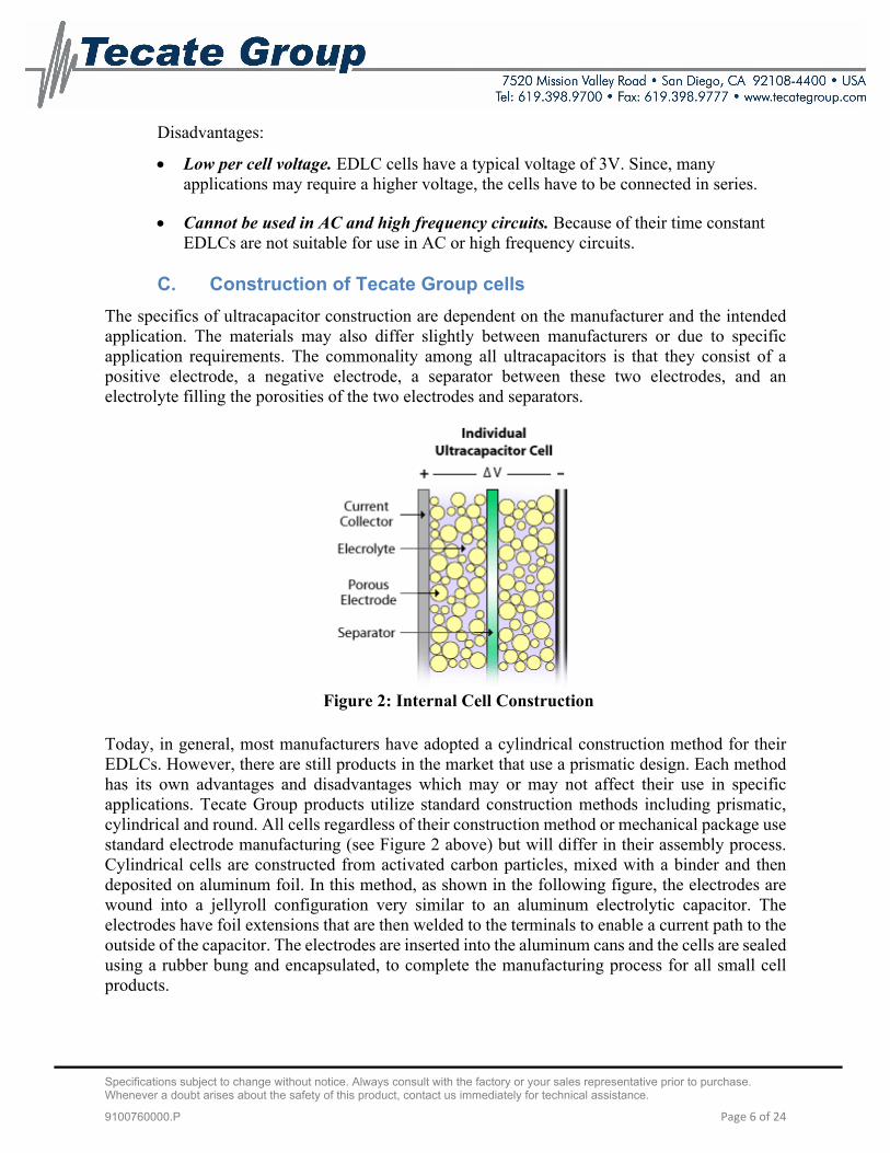
The specifics of ultracapacitor construction are dependent on the manufacturer and the intended application. The materials may also differ slightly between manufacturers or due to specific application requirements. The commonality among all ultracapacitors is that they consist of a positive electrode, a negative electrode, a separator between these two electrodes, and an electrolyte filling the porosities of the two electrodes and separators.
Figure 2: Internal Cell Construction
Today, in general, most manufacturers have adopted a cylindrical construction method for their EDLCs. However, there are still products in the market that use a prismatic design. Each method has its own advantages and disadvantages which may or may not affect their use in specific applications. Tecate Group products utilize standard construction methods including prismatic, cylindrical and round. All cells regardless of their construction method or mechanical package use standard electrode manufacturing (see Figure 2 above) but will differ in their assembly process. Cylindrical cells are constructed from activated carbon particles, mixed with a binder and then deposited on aluminum foil. In this method, as shown in the following figure, the electrodes are wound into a jellyroll configuration very similar to an aluminum electrolytic capacitor. The electrodes have foil extensions that are then welded to the terminals to enable a current path to the outside of the capacitor. The electrodes are inserted into the aluminum cans and the cells are sealed using a rubber bung and encapsulated, to complete the manufacturing process for all small cell products.

Specifications subject to change without notice. Always consult with the factory or your sales representative prior to purchase. Whenever a doubt arises about the safety of this product, contact us immediately for technical assistance.
9100760000.P Page 7 of 24
Figure 3: Cell Construction
D. Equivalent Circuit
EDLCs share the same equivalent circuit as conventional capacitors. The first order model is represented by the circuit below. It is comprised of four ideal components. The series resistance Rs is also referred to as the equivalent series resistance (ESR). This is the main contributor to power loss during charging and discharging of the capacitor. It is also comprised of a parallel resistance Rp which affects the self discharge, a capacitance C and a series inductor Ls that is normally very small as a result of the cell construction.
Figure 4: First Order Equivalent Circuit
Since Rp is always much larger than Rs it can be ignored. Also, because of the porous material used on the electrode of EDLCs, they exhibit non-ideal behavior which causes the capacitance and resistance to be distributed such that the electrical response mimics transmission line behavior. Therefore, it would be necessary to use a more general circuit, as shown in the figure 5, for representing the real electrical response.
Figure 5: Ladder Network

Specifications subject to change without notice. Always consult with the factory or your sales representative prior to purchase. Whenever a doubt arises about the safety of this product, contact us immediately for technical assistance.
9100760000.P Page 8 of 24
However, to simplify the circuit we can model the EDLC as an RC circuit. In this case the charge stored is Q=CV. The energy stored in the capacitor in Joules (watt-second) = 1/2CV2. Other useful formulas are discussed more in the sizing section.
III. Applications
Over the years EDLCs have found their way into many applications from consumer electronics to military and the automotive sector. They are used either as the primary energy source or to augment other energy devices. Some of the more common applications in use today include:
Figure 6: Application Breakout
As seen above EDLCs benefit many applications, from those involving short power pulses, to those requiring low-power support of critical memory systems. The cells can be used alone, or with other power sources. Battery life can be extended by freeing it from stressful high power tasks better suited to EDLC’s. For example in data storage there is a need for immediate and reliable power for short term bridge functions in order to protect and eliminate the risk of data loss. Ultracapacitors provide this next level up of reliability and do so with immediate power.
IV. Calculation of charge/discharge time
A. General Description
An ultracapacitor can be charged from any DC power source, DC power supply, battery or solar cell. There is no limitation in current and voltage within its maximum current and voltage rating as referred to in the specification sheet of each product. But one must ensure that the charging voltage does not exceed its rated voltage. The time required for the constant current and constant resistance charging/discharging are represented by equations (1) and (2) below:
Constant current discharge
t=C x (V0-V1)/ I (1)
Constant resistance discharge

Specifications subject to change without notice. Always consult with the factory or your sales representative prior to purchase. Whenever a doubt arises about the safety of this product, contact us immediately for technical assistance.
9100760000.P Page 9 of 24
t=-CxRxln(V1/V0) (2)
Where, t = charge/discharge time (s), V0 = initial voltage (v), V1 = final voltage after t(s) (v), I = constant current load (A) and R=constant resistive load (Ω).
The above equations may not always be accurate, as the internal resistance drop is not calculated with the above. Depending on the application this loss can be significant. For example in the constant current model the loss related to the equivalent series resistance (ESR) can be added as follows:
t= [C x (V0-V1) – (I x ESR)]/I (3)
B. Effect of Self Discharge
As with most electrochemical capacitors, the Tecate Group product does exhibit a self-discharge characteristic that is also related to the leakage current. This is the rate the capacitor will lose its energy without any load. In most applications this loss is negligible and can be ignored. This is based on the fact that most ultracapacitor applications require the part to be charged by a main source and only discharge for a short period of time (several seconds). During this short period there is not enough energy dissipated to affect your calculation. In longer term applications this leakage current will need to be added in to the equations above. More information can be obtained by contacting Tecate Group Engineering directly. [email protected]
V. Life Calculation
Although Ultracapacitors are known to have much longer lifetime than typical battery systems, their life is still limited. Unlike batteries ultracapacitors do not have a sharp end of life decline, but rather have a gradual degradation over its lifetime. The lifetime of an Ultracapacitor is greatly affected by ambient temperature, applied voltage and operating current. By reducing these factors as much as possible, ultracapacitor lifetime can be lengthened. Below we will review each point separately.
A. Temperature
The Ultracapacitor life is affected by the operating temperature. In general, lowering ambient temperature will increase the life of an ultracapacitor as typical life performance is impacted by voltage and temperature. Thus designing the ultracapacitors in locations where they are protected from extreme heat will greatly increase their useful life. It is not recommended to operate the cells above the maximum specified temperature. This will not only shorten capacitor life, but can also cause serious damage such as electrolyte leakage or rupture. Care should be taken, not only to look at the ambient temperature but also taking into consideration factors such as the radiation from heat generating elements inside the unit (power transistors, IC’s, resistors, etc.) and self-heating due to ripple current. Also, caution should be taken not to place heat-generating elements across from the capacitor on the opposite side of the PCB

Specifications subject to change without notice. Always consult with the factory or your sales representative prior to purchase. Whenever a doubt arises about the safety of this product, contact us immediately for technical assistance.
9100760000.P Page 10 of 24
B. Voltage
Operating voltage affects the useful life of an ultracapacitor similar to temperature, stated above. In general, lowering the operating voltage from the rated voltage will increase the life of an ultracapacitor. Care should be taken when designing the ultracapacitors in to circuits to not expose them to voltages above their rating. Check with Tecate Group engineering for further details and associated technical information.
C. Operating Current
One of the key attributes of an ultracapacitor is its low internal resistance and its ability to supply high power/currents. Although this is true, care needs to be taken when charging and discharging the capacitor with high currents. This high current can induce self-heating inside the capacitor which will increase its operating temperature rapidly. Sufficient cooling should be applied during high current high duty cycle applications.
VI. Specification
Tecate Group provides the latest data sheet and specification for each of its products on its website: https://www.tecategroup.com/ultracapacitors-supercapacitors/ultracapacitors.php Each data sheet provides a range of specifications which are described in more detail in the following section.
Specifications subject to change without notice. Always consult with the factory or your sales representative prior to purchase. Whenever a doubt arises about the safety of this product, contact us immediately for technical assistance.
9100760000.P Page 11 of 24
A. Specification Description
Capacitance – a measurement of energy storage in joules. C = QV
Voltage – the voltage provided in the specification is the maximum operating voltage for a single capacitor. The rated voltage is the voltage in which the performance data is measured. It is possible for the capacitors to experience voltages in excess of the rated voltage. The impact is dependent on the time and temperature during this exposure. At no time should the capacitor be subjected to voltages in excess of 10% of the rated voltage.
Equivalent Series Resistance (ESR), DC – the resistance corresponding to all the resistive components within the ultracapacitor, Rtot. This measurement is taken after 5 seconds. Since the time constant of the ultracapacitors is approximately 1 second, it takes approximately 5 time constants or 5 seconds to effectively remove 99.7% of the stored energy. Rtot is comprised of resistive components attributed to contact, electrode, electrolyte, and other material resistances.
Internal resistance, 100 Hz or 1 Hz – is a measure of the high frequency resistance component and is mainly attributed to contact resistance. Because of the time constant of the ultracapacitors, operation at this frequency is highly inefficient. This measurement is provided because it is simple to measure and correlates easily with the DC resistance.
Leakage Current – stable parasitic current expected when capacitor is held indefinitely on charge at the rated voltage. This value is voltage and temperature dependent. Data sheet measurement is at rated voltage and 25oC.
Operating Temperature Range – represents the operating temperature range of the ultracapacitor and may not reflect the ambient temperature.
Storage Temperature Range – represents the safe storage temperature without affecting ultracapacitor performance when no voltage is applied to the ultracapacitor.
Endurance, Capacitance – the maximum capacitance change expected if the ultracapacitor is held at rated voltage for the specified time and temperature which is intended to be the upper operational limits.
Endurance, Resistance – the maximum resistance change expected if the ultracapacitor is held at rated voltage for the specified time and temperature which is intended to be the upper operational limits.
Life Time – expected performance change for the ultracapacitor if held at rated voltage and 25oC for 10 years.
Life – expected performance change after cycling 500K times from rated voltage to half rated voltage. Cycling performed at a duty cycle resulting in no heating of the ultracapacitor with the ultracapacitor maintained at 25oC.

Specifications subject to change without notice. Always consult with the factory or your sales representative prior to purchase. Whenever a doubt arises about the safety of this product, contact us immediately for technical assistance.
9100760000.P Page 12 of 24
B. Measurement
The methods utilized for obtaining the data specified on the data sheets are outlined below. Alternative methods are possible but may achieve slightly different results.
1. Capacitance
Capacitance is measured during discharge of the ultracapacitor with a constant current source from its rated voltage to half its rated voltage. Referring to figure 7 and using the basic equation for average current in a capacitor:
)(T
VCI d
Solving for C:
)(
V
TIC d
where: Id=current (A) C=capacitance (F) ∆V=Vw-Vf (V) ∆T=td (s)
2. Resistance
Referring again to figure 7 the dc resistance, or ESR, is calculated from the following:
Id
VVfESR
min
The resistance measurement considers all resistive components over approximately five time constants of the product and is inclusive of all resistive elements. The actual resistance measured would be lower if measured over a shorter duration than the 5 seconds indicated.
Figure 7: Constant Current Testing Profile

Specifications subject to change without notice. Always consult with the factory or your sales representative prior to purchase. Whenever a doubt arises about the safety of this product, contact us immediately for technical assistance.
9100760000.P Page 13 of 24
3. Leakage Current
Due to the extremely large surface area of the electrode the time constant of the last 0.5% of the electrode area is extremely long due to the pore size and geometry. The longer the ultracapacitor is held on charge the lower the leakage current of the device. The reported leakage current is a measurement of the charging current after holding the device at rated voltage for 72 hours continuous at room temperature. The measured leakage current will be influenced by the temperature during the measurement, the voltage in which the device is measured and the age of the product.
VII. Performance Characteristics
The performance of ultracapacitors is affected by voltage and temperature. This section will describe the performance of the ultracapacitors under operating conditions such as temperature, dc life and cycling.
A. Temperature Effect on Initial Performance
One of the key attributes of ultracapacitors is its stability and performance over a wide temperature range. All of the Tecate Group products exhibit very similar behavior since they have similar chemistry and construction. In the figure below the capacitance and ESR behavior of the part is exhibited over the operating temperature range (-40°C to +65°C):
Figure 8: Performance over Operating Range
B. DC Life
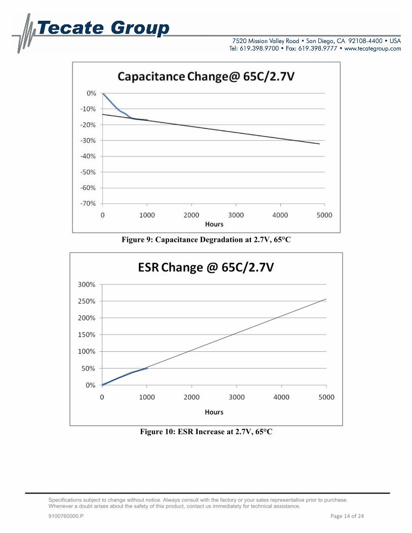
One type of application for ultracapacitors is for use as a backup energy source. In this type of application the cells are exposed to a set voltage for a long period of time and only discharge when needed. Below is a typical life graph for the Tecate Group cells:
Specifications subject to change without notice. Always consult with the factory or your sales representative prior to purchase. Whenever a doubt arises about the safety of this product, contact us immediately for technical assistance.
9100760000.P Page 14 of 24
Figure 9: Capacitance Degradation at 2.7V, 65°C
Figure 10: ESR Increase at 2.7V, 65°C

Specifications subject to change without notice. Always consult with the factory or your sales representative prior to purchase. Whenever a doubt arises about the safety of this product, contact us immediately for technical assistance.
9100760000.P Page 15 of 24
C. Cycling Life data
Another key attribute of ultracapacitors is their long cycle life capability. Cycle testing is performed on the products to determine the degradation of ultracapacitor performance over cycling events. The cycle testing is performed at ambient temperature with no forced convective cooling. The cycles are performed at a continuous current, as indicated on the data sheet, from the rated voltage to half rated voltage. A 15 second rest is allowed between each charge/discharge cycle.
Figure 11: Capacitance Change versus Cycles
D. Frequency Response
Ultracapacitors have a typical time constant of approximately one second. One time constant reflects the time necessary to charge a capacitor 63.2% of full charge or discharge to 36.8% of full charge. This relationship is illustrated in the following figure.
Figure 12: RC time constant relationship
Specifications subject to change without notice. Always consult with the factory or your sales representative prior to purchase. Whenever a doubt arises about the safety of this product, contact us immediately for technical assistance.
9100760000.P Page 16 of 24
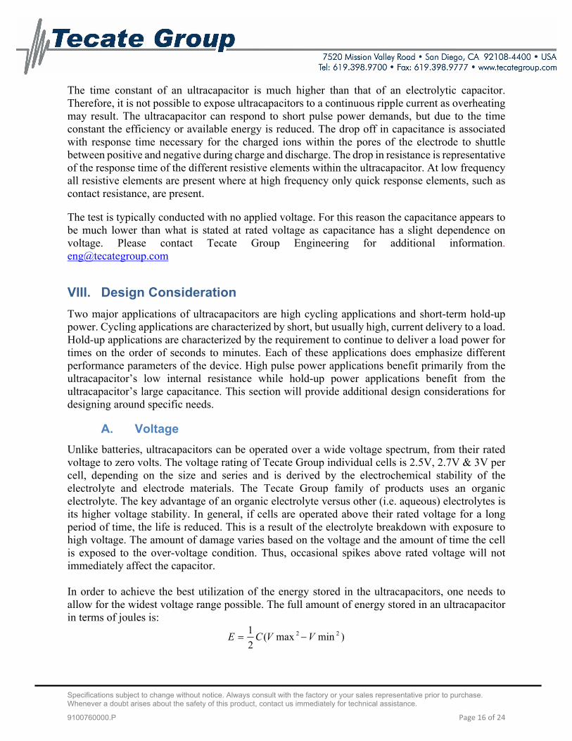
The time constant of an ultracapacitor is much higher than that of an electrolytic capacitor. Therefore, it is not possible to expose ultracapacitors to a continuous ripple current as overheating may result. The ultracapacitor can respond to short pulse power demands, but due to the time constant the efficiency or available energy is reduced. The drop off in capacitance is associated with response time necessary for the charged ions within the pores of the electrode to shuttle between positive and negative during charge and discharge. The drop in resistance is representative of the response time of the different resistive elements within the ultracapacitor. At low frequency all resistive elements are present where at high frequency only quick response elements, such as contact resistance, are present.
The test is typically conducted with no applied voltage. For this reason the capacitance appears to be much lower than what is stated at rated voltage as capacitance has a slight dependence on voltage. Please contact Tecate Group Engineering for additional information. [email protected]
VIII. Design Consideration
Two major applications of ultracapacitors are high cycling applications and short-term hold-up power. Cycling applications are characterized by short, but usually high, current delivery to a load. Hold-up applications are characterized by the requirement to continue to deliver a load power for times on the order of seconds to minutes. Each of these applications does emphasize different performance parameters of the device. High pulse power applications benefit primarily from the ultracapacitor’s low internal resistance while hold-up power applications benefit from the ultracapacitor’s large capacitance. This section will provide additional design considerations for designing around specific needs.
A. Voltage
Unlike batteries, ultracapacitors can be operated over a wide voltage spectrum, from their rated voltage to zero volts. The voltage rating of Tecate Group individual cells is 2.5V, 2.7V & 3V per cell, depending on the size and series and is derived by the electrochemical stability of the electrolyte and electrode materials. The Tecate Group family of products uses an organic electrolyte. The key advantage of an organic electrolyte versus other (i.e. aqueous) electrolytes is its higher voltage stability. In general, if cells are operated above their rated voltage for a long period of time, the life is reduced. This is a result of the electrolyte breakdown with exposure to high voltage. The amount of damage varies based on the voltage and the amount of time the cell is exposed to the over-voltage condition. Thus, occasional spikes above rated voltage will not immediately affect the capacitor. In order to achieve the best utilization of the energy stored in the ultracapacitors, one needs to allow for the widest voltage range possible. The full amount of energy stored in an ultracapacitor in terms of joules is:
)minmax(2
1 22 VVCE

Specifications subject to change without notice. Always consult with the factory or your sales representative prior to purchase. Whenever a doubt arises about the safety of this product, contact us immediately for technical assistance.
9100760000.P Page 17 of 24
Thus, the highest energy can be achieved if the capacitor is discharged to zero. Most electronics have a minimum voltage threshold which will limit the lower voltage which the capacitor can discharge. It is possible to utilize approximately 75% of the energy if the application allows the capacitor to discharge from rated voltage to ½ the rated voltage.
B. Ambient Temperature
Another key advantage of ultracapacitors is their wide temperature capability. The organic electrolyte has a low freezing point compared to the aqueous type enabling the cells to be used over a wider range of temperatures. Since the charge storage is not a chemical reaction, the capacitance is very stable over the entire operating temperature range of the capacitors. The capacitor resistance is affected by the ion mobility within electrolyte. So, as the temperature drops closer to the freezing point of the electrolyte, the ion mobility decreases resulting in higher resistance.
C. Life
Unlike batteries, ultracapacitors do not exhibit a true end of life. Its life is predominately affected by voltage and temperature. Typically, on data sheets, the end of life is determined with the capacitance dropping by 30% and the internal resistance (ESR) is doubling. Although in most applications the end of life will be when the performance of the ultracapacitors falls below the application requirements. This can be different from the data sheet specification. Therefore, each application needs to be evaluated separately based on its requirements and operating conditions in order to calculate its estimated life span.
The typical degradation behavior of the ultracapacitor resembles that of an exponential decay. The majority of the performance change occurs during the initial use of the ultracapacitor and this performance change then levels off over time. The most dramatic effect of the life degradation is on the internal resistance of the device.
D. Polarity
Tecate Group’s ultracapacitors are a symmetric device. Thus both the anode and cathode are made from the same material. If the positive and negative terminal and casing are also comprised of similar materials, then theoretically the ultracapacitor has no true polarity. For manufacturing and consistency purposes the terminals are marked with polarity. It is a recommended practice to maintain the polarity although catastrophic failure will not occur if the ultracapacitor is reversed charged for some reason. If the ultracapacitor has been conditioned for charge in a certain direction and then is changed, the life can be reduced due to this condition.
E. Charging
Ultracapacitors provide the unique capability to be charged and discharged at the same rate. This is possible since the energy that is stored, is not a result of a chemical reaction. Therefore, the rated current of the cells are both for charge and discharge. As far as the cell voltage and temperature are kept under the rated specification there is no real limit to the charge/discharge capability of the part.

Specifications subject to change without notice. Always consult with the factory or your sales representative prior to purchase. Whenever a doubt arises about the safety of this product, contact us immediately for technical assistance.
9100760000.P Page 18 of 24
F. Interconnection
For most applications a single cell at low voltage is not very useful and multiple cells are required to be placed in series. Since there is a tolerance difference between manufactured cells in capacitance, resistance and leakage current there will be an imbalance in the cell voltages of a series stack. It is important to ensure that the individual voltages of any single cell do not exceed its maximum recommended working voltage as this could result in electrolyte decomposition, gas generation, ESR increase and reduced life. This imbalance is initially dominated by the capacitance difference between the cells (i.e. a cell with a lower capacitance will charge to a higher voltage in a series string). For example, if two cells of 10F each are connected in series with one at +20% of nominal capacitance and the other at -10%, then the worst case voltage across the capacitors can be calculated by:
Vcap1=Vsupply x (Ccap1/(Ccap1 + Ccap2)
Assuming Vsupply=5.4V
Vcap1=5.4 x (12/(12+9)) = 3.08V
As can be seen, a proper cell balancing scheme needs to be placed within series connected cells to ensure no cell sees higher than rated voltage. Also, when the cells are on charge for a period of time the leakage current will dominate this difference (i.e. a cell with a higher leakage current will go to a lower voltage thus pushing the other cells in the string to a higher voltage). Proper cell balancing can eliminate this imbalance. There are two balancing schemes to tackle this problem, and ensure a properly balanced module. They are: Passive Balancing: One technique to compensate for variations in parallel resistance is to place a same valued bypass resistor in parallel with each cell, sized to dominate the total cell leakage current. This effectively reduces the variation of equivalent parallel resistance between the cells which is responsible for the leakage current. Passive voltage balancing is only recommended for applications that don’t regularly charge and discharge the ultracapacitors and that can tolerate the additional load current of the balancing resistors. It is suggested that the balancing resistors be selected to give additional current flow of at least 10 times the worst-case cell leakage current. Active Balancing: For applications with a limited energy source or high level of cycling an active voltage balancing circuit is preferred since it typically draws much lower current in steady state and only requires larger currents when the cell voltage is out of balance. The active circuit forces the voltage at the nodes of series connected cells to stay below a fixed reference voltage. In addition to ensuring accurate voltage balancing, active circuits typically draw much lower levels of current in steady state, and only require larger currents when the capacitor voltage goes out of

Specifications subject to change without notice. Always consult with the factory or your sales representative prior to purchase. Whenever a doubt arises about the safety of this product, contact us immediately for technical assistance.
9100760000.P Page 19 of 24
balance. These characteristics make active voltage balancing circuits ideal for applications that charge and discharge the cells frequently as well as those with a finite energy source.
G. Efficiency
Ultracapacitors, unlike batteries, have the same efficiency during charge or discharge. This contributes to one of the advantages of ultracapacitors which allows cells to be charged at a high current rate as long as the current is within the rated current for the device.
The only efficiency losses associated with ultracapacitors are due to internal resistance of the device resulting in IR drop during cycling. For most uses the ultracapacitor efficiency is in excess of 98%. For high current or power applications the efficiency is reduced. Typical efficiency under high current pulses is still greater than 90%.
H. Application Sizing
There are many unique applications for ultracapacitors. In general they can be categorized in two main areas: hold-up power and pulse power. Hold-up power is characterized by applications needing back-up power in the range of seconds to several minutes, whereas pulse power is characterized by high current short delivery to the load. For each application one has to look at different parameters of the cells. For example, in a hold-up application the importance is on the capacitance (C) of the cell whereas in a high power pulse application the internal resistance (ESR) becomes the limiting factor. In order to determine the right ultracapacitor size for an application a number of factors needs to be known. These include: maximum and minimum operating voltage of the application, the average current or power required, the operating environment temperature, the run time required and the operating life of the application. The first area to look at is the operating voltage. Ultracapacitor operating voltage is typically lower than the requirement for most applications, thus there will be a need to place several cells in series. In order to determine the number of cells needed we will use the formula:
# of cells in series(n) = Vr
V max Where:
Vmax is the maximum operating voltage Vr is the cell rated voltage
Now by knowing the average current needed in amps (I) and required run time in seconds (dT) and the minimum working voltage (Vmin), we can calculate and approximate capacitance need for the system using the formula:
min)max(
*
VV
dTICsys

Specifications subject to change without notice. Always consult with the factory or your sales representative prior to purchase. Whenever a doubt arises about the safety of this product, contact us immediately for technical assistance.
9100760000.P Page 20 of 24
The Csys is the system capacitance of the series connection of cells. As with any capacitor, when cells are placed in series the system capacitance is calculated by the formula:
CnCCCCsys
1
3
1
2
1
1
11
Since we are placing the same value capacitors in series the C1…Cn have the same value. Therefore:
n
CCsys or nCsysC *
This value can then be compared to our standard product offering to find the closest product for the application. In case the value of C is larger than any one product offering, then multiple cells can be placed parallel in order to achieve the desired rating. As with all capacitors, when you place cells in parallel their total capacitance is the sum of the individual capacitances. Therefore, take the calculated capacitance and divide by the capacitance available from the data sheet and round up to the next whole number. This will be the number of capacitors required in parallel. Other parameters to consider when sizing an application is the internal resistance of the part which induces a instantaneous voltage drop and the temperature, which on the low side increases the internal resistance and on the high side reduces the useful life. For all applications the minimum end of life requirements need to be considered to ensure proper initial sizing. To determine the ultracapacitor requirements for an application, four key parameters are required:
1. Working voltage, Vw, in Volts 2. Minimum voltage, Vmin in Volts 3. Average discharge current, I, in Amps or for the power worksheet the average discharge
power W in watts 4. Discharge time, t, in seconds
By simply entering these four parameters into the worksheet in the indicated areas the appropriate cells from our different series are displayed. For further information on sizing and cell selection please contact our technical department at 619-398-9700 or [email protected].
IX. Notes
A. Safety
Select ultracapacitor products have successfully passed UL810A testing and UL recognized components. All information can be found at the UL web-site under file number MH20839.

Specifications subject to change without notice. Always consult with the factory or your sales representative prior to purchase. Whenever a doubt arises about the safety of this product, contact us immediately for technical assistance.
9100760000.P Page 21 of 24
Individual capacitors are low voltage devices but are capable of delivering extremely high currents especially in short circuit situations. Handling of capacitors should be done in an uncharged state. When designing a system with higher voltages standard safety practices should be followed for the voltage levels of consideration. The packaging for the ultracapacitors is completely sealed. The devices do not contain re-sealable venting. Most devices contain a high pressure fuse enabling the packaging to open in a more controlled manner in the event of a catastrophic failure. Catastrophic failure for the ultracapacitors can occur in over voltage and over temperature situations. As the devices are operated in excess of the rated voltage, electrolyte decomposition will occur. The higher the current and temperature the more accelerated this decomposition will be. The typical failure sequence as the ultracapacitor is maintained well above its rated voltage with continued supplied current is a rise in the temperature of the device followed by an opening of the ultracapacitor package at the fuse. If product is found to be leaking (identified by a white salt crystal formation on product) the capacitor should be removed from the system. A leaking capacitor will eventually increase in resistance or could cause long term corrosion of interconnects. Incidental contact with the salt residue is not harmful although should not be ingested. Take normal precautions after contact which includes washing hands. In the event the packaging is compromised, either by puncturing or crushing, a very limited amount of electrolyte fluid will be released depending on the size of the ultracapacitor. An open or compromised package should be immediately removed from the system and placed in a well-ventilated area. The electrolyte has a high vapor pressure and quickly evaporates. The electrolyte is classified as flammable and should be handled with normal considerations for flammable materials.
Medical Life Support Policy: Tecate Group does not authorize the use of any of its products for use in life support devices or systems without the express written approval of an officer of the company. Life support systems are devices which support or sustain life, and whose failure to perform, when properly used in accordance with instructions for use provided in the labeling, can be reasonably expected to result in significant injury to the user.
B. Shipping
Based on UN3499 shipping regulations, effective January 1, 2013, all ultracapacitor cells and modules presently sold by Tecate Group are less than 10Wh capacity and comply with UN3499 regulations (including Special Provision 361 and 186) and meet all of the requirements when transported as individual capacitors or modules. Ultracapacitors with an energy storage capacity of 0.3Wh or less are not regulated and, therefore, are exempt from DG/HZM shipping regulations when transported as individual capacitors or modules. By meeting these requirements, all Tecate Group ultracapacitors and modules may be transported without DG/HZM restrictions, as detailed by these regulations.
C. Soldering & Mounting Recommendations
General guidelines:
Do not dip the entire ultracapacitor body into melted solder.

Specifications subject to change without notice. Always consult with the factory or your sales representative prior to purchase. Whenever a doubt arises about the safety of this product, contact us immediately for technical assistance.
9100760000.P Page 22 of 24
Only flux the leads of the ultracapacitor.
When soldering the capacitor on the wiring board, make sure the sleeving and body of the ultracapacitor does not touch any other component, with the exception of another ultracapacitor.
Excessive heat during soldering may cause the sleeve to shrink or crack and may also compromise the reliability of the cell. Do not exceed 70°C cell body temperature as this may damage the ultracapacitor.
The lead material is steel core, clad with Copper (30-45um depending upon the lead diameter) and plated with Tin (~11um).
Provide appropriate spaced holes to ensure proper mounting to the specified cell dimension in order to minimize the terminal leads from being mechanically stressed.
Use of a protective coating of components on the PCB is strongly recommended to mitigate potential risk of the components being damaged in an event of electrolyte leakage.
Board layout should take into account that the cell is not hermetic and during its lifetime electrolyte vapor and gases generated during normal operation may escape the package.
Hand Soldering
Warning: Do not touch the ultracapacitor external sleeve with the soldering iron which can cause the sleeve to melt or crack. The recommended temperature of the soldering iron tip is less than or equal to 350°C. The soldering duration should be shorter than 3 seconds. Minimize the time that the soldering iron is in direct contact with the terminals of the ultracapacitor as excessive heating of the leads may lead to higher equivalent series resistance (ESR).
Solder Composition and size - SAC 305: Sn96.5, Ag3.0, Cu0.5 alloy
Flux – Use a halide free, activated rosin based flux.
Maximum contact time with component leads – 10 seconds
NOTE: Do not exceed 70°C cell body temperature as this may damage the ultracapacitor.
Wave Soldering
Recommended Solder Pot Temperature – 248°C / 478°F
Solder Composition – SAC 305: Sn96.5, Ag3.0, Cu0.5 alloy
Recommended Fluxes – Water soluble flux, Kester 2331ZX or equivalent, or a Low Solids VOC-
free No-Clean flux comparable to Kester 979T

Specifications subject to change without notice. Always consult with the factory or your sales representative prior to purchase. Whenever a doubt arises about the safety of this product, contact us immediately for technical assistance.
9100760000.P Page 23 of 24
Recommended Preheat – Preheat board from bottom side only, bring top of board to 100C maximum immediately before soldering, preheat time will depend upon heating efficiency. Use a maximum preheating time of 60 seconds for PC boards 0.8 mm or thicker. Use the following table for wave soldering on leads only:
Solder Bath Temp. (°C) Recommended solder
Exposure (Sec) Maximum
Exposure (Sec)
220 7 9
240 7 9
250 5 7
260 5 5
NOTE: Do not exceed 70°C cell body temperature as this may damage the ultracapacitor.” Reflow Soldering Reflow soldering should not be used on the ultracapacitors. Circuit Board Cleaning
Circuit boards can be immersed or ultrasonically cleaned using suitable cleaning solvents for up to 5 minutes and up to 60° maximum temperatures. The boards should be thoroughly rinsed and dried. [Suitable cleaning solvents include] Pine Alpha ST-100S, Sunelec B-12, DK be clear CW-5790, Aqua Cleaner 210SEP, Cold Cleaner P3-375, Telpen Cleaner EC-7R, Clean-thru 750H, Clean-thru 750L, Clean-thru 710M, Techno Cleaner 219, Techno Care FRW-17, Techno Care FRW-1, Techno Care FRV-1, IPA (isopropyl alcohol), deionized water.] Consult with us if you are using a solvent other than any of those listed above. The use of ozone depleting cleaning agents is not recommended in the interest of protecting the environment.

Specifications subject to change without notice. Always consult with the factory or your sales representative prior to purchase. Whenever a doubt arises about the safety of this product, contact us immediately for technical assistance.
9100760000.P Page 24 of 24
D. Disposal
Ultracapacitors are neither specifically listed nor exempted from government hazardous waste regulations. The only material of possible concern is the organic solvent, which when discarded or disposed of, is a hazardous waste per Federal regulations (40 CRF 261). It is listed as Hazardous Waste Number U003, so listed due to its toxicity and ignitability. Disposal can occur only in properly permitted facilities. Check state and local regulations for any additional requirements, as these may be more restrictive than federal laws and regulations. It is the responsibility of the generator to determine at the time of disposal whether the product meets the criteria of a hazardous waste per regulations of the area in which the waste is generated and/or disposed of. Waste disposal must be in accordance with appropriate Federal, State, and local regulation. Shipment of wastes must be done with appropriately permitted and registered transporters.
E. Mechanical Impact on the Cells
Tecate Group products are constructed of a strength and weight optimized aluminum casing commonly referred to as the can. This can is pure aluminum and has the properties of pure aluminum. That is that the material is very malleable and can be formed without excessive force. Therefore, if the products are subjected to high mechanical impulse as in the case of dropping the cell from a substantial height, it is possible that the cell can be dented or otherwise deformed because of the impact. Any cell sustaining an impact should be examined thoroughly both physically and electrically to be certain there has been no deformation in the form of denting or creasing or showing the signs of negative effects on the electrical properties of the cell. If in doubt, the cell should not be used. The consequence of using a dented cell can be electrolyte leakage, short circuit, high leakage current or a combination of those effects among others. The best practice is to discard a damaged cell.
F. Shrink Sleeve
Each cell has a shrink sleeve covering the body of the cell. Even though the terminals of the cells are isolated from the body, the internal electrolyte of the cell is in contact with the body and carries some potential. Therefore, it is not recommended the shrink sleeve to be removed from the cells. It is necessary for safe implementation of the cells. Removal of the shrink sleeve is not a supplied configuration for any cell, thus the removal of the sleeve without prior consultation with Tecate Group will have warranty implications. The best practice is to discard a damaged cell