ultrascience net: network testbed for large-scale science applications
TRANSCRIPT

1
UltraScience Net: Network Testbedfor Large-Scale Science Applications
Nageswara S. V. Rao William R. Wing Steven M. Carter Qishi Wu
Abstract— UltraScienceNet is an experimental wide-area net-work testbed to enable the development of networking technolo-gies required for the next-generation large-scale scientific applica-tions. It provides on-demand, dedicated, high bandwidth channelsfor large data transfers, and also high resolution, high-precisionchannels for fine control operations. In the initial deployment,its data-plane consists of several thousand miles of dual 10 Gbpslambdas. The channels are provisioned on-demand using layer-1 and layer-2 switches in the backbone and multiple service pro-visioning platforms at the edges in a flexible configuration usinga secure control-plane. A centralized scheduler is employed tocompute the future channel allocations, and a signaling daemon isused to generate the configuration signals to switches at appropri-ate times. The control-plane is implemented using an out-of-bandvirtual private network, which encrypts the switching signals andalso provides authenticated user and application access. Transportexperiments are conducted on a smaller test connection which pro-vided us useful information about the basic properties and issuesof utilizing dedicated channels in applications.
Index Terms— Network testbed, dedicated channels, SONET,10GigE WAN-PHY, control-plane, data-plane, bandwidth sched-uler.
I. INTRODUCTION
The next generation of large-scale scientific applications in-volve expensive and powerful resources such as supercomput-ers, experimental facilities, and massive storage systems [4],[13]. Often these resources are created with a mission to sup-port the scientific community that may span across severalcountries, for example, Earth Simulator [7] or Spallation Neu-tron Source [17]. In these applications, the scientific progressmay depend on an adequate network access to these facilities tomove data across wide-area networks and also to steer computa-tions and experiments from remote sites. In fact, in some casesinadequate network connectivity – in terms of both bulk andstable bandwidths – may create resource bottlenecks, therebyfalling short of reaching the full potential of these valuable re-sources.
The high-performance networking requirements for theselarge-scale applications belong to two broad classes: (a) highbandwidths, typically multiples of 10Gbps, to support bulk datatransfers, and (b) stable bandwidths, typically at much lowerbandwidths such as 100s of Mbps, to support interactive, steer-ing and control operations. Currently, the Internet technologiesare severely limited in meeting these demands. First, such bulkbandwidths are available only in the backbone, typically sharedamong a number of connections that are unaware of the de-mands of others. Second, due to the shared nature of packet
The authors are with the Computer Science and Mathematics Division, OakRidge National Laboratory, Oak Ridge, TN 37831, [email protected]
switched networks, typical Internet connections often exhibitcomplicated dynamics, thereby lacking the stability needed forsteering and control operations [14]. In both cases, the prob-lem of transport becomes particularly difficult due to challengesin adapting TCP: it is extremely hard to sustain 10s of Gbpsthroughputs over wide-area links or to stabilize its dynamicseven at lower bandwidths.
It is generally believed that the above networking demandscan be effectively addressed by providing on-demand dedicatedchannels of the required bandwidths directly to end users or ap-plications. However, networks with such capabilities cannot bereadily deployed now using only the existing networking tech-nologies, for most of them have been developed for the Inter-net. Note that Internet is based on packet-switched paradigmwherein packets from various sources simultaneously share thenetwork, which is in stark contrast with the dedicated channelsthat share the network across time. Indeed, a number of diversecomponent technologies are needed to realize such a capabilityto support infrastructure, provisioning, transport, and applica-tion access. While technologies for infrastructure and applica-tion interfaces can be significantly leveraged from the existingones, certain provisioning and transport technologies requiresignificant development [5]. Furthermore, these technologiesmust be tested and demonstrated to be effective under realisticconnections since current simulations are limited for such spe-cial networks. Thus there is a need for a testbed that can provideadequate environments for developing these technologies withan objective of providing these capabilities on-demand to theend users or applications.
The UltraScience Net (USN) is commissioned by theU. S. Department of Energy (DOE) to facilitate the develop-ment of these constituent technologies specifically targeting thelarge-scale science applications carried out at national laborato-ries and collaborating institutions. Its main objective is to pro-vide developmental and testing environments for a wide spec-trum of the technologies that can lead to production-level de-ployments within the span of next few years. In fact, someportions of USN may be left in place or merged into produc-tion networks if they prove to be effective. There are a numberof testbeds such as UCLP [20], CHEETAH [2], and DRAGON[12] that provide dedicated channels. Compared to them, USNhas a much larger backbone bandwidth (20-40 Gbps) and largerfootprint (several thousands of miles), and a close proximity toseveral DOE facilities.
USN provides on-demand dedicated channels: (a) 10Gbpschannels for large data transfers, and (b) high-precision chan-nels for fine control operations. User sites can be connected toUSN through its edge switches, and can utilize the provisioned

2
dedicated channels during the allocated time slots. In terms oflayer-1 backbone connectivity, USN’s design and deploymentis similar to the Internet, but it’s control-plane is quite differ-ent mainly due to the ability of users and applications to setupand tear down channels on-demand. Its design required severalnew components including a Virtual Private Network (VPN) in-frastructure, a bandwidth and channel scheduler, and a dynamicsignaling daemon. In this paper, we briefly describe the designconsiderations and deployment details of these components.
In the initial deployment, its data-plane consists of dual 10Gbps lambdas, both OC192 SONET and 10GigE WAN PHY,of several thousand miles in length from Atlanta to Chicago toSeattle to Sunnyvale. The channels are provisioned on-demandusing layer-1 and layer-2 switches in the backbone and mul-tiple service provisioning platforms at the edges in a flexibleconfiguration using a secure control-plane. In addition, thereare dedicated hosts at the USN edges that can be used for test-ing middleware, protocols, and other software modules that arenot site specific.
The control-plane employs a centralized scheduler to com-pute the channel allocations and a signaling daemon to gener-ate configuration signals to switches. Due to access to usersand applications, the control-plane raised a number of securityissues that are not addressed in conventional IP networks. Thiscontrol plane is implemented using a hardware based VPN thatencrypts all signals on the control plane and also provides au-thenticated and authorized access.
The dedicated channels are quite appealing in addressing theabove network demands, but our current operational knowl-edge of utilizing them is quite limited, particularly for largebandwidth connections over long distances. While USN is be-ing rolled out, we conducted preliminary experiments to un-derstand the properties of dedicated channels using a smallerscale connection from Oak Ridge to Atlanta. Despite the lim-ited nature of this connection, several important performanceconsiderations have been revealed by these experiments. Wedescribe these results here due to their relevance in utilizingthe channels that will be provided by USN. Particularly, we de-scribe experimental results on large data transfers and stablecontrol streams over a dedicated 1Gbps channel of several hun-dred miles length implemented over ORNL-Atlanta productionOC192 link. The performance profile generated from trafficmeasurements on this channel indicates non-zero packet lossesand non-trivial jitter levels, both of which must be accountedfor by the transport protocols to ensure high throughput and ro-bust performance. We describe a UDP-based transport protocolby leveraging existing methods to achieve close to 100 percentchannel utilization for file and data transfers. We also tested anexisting protocol for implementing stable control streams overthis channel. These results provide valuable insights into boththe channel and host aspects of supporting data transfers overdedicated links.
This paper is organized as follows. In Section II, we describethe high-performance networking demands of large-scale sci-ence applications and the limitations of current infrastructuresand technologies in meeting them. The overall configurationand footprint of USN are described in Section III. The detailsof USN’s data-plane are described in Section IV. The basic
modes of utilizing USN’s data paths and hosts are described inSection V. The details about the control-plane are describedin Section VI. The transport experiment results on Oak Ridge-Atlanta connection are described in Section VII.
II. HIGH-PERFORMANCE NETWORKING
Supercomputers such as the new National Leadership ClassFacility (NLCF) and others being constructed for large-scalescientific computing will reach speeds approaching 100 ter-aflops within the next few years. They hold an enormouspromise for meeting the demands of highest priority projectsincluding climate modeling, combustion modeling, and fusionsimulation. They are also critical to other large-scale scienceprojects and programs, which span fields as diverse as earth sci-ence, high energy and nuclear physics, astrophysics, moleculardynamics, nanoscale materials science, and genomics. Theseapplications are expected to generate petabytes of data at thecomputing facilities, which must be transferred, visualized, an-alyzed by geographically distributed teams of scientists. Thecomputations themselves may have to be interactively moni-tored and actively steered by the scientist teams. In the areaof experimental science, there are several extremely valuableexperimental facilities, such as the Spallation Neutron Source,the Advanced Photon Source, and the Relativistic Heavy IonCollider. At these facilities, the ability to conduct experimentsremotely and then transfer the large measurement data sets forremote distributed analysis is critical to ensuring the produc-tivity of both the facilities and the scientific teams utilizingthem. Indeed, high-performance network capabilities add awhole new dimension to the usefulness of these computing andexperimental facilities by eliminating the “single location, sin-gle time zone” bottlenecks that currently plague these valuableresources.
Both classes of the above applications require next genera-tion network capabilities in terms of multiple 10Gbps channels,which are currently offered as single lambda services, namelyOC192 or 10GigE WAN PHY. For sub-lambda speeds of low-bandwidth low-jitter control channels, the requirements of bothusable bandwidth and precise control are extremely difficult tomeet over the current Internet. This is primarily due to theshared nature of these TCP/IP networks, which leads to unpre-dictable traffic levels and the complex transport dynamics. Byutilizing dedicated channels over switched circuits these diffi-culties can be almost, if not completely, eliminated.
The existing testbeds for exploring such high bandwidth orfine control channels typically have a very small footprint orbandwidth, and hence do not provide adequate developmentenvironments for the required high performance networkingtasks. In particular, they do not completely reflect the opera-tional effects of cross-country links operating at full capacity,which are critical to optimizing these protocols and applica-tions. Furthermore, these testbeds are not field hardened forhigh-performance production deployments and cyber defense.That is, they do not include multiple layers of redundant con-trol to deal with such real world events as the inevitable powerfailures and controlled recovery from them, or the need to de-fend against cyber attacks to subvert the control plane. USN
3
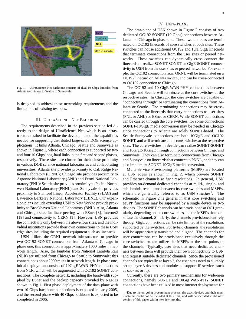
Fig. 1. UltraScience Net backbone consists of dual 10 Gbps lambdas fromAtlanta to Chicago to Seattle to Sunnyvale.
is designed to address these networking requirements and thelimitations of existing testbeds.
III. ULTRASCIENCE NET BACKBONE
The requirements described in the previous section led di-rectly to the design of UltraScience Net, which is an infras-tructure testbed to facilitate the development of the capabilitiesneeded for supporting distributed large-scale DOE science ap-plications. It links Atlanta, Chicago, Seattle and Sunnyvale asshown in Figure 1, where each connection is supported by twoand four 10 Gbps long-haul links in the first and second phases,respectively. These sites are chosen for their close proximityto various DOE science national laboratories and collaboratinguniversities. Atlanta site provides proximity to Oak Ridge Na-tional Laboratory (ORNL); Chicago site provides proximity toArgonne National Laboratory (ANL) and Fermi National Lab-oratory (FNL); Seattle site provides proximity to Pacific North-west National Laboratory (PNNL); and Sunnyvale site providesproximity to Stanford Linear Accelerator Facility (SLAC) andLawrence Berkeley National Laboratory (LBNL). Our expan-sion plans include extending USN to New York to provide prox-imity to Brookhaven National Laboratory (BNL). Also, Atlantaand Chicago sites facilitate peering with ESnet [8], Internet2[18] and connectivity to CERN [1]. However, USN providesthe connectivity only between the above four sites, and the indi-vidual institutions provide their own connections to these USNedge sites including the required equipment such as linecards.
USN utilizes the ORNL network infrastructure to providetwo OC192 SONET connections from Atlanta to Chicago inphase one; this connection is approximately 1000 miles in net-work length. Also, the lambdas from National Lambda Rail(NLR) are utilized from Chicago to Seattle to Sunnyvale; thisconnection is about 2000 miles in network length. In phase one,initial deployment consists of 10GigE WAN-PHY connectionsfrom NLR, which will be augmented with OC192 SONET con-nections. The complete network, including the bandwidth sup-plied by ESnet and the backup capacity provided by NLR isshown in Fig 1. First phase deployment of the data-plane withtwo 10 Gbps backbone connections is expected in early 2005,and the second phase with 40 Gbps backbone is expected to becompleted in 2006.
IV. DATA-PLANE
The data-plane of USN shown in Figure 2 consists of twodedicated OC192 SONET (10 Gbps) connections between At-lanta and Chicago in phase one. These two lambdas are termi-nated on OC192 linecards of core switches at both sites. Theseswitches can house additional OC192 and 10/1 GigE linecardsthat terminate connections from the user sites or peered net-works. These switches can dynamically cross connect thelinecards to realize SONET-SONET or GigE-SONET connec-tivity to USN from the user sites or peered networks. For exam-ple, the OC192 connection from ORNL will be terminated on aOC192 linecard on Atlanta switch, and can be cross-connectedto OC192 connection to Chicago.
The OC192 and 10 GigE WAN-PHY connections betweenChicago and Seattle will terminate at the core switches at therespective sites. In Chicago, the core switches are capable of“connecting through” or terminating the connections from At-lanta or Seattle. The terminating connections may be cross-connected to the linecards that carry connections to user sites(FNL or ANL) or ESnet or CERN. While SONET connectionscan be carried through the core switches, for some connectionsSONET-10GigE media conversion may be needed in Chicagosince connections to Atlanta are solely SONET-based. TheSeattle-Sunnyvale connections are both 10GigE and OC192SONET, and will terminate at the core switches at the respectivesites. The core switches in Seattle can realize SONET-SONETand 10GigE-10GigE through connections between Chicago andSunnyvale. They can also terminate connections from Chicagoand Sunnyvale on linecards that connect to PNNL, and they canalso implement SONET-10GigE media conversion.
Multi Service Provisioning platforms (MSPP) are locatedat USN edges as shown in Fig. 2, which provide SONETand Ethernet channels at finer resolutions. In general, USNprovides on-demand dedicated channels at multi-, single- andsub-lambda resolutions between its core switches and MSPPs,which are generically referred to as USN switches1. Theschematic in Figure 2 is generic in that core switching andMSPP functions may be supported by a single device or twodevices. The SONET channels can be provisioned at OC1 gran-ularity depending on the core switches and the MSPPs that con-stitute the channel. Similarly, the channels provisioned entirelythrough GigE connections can be rate limited at the resolutionssupported by the switches. For hybrid channels, the resolutionswill be appropriately translated and aligned. The channels foruser connections can be provisioned exclusively through thecore switches or can utilize the MSPPs at the end points ofthe channels. Typically, user sites that need dedicated chan-nels between them will provide their own connectivity to USNand request suitable dedicated channels. Since the provisionedchannels are typically at layer-2, the user sites need to suitablyset up layer-3 devices and modules to support IP services suchas sockets or ftp.
Currently, there are two primary mechanisms for wide-areaconnections, namely SONET and 10Gig WAN-PHY. SONETconnections have been utilized in most Internet deployments for
1Due to the on-going procurement process, the exact devices and their man-ufacturers could not be included at this time, and will be included in the nextversion of this paper within next few months.

4
switches
switches switches
switchescore
corecore
core
MSPP MSPP
MSPP
host
host
host
Atlanta
ChicagoSeattle
Sunnyvale
GigE LAN
OC192 or 10GigE
Fig. 2. Data Plane of UltraScienceNet consists of core switches and MSPPs.
the past several years, and are considered fairly mature technol-ogy. 10GigE WAN-PHY is a relatively new technology, but isquite promising in part due to lower cost of deployment. Onthe other hand, its performance over wide area connections isnot completely well-understood. By utilizing both technolo-gies for long-haul connections, USN provides an infrastruc-ture where they can be studied in-depth by carefully designedexperiments particularly in terms of the performance they de-liver to the large-scale science applications. In particular, spe-cific to dedicated control channels of finer resolutions, thesetwo technologies must be analyzed in detail. At the surface,SONET multiplexing seems to provide more stable bandwidthparticularly at sub-lambda resolutions due to its time-divisionmultiplexing and strict reshaping. On the other hand, 10GigEconnections can be rate limited at the switches to realize sub-lambda rates, but lack of strict time-division multiplexing hasa potential for introducing higher levels of jitter. It is an openissue as to whether such jitter levels will negatively impact theapplication performance, and these issues can be investigatedusing USN channels.
USN also provides Linux hosts connected to MSPPs asshown in Figure 2 to provide environments to support the devel-opment and testing of protocols, middle ware, and applications.Users can be given accounts on USN hosts so that software canbe downloaded onto them, and development and testing can becarried out by setting up appropriate channels on USN data-plane. In this mode, user can have access to the dedicated chan-nels of various resolutions at distances ranging from few hun-dred miles (from user sites to USN) to thousands of miles (onUSN data-plane), and the testing can be carried out in a siteneutral manner.
V. USER AND APPLICATION SUPPORT
UltraScience Net is based on the concept of giving usersand applications a direct access to layer-1 light paths with zeropacket re-ordering, zero jitter, and zero congestion. In addition,
switchescorecore
switcheshost NICChannel
USNNIC host
(a)
USN
host hostNIC NIC
VLAN tagged channels
core
switches
core
switchesChannels
(b)
USN
host hostNIC NIC
VLAN tagged channels
core
switches switchesChannel
coreEthernetswitch
Ethernetswitch
(c)
Fig. 3. Connecting hosts to USN channels: (a) NICs directly connected to coreswitches, (b) VLAN tagging to utilize multiple USN channels, and (c) VLANtagging to share single USN channels.
it also provides dedicated level-2 paths with low re-orderingrate, low jitter and no congestion. In this sense, it is an im-plementation of the research network described in the DOERoadmap Workshop document [6]. Its underlying networkingtechnologies are guided by the DOE workshop on provision-ing and transport areas [5]. Users can provision USN dedi-cated channels through a bandwidth scheduler as needed bytheir tasks. The channels might be utilized for tasks as varied asfile transfers, computations scheduled on supercomputers, test-ing new protocols or middleware, or developing techniques forremote visualization. User sites connect their hosts or subnetsto USN channels through their own specialized connections tocore switches or MSPPs. They may need to support the under-lying layer-3 capability if IP services need to be executed trans-parently. In the simplest case, GigE Network Interface Cards(NICs) of two hosts may be connected to the end-points of adedicated USN channels as shown in Figure 3(a). Then IP con-nectivity between the two hosts may be ensured simply by for-warding the destination packets to the NICs and appropriatelymaking the arp entries. By utilizing Ethernet switches that areVLAN-enabled it is possible to utilize multiple USN channelsas in Figure 3(b), and also realize multiple subchannels over asingle USN channel by VLAN tagging as in 3(c).
On the other hand, when subnets are connected to the endpoints of a USN channel, the connected routers must be suitablyconfigured to appropriately forward the IP packets as shownin Figure 4. Once such layer-3 configurations are made, var-ious types of protocols, middleware and application modulescan make use of the provisioned dedicated circuits. However,

5
USN
host hostNIC NIC
core
switches
core
switchesChannels
subnet: layer−3 subnet: layer−3
router router
Fig. 4. Connecting subnet to USN channels.
strict USN cyber policies and guidelines are to be followed bythe user sites before they are allowed to connect to USN andrequest channels. Users can utilize hosts located at USN edgesas regular users to test protocols, middleware and other appli-cation level technology. In this mode, users will be providedaccounts on the hosts and to the scheduler that will enable themto setup channels between the hosts.
VI. CONTROL-PLANE
A control-plane is needed for facilitating a number of USNfunctions:(a) monitoring, configuration and recovery of its core
switches, MSPPs, and hosts,(b) providing user access to USN hosts, and user/application
access for requesting channel setup and obtaining state in-formation about hosts and channels,
(c) signaling for on-demand setting-up and tearing down ofthe dedicated channels, and
(d) facilitating peering with other networks, particularly thosethat support user/application controlled paths.
In conventional IP networks, a control-plane is employed forthe function (a), which is typically implemented out-of-bandusing proprietary vendor technologies. Such a control-planeprovides access only to network operators and typically sup-ports (infrequent) manual configuration of various switches androuters, all of which are typically produced by the same vendor.The functions (b)-(d) above distinguish USN from the currentproduction IP networks to a large extent.
USN accepts user requests for scheduling dedicated chan-nels in future time-slots and grants them based on the band-width availability and feasibility constraints. This task involvesscheduling the bandwidth on various connections to composethe requested channel, and also deriving the cross-connectionsat the core switches and MSPPs. Various allocations and cross-connection information is stored on a central server located atORNL. A signaling daemon on this server constantly moni-tors the allocations and sends configuration signals to the con-stituent switches to setup and tear down the channels. The abil-ity of the applications to actively access the control plane ofUSN has posed unique challenges that are not faced by the In-ternet and also not directly addressed by existing methods. Re-call that the end-points of data-plane are connected to user sites
switches
switches switches
switchescore
corecore
core
MSPP
MSPP
host
host
Atlanta
ChicagoSeattle
Sunnyvale
Encrypted and authorized VPN channels
local connections
MSPP
host Oak Ridge
signalling
VPN
VPN
VPN
VPN
scheduling
VPNauthentiication
Fig. 5. Control-plane supported on VPN.
as per USN cyber security guidelines, and the data channelsare accessed by only such “physically” connected sites. On theother hand, users that request the channels must be able to ac-cess the control-plane to acquire information needed to gener-ate the channel requests. Such users/applications can be locatedanywhere on the Internet. The ability to affect the channels andswitch configurations potentially opens the whole infrastructureto cyber attacks. For example, if sent in the clear such requestscan be sniffed and crafted requests can be injected to hijack thecontrol streams. Furthermore once hijacked, the recovery canbe prevented through denial-of-service attacks on the control-plane. Thus, users and applications must be appropriately au-thenticated and authorized before their requests can be granted,and in addition, all traffic between users and control-plane mustbe encrypted.
In terms of the signaling, the switches accept TL1 or GMPLS(Generalized Multiple Protocol Label Switching) commands tosetup and tear down the channels and realize cross connectionson demand. USN switches accept only clear text TL1 or GM-PLS commands through their management interfaces, whichcan be easily sniffed and crafted packets can be injected by anyone having access to their ports. Most of these devices do notsupport IPSec or ssh services because traditionally these inter-faces are accessible only through a proprietary control-planewith access only to network operators. Thus, the configurationand other commands from the central signaling daemon need tobe encrypted so that they cannot be sniffed or altered; further-more, access to these signaling paths must be protected againstthe injection of crafted packets. Thus, the control-plane mustallow only the authenticated and authorized entities to send andreceive the signaling messages.
The control-plane operations are coordinated by a centralizedsystem located at ORNL that: (a) maintains the state of band-width allocations on each link, and also the cross-connectionconfiguration information for each core switch and MSPP; (b)accepts and grants requests for current and future channels to
6
applications by suitably composing the segments with requiredbandwidths; and (c) sends signaling messages to switches asrequired by the schedule for setting up and tearing down thededicated channels. The control-plane is supported by a num-ber of hardware VPN units, which securely relay the TL1 sig-nals to the respective switches from the signaling daemon. Thisscheme facilitates the immediate deployment using interfacescurrently available across all USN switches.
A. VPN Implementation
We have designed a control-plane using a VPN shown in Fig-ure 5, which serves the purposes listed in (a)-(d) above. TheVPN is implemented in hardware using a main unit (NetscreenNS-50) at ORNL and secondary units (Netscreen NS-5) at eachof the remote sites. A VPN tunnel is configured between themain unit and each of the secondary units so that only authen-ticated and authorized traffic is allowed on each of the tunnels,and the traffic is encrypted using IPSec. Each VPN tunnel car-ries three types of encrypted traffic flows: (i) user access tohosts, (ii) management access to hosts and switches, and (iii)the signaling messages to switches. The users are provided au-thenticated access to the VPN through the main unit, and in ad-dition hosts require ssh logins. The management host at ORNLis authenticated and located in the secure domain of NS-50 sothat monitoring and related traffic is secured. The signalingserver is also located within the secure domain of NS-50 sothat the signaling messages are secured via the VPN tunnels.This scheme protects using IPsec all the three types of trafficagainst sniffing and altering of packets, and also prevents theinjection of crafted attack packets by third parties through theaccess control at NS-50. The channel requests are handled by asecure https server located on the ORNL server, which itself islocated within the secure domain of NS-50. Users are authenti-cated and authorized to access the https server through NS-50.
B. Bandwidth Scheduler
We now briefly describe the bandwidth scheduler that allo-cates the channels to various requests. Note that MPLS andGMPLS technologies only provide mechanisms to set up chan-nels at the time of request using OSPF-TE and RSVP-TE, re-spectively. Neither would allow setting up channels in futuretime-slots. Our scheduler to facilitate future allocations is basedon our previous work on the quickest path problems under time-varying bandwidths [10].
The scheduler can be used to check the availability of a chan-nel of specified bandwidth b between two ports located on coreswitches or MSPPs during a time-slot of duration t in future.It can also list all time-slots during which such channel withbandwidth b is available for duration t. USN is represented asgraph G = (V, E) where each node represents a core switch orMSPP, and each edge represents a connection such as OC192 or10GigE WAN-PHY. Parallel edges are allowed to reflect mul-tiple connections, and each node v ∈ V is provided the infor-mation about which of its edges can be composed to form achannel. For each edge e ∈ E, we store a list Re of bandwidthreservations as a piecewise constant function of time. We now
outline the all-slots version of the scheduler that lists all avail-able time-slots for a channel of bandwidth b from port ps ofnode s to port pd of node d. For each e ∈ E, we generate alist Le of non-disjoint intervals such that bandwidth b is avail-able on e for duration t starting any time within any interval.The algorithm is essentially the well-known all-pairs shortestpath algorithm [3] with the modification to utilize the lists Le’sin the computation. Let the nodes be denoted by 1, 2, . . . n, andLk[i, j] denote the sequence of disjoint intervals listing all start-ing points of a channel of bandwidth b and duration t from theappropriate ports of nodes i to j only through nodes 1, 2, . . . k.Thus Ln[s, d] lists all slots during which the required channelof bandwidth b and duration t is available. The outline of thealgorithm is as follows; for simplicity we skip the initializationand the details corresponding to cross-connection informationat the nodes.
algorithm ALL-SLOTS;1. for k = 1, 2, . . . , n do2. for i = 1, 2, . . . , n do3. for j = 1, 2, . . . , n do4. Lk[i, j]← Lk−1[i, j]
⊕{
Lk−1[i, k]⊗
Lk−1[k, j]}
;5. return(Ln[s, d]);
In the above algorithm the operation⊕
corresponds to merg-ing the intervals of the corresponding lists, and the operation
⊗
corresponds to computing the intervals obtained by composingthe channels from i to k and k to j to form single channels fromi to j. The complexity of this algorithm is polynomial in n. Thisalgorithm is based on a special structure within the well-knownclosed semi-ring framework for shortest path problems [3]. Inparticular, the closed semi-ring of ALL-SLOTS is defined oninfinite sequences of disjoint intervals, where
⊕
and⊗
corre-spond to the summary and extension operations, respectively.
The scheduler has also presented interesting problems froma strategic point of view. Clearly, it would be a mistake to de-sign a rigid scheduler that observed strict wall-clock bounds onwhen circuits were set up or torn down. For example, usersmay not know precisely when a job on a supercomputer willexit and make data available for transport. In addition, evenknown-size data sets may have unpredictable load times sincethe data is typically spread across multiple disks in a parallel filesystem and load times will vary from run to run. Furthermore,in steered computations, it is not always possible to know therun times in advance since the parameters may be specified onthe fly. To accommodate these scenarios, one approach beingconsidered for the scheduler is to allow the user to specify, notan absolute start and stop time for channels, but instead a win-dow within which the transfer must be completed. Also, sparecapacity on the links will be used to accommodate jobs that runbeyond their allocated time slots.
VII. EXPERIMENTS WITH DEDICATED CHANNELS
To optimally utilize dedicated channels provisioned by USNit is important to understand the channel properties and their in-teractions with the hosts, including NIC, kernel and application

7
aspects. Our current experience of network protocols is mostlylimited to the Internet environments. For dedicated channelsin particular, the application-level experimental results are lim-ited to testbeds with limited capacities and/or distances. As apreparatory phase for USN we set up a testbed with a dedicated1Gbps channel between two hosts located at ORNL via an IPchannel that loops back over ORNL-Atlanta OC192 link. Ourobjective is to perform experiments to understand the propertiesof dedicated channels as well as hosts for supporting data trans-fers at the rate of 1Gbps and stable control streams at signifi-cantly smaller bandwidths. Due to the scarcity of experimentalresults over realistic dedicated channels, our results provide astepping stone for developing the technologies for USN chan-nels (a more detailed account of these results can be found in[15]).
While the dedicated channels obviate the need for conges-tion control, there are a number of important issues that criti-cally affect the network performance observed at the applica-tion level:(a) Capacity and Throughputs: In general, the application
level throughputs are smaller than the channel capacitiesdue to channel and host losses, which in turn are a functionof sending rates at the source. Consequently, it is sub-optimal to a priori fix the source sending rate right at thechannel capacity; instead, it must be maintained at a levelto ensure the highest goodput at the destination.
(b) Host Issues: In addition to the link properties, a num-ber of host components play a critical role in deciding theachieved throughputs or jitter levels, and their effects be-come particularly important at 1-10Gbps data rates. Be-cause IP packets from the source application are copiedinto kernel buffers and then onto NIC, various buffer sizestogether with the speeds and policies for clearing them canhave an impact on the source rates and dynamics. The dif-ferences in the rates of NIC and provisioned channels canresult in losses since most Ethernet cards do not supportexplicit rate controls. Consequently, the packets may ex-perience losses or jitter, both of which could appear ran-dom to the sender or receiver.
(c) Jitter and Stabilization: When control operations are tobe performed over network connections, it is very impor-tant that the packets flows be stable. Variations in delays,namely jitter, can destabilize transport flows and cause theloss of control. The lost packets have to be re-sent therebyincreasing their net delays and contributing to jitter. Whilethe losses over dedicated links are much less pronouncedthan over Internet, they still need to be explicitly accountedfor in designing protocols for stable streams.
Effects of the above factors on applications and protocols canbe assessed by conducting experiments over dedicated chan-nels, which is a main focus of this section. We tested a numberof existing protocols for high-throughput data transfers, includ-ing SABUL, tsunami, and UDT. In particular, a file transferprotocol was proposed in [15] with adjustable rate control pa-rameters, which were manually tuned to achieve 990Mbps filetransfer rates. We describe in this section results based on theseprotocols and also the protocol of [16] for implementing stablecontrol flows.
ORNL
Juniper M160
router
Juniper M160
RouterAtlanta
GigE link
GigE link
ORNL hostUnet1
LinuxDual Xeon
ORNL hostUnet2
LinuxDual Opteron
ORNL
250 miles
OC192
Fig. 6. ORNL-Atlanta-ORNL dedicated 1 Gbps IP connection.
OC192
Juniper M160ORNL router
Atlanta RouterJuniper M160
over SONET1Gbps IP streams
IP loopback
forwardingFilter based
from unet2GigE link
from unet1GigE link
Fig. 7. Router configuration for implementing dedicated channel
A. Channel Provisioning
Our testbed consists of two hosts, called unet1 and unet2,both located at ORNL. Each of them is equipped with a dedi-cated NIC which is connected to a GigE slot on a linecard ofJuniper M160 router located at ORNL as shown in Figure 6.There is an OC192 link from this ORNL router to another Ju-niper M160 router located in Atlanta, which is approximately250 miles away. Only 1 Gbps of ORNL production traffic iscurrently carried on this OC192 link, and thus there is a sparebandwidth of 9 Gbps on this link. We utilize 2 Gbps of thisspare bandwidth to implement a loop-back connection fromORNL to Atlanta back to ORNL. The traffic at each of the hostsis limited to 1Gbps due to the Ethernet connection. And thetraffic flows from the hosts will flow unimpeded between therouters at ORNL and in Atlanta over the OC192 link. This ar-rangement effectively realizes a dedicated 1Gbps IP connectionbetween unet1 and unet2 of approximately 500 miles in length.
Both unet1 and unet2 NICs have IP addresses belonging to alocal subnet, and thus by default the IP packets between themare forwarded within the GigE linecard of the router itself. Wechanged this default routing so that the IP packets from eachof these ports are statically forwarded to the output port of theOC192 linecard by utilizing the Filter Based Forwarding (FBF)capability of ORNL router. This is achieved by applying a fire-wall filter to each GigE port to incorporate a routing-instancethat specifies the static route for all arriving packets to departvia the OC192 linecard.
The IP packets arriving at Atlanta router are handled by the

8
Fig. 8. Measurements for ORNL-Atlanta-ORNL dedicated 1Gbps IP channel.Each point in horizontal plane represents sending rate given by window size andidle time pair. Top plot corresponds to sending rate, middle plot corresponds tothe goodput at the destination and the bottom plot corresponds to the loss rate.
default routes, namely, the packets from a ORNL host des-tined to other ORNL hosts are simply routed back at the OC192linecard. Under this configuration, packets between unet1 andunet2 are routed along the loop-back path implemented overOC192 link as shown in Figure 7. While this configuration pro-vides a dedicated 1Gbps channel between unet1 and unet2, itis not a lightpath or an MPLS tunnel in a strict sense. The un-derlying mechanism of this channel provisioning makes it moresimilar to an MPLS tunnel than a lightpath. On the other hand,when viewed from an end-host viewpoint, this configuration isquite similar to how typical PC hosts might be connected toutilize a dedicated USN SONET channel (lightpath), namelythrough an Ethernet interface as described in Section V.
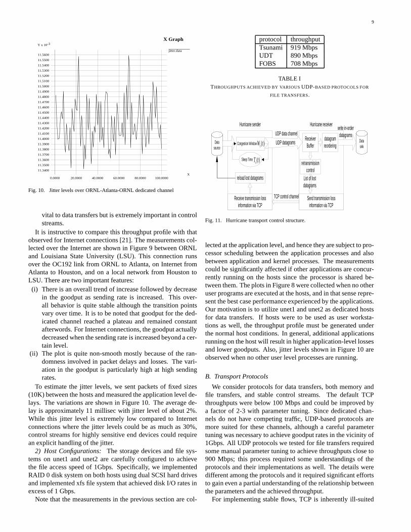
1) Channel Characteristics: Using a UDP stream withvarying sending rates we measured the effective throughput,called the goodput, at the destination, and also the loss rate.The sending rate is controlled by transmitting a number of data-grams, denoted by the window size Wc(t), in a single burst andthen waiting for a time period called the sleep time Ts(t). Thusthe sending rate is specified by a point in the horizontal plane,given by (Wc(t), Ts(t)), and its corresponding sending rate isshown in the top plot of Figure 8. The goodput measurementsat the destination corresponding to various window size andsleep (idle) time pairs are shown in the middle plot, which iscommonly known as the throughput profile. When the sending
020 40 60 80
100
020
4060
80100
0
5
10
cwin (datagrams of size 1472 bytes)
Goodput vs. cwin & idle time (Mon Dec 02 20:37:04 2002)
idle time (miliseconds)
go
od
pu
t (M
bp
s)
020 40 60 80
100
020
4060
80100
0
50
100
cwin (datagrams of size 1472 bytes)
Loss rate vs. cwin & idle time (Mon Dec 02 20:37:04 2002)
idle time (miliseconds)
loss r
ate
(%
)
Fig. 9. Measurements for ORNL-LSU Internet Connection. Each point inhorizontal plane represents a sending rate given by window size and idle timepair. Top plot corresponds to the goodput at the destination and the bottom plotcorresponds to the loss rate.
rate is small, the destination goodput increases with the send-ing rate, and reaches a plateau within the vicinity of 1Gbps asshown in the right hand side of the throughput profile. In thebottom plot, the loss rate is shown as a function of the windowsize and idle time. The loss rates are near zero when the send-ing rate is low, but they becomes significant when the sendingrate reaches the vicinity of 1Gbps, where they monotonicallyincrease with the sending rate. We also observed that the lossrates from multiple runs of an experiment with the same send-ing rate vary within a certain range even though the averagetrend was monotonic as shown in Figure 8.
Based on the measurements, one can draw two important ob-servations:(a) For throughputs around the vicinity of 1 Gbps, suitable
sending rate must be computed to achieve goodput plateauwith minimal loss rate. From a transport perspective, thelost packets have to be identified and re-sent, and this isa process which consumes CPU resources, particularly soat high throughput rates. It is important to minimize thisoverhead activity to optimize the throughput, and this inturn involves utilizing a sending rate at a minimal lossrate. On the other hand, extremely low loss rates can onlybe achieved when the goodputs are significantly below 1Gbps.
(b) At all high sending rates, the losses are non-zero and ran-dom. Hence flow stabilization at these fixed target band-widths requires explicit step size adaptation to achieveoverall flow stability [16]. This stability is not particularly
9
X Graph
jitter.data
Y x 10-3
X11.3400
11.3500
11.3600
11.3700
11.3800
11.3900
11.4000
11.4100
11.4200
11.4300
11.4400
11.4500
11.4600
11.4700
11.4800
11.4900
11.5000
11.5100
11.5200
11.5300
11.5400
11.5500
11.5600
0.0000 20.0000 40.0000 60.0000 80.0000 100.0000
Fig. 10. Jitter levels over ORNL-Atlanta-ORNL dedicated channel
vital to data transfers but is extremely important in controlstreams.
It is instructive to compare this throughput profile with thatobserved for Internet connections [21]. The measurements col-lected over the Internet are shown in Figure 9 between ORNLand Louisiana State University (LSU). This connection runsover the OC192 link from ORNL to Atlanta, on Internet fromAtlanta to Houston, and on a local network from Houston toLSU. There are two important features:(i) There is an overall trend of increase followed by decrease
in the goodput as sending rate is increased. This over-all behavior is quite stable although the transition pointsvary over time. It is to be noted that goodput for the ded-icated channel reached a plateau and remained constantafterwords. For Internet connections, the goodput actuallydecreased when the sending rate is increased beyond a cer-tain level.
(ii) The plot is quite non-smooth mostly because of the ran-domness involved in packet delays and losses. The vari-ation in the goodput is particularly high at high sendingrates.
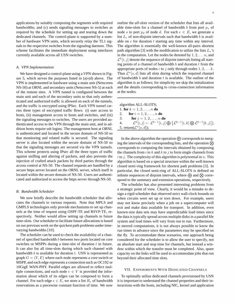
To estimate the jitter levels, we sent packets of fixed sizes(10K) between the hosts and measured the application level de-lays. The variations are shown in Figure 10. The average de-lay is approximately 11 millisec with jitter level of about 2%.While this jitter level is extremely low compared to Internetconnections where the jitter levels could be as much as 30%,control streams for highly sensitive end devices could requirean explicit handling of the jitter.
2) Host Configurations: The storage devices and file sys-tems on unet1 and unet2 are carefully configured to achievethe file access speed of 1Gbps. Specifically, we implementedRAID 0 disk system on both hosts using dual SCSI hard drivesand implemented xfs file system that achieved disk I/O rates inexcess of 1 Gbps.
Note that the measurements in the previous section are col-
protocol throughputTsunami 919 MbpsUDT 890 MbpsFOBS 708 Mbps
TABLE ITHROUGHPUTS ACHIEVED BY VARIOUS UDP-BASED PROTOCOLS FOR
FILE TRANSFERS.
Hurricane sender Hurricane receiver
Receive transmission loss information via TCP
Receiver Buffer
Send transmission loss information via TCP
TCP control channel
UDP datagrams
UDP data channel
retransmission control
reload lost datagrams
Data source
Data sink
write in-order datagrams
Congestion Window
Sleep Time
) ( t W c
) ( t T s
datagram reordering
List of lost datagrams
Fig. 11. Hurricane transport control structure.
lected at the application level, and hence they are subject to pro-cessor scheduling between the application processes and alsobetween application and kernel processes. The measurementscould be significantly affected if other applications are concur-rently running on the hosts since the processor is shared be-tween them. The plots in Figure 8 were collected when no otheruser programs are executed at the hosts, and in that sense repre-sent the best case performance experienced by the applications.Our motivation is to utilize unet1 and unet2 as dedicated hostsfor data transfers. If hosts were to be used as user worksta-tions as well, the throughput profile must be generated underthe normal host conditions. In general, additional applicationsrunning on the host will result in higher application-level lossesand lower goodputs. Also, jitter levels shown in Figure 10 areobserved when no other user level processes are running.
B. Transport Protocols
We consider protocols for data transfers, both memory andfile transfers, and stable control streams. The default TCPthroughputs were below 100 Mbps and could be improved bya factor of 2-3 with parameter tuning. Since dedicated chan-nels do not have competing traffic, UDP-based protocols aremore suited for these channels, although a careful parametertuning was necessary to achieve goodput rates in the vicinity of1Gbps. All UDP protocols we tested for file transfers requiredsome manual parameter tuning to achieve throughputs close to900 Mbps; this process required some understandings of theprotocols and their implementations as well. The details weredifferent among the protocols and it required significant effortsto gain even a partial understanding of the relationship betweenthe parameters and the achieved throughput.
For implementing stable flows, TCP is inherently ill-suited

10
Test link MTU
(bytes) Target rate
(Mbps) Exp.
# Source rate
(Mbps) Goodput (Mbps)
Retxmt rate (%)
1 49.69 49.56 0.016 2 50.66 50.52 0.010 50.0 3 50.75 50.60 0.020 1 202.24 201.76 0.004 2 202.86 202.38 0.005 200.0 3 202.54 202.06 0.004 1 504.32 501.84 0.008 2 505.48 502.12 0.001 500.0 3 506.73 505.40 0.001 1 901.46 896.87 0.004 2 895.13 890.57 0.003 900.0 3 898.61 891.75 0.007 1 945.61 934.15 0.007 2 947.82 939.51 0.005
from unet1 to unet2
1500
950.0 3 950 .56 945.17 0.004 1 991.24 990.48 0.032 2 991.25 990.46 0.036
from unet2 to unet1
9000 1000.0 3 991.27 989.41 0.083
Fig. 12. Hurricane transport test results on unet1 and unet2.
because by default it attempts to infer and occupy the availablebandwidth, which is the entire channel capacity in case of adedicated channel. The sending rate of TCP can be clipped toa desired level by suitably restricting the flow window sizes. Ifthere are no losses, then TCP would indeed maintain the samesending rate. But as indicated by the throughput profile, thenon-zero loss rates at various sending rates result in TCP under-flow, since it interprets the loss as a congestion indication. Also,the randomness of the losses makes the TCP flow stabilizationa difficult task. We tested the recently developed flow stabi-lization method [16] based on stochastic approximation whichprovided quite robust results as will be described in this section.
1) High Throughput Data and File Transfer: Recently re-searchers have been seeking solutions to develop UDP-basedhigh-performance transport protocols that overcome TCP’sthroughput limitation. Such research efforts include SABUL,Tsunami, RBUDP, UDT and others (see [9] for an overview).We tested several of these protocols for file transfers and theirpeak throughput results are shown in Table I. The best perfor-mance we achieved for file transfers is slightly above 900Mbps.It was clear from the throughput profile that goodput rates of990 Mbps are possible if the source rate is suitably maintained.A protocol, called Hurricane [15] is developed exclusively forhigh-speed file transfer on dedicated links. The design goal ofHurricane is to maximize link utilization without any expec-tation of sharing the channel. The architecture of Hurricanetransport is illustrated in Figure 11. The source rate rS(t) of aHurricane sender is controlled by two parameters, congestionwindow size Wc(t) and sleep time Ts(t):
rS(t) =Wc(t)
Ts(t) + Tc(t)=
Wc(t)
Ts(t) + Wc(t)BW
=1.0
Ts(t)Wc(t)
+ 1.0BW
(1)
where Tc(t) = Wc(t)BW is the time spent on continuously sending
a full congestion window of UDP datagrams, which is deter-mined by the congestion window size and link capacity BW,i.e. the maximum speed at which the NIC can generate the bitsignal and put it on wire. According to Eq (1), we may controlthe source rate rS(t) by adjusting either the congestion windowWc(t) or sleep time Ts(t) individually, or both simultaneously.
A Hurricane receiver accepts incoming UDP datagrams,which are either written immediately to the local storage deviceif they arrived in order, or placed temporarily in a buffer forreordering otherwise. Whenever a control event is triggered,a sequential scanning is performed on the receiving buffer tocheck for a list of missing datagrams. The datagram ID num-bers on this list are grouped together and sent over a separateTCP channel to the Hurricane sender. The sender then reloadsthe missing datagrams into the sender congestion window forretransmission upon the receipt of such control strings. To ac-count for the limitations posed by the host side factors, a re-transmission event is triggered based on the number of miss-ing datagrams within a strategically determined time windowof multiple RTT (round trip time) estimates, and we write onlyin-order datagrams on the fly onto the local storage device tosustain a near-peak receiving rate.
We conducted Hurricane transport experiments on 1Gbpsdedicated link between unet1 and unet2 with various levelsof target rates using a 2G bytes test file. Each experiment onone target rate is repeated for 3 times. The performance mea-surements for file transfers are listed in Figure 12. The highthroughput and bandwidth utilization are achieved in both caseswith reasonably low loss rates. Also, we obtain quite stablethroughput when targeting at low rates. The transport controlparameters in these experiments were manually tuned for thebest performance. We observed that the impact of parametertuning on throughput and loss rate at source rates far belowthe peak bandwidth is not as sensitive as those approaching thepeak bandwidth.
2) Stable Control Streams: The architecture of the stabiliza-tion protocol is similar to the one shown in Figure 11 exceptthat the control channel for datagram acknowledgment is alsobuilt over UDP. The rate control is based on the Robbin-MonroStochastic approximation method [11]. At time step n + 1, thenew sleep time is computed as follows to update the sendingrate to a new value (this method is described in detail in [21],[16]):
Ts,n+1 =1.0
1.0Ts,n
−a/Wc
nα ∗ (gn − g∗)
where g∗ is the target rate and gn is the goodput measurement attime step n at the sender side. Coefficients a and α are carefullychosen so that the source rate eventually converges to ensurethe required target rate. The step size denoted by a/nα musteventually become zero such that a/nα → ∞ as n → ∞. Butthe rate of change must be controlled to be neither too fast such
that∞∑
n=1a/nα = ∞, nor too slow such that
∞∑
n=1a2/n2α < ∞.
Under these Robbins-Monroe conditions on step sizes, it canbe analytically shown that this protocol achieves the goodputstabilization at g∗ under random losses and profiles similar toones observed for this link (see [16], [21] for details).

11
X Graph
sendrate.dat (0)
goodput.dat (1)
Y
6X x 10
1.0000
2.0000
3.0000
4.0000
5.0000
6.0000
7.0000
8.0000
9.0000
10.0000
11.0000
12.0000
13.0000
0.0000 50.0000 100.0000 150.0000 (a)X Graph
sendrate.dat (0)
goodput.dat (1)
Y
6X x 105.0000
10.0000
15.0000
20.0000
25.0000
30.0000
35.0000
40.0000
45.0000
50.0000
55.0000
60.0000
65.0000
70.0000
75.0000
80.0000
0.0000 5.0000 10.0000 15.0000 (b)
Fig. 13. Stabilization over the dedicated link: target goodput is 1.0 and 10.0Mbps in (a) and (b) respectively; a = 0.8, α = 0.8 , adjustment is made onsleep time.
We tested this method for flow stabilization on the same ded-icated channel between unet1 and unet2. There is no competingtraffic on this dedicated channel during the time of experiments.A set of control parameters a = 0.8 and α = 0.8 are selectedand the rate adjustments are applied on sleep time only. Insteadof using the default MTU of 1500 bytes in the Internet, we usea MTU of 9000 bytes on this dedicated link. We conductedtwo stabilization experiments targeted at 1.0 and 10.0 Mbps,respectively. The initial sleep time is set to be 100 ms for eachexperiment and the window size is fixed at 2 and 6 datagrams,respectively. The performance measurements of source rate andgoodput are plotted in Fig. 13 where the time axis is in units ofmicroseconds and the rate axis is in units of Mbps. In bothcases, the goodput stabilized at the target rate within secondsand remained constant subsequently.
VIII. CONCLUSIONS
The high-performance networks for large-scale applicationsrequire high bandwidths to support bulk data transfers and sta-ble bandwidths to support interactive, steering and control op-erations. Current IP technologies are severely limited in meet-ing these demands since they are geared to the packet-switchedand shared networks. It is generally believed that the abovenetworking demands can be effectively addressed by provid-ing on-demand dedicated channels of the required bandwidthsdirectly to end users or applications. The UltraScience Net’sgoal is to support the development of these technologies specif-ically targeting the large-scale science applications carried outat national laboratories and the collaborating institutions. USNprovides on-demand dedicated channels: (a) 10Gbps channelsfor large data transfers, and (b) high-precision channels for finecontrol operations. Its design required several new compo-nents including a VPN infrastructure, a bandwidth and channelscheduler, and a dynamic signaling daemon. USN’s initial de-ployment consisting of OC192 SONET and 10GigE WAN PHYconnections from Atlanta to Chicago to Seattle to Sunnyvale isexpected to be operational in early 2005. Its control plane isimplemented using a hardware-based VPN that encrypts all thesignals on the control plane and also provides authenticated andauthorized access. Our future plan include enhancing the data-plane with four 10Gbps wide-area connections, and enhancingthe control-plane to inter-operate with networks supported byGMPLS signaling. We also plan to provide level-2 peering withNSF CHEETAH network [2] using MSPP at ORNL, and lever-3 peering with ESnet and CERN in Chicago and with Internet2in Atlanta.
While USN is being rolled out, we conducted preliminaryexperiments to understand the properties of dedicated channelsusing a smaller scale connection from Oak Ridge to Atlanta.While this 1Gbps channel is limited in its capacity, span and ca-pabilities, these experimental results provided us with valuableinsights into both channel and host aspects of supporting datatransfers over dedicated channels. For USN dedicated channels,which are of much larger capacity and longer distance, we ex-pect our qualitative results to hold although the actual loss andjitter levels might be quite different:
(a) The throughput profile will be qualitatively similar in thatlosses will be non-zero and random at various sendingrates, and jitter levels could be significant for controlstreams.
(b) Host components play a significant role in the performanceseen at the applications level.
(c) Achieving data transfer rates close to the channel capaci-ties would require a careful selection of control parametersand appropriate implementation of protocols.
Our future plans include testing both protocols and applica-tions over USN channels that connect ORNL supercomputersites to user sites. In particular, our plans include developingand testing interactive visualization, monitoring and steeringmodules for Terascale Supernova computations [19] executedon ORNL supercomputers from remote locations connected viaUSN channels.

12
ACKNOWLEDGMENTS
This research is sponsored by High-Performance Networking Program of
Office of Science, U. S. Department of Energy under Contract No. DE-
AC0500OR22725 with UT-Battelle, LLC.
REFERENCES
[1] CERN: The World’s Largest Particle Physics Laboratory.http://http://public.web.cern.ch/Public/Welcome.html.
[2] End-To-End Provisioned Optical Network Testbed for Large-ScaleeScience Application, http://www.ece.virginia.edu/ mv/html-files/ein-home.html.
[3] T. H. Cormen, C. E. Leiserson, and R. L. Rivest. Introduction to Algo-rithms. McGraw-Hill Book Co., New York, 1990.
[4] High-performance networks for high-impact science, 2002. Report ofthe High-Performance Network Planning Workshop, August 13-15, 2002,http://DOECollaboratory.pnl.gov/meetings/hpnpw.
[5] Network provisioning and portocols for DOE large-science applications,2003. Report of DOE Worksshop on Ultra High-Speed Transport Protocoland Dynamic Provisioning for Large-Scale Applications, August 10-11,2003, http://www.csm.ornl.gov/ghpn/wk2003.html.
[6] Doe science networking - roadmap to 2008, 2003. Report available at:http://www.es.net/hypertext/welcome/pr.Roadmap/index.html.
[7] The earth simulator center. http://www.es.jamstec.go.jp/esc/eng/ES/index.html.[8] Energy sciences network. http://www.es.net.[9] A. Falk, T. Faber, J. Banister, A. Chien, R. Grossman, and J. Leigh.
Transport protocols for high performance. Communications of the ACM,46(11):43–49, 2003.
[10] W. C. Grimmell and N. S. V. Rao. On source-based route computation forquickest paths under dynamic bandwidth constraints. Journal on Foun-dations of Computer Science, 14(3):503–523, 2003.
[11] H. J. Kushner and C. G. Yin. Stochastic Approximation Algorithms andApplications. Springer-Verlag, 1997.
[12] NSF Shared Cyberinfrastructure Division PI Meeting, February 18-20,2004, http://http://hpn.east.isi.edu/nsf-sci.
[13] Nsf grand challenges in escience workshop, 2001. Final Report:http://www.evl.uic.edu/activity/NSF/final.html.
[14] N. S. V. Rao, J. Gao, and L. O. Chua. On dynamics of transport protocolsin wide-area internet connections. In L. Kocarev and G. Vattay, editors,Complex Dynamics in Communication Networks. 2004.
[15] N. S. V. Rao, Q. Wu, S. M. Carter, and W. R. Wing. Experimental resultson data transfers over dedicated channels. In First International Workshopon Provisioning and Transport for Hybrid Networks: PATHNETS, 2004.
[16] N. S. V. Rao, Q. Wu, and S. S. Iyengar. On throughput stabilization ofnetwork transport. IEEE Communications Letters, 8(1):66–68, 2004.
[17] Spallation neutron source. http://www.sns.gov.[18] Internet2. http://www.internet2.edu.[19] Terascale supernova initiative. http://www.phy.ornl.gov/tsi.[20] User Controlled LightPath Provisioning, http://phi.badlab.crc.ca/uclp.[21] Q. Wu. Control of Tranport Dynamics in Overlay Networks. PhD thesis,
Louisiana State University, 2003.