ultrasonic level transmitter (hart) - lab-volt · pdf filea ultrasonic level transmitter...
TRANSCRIPT

Instrumentation and Process Control
Ultrasonic Level Transmitter (HART)
Courseware Sample 85991-F0
A


INSTRUMENTATION AND PROCESS CONTROL
ULTRASONIC LEVEL TRANSMITTER (HART)
Courseware Sample
bythe staff
ofLab-Volt Ltd.
Copyright © 2009 Lab-Volt Ltd.
All rights reserved. No part of this publication may be reproduced, in any form or by any means, without the prior written permission of Lab-Volt Ltd.
Printed in CanadaOctober 2009

A Ultrasonic Level Transmitter (HART) v
Foreword
Automated process control offers so many advantages over manual control that the majority of today’s industrial processes use it at least to some extent. Breweries, wastewater treatment plants, mining facilities, the automotive industry, and just about every industry sector use it.
Maintaining process variables such as pressure, flow, level, temperature, and pH within a desired operating range is of the utmost importance to manufacturing products with a predictable composition and quality.
The Instrumentation and Process Control Training System, series 3530, is a state-of-the-art system that faithfully reproduces an industrial environment in which students can develop their skills in the installation and operation of equipment used in the process control field. The use of modern industrial-grade equipment is instrumental in teaching the theoretical and the hands-on knowledge that is required to work in the process control industry.
The modularity of the system allows the instructor to select the equipment required to meet the objectives of a specific course. Two versatile, mobile workstations on which all the equipment is installed are the basis of the system. Several optional components used in pressure, flow, level, temperature and pH control loops are available as well as various valves, calibration equipment, controllers and software.
We hope that your learning experience with the Instrumentation and Process Control Training System will be the first step of a successful career in the process control industry.
a HART® is a registered trademark of the HART Communication Foundation.

A Ultrasonic Level Transmitter (HART) vii
Table of Contents
Exercise 1� Familiarization and Basic Level Measurement .............................. 1�
Introduction. How does an ultrasonic level sensor work? Characteristics of ultrasonic level sensors. Advantages and limitations. Description of the ultrasonic level transmitter. Installing the ultrasonic level transmitter. Commissioning the ultrasonic level transmitter.
Exercise 2� On the Use of Relays ...................................................................... 23�
Programmable relay. Relay control.
Exercise 3� Troubleshooting ............................................................................. 37�
Non-guided troubleshooting.
We Value Your Opinion! ...................................................................................... 39�

Sample Exercise
Extracted from
Student Manual


A Ultrasonic Level Transmitter (HART) 23
Become accustomed to the use of the transmitter relay.
The Discussion of this exercise covers the following points:
� Programmable relay�� Relay control�
Programmable relay
The Ultrasonic Level Transmitter has one programmable relay (SPDT) with a normally-closed (NC) and a normally-open (NO) contact. Terminal 8 is common to both contacts. Terminal 6 is assigned to the NO contact. Terminal 7 is for the NC contact. The state of the relay is shown by a LED on the faceplate of the transmitter (see Figure 14).
Figure 14.� Relay indicating LED.
This relay can be triggered when a limit is reached or when an alarm condition occurs. The relay condition can be used to trigger control elements (e.g. a pump or a solenoid valve), to send a message to a controller, or to actuate an alarm. The relay configuration menu is accessible through:
main menu � relay/controls � relay configurat. � relay 1 : ______ �
On the Use of Relays
Exercise 2
EXERCISE OBJECTIVE
DISCUSSION OUTLINE
DISCUSSION
Relay 1 LED
Exercise 2 – On the Use of Relays � Discussion
24 Ultrasonic Level Transmitter (HART) A
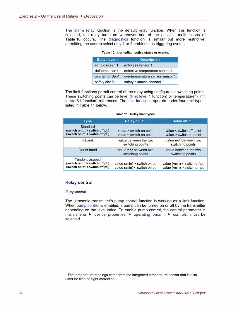
The alarm relay function is the default relay function. When this function is selected, the relay turns on whenever one of the possible malfunctions of Table 10 occurs. The diagnostics function is similar but more restrictive, permitting the user to select only 1 or 2 problems as triggering events.
Table 10.� �larm/diagnostics states or events.
State / event Descriptionecholoss sen 1 echoless sensor 1 def temp. sen1 defective temperature sensor 1 overtemp. Sen1 overtemperature sensor sensor 1 safety dist S1 safety distance channel 1
The limit functions permit control of the relay using configurable switching points. These switching points can be level (limit level 1 function) or temperature1 (limit temp. S1 function) references. The limit functions operate under four limit types, listed in Table 11 below.
Table 11.� Relay limit types.
Type Relay on if… Relay off if…Standard
(switch on pt.> switch off pt.) (switch on pt.< switch off pt.)
value > switch on point value < switch on point
value < switch off point value > switch on point
Inband value between the two switching points
value not between two switching points
Out of band value not between two switching points
value between the two switching points
Tendency/speed (switch on pt.> switch off pt.) (switch on pt.< switch off pt.)
value (/min) > switch on pt. value (/min) < switch on pt.
value (/min) < switch off pt. value (/min) > switch on pt.
Relay control
Pump control
The ultrasonic transmitter’s pump control function is working as a limit function. When pump control is enabled, a pump can be turned on or off by the transmitter depending on the level value. To enable pump control, the control parameter in main menu � device properties � operating param. � controls. must be selected.
1 The temperature readings come from the integrated temperature sensor that is also used for time-of-flight correction.

Exercise 2 – On the Use of Relays � Discussion
A Ultrasonic Level Transmitter (HART) 25
Example 1 – Water supply
In the arrangement shown below, a pump is located outside the column and feeds water to the column. The pump turns on when the level is low and switches off when the level is high, so that the level is kept within a specific range.
Solenoid valve control
Using the level limit function, it is possible to set the opening and closing of a solenoid valve at precise level values.
Example 2 – Overflow control
In the configuration shown below, a solenoid valve is controlling the output flow of a column to prevent the water from overflowing. The valve opens when the level is high and closes when the level is low.
Pump
Solenoid valve

Exercise 2 – On the Use of Relays � Procedure Outline
26 Ultrasonic Level Transmitter (HART) A
The Procedure is divided into the following sections:
� Installation procedure�� Setup�� Overflow control with a solenoid valve�� Cleaning up and storing�
Installation procedure
1. Arrange the process workstation in the basic setup configuration as described in the Familiarization with the Instrumentation and Process Control Training System manual. Make sure the column is empty, the power is off, and the hand valves are closed.
2. If a flange top is already in place on the process column, unbolt and carefully remove this component from the column. Place the sensor part of the ultrasonic level transmitter on top of the flange, the sensor pointing downwards into the column. Bolt the sensor in place.
Install the digital transmitter at a convenient location on the instrumentation workstation. Connect the sensor cable to the connection jacks on the transmitter. Be sure to respect the color code for each lead (Figure 15).
Figure 15.� Ultrasonic level transmitter installed on the workstations.
3. Connect the transmitter to a 24 V dc power outlet on the electrical unit. Use one of the direct outputs to keep the transmitter from shutting off in case the emergency push-button or the OFF button (S2) is used.
4. Make sure it is safe to energize the system for you AND for the team working on the other side of the system if it is the case. When ready, turn on the main
PROCEDURE OUTLINE
PROCEDURE

Exercise 2 – On the Use of Relays � Procedure
A Ultrasonic Level Transmitter (HART) 27
power by pushing the handle of the safety switch in the ON position. Do not press the S1 button yet.
The transmitter lights up, initializes and shows its main display after a few seconds.
Setup
5. Reset and configure the Ultrasonic Level Transmitter according to the Commissioning the ultrasonic level transmitter section of Exercise 1.
6. Go to main menu � device properties � operating param. Under the controls tab, select pump control (default is no).
You should now see two new options in main menu � relay/controls., namely pump control 1 and pump control 2. Select pump control 1. Choose level 1 as the reference. Number of pumps remains at 1.
Under main menu � relay/controls � relay configurat., select limit level 1 for relay 1. This takes you to the relay 1 configuration menu. Set the parameters as follows in the two tabs:
Table 12.� Relay 1 configuration (tab 1).
Relay 1 function: limit level 1 limit type: standard switch on point: 0.000% switch off point: 60.000%
Table 13.� Relay 1 configuration (tab 2).
Relay 1 switch delay: 0 invert: no error handling: actual value

Exercise 2 – On the Use of Relays � Procedure
28 Ultrasonic Level Transmitter (HART) A
7. Complete the process loop as shown in Figure 16 and Figure 17. Use elbows as appropriate and make sure the hand valves are as in the shown position. Close all unused ports on the column with an end cap.
Figure 16.� P&ID - Exercise 2 (pump control).

Exercise 2 – On the Use of Relays � Procedure
A Ultrasonic Level Transmitter (HART) 29
Figure 17.� Setup – Exercise 2 (pump control).
8. Connect the ultrasonic transmitter and the electrical unit according to Figure 18. If the relay operation is not inverted, the pump will turn on when the relay NO contact is closed, that is to say with the level at 0%. The pump will stop when the relay NO contact is open, at a level of 60%.

Exercise 2 – On the Use of Relays � Procedure
30 Ultrasonic Level Transmitter (HART) A
Figure 18.� Relay connections.
9. If you share a pump with another team, first make sure it is safe to proceed for both teams. Press the S1 button to power the drive. Start the pump at a slow speed and slowly open HV 2. Water should circulate in the process loop. Increase the speed of the pump, test the loop for leaks and fix them as required. Press the S2 button and close HV 2.
10. Change the drive Start Source (P36) parameter to “2-Wire Hi Speed” (i.e. 4). With this parameter, the drive starts the pump when a 24-V dc signal is applied to terminal 02 (contact “S4”) on the Electrical Unit. Conversely, the drive stops the pump when no signal is present at this terminal.
a The drive will not start unless a 24-V dc signal is also present at terminal 01 (contact “S3”) of the electrical panel.
The HV 4 hand valve is used to control the outflow of water from the column to the tank. Close the HV 4 hand valve.
11. Set the pump speed knob to about 30%. Press the S1 button to power the drive and open HV 2 completely.
At which tank water level should the pump stop?
Is this what you observe?
12. Open HV 4 hand valve completely.
Electrical unit (46970)
Ultrasonic transmitter (46930)

Exercise 2 – On the Use of Relays � Procedure
A Ultrasonic Level Transmitter (HART) 31
At which tank water level should the pump restart? Is this what you observe?
13. Close HV 4 valve completely and wait for the pump to come to a stop. Turn the drive knob to the minimum position and set the drive Start Source (P36) parameter back to the original parameter (default is “0”).
14. Close HV 2 and press the S2 button.
Overflow control with a solenoid valve
15. Remove the cable linking terminal 7 of the ultrasonic transmitter and terminal 02 of the electrical unit.
16. Go to main menu � device properties � operating param. Under the controls tab, select no instead of pump control.
Exercise 2 – On the Use of Relays � Procedure
32 Ultrasonic Level Transmitter (HART) A
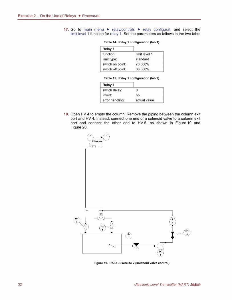
17. Go to main menu � relay/controls � relay configurat. and select the limit level 1 function for relay 1. Set the parameters as follows in the two tabs:
Table 14.� Relay 1 configuration (tab 1).
Relay 1 function: limit level 1 limit type: standard switch on point: 70.000% switch off point: 30.000%
Table 15.� Relay 1 configuration (tab 2).
Relay 1 switch delay: 0 invert: no error handling: actual value
18. Open HV 4 to empty the column. Remove the piping between the column exit port and HV 4. Instead, connect one end of a solenoid valve to a column exit port and connect the other end to HV 5, as shown in Figure 19 and Figure 20.
Figure 19.� P&ID - Exercise 2 (solenoid valve control).

Exercise 2 – On the Use of Relays � Procedure
A Ultrasonic Level Transmitter (HART) 33
Figure 20.� Setup – Exercise 2 (solenoid valve control).
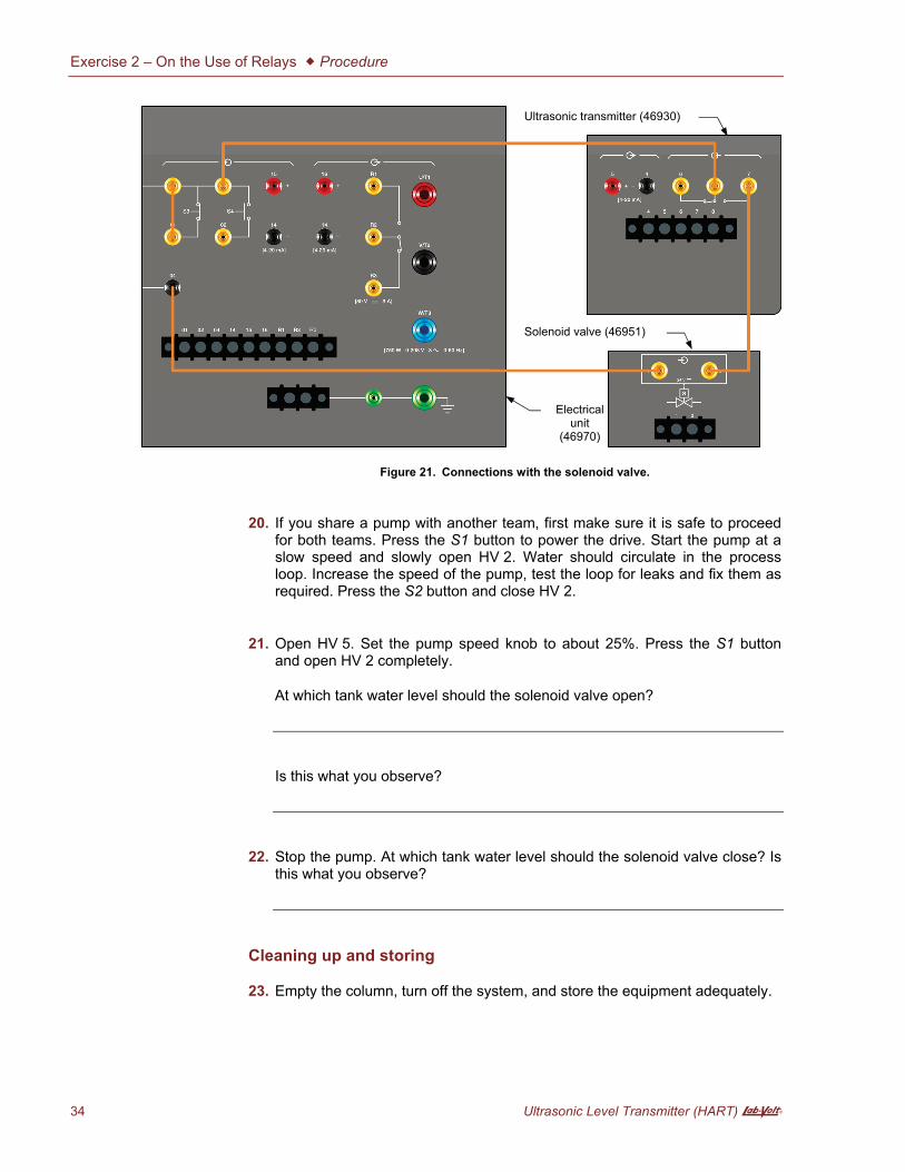
19. Connect one of the terminals of the solenoid valve to a common terminal on the electrical unit. Connect the second terminal of the solenoid valve to terminal 7 (NO contact) of the ultrasonic transmitter. Keep the cable between terminal 8 of the ultrasonic transmitter and the electrical unit. These connections are depicted in Figure 21.
Exercise 2 – On the Use of Relays � Procedure
34 Ultrasonic Level Transmitter (HART) A
Figure 21.� Connections with the solenoid valve.
20. If you share a pump with another team, first make sure it is safe to proceed for both teams. Press the S1 button to power the drive. Start the pump at a slow speed and slowly open HV 2. Water should circulate in the process loop. Increase the speed of the pump, test the loop for leaks and fix them as required. Press the S2 button and close HV 2.
21. Open HV 5. Set the pump speed knob to about 25%. Press the S1 button and open HV 2 completely.
At which tank water level should the solenoid valve open?
Is this what you observe?
22. Stop the pump. At which tank water level should the solenoid valve close? Is this what you observe?
Cleaning up and storing
23. Empty the column, turn off the system, and store the equipment adequately.
Solenoid valve (46951)
Electrical unit
(46970)
Ultrasonic transmitter (46930)

Exercise 2 – On the Use of Relays � Conclusion
A Ultrasonic Level Transmitter (HART) 35
In this exercise, you used the relay of the ultrasonic level transmitter to control a pump and a solenoid valve to keep the water level in a column within predetermined boundaries.
1. When is the ultrasonic relay triggered?
2. What can the relay condition be used for?
3. What is the default relay function on the ultrasonic transmitter?
4. What is the difference between alarm relay and diagnostics functions?
5. What are the four relay limit types?
CONCLUSION
REVIEW QUESTIONS


Sample
Extracted from
Instructor Guide


Exercise 2 On the Use of Relays
A Ultrasonic Level Transmitter (HART) 5
Exercise 2 On the Use of Relays
11. The pump should stop when the level reaches 60%.
12. The pump should restart when the level reaches 0%.
21. The solenoid valve should open when level reaches 70%.
22. The solenoid valve should close when level reaches 30%.
1. The relay is triggered when a limit is reached or when an alarm condition occurs.
2. The relay condition can be used to trigger a control element, to send a message to a controller, or to actuate an alarm.
3. Alarm relay
4. Alarm relay reacts to any possible trouble while diagnostics only reacts to one or two selected troubles.
5. Standard, Inband, Out of band, Tendency/speed
ANSWERS TO PROCEDURE STEP QUESTIONS
ANSWERS TO REVIEW QUESTIONS