uml unified modeling language. credits wolfgang pelz uml-diagrams.org emanuele debenedetti
TRANSCRIPT
UML
Unified Modeling Language
Credits
• Wolfgang Pelz• uml-diagrams.org• Emanuele Debenedetti

History
• Booch: Booch Method• Rumbaugh: OMT (object modeling technique)• Jacobson: OOSE (OO software engineering)


Another organization

Class diagram
• static view of a system in terms of classes and relationships among the classes– associations– subtypes
• typically done in parallel with interaction diagrams
• a more graphical alternative to CRC cards

Common uses
• Provide a view of services the system should provide to its end user
• Model the vocabulary of a system• Model simple collaborations• Model a logical database schema
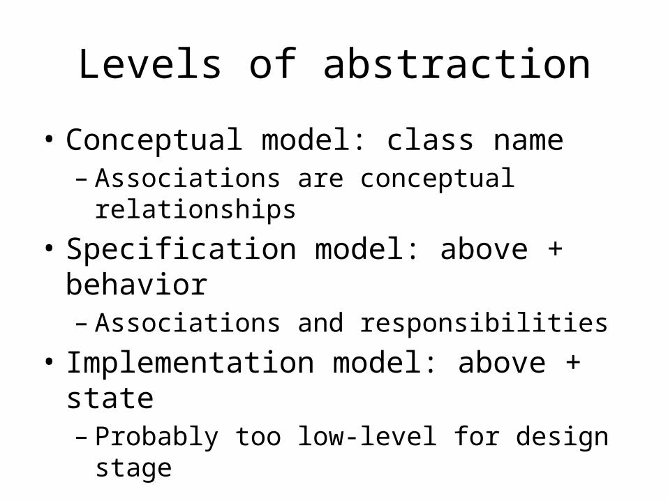
Levels of abstraction
• Conceptual model: class name– Associations are conceptual relationships
• Specification model: above + behavior– Associations and responsibilities
• Implementation model: above + state– Probably too low-level for design stage
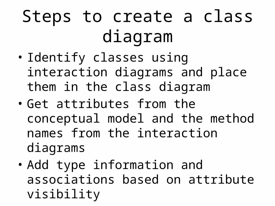
Steps to create a class diagram
• Identify classes using interaction diagrams and place them in the class diagram
• Get attributes from the conceptual model and the method names from the interaction diagrams
• Add type information and associations based on attribute visibility
• Add navigability arrows and dependencies

Cautions
• Start small• Perspective should match activity
– analysis: conceptual model– software: specification model
• Don’t go to details too early

Classes
• Classes comprise three slots (the forth is optional)– Name– Attributes (state)– Methods (behavior)
Professor
namesurname
create()delete()
Professor
create()delete()
Professor
namesurname
Professor

Classes(Visibility and multiplicity)
• Attribute: visibility name: type [multiplicity] = default {further properties}• Method: visibility name (parameter list): returned type {further properties}• Visibility: + public, - private, # protected, ~ friendly• Parameter: direction name: type = default
name: Stringsurname: Stringage: integer
visualize()selectCourse()
Professor
Professor
+ name: String# surname: String - age: integer = 33
+visualize()- selectCourse()
public
protected
private

Associations
• Describe relations between classes• Associations have roles (given at the end of the
association) which have multiplicities• Associations have navigability
– A sends a message to B– A creates an instance of B– A needs to maintain a connection with B
• Navigability is identified from collaboration diagrams

Roles
• Define the roles played in associations• Useful for
– Self-associations– Multiple associations between the same two classes
work forPerson Company
employee eployer
1..* 0..1
Person
0..1
0..1
husband
wife
is merried toUser Directory
owner
ack. user
container
contained
0..*
0..*
0..*
0..*1

Example
class Persona { private String nome; private String cognome; private Date dataNascita; private static int numPersone; public Persona marito; public Persona moglie;
public boolean siSposa(Persona p) { … }
public boolean compieAnni(Date d) { … }}
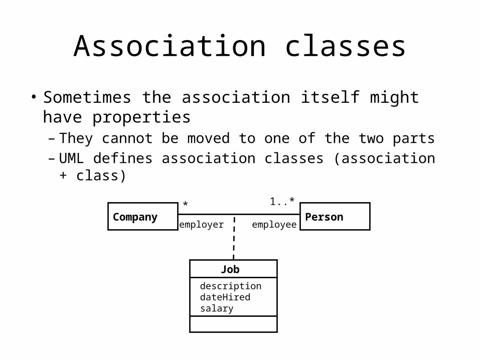
Association classes
• Sometimes the association itself might have properties– They cannot be moved to one of the two parts – UML defines association classes (association + class)
Company Person
JobdescriptiondateHiredsalary
* 1..*
employer employee

Aggregations
• They are specialized associations that stress the containment between the two classes
• We have a part-of relationship
Course Curriculum1..* 0..*

Composites
• Composites are heavy aggregations– The contents is subordinated to the container– For example, deleting the container means deleting
the contents as well
SliderPanel Button
Window
scrollbar body close2
1 1
1
1
1

Inheritance (Generalization)
• Makes common properties explicit
• Inheritance is an elegant modeling means, but– It is not mandatory– Maybe we must add
properties– Maybe we must refine/modify
other properties• We can work
– Bottom-up (Generalization)– Top-down (Specialization)
Person
Student Professor

Inheritance and abstract classes
• Abstract classes – Aggregate common
properties– They are inherited by
all subclasses• Inheritance and
abstract classes provide an elegant and synthetic modeling means
Polygon Circle
Shape
Triangle Square
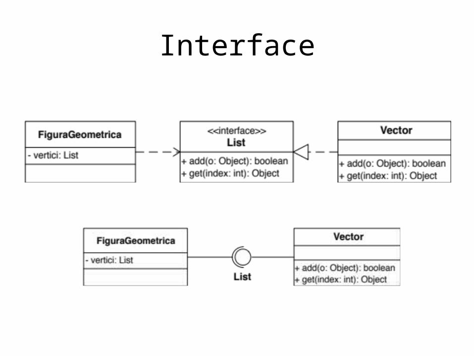
Interface

Dependency relationship
• One element (of any kind, including classes, use cases, etc.) has knowledge of another element– If one element changes, the other might have to
change as well– Differs from plain attribute visibility which uses
regular association line and a navigability arrow

Example

Interface
• Interface is a class of abstract/pure virtual functions
• All functions in the interface are public• Interface cannot be used to instantiate objects• There is no data members in an interface class• UML: use <<interface>> to prefix the class
name


Object diagram• Also called instance diagrams• Useful of showing object connections (not interactions)• Can be thought of as collaboration/communication diagram without messages

Package diagram

Model diagram

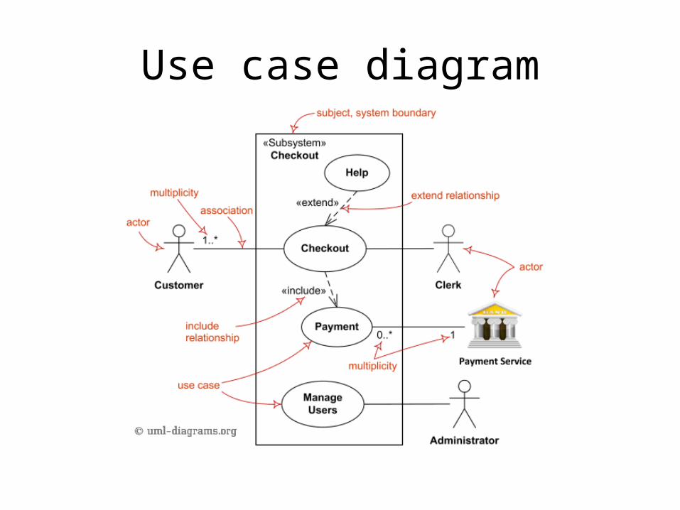
Use case diagram
• For capturing the functional requirements of a system
• Typical interaction between user and system– captures some user-visible function– achieves a discrete goal for the user
• System interaction is the low-level work that ultimately achieves the user goal

Common uses
• To model the context of a system– System, actors, and their interactions with it
• To model the requirements of a system– What system should do – Independent of how it is done– Point of view outside of system
Use case diagram
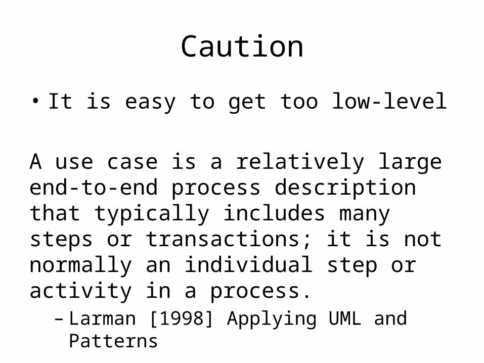
Caution
• It is easy to get too low-level
A use case is a relatively large end-to-end process description that typically includes many steps or transactions; it is not normally an individual step or activity in a process.
– Larman [1998] Applying UML and Patterns
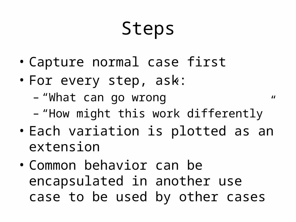
Steps
• Capture normal case first• For every step, ask:
– “What can go wrong”– “How might this work differently”
• Each variation is plotted as an extension• Common behavior can be encapsulated in
another use case to be used by other cases

Interaction diagrams
• Models that describe how groups of objects interact (collaborate)
• Class and use case diagrams are useful at capturing the structural nature of a system design in a generalized way
• Interaction diagrams capture dynamic behavior applicable to timing or sequencing requirements

Use case and Interaction diagrams
• Scenario - a specific instance of a use case, that is, a particular path through system functionality
• A single use case represents many related yet distinctly different scenarios
• Typically, an interaction diagram captures the behavior of a single scenario
• Two forms of interactive diagrams: sequence and collaboration/communication

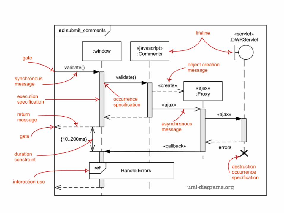
Sequence
• Boxes at the top are participants (objects)• Vertical lines are time lines • Horizontal directed lines are messages• Unless specifically noted, only sequence (location
on the time line) is important, not exact times• An activation rectangle in the lifeline indicates a
focus of control (activation) during which an object is performing an action, either directly or through another object

First example
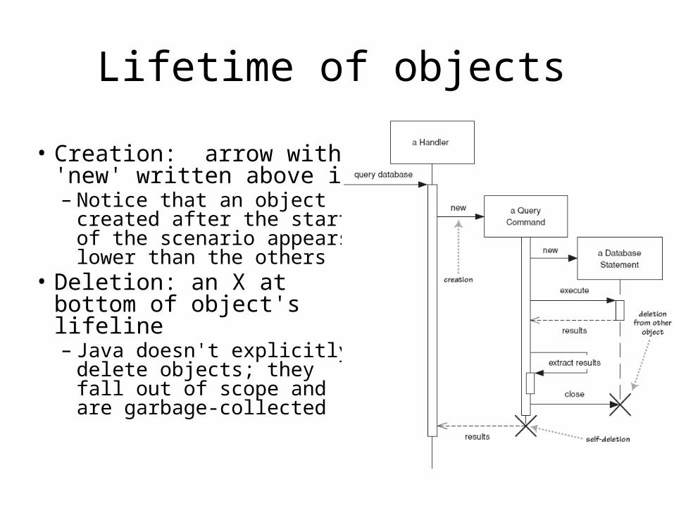
Lifetime of objects
• Creation: arrow with 'new' written above it– Notice that an object
created after the start of the scenario appears lower than the others
• Deletion: an X at bottom of object's lifeline– Java doesn't explicitly
delete objects; they fall out of scope and are garbage-collected

More elements• Messages are function calls in traditional programming and events in event-driven
programming• Messages may carry parameters• A dashed line indicates a return, used to carry a return message or just indicate the
end of a group of sub-actions• Self-call: sending messages to one self (message lines direct back to the same life line)• Found message: messages not originated from any participants.• Synchronous message: messages return only when done, block the flow of execution,
no more messages from the same participant until a synchronous message is done• Asynchronous message: messages returns immediately, do not block the flow of
execution• Guards are conditional expressions in square
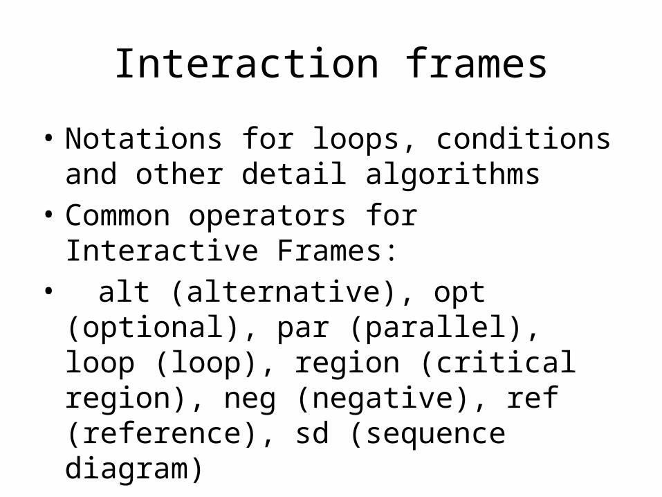
Interaction frames
• Notations for loops, conditions and other detail algorithms
• Common operators for Interactive Frames:• alt (alternative), opt (optional), par
(parallel), loop (loop), region (critical region), neg (negative), ref (reference), sd (sequence diagram)

42
Indicating selection and loops• frame: box around part of a sequence diagram to indicate selection or loop
– if -> (opt) [condition]– if/else -> (alt) [condition], separated by horiz. dashed line– loop -> (loop) [condition or items to loop over]
[balance <> 0]opt [balance < 100.00]
[balance >= 100.00]
alt
[balance < 0]loop

linking sequence diagrams
• If one sequence diagram is too large or refers to another diagram, indicate it with either:– An unfinished arrow and comment– A "ref" frame that names the other diagram– When would this occur in our system?
Verify customer credit
refCustomer Info
Approved?

44
(De)centralized system control
• What can we say about the control flow of each of the following systems?– centralized?– distributed?

Collaboration (UML 1.x)Communication (UML 2.x)
• An interaction diagram that utilizes message numbering instead of a time line; emphasizes structural organization of objects that send and receive messages

Sequence diagram
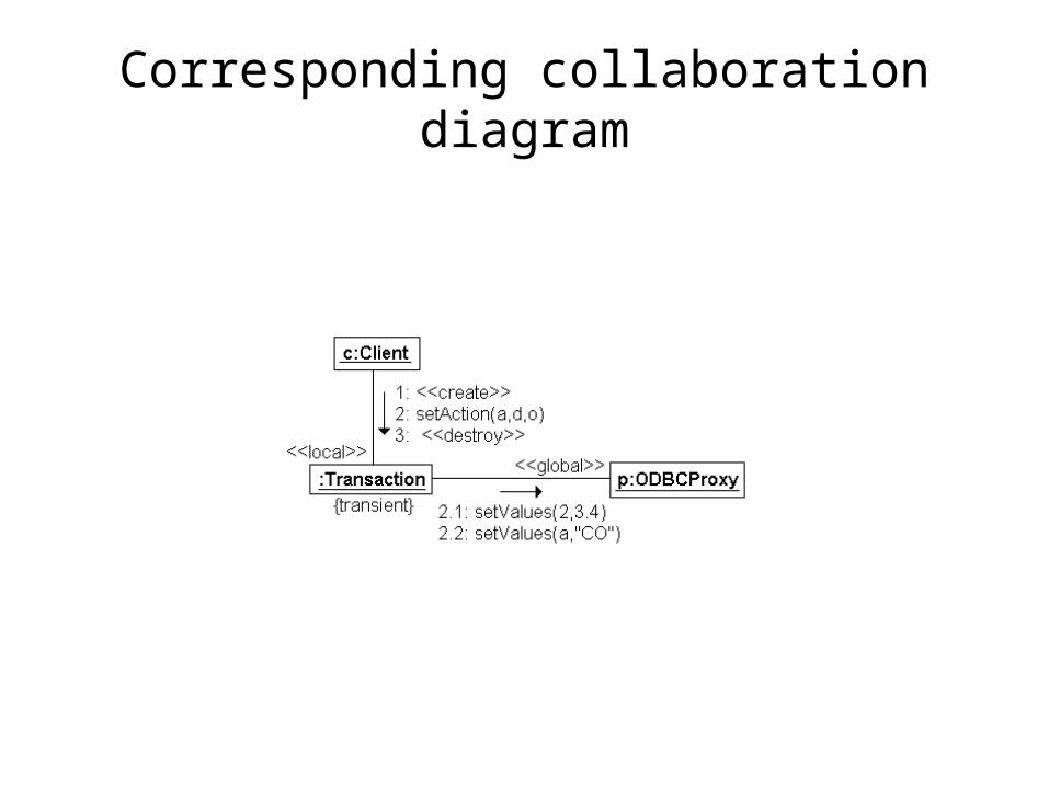
Corresponding collaboration diagram

Which to use?
• Choose sequence diagram when only the sequence of events needs to be shown and collaboration among the objects are priority
• Choose a collaboration/communication diagram when the objects and their links facilitate understanding the interactions
• Collaboration diagrams have relatively fixed notation and numbering scheme

Links and messages

Parameters and return values
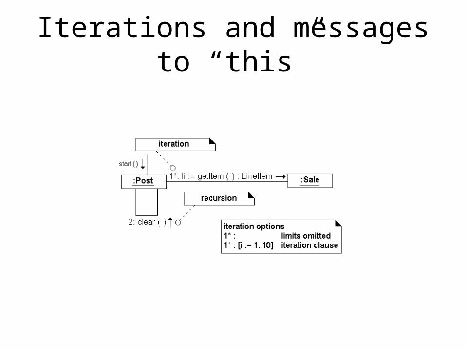
Iterations and messages to “this”

Message Sequencing

Activity diagrams
• Useful to specify software or hardware system behavior• Based on data flow models – a graphical representation
(with a Directed Graph) of how data move around an information system
FillOrder
ShipOrder
SendInvoice
AcceptPayment
CloseOrder
Make Payment
[orderaccepted]
Invoice
ReceiveOrder
[order reject]

Actions
• The fundamental unit of executable functionality in an activity
• The execution of an action represents some transformations or processes in the modeled system

Pins
• Actions can have inputs and outputs, through the pins• Hold inputs to actions until the action starts, and hold the
outputs of actions before the values move downstream• The name of a pin is not restricted: generally recalls the
type of objects or data that flow through the pin
Output pinsStandalone pin notations:
the output pin and the input pin have the same name and
same type
Input pins
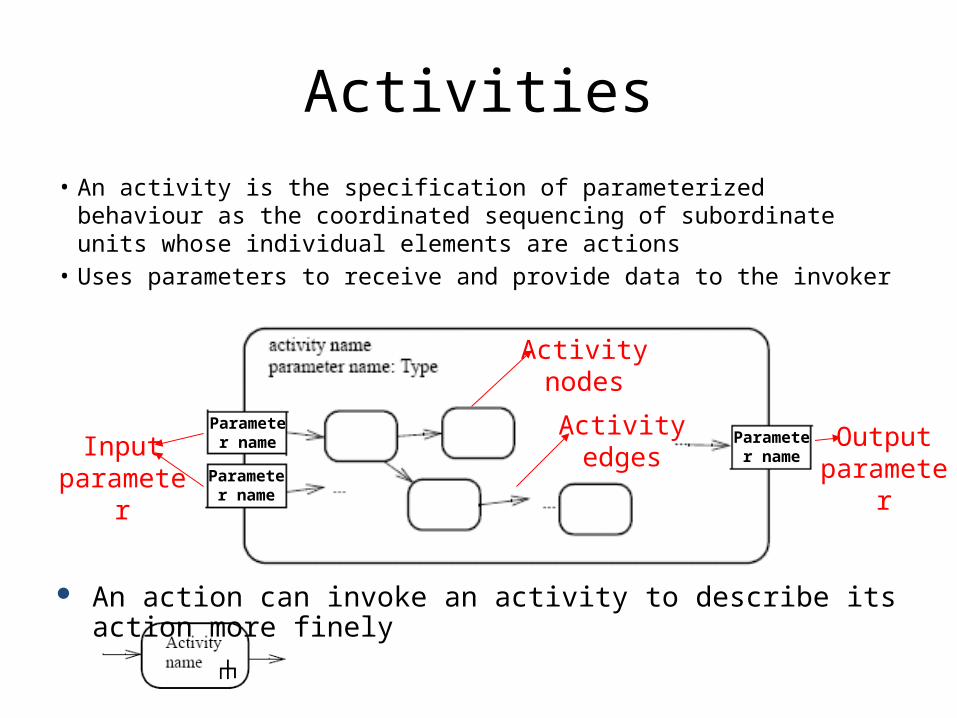
Activities• An activity is the specification of parameterized behaviour as the
coordinated sequencing of subordinate units whose individual elements are actions
• Uses parameters to receive and provide data to the invoker
Parameter name
Parameter name Parameter
nameOutput
parameter
Activity nodes
Activity edgesInput
parameter
An action can invoke an activity to describe its action more finely
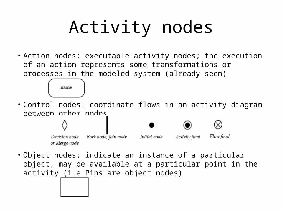
Activity nodes• Action nodes: executable activity nodes; the execution of an action
represents some transformations or processes in the modeled system (already seen)
• Control nodes: coordinate flows in an activity diagram between other nodes
• Object nodes: indicate an instance of a particular object, may be available at a particular point in the activity (i.e Pins are object nodes)

Activity edges• Control flow edge - is an edge which starts an activity node after the
completion of the previous one by passing a control token
• Object flow edge - models the flow of values to or from object nodes by passing object or data tokens
• Weight can determine the minimum number of tokens that must traverse the edge at the same time
Decision nodes
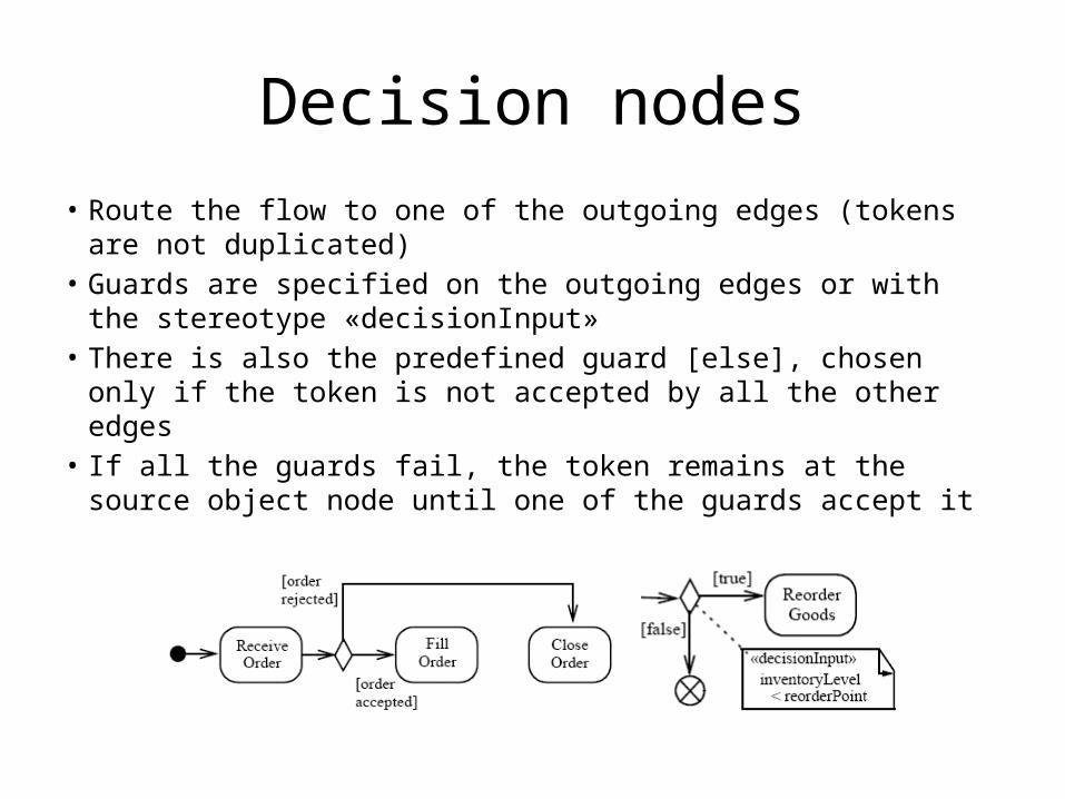
• Route the flow to one of the outgoing edges (tokens are not duplicated)
• Guards are specified on the outgoing edges or with the stereotype «decisionInput»
• There is also the predefined guard [else], chosen only if the token is not accepted by all the other edges
• If all the guards fail, the token remains at the source object node until one of the guards accept it
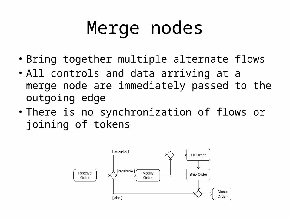
Merge nodes
• Bring together multiple alternate flows• All controls and data arriving at a merge node
are immediately passed to the outgoing edge• There is no synchronization of flows or joining
of tokens

Fork nodes
• Fork nodes split flows into multiple concurrent flows (tokens are duplicated)
• UML 2.0 activity forks model unrestricted parallelism
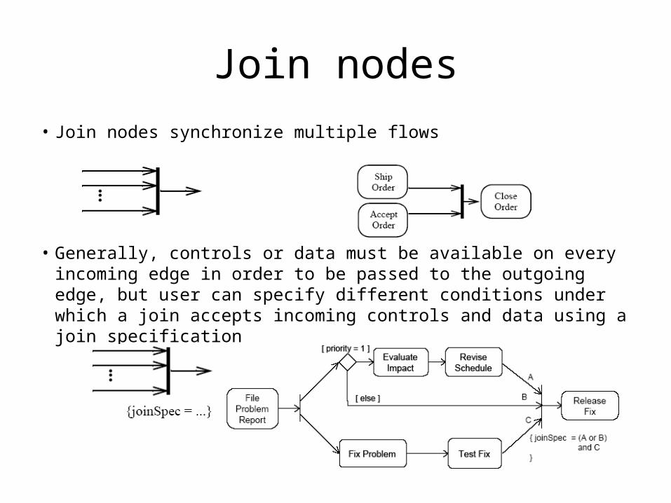
Join nodes• Join nodes synchronize multiple flows
• Generally, controls or data must be available on every incoming edge in order to be passed to the outgoing edge, but user can specify different conditions under which a join accepts incoming controls and data using a join specification
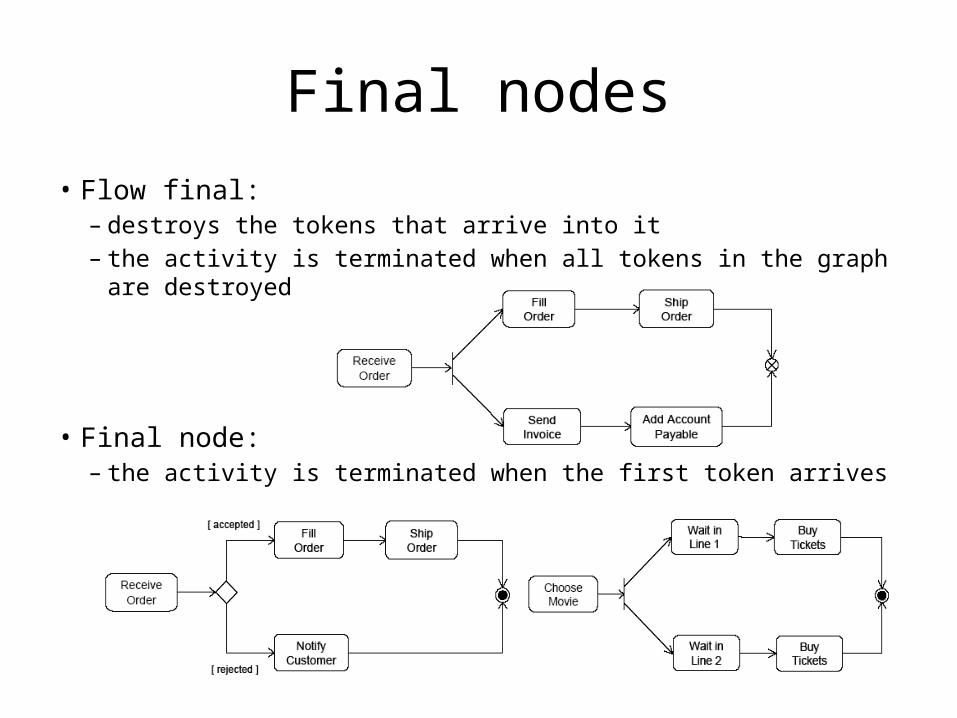
Final nodes
• Flow final:– destroys the tokens that arrive into it– the activity is terminated when all tokens in the graph are destroyed
• Final node:– the activity is terminated when the first token arrives
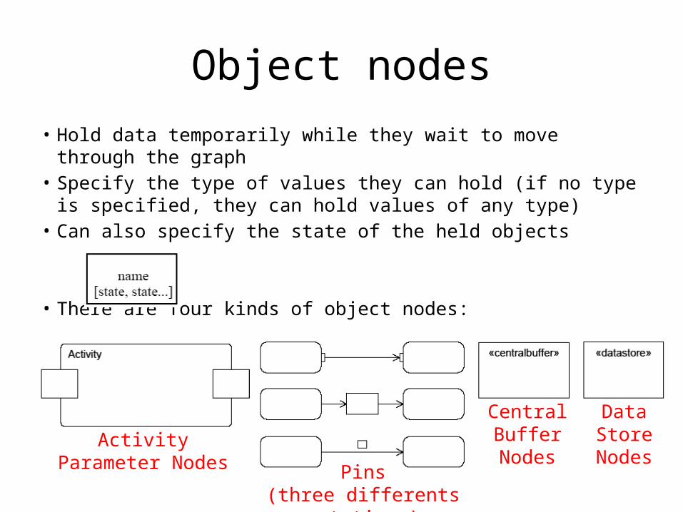
Object nodes• Hold data temporarily while they wait to move through the graph• Specify the type of values they can hold (if no type is specified,
they can hold values of any type)• Can also specify the state of the held objects
• There are four kinds of object nodes:
Pins(three differents notations)
Activity Parameter Nodes
Central Buffer Nodes
Data Store Nodes

Activity edges - transformation
• It is possible to apply a transformation of tokens as they move across an object flow edge (each order is passed to the transformation behaviour and replaced with the result)
In this example, the transformation gets the value of the attribute Customer of
the Order object
<<transformation>>
transformation specification
68
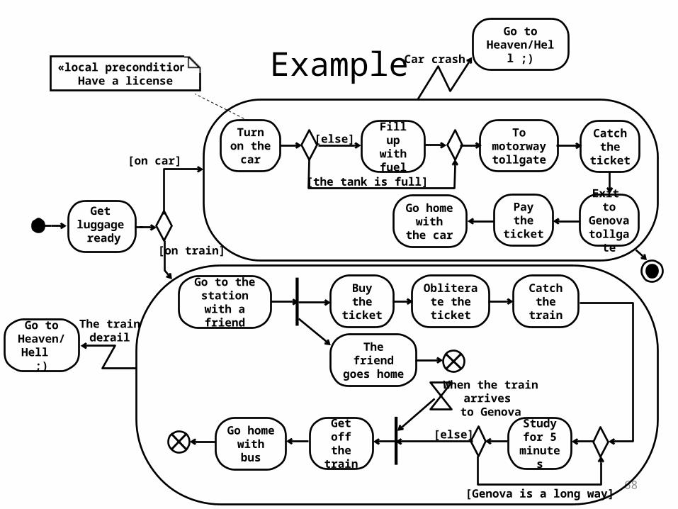
Example
Get luggage
ready
[on car]
[on train]
«local precondition»Have a license
Turn on the car
To motorway
tollgate
Exit to Genova tollgate
Go home with the
car
Go to the station with a
friend
Buy the ticket
Obliterate the ticket
Catch the train
When the trainarrives
to Genova
Get off the train
The trainderail
Car crash
The friend goes home
Go home with bus
Go to Heaven/Hell ;
)
Go to Heaven/Hell ;)
Study for 5
minutes
[Genova is a long way]
[else]
Catch the
ticket
Fill up with fuel
[the tank is full]
[else]
Pay the ticket
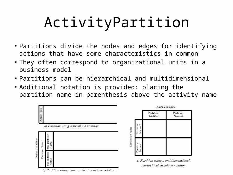
ActivityPartition• Partitions divide the nodes and edges for identifying actions that
have some characteristics in common• They often correspond to organizational units in a business model• Partitions can be hierarchical and multidimensional• Additional notation is provided: placing the partition name in
parenthesis above the activity name

Example
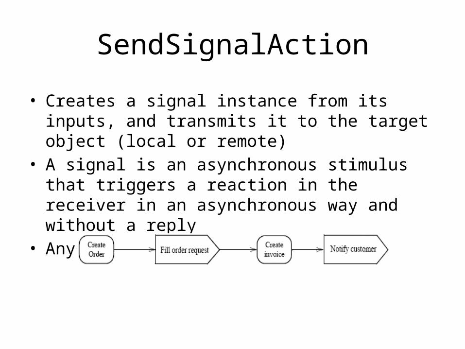
SendSignalAction
• Creates a signal instance from its inputs, and transmits it to the target object (local or remote)
• A signal is an asynchronous stimulus that triggers a reaction in the receiver in an asynchronous way and without a reply
• Any reply message is ignored

Time triggers and Time events
• A Time trigger is a trigger that specifies when a time event will be generated
• Time events occur at the instant when a specified point in time has transpired
• This time may be relative or absolute– Relative time trigger: is specified with the keyword ‘after’
followed by an expression that evaluates to a time value– Absolute time trigger: is specified as an expression that
evaluates to a time value
Jan, 1, 2000, Noonafter (5 seconds)

AcceptEventAction
• Waits for the occurrence of an event meeting specified conditions
• Two kinds of AcceptEventAction:– Accept event action – accepts signal
• events generated by a SendSignalAction
– Wait time action – accepts time events
Accept event action
Wait time action
The objects stored in Personnel are only retrieved when the join succeeds (only
once a year)

InterruptibleActivityRegion• Is an activity group (sets of nodes and edges) that supports termination of
tokens flowing into it• When a token leaves an interruptible region via interrupting edges, all
tokens and behaviours in the region are terminated• Token transfer is still atomic: a token transition is never partial; it is either
complete or it does not happen at all (also for internal stream)
Interrupting edge
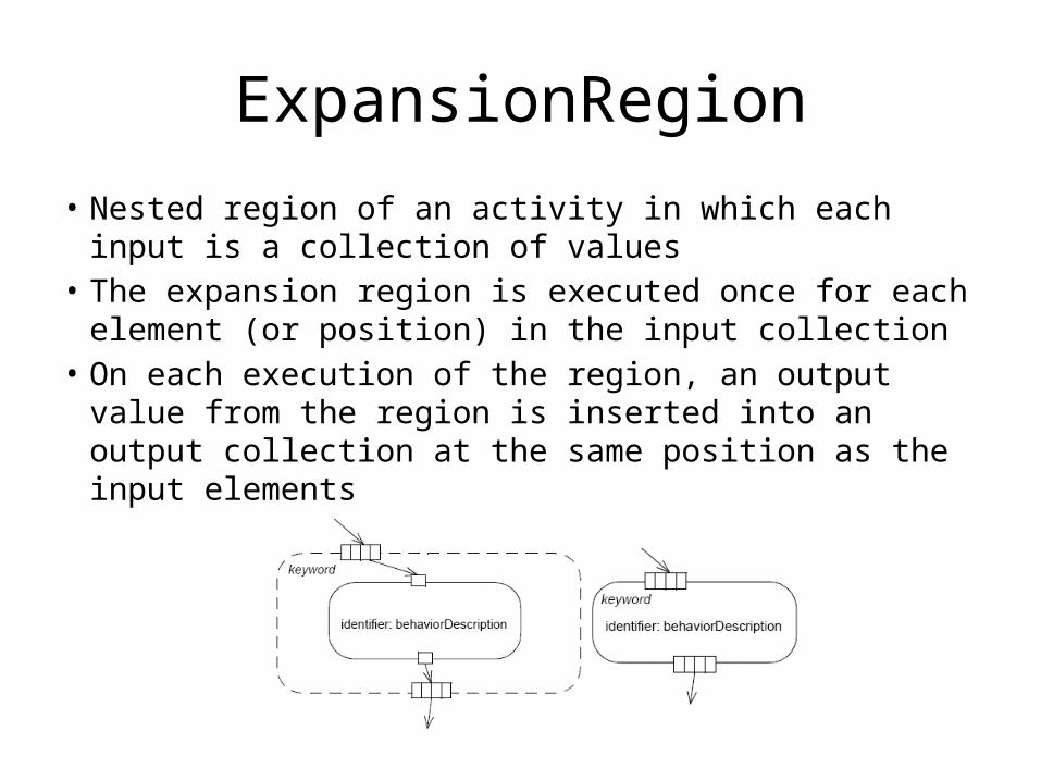
ExpansionRegion
• Nested region of an activity in which each input is a collection of values
• The expansion region is executed once for each element (or position) in the input collection
• On each execution of the region, an output value from the region is inserted into an output collection at the same position as the input elements

State machine diagrams
On FirstFloor
MovingUp
IdleMovingDown
Moving toFirst Floor
up floor
arrive atfloor
up floor
arrive at floor
down floor
time-out
arrive atfirst floor
transition state
An Elevator

State machine diagrams
• A state machine diagram models the behavior of a single object– Specifies the sequence of events that an object
goes through during its lifetime in response to events

States
• States
• Initial and Final States
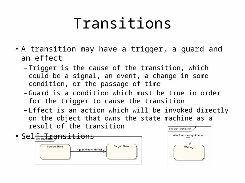
Transitions
• A transition may have a trigger, a guard and an effect– Trigger is the cause of the transition, which could be a signal,
an event, a change in some condition, or the passage of time– Guard is a condition which must be true in order for the
trigger to cause the transition– Effect is an action which will be invoked directly on the object
that owns the state machine as a result of the transition• Self-Transitions
State actions
• Effects can be associated with states• Possible triggers
– Any event– Entry: behavior performed upon entry to the state– Do: ongoing behavior, performed as long as the
element is in the state– Exit: behavior performed upon exit from the state
• It is possible to define any number of actions of each type

Compound states

Entry and exit points
• Entry Points help define alternative initial states
• Exit Points help specify alternative exit points
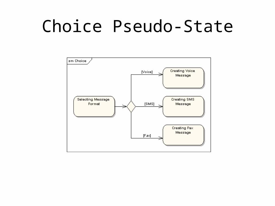
Choice Pseudo-State

Junction Pseudo-State

Pseudo-state and history
• Entering a terminate pseudo-state indicates that the lifeline of the state machine has ended
• A history state is used to remember the previous state of a state machine when it was interrupted

Concurrent regions

Interaction overview
diagrams

Composite structure diagrams

Component diagrams

Deployment diagrams