uncertainty analysis on lwr and htgr neutronics modeling ... · uncertainty analysis on lwr and...
TRANSCRIPT

Uncertainty analysis on LWR and HTGR neutronics modeling using SCALE tools at NCSU
Jason HouDepartment of Nuclear EngineeringNorth Carolina State University
SCALE Users’ Group WorkshopSeptember 27, 2017
Oak Ridge National Laboratory
North Carolina State University• Kaiyue Zeng (PhD student)• Jason Hou• Kostadin Ivanov
Tsinghua University• Lidong Wang (PhD student)• Fu Li
Oak Ridge National Laboratory• Matthew Jessee
Main contributors of results presented here
2

Main objectives• The chain of uncertainty propagation from basic data, and engineering uncertainties,
across different scales (multi-scale), and physics phenomena (multi-physics) to be tested on a number of benchmark exercises for which experimental data is available and for which the power plant details have been released
The Reactor Dynamics and Fuel Modeling Group (RDFMG) at NCSU has been working on the following Uncertainty Analysis in Modeling (UAM) benchmarks
• NEA/OECD Light Water Reactor (LWR) UAM• IAEA CRP High Temperature Gas-cooled Reactor (HTGR) UAM• NEA/OECD Sodium-cooled Fast Reactor (LWR) UAM
Various modules from different versions of SCALE package have been extensively utilized in support of benchmark specification and calculations
• Neutronics modeling • Sensitivity and uncertainty (S/U) analysis
Reactor Uncertainty Analysis in Modeling (UAM) benchmarks

4
NEA/OECD LWR UAM: TMI-1
Kaiyue Zeng, Jason Hou, Kostadin IvanovNorth Carolina State UniversityMatthew A. JesseeOak Ridge National Laboratory
4.00
CR(7)
4.954Gd+BP
5.00 4Gd
CR(2)
4.954Gd+BP
4.40
CR(7)
5.004Gd+BP
4.854Gd
CR(6)
4.854Gd
4.954Gd+BP
4.95 4GD
CR(2)
4.954Gd+BP
4.854Gd
CR(4)
4.954Gd+BP
5.00 4Gd
CR(5)
5.008Gd
4.958Gd
5.00 4Gd
CR(2)
4.95 4Gd+BP
4.954Gd
CR(6)
4.954Gd+BP
4.954Gd
APSR(8)
5.004Gd+BP
4.40
CR(1)
4.854Gd
4.95 4Gd+BP
4.85 4Gd
CR(4)
4.95 4Gd+BP
4.40
CR(5)
4.95BP
4.95 4Gd
CR(3)
5.00 8Gd
4.40
CR(7)
4.954Gd+BP
4.95 4Gd
APSR(8)
4.95BP
5.00 4Gd
CR(7)
5.00 4.95 4Gd+BP
5.00 4Gd+BP
5.00 4Gd
CR(5)
5.004Gd+BP
4.95 4Gd
CR(3)
5.00 5.00 4Gd
4.85 4Gd
CR(6)
5.00 8Gd
4.40
CR(1)
5.008Gd
4.954Gd+BP
4.854Gd
4.958Gd
4.85 4Gd
H
K
L
M
N
O
P
R
8 9 10 11 12 13 14 15
ABC
B – Gd and BP pin configurationA – Fuel enrichment, unit: wt.%
C – Control rod type and group number

Objective• The work is intended to quantify the
uncertainty from nuclear data in the simulation of TMI-1 test cases within the LWR-UAM benchmark framework.
Exercises• Phase I (Neutronics Phase)
• Exercise I-3: “Core Physics” focused on the core steady-state stand-alone neutronics calculations and their uncertainties.
• Phase III (System Phase)• Exercise III-1: “Coupled Core-System” -
Coupled neutronics kinetics thermal-hydraulic core/thermal-hydraulic system performance.
Uncertainty Analysis in LWR Modeling
5

PWR numerical cases based on TMI-1 core design
6
Parameter Value Bank No. rods PurposeNumber of fuel assemblies 177 1 8 SafetyNumber of reflector assemblies 64 2 8 SafetyFuel assembly pitch (mm) 218.110 3 8 SafetyGap between fuel assemblies (mm) 1.702 4 8 SafetyActive core length (mm) 3571.24 5 12 RegulatingTotal core length (mm) 4007.42 6 8 Regulating
7 9 Regulating8 8 APSR
4.00
CR(7)
4.954Gd+BP
5.00 4Gd
CR(2)
4.954Gd+BP
4.40
CR(7)
5.004Gd+BP
4.854Gd
CR(6)
4.854Gd
4.95 4GD
CR(2)
4.954Gd+BP
4.854Gd
CR(4)
4.954Gd+BP
5.00 4Gd
CR(5)
5.008Gd
4.958Gd
4.954Gd
CR(6)
4.954Gd+BP
4.954Gd
APSR(8)
5.004Gd+BP
4.40
CR(1)
4.854Gd
4.40
CR(5)
4.95BP
4.95 4Gd
CR(3)
5.00 8Gd
5.00 4Gd
CR(7)
5.00 4.95 4Gd+BP
5.00 4Gd
H
K
L
M
N
O
P
R
8 9 10 11 12 13 14 15
ABC
B – Gd and BP pin configurationA – Fuel enrichment, unit: wt.%
C – Control rod type and group number
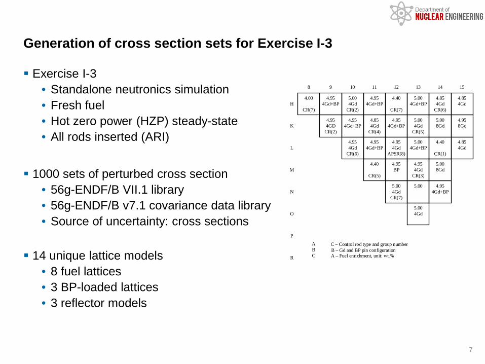
Exercise I-3 • Standalone neutronics simulation• Fresh fuel• Hot zero power (HZP) steady-state• All rods inserted (ARI)
1000 sets of perturbed cross section• 56g-ENDF/B VII.1 library• 56g-ENDF/B v7.1 covariance data library• Source of uncertainty: cross sections
14 unique lattice models• 8 fuel lattices• 3 BP-loaded lattices• 3 reflector models
Generation of cross section sets for Exercise I-3
7

SCALE 6.2 Sampler/Polaris• Sampler: General stochastic sampling method for uncertainty propagation• Polaris: new LWR lattice physics transport code
GenPMAXS: Conversion of format from txtfile16 to PMAXS PARCS: Nodal core simulator
Stochastic sampling using Sampler/Polaris and PARCS
8

For all fuel assembly lattices, the uncertainty of kinf is ~0.55% or ~600 pcm for fresh fuel.
Exercise I-3: lattice calculation
9
Lattice type kinf ± rel. σE4.00 1.12780 ± 0.55%E4.40 1.15704 ± 0.54%E4.85+4GD 1.15748 ± 0.54%E4.95+BP 1.06570 ± 0.55%E4.95+BP+4GD 1.03814 ± 0.56%E4.95+4GD 1.16358 ± 0.53%E4.95+8GD 1.13113 ± 0.54%E5.00 1.19453 ± 0.53%E5.00+BP+4GD 1.04129 ± 0.56%E5.00+4GD 1.16657 ± 0.53%E5.00+8GD 1.13422 ± 0.54%

2-group cross sections generated for 1 nominal + 1000 samples Core condition: fresh, HZP, ARI Running mean and uncertainty do not change much when N > 400 The standard deviation of k-eff with 1000 and 150 samples are both ~0.51%
Exercise I-3: running mean k-eff
10
Nominal keff 1.00361
Sample mean keff ± rel. σ(1000 samples) 1.00340 ± 0.51%
Sample mean keff ± rel. σ(150 samples) 1.00374 ± 0.51%
Diff. from nominal keff 0.01%
Diff. from mean keff of 1000 samples 0.03%

But a larger sample size will yield narrower confident intervals* A sample size of 100 yields >10% relative confidence interval It is not acceptable if N = 100 is used to investigate some effect that has < 10%
impact on sample standard deviation
Confidence intervals for k-eff population standard deviation
11
𝑁𝑁 − 1𝜒𝜒 ⁄𝛼𝛼 2,𝑁𝑁−12 − 100%
𝑁𝑁 − 1𝜒𝜒 1− ⁄𝛼𝛼 2,𝑁𝑁−12 − 100%
Evolution of 95% relative confidence intervals with sample size
Sample size N lower limit upper limit
100 87.8% 116.2%
500 94.2% 106.6%
1000 95.8% 104.6%
Relative confidence interval for confidence level of 95%
How to choose sample size N?• Depends on users’ need
• CL/confidence interval• Convergence of std
• Depends on response of interest• Is it possible to let Sampler
choose N?
* F. Bostelmann et al., "Some comments on the GRS MHTGR results of Phase I,", IAEA CRP on HTGR UAM: RCM-4, Vienna, May 22-25, 2017

Exercise I-3: axial power profile
12
Slightly top half peaked
87% - node 9
13% - node 10
Axial peaking location
Nominal FZ: 1.487Sampled FZ fixed location (node 9): 1.487 ± 0.14%Sampled FZ location free: 1.487 ± 0.16%
Exercise I-3: radial power profile
13
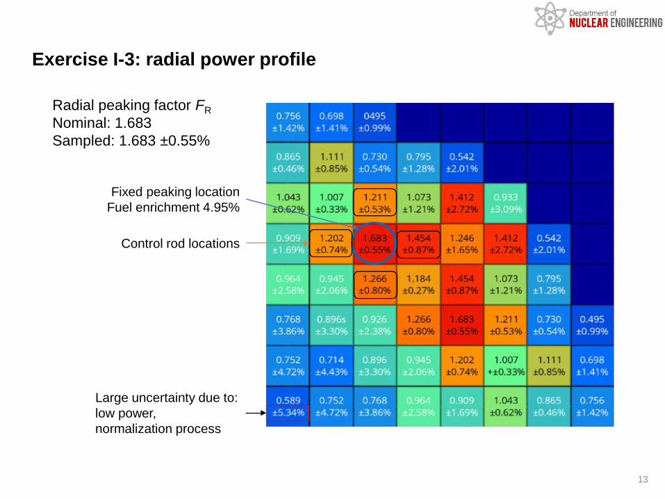
Fixed peaking locationFuel enrichment 4.95%
Control rod locations
Radial peaking factor FRNominal: 1.683Sampled: 1.683 ±0.55%
Large uncertainty due to:low power,normalization process

Ex III-1: core condition and exposure map available
Currently only focusing on steady state neutronics calculation HFP condition
• Reactor power = 100% rated power (2771.9 MW);• Average fuel temperature = 921 K, inlet moderator temperature = 562.67 K, outlet
moderator temperature = 592.7 K; • Control rod groups 1–6 completely withdrawn, group 7 completely inserted and group 8
(APSR) 53.8% inserted;• Core inlet pressure = 15.36 MPa;• Core flow rate = 16546.04 kg/s.
EOC assembly burnup map
• HZP condition• Fuel temperature = 551 K, moderator
temperature = 551 K and moderator density = 766 kg/m3;
• Control rod groups 1–4 completely withdrawn, groups 5–7 completely inserted and group 8 (APSR) 70% inserted.
14

Same approach as in Ex I-3: Polaris/Sampler State variables: fuel temperature, coolant density, and control rod insertion. Boron concentration fixed at 1935 ppm and 5 ppm for BOC and EOC, respectively.
Parameterized cross section generation: range of state variables
15
State variables State points calculated
Fuel temperature (K) 551, 921, 1780, 2400, 3000
Boron Concentration (ppm) 5, 1935
Coolant density (g/cc) 0.660, 0.702, 0.733, 0.770
Control rod insertion Yes, no
APSR insertion Yes, no
For non-APSR assemblies: 5×4×2=40 state points for both BOC and EOC state
Ref state CR branch
DC branch
TF branch
PC = 1935 ppm
PC = 5 ppm
For APSR lattice: 5×4×4=80 state points for both BOC and EOC state, respectively.
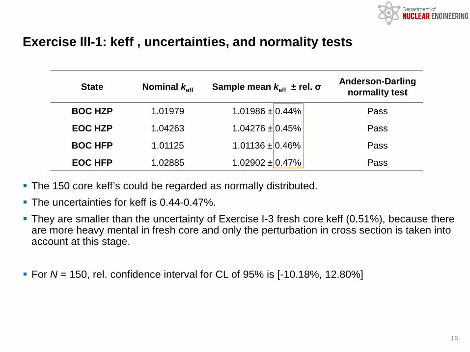
The 150 core keff’s could be regarded as normally distributed. The uncertainties for keff is 0.44-0.47%. They are smaller than the uncertainty of Exercise I-3 fresh core keff (0.51%), because there
are more heavy mental in fresh core and only the perturbation in cross section is taken into account at this stage.
For N = 150, rel. confidence interval for CL of 95% is [-10.18%, 12.80%]
Exercise III-1: keff , uncertainties, and normality tests
16
State Nominal keff Sample mean keff ± rel. σ Anderson-Darling normality test
BOC HZP 1.01979 1.01986 ± 0.44% Pass
EOC HZP 1.04263 1.04276 ± 0.45% Pass
BOC HFP 1.01125 1.01136 ± 0.46% Pass
EOC HFP 1.02885 1.02902 ± 0.47% Pass
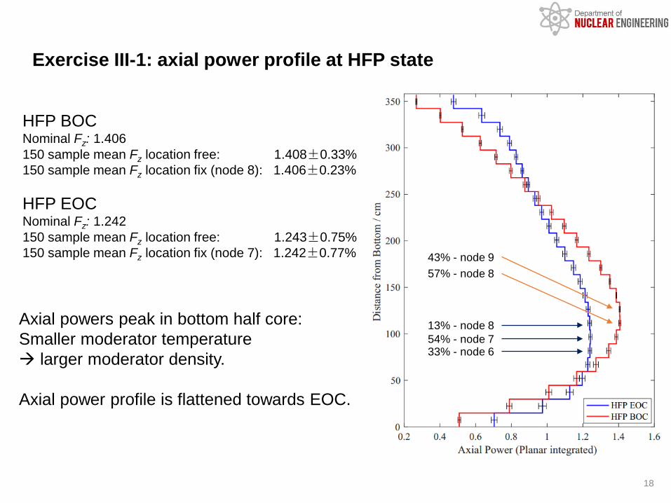
Exercise III-1: axial power profile at HFP state
18
HFP BOCNominal Fz: 1.406150 sample mean Fz location free: 1.408±0.33%150 sample mean Fz location fix (node 8): 1.406±0.23%
HFP EOCNominal Fz: 1.242150 sample mean Fz location free: 1.243±0.75%150 sample mean Fz location fix (node 7): 1.242±0.77%
Axial powers peak in bottom half core:Smaller moderator temperature larger moderator density.
Axial power profile is flattened towards EOC.
57% - node 843% - node 9
54% - node 733% - node 6
13% - node 8

Exercise III-1: radial power distribution at HFP
20
Uncertainty smaller at EOC due to flattened flux distribution
HFP EOC HFP BOC
51% L9peaking location
49% M10 100% L9peaking location

Exercise III-1: radial power distribution at BOC
21
HZP BOC HFP BOC
Control rod bank 6Control rod bank 5

Summary on LWR UAM activities
Cross section sets prepared for TMI-1 case in NEMTAB and PMAX format using Polaris/Sampler in SCALE 6.2.1 Preliminary results obtained for TMI-1 steady-state simulations using statistical
sampling method• Core keff, axial power peaking factor and radial power peaking factor are
analyzed with associated uncertainties• Anderson-Darling normality test performed
23
Ongoing work• It was reported that pin-by-pin calculation
yields a non-normal power peaking factors. In contrast, the nodal solution of the power peaking factors are normally distributed.
• Continue with depletion and transient (REA) simulations
Capability needed• Shape function
generated by Polaris
• Now available inNEWT output

24
IAEA CRP on HTGR UAM:PBR-250
Lidong Wang, Fu LiInstitute of Nuclear and New Energy Technology (INET)Tsinghua University, China
Jason Hou, Kostadin IvanovDepartment of Nuclear EngineeringNorth Carolina State University
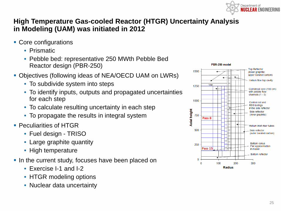
Core configurations• Prismatic• Pebble bed: representative 250 MWth Pebble Bed
Reactor design (PBR-250) Objectives (following ideas of NEA/OECD UAM on LWRs)
• To subdivide system into steps• To identify inputs, outputs and propagated uncertainties
for each step• To calculate resulting uncertainty in each step• To propagate the results in integral system
Peculiarities of HTGR• Fuel design - TRISO• Large graphite quantity• High temperature
In the current study, focuses have been placed on• Exercise I-1 and I-2• HTGR modeling options• Nuclear data uncertainty
High Temperature Gas-cooled Reactor (HTGR) Uncertainty Analysis in Modeling (UAM) was initiated in 2012
25
SCALE versions• 6.1, 6.2, 6.2.2
SCALE modules• KENO-VI, TSUNAMI-3D
SCALE libraries• Nuclear data libraries: ENDF/B VII.0, ENDF/B VII.1• Covariance libraries: 44groupcov, 56groupcov7.1
SCALE modules used in this study
26
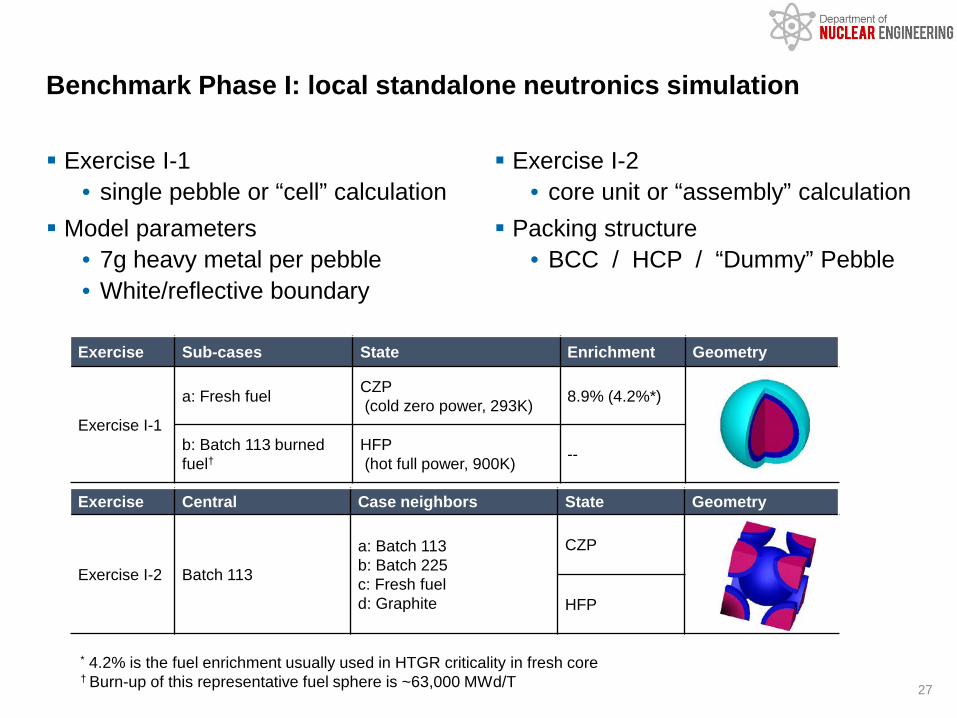
Exercise I-1• single pebble or “cell” calculation
Model parameters• 7g heavy metal per pebble• White/reflective boundary
Exercise I-2• core unit or “assembly” calculation
Packing structure• BCC / HCP / “Dummy” Pebble
Benchmark Phase I: local standalone neutronics simulation
27
Exercise Sub-cases State Enrichment Geometry
Exercise I-1
a: Fresh fuel CZP(cold zero power, 293K) 8.9% (4.2%*)
b: Batch 113 burned fuel†
HFP(hot full power, 900K) --
Exercise Central Case neighbors State Geometry
Exercise I-2 Batch 113
a: Batch 113b: Batch 225c: Fresh fueld: Graphite
CZP
HFP
* 4.2% is the fuel enrichment usually used in HTGR criticality in fresh core† Burn-up of this representative fuel sphere is ~63,000 MWd/T

Modeling approaches (Ex I-1a only)• Various levels of geometry simplification• Effect on multiplication factor
Effect of ND library (Ex I-1a, CZP & HFP state) Uncertainty quantification
Modeling with KENO-VI• Explicit model of coated particles (lattice)• Homogenized fuel region with • DOUBLEHET unit cell• Homogenized fuel region with RPT
Modeling with Serpent-2• Randomly distributed particles• Code-to-code verification
Exercise I-1: single pebble
28
lattice
homogenizedRPT*
random(Serpent-2)
homogenizedDOUBLEHET

Ex I-1a, ENDF/B VII.1
Effect of modeling approaches on multiplication factors
29
CaseCZP (293K) HFP (900K)
keff±σ Δ[pcm] keff±σ Δ[pcm]
KENO-VI CE Lattice 1.57841±0.00019 reference 1.50277±0.00014 reference
Serpent-2 Lattice 1.57883±0.00010 42 1.50298±0.00010 21
Serpent-2 Random 1.57656±0.00010 -185 1.50071±0.00010 -206
KENO-VI MG DH 1.57535±0.00015 -306 1.49904±0.00014 -373
Serpent-2 HM 1.46188±0.00008 -11,653 1.37548±0.00010 -12,729KENO-VI CE HM 1.46131±0.00014 -57 1.37559±0.00015 11
KENO-VI MG HM 1.45914±0.00021 -274 1.37378±0.00025 -170
• CE Monte Carlo methods produce consistent results using lattice model: Δk < 50 pcm• Results associated with random distribution of particles are in between those of lattice
and DH models• CE Lattice model vs. MG DOUBLEHET model: -306 & -373 pcm
With double heterogeneity treatment
Approximate homogenization

Multiplication factor
Effect of nuclear data libraries (Ex I-1a, 8.9% enrichment)
30
CaseCZP(293K) HFP(900K)
ENDF/B VII.0 ENDF/B VII.1 Δ[pcm] ENDF/B VII.0 ENDF/B VII.1 Δ[pcm]
KENO-VI CE Lattice 1.58613±0.00019 1.57841±0.00019 772 1.50948±0.00013 1.50277±0.00014 671
Serpent-2 Lattice 1.58580±0.00010 1.57883±0.00010 697 1.50932±0.00010 1.50298±0.00010 634
Serpent-2 Random 1.58379±0.00010 1.57656±0.00010 723 1.50717±0.00010 1.50071±0.00010 646
KENO-VI MG DH 1.58309±0.00016 1.57535±0.00015 774 1.50694±0.00013 1.49904±0.00014 790
Serpent-2 HM 1.46737±0.00008 1.46188±0.00008 549 1.38110±0.00010 1.37548±0.00010 562
KENO-VI CE HM 1.46763±0.00015 1.46131±0.00014 632 1.38176±0.00016 1.37559±0.00015 617
KENO-VI MG HM 1.46589±0.00021 1.45914±0.00021 675 1.37954±0.00020 1.37378±0.00025 576
• 500-800 pcm difference was found when comparing the results of ENDF/B VII.0 and ENDF/B VII.1 for all models at both CZP and HFP states.
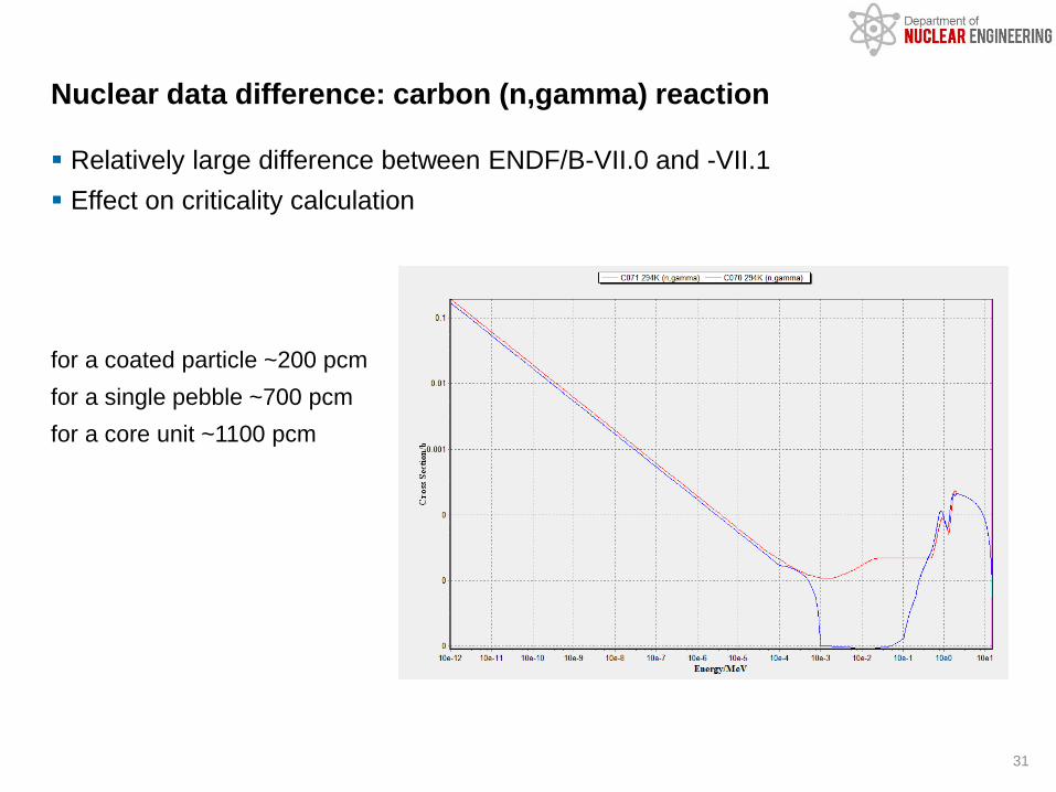
Relatively large difference between ENDF/B-VII.0 and -VII.1 Effect on criticality calculation
for a coated particle ~200 pcmfor a single pebble ~700 pcmfor a core unit ~1100 pcm
Nuclear data difference: carbon (n,gamma) reaction
31

Various options in TSUNAMI-3D were tested• MG: the doubly heterogeneous effect cannot be ignored• CE-IFP*: huge memory footprint• CE-CLUTCH†: mesh grid with enough neutron histories is required
• Convergence of importance function F*(r) should be guaranteed• Choice of mesh size and neutron history in each mesh is important but
heavily relies on user’s experience • Sensitivity coefficients obtained from TSUNAMI-3D should always be
verified with direct perturbation method (DPM) results. Calculations performed for the following
• MG/CE TSUNAMI-3D (Ex I-1a)• CE TSUNAMI-3D (Ex I-1b)• Parametric study for CE-CLUTCH• Influence of temperature• Influence of covariance libraries
Uncertainty quantification (UQ) following sensitivity based approach
32
* Iterated Fission Probability† Contribution-linked Eigenvalue Sensitivity/Uncertainty Estimation via Tracklength Importance Characterization

Related issues• COV-Lib couldn’t be switched to 44groupcov in CE TSUNAMI-3D sequence –
resolved in SCALE 6.2.2• MG mode with Doublehet option succeed, which was unexpected
Ex I-1a (fresh fuel) CZP state results
MG/CE TSUNAMI-3D calculations (SCALE6.2, Ex I-1a)
33
TSUNAMI ND_Lib COV_Lib keff Uncertainty (%k/k)
MGENDF/B
VII.0
44groupcov 1.58309±0.00016 0.455390±0.00004056groupcov7.1 1.58309±0.00016 0.497242±0.000016
CE-IFP 56groupcov7.1 1.58553±0.00039 0.500800±0.000430CE-CLUTCH 56groupcov7.1 1.58580±0.00022 0.500440±0.000380
MGENDF/B
VII.1
44groupcov 1.57586±0.00015 0.454402±0.00004056groupcov7.1 1.57586±0.00015 0.493352±0.000020
CE-IFP 56groupcov7.1 1.57970±0.00040 0.503500±0.000480CE-CLUTCH 56groupcov7.1 1.57975±0.00014 0.502950±0.000250
Should always use consistent ND and COV libraries: ENDF/B-VII.0+44groupconv; ENDF/B-VII.0+56groupconv7.1
MG TSUNAMI-3D UQ results are smaller than CE TSUNAMI-3D UQ results, as the implicit effect is ignored.
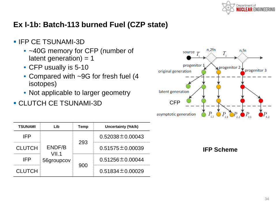
IFP CE TSUNAMI-3D• ~40G memory for CFP (number of
latent generation) = 1• CFP usually is 5-10• Compared with ~9G for fresh fuel (4
isotopes)• Not applicable to larger geometry
CLUTCH CE TSUNAMI-3D
Ex I-1b: Batch-113 burned Fuel (CZP state)
34
CFP
IFP Scheme
TSUNAMI Lib Temp Uncertainty (%k/k)
IFP
ENDF/B VII.1
56groupcov
2930.52038±0.00043
CLUTCH 0.51575±0.00039
IFP900
0.51256±0.00044
CLUTCH 0.51834±0.00029

IFP results were collected in test calculations that didn’t follow recommended setup
Influence of temperature on uncertainties
35
Exercise TSUNAMI Lib Temp k-eff Uncertainty (%k/k)
Ex I-1aIFP
ENDF/B VII.1
56groupcov
293K 1.57965±0.00029 0.50130±0.00032
900K 1.50402±0.00030 0.51565±0.00038
CLUTCH293K 1.57975±0.00014 0.50295±0.00025
900K 1.50337±0.00014 0.51834±0.00029
Ex I-1bIFP
293K 1.09173±0.00015 0.51575±0.00039
900K 1.05889±0.00043 0.51472±0.00064
CLUTCH293K 1.09193±0.00020 0.52038±0.00043
900K 1.05908±0.00016 0.51258±0.00044
Sensitivity analysis is required to understand the decrease of rel. uncertainty with temperature for burned fuel.
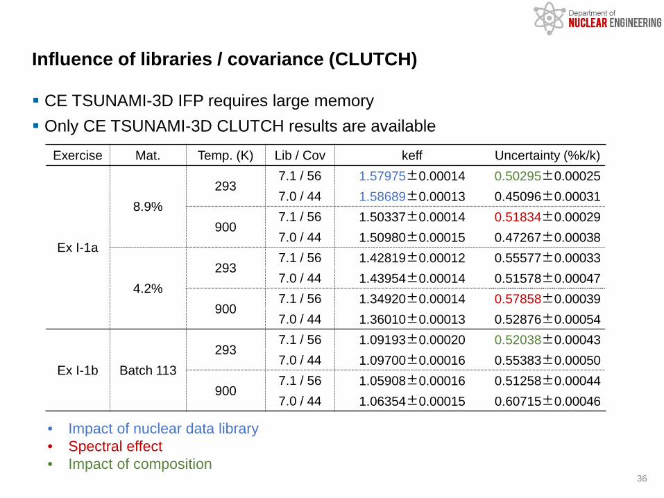
CE TSUNAMI-3D IFP requires large memory Only CE TSUNAMI-3D CLUTCH results are available
Influence of libraries / covariance (CLUTCH)
Exercise Mat. Temp. (K) Lib / Cov keff Uncertainty (%k/k)
Ex I-1a
8.9%293
7.1 / 56 1.57975±0.00014 0.50295±0.000257.0 / 44 1.58689±0.00013 0.45096±0.00031
9007.1 / 56 1.50337±0.00014 0.51834±0.000297.0 / 44 1.50980±0.00015 0.47267±0.00038
4.2%293
7.1 / 56 1.42819±0.00012 0.55577±0.000337.0 / 44 1.43954±0.00014 0.51578±0.00047
9007.1 / 56 1.34920±0.00014 0.57858±0.000397.0 / 44 1.36010±0.00013 0.52876±0.00054
Ex I-1b Batch 113293
7.1 / 56 1.09193±0.00020 0.52038±0.000437.0 / 44 1.09700±0.00016 0.55383±0.00050
9007.1 / 56 1.05908±0.00016 0.51258±0.000447.0 / 44 1.06354±0.00015 0.60715±0.00046
36
• Impact of nuclear data library• Spectral effect• Impact of composition

Impact of fuel enrichment Results obtained for ENDF/B-VII.1 + 56g cov Spectral shift affects contribution to k-eff uncertainty
Top 7 Contributors to keff Uncertainty
37
No.8.9%wt 4.2%wt
Matrix Contribution Matrix Contribution
1 U-235 �̅�𝜈 3.7866E-01 U-235 �̅�𝜈 3.8136E-01
2 U-235 (𝑛𝑛, 𝛾𝛾) 2.0919E-01 U-238 (𝑛𝑛, 𝛾𝛾) 2.2987E-01
3 U-238 (𝑛𝑛, 𝛾𝛾) 1.6196E-01 U-235 (𝑛𝑛, 𝛾𝛾) 1.9664E-01
4 U-235 𝑛𝑛, 𝑓𝑓 (𝑛𝑛, 𝛾𝛾) 1.0949E-01 Graphite (𝑛𝑛, 𝛾𝛾) 1.7274E-01
5 Graphite (𝑛𝑛, 𝛾𝛾) 9.0193E-02 U-235 𝑛𝑛, 𝑓𝑓 (𝑛𝑛, 𝛾𝛾) 1.2147E-016 Grphite (𝑛𝑛,𝑛𝑛) 8.2684E-02 U-235 (𝑛𝑛,𝑓𝑓) 9.3696E-02
7 U-235 (𝑛𝑛,𝑓𝑓) 7.1330E-02 Grphite (𝑛𝑛,𝑛𝑛) 7.6731E-02
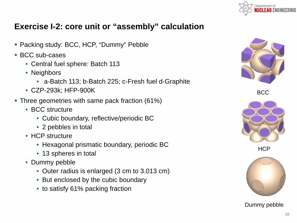
Packing study: BCC, HCP, “Dummy” Pebble BCC sub-cases
• Central fuel sphere: Batch 113 • Neighbors
• a-Batch 113; b-Batch 225; c-Fresh fuel d-Graphite• CZP-293k; HFP-900K
Three geometries with same pack fraction (61%)• BCC structure
• Cubic boundary, reflective/periodic BC• 2 pebbles in total
• HCP structure• Hexagonal prismatic boundary, periodic BC• 13 spheres in total
• Dummy pebble• Outer radius is enlarged (3 cm to 3.013 cm)• But enclosed by the cubic boundary• to satisfy 61% packing fraction
Exercise I-2: core unit or “assembly” calculation
38
BCC
HCP
Dummy pebble

Multiplication factor ENDF/B VII.1, CZP, all 4.2% enrichment• Impact of geometry is negligible as long as the pack fraction is maintained
UQ using TSUNAMI-3D CLUTCH for BCC sub-cases• Central pebble is batch 113 burned fuel sphere
Criticality calculation and UQ results
Model BCC HCP Dummy pebble
KENO-VI CE Lattice 1.42787±0.00014 1.42811±0.00015 1.42835±0.00014
Serpent-2 Lattice 1.42789±0.00008 1.42810±0.00008 1.42817±0.00008
Serpent-2 Random 1.42639±0.00008 1.42641±0.00008 1.42681±0.00008
KENO-VI MG DH 1.42547±0.00011 1.42540±0.00012 1.42560±0.00011
39
Sub-casesCZP HFP
keff Uncertainty % keff Uncertainty %
a: batch 113 1.09163±0.00015 0.48780±0.00032 1.05913±0.00014 0.50412±0.00041
b: batch 225 0.99503±0.00016 0.54570±0.00050 0.98523±0.00014 0.54084±0.00045
c: fresh fuel 1.35637±0.00017 0.48444±0.00027 1.28407±0.00014 0.48116±0.00032
d: graphite 1.16663±0.00015 0.54910±0.00035 1.16906±0.00015 0.51635±0.00042
Absolute uncertainties are similar
Absolute uncertainties larger due to graphite contribution

Exercise I-1 single pebble• Study on modeling approaches (only for Ex I-1a)
• Various levels of geometry simplification• Effect on multiplication factor (CZP & HFP state)
• Effect of ND and COV library (CZP & HFP state)• Uncertainty quantification
Exercise I-2 core unit• Packing study• Uncertainty quantification
Ongoing work• PBR-250 whole-core model• UQ using CE TSUNAMI-3D CLUTCH• Not possible without MPI support
Summary on HTGR CRP activities
40
Detailed instructionfor compiling SCALE with MPI support is needed
Parallel SCALE (with MPI support)cp script/configure_scale_mpi.sh build/gccchmod u+x build/gcc/configure_scale_mpi.sh./configure_scale_mpi.sh ../..

NCSU is performing studies on a number of Uncertainty Analysis in Modeling (UAM) benchmarks
• NEA/OECD Light Water Reactor (LWR) UAM• IAEA CRP High Temperature Gas-cooled Reactor (HTGR) UAM• NEA/OECD Sodium-cooled Fast Reactor (LWR) UAM
SCALE package is one of the major computational tools adapted for the benchmark specification and calculations
• Neutronics modeling • Sensitivity and uncertainty (S/U) analysis• SCALE 6.2/6.2.1/6.2.2• TSUNAMI, Polaris, Sampler, KENO, etc.
Summary
41