unclassified arh-470 this document classified by m. h
TRANSCRIPT

UNCLASSIFIED ARH-470
This document classified by M. H. Curtis
LABORATORY STUDIES OF MIXED-OXIDE POWDER PREPARATION BY CONTINUOUS AMMONIA PRECIPITATION
By
M. H. Curtis
Plutonium Chemistry Laboratory Research and Engineering
Chemical Processing Division
April 1, 1968
ATLANTIC RICHFIELD 'HANFORD COMPANY RICHLAND; WASHINGTON
Operated for the Atomic Energy Commission by Atlantic Richfield Hanford Company under Contract #AT(45-1)2130
tJNCLASSIFIED

DISCLAIMER
This report was prepared as an account of work sponsored by an agency of the United States Government. Neither the United States Government nor any agency Thereof, nor any of their employees, makes any warranty, express or implied, or assumes any legal liability or responsibility for the accuracy, completeness, or usefulness of any information, apparatus, product, or process disclosed, or represents that its use would not infringe privately owned rights. Reference herein to any specific commercial product, process, or service by trade name, trademark, manufacturer, or otherwise does not necessarily constitute or imply its endorsement, recommendation, or favoring by the United States Government or any agency thereof. The views and opinions of authors expressed herein do not necessarily state or reflect those of the United States Government or any agency thereof.

DISCLAIMER Portions of this document may be illegible in electronic image products. Images are produced from the best available original document.

ARH-470
TABLE OF CONTENTS
Page
I. INTRODUCTION 1
II. SUMMARY AND CONCLUSIONS 4
III. BACKGROUND 5
A. Flow Sheet And Chemistry 5
B. Previous Work 6
C. Product Properties 9
IV. EXPERIMENTAL WORK 10
A. Small-Scale Studies 10 B. Prototype Precipitation And Drum Filter
Rxins 11 C. Prototype Vibrating Tube Hydrogen Reducer
Runs 15
V. DISCUSSION 17
A. Continuous Precipitation-Filtration . . . 17 B. Continuous Hydrogen Reduction 20
C. Other Processing Considerations 22
VI. RECOMMENDATIONS 24
VII. ACKNOWLEDGMENTS 26
VIII. REFERENCES 26
IX. APPENDICES 29
A. Vallecitos Preparation Of Mixed Oxide . . 29
B. NUMEC Mixed Oxide Preparation 30
C. DuPont Flow Sheet For Mixed Oxide Powders. 31
D. Small-Scale Batch Run Results 32

1 ARH-470
LABORATORY STUDIES OF MIXED-OXIDE POWDER
PREPARATION BY CONTINUOUS AMMONIA PRECIPITATION
I. INTRODUCTION
The nuclear power industry is growing toward fast reactor
concepts using mixed plutonium-uranium fuels. The mixed
oxides are currently the most favored of these fuels. How
ever, for fast reactor fuel the oxides must be uniform, mixed
crystals instead of a mixture of oxides (which may be used in
thermal reactors such as PRTR).
The APED of General Electric specifies fuel elements for
the SEFOR reactor be prepared from ammonia-coprecipitated
uranium plutonium oxides which have been pressed into pellets
and loaded into tubes. Test fuel elements have been prepared
by their Vallecitos Laboratory using batch techniques.
The potential of using existing Plutonium Finishing equip
ment and preparing coprecipitated mixed crystal oxides on a
continuous basis offers a way to diversify ARHCO's Plutonium
production capabilities. The parallel processing require
ments of a plutonixim button line and a continuous-mixed oxide
precipitation facility are shown in Figure 1. A simplified
flow diagram (Figure 2) shows the relation of these oxide
powder preparation ope4:ations to the fuel element production
process.
Recently a problem has arisen on the shipping of plutonium
nitrate for use in mixed oxide fuels. Radiolysis of the solu
tion (plus valence state changes) has led to gas pressure
problems in making the shipments. The customers obviously do
not want to receive the simpler-to-ship plutonium oxide be
cause the dissolving of plutonixim oxide introduces unwanted
fluoride or other impurities. However, if true mixed crystal
uranium-plutonium oxides as a "master mix" were shipped, these

ARH-470
Pu(N03 X H^Os PKTOIE'ld
BIETON Ulffi FTA3¥ SHEET
Feed Ta-Tdk
Oxali: Acid X Precipitator
+ CO.
Screw Calciner
350 °C
Acidi? F i l t r a t e to Recovery ( i jnpmlt les)
/ I
HF+Og+HsO
HF.+ 0=
Yilsrating Tube Pluorinator
500 °C
V PuF,
Precipitate:
CCPKECIPITATED OXIDE FLOW SHSET
Basic, Filtrate to Discard (imptirities)
_1 Hydrogen Reduction T50 *C
U«Pu(0)2
FIGURE 1
PARALLEL PROCESSING REQUIREMENTS

Pu(N0d)4
C\ urn
11H4OH M.
t F i l t r a t e
FIGURE 2 -i
S I M P L I F I E D FLOW biAGRAM MIXED OXIDE FUEL
ELEMENT PRODUCTION
Inspect P e l l e t s
PU(0H)4 + ADU
Sinter 1600 °C w^
Inspect Elements
Inspect Assemblies
Gases
u>
• ^ I p J
>
I •J o
4 ARH-470 I
could be readily dissolved and blended in as feed for the
customer's oxide production facility.
The work covered by this report is devoted to studies on
the continuous coprecipitation of uranium diuranate-plutonium
hydroxide by ammonia of a product which would meet the powder
quality specifications. The goal was twofold: (1) to achieve
a high filtration rate for the slurry (relative to plutonium
oxalate, and in the same type of continuous precipitator) on
a vacuum drum filter; and (2) to achieve satisfactory hydrogen
reduction in a continuous vibrating tube reactor so as to give
acceptable powder properties.
This experimental study was limited to the data of im
mediate interest for continuous processing by the ammonium pre
cipitation route. It is further limited to those processes
that might be performed in available equipment. It does not ex
tend beyond the powder preparation step. The work was done
with a nominal composition of 15% plutonium-85% uranium.
II. SUMMARY AND CONCLUSIONS
Experimental work in laboratory and prototype equipment
has established that the existing Plutonixim Finishing equip
ment has the potential of producing mixed oxides by the am
monia coprecipitation process.
Continuous precipitation of a slurry suitable as feed for
a continuous drxim filter is possible by using close pH control
and elevated temperature. A throughput up to the plutonixim
oxalate filtration rate may be obtained (actinide weight
basis).
Continuous hydrogen reduction may be achieved in a vi
brating tube reactor if the equipment is capable of providing
suitable temperatures, gas flow rates, and residence times.
The actinide throughput capability has not been determined for
the plutonixim vibrating tube fluorinator.
5 ARH-470
By following the techniques developed in this work, the
product oxide physical and chemical properties are suitable
for fuel fabrication; the pelletizing characteristics were
not measured, however.
Additional work needs to be done on the pelletizing char
acteristics of the mixed oxide powders and the demonstration
of a suitable dryer-solids conveyor, such as the plutonixim
oxalate screw calciner.
III. BACKGROUND
A. Flow Sheet And Chemistry
The overall flow sheet for producing fast reactor fuel
elements using mixed-crystal uranixim-plutonixim oxide pellets
is shown in Figure 2, page 3. The major portion of this re
port is devoted to those chemical processes for producing the
oxide powders required for pellet fabrication.
The basic process for preparing mixed crystal oxides by (1 2)
ammonia precipitation was demonstrated over a decade ago. ' (3-5)
More recently it has been studied further, and test fuel
elements have been fabricated by this technique for reactors
such as SEFOR (Southwest Experimental Fast Oxide Reactor). The following are the simplified chemical reactions in-
(1) volved.
[UNH] [ADU] 2U02(N03)2 + 6NH3 + 2H2O -> (NH^)2U20^ + 4NH^N02
Pu(N02)4 + 4NH2 + 4H2O Pu(OH)^ + 4NH^N02
(NH^)2U20^ + 2H2 2UO2 + 3NH2 + 3H2O
Pu(OH) ^ PUO2 + 2H2O
The chemistry, however, for the ADU (ammonixim diuranate)
precipitation from UNH (uranyl nitrate hexahydrate) is not that
simple. A study of the chemistry was required to convert batch

6 ARH-470
precipitation technology for a mixed crystal product to a
continuous precipitation-continuous filtration technology
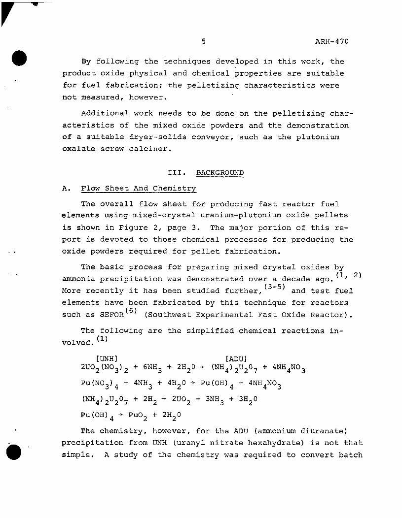
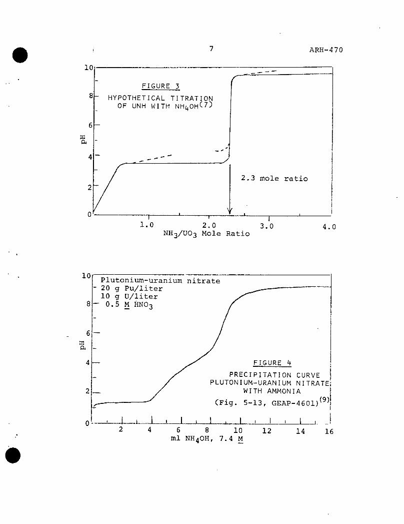
needed for production of the sinterable mixed oxides. Fig-(7)
ure 3 shows the uranixun system chemistry involved: this chemistry formed the basis of a continuous ammonia-uranixim
(8) precipitation technique developed in the laboratory based on pH control.
A curve of the uranixim-plutonixim n i t r a t e t i t r a t i o n with (9)
ammionixim hydroxide is shown in Figure 4. This curve is similar to the curve obtained when ammonixim hydroxide was
(8)
titrated into a U(VI)-U(IV) chloride solution. Companion
curves are shown in Figures 5 and 6. The uranyl nitrate pre
cipitation curve (Figure 5) shows the uranixim precipitation
occurs between pH 3.0 and pH 4.0. Precipitation is shown in
Figure 6 to occur in the region of pH 1.0 in a plutonixim ni
trate system. B. Previous Work
The General Electric Vallecitos Laboratory (APED) has pre
pared mixed oxides on a batch basis limited to a few hundred
grams per batch. The Nuclear Materials and Equipment Corpora
tion (NUMEC) has done considerable work with a continuous
precipitation-batch filtration process which has been limited
to slightly over 1 kg of actinides per batch. DuPont has pro-(5)
posed a plant for mixed oxide fuel preparations, but the
technical basis for their assumptions are not clear. The
Appendices give typical mixed oxide preparation conditions for
GE-APED, NUMEC, and duPont. The English have described a full-scale plant based on
desc, (11)
Most workers appear to have gone from uranixim oxide fuel (12) concepts to the mixed oxide concept m their engineering
of fuel preparation. Since there is ample experience with
continuous processing. Their process is described as
being a "multi-stage feedback precipitation".
ARH-470
10
FIGURE 5
HYPOTHETICAL TITRATION OF UNH WITH NHi OH' 7)
y
2.3 mole ratio
1.0 2,0 3.0 NH3/UO3 Mole Ratio
4.0
10
8
Plu ton ix im-uran ium n i t r a t e - 20 g P u / l i t e r
10 g U / l i t e r 0 .5 M HNO-3
FIGURE h
PRECIPITATION CURVE PLUTONIUM-URANIUM NITRATE
WITH AMMONIA
,(9) (Fig. 5-13, GEAP-4601)
1 L 6 8 10
ml NH4OH, 7.4 M 12 14 16

8
10 Uranyl nitrate 100 g U/liter 1 M HNO-
FIGURE 5
PRECIPITATION CURVE URANYL NITRATE-AMMONIA SYSTEM
(Fig. 5-14, GEAP-4601) (
J I JL. 28
X._i. 20 24 28 32 ml NH4OH, 7.4 M
36 40
Plutonixim nitrate 100 g Pu/liter 1.12 M HNO3
FIGURE 6
PRECIPITATION CURVE PLUTONIUM NITRATE-AMMONIA SYSTEM
(Fig. 5-15, GEAP-4601) ^
10 20 ml NH4OH,
9 ARH-470
(13) production of enriched uranixim oxide fuel fabrication
with its processing concepts similarly limited by critical
mass limitations, the transition to plutonixim-bearing oxides
is not great.
C. Product Properties
Achieving a continuous process will be successful only if
it turns out a product that meets specific requirements.
Most important of these requirements is that the oxide is a
true mixed crystal with PxiO- in a lattice of UO2. The best
method currently known to determine this structure is by x-ray
diffraction of the crystals. While this method is subject to
interpretation, a "standard" may be easily obtained by using
the Vallecitos method of coprecipitation, which assures a
mixed crystal precipitation by rapidly going to pH 9.5. A
crude test involves dissolution in nitric acid—the true
mixed crystal dissolves rapidly and completely; but free PuO^
present does not dissolve.
The x-ray diffraction results are expressed as percent
"free" PuO^ in the mixed oxide. A value of <1% is the lower
limit of detection of both the method and the SEFOR specifica
tion.
Another property that is important is the oxygen-to-metal (14) (0/M) ratio. For powders this may be 2.0 to 2.3; but for
sintered pellets, it is controlled much closer (e.g., 198 +
0.01, or 2.01 + 0.001, etc.).
Ensuring the proper fuel properties has been based less
on powder properties than on the process used. The SEFOR
fuel process specification (ammonia coprecipitation) is based
on tests with fuel elements produced by that process. Properly
sintering to pellets is a criterion for powders for SEFOR-
type elements. A pellet press and a sintering furnace were
not available for evaluating the powders produced in this work.

10 ARH-470
The measure of the capability of a powder to form a sin
terable pellet is more difficult. However, conventional
powdei? analyses are used as controls; these include particle
size, ,'surface area, etc. Relationships of most of the meas
urable parameters have been developed through experience with
uranixim oxide fuels.
Other types of specifications may be considered. Two
specifications have been used at Hanford ' based on
processing rather than powder properties, as well as a speci-(17)
fircation for the powder. NUMEC characterizes their pow
ders by measurement of their properties.
To support these studies, it was necessary to set up
analytical methods. Those now available include x-ray dif
fraction, 0/M ratio, ' surface area, particle size,
moisture, and x-ray fluorescence.
IV. EXPERIMENTAL WORK
A. Small-Scale Studies
1. Technique
The preliminary precipitation work was done with small-
scale (5 to 10 g of actinides to a batch) runs, by the (8)
technique that has been detailed previously.
Hydrogen firing was performed after drying the filter
cakes at 100 to 150 °C in air. A quartz tube furnace
capable of holding three 10 g boats was used. Heating-up
was regulated to provide a 12 °C/min temperature increase.
The operating temperature (750 °C) was maintained for 6 hr.
The hydrogen was introduced as 6% H2-94% N_ at a rate of
3 ft /hr from the beginning of heating up until the system
cooled down after firing.
About 50 runs were made, primarily to demonstrate fil-
terability relationships, most of the resulting filter

11 ARH-470
cakes were dried and hydrogen-reduced to determine if the
precipitation technology yielded a true mixed crystal
pi?oduct.
' Selected runs are tabulated and their significance
pointed out in the Appendices.
The findings, in general, follow those found in the (8)
work on ADU precipitations and filterability.
For obtaining mixed crystals in the hydrogen-reduced
oxide, the region pH 4.5 to 5.5 was best; while a wider
range (pH 5.0 to 7.) was acceptable for filterability.
An elevated temperature (55 °C) is best for precipitation,
digestion, and filtration. From the standpoint of waste
losses, pH 5.0 was the lower limit to maintain low losses
and thus to maintain the desired ratio of plutonixim-
uranixim in the filtered solids.
On the basis of these small exploratory runs, a flow
sheet was drawn up to be used in the prototype runs. This
flow sheet is shown in Figure 7.
B. Prototype Precipitation And Drxim Filter Runs
1. Equipment (Figure 8)
The prototype precipitator was fabricated from a
10 3/4 in. long section of 4 in. schedule 40-type 304L SS
pipe. It had a rounded bottom and contained 1 5 liters
at overflow. A 1 1/3 in. steel tube was centrally posi
tioned in the vessel, and shrouded the agitator shaft and
solution entry lines. The agitator had a curved bottom
blade shaped to permit close sweeping of the vessel bot
tom, plus small paddles to provide agitation inside the
shroud tube. An air motor turned the agitator.
The precipitator vessel was externally heated by
two turns of a close-fitting "Calrod"*-type resistance
* Trade name. General Electric Company

12 ARH-470
FEED Actinides 100 g/ji HNO3 0.4 M 10 Vhr 55 °C
STRIKE HYDROXIDE 3M NH4OH 110 l/hr- (3 55
WASH HYDROXIDE 0.2M NH4OH 10 il/hr @ 55 °C
FILTRATES Actinides <0.01 g/Z H4NO3 39 g/i SH4OH 39 g/l (pH 9.0) 18 a/hr
FILTER CAKE PU(0HT4 193 g/hr (NH4)2U207 1114 g/hr H2O & NH3 1233 g/hr 2000 cc/hr
FIGURE 7
TYPICAL FLOW SHEET CONTINUOUS MIXED OXIDE PREPARATION
Basis: 15% Pu-85% U 1 kg actinides /hr
DRYING OFF-GAS S2O 1233 g/hr !JH3 @ 125 °C
DRIED CAKE PU(OHT Tn g/hr (NH4),0,07 1114 g/hr 110(5 cc/hr
REDUCTION GAS 8% H2-92% N2 100 i/min @ stp
750' ->{ REDUCTIO*
FIRE
REDUCTION OFF-GAS H^O 1M g/hr NH3 60 H2 27 N, 6.9 kg/hr 355 Jl/min @ 750 °C
MIXED OXIDES PUO2•UO2 1135 g/Er 500 cc/hr

Air Motor
Feed Line
Anunonia Line
Thermocouple Well
Slurry Overflow Tube
Shroud Tube
Agitator
Heating (?3> Coils < p ^
LU-
FIGURE 8
PROTOTYPE CONTINUOUS PRECIPITATOR AND FILTER
Wash Spray Filtrate Lines
To Vacuum Receiver
*-, Agitator Z< Drive
Scraper
/ /
DRUM FILTER
Side View
\
" \ *--_
Filter Pan
Agitator Blade
>
I

14 ARH-470
heater. A bracket at the vessel top supported a pH elec
trode and a thermocouple well outside the shroud tube.
Pjtf'ecipitator temperature regulation was by means of an
ON - OFF-type indicator-regulator using the thermocouple
to control the resistance heater.
The prototype filter was a 3 in. wide x 12 in. diam
filter drum. It was partially immersed in a pan shaped
to be coaxial with the drum, with a top that was 8 1/2 in.
wide and 17 3/4 in. long. The pan had a free volume of
1.3 liters. The drum was provided with a sliding valve
to program the vacuum from the waste receiver to the drum
segments for filtering, drying, and washing. Synthetic
fiber cloth was used as the filter media. An adjustable
scraper removed the slurry, and a chute directed it to a
receiver. The cake was sprayed with a wash solution after
leaving the filter pan and before reaching the scraper.
The drum and a reciprocating sweep agitator in the bottom
of the pan were driven by variable speed gear electric
motors.
Tankage for feed and waste receivers were in an ad
jacent hood; the tank for ammonium hydroxide was outside
the hood. Both feed and ammonium hydroxide were pumped at
variable speed and stroke by cam-driven piston pumps. A
portion of the feed line was equipped with an electrical
heating jacket to aid the temperature control in the pre
cipitator.
2. Procedure
Runs were limited by the available feed tank capacity—
about 10 liters. The precipitator was provided with suf-
fucient feed and ammonium hydroxide to provide an agitated
slurry for temperature and pH sensing. When the slurry
reached the proper temperature (55 °C), the feed and am
monium hydroxide pumping was started.

15 ARH-470 I
Feed rate was controlled to the limit of the filtra
tion capability. In some runs the feed was turned on and
off to match the filter capability; in other runs the
feed pumping rate was changed to match the filter capa
bility.
The ammonium hydroxide was pumped by a pximp head on
the same shaft as the feed pump. Early runs were made at
a fixed ratio of ammonium hydroxide-to-feed. In later
runs, the ammonium hydroxide flow was regulated by
throttling and by-passing the pump, to maintain pH control.
The filter drum variables of rate of rotation and
thickness of cake were adjusted, as required, to obtain
a maximum filtration rate. Usually one revolution per
minute provided the maximum filtration rate.
Prototype Vibrating Tube Hydrogen Reducer Runs
1. Equipment (Figure 9)
The prototype vibrating tube was formed out of 1 7/8 in.
ID Hastelloy C tube by flattening it to a 1 1/32 in. x
2 1/4 in. (inside) oval shape. The tube was oriented with
its major oval dimension horizontal. The tube was 41 3/4
in. long, with 32 in. of it heated by external resistance
furnaces. The entire furnace and tube assembly was mounted
on a variable incline bed that may be electromagnetically
vibrated. The tube ends were provided with flanges for
feed addition and product removal. The unheated portion
of the tube was provided with a top flange for off-gas
removal, while the gas inlet entry was made in the product
receiver attachment.
The incoming gases were preheated by routing them
through a resistance-heated section of piping and along
the length of the resistance filters of the vibrating tube.
A thermocouple well extended down the center of the vi
brating tube and three thermocouples, located at different

FIGURE 9
VIBRATING TUBE APPARATUS ASSEMBLY
T.C. Well
^^^=m
u
5" ?
a — U M
I Product Receiver Coupling
Side View-Sefction
Furnaces
t^ory
<T>
To Off-Gas Filter
r:r3.
itU
IxT Vibrating Tube
Screw Feed
JO w
-J
o

17 ARH-470
positions, gave data on the internal temperature of the
tube.
The feed mechanism was a variable speed, electric
motor-driven screw device fed by a funnel coupling to
glass feed jars; it vibrated with the tube to facilitate
powder flow. The off-gas was cleaned of powder by a
filter separate from the vibrating system before being
exhausted to the hood exhaust system. The product re
ceivers were glass jars.
Provision was made to time the frequency of the inter-
mittant vibrations. Both the vibration frequency and its
amplitude could be varied.
2. Procedure
The prototype vibrating-tube apparatus was used to
hydrogen-reduce the powders resulting from the vacuiom-
driam filter runs. The apparatus was adjusted (tube slope
and vibrating conditions) to give a 2-hr powder resi
dence time. The gas was an 8% H_-92% nitrogen mixture
which was metered into the apparatus under standard tem
perature and pressure conditions.
V. DISCUSSION
Continuous Precipitation-Filtration
1. Rates
A total of 9 significant runs were made in the proto
type precipitation-filtration apparatus. The essential
data from those runs are recorded in Table I.
This apparatus has a maximum demonstrated plutonium
oxalate processing rate of 7.5 g of Pu/min; the Table shows
the total actinide filtration rate relative to this value.
Runs which significantly exceeded pH 7 suffered in respect
to the filtration rate achieved.

n
1
2
3
4
5
6
7
8
9
0
Feed Temperature
Hot
Ambient
Ambient
Hot
Hot
Hot
Ambient
Hot
Hot
Hot
Feed Rate Regulation
Flow rate
on -
On -
Flow
Flow
On -
On -
Flow
On -
On -
off
off
rate
rate
off
off
rate
off
off
Ammoni K
N.A.
3
3
3
3
1
1
3
2
3
TABLE _I
PROTOTYPE DRUM FILTER
um Hydroxide Control
Flow ratio
Flow ratio
Flow ratio
Flow ratio
pH-bypass
pH-bypass
pH-bypass
pH-bypass
pH-bypass
pH-bypass
pH ^Range_
N.a.
4.0-10.0
2.1-9.5
3.7-7.4
4.6-5.2
4.8-8.8
3.7-5.9
3.7-7.8
2.4-9.3
5.2-8.2
RUNS
Run Duration
Hr
-
7
5
2.25
3
1.25
1.25
3.75
6
5.25
Average Filtratii Rate, g/m
N.A.
*2.7 (5.0
4.8
5.3
4.5
4.1
4.1
4.3
3. 2**
4.2
* Error in makeup, high in uranium. ** Low vacuum during this run.

19 ARH-470 I I
On the basis of the experience with these runs, it
was found that smoother operation was obtained when the
feed was preheated to 60 °C and the filter pan was main
tained at 45 °C. Adjustment of flow rates to maintain
a constant filter pan level, rather than the ON - OFF
regulation, was also preferred. Some sort of responsive
ammonixim hydroxide flow control is required, since the
pH drifts when set flow ratios are used. It was noted
that there is some color change in the filter cake, as a
fxinction of pH. Use of different filter cloths, or fresh
ones, during a run had little effect on prolonged opera
tion.
Samples of feed from Runs 3 and 4 were checked by the
batch filtration test method and gave relative filtration
rates (M") of 3.5 and 5.1, or 70 and 100% of the M" value
for plutonixim oxalate filtration. Since the prototype
Runs 3 and 4 gave respectively 64 and 70% of plutonixim
oxalate precipitate filtration rate, we have some basis
for comparison of results. It was concluded that on a
total actinide weight basis, a drum filter can readily
handle half of its plutonium oxalate rate, and that two-
thirds of its rate is easily possible. The batch runs
indicate that with optimum conditions, a drum filter can
equal the plutonium oxalate filtration rate with am
monia coprecipitated plutonixim-uranixim slurries; this is (8) somewhat less optimistic than for ADU slurries.
Four samples of prototype drum filter cakes were
hydrogen-fired by the small batch method. The following
results were obtained:

20 ARH-470
HYDROGEN-FIRED FILTER DRUM PRODUCT
Run No.
3 4 5 9
X-Ray Diffraction % "Free" Pu02
>1 <1 1-5 <1
Densi Bulk
1.61 1.28 1.06 1.49
ty. g/cc Tap
2.36 1.91 1.57 2.01
These results have little meaning, it seems, since
these filter cakes were used in the prototype vibrating
tube runs (see next Section) in which only acceptable
(<1% "free" PUO2) x-ray diffraction results were found.
(On the basis of these tests alone. Runs 3 and 5 did not
produce acceptable powders.)
B. Operation Of Prototype Vibrating-Tube Hydrogen Reducer
Eight rxins were made in the vibrating-tube reducer; these
are tabulated in Table II. Table III shows the results of
analyses for the products from these runs.
TABLE II
PROTOTYPE VIBRATING TUBE HYDROREDUCTION RUNS: RUN CONDITIONS
Run Na.
6-1 6-2
6-3 6-4 6-5 6-6 6-7 6-a
U + Pu g
735 500
745 625 600 600 550 1671
U + Pu g/hr
200 200
135 140 200 100 100 240
Exit Temp.
°C
600 680
620 600 700 750 740 740
N2-H2 Flow ft5/hr STP
166 200
189 255 200 100 100 100
Powder Residence Time, Hr
2 2
2 2 2 2 2 4
Remarks
Rerun of 6-1 product.

21 ARH-470
TABLE III PROTOTYPE VIBRATING TUBE HYDROREFUCTION RUNS: ANALYTICAL RESULTS
Run No. 6-1 6-2 6-3 6-4 6-5 6-6 6-7 6-8* 6-9**
X-Ray Diffraction % "Free" PuO^
<1 N.D. N.D. N.D. N.D. N.D. N.D. <1 N.D.
0/M Ratio
2.169 2.073 2.090 2.010 2.251 2.202 2.162 2.266 2.204
Density, Bulk
2.27 2.15 1.55 1.47 1.09 1.07 1.18 1.82 1.58
g/cc Tap
2.75 2.32 2.1 2.37 1.48 1.47 1.55 2.51 2.55
H2O %
0.196 0.274 0.424 0.335 0.443 0.389 0.223 0.124
Surface Area M2/g —
4.28 5.52 4.25 7.05 8.14
11.0 4.36 4.21
* Sample early in run. ** Sample late in run.
All runs exhibited good mixed-crystal patterns by the
x-ray diffraction technique. The 0/M ratio may be seen to
vary as a fxinction of solids flow rate, gas flow rate, and
residence time, as seen in Table IV.
TABLE IV
PROTOTYPE VIBRATING TUBE HYDROREDUCTION RUNS:
PARAMETERS FOR O/M RATIO
0/M Ratio
2.01 2.07 2.09 2.16 2.17 2.20 2.20 2.25 2.27
Run No.
6-4 6-2 6-3 6-7 6-1 6-6 6-8b 6-5 6-8a
Residence Time
2 4* 2 2 2 2 4 2 4
Grams Actinide Per Hour
140 200 135 100 200 100 240 200 240
Gas Flow
255 186* 189 100 166 100 100 200 100
Run 6-2 was a rerun of 6-1, so the powder had a residence time of 4 hr (2 in each run), an average gas flow of 186.
22 ARH-470
As may be expected,- low 0/M ratios are found on those runs
having high gas flows and longer residence times, but low
actinide flow rates. The 0/M ratios of 2.1 to 2.3 are ac
ceptable (see III C).
Temperature effects are harder to relate to the powder
properties; this may be because of the nature of the equip
ment heating problems. The relatively-high gas flows gave
significant temperature variations along the tube. Since the
gas entered at the exit end of the tube, the exit temperature
was usually the lowest. The temperature profile along the
tube for Run 5 at one time during a run was 703, 868, and
835 °C (from powder exit to powder entry) at a gas flow of
200 ft^/hr. For Run 6, a typical set of temperature readings
along the tube was 704, 740, and 865 °C. Changes of gas flows
during a run had significant effects on the tube temperatures.
These results show a vibrating-tube hydrogen reducer will
turn out acceptable powders. The throughput relative to a
vibrating tube plutonium fluorinator has not been derived.
Additional work is needed to design such an apparatus to give
optimxom throughputs with a powder of a selected oxygen-to-
metal ratio. An alternate for the vibrating tube might be (13)
the rotary kiln demonstrated m UO^ fuels work. See
Section V-C-4 for another consideration of the hydrogen re
duction unit operation. C. Other Processing Considerations
(8) 1. Precipitation Waste Losses
To prevent excessive waste losses in drawing up the
initial flow sheet, a pH of >9.0 of the combined filtrates
was assumed. A dilute ammonia wash of the filter cake
was included for the usual wash reasons, as well as for
providing the extra ammonia to raise the pH to 9 in the
composited strike filtrate and wash. Using a polish fil
ter on this high pH composite would permit disposal of

23 ARH-470
the stream with' very low actinide losses. From the titra
tion curves, a wash composition corresponding to 0.25 moles
of ammonia per mole of feed uranixim is recommended.
It should be noted that "carbonate-free" ammonium
hydroxide was used in this work to ensure that actinide
losses would not be raised due to actinide carbonate solu
bility. CP grade (30% NH OH with 0.002% carbonate content)
was used to prepare the strike solutions used.
2 . Ammonixim N i t r a t e
A wash of the filtered solids is specified to reduce
the ammonium nitrate content of the solids. In laboratory
runs and prototype work, no problems have occurred due
to the presence of ammonium nitrate in these solids.
Ammonixim nitrate does cause a problem, however, in
hood exhaust filters. During the prototype drum filter
runs, the hood exhaust filter plugged completely, probably
due to buildup of NH .NO-, because of alternate exposure
to NH^ and HNO-. fumes. No unusual fog formation or hood
window coating, such as might be expected, were noted.
3. Continuous Filter Cake Drying And Powder Conveying
The filter cake from the prototype drxim filter was
batch-dried and batch-fed to the prototype vibrating tube
hydrogen reducer. A continuous dryer-solids conveyor-type
of apparatus should be used to make the entire conversion
continuous. As was pointed out in the Introduction, it
is possible that a screw dryer might be used for this
operation. This concept should be tested, since it is
possible that intermediate mastic stage of the diuranate
might ball-up or gxim-up such a dryer. A rotating tube
dryer-calciner was used at Oak Ridge for converting UNH (13) to U^Oo on a similar scale.

24 ARH-470
4. Reactivity Of Hydrogen-Reduced Oxide
/ Freshly-reduced UOj is quite reactive in air—especi-/ (13 20)
ally when warm. ' The small-scale batch hydrogen
reduction cycle was established to provide some sintering
to reduce the pyrophoric tendency of the product oxides;
no re-oxidation of the oxide from the small-scale runs was observed.
The prototype vibrating hydrogen reducer did not have
special features to ensure production of a non-reactive
oxide. However, care was taken to keep the powder con
tained or cool. Since the 0/M values of the powders from
the runs correlate with gas flows and residence times of
the runs, no re-oxidation of the powders is indicated.
Any production of U0„-Pu0„ should have provisions to en
sure that re-oxidation does not take place.
VI. RECOMMENDATIONS
As a result of the preceding findings, several recommenda
tions may be made:
1. A flow diagram for continuous production of mixed
oxide fuel elements is shown in Figure 10.
2. A flow sheet for providing acceptable powders under
conditions giving optimum continuous equipment opera
tion is shown in Figure 7, page 12.
3. Pelletizing and sintering work should be done on
this material to confirm its acceptability for ceramic
fuel fabrication.
4. Addi^tional work should be done on the design of an
optimum continuous hydrogen reducer.
5. A suitable dryer-solids conveyor (screw dryer?) should
be demonstrated.

PU(N03 ) 3 '4 "-©
Blend Dilute
um ©
= Process Control Points
© s; Quality Control Points
\^ = Waste Generating Points
<3> Q
Inspect Pellets
KH40H
( -Ppt' 1 i 50 °c J
^ Digest 1 I 50 °c )
F i l t r a t e
m
^ F i l t e r and Wash
HgO
\ .
) '
Pu(0H)4
FIGURE 10
FLOW; DIAGRAM MIXED OXIDE FUEL ELEMENT PRODUCTION
Gases
Reduction^ F i re j —
750 °C 1
^-T \f
-0 H,+N, to
en
--®
Inspect Assemblies Ship ] •>
o

26 ARH-4 70 I
6. Investigations should be made on the optim\im possible "master mix" powder that might be shipped and still
be readily-solubilized. '
VII. ACKNOWLEDGMENTS
The major portion of the experimental work was done by
J. P. Martelli, who also set up or modified apparatuses, wrote
operating procedures, and compiled the results of the work.
Assistance was provided in the prototype drum filter runs by
D. M. Creighton and H. D. Merritt, who also did larger batch-
scale work not covered in this report. The comments by
E. L. Moore on the context of this report are appreciated.
VIII. REFERENCES
1. D. H. Ahmann, Report Of The Chemistry And Chemical Engi
neering Section For February, March, April, 1956, KAPL-
1536. 1956.
2. J. K. Davidson, et al.. The Fast Reactor Breeder - The
Fuel Cycle, KAPL-1757. July 1, 1957.
3. E.L. Zebrowski, et al., Plutonium Fuel Processing And
Fabrication For Fast Ceramic Reactors, GEAP-3876. Feb
ruary 1, 1962.
4. NUMEC Staff, Development And Testing Of PuO^-UO^ Fast
Reactor Fuels, Progress Report, January 1-March 31, 1966,
NUMEC 2524-17. May 20, 1966.
5. A. A. Johnson et al.. Commercial Fabrication Of Pluto
nium Fuels, DP-838. June, 1963.
6. GEAP-4799, Southwest Experimental Fast Oxide Reactor De
velopment Program, Third Quarterly Report, October, 1964-
January, 1965. K. M. Horst, Ed. 1965.
7. E.P.N. Cordfunke, "On The Uranates Of Ammonium-I, The
Ternary System NH-UO^-H^O." Inorg. & Nucl. Chem., Vol. 24,

27 ARH-470
pp. 303-7 (1962).
M. H. Curtis, Ammonium Diuranate Filterability, RL-SEP-92
December, 1965.
C. E. Breizy, Ed,, Sodium-Cooled Reactors Program, Fast
Ceramic Reactor Development Program, Tenth Quarterly
Report, January-March 1964, GEAP-4601. April, 1964.
S. E. Smith, et al., Development Of A Large-Scale Manu
facturing Process And Plant For Plutonium Fast Reactor
Fuel, A/Conf, 28/P/151, 3rd Geneva Conference. 1964.
D. G. Stevenson, "Theoretical Aspects Of The Design And
Operation Of Continuous Chemical Precipitators," Trans.
Inst. Chem. Engrs., Vol, 42, pp. T316-321 (1964).
J. Belle, Ed., Uranium Dioxide; Properties And Nuclear
Applications, U. S, Atomic Energy Commission, Washington,
D.C. 1961.
A. J. Caputo, J. E. Perry, Production, Precision Forming
And Sintering Of Ceramic-Grade UO^, Y-1301. March, 1961.
NUMEC Staff, Development Of Plutonium-Bearing Fuel
Elements, Progress Report, January 1-March 31, 1963.
NUMEC-P-104.
Staff, Ceramics R&D Operation, Specifications For Swage
Compacted, Mixed Oxide (UO>,-PuO ) , Fuel Elements For The
PRTR (Mark I-M), HW-79290. October, 1963.
Staff, Ceramics R&D Operation, Specifications For Vibra-
tionally Compacted Mixed Oxide (UO^-PuOp) Fuel Elements
For The PRTR (Mark I-L), HW-79291. October, 1963.
H. J. Anderson, H. P. Wisely, Specification For Nuclear
Grade Mixed Oxides (UOQ-PUOQ)> Compactible Powder,
HW-78878. September, 1963.
W. L. Lyon, Measurement Of Oxygen-To-Metal Ratio In Solid
Solutions Of UO^-PuO^. GEAP-4271. May, 1963.

28 ARH-470
T. L. Marken, et al., The Determination Of Oxygen/Metal
Ratios For Uranium, Plutoniijm, And (U-Pu) Oxides, AERE-R-
4608. April, 1964.
F. S. Patton, et al,. Enriched Uraniiom Processing, Mac-
Millan Co., New York. 1963.
A. L. Uriarte, R. H. Rainey, Dissolution Of High-Density
UOp-PuOg, And UOg-PuOg Pellets In Inorganic Acids,
ORNL-3695. April, 1965.
W. W. Schulz, Aqueous Decladding And Dissolution Of Plu
tonium Test Reactor Fuels, Part 2; PuO^-UOg Fuels,
BNWL-204 (Pt. 2). November, 1966.
M. H. Curtis

29 ARH-470
I
APPENDIX A
VALLECITOS PREPARATION OF MIXED OXIDE FUEL SAMPLES
Compositions of 20% plutonia are made on a 300 g batch-
le. The mixed oxides are prepared by the following proc-
steps:
1. The starting solutions are made up to contain 100
g/liter concentrations of heavy element (U + Pu) and
1.0 to 2.3 molar nitric acid.
2. Coprecipitation of ammonium diuranate and plutonium
hydroxide is carried out by a quite rapid addition to
14.7 M ammonium hydroxide. The precipitations are
all done at 25 to 35 °C with stirring and with final
pH values of ' 9.5.
3. The coprecipitates are filtered immeidately, washed
with water, and air-dried at 120 °C. (An 0.1 N NH.OH
wash may be used.)
4. The dried precipitates are reduced in 6% H.-94% He
for 8 hr at 750 °C, and cooled under the reducing gas
(5 cfh).
5. Batches are ball milled 1 hr in an alumina jar with
alumina balls, and screened through a Tyler 300 mesh
sieve.
6. The powders are pressed without binder to about 50%
of theoretical density in an 0.267 in. diam die.
7. The pellets are fired at - 1575 °C for 4 hr in 6% H^-
94% He gas containing about 1 vol % water vapor.
30 ARH-470
APPENDIX B
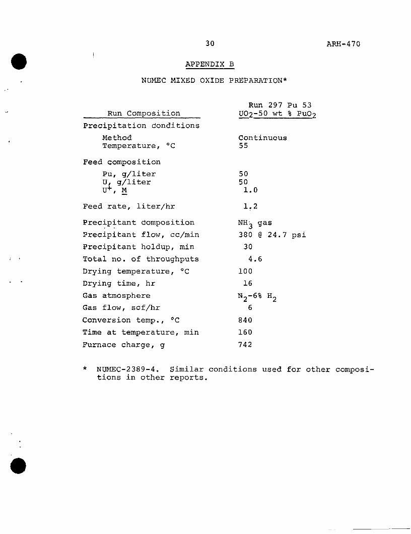
NUMEC MIXED OXIDE PREPARATION*
Run 297 Pu 53 Run Composition UO2-50 wt % PuO^
Precipitation donditions
Method Temperature, °C
Feed composition
Pu, g/liter U, g/liter U+, M
Continuous 55
50 50 1.0
Feed rate, liter/hr 1.2
Precipitant Composition
Precipitant flow, cc/min
Precipitant holdup, min
Total no. of throughputs
Drying temperature, °C
Drying time, hr
Gas atmosphere
Gas flow, scf/hr
Conversion temp., °C
Time at temperature, min
Furnace charge, g
NUMEC-2389-4. Similar conditions used for other compositions in other reports.
NH^ gas
380 @
30
4.6
100
16
N2-6%
6
840
160
742
24.7 psi
«2

31 ARH-470
APPENDIX C
/ DuPONT FLOW SHEET FOR MIXED OXIDE POWDERS I
Mixed ammonium diuranate (ADU)-Pu(OH)4 is precipitated
from nitric acid solution by ammonium hydroxide. The pre
cipitate is reduced to Pu02-U0„ by calcining.
1. Heat mixed feed solution to 8 0 °C.
2. Slowly add approximately 50 liters of 29% ammonium
hydroxide to reach pH 9. Elapsed time: 75 min.
3. Transfer slurry to continuous filter.
4. Wash cake with 50% ammonia-50% acetone.
5. Remove precipitate from filter, and dry.
6. Place powder in calcining furnace.
7. Heat powder to 700 °C for 2 hr and cool under atmos
phere of 50% hydrogen and 50% nitrogen.
8. Remove powder from furnace, and weigh.
9. Transfer calcined powder to crushing station.
10. Cycle time: 3 hr per 2 kg Pu; one operator.
Equipment
1. Precipitator.
2. Continuous filtration unit.
3. Transfer system.
4. Calcining furnace.
Processing Rate: 83,0 kg mixed oxide/day.
DP-838.^^^

32 ARH-470
APPENDIX D
, SMALL-SCALE BATCH RUN RESULTS //
' ^' FILTRATION RATES
Small-batch precipitations were initially made to test
filtration rates. Direct and reverse strikes were made,
testing the variables feed and ammonia concentrations; hot
and cold precipitations and filtrations; digestion time and
temperature; and final pH. Variations of filtration rate
were found, but not until the pH data were expanded to show
the pH over the entire precipitation did the data show a
correlation. It was noted that the Vallecitos flow sheet
did not produce a readily-filterable slurry.
The next phase of the work was more sophisticated. Small-
scale continuous precipitations were made with the intent to
maintain a narrow range of pH values through the precipitation
period. Also, resulting filter cakes were hydrogen-reduced
and powder characteristics were determined.
The data now fitted the scheme found for an uranium-only
system: since the derivation of the parameters for the (8)
uranium-only system has been shown in a previous report,
they will not be given here for the uranixim-plutonium system.
Table V shows the typical process specifications for an ADU
(ammonium diuranate) precipitation.
Table VI shows some of the run conditions used in small-
batch runs studies of mixed oxide precipitation. From these
results it was concluded that the ammonia precipitation of
uranium-plutonixim salts could be made under conditions giving
relative filtration rates comparable to plutonium oxalate;
and thus filterable on a continuous drum filter. A con
tinuous precipitation at a pH 5.0 + 0.5 should be used. The
feed should be about 100 g/liter total actinides, and a di
lute (3 M) ammonium hydroxide strike solution should be used

33 ARH-470
TABLE V TYPICAL PROCESS SPECIFICATIONS
FOR ADU PRECIPITATION*
Variable Basis
Feed Solution Nitrate or chloride system <1.25 M uranium > 0.1 M uranium 0.5 N to 3.0 N acid Purity better than product
Tested, laboratory work. Limit tested. Excessive solution volumes, Limits tested. Little purification demonstrated.
Strike Solution CP grade Low carbonate Low impurities
M NH4OH = N (feed acid) + 2.3 M (feed U)
Used in laboratory work. To keep waste losses down. To keep product purity up. Keeps feed and strike volumes about equal for ease of control.
Strike Conditions
Continuous 55 + 5 °C Vigorous agitation 10-20 min digestion Maximum pH 6.0 Minimxim pH 4.0
Wash Solution
Flow, to give dry cake Composition - to be pH >7.0 for composited feed and wash
Demonstrated. Based on results of prior work. Used in development work. Used in development work. Filterable below this value. Losses high below this value.
Required for handling. Ensure low waste loss.
* From RL-SEP-924.

•
TABLE VI
SMALL BATCH RUNS URANIUM-PLUTONIUM AMMONIA COPRECIPITATION
FILTRATION RATE STUDIES
Strike Rate Temperature, °C gH Run
P-1 3-13
50-4 5-4 3-11
50-3 3-10 3-14 4-18 P-2
2-C 3-5 5-3 3-1 3-6
2-J
Form
Continuous Continuous Continuous Continuous Continuous
Continuous Continuous Continuous Continuous Continuous
Direct Direct Continuous Direct Direct
Direct (Vallecitos)
Control
pH pH pH pH pH
pH pH Flow pll pH
_ -pH -—
g/min
1 1 1 1 1
1 1 1 5
-1
0. 2. 1 5 2.
1
6 5
5
Strike
50 50 50 50 50
50 50 50 50 50
25 50 50 50 50
25
Filtration
50 25 50 50 25
50 25 25 25 50
25 25 50 25 25
25
Final
5.3 5.3 6.3 5.9 4.6
7.7 5.6 7.0 8.0 6.3
_
8.0 4.4 9.4 8.5
9.5
Range
4.5-6,5 4.5-6.5 4.6-6.0 4.5-6.0
4.2-7.7 4.0-6.8 6.5-7.5 5.9-7.0 4.5-5.0
_
0.0-8.1 4.5-5.0 0.0-9.4 0.0-8.5
0.0-9.5

35 ARH-470
to facilitate pH control. Agitation and digestion time com
parable to plutonium oxalate technology should be used. The
precipitation, digestion, and filtration should be 55 + 5 °C.
A dilute ammonium hydroxide wash will keep actinide losses
down if the filtrate is raised to pH 7.0 or above.
II. OXIDE PROPERTIES
Since considerable effort was devoted to achieving favor
able slurry filtration rates, there were a large number of
small batches of filtered precipitates available for evalua
tion. Selected batches were air-dried, hydrogen-reduced; and
powder samples submitted for analysis. As powder analysis
techniques were being developed throughout the program, only
x-ray diffraction analyses were taken on early samples—
Table VII shows these results. About two-thirds of these x-ray
diffraction results had the specification value of <1% "free"'
PUO2.
Later runs, especially those with favorable filtration
rates, were only partially examined; Table VIII shows these
runs, which had run conditions given in Table VI, page 34.
The correlation of the x-ray diffraction data was possi
ble only with pH; all other parameters being studied (con
centrations, temperatures, etc.) in relation to filtration
rates, did not give any correlation with the % "free" PuOp
determined in the x-ray powder diffraction patterns. Where
pH data are complete, it appears that the system must not
see an extended period of pH less than 5.5; direct strikes
(runs which go from 0.0 to higher pH's) do not confirm this—
possibly because the transition period is rather rapid.
The data of Table VII were also difficult to correlate.
Except for O/M ratio (which probably has very little depend
ence on precipitation conditions), the results varied greatly.
Since the prototype runs were made at the more advanced stages

36 ARH-470
TABLE VII
SMALL BATCH RUNS URANIUM-PLUTONIUM AMMONIA COPRECIPITATION
X-RAY DIFFRACTION RESULTS
Run No.
1-2 1-3 1-4 1-5 1-6
1-7 1-A 1-B 1-C 1-D
1-F 1-G 1-H l-I 1-J
1-L 1-M 1-0 1-P 2-D
2-G 2-H 2-1 2-Q 2-T
44-1* 44-2* 44-3*
% "Free" PuO^
<1 <1 <1 ^1 <1
<1 <1 <1 <1 <1
<1 <1 <1 <1 <1
<1 <1 <1 <1 4
3 <1 <1 ^1 1
<1 <1 = 1
Strike
Continuous Continuous Continuous Continuous Continuous
Reverse Continuous Continuous Continuous Continuous
Direct Continuous Continuous Reverse Direct
Reverse Continuous Reverse Reverse Continuous
Continuous Continuous Continuous Continuous Direct
Continuous Continuous Continuous
pH Range
7.1-8.2 6.5-8.0
6.5-8.5
5.2-7.0
5.4-7.0 6.0-7.1 6.3-7.5 4.0-7.0
2.8-7.0 5.5-6.0 5.4-7.3
Fina pH
8.0
7.7
7.7
9,0
8,5 8.2
9.5 9.0 -
9.3 -
«
-—
4.0
7.5 —
7.3
These runs were larger-scale runs which took longer than the others.

37 ARH-470
TABLE VIII SMALL BATCH RUNS
URANIUM-PLUTONIUM AMMONIA COPRECIPITATION POWDER ANALYTICAL RESULTS
X-Ray Surface Run No.
P-1 3-13 5-4 3-11
3-10 P-2 3-1 3-6
Diffraction % "Free" PuO^
<1 3-5 <1 1-3
<1 <1 3-5 <1
O/M Ratio
2.282 1.997 2,135 2,150
2.154 2.034 2.075 2.083
Density, Bulk
0.72 0.65 1.35 0.93
0,73 0,75 1.18 1.23
g/cc Tap
1.10 1.02 2.13 1.47
1.20 1.12 1.72 1.63
Area M2/g
18.6 3.4 3.9 4.2
12.3 17.7 4.4 4.0
2-J <1 2.010 - 1.62 4,1
of the program, the results of these small batch runs is not
given as much weight as are the powder properties from the
prototype runs.
Extensive work has been done at the Oak Ridge Y-12 plant
on UNH precipitation conditions for producing sinterable-(13)
grade UO2 powder. The application of those data to the
mixed oxide precipitation step should be weighed with care,
since Y-12 precipitated from a fluoride-bearing media, and the
feed did not have plutonium present. However, the Y-12
workers note that temperature, feed concentration, and agita
tion are important variables in respect to final oxide sur
face area.
It has further been claimed that pH affects the sin-
terability of uranium dioxide formed from continuously-
precipitated ADU—with low densities below a pH of 5,0, and
high densities above 6.5 pH.

38 ARH-470
Complete evaluation of powder properties was not done
during this work. Further investigation in this area is
needed, especially in respect to sinterability of pellets. ;' )
0