uncrewed aircraft systems (uas) traffic management (utm)
TRANSCRIPT

Uncrewed Aircraft Systems (UAS) Traffic Management (UTM)
UTM Pilot Program (UPP)
UPP Phase 2 Final Report Version 1.0
July 29, 2021
______________________________________ __________________
Steve Bradford, Date FAA Chief Scientist NextGen Development, UTM RTT Co-Lead
______________________________________ __________________
Parimal Kopardekar, Date NASA Senior Technologist for A Principal Investigator NASA Ames Research Center, UTM RTT Co-Lead
Steve Bradford (Jul 30, 2021 05:45 EDT)Steve Bradford Jul 30, 2021
Parimal Kopardekar (Aug 2, 2021 10:30 PDT)Parimal Kopardekar Aug 2, 2021
UTM Pilot Program Phase 2 Version 1.0 Final Report July 29, 2021
i
PAGE LEFT INTENTIONALLY BLANK

UTM Pilot Program Phase 2 Version 1.0 Final Report July 29, 2021
ii
Version History
Date Revision Version
July 29, 2021 Initial Release 1.0
UTM Pilot Program Phase 2 Version 1.0 Final Report July 29, 2021
iii
Table of Contents
1 Introduction ............................................................................................................................. 1
1.1 Background ..................................................................................................................... 1
1.1.1 Uncrewed Aircraft Systems (UAS) Traffic Management (UTM) .............................. 1
1.1.2 UTM Pilot Program Phase 1 (UPP1) .......................................................................... 2
1.1.3 UTM Pilot Program Phase 2 (UPP2) .......................................................................... 2
1.2 Document Scope ............................................................................................................. 4
2 UPP2 Overview ....................................................................................................................... 5
2.1 Demonstrated Capabilities .............................................................................................. 5
2.2 Key UTM Elements in UPP2 .......................................................................................... 5
2.2.1 UTM Architecture ....................................................................................................... 5
2.2.2 UAS Service Supplier (USS) ...................................................................................... 6
2.2.3 Flight Information Management System (FIMS) ....................................................... 7
2.2.4 Remote Identification (Remote ID) ............................................................................ 9
2.2.5 UAS Volume Reservation (UVR) .............................................................................. 9
2.2.6 Message Security ........................................................................................................ 9
2.3 UPP2 Partners and FAA Support.................................................................................. 10
2.3.1 Test Site Partners ...................................................................................................... 10
2.3.2 FAA NextGen Integration and Evaluation Capability (NIEC) Lab .......................... 11
2.4 Data Collection Approach ............................................................................................ 11
2.4.1 Measures of Effectiveness (MOEs) .......................................................................... 11
2.4.2 Performance Attributes (PAs) ................................................................................... 12
3 UPP2 Execution..................................................................................................................... 14
3.1 USS Onboarding and Checkout .................................................................................... 14
3.2 Shakedowns .................................................................................................................. 16
3.2.1 Shakedown 1 ............................................................................................................. 17
3.2.2 Shakedown 2 ............................................................................................................. 18
3.3 Final Demonstrations .................................................................................................... 20
4 Demonstrated Capabilities and Outcomes ............................................................................. 22
4.1 High-Density Operations .............................................................................................. 22
4.1.1 VT-MAAP Operating Densities ............................................................................... 23
4.1.2 NYUASTS Operating Densities ............................................................................... 24

UTM Pilot Program Phase 2 Version 1.0 Final Report July 29, 2021
iv
4.2 UAS Volume Reservation (UVR) ................................................................................ 25
4.2.1 VT-MAAP ................................................................................................................ 26
4.2.2 NYUASTS ................................................................................................................ 28
4.2.3 Findings and Recommendations ............................................................................... 32
4.3 Strategic Deconfliction Approaches ............................................................................. 32
4.3.1 USS-to-USS Operation Intent Data Exchanges ........................................................ 34
4.3.2 USS Deconfliction Approaches ................................................................................ 35
4.3.3 Percentage of Deconflicted Operations..................................................................... 40
4.3.4 Findings and Recommendations ............................................................................... 41
4.4 Remote Identification (Remote ID) .............................................................................. 42
4.4.1 Broadcast Remote ID ................................................................................................ 44
4.4.2 Findings and Recommendations ............................................................................... 50
4.5 Support of Message Security ........................................................................................ 51
4.6 Information Queries and Correlation ............................................................................ 52
4.6.1 Correlation Query ..................................................................................................... 53
4.6.2 Historical Query ........................................................................................................ 56
4.6.3 Network Remote ID Query ....................................................................................... 57
4.6.4 Findings and Recommendations ............................................................................... 58
4.7 Public Safety Operations .............................................................................................. 59
4.7.1 Overview ................................................................................................................... 59
4.7.2 Outcomes .................................................................................................................. 60
4.7.3 Findings and Recommendations ............................................................................... 61
4.8 Off-Nominal/Contingent Events ................................................................................... 61
4.8.1 USS Conformance Monitoring ................................................................................. 61
4.8.2 Crewed Aircraft Detection and Alert ........................................................................ 63
4.8.3 Findings and Recommendations ............................................................................... 65
5 Conclusion ............................................................................................................................. 67
5.1 Congressional Mandates ............................................................................................... 68
5.2 Summary of Findings and Recommendations for UPP2 .............................................. 69
5.2.1 High Density Operations ........................................................................................... 69
5.2.2 UAS Volume Reservation (UVR) ............................................................................ 70
5.2.3 Strategic Deconfliction Approaches ......................................................................... 70

UTM Pilot Program Phase 2 Version 1.0 Final Report July 29, 2021
v
5.2.4 Remote Identification (Remote ID) .......................................................................... 71
5.2.5 Support of Message Security .................................................................................... 72
5.2.6 Information Queries and Correlation ........................................................................ 72
5.2.7 Public Safety ............................................................................................................. 73
5.2.8 Off Nominal/Contingent Events ............................................................................... 73
5.3 UTM Pilot Program Closeout ....................................................................................... 73
5.4 Next Steps – Path to Implementation ........................................................................... 74
Appendix A UPP2 Aircraft........................................................................................................ 75
A.1 NYUASTS Aircraft Overview ...................................................................................... 75
A.2 VT-MAAP Aircraft Overview ...................................................................................... 76
A.3 UAS Platform Details ................................................................................................... 77
Appendix B UAS Test Site’s Partner USS Summaries (UPP2) ................................................ 82
B.1 AiRXOS ........................................................................................................................ 82
B.2 AirMap .......................................................................................................................... 82
B.3 ANRA ........................................................................................................................... 82
B.4 AX Enterprize ............................................................................................................... 82
B.5 OneSky .......................................................................................................................... 82
B.6 Wing .............................................................................................................................. 83
Appendix C Method for Calculating UAS Operational Density ............................................... 84
Appendix D Measuring Percentage of Deconflicted Operations .............................................. 85
Appendix E References ............................................................................................................. 86
Appendix F Acronyms .............................................................................................................. 87

UTM Pilot Program Phase 2 Version 1.0 Final Report July 29, 2021
vi
List of Figures
Figure 1-1: UPP Test Sites, Partners, and Stakeholders ................................................................. 4
Figure 2-1: UTM Notional Architecture ......................................................................................... 6
Figure 3-1: UPP2 Execution Timeline .......................................................................................... 14
Figure 3-2: Operations Utilizing USS Network Exchanges During Shakedown 1 ...................... 18
Figure 3-3: Operations Utilizing USS Network Exchanges During Shakedown 2 ...................... 19
Figure 3-4: Operations Utilizing USS Network Exchanges During Final Demonstrations ......... 21
Figure 4-1: Time Logs of Number of Aircraft and Operational Density for Use Cases 1 & 2 .... 23
Figure 4-2: VT-MAAP Operational Densities by Use Case Iteration .......................................... 24
Figure 4-3: NYUASTS Demo Operational Densities (within 0.2 square nautical miles) ............ 25
Figure 4-4: ANRA Display with UVR ......................................................................................... 26
Figure 4-5: AirMap Display with UVR ........................................................................................ 26
Figure 4-6: AiRXOS Display with UVR ...................................................................................... 27
Figure 4-7: NYUASTS UPP2 Final Demonstration Constraints .................................................. 29
Figure 4-8: AiRXOS First Responder Application ....................................................................... 30
Figure 4-9: ANRA Constraint Entry ............................................................................................. 31
Figure 4-10: AX Enterprize Constraint Entry ............................................................................... 31
Figure 4-11: FAA Display Showing Multiple Ops Spatially Deconflicting ................................. 33
Figure 4-12: Operation Intent Exchange Performance – NYUASTS ........................................... 34
Figure 4-13: Operation Intent Exchange Performance – VT-MAAP ........................................... 35
Figure 4-14: ANRA USS Indication of Conflict .......................................................................... 37
Figure 4-15: Airmap App Display During Planning..................................................................... 38
Figure 4-16: AiRXOS Warning Message of Conflict Between BVLOS Flights ......................... 38
Figure 4-17: ASTM Remote ID Standard Scope .......................................................................... 43
Figure 4-18: AX Enterprise Broadcast Remote ID Transmitter ................................................... 44
Figure 4-19: AX Remote ID Receiver App .................................................................................. 45
Figure 4-20: AX Remote ID Basic Details ................................................................................... 45
Figure 4-21: TM-RID Receiver Application ................................................................................ 46
Figure 4-22: TM-RID Verified UAS Information ........................................................................ 46
Figure 4-23: Slant Range of Broadcast Remote ID using Bluetooth v4 vs. Bluetooth v5 ........... 47
Figure 4-24: Broadcast Remote ID Detection Latency ................................................................. 48
Figure 4-25: ANRA Broadcast Remote ID App ........................................................................... 49

UTM Pilot Program Phase 2 Version 1.0 Final Report July 29, 2021
vii
Figure 4-26: Broadcast Remote ID Measured RSSI as a Function of Range ............................... 50
Figure 4-27: Basic Overview of Digital Signing and Validation in UPP2 ................................... 51
Figure 4-28: Correlation Query Data Exchanges.......................................................................... 54
Figure 4-29: Admin Portal Correlation Query .............................................................................. 55
Figure 4-30: Correlation Query from Third-Party ........................................................................ 55
Figure 4-31: Historical Query Latency – NYUASTS................................................................... 56
Figure 4-32: Historical Query Latency – MAAP ......................................................................... 57
Figure 4-33: Remote ID Display Interaction Latency .................................................................. 58
Figure 4-34: Nonconforming and Contingent UAS at NYUASTS .............................................. 63
Figure 4-35: ANRA USS Display Notification of a Crewed Aircraft .......................................... 64
Figure 4-36: ACAS sXu Pilot Guidance ....................................................................................... 65
Figure 5-1: UTM Agile Capability Development Cycle .............................................................. 68
List of Tables
Table 2-1: Test Site Partners ......................................................................................................... 10
Table 2-2: UPP2 Measures of Effectiveness ................................................................................ 12
Table 2-3: UPP2 Performance Attributes ..................................................................................... 12
Table 3-1: Summary of UPP2 Onboarding and Checkout Activities ........................................... 15
Table 3-2: Summary of UPP2 Shakedown Activities................................................................... 16
Table 3-3: Summary of UPP2 Process and Activities .................................................................. 20
Table 3-4: UPP2 Demonstrated Use Cases ................................................................................... 20
Table 4-1: Capability to PA and MOE Mapping .......................................................................... 22
Table 4-2: UVR Metrics ............................................................................................................... 25
Table 4-3: UVR Response by Affected Operation ....................................................................... 27
Table 4-4: UVR Findings and Recommendations ........................................................................ 32
Table 4-5: Strategic Deconfliction Metrics ................................................................................... 33
Table 4-6: VT-MAAP Operations Totals and Percentage Requiring Deconfliction .................... 40
Table 4-7: Strategic Deconfliction Findings and Recommendations ........................................... 41
Table 4-8: Remote ID Metrics ...................................................................................................... 43
Table 4-9: Remote ID Findings and Recommendations ............................................................... 50
Table 4-10: Information Query Metrics ........................................................................................ 53
Table 4-11: Information Query Findings and Recommendations ................................................ 58

UTM Pilot Program Phase 2 Version 1.0 Final Report July 29, 2021
viii
Table 4-12: UPP2 Public Safety Participants ............................................................................... 59
Table 4-13: Performance Attributes.............................................................................................. 60
Table 4-14: Public Safety Operations Findings and Recommendations ...................................... 61
Table 4-15: Off-Nominal/Conformance Metrics .......................................................................... 61
Table 4-16: Off-Nominal/Contingency Event Findings and Recommendations .......................... 65
Table 5-1: Congressional Requirements Summary ...................................................................... 68
Table A-2: NYUASTS Aircraft Overview ................................................................................... 75
Table A-3: VT-MAAP Aircraft Overview ................................................................................... 76
Table A-4: 3DR Aero-M ............................................................................................................... 77
Table A-5: DJI Inspire 1 ............................................................................................................... 77
Table A-6: DJI Inspire 2 ............................................................................................................... 77
Table A-7: DJI Matrice 200 .......................................................................................................... 78
Table A-8: DJI Matrice 210 .......................................................................................................... 78
Table A-9: DJI Mavic ................................................................................................................... 78
Table A-10: DJI Mavic Air 2 ........................................................................................................ 79
Table A-11: DJI Mavic Pro........................................................................................................... 79
Table A-12: DJI MG-1.................................................................................................................. 79
Table A-13: DJI Phantom 4 .......................................................................................................... 80
Table A-14: DJI S900 ................................................................................................................... 80
Table A-15: DJI S1000 ................................................................................................................. 80
Table A-16: Microdrones MD4 .................................................................................................... 81
Table A-17: SAGA E450 .............................................................................................................. 81
Table A-18: Wing Hummingbird 7000......................................................................................... 81
Table F-1: Acronyms .................................................................................................................... 87

UTM Pilot Program Phase 2 Version 1.0 Final Report July 29, 2021
1
1 Introduction
The Uncrewed Aircraft Systems (UAS) Traffic Management (UTM) Pilot Program (UPP) is an important activity for developing, expanding, and field testing the next set of industry and Federal Aviation Administration (FAA) capabilities required to support UTM. In summer 2019, the FAA, National Aeronautics and Space Administration (NASA), and industry partners successfully completed UPP Phase 1 (UPP1) demonstrations. In fall 2020, UPP Phase 2 (UPP2) demonstration activities were successfully completed. This final report concludes UPP2.
1.1 Background
1.1.1 Uncrewed Aircraft Systems (UAS) Traffic Management (UTM)
Operators of UAS are continuously exercising new, beneficial applications for their operations, including activities such as goods delivery, infrastructure inspection, search and rescue, and agricultural monitoring. Currently, limited infrastructure is in place to support management of the continuing expansion of UAS operations within the National Airspace System (NAS). Incorporation of UAS operations of increasing density and complexity, particularly those flown Beyond Visual Line of Sight (BVLOS), presents a variety of novel challenges. Implementation of a safe and efficient UTM service environment, including supporting infrastructure, is necessary to enable the incorporation of routine BVLOS operations in low-altitude airspace (below 400 feet Above Ground Level [AGL]).
The FAA and NASA have joint interests in identifying innovative and transformative solutions for UTM that can effectively respond to integration challenges without compromising the safety or efficiency of the NAS. In 2015, a UTM Research Transition Team (RTT) was formed between the FAA and NASA to jointly develop and enable a UTM framework to manage routine Visual Line of Sight (VLOS) and BVLOS UAS operations in airspace where air traffic services are not provided.
UTM is the manner in which the FAA will support UAS operations conducted in low-altitude airspace. UTM utilizes industry’s ability to supply services under FAA’s regulatory authority where these services do not currently exist. It is a community-based, cooperative traffic management system in which the operators and entities providing operation support services (i.e., UAS Service Suppliers [USSs]) are responsible for the coordination, execution, and management of operations, with rules established by the FAA.
To support UTM implementation, collaborative research and test activities have been established to support government, industry, and operator development of services and technologies that address the safety, efficiency, and interoperability needs applicable to a cooperatively managed traffic environment. This started with the UTM RTT Technical Capability Level (TCL) demonstration activities, which concluded in 2020. As technologies and capabilities were transferred to the FAA, UPP was established to support deployment of UTM capabilities within FAA systems and to provide a collaborative environment for FAA, NASA, industry, operators, and other stakeholders to test maturing services and systems in preparation for UTM implementation.

UTM Pilot Program Phase 2 Version 1.0 Final Report July 29, 2021
2
UTM development and implementation establishes requisite services, roles and responsibilities, information architecture, data exchange protocols, software functions, infrastructure, and performance requirements for enabling the management of low-altitude UAS operations.
1.1.2 UTM Pilot Program Phase 1 (UPP1)
The FAA Extension, Safety, and Security Act of 2016, Section 2208(b)(1) [1] specifies that:
(1) The [FAA] Administrator, in coordination with the Administrator of the National Aeronautics and Space Administration, the Drone Advisory Committee, the [FAA] research advisory committee…and representatives of the unmanned aircraft industry, shall establish a UTM system pilot program.
UPP1 was established as an important component for identifying the next set of FAA and industry capabilities required to support UTM operations. These capabilities support the sharing of information that promotes situational awareness and deconfliction (i.e., cooperative separation). Some of the UTM capabilities successfully demonstrated in UPP1 included: (1) sharing of operation intent between operators, (2) the ability for a USS to generate a UAS Volume Reservation (UVR), and (3) providing access to FAA Enterprise Services to support shared information (accomplished via the Flight Information Management System [FIMS]).
On January 14, 2019, The Honorable Elaine L. Chao, Secretary of the United States Department of Transportation, announced the FAA’s selection of three industry teams to partner with the agency in UPP:
• The Virginia Tech, Mid-Atlantic Aviation Partnership (VT-MAAP)
• The Northern Plains UAS Test Site (NPUASTS)
• The Nevada Institute for Autonomous Systems (NIAS)
In summer 2019, the FAA, NASA, and their industry partners successfully completed UPP demonstrations. This consisted of a series of preparation flights and final flight demonstrations, with both live UAS flights and simulated UTM operations at each test site. The flight activities were executed while participating UAS operators (flying live and/or simulated Uncrewed Aircraft [UA] 1) exchanged information with one another and with FIMS via communication with participating USSs, each of which were connected to a UPP demonstration platform. Through the planning and execution of UPP activities, each of the three UPP partnerships successfully demonstrated all the requisite capabilities. While the specifics of each use case varied between the partnerships, the key UTM capabilities were exercised with success at each site.
1.1.3 UTM Pilot Program Phase 2 (UPP2)
Recognizing the importance in defining and expanding capabilities needed to support UTM, the FAA Reauthorization Act of 2018, Section 375(b) [2] details additional requirements for UPP:
1 The term Uncrewed Aircraft (UA) is used to distinguish the vehicle itself from the overall system (UAS), which is inclusive of the vehicle, the ground control station, and a system of communications with the vehicle.

UTM Pilot Program Phase 2 Version 1.0 Final Report July 29, 2021
3
(b) Completion of UTM System Pilot Program.—The Administrator shall ensure that the UTM system pilot program…is conducted to meet the following objectives of a comprehensive UTM system by the conclusion of the pilot program:
(1) In cooperation with [NASA] and manned and unmanned aircraft industry stakeholders, allow testing of unmanned aircraft operations, of increasing volumes and density, in airspace above test ranges [FAA Test Sites],…as well as other sites determined by the Administrator to be suitable for UTM testing, including those locations selected under the pilot program required in the October 25, 2017, Presidential Memorandum entitled, “Unmanned Aircraft Systems Integration Pilot Program”... (2) Permit the testing of various remote identification and tracking technologies evaluated by the [UAS] Identification and Tracking Aviation Rulemaking Committee. (3) Where the particular operational environment permits, permit blanket waiver authority to allow any unmanned aircraft approved by a UTM system pilot program selectee to be operated under conditions currently requiring a case-by-case waiver under part 107, title 14, Code of Federal Regulations, provided that any blanket waiver addresses risks to airborne objects as well as persons and property on the ground.
To meet the requirements as specified by Congress prior to the conclusion of UPP, UPP2 was initiated in 2019. In April 2020, the FAA selected two FAA UAS test sites (shown in Figure 1-1) to partner with the agency for UPP2 development, testing, and demonstration activities:
• Virginia Tech, Mid Atlantic Aviation Partnership (MAAP)
• New York UAS Test Site (NYUASTS)2
In cooperation with NASA, the selected FAA UAS test sites, industry stakeholders, public safety stakeholders, and UAS Integration Pilot Program (IPP) participants, the FAA conducted simulation and live testing that included:
• Increasing volumes and density of UAS operations in live-flight environments.
• Remote Identification (ID) technologies recommended by the UAS ID Advisory and Rulemaking Committee (ARC) and specified in the ASTM Standard Specification for Remote ID and Tracking (hereafter referred to as the “ASTM Specification for Remote ID”) [3].
• Testing to Draft Version 0.3.5 of ASTM WK63418: New Specification for UTM USS Interoperability (hereafter referred to as the “ASTM Draft Specification for UTM”) [4, including strategic deconfliction, conformance monitoring.
• Field testing of end-to-end technologies between UTM actors (e.g., USS-to-USS, USS-to-FIMS), including message security.
2 The Northeast UAS Airspace Integration Research (NUAIR) manages the operations of the NYUASTS at Griffiss International Airport in Rome, NY, one of just seven FAA-designated UAS test sites in the United States, and is responsible to the FAA and NASA to conduct operations for UAS and Advanced Air Mobility (AAM) Electric Vertical Take-Off and Landing (eVTOL) testing. AX Enterprize acted as the technical lead and test director on the project.

UTM Pilot Program Phase 2 Version 1.0 Final Report July 29, 2021
4
• Participation of public safety stakeholders as both UAS operators (e.g., operation within UVRs) and on-ground stakeholders (e.g., request UVRs, information requests to FAA).
Figure 1-1: UPP Test Sites, Partners, and Stakeholders
1.2 Document Scope
This document provides a report of UPP2 demonstration results. It includes an overview of UPP2, which details demonstrated capabilities, describes key UTM elements that were a focus of UPP2 activities, details on test sites/supporting participants and reviews the data collection approach. The report then provides a summary of the execution of UPP2 activities, starting with USS onboarding and checkouts, progressing to shakedown tests, and concluding with final demonstration activities. Next, the report provides details across the various demonstrated capabilities, which includes relevant data and analysis, survey responses from participants, and findings/recommendations. The report then provides a conclusion for UPP and discusses next steps as they relate to UTM implementation.

UTM Pilot Program Phase 2 Version 1.0 Final Report July 29, 2021
5
2 UPP2 Overview
This section provides a high-level overview of the UPP2 project, including a review of the capabilities that were demonstrated, background information on key UTM elements applicable to UPP2, an overview of test site partners and supporting actors, and a review of project activities.
2.1 Demonstrated Capabilities
UPP2 demonstrates the following emerging UTM capabilities that will support BVLOS operations.
• The FAA FIMS prototype and infrastructure, which gives the FAA access to information from industry and other stakeholders.
• New technologies and data to validate the latest standards for Remote ID and support authorized users with specific operator data.
• In-flight separation from other UA or crewed aircraft in high-density airspace to validate recently proposed international UTM standards to help UA avoid each other.
• UVRs to notify UAS operators of emergencies and make sure other UTM capabilities work properly in these scenarios.
• Secure information exchanges between the FAA, industry, and authorized users to ensure data integrity.
2.2 Key UTM Elements in UPP2
This section provides background information on key UTM elements that are a focus of UPP2 and are discussed throughout this report. In general, detailed concepts can be found in the FAA UTM Concept of Operations (ConOps) Version 2.0 [5].
2.2.1 UTM Architecture
Within the UTM ecosystem, the FAA maintains its regulatory and operational authority for airspace and traffic operations; however, the operations are not managed by Air Traffic Control (ATC). Rather, they are organized, coordinated, and managed by a federated set of actors in a distributed network of highly automated systems via Application Programming Interfaces (APIs). Figure 2-1 depicts a notional UTM architecture that visually identifies, at a high level, the various actors and components, their contextual relationships, and high-level functions and information flows. The gray dashed line represents the demarcation between the FAA and industry for infrastructure, services, and entities that interact as part of UTM. As shown, UTM comprises a sophisticated relationship between the FAA, operator, and various entities providing services and/or demonstrating a demand for services within the UTM ecosystem. The illustration highlights a model, which heavily leverages utilization of third-party service providers (e.g., USSs, Supplementary Data Service Providers [SDSPs]) to support the FAA and the operator in their respective roles and responsibilities.

UTM Pilot Program Phase 2 Version 1.0 Final Report July 29, 2021
6
Figure 2-1: UTM Notional Architecture
2.2.2 UAS Service Supplier (USS)
A USS is an entity that assists UAS operators with meeting UTM operational requirements that enable safe and efficient use of airspace. A USS provides three main functions:
• Acts as a communications bridge between federated UTM actors to support operators’ abilities to meet the regulatory and operational requirements for UAS operations.
• Provides the operator with information about planned operations in and around a volume of airspace so that operators can ascertain the ability to safely and efficiently conduct the mission.
• Archives operations data in historical databases as appropriate for analytics, regulatory, and operator accountability purposes.
In general, these key functions allow for a network of USSs to provide cooperative management of low-altitude operations without direct FAA involvement. The following terms are defined within the context of USSs.

UTM Pilot Program Phase 2 Version 1.0 Final Report July 29, 2021
7
• USS Network: The amalgamation of USSs connected to each other, exchanging information on behalf of subscribed operators. USSs share operation intent data, airspace constraint information, and other relevant details across the network to ensure shared situational awareness for UTM participants. In the UTM construct, multiple USSs can operate in the same geographical area.
o Note: As noted in a recent FAA Medium article [6] “UTM services will be foundational for the industry’s ability to scale and make many drone operations economically viable.” The USS Network as described above refers to the broader set of USS-to-USS interactions3 that support information exchanges necessary for a variety of UTM services (e.g., operator messaging, constraint management, strategic deconfliction, conformance monitoring).
• Discovery and Synchronization Service (DSS): DSS is utilized by USSs to facilitate automated data exchanges between one another within the USS network. This capability allows USSs to identify one another and exchange relevant information when USSs are in the same geographical service area.
For UPP2, participating USS APIs adhered to the ASTM Draft Specification for UTM [4], currently in development within ASTM Committee F38.02 [7].
2.2.3 Flight Information Management System (FIMS)
The FAA FIMS prototype was implemented by the FAA Next Generation Air Transportation System (NextGen) Integration and Evaluation Capability (NIEC) Lab at William J. Hughes Technical Center for UPP1. It remains in place there and has been updated since UPP1 to reflect the changes needed for the integration and testing of UPP2 activities.
In UPP2, the FAA used FIMS as an access point for information on active UTM operations. FIMS is an interface for data exchange between FAA systems and UTM participants. FIMS enables the exchange of relevant operations data between the FAA and the USS network. FIMS also provides a means for approved FAA stakeholders to query and receive limited post-hoc/archived data on UTM operations for the purposes of compliance audits and/or incident or accident investigation. FIMS is managed by the FAA and is a part of the UTM ecosystem.
The FIMS prototype consists of several key components, including FIMS Ops, FIMS Authorization Server (AuthZ), and the FIMS Admin Portal.
3 The FAA Final Rule for Remote ID [14] elected broadcast ID over network ID. Both Remote ID technologies were tested in accordance with the ASTM Specification for Remote ID during UPP2, but USS Network exchanges also included those required to test other capabilities as detailed in the ASTM Draft Specification for UTM [4].

UTM Pilot Program Phase 2 Version 1.0 Final Report July 29, 2021
8
2.2.3.1 FIMS Ops
FIMS Ops is a central component of the FIMS. FIMS Ops collects messages and requests from small UAS (sUAS) flight activities as required by FAA policies and supplies timely decisions regarding requests as appropriate. FIMS Ops also implements the FIMS API used as the bridge of data exchanges between USSs and the FAA. FIMS Ops exists as a web-based service. It offers well-defined endpoints for exchanging data using human and machine-readable data schemas. FIMS Ops exists in context with other web-based components and services connected by known APIs via the Internet.
2.2.3.2 FIMS Authorization Server (AuthZ)
OAuth 2.0 is an authorization framework for delegated access to APIs. It involves clients that request scopes that resource owners authorize/give consent to. It is also the authorization framework used by UTM to protect APIs from unauthorized access. AuthZ is the OAuth 2.0 component that authenticates systems, and issues access tokens used to access APIs.
FIMS AuthZ provides authorization services for FIMS and USS stakeholders within UTM. FIMS AuthZ is an OAuth 2.0 compliant authorization server. The endpoints and data exchanges provided by this server are based on open standards. OAuth 2.0 requires at set of endpoints to be a compliant authorization server, but currently FIMS AuthZ has only fully implemented a subset.
2.2.3.3 Integrated Drone Identification Automated System (IDIAS)
The FAA has developed a data correlation capability to support authorized queries for information to the FAA. The FIMS component that implements the capability is known as the Integrated Drone Identification Automated System (IDIAS). The following assumptions guided the development for IDIAS.
• The FAA authorizes public safety and security entities to use data request/correlation services.
• The FAA provides access for authorized user to submit requests.
• These services support queries of internal FAA data stores.
2.2.3.4 FIMS Admin Portal
The FIMS Admin Portal is a web-based user interface accessible to internal FAA users that provides access through FIMS to data that is not provided to the public. It is used for administration of FIMS, and to provide FIMS administrators access to services for querying and analyzing UTM-related data. The Admin Portal provides an administrator with the ability to initiate queries, such as Remote ID correlation or historical. It also gives admins the ability to manage USS roles and scopes used by FIMS AuthZ for access token generation.
For the purposes of UPP2 demonstrations, the Admin Portal also provides visualizations for UTM operation intent and constraints to provide awareness of UTM activities occurring during the demonstrations.

UTM Pilot Program Phase 2 Version 1.0 Final Report July 29, 2021
9
2.2.4 Remote Identification (Remote ID)
Remote ID provides a means to address public concerns and protect for public safety vulnerabilities associated with low-altitude UAS operations, including privacy and security threats. Remote ID allows electronic identification of a UA/operator through use of a unique identifier (similar in concept to an automobile license plate). Remote ID enables accountability and traceability, particularly for BVLOS operations, where an operator and vehicle are not collocated.
For UPP2 activities, participants are conducting testing and evaluation of Remote ID technologies developed in accordance with the ASTM Specification for Remote ID [3]. This specification covers the performance requirements for Remote ID of UAS. Remote ID allows governmental and civil identification of UAS for safety, security, and compliance purposes. Remote ID is an enabler of enhanced operations such as BVLOS operations, as well as operations over people.
2.2.5 UAS Volume Reservation (UVR)
UVRs are designed to support operational safety during public safety activities (e.g., medical evacuation flights, firefighting) by notifying UTM operators of blocks of airspace in which these activities occur. UVRs may be established when activities on the ground or in the air present a potential risk to UTM safety interests. UVRs are generally short in duration (i.e., hours as opposed to days or weeks), have specified airspace boundaries, and have established start and end times. USSs participating in UPP2 provided UVR services to designated public safety participants. During UPP2 activities, a UVR that was generated by a USS upon request by a participating stakeholder was routed to other USSs to notify affected operators, as well as to the FAA via FIMS.
2.2.6 Message Security
UPP2 message security mechanisms built upon the security from UPP1 and added new capabilities to enhance data protection in UTM. Both UPP1 and UPP2 required the following.
• OAuth 2.0 access tokens to ensure proper authorization, with each UTM participant required to request access tokens from a centralized FIMS authorization server (i.e., FIMS AuthZ) [8].
• Transport Layer Security (TLS) protocols for all communications, which provided point-to-point authentication, data integrity, and encryption.
In UPP2, the FAA applied digital signatures to extend security to the message-level by ensuring data integrity, authentication, and non-repudiation. The addition of message signing implemented with trusted digital certificates enhanced the system-to-system authentication and data integrity beyond basic client credentials used in UPP1 and provided end-to-end non-repudiation for sent messages. Non-repudiation, a capability the FAA may require for post-incident analysis and auditing, ensures that the recipient of a message can confirm the identity of the message sender.
In addition to applying authorization (i.e., OAuth 2.0) and data integrity (i.e., digital signatures) approaches to the information exchanged in UPP2, the FAA looked to demonstrate the use of a

UTM Pilot Program Phase 2 Version 1.0 Final Report July 29, 2021
10
trusted Certificate Authority (CA) within a Public Key Infrastructure (PKI) for certificate issuance. The use of a known CA linked the cryptographic signature keys to a specific UPP2 entity. The PKI also allowed each entity receiving a signed message to link the signing certificate to a trusted source, or “root certificate,” to establish trust in each signing certificate. In UPP2, each UTM participant obtained trusted digital certificates from the FAA’s prototype International Aviation Trust Framework (IATF) CA. The IATF is part of an ongoing international effort by the International Civil Aviation Organization (ICAO) to establish an interoperable trust framework and ensure secure information exchange within the wider aviation industry. Outside of prototype demonstrations of IATF concepts between the FAA and EUROCONTROL, UPP2 represents one of the earliest demonstrations of IATF concepts. In applying the IATF in UPP2, the identities and certificate requests of each partner were vetted during onboarding, through a semi-automated process, by FAA personnel who coordinated with a Registration Authority and CA for certificate creation and dissemination. When approved, each system received their public key certificates from the CA, who hosted the public key certificates in an accessible location for all UTM participants.
2.3 UPP2 Partners and FAA Support
As noted in Section 2.2, UTM operations are primarily managed by a federated set of actors, including UAS operators and the USSs that support them. Given this, it is critical that UTM demonstration activities included a diverse set of stakeholders to ensure the envisioned capabilities address the varied sets of needs and interests. UPP2 focused on this need and brought together various FAA stakeholders, NASA, industry service providers, UAS operators, and public safety stakeholders to support use cases within the integrated test environment.
2.3.1 Test Site Partners
Table 2-1 provides overviews of the industry partners and other participating stakeholders who worked with VT-MAAP and NYUASTS in UPP2. The test sites oversaw project management for activities executed at their sites; provided infrastructure/services to support USS and UAS operator activities; coordinated with the NIEC lab to provide the integrated test environment; and provided additional support to the FAA, partners, and other stakeholders as needed.
Table 2-1: Test Site Partners
USS Partners Other Partners
VT-MAAP
• ANRA Technologies
• Airmap • AiRXOS • Wing
• Public Safety: Christiansburg, Blacksburg Police Department, Virginia Tech Police Department, Montgomery County Sheriff’s Department, Virginia Tech Department of Emergency Management, Radford Army Ammunition Plant

UTM Pilot Program Phase 2 Version 1.0 Final Report July 29, 2021
11
USS Partners Other Partners
NYUASTS
• ANRA Technologies
• AX Enterprize • AiRXOS • OneSky
• Public Safety: Syracuse Fire Department, Oneida County Sheriff’s Department, Albany County Sheriff’s Department
• Additional Partners: Aerodyne Measure, Johns Hopkins University – Applied Physics Laboratory, TruWeather Solutions, Skyward (a Verizon Company), Flytrex
USSs provided technologies and services to support live and simulated flights of UAS, which may include operating their own simulated and/or live UAS during flight activities. They integrated into the test environment, and ensured supporting technologies and services conformed to applicable standards and project requirements.
Public safety partners participated in several ways. This included operating UAS, using UVR services in simulated public safety conditions, testing Remote ID technologies that conform to the ASTM Specification for Remote ID [3], and use of information services4 provided to participating public safety/security personnel. One use case demonstrated such as submitting a query to correlate identification information (e.g., Remote ID Message) with FAA-held information.
Other partners supported in various ways. This includes, but is not limited to, supplementary data services, communications infrastructure, and operating UAS.
2.3.2 FAA NextGen Integration and Evaluation Capability (NIEC) Lab
The FAA NIEC lab provided infrastructure, technologies, and applicable support to enable an integrated test environment for the test sites and their partners. Activities included, but were not limited to, software development, alignment to ASTM standards, development of FAA’s UPP message security requirements5, provision of FIMS components described in Section 2.2.3, connecting USSs into FIMS infrastructure, conducting USS checkout processes to ensure applicable functional requirements were met, and facilitating data collection and reporting.
2.4 Data Collection Approach
2.4.1 Measures of Effectiveness (MOEs)
For UPP2, Measures of Effectiveness (MOEs) were developed as a means to determine if the services, systems, and technologies demonstrated during the associated activities were able to satisfactorily support operations conducted in the test environments. The capabilities identified in Section 2.1 of this document were used to develop the MOEs listed in Table 2-2.
4 UPP2 use cases 4 and 5 (see Table 3-4 for demonstrated UTM information services supporting public safety entities with RID, correlation, and historical information queries). 5 UPP2 message security requirements are an FAA-driven research area. Requirements and best practices identified during UPP activities will be provided to stakeholders to facilitate continued standards development.

UTM Pilot Program Phase 2 Version 1.0 Final Report July 29, 2021
12
Table 2-2: UPP2 Measures of Effectiveness
Label Description
UTM-MOE-1 UTM effectively supports sUAS operations staying safely separated through strategic deconfliction.
UTM-MOE-2 UTM allows for the identification of operations and operators participating in UTM through Remote ID capabilities.
UTM-MOE-3 UTM allows for priority access to the airspace for public safety missions.
UTM-MOE-4 UTM allows for common situational awareness of the airspace and operations within it through information sharing.
UTM-MOE-5 UTM allows the FAA to have on-demand access to operational data.
UTM-MOE-6 UTM participants effectively comply with message security requirements.
2.4.2 Performance Attributes (PAs)
For UPP2, Performance Attributes (PAs) were defined as a means of identifying the types of data to be collected to support post-flight analysis and determine if the services, systems, and technologies demonstrated meet the measures of effectiveness (as identified in Table 2-2). Table 2-3 details the PAs specified for UPP2.
Table 2-3: UPP2 Performance Attributes
PA ID PA Title Description MOE Supported
UTM-PA-01 Strategic deconfliction
Feedback and opinions of the current strategic deconfliction capabilities provided by the ASTM Draft Specification for UTM [4] will be captured using qualitative survey questions.
UTM-MOE-1
UTM-PA-02 Operation conformance
Are operations staying within its conformance parameters during UPP2 activities?
UTM-MOE-1
UTM-PA-04 Appropriate response by USS to unauthorized data exchanges
Are USSs responding appropriately to request with bad access tokens, e.g.: • Expired tokens • Invalid scopes • Improperly formatted • Incorrect access token subject • Invalid token signature
UTM-MOE-6

UTM Pilot Program Phase 2 Version 1.0 Final Report July 29, 2021
13
PA ID PA Title Description MOE Supported
UTM-PA-05 Appropriate response by USS to data exchanges with improper signatures
Using Test USS, submit intermittent requests to other USSs using missing or invalid signatures. Signatures may be invalid due to: • Invalid certificate (revoked, expired,
name, incorrect root) • Improper formatting • Improper USS name • Signature does not match content
UTM-MOE-6
UTM-PA-07 Remote ID data exchange performance
What is the performance of Remote ID data exchanges (broadcast, lookups, etc.), broken down by various categories? E.g., Categories: • UA broadcast to Remote ID app (if
possible) • Display provider to service provider • UAS to service provider
UTM-MOE-2
UTM-PA-08 Historical data query performance
What is the performance of Historical Data Query exchanges, broken down by various categories? E.g., Categories: • FIMS-USS queries • Public safety queries
o Initiated by third party o FAA-initiated
UTM-MOE-5
UTM-PA-09 USS network data exchange performance
What is the performance of USS network data exchanges, broken down by various categories? E.g., Categories: • USS to discovery (DSS) • Operation intent • Constraints (e.g., UVRs)
UTM-MOE-4
UTM-PA-10 Survey assessments Feedback on various aspects UTM operations and project execution.
UTM-MOE-4
UTM-PA-11 Density of operations
What is the density level of operations per defined 0.2 square nautical mile area?
UTM-MOE-4
UTM-PA-12 Priority operations Feedback and opinions of the current priority operation capabilities provided by the ASTM Draft Specification for UTM [4] will be captured using qualitative survey questions.
UTM-MOE-3

UTM Pilot Program Phase 2 Version 1.0 Final Report July 29, 2021
14
3 UPP2 Execution
UPP2 activities included USS onboarding/development and checkout, shakedown tests, and the final demonstration flights, which concluded with showcase events for each test site. Figure 3-1 shows the general timeline of these activities.
Figure 3-1: UPP2 Execution Timeline
Note on the COVID-19 Public Health Crisis: The pandemic caused by COVID-19 created initial concerns in scheduling, collaboration, and execution of activities. However, the FAA, in collaboration with NASA, UAS test sites, the test site partners, and other stakeholders/contributors, has been able to adjust approaches to coordination and development cycles to continue work towards demonstration of the targeted capabilities. Approaches included the use of teleconference tools (e.g., Zoom, GoToMeeting) when previously planned trips were no longer possible, the use of online collaboration software (e.g., Redmine, Slack, Microsoft Teams), and performing simulated flights for some missions that could not be supported with live UAS.
3.1 USS Onboarding and Checkout
Throughout spring and summer of 2020, VT-MAAP and NYUASTS worked with their partners and the FAA to prepare for flight demonstrations. This included software development, systems integration, and definition of use case test cards. As part of the preparation for flight demonstrations, the USSs and the NIEC lab conducted numerous onboarding and checkout activities.
During the onboarding and checkout process, participating USSs were required to complete connectivity tests with the NIEC UTM development environment to verify basic software/data exchange functionality (e.g., with FIMS, with other USSs) so that integrated tests could be performed during the shakedown activities. Functional tests included the ability to get access tokens from FIMS and meet UPP2 data exchange requirements, which are based on the ASTM Draft Specification for UTM [4], ASTM Specification for Remote ID [3], and FAA FIMS API. This ensured that the individual USSs were able to connect and communicate with the other UTM components prior to beginning the operational tests (i.e., shakedowns) of the capabilities outlined in Section 2.1. Table 3-1 provides a summary of the activities conducted during onboarding and checkout activities.

UTM Pilot Program Phase 2 Version 1.0 Final Report July 29, 2021
15
Table 3-1: Summary of UPP2 Onboarding and Checkout Activities
UPP2 Event(s) VT-MAAP NYUASTS
USS Onboarding • USS submits an onboarding form to the FAA • USS obtains a digital certificate from the FAA’s IATF prototype CA • USS resolves certificate formatting discrepancies and key exchanges • USS resolves new message security implementations per FAA
requirements and as applicable from the ASTM Specification for Remote ID [3] and ASTM Draft Specification for UTM [4]
• USS undergoes automated and manual testing with FAA ensuring applicable requirements have been met
Apr. 15 – Apr. 30 (2020)
Apr. 15 – Apr. 30 (2020)
Checkouts • Check that USSs meet applicable functional requirements, e.g.,
ability to sign and validate messages using IATF certificates • Check that interactions of USS-FIMS, USS-USS, and USS-UAS are
functional; confirm USS ability to connect and communicate with the other UTM components prior to beginning operational tests
• Check for and address any technical issues related to message signing and validation (e.g., formatting and encoding differences)
• Check to validate the system interactions foundational to UTM • Check that sharing of operation and UVRs with FAA is successful • Check that test operation query from FIMS is successful
Aug. 3 – Sept. 10 (2020)
Aug. 12 – Sept. 10 (2020)
UPP2 USS onboarding, development, and checkout processes were performed in three stages during spring and summer of 2020.
• Stage 1 – Message Signing Certificates and Token Access: Each USS completed an onboarding form with the organizational information necessary to request a signing certificate on their behalf. USSs verified the validity of the certificate by requesting a token from the FIMS authorization server. During checkouts, most issues were related to the message that was signed not being identical to the message that was sent; details on how various issues were addressed and message security lessons learned are provided in Section 4.5.
• Stage 2 – Automated Tests: The NIEC supported a suite of automated tests that sent data to participating USSs to verify functionality and test for proper handling of invalid data. The tests were run at the request of a USS when they were ready. Issues discovered and resolved at this stage were related to USSs receiving and verifying signatures, as this was the first opportunity to test this functionality.

UTM Pilot Program Phase 2 Version 1.0 Final Report July 29, 2021
16
• Stage 3 – Manual Tests: Manual checkout tests were also conducted between the NIEC and USSs that tested a series of USS and FIMS capabilities. These tests included:
o Operation intent sharing via posts to DSS and necessary subscribers o Operation state changes (e.g., activated, ended) o UVR constraint message posts to DSS and necessary subscribers o NIEC Remote ID queries o NIEC historical data queries
Testing consisted of one-hour sessions with each USS as they completed stage 2. Some common issues discovered and resolved at this stage were incorrect handling of the deletion of operations and constraints, configuration issues related to subscriptions, and the data that should be returned from a historical query.
3.2 Shakedowns
The operational testing of UPP2 capabilities in the integrated test environment was conducted through a number of shakedown activities. These activities tested end-to-end systems through the operational use cases. During these pre-demonstration activities, UPP2 partners were able to exercise their vehicles and systems to test to the various standards, concepts, and operational requirements. In many cases, this initial test was the first validation of standards that were tested across different commercial partners in a live environment, revealing a number of challenges previously unknown to the UTM community (see relevant findings and recommendations in Section 4). The activities conducted prior to the final demonstration allowed UPP2 partners to identify and resolve a number of challenges with these advanced UTM capabilities that ensured the success of the final demonstration. Table 3-2 provides a summary of the activities conducted during shakedown activities.
Table 3-2: Summary of UPP2 Shakedown Activities
UPP2 Event(s) VT-MAAP NYUASTS
Shakedown 1 • Test functionalities/technologies intended to support demo activities o Sharing of operation intent pre-flight o Changes to operation intent while in flight o Strategic deconfliction between operations o Off-nominal situation reporting o USS data/message exchanges (e.g., intent, notifications) o DSS use per ASTM Draft Specification for UTM [4] o UVR request and processing
Sept. 14 – Sept. 18 (2020)
Aug. 31 – Sept. 4 (2020)

UTM Pilot Program Phase 2 Version 1.0 Final Report July 29, 2021
17
UPP2 Event(s) VT-MAAP NYUASTS
o Remote ID technologies, including broadcast and network exchanges
Shakedown 2 • Testing capabilities and connections in real-time • Tested correlation queries • First run-through of use cases with live flights and simulations
Oct. 12 – Oct. 16 (2020)
Oct. 5 – Oct. 9 (2020)
3.2.1 Shakedown 1
NYUASTS – Shakedown 1 for NYUASTS was conducted at the Griffiss International Airport and a park in the City of Rome, New York from August 31-September 4, 2020. Due to COVID-19-related travel restrictions, some partners were unable to attend in person and instead participated remotely. The Northeast UAS Airspace Integration Research (NUAIR) (who manages activities at NYUASTS) and AX Enterprize staff filled onsite roles to support this activity, assisted by pilots from the Oneida County Sheriff’s Department. Operations consisted of both live and simulated UAS flights.
NYUASTS shakedown 1 activities represented the first opportunity for a number of the USS partners to test some functionalities, including those implemented in accordance with recently developed ASTM standards. Each USS also implemented various capabilities in different ways that identified new interoperability challenges when operating together in a collaborative UTM ecosystem. For example, each USS participating in shakedown 1 defined the buffer for the operation intent differently, which, when integrated together in an operational use case, caused unnecessary strategic deconfliction events.
In addition to identifying these opportunities for improvement prior to final demonstration, shakedown 1 also provided the opportunity to successfully test a number of new technologies, such as Remote ID based on the ASTM International Standard Specification for Remote ID and Tracking [3]. Figure 3-2 provides a summary of the number of operations (a total of 172) conducted by the USSs throughout the shakedown 1 activities at NYUASTS.
VT-MAAP – Shakedown 1 at VT-MAAP was a simulated exercise conducted September 14-18, 2020. During this shakedown, all use cases planned for the demonstration flights were conducted remotely due to COVID-19 restrictions. Hardware-in-the-Loop (HITL) and Software-in-the-Loop (SITL) simulation was used as a stand in for actual UAS flights.
While the testing was limited by the virtual environment in shakedown 1 at VT-MAAP, a number of key lessons learned were identified during testing. One key focus area for UPP2 is the ability of operators to access and view information to support strategic deconfliction. For some of the USSs, there was limited capability for the operator to deconflict if there was a conflict with an operator of a different organization.

UTM Pilot Program Phase 2 Version 1.0 Final Report July 29, 2021
18
By the end of VT-MAAP’s shakedown 1, the basic UTM functionality was in place and working as defined in the ASTM Draft Specification for UTM [4]. Figure 3-2 provides a summary of the number of operations (a total of 247) conducted, which were primarily simulated, that were supported by USS-to-USS data exchange services throughout the shakedown 1 activities at VT-MAAP.
Figure 3-2: Operations Utilizing USS Network Exchanges During Shakedown 1
3.2.2 Shakedown 2
NYUASTS – NYUASTS’s shakedown 2 was executed October 5-9, 2020. The testing was conducted at the Griffiss International Airport, with flights occurring in Downtown Rome, New York, and at a park in the City of Rome. Operations were supported from the operations center at the NYUASTS and from the test site’s mobile operations center located in Downtown Rome during the shakedown activities. During testing, up to 16 aircraft (13 live and 3 simulated) were flown at a time.
During shakedown 2, NYUASTS integrated a number of capabilities to form a more complete picture of future UTM operations. NYUAST and its partners were able to test a query for additional details after receiving broadcast Remote ID. A newly developed FAA capability successfully provided authorized users with additional UAS and operator details based on the initial information those users received via Remote ID broadcast (e.g., data correlation); details on this are provided in Section 4.6. These types of integrations and live tests are key to taking concepts and standards towards implementation and use in the operational environment. Figure 3-3 provides a summary of the number of operations (a total of 55) conducted by the USSs throughout the shakedown 2 activities at NYUASTS.
VT-MAAP – VT-MAAP’s shakedown 2 was performed October 12-16, 2020. During this shakedown, all use cases planned for final demonstration flights were conducted. This shakedown utilized the same aircraft, flight crews, and test plans as the demonstration flights that would

UTM Pilot Program Phase 2 Version 1.0 Final Report July 29, 2021
19
follow. During shakedown 2, VT-MAAP conducted 193 flights—191 live and 2 simulated—logging a total of 34.9 flight hours. Of the 193 flights, 155 flights were conducted as BVLOS flights, including actual, pseudo6, and simulated BVLOS operations.
As shakedown 2 was conducted with live flights, capabilities such as broadcast Remote ID were able to be successfully tested. Additionally, this allowed the testing of information exchanges supporting Remote ID, including exchanges of experimental Temporary Flight Restriction (TFR) compliance details. This testing identified a potential issue with the use of extended Remote ID details that may have caused interoperability issues with other providers.
Based the lessons learned in shakedown 1, USSs in shakedown 2 provided additional information to the operator to support strategic deconfliction, such as lateral bounds and geographical boundaries of the other conflicting operations. This enabled the operators to better plan their UTM operations and will further support BVLOS operations in the future. Figure 3-3 provides a summary of the number of operations (a total of 229)7 conducted by the USSs throughout the shakedown 2 activities at VT-MAAP.
Figure 3-3: Operations Utilizing USS Network Exchanges During Shakedown 2
6 Pseudo BVLOS flights are filed within the UPP 2 test environment as BVLOS but are flown VLOS or with visual observers (e.g., in accordance with a waiver that has been granted to a participating operator). 7 VT-MAAP recorded both operations and flights as two separate metrics. In certain cases, there were operations for which intent was not shared (e.g., filed with the USS Network) that did not result in flights, and in other cases there were flights (mostly test flights) that did not have associated operation intent created and shared by a USS. This is the reason for the discrepancy between the previously noted number of VT-MAAP flights vs. the operations logged by UTM systems (193 vs. 229, respectively).
Airmap, 62
AiRXOS, 86
ANRA, 81
Opera�ons VT-MAAP Shakedown 2
Airmap AiRXOS Wing ANRA
Total229

UTM Pilot Program Phase 2 Version 1.0 Final Report July 29, 2021
20
3.3 Final Demonstrations
The final demonstration flights were conducted in fall of 2020 at the test sites. Upon completion of final demonstration activities, the FAA held showcases in winter 2020, which included walkthroughs of the associated use cases (detailed in Table 3-4), as well as interviews and question and answer sessions between the FAA, test site personnel, and partners. Video overviews of the demonstrated use cases have been made available through FAA social media channels [9]. A summary table of the events and associated dates are provided in Table 3-3.
Table 3-3: Summary of UPP2 Process and Activities
UPP2 Event(s) VT-MAAP NYUASTS
Demonstrations • Conduct use cases via live and simulated flight conditions using the
integrated UTM environment developed and implemented in concert with the NIEC lab, test sites, and partners
• Collect data for evaluation against specified measurements of effectiveness and performance attributes
• Evaluate efficacy of industry standards (e.g., ASTM Draft Specification for UTM)
• Identify areas for improvement
Oct. 19 – Oct. 23 (2020)
Nov. 2 – Nov. 6 (2020)
Executive Showcase • Virtual event for stakeholders providing overview of executed
demonstrations
Oct. 28 (2020)
Nov. 9 (2020)
Table 3-4: UPP2 Demonstrated Use Cases
# Title Demonstration Goals
1 Planning by UAS operators in high-density airspace
• High-density UAS operations • Strategic deconfliction
2 In-flight intent changes by UAS operators in high-density airspace
• High-density USS operations • In-flight modifications to intent in a high-density airspace • Broadcast Remote ID usage with a rogue/contingent UA • SDSP use for detection, alerting, and avoidance of both
crewed and uncrewed traffic
3 Public safety UAS operating within a UVR
• UVR request, creation, and distribution in high-density airspace • Coordination between UAS operations within a UVR • Flight modifications in response to a UVR, including in-flight
intent changes

UTM Pilot Program Phase 2 Version 1.0 Final Report July 29, 2021
21
# Title Demonstration Goals
4 Public identification of UAS via Remote ID services
• Remote ID exchanges between USSs • Approved public safety query for Remote ID • FAA response to federal public safety queries based on
Remote ID data • General public request for network Remote ID
5 Queries for historical UTM information
• FAA request for USS-held data • Verify UA operating within a TFR • Federal and public safety queries for historical UTM
information
During final demonstrations a total of 146 operations were conducted at the NYUASTS test environment in Rome, New York. At VT-MAAP’s testing location, a total of 188 operations were conducted. Figure 3-48 provides a breakdown of the operations supported by the USSs across each test site.
Figure 3-4: Operations Utilizing USS Network Exchanges During Final Demonstrations
Section 4 of this document provides details on demonstration activities, including data collected by the FAA, test sites, and partners, and provides lessons learned and recommendations based on live flight experience and post-event analysis.
8 Wing provided DSS services that enabled USS-to-USS information exchanges throughout VT-MAAP UPP2 activities. However, during final demonstration activities, they operated their Hummingbird UAS without participating in strategic deconfliction data exchanges with other USS, which is why their operations are not represented in this figure.
Airmap, 36
AiRXOS, 78
ANRA, 74
Opera�ons VT-MAAP Final Demonstra�on
Airmap AiRXOS Wing ANRA
Total188

UTM Pilot Program Phase 2 Version 1.0 Final Report July 29, 2021
22
4 Demonstrated Capabilities and Outcomes
This section provides analysis and summary of data gathered during UPP2 activities. Table 4-1 shows how the demonstrated capabilities discussed in the following subsections map to the MOEs and PAs described in Section 2.4.
Table 4-1: Capability to PA and MOE Mapping
Demonstrated Capability Section PA MOE
High-Density Operations 4.1 UTM-PA-11 UTM-MOE-4
UAS Volume Reservation 4.2 UTM-PA-09 UTM-MOE-4
Strategic Deconfliction 4.3 UTM-PA-01 UTM-PA-09
UTM-MOE-1 UTM-MOE-4
Remote ID Standard 4.4 UTM-PA-07 UTM-MOE-2
Message Security 4.5 UTM-PA-04 UTM-PA-05
UTM-MOE-6
Information Queries 4.6 UTM-PA-07 UTM-PA-08
UTM-MOE-2 UTM-MOE-5
Public Safety Operations 4.7 UTM-PA-12 UTM-MOE-3
Off-Nominal/Contingent 4.8 UTM-PA-02 UTM-MOE-6
4.1 High-Density Operations
As previously noted, the FAA Reauthorization Act of 2018 required UPP to meet additional objectives prior to completion, including conducting operations with increasing volumes and density. UPP2 Use Cases 1 and 2 specifically indicate operations conducted in high-density airspace, with UTM-PA-11 being identified as the performance attribute for establishing operational density.
UPP2 leveraged the findings of NASA’s UTM RTT TCL4 report [10] to inform the means of determining the operational density within a given area and evaluating the results. The method for calculating density that was used is detailed in Appendix C. Based on the noted findings by NASA, an informal goal of a density of 12 UA per 0.2 square nautical miles was set for the teams and was achieved during live flight demonstrations.
Using the specified density calculation method, both test sites measured repeating operational densities of 10 or more UA per 0.2 square nautical miles during demonstration flight activities; NYUASTS achieved 12 UA per 0.2 square nautical miles at several points during testing.

UTM Pilot Program Phase 2 Version 1.0 Final Report July 29, 2021
23
Details on the approach to measuring operational density and site-specific data/lessons learned are provided in the following subsections. Approaches to strategic deconfliction presented some challenges to maintaining high-density operating environments, as detailed in Section 4.2.
4.1.1 VT-MAAP Operating Densities
In total, there were 12 participating aircraft at VT-MAAP’s Kentland testing location during shakedown 2 and the final flight demonstrations. During three use case iterations (Use Case 4-Run 2, Use Case 5-Run 3, and Use Case 5-Run 4), all 12 UA were airborne at the same time.
VT-MAAP calculated operational densities of up to 10 UA within 0.2 square nautical miles. Figure 4-1 and Figure 4-2 provide visualization of the maximum operational densities achieved across use case iterations and is sorted by decreasing densities. Although the informal goal of 12 UA per 0.2 square nautical miles was not achieved, the resulting densities (which achieved as high as 10 UA per 0.2 square nautical miles) allowed for testing of various capabilities (e.g., UVR, Remote ID, deconfliction) in higher density environments than UPP1 and yielded useful data and new findings/recommendations.
Figure 4-1: Time Logs of Number of Aircraft and Operational Density for Use Cases 1 & 2

UTM Pilot Program Phase 2 Version 1.0 Final Report July 29, 2021
24
Figure 4-2: VT-MAAP Operational Densities by Use Case Iteration
Missing Telemetry Data and Combined Use Case Iterations – For the purpose of density analysis, VT-MAAP used flight logs to estimate position in a small number of flights where aircraft had insufficient data storage for full telemetry.
Additionally, some use case iterations were combined during VT-MAAP’s analysis. This was done due to there being no clear break between the noted use cases iterations, such that aircraft stayed in the air during the transition between each. Use Case 1-Run 3 and Run 4 were combined, as well as Use Case 2-Run5 and Use Case 3-Run 5.
4.1.2 NYUASTS Operating Densities
NYUASTS utilized 13 live UA and 3 simulated UA during the course of UPP2 activities; all flights were conducted in an urban environment in Rome, New York. During the final demonstrations, NYUASTS achieved a maximum of 15 concurrent operations. Through the course of use case demonstrations, a maximum operating density of 12 UA within 0.2 square nautical miles was achieved at various points in time; densities 10 UA per 0.2 square nautical miles were maintained more consistently on the second day of demonstration activities. Figure 4-3 provides visualization of the operational densities achieved during the demonstration flights.

UTM Pilot Program Phase 2 Version 1.0 Final Report July 29, 2021
25
Figure 4-3: NYUASTS Demo Operational Densities (within 0.2 square nautical miles)
Demonstration Flight Locations – Operations were conducted at two available venues in the Rome, New York area: the Downtown Farmer’s Market and a nearby softball field. Populated streets, buildings, schools, and a national park separates the two venues by approximately 4,000 feet; operating requirements limited the ability to transit/fly between the venues (e.g., no flight over persons not supporting the UAS operation). Due to this, several UA were outside of the radius of the geometric median for the 0.2 square nautical miles area at various points in time, and thus were not counted for density. Had the distance between the two test locations been closer, operating densities would have been higher than the results detailed in Figure 4-3.
4.2 UAS Volume Reservation (UVR)
As noted in Section 2.2.5, UVRs may be established when activities on the ground or in the air present a potential risk to UTM safety interests. UVRs support operational safety of transient flights (e.g., police activity, emergency response, public safety) by notifying UTM operators to blocks of airspace in which these activities occur. UVRs are generally short in duration (i.e., hours as opposed to days or weeks), have specified airspace boundaries, and have established start and end times.
USSs participating in UPP2 provided UVR services to designated public safety participants in selected use cases. A UVR that is generated upon request is routed to other USSs to notify affected operators, as well as to the FAA via FIMS. Table 4-2 highlights the key metrics for data collection to assess UVR supporting services/technologies.
Table 4-2: UVR Metrics
PA ID PA Title Description MOE Supported
UTM-PA-09 USS network data exchange performance
What is the performance of USS network data exchanges, broken down by various categories? E.g., Categories:
• USS to Discovery (DSS)
UTM-MOE-4

UTM Pilot Program Phase 2 Version 1.0 Final Report July 29, 2021
26
PA ID PA Title Description MOE Supported
• Operation Intent • Constraints
The following subsections discuss the UVR demonstrations performed at each test site and the findings and recommendations from the demonstrations.
4.2.1 VT-MAAP
UVR creation and distribution were demonstrated by ANRA and AiRXOS USSs. UVR reception and display were demonstrated by ANRA, AiRXOS, and AirMap. Wing did not participate in the UVR portion of VT-MAAP demonstrations. All participating USSs supported displaying distributed UVRs and most supported notification of an overlapping UVR. AirMap was the one exception that displayed the UVR for flight planning but did not provide notification or display of the UVR during flight. Figure 4-4, Figure 4-5, and Figure 4-6 show the USS displays by USS.
Figure 4-4: ANRA Display with UVR
Figure 4-5: AirMap Display with UVR

UTM Pilot Program Phase 2 Version 1.0 Final Report July 29, 2021
27
Figure 4-6: AiRXOS Display with UVR
UVR distribution demonstrated the DSS’s subscription capability. Each USS participating in UVR testing during UPP2 created a DSS subscription for UVRs in the demonstration area. When the USS creating the UVR posted the UVR reference to the DSS, the DSS returned a list of subscriptions in the area that correspond to the UVR. These subscriptions allowed the USS that created the UVR to determine the other USSs to whom they needed to distribute UVR message.
During VT-MAAP UPP2 activities there were eight UVRs processed. Overall, there were 64 operations affected by the UVRs. The breakdown of the different UVR responses is shown in Table 4-3.
Table 4-3: UVR Response by Affected Operation
UVR Response Shakedown 2 Demonstration Total
Accepted 3 - 3
Aborted 4 15 19
Allowed 6 13 19
Cancelled - 2 2
Re-planned - 7 7
Rerouted 2 3 5
Not Alerted 4 5 9
Grand Total 19 45 64
The following list details the responses by affected operations as identified in Table 4-3.

UTM Pilot Program Phase 2 Version 1.0 Final Report July 29, 2021
28
• Accepted: Accepted means the Remote Pilot in Command (RPIC) saw the UVR conflict with their operation and chose to accept the added risk and to not deviate from the planned operation. Only three operations had this response during the shakedown due to other testing requirements that necessitated continuing of operations.
• Aborted: Aborted means the RPIC saw the UVR conflict with their operation and chose to end the ongoing mission early.
• Cancelled: Cancelled means the intended operation was never launched or the RPIC did not end an ongoing flight early but chose to cancel future operations.
• Re-Planned/Rerouted: Re-planned and rerouted both mean the RPIC saw the UVR conflict and chose to change the lateral and/or altitude of their flight path to avoid the UVR. Re-planned indicates that the planned flight had not launched before the UVR was submitted and the change to the operational volume occurred while the aircraft was still on the ground. Rerouted indicates that the aircraft was in the air and an in-flight intent change was used to modify the flight path.
• Not Alerted: Not alerted indicates that the RPIC was not alerted of the UVR by the USS, but it did pose a conflict. This could potentially create a catastrophic issue and was a major point of reflection in UPP2. USSs spent a lot of time collaborating in order to reconcile their constraint messages.
4.2.2 NYUASTS
UVR creation and distribution were demonstrated by ANRA, AiRXOS, and the AX Enterprize USSs. UVRs submitted by each USS were shared through the DSS and displayed in the NYUASTS Operations Center on the SAFIRE-X Situational Awareness Display. It was confirmed that each USS (ANRA, AiRXOS, AX Enterprise, and OneSky) received constraints (i.e., UVRs) created by another USS.
UVR notifications were seen in the AX Enterprize, ANRA, and AiRXOS USSs. For demonstration purposes, AX Enterprize created a specific USS rule that allowed public safety flights to be flown within a UVR that was denoted as public safety. This capability and the response generated by a USS requires further evaluation and consideration by stakeholders, as it is not addressed by the ASTM Standard Specification for Remote ID and Tracking [3] . In these demonstrations, all non-public safety operators in this test responded to an intersecting UVR by landing.
For NYUASTS demonstrations, four UVRs were used with ANRA and AiRXOS creating one each and AX Enterprize creating two. Figure 4-7 displays the shape and placement of the UVRs used.

UTM Pilot Program Phase 2 Version 1.0 Final Report July 29, 2021
29
Figure 4-7: NYUASTS UPP2 Final Demonstration Constraints
AiRXOS used the AiRXOS First Responder™ mobile application to create UVRs via the AiRXOS USS. The user draws an “advisory” on a map, then sets the start/stop time and maximum altitude. If this advisory is made public, it is shared with peer USSs. Figure 4-8 provides a screenshot of the AiRXOS First Responder™ mobile application.

UTM Pilot Program Phase 2 Version 1.0 Final Report July 29, 2021
30
Figure 4-8: AiRXOS First Responder Application
ANRA used the ANRA SmartSkies™ Web Client for UVR creation. UVR geography can be drawn onto the map while key UVR data elements are entered through standardized fields. Figure 4-9 shows the map-based interface used to enter a ANRA constraint.

UTM Pilot Program Phase 2 Version 1.0 Final Report July 29, 2021
31
Figure 4-9: ANRA Constraint Entry
The AX Enterprize USS allowed pilots to submit UVRs via a web interface. When submitting a constraint, pilots were presented with a form consisting of a combination of ASTM, NASA TCL4, and custom USS fields and a map interface. Figure 4-10 shows the AX Enterprize constraint entry screen.
Figure 4-10: AX Enterprize Constraint Entry

UTM Pilot Program Phase 2 Version 1.0 Final Report July 29, 2021
32
4.2.3 Findings and Recommendations
Table 4-4 contains UVR findings and recommendations compiled from the test sites and other participating stakeholders.
Table 4-4: UVR Findings and Recommendations
Area Findings/Recommendations
Public Safety Use
Feedback on UVRs from the public safety survey indicate that a UVR could be useful in various public safety situations, including search and rescue, criminal search and apprehension activities, special event security, damage assessments, traffic crashes and other critical incidents where UA may pose a safety or security concern to in-air or on-ground stakeholders.
UVR Data Several instances made it clear that it would be helpful to know the reason for the UVR and to provide point-of-contact information for the responsible organization.
Permitted Operations
Permitted operations within a UVR have been identified as an area for further concept development. Participating stakeholders noted that yet-to-be-determined regulatory requirements for BVLOS operations may affect their approach in handling operations that come into conflict with a constraint (i.e., UVR) in an operationalized UTM environment.
Public Safety Use
Further concept development is needed regarding the provision and management of public safety entities who are permitted to request/create UVRs.
Operator Notification
Further development is needed in USS ability to determine when an operator should or should not be alerted to constraints (i.e., UVR, TFR, MOA). A UAS operator subscribed to a USS for constraint notification should be alerted when a constraint conflicts with their current operation intent; during tests, instances occurred in which an operator was not alerted to a conflicting UVR.
Altitude Reference
Issues were encountered during filing of UVRs due to unclear altitude standards in the user interfaces, presenting challenges similar to those noted for strategic deconfliction. In certain cases, altitude was communicated or displayed as Mean Sea Level (MSL), as opposed to AGL or World Geodetic System 1984 (WGS84). UTM operations should utilize a common standard for altitude to ensure coordination between actors is based on a common reference.
4.3 Strategic Deconfliction Approaches
Strategic deconfliction is deconfliction of operation intent via advanced planning and information exchange. Strategic deconfliction is specifically highlighted in the FAA UTM ConOps v2.0 [5] as one of the key capabilities that UAS operators use to maintain separation from one another and from constraints (e.g., obstacles, weather, airspace constraints), in a cooperative traffic management ecosystem such as UTM. Table 4-5 highlights the key metrics for data collection to assess strategic deconfliction methods and supporting services/technologies.

UTM Pilot Program Phase 2 Version 1.0 Final Report July 29, 2021
33
Table 4-5: Strategic Deconfliction Metrics
PA ID PA Title Description MOE Supported
UTM-PA-01 Strategic deconfliction
Feedback and opinions of the current strategic deconfliction capabilities provided by the ASTM Draft Specification for UTM [4] will be captured using qualitative survey questions.
UTM-MOE-1
UTM-PA-09 USS network data exchange performance
What is the performance of USS network data exchanges, broken down by various categories? E.g., Categories: • USS to Discovery (DSS) • Operation Intent • Constraints
UTM-MOE-4
Generally, approaches to strategic deconfliction throughout UPP2 demonstrated successful coordination between UAS operators via USS-to-USS data exchanges, as well as successful strategic deconfliction when overlaps between operations occurred; Figure 4-11 shows a visualization (captured on FAA NIEC displays) of multiple operations spatially deconflicting from one another at the VT-MAAP testing location. Various approaches to deconfliction were exercised by USSs, as the current ASTM Draft Specification for UTM [4] does not specify explicit requirements for methods used.
Figure 4-11: FAA Display Showing Multiple Ops Spatially Deconflicting

UTM Pilot Program Phase 2 Version 1.0 Final Report July 29, 2021
34
4.3.1 USS-to-USS Operation Intent Data Exchanges
The following section details data captured under UTM-PA-09. NIEC systems collected data from each of the test sites’ UTM ecosystems to support assessment of USS network data exchange performance. This network data exchange involved intent sharing between USSs for purposes of strategic deconfliction and is not related to the FAA Remote ID Final Rule [14].
4.3.1.1 NYUASTS
At NYUASTS, USSs utilized the ASTM Draft Specification for UTM [4] and its standard API for sharing of operation intent9. AiRXOS, ANRA, AX Enterprize, and OneSky participated in USS-to-USS exchanges of operation intent and executed strategic deconfliction processes. Figure 4-12 displays the performance of the operation intent data exchanges as the 95th percentile latency of each API endpoint captured by the USS creating an operation during the NYUASTS demonstrations.
Figure 4-12: Operation Intent Exchange Performance – NYUASTS
4.3.1.2 VT-MAAP
At VT-MAAP, USSs utilized the ASTM Draft Specification for UTM [4] and its supporting API for sharing of operation intent9. AiRXOS, ANRA, and Airmap participated in USS-to-USS
9 USS message exchange in UPP2 used version 0.3.5 of the utm.yaml from the implementation 2020Q2 branch of the astm-utm github repository.
36119
1,074899
250
1,043
1,939
919
322
59
468535
917
1,952
10126
0
500
1,000
1,500
2,000
2,500
0
500
1,000
1,500
2,000
2,500
Opera�on RefGET
Opera�on RefDEL
Opera�on RefPUT
Opera�on RefQuery
Opera�onsGET
Opera�onsPOST
Opera�onsQuery
Telemetry
Num
ber o
f Dat
a Sa
mpl
es
95th
Per
cen�
le La
tenc
y (m
s)
Opera�on Intent Exchange 95th Percen�le Latency, outliers removed
95th Percen�le Outliers Removed Sample Count

UTM Pilot Program Phase 2 Version 1.0 Final Report July 29, 2021
35
exchanges of operation intent and executed strategic deconfliction processes; Wing provided DSS services but did not participate in USS-to-USS strategic deconfliction processes.
Operation intent data exchanges include the sharing of reference information with the DSS and the sharing of details with other USSs. The ASTM Draft Specification for UTM [4] API included endpoints to create, update, read, and search for operation intent references and details. In addition, an API endpoint was included to allow deletion of references and another to allow request for telemetry information when an operation is in an off-nominal state. Figure 4-13 displays the performance of the operation intent data exchanges as the 95th percentile latency of each API endpoint captured by the USS creating an operation during the VT-MAAP demonstrations. The 95th percentile latency shows that the data exchange occurs within the identified time 95% of the time (e.g., operations GET exchanges occur withing 398 ms 95% of the time). Outliers in latency numbers were removed using the Interquartile Rule to ensure results were not skewed.
Figure 4-13: Operation Intent Exchange Performance – VT-MAAP
4.3.2 USS Deconfliction Approaches
The test sites collected survey responses from USSs to obtain feedback on the methods utilized for strategic deconfliction, including lessons learned with respect to the ASTM Draft Specification for UTM [4]. This data was collected to satisfy UTM-PA-01 (see Table 2-3).
Other than prohibiting BVLOS/BVLOS overlap, the draft ASTM Draft Specification for UTM [4] intentionally does not specify the method of deconfliction to be used by the USS. With no stated approach to deconfliction negotiation, the first USS to file an operation intent for an area is approved. Deconfliction is then accomplished when subsequent conflicts (for BVLOS) are not

UTM Pilot Program Phase 2 Version 1.0 Final Report July 29, 2021
36
approved. As such, various approaches to deconfliction were demonstrated. Note: Wing aircraft did not participate in the strategic deconfliction portion of testing at VT-MAAP, however the demonstration participant did provide a DSS instance via their Inter-USS platform that was used to support strategic deconfliction between other operations. The Wing DSS was implemented alongside a the ANRA DSS in a “pooled” DSS set-up and provided continuous DSS service to participating USSs.
The ASTM Draft Specification for UTM [4] specifically prohibits BVLOS/BVLOS overlap, but only requires notification to the USS about VLOS/BVLOS or VLOS/VLOS overlap. Notifications to the pilot/user are determined by the USS. This resulted in various behaviors across different USSs. For example, an operator may be notified of an operation on one USS but not notified of the exact same operation with another USS. The following sections describe how participants demonstrated different means of accomplishing deconfliction within high-density operating environments.
4.3.2.1 ANRA
The ANRA USS implementation for UPP2 did not display other USS’ operator planned volumes, but would deny BVLOS/BVLOS overlaps on a first-planned, first-served basis. This implementation was chosen as a conservative approach to the topic of data sensitivity. This approach created significant issues with the operator’s ability to successfully deconflict with other operations. Solutions for deconfliction and re-planning must balance the need for safety, equity, efficiency, and privacy.
The ANRA App user was alerted to the conflict when the volume was denied, as shown in Figure 4-14. The automated denial ensured there were no BVLOS/BVLOS overlaps. Any overlap that included a VLOS operation was allowed, and no notification was sent. Some key takeaways from ANRA’s experiences include the following.
• The ASTM Draft Specification for UTM [4] is purposely broad and does not address what USSs do after being notified of a conflict. In a high-density environment, successfully deconflicting manually is very difficult, particularly when attempting a vertical deconfliction. It is likely that an automated solution is needed to reduce the burden on the pilot and to make effective use of the airspace.
• Since conflicting volumes were not displayed, the pilot had no immediate means for determining how they could change the volume to deconflict. This resulted in the pilot modifying the volume, submitting, seeing if it was denied and repeating as much as needed.
• When these problems were encountered, diagnosing the problem required multiple USS developers to individually sift through log files to try to determine what was in conflict.
• There were no notifications of any overlap with VLOS operations. While this is permissible (per the ASTM Draft Specification for UTM [4]), participants expressed a strong desire for awareness of nearby VLOS operations.

UTM Pilot Program Phase 2 Version 1.0 Final Report July 29, 2021
37
Figure 4-14: ANRA USS Indication of Conflict
4.3.2.2 Airmap
The AirMap USS displayed other known operations (i.e., those shared via USS-to-USS exchanges) to the pilot for manual deconfliction (see Figure 4-15, other operations in yellow). Similar to the deconfliction issue with other USSs, there was no notification of overlapping volumes, and as such there was no denial due to conflict. Given this, Airmap only supported VLOS flights during UPP2, so that they would not have to manage BVLOS/BVLOS conflicts. Some key takeaways from Airmap’s experiences include the following.
• Airmap relied solely on the pilot looking at a screen and visually deconflicting their volumes with any operations supported by other USSs because the conflict detection used was incompatible with other USSs. Deconfliction relies on each USS being able to properly support conflict alerting for BVLOS operations.
• There was no altitude information of volumes (i.e. ceilings/floors associated with the polygon) displayed to the pilot, which limits operator awareness and makes deconfliction less useful.
• Other flight volumes were only visible in the planning interface. This reduces the pilot’s situational awareness during flight and also means that pilots will not be aware of other operations that are submitted while they are in flight.

UTM Pilot Program Phase 2 Version 1.0 Final Report July 29, 2021
38
Figure 4-15: Airmap App Display During Planning
4.3.2.3 AiRXOS
The AiRXOS USS also displayed other known operations to the pilot. If there was any overlap that involved a BVLOS flight, the pilot was notified and warned of the conflict (see sample conflict notification in Figure 4-16). It was up to the pilot to decide on continuing with the flight or re-planning. Other volumes were visible both during planning and during flight.
Figure 4-16: AiRXOS Warning Message of Conflict Between BVLOS Flights
This setup worked well and provided the ability to effectively deconflict. This included planning for flights to deconflict via altitude as well as lateral. Takeaways and lessons learned included the following.
• Information in the conflict warning message should be clearer to avoid confusion of the pilot.
• More information is needed of neighboring operations (such as start time and altitude) to effectively deconflict.

UTM Pilot Program Phase 2 Version 1.0 Final Report July 29, 2021
39
• As re-planning an operation was entirely manual, it was difficult to effectively re-plan, especially if trying to achieve an altitude deconfliction.
4.3.2.4 AX Enterprize
The AX Enterprize USS was able to share/retrieve operation intent data from and check for conflicts. If no conflict was detected, then the operation was submitted to the DSS as “accepted.” If an AX Entrerprize operation overlapped any of the received/other operations, their operation was rejected and no further attempts to submit the operation were made; the operator being serviced could then replan if they so desired.
The AX Enterprize USS also supported a non-standard, but compatible, method for allowing operations to deconflict with constraints. Operations can be submitted with an additional “permitted_constraint_types” field, an array of constraint types, which, if the “type” field of all conflicting constraints match, it will allow the operation to be resubmitted to the DSS. For example, if a conflicting constraint had a “type” field value of “XYZ” and an operation was submitted with a “permitted_constraint_types” value of “XYZ,” the conflict would be ignored and the operation would be resubmitted to the DSS.
Takeaways and lessons learned included the following.
• When a USS submits an operation to the DSS and the operation is near an existing one, an airspace conflict response is returned. If the USS wants to override the conflict, they must obtain each conflicting operation and/or constraint and resubmit their operation and identify the conflicting entities in the request.
• Certain operation information can only be obtained by querying the operation or constraint details from the owning USS. If the owning USS is malfunctioning, such as returning an error, invalid information, or the server is unavailable, the operation cannot be successfully submitted to the DSS. This causes a breakdown of deconfliction functionality since no operation can be submitted near the malfunctioning USS’s operations and constraints while they exist in the DSS. When this issue occurred, AX Enterprize was forced to wait until the malfunctioning USS deleted their operation or it expired.
• Some issues occurred in which some USSs did not close their operations in the DSS when the operations were closed by their servicing operator. This created a situation where participants had to wait until the operation expired in the DSS, or have a developer manually perform the close request using a script or software tool.
4.3.2.5 OneSky
During UPP2, OneSky USS preassigned operation volumes, and then manually expanded them as a means to conform to the intended flight of the serviced operator. If a conflict was detected, the USS utilized verbal communication and viewing of digital data of the USSs to then make modifications to their serviced operator’s operation intent as needed. Takeaways and lessons learned included the following.

UTM Pilot Program Phase 2 Version 1.0 Final Report July 29, 2021
40
• A particular lesson learned and communicated by OneSky was that the ASTM Draft Specification for UTM [4] be updated to support USS communication of altitude in a manner that supports interoperability (e.g., use of WGS84 ellipsoid as a datum) to prevent confusion across USS developers, a recommendation highlighted by VT-MAAP as well.
• Regarding DSS subscriptions, “deletion” of Onesky’s flights also deleted the flight data from the database, which prevented them from submitting UTM-PA-02 data during the first two shakedowns. For the rest of UPP2, they only “completed” flights so that they would be removed from the DSS.
4.3.3 Percentage of Deconflicted Operations
VT-MAAP collected data to quantify the percentage of operations where a strategic deconfliction method was executed to resolve a detected conflict; this data was collected to support UTM-PA-01. VT-MAAP characterized several methods for resolving identified conflicts for inclusion into the resulting data analysis. Their methodology is summarized in Appendix D. Participants at VT-MAAP utilized a first-planned, first-served model for intent sharing and deconfliction methods. As such, an operation was not identified as requiring deconfliction if it was planned prior to other conflicting operations.
The results of the data collection are summarized in Table 4-6.
Table 4-6: VT-MAAP Operations Totals and Percentage Requiring Deconfliction
Deconfliction Method
Use Case 1 Use Case 2 Use Case 3 Use Case 4 Use Case 5 Total
Ops % Ops % Ops % Ops % Ops % Ops %
Spatial 27 42% 39 58% 37 50% 31 53% 70 58% 204 53%
Temporal 0 0% 0 0% 0 0% 0 0% 0 0% 0 0%
Combination 0 0% 0 0% 0 0% 0 0% 0 0% 0 0%
Cancelled 7 0% 9 13% 2 3% 6 10% 2 2% 26 7%
Pre-Planned 12 12% 4 6% 5 7% 8 14% 18 15% 47 12%
None 18 - 15 - 30 - 14 - 30 - 107 -
Total 64 72% 67 78% 74 59% 59 76% 120 75% 384 72%
Note: This table includes data from shakedown 2 and the final demonstrations. Additionally, it includes data on operations not counted as filed or executed (e.g., “cancelled”) such that the totals in this table will be different than the summations from Figure 3-3 and Figure 3-4.

UTM Pilot Program Phase 2 Version 1.0 Final Report July 29, 2021
41
4.3.4 Findings and Recommendations
Table 4-7 provides the strategic deconfliction findings and recommendations compiled from the test sites and other participating stakeholders.
Table 4-7: Strategic Deconfliction Findings and Recommendations
Area Findings/Recommendations
ASTM Draft Specification for High Density Environments
During UPP2 flight activities, utilizing the current draft UTM standard requirement of 95% containment presented challenges in both deconfliction and in maintaining a high-density environment. To reach higher operational densities, altitude deconfliction is required; however, there is limited vertical space to accommodate multiple operations within the 400 feet AGL limit for UTM operations. As an example:
If there are two UA flying at 100 feet and 300 feet AGL respectively, and both utilize an altitude buffer of +/- 50 feet, it means there are operations from 50-150 feet and 250-350 feet AGL, which precludes the addition of many other aircraft (though one could fit in at 200 feet AGL with the same buffers applied).
For VT-MAAP during UPP2, many of the operational volumes did not conform with the ASTM 95% containment error bounds. If these were added, buffers for some of the aircraft may increase, which would have further complicated altitude deconfliction in the high-density environment.
Temporal Deconfliction
Because UPP2 had a mandate to increase density, and because temporal deconfliction reduces density, it was not a primary focus of activities. It could be further explored in future testing and development.
Altitude References An inconsistent altitude frame of reference was a source of issues during UPP2 (and UPP1). While the altitude issues seen during UPP2 activities were mostly limited to individual Ground Control Station (GCS) software implementations, this did have an impact on USSs and operators during various activities, including deconfliction. Altitude frames of reference also presented problems for users as described in NASA flight test reports [11]. Difficulties were encountered due to varying altitude frames of reference used by the ground control stations and pilots. User interfaces utilized various reference frames, including altitudes expressed in AGL and above takeoff. This meant that the pilot needed to convert altitude frames of reference when determining how to deconflict. In addition, various altitude datums were used by GCS software. A common altitude reference across the various technologies and processes to support UTM operations should be recognized by standards bodies, industry (e.g., service providers, manufacturers), and other stakeholders (e.g., FAA, ICAO).
Information Sharing and Conflict Detection
The USS implementations detailed in Section 4.3.2 were in accordance with the ASTM Draft Specification for UTM [4], however the limited information provided to the operator when a conflict was detected limits the ability to

UTM Pilot Program Phase 2 Version 1.0 Final Report July 29, 2021
42
Area Findings/Recommendations perform strategic deconfliction efficiently. A recommendation is that USS deconfliction services include enough information sharing to allow operators to strategically deconflict when operations conflict for both BVLOS and VLOS operations using automated means.
4.4 Remote Identification (Remote ID)
Remote ID is the capability of an uncrewed aircraft in flight to provide certain identification, location, and performance information that people on the ground and other airspace users can receive. Remote ID helps the FAA, law enforcement, and other federal agencies in situations where a UA appears to be flying in an unsafe manner or where it is flying in locations where it is not permitted. Remote ID information can be used as part of a toolset to distinguish compliant airspace users from those potentially posing a safety or security risk. Remote ID also lays the foundation of the safety and security groundwork needed for more complex UTM operations.
Note: The web/mobile applications utilized throughout UPP2 Remote ID activities (e.g., broadcast receive/display) were for demonstration and research purposes. These applications may not be implemented as a direct service from the FAA, but results may be used to refine application and services requirements for the larger UTM community.
For UPP2, one of the major objectives was to exercise the ASTM Specification for Remote ID [3], which details performance requirements for UAS Remote ID technologies and services. This standard has been developed using the inputs of industry-leading technology and service providers, including USSs that have participated in UTM development and testing since the initial UTM RTT TCL demonstrations led by NASA and supported by the FAA. This specification defines message formats, transmission methods, and minimum performance standards for two forms of Remote ID: Broadcast and Network. Broadcast Remote ID is based on the transmission of radio signals directly from a UA to receivers in the UA’s vicinity. Network Remote ID is based on communication by means of the internet from a network Remote ID service provider that interfaces directly or indirectly with the UA, or with other sources in the case of non-equipped network participants.
Figure 4-17 shows the actors and interfaces in the standard and identifies the scope of the standard.

UTM Pilot Program Phase 2 Version 1.0 Final Report July 29, 2021
43
Figure 4-17: ASTM Remote ID Standard Scope
For Broadcast Remote ID, equipment on the UA continuously transmits Remote ID data using either Bluetooth or Wi-Fi. For Network Remote ID, the UAS remains in contact with and provides Remote ID data to a Remote ID service provider. The Remote ID service provider uses this data to fulfill requests from Remote ID display providers, which are responsible for displaying the data to its users. For Network Remote ID, an extension was also demonstrated allowing public safety entities with higher authorization levels to retrieve “enhanced” Remote ID details, such as operator name, phone number, and location. The following analysis focuses more on Broadcast Remote ID than Network Remote ID. Network Remote ID was included in the FAA Remote ID NPRM, however Network Remote ID was not included in the released FAA Remote ID rule [14]. Table 4-8 highlights the key metrics for data collection to assess Remote ID methods and supporting services/technologies.
Table 4-8: Remote ID Metrics

UTM Pilot Program Phase 2 Version 1.0 Final Report July 29, 2021
44
PA ID PA Title Description MOE Supported
UTM-PA-07 Remote ID data exchange performance
What is the performance of Remote ID data exchanges (broadcast, lookups, etc.), broken down by various categories? E.g., Categories:
• UA Broadcast to Remote ID App • Display Provider to Service Provider • UAS to Service Provider
UTM-MOE-2
4.4.1 Broadcast Remote ID
Broadcast Remote ID was the continuous transmission of identification and position information from the UA using Bluetooth or Wi-Fi capabilities as described in the ASTM Specification for Remote ID [3]. The position information and identification of the UA was viewed on mobile applications through direct transmissions from the UA to the mobile devices. This was plotted on maps that allowed a user to see the current position and a trail of past locations. Additional message information was also provided by the UA and displayed on the application.
4.4.1.1 NYUASTS
Broadcast Remote ID was demonstrated at the NYUASTS using both Bluetooth v4 and v5. Broadcast Remote ID was demonstrated using the ASTM Specification for Remote ID [3] and the proposed Trustworthy Multipurpose Remote ID (TM-RID) extension to the specification. Two UA were equipped with AX Enterprise Broadcast Remote ID Transmitters. Figure 4-18 shows the Remote ID transmitter attached to the top of a UA (gray and purple boxes).
Figure 4-18: AX Enterprise Broadcast Remote ID Transmitter
The AX Enterprize Remote ID Receiver application was used to display the Broadcast Remote ID being transmitted. In the application, the Broadcast tab shows a list of nearby UA transmitting Broadcast Remote ID. In Figure 4-19 and Figure 4-20, a single UA is displayed; and selecting the UA displays more information about it.

UTM Pilot Program Phase 2 Version 1.0 Final Report July 29, 2021
45
Figure 4-19: AX Remote ID Receiver App
Figure 4-20: AX Remote ID Basic Details
The application can receive and view ASTM Broadcast information about the UAS pilot’s location, the UAS’s position and some basic identification information. In addition to demonstrating the ASTM Broadcast Remote ID, the TM-RID (not a part of the ASTM Specification for Remote ID [3] ) was also demonstrated; this was performed for UPP2 participant testing purposes only, and does not imply acceptance by the FAA as a means of compliance. The Remote ID Receiver application can detect Broadcast TM-RID to verify the registration and the trust classification of operators. Figure 4-21 and Figure 4-22 show the TM-RID receiver application displaying aircraft trust information. Aircraft trust class is noted by the color of the icon: black – unknown; red – invalid; green – verified as in the claimed registry; blue – verified as in a trusted registry of trusted UAS.

UTM Pilot Program Phase 2 Version 1.0 Final Report July 29, 2021
46
Figure 4-21: TM-RID Receiver Application
Figure 4-22: TM-RID Verified UAS
Information
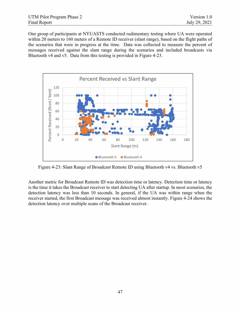
UTM Pilot Program Phase 2 Version 1.0 Final Report July 29, 2021
47
One group of participants at NYUASTS conducted rudimentary testing where UA were operated within 20 meters to 160 meters of a Remote ID receiver (slant range), based on the flight paths of the scenarios that were in progress at the time. Data was collected to measure the percent of messages received against the slant range during the scenarios and included broadcasts via Bluetooth v4 and v5. Data from this testing is provided in Figure 4-23.
Figure 4-23: Slant Range of Broadcast Remote ID using Bluetooth v4 vs. Bluetooth v5
Another metric for Broadcast Remote ID was detection time or latency. Detection time or latency is the time it takes the Broadcast receiver to start detecting UA after startup. In most scenarios, the detection latency was less than 10 seconds. In general, if the UA was within range when the receiver started, the first Broadcast message was received almost instantly. Figure 4-24 shows the detection latency over multiple scans of the Broadcast receiver.

UTM Pilot Program Phase 2 Version 1.0 Final Report July 29, 2021
48
Figure 4-24: Broadcast Remote ID Detection Latency
4.4.1.2 VT-MAAP
Broadcast Remote ID was demonstrated at the VT-MAAP test site using ANRA Technology’s Remote ID transmitter mounted on a DJI Inspire 2, a smart-phone receiver application, and a laptop for Remote ID package capture and signal strength measurements.
The transmitter consisted of an internal lithium battery, system-on-chip computer with Wi-Fi adapter, and a Global Positioning System (GPS). It was fully independent from the aircraft in terms of power, GPS, and communication. The transmitter broadcasted on channel 6 in the 2.4 Gigahertz (GHz) ISM band, using the Wi-Fi Aware protocol. Wi-Fi Aware is the industry standard Wi-Fi protocol described in the ASTM Specification for Remote ID [3] for use with Broadcast Remote ID using Wi-Fi.
The smartphone receiver was a Google Pixel 2 smartphone running ANRA’s Broadcast Remote ID application. This device was used because it was one of the few smart-phones capable of Wi-Fi at the time. The app shows the current position of the phone as well as the location and breadcrumb trail of broadcast Remote ID targets. To get details on a target, the user must tap the icon of the target. Figure 4-25 shows the ANRA Broadcast Remote ID App.

UTM Pilot Program Phase 2 Version 1.0 Final Report July 29, 2021
49
Figure 4-25: ANRA Broadcast Remote ID App
A laptop was used to record Received Signal Strength Indication (RSSI) data and was co-located next to the smartphone. The laptop was a Lenovo 4389w44 with a Broadcom Wi-Fi card that uses antennae built into the display housing. The laptop was configured to log data from the Remote ID transmitter by filtering channel 6 and the transmitter’s Basic Service Set Identifier (BSSI).
The Broadcast Remote ID transmitter’s range was tested successfully out to a maximum visual range of 3,000 feet from the Remote ID receiver. There was some intermittent behavior, loss of signal, and significant latency at times. The range was tested by starting the UA as close as possible to the receiver at an altitude of 150 feet AGL. The UA was then flown outbound in 250 feet increments. The UA was stopped at each increment (time and range was noted) and the receiver’s reception was checked. The test stopped at 3,000 feet due to lack of visibility beyond of the UA after that point. The UA was flown back inbound using the same increments and performing the same checks. The RSSI-to-range measurements were also captured during these outbound and inbound flights. The average receive power was measured on the laptop over a 1-second period while stopped at increments. Figure 4-26 shows the RSSI-to-range measurements and compares the actual to the predicted values (estimated free-space path loss with the specifications from the system description).

UTM Pilot Program Phase 2 Version 1.0 Final Report July 29, 2021
50
Figure 4-26: Broadcast Remote ID Measured RSSI as a Function of Range
4.4.2 Findings and Recommendations
Table 4-10 contains Remote ID findings and recommendations that were compiled from the test sites and other participating stakeholders.
Table 4-9: Remote ID Findings and Recommendations
Remote ID Area
Findings/Recommendations
Display For the Remote ID Display applications, further investigation and development is needed to determine:
• How to properly credential public safety display clients? • How to properly credential public safety users of Remote ID? • How to manage Personally Identifiable Information (PII) exchanges/uses
among the various entities involved in an Remote ID exchange?
Broadcast Bluetooth v5 was more reliable than Bluetooth v4 at detecting, classifying, or identifying fast-moving UA.
Broadcast To ensure adequate reliability for intended Remote ID uses, production hardware designs will require careful attention to Radio Frequency (RF) link budgets, antennae patterns and placement, etc.
Broadcast Broadcast Remote ID worked well up to distances where the UA was hardly visible by the human eye. The update rate of the UA’s location was in order of 5-10 seconds

UTM Pilot Program Phase 2 Version 1.0 Final Report July 29, 2021
51
Remote ID Area
Findings/Recommendations
instead of the expected 1 second. Despite the delay, position updates appeared correct and were helpful in identifying and tracking UA movement.
Broadcast Future Broadcast Remote ID testing could include spectral analysis of operational environments and detailed logging of data packet transmission and receipt.
Network In general, industry participants provided feedback indicating their assessment that ASTM Network Remote ID as defined in the standard can work in an operational environment and support stakeholder needs.
Network Thorough automatic testing of Network Remote ID Service and Display Providers would help ensure interoperability and compliance to the standard.
Enhanced Details
For accessing enhanced details, further investigation is needed to determine which data is required at which access level, and how user’s access levels are verified. This finding is also applicable to the FAA’s data correlation capabilities.
General Test and demonstration of Remote ID should be continued. Due to COVID-19, the participation by public safety officials was reduced. Further testing should try to increase this interaction to gain more perspective on how Remote ID will be used.
4.5 Support of Message Security
The section below describes the of the message signing and identity management demonstration conducted in UPP2. The FAA used UPP2 to enhance the protections of data exchanges in the UTM environment, implemented in the form of digitally signed messages. In short, a cryptographic algorithm was applied to the information being transmitted, creating a digital signature that was appended to the message. The signature creation relied on a type of cryptography, known as public key cryptography, which uses public-private key pairs to create and validate the signatures, as shown in Figure 4-27.
Figure 4-27: Basic Overview of Digital Signing and Validation in UPP2

UTM Pilot Program Phase 2 Version 1.0 Final Report July 29, 2021
52
UPP2 created and validated digital signatures by test site partners and the FAA to protect the following data:
1. Contents of messages between USSs, third-party providers, and the FAA.
2. Access token requests from USSs, third-party providers, and the FAA.
3. Access tokens.
All data were signed using technical requirements that were determined to be achievable by all demonstration participants [12]. Each participating entity either was provided with or generated a public-private key pair to create and validate digital signatures. The private key was verified to be held only by the entity that created the signature. All of the participants’ public keys were stored in a public repository and used by message recipients to verify the signature was created by the sender of the message.
In the message exchange as defined by the ASTM API, participants can request information, notify other participants of information, report their operational area to the DSS, or remove their DSS data. With each type of message, metadata is included in headers and message contents may also be included in a body. The contents of the message are signed, and the signature is appended to the message. In general, when receiving a signed message, token request or token, the receiving entity would verify the signature. The verification process used the public key of the sender to verify their identity along with the validity of the certificate used for signing.
The use of digital certificates established trust between communicating participants in UPP2 by associating a specific entity with a cryptographic key pair. The digital certificates used in UPP2 were issued by a prototype FAA CA. The issuance process involved an initial request to the FAA for the signing certificate, basic identity verification of the certificate requestor by FAA personnel, the creation of the certificate, and finally delivery to the participant.
In the UPP2 environment, OAuth 2.0-compliant access tokens ensured that each information exchange occurs between properly authorized participants. In UPP2, the token request was secured using a digitally signed message. The token request included the scopes requested for each application function which limit the operational action that can be taken using the token. The request also included an audience, or “aud” claim, specifying the entity to which the message would be sent. Once the authorization server validated the signature and verified the access of the participant, it issued a token. When sending a message, the sender appended the access token to the message and the receiver used this token as proof of authorization.
4.6 Information Queries and Correlation
UPP2 demonstrated information queries that fall into three categories: Correlation Query, Historical Query, and Network Remote ID Query. The Correlation Query returned data from simulated FAA sources, such as Low Altitude Authorization and Notification Capability (LAANC) and DroneZone, based on query input(s) obtained via Broadcast Remote ID. The Historical Query returned Operation Intent data from USSs. The Network Remote ID Query returned Remote ID data using Network Remote ID as detailed in the ASTM Specification for

UTM Pilot Program Phase 2 Version 1.0 Final Report July 29, 2021
53
Remote ID [3]. Table 4-10 highlights the key metrics for data collection to assess information query methods and supporting services/technologies.
Table 4-10: Information Query Metrics
PA ID PA Title Description MOE Supported
UTM-PA-07 Remote ID data exchange performance
What is the performance of Remote ID data exchanges (broadcast, lookups, etc.), broken down by various categories? E.g., Categories:
• UA Broadcast to Remote ID App (if possible)
• Display Provider to Service Provider • UAS to Service Provider
UTM-MOE-2
UTM-PA-08 Historical data query performance
What is the performance of Historical Data Query exchanges, broken down by various categories? E.g., Categories:
• FIMS-USS Queries • Public Safety Queries
o Initiated by third party o FAA-Initiated
UTM-MOE-5
UTM-PA-09 USS network data exchange performance
What is the performance of USS network data exchanges, broken down by various categories? E.g., Categories:
• USS to Discovery (DSS) • Operation Intent • Constraints
UTM-MOE-4
4.6.1 Correlation Query
The Correlation Query allows authorized users to receive additional details from the FAA based on Broadcast Remote ID data received from a UA. The Correlation Query focused on the FAA or public safety entities’ need for other FAA-held data (e.g., registration data, airspace authorizations) that correlates to data those entities received via Remote ID broadcast. The FAA used a set of simulated FAA data sources and the IDIAS component of FIMS exposed a query endpoint, via a REST API, to the FAA and public safety entities. The simulated data sources included LAANC, DroneZone, Integrated Airman Certification and Rating Application (IACRA), Traditional Airman Certification Registration (TACR), and UA Sightings Reports. The IDIAS component took the query input (Broadcast Remote ID data) and queried the simulated data sources for data corresponding to the query input. Figure 4-28 highlights the data exchanges of the Correlation Query.

UTM Pilot Program Phase 2 Version 1.0 Final Report July 29, 2021
54
Figure 4-28: Correlation Query Data Exchanges
For UPP2, the aircraft registration number was used as the query input. The prototype broadcast modules used in UPP2 used registration numbers as the UAS ID, so the IDIAS prototype was configured to align with the use of registration numbers. The ASTM Specification for Remote ID [3] allowed registration numbers as an option for the UAS ID. The Correlation Query demonstrates the concept of querying for corresponding FAA data based on Broadcast Remote ID data. The images below show notional information returned by the Correlation Query. Figure 4-29 shows an FAA-led query conducted via the FIMS Admin Portal; Figure 4-30 shows a third-party mobile application used by a public safety entity. The data returned by the Correlation Query was for test and demonstration purposes and did not contain any actual PII. Mock data was used in all PII fields.

UTM Pilot Program Phase 2 Version 1.0 Final Report July 29, 2021
55
Figure 4-29: Admin Portal Correlation Query
Figure 4-30: Correlation Query from Third-Party

UTM Pilot Program Phase 2 Version 1.0 Final Report July 29, 2021
56
4.6.2 Historical Query
The Historical Query focused on the FAA’s ability to get historical operation intent data from USSs. The ASTM Draft Specification for UTM [4] (in draft form during the timeframe of UPP2) did not support getting historical operational data. For UPP2, a new data flow was prototyped to allow a 4D geographical query to a USS for operations. The Historical Query process was initiated from the Admin Portal and each USS was queried for operations within the 4D geographical area. This basic Historical Query demonstrated the concept of getting data from USSs.
UTM-PA-08 (Historical Data Query Latency) aimed to capture latency information for the data exchanges involved in the Historical Query process. The exchange initiator captured the time between when it sent a request and when it received a response, and provided information for data analysis. The requests are categorized as: Admin Portal, Operations 4D Query, and Operations GET. The Admin Portal category covers the entire Historical Query process from initiation until all USSs have been queried. The Operations 4D Query category covers a 4D query to an individual USS. The Operations Get category covers an induvial request for Operation Intent details from a USS. Figure 4-31 and Figure 4-32 show the 95th percentile latency and sample count of each category as captured during each test site’s demonstration. This metric shows that, 95% of the time, the exchange occurs faster than the stated latency and is intended to inform requirements and design moving forward.
Figure 4-31: Historical Query Latency – NYUASTS

UTM Pilot Program Phase 2 Version 1.0 Final Report July 29, 2021
57
Figure 4-32: Historical Query Latency – MAAP
4.6.3 Network Remote ID Query
The Network Remote ID Query focused on Network Remote ID display providers getting data from Network Remote ID service providers as detailed in the ASTM Specification for Remote ID [3]. This Network Remote ID functionality was demonstrated as a part of UPP2, but Network Remote ID has since been removed from the FAA’s Remote ID rule.
A Network Remote ID service provider is a logical entity denoting a UTM system or comparable UAS flight management system that participates in Network Remote ID and provides data for and about UAS it manages. A Network Remote ID display provider is a logical entity that aggregates Network Remote ID data from potentially multiple Net-RID service providers and provides the data to a display application (i.e., an app or website). This prototype exchange used the API developed in the ASTM Specification for Remote ID [3] . The API allowed a display provider to submit a request to a service provider with a specific geographic area. Service providers responded with data from Network Remote ID UAS within that area. Once a UA was identified, the display provider submitted another request using the identifier of the UA to get more details. This feature was demonstrated by AirMap, AiRXOS, ANRA, AX Enterprize, OneSky, Wing, and the FAA using the Admin Portal.
The PA UTM-PA-07 Remote ID Exchange Performance – Network (Display to Service Provider) aimed to capture latency information for the data exchanges between the display and service providers. The service provider captured the time it sent a request and when it received a response and provided information for data analysis. Figure 4-33 shows the 95th percentile latency and sample count of the initiating USS. This metric shows that, 95% of the time, the display to service provider exchange occurs faster than the stated latency and is intended to inform requirements and design moving forward.

UTM Pilot Program Phase 2 Version 1.0 Final Report July 29, 2021
58
Figure 4-33: Remote ID Display Interaction Latency
4.6.4 Findings and Recommendations
Table 4-11 contains information query findings and recommendations compiled from the test sites and other participating stakeholders.
Table 4-11: Information Query Findings and Recommendations
Information Query
Findings/Recommendations
Correlation Query The Correlation Query prototype using the IDIAS component of FIMS and simulated FAA data sources was a success. The query initiation was demonstrated using both the Admin Portal and an external third-party, via an API. Potential future investigation, design, and development areas include: • Establishing data exchange requirements for external service provider
communications with FIMs for correlation queries. • Ability of FIMS to receive/verify credentials of the entity submitting a
query and return correlation results based on entity’s data access permissions. Areas for consideration may include Role Based Access Control, User Security, handling of PII data, etc.
Historical Query The Historical Query prototype was successful and proved the concept of getting historical data from USSs. The Historical Query concept needs further consideration between the FAA and Industry to achieve a long-term solution that is acceptable to both parties. Key areas to investigate include: • What are the applicable use cases for historical queries? • How are historical queries bound?

UTM Pilot Program Phase 2 Version 1.0 Final Report July 29, 2021
59
Information Query
Findings/Recommendations
• What data is necessary in a historical query and how long is that data expected to be available for historical queries (e.g., Operation Intent, Telemetry, etc.)?
• What are the practical exchange mechanisms? • How do historical queries influence data retention and privacy policies?
4.7 Public Safety Operations
4.7.1 Overview
Early in the development of UTM, the FAA recognized an immediate need to expand and address the role of UTM in enabling security partners to provide for the safety of the public. Public safety and security is a key focus area that supports the full implementation of Remote ID and lays the foundational elements for future expansion of UTM operations and associated rules.
Note: Web/mobile applications utilized throughout UPP2 to support public safety interests were for demonstration and research purposes. These applications may not be implemented as a direct service from the FAA, but results may be used to refine application and services requirements for the larger UTM community.
Although participation of public safety stakeholders was limited during UPP2 demonstrations due to the COVID-19 pandemic and associated travel impacts, survey results and direct participation were used to incorporate public safety stakeholder needs. Evaluation of public safety needs are highlighted throughout the findings of this report, however Table 4-12 and Table 4-13 provide a summary of the participants, followed by the performance attributes utilized to measure and gain insight from this critical stakeholder group.
Table 4-12: UPP2 Public Safety Participants
VT-MAAP NYUASTS
• Christiansburg Police Department • Blacksburg Police Department • Virginia Tech Police Department • Montgomery County Sheriff’s
Department • Virginia Tech Department of Emergency
Management
• Syracuse Fire Department • Oneida County Sheriff’s Department • Albany County Sheriff’s Department

UTM Pilot Program Phase 2 Version 1.0 Final Report July 29, 2021
60
Table 4-13: Performance Attributes
PA ID PA Title Description MOE Supported
UTM-PA-10 Survey Assessments Feedback on various aspects UTM operations and project execution.
UTM-MOE-4
UTM-PA-12 Priority Operations Feedback and opinions of the current priority operation capabilities provided by the ASTM Draft Specification for UTM [4]. Note: Captured using qualitative survey questions.
UTM-MOE-3
4.7.2 Outcomes
4.7.2.1 VT-MAAP
During the demonstrations, public safety representatives from local law enforcement and emergency management participated in Use Cases 3 and 5, public safety UAS operating within a UVR and queries for historical UTM information.
Feedback gathered from public safety personnel indicated that a UVR could be useful in various public safety situations, including search and rescue, criminal search and apprehension activities, special event security, damage assessments, traffic crashes and other critical incidents where airspace needs to be temporarily reserved.
Public safety personnel feedback on Remote ID queries and display of compliance details was largely positive, especially the enhanced operator information including operator location and phone number. General feedback included improvements such as, a less restrictive display limit, color coding of different aircraft and easy screen capture mechanisms built into the Remote ID applications.
4.7.2.2 NYUASTS
Similarly, at NYUASTS, demonstration of Use Cases 3 and 5 was completed successfully. Participants acted in roles as UAS operators for public safety operations as well as UVR and Remote ID observers utilizing display tools for situational awareness. During which, several scenarios were used to demonstrate public safety UTM capabilities.
Sheriff personnel utilized multiple USSs to enter UVR operational information while, situational awareness displays of Remote ID operations were completed with the AX Enterprize USS for Remote ID queries. AX Enterprize created a specific USS rule that allowed public safety flights to be flown within a UVR that was also denoted as public safety. Public safety personnel were also able to execute a Correlation Query and obtain registration information in the field using the AX Enterprize mobile application, which successfully returned correlated UAS and pilot registration information.

UTM Pilot Program Phase 2 Version 1.0 Final Report July 29, 2021
61
4.7.3 Findings and Recommendations
Table 4-14 contains public safety operations findings and recommendations that were compiled from the test sites and other participating stakeholders.
Table 4-14: Public Safety Operations Findings and Recommendations
Area Findings/Recommendations
Survey Assessments Qualitative survey data across both VT-MAAP and NYUASTS indicated demonstration activities were largely successful. Correlated information displaying name and phone number were well received. Some feedback from stakeholders included a desire for a less restrictive display limit, color coding of different aircraft and easy screen capture mechanisms built into the Remote ID applications.
Priority Operations Feedback on UVRs from public safety surveys indicated that the capabilities demonstrated would prove to be useful in various public safety situations involving UAS operations. Metrics utilized to measure overall satisfaction of UVR capabilities such as, usefulness of information, conciseness, level of detail, and accuracy all indicated that participants were satisfied with the UVR capabilities demonstrated during the events.
4.8 Off-Nominal/Contingent Events
UPP2 demonstrated off-nominal events for nonconforming and contingent operations as well as crewed aircraft in the area of an operation. Key capabilities demonstrated included USS conformance monitoring and crewed aircraft detection and alert. Table 4-15 highlights the key metrics for data collection to assess off-nominal identification/notification methods and supporting services/technologies.
Table 4-15: Off-Nominal/Conformance Metrics
PA ID PA Title Description MOE Supported
UTM-PA-02 Operation conformance
Are operations staying within their conformance parameters during UPP2 activities?
UTM -MOE-1
4.8.1 USS Conformance Monitoring
Conformance monitoring is a USS service that determines whether a UA is in conformance with its operation intent and takes appropriate actions when it is not. Conformance monitoring is an essential service for UTM and enables BVLOS operations. The FAA UTM ConOps Version 2.0 [5] describes how USS conformance monitoring can help enable BVLOS operations:

UTM Pilot Program Phase 2 Version 1.0 Final Report July 29, 2021
62
UTM BVLOS Operators must be capable of tracking their vehicle and remaining within the bounds of their shared intent volumes. USSs can assist Operators in meeting this requirement through vehicle tracking and conformance monitoring services whereby UAS
transmit near-real time tracking data to the USS, so the USS can provide services that enable Operators to monitor the UA’s position and conformance to applicable system-based Operation Volume boundaries during BVLOS portions of flight. USSs may also use conformance monitoring to track Operator conformance to the geographical boundaries specified in the Performance Authorization.
Operation intent is changed to a nonconforming state if the UA is determined to be outside of its current operation intent. The operation intent volumes are updated to cover where the aircraft is projected to travel in the near future and the updated operation intent is shared with other USSs. Operation intent is changed to a contingent state due to a timeout from a nonconforming state or due to operator initiation of a contingency. The operation intent volumes are replaced with one or more new volumes that encompass projected trajectories based on available information (e.g., position, heading, speed, wind data), capturing where the UA may be located out to some specified point in time; this contingency volume is shared as an updated operation intent with other USSs for situational awareness and to help inform potential actions by nearby/affected UTM operations. Conformance monitoring is described in detail in the ASTM Draft Specification for UTM [4].
For UPP2, conformance monitoring was implemented by all participating USSs. For the demonstration, the USSs utilized a 30-second timeout for transitioning from the nonconforming or contingent operational states. Conformance monitoring was demonstrated by having UA intentionally perform actions that caused their operation states to transition to non-conforming and/or contingent. There were also instances of unintentional non-conforming or contingent operations for various reasons during UPP2. Figure 4-34 shows the SAFIRE-X display used by NYUASTS and shows three off-nominal events. The yellow volume is UAS 2 in a nonconforming state. There are two orange contingent volumes; one was intentional [UAS 5] while the other was due to poor UAS ground positioning [UAS 1].

UTM Pilot Program Phase 2 Version 1.0 Final Report July 29, 2021
63
Figure 4-34: Nonconforming and Contingent UAS at NYUASTS
4.8.2 Crewed Aircraft Detection and Alert
Crewed aircraft detection and alert was demonstrated using ACAS-sXu integrated with a UAS and also with a SDSP via a Ground-Based Radar System (GBRS) and a ground-based Automatic Dependent Surveillance-Broadcast (ADS-B) receiver. For more information about ACAS-sXu see the ASTM Standard Specification for Detect and Avoid System Performance Requirements [13].
4.8.2.1 VT-MAAP
VT-MAAP demonstrated the SDSP providing radar and ADS-B integrated with the ANRA USS for processing, display, and notifications or alerts. The radar used was the SRC R1400 and the ADS-B receiver was an uAvionix pingStation. The ANRA USS allows the UAS pilot to set a warning distance with setting up the UAS profile and the pilot is alerted based on the warning

UTM Pilot Program Phase 2 Version 1.0 Final Report July 29, 2021
64
distance configured. Figure 4-35 shows the ANRA USS display during notification of a possible collision with a crewed aircraft. The UA is shown as a green circle. The intruder is represented as both an airplane icon (ADS-B position) and a blue arrow (radar position).
Figure 4-35: ANRA USS Display Notification of a Crewed Aircraft
4.8.2.2 NYUASTS
NYUASTS demonstrated ACAS-sXu detect and avoid capability integrated with a live UAS. The ACAS algorithms utilized a “remain well clear” buffer of 2,500 feet horizontal and 250 feet vertical. The flight configurations were selected such that the ACAS system would provide UAS pilot guidance due to breaching the ACAS minimum 250 feet altitude separation. ACAS alerts are provided to the pilot as “guidance.” ACAS is not integrated with the UAS GCS nor does it automatically execute any maneuvers. ACAS guidance always instructed the UAS pilot to “descend” and/or “turn left or right” (based on the position of the UAS to the crewed aircraft in our encounters). Figure 4-36 shows ACAS pilot guidance (on the left) with the NYUASTS display SAFIRE-X (on the right). ACAS is indicating to the pilot to move left and down (away from the crewed aircraft path).

UTM Pilot Program Phase 2 Version 1.0 Final Report July 29, 2021
65
Figure 4-36: ACAS sXu Pilot Guidance
4.8.3 Findings and Recommendations
Table 4-16 contains off-nominal/contingency event findings and recommendations that were compiled from the test sites and other participating stakeholders.
Table 4-16: Off-Nominal/Contingency Event Findings and Recommendations
Area Findings/Recommendations
Operator Notification
Test site partners found that the ASTM Draft Specification for UTM [4] provides mechanisms and information for sharing of operational state but does not currently impose requirements on notifications for operators. Additional requirements may be needed to address the operator awareness and support informed responses.
Operator Interface Demonstrated technologies can be applicable to production systems; however, continued improvements to interfaces and possible GCS logic could reduce instances of avoidable off-nominal events. Better user interfaces and notifications could help avoid unintentional non-conformance events due to early takeoffs or remaining in-air past the end time for an operator’s 4D operation intent (e.g., close-out time for last operation volume segment in a BVLOS operation).
Conformance Monitoring
Participating USSs and operators fount that the 30 second timeout for returning to conformance before going contingent was too short in many cases. In various instances, RPICs found that their control set-ups took longer than 30 seconds to change the operating mode of the UAS so they

UTM Pilot Program Phase 2 Version 1.0 Final Report July 29, 2021
66
Area Findings/Recommendations could manually fly it back into a conforming position. Some RPICs also found that it would take longer to re-plan a flight trajectory as well, if necessary to bring it back into conformance. Participants noted a time out in the range of 120 seconds would be preferable to reduce occurrences of a contingent state.
Operator Training Unintentional off-nominal events were largely due to operator errors in planning/initiating operations or due to issues interfacing the UASs with the USS software (e.g., sending GPS MSL altitudes when the software was expecting WGS-84). These issues are not caused by the UTM concept or the ASTM Draft Specification for UTM [4]. Rather, they serve to highlight the importance of operator training, requirements definition, application of standard/common data requirements where appropriate/needed (e.g., altitude reference), and testing of associated system interactions.

UTM Pilot Program Phase 2 Version 1.0 Final Report July 29, 2021
67
5 Conclusion
The FAA Extension, Safety, and Security Act of 2016, Section 2208(b)(1) [1] directed the Administrator to establish a UTM pilot program. Since the initiation of the FAA UPP in 2017, two successful phases of testing and demonstration activities have proven the FAA’s, NASA’s, UAS test sites’, and industry partners’ ability to implement an agile approach to capability development. Through this process, UPP has:
• Met the requirements specified by Congress in the FAA Extension, Safety, and Security Act of 2016 [1] and the FAA Reauthorization Act of 2018 [2].
• Expanded upon the FIMS10 capabilities during each phase of UPP activities.
• Enabled collaborative development of maturing ideas and concepts for UTM, transforming them into initial operating capabilities being prepared for deployment to support commercial BVLOS operations.
• Provided test results and feedback to industry and standards bodies to facilitate continued maturation of the UTM ecosystem, which will support expansion of initial operating capabilities as commercial BVLOS operations become routine and operating densities continue to increase.
In coordination with NASA and industry, an initial infrastructure for the UTM ecosystem was established via UPP1 demonstration activities followed by enhancement and expansion of the UTM framework in UPP2. With the closing of UPP, the FAA and its partners have completed an end-to-end proof-of-concept of the UTM infrastructure. Per the Agile capability process shown in Figure 5-1, tested and demonstrated UTM functions meeting success criteria and required for near term implementation will be transitioned to downstream stakeholders. Challenges, gaps, and lessons learned identified during testing will be utilized to support continued maturation of standards, identification of procedural and process changes, inform future rulemaking, and to prioritize future infrastructure and processes for planned USS services. Changes resulting from lessons learned will provide refinement to UTM architecture and services to ultimately support the full range of increasingly complex UAS operations—from remotely piloted aircraft to command-directed UAS and highly automated (i.e., autonomous) UAS performing BVLOS operations.
10 The FIMS prototype was initially developed during UTM RTT TCL activities. The prototype was transferred from NASA to FAA prior to the initiation of UPP and was integrated into demonstration platforms for testing of new and matured capabilities during UPP activities.
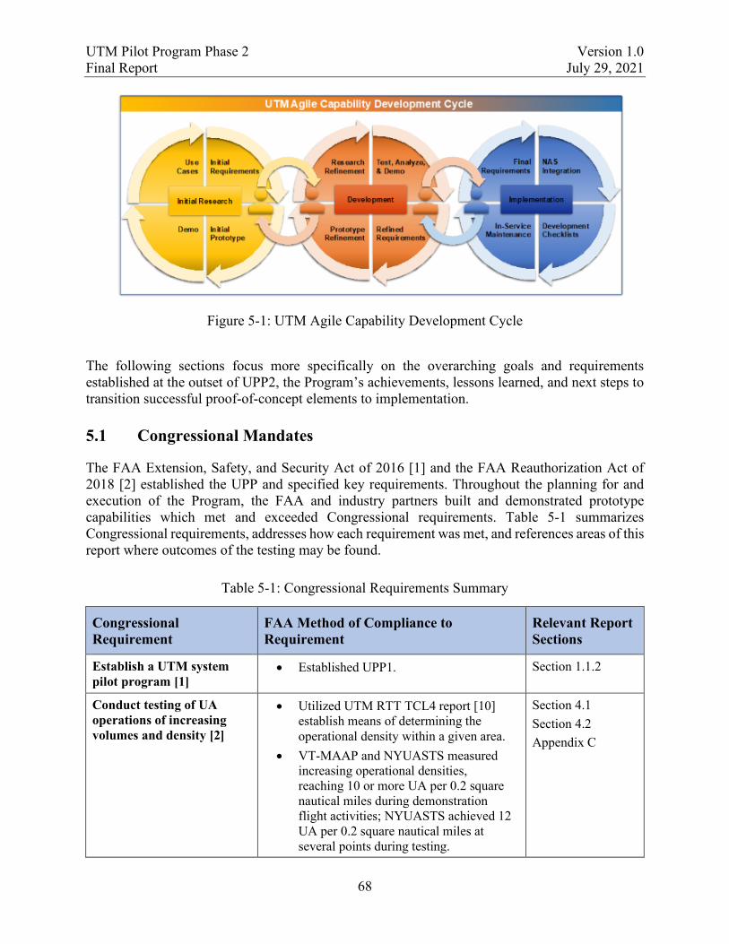
UTM Pilot Program Phase 2 Version 1.0 Final Report July 29, 2021
68
Figure 5-1: UTM Agile Capability Development Cycle
The following sections focus more specifically on the overarching goals and requirements established at the outset of UPP2, the Program’s achievements, lessons learned, and next steps to transition successful proof-of-concept elements to implementation.
5.1 Congressional Mandates
The FAA Extension, Safety, and Security Act of 2016 [1] and the FAA Reauthorization Act of 2018 [2] established the UPP and specified key requirements. Throughout the planning for and execution of the Program, the FAA and industry partners built and demonstrated prototype capabilities which met and exceeded Congressional requirements. Table 5-1 summarizes Congressional requirements, addresses how each requirement was met, and references areas of this report where outcomes of the testing may be found.
Table 5-1: Congressional Requirements Summary
Congressional Requirement
FAA Method of Compliance to Requirement
Relevant Report Sections
Establish a UTM system pilot program [1]
• Established UPP1. Section 1.1.2
Conduct testing of UA operations of increasing volumes and density [2]
• Utilized UTM RTT TCL4 report [10] establish means of determining the operational density within a given area.
• VT-MAAP and NYUASTS measured increasing operational densities, reaching 10 or more UA per 0.2 square nautical miles during demonstration flight activities; NYUASTS achieved 12 UA per 0.2 square nautical miles at several points during testing.
Section 4.1 Section 4.2 Appendix C

UTM Pilot Program Phase 2 Version 1.0 Final Report July 29, 2021
69
Congressional Requirement
FAA Method of Compliance to Requirement
Relevant Report Sections
• Utilized ASTM Draft Specification for UTM [4] for coordination and deconfliction between UAS operations within high density operating environments.
Conduct testing of various remote identification and tracking technologies [2]
• Utilized ASTM Specification for Remote ID [3], which establishes performance requirements for UAS Remote ID technologies and services.
• MAAP and NYUSASTS demonstrated Remote ID data exchange performance (broadcast, lookups, etc.) – UA position information and identification was successfully transmitted.
Section 4.4
Permit blanket waiver authority for participating operators where possible under noted conditions [2]
• Test sites had requisite waivers/Certificate of Authorization (COA)s in place to support the operations necessary for UPP2 demonstrations.
Section 2.3.1
In addition to the requirements established by Congress; the FAA, NASA, and industry partners incorporated supplemental requirements for testing and demonstration that support near and longer-term needs for the UTM ecosystem. The results of these demonstrations are captured throughout Section 4.0, and a summary of the outcomes will be described in the following section.
5.2 Summary of Findings and Recommendations for UPP2
UPP2 was successful in examining a variety of end-to-end UTM functionalities and gathering information necessary to support initial implementation activities. While many aspects of UPP were successful, as with any demonstration of this nature areas of potential future enhancements or improvements on the process were identified. UPP partner teams provided feedback on lessons learned through the development and demonstration activities, and program-level lessons learned were also collected.
5.2.1 High Density Operations
The following is a summary and recommendations from Section 4.1.
Summary: UPP2 high density operational testing leveraged the findings of NASA’s UTM RTT TCL4 report [10] as the defining goal. UPP test site partners successfully conducted demonstration activities with operational densities of 10 or more UA per 0.2 square nautical miles during demonstration flight activities.

UTM Pilot Program Phase 2 Version 1.0 Final Report July 29, 2021
70
Recommendations: Increasing density of operations served as a valuable tool for stress testing various functionalities and interoperability requirements within a cooperative traffic management ecosystem such as UTM. For example, approaches to strategic deconfliction at the time of testing presented challenges to maintaining high-density operating environments. Given altitude restrictions for UAS operations (400 feet AGL) combined with the ASTM Draft Specification for UTM [4] of 95% containment error bounds, capacity of the airspace was limited and deconfliction was complicated. Additional requirements development/testing, followed by industry evaluations in live-flight environments, will support continued improvement to capacity and efficiency of UA operations in a given airspace.
5.2.2 UAS Volume Reservation (UVR)
The following is a summary and recommendations from Section 4.2.
Summary: UPP2 test goals to demonstrate UVRs were intended to determine the data exchange performance across the network, such as gathering and transmittal of operational intent, and the performance of data transmission from USS to DSS. During the demonstrations of the UVR prototype capability, USS network participants successfully proved interoperability of the system in transmitting, displaying, and notification of distributed and overlapping UVR information. Additionally, public safety stakeholders found the capability to have value in supporting potential public safety scenarios.
Recommendations: In the near term, additional development and refinement of the UVR capability is needed, including permissions and business rules required to utilize UVRs, availability of relevant contextual UVR information, and improving how the information is transmitted, accessed, and displayed. Continued conceptual and policy efforts are needed to determine requirements that address these gaps.
5.2.3 Strategic Deconfliction Approaches
The following is a summary and recommendations from Section 4.3.
Summary: The goal during UPP2 was to demonstrate strategic deconfliction via advanced planning and information exchange. Both MAAP and NYUASTS partners utilized the ASTM Draft Specification for UTM [4] and its standard API for sharing of operation intent11 as the benchmark for testing where able. Generally, demonstration of strategic deconfliction approaches were successful. The approaches broadly included coordination between UAS operators via USS-to-USS data exchanges, and strategic deconfliction where operational overlaps occurred. Recommendation: While both strategic deconfliction and network performance supporting data exchange showed success during demonstrations, some refinement is required to expand operational use of the deconfliction approaches and the system and software prototypes developed to support deconfliction. Current draft UTM standard requirement of 95% containment presented
11 USS message exchange in UPP2 used version 0.3.5 of the utm.yaml from the implementation 2020Q2 branch of the astm-utm github repository.

UTM Pilot Program Phase 2 Version 1.0 Final Report July 29, 2021
71
– challenges as it was often hard to achieve both deconfliction and a high-density environment given the altitude constraints currently imposed on UAS operations.
• Temporal Deconfliction – Temporal deconfliction was not utilized due to its impact on operational density. Future test/demonstration activities could focus on evaluating and quantifying operating densities where temporal separation is viable, to better inform performance requirements for strategic deconfliction.
• Altitude Reference – Test site stakeholder systems/software interface prototypes utilized different frames of altitude reference which required USS and/or operator conversions. Future updates to industry services, standards, etc. should support USS communication of altitude in a manner that facilitates interoperability (e.g., use of WGS84 ellipsoid as a datum).
• Information Sharing and Conflict Detection – USS demonstration software prototypes provided limited information to the operator. Demonstration results show that additional contextual information for operators is needed for full deconfliction information sharing to be realized. Further development by industry is needed so that USS software may fully implement automated means of sharing information.
5.2.4 Remote Identification (Remote ID)
The following is a summary and recommendations from Section 4.4.
Summary: UPP2 goals for Remote ID were to demonstrate system performance in providing certain identification, location, and UA performance information that people on the ground and other airspace users can receive. The ASTM Specification for Remote ID [3], which details performance requirements for UAS Remote ID technologies and services was utilized as the benchmark for flight test demonstrations. Overall, prototypes tested were able to successfully transmit broadcast Remote ID information at distances where the UA was difficult to visibly detect, up to 3,000 feet. Additionally, industry participants provided feedback indicating their assessment that ASTM Network Remote ID as defined in the standard can work in an operational environment and support stakeholder needs.
Recommendations: While the demonstration and research of the capability to broadcast Remote ID information was successful, the tests revealed several needed improvements requiring additional testing. Test site partners and stakeholders found that screen size should be adjusted, automatic testing of Remote ID providers is needed, Bluetooth V5 is more capable, production hardware designs require careful attention, and actual broadcast latency impacts, and considerations of spectrum analysis may need additional analysis for given areas. The demonstration of the capability to broadcast Remote ID revealed efficacy across the prototype services; however, additional testing may be required to optimize Remote ID broadcast capabilities. Automatic testing of Network Remote ID Service and Display Providers should be incorporated in future tests to ensure interoperability and compliance to the standard.

UTM Pilot Program Phase 2 Version 1.0 Final Report July 29, 2021
72
5.2.5 Support of Message Security
The following is a summary and recommendations from Section 4.5.
Summary: UPP enacted security measures to protect the information exchanges between the participants. UPP1 established a baseline for ensuring the authorization of participants using a central authorization server to issue access tokens that are required for any UPP communications. In addition, UPP1 required TLS protocols to be used for in-transit protection. UPP2 built upon those initial baselines to add digitally signed messages and a PKI which provided application layer protections for integrity, authentication, and non-repudiation.
Recommendations: Future implementers of UTM should consider security to be a critical enabler of the UTM concept. Participants must trust that the information they receive from other UTM participants has not been altered or corrupted. In addition, participants must trust the source of received data to use such data to inform operational decisions. The FAA, industry, standards bodies, and other UTM stakeholders should continue to evaluate the security needs for the UTM ecosystem to determine the appropriate protections for UTM data exchanges in the future.
5.2.6 Information Queries and Correlation
The following is a summary and recommendations from Section 4.6.
Summary: UPP2 demonstrated information queries within three categories: Correlation Query, Historical Query, and Network Remote ID Query. Each was demonstrated and tested with the purpose of determining the data exchange/query performance. The Correlation Query returned data from simulated FAA sources, such as Low Altitude Authorization and Notification Capability (LAANC) and DroneZone, based on query input(s) obtained via Broadcast Remote ID. The Historical Query returned operation Intent data from USSs. The Network Remote ID Query returned Remote ID data using Network Remote ID as detailed in the ASTM Specification for Remote ID [3] .
Recommendations:
• Correlation Query: The Correlation Query focused on the FAA or public safety entities’ need for other FAA-held data (e.g., registration data, airspace authorizations) that correlates to data those entities received via Remote ID broadcast. The Query prototype using the IDIAS component of FIMS and simulated FAA data sources was a success, and potential future investigation, design, and development areas include establishing data exchange requirements for external service provider communications, and the ability of FIMS to receive/verify credentials of the entity submitting a query and return correlation results based on entity’s data access permissions.
• Historical Query: This prototype demonstration and test was also a success. The demonstration aimed to capture latency information for the data exchanges involved in the Historical Query process. Key areas of improvement between the FAA and Industry should focus on applicable use cases, the bounds for historical queries, necessary data and

UTM Pilot Program Phase 2 Version 1.0 Final Report July 29, 2021
73
availability, exchange mechanisms, and policy concerns over how historical queries influence data retention and privacy.
5.2.7 Public Safety
The following is a summary and recommendations from Section 4.7.
Summary: Public safety input was gathered via survey data following demonstration activities. Feedback from public safety stakeholders largely indicated that prototype demonstrations were successful, with stakeholders finding much of the provided information from both correlation, and UVR prototypes to be useful.
Recommendations: As prototypes mature, additional participation from public safety stakeholders should continue to ensure end user needs are satisfied.
5.2.8 Off Nominal/Contingent Events
The following is a summary and recommendations from Section 4.8.
Summary: UPP2 Demonstration activities tested off-nominal events for nonconforming and contingent operations, as well as detection and alert of crewed aircraft in the vicinity of the operation using ACAS-sXu. Conformance monitoring was implemented by participating USSs and ACAS-sXu was integrated with a UAS and with an SDSP via a GBRS and a ground-based ADS-B receiver. Each system met the intended goal for the demonstration with nonconforming UA and aircraft being appropriately displayed to stakeholders.
Recommendations: UPP2 conformance, detection, and alert capability demonstrations successfully displayed conformance/non-conformance and alerting as needed. However, test sites noted that the service suppliers may need to improve prototype notifications and response requirements, and adjust timeout allowance from from 30 seconds to 120 seconds for returning to conformance. Additionally, better user interfaces could assist with unintentional non-conformance, while additional training may also alleviate unintentional off-nominal events.
5.3 UTM Pilot Program Closeout
Through testing of proof-of-concept prototype systems in simulated and live flight environments during both UPP phases, the basic functionality of FAA UTM systems and capabilities have been validated and are mature enough to transition to implementation for consideration as part of a set of UTM initial operating capabilities. With respect to near-term needs, data query/correlation capabilities tested during UPP2 will be used in deployment of FAA Remote ID Data Correlation services to support the FAA in responding to requests for information from authorized law enforcement and national security personnel. Beyond initial deployment, the results of UPP will be used to inform continued development of infrastructure , which will support rollout of UTM services necessary to enable routine BVLOS operations.
Participating industry stakeholders tested USS network architecture, deconfliction processes, and associated data exchanges to support BVLOS flights in increasingly dense operating

UTM Pilot Program Phase 2 Version 1.0 Final Report July 29, 2021
74
environments. While challenges and gaps remain, operations were conducted in higher density environments using the latest available standards, and valuable information and lessons-learned were obtained. Industry stakeholders can take these findings and data to appropriate organizations (e.g., standards bodies) to inform initial requirements and needs for routine BVLOS operations. This will lay the foundation for continued enhancements to support more complex operations in increasingly dense operating environments.
The results of UPP will be used to inform the UTM Implementation Plan and future rulemaking to enable routine BVLOS UAS operations.
5.4 Next Steps – Path to Implementation
Near Term – Per the FAA Remote ID Final Rule [14], the FAA will be able to correlate the serial number or session ID of a standard Remote ID UAS (or broadcast module) to the registration database, and will support requests for correlation of Remote ID data from authorized law enforcement and national security personnel. The information query and correlation capabilities tested in UPP2 will be used in development of this correlation service as part of implementation of the Remote ID final rule.
The test results and lessons learned during UPP will be used to inform near term activities and coordination between government and industry stakeholders on the topic of enabling routine BVLOS UAS operations in low altitude airspace, including:
• The BVLOS Advisory and Rulemaking Committee (ARC).
• The UTM Implementation Plan.
• The FAA UTM ConOps v3.0.
• The FAA BEYOND program.
• Continued maturation of standards relating to UTM operations
Long Term – The envisioned approach will continue to develop UTM to support routine, high density BVLOS UAS operations.

UTM Pilot Program Phase 2 Version 1.0 Final Report July 29, 2021
75
Appendix A UPP2 Aircraft
This appendix provides detailed regarding aircraft used by each test site in UPP2 demonstrations.
A.1 NYUASTS Aircraft Overview
Table A-2: NYUASTS Aircraft Overview
NYUAST A/C ID Platform NYUASTS Use Case Role Flight Type
N9232J Piper Cherokee Crewed Aircraft Crewed NY-UAS 1 DJI S1000 News BVLOS NY-UAS 2 DJI Phantom 4 Event Manager VLOS NY-UAS 3 DJI S1000 Public Safety BVLOS NY-UAS 4 DJI S900 Videographer BVLOS NY-UAS 5 Simulated UA Part 107 Recreational --- NY-UAS 6 DJI Matrice 200 Cinematography VLOS NY-UAS 7 Simulated UAS School Roof Inspection --- NY-UAS 8 DJI Matrice 200 Search and Rescue (land) VLOS NY-UAS 9 DJI Mavic Pro Traffic Monitoring VLOS NY-UAS 10 DJI Matrice 210 Security VLOS NY-UAS 11 DJI Mavic Pro Surveillance VLOS NY-UAS 12 DJI MG-1 Emergency Medical Delivery BVLOS NY-UAS 13 SAGA E450 On-Looker VLOS NY-UAS 14 Simulated UA Document Delivery --- NY-UAS 15 Microdrones MD4 Food Delivery VLOS NY-UAS 16 DJI Mavic Search and Rescue (water) VLOS

UTM Pilot Program Phase 2 Version 1.0 Final Report July 29, 2021
76
A.2 VT-MAAP Aircraft Overview
Table A-3: VT-MAAP Aircraft Overview
VT-MAAP A/C ID Platform VT-MAAP Use Case Role Flight Type12
VT-UAS 1 DJI Mavic Air 2 DJI Phantom 413
Media #1 VLOS
VT-UAS 2 DJI Inspire 2 Media #2 VLOS & BVLOS VT-UAS 3 DJI Inspire 2 Agricultural Survey VLOS VT-UAS 4 3DR Aero-M Environmental Assessment BVLOS VT-UAS 5 DJI Mavic Public Safety BVLOS VT-UAS 6 DJI M210 Public Safety BVLOS VT-UAS 7 DJI Inspire 1 Public Safety BVLOS VT-UAS 8 DJI Inspire 2 Public Safety BVLOS VT-UAS 9 DJI Mavic Building Inspection BVLOS VT-UAS 10 DJI Phantom 4 Hobbyist VLOS VT-UAS 11 DJI Mavic Railroad Inspection BVLOS VT-UAS 12 Hummingbird 7000 Package Delivery BVLOS VT-UAS 13 Simulated UA Package Delivery ---
12 Operations conducted at VT-MAAP and noted as BVLOS included true BVLOS and pseudo-BVLOS flight. Pseudo BVLOS flights were filed by a USS as BVLOS, and included use of deconfliction services, but flight was executed VLOS. 13 VT-UAS 1 utilized a Mavic Air 2 on 10/12/20 and 10/13/20, but due to compatibility issues, switched to a Phantom 4 for the remainder of the test.

UTM Pilot Program Phase 2 Version 1.0 Final Report July 29, 2021
77
A.3 UAS Platform Details
Table A-4: 3DR Aero-M
Type Fixed-Wing
Manufacturer / Model 3DR Aero-M Wingspan 74” Gross Weight 6.8 lbs
Max Endurance ~ 40 mins
Table A-5: DJI Inspire 1
Type Multi-Rotor
Manufacturer / Model DJI Inspire 1 Gross Weight 7.7 lbs Max Endurance ~ 15 mins
Max Speed 40 mph
Table A-6: DJI Inspire 2
Type Multi-Rotor
Manufacturer / Model DJI Inspire 2 Gross Weight 9.37 lbs Max Endurance ~ 27 mins
Max Speed 58 mph

UTM Pilot Program Phase 2 Version 1.0 Final Report July 29, 2021
78
Table A-7: DJI Matrice 200
Type Multi-Rotor
Manufacturer / Model DJI Matrice 200 Gross Weight 13.5 lbs Max Endurance ~ 30 mins
Max Speed 51 mph
Table A-8: DJI Matrice 210
Type Multi-Rotor
Manufacturer / Model DJI Matrice 210 Gross Weight 13.5 lbs Max Endurance ~ 38 mins
Max Speed 51 mph
Table A-9: DJI Mavic
Type Multi-Rotor
Manufacturer / Model DJI Mavic Gross Weight 2.2 lbs Max Endurance ~ 30 mins
Max Speed 45 mph

UTM Pilot Program Phase 2 Version 1.0 Final Report July 29, 2021
79
Table A-10: DJI Mavic Air 2
Type Multi-Rotor
Manufacturer / Model DJI Mavic Air 2 Gross Weight 1.26 lbs Max Endurance ~ 34 mins
Max Speed 42 mph
Table A-11: DJI Mavic Pro
Type Multi-Rotor
Manufacturer / Model DJI Mavic Pro Gross Weight 1.62 lbs Max Endurance ~ 27 mins
Max Speed 40 mph
Table A-12: DJI MG-1
Type Multi-Rotor
Manufacturer / Model DJI MG-1
Gross Weight 19.4 lbs Max Endurance ~ 30 mins Max Speed 33 mph

UTM Pilot Program Phase 2 Version 1.0 Final Report July 29, 2021
80
Table A-13: DJI Phantom 4
Type Multi-Rotor
Manufacturer / Model DJI Phantom 4 Gross Weight 3.04 lbs Max Endurance ~ 28 mins
Max Speed 45 mph
Table A-14: DJI S900
Type Multi-Rotor
Manufacturer / Model DJI S900 Gross Weight 5.5 lbs Max Endurance ~ 18 mins
Max Speed 30 mph
Table A-15: DJI S1000
Type Multi-Rotor
Manufacturer / Model DJI S1000 Gross Weight 9.37 lbs Max Endurance ~ 15 mins
Max Speed 45 mph

UTM Pilot Program Phase 2 Version 1.0 Final Report July 29, 2021
81
Table A-16: Microdrones MD4
Type Multi-Rotor
Manufacturer / Model Microdrones MD4
Gross Weight 11.9 lbs
Max Endurance ~ 35 mins
Table A-17: SAGA E450
Type Multi-Rotor
Manufacturer / Model SAGA E450
Gross Weight 3.7 lbs
Max Endurance ~ 30 mins
Table A-18: Wing Hummingbird 7000
Type Hybrid Design
Manufacturer / Model Wing Hummingbird 7000 Wing Span ~ 36”
Gross Weight 10 lbs

UTM Pilot Program Phase 2 Version 1.0 Final Report July 29, 2021
82
Appendix B UAS Test Site’s Partner USS Summaries (UPP2)
B.1 AiRXOS
AiRXOS was a division of GE Aviation Systems, the avionics arm of GE Aviation. Its goals included development of UTM services and capabilities to support integration of UAS into the national airspace. By digitizing the airspace, AiRXOS intended to cut through costly complexities surrounding drone autonomy. It participated in the FAA’s IPP (Integrated Pilot Program) and UPP1 activities. It provided LAANC services for automated ATC airspace authorizations. AiRXOS’ platform and avionics integrated an operator’s approvals, waivers, and exemptions into end-to-end flight support services.
B.2 AirMap
AirMap accelerates the adoption of sUAS technology by providing the digital infrastructure to unlock safe and efficient drone flight at scale. They equip civilian governments, defense and security, and enterprise sectors with UTM and U-space solutions to manage drone operations. AirMap is committed to enabling Advanced Air Mobility through ongoing standards development work, global research initiatives, and industry collaboration.
B.3 ANRA
Developer of a cloud-based drone operational platform designed to support commercial entities for launching and managing commercial drone operations. The company’s platform offers flight planning, airspace management, data analytics, compliance, drone management, resource management and maintenance information in a singular platform, enabling drone operators and service providers to have access to the command and control for one or multiple uncrewed aerial vehicle operations at any given time.
B.4 AX Enterprize
AX Enterprize provides expertise in UTM, payload design/deployment, and integrating UAS into the National Airspace System (NAS). The company has substantiative experience with providing systems integration (UTM, ATM, platforms, sensors, communications, and weather), command and control, dynamic mission planning/replanning, and data management. AX Enterprize also designed, built, and maintains the FAA-designated New York UAS Test Site Operations and Data Management Center at Griffiss International Airport in Rome, New York.
B.5 OneSky
OneSky develops and produces air traffic awareness systems to “safely and efficiently open the sky to all flying objects, as a universal and connected medium for businesses.” OneSky’s enterprise-ready, software platforms use proven, industry-leading analytics to support safe, compliant and efficient UAS flights beyond visual line of sight (BVLOS) and integrated within the same airspace as other crewed and uncrewed aircraft. Leveraging 30 years of validated modeling, simulation and 4D visualization software from Analytical Graphics, Inc. (AGI), OneSky

UTM Pilot Program Phase 2 Version 1.0 Final Report July 29, 2021
83
places powerful predictive and real-time capabilities into the hands of platform and payload manufacturers, commercial UAS operators and air navigation service providers.
B.6 Wing
Wing is an on-demand drone delivery service that can deliver food, medicine, or other items within minutes. The company has developed UTM platform to support coordination between drones operating at low altitudes. Wing’s approach to UTM is grounded in their experience as an operator. They have been heavily invested in building UTM technology, including supporting standards development and contributing to research that will support the air traffic management ecosystem of the future.

UTM Pilot Program Phase 2 Version 1.0 Final Report July 29, 2021
84
Appendix C Method for Calculating UAS Operational Density
The density of operations during UPP2 demonstrations was calculated using the method outlined in NASA’s UTM RTT TCL4 report [10], wherein the telemetry logged by the set of in-flight UA is utilized to determine the number of aircraft within a specified area around the geometric median of a group of aircraft at a given point in time.
The following provides the general methodology applied for UPP2 to determine operational density during flight activities.
1. Import Telemetry: Import all telemetry files for a given use case iteration and convert into a uniform format.
2. Combine Telemetry: Telemetry from each flight during the use case is combined into a single data frame with a matching time index, which allows the position of each aircraft to be be determined for each time step. Additionally, data filtering steps may also be conducted, including filtering out portions of the telemetry log during which the vehicle is not in flight (i.e., UA on the ground).
3. Calculate the Geometric Median: Per the method developed by NASA, the geometric median is used to determine the operational density. The median latitude and longitude of all active aircraft is found.
4. Calculate the Distance from the Geometric Median: With the location of each aircraft and the geometric median known for each time step, the distance from the median for each aircraft is calculated.
5. Determine Density: The density is found for each timestamp by counting the number of aircraft within a certain distance of the median, using the baseline 0.2 square nautical miles circular area.

UTM Pilot Program Phase 2 Version 1.0 Final Report July 29, 2021
85
Appendix D Measuring Percentage of Deconflicted Operations
VT-MAAP collected data to quantify the percentage of operations where a strategic deconfliction method was executed to resolve a detected conflict. VT-MAAP characterized several methods for resolving identified conflicts for inclusion into the resulting data analysis, which included:
• Spatial: A spatial deconfliction represents an operation that was spatially deconflicted with nearby operations either laterally or vertically. The deconfliction process utilized information provided by the USS to determine the appropriate changes to the operational volume(s) for the operator that needs to deconflict from another operation.
• Temporal: A temporal deconfliction represents an operation that overlaps another operation in spatial dimensions (e.g., 3D), but is deconflicted via the 4th dimension, time.
• Combination: A combination of temporal and spatial deconfliction is used. This was not used during UPP2.
• Cancelled: Cancelled represents when a conflict was detected and the operation was cancelled to avoid the conflict. This was either done automatically by the USS or manually by the pilot in command when there were no other deconfliction options.
• Pre-Planned: Pre-planned deconfliction was not done via the USS and thus is only relevant in a testing environment. A pre-planned deconfliction was performed either via the test cards, direction from the test administrator or the pilot in command’s prior knowledge of other operations in the area.
Participants at VT-MAAP utilized a first-planned, first-served model for intent sharing and deconfliction methods. As such, an operation was not identified as requiring deconfliction if it was planned prior to other conflicting operations.

UTM Pilot Program Phase 2 Version 1.0 Final Report July 29, 2021
86
Appendix E References [1] Federal Aviation Administration (FAA) Extension, Safety, and Security Act of 2016.
Public Law 114-90, Title II, Subtitle B – UAS Safety. July 2016. Retrieved from: https://www.faa.gov/uas/resources/policy_library/media/Pages-from-PLAW-114publ190.pdf
[2] FAA Reauthorization Act of 2018. Public Law 115-254, H.R. 302 SEC. 376(b). October 2018. Retrieved from: https://www.congress.gov/bill/115th-congress/house-bill/302/
[3] ASTM F3411-19, Standard Specification for Remote ID and Tracking. ASTM International. Retrieved from: https://www.astm.org/Standards/F3411.htm
[4] ASTM WK63418, New Specification for UAS Traffic Management (UTM) UAS Service Supplier (USS) Interoperability. ASTM International. Retrieved from: https://www.astm.org/DATABASE.CART/WORKITEMS/WK63418.htm
[5] FAA, Unmanned Aircraft System (UAS) Traffic Management (UTM) Concept of Operations (ConOps) Version 2.0. March 2, 2020. Retrieved from: https://www.faa.gov/ uas/research_development/traffic_management/media/UTM_ConOps_v2.pdf
[6] J. Merkle. (May 7, 2021). “Remote ID and UTM: Just the Facts.” Medium. https://medium.com/faa/remote-id-and-utm-just-the-facts-d65406d6a556
[7] ASTM International, Subcommittee F38.02 on Flight Operations. Retrieved from: https://www.astm.org/COMMIT/SUBCOMMIT/F3802.htm
[8] D. Hardt. RFC 6749, The OAuth 2.0 Authorization Framework. October 2012.
[9] FAA, UPP 2 Demos – VA Tech and Rome, NY. November 17, 2020. Accessed (June 16, 2021): https://www.youtube.com/watch?v=c51Dgq1e3Mw
[10] NASA, UAS Service Supplier Network Performance – Results and Analysis from Flight Testing Multiple USS Providers in NASA’s TCL4 Demonstration. January 2020. Retrieved from: https://www.nasa.gov/sites/default/files/atoms/files/2020-rios_tm_220462-uss-net-perf-508_0.pdf
[11] NASA, Flight Test Evaluation of an Unmanned Aircraft System Traffic Management (UTM) Concept for Multiple Beyond-Visual-Line-of-Sight Operations. Retrieved from: https://ntrs.nasa.gov/api/citations/20170011344/downloads/20170011344.pdf
[12] M. Jones, Bradley J, N. Sakimura. RFC 7515: JSON Web Signature (JWS). May 2015.
[13] ASTM F3442/F3442M-20, Standard Specification for Detect and Avoid System Performance Requirements. ASTM International. Retrieved from: https://www.astm.org/Standards/F3442.htm
[14] Remote Identification of Unmanned Aircraft Final Rule, FAA, Retrieved from: https://www.govinfo.gov/content/pkg/FR-2021-01-15/pdf/2020-28948.pdf

UTM Pilot Program Phase 2 Version 1.0 Final Report July 29, 2021
87
Appendix F Acronyms
All acronyms used throughout this document are provided in Table F-1.
Table F-19: Acronyms
Acronym Definition 4D Four-Dimensional
AAM Advanced Air Mobility
ADS-B Automatic Dependent Surveillance-Broadcast
AGI Analytical Graphics, Inc.
AGL Above Ground Level
API Application Programming Interface
ARC Aviation Rulemaking Committee
ATC Air Traffic Control
ATM Air Traffic Management
BSSI Basic Service Set Identifier
BVLOS Beyond Visual Line of Sight
CA Certificate Authority
CFR Code of Federal Regulations
ConOps Concept of Operations
ConUse Concept of Use
COVID-19 Coronavirus Disease 2019
CRL Certificate Revocation List
CSR Certificate Signing Request
DHS Department of Homeland Security
DSS Discovery and Synchronization Service
eVTOL Electric Vertical Take-Off and Landing
FAA Federal Aviation Administration
FIMS Flight Information Management System
GBRS Ground-Based Radar System
GCS Ground Control Station
GHz Gigahertz
GPS Global Positioning System

UTM Pilot Program Phase 2 Version 1.0 Final Report July 29, 2021
88
Acronym Definition HAE Height Above Ellipsoid
HIL Hardware-in-the-Loop
HTTP Hypertext Transfer Protocol
IACRA Integrated Airman Certification and Rating Application
IATF International Aviation Trust Framework
ICAO International Civil Aviation Organization
ID Identification
IDIAS Integrated Drone Identification Automated System
IPP UAS Integration Pilot Program
ISM Industrial, Scientific, and Medical Purpose Band
JSON JavaScript Object Notation
JWS JSON Web Signatures
LAANC Low Altitude Authorization and Notification Capability
LTE Long Term Evolution
MOE Measures of Effectiveness
MSL Mean Sea Level
NAS National Airspace System
NASA National Aeronautics and Space Administration
Net-RID Network Remote Identification
NIAS Nevada Institute for Autonomous Systems
NIEC NextGen Integration and Evaluation Capability
NPE Non-Person Entity
NPUASTS Northern Plains UAS Test Site
NUAIR Northeast UAS Airspace Integration Research
NY New York
NYUASTS New York UAS Test Site
OCSP Online Certificate Status Protocol
PA Performance Attribute
PII Personally Identifiable Information
PKI Public Key Infrastructure
Remote ID Remote Identification
RF Radio Frequency

UTM Pilot Program Phase 2 Version 1.0 Final Report July 29, 2021
89
Acronym Definition RPIC Remote Pilot in Command
RSA Rivest, Shamir, and Adleman
RSSI Received Signal Strength Indication
RTT Research Transition Team
SDSP Supplemental Data Service Provider
SIL Software-in-the-Loop
TACR Traditional Airman Certification Registration
TCL Technical Capability Level
TFR Temporary Flight Restriction
TLS Transport Layer Security
TM-RID Trustworthy Multipurpose Remote ID
UA Uncrewed Aircraft
UAS Uncrewed Aircraft System
UPP UTM Pilot Program
UPP1 UPP Phase 1
UPP2 UPP Phase 2
URL Uniform Resource Location
USS UAS Service Supplier
UTM UAS Traffic Management
UVR UAS Volume Reservation
VLOS Visual Line of Sight
VT-MAAP Virginia Tech, Mid-Atlantic Aviation Partnership
WGS84 World Geodetic System 1984

FY20_UPP_01.06.00_UPP2 Final Report v1.0(508 Compliant)Final Audit Report 2021-08-02
Created: 2021-07-29
By: Brenna Fechter ([email protected])
Status: Signed
Transaction ID: CBJCHBCAABAA8h_Syfaoczo08ybDJLo94AWI8gxMkP5C
"FY20_UPP_01.06.00_UPP2 Final Report v1.0 (508 Compliant)" History
Document created by Brenna Fechter ([email protected])2021-07-29 - 8:08:48 PM GMT- IP address: 76.206.241.175
Document emailed to Steve Bradford ([email protected]) for signature2021-07-29 - 8:13:01 PM GMT
Email viewed by Steve Bradford ([email protected])2021-07-30 - 9:43:50 AM GMT- IP address: 155.178.180.12
Document e-signed by Steve Bradford ([email protected])Signature Date: 2021-07-30 - 9:45:05 AM GMT - Time Source: server- IP address: 155.178.180.12
Document emailed to Parimal Kopardekar ([email protected]) for signature2021-07-30 - 9:45:07 AM GMT
Email viewed by Parimal Kopardekar ([email protected])2021-08-02 - 5:29:24 PM GMT- IP address: 104.47.65.254
Document e-signed by Parimal Kopardekar ([email protected])Signature Date: 2021-08-02 - 5:30:48 PM GMT - Time Source: server- IP address: 156.68.51.180
Agreement completed.2021-08-02 - 5:30:48 PM GMT