undercarriage design of excavator model in application of ...isomase.org/jomase/vol.26 dec...
TRANSCRIPT

Journal of Subsea and Offshore -Science and Engineering-, Vol.26
December 30, 2015
1 Published by International Society of Ocean, Mechanical and Aerospace Scientists and Engineers
Undercarriage Design of Excavator Model in Application of Various Track Drive
Nazaruddin,a and Kikia, Gunawana
a) Laboratorium Hidrolik dan Pneumatik, Jurusan Teknik Mesin, Fakultas Teknik Universitas Riau *Corresponding author: [email protected] Paper History Received: 11-November-2015 Received in revised form: 30-November-2015 Accepted: 30-December-2015
ABSTRACT The excavator is the units of the heavy equipment that serves the physical development sectors such as mining excavations in the area, establishing or expanding roads and expand agricultural land and other physical development . One part of the excavator that has a very large role in the undercarriage . Undercarriage is a component of the heavy equipment that serves as a driver and has a track drive right and left track drive . This research was conducted with the aim to make modeling as excavators in general by using materials available in the market. Next, calculate the speed , direction of turn with a different variation of the track (ceramic , asphalt , soil) and the maximum tilt angle that can be achieved by the excavator . From the test data and calculations have been carried out with 3 times the gear reduction is obtained without load speed excavator bucket is 0.25 m/s while using a load of 1.5 kg bucket excavator speed is 0.24 m/s at the track ceramics . While the direction of maximum inflection occurs on the track with a diameter ceramic to turn right for 995 mm and 782 mm turn left. At the maximum angle of incline can be obtained at 10 degrees . KEY WORDS: Undercarriage; Track Drive; Excavator 1.0 INTRODUCTION Excavator is one of heavy equipment to carry out the various of construction such highway, canal, agriculture and mining project. The using of the excavator is to accelerate the construction
process and save the consuming time in construction and operation process in order to reduce cost. In this study, the effort to obtain the optimum heavy equipment is continuously done in order to maximize the operation of excavator by modification of undercarriage part[1]. As shown in figure 1.1
Figure 1.1 Excavator models that will be modified[1]
2.0 THEORY Undercarriage is essential part of excavator which consists of several component to support the movement of excavator such as sprocket, final drive unit, track shoe, track link, track frame, track roller, front idler as shown in figure 2.2,
Figure 2.2 Undercarriage Component [4]
Journal of Subsea and Offshore -Science and Engineering-, Vol.26
December 30, 2015
2 Published by International Society of Ocean, Mechanical and Aerospace Scientists and Engineers
Final drive unit is set in the undercarriage that consists of gear and planetary gear units where transmit the power from the engine and increasing the torque. In this study, the final drive is discribed as follow: 2.1. Spur Gear Spur gears, illustrated in Fig. 2.3, have teeth parallel to the axis of rotation and are used to transmit motion from one shaft to another, parallel, shaft. Of all types, the spur gear is the simplest and, for this reason, will be used to develop the primary kinematic relationships of the tooth form[5]. In addition, the spur gears are applied in many devices like electric screwdriver, oscillating sprinkler, windup alarm clock, washing machine and clothes dryer.
Figure 2.3 Spur Gear 2.2 Bevel Gear Bevel gears, shown in Fig. 2.4, have teeth formed on conical surfaces and are used mostly for transmitting motion between intersecting shafts. The figure actually illustrates straight-tooth bevel gears. Spiral bevel gears are cut so the tooth is no longer straight, but forms a circular arc[5]. Hypoid gears are quite similar to spiral bevel gears except that the shafts are offset and nonintersecting.
Figure 2.4 Bevel Gear
2.3 Sprocket and Chain Sprocket is one of machine element which profiles wheel with teeth and using a chain in order to transmit the power. It is distinguished from a gear which directly contact to a counter gear, and differ from pulley which has smooth surface and using a belt to transmit the power. A chain is series of link which assemble with sprocket in transmission of power without slip.
Figure 2.5 Illustration of Sprocket and Chain [5]
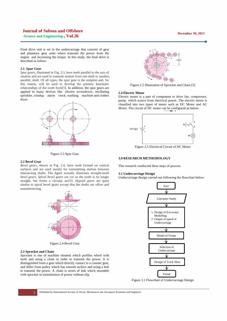
2.4 Electric Motor Electric motor is a part of component to drive fan, compressor, pump which source from electrical power. The electric motor is classified into two types of motor such as DC Motor and AC Motor. The circuit of DC motor can be configured as below:
Figure 2.5 Electrical Circuit of DC Motor
3.0 RESEARCH METHODOLOGY This research conducted three steps of process 3.1 Undercarriage Design Undercarriage design carried out following the flowchart below:
Start
Literature Study
1. Design of Excavator Modelling 2. Output of speed of Undercarriage
Model of Frame
Design of Track Shoe
Finish
Selection of Undercarriage
Figure 3.1 Flowchart of Undercarriage Design

Journal of Subsea and Offshore -Science and Engineering-, Vol.26
December 30, 2015
3 Published by International Society of Ocean, Mechanical and Aerospace Scientists and Engineers
The dimensions of the undercarriage were taken from 1:14 scaled model of the actual size so structured such that generates the layout as in Figure 3.2 below
Figure 3.2 Layout of Power Transmission of Undercarriage
Power transmission from driven motor to each track shoe using
a pair of bevel gear (gear 1 and gear 2) and two pairs of spur gears (pinion gears 3 to 6).
The layout made its CAD drawings into 3D models as shown in Figure 3.3 below
Figure 3.3 Result of 3D Design of Undercarriage
The transmission arrangement to obtain the undercarriage low
speed of 3.6 km/h and undercarriage hight speed 5.5 km/ as the speed of the excavator is generally where a motor driven rotation of 2000 rpm 3.2 Undercarriage Fabrication The process of making undercarriage conducted at the Laboratory of Production of Mechanical Engineering, University of Riau. Flow chart of the manufacturing process can be seen in Figure 3.5.
Making the frame by means of Steel box cut using grinding pieces with a length of 30 cm. Then one end of the steel box section is cut 10 cm with the aim to include idler and tension to set the track shoe and make the position of bearing needed to simplify and expedite the undercarriage in the running
Track shoe is made by cutting a plate that has a thickness of 2 mm and a length of 50 mm and a width of 15 mm. Plates that have been cut was installed in the cracks of the iron cylinder has been connected with the chain sprocket. Furthermore, the merger between the chain sprocket or the so-called track shoe with a steel box that has been cut. The result as in Fig. 3.5
Figure 3.5 Assembling of Track Shoe
Installation of the sprockets and gears. After completion of the
formation of the frame, the next step is the process of turning to make the position of the gear and then making a connection between the position of the gear to the frame (see in Fig. 3.6). The gears used are gears that are easy to obtain, is composed of two types of gears is a hypoid gear and spur gear and performed 3 times to get a final speed reducer such as undercarriage in general.
(a) The position of the gear (b) Sprocket and gear on the frame
Figure 3.6 Installation Stand Gear and Sprocket on Frame
Start
Fabrication of Track Shoe
Fabrication of Sprocket
Assembling
Finish
Fabrication of Frame
Figure 3.4 Flowchart of Fabrication

Journal of Subsea and Offshore -Science and Engineering-, Vol.26
December 30, 2015
4 Published by International Society of Ocean, Mechanical and Aerospace Scientists and Engineers
3.3 Undercarriage Testing At this stage we will perform an undercarriage testing activities. This process can be seen in Fig. 3.7 following a flow chart of the testing process.
This test was conducted to determine the outcome of designing and manufacturing has been done. Testing is done with three types of tests, among others: 1. Testing speed and a final round of undercarriage
This test was conducted to determine the speed and the final round of the excavator. Testing is done by giving the mileage on the excavator which was then measured how long it takes the excavator. And rotation speed testing is done with 3 variations of the track are: ceramics, asphalt and soil. While the rotation speed is obtained from then converted into angular velocity rounds finally obtained value.
2. Testing the direction of turn undercarriage This test is done to determine how much deflection angle that can be done by the excavator. Testing is also done with a variation of 3 tracks namely: ceramics, asphalt and soil (see in Fig. 3.8)
Figure 3.8 Testing Direction Turn
3. Tests on inclined plane.
This test is done to determine how much the maximum angle
that can be taken by the excavator. Testing was done with 6 variation of the angle that is 5o, 10o, 15o, 20o and 25o (see in Fig. 3.9)
Figure 3.9 Comparison Testing on inclined plane
4.0 RESULT AND DISCUSSION The testing had been conducted to obtained the data of speed and excavator’s manouver in several models of track like ceramic, asphalt and land. In Aspalth Track
0.198
0.2
0.202
0.204
0.206
0.208
0.21
0.212
0 0.2 0.4 0.6 0.8 1 1.2 1.4 1.6
Sp
ee
d (
m/s
)
Load (kg)
Asphalt
Figure 4.1 Load vs Speed in Asphalt Track
In the Figure 4.1 show the result of undercarriage experiment in the asphalt track, where the increasing of loads cause the speed of excavator decreased. Figure 4.2 illustrate the load vs rotation as well, the increasing of load affect to the rotation of undercarriage final drive.
76
77
78
79
80
81
0 0.2 0.4 0.6 0.8 1 1.2 1.4 1.6
Ro
tati
on
(rp
m)
Load (kg)
Asphalt
Figure 4.2 Load vs Rotation in Asphalt Track
Start
Testing
Results
Analysis
Finish
Conclusion
Figure 3.7 Flowchart of Undercarriage Testing

Journal of Subsea and Offshore -Science and Engineering-, Vol.26
December 30, 2015
5 Published by International Society of Ocean, Mechanical and Aerospace Scientists and Engineers
In Ceramic Track
0.238
0.24
0.242
0.244
0.246
0.248
0.25
0.252
0 0.2 0.4 0.6 0.8 1 1.2 1.4 1.6
Sp
ee
d (
m/
s)
Load (kg)
Ceramic
Figure 4.3 Load vs Speed in Ceramic Track
91
92
93
94
95
96
97
0 0.2 0.4 0.6 0.8 1 1.2 1.4 1.6
Ro
tati
on
(rp
m)
Load (kg)
Ceramic
Figure 4.4 Load vs Rotation In Ceramic Track
In the ceramic track as shown in figure 4.3 shows the speed of
excavator against the increasing of load, where the speed linearly decrease. The figure 4.4 shows the rotation of undercarriage decrease by increasing of load. In Unpaved Road
0.128
0.13
0.132
0.134
0.136
0.138
0.14
0.142
0 0.2 0.4 0.6 0.8 1 1.2 1.4 1.6
Sp
ee
d (
m/
s)
Load (kg)
Unpaved Road
Figure 4.5 Load vs Speed in Unpaved Road
49
50
51
52
53
54
0 0.2 0.4 0.6 0.8 1 1.2 1.4 1.6
Ro
tati
on
(rp
m)
Load (kg)
Unpaved Road
Figure 4.6 Load vs Rotation in Unpaved Road
In the figure 4.5 show the comparison between load and speed
in unpaved road. It indicates the speed of excavator on unpaved road track is the lowest speed when compare to other track, as well as the rotation of undercarriage final drive become decreasing by increasing of load. 5.0 CONCLUSION From the results of the design, manufacture and calculations have been performed, then obtained some conclusions of a thesis entitled designing and manufacturing excavator undercarriage components on the model in the Laboratory of Hydraulic and Pneumatic University of Riau, namely: 1. Provided the form of the undercarriage of the design and
manufacturing has been done with the long dimension of undercarriage 331 mm, width 234 mm and height 78.6 mm
2. From the test results that have been done so by doing three times the reduction of the gear system and using the motor power windows Toyota gained speed as the excavator excavator generally is 3.6 km / h or 1 m / s for low speed undercarriage and 5 , 5 km / h or 1.5 m / s for high speed undercarriage.
3. From the examination of the direction of turn can do the undercarriage on the track asphalt, ceramics and soil the minimum diameter are on the track of land with a diameter of 210 mm.
4. The maximum slope that can be achieved excavator which is 10 degrees with a power of 83.60 Watts.
5. Obtained a modified cable remote control to move the undercarriage..
REFERENCE 1. Julianto and Nazaruddin, 2004, Perencanaan dan Pengujian
Model Excavator, Kertas Karya Prodi D3 Teknik Mesin Universitas Riau.
2. Jati, Hidayah, 2011. Peningkatan Perawatan Komponen Undercarriage Alat Berat. Depok: Universitas Indonesia.
3. Prasetyo, Deta. 2010. Pembuatan Alat Praktikum Perawatan Sistem Transmisi Roda Gigi. Surakarta : Universitas Sebelas Maret
4. Soleh, Muhammad. 2005. Sistem Operasi dan Perawatan Travel Motor pada Excavator Hitachi Zaxis-200, Prodi D3 Teknik Mesin Universitas Riau.

Journal of Subsea and Offshore -Science and Engineering-, Vol.26
December 30, 2015
6 Published by International Society of Ocean, Mechanical and Aerospace Scientists and Engineers
5. Shigley, 2006, Mechanical Engineering Design 8th, McGraw-Hill Companies, USA