underground injection control program final permit: class ... · county of santa barbara laguna...
TRANSCRIPT

United States Environmental Protection Agency Underground Injection Control Program
FINAL PERMIT
Class I Nonhazardous Waste Injection Well Permit No. CA 10910004
Union Sugar No. 13 Santa Maria, California
Issued to:
County of Santa Barbara Laguna County Sanitation District
620 West Foster Road, Suite D Santa Maria, CA 93101

Table of Contents Part I. AUTHORIZATION TO INJECT .............................................................................. 5
Part II. SPECIFIC PERMIT CONDITIONS ......................................................................... 6
A. OPERATING REQUIREMENTS .............................................................................. 6 1. Financial Assurance ..................................................................................................... 6 2. Field Demonstration Submittal, Notification, and Reporting ............................ 6
B. WELL DETAILS............................................................................................................ 6 1. Location of Injection Well Union Sugar No. 13 .................................................... 6 2. Casing and Cementing ................................................................................................ 6 3. Tubing and Packer Specifications ............................................................................ 6 4. Injection Interval .......................................................................................................... 7 5. Confining Layer ........................................................................................................... 7 6. Monitoring Devices ..................................................................................................... 7 7. Proposed Changes and Workovers ........................................................................... 7 8. Workover and Plugging Procedures......................................................................... 8 9. Fall Off Pressure Test .................................................................................................. 8
C. CORRECTIVE ACTION ............................................................................................. 9 1. Annual ZEI Review ..................................................................................................... 9 2. Implementation of Corrective Actions .................................................................... 9
D. WELL OPERATION .................................................................................................... 9 1. Mechanical Integrity ................................................................................................... 9 2. Injection Formation: .................................................................................................. 12 3. Confining Layer: ........................................................................................................ 12 4. Injection Pressure Limitation .................................................................................. 12 5. Injection Rate Limitation.......................................................................................... 13 6. Injection Fluid Limitation ........................................................................................ 13
E. MONITORING, RECORDKEEPING, AND REPORTING OF RESULTS .... 13 1. Injection Well Monitoring Program ....................................................................... 13 2. Monitoring Information ........................................................................................... 14 3. Monitoring Devices ................................................................................................... 15 4. Recordkeeping ............................................................................................................ 16
Final Permit No. CA 10910004 Page 2 of 26

5. Reporting ..................................................................................................................... 17 F. PLUGGING AND ABANDONMENT................................................................... 19
1. Notice of Plugging and Abandonment .................................................................. 19 2. Plugging and Abandonment Plans......................................................................... 19 3. Cessation of Injection Activities ............................................................................. 19 4. Plugging and Abandonment Report ...................................................................... 19
G. FINANCIAL RESPONSIBILITY ............................................................................. 20 1. Demonstration of Financial Responsibility ......................................................... 20 2. Insolvency of Financial Institution ........................................................................ 20 3. Insolvency of Owner or Operator ........................................................................... 21
H. DURATION OF PERMIT ......................................................................................... 21
Part III. GENERAL PERMIT CONDITIONS ...................................................................... 22
A. EFFECT OF PERMIT ................................................................................................. 22 B. PERMIT ACTIONS.................................................................................................... 22
1. Modification, Revocation and Reissuance, or Termination .............................. 22 2. Transfers ...................................................................................................................... 22
C. SEVERABILITY .......................................................................................................... 23 D. CONFIDENTIALITY ................................................................................................. 23 E. GENERAL DUTIES AND REQUIREMENTS ...................................................... 23
1. Duty to Comply .......................................................................................................... 23 2. Penalties for Violations of Permit Conditions ..................................................... 23 3. Need to Halt or Reduce Activity Not a Defense .................................................. 23 4. Duty to Mitigate ......................................................................................................... 24 5. Proper Operation and Maintenance ....................................................................... 24 6. Property Rights ........................................................................................................... 24 7. Duty to Provide Information ................................................................................... 24 8. Inspection and Entry ................................................................................................. 24 9. Signatory Requirements ........................................................................................... 25 10. Additional Reporting ................................................................................................ 25 11. Continuation of Expiring Permit ............................................................................ 26
Final Permit No. CA 10910004 Page 3 of 26

APPENDIX A Project Location Map APPENDIX B Union Sugar No. 13 Injection Well As-Built Schematic APPENDIX C EPA Reporting Forms APPENDIX D Region 9 UIC Pressure Falloff Requirements APPENDIX E Region 9 Temperature Logging Requirements APPENDIX F Plugging and Abandonment Plan
Final Permit No. CA 10910004 Page 4 of 26

Part I. AUTHORIZATION TO INJECT
____________________________________
Pursuant to the Underground Injection Control regulations of the U.S. Environmental Protection Agency codified at Title 40 of the Code of Federal Regulations, Parts 124, 144, 145, 146, 147, and 148,
County of Santa Barbara Laguna County Sanitation District 620 West Foster Road Santa Maria, CA 93455
is hereby authorized, contingent upon meeting Permit conditions, to operate a Class I nonhazardous waste injection well facility with one (1) existing injection well, known as Union Sugar 13. Until this permit is made effective, Union Sugar 13 will continue to operate under the authority of the original permit CA 200000001. Union Sugar 13 is located in Section 14, Township 10N, Range 35W at the Laguna County Sanitation District Injection Well Facility in Santa Barbara County, California.
After meeting the requirements of Part II Section A.1 of this permit, injection is authorized to continue into the Monterey Formation for the purpose of disposal (from authorized sources) of non-hazardous brine derived from reverse osmosis treatment of wastewater. Operation of the well will be limited to maximum volume and pressure as stated in this permit.
All conditions set forth herein refer to Title 40 Parts 124, 144, 145, 146, 147, and 148 of the Code of Federal Regulations and are regulations that are in effect on the date that this permit is effective.
This final permit consists of twenty-six (26) pages plus appendices, and includes all items listed in the Table of Contents. Further, it is based upon representations made by the Permittee and on other information contained in the administrative record. It is the responsibility of the Permittee to read, understand, and comply with all terms and conditions of this permit.
This permit and the authorization to inject are issued for a period of ten years unless terminated under the conditions set forth in Part III, Section B.1. of this permit.
This permit is issued and effective on ______________________.
Alexis Strauss, Director Water Division, EPA Region 9
Final Permit No. CA 10910004 Page 5 of 26

Part II. SPECIFIC PERMIT CONDITIONS
A. OPERATING REQUIREMENTS
1. Financial Assurance The Permittee shall supply evidence of financial assurance prior to approval of the Final Permit, in accordance with Section G of this part.
2. Field Demonstration Submittal, Notification, and Reporting
a. Prior to any demonstration required in the following Sections B through D, the Permittee must submit plans for procedures and specifications to the U.S. Environmental Protection Agency Region IX Ground Water Office (EPA) for approval. The submittal address is provided in Section E, paragraph 5. No demonstration in these sections may proceed without prior written approval from EPA.
b. The Permittee must notify EPA at least thirty (30) days prior to performing any required field demonstrations after EPA approves the demonstration workplan, in order to allow EPA to arrange to witness if so elected.
c. The Permittee shall submit results of each demonstration required to EPA within sixty (60) days of completion.
California Division of Oil, Gas, and Geothermal Resources (DOGGR) reporting forms (such as a Well Summary Report) may be acceptable provided all information specified by this permit is included.
B. WELL DETAILS
1. Location of Injection Well Union Sugar No. 13 Injection well Union Sugar No. 13 authorized under this permit, is located at Section 14, Township 10, Range 35, SW in Santa Maria, California (See Appendix A).
2. Casing and Cementing The well schematic as-built details depicting casing and cement are incorporated into this permit as Appendix B.
3. Tubing and Packer Specifications The well schematic as-built details depicting the tubing and packer are incorporated into this permit as Appendix B.
Final Permit No. CA 10910004 Page 6 of 26

4. Injection Interval
5.
6.
7.
The injection zone is the Monterey Formation, a fractured shale, at an approximate depth of 4,800 feet to 5,336 feet below ground surface. The injection tubing is 3 ½ inch tubing with a 3 ½ packer set at a depth of approximately 4,780 feet inside the 5 ½ inch liner. The packer is set just above the Monterey shale. The well schematic as-built details depicting the injection interval, and tubing and packer details are incorporated into this permit as Appendix B.
Confining Layer The injection formation is confined by the Sisquoc Formation which is located at approximately 4,306 - 4,808 feet below ground surface.
Monitoring Devices The operator shall maintain in good operating condition:
a. A tap on the discharge line between the injection pump and the wellhead for the purpose of obtaining representative samples of injection fluid; and
b. Devices to measure and record injection pressure, annulus pressure, flow rate, and injection volumes, subject to the following:
(i) Pressure gauges shall be of a design to provide:
(1) A full pressure range of at least fifty (50) percent greater than the anticipated operating pressure; and
(2) A certified deviation accuracy of five (5) percent or less throughout the operating pressure range.
(ii) Flow meters shall measure cumulative volumes and be certified for a deviation accuracy of five (5) percent or less throughout the range of injection rates allowed by the permit.
Proposed Changes and Workovers The Permittee shall give advance notice to the Director of any planned physical alterations or additions to the permitted injection well. Any changes in the well construction will require prior approval of the EPA and a permit modification under the requirements of 40 CFR §144.39. In addition, the Permittee shall provide all records of well workovers, logging, or other subsequent test data, including required mechanical integrity testing, to EPA within sixty (60) days of completion of the activity. Appendix C refers to the appropriate reporting form (EPA Form 7520-12). Demonstration of mechanical integrity shall be performed
Final Permit No. CA 10910004 Page 7 of 26

within thirty (30) days of completion of workovers or alterations and prior to resuming injection activities, in accordance with Part II, Section D.1 (a).
8. Workover and Plugging Procedures Workover and plugging procedures must comply with the DOGGR "Onshore Well Regulations" of the California Code of Regulations, found in Title 14, Natural Resources, Division 2, Department of Conservation, Chapter 4, Article 3, Section 1722-1723. Drilling procedures shall also include the following:
a. Details for staging long-string cementing or justification for cementing without staging;
b. Records of daily Drilling Reports (electronic and hard copies);
c. Blowout Preventer (BOP) System testing on recorder charts including complete explanatory notes during the test(s),
d. Casing and other tubular and accessory measurement tallies; and
e. Details and justification for any open hole gravel packing.
Procedures provided on reporting forms such as DOGGR's Well Summary Report may be acceptable provided all required information as specified above is included.
9. Fall Off Pressure Test To monitor characteristics, a Fall off Pressure Test (FOT) shall be run in the injection well. The FOT must be conducted in accordance with EPA guidance found in Appendix D. Detailed plans for conducting the FOT must be submitted to EPA for review and approval. Once approved, the Permittee may schedule the FOT, providing EPA at least thirty (30) days notice before the test is conducted. The FOT shall be conducted in accordance with the following schedule:
a. An initial FOT shall be performed approximately six (6) months after the permit becomes effective, if a prior FOT has not been conducted within the last six (6) months under the prior permit.
b. Annually thereafter, the FOT test shall be repeated at an interval of not less than nine (9) months or greater than fifteen (15) months from the previous test. The results of the test shall be included with the quarterly report due each January, as described in Section E, paragraph 5 of this part.
Final Permit No. CA 10910004 Page 8 of 26

c. The latest static reservoir pressure and its cumulative behavior over time on a graphic plot of the injection zone shall be determined and reported with the FOT report listed above.
C. CORRECTIVE ACTION No corrective action for wells located within the Area of Review (AOR) is required pursuant to 40 CFR §144.55 and 40 CFR §146.7. All wells within the AOR have been plugged and abandoned in accordance with the requirements of the California Department of Oil, Gas and Geothermal Resources (DOGGR). There are no additional wells that have been added to the AOR as a result of the injection well operation, or the planned injection over the renewal period. Therefore, no corrective action is required at this time.
1. Annual ZEI Review Annually, the ZEI calculation shall be reviewed by the Permittee, based on any new data obtained from the FOT and static reservoir pressure tests required in Section B, paragraph 9 of this part. A copy of the modified ZEI calculations, along with all associated assumptions or justifications, shall be provided to EPA with the quarterly report due in January, as required in Section E, paragraph 5 of this part.
2. Implementation of Corrective Actions
a. If any wells requiring corrective action are found within the modified ZEI, a list of these wells along with their locations shall be provided to EPA as soon as possible.
b. If requested by EPA, the Permittee shall submit a plan to re-enter, plug, and abandon the wells listed in paragraph (a) above in such a manner to prevent the migration of fluids into a USDW.
c. The Permittee may not commence corrective action activities without prior written approval from EPA.
D. WELL OPERATION
1. Mechanical Integrity The Permittee shall demonstrate that the well has and maintains mechanical integrity consistent with 40 CFR § 148.8. The Permittee shall demonstrate that there are no significant leaks in the casing and tubing and that there is not significant fluid movement into or between USDWs though the casing wellbore annulus or vertical channels adjacent to the injection wellbore. The Permittee may not recommence injection after a workover which has compromised well integrity until it has received written notice from EPA that such a demonstration is satisfactory. The
Final Permit No. CA 10910004 Page 9 of 26

schedule for mechanical integrity testing is set forth in paragraph b, below.
a. Mechanical Integrity Tests (MITs)
Mechanical integrity testing shall conform to the following requirements throughout the life of the injection well:
i. Casing/tubing annular pressure (internal MIT) A demonstration of the absence of significant leaks in the casing, tubing and/or liner shall be made by performing a pressure test on the annular space between the tubing and long string casing. This test shall be for a minimum of thirty (30) minutes at a pressure equal to or greater than the maximum allowable injection pressure. A well passes the MIT if there is less than a five (5) percent change in pressure over the thirty (30) minute period. A pressure differential of at least 350 pounds per square inch (psi) between the tubing and annular pressures shall be maintained throughout the MIT.
ii. Continuous pressure monitoring The tubing/casing annulus pressure and injection pressure shall be monitored and recorded continuously by a digital instrument with a resolution of one tenth (0.1) psi. The average, maximum, and minimum monthly results shall be included in the quarterly report to EPA per Section E, paragraph 5 of this part unless more detailed records are requested by EPA.
iii. Injection profile survey (external MIT) In conjunction with the annual FOT required in Section B, paragraph 9(b), a demonstration that the injectate is confined to the proper zone shall be conducted and presented by the Permittee and subsequently approved by EPA. This demonstration shall consist of a radioactive tracer and a temperature log (as specified in Appendix E) or other diagnostic tool or procedure as approved by EPA. Detailed plans for conducting the external MIT must be submitted to EPA for review and approval. Once approved, the Permittee may schedule the external MIT, providing EPA at least thirty (30) days notice before the external MIT is conducted.
Final Permit No. CA 10910004 Page 10 of 26

iv. Cement Evaluation Analysis After casing is installed, after conducting a cement squeeze job in an open hole, or after any well cement repair, for any well constructed under this permit, the Permittee shall submit cementing records and cement evaluation logs that demonstrate the isolation of the injection interval and other formations from underground sources of drinking water by means of cementing the surface casing and the long string casing well bore annuli to surface. The analysis shall include a spherically-focused tool, run after the long-string casing is set and cemented, which enables the evaluation of the bond between cement and casing as well as of the bond between cement and formation. The Permittee may not commence or recommence injection until it has received written notice from EPA that such a demonstration is satisfactory.
b. Schedule for MITs EPA may require that an MIT be conducted at any time during the permitted life of the well. The Permittee shall also arrange and conduct MITs according to the following requirements:
i. Within thirty (30) days from completion of any workover where well integrity is compromised, or when any loss of mechanical integrity becomes evident during operation, an internal pressure MIT shall be conducted on each injection well authorized under this permit.
ii. At least annually for the life of the well, an injection profile survey external MIT shall be conducted on each injection well authorized under this permit in accordance with 40 CFR §146.8 and paragraph (a)(iii) above.
iii. At least once every five (5) years during the life of the well, an internal pressure MIT shall be conducted on each injection well authorized under this permit in accordance with 40 CFR §146.8 and paragraph (a)(i) above.
c. Loss of Mechanical Integrity The Permittee shall notify EPA, in accordance with Part III, Section E paragraph 10 of this permit, under any of the following circumstances:
Final Permit No. CA 10910004 Page 11 of 26

2.
3.
4.
i. The well fails to demonstrate mechanical integrity during a test, or
ii. A loss of mechanical integrity becomes evident during operation, or
iii. A significant change in the annulus or injection pressure occurs during normal operating conditions. See Section D.4 of this part.
Furthermore, in the event of (i), (ii), or (iii) above, injection activities shall be terminated immediately and operation shall not be resumed until the Permittee has taken necessary actions to restore mechanical integrity to the well and EPA gives approval to recommence injection.
d. Prohibition without Demonstration After the permit effective date, injection may continue only if:
i. The well has passed an internal pressure MIT in accordance with paragraph 1(a)(i) and 1(b) (iii) of this Section.
ii. The Permittee has received written notice from EPA that the internal pressure MIT demonstration is satisfactory.
Injection Formation: Injection shall be limited to the Monterey Formation at a depth of 4,800-5,336 feet.
Confining Layer: The injection formation is confined by the Sisquoc Formation which is located at a depth of approximately 4,306 - 4,808 feet.
Injection Pressure Limitation
a. Injection pressure measured at the wellhead shall not exceed 1,000 psig for injection into the Monterey Formation. In no case shall injection pressure initiate fractures above the injection interval.
b. The injection pressure limitations in paragraph (a) may be revised by the Director based on the results of a valid step-rate injection test in the proposed injection zone(s). The Director will determine any allowable pressure increase based upon the step-rate test results and other parameters reflecting actual injection operations.
Final Permit No. CA 10910004 Page 12 of 26

c. Any approval granted by the Director for increased injection pressure as stated in paragraph (b) above shall be made part of this permit by minor modification procedures (see 40 CFR §144.41).
5. Injection Rate Limitation
a. The injection rate shall not exceed 225,000 gallons per day at any time.
b. The Permittee may request an increase in the maximum rate allowed in paragraph (a). Any such request shall be made in writing to the Director.
c. Should any increase in rate be requested, the Permittee shall demonstrate to the satisfaction of the Director that the increase in volume will not interfere with the operation of the facility or' its ability to meet conditions described in the permit and would not change its classification, or cause migration of injectate or pressure buildup to occur beyond the AOR.
6. Injection Fluid Limitation
a. The Permittee shall not inject any hazardous wastes as defined by 40 CFR §261, at any time during the operation of the facility.
b. Injection fluids shall be limited to only waste fluids authorized by this permit, which include only brines developed from reverse osmosis treatment or water softener exchange treatment within LCSD. Brines from other sources or any other types of waste fluids from other sources are prohibited from injection well disposal at this Facility.
c. Additional authorized sources of brine from local water softener companies from the recharge of canister exchange water softening or water treatment units are: Rayne Water Company, Culligan of Santa Maria, Culligan of Lompoc and Golden State Water Company. Regular testing of brine from these sources is required as specified in Section E of this part.
E. MONITORING, RECORDKEEPING, AND REPORTING OF RESULTS
1. Injection Well Monitoring Program Injection fluids must be analyzed to yield representative data on their physical, chemical, or other relevant characteristics. The Permittee shall
Final Permit No. CA 10910004 Page 13 of 26
take samples at or before the wellhead for analysis. Test results shall be submitted to EPA on at least a quarterly basis (see paragraph 5 below).
Samples and measurements shall be representative of the monitored activity. The Permittee shall utilize applicable analytical methods described in Table I of 40 CFR §136.3 or in EPA Publication SW-846, "Test Methods for Evaluating Solid Waste, Physical/Chemical Methods," unless other methods have been approved by EPA.
a. Summary of acceptable analytic Methods:
i. Inorganic Constituents - appropriate USEPA methods for Major Anions and Cations (including an anion/cation balance).
ii. Solids - Standard Methods 2540C and 2540D for Total Dissolved Solids and Total Suspended Solids.
iii. General and Physical Parameters - appropriate USEPA methods for Temperature, Turbidity, pH, Conductivity, Hardness, Specific Gravity, Alkalinity, and Biological Oxygen Demand (BOD); and Density and Viscosity (See EPA Bulletin 712-C-96-032) under standard conditions.
b. Analysis of injection fluids. Quarterly, or whenever there is a significant change in injection fluids, sampling and analyses shall be performed as outlined in paragraph (a) above.
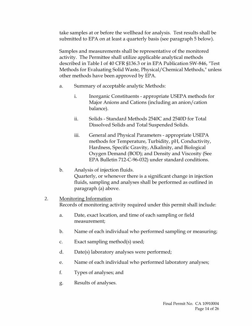
2. Monitoring Information Records of monitoring activity required under this permit shall include:
a. Date, exact location, and time of each sampling or field measurement;
b. Name of each individual who performed sampling or measuring;
c. Exact sampling method(s) used;
d. Date(s) laboratory analyses were performed;
e. Name of each individual who performed laboratory analyses;
f. Types of analyses; and
g. Results of analyses.
Final Permit No. CA 10910004 Page 14 of 26

3. Monitoring Devices
a. Continuous monitoring devices. Temperature, annular pressure, and injection pressure shall be measured at the wellhead using equipment of sufficient precision and accuracy. All measurements must be recorded at minimum to a resolution of one tenth of the unit of measure (e.g. injection rate and volume must be recorded to a resolution of a tenth of a gallon; pressure must be recorded to a resolution of a tenth of a psig; injection fluid temperature must be recorded to a resolution of a tenth of a degree Fahrenheit). Exact dates and times of measurements, when taken, must be recorded and submitted. Measurements are to be reported to EPA as described in paragraph 5 below. Injection rate shall be measured in the supply line immediately before the wellhead. The Permittee shall monitor the following parameters using the prescribed instruments and record the measurements at the prescribed frequency:
Monitoring Parameter Frequency Instrument
Injection rate (gallons per minute) a. Continuously b. Weekly
a. Chart Recorder b. Hand recorded
on Well Site Tally Sheet
Daily Injection Volume (gallons) Weekly Digital Totalizer – Hand recorded on
Well Site Tally Sheet
Total Cumulative Volume (gallons) Weekly Digital Totalizer – Hand recorded on
Well Site Tally Sheet
Well head injection pressure (psig) a. Continuously b. Weekly
a. Chart Recorder b. Hand recorded
on Well Site Tally Sheet
Annular pressure (psig) a. Continuously b. Weekly
a. Chart Recorder b. Hand recorded
on Well Site Tally Sheet
Injection fluid temperature (degrees Fahrenheit)
a. Continuously
b. Weekly
a. Chart Recorder b. Hand recorded
on Well Site Tally Sheet
Final Permit No. CA 10910004 Page 15 of 26

At such time as the injection pressure at the well head reaches an injection pressure of 50 psi, the Permittee is required to immediately notify EPA, and the Permittee shall modify the well monitoring equipment to accommodate electronic reporting of the injection data. The permit reporting requirements will be modified to reflect this change. EPA will also assess the need for additional testing to determine the maximum allowable surface injection pressure.
b. Calibration and Maintenance of Equipment All monitoring and recording equipment shall be calibrated and maintained on a regular basis to ensure proper working order of all equipment.
4. Recordkeeping The Permittee shall retain the following records and shall have them available at all times for examination by an EPA inspector in accordance with the following:
a. All monitoring information, including required observations, calibration and maintenance records, recordings for continuous monitoring instrumentation, copies of all reports required by this permit, and records of all data used to complete the permit application; and
b. Information on the nature and composition of all injected fluids; and
c. Results of the injectate "Hazardous Waste Determination" according to 40 CFR §262.11. Analytical results shall demonstrate that the injectate does not meet the definition of hazardous waste as defined in 40 CFR §261; and
d. Records and results of MITs, any other tests required by EPA, and any well workovers completed.
e. The Permittee shall maintain copies (or originals) of all records described in paragraphs (a) through (d) above during the operating life of the well and shall make such records available at all times for inspection at the facility.
f. The Permittee shall only discard the records described in paragraphs (a) through (d) if:
Final Permit No. CA 10910004 Page 16 of 26

i. the records are delivered to the Ground Water Office, or
ii. the Regional Administrator grants written approval to discard the records.
5. Reporting Quarterly, the Permittee shall submit accurate reports to EPA containing, at a minimum, the following information:
a. Continuously and weekly monitored values for the parameters specified for the injection well in paragraph 3(a) of this Section, above, as follows;
b. Monthly cumulative total volumes, as well as monthly average, minimum, and maximum values for the continuously monitored rate, pressure, and temperature parameters specified for the injection well in paragraph 3(a) of this Section, unless more detailed records are requested by EPA;
c. Quarterly analyses, to be included in the next quarterly report following completion:
i. Injection fluid characteristics for parameters specified in paragraph 1(a) of this Section;
ii. When appropriate, Injectate Hazardous Waste Determination according to paragraph 1(a) of this part.
d. To be included with the next quarterly report immediately following completion, results of any additional MITs or other tests required by EPA, and any well workovers completed.
e. To be included in the quarterly report due in January each year, the following annual analyses:
i. Annual reporting summary (EPA Form 7520-11);
ii. FOT results as required in Section B, paragraph 9 of this part;
Final Permit No. CA 10910004 Page 17 of 26

iii. Annual injection profile survey results as required in Section D; and
iv. Annual ZEI recalculation for each well as required in Section C.
f. To be included in the next quarterly report due in January after completion every five years, an internal MIT as required in Section D of this part.
g. A narrative description of all non-compliance that occurred during the reporting period.
Quarterly report forms as specified in Appendix C shall be submitted for the reporting periods by the respective due dates as listed below:
Reporting Period Report Due Jan, Feb, Mar Apr 28 Apr, May, June July 28 July, Aug, Sept Oct 28 Oct, Nov, Dec Jan 28
Monitoring results and all other reports required by this permit shall be submitted to the following address:
U.S. Environmental Protection Agency, Region IX Water Division Ground Water Office (Mail Code WTR-9) 75 Hawthorne St. San Francisco, CA 94105-3901
Copies of all reports shall also be provided to the following:
California Division of Oil, Gas, and Geothermal Resources District 6 Office Attn: Jim Carnahan 5075 S. Bradley Road, Suite 221 Santa Maria, CA 93455-5077
California Regional Water Quality Control Board Central Coast Section Attn: Sorrel Marks
Final Permit No. CA 10910004 Page 18 of 26

895 Aero Vista Place, Suite 101 San Luis Obispo, CA 93401
F. PLUGGING AND ABANDONMENT
1. Notice of Plugging and Abandonment The Permittee shall notify EPA no less than sixty (60) days before conversion, workover, or abandonment of any well authorized by this permit. EPA may require that the plugging and abandonment be witnessed by an EPA representative.
2. Plugging and Abandonment Plans The Permittee shall plug and abandon the well as provided in Appendix F, the general Plugging and Abandonment Program submitted as Attachment Q to the application, and consistent with DOGGR requirements and 40 CFR §146.10. EPA reserves the right to change the manner in which a well will be plugged if the well is modified during its permitted life or if the well is not consistent with EPA requirements for construction or mechanical integrity. EPA may require the Permittee to update the estimated plugging cost periodically. Such estimates shall be based upon costs which a third party would incur to plug the well, including mud and disposal costs, with appropriate contingencies.
3. Cessation of Injection Activities After a cessation of injection operations for two (2) years, the Permittee shall plug and abandon the inactive well(s) in accordance with the Plugging and Abandonment Plans, unless it:
a. Provides notice to EPA;
b. Has demonstrated that the well(s) will be used in the future; and
c. Has described actions or procedures, satisfactory to EPA that will be taken to ensure that the well will not endanger underground sources of drinking water during the period of temporary abandonment.
4. Plugging and Abandonment Report Within sixty (60) days after plugging any well, the Permittee shall submit a report on EPA Form 7520-14, to EPA. The report shall be certified as accurate by the person who performed the plugging operation, and shall consist of either:
Final Permit No. CA 10910004 Page 19 of 26

a. A statement that the well was plugged in accordance with the approved Plugging and Abandonment Plans, or
b. Where actual plugging differed from the Plugging and Abandonment Plans, a statement specifying the different procedures followed.
G. FINANCIAL RESPONSIBILITY
1. Demonstration of Financial Responsibility The Permittee is required to demonstrate and maintain financial responsibility and resources sufficient to close, plug, and abandon the underground injection operation as provided in the Plugging and Abandonment Plans and consistent with 40 CFR §144 Subpart D, which the Director has chosen to apply.
a. The Permittee shall maintain a bond rating within the four highest categories of Standard and Poor's (AAA, AA, A, or BBB), Moody's (Aaa, Aa, A, or Baa) or Fitch (AAA, AA, A, or BBB). If the most recent bond rating does not fall within the four highest categories, the Permitee shall post a financial instrument such as a surety bond with a standby trust agreement or arrange other financial assurance for the well constructed in the amount of $633,000 to guarantee closure.
b. The financial responsibility mechanism and amount shall be reviewed and updated periodically, upon request of EPA. The Permittee may be required to change to an alternate method of demonstrating financial responsibility. Any such change must be approved in writing by EPA prior to the change.
c. The Permitee must provide proof to EPA of its bond rating or renewal every year by March 31.
2. Insolvency of Financial Institution The Permittee must submit an alternate instrument of financial responsibility acceptable to EPA within sixty (60) days after either of the following events occurs:
a. The institution issuing the bond or financial instrument files for bankruptcy; or
Final Permit No. CA 10910004 Page 20 of 26

b. The authority of the trustee institution to act as trustee, or the authority of the institution issuing the financial instrument, is suspended or revoked.
Failure to submit an acceptable financial demonstration will result in the termination of this permit pursuant to 40 CFR §144.40(a)(1).
3. Insolvency of Owner or Operator An owner or operator must notify EPA by certified mail of the commencement of voluntary or involuntary proceedings under U.S. Code Title 11 (Bankruptcy), naming the owner or operator as debtor, within ten (10) business days. A guarantor of a corporate guarantee must make such a notification if he/she is named as debtor, as required under the terms of the guarantee.
H. DURATION OF PERMIT This permit and the authorization to inject are issued for a period of ten (10) years unless terminated under the conditions set forth in Part III, Section B.1 of this permit.
Final Permit No. CA 10910004 Page 21 of 26

Part III. GENERAL PERMIT CONDITIONS
A. EFFECT OF PERMIT The Permittee is allowed to engage in underground injection well operation in accordance with the conditions of this permit. The Permittee shall not construct, operate, maintain, convert, plug, abandon, or conduct any other injection activity in a manner that allows the movement of fluid containing any contaminant (as defined by 40 CFR §144.3) into underground sources of drinking water (as defined 40 CFR §§144.3, 146.3).
No injection fluids are allowed to migrate to any nearby oilfield production wells. Further, this permit requires systematic and predictive documentation over the facility's operational life to ensure that no injection fluids, either presently or in the future, will migrate to oilfield operation production wells.
Furthermore, any underground injection activity not specifically authorized in this permit is prohibited. The Permittee must comply with all applicable provisions of the Safe Drinking Water Act (SDWA) and 40 CFR Parts 124, 144, 145, 146, 147, and 148. Such compliance does not constitute a defense to any action brought under Section 1431 of the SDWA, 42 U.S.C. § 300(i), or any other common law, statute, or regulation other than Part C of the SDWA. Issuance of this permit does not convey property rights of any sort or any exclusive privilege; nor does it authorize any injury to persons or property, any invasion of other private rights, or any infringement of State or local law or regulations. Nothing in this permit shall be construed to relieve the Permittee of any duties under all applicable laws or regulations.
B. PERMIT ACTIONS
1. Modification, Revocation and Reissuance, or Termination EPA may, for cause or upon request from the Permittee, modify, revoke and reissue, or terminate this permit in accordance with 40 CFR §§124.5, 144.12, 144.39, and 144.40. The permit is also subject to minor modifications for cause as specified in 40 CFR §144.41. The filing of a request for a permit modification, revocation and reissuance, or termination, or a notification of planned changes or anticipated noncompliance by the Permittee, does not stay the applicability or enforceability of any permit condition. EPA may also modify, revoke and reissue, or terminate this permit in accordance with any amendments to the SDWA if the amendments have applicability to this permit.
2. Transfers This permit is not transferable to any person unless notice is first provided to EPA and the Permittee complies with requirements of 40 CFR §144.38. EPA may require modification or revocation and reissuance of the permit to change the name of the Permittee and incorporate such other requirements as may be necessary under the SDWA.
Final Permit No. CA 10910004 Page 22 of 26

C. SEVERABILITY The provisions of this permit are severable, and if any provision of this permit or the application of any provision of this permit to any circumstance is held invalid, the application of such provision to other circumstances and the remainder of this permit shall not be affected thereby.
D. CONFIDENTIALITY In accordance with 40 CFR §§2 and 144.5, any information submitted to EPA pursuant to this permit may be claimed as confidential by the submitter. Any such claim must be asserted at the time of submission by stamping the words "confidential business information" on each page containing such information. If no claim is made at the time of submission, EPA may make the information available to the public without further notice. If a claim is asserted, the validity of the claim will be assessed in accordance with the procedures contained in 40 CFR §2 (Public Information). Claims of confidentiality for the following information will be denied:
1. Name and address of the Permittee, or
2. Information dealing with the existence, absence, or level of contaminants in drinking water.
E. GENERAL DUTIES AND REQUIREMENTS
1. Duty to Comply The Permittee shall comply with all applicable Underground Injection Control (UIC) Program regulations and all conditions of this permit, except to the extent and for the duration such noncompliance is authorized by an emergency permit issued in accordance with 40 CFR §144.34. Any permit noncompliance constitutes a violation of the SDWA and is grounds for enforcement action; permit termination, revocation and reissuance, or modification; or denial of a permit renewal application. Such noncompliance may also be grounds for enforcement action under the Resource Conservation and Recovery Act (RCRA).
2. Penalties for Violations of Permit Conditions Any person who violates a permit requirement is subject to civil penalties, fines, and other enforcement action under the SDWA and may be subject to enforcement actions pursuant to RCRA. Any person who willfully violates a permit condition may be subject to criminal prosecution.
3. Need to Halt or Reduce Activity Not a Defense It shall not be a defense, for the Permittee in an enforcement action, that it would have been necessary to halt or reduce the permitted activity in order to maintain compliance with the conditions of this permit.
Final Permit No. CA 10910004 Page 23 of 26

4. Duty to Mitigate
5.
6.
7.
8.
The Permittee shall take all reasonable steps to minimize and correct any adverse impact on the environment resulting from noncompliance with this permit.
Proper Operation and Maintenance The Permittee shall at all times properly operate and maintain all facilities and systems of treatment and control (and related appurtenances) which are installed or used by the Permittee to achieve compliance with the conditions of this permit. Proper operation and maintenance includes effective performance, adequate funding, adequate operator staffing and training, and adequate laboratory and process controls, including appropriate quality assurance procedures. This provision requires the operation of back-up or auxiliary facilities or similar systems only when necessary to achieve compliance with the conditions of this permit.
Property Rights This permit does not convey any property rights of any sort, or any exclusive privilege.
Duty to Provide Information The Permittee shall furnish to EPA, within a time specified, any information which EPA may request to determine whether cause exists for modifying, revoking and reissuing, or terminating this permit, or to determine compliance with this permit. The Permittee shall also furnish to EPA, upon request, copies of records required to be kept by this permit.
Inspection and Entry The Permittee shall allow EPA, or an authorized representative, upon the presentation of credentials and other documents as may be required by law, to:
a. Enter upon the Permittee's premises where a regulated facility or activity is located or conducted, or where records are kept under the conditions of this permit;
b. Have access to and copy, at reasonable times, any records that are kept under the conditions of this permit;
c. Inspect and photograph at reasonable times any facilities, equipment (including monitoring and control equipment), practices, or operations regulated or required under this permit; and
Final Permit No. CA 10910004 Page 24 of 26

d. Sample or monitor at reasonable times, for the purposes of assuring permit compliance or as otherwise authorized by the SDWA, any substances or parameters at any location.
9. Signatory Requirements All applications, reports, or other information submitted to EPA shall be signed and certified by a responsible corporate officer or duly authorized representative according to 40 CFR §§122.22 and 144.32.
10. Additional Reporting
a. Planned Changes - The Permittee shall give notice to EPA as soon as possible of any planned physical alterations or additions to the permitted facility.
b. Anticipated Noncompliance - The Permittee shall give advance notice to EPA of any planned changes in the permitted facility or activity which may result in noncompliance with permit requirements.
c. Compliance Schedules - Reports of compliance or noncompliance with, or any progress reports on, interim and final requirements contained in any compliance schedule of this permit shall be submitted to EPA no later than thirty (30) days following each schedule date.
d. Twenty-four Hour Reporting
i. The Permittee shall report to EPA any noncompliance which may endanger health or the environment. Information shall be provided orally within twenty-four (24) hours from the time the Permittee becomes aware of the circumstances. The following information must be reported orally within twenty-four (24) hours:
A). Any monitoring or other information which indicates that any contaminant may cause an endangerment to an underground source of drinking water; and
B). Any noncompliance with a permit condition, or malfunction of the injection system, which may cause fluid migration into or between underground sources of drinking water; and
Final Permit No. CA 10910004 Page 25 of 26

ii. A written submission of all noncompliance as described in paragraph (b) shall also be provided to EPA within five (5) days of the time the Permittee becomes aware of the circumstances. The written submission shall contain a description of the noncompliance and its cause; the period of noncompliance, including exact dates and times; if the noncompliance has not been corrected, the anticipated time it is expected to continue; and steps taken or planned to reduce, eliminate, and prevent recurrence of the noncompliance.
e. Other Noncompliance At the time monitoring reports are submitted, the Permittee shall report in writing all other instances of noncompliance not otherwise reported. The Permittee shall submit the information listed in Part III, Section E.10 of this permit.
f. Other Information If the Permittee becomes aware that it failed to submit all relevant facts in the permit application, or submitted incorrect information in the permit application or in any report to EPA, the Permittee shall submit such facts or information within two (2) weeks of the time such facts or information becomes known.
11. Continuation of Expiring Permit
a. Duty to Reapply - If the Permittee wishes to continue an activity regulated by this permit after the expiration date of this permit, the Permittee must submit a complete application for a new permit at least one hundred and eighty (180) days before this permit expires.
b. Permit Extensions - The conditions and requirements of an expired permit continue in force and effect in accordance with 5 U.S.C. §558(c) until the effective date of a new permit, if:
i. The Permittee has submitted a timely and complete application for a new permit; and
ii. EPA, through no fault of the Permittee, does not issue a new permit with an effective date on or before the expiration date of the previous permit.
Final Permit No. CA 10910004 Page 26 of 26

98
-::;;====11 II II II \\
i I 2
• oi!
~ oil converted to waterflood
u p CJ
Legend
8 ~ oil-converted to water disposal-abandoned
;:f plugged and abandoned
0 other location
c::J 1 Mile (Area of lnvestigation AOI)
c::J 25 Mile Area of Rev iew (AOR)
\\ II
~ -0
,-)I-'
·• ..... _;:_\~ II II \\ II II II 11
132
II II II II \\ II
Area of Investigation Map
Project Manager: Greg Casey
Figure B-1 County of Santa Barbara, CA
Laguna Cmmty Sanitation District Dee Wellln·ection
012250 000 ~ 1,0001,2501,'5)01,7502,000
Feet
December 2009
Map Design: Jason Veale
9
10·
APPENDIX A - Project Location Map
Final Permit No. CA 10910004 Appendix A Page 1 of 1

A TT ACHlWENT M
Construction Details
fa Con•""'nfl
Figm-e M-1
Union Sugar No. 13 Wellbore Diagram
---- 1014", q1.SlbiftCasl.ngSet•t711' tttutnl.CdlOSW'face
14+-----7.0-,2,1 u,,11; H- I0Caslng Sctal5,050" andtcmcnt«lwi.th 6CX>sacks and squerzed cemmted Imm 2250' lo
apprn.wnately 2000' md lrnm Sudace dQ\\11 to the baSeof Uiesmiacecasmg.
SVt'. 17 lbift. N-80, HydriJ, 511 C.'lSing hum Smfaccro '1 ,801' and 4 W , 11.6
II-➔+---- lb/fr N-80, Vcnn,rn R1sh-J01nt Casing from •1.so1· Lo 51027' canmted in tY.l)
stises to sudate\\ith 250 sx o! Class G ccrnenr
■ ••• .... .,, .. ........ ,..t------·--··••11. ._ ..... . ••••rl'•a
5 Yi' Liner Hanger at 4 J 9l'
3W, 9.31bllt; K•55 h1blngset at'l,750' on a SmUh Ml••X p..irker
5 W , lotted liner from 5,029' to 5,l36'
Junkm hole from 5,lJO' to 5,3.l6'
TOIJIJ l)qXb 5,3.l6'
Octd,e,-2009
APPENDIX B - Union Sugar No. 13 Injection Well As-Built Well Schematic
(from Attachment M of the Permit Application)
Final Permit No. CA 10910004 Appendix B Page 1 of 1

APPENDIX C - EPA Reporting Forms
Form 7520-11: Annual Well Monitoring Report
Form 7520-12: Well Rework Report
Form 7520-14: Plugging and Abandonment Plan
Final Permit No. CA 10910004 Appendix C Page 1 of 1

APPENDIX D - Region 9 UIC Pressure Falloff Requirements
For reference please refer to: http://www.epa.gov/region09/water/groundwater/uic-docs/falloff-testing-guidlines.pdf
Final Permit No. CA 10910004 Appendix D Page 1 of 1

APPENDIX E - Region 9 Temperature Logging Requirements
A Temperature “Decay” Log (two separate temperature logging passes) must satisfy the following criteria to be considered a valid Mechanical Integrity Test (MIT) as specified by 40 CFR §146.8(c)(1). Variances to these requirements are expected for certain circumstances, but they must be approved prior to running the log. As a general rule, the well shall inject for approximately six (6) months prior to running a temperature decay progression sequence of logs.
1. With the printed log, also provide raw data for both logging runs (at least one data reading per foot depth) unless the logging truck is equipped with an analog panel as the processing device.
2. The heading on the log must be complete and include all the pertinent information, such as correct well name, location, elevations, etc.
3. The total shut-in times must be clearly shown in the heading. Minimum shut-in time for active injectors is twelve (12) hours for running the initial temperature log, followed by a second log, a minimum of four (4) hours later. These two log runs will be superimposed on the same track for final presentation.
4. The logging speed must be kept between twenty (20) and fifty (50) feet per minute (30 ft/min optimum) for both logs. The temperature sensor should be located as close to the bottom of the tool string as possible (logging downhole).
5. The vertical depth scale of the log should be one (1) or two (2) inches per one-hundred (100) feet to match lithology logs (see 7(b)). The horizontal temperature scale should be no more than one Fahrenheit degree per inch spacing.
6. The right hand tracks must contain the "absolute" temperature and the "differential" temperature curves with both log runs identified and clearly superimposed for comparison and interpretation purposes.
7. The left hand tracks must contain (unless impractical, but EPA must pre-approve any deviations):
(a) a collar locator log, (b) a lithology log which includes either:
(i) an historic Gamma Ray that is "readable", i.e. one that demonstrates lithologic changes without either excessive activity by the needle or severely dampened responses; or
(ii) a copy of an original spontaneous potential (SP) curve from either the subject well or from a representative, nearby well.
(c) A clear identification on the log showing the base of the lowermost Underground Source of Drinking Water (USDW(. A USDW is basically a formation that contains less than ten thousand (10,000) parts per million (ppm) Total Dissolved Solids (TDS) and is further defined in 40 CFR §144.3.
Final Permit No. CA 10910004 Appendix E Page 1 of 1

0MB No. 2040~1t42 Asiproval E.llpfr1t11 12/J1/2011
United St.rtas Envlronm1ntal Pro1ectlon Agency Waahlngton, DC 20460 ("' &EPA
PLUGGING AND ABANDONMENT PLAN
·1~:::;"::::-:1::~;~c~~r;··s~1i~~~i~; ni;tri~~· 3500 Black Road; Santa Maria, CA 93455 -----~- ····-··-------· --- ··------·-----··· ---
w
Locate Well and Outline Unit on Sectlon Plat - 840 Acras
N
' ' ' ' ' L....J._L.J._ ~.J.-L.J._ I I I I I I
'---t-i----t- '---t-i----t-~..l._L_l_ ~..l._L_L_
I I I I I I
~..l._L_l_ ~..l._l__[_ I I I I I I
'----t-i----t- '----t-i----t-~_l_L_l_ ~..l._L_l_
I I I I I I
E
Surface Loceuon DascrlJ)tlon
SW 114 of SW 1/4 of NW 1/4 of LJ114 of Section lii]Tovmshlpwi..1 Ran9e[i(J
Lo;ato ••II In two dlnctlons from nearest lines of quar1er sei:tlon and drllllng unit
Surface
Lo;atlon 1126 11. frrn (N/S) iS ·· ·1 Line of quarter aecllon
and ~ ft. frDl'!'I (EIW)~• of quarter eodlon.
TYPE OF AUTllORIZATION
0 fndlvldual Perml1
[]Aiaa Penni.
ORula
Number of WollsL-i
WELL ACTIVITY
IZ] CL.ASS I
□ CLAS811
0 Brine Dlapoeal
0 Enhanced Recovery
D Hydrocarbon Storage
[J CLASS Ill
s i --- J Woll Number [unionSu~No:_ lj_=~~--- [
CAS1NG AlfD TUBING RECORD AFTER PLUGGING
sacks of Cern■nt To Bo Used (each plug)
SlulT)' Volume To Be Pumped (cu. ft.]
Calculated Top of Plug (ft.}
MeHured Top of Plug jff tagged ft.: Slurry Wt. (l.b./Gal.J
METHOD OF EN.PLACEMENT OF CEMENT PLUGS
0 The Balance Method
D Tho Dump Baller Nethod
□ The Two-Plug Method
LJ Olhor
itlmated Cost lo Plu_a Wolls --·---
!
' . i
Certmcation I cor111'y under the penalty of law that I have p11l'!lonally examined and arn farnlllar wllh the Information ■ubmlttod In thla document and all attachments and that, bued on rny Inquiry of thoae lndlvldual, lminedlatoly reaponalblo for obtaining tho Information, I b■llovo U!al lhe lnrorm11tlon 111 true, ac,;:uri1to, and complete. I arn awaia that thera are tlgntrkant penalUos for aubmltUng false Information, Including U!e ponlblllty of fine and lmpr1aonment, (Rot. 40 CFR 144.32)
EPA Form 752<1-14 (Rev. 12-08}
!
APPENDIX F - Plugging and Abandonment Plan
Upon completion of injection activities the well shall be abandoned according to State and Federal regulations to ensure protection of Underground Sources of Drinking Water (from Attachment Q of the Permit Application).
Final Permit No. CA 10910004 Appendix F Page 1 of 4

ACHMENT Q
Plugging and Abandonment Plan
The pluggiI1g ,md ahmdoning procedure for the LCSD injection well is designed to be used
if the d.flm.'nt disposal well oper,1tious are abaudoned or if a well h,is re,u:hed the end of its
usefu1 life. Tiw pron,dure for well c1osurf' is described below and may hf' modified
accordi 113 Lo Llw dirf'dion of Llw EPA.
The LCSD shall notify the EPA of intent to plug at least 60 days p1ior to closure. The
following information will be provided:
• Type ,md numhPr ofplues
• Placement of each plug, including the elevation of both the top and bottom of the plug
• Type, grade, and quantity of the plugging material and additives to be used
• Method used to place plugs in hole
• Procedure usf'd to plue and ahandon the well
• Anv infmm.ttiou on ncvvlv constructed or discovered wells, or additional well d,1t,1,
within the AOR
Plugging and Abandonment Procedures
Plugging operations will be conducted as follows:
1. Record pressure decay in the injection zone for a time specified by the EPA.
2. Prepare location for workover rig.
3. Move workover rig onto location.
4. Rig up workover rig. Install BOPs.
5. Conduct annulus pressure test, temperature log and radioactive h'acer survey.
6. Remove wellhead and nipple up blow out preventers.
7. Kill well with brine.
8. Release packer. Pull out injection tubing sh"ing ,vith packer.
9. Conduct a casing inspection suTvey and a cement bond/e\Taluation log if more than fiye
years has passed since last cement log. The logs will be used to determine the plugging
procedures required to properly plug the injection well.
10. Run cement bridge plug with wire line or v.rork sh'ing; set retainer at 3,040 feet.
11. Run in hole with cement string to 3,040 feet.
12. Pump 13 barrels (540 feet) of 12.5 ppg cement on top of the bridge plug.
13. Pull tubing to 3,000 feet Reverse-circulate to clean tubing.
14. Wait for cement to dry for six hours.
15. l{un in hole with tubing to tag the first cement plug.
QI
Final Permit No. CA 10910004 Appendix F Page 2 of 4

Pull tuhin3 Lo 2,200 fppt_ Pump 40 harrels (1,700 rPeL) or 12.5 PP8 Cf'lllPnl.
l 7. Pu 11 tu hi 113 Lo 400 r PPL and revPrsP-ci rcu la LP to clean Lu hin3.
18. Wait for cPment to dry for six hours. Run in holP Lo ta3 cPment plu3.
19. Pull tu.hin3 to 50 fr.pt and pump 6 harrPls (40 fr.pt) of 12.5 ppr; cf'mf'nt.
20. Pull and lay down lubing.
21. Rig down and release rig.
22. Cut off casing 3 feet below ground surface and weld steel plate on top.
23. Inscribe on plate the injection well number, location, dates of use, total volume injected,
and uwner of well.
24. A permanent marker \Vill be erected at the well site. The marker will contain all
pertinent well information.
Figure Q-1 is a diagram of the well plugging plan. A plugging report will be filed with the
Executive Director withi.J.1 30 <lays after cmnpletion of plugging.
Post-Closure Plan
Upon closure of the injection wells, LCSD will submit a survey plat to the local zoning
authority that shall indicate the location of the injection wells relative to permanently
sunTeyed benchmarks. The facility will also submit a copy of the plat to the EPA and
provide information necessary to impose appropriate conditions on subsequent drilling
activities that may penetrate the well's confining or injection zone.
LCSD will retain records reflecting the nature, composition, and volume of all injected fluids
ford period of five ye.trs following plugging and .tb,m<lonment.
LCSD will place a monument or permanent marker to identify the plugged well prior to
abandonment. This marker will state the permit number, date of abandonment, and
company name.
02
Final Permit No. CA 10910004 Appendix F Page 3 of 4

ATTAOiMENr Q: PI.UGGING AND ABAI\IJONMENT Pl.AN
Figure Q-1
Union Sugar No. 13 Post Plugging Diagram
Cement Plug o. 3 ----1 .... 1-_.
Cement Plug No. 2
50 ~
---1--1--&.•500 ft
Bas e of freshwater at 2150 ft
C ement Plug No. I
;;:iill Cons ulting
2200 ft
4500 ft
Casing cut ofr 10ft from service.
10 ¾". 41.5 lb/ft C asing Set at 711' cemented to swface
i.i----- 7.0". 24 lb/ft . H ,40 Casing Set at 5,050' and cemented w ith 600 sacks and squeezed cemented from 2250 ' to approx imately 2000' :U1d from S wface down t o the base of the s urface casing.
5 ½", 17 lb/ft, N--80 , Hydril ,511 Casing from Surface t o 4,801' and 4 ½", 11.6 lb/ft N--80 .
.._ .......... _____ Ventura Flush-Joint Casing from 4,801' t o 5,027' cemented in t wo stages t o surface w ith 250 sx o f C lass G cement
5 ½" Liner Ha11 ger at 4,292'
4 ½". 11.6 lb/ft . '-80, from 4.SOJ ',5027'
Total Depth 5,336'
October 2009
Q-3
Final Permit No. CA 10910004 Appendix F Page 4 of 4