understanding soa security design and implementation
TRANSCRIPT

ibm.com/redbooks
UnderstandingSOA SecurityDesign and Implementation
Axel BueckerPaul Ashley
Martin BorrettMing Lu
Sridhar MuppidiNeil Readshaw
Introducing an SOA security reference architecture
Implementing scenarios based on the IBM SOA Foundation
Deploying SOA using IBM Tivoli security solutions
Front cover


Understanding SOA Security Design and Implementation
November 2007
International Technical Support Organization
SG24-7310-01

© Copyright International Business Machines Corporation 2007. All rights reserved.Note to U.S. Government Users Restricted Rights -- Use, duplication or disclosure restricted by GSA ADPSchedule Contract with IBM Corp.
Second Edition (November 2007)
This edition applies to Version 6.0 of IBM Tivoli Access Manager for e-business, Version 6.1.1 of IBM Tivoli Federated Identity Manager, and Version 6.0 of IBM Tivoli Directory Server. We are also discussing several other IBM software products in the context of hands-on scenarios.
Note: Before using this information and the product it supports, read the information in “Notices” on page xi.

Contents
Notices . . . . . . . . . . . . . . . . . . . . . . . . . . . . . . . . . . . . . . . . . . . . . . . . . . . . . . . xiTrademarks . . . . . . . . . . . . . . . . . . . . . . . . . . . . . . . . . . . . . . . . . . . . . . . . . . . xii
Preface . . . . . . . . . . . . . . . . . . . . . . . . . . . . . . . . . . . . . . . . . . . . . . . . . . . . . . xiiiThe team that wrote this IBM Redbook . . . . . . . . . . . . . . . . . . . . . . . . . . . . . . xiiiBecome a published author . . . . . . . . . . . . . . . . . . . . . . . . . . . . . . . . . . . . . . . xviComments welcome. . . . . . . . . . . . . . . . . . . . . . . . . . . . . . . . . . . . . . . . . . . . . xvi
Summary of changes . . . . . . . . . . . . . . . . . . . . . . . . . . . . . . . . . . . . . . . . . . xviiNovember 2007, Second Edition . . . . . . . . . . . . . . . . . . . . . . . . . . . . . . . . . . xvii
Part 1. Business context and foundation . . . . . . . . . . . . . . . . . . . . . . . . . . . . . . . . . . . . . . . . 1
Chapter 1. Business context . . . . . . . . . . . . . . . . . . . . . . . . . . . . . . . . . . . . . 31.1 Business scenarios . . . . . . . . . . . . . . . . . . . . . . . . . . . . . . . . . . . . . . . . . . . 4
1.1.1 Service creation at an insurance company . . . . . . . . . . . . . . . . . . . . . 41.1.2 Service connectivity at a government department . . . . . . . . . . . . . . . 51.1.3 Interaction and collaboration at a telecommunications company . . . . 5
1.2 Service orientation in SOA . . . . . . . . . . . . . . . . . . . . . . . . . . . . . . . . . . . . . 61.2.1 More than componentization. . . . . . . . . . . . . . . . . . . . . . . . . . . . . . . . 71.2.2 A focus on reuse . . . . . . . . . . . . . . . . . . . . . . . . . . . . . . . . . . . . . . . . . 9
1.3 Security considerations for SOA . . . . . . . . . . . . . . . . . . . . . . . . . . . . . . . . . 91.3.1 User and service identities and their propagation . . . . . . . . . . . . . . . 101.3.2 Connect to other organizations on a real-time, transactional basis . 111.3.3 Composite applications . . . . . . . . . . . . . . . . . . . . . . . . . . . . . . . . . . . 121.3.4 Managing security across diverse environments . . . . . . . . . . . . . . . 121.3.5 Protecting data . . . . . . . . . . . . . . . . . . . . . . . . . . . . . . . . . . . . . . . . . 131.3.6 Compliance with a growing set of regulations. . . . . . . . . . . . . . . . . . 13
1.4 Security in the service-oriented life cycle . . . . . . . . . . . . . . . . . . . . . . . . . 141.4.1 Security encompasses all aspects of the life cycle . . . . . . . . . . . . . . 14
1.5 Summary . . . . . . . . . . . . . . . . . . . . . . . . . . . . . . . . . . . . . . . . . . . . . . . . . . 16
Chapter 2. Architecture and technology foundation . . . . . . . . . . . . . . . . . 172.1 SOA security logical architecture . . . . . . . . . . . . . . . . . . . . . . . . . . . . . . . 18
2.1.1 Foundation scenarios . . . . . . . . . . . . . . . . . . . . . . . . . . . . . . . . . . . . 182.1.2 Logical deployment architecture . . . . . . . . . . . . . . . . . . . . . . . . . . . . 222.1.3 SOA security logical architecture . . . . . . . . . . . . . . . . . . . . . . . . . . . 33
2.2 Capabilities for a security reference model . . . . . . . . . . . . . . . . . . . . . . . . 352.2.1 Business Security Services. . . . . . . . . . . . . . . . . . . . . . . . . . . . . . . . 35
© Copyright IBM Corp. 2007. All rights reserved. iii

2.2.2 Information Technology (IT) Security Services . . . . . . . . . . . . . . . . . 412.2.3 Security Enablers . . . . . . . . . . . . . . . . . . . . . . . . . . . . . . . . . . . . . . . 472.2.4 Policy Management. . . . . . . . . . . . . . . . . . . . . . . . . . . . . . . . . . . . . . 492.2.5 Governance and Risk Management . . . . . . . . . . . . . . . . . . . . . . . . . 56
2.3 IBM SOA Security Reference Model . . . . . . . . . . . . . . . . . . . . . . . . . . . . . 562.4 Architecture decision guide . . . . . . . . . . . . . . . . . . . . . . . . . . . . . . . . . . . . 592.5 IBM products and services . . . . . . . . . . . . . . . . . . . . . . . . . . . . . . . . . . . . 622.6 Summary . . . . . . . . . . . . . . . . . . . . . . . . . . . . . . . . . . . . . . . . . . . . . . . . . . 63
Part 2. IBM SOA Foundation scenarios . . . . . . . . . . . . . . . . . . . . . . . . . . . . . . . . . . . . . . . . 65
Chapter 3. IBM SOA Foundation Service Creation scenario. . . . . . . . . . . 673.1 Scenario overview . . . . . . . . . . . . . . . . . . . . . . . . . . . . . . . . . . . . . . . . . . . 68
3.1.1 Direct exposure architectural pattern . . . . . . . . . . . . . . . . . . . . . . . . 683.1.2 Indirect exposure architectural pattern . . . . . . . . . . . . . . . . . . . . . . . 703.1.3 Security requirements . . . . . . . . . . . . . . . . . . . . . . . . . . . . . . . . . . . . 70
3.2 Applying the IBM SOA Security Reference Model . . . . . . . . . . . . . . . . . . 723.2.1 Business Security Services. . . . . . . . . . . . . . . . . . . . . . . . . . . . . . . . 723.2.2 IT Security Services . . . . . . . . . . . . . . . . . . . . . . . . . . . . . . . . . . . . . 743.2.3 Security Enablers . . . . . . . . . . . . . . . . . . . . . . . . . . . . . . . . . . . . . . . 843.2.4 Security Policy Management. . . . . . . . . . . . . . . . . . . . . . . . . . . . . . . 843.2.5 Governance and Risk Management . . . . . . . . . . . . . . . . . . . . . . . . . 863.2.6 Summary. . . . . . . . . . . . . . . . . . . . . . . . . . . . . . . . . . . . . . . . . . . . . . 86
Chapter 4. IBM SOA Foundation Service Connectivity scenario . . . . . . . 874.1 Scenario overview . . . . . . . . . . . . . . . . . . . . . . . . . . . . . . . . . . . . . . . . . . . 88
4.1.1 Security requirements . . . . . . . . . . . . . . . . . . . . . . . . . . . . . . . . . . . . 904.2 Applying the IBM SOA Security Reference Model . . . . . . . . . . . . . . . . . . 91
4.2.1 Business Security Services. . . . . . . . . . . . . . . . . . . . . . . . . . . . . . . . 914.2.2 IT Security Services . . . . . . . . . . . . . . . . . . . . . . . . . . . . . . . . . . . . . 924.2.3 Security Enablers . . . . . . . . . . . . . . . . . . . . . . . . . . . . . . . . . . . . . . . 984.2.4 Security Policy Management. . . . . . . . . . . . . . . . . . . . . . . . . . . . . . . 994.2.5 Governance and Risk Management . . . . . . . . . . . . . . . . . . . . . . . . . 99
4.3 Summary . . . . . . . . . . . . . . . . . . . . . . . . . . . . . . . . . . . . . . . . . . . . . . . . . . 99
Chapter 5. IBM SOA Foundation Interaction and Collaboration Services scenario . . . . . . . . . . . . . . . . . . . . . . . . . . . . . . . . . . . . . . . . . . . 101
5.1 Scenario overview . . . . . . . . . . . . . . . . . . . . . . . . . . . . . . . . . . . . . . . . . . 1025.1.1 Overview of the Interaction and Collaboration Services scenario . . 1025.1.2 Web single sign-on perspective . . . . . . . . . . . . . . . . . . . . . . . . . . . 1035.1.3 Web services perspective . . . . . . . . . . . . . . . . . . . . . . . . . . . . . . . . 1055.1.4 Security requirements . . . . . . . . . . . . . . . . . . . . . . . . . . . . . . . . . . . 106
5.2 Applying the IBM SOA Security Reference Model . . . . . . . . . . . . . . . . . 1075.2.1 Business Security Services. . . . . . . . . . . . . . . . . . . . . . . . . . . . . . . 107
iv Understanding SOA Security Design and Implementation

5.2.2 IT Security Services . . . . . . . . . . . . . . . . . . . . . . . . . . . . . . . . . . . . 1115.2.3 Security Enablers . . . . . . . . . . . . . . . . . . . . . . . . . . . . . . . . . . . . . . 1235.2.4 Security Policy Management. . . . . . . . . . . . . . . . . . . . . . . . . . . . . . 1235.2.5 Governance and Risk Management . . . . . . . . . . . . . . . . . . . . . . . . 124
5.3 Summary . . . . . . . . . . . . . . . . . . . . . . . . . . . . . . . . . . . . . . . . . . . . . . . . . 124
Chapter 6. IBM SOA Foundation Business Process Management scenario . . . . . . . . . . . . . . . . . . . . . . . . . . . . . . . . . . . . . . . . . . . 125
6.1 Scenario overview . . . . . . . . . . . . . . . . . . . . . . . . . . . . . . . . . . . . . . . . . . 1266.1.1 Business Process Management architectural pattern. . . . . . . . . . . 1286.1.2 Service Component Architecture (SCA) . . . . . . . . . . . . . . . . . . . . . 1296.1.3 Security requirements . . . . . . . . . . . . . . . . . . . . . . . . . . . . . . . . . . . 130
6.2 Applying the IBM SOA Security Reference Model . . . . . . . . . . . . . . . . . 1326.2.1 Business Security Services. . . . . . . . . . . . . . . . . . . . . . . . . . . . . . . 1326.2.2 IT Security Services . . . . . . . . . . . . . . . . . . . . . . . . . . . . . . . . . . . . 1336.2.3 Security Enablers . . . . . . . . . . . . . . . . . . . . . . . . . . . . . . . . . . . . . . 1426.2.4 Security Policy Management. . . . . . . . . . . . . . . . . . . . . . . . . . . . . . 1436.2.5 Governance and Risk Management . . . . . . . . . . . . . . . . . . . . . . . . 143
6.3 Summary . . . . . . . . . . . . . . . . . . . . . . . . . . . . . . . . . . . . . . . . . . . . . . . . . 144
Part 3. Securing the Service Creation scenario . . . . . . . . . . . . . . . . . . . . . . . . . . . . . . . . . 145
Chapter 7. Business scenario . . . . . . . . . . . . . . . . . . . . . . . . . . . . . . . . . . 1477.1 Business model . . . . . . . . . . . . . . . . . . . . . . . . . . . . . . . . . . . . . . . . . . . . 148
7.1.1 Overview . . . . . . . . . . . . . . . . . . . . . . . . . . . . . . . . . . . . . . . . . . . . . 1487.1.2 Initial context - ITSOTelco. . . . . . . . . . . . . . . . . . . . . . . . . . . . . . . . 1497.1.3 Initial context - ITSOBank . . . . . . . . . . . . . . . . . . . . . . . . . . . . . . . . 1497.1.4 Preliminary SOA engagement. . . . . . . . . . . . . . . . . . . . . . . . . . . . . 1507.1.5 Business logic . . . . . . . . . . . . . . . . . . . . . . . . . . . . . . . . . . . . . . . . . 1517.1.6 Authentication and authorization. . . . . . . . . . . . . . . . . . . . . . . . . . . 152
7.2 Business requirements . . . . . . . . . . . . . . . . . . . . . . . . . . . . . . . . . . . . . . 1537.3 Security requirements . . . . . . . . . . . . . . . . . . . . . . . . . . . . . . . . . . . . . . . 1537.4 Summary . . . . . . . . . . . . . . . . . . . . . . . . . . . . . . . . . . . . . . . . . . . . . . . . . 155
Chapter 8. Solution design . . . . . . . . . . . . . . . . . . . . . . . . . . . . . . . . . . . . . 1578.1 Solution overview . . . . . . . . . . . . . . . . . . . . . . . . . . . . . . . . . . . . . . . . . . 1588.2 Business Security Services . . . . . . . . . . . . . . . . . . . . . . . . . . . . . . . . . . . 159
8.2.1 Compliance and Reporting . . . . . . . . . . . . . . . . . . . . . . . . . . . . . . . 1608.2.2 Data Protection, Privacy, and Disclosure Control . . . . . . . . . . . . . . 1608.2.3 Non-repudiation Services . . . . . . . . . . . . . . . . . . . . . . . . . . . . . . . . 1608.2.4 Identity and Access . . . . . . . . . . . . . . . . . . . . . . . . . . . . . . . . . . . . . 1608.2.5 Trust Management . . . . . . . . . . . . . . . . . . . . . . . . . . . . . . . . . . . . . 1608.2.6 Secure Systems and Networks . . . . . . . . . . . . . . . . . . . . . . . . . . . . 161
8.3 IT Security Services . . . . . . . . . . . . . . . . . . . . . . . . . . . . . . . . . . . . . . . . 162
Contents v
8.3.1 Identity Services . . . . . . . . . . . . . . . . . . . . . . . . . . . . . . . . . . . . . . . 1628.3.2 Authentication Services. . . . . . . . . . . . . . . . . . . . . . . . . . . . . . . . . . 1658.3.3 Authorization Services . . . . . . . . . . . . . . . . . . . . . . . . . . . . . . . . . . 1688.3.4 Confidentiality Services. . . . . . . . . . . . . . . . . . . . . . . . . . . . . . . . . . 1708.3.5 Integrity Services. . . . . . . . . . . . . . . . . . . . . . . . . . . . . . . . . . . . . . . 1718.3.6 Audit Services . . . . . . . . . . . . . . . . . . . . . . . . . . . . . . . . . . . . . . . . . 173
8.4 Security Enablers . . . . . . . . . . . . . . . . . . . . . . . . . . . . . . . . . . . . . . . . . . 1758.5 Security policy management . . . . . . . . . . . . . . . . . . . . . . . . . . . . . . . . . . 176
8.5.1 Policy administration . . . . . . . . . . . . . . . . . . . . . . . . . . . . . . . . . . . . 1768.5.2 Policy distribution and transformation . . . . . . . . . . . . . . . . . . . . . . . 1778.5.3 Policy decision and enforcement . . . . . . . . . . . . . . . . . . . . . . . . . . 1778.5.4 Monitoring and reporting . . . . . . . . . . . . . . . . . . . . . . . . . . . . . . . . . 178
8.6 Governance and Risk Management . . . . . . . . . . . . . . . . . . . . . . . . . . . . 1798.7 Summary . . . . . . . . . . . . . . . . . . . . . . . . . . . . . . . . . . . . . . . . . . . . . . . . . 179
Chapter 9. Technical implementation . . . . . . . . . . . . . . . . . . . . . . . . . . . . 1819.1 Implementation scope . . . . . . . . . . . . . . . . . . . . . . . . . . . . . . . . . . . . . . . 1829.2 Key stores . . . . . . . . . . . . . . . . . . . . . . . . . . . . . . . . . . . . . . . . . . . . . . . . 182
9.2.1 Keys . . . . . . . . . . . . . . . . . . . . . . . . . . . . . . . . . . . . . . . . . . . . . . . . 1829.2.2 Key stores . . . . . . . . . . . . . . . . . . . . . . . . . . . . . . . . . . . . . . . . . . . . 183
9.3 Add Web services security to the ITSOTelco Portal application . . . . . . . 1849.3.1 Configure request generator . . . . . . . . . . . . . . . . . . . . . . . . . . . . . . 1859.3.2 Configure response consumer . . . . . . . . . . . . . . . . . . . . . . . . . . . . 193
9.4 Deploy ITSOTelco Portal application . . . . . . . . . . . . . . . . . . . . . . . . . . . 2009.4.1 Infrastructure configuration . . . . . . . . . . . . . . . . . . . . . . . . . . . . . . . 2019.4.2 Install ITSOTelco Portal application . . . . . . . . . . . . . . . . . . . . . . . . 2019.4.3 Configure ITSOTelco Portal application . . . . . . . . . . . . . . . . . . . . . 202
9.5 Configure Federated Identity Manager for ITSOTelco . . . . . . . . . . . . . . 2039.6 Configure XML firewall . . . . . . . . . . . . . . . . . . . . . . . . . . . . . . . . . . . . . . 210
9.6.1 Infrastructure configuration . . . . . . . . . . . . . . . . . . . . . . . . . . . . . . . 2109.6.2 Add XML firewall . . . . . . . . . . . . . . . . . . . . . . . . . . . . . . . . . . . . . . . 210
9.7 Add Web services security to the ITSOBanker2007 application . . . . . . . 2379.7.1 Configure request consumer. . . . . . . . . . . . . . . . . . . . . . . . . . . . . . 2389.7.2 Configure response generator . . . . . . . . . . . . . . . . . . . . . . . . . . . . 247
9.8 Deploy ITSOBanker2007 application . . . . . . . . . . . . . . . . . . . . . . . . . . . 2539.8.1 Infrastructure configuration . . . . . . . . . . . . . . . . . . . . . . . . . . . . . . . 2549.8.2 Installing the CICS ECI resource adapter . . . . . . . . . . . . . . . . . . . . 2549.8.3 Configuring the CICS Connection Factory . . . . . . . . . . . . . . . . . . . 2569.8.4 Configure a JAAS login module . . . . . . . . . . . . . . . . . . . . . . . . . . . 2609.8.5 Install the ITSOBanker2007 application . . . . . . . . . . . . . . . . . . . . . 263
9.9 Configure Federated Identity Manager for ITSOBank. . . . . . . . . . . . . . . 2659.9.1 Identity mediation for XML firewall . . . . . . . . . . . . . . . . . . . . . . . . . 2669.9.2 Identity mediation for ITSOBanker2007 application . . . . . . . . . . . . 272
vi Understanding SOA Security Design and Implementation

9.9.3 Deploy LDAP mapping module . . . . . . . . . . . . . . . . . . . . . . . . . . . . 2789.9.4 Create LDAP mapping module instance . . . . . . . . . . . . . . . . . . . . . 2809.9.5 Create RACF passticket module instance . . . . . . . . . . . . . . . . . . . 2819.9.6 Create Username token module instance. . . . . . . . . . . . . . . . . . . . 2839.9.7 Identity mediation for CICS connectivity . . . . . . . . . . . . . . . . . . . . . 2849.9.8 Restart WebSphere Application Server . . . . . . . . . . . . . . . . . . . . . 288
9.10 Testing the solution . . . . . . . . . . . . . . . . . . . . . . . . . . . . . . . . . . . . . . . . 2889.10.1 Create the test user. . . . . . . . . . . . . . . . . . . . . . . . . . . . . . . . . . . . 2899.10.2 Access the application . . . . . . . . . . . . . . . . . . . . . . . . . . . . . . . . . 2909.10.3 Message traces. . . . . . . . . . . . . . . . . . . . . . . . . . . . . . . . . . . . . . . 2919.10.4 Interaction with the Federated Identity Manager STS. . . . . . . . . . 296
9.11 Summary . . . . . . . . . . . . . . . . . . . . . . . . . . . . . . . . . . . . . . . . . . . . . . . . 303
Part 4. Securing the Service Connectivity scenario . . . . . . . . . . . . . . . . . . . . . . . . . . . . . 305
Chapter 10. Business scenario . . . . . . . . . . . . . . . . . . . . . . . . . . . . . . . . . 30710.1 Business context . . . . . . . . . . . . . . . . . . . . . . . . . . . . . . . . . . . . . . . . . . 308
10.1.1 Business problem . . . . . . . . . . . . . . . . . . . . . . . . . . . . . . . . . . . . . 30810.1.2 Project charter. . . . . . . . . . . . . . . . . . . . . . . . . . . . . . . . . . . . . . . . 308
10.2 IT context. . . . . . . . . . . . . . . . . . . . . . . . . . . . . . . . . . . . . . . . . . . . . . . . 30910.2.1 LargeCo . . . . . . . . . . . . . . . . . . . . . . . . . . . . . . . . . . . . . . . . . . . . 30910.2.2 SmallCo. . . . . . . . . . . . . . . . . . . . . . . . . . . . . . . . . . . . . . . . . . . . . 310
10.3 Summary . . . . . . . . . . . . . . . . . . . . . . . . . . . . . . . . . . . . . . . . . . . . . . . . 311
Chapter 11. Solution design . . . . . . . . . . . . . . . . . . . . . . . . . . . . . . . . . . . . 31311.1 Solution overview . . . . . . . . . . . . . . . . . . . . . . . . . . . . . . . . . . . . . . . . . 31411.2 Business Security Services . . . . . . . . . . . . . . . . . . . . . . . . . . . . . . . . . . 315
11.2.1 Compliance and Reporting . . . . . . . . . . . . . . . . . . . . . . . . . . . . . . 31511.2.2 Data Protection, Privacy, and Disclosure Control . . . . . . . . . . . . . 31611.2.3 Non-repudiation Services . . . . . . . . . . . . . . . . . . . . . . . . . . . . . . . 31611.2.4 Identity and Access . . . . . . . . . . . . . . . . . . . . . . . . . . . . . . . . . . . . 31611.2.5 Trust Management . . . . . . . . . . . . . . . . . . . . . . . . . . . . . . . . . . . . 31711.2.6 Secure Systems and Networks . . . . . . . . . . . . . . . . . . . . . . . . . . . 317
11.3 IT Security Services . . . . . . . . . . . . . . . . . . . . . . . . . . . . . . . . . . . . . . . 31811.3.1 Identity Services . . . . . . . . . . . . . . . . . . . . . . . . . . . . . . . . . . . . . . 31811.3.2 Authentication Services. . . . . . . . . . . . . . . . . . . . . . . . . . . . . . . . . 32111.3.3 Authorization Services . . . . . . . . . . . . . . . . . . . . . . . . . . . . . . . . . 32411.3.4 Confidentiality Services. . . . . . . . . . . . . . . . . . . . . . . . . . . . . . . . . 32511.3.5 Integrity Services. . . . . . . . . . . . . . . . . . . . . . . . . . . . . . . . . . . . . . 32611.3.6 Audit Services . . . . . . . . . . . . . . . . . . . . . . . . . . . . . . . . . . . . . . . . 326
11.4 Security Enablers . . . . . . . . . . . . . . . . . . . . . . . . . . . . . . . . . . . . . . . . . 32811.5 Security Policy Management. . . . . . . . . . . . . . . . . . . . . . . . . . . . . . . . . 329
11.5.1 Policy Administration. . . . . . . . . . . . . . . . . . . . . . . . . . . . . . . . . . . 32911.5.2 Policy Distribution and Transformation . . . . . . . . . . . . . . . . . . . . . 330
Contents vii

11.5.3 Policy Decision and Enforcement . . . . . . . . . . . . . . . . . . . . . . . . . 33011.5.4 Monitoring and Reporting . . . . . . . . . . . . . . . . . . . . . . . . . . . . . . . 331
11.6 Governance and Risk Management . . . . . . . . . . . . . . . . . . . . . . . . . . . 33111.7 Summary . . . . . . . . . . . . . . . . . . . . . . . . . . . . . . . . . . . . . . . . . . . . . . . . 331
Chapter 12. Technical implementation . . . . . . . . . . . . . . . . . . . . . . . . . . . 33312.1 Implementation scope . . . . . . . . . . . . . . . . . . . . . . . . . . . . . . . . . . . . . . 33412.2 Adding the token exchange mediation primitive using WebSphere
Integration Developer . . . . . . . . . . . . . . . . . . . . . . . . . . . . . . . . . . . . . . . 33412.2.1 Adding the token exchange mediation primitive . . . . . . . . . . . . . . 33512.2.2 Deploying the new mediation . . . . . . . . . . . . . . . . . . . . . . . . . . . . 346
12.3 Configuring identity propagation by modifying the LargeCo and SmallCo applications. . . . . . . . . . . . . . . . . . . . . . . . . . . . . . . . . . . . . . . . . . . . . . . 346
12.3.1 Configuring request generator in LargeCo portlet . . . . . . . . . . . . . 34712.3.2 Configuring the request consumer in SmallCo Web service. . . . . 352
12.4 Deploying the LargeCo and SmallCo applications . . . . . . . . . . . . . . . . 36012.4.1 Infrastructure configuration . . . . . . . . . . . . . . . . . . . . . . . . . . . . . . 36012.4.2 Deploy LargeWESBPortlet . . . . . . . . . . . . . . . . . . . . . . . . . . . . . . 36012.4.3 Deploy SmallWSTooWeb application . . . . . . . . . . . . . . . . . . . . . . 362
12.5 Configure Federated Identity Manager trust chains . . . . . . . . . . . . . . . 36212.5.1 Identity mediation for LargeCo portlet . . . . . . . . . . . . . . . . . . . . . . 36312.5.2 Identity mediation for LargeCo ESB . . . . . . . . . . . . . . . . . . . . . . . 369
12.6 Testing the solution . . . . . . . . . . . . . . . . . . . . . . . . . . . . . . . . . . . . . . . . 37412.6.1 Creating test accounts . . . . . . . . . . . . . . . . . . . . . . . . . . . . . . . . . 37512.6.2 Accessing the service via the portal . . . . . . . . . . . . . . . . . . . . . . . 37612.6.3 Federated Identity Manager Security Token Service interaction . 37712.6.4 Examine WebSphere ESB message logs. . . . . . . . . . . . . . . . . . . 386
12.7 Summary . . . . . . . . . . . . . . . . . . . . . . . . . . . . . . . . . . . . . . . . . . . . . . . . 392
Appendix A. Introduction to service-oriented architecture. . . . . . . . . . . 393Service-oriented architecture overview . . . . . . . . . . . . . . . . . . . . . . . . . . . . . 394
Definition of a service-oriented architecture . . . . . . . . . . . . . . . . . . . . . . . 394IBM SOA Reference Model: Challenges and drivers for SOA . . . . . . . . . . . . 396
Why SOA now. . . . . . . . . . . . . . . . . . . . . . . . . . . . . . . . . . . . . . . . . . . . . . 400SOA approach for building a solution . . . . . . . . . . . . . . . . . . . . . . . . . . . . 403
Getting started with SOA . . . . . . . . . . . . . . . . . . . . . . . . . . . . . . . . . . . . . . . . 405SOA adoption . . . . . . . . . . . . . . . . . . . . . . . . . . . . . . . . . . . . . . . . . . . . . . 405IBM SOA entry points . . . . . . . . . . . . . . . . . . . . . . . . . . . . . . . . . . . . . . . . 406IBM SOA Foundation . . . . . . . . . . . . . . . . . . . . . . . . . . . . . . . . . . . . . . . . 408
Web services and SOA . . . . . . . . . . . . . . . . . . . . . . . . . . . . . . . . . . . . . . . . . 408Web services technologies . . . . . . . . . . . . . . . . . . . . . . . . . . . . . . . . . . . . 408Web services and SOA . . . . . . . . . . . . . . . . . . . . . . . . . . . . . . . . . . . . . . . 413
Appendix B. IBM SOA Foundation. . . . . . . . . . . . . . . . . . . . . . . . . . . . . . . 415
viii Understanding SOA Security Design and Implementation

SOA Foundation overview . . . . . . . . . . . . . . . . . . . . . . . . . . . . . . . . . . . . . . . 416SOA Foundation life cycle . . . . . . . . . . . . . . . . . . . . . . . . . . . . . . . . . . . . . . . 416
Model . . . . . . . . . . . . . . . . . . . . . . . . . . . . . . . . . . . . . . . . . . . . . . . . . . . . 417Assemble . . . . . . . . . . . . . . . . . . . . . . . . . . . . . . . . . . . . . . . . . . . . . . . . . 418Deploy . . . . . . . . . . . . . . . . . . . . . . . . . . . . . . . . . . . . . . . . . . . . . . . . . . . . 418Manage . . . . . . . . . . . . . . . . . . . . . . . . . . . . . . . . . . . . . . . . . . . . . . . . . . . 419Governance. . . . . . . . . . . . . . . . . . . . . . . . . . . . . . . . . . . . . . . . . . . . . . . . 419
SOA Foundation Reference Architecture . . . . . . . . . . . . . . . . . . . . . . . . . . . . 420SOA Foundation scenarios . . . . . . . . . . . . . . . . . . . . . . . . . . . . . . . . . . . . . . 424
Service Creation scenario . . . . . . . . . . . . . . . . . . . . . . . . . . . . . . . . . . . . . 426Service Connectivity scenario . . . . . . . . . . . . . . . . . . . . . . . . . . . . . . . . . . 429Interaction and Collaboration Services scenario. . . . . . . . . . . . . . . . . . . . 436Business Process Management scenario . . . . . . . . . . . . . . . . . . . . . . . . . 436Information as a Service scenario. . . . . . . . . . . . . . . . . . . . . . . . . . . . . . . 437
Appendix C. Security terminology, standards, and technology . . . . . . . 439Security in an SOA environment . . . . . . . . . . . . . . . . . . . . . . . . . . . . . . . . . . 440
Security overview . . . . . . . . . . . . . . . . . . . . . . . . . . . . . . . . . . . . . . . . . . . 441Web services security specifications . . . . . . . . . . . . . . . . . . . . . . . . . . . . . . . 444
WS-Security . . . . . . . . . . . . . . . . . . . . . . . . . . . . . . . . . . . . . . . . . . . . . . . 446WS-Policy . . . . . . . . . . . . . . . . . . . . . . . . . . . . . . . . . . . . . . . . . . . . . . . . . 448WS-Trust . . . . . . . . . . . . . . . . . . . . . . . . . . . . . . . . . . . . . . . . . . . . . . . . . . 449WS-Federation . . . . . . . . . . . . . . . . . . . . . . . . . . . . . . . . . . . . . . . . . . . . . 449WS-SecureConversation. . . . . . . . . . . . . . . . . . . . . . . . . . . . . . . . . . . . . . 450WS-SecurityPolicy. . . . . . . . . . . . . . . . . . . . . . . . . . . . . . . . . . . . . . . . . . . 451WS-Provisioning . . . . . . . . . . . . . . . . . . . . . . . . . . . . . . . . . . . . . . . . . . . . 451More information . . . . . . . . . . . . . . . . . . . . . . . . . . . . . . . . . . . . . . . . . . . . 452
Security Assertion Markup Language . . . . . . . . . . . . . . . . . . . . . . . . . . . . . . 452eXtensible Access Control Markup Language . . . . . . . . . . . . . . . . . . . . . . . . 453Java Authorization Contract for Containers . . . . . . . . . . . . . . . . . . . . . . . . . . 453Service Provisioning Markup Language. . . . . . . . . . . . . . . . . . . . . . . . . . . . . 454z/OS security . . . . . . . . . . . . . . . . . . . . . . . . . . . . . . . . . . . . . . . . . . . . . . . . . 456
System Authorization Facility . . . . . . . . . . . . . . . . . . . . . . . . . . . . . . . . . . 456RACF . . . . . . . . . . . . . . . . . . . . . . . . . . . . . . . . . . . . . . . . . . . . . . . . . . . . 457
Appendix D. Additional material . . . . . . . . . . . . . . . . . . . . . . . . . . . . . . . . 461Locating the Web material . . . . . . . . . . . . . . . . . . . . . . . . . . . . . . . . . . . . . . . 461Using the Web material . . . . . . . . . . . . . . . . . . . . . . . . . . . . . . . . . . . . . . . . . 461
Example 1 - CICS . . . . . . . . . . . . . . . . . . . . . . . . . . . . . . . . . . . . . . . . . . . 462Example 2 - WebSphere ESB. . . . . . . . . . . . . . . . . . . . . . . . . . . . . . . . . . 464
Related publications . . . . . . . . . . . . . . . . . . . . . . . . . . . . . . . . . . . . . . . . . . 465IBM Redbooks publications . . . . . . . . . . . . . . . . . . . . . . . . . . . . . . . . . . . . . . 465Other publications . . . . . . . . . . . . . . . . . . . . . . . . . . . . . . . . . . . . . . . . . . . . . 466
Contents ix

Online resources . . . . . . . . . . . . . . . . . . . . . . . . . . . . . . . . . . . . . . . . . . . . . . 466How to get IBM Redbooks publications . . . . . . . . . . . . . . . . . . . . . . . . . . . . . 466Help from IBM . . . . . . . . . . . . . . . . . . . . . . . . . . . . . . . . . . . . . . . . . . . . . . . . 466
Index . . . . . . . . . . . . . . . . . . . . . . . . . . . . . . . . . . . . . . . . . . . . . . . . . . . . . . . 467
x Understanding SOA Security Design and Implementation

Notices
This information was developed for products and services offered in the U.S.A.
IBM may not offer the products, services, or features discussed in this document in other countries. Consult your local IBM representative for information on the products and services currently available in your area. Any reference to an IBM product, program, or service is not intended to state or imply that only that IBM product, program, or service may be used. Any functionally equivalent product, program, or service that does not infringe any IBM intellectual property right may be used instead. However, it is the user's responsibility to evaluate and verify the operation of any non-IBM product, program, or service.
IBM may have patents or pending patent applications covering subject matter described in this document. The furnishing of this document does not give you any license to these patents. You can send license inquiries, in writing, to: IBM Director of Licensing, IBM Corporation, North Castle Drive, Armonk, NY 10504-1785 U.S.A.
The following paragraph does not apply to the United Kingdom or any other country where such provisions are inconsistent with local law: INTERNATIONAL BUSINESS MACHINES CORPORATION PROVIDES THIS PUBLICATION "AS IS" WITHOUT WARRANTY OF ANY KIND, EITHER EXPRESS OR IMPLIED, INCLUDING, BUT NOT LIMITED TO, THE IMPLIED WARRANTIES OF NON-INFRINGEMENT, MERCHANTABILITY OR FITNESS FOR A PARTICULAR PURPOSE. Some states do not allow disclaimer of express or implied warranties in certain transactions, therefore, this statement may not apply to you.
This information could include technical inaccuracies or typographical errors. Changes are periodically made to the information herein; these changes will be incorporated in new editions of the publication. IBM may make improvements and/or changes in the product(s) and/or the program(s) described in this publication at any time without notice.
Any references in this information to non-IBM Web sites are provided for convenience only and do not in any manner serve as an endorsement of those Web sites. The materials at those Web sites are not part of the materials for this IBM product and use of those Web sites is at your own risk.
IBM may use or distribute any of the information you supply in any way it believes appropriate without incurring any obligation to you.
Information concerning non-IBM products was obtained from the suppliers of those products, their published announcements or other publicly available sources. IBM has not tested those products and cannot confirm the accuracy of performance, compatibility or any other claims related to non-IBM products. Questions on the capabilities of non-IBM products should be addressed to the suppliers of those products.
This information contains examples of data and reports used in daily business operations. To illustrate them as completely as possible, the examples include the names of individuals, companies, brands, and products. All of these names are fictitious and any similarity to the names and addresses used by an actual business enterprise is entirely coincidental.
COPYRIGHT LICENSE:
This information contains sample application programs in source language, which illustrate programming techniques on various operating platforms. You may copy, modify, and distribute these sample programs in any form without payment to IBM, for the purposes of developing, using, marketing or distributing application programs conforming to the application programming interface for the operating platform for which the sample programs are written. These examples have not been thoroughly tested under all conditions. IBM, therefore, cannot guarantee or imply reliability, serviceability, or function of these programs.
© Copyright IBM Corp. 2007. All rights reserved. xi

TrademarksThe following terms are trademarks of the International Business Machines Corporation in the United States, other countries, or both:
Redbooks (logo) ®developerWorks®z/OS®Component Business Model™CICS Connection®CICS®DataPower device®DataPower®DB2®
Everyplace®IBM®IMS™OMEGAMON®OS/390®Passport Advantage®Proventia®Rational Unified Process®Rational®
Redbooks®RACF®RUP®SecureWay®System z™Tivoli®WebSphere®Workplace™Workplace Forms™
The following terms are trademarks of other companies:
SAP R/3, SAP, and SAP logos are trademarks or registered trademarks of SAP AG in Germany and in several other countries.
Oracle, JD Edwards, PeopleSoft, Siebel, and TopLink are registered trademarks of Oracle Corporation and/or its affiliates.
IT Infrastructure Library, IT Infrastructure Library is a registered trademark of the Central Computer and Telecommunications Agency which is now part of the Office of Government Commerce.
ITIL is a registered trademark, and a registered community trademark of the Office of Government Commerce, and is registered in the U.S. Patent and Trademark Office.
DataStage, are trademarks or registered trademarks of Ascential Software Corporation in the United States, other countries, or both.
EJB, Java, JRE, J2EE, Sun, and all Java-based trademarks are trademarks of Sun Microsystems, Inc. in the United States, other countries, or both.
Active Directory, Internet Explorer, Microsoft, Visio, Windows, and the Windows logo are trademarks of Microsoft Corporation in the United States, other countries, or both.
UNIX is a registered trademark of The Open Group in the United States and other countries.
Other company, product, or service names may be trademarks or service marks of others.
xii Understanding SOA Security Design and Implementation

Preface
Securing access to information is important to any business. Security becomes even more critical for implementations structured according to service-oriented architecture (SOA) principles, due to loose coupling of services and applications, and their possible operations across trust boundaries. To enable a business so that its processes and applications are flexible, you must start by expecting changes to both process and application logic, as well as to the policies associated with them. Merely securing the perimeter is not sufficient for a flexible on demand business.
In this IBM® Redbooks® publication, security is factored into the SOA life cycle reflecting the fact that security is a business requirement, and not just a technology attribute. We discuss an SOA security model that captures the essence of security services and securing services. These approaches to SOA security are discussed in the context of scenarios and observed patterns. We also discuss a reference model to address the requirements, patterns of deployment and usage, and an approach to an integrated security management for SOA.
This IBM Redbooks publication is a valuable resource to senior security officers, architects, and security administrators.
The team that wrote this IBM RedbookThis IBM Redbooks publication was produced by a team of specialists from around the world working at the International Technical Support Organization, Austin Center.
Axel Buecker is a Certified Consulting Software IT Specialist at the International Technical Support Organization, Austin Center. He writes extensively and teaches IBM classes worldwide on areas of Software Security Architecture and Network Computing Technologies. He holds a degree in computer science from the University of Bremen, Germany. He has 21 years of experience in a variety of areas related to Workstation and Systems Management, Network Computing, and e-business Solutions. Before joining the ITSO in March 2000, Axel worked for IBM in Germany as a Senior IT Specialist in Software Security Architecture.
Paul Ashley is a Senior Certified IT Specialist and Lead Architect for the SOA Advanced Technologies A/NZ team, part of the IBM Software Group. The team specializes in new SOA engagements and technology. Paul has worked in the IT
© Copyright IBM Corp. 2007. All rights reserved. xiii

industry for 17 years, and holds degrees in Electronics Engineering and Computer Science, and a Ph.D. in Information Security. Before joining the SOA Advanced Technologies team, Paul worked as a Security Specialist for Tivoli® Security in both the USA and Australia. He is based at the Australian Development Labs on the Gold Coast.
Martin Borrett is a senior security architect supporting IBM Tivoli Security brand across Europe. Martin has worked in the IT industry for 14 years, the last 12 of which have been with IBM. Martin is based at IBM Hursley in the UK and spends most of his time travelling across Europe advising clients about the business, technical, and architectural issues associated with security and assisting them in exploiting IBM Tivoli Security products. Over the last two years, Martin has worked increasingly with clients and IBM teams on SOA, in particular the security and management aspects and the technology that Tivoli can provide to help clients in this area. Martin is a Consulting IT Specialist, a certified member of the BCS and a chartered engineer (CEng) of the IET.
Ming Lu is a Senior Managing Consultant in the IBM Software Services for Tivoli (ISST) security practice team. He works on security architecture and solution design for projects based on the IBM Tivoli security product portfolio. Ming has over 12 years of experience in the field of information security, software engineering, and system integration. Before joining ISST in 2006, he worked in the IBM Tivoli Austin lab for seven years as a Senior Security Architect. He holds a Ph.D. degree in Computer Science from Tsinghua University, China.
Sridhar Muppidi is a Senior Technical Staff Member in IBM Software Group. He is responsible for SOA Security Architecture and SOA security solutions. He is a product architect for the SOA Security Policy Management solution. As a part of worldwide security architecture and solutions design group, his responsibilities also include providing secure and manageable e-business solutions to enterprises, which includes architecting solutions for clients, working on new product development, and standards work. He holds a Ph.D. in Computer Science and has published extensively.
Neil Readshaw is a Senior Certified IT Specialist in Tivoli’s Worldwide Customer Solutions (SWAT) team. He is based in the Gold Coast, Australia. He has 15 years of experience in software development, network management, information security, and systems integration. He holds degrees in Computer Systems Engineering and Computer Science from the University of Queensland, as well as the Certified Information Systems Security Professional (CISSP) and IT Infrastructure Library® (ITIL®) certifications. He has written extensively for the Tivoli Developer Domain on the IBM developerWorks® site.
xiv Understanding SOA Security Design and Implementation

From left: Ming, Axel, Sridhar, Paul, Neil, and Martin
Thanks to the following people for their contributions to the first edition of this project:
The original authors: Paul Ashley, Julien Bouyssou, Gianluca Gargaro, Sridhar Muppidi, Ray Neucom, Neil Readshaw, Gregor Schinke
Robert Haimowitz, Chris Rayns, Richard Conway, David Bennin, Emma JacobsInternational Technical Support Organization
Nicholas G. Harlow, Eric Wood, Timothy Hahn, Leigh Compton, Richard Salz, David Shute, Barry Mosakowski, Heather Hinton, Venkat Raghavan, Alexander Amies, John Ganci, Jeffrey Miller, Avery Salmon
New (or repeated) for Second Edition: Davin Holmes, Gavin Bray, Pat Wardrop, Nicholas G. Harlow, Ray Neucom, Karan Punwani, Bill Hines, Henry Chung, Rajeev Gandhi, Scott Paisley, Ravi Srinivasan, Manoj Khangaonkar, Greg Flurry, Guenter Waller
Members of the Software Group Architecture Board Working Group for SOA Security, specifically, Anthony Nadalin, Nev Zunic, Rob High, Nataraj Nagaratnam, Maryann Hondo, Tony Cowan, Ryan Fanzone, Phil Fritz, Charles Carrington, Alex Montare, and many others.
Preface xv

Become a published authorJoin us for a two- to six-week residency program! Help write an IBM Redbooks publication dealing with specific products or solutions, while getting hands-on experience with leading-edge technologies. You will have the opportunity to team with IBM technical professionals, Business Partners, and Clients.
Your efforts will help increase product acceptance and customer satisfaction. As a bonus, you will develop a network of contacts in IBM development labs, and increase your productivity and marketability.
Find out more about the residency program, browse the residency index, and apply online at:
ibm.com/redbooks/residencies.html
Comments welcomeYour comments are important to us!
We want our IBM Redbooks publications to be as helpful as possible. Send us your comments about this or other IBM Redbooks publications in one of the following ways:
� Use the online Contact us review IBM Redbooks publication form found at:
ibm.com/redbooks
� Send your comments in an e-mail to:
� Mail your comments to:
IBM Corporation, International Technical Support OrganizationDept. HYTD Mail Station P0992455 South RoadPoughkeepsie, NY 12601-5400
xvi Understanding SOA Security Design and Implementation

Summary of changes
This section describes the technical changes made in this edition of the book. This edition might also include minor corrections and editorial changes that are not identified.
Summary of Changesfor SG24-7310-01for Understanding SOA Security Design and Implementationas created or updated on May 29, 2008.
November 2007, Second Edition
This revision reflects the addition, deletion, or modification of new and changed information described below.
New informationNew in this edition:
� In Part 2, “IBM SOA Foundation scenarios” on page 65 we added a new IBM SOA Foundation scenario chapter. In Chapter 6, “IBM SOA Foundation Business Process Management scenario” on page 125, we describe the application of the IBM SOA Security Reference Model to the SOA Foundation Business Process Management scenario.
� In Part 4, “Securing the Service Connectivity scenario” on page 305 we added an end-to-end working example of securing the IBM SOA Foundation Service Connectivity scenario. The WebSphere® Enterprise Service Bus is used in the solution as a mediation point between a WebSphere Portal application and a Web service implemented in WebSphere Application Server.
Changed informationChanged in this edition:
� We moved some of the discussion around standards into Appendix C, “Security terminology, standards, and technology” on page 439.
� We reorganized Chapter 1, “Business context” on page 3 and added more high level content.
© Copyright IBM Corp. 2007. All rights reserved. xvii

� In Chapter 2, “Architecture and technology foundation” on page 17 some details around the IBM SOA Security Reference Model have been updated and augmented.
� Part 2, “IBM SOA Foundation scenarios” on page 65 has been reorganized for better reading and understanding.
� Our technical implementation scenario in Part 3, “Securing the Service Creation scenario” on page 145 has been augmented with more details around the DataPower® XS40 implementation.
xviii Understanding SOA Security Design and Implementation
Part 1 Business context and foundation
In this part, we discuss the business context behind service-oriented architecture (SOA) security and why executives need to be concerned about every aspect of it.
In order to consistently produce security solutions for SOA environments, we introduce and discuss the IBM SOA Security Reference Model.
Part 1
© Copyright IBM Corp. 2007. All rights reserved. 1

2 Understanding SOA Security Design and Implementation

Chapter 1. Business context
Today’s business environment is undergoing dramatic change. Competitive pressure from traditional and non-traditional sources, the rapid emergence and growth of new channels, increasing pressure to outsource selected business processes, and demands for compliance with a plethora of new regulatory and legal requirements are all contributing to an ever growing demand for change.
Traditionally, many organizations have struggled to manage change. In order to survive and prosper in the coming years, these organizations will need to develop a capability to sustain a state of change and evolution. The ability of an organization’s IT systems to cope with this level of change will be a significant factor in the organization’s success in adapting to this increasingly dynamic business environment. Organizations are addressing this by adopting service-oriented architecture (SOA) principles.
We begin by introducing three real business examples of organizations that have adopted an SOA approach and why security is a key business consideration for them. Next, we look at what service orientation means and how it can change the way applications are developed. We finish the chapter by discussing the security considerations in SOA and look at how security fits into the SOA development life cycle.
1
© Copyright IBM Corp. 2007. All rights reserved. 3

1.1 Business scenarios
In this section, we introduce three examples of organizations that are embarking on programs to make them more adaptable to change. These three examples were chosen because they map well to the first three SOA foundation scenarios that are described in more detail in later chapters. This also highlights the need for security to act as a business enabler. The real business names have not been included.
1.1.1 Service creation at an insurance company
The insurance company’s primary business is general insurance distributed through partners, such as brokers, financial institutions, and other channels.
To cater for the growing demand for new insurance products in the marketplace, the company’s aim is to leverage existing assets of the organization and introduce new products faster than they can currently achieve. To enable more rapid development of new applications, the insurance company creates services from their existing system. This is a common situation where existing business logic (likely in the form of an application) can be enabled as a service, or new services can be deployed. For example, access to business logic from an enterprise information system, such as CICS®, can fall into this category.
Service-enabling the existing system allows the insurance company to modernize and provide a consistent look and feel to their existing insurance application. This can enable an immediate reduction in training of new staff and provide an improved interface for their partners.
In general, security of the environment is of critical concern to the company and specifically an important consideration in the above case. Service enabling the existing application must not reduce the level of security in the environment. It is not only important to protect the data in transit but to identify who is invoking the services and audit this for accountability. It is also important to provide a seamless user experience such that the intermediate service veneer is transparent to the user and that it remains compliant/auditable.
Rules for underwriters and partners writing new insurance policies must still be enforced. Security of insurance claims is particularly important, including separation of duty between claims staff and underwriters. Protection of client insurance policy information must be maintained so that only authorized staff can access the information. With increased focus on compliance to financial regulations, each transaction must be properly audited. Downtime during business hours cannot be tolerated, because this can directly affect revenue during that period.
4 Understanding SOA Security Design and Implementation

1.1.2 Service connectivity at a government department
The government department deals with millions of transactions spread across a large number of back-end systems that have evolved over a period of more than twenty years.
These systems are being accessed and used in multiple ways with different protocols, data formats, and other infrastructure constraints that lead to a number of inconsistencies.
Based on stringent laws and cost cutting measures, the department wants to streamline their business and provide consistent, business driven, secure access to systems and data. The department wants to introduce a set of core services that are available to a variety of internal and external consumers. The flexibility to make changes to their service implementations with minimal to no impact to service consumers is desired. Consumer systems can also use different protocols compared to what the services provide. In such cases, an enterprise service bus (ESB) can provide the necessary decoupling of service consumers and service providers.
It is important to protect business information, sensitive user data, and establish business trust relationships with other departments. Propagation of identity across domains is a key consideration. Providing end-to-end message securityis also a key requirement, because messages can be traversing different transport mechanisms and trust zones. In addition, access must be provided to information (and systems) based on business drivers. Because the ESB acts as a mediation hub, various aspects of security need to be enforced at the ESB to ensure valid and secure access to systems and data. Finally, the department needs to consider the appropriate governance, risk, and compliance measures to address a variety of legal and regulatory aspects.
1.1.3 Interaction and collaboration at a telecommunications company
The telecommunications company has many thousands of employees and handles millions of customers each year. The company is facing a number of challenges. The telecommunication laws concerning the company are changing rapidly and the company is currently struggling to keep pace with them. The company needs to modernize their customer user interfaces. These new interfaces can be provided for both internal staff and customers accessing via the Internet. The company also wants to facilitate access to existing applications.
The customers can use the aggregation of disparate services from an integrated consumer portal. These services can be either Web-based or Web services-based. Users can access the portal through a variety of interfaces
Chapter 1. Business context 5
including browsers, PDA, kiosks, and so on. These services can also be reused from elsewhere within the enterprise or externally at a service provider company.
1.2 Service orientation in SOA
This section gives a brief introduction to SOA. Further details can be found in Appendix A, “Introduction to service-oriented architecture” on page 393.
Service orientation (and SOA in general) is increasingly being viewed as a means to better align business and IT objectives and to better support the levels of flexibility and change required by the business. Existing business processes are decomposed into discrete units of business function termed services. These services are then recombined into business processes in a more flexible manner. Such decomposition has led to the emergence of collaborative eco-systems1, where the reconstructed processes often integrate services from partners, outsourced providers, and even customers.
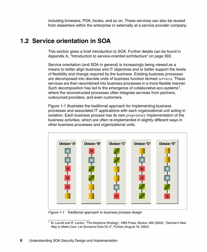
Figure 1-1 illustrates the traditional approach for implementing business processes and associated IT applications with each organizational unit acting in isolation. Each business process has its own proprietary implementation of the business activities, which are often re-implemented in slightly different ways in other business processes and organizational units.
Figure 1-1 Traditional approach to business process design
1 M. Lansiti and R. Levien, “The Keystone Strategy”, HBS Press, Boston, MA (2004), “Daimler’s New Way to Make Cars: Let Someone Else Do It”, Forbes (August 16, 2004)
Division “A” Division “B” Division “C” Division “D” Division “E”
6 Understanding SOA Security Design and Implementation

Figure 1-2 shows the goal of service orientation: common business logic is available in reusable services that can be performed where it is most appropriate, regardless of organizational boundaries.
Figure 1-2 Service-oriented approach to business process design
1.2.1 More than componentization
SOA is more than merely decomposing business processes into components of business function. It also identifies that the focus in application development needs to be on implementing business logic, not on how components will interconnect. This allows services to be connected together to implement the desired business processes. Moreover, services can be replaced with equivalent services as required; for example, a particular business function might be outsourced.
Consider the example shown in Figure 1-3 on page 8, where each service needs to know how to connect to each other service to which it might need to connect. Given our goal of flexible connectivity, determining the scope of potential connectivity can be quite difficult to predict. This tight coupling between services makes the resulting business process fragile and difficult to change to meet the evolving needs of the business.
Outsourced
SupplierSupplier
Shared ServicesShared Services
Division (s)
CustomerCustomer
Chapter 1. Business context 7

Figure 1-3 Directly connected services
As described in 1.1.2, “Service connectivity at a government department” on page 5, by moving functionality, such as flow control, translation of data formats and protocols, and identity propagation between services out of the application logic and into the services infrastructure, we gain greatly improved flexibility as to how services can be interconnected, because each service only needs to know how to connect to the service infrastructure, as shown in Figure 1-4.
Figure 1-4 Connectivity using a service-oriented infrastructure
Shipments
Pricing
SalesOrders
InventoryWeb Orders
Customers
Shipments
Pricing
Web Orders
SalesOrders
Inventory
Customers
Service
Infrastructure
8 Understanding SOA Security Design and Implementation

1.2.2 A focus on reuse
An important differentiation between service orientation and earlier distributed application development approaches is a much stronger focus on reusing existing IT assets. This emphasis on the value of reuse has made a transition to SOA more attractive and affordable for enterprises with large investments in existing IT systems, some dating back over 30 years.
Reusing existing systems does come at a price. Resulting systems comprise a heterogeneous mix of new and old technologies, which presents systems management, compliance, and security management challenges.
As shown in Figure 1-5, one example of a set of functionality that can be externalized and reused is security. In this way, security (for example, identity processing) is decoupled from the services and processed externally.
Figure 1-5 SOA requires security (and identity) abstraction
1.3 Security considerations for SOA
Securing access to information is fundamental for any business. Security becomes even more critical for implementations structured according to SOA principles, due to the loose coupling of services and applications, and their operation across organizational boundaries. Such an environment often exposes
Shipments
Pricing
Web Orders
SalesOrders
Inventory
Customers
Security
SecuritySecurity
Security
SecuritySecurity
ESB
Security
Services
Service
Infrastructure
Chapter 1. Business context 9
the brittleness and limitations of existing security implementations. Based on observed patterns from a set of scenarios, and use cases, we can articulate the required capabilities and create a reference model to address these capabilities.
A secure business needs a flexible, customizable infrastructure, so it can adapt to new requirements and regulations. Merely securing the perimeter with firewalls or routers is not sufficient, because a business needs to have dynamic trust relationships over time with its partners, customers, and employees. To provide such flexibility, a business needs to leverage a security services infrastructure. Businesses must not hard wire policies into the services, but implement the requirements of the security model through a policy driven infrastructure. In order to achieve the vision of meeting business goals through IT in an auditable manner, security policies must be factored in as part of the application life cycle.
Examining the security management challenges, there are a number of considerations in a service-oriented environment that enterprise architects care about:
� The need for identity to be decoupled from the services. All entities in SOA have identities - users, services, and so on, that need to be properly identified so that appropriate security controls can be applied.
� The need to seamlessly connect to other organizations on a real-time, transactional basis
� The need to ensure that, for composite applications, proper security controls are enacted for each service and when services are used in combination
� The need to manage identity and security across a range of systems and services that are implemented in a diverse mix of new and old technologies
� Protection of business data in transit and at rest
� The need for demonstrable compliance with a growing set of corporate, industry, and regulatory standards
1.3.1 User and service identities and their propagation
An SOA aims to provide services that can be interconnected and reused as appropriate to fulfill a particular business process. Moreover, these services must be connected and implemented in a secure and auditable manner, according to a defined security policy. Identity therefore plays a key role in delivering on the promise of service orientation. Figure 1-6 on page 11 shows the identity challenges in SOA.
10 Understanding SOA Security Design and Implementation

Figure 1-6 Identity challenges in SOA
Identities exist for both users and services, and both must be subject to the same controls.
The identities might need to be propagated throughout the SOA environment. In many cases, service implementations can restrict the options and formats available for propagating a user’s identity to/from the service. Identity Services are therefore required in the infrastructure to deal with these identity mediation issues, so that services can be easily interconnected without worrying about how to map and propagate user identity from one service to the next. This approach can greatly reduce the amount of code written and hence improve the speed and ease of developing new services.
1.3.2 Connect to other organizations on a real-time, transactional basis
There are several forms of inter-organization interaction that can occur in a service-oriented deployment. A first step toward service orientation might involve integrating service user interfaces from different domains or organizations into a single portal interface. Another example might involve a service provided by a partner organization being directly invoked from a business process.
Greater number of diverse users Each application/service brings its own IDs and credentialsNeed to decouple identities from the applications
Business flexibility demandsMultiple, heterogeneous endpointsNo more application logic coding – expensive to maintain and support
Compliance concernsMaintain clean user directories in mainframe and lines of businessesFlow auditable application identities from point-of-entry to resources
401K
DesktopID
VPN ID
HR ID
Health Provider ID
NotesID
CorporateTravel ID
SupplyChain ID
IRAAccount
SAP ID
Siebel ID
MS ADNetwork ID
OnlineBank
Account
Financial ServicesAccount
Each application brings its own IDEach ID does not work with other IDsEach ID adds cost and complexityEach ID adds business risk to compliance
Chapter 1. Business context 11

Regardless of the form of the interaction, it is imperative that security, identity, and access policies are defined and enforced for all transactions. These policies need to be enforced for both incoming and outgoing requests.
Boundary security services are an obvious starting point. These boundary security services must be able to provide coarsely grained verification that requests are coming from or going to trusted parties.
Establishing the trust relationship between the organizations is a key step in allowing inter-organization cooperation. This involves establishing rules around interaction, such as defining identity information that must be propagated between organizations, as well as establishing the cryptographic keys used for securing the messages.
It is very unlikely that user identities will be the same in all of the service components in a business process flow that spans different organizations. Identity Services will therefore be required to validate the identity of the requesting user, confirm that they are authorized to perform the requested operation, and map their identity to one that the target service can understand and use to identify the user or service making the request.
1.3.3 Composite applications
The security policy for the services includes the rules established for allowing services to be accessed. A user or service might require specific privileges to allow them to access a service.
When services are combined, such as when they are choreographed into a higher level business process, the combination of these services might require another examination of the security policy. For example, a user might be allowed to access Service A and Service B independently. However, when these two services are choreographed together, perhaps with other service invocations, then the user is no longer allowed to access these services.
The complexity in an SOA environment is that the security policy for the choreographed services needs to take into account the mixing and matching of services in different combinations as required to reflect changes in business processes. Each new choreography might require examination of the security policy to ensure it remains valid for this new combination.
1.3.4 Managing security across diverse environments
A typical SOA will have many points at which security policy is enforced and implemented. These policy enforcement points will be located both at the service connectivity level, as well as within the implementations of the services
12 Understanding SOA Security Design and Implementation
themselves. Management of a policy across these various heterogeneous enforcement points requires an administrator to use a diverse set of resource centric management interfaces, and their associated security policy terminology and semantics. This sometimes is called swivel chair management.
For SOA to achieve its goal of business flexibility within an environment of governance and regulatory compliance, definition and management of security policy need to be simplified. There must be consistent management terminology and semantics across the various enforcement points. This defined policy can then either be directly enforced by the enforcement points or automatically translated into something that the endpoints can understand and enforce.
1.3.5 Protecting data
Protection of data from unauthorized modification and disclosure is a key requirement within SOA. Data needs to be protected because it is business or privacy sensitive or both. A policy must therefore be in place to ensure that data is protected in both transit and at rest, with consistent security measures applied.
Data protection is especially important when data moves outside the organizational boundary, which can happen without the knowledge of the consumer. For example, an internal service might be replaced with an outsourced service, with data now flowing to the external organization. If the data is business or privacy sensitive, then the service provider might need to ensure appropriate protection is in place to satisfy the policy requirements of the calling organization.
1.3.6 Compliance with a growing set of regulations
Auditing of transactions is required to provide the data needed for assessing compliance, which measures the performance of the IT environment relative to measures established by the business policies. This might include verifying the working system against a set of internally created policies and also against external regulatory acts.
Complexity is increased in SOA where different applications from different sources or vendors are targeted for different levels of compliance. This is especially true when accessing services provided by an external organization, where the regulatory and compliance regime is different from the requesting organization.
If possible, the audit data produced by the various policy enforcement points must be integrated into a single repository, or federated into a single logical view of the data. This will facilitate the production of the required audit reports,
Chapter 1. Business context 13

verification of compliance against policy, and investigation of security-related events.
1.4 Security in the service-oriented life cycle
An important facet of service orientation is an emphasis on the entire life cycle of IT systems—from conception to ongoing operation and management. Service orientation aims to better align business and IT goals and to provide a greatly improved capability to deal with change. Refer to Appendix B, “IBM SOA Foundation” on page 415 for more information about the SOA life cycle model.
1.4.1 Security encompasses all aspects of the life cycle
As shown in Figure 1-7, certain roles in an organization contribute toward the creation, definition, refinement, monitoring, verification, and management of security policies during the execution of the service-oriented life cycle.
Figure 1-7 Service-oriented life cycle from a security perspective
14 Understanding SOA Security Design and Implementation
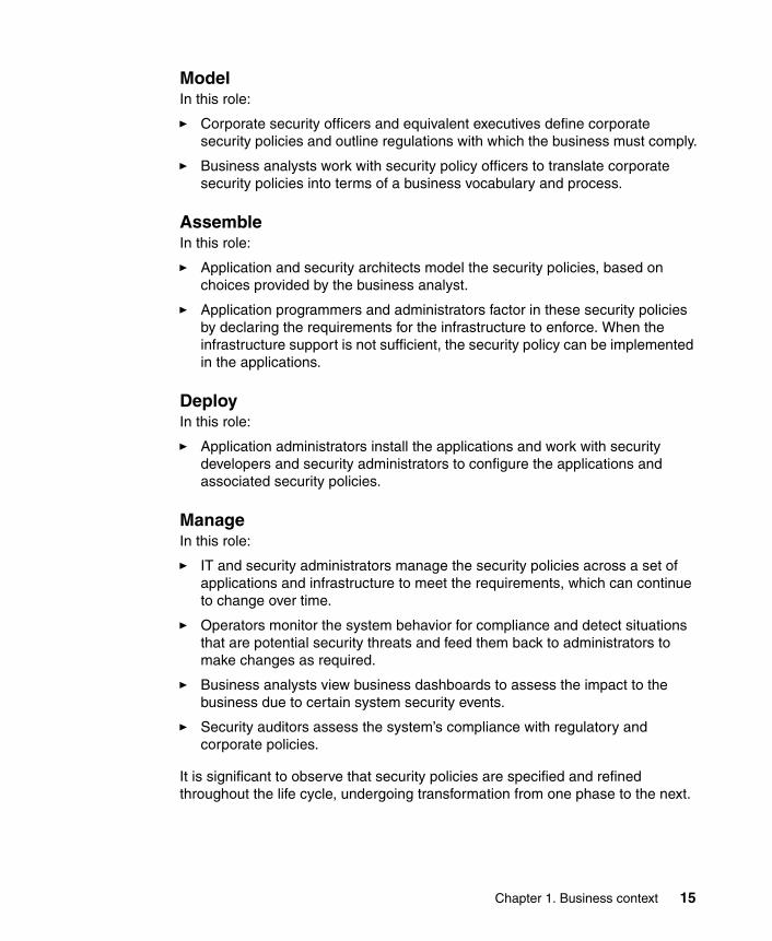
ModelIn this role:
� Corporate security officers and equivalent executives define corporate security policies and outline regulations with which the business must comply.
� Business analysts work with security policy officers to translate corporate security policies into terms of a business vocabulary and process.
AssembleIn this role:
� Application and security architects model the security policies, based on choices provided by the business analyst.
� Application programmers and administrators factor in these security policies by declaring the requirements for the infrastructure to enforce. When the infrastructure support is not sufficient, the security policy can be implemented in the applications.
DeployIn this role:
� Application administrators install the applications and work with security developers and security administrators to configure the applications and associated security policies.
ManageIn this role:
� IT and security administrators manage the security policies across a set of applications and infrastructure to meet the requirements, which can continue to change over time.
� Operators monitor the system behavior for compliance and detect situations that are potential security threats and feed them back to administrators to make changes as required.
� Business analysts view business dashboards to assess the impact to the business due to certain system security events.
� Security auditors assess the system’s compliance with regulatory and corporate policies.
It is significant to observe that security policies are specified and refined throughout the life cycle, undergoing transformation from one phase to the next.
Chapter 1. Business context 15

1.5 Summary
The overall security principles that apply in any environment, whether SOA or not, are the same: identity, authentication, authorization, confidentiality, integrity, audit and compliance, policy management, and availability2. What changes in SOA is how they are applied.
Security management permeates all aspects of the service-oriented life cycle and is a key enabler for achieving the connectivity and flexibility goals of service orientation.
Examination of high level requirements for security management in SOA highlights the following aspects:
� Security is a business requirement, not just technology.
� Enterprise architects care about SOA identity and security challenges, because they have visibility of the big picture.
� SOA environments start to emphasize some key security challenges:
– The need for user and service identities and propagation of these identities across the organization.
– The need to seamlessly connect to other organizations on a real-time, transactional basis.
– The need to ensure for composite applications that proper security controls are enacted for each service and when used in combination.
– The need to manage identity and security across a range of systems and services that are implemented in a diverse mix of new and old technologies.
– Protection of data in transit and at rest.
– The need for demonstrable compliance with a growing set of corporate, industry, and regulatory standards.
� SOA security needs to encompass the full life cycle of development through model, assemble, deployment, and management of SOA applications.
2 Refer to Appendix C, “Security terminology, standards, and technology” on page 439 for information about these principles.
16 Understanding SOA Security Design and Implementation

Chapter 2. Architecture and technology foundation
In this chapter, we describe how security can be applied to a service-oriented architecture (SOA). SOA applications are built from composable services across a distributed environment. Securing this environment is both critical and challenging.
We begin by introducing three IBM SOA Foundation Scenarios and discussing the security aspects of these scenarios. Next, we describe a typical deployment architecture for these scenarios and identify key security deployment considerations. From these discussions, we derive the requirements for the IBM SOA Security Reference Model and then describe this model. We finish by outlining an architecture decision guide and show IBM product mappings for the IBM SOA Security Reference Model.
2
© Copyright IBM Corp. 2007. All rights reserved. 17

2.1 SOA security logical architecture
In this section, we discuss the technical aspects of business scenarios introduced in Chapter 1, “Business context” on page 3. These are typical SOA scenarios/use cases where various aspects of security need to be considered. We use these scenarios to derive a logical deployment architecture.
2.1.1 Foundation scenarios
IBM SOA Foundation Scenarios are a set of reusable assets that can help speed up the process of adopting SOA. This section briefly describes three of the IBM SOA Foundation Scenarios and several of the security issues involved. More details are included in the following chapters.
Service Creation scenarioThis scenario depicts the situation described in 1.1.1, “Service creation at an insurance company” on page 4 where existing business logic is to be enabled as a service, or a new service is to be deployed. For example, access to business logic from an enterprise information system, such as CICS, falls into this category. In these cases, a service veneer can be built to allow access to an existing business application. For example, you might build a Web service implementation using a J2EE™ application to provide this veneer. In these cases, an application server that provides an SOA runtime environment can host this new service that publishes the capabilities through a service interface. Security is an important consideration in this case; it is not only important to protect the message but to identify who is invoking the service and to be able to audit that action. It is also important to provide a seamless user experience so that the intermediate veneer is transparent to the user.
Note: In our following discussions and in many current publications, the terms service requestor and service consumer are used interchangeably.
18 Understanding SOA Security Design and Implementation

Figure 2-1 IBM SOA Foundation Scenarios: Service Creation
Securing access to a service can be handled using declarative security so that the application does not handle security, but lets the runtime hosting the service (application server container) provide the necessary security enforcement.
For more information, see Chapter 3, “IBM SOA Foundation Service Creation scenario” on page 67, which focuses on applying the IBM SOA Security Reference Model to the Service Creation scenario.
Service Connectivity scenarioThere are situations similar to the scenario in 1.1.2, “Service connectivity at a government department” on page 5 where an organization has a set of core services or systems that are to be made available as services to a variety of internal and external systems and users. The flexibility to make changes to these services and service implementations with minimal to no impact to service consumers is desirable. In these cases, an Enterprise Service Bus (ESB) can provide the necessary decoupling of service consumers from service providers. As shown in Figure 2-2 on page 20, consumer’s systems can also use different protocol bindings compared to what the services provide.
In these cases, it is important to protect business information and establish business trust relationships for identity, data, and so on. Because the requests might come from the external entities, security domains are likely to be crossed. Consequently, the propagation of identity across domains is also a key consideration. In addition, the organization needs to consider the appropriate governance and compliance measures to address a variety of legal and regulatory aspects.
Service Interface
Service Consumer
Existing business application
Service Consumer
Chapter 2. Architecture and technology foundation 19
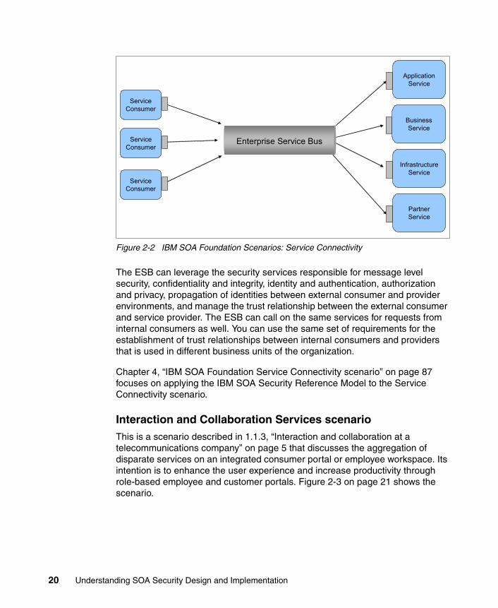
Figure 2-2 IBM SOA Foundation Scenarios: Service Connectivity
The ESB can leverage the security services responsible for message level security, confidentiality and integrity, identity and authentication, authorization and privacy, propagation of identities between external consumer and provider environments, and manage the trust relationship between the external consumer and service provider. The ESB can call on the same services for requests from internal consumers as well. You can use the same set of requirements for the establishment of trust relationships between internal consumers and providers that is used in different business units of the organization.
Chapter 4, “IBM SOA Foundation Service Connectivity scenario” on page 87 focuses on applying the IBM SOA Security Reference Model to the Service Connectivity scenario.
Interaction and Collaboration Services scenarioThis is a scenario described in 1.1.3, “Interaction and collaboration at a telecommunications company” on page 5 that discusses the aggregation of disparate services on an integrated consumer portal or employee workspace. Its intention is to enhance the user experience and increase productivity through role-based employee and customer portals. Figure 2-3 on page 21 shows the scenario.
Application Service
Enterprise Service Bus
Service Consumer
Service Consumer
Service Consumer
Business Service
Infrastructure Service
Partner Service
20 Understanding SOA Security Design and Implementation

Figure 2-3 IBM SOA Foundation Scenarios: Interaction and Collaboration
Improved user experience from single sign-on to all of the applications, self-care, and profile management are very important in this scenario. A user only needs to be identified/authenticated once, and then the user is able to access all of the applications for which they are authorized. The portal provides access to internal service provider applications. A service that has already been exposed can be reused in this scenario. Securing the connection from the portal to the internal service providers, providing the security tokens, and utilizing identity mapping might all be required.
In the case where the portal accesses external service providers, the use of identity propagation techniques for security token and identity mapping are also relevant. The organization’s portal can make requests to the external portals as well. For example, the Web Services for Remote Portlets (WSRP) standard can be used. The same security requirements exist that are used for the external service provider case.
There is also the case where we need federated single sign-on to enable the users to access the external portal from their browser without the need to sign in again. Protocols, such as Security Assertion Markup Language (SAML) or WS-Federation, can be used in this case and again require the identity federation services. Because a number of application domains are being traversed, it is imperative to provide accountability for a user’s identity that is propagated to all applications and service providers.
Application Service
ServiceConsumer Enterprise Service Bus
Portal & Collaboration
PervasiveAccess
Remote Portlets(WSRP)
Partner Service
Partner Service
Chapter 2. Architecture and technology foundation 21

Chapter 5, “IBM SOA Foundation Interaction and Collaboration Services scenario” on page 101 focuses on applying the IBM SOA Security Reference Model to the Interaction and Collaboration Services scenario.
2.1.2 Logical deployment architecture
Based on the scenarios in the previous section, Figure 2-4 shows a typical logical deployment architecture.
In most situations, there is a proxy (HTTP or Web services gateway) deployed in the demilitarized zone (DMZ) in front of either a Web application or portal server. The Web application/portal server leverages existing applications/services either directly or through an ESB. Clients can be users or service consumers, both internal or external. Similarly, existing applications/services can be either internal or external.
In this type of a deployment, security is enforced at various points within the architecture. The proxy can enforce confidentiality and integrity, identity validation, authentication, and auditing. The identity derived at the proxy might need to be propagated to the application server where the propagated identity needs to be accepted and additional security checks, such as authorization, can be enforced, as well as auditing this activity. Further security enforcement can be performed by the other components within the architecture as well.
Figure 2-4 Typical logical deployment architecture for an SOA application
Client System(browser,rich client)
Proxy
Fire
wal
l Web Application Server/Portal
Server
ExistingApplication
ESB
EnterpriseInformation
System
Data Server/Services
PartnerApplication
Fire
wal
l
Message Security
Transport Security
Propagate identityApplication level authorization
Propagate identityFine level authorizationAudit
Federate Identities with partnersAuditingConfidentiality and Integrity
22 Understanding SOA Security Design and Implementation

Two main observations that can be derived from this environment are:
� Security infrastructure integration challenge: Because each component is enforcing an aspect of security, there can be multiple identity and authentication systems, multiple authorization engines, and multiple audit logs. In a typical environment, these security systems are not well integrated and therefore can be considered a challenge in an SOA environment.
� Security management challenge: From a management perspective, there are multiple islands of administration specific to products and usually prone to error, inconsistency, and lack of coordination. Management can be resource-centric, and policy management is isolated to a business unit, application, or product. This makes for a challenge in an SOA environment where consistent policies need to be enforced across multiple components of the architecture.
These observations need to be factored in (and addressed) when developing the IBM SOA Security Reference Model. So let us have a closer look at them in the following order:
� “Identity propagation, mapping, and provisioning” on page 23� “Authorization” on page 27� “Audit” on page 28� “Data Protection” on page 31
Identity propagation, mapping, and provisioningIn this sub-section, we look into the challenges around identity and the elements of a proposed solution.
ChallengesFigure 2-5 on page 24 illustrates one of the challenges faced in SOA environments, that of identity propagation and mapping.
In this example, user John Doe is authenticated at the proxy as jdoe. The proxy determines if the user is authorized to access the Web application server/portal server. If so, the request and identity are propagated to the Web application server/portal server. This identity, commonly termed an authenticated identity, is then used by the Web application server/portal server for its own authorization and auditing.
Chapter 2. Architecture and technology foundation 23

Figure 2-5 Identity propagation and mapping example
The Web application server/portal server then generates requests to either an Enterprise Information Server (EIS), an ESB, or an existing application:
� Enterprise Information Server (EIS): This is a back-end system (for example, CICS or IMS™) receiving requests directly from the Web application server/portal server. An identity mapping is required to transform jdoe into an identity suitable for the EIS (z42). There are two choices of identity mapping:
– Map jdoe into John Doe’s identity on the EIS. This requires a one-to-one mapping of user identities. This case is suitable when the EIS needs to perform authorization or auditing using John Doe’s identity.
– Map jdoe into an administrative or system identity on the EIS. This case is suitable when the EIS only requires a common administrative identity (perhaps the user’s role) for authorization and auditing. The EIS does not need to know who the user is.
Both cases introduce their own identity management concerns and might not adhere to some of the compliance requirements. Other than identity mapping, there is also an issue of identity token format. For example, jdoe might be represented as a Kerberos ticket whereas the z42 identity token might include a RACF® passticket. Hence, there are two challenges: identity mapping and identity token translation.
� Enterprise Service Bus (ESB): The ESB receives service requests. These requests propagate John Doe’s identity jdoe so no mapping is required at the creation of these requests. However, at the ESB, three identity mappings/identity format translations are required:
– EIS: Same mapping as described above.
– Data server/services: This is a back-end data system (for example, DB2® Database) receiving requests from the ESB. An identity mapping is required to map jdoe to the data server’s identity, in this case d_admin. In a similar way to the EIS, this server requires either a user’s identity or an
Client System(browser,rich client)
Proxy
Fire
wal
l Web Application Server/Portal
Server
ExistingApplication
ESB
EnterpriseInformation
System
Data Server/Services
PartnerApplication
Fire
wal
l
John Doe jdoe
jdoe
jdoe
z42
d_admin
ibm_empl
z42
jdoe
24 Understanding SOA Security Design and Implementation

administrative identity. It also requires the identity format to be altered into the correct representation.
– Partner application: It is very likely that this application is situated within another organization. The request from the ESB needs to propagate the identity expected at the business partner, in this case, ibm_empl. In a similar way to the EIS and data server cases, this server requires either a user’s identity or an administrative identity.
� Existing Application: This application requires the same jdoe identity to be propagated and no identity mapping is required.
Figure 2-6 illustrates the related challenges faced in the SOA environments, those of identity provisioning. There are typically many user registries that exist in the environment. An organization might use RACF for the EIS, a database for the data services, Microsoft® Active Directory®, Tivoli Directory Server, and potentially a number of other LDAP compatible user registries as well. User identities created on these systems must be in accordance with policy and be up-to-date with changing user circumstances.
Figure 2-6 Identity provisioning example
Elements of a solutionTo address the requirements of identity propagation, mapping, and provisioning, an ideal solution needs to include both business and technical aspects.
From a business view, we need:
� Trust Management: Trust is fundamental to managing risk and security. Managing trust relationships between systems/businesses and reflecting the relationship in business transactions, system deployments, and service policies is important.
� Identity and Access Management: Business aspects to deal with the management of identities both within an enterprise, as well as across
Client System(browser,rich client)
Proxy
Fire
wal
l Web Application Server/Portal
Server
ExistingApplication
ESB
EnterpriseInformation
System
Data Server/Services
PartnerApplication
Fire
wal
l
John Doe jdoe
jdoe
jdoe
z42
d_admin
ibm_empl
z42
jdoe
User Registry
User Registry
User Registry
User RegistryUser
Registry
Chapter 2. Architecture and technology foundation 25

enterprises. This also includes management of access policies to resources based on identity information and resource information.
From a technical view, we need:
� Identity and Authentication Services: A standards-based service to handle which user identity is passed, and how is it passed. For example, WS-Trust defines a mechanism for security token exchange to validate and issue credentials within different trust domains.
Similarly, we need a standards-based framework for provisioning identities in a consistent way based on business policies. For example, WS-Provisioning and Service Provisioning Markup Language (SPML) provide a framework for managing the provisioning and allocation of identity information and system resources within and between organizations.
� Policy Management: A mechanism to create policies based on business drivers and influencing factors (such as trust and identity) and to distribute them in a consistent manner to all the relevant components within a logical deployment architecture. A policy infrastructure is important to keep track of policy life cycle management, adhere to governance and compliance requirements, and ensure the enforcement of correct policies.
This solution can be delivered as shown in Figure 2-7 on page 26.
Figure 2-7 Addressing the requirements around identity propagation and mapping
Client System(browser,rich client)
Proxy
Fire
wal
l Web Application Server/Portal
Server
ExistingApplication
ES
B
EnterpriseInformation
System
Data Server/Services
PartnerApplication
Fire
wal
l
John Doe jdoe
jdoe
jdoe
z42
d_admin
ibm_empl
z42
jdoe
Identity and Access Trust Management Policy Management
Identity Services Authentication Services Policy Enforcement
26 Understanding SOA Security Design and Implementation

AuthorizationIn this sub-section, we look into the challenges around authorization and the elements of a proposed solution.
ChallengesFigure 2-8 on page 27 illustrates another of the challenges faced in the SOA environment, that of providing consistent authorization across the environment.
Authorization is required from every component in turn, from very coarse-grained (application level) to very fine-grained (data level). For example, a Web service in a financial institution:
� The proxy can implement service level authorization, for example, access to a Web service for insurance quoting.
� The application server can implement operation level authorization, for example, access to an operation that retrieves an individual’s insurance history.
� The ESB can implement authorization to the data server, for example, access to a data server specific to the geography of the individual.
� The data server can provide authorization based on specific data, for example, access to sensitive personal information of the particular individual.
This highlights the policy complexity in authorization, as the authorization gets more fine-grained, so does the complexity in consistent policy management.
Figure 2-8 Authorization example
Elements of a solutionTo address the requirements of authorization, an ideal solution needs to include both business and technical aspects. From a business view, we need:
Client System(browser,rich client)
Proxy
Fire
wal
l Web Application Server/Portal
Server
ExistingApplication
ESB
EnterpriseInformation
System
Data Server/Services
PartnerApplication
Fire
wal
l
Authorization
Chapter 2. Architecture and technology foundation 27

� Identity and Access Management: Business aspects to deal with the management of identities both within an organization, as well as across organizations. This also includes management of access policies to resources based on identity information and resource information.
From a technical point of view, we need a standards-based approach to handle the authorization issues end-to-end. For example, eXtensible Access Control Markup Language (XACML) is a standard for access control systems. It describes both a common language for expressing access control policies to describe general access control requirements and a request/response language that describes how to form a query to determine if a given action is allowed or not and how to interpret the result.
The solution can be delivered as shown on Figure 2-9 on page 28.
Figure 2-9 Addressing the requirements around authorization
Again a mechanism is needed to create policies based on business drivers and influencing factors and distribute them in a consistent manner to all the relevant components within a logical deployment architecture. A policy infrastructure is important to keep track of policy life cycle management, adhere to governance and compliance requirements, and ensure the enforcement of correct policies.
AuditIn this sub-section, we look into the challenges around auditing and the elements of a proposed solution.
Client System(browser,rich client)
Proxy
Fire
wal
l Web Application Server/Portal
Server
ExistingApplication
ES
B
EnterpriseInformation
System
Data Server/Services
PartnerApplication
Fire
wal
l
Policy Enforcement
Identity and Access Policy Management
AuthorizationServices
28 Understanding SOA Security Design and Implementation

ChallengesFigure 2-10 on page 30 illustrates another one of the challenges faced in the SOA environment, that of providing access to consistent audit information across the environment.
Audit information is required to be gathered from every component along the transaction path. That is, important events need to be logged and available for real-time or later forensic review. These events can be security specific, for example, authentication, authorization, identity mapping, identity provisioning, and policy management-related, or they can be of a more general nature, such as data or application access.
There are a number of challenges in implementing audit:
� Audit information is often physically located on the server that generates the event. For example, for all the different components, such as proxy, Web application server/portal server, and the ESB, a back-end database might write events to each component’s log file. This distribution of audit log information makes it difficult to later trace the events of a transaction end-to-end, because each log needs to be accessed. Additionally, different tools might be required to access this log information.
� Audit log format is often different on every component that generates an event. This is especially true when there is a heterogeneous mixture of middleware and applications. Real-time or forensic inspection of these logs becomes a difficult process of trying to understand the different log formats and collate related events.
� Compliance to internal or regulatory policy is very difficult to check. There is no automated way of knowing if the security events that are being generated by the individual components are indicating compliance with policy or not.
These three factors make it challenging to generate the correct log information and then verify compliance of the end-to-end system with internal and regulatory policy.
Chapter 2. Architecture and technology foundation 29

Figure 2-10 Audit example
Elements of a solutionTo address the requirements of audit, an ideal solution needs to include both business and technical aspects. From a business view, we need:
� Compliance and Reporting: Measures the performance of the business/IT system relative to the measures established by the business controls and policies. These can be realized based on reporting on system behavior using audit log information and comparing that behavior to defined policies.
From a technical point of view, we need a way to generate audit events end-to-end for transactions, collate these into a common format, and allow real-time and post processing of events for reporting. We also need ways to verify if these events are compliant with policy.
The solution can be delivered as shown on Figure 2-11.
Client System(browser,rich client)
Proxy
Fire
wal
l Web Application Server/Portal
Server
ExistingApplication
ESB
EnterpriseInformation
System
Data Server/Services
PartnerApplication
Fire
wal
l
Audit
30 Understanding SOA Security Design and Implementation

Figure 2-11 Addressing the requirements around audit
A mechanism is needed to create audit policies based on business drivers and influencing factors and distribute them in a consistent manner to all the relevant components. A policy infrastructure is important to keep track of policy life cycle management, adhere to governance and compliance requirements, and ensure the enforcement of correct policies.
Data ProtectionIn this sub-section, we look into the challenges around data protection and elements of a proposed solution.
ChallengesFigure 2-12 on page 32 illustrates another of the challenges faced in the SOA environment, that of providing consistent data protection in the environment.
Starting at the left of the figure, examples of both message protection and transport level protection are shown between many of the components. The data protection policy dictates what type of protection is required.
Additionally, the figure shows data encryption used on the data server. This might be implemented by the native database encryption available, for example on a DB2 database. Which data is protected is dictated by the policy in place.
Client System(browser,rich client)
Proxy
Fire
wal
l Web Application Server/Portal
Server
ExistingApplication
ES
B
EnterpriseInformation
System
Data Server/Services
PartnerApplication
Fire
wal
l
Policy Enforcement
Compliance and Reporting Policy Management
AuditServices
Chapter 2. Architecture and technology foundation 31

Figure 2-12 Data Protection example
Elements of a solutionTo address the requirements of data protection, an ideal solution needs to include both business and technical aspects.
From a business view, we need:
� Data Protection, Privacy, and Disclosure Control: For managing the policies around how data needs to be protected in transit and at rest. This also includes interpretation of any privacy specific policies.
From a technical point of view, we need:
� Confidentiality and Integrity Services: A standards-based service to handle the data protection issues end-to-end. For example, Secure Sockets Layer (SSL) is the most common example of a secure transport level scheme. With SSL, the whole data stream is protected at a protocol level below the application layer. SSL is normally the protocol used to protect traffic between a Web browser and Web server.
The WS-Security specification provides message-level security. The advantage of using WS-Security instead of SSL is that it can provide end-to-end message level security. This means that the messages are protected even if the message traverses through multiple services, or intermediaries. Additionally, WS-Security is independent of the transport layer protocol. It can be used for any SOAP binding, not just for SOAP over HTTP.
The solution can be delivered as shown on Figure 2-13.
Client System(browser,rich client)
Proxy
Fire
wal
l Web Application Server/Portal
Server
ExistingApplication
ESB
EnterpriseInformation
System
Data Server/Services
PartnerApplication
Fire
wal
l
Message Security
Transport Security
Message Security
Transport Security
Transport Security
DataEncryption
32 Understanding SOA Security Design and Implementation

Figure 2-13 Addressing the requirements around data protection
Similar to the previous cases, we need a mechanism to create policies based on business drivers and influencing factors (message protection, privacy rules) and distribute them in a consistent manner to all the relevant components within a logical deployment architecture. A policy infrastructure is important to keep track of policy life cycle management and adhere to governance and compliance requirements and ensure the enforcement of correct policies.
2.1.3 SOA security logical architecture
We can extend the solution aspects from the previous examples to derive a general view of the SOA security logical architecture as shown in Figure 2-14 on page 34.
In this architecture, we can clearly define three tiers:
� Business Security Services. These are the security aspects of the business that need to be defined for successful and secure operation of an enterprise. These are based on a number of influencing factors specific to the industry, such as governing laws, competition, and so on. Business Security Services drive policies within an enterprise that need to be enforced at all relevant points within the infrastructure. Business Security Services hence address the what to accomplish.
Client System(browser,rich client)
Proxy
Fire
wal
l Web Application Server/Portal
Server
ExistingApplication
ES
B
EnterpriseInformation
System
Data Server/Services
PartnerApplication
Fire
wal
l
Policy Enforcement
Policy ManagementData Protection,
Privacy and Disclosure Control
Confidentiality Services Integrity Services
Chapter 2. Architecture and technology foundation 33

� IT Security Services are the building blocks to provide security functions as services. IT Security Services hence address the how to accomplish the definitions put forward by the Business Security Services.
� Security Policy Management. As a part of the overall policy management, security policies need to be derived from Business Security Services and consistently enforced within an infrastructure. Security Policy Management not only provides security policy life cycle management but also policy distribution and transformation. Security Policy Management provides the bridge between the Business and IT Security Services.
Figure 2-14 SOA Security logical architecture
As we have seen before, there are multiple security enforcement points within an SOA environment. These enforcement points derive consistent, coordinated, business driven policies from the Security Policy Management. These policies are based on metadata that can be derived from service registries when available. Because the applications are shared/reused, the applicable policies to address changing needs, heterogeneous application platforms, and protocols (across organizations and vendors) are easily accommodated.
Policies are distributed not only to different enforcement points but also to IT Security Services. These IT Security Services can be either available locally (within a browser) or can be leveraged by centralized services (the proxy taking advantage of external enterprise identity and authentication services).
Client System(browser,rich client)
Proxy
Fire
wal
l Web Application Server/Portal
Server
ExistingApplication
ESB
EnterpriseInformation
System
Data Server/Services
PartnerApplication
Fire
wal
l
Policy Enforcement
Business Security Services
Security Policy Management
IT Security Services
34 Understanding SOA Security Design and Implementation

2.2 Capabilities for a security reference model
This section expands on the capabilities described in 2.1.2, “Logical deployment architecture” on page 22 and 2.1.3, “SOA security logical architecture” on page 33.
2.2.1 Business Security Services
These services involve managing the needs and requirements of the business, such as identity and access management, data protection, governance, risk, and compliance. Business Security Services can be classified into six solution categories as depicted in Figure 2-15.
Figure 2-15 Business Security Services
Compliance and ReportingCompliance management measures the performance of the business/IT system relative to the measures established by the business controls and policies. These can be realized based on reporting on system behavior using audit information (about all events, and not limited to security events), and comparing that behavior to configured policies in systems. When these are viewed in the context of business-defined policies, they provide a overarching view of where a business stands in implementation and enforcement of intended policies.
This might include verifying the working system against a set of internally created policies, and also against external laws or regulatory acts. Some examples of regulations are Basel II1, Sarbanes-Oxley Act2 (SOX), Gramm-Leach-Bliley Act3 (GLBA), ISO/IEC 270024 (formerly ISO/IEC 17799), Federal Information Security
1 For more information about Basel II, go to http://www.bis.org/publ/bcbsca.htm2 For more information about the Sarbanes-Oxley Act, go to http://www.soxlaw.com/3 For more information about the Gramm-Leach-Bliley Act, go to http://www.ftc.gov/privacy/glbact/glbsub1.htm
4 For more information about ISO/IEC 27002, go to http://www.iso27001security.com/html/27002.html
Business Security Services
Compliance and Reporting
Identity and Access Trust Management
Data Protection, Privacy and Disclosure
Control
Non-repudiation Services
Secure Systems and Networks
Chapter 2. Architecture and technology foundation 35

Management Act5 (FISMA), Health Insurance Portability and Accountability Act6 (HIPAA), Australian Privacy Act7, and UK Data Protection Act8.
Audit records form the basis of the raw data required for compliance assessments. The compliance function can be a manual process, or an automated tool can be used to reconcile the business compliance requirements with the raw data extracted from the Audit Services.
Managing the audit data involves assessing the implementation of the security elements of the SOA solution against the solution design. It might also help you attempt to identify inconsistencies among the configurations of multiple instances of a solution component that need to share an identical security configuration. A third aspect is the verification of the configuration of the security services themselves. Periodic auditing of the components and overall SOA solution are recommended.
Data Protection, Privacy, and Disclosure ControlInformation and content protection capability provide the ability to safeguard information, such as customer and employee information, financial information, and so on. This is done through policy-based access enforcement, data encryption, data and application isolation support provided in hardware, operating systems, and middleware. A privacy control capability helps reduce privacy compliance costs by automating manual procedures, builds trust by managing user consent to privacy policies, externalizes data handling rules from applications’ IT systems, and gets detailed reports on access to sensitive information to facilitate audit requirements.
Data protection management deals with protecting business information and provides the capabilities for data protection in transit and at rest. It includes policies for which data is to be protected and to what extent it can be specified and implemented. Externalizing data handling rules from applications and IT systems can help to simplify the management of data protection.
Business policies are needed to define data protection policies for use in transit and at rest. Processes are needed in the event of misuse and inappropriate use of data. Business policies are also needed to define the sensitivity of data and to apply the appropriate message protection and privacy policies.
5 For more information about the Federal Information Security Management Act, go to http://csrc.nist.gov/groups/SMA/fisma/index.html
6 For more information about the Health Insurance Portability and Accountability Act, go to http://www.hhs.gov/ocr/hipaa/
7 For more information about the Australian Privacy Act, go to http://www.privacy.gov.au/8 For more information about the UK Data Protection Act, go to http://www.opsi.gov.uk/acts/acts1998/19980029.htm
36 Understanding SOA Security Design and Implementation

In the context of information and business information privacy, the disclosure control capability helps reduce privacy compliance costs by automating manual procedures. The system builds trust by:
� Publishing a privacy policy for users to view and understand.
� Managing user consent to privacy policies.
� Capturing user preferences (such as opt-in to release personally identifiable information (PII) for certain purposes).
� Getting detailed reports on access to sensitive information.
Non-repudiation Services Non-repudiation Services allow for protection of the requestor and the provider from false denials that data has been sent or received. Non-repudiation Services provide proof of data origin and delivery. They aim to prevent parties in a communication from falsely denying having taken part in that communication; for example, a non-repudiation service for digitally certified mail ensures that the sender cannot deny having sent the message and the receiver cannot deny having received it.
Non-repudiation is a business service, likely to be implemented in terms of IT Security Services, such as audit, confidentiality, and integrity. The Non-repudiation Services implemented by cryptographic mechanisms provide the following functions:
� Proof of origin of data� Proof of submission of data� Proof of transport of data� Proof of delivery of data
The Non-repudiation Service is different from the Confidentiality and Integrity Services (per the ISO 7498-2 guideline). Non-repudiation is critical for Electronic Data Interchange (EDI) security and thus is a strategic element of the model. Today, the digital signature mechanism is commonly the principal implementation of a non-repudiation service.
Identity and AccessProcesses for managing identity can include provisioning and de-provisioning identities and self-care/self-registration for optimal user interaction. Identity and Access can also include processes and policies for approval of access to IT resources and business resources. In addition, policies for password management and identity management are also applicable.
Chapter 2. Architecture and technology foundation 37

Identity and Access also deals with identities both within an enterprise, as well as across enterprises. It also includes management of access policies to resources based on identity information and resource information.
Identity life cycle management is important. Identities need to be created, modified over time, and eventually deleted. Important aspects of Identity and Access are:
� Identity feed: Often the authoritative source of identity information for internal users is the human resources (HR) system. An identity feed from the HR system can indicate, to the identity management system, that changes to the user population have occurred, and provisioning workflows need to be initiated.
� Approvals: Before accounts on end systems are created or modified, approvals from the appropriate management might be required. This can be automated.
� Re-validation: Access to systems might need to be approved at regular intervals. The system collects the appropriate revalidation approvals.
� User self-care: Users of the system must be able to perform certain tasks without input from an administrator. For example, they might want to self-enroll to the system, reset or change their passwords, and so on.
� Delegated administration: For approving requests for accounts and other administrative functions, delegating the action to another user or users is an important function.
Trust ManagementTrust Management addresses trusted relationships between entities, such as organizations, enterprises, identities, security domains, and systems. These relationships can be system-to-system, business-to-business, and so on.
Trust Management deals with two aspects, namely business and technology. The business aspect deals with two entities agreeing upon a set of rules to conduct business. These rules include relationship management, liability management, and other legal and contractual aspects.
Business processes and policies are required for establishing trusted relationships. These processes can include which legal process to follow and the process used for evaluating liability. This can also include the policies specific to resource access.
The technology aspect deals with managing the infrastructure that supports the capability for establishing trust by cryptographic methods. These include key management (strength, key validation, and so on) protocols, attributes, and other technical considerations for establishing trust.
38 Understanding SOA Security Design and Implementation
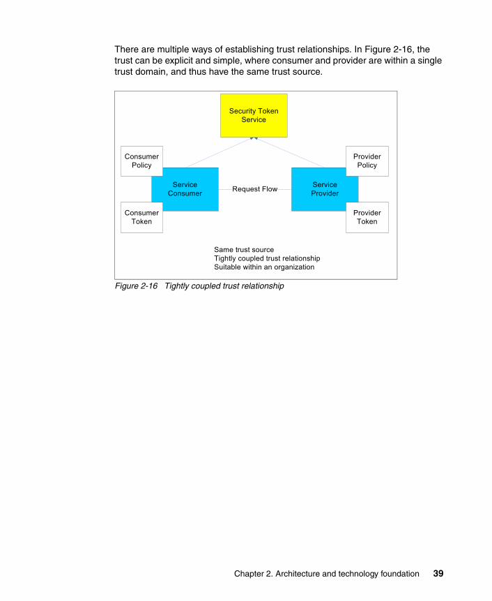
There are multiple ways of establishing trust relationships. In Figure 2-16, the trust can be explicit and simple, where consumer and provider are within a single trust domain, and thus have the same trust source.
Figure 2-16 Tightly coupled trust relationship
Security Token Service
ServiceConsumer
Service ProviderRequest Flow
ConsumerPolicy
ProviderPolicy
ConsumerToken
ProviderToken
Same trust sourceTightly coupled trust relationshipSuitable within an organization
Chapter 2. Architecture and technology foundation 39

In Figure 2-17, we illustrate another approach where a consumer and a target service might have separate trust zones and trusted relationship, or a trusted third-party security token service.
Figure 2-17 Loosely coupled trust relationship
Secure Systems and Networks Business policies are required for intrusion detection and event management for ensuring Secure Systems and Networks. Processes must be in place for handling alerts, for engaging the Computer Emergency Response Team (CERT), and for normal housekeeping of scheduled maintenance, patch management, and servicing.
This is a category of technologies and embedded systems that help protect infrastructure servers, systems, and networking resources from security threats. The desire is to protect the systems from external and internal threats, such as malicious hackers and malware.
Firewalls are used whenever there is a need to control the traffic between two networks. For example, a firewall is used at the connection of the perimeter of an organization and the Internet and can provide simple protocol and port filtering, or more complex protocol inspection. Newer types of firewalls, such as XML
Security Token Service
ServiceConsumer
Service ProviderRequest Flow
ConsumerPolicy
ProviderPolicy
ConsumerToken
ProviderToken
Separate trust sourcesLoosely coupled trust relationshipOptional 3rd party trust providerSuitable between organizations
Security Token Service
3rd partyTrust Provider
40 Understanding SOA Security Design and Implementation

firewalls, inspect XML and SOAP traffic and can provide protection against higher-level protocol specific attacks.
Operating system security involves the hardening of commercial operating systems so that they can provide greater security controls. For example, one issue with UNIX operating systems is that the administrative user (root) has full control, including the ability to delete all security audit logs. In this case, operating system security software can control and securely log the access of root to applications and data, providing improved security, accountability, and separation of duties.
Intrusion detection (host and network) is concerned with identifying malicious attacks on hosts and the network itself. These types of tools can prevent attackers from taking advantage of unpatched systems and mis-configured networks. These types of tools can also enforce policies at much more granular levels to ensure the threat surface area is at a minimum. This might be used, for example, to detect external or internal intrusions to these systems. Network-based anomaly detection systems (ADS) are concerned with discovering unusual network traffic and network behavior. For example, an ADS system can alert staff to a system that has a network worm propagating in the network without a traditional signature or to an insider who was accessing a restricted server.
Malware detection is used to detect and delete any malware. This can be implemented at the border of the organization and the Internet, and also on individual host operating systems.
Patch management involves applying service patches to operating systems, application middleware, and databases and applications within the environment. These patches can contain security patches that remove vulnerabilities.
Vulnerability assessment through automated and regular scanning of networked systems and network infrastructure is also critical to ensure what resources are available in the network. In addition, regular scanning can alert staff to unsecured systems and systems that are mis-configured.
2.2.2 Information Technology (IT) Security Services
Consistent IT Security Services that can be used by different components of an SOA runtime are required. For example, service consumers and providers, gateways, proxy servers, application servers, data servers, and operating systems all require access to the IT Security Services. This set of security services must be flexible and allow for different mechanisms to plug in, such as user registries or authorization engines.
Chapter 2. Architecture and technology foundation 41

The use of common IT Security Services enables a consistent security implementation. It also minimizes development and deployment costs for these security services and for the SOA environment on which these security services are reused. Figure 2-18 shows the IT Security Services that are discussed in more detail.
Figure 2-18 IT Security Services
Identity ServicesThe Identity Services are an abstraction layer and framework that provide for managing, sharing, federating, and accessing identity information from a variety of authoritative identity sources. These services also manage relationships between identities and provision identity information to multiple identity systems. The components within the Identity Service include:
� Identity Foundation: This component provides the uniform abstraction layer and administration facility needed to manage, store, and use the information about organizational entities (users, groups, roles) and to provide secure access to such information. It manages relationships between identities.
Identities are stored in user registries. There can be a number of these in an organization, including a central user registry and separate user registries associated with individual systems. Synchronization of identity information across these user registries can also be required.
� Identity Provisioning: This component provisions and deprovisions identity information across multiple user repositories. Identity provisioning systems can implement provisioning policies to ensure that identity information across a wide range of user registries is consistent with that policy. Alternatively, request-based provisioning can be used to suit different business models. A combination of policy-based and request-based provisioning can also be used.
When these systems cross trust domains, such as organizational boundaries, federated provisioning provides the capabilities to provision attributes and other identity information across these boundaries. Standards-based federated provisioning protocols, such as SPML, are then the desired choice.
IT Security Services
IdentityServices
Confidentiality Services Integrity Services
Authentication Services Authorization Services
Audit Services
42 Understanding SOA Security Design and Implementation

� Identity Propagation: This component can manage identity relationships and mapping to help propagate and transform identities across trust domains. This is necessary for service requests to traverse security domains and be able to flow identity context as part of an end-to-end transactional flow.
Authentication ServicesAuthentication Services provide capabilities to authenticate an identity. These services can support multiple authentication mechanisms, such as user name/password, hardware token-based, or biometric-based. They can also support protocols, such as Kerberos.
Authentication Services also provide support for identity tokens and security tokens carried in messages, for example, Web services messages. The terms identity token and security token are explained in detail in “Security overview” on page 441, which is part of Appendix C, “Security terminology, standards, and technology” on page 439.
Examples of these tokens are SAML assertions and user name tokens. The Authentication Services might call on a Security Token Service (STS) for validation of authentication credentials within security tokens or issue new security tokens with authentication credentials.
Authentication can be required at both the service consumer and service provider. Entities can be requested to present authentication credentials at the service consumer to verify their identity to the environment. In this case, a security token might then be sent as part of the transaction flow from the service consumer to the service provider. The service provider authenticates the user based on this security token.
Alternatively, if an entity has been authenticated at the service consumer, then an authenticated identity might be presumed where the service provider trusts that authentication has already taken place. The service provider then accepts the authenticated identity carried in the identity token without requiring another authentication. The binding of a SAML-based identity token to a request is one means of asserting an already authenticated identity.
Authorization ServicesAuthorization follows authentication. That is, once a user or system has been authenticated, it is then possible to perform authorization. Authorization means
Note: Federated single sign-on can leverage both Identity Services and Authentication Services and allow a user to authenticate once to the federation and by asserting security claims using security tokens can be provided access to other trusted domains.
Chapter 2. Architecture and technology foundation 43

making a decision about whether an authenticated, or even an unauthenticated identity is allowed to access a resource. An authorization decision depends on two key inputs:
� An authorization policy that describes the required security attributes of a user or system that will allow them to access a resource.
� An authenticated user or system and their list of security attributes.
To make an authorization decision, policies need to be in place. These policies are enforced by a Policy Enforcement Point (PEP) that relies on the decision made by a Policy Decision Point (PDP). An example of a PEP is the enterprise service bus, which allows access to services based on the authorization decisions received from the relevant PDP.
Privacy authorization is used to indicate the runtime function of authorizing access to Personally Identifiable Information (PII) based on a privacy policy. Hence for privacy, the granularity of authorization (for example, to PII in medical records) can vary, and management of these policies likely involves users, as well as administrators.
Confidentiality ServicesConfidentiality is the security service for ensuring non-disclosure of sensitive information travelling through untrusted communication networks or at rest, such as in data stores, volatile memory, and so on.
Information at rest includes security, user, and application information. For example, the protection of cryptographic keys, passwords, and PII are all important. Beyond cryptography, additional confidentiality enablers include data and application isolation support provided in hardware, operating systems, and middleware.
Note: The definition of decision and enforcement points is described in the International Organization for Standardization’s standard 10181-3 Access Control Framework at:
http://www.iso.ch
Access control is the ability to permit or deny (enforcement) the use of a resource by an entity. The authorization process is used to decide (decision) if an entity is allowed to have access to a resource.
Note: A policy on the level of authentication required and how to achieve it is called an authentication policy. Deciding whether a given authentication level is sufficient for access is an authorization policy.
44 Understanding SOA Security Design and Implementation

Confidentiality Services commonly rely on cryptographic techniques, such as encryption.
Integrity ServicesIntegrity is the security service for detecting unauthorized modification of data due to errors or malicious attacks.
Organizations must allow for the use of data by authorized users and applications, as well as the transmission of data for remote processing. Data integrity facilities can indicate whether information has been altered.
Integrity Services commonly rely on cryptographic techniques, such as message integrity codes, message authentication codes, digital signatures, and nonces.
Audit ServicesAudit Services include maintaining detailed, secure logs of critical activities in a business environment. These critical activities can be related to security, content management, business transactions, and so on. Examples of security-related critical activities that can be audited are: login failures or successes, unauthorized or authorized access to protected resources, modification of security policy, non-compliance with a specified security policy, health of security servers, and so on.
An audit logging service provides mechanisms to submit, collect, persistently store, and report on audit data submitted as events. The events can be in a common format, such as Common Base Event (CBE9).
Which events are audited and stored is defined in an audit policy. This policy needs to define which events are important, how long to keep the data, and whether to keep the audit data in a tamper resistant form. Audit data must be collected for all of the security services.
Using the IT Security ServicesIn this section, we introduce a programming model and standards for using the IT Security Services.
Programming modelFrom a security perspective, the programming model includes decisions to be made about which components are responsible for enforcing security policies. One of the key implementation decisions is whether the business needs will best be met by enabling the infrastructure to implement the security model or by coding security enforcement into each application.
9 More information about CBEs can be found here: http://www.ibm.com/developerworks/library/specification/ws-cbe/
Chapter 2. Architecture and technology foundation 45

There are two common approaches to how security decisions are made:
� Programmatic: Decisions are made by application developers invoking APIs to make policy decisions. Application developers typically require deeper knowledge of the security system (or have to implement their own) when using this approach.
� Declarative: Decisions are made by the application server or a subordinate without the application developer needing to write any code. Security policy is written in a meta-language and accompanies the application, such as in a J2EE deployment descriptor.
In modern application development, the trend is toward increasing the use of declarative security to provide separation of duties between application developers and security administration, allowing each to focus on their areas of expertise. There are also three broad approaches to where security decisions can be made:
� The application: Application developers implement security logic alongside business logic.
� The application server: The application server uses its native policy configuration and evaluation constructs to evaluate policy decisions.
� An external security provider: In this case, the application server itself (for declarative security) or the application (programmatic security) invokes a third party to evaluate policy decisions.
We normally recommend that developers focus on business logic and defer securing the service access and the messages to the infrastructure (the runtime container hosting the application or external security providers invoked from the runtime container). In this infrastructure-managed approach, security policies attached to design artifacts are transformed into platform-specific policies (for example, requirements expressed via a Unified Modeling Language (UML)10 model are transformed into J2EE deployment descriptors).
Use of external security providers rather than application or application server capabilities delivers the advantage of greater reuse of policies and provides the mechanisms for consistent security policy management and evaluation.
StandardsTable 2-1 on page 47 lists the security services that we have discussed and shows standards and technologies applicable to them. These standards will be used throughout this IBM Redbooks deliverable.
10 The Unified Modeling Language (UML) is a specification language that is standardized for object modeling. It includes a graphical notation that is used to create an abstract model of a system.
46 Understanding SOA Security Design and Implementation

Table 2-1 Security services standards
For more information about security standards, see Appendix C, “Security terminology, standards, and technology” on page 439.
2.2.3 Security Enablers
Security Enablers are utilized by the IT Security Services to perform their task. Examples include technologies, such as:
� Cryptography: Providing symmetric-key cryptography, public-key cryptography, one way functions. Implementations of high level functions, such as XML Encryption, XML Signature, SSL, TLS, and so on.
� Registries and Repositories: Are used to store various user and system information:
– Directory: An application that stores and organizes information about user, application, and network resources.
– Service Registry: Service registry is a core repository and system of record for service definitions and policy.
– Configuration management database (CMDB): A configuration management database is a repository of information related to all the configuration items (CIs) of an information system. A CMDB helps an organization understand the relationships between these components and track their configuration.
� Key management: This includes the generation, exchange, storage, safeguarding, and replacement of cryptographic keys.
Security service Standards
Identity Services SPML, WS-Provisioning, SAML, WS-Federation, and Liberty
Authentication Services WS-Trust, Kerberos, SAML, and Public Key Infrastructure (PKI)
Authorization Services XACML, JACC, and WS-Federation (authorization)
Audit Services CBE, CEI, WEF, and WS-BaseNotification
Confidentiality and Integrity Services WS-Security, WS-SecureConversation, PKI, XKMS, WS-SecurityPolicy, SSL/TLS, JSSE/JCE, XML Signature, and XML Encryption
Chapter 2. Architecture and technology foundation 47

� Hardware key storage: Related to key management, hardware key storage is used in conjunction with public key cryptography. Key stores can generate and hold private cryptographic keys.
� Cryptographic hardware: These are used to implement cryptographic algorithms in hardware modules, usually for performance reasons. The hardware can also provide key storage function (previously described).
� Malware protection: Malware is software designed to damage or infiltrate a computer system. Examples are worms, trojan horses, spyware, viruses, and adware. Malware protection is used in a network to protect against these threats.
� Isolation: Isolation provides the protection from processes interfering with other processes’ address space. For example, operating systems protect the address space of their processes, and virtualized environments provide isolation between different operating system environments.
� Firewalls: This is a hardware or software device that is configured to permit or deny traffic between two computer network zones. There are many different types of firewalls including packet filters, stateful filters, and application inspection. They can also perform functions, such as network address translation (NAT).
� Intrusion detection: This is a hardware or software device that is used to monitor the flow of network traffic or access to operating systems.
� Intrusion prevention: Related to intrusion detection, these hardware or software devices react to events that occur. For example, a firewall port can be closed during a denial-of-service attack.
� Component hardening: IT components that run business critical tasks or manage business critical data can be protected from unauthorized access. In addition, you can also monitor for various conditions and audit those conditions.
� Time: Time is an important component when making access decisions. Security and identity tokens need to be checked for freshness (they are still within their valid lifetimes), and users with multiple incorrect password attempts need to be locked out for some specified time. Time synchronization is important across a distributed environment, including between partner organizations. For example, security tokens exchange, auditing, and forensics all require time synchronization between systems.
� Security event and incident management: Related to intrusion detection and prevention, this involves processing incoming events from various sources to detect security penetration attempts.
48 Understanding SOA Security Design and Implementation

2.2.4 Policy Management
A policy driven approach is fundamental to the success of SOA. The goals established and driven by the business need to be implemented and enforced by the infrastructure. To achieve this, a complete policy management framework must be in place. There are three aspects to policy, namely: the abstraction level of policies, life cycle management for policies, and the domains to which policies can be applied:
� Policy abstraction level: Policy encompasses all aspects of the solution life cycle, hence there are different levels of abstraction:
– Business policies: These are usually defined by the business analyst, policy officer, chief security officer, and so on, and they deal with business aspects. For example, platinum customers get top-of-the-line service.
– Architectural policies: These are usually created by application owners, architects, programmers, and so on, and they describe how the application is architected/designed. For example, a role AccountOwner can access/invoke all operations on the BankAccount Web service.
– Operation policies: These pertain to application administrators, IT administrators, operators, and so on, and they deal with policies around operational aspects of the infrastructure. For example, response time must not exceed one second when a SAML token is required to identify external partner access.
� Policy management life cycle: The policy management life cycle helps guide the deployment of a policy-based information management system in an organization. Figure 2-19 on page 50 shows the stages of a closed loop methodology. Policies are authored based on a number of drivers: both business and technical. These policies are then published and transformed into a form that can be enforced. The enforcement is monitored and compared to the policies so that policies can be modified to better reflect business and technical drivers.
Chapter 2. Architecture and technology foundation 49

Figure 2-19 Policy life cycle stages
� Policy domains: Policy can be applied to multiple domains within an organization. Some of the domains include:
– Business: Policies applied to the business aspects, for example, platinum customers get top-of-the-line service.
– Process: Policies applied to process aspects, for example, process must be documented and audited or credit process must be completed in 10 minutes.
– Service: Policies applied to providing service, for example, AccountOwner can perform all operations on BankAccount.
– Information: Policies applied to the information processed, for example, personal data must adhere to privacy requirements.
– Non-functional: Policies applied to non-functional aspects of a transaction, such as security, performance, monitoring, availability, and so on. For example, SAML tokens are required to identify an external partner request. These non-functional and people policies can be applied to business, process, service, and information.
These three aspects discussed can be combined in the form of a reference model for Policy as shown in Figure 2-20 on page 51.
Author
Transform
Enforce
Monitor
Identify, author and consolidate Identify stakeholders that are impacted by the policy
Transform to actionable formImpact assessment of the defined policyIdentify metrics in order to refine best practices
Communicate and propagate Implement and enforce policy (automated or manual)
Monitor, measure, analyze and report policy compliance and accuracy
50 Understanding SOA Security Design and Implementation
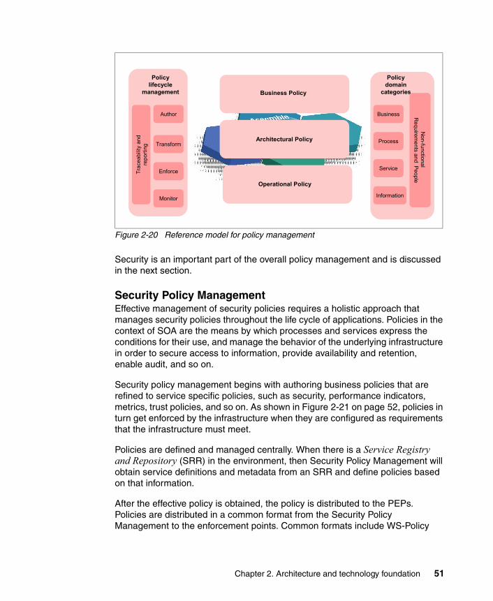
Figure 2-20 Reference model for policy management
Security is an important part of the overall policy management and is discussed in the next section.
Security Policy ManagementEffective management of security policies requires a holistic approach that manages security policies throughout the life cycle of applications. Policies in the context of SOA are the means by which processes and services express the conditions for their use, and manage the behavior of the underlying infrastructure in order to secure access to information, provide availability and retention, enable audit, and so on.
Security policy management begins with authoring business policies that are refined to service specific policies, such as security, performance indicators, metrics, trust policies, and so on. As shown in Figure 2-21 on page 52, policies in turn get enforced by the infrastructure when they are configured as requirements that the infrastructure must meet.
Policies are defined and managed centrally. When there is a Service Registry and Repository (SRR) in the environment, then Security Policy Management will obtain service definitions and metadata from an SRR and define policies based on that information.
After the effective policy is obtained, the policy is distributed to the PEPs. Policies are distributed in a common format from the Security Policy Management to the enforcement points. Common formats include WS-Policy
Operational Policy
Architectural Policy
Business Policy
Author
Policylifecycle
management
Transform
Enforce
Monitor
Business
Policydomain
categories
Process
Service
Information
Non-functional
Requirem
ents and People
Trac
eabi
lity
and
repo
rting
Chapter 2. Architecture and technology foundation 51

and XACML (see Appendix C, “Security terminology, standards, and technology” on page 439).
Figure 2-21 Security Policy Management: Definition and enforcement
Figure 2-22 highlights the Security Policy Management within the IBM SOA Security Reference Model.
Figure 2-22 Components of Security Policy Management
Policy administrationPolicy administration addresses policy life cycle management including creation, maintenance, change, and deletion. This allows business policies to be refined into service specific policies, such as security, performance indicators,
Security Policy Management
Service Registry & Repository(as intermediary for policy exchange, distribution)
Portal
Transform to URL level policies and portlets
Canonical form(e.g WS-Policy)
ApplicationServer
Canonical form(e.g WS-Policy)
Transform to application policies and configuration
Transform to appliance configuration on service
interfaces
Canonical form(e.g WS-Policy)
Metadata &
Services
Publish policies
Policy Administration
Policy Distribution and Transformation
Policy Decision and Enforcement
Monitoring and Reporting
Security Policy Management
52 Understanding SOA Security Design and Implementation

metrics, and trust policies. In turn, they are enforced by the infrastructure when configured as requirements that the infrastructure must meet.
After an application is deployed, application-related policies are administered to reflect changes that occur during the lifetime of the application. Changes to security policies include authorization policy changes (for example, adding new roles that can access the resources), user management changes (for example, users assigned to additional user groups), changes to audit requirements, or constraints, such as integrity or confidentiality.
Underlying the policy management infrastructure is the ability to articulate policies in terms of metadata of the services. Policy metadata may include information about services, identities or other contextual information like strength of encryption.
Policy distribution and transformationCertain requirements or constraints on the access to the service itself (including authentication, integrity, and confidentiality requirements) must be made known to a requesting client runtime. An organization can be capable of providing a range of options to serve a wide variety of client runtimes (for example, browser clients, non-browser clients, and PDA thin clients). In this case, policies can be published that declare the requirement for a requestor runtime to ensure message confidentiality and provide some evidence of the identity of the requesting user.
The security policies that are created need to be distributed to the enforcement and decision points within the infrastructure with the appropriate information (Figure 2-23 on page 54). The policies can be defined centrally and then distributed to the enforcement points in a canonical format, for example, XACML, WS-Policy, or WS-SecurityPolicy. The binding information to enforce the policies is also distributed appropriately. These policies are then transformed at the enforcement point to a local representation so that they can be enforced.
Chapter 2. Architecture and technology foundation 53
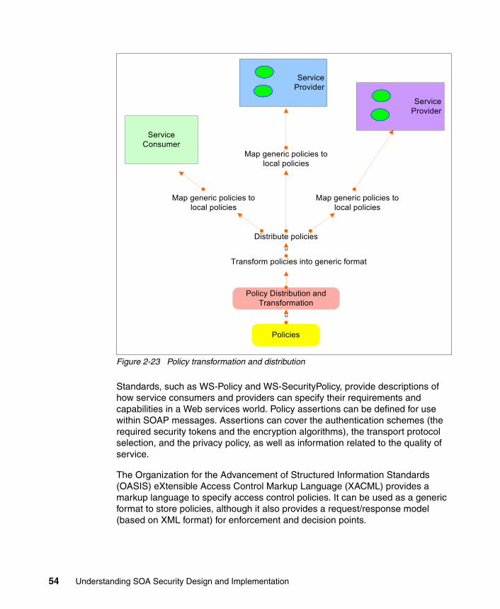
Figure 2-23 Policy transformation and distribution
Standards, such as WS-Policy and WS-SecurityPolicy, provide descriptions of how service consumers and providers can specify their requirements and capabilities in a Web services world. Policy assertions can be defined for use within SOAP messages. Assertions can cover the authentication schemes (the required security tokens and the encryption algorithms), the transport protocol selection, and the privacy policy, as well as information related to the quality of service.
The Organization for the Advancement of Structured Information Standards (OASIS) eXtensible Access Control Markup Language (XACML) provides a markup language to specify access control policies. It can be used as a generic format to store policies, although it also provides a request/response model (based on XML format) for enforcement and decision points.
ServiceProvider
ServiceConsumer
c
Distribute policies
Policy Distribution and Transformation
Transform policies into generic format
Map generic policies to local policies
Map generic policies to local policies
Map generic policies to local policies
ServiceProvider
Policies
c
54 Understanding SOA Security Design and Implementation

There can also be a policy that controls the transformation and distribution of the policies.
Policy decision and enforcementAccess to a resource is controlled by an appropriate resource manager, which is the logical policy enforcement point (PEP) corresponding to that resource. Administrators will update security policies through the resource managers or administer policies through appropriate policy decision points (PDPs). In a typical deployment, you can find several enforcement points. Each of these enforcement points can have its own mechanisms to enforce security for the incoming requests.
The enforcements points rely on PDPs to make decisions. These PDPs contain the security policies defined in the infrastructure. The requirements and thus the policies are different, depending on the security domains and the application platforms.
One challenge of having multiple PEPs and PDPs in the infrastructure is that they are often administered by different entities. Providing integrated and centralized decision capabilities reduces the administrative tasks related to policy management.
Monitoring and reportingClosely linked to the decision and enforcement of these policies is the infrastructure to help monitor the behavior of system elements throughout the life cycle of the business. When managing security policies, it is necessary to adhere to changing corporate business security policies, as well as industry and government regulations, and compliance requirements. In addition to these reasons to change, another input factor is the discovery of vulnerabilities and new risks that might be identified through solution monitoring activities.
It is necessary to keep track of current policies, historic policies, and the assessment of compliance of lower level policies against corporate policies. Traceability of policies from high level business policies to enforced configurations and runtime requirements is necessary to verify on what the runtime behavior is based. This helps identify policy changes that occur and can help manage accountability of policy changes. Security policies need to be developed and deployed throughout the stages of the life cycle of an application.
Note: More detailed information about the standards is available in Appendix C, “Security terminology, standards, and technology” on page 439.
Chapter 2. Architecture and technology foundation 55

Changes to security policies must be tightly controlled, access to them must be traced, and audit trails must be supplied so that the processes can be adequately monitored.
2.2.5 Governance and Risk Management
Governance of SOA Security is a subset of the overall SOA Governance function. Governance is very important for the security services, because managing the security policy and implementation is vital to the integrity of the environment.
A framework for the effective governance structure and decision making authority is needed in order to run the business. Tools and technologies can help facilitate governance initiatives and compliance evaluations. An effective security governance framework involves establishing chains of responsibility, authority, and communication to empower people to effectively control the system.
Because SOA extends interactions beyond the enterprise boundary, the governance of SOA Security must interact with similar groups in other organizations to achieve a common set of standards for communication across the enterprise boundary.
Risk management deals with the process of evaluating and assessing risk in the SOA environment and developing strategies to manage those risks. Risk management balances risks with the cost of managing those risks. The risk management process determines how to manage risk based on factors, such as probability and impact. While software tools can help implement a risk management process, people and processes are the main components.
Business processes and policies are needed for defining organizational roles and responsibilities for process and authority. Risk management processes and policies are needed to evaluate strategies for managing risk. Compliance can include assessment processes and reporting policies, for example, what type of assessment is used, how often it is executed, and who must be informed.
2.3 IBM SOA Security Reference Model
The IBM SOA Security Reference Model11 (Figure 2-24 on page 57) is derived from the list of capabilities previously discussed. A reference model can help to address requirements and lead to a logical architecture, then to a physical
11 Based on feedback from a number of sources, this is the second release of the reference model devised by the Software Group Architecture Workgroup on SOA Security.
56 Understanding SOA Security Design and Implementation

architecture, with products and technologies mapped to solve the current problem.
SOA security is applicable to all layers of an SOA model: across infrastructure, application, business services, and development services. It is applicable in serving the needs of a service consumer. Based on the capabilities discussed in the previous sections, the reference model can be viewed in terms of three layers of abstraction: Business Security Services, IT Security Services, and Security Policy Management. There are also Security Enablers for providing security functions to the IT Security Services.
Figure 2-24 IBM SOA Security Reference Model
At a very high level, we can define the following main areas in the model:
� Business Security Services involve managing the needs and requirements of the business, such as trust, identity and access management, data protection, compliance and reporting, non-repudiation, and secure systems and networks. They build on the common policy infrastructure to effectively manage the relevant policies applicable to meet the business needs.
� IT Security Services describe the foundation blocks for an SOA infrastructure, providing the ability to secure the services and meet the needs of applications
Go v
erna
nce
and
Ris
k M
ana g
emen
t
P olic
y M
a nag
eme n
t
S ecu
rity
P olic
y M
anag
eme n
t
IT Security Services
IdentityServices
Confidentiality Services Integrity Services
Authentication Services Authorization Services
Audit Services
Business Security Services
Compliance and Reporting
Identity and Access Trust Management
Data Protection, Privacy and Disclosure
Control
Non-repudiation Services
Security Enablers
Secure Systems and Networks
Chapter 2. Architecture and technology foundation 57

and infrastructure by rendering security functionality as services themselves. These services include identity, authentication and authorization, as well as confidentiality, integrity, and Audit Services.
� Security Enablers include technologies, such as cryptography, directories, and key stores that are utilized by the IT Security Services to perform their tasks.
� Security Policy Management is a part of the overall Policy Management and entails articulating, managing, enforcing, and monitoring security policies. This includes the ability to define policies to authenticate and authorize requesters to access services, propagate security context across service requests based on an underlying trust model, audit events of significance, and protect information. All of these are done based on a policy-based infrastructure. Thus, Security Policy Management functionality is a core part of providing security capability in SOA.
� Governance and Risk Management provide the mechanism to implement and enforce security policies within the larger SOA environment. Governance helps clients manage SOA across the organization. Risk management deals with the process of evaluating and assessing risk in the SOA environment and developing strategies to manage those risks.
Within the broader context of the IBM SOA Reference Model, the IBM SOA Security Reference Model is a sub-component of the IT Service Management pillar as depicted in Figure 2-25 on page 59. More details about the bigger IBM SOA Reference Model can be found in Appendix B, “IBM SOA Foundation” on page 415, especially in Figure B-3 on page 421 Figure B-3 on page 421.
58 Understanding SOA Security Design and Implementation

Figure 2-25 IBM SOA Reference Model: Security capability within IT Service Management
2.4 Architecture decision guide
Having decided on a model, the next step is to derive an architecture and design with real products. Design is more context specific and dependent than architecture. While there is no substitute for an experienced practitioner, a set of questions have been formulated to help identify the correct capabilities, design, and technology/product selection:
� Are there applications or business services that need to be secured (do they provide access to confidential information)?Emphasizing SOA principles, plan to externalize security enforcement out of application logic whenever possible and let it be handled by the infrastructure (which provides the common security services). Infrastructure that handles security can be a combination of middleware and intermediaries.
IT S
ervi
ce
Man
agem
ent
Monitor, manage
and secure services,
applications &
resources
Gov
erna
n ce
a nd
Ris
k M
anag
e men
t
Polic
y M
anag
eme n
t
Secu
rity
P olic
y M
anag
emen
t
IT Security Services
Business Security Services
Security Enablers
Chapter 2. Architecture and technology foundation 59

Authentication, authorization, message, and transport security functionality can be provided by the middleware application environment when appropriate, but when security policies are enforced through intermediaries, such as Web services gateways and Web proxies, it is possible to create reusable security assets to achieve the enterprise’s overall SOA goals.
Centrally managing security policies is a good practice across applications, middleware and intermediaries.
� Are these services accessible from outside the enterprise environment? Are there different security requirements for different access paths?Use a defense in-depth approach by enforcing security policies at intermediaries, middleware, and applications consistently throughout the organization to ensure messages are appropriately protected for integrity and confidentiality.
Intermediaries can be deployed at a perimeter, such as the organizational perimeter or enterprise perimeter. For example:
– Use Web services gateways at the perimeter to handle XML security (to enforce perimeter level security for authentication, authorization, or XML screening)
– Use Web proxies at the perimeter to handle HTTP/S security (to enforce authentication, authorization, or HTTP content)
– Use middleware, including application servers, transaction servers, and enterprise service buses, to enforce security controls
� Do service requests cross security domains of the enterprise? Do policies need to be managed across security domains?Use a combination of Web services gateways for XML messages and Web proxies for Web applications at any security domain boundary to provide identity and authorization transforms of message content/headers. Trust policies relevant to each domain and organizational boundary transitions can then be enforced consistently.
These enforcement points can also be used in combination with identity propagation services to specifically manage identity trust policies and credential transformations.
� Is the aim to achieve single sign-on for your users accessing services, including from .NET client desktops?
Based on the method by which services are accessed, an appropriate single sign-on (SSO) approach applies:
– Web SSO: For SSO for Web application requests over HTTP protocol, use a Web proxy deployed in front of a variety of Web application servers and
60 Understanding SOA Security Design and Implementation

application platforms. This includes support for .NET client desktops using SPNEGO technology protocol.
– Federated SSO: For requests crossing enterprise and security boundaries across heterogeneous platforms, and trust domains, use intermediaries, such as Web services gateways to act as the point of contact for SOAP requests and Web proxy capability for HTTP requests. Use a federated identity management solution to manage the federation policies, identity mapping, and trust policies.
– Backend SSO: In order to map identities and credentials and connect to backend systems from your business logic, use a security token service. Have a portal or application server call the security token service. If the backend access can be routed through an intermediary, use a Web services gateway to handle the enforcement.
– End client SSO: There are applications that are accessed using a variety of clients and protocols where SSO has to be done closer to the user (than at the enterprise boundary). In these cases, use a client application single sign-on implementation where client credential store is used to store the user’s credentials (user ID and password) and to automatically let the user log on to applications.
� Are business partners allowed to access services from business partners using identities defined in their organization?Federated identity management allows the management of trust policies and federated identities across the enterprise boundaries. Web services gateways can act as the intermediary to enforce the federation. Identity information can include identifiers and attributes, such as roles and groups.
� Are there composite services where a service can access other services for completing its task? When there is a chain of service invocations, it might be necessary to encapsulate messages and their headers to provide a chain of identity so that the Web services gateway or enterprise service bus can provide some message augmentation to include headers indicating what other entities have touched a message on its route to the end application.
Define and manage service and subscriber identities, and manage them using an identity management capability as part of the business and IT processes.
� Is the auditing of access to services required for meeting compliance goals?For compliance reasons, it might be required to create audit records from a number of points within an infrastructure. This includes archiving, analysis, and reporting. These records can be from a variety of middleware and appliances that enforce security for service requests and for other business
Chapter 2. Architecture and technology foundation 61

events that can occur in services. It is possible to address compliance goals in every part of the application life cycle using relevant tools, such as requirements capture and development tools to define application level declarative security policies.
� Are there services accessing applications hosted on z/OS® platforms?Web services gateways can be placed in front of mainframe applications hosting Web services to secure message exchanges. You can connect from a Web application server using Java™ connectors.
In either of these connection modes, you can use identity propagation capabilities to manage trust relationships and identity mappings and help transform identities from a distributed environment to the z/OS platforms.
� Are services part of a business process? Is subscription management to services required? Use the identity management capability to provision identities for users and services, and manage entitlements of those users to services as part of the enterprise identity management policies and workflows.
� Is there a requirement to efficiently enable partners and vendors to federate access to services?
Use federated identity management capabilities in the enterprise. Partners can use business gateway federation capabilities to rapidly federate into the environment.
2.5 IBM products and services
To complete this chapter, this section outlines the IBM products that map onto the IBM SOA Security Reference Model (see Figure 2-26 on page 63). Based on the decisions in the previous section, it is possible to select one or more of the IBM products to meet the security requirements identified. More information is provided in the rest of this IBM Redbooks deliverable.
62 Understanding SOA Security Design and Implementation

Figure 2-26 IBM SOA Security Reference Model: IBM Product Mappings
2.6 Summary
By examining a number of SOA security use cases and analyzing some of the challenges and their solutions, the IBM SOA Security Reference Model has been derived. The main features of the model are:
� Business Security Services, which describe security from a business point of view.
� IT Security Services, which provide a common set of services for use by different components in the environment.
� Security Policy Management, outlining the important aspects around the life cycle and implementation of security policy.
� Security Enablers, providing the supporting security technology and function for use by the IT Security Services.
The chapter closes with architectural decisions to help an IT architect derive a logical/physical architecture from the IBM SOA Security Reference Model. We
Go v
erna
nce
and
Ris
k M
ana g
emen
t
Polic
y M
anag
emen
t
S ecu
rity
Poli c
y M
ana g
emen
t
IT Security Services
Identity Services
Confidentiality Services Integrity Services
Authentication Services Authorization Services
Audit Services
Business Security Services
Compliance and Reporting
Identity and Access Trust Management
Data Protection, Privacy and Disclosure
Control
Non-repudiation Services
Security Enablers
Secure Systems and Networks
Tivoli Federated Identity Manager
Tivoli Identity Manager
Tivoli DirectoryIntegrator
WebSphereDataPower
Tivoli AccessManager
WebSphereDataPower
WebSphereDataPower
Tivoli DirectoryServer
Tivoli Security Operations Manager
Tivoli Compliance Insight Manager
WebSphereDataPower
Tivoli AccessManager
Tivoli zSecure
Tivoli SecurityCompliance
ManagerISS ProventiaNetwork MFS
ISS Proventia Nework IPS
Glo
bal B
usin
es S
ervi
ces
& G
loba
l Tec
hnol
ogy
Serv
ices
WebSphereApplication Server
WebSphereApplication Server
WebSphereApplication Server
WebSphereApplication Server
ISS ProventiaServer
Chapter 2. Architecture and technology foundation 63

conclude with a mapping from the IBM SOA Security Reference Model to IBM products and services, showing how the model can be addressed for client environments.
64 Understanding SOA Security Design and Implementation

Part 2 IBM SOA Foundation scenarios
IBM SOA Foundation scenarios are a group of reusable assets that can help speed the process of developing SOA-based applications. This part describes four of the IBM SOA Foundation scenarios and the security issues involved.
The scenarios need to be read in the order they are presented. The security described for each scenario builds on that described for the previous scenario. That is, begin reading at the Service Creation scenario, read the Service Connectivity scenario next, then the Interaction and Collaboration Services scenario, and finally read the Business Process Management scenario.
Part 2
© Copyright IBM Corp. 2007. All rights reserved. 65

66 Understanding SOA Security Design and Implementation
Chapter 3. IBM SOA Foundation Service Creation scenario
In this chapter, we describe the application of the IBM SOA Security Reference Model, as defined in Chapter 2, “Architecture and technology foundation” on page 17, to the Service Creation scenario.
This scenario is the first of the IBM SOA Foundation scenarios (see Appendix B, “IBM SOA Foundation” on page 415) and highlights the creation of services from an existing application. This is a very common SOA scenario with businesses aiming to leverage their existing applications and data more effectively, providing access to new service consumers.
In this chapter, we examine the Service Creation scenario in some detail by showing the security implications of exposing the existing application in this way. There are many new security issues to deal with, because the existing application is exposed to new service consumers.
3
© Copyright IBM Corp. 2007. All rights reserved. 67

3.1 Scenario overview
This section contains a brief description of the SOA Foundation Service Creation scenario.
The Service Creation scenario describes how to expose existing application functionality and new business logic as services. These services can then be consumed by other services or client applications within an enterprise and between enterprises.
An example of the Service Creation scenario is given in Section 1.1.1, “Service creation at an insurance company” on page 4. In this example, the insurance company wants to expose its existing insurance application as a service to enable the faster creation of new insurance products and access through new channels.
By exposing the application functionality as a service, client applications, which are internal and external to the enterprise, can consume these services. This SOA approach simplifies the integration challenges and leverages the business value of existing systems.
3.1.1 Direct exposure architectural pattern
There are two main architectural patterns to illustrate the Service Creation scenario. Figure 3-1 on page 69 shows one pattern where the existing Enterprise Information System (EIS) applications are directly exposed as services. In this architectural pattern, the service interface is defined largely by the existing application. An example of an EIS is CICS Transaction Services (TS) 3.1, which has the capability to expose its applications directly as Web services.
68 Understanding SOA Security Design and Implementation

Figure 3-1 Directly exposing existing applications as services
As shown in Figure 3-1, multiple service consumers can invoke the services exposed from the existing application. The benefits of this approach include a shorter deployment cycle through the reuse of the existing assets.
There can be multiple types of service consumers:
� User access via a portal: The user interacts with the portal from a browser. The portal generates service requests to the EIS on behalf of the user. An example of a portal is WebSphere Portal.
� Internal service consumer: An application generates service requests to the EIS. This might be from a user with a rich client application or from another application within the environment that is not directly user driven. One example is an application hosted on WebSphere Application Server.
� External service consumer: The difference from the internal case is that these service requests are from outside of the domain of the EIS. For example, the requests are from another organization or another business unit of the same organization. The dashed line indicates the requests are coming from a foreign domain. One example is a rich application hosted on a Microsoft ASP.NET application server accessing from a partner organization.
CICS TS 3.1
WebSphere Application
Server
Microsoft .NET Application
Server
WebSphere Portal Enterprise Information System
Internal Consumer
External Consumer
Chapter 3. IBM SOA Foundation Service Creation scenario 69

3.1.2 Indirect exposure architectural pattern
The indirect exposure pattern is shown in Figure 3-2. This illustrates how to indirectly expose the existing EIS applications using service components. In this architectural pattern, a middle tier is used to create services from the EIS application. A middle tier might be required when additional business logic is needed to bridge the interface between consumers and the set of directly exposed services. This middle tier is also known as an intermediary.
Figure 3-2 Indirectly exposing existing applications via service components
An example of an EIS is CICS Transaction Server (TS) 2.2 whose services are exposed using WebSphere Application Server and the CICS Transaction Gateway (CTG). An example of a portal is WebSphere Portal, with its portlets generating service requests. Examples of internal and external service consumer applications are WebSphere Application Server-hosted and Microsoft .NET-hosted applications respectively.
3.1.3 Security requirements
The existing application was developed with assumptions and constraints in mind. Now, additional requirements emerge due to the architecture patterns described in the previous section.
For example, EIS systems are accessed directly by the user via a terminal or similar application. As shown in Figure 3-3 on page 71, a CICS application is
WebSphereApplication
Server
WebSphere J2EE Application
Microsoft .NET Application
CICS Transaction
Gateway
WebSphere Portal
CICS TS 2.2
Enterprise Information System
Internal Consumer
External Consumer
70 Understanding SOA Security Design and Implementation

typically accessed via a 3270 terminal program. The user has a direct connection from their terminal application to the EIS and authenticates with user name and password. The communication can be protected by Secure Sockets Layer (SSL).
Figure 3-3 Accessing the EIS directly
When an existing application is re-purposed, the original assumptions might no longer be true. Hence, additional measures need to be taken to safeguard the information and protect the application:
� The application might have been developed for internal use only, but with exposure as a Web service and access from multiple channels, there are no longer tight controls about where and how this information is being used. There might be a requirement to provide adequate measures to protect the information both in transit and at rest. Depending upon how and where this information is being accessed, either message level or transport level security can be applied.
� The security system protecting the original application is often different from the techniques used to protect intermediaries. For example, the EIS system can be protected by RACF while the intermediary, such as WebSphere Application Server, can use a Lightweight Directory Access Protocol (LDAP) directory. In these cases, there needs to be a mapping of security context and secure propagation of that context so that appropriate security controls are applied.
We might also need to manage the same user identity between multiple identity stores (RACF, LDAP, Microsoft Active Directory, and so on). This is required for the life cycle of the user. An identity provisioning solution is required.
� In the original architecture, auditing might have taken place only on the EIS. Every action taken by the user has been audited using the user’s identity. The new architecture might have the requirement to audit information at multiple places for compliance reasons and drive the need for additional reports. For example, auditing along the entire request chain rather than just at the EIS might be required.
� There is a requirement for multiple authorization checks, because the existing application might not know the context under which the information will be
CICS TS 2.2
Enterprise Information System
TerminalApplication SSL
username/password
Chapter 3. IBM SOA Foundation Service Creation scenario 71

used. It is necessary to provide additional authorization capabilities at the services intermediary.
� It is necessary to provide the user with a seamless experience even when introducing intermediaries. For example, the user does not need to input authentication details for the EIS if they are already authenticated at the service consumer. This requires that trust relationships are established along the request chain so that identity can be propagated.
3.2 Applying the IBM SOA Security Reference Model
This section discusses how to apply the IBM SOA Security Reference Model to the Service Creation scenario. The decision about which components should be applied for a particular implementation of the Service Creation scenario depends on the relevant business requirements. For example, in some cases the services have high security requirements, such as in the banking or insurance industries. In other cases, the services have lower security requirements, such as public information sources. An IT architect must therefore decide which of the IBM SOA Security Reference Model components should be applied for their particular implementation based on the business requirements.
3.2.1 Business Security Services
The following Business Security Services define what the business requires when opening up their application functionality through the Service Creation scenario.
Compliance and ReportingBecause the original assumption of a closed environment no longer holds, the business needs to be sure that they are still compliant with regulation and business policy.
For example, the organization might need to implement a process to gather audit events from various points along the request path. These events are then available for compliance reporting.
The business has to provide new reports to meet compliance requirements, such as the Sarbanes-Oxley Act (SOX) or Payment Card Industry Data Security Standard (PCI).
72 Understanding SOA Security Design and Implementation

Data Protection, Privacy, and Disclosure ControlThe business needs to provide the classification of data being exposed in the Service Creation scenario. For example, parts of the data might be very sensitive for privacy or other business reasons and must be protected.
It can therefore become a business requirement to protect data in transit from unauthorized disclosure. Data then passes through the service intermediary and over untrusted networks. The business might need to have the data protected throughout the entire request path.
Non-repudiation ServicesThe business requirements around non-repudiation must be defined. The business should list which transactions fall into this category. For example, the business might require all transactions of a particular type to have non-repudiation protection. The business might be satisfied with log file entries of events to be used as non-repudiation evidence. Alternatively, the business might require stronger mechanisms, such as digital signatures.
Identity and AccessThe business needs to define the requirements around user life cycle management. For example, the business might prefer a policy-based approach to controlling user identity and access, especially since the business is no longer working under a closed access model.
The definition of the authorization policy is the key input from the business. For example, the business can define that only certain partners can get access to information and possibly only under specific conditions.
Trust ManagementWhen exposing the existing application, the business must define which external parties are to be partners. For example, a set of partners for an insurance company might be able to access services for new insurance applications. The business needs to define the specifics of the relationship, such as information that has to be exchanged in order to establish trust, and define the length and extent of the relationship.
Secure Systems and NetworksThe business defines the requirements around secure networks. If the data is sensitive, the business can mandate that strong secure network technology is in place before the existing application can be opened up for access. For example, the business can mandate end-to-end protection of messages and a secure Internet-facing network infrastructure, such as an IPsec virtual private network (VPN).
Chapter 3. IBM SOA Foundation Service Creation scenario 73

3.2.2 IT Security Services
IT Security Services can be used by different components in an SOA environment, such as gateways, proxy servers, application servers, data servers, and operating systems. The use of common IT Security Services enables a consistent security implementation. It also minimizes development and deployment costs for implementing these services.
Identity ServicesIn SOA, the most fundamental security issue to deal with is often related to the identity services. Figure 3-4 shows the direct access by the user (Joe Smith) to the EIS before service creation. Users accessing the EIS are defined in the EIS’ user repository. There can be other user repositories in the enterprise but the important point demonstrated in the figure is that Joe Smith logs in to the EIS RACF with his own user name and password, and actions are authorized and audited under that identity.
Figure 3-4 Direct access by Joe Smith to the EIS
In the Service Creation scenario, there are multiple new user repositories introduced into the transaction path. This creates complexity around managing, propagating, and mapping the identities.
Identity FoundationAs shown in Figure 3-5 on page 75, there are different user repositories storing Joe Smith’s identity information in the Service Creation scenario. In each repository, he is known with a different identifier: EIS (joey1234), portal (joe), internal consumer (jsmith), and external consumer (homejoe). Another identity for the user is stored in an enterprise user repository storing common identity information for the enterprise (joesmith). In Figure 3-5 on page 75, Tivoli Directory Server is being used for the portal user repository and RACF for the EIS user repository.
CICS TS 2.2
Enterprise Information System
TerminalApplication SSL
Username joey1234Password ########
joey1234
RACF
74 Understanding SOA Security Design and Implementation

Figure 3-5 Identity foundation for the Service Creation scenario
Each of these repositories has different identity and attributes for Joe Smith. Some of these attributes will be common between the repositories, and a change in one repository must be updated in the others. For example, the user might update their address in the portal user repository, and this change needs to be propagated to the EIS user repository.
User repository synchronization technology is often used to do this. When a change in one repository is detected, other user repositories that need to be synchronized are updated. This is shown in Figure 3-5 with a synchronization connection between the EIS RACF and portal user repositories using Tivoli Directory Integrator to perform the synchronization.
Identity provisioningIn order to manage the identities and attributes in each user repository effectively, an identity provisioning solution is required, as shown in Figure 3-6 on page 77. Although identity provisioning technology might have already been deployed before service creation, the Service Creation scenario with the
CICS TS 3.1
WebSphere J2EE Application
Microsoft .NET applicationhomejoe
joesmith
joey1234jsmith
joe
WebSphere Portal
Tivoli DirectoryIntegrator
Tivoli Directory
Server
RACF
EnterpriseUser Repository
Chapter 3. IBM SOA Foundation Service Creation scenario 75

additional user repositories along the transaction path increases the requirement for automated provisioning of identity data.
There is an additional requirement in that the user might not be aware of their EIS account any longer under the Service Creation scenario. In the direct access case, the user knew their RACF user name and password and updated their password when required (for example, 30 days is common). However, it is more than likely that the users no longer interact directly with the EIS and RACF. Instead, an automated provisioning solution needs to manage the user accounts, including their password.
The identity provisioning solution can create, modify, and delete individual account information across all of the user repositories. The advantage of this approach is that a policy-based provisioning solution allows only the correct identity and attribute information in each of the repositories. This policy can be configured centrally, and changes are driven from this central location. In Figure 3-6 on page 77, Tivoli Identity Manager is used for the automated provisioning, and this technology ensures that the user’s identity information is kept current throughout the user’s life cycle.
76 Understanding SOA Security Design and Implementation

Figure 3-6 Identity provisioning for the Service Creation scenario
One special case of provisioning in the Service Creation scenario is how to provision the external consumer user repository with user identity homejoe. This approach is termed federated provisioning, because provisioning is occurring to another administrative domain. In this case, federated provisioning standards, such as SPML and WS-Provisioning, can be used to enable interoperability between different technologies (see Appendix C, “Security terminology, standards, and technology” on page 439).
An identity provisioning solution can also provide user self-service and password synchronization capabilities. For example, the provisioning solution might allow a user to self-enroll with a service through a portal and update their own information and password, all without requiring intervention from an IT administrator.
CICS TS 3.1WebSphere J2EE
Application
Microsoft .NET applicationhomejoe
joesmith
joey1234jsmith
joe
IdentityProvisioning
WebSphere Portal
Tivoli IdentityManager
RACF
Tivoli Directory
Server
Enterprise User Repository
Chapter 3. IBM SOA Foundation Service Creation scenario 77

Identity propagationAs part of the transaction flow in the Service Creation scenario, trusted identity information is required to flow through the environment, as shown in Figure 3-7. Identity information might need to be received and interpreted within a different domain of trust:
� The format of the identity might need to be transformed. For example, a Java Subject in WebSphere Portal is transformed into a RACF user ID and passticket for the EIS.
� A different identity representing the user might be required. This is the case when the user account used to log on to the portal user repository (Tivoli Directory Server) is different than the user account on the EIS (RACF). Hence, mapping of identities is required.
One way to solve this is to use a security token service as shown in Figure 3-7 to bridge the identity between two domains. The role of the security token service is to perform the identity format translation and the identity mapping.
Figure 3-7 Identity propagation in the Service Creation scenario
In Figure 3-7, the request from WebSphere Application Server is required to carry a RACF user ID and passticket. Before sending the request to CICS, the authenticated identity from WebSphere Application Server needs to be mapped and transformed. This can be achieved with a security token service that maps the incoming user name of jsmith to a RACF user ID of joey1234. The security
CICS TS 3.1 joey1234
Security Token Service
Inbound request (security token)
User=jsmith
Outbound request (security token)
User=joey1234
WebSphere J2EE Application
jsmith
Tivoli FederatedIdentity Manager
RACF
Domain A
Domain B
78 Understanding SOA Security Design and Implementation

token service also generates a RACF passticket for the user. In Figure 3-7 on page 78, the Tivoli Federated Identity Manager Security Token Service is used for this purpose.
Authentication ServicesFigure 3-8 shows an example of CICS where a service is exposed using the direct exposure pattern. Incoming messages contain authentication credentials in a suitable form for direct passing to the authentication service. In this example, RACF is the authentication service, and it is able to validate user ID/password and user ID/passticket credentials. The System Authorization Facility (SAF) is the interface that CICS uses to access the authentication service. More information about the System Authorization Facility can be found in “System Authorization Facility” on page 456.
Figure 3-8 Authentication example when using the direct exposure pattern
In the indirect exposure case, an Authentication Service is required at the intermediary to authenticate the credentials supplied by the service consumer (Figure 3-9 on page 80). In addition, these credentials can be in a different format from the credentials that the back end expects and contain representations of identity from a different administrative domain. This can be resolved by the Tivoli Federated Identity Manager (TFIM) Security Token Service.
Important: In this example, the security token service is providing a one-to-one mapping between service consumer identity and service provider identity. In some cases, the back-end system does not require the user’s real identity for authorization and audit purposes. Instead, the identity can be translated to a system identity (for example, the billing application) or an identity representing a role (for example, managers from western region or all IBM employees).
CICS TS 3.1
joey1234
Authentication Service
RACF
Chapter 3. IBM SOA Foundation Service Creation scenario 79

Figure 3-9 Authentication example when using the indirect exposure pattern.
For example, Web services requests containing WS-Security headers can be processed at WebSphere Application Server. Different security tokens can be validated in different ways. For example, Federated Identity Manager provides a plug-in for the Web services security processing in WebSphere Application Server so that security tokens can be validated and exchanged using the Federated Identity Manager STS. Use of the external authentication service provided by the Federated Identity Manager STS provides flexibility in catering to a variety of token types and centralizes the logic around security token processing in a single service.
Authentication Services together with identity propagation described in the previous section provide solution components that enable end-to-end identity flow, one of the most significant security challenges in SOA.
Authorization ServicesFigure 3-10 on page 81 shows the application of the Authorization Services for the Service Creation scenario. In the case of direct access to the EIS, authorization was only a concern for the EIS, and this can be implemented by RACF. In the Service Creation scenario, authorization is required along the request chain. Authorization is shown at four points in Figure 3-10 on page 81:
� Service consumer: For the portal and J2EE (internal) consumers, authorization can be implemented to control what the user can see and do. The authorization might be exposed to the Authorization Service for these
CICS TS 3.1
joey1234
Authentication Service
RACF
Authentication Service
WebSphere Application
Server
TFIM
80 Understanding SOA Security Design and Implementation

consumers or might be implemented internally within the consumers. For example, WebSphere Portal provides its own authorization model that can be used without any external authorization provider.
For the portal and J2EE application, authorization can be role-based. In the J2EE security model, the authorization decision is based on which roles can access the resource and can the user invoke any of these roles. It is common to externalize the authorization decision to an authorization service. In the example, the J2EE application authorization is externalized to Tivoli Access Manager for e-business, and for the portal authorization, the WebSphere Portal authorization model is used.
� Service provider: The authorization at the service provider is coarse-grained and is concerned with service level authorization. That is, can the user access the operation on the service they are trying to access? The service level authorization can be externalized to the Authorization Service or can be internal to the service provider interface. In the example, the Authorization Service is implemented using Tivoli Access Manager for e-business.
� Application: This was required for direct access to the EIS. There can be authorization at the application level controlling what the user is able to do. The authorization can be externalized or internal to the application. For example, in a CICS-based application, authorization rules can be set up against an external authorization service, such as RACF.
� Data: This was already required for direct access to the EIS. There can be further authorization required at the data level, but in most cases, it is configured at the database level. In the example, RACF authorization is used.
Figure 3-10 Authorization Services for the Service Creation scenario
WebSphere J2EE Application
Microsoft .NET application
Data
WebSphere Portal
Authorization Service
Authorization Service
RACFTivoli Access Manager for e-business
WebSpherePortal
Security
WebSphereApplication
Server
CICS Transaction
Gateway
CICS TS 2.2
Authorization Service
Tivoli Access Manager for e-business
Chapter 3. IBM SOA Foundation Service Creation scenario 81

The emerging standard that can be leveraged to consolidate authorization management and enforcement is eXtensible Access Control Markup Language (XACML).
Confidentiality ServicesWhen directly connecting to the EIS, the user’s terminal program can create an SSL connection to provide the confidentiality of the data that is sent over the connection. The Service Creation scenario adds many more network links between the user and EIS and these network links need to be protected.
Figure 3-11 shows the application of the Confidentiality Services for the indirect architectural pattern of the Service Creation scenario.
Protecting message content from being disclosed is the primary concern of this service. This is usually achieved by encrypting the message body, header, or any combination of these parts. In the diagram, both SSL and WS-Security are used to protect data in transit. The decision whether to use SSL, WS-Security, or both depends on the business drivers and the information that is being protected. The implementation is through WebSphere Application Server, Microsoft ASP.NET Application Server, and CICS TG.
In Figure 3-11, CICS application data is protected using DB2 encryption capabilities. Data protection in reality will be required wherever there is sensitive data, including passwords, cryptographic keys, configuration files, and so on.
Figure 3-11 Confidentiality Services for the Service Creation scenario
WebSphere J2EE Application
Microsoft .NET application
Data
WebSphere Portal
WebSphereApplication
Server
CICS Transaction
Gateway
CICS TS 2.2
WS-Security
SSL
WS-Security
WS-Security
SSL
DB2 Encryption
WebSphereApplication
Server
WebSphereApplication
ServerCICS TG
WebSphereApplication
Server
Microsoft ASP.NET
82 Understanding SOA Security Design and Implementation

Integrity ServicesProtecting message content from being modified without detection, being sure of its origin, and protection against message replays are the primary concerns of this service. This is usually achieved by digitally signing the message body, header elements, such as a security token, or any combination of these parts in a WS-Security message.
Many security tokens defined in WS-Security have the ability to include a data element, such as a nonce to prevent reuse of a security token, to protect against exploits that reuse a security token.
Audit ServicesThe Audit Services are in place to understand the operation of the security environment by collecting audit information and reporting on this information.
When the user is directly connecting to the EIS, then all information is collected at the EIS. For example, RACF and application specific logs might be created.
In the case of the Service Creation scenario as shown in Figure 3-12 on page 84, audit logs are collected along the request path, at all points that are necessary. These can be processed and stored in a format ready for reporting. In the figure, Tivoli Compliance Insight Manager is used to collate, process, and report on the audit data.
Chapter 3. IBM SOA Foundation Service Creation scenario 83

Figure 3-12 Auditing Services for Service Creation scenario
3.2.3 Security Enablers
Typical Security Enablers in the Service Creation scenario include:
� Cryptography: Signing and encrypting libraries, such as XML Signature and XML Encryption, enable higher-level message protection services as found in a WS-Security runtime.
� Intrusion protection: An ISS Proventia® Server can be deployed on the WebSphere Application Server to protect the server from malware and intrusion.
� Directory: As discussed, Tivoli Directory Server is used as the directory for the intermediary that exposes the service.
� Firewalls: Firewalls provide network isolation of the EIS and limit the traffic (origins and protocols) that are permitted to access the EIS. Firewalls can also be used around the intermediary that exposes the service itself.
3.2.4 Security Policy Management
Security Policy Management bridges business and IT Security Services by providing infrastructure for creating business policies and distributing them to IT Security Services.
WebSphere J2EE Application
Microsoft .NET application
AuditData
WebSphere Portal
WebSphereApplication
Server
CICS Transaction
Gateway
CICS TS 2.2
Tivoli Compliance Insight Manager
AuditData
AuditData
AuditData
84 Understanding SOA Security Design and Implementation

Before this scenario, the EIS was managed with a set of security policies sufficient for it being accessed directly. When the application is exposed as a service, security policies are also required at the intermediary. Security policies, such as authentication, authorization, message protection, and audit need to be consistent between the intermediary and the EIS to ensure that the new routes to the application are as secure as the original access method.
Before an application is exposed as a service, the application might or might not already be managed by a central security policy system. In the case that the application is already being managed by a central policy management system, the new intermediary needs to be created as a new target whose security policy is to be managed. Then, existing security policies defined at the business level will be distributed to the intermediary and transformed into a resource-specific security policy that can be enforced.
One example is to create the policies to enforce message level security from the consumer to the intermediary and rely on transport level security from the intermediary to the existing application (EIS). In this scenario, appropriate message protection policies need to be created/authored along with the binding information for which cryptographic key to use, and so on. One way of creating these policies in a canonical form is using WS-Policy. These policies along with the binding metadata then need to be published so that the requestor, the intermediary, and the service provider (EIS) are made aware of this. One example of publishing these policies is through a service registry, such as WebSphere Service Registry and Repository (WSRR), as shown in Figure 3-13 on page 86.
Based on this, the consumer gets an enhanced description of the Web service with WS-Policy data embedded in it, which articulates that WS-Security is required to invoke the Web services provider. Similarly, the intermediary will leverage the policies to validate WS-Security from the requestor and establish SSL with the service provider. Other types of security policies, such as authentication and authorization policies, also need to be authored and published to be enforced by different intermediaries.
Chapter 3. IBM SOA Foundation Service Creation scenario 85

Figure 3-13 Security Policy Management using a service registry
3.2.5 Governance and Risk Management
The SOA governance board is responsible for defining the procedures and policies around change management in the SOA environment in order to manage risk. This includes change control around security policy and the IT Security Service infrastructure.
3.2.6 Summary
The application of the IBM SOA Security Reference Model to the SOA Foundation Service Creation scenario has been described in this chapter. There are many security issues with which to contend, and these issues must be applied across the components of the scenario. This chapter is useful as a checklist in determining where security can be applied in a real environment.
W ebSphere J2EE Application
M icrosoft .N ET application
A uditData
W ebSphere Porta l
W ebSphereApplication
Server
C ICS Transaction
G atew ay
C IC S TS 2.2
W SR R
Centra lized Po licy M anagem ent
So lutionServices RegistryPublish
polic ies
WSDL with
WS-P
olicy
WS-
Polic
y
86 Understanding SOA Security Design and Implementation

Chapter 4. IBM SOA Foundation Service Connectivity scenario
In this chapter, we describe the application of the IBM SOA Security Reference Model, as defined in Chapter 2, “Architecture and technology foundation” on page 17, to the Service Connectivity scenario.
This scenario is the second of the IBM SOA Foundation scenarios (see Appendix B, “IBM SOA Foundation” on page 415), and we highlight the connectivity of service consumers to a variety of applications and service providers of different types. This provides an organization with new ways to leverage and better exploit their applications and data, minimizing the need for multiple point-to-point solutions.
In this chapter, we examine the Service Connectivity scenario in some detail and show the security implications of providing connectivity in this way.
4
© Copyright IBM Corp. 2007. All rights reserved. 87

4.1 Scenario overview
In the scenario described in Chapter 3, “IBM SOA Foundation Service Creation scenario” on page 67, there is a direct connection between the service consumer and service provider. In that scenario, service consumer and provider can be considered to be tightly coupled. The service consumer needs to know the location of the service provider and needs to conform to the exact service specification of the provider. The communication protocols used to invoke services and the data formats used to exchange input and output data have to be agreed upon in advance and followed. Changes in the provider’s service specification result in a change required at the service consumer.
The decoupling of service consumer and provider gives us a number of benefits. It enables the substitution of one service provider with another. For example, a new provider might offer the same service at a lower cost or with a higher quality of service. The service provider can be changed without the consumer being aware of this change and without the need to alter the architecture to support the substitution.
In this scenario, we introduce a new logical component called the Enterprise Service Bus (ESB). The ESB is an enabler for SOA and represents a broad range of capabilities. The introduction of the ESB as part of this scenario is illustrated in Figure 4-1 on page 89. The following headings describe various characteristics of an ESB1:
� Communication: An ESB must supply a communication layer to support service interactions. It must support communication through a variety of protocols. It needs to provide underlying support for message and event-oriented middleware and integrate with existing HTTP infrastructure and other enterprise application integration.
� Service interaction: An ESB must support SOA concepts for the use of interfaces and support declaration service operations, as well as quality-of-service requirements. An ESB must be capable of transmitting the required interaction context, such as security, transaction, or message correlation information.
� Integration: An ESB must support linking to a variety of systems that do not directly support service-style interactions so that a variety of services can be offered in a heterogeneous environment.
� Management: As with any other infrastructure component, an ESB must have administration capabilities to enable it to be managed and monitored in order to provide a point of control over service addressing and naming.
1 This is described in much more detail in Patterns: SOA Design Using WebSphere Message Broker and WebSphere ESB, SG24-7369.
88 Understanding SOA Security Design and Implementation

� Quality of service: An ESB might be required to support service interactions that require different qualities of service to protect the integrity of data mediated through those interactions.
� Security: An ESB must ensure that the integrity and confidentiality of the services that it carries are maintained. The services must integrate with the existing security infrastructures to address the essential security functions such as: identification and authentication, access control, confidentiality, data integrity, security management, and administration. The ESB can provide security either directly or by integrating with other security components, such as Authentication Services and Authorization Services.
� Service level: An ESB must mediate interactions between systems supporting specific performance, availability, and other requirements. An ESB must provide support that enables technical and business service level agreements to be monitored and enforced.
� Message processing: An ESB must be capable of integrating message, object, and data models between the application components of an SOA. It must also be able to make decisions, such as routing based on the content of service messages. An ESB must have a mediation model that enables message processing to be customized. Mediations can also be chained.
� Modeling: An ESB must support the increasing array of cross-industry and vertical standards in both the XML and Web services spaces. It must support custom message and data models.
� Infrastructure intelligence: An ESB must allow business rules and policies to affect ESB function.
Figure 4-1 Service Connectivity scenario
Application Service
Enterprise Service Bus
Service Consumer
Service Consumer
Service Consumer
Business Service
Infrastructure Service
Partner Service
Chapter 4. IBM SOA Foundation Service Connectivity scenario 89

The ESB is a concept with a number of capabilities, many of which we have just described. There are multiple products that can provide implementations of the logical functionality of an ESB. In terms of IBM technology, the three main products in this ESB category are:
� WebSphere ESB (WESB)� WebSphere Message Broker (WMB)� WebSphere DataPower
The decision as to which product implementation to use as your ESB depends very much upon your environment and business requirements. In this chapter, we provide examples of each of these products and how security applies to them.
4.1.1 Security requirements
One of the main differences between this second scenario and the first one (described in Chapter 3, “IBM SOA Foundation Service Creation scenario” on page 67) is that multiple service consumers can now connect to multiple service providers. The mediation between these connections, which is more flexible and dynamic, is implemented by the ESB. The ESB needs to provide the specific processing of messages that include security capabilities.
Let us take a look at the requirements to provide security mediation:
� There is a need to make the ESB identity aware so that an identity can be propagated from the consumer to the provider in a seamless but secure fashion. This might require both identity mediation and token transformation along the ESB processing path.
� Authorization might need to be enforced in the ESB especially where the authorization policy might depend on the composition of a series of services. In other words, while it might be authorized for a user to access service A or service B, it might not be permitted for that user to access service A and service B together. This can be due to a need for separation of duty.
� Confidentiality and integrity of the transaction need to be maintained through the ESB.
� The protocol/transport used by the ESB introduces additional security considerations. In particular, the way these are used in new combinations as the request is mediated by the ESB.
� Because the ESB is a concentration point for service requests, it might need to be hardened to protect it from attack. This includes hardening the underlying operating system and network.
� It is important that ESB audit events are logged and available for compliance, reporting, and the overall governance of the solution.
90 Understanding SOA Security Design and Implementation
4.2 Applying the IBM SOA Security Reference Model
This section discusses how to apply the IBM SOA Security Reference Model to the Service Connectivity scenario. The specific considerations for this particular scenario are addressed. This is intended to build upon the material in the preceding chapter that describes applying the reference model to the Service Creation scenario rather than repeating common considerations here.
4.2.1 Business Security Services
The following Business Security Services define the business requirements when exposing application functionality through the Service Connectivity scenario.
Compliance and ReportingBusiness information about combinations of services that can constitute a compliance risk is required. In general, there is a need to be more diligent about the mediation of services that might not have been the case in a more direct pattern. Business guidelines need to be in place to ensure that composite services are not inadvertently created that allow greater access than was intended for particular consumer channels and groups of users.
Data Protection, Privacy, and Disclosure ControlProcedures must be in place in this pattern, because the ESB is effectively a hub through which all service requests pass, and therefore, it connects a variety of service consumers and providers that can be both internal and external. These parties will have a variety of business requirements as they relate to data protection, privacy, and disclosure. It is important to ensure that when service requests are mediated that those requirements are respected.
For example, sensitive consumer data, which has been encrypted at the message level, must not inadvertently be sent to an external provider over an insecure channel after it has been decrypted at the ESB for processing.
Non-repudiation ServicesA combination of multiple non-repudiation records might be required to associate an incoming request with the events that occurred on a set of service providers.
From the point of view of the service consumer in this scenario, the important evidence to record is that the ESB has responded to the request. Unlike in the Service Creation scenario, access to the service providers is not direct, so evidence for the non-repudiation record is likely to be based upon the secure channel between the consumer and the ESB.
Chapter 4. IBM SOA Foundation Service Connectivity scenario 91

One example of a non-repudiation record can be created at the service consumer by calling on the audit service to record the signed data response with a time stamp to indicate when the response was received.
Identity and AccessWhile traversing the ESB, it is important to maintain the user context. We need to be able to pass the identity of a user for a particular service request from the service consumer through the ESB and to the relevant service provider. The identity might need to be mapped and the token representing the user identity transformed as part of the request. A business decision also needs to be made as to whether such an identity mapping should be made on a one-to-one or many-to-one basis. This decision depends on the level of authorization and accountability that is required for the service request.
The definition of authorization policy is particularly important in this scenario in order to adequately control how services are orchestrated together. The organization needs to prevent services accidentally being combined and repurposed in a way not intended or permitted for business reasons.
Trust ManagementMultiple trust relationships exist in this scenario. We have to consider relationships between the service consumers and the ESB, as well as the ESB and the service providers. There have to be procedures in place to accommodate these multiple trust relationships so that an ESB can maintain them. For example, the trust relationship with one provider can be very different from that of another provider.
Secure Systems and NetworksThere are multiple protocols and transport mechanisms to consider, as well as the fact that requests can traverse multiple network security zones and access different back-end systems that can be internal or external, for example, outsourced to a less trusted source. Procedures need to be in place to contend with and protect against malware and viruses being introduced at this concentration point in the architecture.
4.2.2 IT Security Services
The use of common IT Security Services enables a consistent security implementation. Let us discuss this in the context of the Service Connectivity scenario.
92 Understanding SOA Security Design and Implementation

Identity ServicesLet us look at the three particular Identity Services: identity foundation, identity provisioning, and identity propagation as they apply to the Service Connectivity scenario.
Identity foundationIt is typical that in most environments there are a number of user repositories as we have previously discussed. This number is likely to increase through the introduction of the ESB as services are combined. There will be an enterprise user repository containing identity information that is common to many applications and then a number of individual user repositories, typically one for each of the applications. The identity example of Joe Smith is spread across these repositories with his identity represented in many forms in each of them. For example, the identity can be homejoe at the service consumer, jsmith at the service provider, joesmith in the enterprise repository, and joey1234 in CICS.
Solutions need to cater to the need for some user repository synchronization. This is necessary when identity information needs to be kept up-to-date between these user repositories. For example, an update of a user home address at one service provider might need to be updated in other service provider repositories as well.
Identity provisioningTo enable a policy-based approach to managing the identities across user repositories, an identity provisioning solution can be implemented. A central provisioning service creates, modifies, and deletes identity information across the user repositories. The advantage of an identity provisioning approach is that it allows the central definition of provisioning policies and a consistent implementation. In the federated provisioning case, where the provisioning needs to span administrative domains, open standards-based provisioning technologies, such as WS-Provisioning and SPML, can be used.
Identity propagationThis is an important aspect of this scenario, because as part of the request flow from service consumer to provider through the ESB, the user context needs to be maintained and the security of the identity information ensured. For example, consider a use case where a request is coming from an internal service consumer using an ESB to invoke a service provider as shown in Figure 4-2 on page 94. The request arrives carrying a username token that carries identity information for the user homejoe. The ESB calls the Security Token Service (STS) provided by Tivoli Federated Identity Manager to exchange the security token format to one supported by the service provider. In this example, the username token is exchanged for a Security Assertion Markup Language (SAML) token. In addition to changing token type, the Federated Identity
Chapter 4. IBM SOA Foundation Service Connectivity scenario 93

Manager STS can map the incoming identity information to an identity suitable for the service provider, for example, the homejoe identity is mapped to the service provider identity of joesmith.
Figure 4-2 Identity propagation at the ESB
There are multiple available ESB solutions, and the mechanism to invoke the Federated Identity Manager STS differs based on which ESB is used. For example:
� In WebSphere ESB, we can use the identity mediation primitive to invoke the Federated Identity Manager STS using WS-Trust.
� In WebSphere Message Broker, we can use a custom security node to invoke the Federated Identity Manager STS again using WS-Trust.
� DataPower has built-in capability for WS-Trust to invoke the Federated Identity Manager STS.
Authentication ServicesThere are several cases for authentication. First, it is true that authentication often occurs at the boundary especially for externally facing services. In general, the ESB is an intranet component and relies on a proxy or gateway to perform the main authentication step and to receive a trusted form of the identity from it. However, there are cases where there can be a need for re-authentication or to provide authentication for requests originated from within the intranet.
The ESB might need to use the authentication service to authenticate the credentials supplied by the service consumer (one example of this is shown in
WebSphereApplication Server
User=homejoeInbound
(username token)
User=joesmithOutbound
(SAML token)
Security Token Service
homejoe
joesmith
Tivoli Federated Identity Manager
Enterprise Service Bus
WS-Trust Client
WebSphere ESBWebSphere Message BrokerWebSphere DataPower
94 Understanding SOA Security Design and Implementation

Figure 4-3) before passing the service request on to the service provider. It is also likely that these credentials are in a different form to that which the back end expects, again this can be resolved by the Federated Identity Manager STS.
Figure 4-3 Example of an authentication service for the Service Connectivity scenario
Authorization ServicesThe first application of the Authorization Services is shown in Figure 4-4 on page 96. Requests that come in from the external service consumer must be authorized before being granted access to the service provider. The ESB calls out to the Authorization Services provided by Tivoli Access Manager for e-business to ensure these incoming requests are authorized. Any requests that are not authorized will be rejected.
CICS TS 3.1
joey1234
Authentication Service
RACF
Authentication Service
Enterprise Service Bus
TFIM
WMBWESB
DataPower
Chapter 4. IBM SOA Foundation Service Connectivity scenario 95

Figure 4-4 Authorization service at the ESB in this scenario
There are four authorization service aspects within the scenario. These are depicted in Figure 4-5 on page 97:
� Service consumer: For the portal and WebSphere Application Server internal service consumers, authorization can be implemented to control what the user can see and do. This authorization can be externalized to the security service or alternatively implemented internally.
� Enterprise Service Bus: The authorization mediation of the ESB can call out to the authorization service to implement service level authorization. This level of authorization controls who can call into a service operation.
� Service application: In most cases, there will be finer grained authorization at the application level controlling what the user is allowed to do. Similar to the Service Creation scenario, the authorization can be externalized or implemented within the application. For example, a CICS-based application provides authorization by using RACF.
� Service data: There can be further authorization at the data level, most commonly implemented at the database level.
Microsoft.NET
AuthorizationService
Tivoli Access Manager for e-business
External Service
Consumer
Enterprise Service Bus
WMBWESB
DataPower
96 Understanding SOA Security Design and Implementation

Figure 4-5 Authorization service for the Service Connectivity scenario
Confidentiality ServicesData from both service consumers and providers that are mediated through the ESB needs to be protected from disclosure. This can be achieved by leveraging Confidentiality Services and choosing message level security using WS-Security and transport level security with SSL/TLS. Decisions about which method is appropriate depend upon the nature of the service being orchestrated and the business requirements.
For example, if the ESB is expecting signed and encrypted messages from a service provider, then the service provider must be aware of this so that outbound messages are correctly prepared before sending. If the ESB then requires communication with one or more service providers to provide a response to the service consumer, it needs to be aware of message protection policies for interacting with those service providers.
Authorization Mediation
Authorization Service
WebSphereApplication Server
CICSTS 3.1 data
Enterprise Service Bus
Tivoli Access Manager for e-business
WMBWESB
DataPower
Chapter 4. IBM SOA Foundation Service Connectivity scenario 97

Integrity ServicesIntegrity needs to be guaranteed over a series of transactions/mediations. Because we are composing new services, information needs to be gathered from a variety of sources in order to build a complete picture of the integrity of a new offering.
The ESB can leverage Integrity Services to safeguard the data from both service consumers and providers that are mediated through the ESB. Decisions about which method is appropriate depends upon the nature of the service being orchestrated and the business requirements.
Audit ServicesIn this scenario, we need to consider a wider picture. Service requests are being mediated through the ESB. This provides an opportunity to implement a comprehensive audit trail of all requests and activities that pass through the ESB.
We might need to audit at the ESB because:
� Service providers might have weak or no audit facilities.
� Service consumers might need this audit information.
� We might need to prove that there have been no abuses of separation of duty concerns.
Because requests in this scenario traverse through the ESB, it provides an ideal audit point in the infrastructure.
4.2.3 Security Enablers
Typical Security Enablers in this scenario include:
� Cryptography: Signing and encryption libraries, such as XML Signature and XML Encryption, enable higher-level message protection services as found in a WS-Security runtime.
� Key Management: This includes the generation, exchange, storage, safeguarding, and replacement of cryptographic keys.
� Malware protection: An ISS Proventia Server can be deployed on the WebSphere Application Server to protect the server from malware.
� Service Registry: WebSphere Service Registry and Repository (WSRR) can serve as a service registry and provide a core repository and system of record for service definitions and policy. Deploying this type of registry can improve management and governance of your services.
98 Understanding SOA Security Design and Implementation

4.2.4 Security Policy Management
Before the introduction of this scenario, the various service providers were responsible for managing their own policy, and their application policies were isolated and much more binary in their nature. That view of policy management needs to change in this scenario, because the services are composite in nature but can change in a much more dynamic fashion depending on business requirements.
There is a need to respect the service interface requirements of these new services. Message protection policies specify the mechanisms, rules, and constraints about how a service consumer will use a service provider. The ESB is an intermediary, and service consumers and service providers interact with the ESB and not each other, so the message protection policies need to describe the interactions between:
� Service consumer and ESB� ESB and service provider
The policy management must deal with both of these interactions.
4.2.5 Governance and Risk Management
Additional governance procedures need to be put in place compared to the other scenarios. In particular, there is the need to govern the multiple trust relationships introduced in this scenario. When external or third-party service providers are involved, a greater understanding of the risks involved is required.
It is also worth mentioning that there can be multiple governance bodies. This can be the result of growth through mergers and acquisitions. This can be temporary during a transition period, or it can be a permanent choice. Multiple enterprise governance bodies can (and often do) result in multiple ESBs. It is often politically easier to implement multiple ESBs that align with the multiple governance bodies than to design and implement a common solution. Each governance body defines the boundary of its ESB.
4.3 Summary
The application of the IBM SOA Security Reference Model to the SOA Foundation Service Connectivity scenario has been described in this chapter. There are some new security issues with which to contend. These result largely due to the integration nature of the ESB and the way it is able to flexibly and dynamically link service consumers and providers. This chapter is useful as a checklist in determining where security can be applied to a real environment.
Chapter 4. IBM SOA Foundation Service Connectivity scenario 99

100 Understanding SOA Security Design and Implementation

Chapter 5. IBM SOA Foundation Interaction and Collaboration Services scenario
In this chapter, we discuss the application of the IBM SOA Security Reference Model defined in Chapter 2, “Architecture and technology foundation” on page 17 to the IBM SOA Foundation Interaction and Collaboration Services scenario.
We provide an overview of the Interaction and Collaboration Services scenario and highlight the components involved. We guide you on how to apply the IBM SOA Security Reference Model to the scenario by covering the following areas:
� Business Security Services� IT Security Services� Security Enablers� Security Policy Management� Governance and Risk Management
5
© Copyright IBM Corp. 2007. All rights reserved. 101

5.1 Scenario overview
In this section, we provide an introduction to the scenario, its actors, and components. We then describe the scenario from different perspectives to simplify the understanding of the security requirements.
5.1.1 Overview of the Interaction and Collaboration Services scenario
The goal of this scenario is to provide access to a set of services for a user through a common interface. The business value for this scenario is to reuse existing information and data through a common entry point to improve user productivity. The services aggregated by the portal can be within the same organization or they can be provided by an external partner. Users accessing the portal can be from the organization that hosts the portal or they can be external customers, suppliers, or other partners.
Figure 5-1 provides an overview for this scenario.
Figure 5-1 Interaction and Collaboration Services scenario overview
Application Service
ServiceConsumer Enterprise Service Bus
Portal & Collaboration
PervasiveAccess
Remote Portlets(WSRP)
Partner Service
Partner Service
102 Understanding SOA Security Design and Implementation
The following actors and components are identified for this scenario:
� User: The user can be an internal employee or an external user accessing a set of services through the company portal. This user can access the company portal, as well as external portals using different channels: a Web browser, a rich client interface, or a mobile device.
� Company portal: The company portal provides interaction and collaboration services to users through a common interface. This includes access to internal services, as well as external services provided by other companies. The company portal can also aggregate some content of external partners also provided through a corporate portal.
� Internal service provider: A service provided by internal components.
� External portal: A portal provided by a third party.
� External service provider: A service provided by the third party. The service can be accessed through the external portal and directly from the company portal itself.
This scenario can be considered from several perspectives to detail the security requirements that apply:
� The Web single sign-on perspective focuses on the user-based interactions with the different portals involved in this scenario.
� The Web services perspective concentrates on the integration of the different services and the interactions between these services.
� The provisioning perspective brings out the flows and the required synchronization events for the different accounts used by the user in the scenario.
The Web single sign-on and the Web services perspectives are described next. The provisioning perspective is highlighted in “Identity Services” on page 111.
5.1.2 Web single sign-on perspective
This section focuses on the single sign-on capabilities provided to the user in the scenario. Using a Web browser, the user accesses internal applications. Some of these applications are accessed through the company portal while others are not. Single sign-on (SSO) has to be provided to the user for these applications.
The user also accesses some applications provided by a third party and needs to have single sign-on to these applications as well. In this case, federated single sign-on (FSSO) is used.
Figure 5-2 on page 104 details the interactions for the Web single sign-on perspective of the scenario.
Chapter 5. IBM SOA Foundation Interaction and Collaboration Services scenario 103

Figure 5-2 Web single sign-on perspective for the Interaction and Collaboration Services scenario
For this perspective, the following components are introduced:
� Point of contact: This component provides an entry point to the system for Web-based interactions and single sign-on capabilities to the internal applications. This includes the company portal, as well as any other internal Web applications that are not aggregated through the portal.
A reverse proxy or a plug-in for Web servers is used as the point of contact.
� Federated SSO Service: This component provides the core capabilities to support federated single sign-on for users between a company and its partners.
This includes the support for the different federation protocols and the ability to generate, validate, or exchange the appropriate security tokens used between the federation partners.
These components are also required for the partner infrastructure. The remainder of this section focuses on the company infrastructure as the federation protocols ensure interoperability across different vendor implementations.
External Portal
Company Portal
User
Web Application
Outsourced Provider
Point of Contact
Web Application
Federated SSO Service
Point of Contact
Federated SSO Service
Web Application
Web Application
104 Understanding SOA Security Design and Implementation

� Web application: The Web applications accessed by the user. This includes applications aggregated through the portal, as well as others that are not accessed through the portal.
5.1.3 Web services perspective
Figure 5-3 depicts portals accessing internal and external services in order to provide aggregated content to their users.
Figure 5-3 Web Services perspective for the Interaction and Collaboration Services scenario
The services accessed can run on different platforms. For example, J2EE Web and Microsoft .NET Web services are shown in the figure. Existing secure services, such as those described in Chapter 3, “IBM SOA Foundation Service Creation scenario” on page 67, can be reused in this scenario.
Note: More information about these services and the architecture of Federated Identity Management solutions can be found in the IBM Redbooks publications Enterprise Security Architecture Using IBM Tivoli Security Solutions, SG24-6014, and Federated Identity Management and Web Services Security with IBM Tivoli Security Solutions, SG24-6394.
Note: In order to simplify the understanding and to stay focused on the core requirements of the scenario, the point of contact will be assumed to be embedded in the company portal, unless indicated otherwise.
Company Portal
External Web Service Provider
User
J2EE Web Service Provider
Microsoft .NET Service Provider
External Web Service Provider
Outsourced Provider
Other Web Service Provider
External Portal
Chapter 5. IBM SOA Foundation Interaction and Collaboration Services scenario 105
Finally, the portal can access services or functions already aggregated in an external portal. This can be achieved using a standard technique, such as Web Services for Remote Portlets (WSRP), which defines a way to access portal content via Web services.
5.1.4 Security requirements
In this section, we describe the new security requirements that arise when a portal is introduced:
� Identities need to be provisioning to the user registry used by the point of contact and the portal. Those identities might require attributes needed for personalization.
� Methods for user authentication must cater for access from multiple channels, such as Web browser and smart mobile devices.
� Methods for user authentication must cater for a variety of authentication mechanisms, such as user name/password, time-based token, and biometrics.
� Federated SSO might be required across portals to provide users with a seamless experience when interacting with services provided by company and external portals.
� Within an enterprise, SSO is required across the portal and non-aggregated Web applications.
� Identity propagation from a portal to the services it accesses is required so that a user’s identity is available to back-end services for authentication, authorization, and audit within those services.
� Access control within the portal must be able to limit which pages, views, and portlets are available to different groups of users.
� Audit of authentication and authorization events from the portal is required, because the portal might be the only place that a user explicitly authenticates in the environment.
� A level of data protection is required for data in transit between the users and the portal, and from the portal to the services it aggregates.
� Being a concentration point for application access by users, the portal needs to be protected from malicious and unauthorized access in ways such as:
– Securing the operating system on which the portal is deployed– Securing the networks connecting to the portal
Note: The complete specification for the Web Services for Remote Portlets standard is available at http://www.oasis-open.org.
106 Understanding SOA Security Design and Implementation

� When the portal aggregates content from an external Web service provider, the two organizations must agree on a trust model within which to operate.
5.2 Applying the IBM SOA Security Reference Model
In this section, we provide guidance on how this reference model can be applied to the scenario. We address the specific considerations for this scenario and we intend to build upon the material in the preceding chapters where we described how to apply the reference model to other scenarios. We provide some examples of common use cases for the scenario, but different business requirements than the ones detailed below can lead to alternative architectures.
5.2.1 Business Security Services
The following Business Security Services define the business requirements when exposing application functionality through the Interaction and Collaboration Services scenario.
Compliance and ReportingAs a result of the risk management process, examples of the resultant compliance objectives in this scenario might include:
� Revalidation of the users’ accounts from the managers and the system administrators after a certain period of time.
For example, managers might be required to revalidate all their employees’ accounts every quarter. This helps in detecting accounts that are not required, because a user has changed roles or has left the organization.
A system administrator (for example, from RACF) might be notified every week of all the accounts that have been created on the system. The administrator can then block the accounts if they do not comply with the company identifier policies.
� Generation of the appropriate reports to comply with the various government regulations that the company must meet. Examples include the Payment Card Industry Data Security Standard (PCI) and the Sarbanes-Oxley Act (SOX).
Chapter 5. IBM SOA Foundation Interaction and Collaboration Services scenario 107

Data Protection, Privacy, and Disclosure ControlData protection management identifies the resources needing protection and the controls required on those resources. For example:
� In this scenario, a Public Key Infrastructure (PKI) can be used to authenticate the users accessing the portal from the external network. The cryptographic key stores might have to be stored on tamper resistant hardware.
� The trust infrastructure also uses cryptographic key stores to store its own certificates, as well as partner certificates. The keys from these certificates are then used to digitally sign and encrypt the security tokens and some content of the messages. In this case, the file system hosting these key stores has to be protected from external access and needs to be encrypted.
� An operating system hardening solution can be used to protect the point of contact and portal machines in this scenario. For each machine, the files and directories must have the appropriate permissions set to prevent unauthorized access.
The company can set a privacy policy to require user consent before federating their accounts with one or more partners. The consent can be fine-grained and control which identity attributes they are willing to share with the federation partners.
Non-repudiation ServicesIn this scenario, the portal first receives the user request and then accesses other service providers in order to fulfill those requests. In this case, the portal can be required to support service providers by being able to demonstrate that users are authenticated in a secure way. A combination of audit records can be required to associate a user’s request with the irrefutable events that occurred on a set of service providers.
From the perspective of the service consumer in this scenario, the important evidence to record is that the portal has responded to the request, because access to the services is not direct. Evidence for non-repudiation is likely to be based upon the secure channel between the user and portal.
Identity and AccessIdentity and Access management policies must be defined as part of the solution deployment.
Identity managementIdentities need to be managed through their overall life cycle in this scenario.
Identity creation can be initiated from an authoritative source, such as a Human Resources (HR) system. Synchronization policies then propagate any update to
108 Understanding SOA Security Design and Implementation

this identity data to different repositories identified in “Identity foundation” on page 111.
The use of an enterprise provisioning solution provides a single entry point to manage the identities and the life cycle of those identities within the company in a policy-based way. In this scenario, the use of this type of a solution can help in applying provisioning policies across different repositories. It can significantly improve the user experience, because this provisioning ensures a new employee has access to the company portal and the services aggregated in this scenario within a short period of time.
Approval processes can be defined so that a manager is required to approve the creation of new user accounts.
Identifier policies are defined so the accounts are created based on the policies of the company. For example, the Windows® account identifiers might be formed with the first letter of the first name and the complete family name.
Password policies can be defined to enforce security. Setting complexity and expiration dates to force password changes are common examples of password policies.
Another important aspect of security is revalidation of the accounts. A system administrator can be required to validate all the accounts every month as part of the company meeting its compliance objectives.
Self-service capabilities can be provided to the user through a Web interface, allowing users to update personal information and to reset passwords.
Access managementAccess control policies are required at the point of contact and portal. Coarse-grained access policies are typically employed at the point of contact, such as restricting which groups of users are allowed access to the portal as a whole, or individual Web applications not incorporated into the portal. The portal requires fine-grained access control policies to control access to pages, views, and portlets within the portal. These policies are typically role-based or group-based.
Trust ManagementIn this scenario, users of the portal need to be made aware of the terms and conditions of use, privacy policy, and so on. This can be done at the overall organizational level for users of the portal, or on an individual user level. This is one of the business aspects of Trust Management.
Chapter 5. IBM SOA Foundation Interaction and Collaboration Services scenario 109

At the technology level, Trust Management can define:
� Standards for the strength of cryptographic ciphers to be used when accessing the portal via HTTPS.
� Standards for authentication mechanisms and associated metadata, such as password strength policies.
� Key management for X.509 certificates for the portal and service components.
Secure Systems and NetworksFigure 5-4 shows a logical architecture that can be used for this scenario. Firewalls can be used to filter the access from one zone to another.
Figure 5-4 Logical network diagram for the Interaction and Collaboration Services scenario
The service consumer can be any external application calling services exposed through the company portal. Several service providers are defined in the production zone and each of them can access a different enterprise information system.
A dedicated hardware Secure Sockets Layer (SSL) accelerator solution can also be used in front of the demilitarized zone as part of the solution to encrypt data in transit from the outside zone.
Directory Service
Outside ZoneDemilitarized
Zone Production Zone Internal Network
Management Zone
Authorization Service
Identity Provisioning
Service
Enterprise Information
System
Service Providers
Service Consumer
Company Portal
Point of Contact
Security Token Service
Enterprise Information
System
Enterprise Information
System
110 Understanding SOA Security Design and Implementation

5.2.2 IT Security Services
In this scenario, the IT Security Services provide a set of common services for the components involved in the architecture.
Identity ServicesThese services provide the core infrastructure for managing user accounts between the systems aggregated in the scenario. Identity Services include identity foundation, identity provisioning, and identity propagation.
Identity foundationDifferent user repositories are identified in this scenario. Figure 5-5 provides an overview of these repositories and the account identifiers used for the same company employee, Joey Smith, both for internal accounts, as well as external accounts. For example, Tivoli Directory Server can be used as the user registry for the portal.
For each account, an identity is defined and identity information is attached to the person. Synchronization between these accounts is a key requirement, because a user needs to have the appropriate permissions defined in the identity repositories to access the various services. Tivoli Directory Integrator can be used to synchronize data between a variety of identity sources.
Figure 5-5 Identity foundation for the Interaction and Collaboration Services scenario
Company Portal
User
Internal Service Provider
Internal Web Application
joey1234
joesmith
jsmith
smith
External Portal
External Service Provider
External Service Provider
Outsourced Provider
joecompany jsmithcompany
Tivoli DirectoryServer
Tivoli DirectoryServer
Tivoli DirectoryIntegrator
Chapter 5. IBM SOA Foundation Interaction and Collaboration Services scenario 111

Identity provisioningUsing a provisioning solution in this scenario can manage the identities both inside and beyond the company boundaries. This solution is responsible for creating, managing, and deleting the accounts in the appropriate repositories.
This type of a solution reduces administrative complexity related to identity management and enforces security as it leverages the company security policies (as defined in 5.2.4, “Security Policy Management” on page 123). It can rely on a role-based model, meaning the identities are provisioned based on roles defined for the enterprise.
For example, a banker has an account created for a mainframe application and is added to a specific group of users within the mainframe identity repository (for example, RACF) so that the banker has access to the mainframe application with the appropriate permissions.
Moreover, if the employee changes from one role to another or leaves the company, the provisioning solution ensures that the employee’s accounts are updated or removed from the systems automatically.
Figure 5-6 on page 113 introduces the identity provisioning solution to the scenario.
112 Understanding SOA Security Design and Implementation

Figure 5-6 Identity provisioning for the Interaction and Collaboration Services scenario
As shown in Figure 5-6, the identity provisioning solution can be extended to cross the company boundaries. Federated identity provisioning allows the provisioning of user accounts outside the company.
The accounts can be provisioned for federated single sign-on between the company and the outsourced provider for the users. In this example of federation relationship, the company acts as an identity provider and the outsourced provider as a service provider. The use case is detailed in “Identity propagation” on page 113.
Identity propagationSeveral use cases illustrate the need for identity propagation in this scenario.
The first use case is single sign-on between the point of contact and the internal Web applications, such as the company portal. This use case applies if these components are separated, as detailed in 5.1.2, “Web single sign-on perspective” on page 103. In this case, the point of contact and the portal (or any
IdentityProvisioning
Company Portal
User
Internal Service Provider
Internal Web Application
joey1234
joesmith
jsmith
smith
External Portal
External Service Provider
External Service Provider
Outsourced Provider
joecompany jsmithcompany
FederatedIdentity
Provisioning
Tivoli Identity Manager
Chapter 5. IBM SOA Foundation Interaction and Collaboration Services scenario 113

other internal Web application) have their own identity token format, and there is a need to securely propagate the identity from the point of contact to the portal.
Another common use case is access to a service provided within the company. This case has been detailed in Chapter 3, “IBM SOA Foundation Service Creation scenario” on page 67 where existing functions are exposed, either directly or through service components.
Note: This use case has already been designed and detailed in IBM Redbooks publications, such as Develop and Deploy a Secure Portal Solution, SG24-6325, or Enterprise Business Portals II with IBM Tivoli Access Manager, SG24-6885. The integration for this scenario can rely on the architecture and techniques described in these references and is not further described in this section.
114 Understanding SOA Security Design and Implementation

A Security Token Service is used to exchange the currently authenticated identity for a new security token suitable for the service provider. The architecture for this case is shown in Figure 5-7.
Figure 5-7 Identity propagation for the Interaction and Collaboration Services scenario: Access to an internal Web service
In this scenario, the user authenticates to the company portal using a user identifier (for example, jsmith) and a password. In order to access the exposed Web service (for example, a CICS application), the portal needs to exchange the identity into a valid representation for the receiving system (for example, a RACF passticket with the user identifier joey1234). This exchange is done using a security token service.
Another use case is access to an external service provided by a partner through the company portal. Figure 5-8 on page 116 shows the use case.
WebSphere Portal
User
CICS
Security Token Service
Authenticated identity
User=jsmithOutbound
(RACF Passticket
security token)
User=joey1234
Federated Identity Manager
RACFWS-Trust
client
WS-
Trus
t
Chapter 5. IBM SOA Foundation Interaction and Collaboration Services scenario 115

Figure 5-8 Identity propagation for the Interaction and Collaboration Services scenario: Access to an external Web service
In this case, the security token service is used to map the user’s identity in WebSphere Portal for a valid representation for the external service provider. In this example, the security token might be a Username token or a Security Assertion Markup Language (SAML) assertion, which contains the user name [email protected].
In both of these cases, Tivoli Federated Identity Manager provides a plug-in for the Web services security processing in WebSphere Application Server that can use the security token service to generate a security token for the outbound Web service request. This plug-in can then be used by portlets in WebSphere Portal that use the same Web services components of WebSphere Application Server.
WebSphere Portal
External Service Provider
Outsourced Provider
Security Token Service
User=jsmithOutbound (SAML
security token)
[email protected] identity
User
Federated Identity Manager
WS-Trustclient
WS-
Trus
t
116 Understanding SOA Security Design and Implementation

Another use case introduces the ability to provide federated single sign-on to the external portal. Figure 5-9 details this scenario.
Figure 5-9 Identity propagation for Interaction and Collaboration Services scenario: Access to an external service with federated single sign-on
In this scenario, the user accesses their company portal. The security token service generates a security token for the partner based on the user identity and the information required for the partner. For example, this might be a SAML 2.0 assertion containing the user’s e-mail address as their subject name and an issuer attribute indicating the organization that issued this assertion. This token
External Portal
Company A Portal
User
Outsourced Provider
Security Token Service
User=jsmithOutbound
(SAML Assertion)
Security Token Service
[email protected] Outbound (security token or local
identity)
User=joe-companyA
Authenticated identity
SAML Assertion
Federated Identity Manager
Federated Identity Manager
Chapter 5. IBM SOA Foundation Interaction and Collaboration Services scenario 117

generation is generally provided by a federated single sign-on service as identified in 5.1.2, “Web single sign-on perspective” on page 103.
The partner receives this token and can invoke its security token service to validate the token and map it to a local identity. Depending on the business requirements, the local identity can uniquely identify the user (for example, joe-companyA) or represent their role (purchaser-companyA).
Authentication ServicesIn this scenario, Authentication Services are required to integrate with different domains, different platforms, and different services. As a consequence, there are several points where Authentication Services are provided.
The first authentication challenge takes place when the user accesses the company portal. This authentication is generally achieved with a user identifier and password, but strong authentication methods, such as multi-factor or biometrics, can be combined to provide additional security. The user identifier and password are checked against the repository used by the point of contact. Figure 5-10 depicts this use case.
Figure 5-10 Authentication Services for Interaction and Collaboration Services scenario: Company portal authentication
This authentication service can be provided with a point of contact in front of the company portal as defined in 5.1.2, “Web single sign-on perspective” on page 103 and shown in Figure 5-10.
jsmith
(security token)
User=smith
Authentication Service
Security Token Service
User=joePassword1
User=jsmith(authenticated)
user
User=jsmithPassword1
WebSphere PortalWebSEAL
User=jsmith(authenticated)
Federated Identity ManagerAccess Manager
for e-business
Tivoli Directory Server
ws-trustclient
118 Understanding SOA Security Design and Implementation

The use of a dedicated component in front of the company portal is useful to externalize the authentication service from the portal itself and to provide a dedicated Policy Enforcement Point for the authentication policies.
The point of contact can provide these services to other Web applications as well. It enforces security providing a first level of defense within the infrastructure and can enforce the password policies for the environment. For example, a user account can be locked after three unsuccessful login attempts within a short period of time.
Session management services are also provided. Finally, the point of contact can provide flexible authentication, as well as support for strong authentication methods and re-authentication based on the company policies.
In case the point of contact is used in the infrastructure, a trust relationship is established with the company portal. The SSO point of contact authenticates the user and provides identity information to the portal. It is common that both components use the same user repository.
Tivoli Access Manager’s WebSEAL component provides a reverse-proxy that acts as an FSSO point of contact for WebSphere Portal and other Web applications. It provides SSO to Web applications, including passing additional attributes for tighter integration with Web applications.
Note: More information about the federated single sign-on protocols and specifications are provided in Appendix C, “Security terminology, standards, and technology” on page 439.
Chapter 5. IBM SOA Foundation Interaction and Collaboration Services scenario 119

Authorization ServicesAuthorization is enforced at different levels in the scenario as shown in Figure 5-11.
Figure 5-11 Authorization Services for Interaction and Collaboration Services scenario
The following components provide the authorization enforcement in this scenario:
� Point of contact: The point of contact provides a first level of defense for the company portal and the other internal Web applications.
For example, WebSEAL can enforce coarse-grained authorization to prevent access from an untrusted network or to restrict access to the business hours, for example. Additional authorization rules can also be defined to allow groups of users to access the portal or some of its features, based on the URL.
� Company portal: The company portal can provide finer-grained Authorization Services for the users. This can include role-based permission to allow the users to access personalized content.
For example, a user can be allowed general access to internal services based on their profile although they are not authorized to perform certain operations on these services. Declarative security must be used to separate the authorization policies from the application itself. Access Manager Authorization Services can also be used as the policy decision point (PDP) for these authorization decisions.
� Applications: The various service providers involved in the scenario might have their own mechanisms and authorization repositories to make authorization decisions.
An existing system, such as CICS, might use RACF to store authorization rules, while another service might use a proprietary repository or a database to store these rules. The services implements authorization controls based on
Authorization Service
Company Portal
User
Internal Service Provider
Internal Web Application
joey1234
smith
WebSEAL
Access Manager for e-business
120 Understanding SOA Security Design and Implementation

the application policies. Externalizing these authorization decisions can be more difficult.
� Data: Rules to authorize access to data itself can include access control lists in an LDAP server or the permissions within a database, such as DB2’s label-based access control.
These authorization rules are generally provided by the component itself, and they are difficult to externalize.
Confidentiality ServicesFigure 5-12 provides an example of messages requiring transport level confidentiality (using SSL) and those requiring message level confidentiality (using WS-Security).
Figure 5-12 Message protection services for Interaction and Collaboration Services scenario
Company Portal
User
Internal Service Provider
Internal Web Application
WebSEAL
External Portal
External Service Provider
External Service Provider
Outsourced Provider
WS-Security
WS-Security
SSLSSL
SSL
SSL
Chapter 5. IBM SOA Foundation Interaction and Collaboration Services scenario 121

In this scenario, Confidentiality Services can apply as follows:
� Transport Level Security (TLS) or confidentiality is achieved using SSL and can be used for the following flows:
– HTTP-based communications from the user to the WebSEAL servers that protect the company and external portals
– HTTP-based communications from the WebSEAL servers to the portal or other Web servers protected by the WebSEAL server
� Message level confidentiality can be used in addition to transport level security to provide additional security for the following messages:
– Access to a service from WebSphere Portal. Depending on the requirements of the service, a security token can be provided (a user name token using a RACF passticket for a CICS transaction, for example) and the security token or the message body can be encrypted using WS-Security.
Integrity ServicesIntegrity Services can be used to sign parts of a WS-Security message. For example, Web service requests from WebSphere Portal can sign the security token and message body using the WS-Security standard.
Integrity Services for data at rest on the WebSphere Portal servers can also be used to verify that important portal configuration and operating system files have not been modified. An operating system security solution, such as Tivoli Access Manager for Operating Systems, can be used to monitor the integrity of file system objects.
Audit ServicesAudit Services need to be able to integrate with the portal and the security infrastructure that supports it. For example, the WebSEAL servers can be enabled to audit authentication and authorization events and generate audit records that are written to a local file. Those audit records can be centralized across a cluster of WebSEAL servers using IBM Tivoli Compliance Insight Manager. Similarly, the Compliance Insight Manager environment can be used to collect audit records from other systems, such as Tivoli Identity Manager and Tivoli Federated Identity Manager. As an aggregated source of information, Compliance Insight Manager provides a way for an organization to report on compliance as already described in “Compliance and Reporting” on page 107.
122 Understanding SOA Security Design and Implementation

5.2.3 Security Enablers
SSL/TLS capability is required for a WebSEAL server acting as a point of contact to ensure secure communications between users and the portal over an untrusted network. Key management is required as part of this.
Portals and the accompanying point of contact require a user repository to support identity and access services. For example, Tivoli Directory Server can be used as a shared user registry by Tivoli Access Manager and WebSphere Portal.
Firewalls need to be employed to limit the type of network communications permitted with the portal and the point of contact.
As an aggregation point, the portal becomes an attractive target for malware. We recommend intrusion management using ISS Proventia Server solutions. Key solutions include ISS Proventia Network-based IPS, ISS Proventia anomaly detection systems, and ISS Proventia host-based protection, and we recommend regular scans using ISS Proventia Enterprise scanner.
5.2.4 Security Policy Management
Introducing a portal in an SOA environment introduces new security policies that need to be managed. Examples include:
� Authentication policies:
– One type of authentication policy controls how users are authenticated when they access the portal, such as the use of user name/password or stronger mechanisms. These can be configured directly in the WebSEAL servers that protect the portal.
– Single sign-on policies specify how identity is asserted from the WebSEAL point of contact servers to the Web applications they protect. These policies include how identity is asserted (such as a user name or a richer token, such as Lightweight Third Party Authentication (LTPA)) and how the identity assertion is to be trusted (such as through data protection on the communications channel or server-server authentication between WebSEAL and the Web application).
– Federated single sign-on policies specify how representations of identity are exchanged between loosely coupled partners. These policies are configured as part of the configuration in a module chain in Tivoli Federated Identity Manager.
� Password policies
Password policies control the strength and life cycle of passwords that may be authored in Tivoli Access Manager. These policies are distributed to
Chapter 5. IBM SOA Foundation Interaction and Collaboration Services scenario 123

WebSEAL servers as the enforcement points. If Tivoli Identity Manager is used to provision user accounts in the SOA environment then it would be the central point for password management.
� Authorization policies:
– Tivoli Access Manager provides the first level of authorization policy enforcement at the WebSEAL servers. Authorization policies are authored centrally in Tivoli Access Manager and distributed to WebSEAL servers for enforcement.
– Authorization policies in WebSphere Portal control access to resources, such as pages and portlets. Administration of these policies is performed directly in WebSphere Portal. These policies can be enforced with WebSphere Portal or externalized to Tivoli Access Manager.
� Data protection policies
Message protection policies for access between users and the WebSEAL servers protecting WebSphere Portal are configured directly in the WebSEAL servers. For example, use of SSL and specific cryptographic ciphers can be configured in the WebSEAL server configuration file.
5.2.5 Governance and Risk Management
As part of the governance activities in this scenario, the organization needs to agree with its external partners on the services and on the information exchanged. This can include the type of protocol and security token format used to federate the user accounts, as well as the role played within the federation by each company. For example, a manufacturer and its supplier might decide on an identity federation for sharing the manufacturer’s production schedules. The supplier can play the role of identity provider for its employees and the manufacturer is a service provider. SAML 2.0 profiles, protocols, and bindings can be chosen.
5.3 Summary
In this chapter, we discussed how to apply the IBM SOA Security Reference Model to the Interaction and Collaboration Services scenario.
124 Understanding SOA Security Design and Implementation

Chapter 6. IBM SOA Foundation Business Process Management scenario
In this chapter, we describe the application of the IBM SOA Security Reference Model as defined in Chapter 2, “Architecture and technology foundation” on page 17 to the SOA Foundation Business Process Management scenario.
This scenario is the fourth of the IBM SOA Foundation scenarios. Business Process Management allows for an organization to be flexible and responsive to the ever-changing on demand business through the optimization and automation of the business processes.
In this chapter, we highlight how each component of the IBM SOA Security Reference Model can be applied to the scenario.
6
© Copyright IBM Corp. 2007. All rights reserved. 125

6.1 Scenario overview
In this first section we describe the IBM SOA Foundation Business Process Management scenario.
Business Process Management combines business processes, information, and IT resources, aligning an organization’s core assets—people, information, technology, and processes—to create a single integrated view, with real-time intelligence, of both its business measurements and IT system performance.
Business Process Management allows an organization to be flexible and responsive to the ever-changing on demand business through the optimization and automation of the business processes to:
� Identify and eliminate redundancies and bottlenecks.
� Decouple business integration logic from its underlying implementation code.
� Increase portability and decrease maintenance costs by being based on industry standards.
� Automate process implementation and eliminate manual deployment tasks.
� Immediately execute new business rules and processes.
� Visualize actual process performance against key performance indicators.
� Pinpoint future process improvements.
Figure 6-1 on page 127 shows the Business Process Management scenario and its mapping to the SOA Foundation life cycle. More information about the life cycle can be found in “SOA Foundation life cycle” on page 416.
126 Understanding SOA Security Design and Implementation

Figure 6-1 SOA Foundation Scenario: Business Process Management
The core IBM products for Business Process Management are used as follows:
� Model
WebSphere Business Modeler is an Eclipse-based toolset to model business processes. It is designed for business analysts to model, simulate, and optimize business processes before they hand over the model to IT for implementation refinements.
� Assemble
WebSphere Integration Developer is an Eclipse-based integration toolset for assembly of composite applications. This tooling is designed for IT developers and IT architects. It links directly with WebSphere Business Modeler for seamless interaction between different roles and organizations.
� Run
WebSphere Process Server is a runtime environment for flexible deployment of business processes. It makes plug-and-play of components a reality.
WebSphere Business Modeler
clean hand-off to IT withbusiness model and
business metrics
WebSphere Integration Developer
WebSphere Process Server
WebSphere Business MonitorTivoli Composite Application Manager for SOA
construct and deploydynamic and adaptivebusiness processes
real-time managementof business processes
and servicesfeedback for
continuous improvement
Chapter 6. IBM SOA Foundation Business Process Management scenario 127

WebSphere Process Server offers the secure, robust, and scalable environment needed to deploy mission-critical business processes.
� Manage
WebSphere Business Monitor offers real-time visibility into process performance, enabling process intervention and continuous improvement. It allows for visualization of key performance indicators, so that the health of the business can be monitored and arising problems can be pinpointed, allowing for immediate resolution. It includes support for monitoring processes running in WebSphere Process Server.
6.1.1 Business Process Management architectural pattern
To illustrate the security issues in the Business Process Management scenario, the architectural pattern shown in Figure 6-2 will be used throughout the rest of this chapter.
Figure 6-2 Business Process Management architectural pattern
The key points from Figure 6-2 are:
� Service requests to WebSphere Process Server are made by a service consumer. Examples include WebSphere Portal, WebSphere Application Server, and Microsoft ASP.NET Application Server.
128 Understanding SOA Security Design and Implementation

� These requests initiate execution of business processes. For example, a process can be executed in Business Process Execution Language (BPEL).
� During the business process, certain steps require human intervention. These are indicated by the person implementing human tasks.
� The process server initiates requests to the service providers, an existing Enterprise Information Systems (CICS TS 3.1) and an Information Service (WebSphere Information Services Director).
6.1.2 Service Component Architecture (SCA)
To discuss security in the following sections, it is first necessary to understand the nature of WebSphere Process Server. WebSphere Process Server provides a runtime environment for SCA service components, as shown in Figure 6-3.
SCA presents all elements of business transactions—access to Web services, EIS service assets, business rules, workflow, databases, and so on—as service components. SCA separates business logic from implementation, so that you can focus on assembling an integrated application without knowing the implementation details. Service components can be assembled graphically in WebSphere Integration Developer, and the implementation can be added later.
Figure 6-3 Service component architecture
Component
WSDLPort Type
Java
WSDLPort Type
Java
ProcessBPEL
StateMachine
BusinessRule
HumanTask Selector
R
Java
I Interface Reference
Implementation
Implementation Types
Interface:how to call this
component
Reference:what this
component calls
Chapter 6. IBM SOA Foundation Business Process Management scenario 129

An SCA component needs to specify its interface and implementation, as well as references as shown in Figure 6-3 on page 129:
� SCA interface
By definition, an interface is the place at which independent and often unrelated systems meet and communicate with each other. An interface can be defined by any programming/interface definition language. WebSphere Process Server currently supports a Java interface definition and an XML definition (WSDL port type). Arguments described in an XML schema are exposed to programmers as SDO data objects. The WebSphere Integration Developer tooling primarily generates interfaces using the WSDL representation.
� SCA implementation
The SCA implementation specifies the implementation type of the component’s interface. Developers can implement business services in their language of choice (for example, Java, BPEL, or state machine). Current implementation types include business process, human task, interface map, selector, business rules, business state machine, and Java.
� SCA references
An SCA reference specifies other SCA services that a component uses.
6.1.3 Security requirements
When processes are automated using Business Process Management, there are a number of new security concerns that need to be addressed:
� Processes must only be initiated by authorized persons. That is, requests received by the WebSphere Process Server are authenticated and authorized before the process is initiated.
For example, a bank employee can fill out a loan approval application on behalf of a client they are talking with over the phone. The bank employee uses the portal-based application to complete the loan application form. The portal in turn will issue a service request to initiate the business process on the WebSphere Process Server.
The WebSphere Process Server must be sure:
– The request came from a trusted source, such as WebSphere Portal.
– The user has been authenticated, for example, the WebSphere Process Server must trust the WebSphere Portal to have performed the authentication.
130 Understanding SOA Security Design and Implementation

– The user is performing a role that allowed them to initiate the process. The SCA security model defines a role-based model for SCA component authorization.
� Messages to and from the WebSphere Process Server can be protected for confidentiality and integrity.
Using the same example, the request from WebSphere Portal can be protected using WS-Security or SSL, or a combination of both. This way, the WebSphere Process Server receives requests that are protected.
Similarly, WebSphere Process Server makes requests to the back-end CICS TS 3.1 and WebSphere Information Services Director. These requests can be protected using similar mechanisms.
Note also the WebSphere Process Server executes SCA components. It might also be necessary to ensure that communication between these components is secured.
� Only suitably authorized staff can act on human tasks within the process. Human tasks are those steps in the process where the process stops for human intervention. Not all users should be able to act on these human tasks, only those users who are authorized.
Human task users will therefore need to be authenticated and authorized when working on human tasks. This is particularly important for approvals within the process. Only authorized users should be able to grant approvals.
Human task users are defined in a user repository and their roles are set there. These roles are checked during execution of the human task.
� The identity of the requesting user can be propagated from the service consumer through the process execution and be available to back-end systems. This might require identity mappings along the path.
For example, in 6.2, “Applying the IBM SOA Security Reference Model” on page 132, the WebSphere Process Server sends requests to back-end CICS and WebSphere Information Services Director services. It is important that these service requests provide the right identity information for the back-end systems. This might require identity mediation to occur.
� It is important that WebSphere Process Server audit events are logged and available for Compliance and Reporting.
There can be a number of security events that occur during the execution of a process, including:
– Authentication of the initial service request– Authorization of the initial service request– Human task approvals– Authorization of SCA components accessing other SCA components– Mediation of identity as part of connecting to a back end
Chapter 6. IBM SOA Foundation Business Process Management scenario 131
It is important that an end-to-end view of process execution can be tracked.
6.2 Applying the IBM SOA Security Reference Model
In this section, we discuss how to apply the IBM SOA Security Reference Model to the Business Process Management scenario. We address specific considerations for this scenario and intend to build upon the material in the preceding chapters that describes how to apply the reference model to other scenarios.
6.2.1 Business Security Services
This section discusses the Business Security Services of the IBM SOA Security Reference Model.
Compliance and ReportingThe Business Process Management scenario adds human tasks to SOA. The actions of the users who interact with the SOA environment via human tasks can be subject to compliance requirements.
For example, reports from Tivoli Compliance Insight Manager can be used to verify that the interaction between the users and the operation of the application is compliant with the Sarbanes-Oxley (SOX) regulation.
Data Protection, Privacy, and Disclosure ControlClassification of the data being accessed via the business process determines the data protection requirements. Data classification for business information must be defined so that appropriate data protection techniques can be applied and enforced. Depending on the classification, for example, internal use only or confidential use, the strength of the data protection techniques can vary.
For example, confidential data might be required to be encrypted when in transit and at rest in a database. Public data might not require this protection.
In cases where the business processes in WebSphere Process Server reveal data about customers to employees of an organization, there can be a need for disclosure controls to protect the privacy of customers and prevent misuse of their personal information.
132 Understanding SOA Security Design and Implementation

Non-repudiation ServicesThe nature of the business process can generate non-repudiation requirements. You need to define the type of business information that requires Non-repudiation Services.
For example, a fulfillment process in a supply chain management application might have non-repudiation requirements to protect the service consumer and provider from false denial from the other party.
Identity and AccessIdentity management policies are required to specify how users obtain, use, and revalidate the accounts necessary for interacting with the business process via human tasks. Access control policies need to be specified in order to describe the people, groups, or roles that can fulfill different functions in the business process. You need to define the type of business information around which identity and access policies need to be enforced.
For example, a bank manager might be required to approve a loan application, while bank tellers can submit loan applications on behalf of customers.
Trust ManagementTrust Management might be required if the consumers of the business process are from another administrative domain, for example, a business partner. In that case, an agreement has to be put in place to specify the information requirement in order to allow the service provider to accept identity information from the consuming organizations. This information can be an agreement on identity formats and how any assertion of identity is formed and validated.
Secure Systems and Networks
WebSphere Process Server needs to be deployed in an environment with physical and logical security appropriate for the business processes being hosted. Stronger host security might be required to create a detailed audit trail of activities performed by system administrators on the machine. Network intrusion management can be recommended for sensitive applications accessed by external parties.
6.2.2 IT Security Services
This section discusses IT Security Services from the IBM SOA Security Reference Model.
Chapter 6. IBM SOA Foundation Business Process Management scenario 133

Identity ServicesIn an SOA environment, the most fundamental security issue to deal with is often related to the Identity Services. Figure 6-4 on page 135 shows the Business Process Management architectural pattern showing a typical identity environment.
Identity foundationAs shown in Figure 6-4 on page 135, WebSphere Process Server requires access to a user repository. This are two main reasons for this:
� Service requests coming from the service consumers need to be authenticated. This can be in the form of a WS-Security security token. Typical examples are Username and Lightweight Third Party Authentication (LTPA) identity tokens. To authenticate this request, WebSphere Process Server uses its local user repository, which in this case is Tivoli Directory Server. In the case shown in Figure 6-4 on page 135, the user repository is shared with WebSphere Portal. Also shown on the figure, user Joe is available for both WebSphere Portal and WebSphere Process Server.
� Users implementing human tasks in the process need to be authenticated and authorized to perform the task. This involves defining these users and their roles in the WebSphere Process Server user repository. For example, users can be placed in different Tivoli Directory Server groups. In the example, a new user Paul is defined, who has authority to perform some of the human tasks.
134 Understanding SOA Security Design and Implementation

Figure 6-4 Identity foundation for the Business Process Management scenario
One additional user identity that we have not previously discussed is that used for the Information Service. In this case, WebSphere Information Services Director is providing service enablement for DB2. The DB2 user repository is the local operating system, and it contains an Application ID that allows access to DB2. This is one example of access using an Application ID rather than the user ID.
Identity provisioningFigure 6-5 on page 136 shows the additional identity provisioning required in the Business Process Management scenario. The identity of the service consumer user Joe and the identity of the human task user Paul need to be provisioned to the Tivoli Directory Server. It is important in both cases that their roles are correctly defined, because the SCA security model dictates a role-based authorization policy.
CICS TS 3.1 joey1234
JoePaul
WebSphere J2EEApplication
.NET ApplicationServer
WebSpherePortal
WebSphereProcessServer
WebSphereInformation Services
Director (WISD)
receive
reply
invoke
humantask
invoke
ProcessComponent
receivereceive
replyreply
invokeinvoke
humantask humantask
invokeinvoke
ProcessComponent
HumanTask
DB2
RACF
OperatingSystem
Tivoli DirectoryServer
Tivoli DirectoryIntegrator
Application ID
Chapter 6. IBM SOA Foundation Business Process Management scenario 135

Figure 6-5 Identity Provisioning for the Business Process Management scenario
Additionally, Figure 6-5 shows provisioning to both WebSphere Information Services Director and the Operating System. This is to define the Application ID that is used by the WebSphere Information Services Director to access DB2.
Identity propagationAs part of the transaction flow, secured identity information is required to flow through the environment, as shown in Figure 6-6 on page 137. An important component used by the identity service is the Security Token Service (STS). This performs validation of security tokens, transformation of format, and mapping of identity.
EnterpriseInformation
Systemjoey1234
JoePaul
WebSphere J2EEApplication
Microsoft .NET Application
WebSpherePortal
WebSphereProcessServer
receive
reply
invoke
humantask
invoke
ProcessComponent
receivereceive
replyreply
invokeinvoke
humantask humantask
invokeinvoke
ProcessComponent
HumanTask
RACF
Tivoli DirectoryServer
IdentityProvisioningTivoli
IdentityManager
WebSphereInformation Services
Director (WISD)DB2
OperatingSystem
Application ID
136 Understanding SOA Security Design and Implementation

Figure 6-6 Identity propagation using WebSphere ESB for the Business Process Management scenario
In Figure 6-6, the request from the internal consumer carries an identity that is used by the WebSphere Process Server. When WebSphere Process Server needs to make service requests to the CICS TS 3.1 system, an identity mapping is required. This is translating the user’s Tivoli Directory Server identity into one suitable for RACF.
The correct architectural pattern to achieve identity mediation with WebSphere Process Server is to leverage the WebSphere ESB mediation from Chapter 4, “IBM SOA Foundation Service Connectivity scenario” on page 87. The WebSphere ESB connects to the Security Token Service, which performs the identity mapping and token transformation.
Identity propagation is also required on the input to WebSphere Process Server, depicted in Figure 6-7 on page 138. Again this is reusing the Service Connectivity scenario in conjunction with the Business Process Management scenario.
MediationModule:Identity
Federation
User=joesmithInbound request
(username security token)
User=joe1234Outbound
request (RACF PassTicket
security token)
Security Token Service
CICSTS 3.1 joey1234
WebSphereESB
WebSpherePortal
WebSphereProcessServer
receive
reply
invoke
humantask
invoke
ProcessComponent
receivereceive
replyreply
invokeinvoke
humantask humantask
invokeinvoke
ProcessComponent
JoePaul
Tivoli DirectoryServer
RACF
TivoliFederated
IdentityManager
Chapter 6. IBM SOA Foundation Business Process Management scenario 137

Figure 6-7 Identity propagation using DataPower XS-40 for the Business Process Management scenario
In this case, the partner sends a request carrying a user identified as Partner A. This is intercepted by the DataPower XS-40 that sends a request to the Security Token Service to transform and map the identity. In this case, the external X.509 token is transformed to a user name token carrying an identity of Agent. This identity identifies to WebSphere Process Server that an insurance agent is making a request with this user who is defined in the Tivoli Directory Server.
Authentication ServicesIn the Business Process Management scenario as shown in Figure 6-8 on page 139, two types of authentication occur:
� Authentication of incoming service requests� Authentication of users for the human task interface
The implementation of the authentication is performed by the underlying WebSphere Application Server level, rather than being specific to WebSphere Process Server.
For example, the incoming request might contain a WS-Security secured Web service message containing a Username token. The username and password from this token can be verified against the configured user repository, which in this case is Tivoli Directory Server.
It is a similar story for the users being authenticated for the human tasks. WebSphere Application Server authenticates these users to Tivoli Directory Server.
User=Partner AInbound request (X.509 security
token)
User=AgentOutbound request
(username security token)
Security Token Service
WebSphereProcessServer
receive
reply
invoke
humantask
invoke
ProcessComponent
receivereceive
replyreply
invokeinvoke
humantask humantask
invokeinvoke
ProcessComponent
Microsoft ASP.NET
TivoliFederated
IdentityManager
AgentPaul
Tivoli DirectoryServer
Partner A
MicrosoftActive Directory
DataPower XS-40
138 Understanding SOA Security Design and Implementation
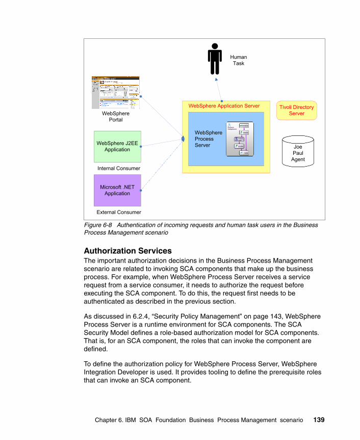
Figure 6-8 Authentication of incoming requests and human task users in the Business Process Management scenario
Authorization ServicesThe important authorization decisions in the Business Process Management scenario are related to invoking SCA components that make up the business process. For example, when WebSphere Process Server receives a service request from a service consumer, it needs to authorize the request before executing the SCA component. To do this, the request first needs to be authenticated as described in the previous section.
As discussed in 6.2.4, “Security Policy Management” on page 143, WebSphere Process Server is a runtime environment for SCA components. The SCA Security Model defines a role-based authorization model for SCA components. That is, for an SCA component, the roles that can invoke the component are defined.
To define the authorization policy for WebSphere Process Server, WebSphere Integration Developer is used. It provides tooling to define the prerequisite roles that can invoke an SCA component.
WebSphere Application Server
WebSphere J2EEApplication
Microsoft .NETApplication
WebSpherePortal
WebSphereProcessServer
receive
reply
invoke
humantask
invoke
ProcessComponent
receivereceive
replyreply
invokeinvoke
humantask humantask
invokeinvoke
ProcessComponent
HumanTask
Internal Consumer
External Consumer
JoePaul
Agent
Tivoli DirectoryServer
Chapter 6. IBM SOA Foundation Business Process Management scenario 139

As shown in Figure 6-9, WebSphere Integration Developer is used to define Quality of Service (QOS) qualifiers for the Interface of the SCA component. The qualifier of interest is Security permission, which defines the roles required to invoke the component. These roles are defined in the user repository, which in this case is Tivoli Directory Server.
Figure 6-9 Using the SCA Qualify of Service Qualifier Security permission to set the roles that can invoke the SCA components
140 Understanding SOA Security Design and Implementation

Confidentiality and Integrity ServicesIn the Business Process Management scenario as shown in Figure 6-10 on page 142, the confidentiality and integrity of messages to and from WebSphere Process Server are important. This includes incoming and outgoing service requests, and all interaction with human tasks. As shown on the diagram, this can be implemented with WS-Security or SSL and is implemented at the WebSphere Application Server level.
Note: The SCA Security Model is covered in the SCA Assembly Model Specification, which can be found at:
http://www.osoa.org/display/Main/The+Assembly+Model
The SCA Policy Framework defines two main types of security policies:
� Interaction Policies govern the communications between clients and service providers and typically applies to Services and References. The interaction policy is concerned with client and service provider authentication and message protection.
� Implementation Policies govern the security constraints on service implementations and typically apply to components. This includes access control and identity delegation.
Chapter 6. IBM SOA Foundation Business Process Management scenario 141

Figure 6-10 Confidentiality and integrity of incoming and outgoing requests and human task requests in the Business Process Management scenario
Audit ServicesWebSphere Process Server provides integration with Common Event Infrastructure (CEI). Events in Common Base Event (CBE) format can be generated for different activities in WebSphere Process Server.
In addition, other IT Security Services called by WebSphere Process Server can generate their own audit data. Examples include Tivoli Federated Identity Manager for identity mediation (via ESB integration) or Tivoli Directory Server. Audit data from these sources can be centralized by Tivoli Compliance Insight Manager for later reporting and analysis.
6.2.3 Security Enablers
A directory, such as Tivoli Directory Server, is required by WebSphere Process Server as a repository for users that invoke business processes and interact with business processes via human tasks.
WebSphere Application Server
WebSphere J2EEApplication
Microsoft .NETApplication
WebSpherePortal
WebSphereProcessServer
receive
reply
invoke
humantask
invoke
ProcessComponent
receivereceive
replyreply
invokeinvoke
humantask humantask
invokeinvoke
ProcessComponent
HumanTask
Internal Consumer
External Consumer
CICS TS 3.1
WebSphere Information Services
Director (WISD)
Enterprise Information System
Information Service
WS-Security
WS-Security
SSL
SSL
WS-Security
SSL
142 Understanding SOA Security Design and Implementation
Cryptographic functions are required to meet any confidentiality and integrity requirements for message protection in WebSphere Process Server.
Intrusion prevention solutions from the IBM ISS portfolio can be used to secure the network between WebSphere Process Server and the consumers of its services.
6.2.4 Security Policy Management
Security Policy Management for this scenario involves security policies for securing WebSphere Process Server, as well as security policies for applications hosted in WebSphere Process Server.
Security policies for securing WebSphere Process Server include:
� Authentication and audit policies of the operating system on which WebSphere Process Server runs
� Firewall policies that control network access to the WebSphere Process Server machine/cluster
� Information in the underlying WebSphere Application Server’s Global Security configuration
� Policies in the configuration of the LDAP staff plug-in
At the application level, security policies are usually authored in WebSphere Integration Developer at the same time as the application. Those policies are stored in deployment descriptors that are deployed with the application. Examples of these security policies include:
� Data protection policies that dictate whether SSL is used for transport-level security or WS-Security for message-level protection
� Authorization policies, specifying role-based security permissions on SCA components
6.2.5 Governance and Risk Management
Incorporating business process management into an SOA solution makes it even more crucial that business and IT are aligned, because the business processes are explicitly represented in the IT infrastructure. The SOA governance board will coordinate the involvement across different aspects of the business to ensure that the specification and planned implementation of the business processes are aligned with the overall enterprise goals. The SOA governance board will be responsible for assuring stakeholders that the SOA-based implementation of the business processes does not reduce the overall security around providing this business function.
Chapter 6. IBM SOA Foundation Business Process Management scenario 143

6.3 Summary
The application of the IBM SOA Security Reference Model to the SOA Foundation Service Creation scenario has been described in this chapter. There are many different security issues with which to contend, and these must be applied across the different components of the scenario. This chapter is therefore usable as a checklist in determining where security can be applied to a real client environment.
144 Understanding SOA Security Design and Implementation

Part 3 Securing the Service Creation scenario
Part 3 provides an end-to-end working example representing the direct exposure of existing CICS applications as services and securing the exposed service realization example for the IBM SOA Foundation Service Creation scenario.
Part 3
© Copyright IBM Corp. 2007. All rights reserved. 145

146 Understanding SOA Security Design and Implementation

Chapter 7. Business scenario
In this chapter, we describe the business context and the requirements for our sample implementation, a scenario that involves two hypothetical corporations - ITSOTelco and ITSOBank. The scenario introduced in this chapter and the solution design and implementation in the chapters that follow are considered from the perspective of both organizations.
7
© Copyright IBM Corp. 2007. All rights reserved. 147

7.1 Business model
Descriptions of the initial context of the ITSOBank and ITSOTelco organizations are provided here, along with insight on the key business drivers and IT challenges the organizations are facing.
7.1.1 Overview
The overview explains the background of the example scenario and gives a short description of the companies involved.
The corporations involved in the scenario are:
� lTSOTelco
A large telecommunications company servicing both individuals (retail customers) and corporate customers, ITSOTelco believes in providing its corporate customers with a rich, integrated user experience. Their goal is to deliver seamless interactions for its customers using browsers and mobile devices.
� ITSOBank
A progressive retail banking corporation looking for new ways to serve its customers, ITSOBank is looking for new ways to reuse existing application assets to improve the service that IT delivers to the business.
ITSOBank has partnered with ITSOTelco to provide a new service to users who are both ITSOBank employees and ITSOTelco corporate customers. ITSOBank employees will be able to access their own account information at ITSOBank from ITSOTelco’s customer portal. Employees will be able to check their account information at ITSOTelco without having to access an ITSOBank application or log in a second time. Figure 7-1 illustrates the business vision for the intended capability.
Figure 7-1 Business vision
148 Understanding SOA Security Design and Implementation

7.1.2 Initial context - ITSOTelco
ITSOTelco has developed a portal to offer services to corporate customers. ITSOBank is one of their corporate customers, and its employees are therefore users of the ITSOTelco Portal.
The first service that ITSOTelco wants to offer its users is the ability to retrieve the current balance of their bank accounts in the portal. Later, other services are planned to be consumed by the portal to provide more integration for the ITSOBank employees.
7.1.3 Initial context - ITSOBank
Figure 7-2 depicts the initial IT context for ITSOBank. The IT infrastructure shown in the figure outlines the way to access the banking application via a CICS client, for example, a 3270 terminal. The underlying security for the CICS application is provided by RACF. Services and components that are not vital to understand the scenario have been omitted from the figure for clarity.
Figure 7-2 ITSOBank initial IT context
CICS
z/OS
RACF
application1
Database
CICS Client
Outside Zone Demilitarized Zone
Production Zone Internal Network
Mngmt. Zone
SAF
Chapter 7. Business scenario 149

7.1.4 Preliminary SOA engagement
ITSOBank has performed a series of workshops with the executive management team and major stakeholders to gain a better understanding of the company’s business objectives and IT challenges. ITSOBank views SOA as a strategic initiative that they want to pursue for both integration and application development at the enterprise level. ITSOBank desires a transition to SOA that can leverage existing applications and infrastructure.
To facilitate the adoption of SOA, the company wants to establish early proof points in phases:
� Phase 1: Expose the getBalance functionality via a service component.
In Phase 1, a specific function, getBalance, of the banking application hosted by the CICS Transaction Server will be exposed indirectly by creating a middle-tier Web service to access CICS. This is shown in Figure 7-3.
Figure 7-3 Using the CICS Transaction Gateway to access CICS from WebSphere Application Server
� Phase 2: Secure the Web service by applying the IBM SOA Security Reference Model.
WAS
CICS Transaction
GatewayJCA
Outside Zone Demilitarized Zone Production Zone Internal Network
Management Zone
CICS
z/OS
RACF
application1
Database
SAF
150 Understanding SOA Security Design and Implementation

The model will be applied to both the ITSOTelco and ITSOBank aspects of the solution.
7.1.5 Business logic
The business logic for retrieving the current balance of an account is implemented in a CICS application. Because the service will be indirectly exposed, the middle-tier will only be used to expose the services from the CICS application and will contain no business logic.
In order to accomplish Phase 1 of the project, ITSOBank has developed a simple online banking application that runs on WebSphere Application Server. The solution is currently in its first release and is only available internally within the bank for access by developers. As such, the application presently has limited functionality and limited security. It provides a single Web service to query the balance of an account by calling the corresponding function in the CICS application.
Figure 7-4 shows the architecture after the deployment of the Web application.
Figure 7-4 ITSOBank application
WAS
CICS Transaction
Gateway
WAS Soap Handler
ITSOBanker 2007 JCA
Outside Zone Demilitarized Zone Production Zone Internal Network
Management Zone
CICS
z/OS
RACF
application1
Database
SAF
Chapter 7. Business scenario 151

7.1.6 Authentication and authorization
Under z/OS, the concept of pluggable security is important; it means that any security product or component can be plugged into the z/OS operating system. This is possible through the System Authorization Facility (SAF) available under z/OS.
As shown in Figure 7-5, at ITSOBank, security in the CICS environment is handled by RACF. As a consequence, every employee of ITSOBank has a RACF account that allows them to work with the CICS application.
Figure 7-5 Using RACF with CICS
For Phase 1 of this SOA project, authentication and authorization are handled entirely within the CICS environment.
An explanation of the basic concepts of how security is handled in the CICS environment using SAF and RACF can be found in “z/OS security” on page 456.
CICS
z/OS
RACF
application1
Database
SAF
152 Understanding SOA Security Design and Implementation

7.2 Business requirements
This section describes the business requirements (BRs) for Phase 2 of the SOA project: securing the ITSOBank scenario. These requirements have been received from the principal sponsors of the project and focus on security:
� BR1: Reuse existing application functionality.
The purpose of this initiative is not to implement new applications, but rather to reuse existing applications in new ways.
� BR2: Make the services easy to consume.
The goal is to drive rapid adoption of the services being offered to business partners, so the effort to consume these services should be low.
� BR3: Security must not be compromised when exposing application capability in new ways.
Secure access to information, especially beyond the corporate boundary, is critical. The security of the environment must not be reduced when access is enabled from ITSOTelco.
� BR4: Auditing must meet regulatory requirements.
Linked with BR3, audit trails must be able to identify the individual user that was performing a transaction at every point in the transaction.
� BR5: Account data must be protected.
Whether in transit or at rest, users’ account data must be protected from unauthorized disclosure.
7.3 Security requirements
This set of technical security requirements (SRs) primarily support business requirements BR3 and BR4. As is usually the case, the technical requirements draw out many more facets than the business requirements:
� SR1: Authentication to the Web service
Whether the route to the Web service originates within the ITSOBank organization or from a business partner location, users accessing the service must be positively and uniquely identified. No reliance must be placed on system or application identities. For example, it must be known that it is user Joe accessing the Web service, not the portal application at ITSOTelco.
Chapter 7. Business scenario 153

� SR2: Authentication to CICS Transaction Gateway
Users must authenticate to RACF using their own user identity and not a shared service/application login. The user’s RACF password must only be stored in RACF itself and not in any intermediate identity stores.
� SR3: Identity mapping
The user’s external user ID and their RACF user ID might not always be the same, but a one-to-one mapping between them has to be possible to support the requirement for positive and unique user identification.
� SR4: Authorization
Access to the services is only granted to service consumers who have been granted authority to use them.
� SR5: Centralized policy management
All security policies must be stored in a centralized policy store for ease of management and audit.
� SR6: Transport level security (TLS)
The communication channel from service consumers beyond ITSOBank must be encrypted using transport level security, such as Secure Sockets Layer (SSL)/TLS.
� SR7: Message integrity
In order to assure the end-to-end integrity of service requests and responses, the content of these messages must be signed.
� SR8: Demilitarized zone (DMZ) termination of inbound requests from partners
For Web service requests originating outside of ITSOBank, a termination point is required in the DMZ before requests are proxied to the network where the Web service is deployed. At a minimum, the DMZ termination point must perform content validation, authentication, coarse-grained authorization, and audit.
� SR9: Auditing
Each component of the solution has to be enabled for auditing. A mechanism has to be available to submit, persistently store, and report on audit data.
� SR10: Use of standards
The solution should employ applicable open standards for security management in SOA environments. This assures maximum interoperability with minimal customization.
� SR11: Account recertification
The accounts of every employee have to be recertified every three months.
154 Understanding SOA Security Design and Implementation

� SR12: Security token standards
The SOA Governance board has provided a guideline for use of signed Security Assertion Markup Language (SAML) 2.0 assertions for identity assertions from external service consumers. They have also provided a guideline to use unsigned SAML 1.1 security tokens for identity assertions within the enterprise.
7.4 Summary
The business and technical aspects of the goals of this scenario have been presented, along with more detailed requirements. The next chapter presents a solution that can meet these requirements.
Chapter 7. Business scenario 155

156 Understanding SOA Security Design and Implementation

Chapter 8. Solution design
In this chapter, the solution design is presented for the ITSOBank and ITSOTelco example. The following aspects are covered:
� Solution overview� Business Security Services� IT Security Services� Security Enablers� Security policy management� Governance and Risk Management
8
© Copyright IBM Corp. 2007. All rights reserved. 157
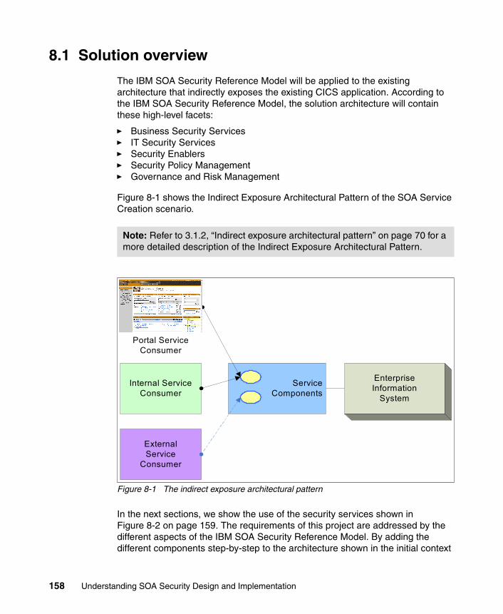
8.1 Solution overview
The IBM SOA Security Reference Model will be applied to the existing architecture that indirectly exposes the existing CICS application. According to the IBM SOA Security Reference Model, the solution architecture will contain these high-level facets:
� Business Security Services� IT Security Services� Security Enablers� Security Policy Management� Governance and Risk Management
Figure 8-1 shows the Indirect Exposure Architectural Pattern of the SOA Service Creation scenario.
Figure 8-1 The indirect exposure architectural pattern
In the next sections, we show the use of the security services shown in Figure 8-2 on page 159. The requirements of this project are addressed by the different aspects of the IBM SOA Security Reference Model. By adding the different components step-by-step to the architecture shown in the initial context
Note: Refer to 3.1.2, “Indirect exposure architectural pattern” on page 70 for a more detailed description of the Indirect Exposure Architectural Pattern.
ServiceComponents
Internal Service Consumer
EnterpriseInformation
System
ExternalService
Consumer
Portal Service Consumer
158 Understanding SOA Security Design and Implementation

described in Figure 7-2 on page 149, the diagram will evolve to the security solution architecture in Figure 8-14 on page 180.
Figure 8-2 shows a logical architecture to meet the requirements laid out in Chapter 7, “Business scenario” on page 147 and how the IBM SOA Security Reference Model is applied to the architecture. In this example, the ITSOTelco Portal originates the service request. A DataPower XS40 appliance is serving the purpose of both an XML firewall and a Web services gateway. It acts as a proxy and provides the first layer for the defense in-depth strategy for the complete solution. WebSphere Application Server hosts the service that accesses CICS.
Figure 8-2 Applying the IBM SOA Security Reference Model
8.2 Business Security Services
In this section, the Business Security Services are specified at the business level. Requirements from 7.2, “Business requirements” on page 153 will be addressed in this section.
Note: A detailed discussion about applying the IBM SOA Security Reference Model can be found in Chapter 3, “IBM SOA Foundation Service Creation scenario” on page 67.
Security Policy Management
Business Security Services
IT Security Services
WebSphere Application
Server/Portal
DataPowerApplicance
WebSphere Application
ServerCICS
Fire
wal
l
Fire
wal
l
Security Enablers
Chapter 8. Solution design 159

8.2.1 Compliance and Reporting
Audit and reporting produce data required for verifying and demonstrating compliance. Reports from Tivoli Compliance Insight Manager. which are based on the audit records generated by Tivoli Identity Manager, will verify that BR4 (Auditing to regulatory requirements) and SR11 (Account recertification) are being achieved.
8.2.2 Data Protection, Privacy, and Disclosure Control
Policies for protection of data in transit and at rest need to be developed to meet requirement BR5 (Protecting account data). These policies include access to account databases (at rest) and message protection policies for data in transit. Requirements for this are described in SR6 (Transport level security) and SR7 (Message integrity). For more technical detail, see 8.3.4, “Confidentiality Services” on page 170 and 8.3.5, “Integrity Services” on page 171.
There are no privacy or disclosure control requirements in this example.
8.2.3 Non-repudiation Services
The ITSOBanker2007 application provides read-only access to ITSOBank data. There are no requirements for Non-repudiation Services. It is anticipated that non-repudiation requirements might be added as the scope of the SOA adds services that can modify ITSOBank data.
8.2.4 Identity and Access
ITSOBank is managing user life cycles by connecting the Human Resources (HR) system to the identity management system. The HR system is considered the authoritative resource to feed identities to the repositories and to provide necessary identity information, such as job roles in specific systems.
The policies listed in 8.5.1, “Policy administration” on page 176 ensure that each employee owns the correct accounts, is a member of the correct groups, and has access to systems required for their job role. Providing self-care capabilities is a function of the Identity Services as is account recertification, which is a requirement from ITSOBank.
8.2.5 Trust Management
The business aspects of trust management, such as relationship and liability management, are assumed to be established prior to the development of this
160 Understanding SOA Security Design and Implementation

technical solution design. Without them, there is no basis to build the cross-enterprise solution from ITSOTelco to ITSOBank.
A loosely coupled trust relationship model will be used as introduced in Figure 2-17 on page 40.
On the technology aspect of trust management, ITSOBank agrees to trust Security Assertion Markup Language (SAML) 2.0 security tokens signed with a private key issued by ITSOTelco’s certificate authority.
8.2.6 Secure Systems and Networks
This section describes how ITSOBank secures its systems and networks. It is important to know that the concepts mentioned here are best practices and standards and not necessarily specific to SOA security:
� Secure networks
The network is designed to address several levels of protection and control and consists of several zones. Between each zone, a firewall is installed (Figure 8-2 on page 159). Firewall rules need to achieve the following objectives:
– Traffic from the Outside zone to the demilitarized zone (DMZ) must be restricted to only permit connection to the HTTPS port on the DataPower appliance.
– Traffic from the DMZ to the Production zone should be restricted to only permit connections from the DataPower appliance to the HTTP port on the WebSphere Application Server instance running the ITSOBanker2007 application.
– Traffic to the Management zone should only be permitted from the DMZ and Production zones.
– Connections to the TFIM Security Token Service should only be permitted from the DataPower appliance and the WebSphere Application Server instance running the ITSOBanker2007 application.
– Access to the CICS transaction gateway in the internal network should be restricted to only originate from the WebSphere Application Server instance running the ITSOBanker2007 application.
Note: For further information, we recommend Appendix A, “Method for Architecting Secure Solutions” in Enterprise Security Architecture Using IBM Tivoli Security Solutions, SG24-6014.
Chapter 8. Solution design 161

� Secured systems:
– ITSOBank uses Tivoli Access Manager for Operating Systems for system hardening. This includes implementing account login policies, removing access to network services not required for the solution, and controlling access to files and other resources on production servers.
� XML firewall
The XML firewall (DataPower XS40 appliance) secures incoming XML and SOAP traffic. It is a first level of defense that will provide these security functions:
– XML schema validation– Message authentication– Secure Sockets Layer (SSL) termination– SSL acceleration
8.3 IT Security Services
In this section, we summarize the IT Security Services from the IBM SOA Security Reference Model and how they will be applied in this design.
8.3.1 Identity Services
The Identity Services described in “Identity Services” on page 74 are composed of the following components:
� Identity foundation� Identity provisioning� Identity propagation
Identity foundationThere are two user repositories that are used in the solution: a directory server used by the middle-tier WebSphere Application Server and the RACF database that contains the identities of registered users of the CICS banking application. The directory server needs to be deployed; the RACF database is already implemented.
Figure 8-3 on page 163 shows that a Lightweight Directory Access Protocol or LDAP user registry is added to the solution architecture. It stores common identity information for the enterprise. In this scenario, IBM Tivoli Directory Server (TDS) is deployed. The RACF identity database is also shown, because it is part of the z/OS System.
162 Understanding SOA Security Design and Implementation

Figure 8-3 Identity foundation
Identity provisioningIn order to add, delete, or modify individual account information, an identity provisioning solution needs to be implemented. IBM Tivoli Identity Manager provides a secure, automated, and policy-based user life cycle management solution. It guarantees that only the entitled identities with the correct attributes are provisioned to the LDAP directory and the RACF database.
Identity Manager ensures that the RACF user ID of each employee in ITSOBank is synchronized with the uniqueIdentifier attribute of the user object in the LDAP directory. This attribute is used when identity mapping is required from the identity in the Web service call to the RACF identity.
Figure 8-4 on page 164 shows the architecture including Tivoli Identity Manager (TIM in the picture) with adapters for:
� IBM Tivoli Directory Server
� RACF
WAS
WAS Soap Handler
ITSOBanker 2007 JCA
Outside Zone Demilitarized Zone Production Zone Internal Network
Management Zone
TDS
z/OS
CICS Transaction
Gateway
CICS
RACF
application1
Database
SAF
Chapter 8. Solution design 163

� IBM Tivoli Access Manager for e-business (introduced in 8.3.2, “Authentication Services” on page 165)
In order to perform authentication and authorization in WebSphere Application Server, global security is activated and the Tivoli Directory Server instance is configured as the user repository.
Figure 8-4 Identity provisioning
Identity propagationIn this solution, identity propagation deals with token mediation and identity mapping, which can transform the format and content of identities in the solution. This capability is provided by a standard component of Tivoli Federated Identity
Tip: For more information about how to configure security in WebSphere Application Server, the IBM Redbooks publication IBM WebSphere V6.0 Security Handbook, SG24-6316, is recommended.
WAS
CICS Transaction
Gateway
WAS Soap Handler
ITSOBanker 2007 JCA
Outside Zone Demilitarized Zone Production Zone Internal Network
Management Zone
CICS
TDS
z/OS
RACF
application1
DatabaseTIM
Database
TAM
SAF
164 Understanding SOA Security Design and Implementation

Manager called Security Token Service (STS). STS is an implementation of the WS-Trust specification and has the capabilities to validate an inbound token, transform the identity representation, perform other functions such as authorization, and then issue a new token based on policies (Figure 8-5).
Figure 8-5 Federated Identity Manager Security Token Service
8.3.2 Authentication Services
Authentication of Web service requests in this scenario is handled by calling the Security Token Service (STS) of IBM Tivoli Federated Identity Manager. The STS manages the handling of security tokens that are used to authenticate the Web service requests. To transmit the relevant information from the point of contact to the STS, the request is structured according to the WS-Trust specification that defines a standardized format for security token requests. To determine how to process the request, the STS uses defined attributes, such as AppliesTo, Issuer, and Token Type. To process the tokens, the STS uses modules, module instances, and trust service chains.
For each type of token, the STS has a security token module that handles the trust relationship. These modules are responsible for creating tokens, validating tokens, and exchanging token types. Trust modules perform specific functions based on the mode in which they operate. In order to execute the complete and correct sequence of necessary functions, the STS configures trust module instances into trust service chains. Trust service chains are groups of module instances that are configured to be used together.
TrustClient
TFIMSecurity Token Service (STS)
(Trust Chain)
RST : Issuer, AppliesTo, <Token>
RSTR : StatusCode, <NewToken>
WebSphere Application Server(inbound/outbound SOAP, JCA, JDBC)
WebSphere Enterprise Service BusWebSphere Message BrokerDataPower SOA Appliances (XS40,XI50)
WS- Trust
Chapter 8. Solution design 165

The STS is used to transform security tokens and map identities to ensure that a valid representation of the user’s identity is propagated throughout the application.
Figure 8-6 shows the ITSOTelco Portal invoking the ITSOBank Web service from outside the ITSOBank intranet. The DataPower appliance, used as a first line of defense, has to authenticate these requests.
Figure 8-6 Access to the service via the DataPower appliance
This leads to the following system boundaries where security tokens are exchanged and trust service chains have to be configured (Figure 8-7 on page 167).
ITSOTelco Portal
DataPowerAppliance
WAS
CICS Transaction
Gateway
WAS SOAP Handler
ITSOBanker 2007 JCA
Outside Zone Demilitarized Zone Production Zone Internal Network
Management Zone
CICS
z/OS
RACF
application1
Database
SAF
166 Understanding SOA Security Design and Implementation

Figure 8-7 Identity token exchange
� ITSOTelco Portal to DataPower appliance
When calling the ITSOBank service, a signed SAML 2.0 security token is included in the Web service request by the ITSOTelco Portal, using the Federated Identity Manager WSSM Token Generator. The ITSOTelco Portal generates this security token based on the authenticated identity for the user session in the portal. The DataPower appliance validates the SAML 2.0 security token by validating the assertion’s signature. If signature validation is successful, the DataPower appliance extracts this token and sends the SAML 2.0 token to the TFIM STS in a WS-Trust message. If the token is authenticated and access to the Web service is authorized, the STS issues a new SAML 1.1 security token and returns it to the DataPower appliance.
Figure 8-8 shows the sequence of the trust chain and which modules are configured into the trust chain.
Figure 8-8 Trust chain - authenticating and authorizing external requests to DataPower XS40
� DataPower appliance to WebSphere Application Server
The SAML 1.1 token issued by the STS is sent to the WebSphere Application Server, which authenticates the request by using the Federated Identity Manager WSSM Token Consumer and the STS.
ServiceComponents
ITSOTelco Portal CICS
TFIM STS(ITSOBank)
SAML 2.0token Passticket
WebSphere Application Server
DataPower appliance
SAML 1.1token
TFIM STS(ITSOTelco)
Validate incoming SAML 2.0 token
Map incoming user id
Authorize request
Issue SAML 1.1
token
Chapter 8. Solution design 167

The trust chain depicted in Figure 8-9 shows the appropriate sequence. This trust chain requires a SAML token or a user name token as the inbound security token. After authenticating and authorizing the request, a SAML token is issued.
Figure 8-9 Trust chain - authentication and authorization to WebSphere Application Server
� WebSphere Application Server to CICS Transaction Gateway
To connect to the CICS Transaction Gateway, map the authenticated user identity within WebSphere Application Server to the RACF user ID. Because Tivoli Identity Manager is configured to store the RACF ID of each employee as an attribute in the Tivoli Directory Server, the mapping mechanism uses this attribute to obtain the RACF ID and generate a passticket.
The following trust chain in Figure 8-10 shows the configured modules and the sequence.
Figure 8-10 Trust chain - authenticating to CICS Transaction Gateway
8.3.3 Authorization Services
Here we need to look at the service authorization, as well as authorizing access to J2EE resources on WebSphere Application Server.
Service authorizationService authorization is performed as part of the trust chain processing in the Federated Identity Manager STS. An authorization module instance is added to the trust chain so that authorization can be performed based on the Web service operation being invoked. The authorization decisions are made by Access Manager for e-business.
Validate incoming SAML 1.1 token
Map incoming user id
Authorize request
Issue SAML 2.0
token
Validate incoming Username Token
Map incoming user id to RACF user id
Issue Passticket
168 Understanding SOA Security Design and Implementation

Following successful authentication of the user making the request, the authorization decision is based on all of these:
� The user attempting to access the service� The Web service being accessed� The operation being invoked within the Web service
Authorizing access to J2EE resourcesThe ITSOBank banking application implements the J2EE role-based authorization model to perform authorization checks within the application. To request authorization decisions when a J2EE resource is accessed, WebSphere Application Server can use any third-party authorization provider implementing the JACC provider. The Java Authorization Contract for Containers (JACC) defines a contract between Java 2 Platform, Enterprise Edition (J2EE) containers and authorization providers. Using the JACC provider of Access Manager for e-business, the authorization decisions within the application are delegated to Access Manager for e-business (Figure 8-11 on page 170).
Using the JACC provider of Access Manager for e-business also offers the functionality to centrally store and manage the policies because the JACC provider communicates with the Access Manager Policy Server to persist the J2EE security configuration data. It also allows you to integrate with the audit subsystem used by Access Manager to audit the authorization decisions made by Access Manager for e-business.
Chapter 8. Solution design 169

Figure 8-11 Components - JACC Provider
8.3.4 Confidentiality Services
In this section, the solution for meeting requirement “SR6: Transport level security (TLS)” on page 154 is explained.
Transport level security is applied to the following communication channels:
� Communication between the ITSOTelco Portal and the DataPower appliance
To secure the communication channel for the service request, HTTPS (using SSL) between the components is implemented. The DataPower appliance terminates the HTTPS session of the service request.
� Communication between WebSphere Application Server and the Federated Identity Manager STS
The Federated Identity Manager WSSM token consumer and the WS-Trust client used to obtain RACF credentials on behalf of the user are exchanging
ITSOTelcoPortal
DataPowerAppliance
WAS
CICS Transaction
Gateway
WSSM
JAASLogin Module
JAASLogin Module
WAS Soap Handler
ITSOBanker 2007 JCA
Outside Zone Demilitarized Zone Production Zone Internal Network
Management Zone
WS-Trust client
CICS
Validate
Map
Authz
New Token
Validate
Map
New Token
TDS TAM
FIM STS
z/OS
RACF
application1
DatabaseTIM
SAF
Database
JACC interface
TAM JACC
provider
170 Understanding SOA Security Design and Implementation

WS-Trust messages with the Federated Identity Manager STS. Because there are no intermediaries between these components, SOAP over HTTPS is considered the appropriate mechanism to secure these channels. Again, a mutually authenticated connection is recommended.
� Communication to the IBM Tivoli Directory Server
The Tivoli Directory Server is the enterprise user registry containing user identities and confidential information, such as passwords and the RACF ID. To secure the communication between any component and the directory, the services have to be configured to use secure LDAP (LDAPS) to encrypt information from and to the directory server.
� Communication between the Access Manager components
Access Manager uses SSL for the communication to the Access Manager components by default. There is no additional configuration needed. Only setting up the secure communication to the directory server needs additional configuration.
� Communication between Identity Manager and the adapters for Access Manager for e-business, RACF, and Tivoli Directory Server
Identity Manager uses specific adapters for the target system to provision user identities. The communication between the adapters and the Identity Manager runtime is secured using SSL.
� Communication between WebSphere Application Server and the CICS Transaction Gateway
The communication between WebSphere Application Server and the CICS Transaction Gateway is secured using SSL.
8.3.5 Integrity Services
In the ITSOBank scenario, data protection is required to protect the cryptographic keys stored in the keystores, security configuration files, and the data stored in the database used by the CICS application and the audit data submitted by individual components among others.
IBM Tivoli Access Manager for Operating Systems is used to protect the file systems that contain cryptographic keys and configuration files. Files can be protected from unauthorized access and modification, using finer-grained constructs than are available with native operating system security. The system process from which files are accessed can be relevant, for example, a configuration file might be able to be accessed by the process that uses it but not by a text editor.
Chapter 8. Solution design 171

Message protection protects the data in transit from being:
� Modified without detection (message integrity)� Sent from a masquerading party (message origin authentication)
This is achieved by digitally signing a combination of the message body (or its parts) and header (or its parts).
A SOAP message travels from the ITSOTelco Portal to the ITOSOBanker2007 application, passing through the DataPower XS40 along the way. Secure protocols, such as SSL/TLS, ensure the confidentiality and integrity of the message during transmission, but because the messages can be received and forwarded by intermediaries, secure end-to-end communication cannot be guaranteed because transport level security is point-to-point. After the message is received and decrypted at the transport level, message level security is needed to protect the message.
The body of messages from the ITSOTelco Portal will be digitally signed. The signature will be verified by the ITSOBanker2007 application upon receipt of the message. This is an example of end-to-end message protection.
To verify the message signatures, a security management process needs to be in place to manage and exchange the certificates. Figure 8-12 on page 173 illustrates which certificates are needed at the ITSOTelco Portal and the ITSOBanker2007 application for signing requests and responses.
Note: For further details about message confidentiality and integrity, refer to the Web Services Security, SOAP Message Security (WS-Security 2004) at:
http://www.oasis-open.org/committees/download.php/16790/wss-v1.1-spec-os-SOAPMessageSecurity.pdf
172 Understanding SOA Security Design and Implementation

Figure 8-12 Message signature and encryption
WebSphere Application Server’s WS-Security processing validates the content of incoming requests to ensure that the message signature is valid.
8.3.6 Audit Services
To meet the regulatory requirements, auditing needs to be able to identify the individual user who was performing a transaction at every point in the transaction (see “BR4: Auditing must meet regulatory requirements.” on page 153). The security requirement SR8 requires that every component has to be enabled for auditing and that an infrastructure has to be in place to submit, persistently store, and report on audit data submitted as events.
Tivoli Compliance Insight Manager (TCIM) will be used to centralize and aggregate audit records from the various components in the solution.
ITSOTelcoPortal ITSOBanker2007
Keystore Keystore
Service request Body signed with private key of ITSOTelco Portal
Service responseBody signed with private key of ITSOBanker2007
ITSOTelco signing keyITSOBank CA certificate
ITSOBank signing keyITSOTelco CA certificate
Chapter 8. Solution design 173

Figure 8-13 Audit services
Because every authentication and authorization decision has to generate an audit event, the following components are identified to be enabled for auditing:
� DataPower appliance� Federated Identity Manager STS� Access Manager for e-business� Identity Manager� WebSphere Application Server� ITSOBanker2007 application� CICS application
The main components for authentication and authorization are Access Manager for e-business and Federated Identity Manager. Because the DataPower appliance is configured to call the Federated Identity Manager STS, the audit events are generated during the processing of the trust service chain.
ITSOTelcoPortal
DataPowerAppliance
WAS
CICS Transaction
Gateway
WSSM
JAASLogin Module
JAASLogin Module
WAS Soap Handler
ITSOBanker 2007 JCA
Outside Zone Demilitarized Zone Production Zone Internal Network
Management Zone
WS-Trust client
CICS
Validate
Map
Authz
New Token
Validate
Map
New Token
TDS TAM
FIM STS
z/OS
RACF
application1
DatabaseTIM
SAF
Database
TCIM
174 Understanding SOA Security Design and Implementation

Authorization for J2EE resources uses the JACC provider of Access Manager for e-business, so these events are generated by Access Manager for e-business.
Identity Manager and the CICS application have their own audit services. Identity Manager stores audit events in its relational database and the CICS application keeps its existing audit infrastructure.
One of the benefits of using Compliance Insight Manager in this solution is that it is able to collect and process audit data from a variety of sources and normalize the data so that meaningful analysis and reporting can be performed centrally.
8.4 Security Enablers
Security Enablers are underlying technologies that are invoked by IT Security Services. In this solution, the following Security Enablers are used:
� Cryptographic services are used when signing security tokens and messages (XML Signature) and for transport-level encryption (SSL) between the ITSOTelco Portal and the ITSOBank XML Firewall.
� Tivoli Directory Server is an LDAP V.3 compliant directory. It is used as the user repository for the non-mainframe solution components at ITSOBank.
� Key Management services are used to generate the X.509 keys used in conjunction with the cryptographic services. These keys are crucial to this solution:
– ITSOBank Message Signing Key
This key is used to sign Web services response messages from ITSOBank to ITSOTelco (and potentially other partners). The distinguished name of this key is CN=signer,O=itsobank,C=US.
– ITSOBank SSL Key
External communications with the DataPower XS40 device are required to use transport level security, that is, HTTP over SSL. The distinguished name of this key is CN=https,O=itsobank,C=US.
– ITSOTelco Message Signing Key
This key is used to sign Web services request messages from ITSOTelco to ITSOBank (and potentially other partners). The distinguished name of this key is CN=signer,O=itsotelco,C=US.
� Firewalls are used between the network zones in the solution to limit the traffic that is able to flow between zones to specific combinations of IP addresses, ports, and protocols.
Chapter 8. Solution design 175

� ISS Proventia Network IPS is used to provide intrusion prevention management for the network. This technology provides the ability to protect transactions at the application layer or the network. This enables the security administrator to reduce exposure to threats and misuse of network resources.
� ISS Proventia ADS is used to ensure there is no misuse of network resources and systems. By looking for anomalous behavior in the network, administrators are alerted immediately to problems that might arise.
� ISS Proventia Host-based products are deployed on the servers and desktops to protect systems from local intrusions and ensure system integrity.
� ISS Proventia Enterprise scanner is used to ensure that systems stay in compliance and have the latest patches and system configurations.
� IBM Tivoli Security Operations Manager is used for security event management. By collecting event data from multiple sources in the solution (for example, firewalls, ISS Proventia security products, operating systems, and application servers), Security Operations Manager is able to detect anomalies based on configured policies and generate alerts for system administrator intervention.
� Network Time Protocol (NTP) provides time synchronization across the environment. Authoritative sources of time are used by both ITSOTelco and ITSOBank to keep their understanding of time consistent. This is required so that the lifetime of security tokens can be enforced without resorting to larger (weaker) security token lifetimes.
8.5 Security policy management
In this section, the facets of Security Policy Management are designed.
8.5.1 Policy administration
Policy administration covers creation, modification, import, and export of security policies using available security management tools. Security policies described here are derived from the ITSOBank scenario business and security requirements listed in 7.2, “Business requirements” on page 153 and 7.3, “Security requirements” on page 153:
� Message protection policies:
– The HTTPS protocol must be used for communication from external service consumers to the DataPower XS40 appliance.
– A signed SAML 2.0 security token is required to invoke the Web service from the ITSOTelco Portal.
176 Understanding SOA Security Design and Implementation

– The Web service messages must be signed.
– The signature method algorithm is RSA-SHA1.
� Provider policies:
– The user accessing the service has to be authenticated.
– The users accessing the service have to be authorized to use the service.
– Authentication to RACF must use the RACF user ID of the service consumer.
– Each component of the solution has to be enabled for auditing and the audit trails have to be able to identify the individual user who was performing a transaction at every point in that transaction.
8.5.2 Policy distribution and transformation
Authorization policies, defined centrally in Access Manager for e-business, are distributed to the Access Manager runtime environments where enforcement will occur. In this solution, the authorization policy is distributed to:
� Federated Identity Manager runtime
Service-level authorization is performed as part of the Federated Identity Manager trust chain processing.
� WebSphere Application Server
JACC-based authorization of EJB™ components of the ITSOBanker2007 application is performed within the WebSphere Application Server instance running the application.
8.5.3 Policy decision and enforcement
The Policy Enforcement Points (PEPs) rely on decisions made by the Policy Decision Points (PDPs). The PDPs contain the security policies defined in the infrastructure. This section outlines the PDPs and PEPs described in the ITSOBank solution architecture. Solution components are described here, detailing their roles with respect to policy decision and enforcement:
� DataPower appliance
The DataPower appliance enforces transport level protection. Because it analyzes incoming requests, it is also the Policy Decision Point.
� Federated Identity Manager
Token validation and token exchange, as well as authorizing incoming requests, are done by Federated Identity Manager. Depending on the incoming token type, Federated Identity Manager plays different roles:
Chapter 8. Solution design 177

– Username token
Username tokens, which contain a password, are typically validated by authentication with Tivoli Access Manager. In this solution, the Username token received by Federated Identity Manager will only contain a user name. Tivoli Access Manager is used to validate that the user exists in the user registry.
– SAML assertions
During the validation process of SAML security tokens, Federated Identity Manager is the decision and enforcement point for authenticating the Web service request by validating the SAML security tokens.
Federated Identity Manager enforces authorization before the service consumer is granted to invoke the Web service. It relies on the authorization decision made by Access Manager for e-business.
� WebSphere Application Server
WebSphere Application Server is the policy enforcement and policy decision point to enforce message level security.
� Access Manager for e-business
Access Manager for e-business is the decision point for authorizing access to requested resources, such as J2EE resources or Web services. It is also the policy decision point for authenticating incoming Web service requests carrying a user name token.
� Identity Manager
Identity Manager is the PDP and PEP for provisioning policies.
� RACF
RACF is the policy decision and policy enforcement point for the CICS application and the CICS Transaction Gateway.
8.5.4 Monitoring and reporting
The policy replication subsystem in Tivoli Access Manager ensures that subscribers to its policy information are notified when changes to the policy have occurred, so that they can retrieve the latest version of the policy from the Tivoli Access Manager Policy Server.
Reporting is available from Tivoli Identity Manager to show users and the systems and resources to which they have access.
178 Understanding SOA Security Design and Implementation

8.6 Governance and Risk Management
Early in the SOA initiative at ITSOBank, an SOA Governance Board was formed. From the security perspective, the SOA Governance Board is responsible for defining security standards for interaction with services, establishing roles and responsibilities for policy administration, and how the services of ITSOBank are made available to partners, such as ITSOTelco.
The risk management exercise performed by delegates of the SOA Governance Board resulted in the security requirements specified in Chapter 7, “Business scenario” on page 147.
8.7 Summary
This concludes the security solution design for accessing ITSOBank’s CICS services from the ITSOTelco. The overall solution design is shown in Figure 8-14 on page 180.
Chapter 8. Solution design 179

Figure 8-14 Complete solution design
Next, the step-by-step process of implementing this solution is shown in Chapter 9, “Technical implementation” on page 181.
ITSOTelcoPortal
DataPowerAppliance
WAS
CICS Transaction
Gateway
WSSM
JAASLogin Module
JAASLogin Module
WAS Soap Handler
ITSOBanker 2007 JCA
Outside Zone Demilitarized Zone Production Zone Internal Network
Management Zone
WS-Trust client
CICS
Validate
Map
Authz
New Token
Validate
Map
New Token
TDS TAM
FIM STS
z/OS
RACF
application1
DatabaseTIM
SAF
Database
TCIM TSOM NTPISS Proventia
180 Understanding SOA Security Design and Implementation

Chapter 9. Technical implementation
This chapter contains configuration instructions for implementing the solution architecture described in the preceding chapter. However, this chapter is not a complete, step-by-step guide for implementing all of the solution design. Installation steps and basic product configuration are not described. In sections, existing knowledge and certain skills are assumed in order to focus on the aspects of constructing the solution that are specific to service-oriented architecture (SOA) Security. This chapter assumes that you have some working knowledge of the products being used.
In this chapter, we cover the following aspects of the technical implementation:
� Implementation scope� Key stores� Adding security to the applications using Rational® Application Developer� Deploying the application components in WebSphere Application Server� Configuring the XML Firewall� Configuring Tivoli Federated Identity Manager� Testing the solution
9
© Copyright IBM Corp. 2007. All rights reserved. 181

9.1 Implementation scope
In terms of the SOA life cycle implementation, this chapter describes the following steps:
� Assemble:
– Add Web services security to ITSO Portal application– Add Web services security to ITSOBanker2007 application
� Deploy:
– Deploy ITSOTelco Portal application– Configure ITSOTelco trust infrastructure– Configure DataPower XS40 XML Firewall– Deploy ITSOBanker2007 application– Configure ITSOBank trust infrastructure
� Manage:
– Examine DataPower XS40 message runtime trace– Examine Tivoli Federated Identity Manager runtime trace
9.2 Key stores
Public Key Infrastructure (PKI) is used throughout this solution to enable message and transport level data protection. The different keys and key stores that have been created are described here and then referenced in subsequent sections. These key stores are also available for download with this IBM Redbooks publication (see Appendix D, “Additional material” on page 461).
9.2.1 Keys
Each of the keys in this section was generated as a self-signed key using the iKeyMan tool from the IBM Global Security Kit (GSKit). GSKit is a component included with many IBM software products, including Tivoli Access Manager and WebSphere Application Server.
Note: Not all aspects of the design are implemented in this chapter. The following design items are not implemented:
� Service-level authorization at the ITSOTelco Portal, ITSOBank XML Firewall, and ITSOBanker2007 application
� User provisioning
� Intrusion prevention
182 Understanding SOA Security Design and Implementation

ITSOBank Message Signing KeyThis key is used to sign Web services response messages from ITSOBank to ITSOTelco (and potentially other partners). The distinguished name of this key is CN=signer,O=itsobank,C=US.
ITSOBank SSL KeyExternal communications with the DataPower XS40 device are required to use transport level security, for example, HTTP over Secure Sockets Layer (SSL). The distinguished name of this key is CN=https,O=itsobank,C=US.
ITSOTelco Message Signing KeyThis key is used to sign Web services request messages from ITSOTelco to ITSOBank (and potentially other partners). The distinguished name of this key is CN=signer,O=itsotelco,C=US.
9.2.2 Key stores
Subsets of the private keys (keys) and public keys (certificates) from section 9.2.1, “Keys” on page 182 have been composed into different key stores to be used throughout the solution. All key stores use the Java Keystore (JKS) format, and the key store passwords are all itso. The contents of the key stores are described in this section.
itsobank.jksUsage: Keys and certificates required for Web services security by the ITSOBanker2007 application.
Contains:
– ITSOBank Message Signing Key– ITSOTelco Message Signing Certificate
itsobank-ssl.jksUsage: Key required for the SSL listener on the DataPower XS40 appliance.
Contains:
– ITSOBank SSL Key
itsotelco.jksUsage: Keys and certificates required for Web services security by the ITSOTelco Portal application.
Chapter 9. Technical implementation 183

Contains:
– ITSOTelco Message Signing Key– ITSOBank Message Signing Certificate
itsotelco-ssl-truststore.jksUsage: Trusted signer certificates when making SSL connections from the ITSOTelco Portal application.
Contains:
– ITSOBank SSL Certificate
9.3 Add Web services security to the ITSOTelco Portal application
The ITSOTelco Portal application needs to be modified to enable message protection and integration with Tivoli Federated Identity Manager for identity mediation. These steps are performed using IBM Rational Application Developer 7.0 by editing the deployment descriptor for the ITSOTelcoPortalWeb project (Figure 9-1 on page 185).
184 Understanding SOA Security Design and Implementation

Figure 9-1 ITSOTelcoPortalWeb deployment descriptor
The applications supplied with this IBM Redbooks deliverable have already had the security settings added, although the sub-sections that follow describe how to perform these same steps.
9.3.1 Configure request generator
The request generator needs to be modified to sign the message body and then call Federated Identity Manager to generate a Security Assertion Markup Language (SAML) 2.0 security token to include with the outbound requests. The steps are:
1. Navigate to the WS Extension tab and select service/AccountJCAService. Then, select the AccountJCA port-qualified name binding.
Chapter 9. Technical implementation 185

2. Expand Request Generator Configuration and click Integrity. Add a new integrity requirement to indicate that the body of the message must be signed (Figure 9-2).
Figure 9-2 Integrity requirement for message body
3. Expand Security Token and add an entry to specify that a SAML 2.0 security token is to be added to the outgoing messages (Figure 9-3).
Figure 9-3 SAML 2.0 security token
4. Navigate to the WS Binding tab.
186 Understanding SOA Security Design and Implementation

5. Expand the Security Request Generator Binding Configuration tab, and click Token Generator.
Add a new entry for how the SAML 2.0 security token will be generated (Figure 9-4 on page 188). Table 9-1 shows the full value for some of the important parameters.
Table 9-1 Values for SAML 2.0 security token
The two properties required for the Callback Handler are shown in Table 9-2.
Table 9-2 Callback handler required properties
At the bottom of the window, enter one final required property so that the Federated Identity Manager Security Token Service is called by the WSSM Token Generator. When finished, click OK.
Table 9-3 Property to call Federated Identity Manager Security Token Service
Parameter Value
Token generator class name
com.tivoli.am.fim.wssm.tokengenerators.WSSMTokenGenerator
Callback Handler
com.tivoli.am.fim.wssm.callbackhandlers.WSSMTokenGeneratorCallbackHandler
Property Value
token.callback.handler.class.name
com.tivoli.am.fim.wssm.callbackhandlers.SAMLACallbackHandler
xml.callback.handler.class.name
com.tivoli.am.fim.wssm.callbackhandlers.JAASSubjectCallbackHandler
Property Value
trust.service.call true
Chapter 9. Technical implementation 187

Figure 9-4 SAML 2.0 token generator
188 Understanding SOA Security Design and Implementation

6. A token generator is also required for the token that signs the body of the message. Create this entry using Figure 9-5 as a guide. When finished, click OK.
Figure 9-5 Signing token configuration
Chapter 9. Technical implementation 189

7. A Key Locator is required to identify the correct signing key. Create a key locator as shown in Figure 9-6. When finished, click OK.
Figure 9-6 Key locator for signing key
190 Understanding SOA Security Design and Implementation

8. Key Information, as shown in Figure 9-7, also needs to be added. The key information links the key locator and security token definitions. When finished, click OK.
Figure 9-7 Key information
Chapter 9. Technical implementation 191

9. Expand Signing Information and add a new entry as depicted in Figure 9-8. When finished, click OK.
Figure 9-8 Signing information
192 Understanding SOA Security Design and Implementation

10.With the new signing information entry selected, add a new Part Reference entry (Figure 9-9). When finished, click OK.
Figure 9-9 Part reference
11.With the new part reference selected, add a new Transform entry (Figure 9-10). When finished, click OK.
Figure 9-10 Transform
After you finish this last step, the request configuration is complete.
9.3.2 Configure response consumer
Responses from ITSOBank need to have their signatures verified. In this section, we explain the configuration steps to achieve this signature verification setup:
1. Navigate to the WS Extension tab and select service/AccountJCAService. Then select the AccountJCA port-qualified name binding.
Chapter 9. Technical implementation 193

2. Expand Response Consumer Configuration, then expand Required Integrity. Add a new integrity requirement to indicate that the body of the message must be signed (Figure 9-11). When finished, click OK.
Figure 9-11 Specifying message integrity requirement for the response body
194 Understanding SOA Security Design and Implementation

3. Navigate to the WS Binding tab. Expand Security Response Consumer Binding Configuration.
Expand Trust Anchor and add a new entry so that the signing certificate from the ITSOBank can be trusted (Figure 9-12). When finished, click OK.
Figure 9-12 Trust anchor
Chapter 9. Technical implementation 195

4. Expand Token Consumer and add a new entry for the public key that will verify the message body’s signature (Figure 9-13). This token appears as a BinarySecurityToken in the message response. When finished, click OK.
Figure 9-13 Token consumer for certificate used to validate the message certificate
196 Understanding SOA Security Design and Implementation
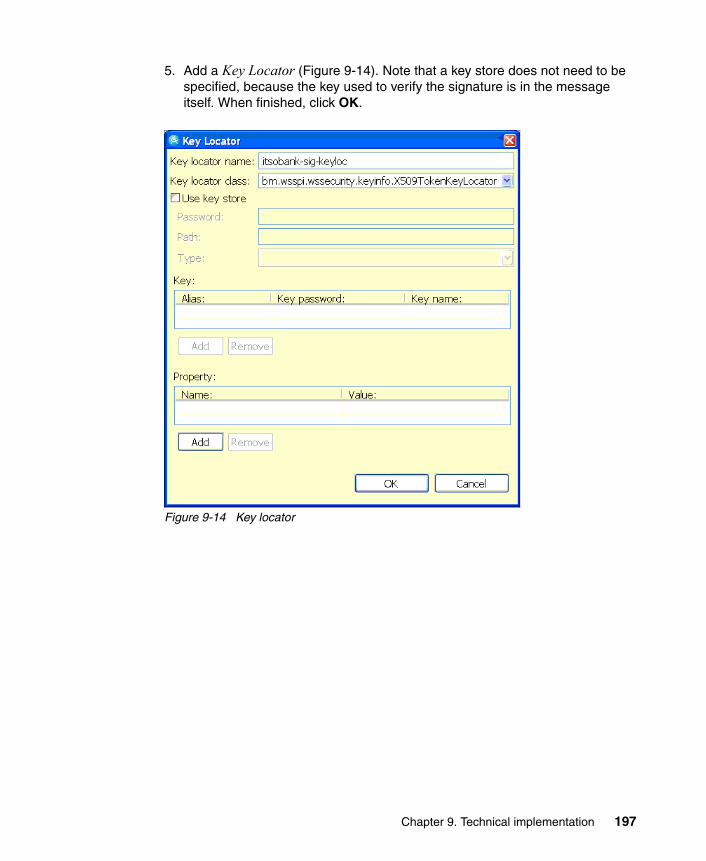
5. Add a Key Locator (Figure 9-14). Note that a key store does not need to be specified, because the key used to verify the signature is in the message itself. When finished, click OK.
Figure 9-14 Key locator
Chapter 9. Technical implementation 197

6. A Key Information entry is required to link the key locator and signing token definitions (Figure 9-15). When finished, click OK.
Figure 9-15 Key information
198 Understanding SOA Security Design and Implementation

7. A Signing Information entry is required (Figure 9-16). When finished, click OK.
Figure 9-16 Signing information
Chapter 9. Technical implementation 199

8. With the new signing information selected, add a new Part Reference (Figure 9-17). When finished, click OK.
Figure 9-17 Part reference
9. With the new part reference selected, add a new Transform (Figure 9-18). When finished, click OK.
Figure 9-18 Transform
The response configuration is now complete.
9.4 Deploy ITSOTelco Portal application
Before we can deploy the application, we need to configure the infrastructure. And after we have installed ITSOTelco Portal, we need to configure the application as well.
200 Understanding SOA Security Design and Implementation

9.4.1 Infrastructure configuration
The WebSphere Application Server profile in which the ITSOTelco Portal will be deployed has the following configuration already completed:
� Administrative and application security has been configured. In the ITSO lab environment, a Tivoli Directory Server instance was shared with Access Manager for e-business and Federated Identity Manager for this purpose.
� Prerequisite steps for using the Web Services Security Management component of Tivoli Federated Identity Manager have been completed, following the instructions in the IBM Tivoli Federated Identity Manager Web Services Security Management Guide Version 6.1.1, GC32-0169-01, in the Tivoli Federated Identity Manager product documentation set:
– The ITFIM_WSSM variable was created.
– The ITFIM_WSSM shared library definition was created.
– The class loader for the WebSphere Application Server instance to be used by the ITSOTelco Portal has been configured to use the ITFIM_WSSM shared library definition.
� The itsotelco.jks key store has been uploaded to the application server instance’s home directory, for example, /opt/IBM/WebSphere/AppServer/profiles/itsotelco.
� The itsotelco-ssl-truststore.jks key store has been uploaded to the application server instance’s home directory, for example, /opt/IBM/WebSphere/AppServer/profiles/itsotelco.
� A new key store using itsotelco-ssl-truststore.jks has been defined in the WebSphere Integrated Solutions Console from the Security → SSL certificate and key management → Key stores and certificates menu.
� The SSL settings for the repertoire name NodeDefaultSSLSettings have been updated to point to the key store created in the preceding step from the Security → SSL certificate and key management → SSL configurations menu.
9.4.2 Install ITSOTelco Portal application
Install the ITSOTelco Portal enterprise application (ITSOTelcoPortal.ear) using the WebSphere Integrated Solutions Console. Accept all defaults when deploying the application.
Save the master configuration after the application is installed.
Chapter 9. Technical implementation 201
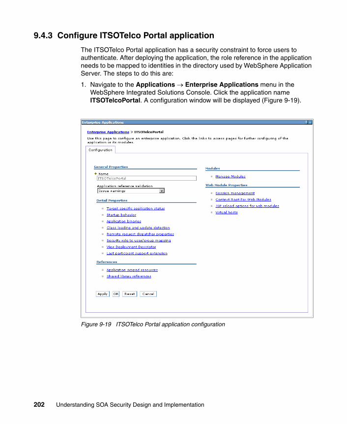
9.4.3 Configure ITSOTelco Portal application
The ITSOTelco Portal application has a security constraint to force users to authenticate. After deploying the application, the role reference in the application needs to be mapped to identities in the directory used by WebSphere Application Server. The steps to do this are:
1. Navigate to the Applications → Enterprise Applications menu in the WebSphere Integrated Solutions Console. Click the application name ITSOTelcoPortal. A configuration window will be displayed (Figure 9-19).
Figure 9-19 ITSOTelco Portal application configuration
202 Understanding SOA Security Design and Implementation

2. Click Security role to user/group mapping to edit the mapping between application roles and users and groups in the directory (Figure 9-20).
Figure 9-20 Mapping application roles to users and groups
3. Select the All authenticated? check box next to the ITSOBankers role, and click OK.
4. Save these changes to the master configuration.
9.5 Configure Federated Identity Manager for ITSOTelco
Now we need to configure the identity mediation for the ITSOTelco Portal application.
In the ITSOTelco Portal, the Federated Identity Manager WSSM Token Generator is used to inject a signed SAML 2.0 assertion into outbound Web service requests to ITSOBank. The configuration of the corresponding trust chain in the Federated Identity Manager instance at ITSOTelco is described in this section.
The steps to configure the identity mediation for the ITSOTelco Portal application are:
1. Log on to the Integrated Solutions Console, which hosts the Federated Identity Manager Console.
Note: The trust chain is created directly in the Federated Identity Manager Management Console, and tools, such as wsdl2tfim, are not used. This is to give you a stronger appreciation for what is happening in Federated Identity Manager.
Chapter 9. Technical implementation 203

2. Navigate to the Configure Trust Service → Trust Service Chains menu.
3. Create a new trust service chain with the properties in Table 9-4.
Table 9-4 Trust service chain properties
Property Value
Name outbound-to-itsobank
Request Type Validate
Applies To REGEXP:(.*/routerProject/services/AccountJCA.*)
Issuer urn:itfim:wssm:tokengenerator
204 Understanding SOA Security Design and Implementation

This trust service chain is shown in Figure 9-21. Note that the values for the Applies To and Issuer addresses will match the values automatically used by Federated Identity Manager’s WSSM Token Generator that was configured into the ITSOTelco Portal application in 9.3, “Add Web services security to the ITSOTelco Portal application” on page 184.
Figure 9-21 Trust chain properties
Chapter 9. Technical implementation 205

4. Add trust service module instances to the trust service chain as shown in Figure 9-22. Be sure to match the module instance types and the modes with those shown in the figure.
Figure 9-22 Module chain
5. When configuring the trust chain properties for the SAML 1.1 module, ensure that the Enable Signature Validation check box is unchecked (Figure 9-23), because the Federated Identity Manager WSSM Token Generator does not sign the SAML 1.1 assertion that it sends to Federated Identity Manager.
Figure 9-23 SAML 1.1 module properties
206 Understanding SOA Security Design and Implementation

6. The mapping rule for this trust chain can be found in the file saml11-saml20.xsl in the downloadable files that accompany this IBM Redbooks publication (see Appendix D, “Additional material” on page 461). Its contents are shown in Example 9-1.
Example 9-1 Mapping rule to convert from SAML 1.1 to SAML 2.0
<xsl:stylesheet xmlns:xsl="http://www.w3.org/1999/XSL/Transform" xmlns:stsuuser="urn:ibm:names:ITFIM:1.0:stsuuser" version="1.0">
<xsl:strip-space elements="*" /> <xsl:output method="xml" version="1.0" encoding="utf-8" indent="yes" />
<!-- Initially we start with a copy of the document. --> <xsl:template match="@* | node()"> <xsl:copy> <xsl:apply-templates select="@* | node()" /> </xsl:copy> </xsl:template>
<xsl:template match="//stsuuser:Principal"> <stsuuser:Principal> <stsuuser:Attribute name="name" type="urn:oasis:names:tc:SAML:2.0:nameid-format:unspecified"> <stsuuser:Value> <xsl:value-of select="//stsuuser:Principal/stsuuser:Attribute[@name='name']/stsuuser:Value" /> </stsuuser:Value> </stsuuser:Attribute> </stsuuser:Principal> </xsl:template>
<xsl:template match="//stsuuser:AttributeList"> <stsuuser:AttributeList> <!-- The authentcation method attribute --> <stsuuser:Attribute name="AuthenticationMethod" type="urn:oasis:names:tc:SAML:2.0:assertion"> <stsuuser:Value>urn:oasis:names:tc:SAML:2.0:am:password</stsuuser:Value> </stsuuser:Attribute> </stsuuser:AttributeList> </xsl:template>
</xsl:stylesheet>
The principal name is taken directly from the SAML 1.1 assertion data, with just the XML namespace of the attribute updated in its SAML 2.0 representation.
An AuthenticationMethod attribute is also added to the SAML 2.0 assertion, with the literal value “urn:oasis:names:tc:SAML:2.0:am:password”.
When loaded into the trust chain, the mapping rule will resemble what is shown in Figure 9-24 on page 208.
Chapter 9. Technical implementation 207

Figure 9-24 Map module properties
208 Understanding SOA Security Design and Implementation

7. When configuring the trust chain properties for the SAML 2.0 module (see Figure 9-25 for an example), follow these settings:
– Use ITSOTelco as the name of the organization issuing these SAML assertions.
– Sign the SAML assertions with a key. The key must be loaded into the Federated Identity Manager Key Service prior to creating the trust module chain.
– Encrypting assertion elements is not required.
Figure 9-25 SAML 2.0 module properties
8. After saving the trust module chain, the WebSphere Application Server instance running the Federated Identity Manager runtime needs to be restarted.
Chapter 9. Technical implementation 209
9.6 Configure XML firewall
In the ITSO lab environment, a DataPower XS40 appliance was used. You can also implement the solution presented here with a DataPower XI50.
9.6.1 Infrastructure configuration
We assume that the following steps have been successfully completed on the DataPower SOA appliance:
� Basic configuration has been performed on the device so that it is available in the network.
� An administrative domain has been created.
� Administrator credentials have been created for the administrative domain in the preceding step.
9.6.2 Add XML firewall
The configuration paradigm with the DataPower appliances allows dependent objects, such as files, policy, SSL configuration, and Federated Identity Manager configuration, to be added dynamically during the configuration of the XML Firewall. This is quite convenient and does not require interrupting a configuration process if a dependency was forgotten or not recognized before commencing a particular configuration exercise.
The steps to add the XML firewall are:
1. Log on to the administrative domain using administrator credentials. The Control Panel is displayed (Figure 9-26 on page 211).
210 Understanding SOA Security Design and Implementation
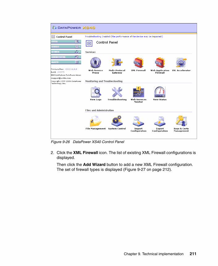
Figure 9-26 DataPower XS40 Control Panel
2. Click the XML Firewall icon. The list of existing XML Firewall configurations is displayed.
Then click the Add Wizard button to add a new XML Firewall configuration. The set of firewall types is displayed (Figure 9-27 on page 212).
Chapter 9. Technical implementation 211

Figure 9-27 Selecting the Firewall Wizard type
3. Choose Access Control (AAA) and click Next. The XML Firewall Service Name window is displayed (Figure 9-28).
Figure 9-28 Choosing a firewall name
212 Understanding SOA Security Design and Implementation

4. Type a name for the firewall, and click Next. The window to select the firewall service type is shown (Figure 9-29).
Figure 9-29 Selecting the firewall service type
5. In some cases, the XS40 can run the Web service implementation itself (this is called loopback mode). In this case, the Web service runs in WebSphere Application Server, so accept the default value of static-backend (Figure 9-29) and click Next.
Chapter 9. Technical implementation 213

The window to identify the location of the Web service (back end) is displayed (Figure 9-30).
Figure 9-30 Specifying the location of the Web service implementation
6. Enter the IP address and port of the WebSphere Application Server instance that runs the ITSOBanker2007 application. If DNS or static host entries are configured on the XS40, then the host name can be used instead of an IP address.
214 Understanding SOA Security Design and Implementation

Click Next. The window to enter front-end information is displayed (Figure 9-31).
Figure 9-31 Specifying front-end (client) configuration
7. This window allows the administrator to specify the IP address and port on the XS40 that listens for incoming Web service requests from clients. The values for this implementation are shown in Figure 9-31.
This window also provides the option to enable SSL on this listener. In this implementation, SSL is to be enabled between clients and the XS40, so select on. The window is updated to show the SSL Server Crypto Profile entry field. SSL configuration data has not been provided yet, but it can be done now. Click the + button to add the new SSL configuration at this time.
Chapter 9. Technical implementation 215

A new window (or tab) is displayed in the browser (Figure 9-32).
Figure 9-32 Configuring SSL settings
8. The first step in SSL configuration is to upload the private key. In Figure 9-32, under the Server Credentials section, select Upload to the right of Server Private Key.
216 Understanding SOA Security Design and Implementation

9. A new window in the browser displays the File Management window (Figure 9-33). Click the radio button to the left of Java Key Store, because the key pair for the SSL listener is in JKS format (see 9.2.2, “Key stores” on page 183). A new window in the browser is displayed and shows the Java console. Accept any warnings from the browser if they appear1.
Figure 9-33 File management window for uploading keys and certificates
10.After this Java console window has been displayed, enter the location of the Java key store containing the key pair for the XS40’s SSL listener in the File Management window (Figure 9-33). In this implementation, that is the itsobank-ssl.jks file.
Enter the Key store password, itso in this example, and click Refresh. This attempts to open the key store and enumerate the keys and certificates within the key store (Figure 9-34 on page 218).
1 Microsoft Internet Explorer® is required for this operation, using Sun™ JRE™ 1.4.2 or higher.
Chapter 9. Technical implementation 217

Figure 9-34 Selecting the private key
11.On Figure 9-34, from the Key to upload drop-down list, select the key itsobank-https (key). Enter the password to access this key from the key store, which is also itso in this implementation. The Save as name is automatically generated. Accept the default and click Upload to extract the key from the key store and load onto the XS40. A confirmation window is displayed. Click Continue to close this window. The File Management window also closes.
Navigate back to the Configure Server Side SSL window (Figure 9-32 on page 216). The private key location is populated.
Now, click the Upload button for the Server Certificate. The File Management window appears again (Figure 9-35 on page 219).
218 Understanding SOA Security Design and Implementation

Figure 9-35 Selecting the certificate for the SSL listener
12.Repeat the process above to upload the corresponding certificate for the private key. Use the same key store and passwords, but this time upload the key with the label itsobank-https (certificate) CN=https, O=itsobank, C=US.
Click Upload to extract the certificate from the key store and load onto the XS40. A confirmation window is displayed. Click Continue to close this window. The File Management window also closes.
Chapter 9. Technical implementation 219

Navigate back to the Configure Server Side SSL window (Figure 9-36). The certificate location is now populated.
Figure 9-36 Completed SSL settings
13.Protect the private key and certificate by choosing passwords and entering them in the Private Key Password and Server Certificate Password fields, and their corresponding Confirm Password fields.
Enter a Profile Name for this configuration. For example, itsobank-client-ssl is shown in Figure 9-36.
220 Understanding SOA Security Design and Implementation

14.Click Apply to save these settings and return to the Front End (Client) configuration window (Figure 9-37).
Figure 9-37 SSL settings populated on Front End (Client) window
15.The SSL Server Crypto Profile is now populated. Click Next to proceed to the Create an AAA Firewall Service window (Figure 9-38).
Figure 9-38 AAA Information
16.An existing AAA policy can be chosen at this time if one exists. In our case, a new policy is created by clicking the + button in Figure 9-38.
Chapter 9. Technical implementation 221

17.A window pops up to begin the AAA policy configuration. First, a prompt is displayed to solicit the name of the new policy (Figure 9-39).
Figure 9-39 Specifying the AAA policy name
Enter a name for the AAA policy. In this example, itsobank-account-policy is chosen. Click Create.
222 Understanding SOA Security Design and Implementation

The identity extraction window is displayed (Figure 9-40).
Figure 9-40 Identity extraction policy settings
18.Select the check boxes for Name from SAML Attribute Assertion and Name from SAML Authentication Assertion and click Next.
Chapter 9. Technical implementation 223

A new window is displayed where the authentication method is specified (Figure 9-41).
Figure 9-41 Authentication method
Recall that the ITSOTelco Portal sends a signed SAML 2.0 assertion in the WS-Security headers with the request. This assertion is used to authenticate the user and extract their identity by the XML firewall, prior to Federated Identity Manager being invoked to transform the identity in a post-processing step.
19.In Figure 9-41, select Accept a SAML Assertion with a Valid Signature.
224 Understanding SOA Security Design and Implementation
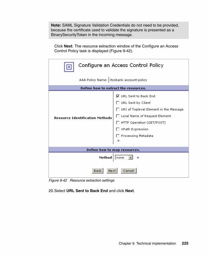
Click Next. The resource extraction window of the Configure an Access Control Policy task is displayed (Figure 9-42).
Figure 9-42 Resource extraction settings
20.Select URL Sent to Back End and click Next.
Note: SAML Signature Validation Credentials do not need to be provided, because the certificate used to validate the signature is presented as a BinarySecurityToken in the incoming message.
Chapter 9. Technical implementation 225

The request authorization window is displayed (Figure 9-43).
Figure 9-43 Request authorization settings
21.The XS40’s native authorization options are not used in this solution. At this time, choose Allow Any Authenticated Client and click Next.
226 Understanding SOA Security Design and Implementation

The post processing settings are displayed (Figure 9-44). This is where the integration with Federated Identity Manager is configured.
Figure 9-44 Post processing settings
22.Select the on radio button next to Request TFIM Token Mapping. Additional Federated Identity Manager configuration options are displayed.
Chapter 9. Technical implementation 227

Select the preserve option from the Replacement Method drop-down list. This is important; otherwise, the BinarySecurityToken containing the certificate for the message signature is stripped from the WS-Security headers. A later XSL transform in the firewall policy strips the original, incoming SAML 2.0 assertion from the outbound message.
No Federated Identity Manager configuration settings exist yet, but they can be added at this point by clicking the + button next to TFIM Configuration.
The configuration settings window for Tivoli Federated Identity Manager is displayed (Figure 9-45).
Figure 9-45 Federated Identity Manager configuration settings
23.Specify the location of the Federated Identity Manager Security Token Service by entering values for the Server Address and Port.
Enter values for the Applies-To Address, Issuer, Port Type, and Operation as shown in Figure 9-45. These settings are used to match a trust chain in the Federated Identity Manager Security Token Service. The full value of the Applies-To Address parameter is:
https://fw.itsobank.com:8000/routerProject/services/AccountJCA
Click Apply to close the Federated Identity Manager configuration settings window and return to the post processing settings.
228 Understanding SOA Security Design and Implementation

24.Click Commit to save the completed AAA policy. A confirmation window similar to Figure 9-46 is displayed.
Figure 9-46 Successful AAA policy creation
25.Click Done to return to the AAA Information window. The newly created AAA policy is now created (Figure 9-47).
Figure 9-47 AAA policy in place
Chapter 9. Technical implementation 229

26.Click Next to proceed to the final confirmation window for creating the XML firewall (Figure 9-48).
Figure 9-48 Confirmation window
27.Review the selections and then click Commit. Confirmation of successful creation is displayed as shown in Figure 9-49.
Figure 9-49 Successful creation of XML firewall
Click Done. The Configure XML Firewall window is displayed (Figure 9-50 on page 231).
230 Understanding SOA Security Design and Implementation

Figure 9-50 XML Firewall configuration window
As described earlier in this section, the preserve mode was used for the Federated Identity Manager identity mediation, so that the X.509 message signing token is not inadvertently removed. A side effect of this is that the SAML 2.0 assertion from the incoming message remains in the message, which is not
Chapter 9. Technical implementation 231

desirable. An additional Transform action needs to be added to the firewall policy to remove the SAML 2.0 assertion before the message is sent to the back end.
28.Click the ellipsis “...” next to the itsobank-aaa firewall policy to edit the policy. The firewall policy configuration window pops up (Figure 9-51).
Figure 9-51 Firewall policy configuration window
29.With the Request Rule selected at the bottom of this window, drag a transform action onto the processing line between the AAA policy and Results actions. As the transform is initially not configured, it is highlighted (Figure 9-52 on page 233).
232 Understanding SOA Security Design and Implementation

Figure 9-52 Adding a transform action
30.Double-click the new transform action to configure it. The configuration dialog pops up in a new window (Figure 9-53 on page 234).
Chapter 9. Technical implementation 233

Figure 9-53 Configuring the transform action
Transforms are represented in XSL. The XSL to remove the SAML 2.0 assertion from the message has been created in a file named remove-saml20.xsl. Its content is shown in Example 9-2.
Example 9-2 remove-saml20.xsl
<?xml version="1.0" encoding="UTF-8"?><xsl:stylesheet xmlns:xsl="http://www.w3.org/1999/XSL/Transform" version="1.0" xmlns:xalan="http://xml.apache.org/xslt" xmlns:soapenv="http://schemas.xmlsoap.org/soap/envelope/" xmlns:wsse="http://docs.oasis-open.org/wss/2004/01/oasis-200401-wss-wssecurity-secext-1.0.xsd" xmlns:saml="urn:oasis:names:tc:SAML:2.0:assertion"> <xsl:template match="@* | node()">
<xsl:copy><xsl:apply-templates select="@* | node()" />
</xsl:copy></xsl:template>
<xsl:template match="saml:Assertion" /> </xsl:stylesheet>
234 Understanding SOA Security Design and Implementation

The transform takes a copy of the incoming XML document (the request after post-processing with Federated Identity Manager) with the first template in the file and then removes the SAML 2.0 assertion with the second template.
Click Upload on Figure 9-53 on page 234. The File Management window pops up (Figure 9-54).
Figure 9-54 Locating the XSL transform file
31.Click Browse and locate the remove-saml20.xsl file. Click Upload to upload this file to the XS40 device.
A message confirmation about the successful upload is displayed (Figure 9-55).
Figure 9-55 Successful file upload
32.Click Continue to close this window and return to the window for configuring the XSL transform in the firewall policy. The Processing Control File is now populated (Figure 9-56 on page 236).
Chapter 9. Technical implementation 235

Figure 9-56 Processing control file populated
33.Click Done to return to the XML Firewall Policy configuration window (Figure 9-57 on page 237).
236 Understanding SOA Security Design and Implementation

Figure 9-57 XML Firewall Policy configuration window
34.Click Apply to save these changes, then click Close to return to the XML Firewall Configuration window (Figure 9-50 on page 231).
35.Click Apply on Figure 9-50 on page 231 to save the overall firewall configuration.
36.Click Save Config to ensure that the configuration changes are saved to the XS40 device’s startup configuration. This concludes the configuration of the XML Firewall in the DataPower XS40 device.
9.7 Add Web services security to the ITSOBanker2007 application
The ITSOBanker2007 application needs to be modified to enable message protection and integration with Tivoli Federated Identity Manager for identity mediation. You perform these steps using IBM Rational Application Developer 7.0 by editing the deployment description for the AccountJCAService Web service, located under the JSR-109 Web Services then Services container in the Project Explorer (Figure 9-58 on page 238).
Chapter 9. Technical implementation 237

Figure 9-58 Deployment descriptor for AccountJCA Web service
9.7.1 Configure request consumer
The request consumer needs to be configured to validate the signature on the body of incoming messages and to use the Federated Identity Manager WSSM Token Consumer to validate the incoming SAML 1.1 security token and convert it to a SAML 2.0 token for the login to WebSphere Application Server. The steps to configure the request consumer are:
1. Navigate to the Extension tab of the deployment descriptor. Expand the Request Consumer Service Configuration Details section.
Add a new requirement for message integrity on the body of the message (Figure 9-59 on page 239).
238 Understanding SOA Security Design and Implementation

Figure 9-59 Requirement for integrity of the message body
2. Add a new Security Token (Figure 9-60). The SAML 1.1 security token is specified here, because this is the token type expected in the incoming message. Click OK.
Figure 9-60 Required SAML 1.1 security token
Chapter 9. Technical implementation 239

3. Add a new Caller part (Figure 9-61). Notice that the caller part is for SAML 2.0, which is the token type returned by the Federated Identity Manager Security Token Service. The properties at the bottom of this window reference a SAML 1.1 token type, which indicates what token type is consumed in order to produce the token type specified in the caller part.
Figure 9-61 SAML 2.0 caller part
4. Navigate to the Binding Configurations tab and open the Request Consumer Binding Configuration Details section.
Create a new Trust Anchor (Figure 9-62 on page 241). Click OK.
240 Understanding SOA Security Design and Implementation

Figure 9-62 Trust anchor
Chapter 9. Technical implementation 241

5. Add a token consumer for the SAML 1.1 security token expected in the requests (Figure 9-63).
Figure 9-63 SAML 1.1 token consumer
242 Understanding SOA Security Design and Implementation
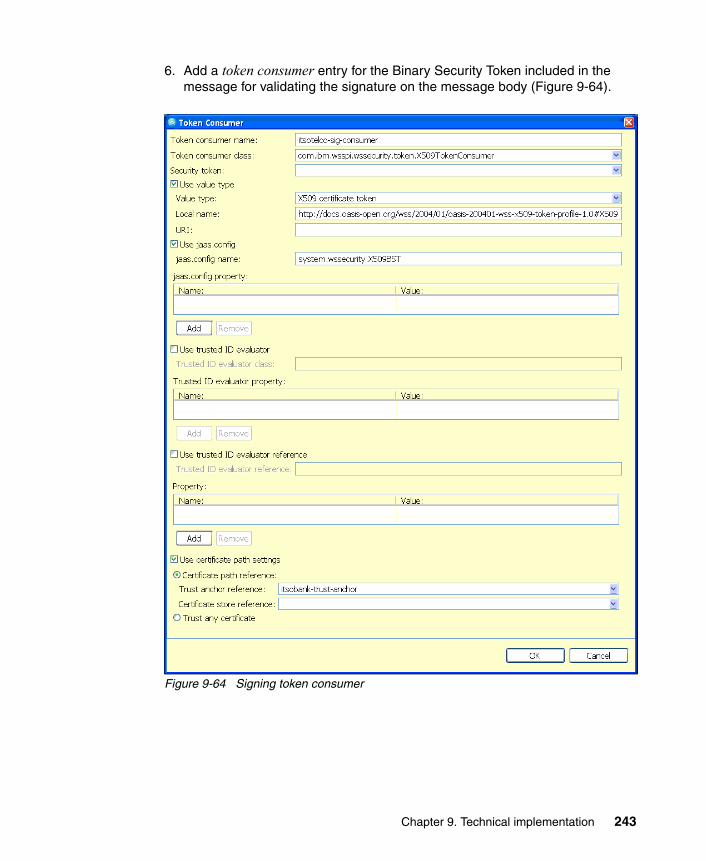
6. Add a token consumer entry for the Binary Security Token included in the message for validating the signature on the message body (Figure 9-64).
Figure 9-64 Signing token consumer
Chapter 9. Technical implementation 243

7. Add a Key Locator to specify the public key used to verify message signatures (Figure 9-65).
Figure 9-65 Key locator for signing key
244 Understanding SOA Security Design and Implementation

8. Add a Key Information entry to associate the key location and signing security token definitions (Figure 9-66).
Figure 9-66 Key information for signing key
Chapter 9. Technical implementation 245
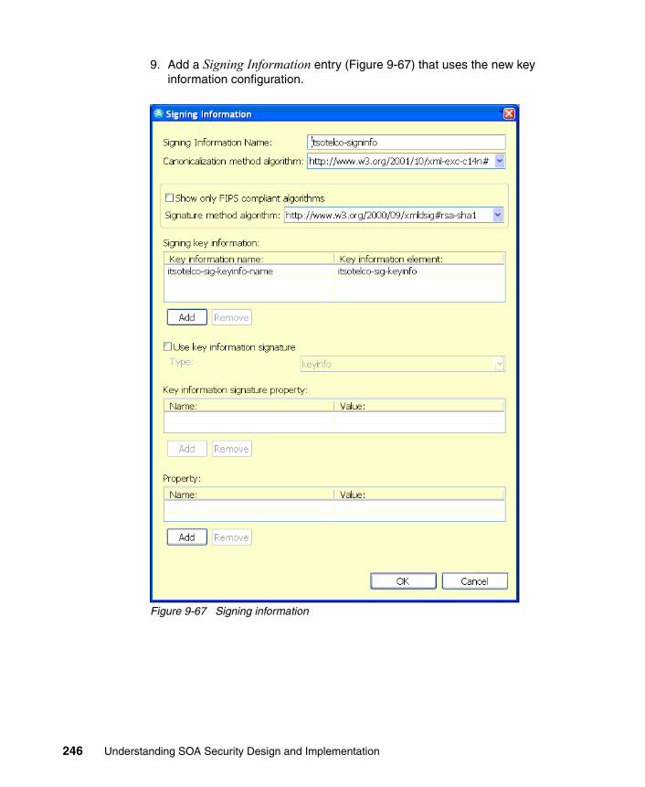
9. Add a Signing Information entry (Figure 9-67) that uses the new key information configuration.
Figure 9-67 Signing information
246 Understanding SOA Security Design and Implementation

10.With the new signing information selected, add a new Part Reference (Figure 9-68).
Figure 9-68 Part Reference
11.With the new part reference selected, add a new Transform (Figure 9-69).
Figure 9-69 Transform
The request consumer configuration is complete.
9.7.2 Configure response generator
This section explains the configuration steps to sign the responses from the Web service:
1. Navigate to the Extensions tab in the deployment descriptor.
Chapter 9. Technical implementation 247

Expand the Response Generator Service Configuration Details then click Integrity.
2. Add an Integrity requirement (Figure 9-70).
Figure 9-70 Message body integrity requirement
3. Navigate to the Binding Configurations tab.
Expand the Response Generator Binding Configuration Details then click Token Generator.
248 Understanding SOA Security Design and Implementation

4. Add a Token Generator for the response signing token (Figure 9-71).
Figure 9-71 Token generator for signing token
Chapter 9. Technical implementation 249

5. Add a Key Locator to specify the location of the signing key to be used by the token generator (Figure 9-72).
Figure 9-72 Key locator for message signing key
250 Understanding SOA Security Design and Implementation

6. Create a Key Information entry to associate the signing token and key locator definitions (Figure 9-73).
Figure 9-73 Key information for message signing key
Chapter 9. Technical implementation 251
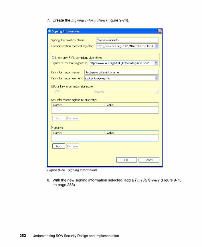
7. Create the Signing Information (Figure 9-74).
Figure 9-74 Signing information
8. With the new signing information selected, add a Part Reference (Figure 9-75 on page 253).
252 Understanding SOA Security Design and Implementation

Figure 9-75 Part reference
9. With the new part reference selected, add a new Transform (Figure 9-76).
Figure 9-76 Transform
Configuration of the response generation is complete.
9.8 Deploy ITSOBanker2007 application
In order to deploy the ITSOBanker2007 application, we first need to configure some infrastructure components. Then, we install the CICS ECI resource adapter and configure the CICS Connection® Factory on the EIS system. Next, we have to configure a JAAS login module and then we can install the ITSOBanker2007 application.
Chapter 9. Technical implementation 253
9.8.1 Infrastructure configuration
The WebSphere Application Server profile in which the ITSOTelco Portal is deployed has the following configuration already completed:
� Administrative and application security bas been configured. In the ITSO lab environment, a Tivoli Directory Server instance was shared with Access Manager for e-business and Federated Identity Manager for this purpose.
� Prerequisite steps for using the Web Services Security Management component of Tivoli Federated Identity Manager have been completed, following the instructions in the IBM Tivoli Federated Identity Manager Web Services Security Management Guide Version 6.1.1, GC32-0169-01, in the Tivoli Federated Identity Manager product documentation set:
– The ITFIM_WSSM variable was created.
– The ITFIM_WSSM shared library definition was created.
– The class loader for the WebSphere Application Server instance to be used by the ITSOTelco Portal has been configured to use the ITFIM_WSSM shared library definition.
– A JAAS system login module, itfim.wssm.samla, is configured.
� The itsobank.jks key store has been uploaded to the application server instance’s home directory, for example, /opt/IBM/WebSphere/AppServer/profiles/itsobank.
9.8.2 Installing the CICS ECI resource adapter
The ITSOBanker2007 application requires a connection to a CICS Transaction Gateway using a Java Connector Architecture (JCA) resource adapter. Resource adapters are installed into application servers by adding the contents of a Resource Adapter Module (represented by a file with an extension of .rar) to the application server. A RAR file contains a collection of JAR files and a deployment descriptor (ra.xml) that describes the deployment properties of the resource adapter.
This section assumes that the CICS Transaction Gateway is already installed on a z/OS machine and that the CICS resource adapter (cicseci.rar) shipped with the CICS Transaction Gateway for z/OS is available.
254 Understanding SOA Security Design and Implementation

The steps to install the CICS ECI resource adapter are:
1. Log on to the WebSphere Application Server Administrative Console. Navigate to Resources and then Resource Adapters. Keeping the scope at the node level, click Install RAR. The Install RAR File window is displayed (Figure 9-77).
Figure 9-77 Specifying the rar file location
2. Click Browse to navigate to the location of the cicseci602.rar file and select it. Click Next.
The RAR file is uploaded to WebSphere Application Server, and then the properties window is displayed (Figure 9-78 on page 256).
Chapter 9. Technical implementation 255
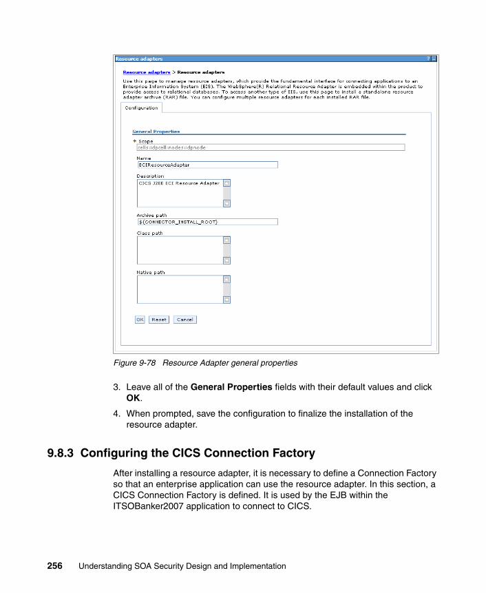
Figure 9-78 Resource Adapter general properties
3. Leave all of the General Properties fields with their default values and click OK.
4. When prompted, save the configuration to finalize the installation of the resource adapter.
9.8.3 Configuring the CICS Connection Factory
After installing a resource adapter, it is necessary to define a Connection Factory so that an enterprise application can use the resource adapter. In this section, a CICS Connection Factory is defined. It is used by the EJB within the ITSOBanker2007 application to connect to CICS.
256 Understanding SOA Security Design and Implementation

The following CICS Transaction Gateway configuration information is required:
� ConnectionURL� ServerName� PortNumber� TPNName
To configure the CICS Connection Factory:
1. In the Resource adapters view in the WebSphere Administration Console, click the ECIResourceAdapter created in 9.8.2, “Installing the CICS ECI resource adapter” on page 254. The general properties of the resource adapter are displayed (Figure 9-79).
Figure 9-79 Resource adapter general properties
Chapter 9. Technical implementation 257

2. Under the Additional Properties section, click J2C connection factories. The (currently empty) list of J2C connection factories is displayed (Figure 9-80).
Figure 9-80 J2C connection factories
3. Click New. The configuration window for a new J2C connection factory is displayed (Figure 9-81 on page 259).
258 Understanding SOA Security Design and Implementation

Figure 9-81 Creating a new CICS connection factory
4. Complete the Name and JNDI name fields by using the values provided in Table 9-5.
Table 9-5 CICS connection factory properties
Parameter Value
Name CICS Connection Factory
JNDI name eis/cicsConnectionFactory
Chapter 9. Technical implementation 259

5. Click Apply to save these values. Under Additional Properties, click the Custom Properties link. The Custom Properties configuration window is displayed (Figure 9-82).
Figure 9-82 Custom properties for CICS connection factory
6. At this point, specify the values for the CICS environment being used. In the ITSOBank environment, those custom properties are shown in Figure 9-82.
In this scenario, UserName and Password do not need to be specified, because that information is obtained from the Federated Identity Manager Security Token Service by a JAAS login module.
7. Click Save when finished to save these configuration changes to the master configuration.
9.8.4 Configure a JAAS login module
In this section, we describe how to configure a JAAS login module to get a RACF Passticket from the Tivoli Federated Identity Manager Security Token Service. This login module is invoked from the resource adapter described in the previous section.
The downloadable files accompanying this IBM Redbooks publication contain a JAAS login module in a collection of JAR files. These JAR files need to be copied into the <WAS_HOME>/lib directory so that they can be used by WebSphere Application Server.
260 Understanding SOA Security Design and Implementation

The commands used in the ITSOBank environment are shown in Example 9-3.
Example 9-3 Installing the JAAS login module
# cp soa-jaas-login-061017a.jar /opt/IBM/WebSphere/AppServer/lib# cp soa-wstrust-client-impl-061017a.jar /opt/IBM/WebSphere/AppServer/lib# cp soa-wstrust-client-intf-061017a.jar /opt/IBM/WebSphere/AppServer/lib# cp soa-common-061017a.jar /opt/IBM/WebSphere/AppServer/lib# chmod 644 /opt/IBM/WebSphere/AppServer/lib/*061017a.jar
To configure a JAAS login module:
1. Log on to the WebSphere Application Server Administrative Console, and navigate to Security, then click Secure administration, applications, and infrastructure. In the Authentication section, expand Java Authentication and Authorization Service. Click Application logins to display the current configuration. Click New to add a new configuration.
2. Provide a meaningful name for the alias, such as FIMforJCA, and click Apply in the dialog displayed in Figure 9-83.
Figure 9-83 JAAS Application login configuration
3. Under Additional Properties, click JAAS login modules.
4. Click New to create a new JAAS login module (Figure 9-84 on page 262). Use the values in Table 9-6 on page 262.
Important: Restart the WebSphere Application Server instance so that the new jar file is available.
Chapter 9. Technical implementation 261

Table 9-6 JAAS login module configuration
5. The JAAS login properties page should look like Figure 9-84. Click Apply to save this new configuration, and remain on this window.
Figure 9-84 JAAS login module properties
6. Under Additional Properties, click Custom properties and create the properties listed in Table 9-7. Modify the value of the stsendpoint parameter to be consistent with the Federated Identity Manager environment used.
Table 9-7 Custom properties for the JAAS login module
Parameter Value
Module class name com.tivoli.am.fim.jaas.login.loginmodules.FIMPrincipalMapper
Use login module proxy selected
Authentication strategy REQUIRED
Name Value
delegate com.tivoli.am.fim.jaas.login.loginmodules.FIMPrincipalMapper
appliesto ITSOBanker2007
cache_cleanup_interval 30
cache_expiration_interval 60
issuer urn:itfim:jaas
stsendpoint http://sts.itsobank.com:9080/TrustServer/SecurityTokenService
262 Understanding SOA Security Design and Implementation

7. Click Save to complete the configuration of the JAAS login module.
9.8.5 Install the ITSOBanker2007 application
Install the ITSOBanker enterprise application (ITSOBanker2007.ear) using the WebSphere Integrated Solutions Console. Accept all defaults when deploying the application.
During the installation, the Map resource references to resources window is shown (Figure 9-85).
Figure 9-85 Before resource references are mapped
Chapter 9. Technical implementation 263

The references to the CICS JCA adapter in the application need to be mapped to the CICS JCA adapter configured in 9.8.3, “Configuring the CICS Connection Factory” on page 256.
To install the ITSOBanker enterprise application:
1. In the Specify authentication method section, select Use custom login configuration. Then, select the FIMforJCA application login configuration from the drop-down menu.
2. Enter the Target Resource JNDI Name. The value must be eis/cicsConnectionFactory to match the value chosen in 9.8.3, “Configuring the CICS Connection Factory” on page 256.
3. Select the check box next to the AccountEJB module at the bottom of the window. Click Apply beneath where the FIMforJCA application login configuration was chosen.
Successful completion of these steps is shown in Figure 9-86 on page 265.
264 Understanding SOA Security Design and Implementation

Figure 9-86 After resource references are mapped
4. Complete the installation of the application by accepting defaults.
5. Save the master configuration after the application is installed.
9.9 Configure Federated Identity Manager for ITSOBank
Our final task before we can test the solution is to configure Federated Identity Manager.
Chapter 9. Technical implementation 265

9.9.1 Identity mediation for XML firewall
In the DataPower XS40 appliance at ITSOBank, the integration with Federated Identity Manager is used to map the incoming SAML 2.0 assertion (ITSOBank’s standard for working with partners) to a SAML 1.1 assertion (ITSOBank’s standard for internal use). The configuration of the corresponding trust chain in the Federated Identity Manager instance at ITSOBank is described in this section.
To configure the trust chain in the Federated Identity Manager instance at ITSOBank:
1. Log on to the Integrated Solutions Console, which hosts the Federated Identity Manager Console.
2. Navigate to the Configure Trust Service then click Trust Service Chains menu. Create a new trust service chain with the properties in Table 9-8.
Table 9-8 Properties for the new trust service chain
This trust service chain is shown in Figure 9-87 on page 267. Note that the values for the Applies To and Issuer addresses match the values chosen when configuring the DataPower/Federated Identity Manager integration in 9.6, “Configure XML firewall” on page 210.
Note: The trust chain is created directly in the Federated Identity Manager Management Console, and tools, such as wsdl2tfim, are not used. This is to give you a stronger appreciation for what is happening in Federated Identity Manager.
Property Value
Name inbound-to-dp
Request Type Validate
Applies To REGEXP:(.*/routerProject/services/AccountJCA.*)
Issuer urn:dp:itfim
266 Understanding SOA Security Design and Implementation

Figure 9-87 Trust service chain properties
Chapter 9. Technical implementation 267
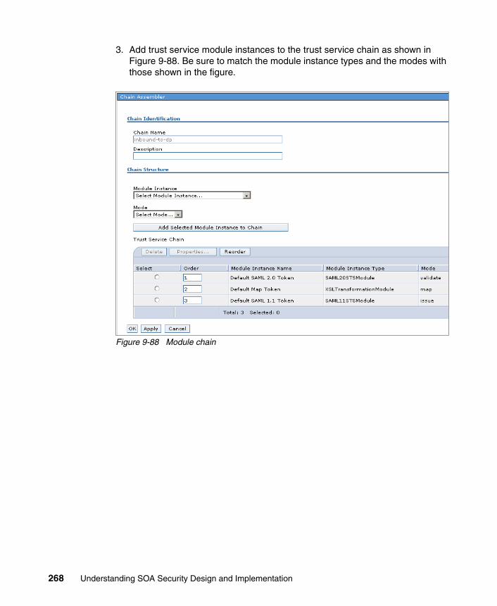
3. Add trust service module instances to the trust service chain as shown in Figure 9-88. Be sure to match the module instance types and the modes with those shown in the figure.
Figure 9-88 Module chain
268 Understanding SOA Security Design and Implementation

4. When configuring the trust chain properties for the SAML 2.0 module, ensure that the Enable Signature Validation check box is checked (Figure 9-89).
Figure 9-89 SAML 2.0 module properties
The mapping rule for this trust chain can be found in the file saml20-saml11.xsl in the downloadable files that accompany this book. Its content is shown in Example 9-4.
Example 9-4 Mapping rule to convert from SAML 2.0 to SAML 1.1
<xsl:stylesheet xmlns:xsl="http://www.w3.org/1999/XSL/Transform" xmlns:stsuuser="urn:ibm:names:ITFIM:1.0:stsuuser" version="1.0">
<xsl:strip-space elements="*" /> <xsl:output method="xml" version="1.0" encoding="utf-8" indent="yes" />
<!-- Initially we start with a copy of the document. --> <xsl:template match="@* | node()"> <xsl:copy> <xsl:apply-templates select="@* | node()" /> </xsl:copy> </xsl:template>
<xsl:template match="//stsuuser:Principal">
Chapter 9. Technical implementation 269

<stsuuser:Principal> <stsuuser:Attribute name="name" type="urn:oasis:names:tc:SAML:1.0:nameid-format:unspecified"> <stsuuser:Value> <xsl:value-of select="//stsuuser:Principal/stsuuser:Attribute[@name='name']/stsuuser:Value" /> </stsuuser:Value> </stsuuser:Attribute> </stsuuser:Principal> </xsl:template>
<xsl:template match="//stsuuser:AttributeList"> <stsuuser:AttributeList> <!-- The authentcation method attribute --> <stsuuser:Attribute name="AuthenticationMethod" type="urn:oasis:names:tc:SAML:1.0:assertion"> <stsuuser:Value>urn:oasis:names:tc:SAML:1.0:am:password</stsuuser:Value> </stsuuser:Attribute> </stsuuser:AttributeList> </xsl:template>
</xsl:stylesheet>
The principal name is taken directly from the SAML 2.0 assertion data with just the XML namespace of the attribute updated in its SAML 1.1 representation.
An AuthenticationMethod attribute is also added to the SAML 1.1 assertion with the literal value “urn:oasis:names:tc:SAML:1.0:am:password”.
270 Understanding SOA Security Design and Implementation

When loaded into the trust chain, the mapping rule resembles what is shown in Figure 9-90.
Figure 9-90 Map module properties
Chapter 9. Technical implementation 271

5. When configuring the trust chain properties for the SAML 1.1 module (see Figure 9-91 for an example):
– Use ITSOBank as the name of the organization issuing the SAML assertions.
– Signing the SAML assertion is not required.
Figure 9-91 SAML 1.1 module properties
9.9.2 Identity mediation for ITSOBanker2007 application
In the ITSOBanker2007 application, the Federated Identity Manager WSSM Token Consumer is used to authenticate the incoming SAML 1.1 assertion and use the Federated Identity Manager STS to map it to a SAML 2.0 assertion, which is used to set the user’s identity in WebSphere Application Server. The configuration of the corresponding trust chain in the Federated Identity Manager instance at ITSOBank is described in this section.
Note: The trust chain is created directly in the Federated Identity Manager Management Console, and tools, such as wsdl2tfim, are not used. This is to give you a stronger appreciation for what is happening in Federated Identity Manager.
272 Understanding SOA Security Design and Implementation

To configure the corresponding trust chain in the Federated Identity Manager instance at ITSOBank:
1. Log on to the Integrated Solutions Console, which hosts the Federated Identity Manager Console.
2. Navigate to the Configure Trust Service and then click Trust Service Chains menu.
3. Create a new trust service chain with the properties in Table 9-9.
Table 9-9 Properties for new trust service chain
This trust service chain is shown in Figure 9-92 on page 274. Note that the values for the Applies To and Issuer addresses match the values automatically used by Federated Identity Manager’s WSSM Token Consumer that was configured into the ITSOBanker2007 application in 9.7, “Add Web services security to the ITSOBanker2007 application” on page 237.
Property Value
Name inbound-to-was
Request Type Validate
Applies To REGEXP:(.*/routerProject/services/AccountJCA)
Issuer urn:itfim:wssm:tokenconsumer
Chapter 9. Technical implementation 273
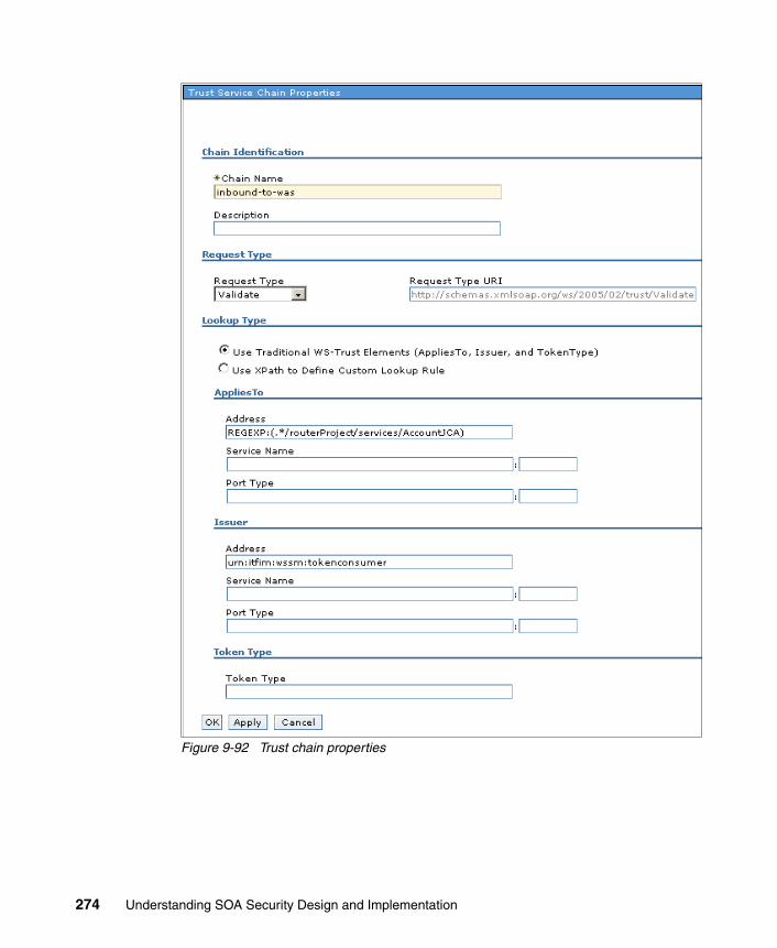
Figure 9-92 Trust chain properties
274 Understanding SOA Security Design and Implementation

4. Add trust service module instances to the trust service chain as shown in Figure 9-93. Be sure to match the module instance types and the modes with those shown in the figure.
Figure 9-93 Module chain
5. When configuring the trust chain properties for the SAML 1.1 module, ensure that the Enable Signature Validation check box is unchecked (Figure 9-94), because the SAML 1.1 assertion received from the DataPower XS40 is not signed.
Figure 9-94 SAML 1.1 module properties
Chapter 9. Technical implementation 275

The mapping rule for this trust chain can be found in the file saml11-saml20.xsl in the downloadable files that accompany this IBM Redbook. Its content is shown in Example 9-5.
Example 9-5 Mapping rule to convert from SAML 1.1 to SAML 2.0
<xsl:stylesheet xmlns:xsl="http://www.w3.org/1999/XSL/Transform" xmlns:stsuuser="urn:ibm:names:ITFIM:1.0:stsuuser" version="1.0">
<xsl:strip-space elements="*" /> <xsl:output method="xml" version="1.0" encoding="utf-8" indent="yes" />
<!-- Initially we start with a copy of the document. --> <xsl:template match="@* | node()"> <xsl:copy> <xsl:apply-templates select="@* | node()" /> </xsl:copy> </xsl:template>
<xsl:template match="//stsuuser:Principal"> <stsuuser:Principal> <stsuuser:Attribute name="name" type="urn:oasis:names:tc:SAML:2.0:nameid-format:unspecified"> <stsuuser:Value> <xsl:value-of select="//stsuuser:Principal/stsuuser:Attribute[@name='name']/stsuuser:Value" /> </stsuuser:Value> </stsuuser:Attribute> </stsuuser:Principal> </xsl:template>
<xsl:template match="//stsuuser:AttributeList"> <stsuuser:AttributeList> <!-- The authentcation method attribute --> <stsuuser:Attribute name="AuthenticationMethod" type="urn:oasis:names:tc:SAML:2.0:assertion"> <stsuuser:Value>urn:oasis:names:tc:SAML:2.0:am:password</stsuuser:Value> </stsuuser:Attribute> </stsuuser:AttributeList> </xsl:template>
</xsl:stylesheet>
The principal name is taken directly from the SAML 1.1 assertion data with just the XML namespace of the attribute updated in its SAML 2.0 representation.
An AuthenticationMethod attribute is also added to the SAML 2.0 assertion with the literal value “urn:oasis:names:tc:SAML:2.0:am:password”.
276 Understanding SOA Security Design and Implementation

When loaded into the trust chain, the mapping rule resembles what is shown in Figure 9-95.
Figure 9-95 Map module properties
6. When configuring the trust chain properties for the SAML 2.0 module (see Figure 9-96 on page 278 for an example):
– Use ITSOBank as the name of the organization issuing the SAML assertions.
– Signing the assertion is not required.
– Encrypting assertion elements is not required.
Chapter 9. Technical implementation 277

Figure 9-96 SAML 2.0 module properties
9.9.3 Deploy LDAP mapping module
In this section, we deploy the Lightweight Directory Access Protocol (LDAP) mapping module. This module is used to retrieve a user’s RACF user ID from an attribute in their LDAP user entry.
A Federated Identity Manager trust service module is provided in form of a JAR file. That JAR file contains runtime code (JAR), a module descriptor (XML), and a resource bundle used for the creation of the new configuration panel into the Federated Identity Manager console (JAR).
The steps to deploy the LDAP mapping module are:
7. From the <FIM_HOME>/plugins directory, unzip the LDAP module, ldap-sts-plugin-module-061017a.jar. This should create a new subdirectory named com.tivoli.am.fim.ldap.plugin_1.0.
278 Understanding SOA Security Design and Implementation

8. Copy the resource bundle soa-ldap-map-i18n.jar to the location of the installed Federated Identity Manager Management Console, for example:
/opt/IBM/WebSphere/AppServer/systemApps/isclite.ear/itfim-fimconsole-e.war/WEB-INF/lib
The addition of a new plug-in equates to a new version of the Federated Identity Manager runtime application. In order to redeploy the runtime through the Federated Identity Manager console, it is necessary to manually increment the serialId property in <FIM_HOME>/pkg/software.properties.
9. Increment the existing value for com.tivoli.am.fim.rte.software.serialId and optionally update the com.tivoli.am.fim.rte.software.displayName.
In the ITSO environment, the values were changed, as shown in Example 9-6.
Example 9-6 Increment the software serialId
From:com.tivoli.am.fim.rte.software.serialId=1184897266670com.tivoli.am.fim.rte.software.displayName=6.1.1.1 [070406a] To:com.tivoli.am.fim.rte.software.serialId= 1184897266671com.tivoli.am.fim.rte.software.displayName=6.1.1.1 [070406a-LDAP-STS]
10.Close any browser windows using the Federated Identity Manager console and restart the WebSphere Application Server instance so that the change can take effect.
11.Log on to the Federated Identity Manager console and browse to Domain Management and then click Runtime Node Management. The Management Console will have detected that a newer version of the Federated Identity Manager runtime is available (Figure 9-97 on page 280).
Important: On a non-Windows machine, ensure that the new subdirectory has file permissions 770 and the files have permissions 660. The subdirectory and the files should be owned by the user under which the WebSphere Application Server instance for the Federated Identity Manager Management Console executes.
Important: On a non-Windows machine, ensure that the file has permissions of 644.
Chapter 9. Technical implementation 279

Figure 9-97 Runtime deployment
12.Click Deploy Runtime to propagate the new version of the Federated Identity Manager runtime.
13.Restart WebSphere Application Server after deploying the new version of the Federated Identity Manager runtime.
9.9.4 Create LDAP mapping module instance
An instance of the Federated Identity Manager STS module for identity mapping using LDAP is required for 9.9.7, “Identity mediation for CICS connectivity” on page 284.
To create the LDAP mapping module instance:
1. Use the Federated Identity Manager Management Console and navigate to the Configure Trust Service and then click Module Instances. Click Create to create a new trust chain module instance.
280 Understanding SOA Security Design and Implementation

The Token Type selection window is displayed (Figure 9-98).
Figure 9-98 Selecting the LDAPSTSModule type
2. Select the LDAPSTSModule from the list and click Next.
3. On the next window, enter the name LDAP Map for the Module Instance Name and click Finish.
9.9.5 Create RACF passticket module instance
An instance of the Federated Identity Manager STS module for RACF passticket generation is required for 9.9.7, “Identity mediation for CICS connectivity” on page 284.
Chapter 9. Technical implementation 281
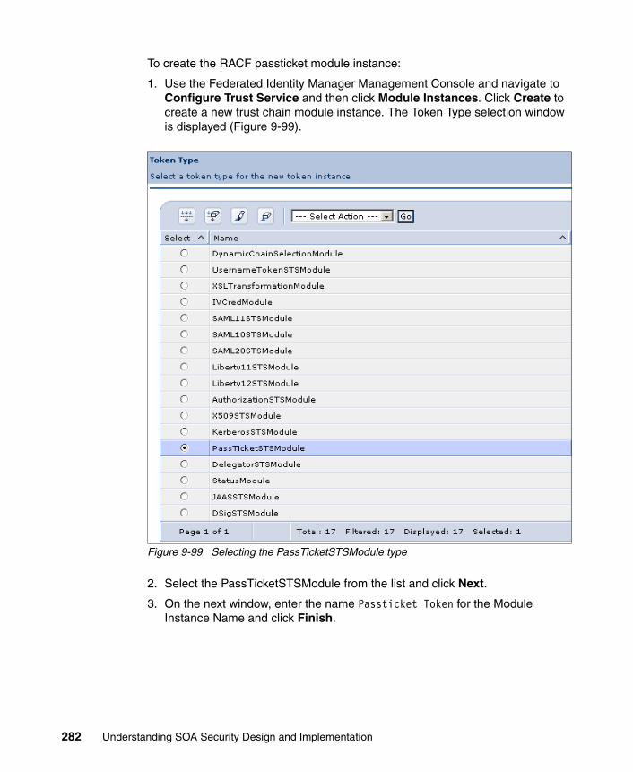
To create the RACF passticket module instance:
1. Use the Federated Identity Manager Management Console and navigate to Configure Trust Service and then click Module Instances. Click Create to create a new trust chain module instance. The Token Type selection window is displayed (Figure 9-99).
Figure 9-99 Selecting the PassTicketSTSModule type
2. Select the PassTicketSTSModule from the list and click Next.
3. On the next window, enter the name Passticket Token for the Module Instance Name and click Finish.
282 Understanding SOA Security Design and Implementation

9.9.6 Create Username token module instance
An instance of the Federated Identity Manager STS module for Username token is required for 9.9.7, “Identity mediation for CICS connectivity” on page 284.
To create the Username token module instance:
1. Use the Federated Identity Manager Management Console and navigate to Configure Trust Service and then click Module Instances. Click Create to create a new trust chain module instance. The Token Type selection window is displayed (Figure 9-100).
Figure 9-100 Selecting the UsernameTokenSTSModule type
2. Select the UsernameTokenSTSModule from the list and click Next.
Chapter 9. Technical implementation 283
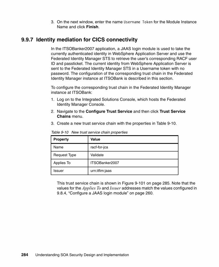
3. On the next window, enter the name Username Token for the Module Instance Name and click Finish.
9.9.7 Identity mediation for CICS connectivity
In the ITSOBanker2007 application, a JAAS login module is used to take the currently authenticated identity in WebSphere Application Server and use the Federated Identity Manager STS to retrieve the user’s corresponding RACF user ID and passticket. The current identity from WebSphere Application Server is sent to the Federated Identity Manager STS in a Username token with no password. The configuration of the corresponding trust chain in the Federated Identity Manager instance at ITSOBank is described in this section.
To configure the corresponding trust chain in the Federated Identity Manager instance at ITSOBank:
1. Log on to the Integrated Solutions Console, which hosts the Federated Identity Manager Console.
2. Navigate to the Configure Trust Service and then click Trust Service Chains menu.
3. Create a new trust service chain with the properties in Table 9-10.
Table 9-10 New trust service chain properties
This trust service chain is shown in Figure 9-101 on page 285. Note that the values for the Applies To and Issuer addresses match the values configured in 9.8.4, “Configure a JAAS login module” on page 260.
Property Value
Name racf-for-jca
Request Type Validate
Applies To ITSOBanker2007
Issuer urn:itfim:jaas
284 Understanding SOA Security Design and Implementation

Figure 9-101 Trust chain properties
Chapter 9. Technical implementation 285

4. Add trust service module instances to the trust service chain as shown in Figure 9-102. Be sure to match the module instance types and the modes with those shown in the figure.
Figure 9-102 Module chain
5. When configuring the trust chain properties for the Username token module, check the Skip password validation check box (Figure 9-103), because only a username is sent by the JAAS login module to the Federated Identity Manager STS.
Figure 9-103 Username token module properties
The LDAP mapping module works by locating a directory entry where the username from the trust chain matches a specified attribute of the directory entry. It then extracts the data from the mapping attribute from the same directory entry and uses that in further trust chain processing.
6. When configuring the LDAP mapping module (Figure 9-104 on page 287), the location of the LDAP server (host name and port), credentials for an
286 Understanding SOA Security Design and Implementation

administrative user (bind user and password) and its data (base DN, search attribute, and mapping attribute) need to be specified. The bind credentials need to be able to read attributes for directory entries beneath the base DN.
Figure 9-104 LDAP mapping module properties
Chapter 9. Technical implementation 287

7. When configuring the RACF passticket module (Figure 9-105), the Application Name and Passticket Key need to be specified. The values for these entries have to be obtained from the RACF system administrator who enabled passtickets for the CICS application.
Figure 9-105 Passticket module properties
9.9.8 Restart WebSphere Application Server
After successfully completing all configuration steps in 9.9, “Configure Federated Identity Manager for ITSOBank” on page 265, the WebSphere Application Server instance running the Federated Identity Manager Runtime must be restarted.
9.10 Testing the solution
Now it is time to test the implementation.
288 Understanding SOA Security Design and Implementation

9.10.1 Create the test user
To create the test user, follow these steps:
1. A user needs to be created in the ITSOTelco and ITSOBank systems. In this case, both organizations use Access Manager for e-business, so an Access Manager user can be created (Example 9-7) in both environments.
Example 9-7 Creating the itsoman user in Tivoli Access Manager (TAM)
pdadmin sec_master> user show itsomanLogin ID: itsomanLDAP DN: uid=itsoman,c=usLDAP CN: ITSO ManLDAP SN: ManDescription:Is SecUser: YesIs GSO user: NoAccount valid: YesPassword valid: Yes
2. On the ITSOBank side, the RACF user identity is stored in LDAP. The decision was made to use the uniqueIdentifier attribute, which is a member of the ePerson objectclass. Because the user was originally created through Access Manager, only the inetorgperson objectclass was used. The ldapmodify command can be used to add the ePerson objectclass to the user’s entry (Example 9-8).
Example 9-8 Adding the eperson objectclass
# idsldapmodify -D cn=root -w <password>dn: uid=itsoman,c=uschangetype: modifyreplace: objectclassobjectclass: inetorgpersonobjectclass: eperson
modifying entry uid=itsoman,c=us
3. Now, the uniqueIdentifier attribute can be added (Example 9-9). Its value should be the user’s RACF identity.
Example 9-9 Adding the uniqueIdentifier attribute
local:/opt/IBM/WebSphere/AppServer/profiles/idp/logs/idp # idsldapmodify -D cn=root -w passw0rddn: uid=itsoman,c=uschangetype: modify
Chapter 9. Technical implementation 289

add: uniqueIdentifieruniqueIdentifier: ITSOMAN1
modifying entry uid=itsoman,c=us
9.10.2 Access the application
Open a browser and access the ITSOTelco Portal application. The URL resembles:
http://portal.itsotelco.com/ITSOTelcoPortalWeb/index.jsp
Authenticate with the valid user, such as itsoman created in 9.10.1, “Create the test user” on page 289.
Figure 9-106 Logging on to the ITSOTelco Portal
Check the value of the Web Service URL parameter, and then click Get Balance. After successful execution of the application, the result should resemble Figure 9-107 on page 291.
290 Understanding SOA Security Design and Implementation

Figure 9-107 Successful retrieval of the balance from ITSOBank’s CICS system
9.10.3 Message traces
Let us examine some traces more closely.
Request from ITSOTelco Portal to DataPower XS40The initial request, shown in Example 9-10, carries a signed SAML 2.0 security token.
Example 9-10 Request from ITSOTelco Portal to DataPower XS40
<soapenv:Envelope xmlns:soapenv="http://schemas.xmlsoap.org/soap/envelope/" xmlns:soapenc="http://schemas.xmlsoap.org/soap/encoding/" xmlns:xsd="http://www.w3.org/2001/XMLSchema" xmlns:xsi="http://www.w3.org/2001/XMLSchema-instance" xmlns:wsa="http://www.w3.org/2005/08/addressing" xmlns:env="http://schemas.xmlsoap.org/soap/envelope/" xmlns:dp="http://www.datapower.com/schemas/management"> <soapenv:Header> <wsse:Security soapenv:mustUnderstand="1" xmlns:wsse="http://docs.oasis-open.org/wss/2004/01/oasis-200401-wss-wssecurity-secext-1.0.xsd"> <wsse:BinarySecurityToken EncodingType="http://docs.oasis-open.org/wss/2004/01/oasis-200401-wss-soap-message-security-1.0#Base64Binary" ValueType="http://docs.oasis-open.org/wss/2004/01/oasis-200401-wss-x509-token-profile-1.0#X509" wsu:Id="x509bst_1" xmlns:wsu="http://docs.oasis-open.org/wss/2004/01/oasis-200401-wss-wssecurity-utility-1.0.xsd">MIIB2zCCAUSgAwIBAgIERrC0LDANBgkqhkiG9w0BAQQFADAyMQswCQYDVQQGEwJVUzESMBAGA1UEChMJaXRzb3RlbGNvMQ8wDQYDVQQDEwZzaWduZXIwHhcNMDcwODAxMTYyNjIwWhcNMTAwNDI3MTYyNjIwWjAyMQswCQYDVQQGEwJVUzESMBAGA1UEChMJaXRzb3RlbGNvMQ8wDQYDVQQDEwZzaWduZXIwgZ8wDQYJKoZIhvcNAQEBBQADgY0AMIGJAoGBAJLEgiWEZcTlq7PTmfIOadWMwsMYdebsb25gs1IWeIiqEK2lzlZ4AYEExcab6DovjPSIhYb1cTfDarMwWWpr68657Zthk3Tajj3pWtSotg2GNLaNSXpzjR1biAvV1J5psrkJP1JifHFnC3v5t3CVKjsVY7MVCOYDCPFEVhAxm5jVAgMBAAEwDQYJKoZIhvcNAQEEBQADgYEAadwSkMW+vQrKR314pw+ln3InRekFQiOihu8QyPG2R4KlB45tZl/yLrTfV0pjoSEs3PSwdtwxjYhpmzVqlhzyUOUWGVrJ79vw7K7P1a/D/JDDuIH4F6izRwnunIEM0gW0qbExsBi+uWnrlvHVnXCbEilIyN6wnbvpqcqr9weLJ3E=</wsse:BinarySecurityToken>
Chapter 9. Technical implementation 291

<ds:Signature xmlns:ds="http://www.w3.org/2000/09/xmldsig#"> <ds:SignedInfo> <ds:CanonicalizationMethod Algorithm="http://www.w3.org/2001/10/xml-exc-c14n#"> <ec:InclusiveNamespaces PrefixList="xsi xsd wsa soapenv soapenc wsse ds " xmlns:ec="http://www.w3.org/2001/10/xml-exc-c14n#"/> </ds:CanonicalizationMethod> <ds:SignatureMethod Algorithm="http://www.w3.org/2000/09/xmldsig#rsa-sha1"/> <ds:Reference URI="#wssecurity_signature_id_0"> <ds:Transforms> <ds:Transform Algorithm="http://www.w3.org/2001/10/xml-exc-c14n#"> <ec:InclusiveNamespaces PrefixList="xsi xsd wsa soapenv soapenc wsu p728 " xmlns:ec="http://www.w3.org/2001/10/xml-exc-c14n#"/> </ds:Transform> </ds:Transforms> <ds:DigestMethod Algorithm="http://www.w3.org/2000/09/xmldsig#sha1"/> <ds:DigestValue>Fe22vwFWPo8PxziCGY4WgIBGQyo=</ds:DigestValue> </ds:Reference> </ds:SignedInfo> <ds:SignatureValue>BIPkkWrt7p0WM//jOqRYhwVsmzeZe0nlSbYfsBIR2jCX1ieYGOihv1yFjLpPpwdx60gXH12QeC6fnbtAjg/kevOyTqEAb/IpdMmTW2dZ3YwJFXINNKIK0WDUu5T4hqN4OwCQx3xaFXrwutjsdQ/TBc7XoGlW6HXF5QmOr55pMzE=</ds:SignatureValue> <ds:KeyInfo> <wsse:SecurityTokenReference> <wsse:Reference URI="#x509bst_1" ValueType="http://docs.oasis-open.org/wss/2004/01/oasis-200401-wss-x509-token-profile-1.0#X509"/> </wsse:SecurityTokenReference> </ds:KeyInfo> </ds:Signature> <saml:Assertion ID="Assertion-uuid4cb533c2-0114-158f-a641-a2d10441b2a0" IssueInstant="2007-08-09T22:18:37Z" Version="2.0" xmlns:ds="http://www.w3.org/2000/09/xmldsig#" xmlns:saml="urn:oasis:names:tc:SAML:2.0:assertion"> <saml:Issuer Format="urn:oasis:names:tc:SAML:2.0:nameid-format:entity">ITSOTelco</saml:Issuer> <ds:Signature Id="uuid4cb538fe-0114-17bf-9ca4-a2d10441b2a0"> <ds:SignedInfo> <ds:CanonicalizationMethod Algorithm="http://www.w3.org/2001/10/xml-exc-c14n#"/> <ds:SignatureMethod Algorithm="http://www.w3.org/2000/09/xmldsig#rsa-sha1"/> <ds:Reference URI="#Assertion-uuid4cb533c2-0114-158f-a641-a2d10441b2a0"> <ds:Transforms> <ds:Transform Algorithm="http://www.w3.org/2000/09/xmldsig#enveloped-signature"/> <ds:Transform Algorithm="http://www.w3.org/2001/10/xml-exc-c14n#"> <xc14n:InclusiveNamespaces PrefixList="ds saml" xmlns:xc14n="http://www.w3.org/2001/10/xml-exc-c14n#"/> </ds:Transform> </ds:Transforms> <ds:DigestMethod Algorithm="http://www.w3.org/2000/09/xmldsig#sha1"/> <ds:DigestValue>1m+7Q3VXjgP7D0OjQIob+CP8QyI=</ds:DigestValue> </ds:Reference> </ds:SignedInfo> <ds:SignatureValue>IGjL9uFOZSfdWnraVsQDP7/2EkQ0Jkm5zCC2jXgUQE0xMwItrMLJtyRG9tpKtyEFvDjaC3HVHmIF8OquCRhEIVTTFk3h7wGGXD5oqCHUnaW8o4+p3Hk/1k2hqLEGYRLMBSwK40vgRgi6cnrboDeq6K7yn3c1SAeS8CIBUiiHDLQ=</ds:SignatureValue> <ds:KeyInfo> <ds:X509Data> <ds:X509Certificate>MIICBzCCAXCgAwIBAgIEQH26vjANBgkqhkiG9w0BAQQFADBIMQswCQYDVQQGEwJVUzEPMA0GA1UEChMGVGl2b2xpMQ4wDAYDVQQLEwVUQU1lQjEYMBYGA1UEAxMPZmltZGVtby5pYm0uY29tMB4XDTA0MDQxNDIyMjcxMFoXDTE3MTIyMjIyMjcxMFowSDELMAkGA1UEBhMCVVMxDzANBgNVBAoTBlRpdm9saTEOMAwGA1UECxMFVEFNZUIxGDAWBgNVBAMTD2ZpbWRlbW8uaWJtLmNvbTCBnzANBgkqhkiG9w0BAQEFAAOBjQAwgYkCgYEAiZ0D1X6rk8+ZwNBTVZt7C85m421a8A52Ksjw40t+jNvbLYDp/W66AMMYD7rB5qgniZ5K1p9W8ivM9WbPxc2u/60tFPg0e/Q/r/fxegW1K1umnay+5MaUvN3p4XUCRrfg79OvurvXQ7GZa1/wOp5vBIdXzg6i9CVAqL29JGi6GYUCAwEAATANBgkqhkiG9w0BAQQFAAOBgQBXiAhxm91I4m+g3YX+dyGc352TSKO8HvAIBkHHFFwIkzhNgO+zLhxg5UMkOg12X9ucW7leZ1IB0Z6+JXBrXIWmU3UPum+QxmlaE0OG9zhp9LEfzsE5+ff+7XpS0wpJklY6c+cqHj4aTGfOhSE6u7BLdI26cZNdzxdhikBMZPgdyQ==</ds:X509Certificate> </ds:X509Data> </ds:KeyInfo> </ds:Signature> <saml:Subject> <saml:NameID Format="urn:oasis:names:tc:SAML:2.0:nameid-format:unspecified">itsoman</saml:NameID> </saml:Subject> <saml:Conditions NotBefore="2007-08-09T22:13:37Z" NotOnOrAfter="2007-08-09T22:23:37Z"> <saml:AudienceRestriction>
292 Understanding SOA Security Design and Implementation

<saml:Audience>https://fw.itsobank.com:8000/routerProject/services/AccountJCA</saml:Audience> </saml:AudienceRestriction> </saml:Conditions> <saml:AuthnStatement AuthnInstant="2007-08-09T22:18:37Z"> <saml:AuthnContext> <saml:AuthnContextClassRef>urn:oasis:names:tc:SAML:2.0:ac:classes:Password</saml:AuthnContextClassRef> </saml:AuthnContext> </saml:AuthnStatement> </saml:Assertion> </wsse:Security> <wsa:To>https://fw.itsobank.com:8000/routerProject/services/AccountJCA</wsa:To> <wsa:Action>getBalance</wsa:Action> <wsa:MessageID>uuid:4CB51209-0114-4000-E000-68CD09030545</wsa:MessageID> </soapenv:Header> <soapenv:Body wsu:Id="wssecurity_signature_id_0" xmlns:wsu="http://docs.oasis-open.org/wss/2004/01/oasis-200401-wss-wssecurity-utility-1.0.xsd"> <p728:getBalance xmlns:p728="http://ejbs"> <acctNumber>12345</acctNumber> <connType>1</connType> </p728:getBalance> </soapenv:Body></soapenv:Envelope>
Request from DataPower XS40 to ITSOBanker2007After AAA processing in the DataPower XS40, the request carries a SAML 1.1 security token. Notice that the end-to-end message protection (digital signature) is still present, shown in Example 9-11.
Example 9-11 Request from DataPower XS40 to ITSOBanker2007
<soapenv:Envelope xmlns:soapenv="http://schemas.xmlsoap.org/soap/envelope/" xmlns:soapenc="http://schemas.xmlsoap.org/soap/encoding/" xmlns:xsd="http://www.w3.org/2001/XMLSchema" xmlns:xsi="http://www.w3.org/2001/XMLSchema-instance" xmlns:wsa="http://www.w3.org/2005/08/addressing" xmlns:env="http://schemas.xmlsoap.org/soap/envelope/" xmlns:dp="http://www.datapower.com/schemas/management"> <soapenv:Header> <wsse:Security soapenv:mustUnderstand="1" xmlns:wsse="http://docs.oasis-open.org/wss/2004/01/oasis-200401-wss-wssecurity-secext-1.0.xsd"> <saml:Assertion AssertionID="Assertion-uuid4cb57976-0114-1bff-bde4-82ed36d4bb2b" IssueInstant="2007-08-09T22:18:54Z" Issuer="ITSOBank" MajorVersion="1" MinorVersion="1" xmlns:wsu="http://docs.oasis-open.org/wss/2004/01/oasis-200401-wss-wssecurity-utility-1.0.xsd" xmlns:wst="http://schemas.xmlsoap.org/ws/2005/02/trust" xmlns:saml="urn:oasis:names:tc:SAML:1.0:assertion"> <saml:Conditions NotBefore="2007-08-09T22:17:54Z" NotOnOrAfter="2007-08-09T22:19:54Z"> <saml:AudienceRestrictionCondition> <saml:Audience>https://fw.itsobank.com:8000/routerProject/services/AccountJCA</saml:Audience> </saml:AudienceRestrictionCondition> </saml:Conditions> <saml:AuthenticationStatement AuthenticationInstant="2007-08-09T22:18:54Z" AuthenticationMethod="urn:oasis:names:tc:SAML:1.0:am:password"> <saml:Subject> <saml:NameIdentifier Format="urn:oasis:names:tc:SAML:1.0:nameid-format:unspecified">itsoman</saml:NameIdentifier> </saml:Subject> </saml:AuthenticationStatement> </saml:Assertion> <wsse:BinarySecurityToken EncodingType="http://docs.oasis-open.org/wss/2004/01/oasis-200401-wss-soap-message-security-1.0#Base64Binary" ValueType="http://docs.oasis-open.org/wss/2004/01/oasis-200401-wss-x509-token-profile-1.0#X509" wsu:Id="x509bst_1" xmlns:wsu="http://docs.oasis-open.org/wss/2004/01/oasis-200401-wss-wssecurity-utility-1.0.xsd">MIIB2zCCAUSgAwIBAgIERrC0LDANBgkqhkiG9w0BAQQFADAyMQswCQYDVQQGEwJVUzESMBAGA1UEChMJaXRzb3RlbGNvMQ8wDQYDVQQDEwZzaWduZXIwHhcNMDcwODAxMTYyNjIwWhcNMTAwNDI3MTYyNjIwWjAyMQswCQYDVQQGEwJVUzESMBAGA1UEChMJaXRzb3RlbGNvMQ8wDQYDVQQDEwZzaWduZXIwgZ8wDQYJKoZIhvcNAQEBBQADgY0AMIGJAoGBAJLEgiWEZcTlq7PTmfIOadWMwsMYdebsb25gs1IWeIiqEK2lzlZ4AYEExcab6DovjPSIhYb1cTfDarMwWWpr68657Zthk3Tajj3pWtSotg2GNLaNSXpzjR1biAvV1J5psrkJP1JifHFnC3v5t3CVKjsVY7MVCOYDCPFEVhAxm5jVAgMBAAEwDQYJKoZIhvcNAQEEBQADgYEAadwSkMW+vQrKR314pw+ln3InRekFQiOihu8QyPG2R4KlB45
Chapter 9. Technical implementation 293

tZl/yLrTfV0pjoSEs3PSwdtwxjYhpmzVqlhzyUOUWGVrJ79vw7K7P1a/D/JDDuIH4F6izRwnunIEM0gW0qbExsBi+uWnrlvHVnXCbEilIyN6wnbvpqcqr9weLJ3E=</wsse:BinarySecurityToken> <ds:Signature xmlns:ds="http://www.w3.org/2000/09/xmldsig#"> <ds:SignedInfo> <ds:CanonicalizationMethod Algorithm="http://www.w3.org/2001/10/xml-exc-c14n#"> <ec:InclusiveNamespaces PrefixList="xsi xsd wsa soapenv soapenc wsse ds " xmlns:ec="http://www.w3.org/2001/10/xml-exc-c14n#"/> </ds:CanonicalizationMethod> <ds:SignatureMethod Algorithm="http://www.w3.org/2000/09/xmldsig#rsa-sha1"/> <ds:Reference URI="#wssecurity_signature_id_0"> <ds:Transforms> <ds:Transform Algorithm="http://www.w3.org/2001/10/xml-exc-c14n#"> <ec:InclusiveNamespaces PrefixList="xsi xsd wsa soapenv soapenc wsu p728 " xmlns:ec="http://www.w3.org/2001/10/xml-exc-c14n#"/> </ds:Transform> </ds:Transforms> <ds:DigestMethod Algorithm="http://www.w3.org/2000/09/xmldsig#sha1"/> <ds:DigestValue>Fe22vwFWPo8PxziCGY4WgIBGQyo=</ds:DigestValue> </ds:Reference> </ds:SignedInfo> <ds:SignatureValue>BIPkkWrt7p0WM//jOqRYhwVsmzeZe0nlSbYfsBIR2jCX1ieYGOihv1yFjLpPpwdx60gXH12QeC6fnbtAjg/kevOyTqEAb/IpdMmTW2dZ3YwJFXINNKIK0WDUu5T4hqN4OwCQx3xaFXrwutjsdQ/TBc7XoGlW6HXF5QmOr55pMzE=</ds:SignatureValue> <ds:KeyInfo> <wsse:SecurityTokenReference> <wsse:Reference URI="#x509bst_1" ValueType="http://docs.oasis-open.org/wss/2004/01/oasis-200401-wss-x509-token-profile-1.0#X509"/> </wsse:SecurityTokenReference> </ds:KeyInfo> </ds:Signature> </wsse:Security> <wsa:To>https://fw.itsobank.com:8000/routerProject/services/AccountJCA</wsa:To> <wsa:Action>getBalance</wsa:Action> <wsa:MessageID>uuid:4CB51209-0114-4000-E000-68CD09030545</wsa:MessageID> </soapenv:Header> <soapenv:Body wsu:Id="wssecurity_signature_id_0" xmlns:wsu="http://docs.oasis-open.org/wss/2004/01/oasis-200401-wss-wssecurity-utility-1.0.xsd"> <p728:getBalance xmlns:p728="http://ejbs"> <acctNumber>12345</acctNumber> <connType>1</connType> </p728:getBalance> </soapenv:Body></soapenv:Envelope>
Response from ITSOBanker2007 to DataPower XS40The signed response from the ITSOBanker2007 application is shown in Example 9-12.
Example 9-12 Response from ITSOBanker2007 to DataPower XS40
<soapenv:Envelope xmlns:soapenv="http://schemas.xmlsoap.org/soap/envelope/" xmlns:soapenc="http://schemas.xmlsoap.org/soap/encoding/" xmlns:xsd="http://www.w3.org/2001/XMLSchema" xmlns:xsi="http://www.w3.org/2001/XMLSchema-instance" xmlns:wsa="http://www.w3.org/2005/08/addressing" xmlns:env="http://schemas.xmlsoap.org/soap/envelope/" xmlns:dp="http://www.datapower.com/schemas/management"> <soapenv:Header> <wsse:Security soapenv:mustUnderstand="1" xmlns:wsse="http://docs.oasis-open.org/wss/2004/01/oasis-200401-wss-wssecurity-secext-1.0.xsd"> <wsse:BinarySecurityToken EncodingType="http://docs.oasis-open.org/wss/2004/01/oasis-200401-wss-soap-message-security-1.0#Base64Binary" ValueType="http://docs.oasis-open.org/wss/2004/01/oasis-200401-wss-x509-token-profile-1.0#X509" wsu:Id="x509bst_2" xmlns:wsu="http://docs.oasis-open.org/wss/2004/01/oasis-200401-wss-wssecurity-utility-1.0.xsd">MIIB2DCCAUGgAwIBAgIERrCzpzANBgkqhkiG9w0BAQQFADAxMQswCQYDVQQGEwJVUzERMA8GA1UEChMIaXRzb2JhbmsxDzANBgNVBAMTBnNpZ25lcjAeFw0wNzA4MDExNjI0MDdaFw0xMDA0MjcxNjI0MDdaMDExCzAJBgNVBAYTAlVTMREwDwYDVQQKEwhpdHNvYmFuazEPMA0GA1UEAxMGc2lnbmVyMIGeMA0GCSqGSIb3DQEBAQUAA4GMADCBiAKBgFtZOd23i70
294 Understanding SOA Security Design and Implementation

m1SufBO68TFtGufmZ34q33YPxkuypaLf5nBMfUVmog+XXyeKOEyAJeHNhAgdhx6c8dorJRbi4YnsEqbCViVFBsu6y+wMERiBNBPvcw9nFCgO2FU2be7c+4s5M8oBKNG5iQV2QkDxuiCd4rU+iERz1BVEsJpuOod4rAgMBAAEwDQYJKoZIhvcNAQEEBQADgYEAIzjAzCgXWtXmhexSXseCJPysC+DHPI7Tnfdk2fyqFROnpWL3YHJMJeG3mZwz33iDUKHGwk/VdvwBQnCHfDgV/itd68PLCrGo2u8LQDSJEzshXAHA5z/EPTSudFVaHSMJ/f1PIVB0tATQQQQp1bMrPxIRGGY3Pht/yUGCqpbMGtI=</wsse:BinarySecurityToken> <ds:Signature xmlns:ds="http://www.w3.org/2000/09/xmldsig#"> <ds:SignedInfo> <ds:CanonicalizationMethod Algorithm="http://www.w3.org/2001/10/xml-exc-c14n#"> <ec:InclusiveNamespaces PrefixList="xsi xsd wsa soapenv soapenc wsse ds " xmlns:ec="http://www.w3.org/2001/10/xml-exc-c14n#"/> </ds:CanonicalizationMethod> <ds:SignatureMethod Algorithm="http://www.w3.org/2000/09/xmldsig#rsa-sha1"/> <ds:Reference URI="#wssecurity_signature_id_1"> <ds:Transforms> <ds:Transform Algorithm="http://www.w3.org/2001/10/xml-exc-c14n#"> <ec:InclusiveNamespaces PrefixList="xsi xsd wsa soapenv soapenc wsu p728 " xmlns:ec="http://www.w3.org/2001/10/xml-exc-c14n#"/> </ds:Transform> </ds:Transforms> <ds:DigestMethod Algorithm="http://www.w3.org/2000/09/xmldsig#sha1"/> <ds:DigestValue>UYJj0Gf2Tajkxu4W1JD+zcmGlsk=</ds:DigestValue> </ds:Reference> </ds:SignedInfo> <ds:SignatureValue>Pti/PMYc3f+uSQSDgalpby3Jhnfsu6YaNu7UQjt0dwzQF7SHeMTYGAAGyg4bUCKLTUaxcPb2c3HKUDiU6LO72EaPO4WM253syiGe4x3jSVyzCPMJ8hyDMKE5Qs5sxBAk2BiUCAdBAXn3epE+kyujJqUrpesS09aW5XLHa/AXzGU=</ds:SignatureValue> <ds:KeyInfo> <wsse:SecurityTokenReference> <wsse:Reference URI="#x509bst_2" ValueType="http://docs.oasis-open.org/wss/2004/01/oasis-200401-wss-x509-token-profile-1.0#X509"/> </wsse:SecurityTokenReference> </ds:KeyInfo> </ds:Signature> </wsse:Security> <wsa:To>http://www.w3.org/2005/08/addressing/anonymous</wsa:To> <wsa:Action>http://ejbs/AccountJCA/getBalanceResponse</wsa:Action> <wsa:MessageID>uuid:4CB5D4FE-0114-4000-E000-75B009030542</wsa:MessageID> <wsa:RelatesTo>uuid:4CB51209-0114-4000-E000-68CD09030545</wsa:RelatesTo> </soapenv:Header> <soapenv:Body wsu:Id="wssecurity_signature_id_1" xmlns:wsu="http://docs.oasis-open.org/wss/2004/01/oasis-200401-wss-wssecurity-utility-1.0.xsd"> <p728:getBalanceResponse xmlns:p728="http://ejbs"> <getBalanceReturn> <balance>0.0</balance> <password xsi:nil="true"/> <userid xsi:nil="true"/> </getBalanceReturn> </p728:getBalanceResponse> </soapenv:Body></soapenv:Envelope>
Response from DataPower XS40 to ITSOTelco PortalThis is the final response to the ITSOTelco Portal. Notice that the end-to-end message protection (digital signature) is still present, shown in Example 9-13.
Example 9-13 Response from DataPower XS40 to ITSOTelco Portal
<soapenv:Envelope xmlns:soapenv="http://schemas.xmlsoap.org/soap/envelope/" xmlns:soapenc="http://schemas.xmlsoap.org/soap/encoding/" xmlns:xsd="http://www.w3.org/2001/XMLSchema" xmlns:xsi="http://www.w3.org/2001/XMLSchema-instance" xmlns:wsa="http://www.w3.org/2005/08/addressing" xmlns:env="http://schemas.xmlsoap.org/soap/envelope/" xmlns:dp="http://www.datapower.com/schemas/management"> <soapenv:Header> <wsse:Security soapenv:mustUnderstand="1" xmlns:wsse="http://docs.oasis-open.org/wss/2004/01/oasis-200401-wss-wssecurity-secext-1.0.xsd">
Chapter 9. Technical implementation 295

<wsse:BinarySecurityToken EncodingType="http://docs.oasis-open.org/wss/2004/01/oasis-200401-wss-soap-message-security-1.0#Base64Binary" ValueType="http://docs.oasis-open.org/wss/2004/01/oasis-200401-wss-x509-token-profile-1.0#X509" wsu:Id="x509bst_2" xmlns:wsu="http://docs.oasis-open.org/wss/2004/01/oasis-200401-wss-wssecurity-utility-1.0.xsd">MIIB2DCCAUGgAwIBAgIERrCzpzANBgkqhkiG9w0BAQQFADAxMQswCQYDVQQGEwJVUzERMA8GA1UEChMIaXRzb2JhbmsxDzANBgNVBAMTBnNpZ25lcjAeFw0wNzA4MDExNjI0MDdaFw0xMDA0MjcxNjI0MDdaMDExCzAJBgNVBAYTAlVTMREwDwYDVQQKEwhpdHNvYmFuazEPMA0GA1UEAxMGc2lnbmVyMIGeMA0GCSqGSIb3DQEBAQUAA4GMADCBiAKBgFtZOd23i70m1SufBO68TFtGufmZ34q33YPxkuypaLf5nBMfUVmog+XXyeKOEyAJeHNhAgdhx6c8dorJRbi4YnsEqbCViVFBsu6y+wMERiBNBPvcw9nFCgO2FU2be7c+4s5M8oBKNG5iQV2QkDxuiCd4rU+iERz1BVEsJpuOod4rAgMBAAEwDQYJKoZIhvcNAQEEBQADgYEAIzjAzCgXWtXmhexSXseCJPysC+DHPI7Tnfdk2fyqFROnpWL3YHJMJeG3mZwz33iDUKHGwk/VdvwBQnCHfDgV/itd68PLCrGo2u8LQDSJEzshXAHA5z/EPTSudFVaHSMJ/f1PIVB0tATQQQQp1bMrPxIRGGY3Pht/yUGCqpbMGtI=</wsse:BinarySecurityToken> <ds:Signature xmlns:ds="http://www.w3.org/2000/09/xmldsig#"> <ds:SignedInfo> <ds:CanonicalizationMethod Algorithm="http://www.w3.org/2001/10/xml-exc-c14n#"> <ec:InclusiveNamespaces PrefixList="xsi xsd wsa soapenv soapenc wsse ds " xmlns:ec="http://www.w3.org/2001/10/xml-exc-c14n#"/> </ds:CanonicalizationMethod> <ds:SignatureMethod Algorithm="http://www.w3.org/2000/09/xmldsig#rsa-sha1"/> <ds:Reference URI="#wssecurity_signature_id_1"> <ds:Transforms> <ds:Transform Algorithm="http://www.w3.org/2001/10/xml-exc-c14n#"> <ec:InclusiveNamespaces PrefixList="xsi xsd wsa soapenv soapenc wsu p728 " xmlns:ec="http://www.w3.org/2001/10/xml-exc-c14n#"/> </ds:Transform> </ds:Transforms> <ds:DigestMethod Algorithm="http://www.w3.org/2000/09/xmldsig#sha1"/> <ds:DigestValue>UYJj0Gf2Tajkxu4W1JD+zcmGlsk=</ds:DigestValue> </ds:Reference> </ds:SignedInfo> <ds:SignatureValue>Pti/PMYc3f+uSQSDgalpby3Jhnfsu6YaNu7UQjt0dwzQF7SHeMTYGAAGyg4bUCKLTUaxcPb2c3HKUDiU6LO72EaPO4WM253syiGe4x3jSVyzCPMJ8hyDMKE5Qs5sxBAk2BiUCAdBAXn3epE+kyujJqUrpesS09aW5XLHa/AXzGU=</ds:SignatureValue> <ds:KeyInfo> <wsse:SecurityTokenReference> <wsse:Reference URI="#x509bst_2" ValueType="http://docs.oasis-open.org/wss/2004/01/oasis-200401-wss-x509-token-profile-1.0#X509"/> </wsse:SecurityTokenReference> </ds:KeyInfo> </ds:Signature> </wsse:Security> <wsa:To>http://www.w3.org/2005/08/addressing/anonymous</wsa:To> <wsa:Action>http://ejbs/AccountJCA/getBalanceResponse</wsa:Action> <wsa:MessageID>uuid:4CB5D4FE-0114-4000-E000-75B009030542</wsa:MessageID> <wsa:RelatesTo>uuid:4CB51209-0114-4000-E000-68CD09030545</wsa:RelatesTo> </soapenv:Header> <soapenv:Body wsu:Id="wssecurity_signature_id_1" xmlns:wsu="http://docs.oasis-open.org/wss/2004/01/oasis-200401-wss-wssecurity-utility-1.0.xsd"> <p728:getBalanceResponse xmlns:p728="http://ejbs"> <getBalanceReturn> <balance>0.0</balance> <password xsi:nil="true"/> <userid xsi:nil="true"/> </getBalanceReturn> </p728:getBalanceResponse> </soapenv:Body></soapenv:Envelope>
9.10.4 Interaction with the Federated Identity Manager STS
Trace information in this section illustrates the security token validation requests sent to the Federated Identity Manager Security Token Service from various components in the solution. The SOAP envelopes are intentionally omitted for
296 Understanding SOA Security Design and Implementation

clarity; the RequestSecurityToken and RequestSecurityTokenResponse elements are shown.
ITSOTelco WSSM Token GeneratorWe will look at a request from the ITSOTelco WSSM Token Generator to the Federated Identity Manager.
RequestThis request carries an unsigned SAML 1.1 security token, generated by the WSSM Token Generator from the currently authenticated subject in WebSphere Application Server, shown in Example 9-14.
Example 9-14 Request from ITSOTelco WSSM Token Generator to Federated Identity Manager
<wst:RequestSecurityToken xmlns:wst="http://schemas.xmlsoap.org/ws/2005/02/trust"> <wst:RequestType>http://schemas.xmlsoap.org/ws/2005/02/trust/Validate</wst:RequestType> <wst:Issuer xmlns:wst="http://schemas.xmlsoap.org/ws/2005/02/trust"> <wsa:Address xmlns:wsa="http://schemas.xmlsoap.org/ws/2004/08/addressing">urn:itfim:wssm:tokengenerator</wsa:Address> </wst:Issuer> <wsp:AppliesTo xmlns:wsp="http://schemas.xmlsoap.org/ws/2004/09/policy"> <wsa:EndpointReference xmlns:wsa="http://schemas.xmlsoap.org/ws/2004/08/addressing"> <wsa:Address>https://fw.itsobank.com:8000/routerProject/services/AccountJCA</wsa:Address> <wsa:PortType>AccountJCA</wsa:PortType> <itfim:OperationName xmlns:itfim="urn:ibm:names:ITFIM">getBalance</itfim:OperationName> </wsa:EndpointReference> </wsp:AppliesTo> <wst:Base xmlns:wst="http://schemas.xmlsoap.org/ws/2005/02/trust"> <saml:Assertion xmlns:saml="urn:oasis:names:tc:SAML:1.0:assertion" AssertionID="uuid4cb513fe-0114-e073-ec19-a9ee8e762988" IssueInstant="2007-08-09T22:18:29Z" Issuer="urn:itfim:wssm:callbackhandler:jaas" MajorVersion="1" MinorVersion="1"> <saml:Conditions NotBefore="2007-08-09T21:18:29Z" NotOnOrAfter="2007-08-09T23:18:29Z"/> <saml:AuthenticationStatement AuthenticationInstant="2007-08-09T22:18:29Z" AuthenticationMethod="urn:oasis:names:tc:SAML:1.0:am:unspecified"> <saml:Subject> <saml:NameIdentifier>itsoman</saml:NameIdentifier> </saml:Subject> </saml:AuthenticationStatement> <saml:AttributeStatement> <saml:Subject> <saml:NameIdentifier>itsoman</saml:NameIdentifier> </saml:Subject> <saml:Attribute AttributeName="com.ibm.ws.security.auth.WSCredentialImpl" AttributeNamespace="urn:itfim:wssm:callbackhandler:jaas:credential:public"> <saml:AttributeValue>com.ibm.ws.security.auth.WSCredentialImpl@6afa6afa</saml:AttributeValue> </saml:Attribute> <saml:Attribute AttributeName="com.ibm.ws.security.auth.WSCredentialImpl" AttributeNamespace="urn:itfim:wssm:callbackhandler:jaas:credential:private"> <saml:AttributeValue>com.ibm.ws.security.auth.WSCredentialImpl@6afa6afa</saml:AttributeValue> </saml:Attribute> </saml:AttributeStatement> </saml:Assertion> </wst:Base></wst:RequestSecurityToken>
Note: Remember that ITSOTelco and ITSOBank have independent Federated Identity Manager environments.
Chapter 9. Technical implementation 297

ResponseThis response carries a signed SAML 2.0 security token, as depicted in Example 9-15.
Example 9-15 Federated Identity Manager response containing signed SAML 2.0 security token
<wst:RequestSecurityTokenResponse xmlns:wst="http://schemas.xmlsoap.org/ws/2005/02/trust" xmlns:wsu="http://docs.oasis-open.org/wss/2004/01/oasis-200401-wss-wssecurity-utility-1.0.xsd" wsu:Id="uuid4cb53cce-0114-12f4-858c-a2d10441b2a0"> <wst:RequestedSecurityToken> <saml:Assertion xmlns:saml="urn:oasis:names:tc:SAML:2.0:assertion" xmlns:ds="http://www.w3.org/2000/09/xmldsig#" ID="Assertion-uuid4cb533c2-0114-158f-a641-a2d10441b2a0" IssueInstant="2007-08-09T22:18:37Z" Version="2.0"> <saml:Issuer Format="urn:oasis:names:tc:SAML:2.0:nameid-format:entity">ITSOTelco</saml:Issuer> <ds:Signature Id="uuid4cb538fe-0114-17bf-9ca4-a2d10441b2a0" xmlns:ds="http://www.w3.org/2000/09/xmldsig#"> <ds:SignedInfo> <ds:CanonicalizationMethod Algorithm="http://www.w3.org/2001/10/xml-exc-c14n#"/> <ds:SignatureMethod Algorithm="http://www.w3.org/2000/09/xmldsig#rsa-sha1"/> <ds:Reference URI="#Assertion-uuid4cb533c2-0114-158f-a641-a2d10441b2a0"> <ds:Transforms> <ds:Transform Algorithm="http://www.w3.org/2000/09/xmldsig#enveloped-signature"/> <ds:Transform Algorithm="http://www.w3.org/2001/10/xml-exc-c14n#"> <xc14n:InclusiveNamespaces xmlns:xc14n="http://www.w3.org/2001/10/xml-exc-c14n#" PrefixList="ds saml"/> </ds:Transform> </ds:Transforms> <ds:DigestMethod Algorithm="http://www.w3.org/2000/09/xmldsig#sha1"/> <ds:DigestValue>1m+7Q3VXjgP7D0OjQIob+CP8QyI=</ds:DigestValue> </ds:Reference> </ds:SignedInfo> <ds:SignatureValue>IGjL9uFOZSfdWnraVsQDP7/2EkQ0Jkm5zCC2jXgUQE0xMwItrMLJtyRG9tpKtyEFvDjaC3HVHmIF8OquCRhEIVTTFk3h7wGGXD5oqCHUnaW8o4+p3Hk/1k2hqLEGYRLMBSwK40vgRgi6cnrboDeq6K7yn3c1SAeS8CIBUiiHDLQ=</ds:SignatureValue> <ds:KeyInfo> <ds:X509Data> <ds:X509Certificate>MIICBzCCAXCgAwIBAgIEQH26vjANBgkqhkiG9w0BAQQFADBIMQswCQYDVQQGEwJVUzEPMA0GA1UEChMGVGl2b2xpMQ4wDAYDVQQLEwVUQU1lQjEYMBYGA1UEAxMPZmltZGVtby5pYm0uY29tMB4XDTA0MDQxNDIyMjcxMFoXDTE3MTIyMjIyMjcxMFowSDELMAkGA1UEBhMCVVMxDzANBgNVBAoTBlRpdm9saTEOMAwGA1UECxMFVEFNZUIxGDAWBgNVBAMTD2ZpbWRlbW8uaWJtLmNvbTCBnzANBgkqhkiG9w0BAQEFAAOBjQAwgYkCgYEAiZ0D1X6rk8+ZwNBTVZt7C85m421a8A52Ksjw40t+jNvbLYDp/W66AMMYD7rB5qgniZ5K1p9W8ivM9WbPxc2u/60tFPg0e/Q/r/fxegW1K1umnay+5MaUvN3p4XUCRrfg79OvurvXQ7GZa1/wOp5vBIdXzg6i9CVAqL29JGi6GYUCAwEAATANBgkqhkiG9w0BAQQFAAOBgQBXiAhxm91I4m+g3YX+dyGc352TSKO8HvAIBkHHFFwIkzhNgO+zLhxg5UMkOg12X9ucW7leZ1IB0Z6+JXBrXIWmU3UPum+QxmlaE0OG9zhp9LEfzsE5+ff+7XpS0wpJklY6c+cqHj4aTGfOhSE6u7BLdI26cZNdzxdhikBMZPgdyQ==</ds:X509Certificate> </ds:X509Data> </ds:KeyInfo> </ds:Signature> <saml:Subject> <saml:NameID Format="urn:oasis:names:tc:SAML:2.0:nameid-format:unspecified">itsoman</saml:NameID> </saml:Subject> <saml:Conditions NotBefore="2007-08-09T22:13:37Z" NotOnOrAfter="2007-08-09T22:23:37Z"> <saml:AudienceRestriction> <saml:Audience>https://fw.itsobank.com:8000/routerProject/services/AccountJCA</saml:Audience> </saml:AudienceRestriction> </saml:Conditions> <saml:AuthnStatement AuthnInstant="2007-08-09T22:18:37Z"> <saml:AuthnContext> <saml:AuthnContextClassRef>urn:oasis:names:tc:SAML:2.0:ac:classes:Password</saml:AuthnContextClassRef> </saml:AuthnContext> </saml:AuthnStatement> </saml:Assertion> </wst:RequestedSecurityToken> <wst:RequestedAttachedReference xmlns:wss="http://docs.oasis-open.org/wss/2004/01/oasis-200401-wss-wssecurity-secext-1.0.xsd"> <wss:SecurityTokenReference xmlns:wss11="http://docs.oasis-open.org/wss/oasis-wss-wssecurity-secext-1.1.xsd" wss11:TokenType="http://docs.oasis-open.org/wss/oasis-wss-saml-token-profile-1.1#SAMLV2.0"> <wss:KeyIdentifier xmlns:saml="urn:oasis:names:tc:SAML:2.0:assertion" ValueType="http://docs.oasis-open.org/wss/oasis-wss-saml-token-profile-1.1#SAMLID"
298 Understanding SOA Security Design and Implementation

xmlns:wss="http://docs.oasis-open.org/wss/2004/01/oasis-200401-wss-wssecurity-secext-1.0.xsd">Assertion-uuid4cb533c2-0114-158f-a641-a2d10441b2a0</wss:KeyIdentifier> </wss:SecurityTokenReference> </wst:RequestedAttachedReference> <wst:Status> <wst:Code>http://schemas.xmlsoap.org/ws/2005/02/trust/status/valid</wst:Code> </wst:Status></wst:RequestSecurityTokenResponse>
ITSOBank DataPower XS40We will look at a request from the ITSOBank DataPower XS40 to the Federated Identity Manager.
RequestThis request, shown in Example 9-16, carries a signed SAML 2.0 assertion, originally received from the ITSOTelco Portal Web services client.
Example 9-16 Request from ITSOBank DataPower XS40 to Federated Identity Manager
<wst:RequestSecurityToken xmlns:soapenv="http://schemas.xmlsoap.org/soap/envelope/" xmlns:wst="http://schemas.xmlsoap.org/ws/2005/02/trust"> <wst:RequestType>http://schemas.xmlsoap.org/ws/2005/02/trust/Validate</wst:RequestType> <wst:Issuer xmlns:wsa="http://schemas.xmlsoap.org/ws/2004/08/addressing"> <wsa:Address>urn:dp:itfim</wsa:Address> </wst:Issuer> <wsp:AppliesTo xmlns:wsp="http://schemas.xmlsoap.org/ws/2004/09/policy"> <wsa:EndpointReference xmlns:wsa="http://schemas.xmlsoap.org/ws/2004/08/addressing"> <wsa:Address>https://fw.itsobank.com:8000/routerProject/services/AccountJCA</wsa:Address> <wsa:PortType>AccountJCA</wsa:PortType> <itfim:OperationName xmlns:itfim="urn:ibm:names:ITFIM">getBalance</itfim:OperationName> </wsa:EndpointReference> </wsp:AppliesTo> <wst:Base> <saml:Assertion ID="Assertion-uuid4cb533c2-0114-158f-a641-a2d10441b2a0" IssueInstant="2007-08-09T22:18:37Z" Version="2.0" xmlns:ds="http://www.w3.org/2000/09/xmldsig#" xmlns:saml="urn:oasis:names:tc:SAML:2.0:assertion" xmlns:wsse="http://docs.oasis-open.org/wss/2004/01/oasis-200401-wss-wssecurity-secext-1.0.xsd" xmlns:soapenc="http://schemas.xmlsoap.org/soap/encoding/" xmlns:xsd="http://www.w3.org/2001/XMLSchema" xmlns:xsi="http://www.w3.org/2001/XMLSchema-instance" xmlns:wsa="http://www.w3.org/2005/08/addressing"> <saml:Issuer Format="urn:oasis:names:tc:SAML:2.0:nameid-format:entity">ITSOTelco</saml:Issuer> <ds:Signature Id="uuid4cb538fe-0114-17bf-9ca4-a2d10441b2a0"> <ds:SignedInfo> <ds:CanonicalizationMethod Algorithm="http://www.w3.org/2001/10/xml-exc-c14n#"/> <ds:SignatureMethod Algorithm="http://www.w3.org/2000/09/xmldsig#rsa-sha1"/> <ds:Reference URI="#Assertion-uuid4cb533c2-0114-158f-a641-a2d10441b2a0"> <ds:Transforms> <ds:Transform Algorithm="http://www.w3.org/2000/09/xmldsig#enveloped-signature"/> <ds:Transform Algorithm="http://www.w3.org/2001/10/xml-exc-c14n#"> <xc14n:InclusiveNamespaces PrefixList="ds saml" xmlns:xc14n="http://www.w3.org/2001/10/xml-exc-c14n#"/> </ds:Transform> </ds:Transforms> <ds:DigestMethod Algorithm="http://www.w3.org/2000/09/xmldsig#sha1"/> <ds:DigestValue>1m+7Q3VXjgP7D0OjQIob+CP8QyI=</ds:DigestValue> </ds:Reference> </ds:SignedInfo> <ds:SignatureValue>IGjL9uFOZSfdWnraVsQDP7/2EkQ0Jkm5zCC2jXgUQE0xMwItrMLJtyRG9tpKtyEFvDjaC3HVHmIF8OquCRhEIVTTFk3h7wGGXD5oqCHUnaW8o4+p3Hk/1k2hqLEGYRLMBSwK40vgRgi6cnrboDeq6K7yn3c1SAeS8CIBUiiHDLQ=</ds:SignatureValue> <ds:KeyInfo> <ds:X509Data> <ds:X509Certificate>MIICBzCCAXCgAwIBAgIEQH26vjANBgkqhkiG9w0BAQQFADBIMQswCQYDVQQGEwJVUzEPMA0GA1UEChMGVGl2b2xpMQ4wDAYDVQQLEw
Chapter 9. Technical implementation 299

VUQU1lQjEYMBYGA1UEAxMPZmltZGVtby5pYm0uY29tMB4XDTA0MDQxNDIyMjcxMFoXDTE3MTIyMjIyMjcxMFowSDELMAkGA1UEBhMCVVMxDzANBgNVBAoTBlRpdm9saTEOMAwGA1UECxMFVEFNZUIxGDAWBgNVBAMTD2ZpbWRlbW8uaWJtLmNvbTCBnzANBgkqhkiG9w0BAQEFAAOBjQAwgYkCgYEAiZ0D1X6rk8+ZwNBTVZt7C85m421a8A52Ksjw40t+jNvbLYDp/W66AMMYD7rB5qgniZ5K1p9W8ivM9WbPxc2u/60tFPg0e/Q/r/fxegW1K1umnay+5MaUvN3p4XUCRrfg79OvurvXQ7GZa1/wOp5vBIdXzg6i9CVAqL29JGi6GYUCAwEAATANBgkqhkiG9w0BAQQFAAOBgQBXiAhxm91I4m+g3YX+dyGc352TSKO8HvAIBkHHFFwIkzhNgO+zLhxg5UMkOg12X9ucW7leZ1IB0Z6+JXBrXIWmU3UPum+QxmlaE0OG9zhp9LEfzsE5+ff+7XpS0wpJklY6c+cqHj4aTGfOhSE6u7BLdI26cZNdzxdhikBMZPgdyQ==</ds:X509Certificate> </ds:X509Data> </ds:KeyInfo> </ds:Signature> <saml:Subject> <saml:NameID Format="urn:oasis:names:tc:SAML:2.0:nameid-format:unspecified">itsoman</saml:NameID> </saml:Subject> <saml:Conditions NotBefore="2007-08-09T22:13:37Z" NotOnOrAfter="2007-08-09T22:23:37Z"> <saml:AudienceRestriction> <saml:Audience>https://fw.itsobank.com:8000/routerProject/services/AccountJCA</saml:Audience> </saml:AudienceRestriction> </saml:Conditions> <saml:AuthnStatement AuthnInstant="2007-08-09T22:18:37Z"> <saml:AuthnContext> <saml:AuthnContextClassRef>urn:oasis:names:tc:SAML:2.0:ac:classes:Password</saml:AuthnContextClassRef> </saml:AuthnContext> </saml:AuthnStatement> </saml:Assertion> </wst:Base> <wst:Create>2007-08-09T22:16:02Z</wst:Create></wst:RequestSecurityToken>
ResponseThe response in Example 9-17 carries an unsigned SAML 1.1 security token.
Example 9-17 Federated Identity Manager response containing an unsigned SAML 1.1 security token
<wst:RequestSecurityTokenResponse wsu:Id="uuid4cb57d18-0114-17ae-8f05-82ed36d4bb2b" xmlns:soapenv="http://schemas.xmlsoap.org/soap/envelope/" xmlns:soapenc="http://schemas.xmlsoap.org/soap/encoding/" xmlns:xsd="http://www.w3.org/2001/XMLSchema" xmlns:xsi="http://www.w3.org/2001/XMLSchema-instance" xmlns:wst="http://schemas.xmlsoap.org/ws/2005/02/trust" xmlns:wsu="http://docs.oasis-open.org/wss/2004/01/oasis-200401-wss-wssecurity-utility-1.0.xsd"> <wst:RequestedSecurityToken> <saml:Assertion AssertionID="Assertion-uuid4cb57976-0114-1bff-bde4-82ed36d4bb2b" IssueInstant="2007-08-09T22:18:54Z" Issuer="ITSOBank" MajorVersion="1" MinorVersion="1" xmlns:saml="urn:oasis:names:tc:SAML:1.0:assertion"> <saml:Conditions NotBefore="2007-08-09T22:17:54Z" NotOnOrAfter="2007-08-09T22:19:54Z"> <saml:AudienceRestrictionCondition> <saml:Audience>https://fw.itsobank.com:8000/routerProject/services/AccountJCA</saml:Audience> </saml:AudienceRestrictionCondition> </saml:Conditions> <saml:AuthenticationStatement AuthenticationInstant="2007-08-09T22:18:54Z" AuthenticationMethod="urn:oasis:names:tc:SAML:1.0:am:password"> <saml:Subject> <saml:NameIdentifier Format="urn:oasis:names:tc:SAML:1.0:nameid-format:unspecified">itsoman</saml:NameIdentifier> </saml:Subject> </saml:AuthenticationStatement> </saml:Assertion> </wst:RequestedSecurityToken> <wst:RequestedAttachedReference xmlns:wss="http://docs.oasis-open.org/wss/2004/01/oasis-200401-wss-wssecurity-secext-1.0.xsd"> <wss:SecurityTokenReference wss11:TokenType="http://docs.oasis-open.org/wss/oasis-wss-saml-token-profile-1.1#SAMLV1.1" xmlns:wss11="http://docs.oasis-open.org/wss/oasis-wss-wssecurity-secext-1.1.xsd"> <wss:KeyIdentifier ValueType="http://docs.oasis-open.org/wss/oasis-wss-saml-token-profile-1.0#SAMLAssertionID" xmlns:saml="urn:oasis:names:tc:SAML:1.0:assertion" xmlns:wss="http://docs.oasis-open.org/wss/2004/01/oasis-200401-wss-wssecurity-secext-1.0.xsd">Assertion-uuid4cb57976-0114-1bff-bde4-82ed36d4bb2b</wss:KeyIdentifier> </wss:SecurityTokenReference> </wst:RequestedAttachedReference>
300 Understanding SOA Security Design and Implementation

<wst:Status> <wst:Code>http://schemas.xmlsoap.org/ws/2005/02/trust/status/valid</wst:Code> </wst:Status></wst:RequestSecurityTokenResponse>
ITSOBank WSSM Token ConsumerWe will look at a request from the ITSOBank WSSM Token Consumer to the Federated Identity Manager.
RequestThis request carries an unsigned SAML 1.1 security token, received in the message from the DataPower XS40, shown in Example 9-18.
Example 9-18 Request from ITSOBank WSSM Token Consumer to the Federated Identity Manager
<wst:RequestSecurityToken xmlns:wst="http://schemas.xmlsoap.org/ws/2005/02/trust"> <wst:RequestType>http://schemas.xmlsoap.org/ws/2005/02/trust/Validate</wst:RequestType> <wst:Issuer xmlns:wst="http://schemas.xmlsoap.org/ws/2005/02/trust"> <wsa:Address xmlns:wsa="http://schemas.xmlsoap.org/ws/2004/08/addressing">urn:itfim:wssm:tokenconsumer</wsa:Address> </wst:Issuer> <wsp:AppliesTo xmlns:wsp="http://schemas.xmlsoap.org/ws/2004/09/policy"> <wsa:EndpointReference xmlns:wsa="http://schemas.xmlsoap.org/ws/2004/08/addressing"> <wsa:Address>http://accountservice.itsobank.com:9080/routerProject/services/AccountJCA</wsa:Address> <wsa:PortType>AccountJCA</wsa:PortType> <itfim:OperationName xmlns:itfim="urn:ibm:names:ITFIM">getBalance</itfim:OperationName> </wsa:EndpointReference> </wsp:AppliesTo> <wst:Base xmlns:wst="http://schemas.xmlsoap.org/ws/2005/02/trust"> <saml:Assertion xmlns:saml="urn:oasis:names:tc:SAML:1.0:assertion" xmlns:wsse="http://docs.oasis-open.org/wss/2004/01/oasis-200401-wss-wssecurity-secext-1.0.xsd" xmlns:wsu="http://docs.oasis-open.org/wss/2004/01/oasis-200401-wss-wssecurity-utility-1.0.xsd" AssertionID="Assertion-uuid4cb57976-0114-1bff-bde4-82ed36d4bb2b" IssueInstant="2007-08-09T22:18:54Z" Issuer="ITSOBank" MajorVersion="1" MinorVersion="1" xmlns:wst="http://schemas.xmlsoap.org/ws/2005/02/trust"> <saml:Conditions NotBefore="2007-08-09T22:17:54Z" NotOnOrAfter="2007-08-09T22:19:54Z"> <saml:AudienceRestrictionCondition> <saml:Audience>https://fw.itsobank.com:8000/routerProject/services/AccountJCA</saml:Audience> </saml:AudienceRestrictionCondition> </saml:Conditions> <saml:AuthenticationStatement AuthenticationInstant="2007-08-09T22:18:54Z" AuthenticationMethod="urn:oasis:names:tc:SAML:1.0:am:password"> <saml:Subject> <saml:NameIdentifier Format="urn:oasis:names:tc:SAML:1.0:nameid-format:unspecified">itsoman</saml:NameIdentifier> </saml:Subject> </saml:AuthenticationStatement> </saml:Assertion> </wst:Base></wst:RequestSecurityToken>
ResponseThe response in Example 9-19 carries an unsigned SAML 2.0 security token.
Example 9-19 Federated Identity Manager response containing an unsigned SAML 2.0 security token
<wst:RequestSecurityTokenResponse xmlns:wst="http://schemas.xmlsoap.org/ws/2005/02/trust" xmlns:wsu="http://docs.oasis-open.org/wss/2004/01/oasis-200401-wss-wssecurity-utility-1.0.xsd" wsu:Id="uuid4cb5a98e-0114-1d10-aa0e-82ed36d4bb2b"> <wst:RequestedSecurityToken>
Chapter 9. Technical implementation 301

<saml:Assertion xmlns:saml="urn:oasis:names:tc:SAML:2.0:assertion" ID="Assertion-uuid4cb5a5eb-0114-1634-9f75-82ed36d4bb2b" IssueInstant="2007-08-09T22:19:06Z" Version="2.0"> <saml:Issuer Format="urn:oasis:names:tc:SAML:2.0:nameid-format:entity">ITSOBank</saml:Issuer> <saml:Subject> <saml:NameID Format="urn:oasis:names:tc:SAML:2.0:nameid-format:unspecified">itsoman</saml:NameID> </saml:Subject> <saml:Conditions NotBefore="2007-08-09T22:18:06Z" NotOnOrAfter="2007-08-09T22:20:06Z"> <saml:AudienceRestriction> <saml:Audience>http://accountservice.itsobank.com:9080/routerProject/services/AccountJCA</saml:Audience> </saml:AudienceRestriction> </saml:Conditions> <saml:AuthnStatement AuthnInstant="2007-08-09T22:19:06Z"> <saml:AuthnContext> <saml:AuthnContextClassRef>urn:oasis:names:tc:SAML:2.0:ac:classes:Password</saml:AuthnContextClassRef> </saml:AuthnContext> </saml:AuthnStatement> </saml:Assertion> </wst:RequestedSecurityToken> <wst:RequestedAttachedReference xmlns:wss="http://docs.oasis-open.org/wss/2004/01/oasis-200401-wss-wssecurity-secext-1.0.xsd"> <wss:SecurityTokenReference xmlns:wss11="http://docs.oasis-open.org/wss/oasis-wss-wssecurity-secext-1.1.xsd" wss11:TokenType="http://docs.oasis-open.org/wss/oasis-wss-saml-token-profile-1.1#SAMLV2.0"> <wss:KeyIdentifier xmlns:saml="urn:oasis:names:tc:SAML:2.0:assertion" ValueType="http://docs.oasis-open.org/wss/oasis-wss-saml-token-profile-1.1#SAMLID" xmlns:wss="http://docs.oasis-open.org/wss/2004/01/oasis-200401-wss-wssecurity-secext-1.0.xsd">Assertion-uuid4cb5a5eb-0114-1634-9f75-82ed36d4bb2b</wss:KeyIdentifier> </wss:SecurityTokenReference> </wst:RequestedAttachedReference></wst:RequestSecurityTokenResponse>
ITSOBank JAAS Login ModuleWe will look at a request from the ITSOBank JAAS Login Module to the Federated Identity Manager.
RequestThis request, shown in Example 9-20, originates with the JAAS login module invoked by the CICS resource adapter and carries a Username token, which was constructed from the Java Subject of the currently authenticated user in WebSphere Application Server.
Example 9-20 Request from ITSOBank JAAS Login Module to Federated Identity Manager
<wst:RequestSecurityToken xmlns:soapenv="http://schemas.xmlsoap.org/soap/envelope/" xmlns:soapenc="http://schemas.xmlsoap.org/soap/encoding/" xmlns:xsd="http://www.w3.org/2001/XMLSchema" xmlns:xsi="http://www.w3.org/2001/XMLSchema-instance" xmlns:wst="http://schemas.xmlsoap.org/ws/2005/02/trust"> <wst:RequestType>http://schemas.xmlsoap.org/ws/2005/02/trust/Validate</wst:RequestType> <wsp:AppliesTo xmlns:wsp="http://schemas.xmlsoap.org/ws/2004/09/policy"> <wsa:EndpointReference xmlns:wsa="http://schemas.xmlsoap.org/ws/2004/08/addressing"> <wsa:Address>ITSOBanker2007</wsa:Address> </wsa:EndpointReference> </wsp:AppliesTo> <wsa:Issuer xmlns:wsa="http://schemas.xmlsoap.org/ws/2005/02/trust"> <wsa:Address xmlns:wsa="http://schemas.xmlsoap.org/ws/2004/08/addressing">urn:itfim:jaas</wsa:Address> </wsa:Issuer> <wst:Base> <wss:UsernameToken xmlns:wss="http://docs.oasis-open.org/wss/2004/01/oasis-200401-wss-wssecurity-secext-1.0.xsd"> <wss:Username>itsoman</wss:Username> <wsu:Created xmlns:wsu="http://docs.oasis-open.org/wss/2004/01/oasis-200401-wss-wssecurity-utility-1.0.xsd">2007-08-09T22:19:12Z</wsu:Created>
302 Understanding SOA Security Design and Implementation

</wss:UsernameToken> </wst:Base></wst:RequestSecurityToken>
ResponseThe response in Example 9-21 carries a username token containing the RACF user ID and passticket data.
Example 9-21 The Federated Identity Manager response containing RACF user ID and passticket data
<wst:RequestSecurityTokenResponse wsu:Id="uuid4cb5d077-0114-128f-a7e8-82ed36d4bb2b" xmlns:soapenv="http://schemas.xmlsoap.org/soap/envelope/" xmlns:soapenc="http://schemas.xmlsoap.org/soap/encoding/" xmlns:xsd="http://www.w3.org/2001/XMLSchema" xmlns:xsi="http://www.w3.org/2001/XMLSchema-instance" xmlns:wst="http://schemas.xmlsoap.org/ws/2005/02/trust" xmlns:wsu="http://docs.oasis-open.org/wss/2004/01/oasis-200401-wss-wssecurity-utility-1.0.xsd"> <wst:RequestedSecurityToken> <wss:UsernameToken wsu:Id="username4cb5d048-0114-16bd-b8a1-82ed36d4bb2b" xmlns:wss="http://docs.oasis-open.org/wss/2004/01/oasis-200401-wss-wssecurity-secext-1.0.xsd" xmlns:wsu="http://docs.oasis-open.org/wss/2004/01/oasis-200401-wss-wssecurity-utility-1.0.xsd"> <wss:Username>ITSOMAN1</wss:Username> <wss:Nonce EncodingType="http://docs.oasis-open.org/wss/2004/01/oasis-200401-wss-soap-message-security-1.0#Base64Binary">YX8v808lLFfuzPDwlzcOuA==</wss:Nonce> <wsu:Created>2007-08-09T22:19:12Z</wsu:Created> <wss:Password Type="http://docs.oasis-open.org/wss/2004/01/oasis-200401-wss-wssecurity-secext-1.0.xsd#PasswordText">********</wss:Password> </wss:UsernameToken> </wst:RequestedSecurityToken> <wst:RequestedAttachedReference xmlns:wss="http://docs.oasis-open.org/wss/2004/01/oasis-200401-wss-wssecurity-secext-1.0.xsd"> <wss:SecurityTokenReference> <wss:Reference URI="#username4cb5d048-0114-16bd-b8a1-82ed36d4bb2b" ValueType="http://docs.oasis-open.org/wss/2004/01/oasis-200401-wss-username-token-profile-1.0#UsernameToken" xmlns:wss="http://docs.oasis-open.org/wss/2004/01/oasis-200401-wss-wssecurity-secext-1.0.xsd"/> </wss:SecurityTokenReference> </wst:RequestedAttachedReference> <wst:Status> <wst:Code>http://schemas.xmlsoap.org/ws/2005/02/trust/status/valid</wst:Code> </wst:Status></wst:RequestSecurityTokenResponse>
9.11 Summary
This concludes the end-to-end working example representing the indirect exposure of existing CICS applications as services.
Chapter 9. Technical implementation 303

304 Understanding SOA Security Design and Implementation

Part 4 Securing the Service Connectivity scenario
Part 4 provides an end-to-end working example of securing the IBM service oriented-architecture (SOA) Foundation Service Connectivity scenario. The WebSphere Enterprise Service Bus is used in the solution as a mediation point between a WebSphere Portal application and a Web service implemented in WebSphere Application Server.
Part 4
© Copyright IBM Corp. 2007. All rights reserved. 305

306 Understanding SOA Security Design and Implementation

Chapter 10. Business scenario
In this section, we provide an overview of fictitious organizations named LargeCo and SmallCo. SmallCo is a recently acquired subsidiary of LargeCo. We discuss the identity propagation challenge that LargeCo is facing in integrating applications and services from SmallCo. In subsequent chapters, we define and demonstrate a solution that can meet these challenges, with consideration for both the LargeCo and SmallCo perspectives.
The requirements relevant to this scenario are identified as business requirements (prefixed with BR) or security requirements (prefixed with SR).
This chapter provides sections about:
� Business context� IT context
10
© Copyright IBM Corp. 2007. All rights reserved. 307

10.1 Business context
LargeCo is a large organization, employing approximately 50,000 employees. LargeCo has a comprehensive intranet, offering a variety of applications to run their business and to allow employees to manage their relationship with their employer, such as employee self-care, payroll, and retirement benefits. Access to these applications is provided through the Employee Portal.
Recently, LargeCo acquired SmallCo, a company of approximately 200 employees. The acquisition has been relatively smooth so far. SmallCo employees have been integrated well into LargeCo’s systems. All employees formerly from SmallCo have a user identity in the LargeCo intranet.
10.1.1 Business problem
To date, LargeCo has not been effective in integrating SmallCo’s applications and services into the LargeCo employee portal. LargeCo wants to be able to reuse the business logic in these applications, maximizing reuse (BR1). It is hoped that these applications can be reused in other parts of the LargeCo business, because SmallCo was known for the quality and capability of its IT systems prior to acquisition.
Reusing and extending the SmallCo services require integration with the existing employee portal (BR2). From LargeCo’s experience, integrating identity management end-to-end is critical. Being able to provide the identity of the user accessing the portal to the downstream services is mandatory (BR3).
10.1.2 Project charter
A project has been initiated to explore the integration required for identity propagation between the LargeCo employee portal and SmallCo applications. The trivial service exposed on the SmallCo platform is consistent with the dominant application platform used by the SmallCo subsidiary. Figure 10-1 on page 309 illustrates the high-level vision for the project.
308 Understanding SOA Security Design and Implementation

Figure 10-1 Business vision for the solution
10.2 IT context
Figure 10-2 illustrates the initial IT context for LargeCo and its SmallCo subsidiary.
Figure 10-2 Initial IT context
10.2.1 LargeCo
LargeCo’s internal user repository is the Tivoli Directory Server, a Lightweight Directory Access Protocol (LDAP) directory. The existing directory is to be leveraged rather than introducing another directory into the solution (SR1).
Chapter 10. Business scenario 309

LargeCo uses WebSphere Portal as the platform for its employee portal. Complementing the built-in security capabilities of the portal is Tivoli Access Manager for e-Business. The Access Manager WebSEAL component provides an authentication and authorization solution for HTTP access to the portal. Single sign-on from WebSEAL to the portal uses the Trust Association Interceptor interface (TAI++) in WebSphere Application Server. Users authenticate using a username and a password. The form of the user ID is a shortname.
LargeCo has embraced SOA as part of their strategy for optimizing the delivery of applications and services to its employees, and indirectly, its customers and business partners. Internally, LargeCo has standardized on Web services, using SOAP bindings with the HTTP protocol (SR2).
To provide flexible connectivity between services and their consumers, LargeCo chose to use an Enterprise Service Bus. Specifically, WebSphere ESB has been chosen (SR3).
Where identities need to be transformed into different formats or with different identities before propagating to services, LargeCo has chosen Tivoli Federated Identity Manager (SR4). The Security Token Service (STS) in Federated Identity Manager provides a flexible mechanism for validating and mapping security tokens that represent user and service identities.
LargeCo has standardized on Security Assertion Markup Language (SAML) 2.0 security tokens in their intranet (SR5). The subject name in the SAML assertion should be the user’s Internet e-mail address (SR6). WebSphere ESB is considered the location where further identity mediation should be performed if necessary (SR7). The design principle is that identity mediation should ideally occur before the request reaches the service implementation itself, for example, provide to the service what it is expecting (SR8).
Where SOA communications do not cross a data center boundary, message confidentiality and integrity are not required (SR9). When SOA communications cross a data center boundary, message integrity is required (SR10). When SOA communications cross an external enterprise boundary, message confidentiality and integrity are both required (SR11).
10.2.2 SmallCo
SmallCo applications are deployed in WebSphere Application Server (SR12). SmallCo also uses Tivoli Directory Server (SR13), although with its own instance. User IDs take the form of the user’s Internet e-mail address (SR14).
310 Understanding SOA Security Design and Implementation

10.3 Summary
The business and technical aspects of the goals of this scenario have been presented, along with more detailed requirements. In the next chapter, we present a solution that can meet these requirements.
Chapter 10. Business scenario 311

312 Understanding SOA Security Design and Implementation

Chapter 11. Solution design
In this chapter, we introduce the solution design for this example by covering the following aspects:
� Solution overview� Business Security Services� IT Security Services� Security Enablers� Security Policy Management� Governance and Risk Management
11
© Copyright IBM Corp. 2007. All rights reserved. 313

11.1 Solution overview
The IBM SOA Security Reference Model will be applied to an architecture where an enterprise service bus (ESB) connects service consumers and service providers. According to the IBM SOA Security Reference Model, the solution architecture contains the following high-level facets:
� Business Security Services� IT Security Services� Security Enablers� Security Policy Management� Governance and Risk Management
Figure 11-1 shows the architecture pattern of the SOA Service Connectivity scenario.
Figure 11-1 The SOA Service Connectivity Scenario architecture pattern
In the next sections, we design the use of the security services of the IBM SOA Security Reference Model. By adding the components step-by-step to the architecture shown in the initial context described in Figure 10-2 on page 309,
314 Understanding SOA Security Design and Implementation

the diagram will evolve into the security solution architecture in Figure 11-10 on page 332.
Figure 11-2 shows a logical architecture to meet the requirements laid out in Chapter 10, “Business scenario” on page 307 and how the IBM SOA Security Reference Model is applied to the architecture. In this example, the LargeCo Portal with its portlets generates Web service requests. WebSphere Enterprise Service Bus at LargeCo is the ESB. The SmallCo WebSphere Application Server hosts the service.
Figure 11-2 Applying the IBM SOA Security Reference Model
11.2 Business Security Services
Let us take a look at the Business Security Services.
11.2.1 Compliance and Reporting
Auditing and Reporting produces data required for verifying and demonstrating compliance. Reports from Tivoli Compliance Insight Manager based on audit records from multiple system components, including Tivoli Federated Identity
Note: A detailed discussion about applying the IBM SOA Security Reference Model can be found in Chapter 4, “IBM SOA Foundation Service Connectivity scenario” on page 87.
Chapter 11. Solution design 315

Manager, can verify the compliance of the message flow inside and across enterprise boundaries.
11.2.2 Data Protection, Privacy, and Disclosure Control
Data protection policies cover transport level and message level security. These policies include access to the LargeCo Portal server outside the data center and message protection policies for data from the LargeCo Portal to the SmallCo Web service through ESB inside the data center. Requirements for this are described in requirements SR9 (message security within the data center), SR10 (message security beyond the data center), and SR11 (enterprise message security). For more technical detail, see 11.3.4, “Confidentiality Services” on page 325 and 11.3.5, “Integrity Services” on page 326.
There are no privacy or disclosure control requirements.
11.2.3 Non-repudiation Services
The application in this example only provides a simple service. There are no requirements for Non-repudiation Services.
11.2.4 Identity and Access
LargeCo is managing the user life cycle by connecting their Human Resources (HR) system to the identity management system. The HR system is considered the authoritative resource to feed identities to the user repositories and to provide necessary identity information, such as job roles in specific systems. The HR system in LargeCo has completed merging the data from the SmallCo HR system. The identity management system is responsible to provision to both LargeCo and SmallCo systems.
In order to incorporate users from SmallCo into the LargeCo identity management system, e-mail address is chosen as the unique identifier. This satisfies requirements SR6 (e-mail address as identifier for LargeCo) and SR14 (e-mail address as identifier for SmallCo).
The policies described in 11.3.1, “Identity Services” on page 318 ensure that each employee owns the correct accounts, is a member of the correct groups, and has access to systems required for their job roles. User self-care and user account revalidation are also covered by these business requirements.
316 Understanding SOA Security Design and Implementation

11.2.5 Trust Management
The business aspects of trust management, such as relationship and liability management, began to be established during the integration of LargeCo and SmallCo IT systems after the companies merged. For this project, it has been decided that a loosely coupled trust relationship model is to be employed.
At the technology level in this example, it is assumed that LargeCo’s WebSphere Portal and ESB and SmallCo’s Web service are inside the same data center. The LargeCo ESB will receive an unsigned Security Assertion Markup Language (SAML) 2.0 security token although a time stamp is still required.
11.2.6 Secure Systems and Networks
In this section, we describe how LargeCo secures its systems and networks, including the SmallCo application servers. It is important to know that the concepts mentioned here are based on best practices and standards and are not specific to SOA security:
� Secure networks
The network is designed to address several levels of protection and control and consists of several zones. Between each zone, a firewall is installed. Firewall rules should achieve the following objectives:
– Traffic from the outside zone to the demilitarized zone (DMZ) should be restricted to only permit connection to the HTTPS port on the Access Manager WebSEAL server.
– Traffic from the DMZ to the production zone should be restricted to only permit connections from the WebSEAL server to the HTTP port on the LargeCo WebSphere Portal. If there is a need to allow an external Web services client to access WebSphere ESB via a DataPower appliance, traffic from the DataPower device® inside the DMZ to WebSphere ESB should be permitted.
– Traffic to the management zone should only be permitted from the DMZ and production zones.
– Connections to the Federated Identity Manager Security Token Service should only be permitted from WebSphere Portal and WebSphere ESB.
Note: For further information, we recommend Appendix A, “Method for Architecting Secure Solutions”, in the IBM Redbooks deliverable Enterprise Security Architecture Using IBM Tivoli Security Solutions, SG24-6014.
Chapter 11. Solution design 317

– Access to the SmallCo WebSphere Application Server in the internal network should be restricted to only originate from the WebSphere ESB in the production zone.
– Access to the SmallCo directory server in the internal network should be permitted only from the Tivoli Identity Manager system in the production zone.
� Secure systems
LargeCo uses Tivoli Access Manager for Operating Systems for system hardening. This includes implementing account login policies, removing access to network service not required for the solution, and controlling access to files and other resources on production servers.
11.3 IT Security Services
This section summarizes the IT Security Services from the IBM SOA Security Reference Model and how they are applied in this design.
11.3.1 Identity Services
The Identity Services described in “Identity Services” on page 93 are composed of the following components:
� Identity foundation� Identity provisioning� Identity propagation
Identity foundationThere are two user registries that are used in the solution: a directory server used by the LargeCo WebSphere Portal Server and a Tivoli Directory Server used by the SmallCo WebSphere Application Server. Both Tivoli Directory Servers were deployed and implemented before the company merger and are needed to continue to support existing applications due to different schemas and attributes required by different applications. This is depicted in Figure 11-3 on page 319.
318 Understanding SOA Security Design and Implementation

Figure 11-3 Identity foundation
Identity provisioningIn order to manage multiple user registries across the enterprise, an identity provisioning solution needs to be implemented. IBM Tivoli Identity Manager (TIM) provides a secure, automated, and policy-based user life cycle management solution. It guarantees that only the entitled identities with the correct attributes are provisioned to the two LDAP directories in LargeCo and SmallCo.
Identity Manager ensures that the user identifier in the SmallCo directory is synchronized with the mail attribute of the inetorgperson object in the LargeCo directory.
Figure 11-4 on page 320 shows the architecture including Identity Manager with two adapters: one adapter for the Tivoli Directory Server and one adapter for the Access Manager for e-business (Tivoli Access Manager or TAM in the picture).
Chapter 11. Solution design 319

Tivoli Directory Server is configured as the user registry for WebSphere Portal Server to support authentication and authorization service.
Figure 11-4 Identity provisioning
Identity propagationIdentity information is required to flow securely from WebSphere Portal to SmallCo’s WebSphere Application Server through WebSphere ESB.
A portlet in WebSphere Portal calls the Federated Identity Manager Security Token Service (STS) to perform identity mapping and token mediation. A SAML 2.0 security token is generated, containing the user’s e-mail address.
WebSphere ESB calls the Federated Identity Manager STS to convert the SAML 2.0 security token passed from the LargeCo Portal to a Username token.
Federated Identity Manager STS provides the capability to transform the format and content of identities in the solution. WS-Trust clients for WebSphere Application Server and WebSphere Enterprise Service Bus are used to initiate
320 Understanding SOA Security Design and Implementation

the WS-Trust service call to Federated Identity Manager STS. In this example, the Federated Identity Manager WSSM component and the Token Exchange Mediation Primitive for WebSphere ESB are used.
11.3.2 Authentication Services
Authentication of browser-based users is handled by Access Manager WebSEAL. WebSEAL is a high performance reverse Web proxy that supports a variety of authentication methods, including password, certificate, and Windows desktop authentication (SPNEGO). WebSEAL is the secure Web point of contact in the solution, and LDAP-based user name/password authentication is used in our scenario.
Once the user is authenticated by WebSEAL, the user credential is passed to the LargeCo WebSphere Portal instance where it is consumed by a Trust Association Interceptor (TAI++). A trust relationship must be established between the WebSEAL server and WebSphere Portal as part of TAI++ configuration.
When a user submits a service request through a portlet to the WebSphere ESB, a SAML 2.0 security token is created. The Token Exchange Mediation Primitive for WebSphere ESB calls the Federated Identity Manager STS to authenticate the service request.
The SmallCo WebSphere Application Server authenticates the service request from the WebSphere ESB by examining the Username token inside the request message. The verification of the Username token can be performed locally and there is no identity mapping needed, because the SmallCo user registry is synchronized with the LargeCo user registry.
Note: For more information about Tivoli Federated Identity Manager Security Token Services component, we recommend section 3.2.3, “Trust Services” in the IBM Redbooks deliverable Federated Identity Management and Web Services Security with IBM Tivoli Security Solutions, SG24-6394.
Note: For more information about WebSEAL and WebSphere Application Server integration, refer to section 11.4, “Access Manager and WebSphere integration” in the IBM Redbooks deliverable Enterprise Security Architecture Using IBM Tivoli Security Solutions, SG24-6014.
Chapter 11. Solution design 321

Figure 11-5 on page 322 shows the solution design with the Authentication Services added.
Figure 11-5 Authentication
322 Understanding SOA Security Design and Implementation
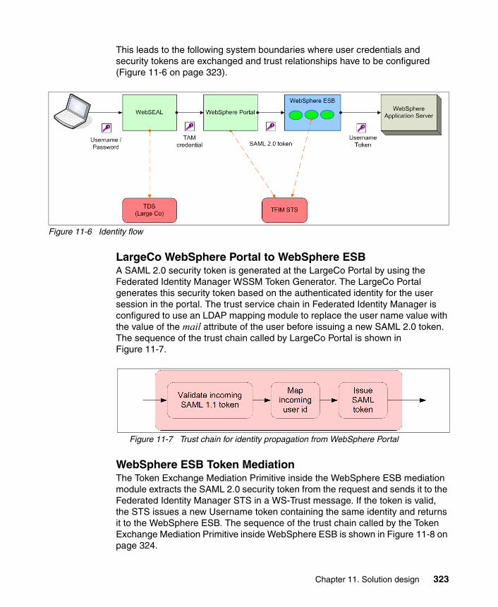
This leads to the following system boundaries where user credentials and security tokens are exchanged and trust relationships have to be configured (Figure 11-6 on page 323).
Figure 11-6 Identity flow
LargeCo WebSphere Portal to WebSphere ESBA SAML 2.0 security token is generated at the LargeCo Portal by using the Federated Identity Manager WSSM Token Generator. The LargeCo Portal generates this security token based on the authenticated identity for the user session in the portal. The trust service chain in Federated Identity Manager is configured to use an LDAP mapping module to replace the user name value with the value of the mail attribute of the user before issuing a new SAML 2.0 token. The sequence of the trust chain called by LargeCo Portal is shown in Figure 11-7.
Figure 11-7 Trust chain for identity propagation from WebSphere Portal
WebSphere ESB Token MediationThe Token Exchange Mediation Primitive inside the WebSphere ESB mediation module extracts the SAML 2.0 security token from the request and sends it to the Federated Identity Manager STS in a WS-Trust message. If the token is valid, the STS issues a new Username token containing the same identity and returns it to the WebSphere ESB. The sequence of the trust chain called by the Token Exchange Mediation Primitive inside WebSphere ESB is shown in Figure 11-8 on page 324.
Chapter 11. Solution design 323

Figure 11-8 Trust chain for identity mediation in WebSphere ESB
WebSphere ESB to SmallCo WebSphere Application ServerThe Username token issued by the STS is sent to the SmallCo WebSphere Application Server, which authenticates the request using the SmallCo directory. The Username token contains no password, so the authentication merely verifies that the user is in the SmallCo directory.
11.3.3 Authorization Services
The use of Authorization Services in this solution are described here.
Service consumer authorizationAccess Manager WebSEAL provides authorization of user requests based on URL (through access control lists (ACLs)). It can also restrict access based on time-of-week using a protected object policy. More complex authorization can be implemented using authorization rules.
WebSphere Portal has a role-based authorization model for restricting access to portlets and pages.
Authorizing access in the ESBThe LargeCo ESB is currently accessible to internal service consumers only. Service level authorization is not used in this example.
Authorizing access to the SmallCo applicationThe SmallCo application is a J2EE application running on WebSphere Application Server. Standard role-based J2EE Authorization Services are used. In this example, the application is a simple test application; all authenticated users are granted access to the application.
In more sophisticated J2EE applications, WebSphere Application Server can use a third-party authorization provider implementing the JACC provider. Tivoli Access Manager provides a JACC provider that can delegate the authorization decisions within the application to Access Manager. In this example, JACC provider is not configured.
324 Understanding SOA Security Design and Implementation

11.3.4 Confidentiality Services
In this section, the solution for transport and message level confidentiality is explained.
Transport level confidentiality is applied to the following communication channels:
� Communication between user browser and WebSEAL
To secure the communication channel between user browser and LargeCo WebSEAL server, HTTPS (using Secure Sockets Layer (SSL)) is implemented. WebSEAL terminates the HTTPS session of the user request.
� Communication between WebSEAL and LargeCo Portal Server
Often, clients want to use HTTPS (using SSL) to protect the communication between WebSEAL and LargeCo Portal Server. In this example, the data flow between the user browser and the SmallCo application does not use HTTPS.
� Communication to the Federated Identity Manager STS
The Federated Identity Manager WSSM token generator and the Token Exchange Mediation Primitive used in WebSphere ESB are exchanging WS-Trust messages with the Federated Identity Manager STS. Normally, SOAP over HTTPS is considered an appropriate mechanism to secure these channels, but in this example, WebSphere Portal, WebSphere ESB, and Federated Identity Manager STS are all within the LargeCo data center. SOAP over HTTP is implemented for simplicity.
� Communication to the Tivoli Directory Server
The Tivoli Directory Server is the enterprise user registry containing user identities including confidential information, such as passwords. Because WebSEAL is located inside the DMZ, the communication channel between the WebSEAL and LargeCo Tivoli Directory Server has to be configured to use secure LDAP (LDAPS) to protect the information. Regular LDAP transport is implemented for communication between Tivoli Directory Server and LargeCo Portal. Communication between SmallCo WebSphere Application Server and SmallCo Tivoli Directory Server also uses an unencrypted LDAP connection.
� Communication between the Access Manager components
Access Manager uses SSL for communication between its components by default. There is no additional configuration needed.
Chapter 11. Solution design 325

� Communication between Identity Manager and the adapters for Access Manager and LDAP
Identity Manager uses specific adapters for the target system to provision user identities. The communication between the adapters and the Identity Manager runtime is secured using SSL.
11.3.5 Integrity Services
Integrity Services protect data from unauthorized modification. Examples of data at rest that are protected in this design are:
� Cryptographic keys stored in the keystores for WebSEAL
� Security policy database and configuration files for Access Manager components
� Security audit records from all components
Tivoli Access Manager for Operating Systems is used to protect the file systems that contain this important data. Access Manager for Operating Systems supports fine-grained access control, which is not available on native operating system security. For example, Access Manager for Operating Systems can prevent unauthorized modification to file system objects by anyone other than authorized users executing authorized processes.
Message integrity protects the messages in transit from:
� Modification without detection (message integrity)� Being sent from a masquerading party (message origin authentication)� Exposure of the message content (message confidentiality)
In this example, the Web service messages travel from the LargeCo Portal to the SmallCo application via WebSphere ESB. All components are within the LargeCo internal network. In this example, no message level security is actually implemented (SR9 and SR10).
11.3.6 Audit Services
To meet the regulatory requirements and understand the operations of the security environment, auditing must be able to identify the individual user who was performing a transaction at every point in the transaction. Solution components in this example need to be enabled for auditing, and an audit infrastructure has to be in place. The auditing infrastructure provides mechanisms to submit, collect, persistently store, and report on audit data submitted as events.
326 Understanding SOA Security Design and Implementation

Tivoli Compliance Insight Manager (TCIM) is used to centralize and aggregate audit records from different components in the solution (Figure 11-9).
Figure 11-9 Adding auditing services
The following components are identified to be enabled for auditing:
� LargeCo:
– Access Manager (including WebSEAL)– Federated Identity Manager STS– Identity Manager– WebSphere ESB– WebSphere Portal
� SmallCo:
WebSphere Application Server
Chapter 11. Solution design 327

One of the benefits of using Compliance Insight Manager in this solution is that it is able to collect and process audit data from a variety of sources and normalize the data so that meaningful analysis and reporting can be performed centrally.
11.4 Security Enablers
Security Enablers are underlying technologies that are invoked by IT Security Services. In this solution, the following Security Enablers are used:
� Cryptographic services are used for the transport level encryption (SSL) between the user browser and the LargeCo WebSEAL server.
� Tivoli Directory Server is an LDAP V3 compliant directory. There are two logical Tivoli Directory Server instances in this solution: one instance used as the user registry for LargeCo and the other instance used as the user registry for SmallCo applications.
� Key Management Services are used to generate the X.509 key and certificate used in conjunction with the cryptographic services. The key and certificate are deployed at WebSEAL to provide SSL communication between the user browser and WebSEAL.
� Firewalls are used between the network zones in the solution to limit the traffic that is able to flow between zones to specific combinations of IP addresses, ports, and protocols.
� ISS Proventia Network IPS is used to provide intrusion prevention management for the network. This technology provides the ability to protect transactions at the application layer or the network. This enables the security administrator to reduce exposure to threats and misuse of network resources.
� ISS Proventia ADS is used to ensure there is no misuse of network resources and systems. By looking for anomalous behavior in the network, administrators are alerted immediately to problems that might arise.
� ISS Proventia Host-based products are deployed on the servers and desktops to protect systems from local intrusions and ensure system integrity.
� ISS Proventia Enterprise scanner is used to ensure that systems stay in compliance and have the latest patches and system configurations.
� Tivoli Security Operations Manager (TSOM) is used for security event management. By collecting runtime event data from multiple sources in the solution (for example, firewalls, ISS Proventia security products, operating systems, and application servers), Security Operations Manager is able to detect anomalies based on configured policies and generate alerts for system administrator intervention.
328 Understanding SOA Security Design and Implementation

� Network Time Protocol (NTP) provides time synchronization across the environment. This is required so that the lifetime of security tokens can be enforced without resorting to larger security token lifetimes.
11.5 Security Policy Management
In this section, the different aspects of Security Policy Management are designed.
11.5.1 Policy Administration
Policy Administration covers creation, modification, import, and export of security policies using the available security management tools. Security policies are described here that were derived from the LargeCo scenario business and security requirements listed in 10.1, “Business context” on page 308 and 10.2, “IT context” on page 309.
� Message protection policies:
– The HTTPS protocol is used for communication from external users to the LargeCo WebSEAL server.
– A SAML 2.0 security token is required to invoke the WebSphere ESB mediation from WebSphere Portal. The subject name in the SAML assertion should be the user’s Internet e-mail address. The SAML security token will be digitally signed.
– Where SOA communications do not cross a data center boundary, message confidentiality and integrity are not required (SR9).
– When SOA communications cross a data center boundary, message integrity is required (SR10).
– When SOA communications cross an external enterprise boundary, message confidentiality and integrity are both required (SR11).
– The signature method algorithm is RSA-SHA1.
� Provider policies:
– The user accessing the service has to be authenticated.
– The users accessing the service have to be authorized to use the service.
– Identity mediation must be done before the service request reaches the service providers.
Chapter 11. Solution design 329

Each component of the solution has to be enabled for auditing and the audit trails have to be able to identify the individual user who was performing a transaction at every point in that transaction.
11.5.2 Policy Distribution and Transformation
Authorization policies defined centrally in Access Manager for e-business are distributed to the Access Manager runtime environments where enforcement occurs. In this solution, the authorization policy is distributed to:
� WebSEAL
WebSEAL requires security policies for URL level access control.
� Federated Identity Manager Runtime
Service level authorization is performed as part of Federated Identity Manager trust chain processing.
11.5.3 Policy Decision and Enforcement
The policy enforcement points (PEPs) rely on decisions made by the policy decision points (PDPs). The PDPs contain the security policies defined in the infrastructure. This section outlines the PDPs and PEPs described in the LargeCo solution architecture. Solution components are described in the list, detailing their roles with respect to policy decision and enforcement:
� WebSEAL
The WebSEAL is the PEP for incoming Web traffic.
� Federated Identity Manager
Token validation and token exchange are performed by Federated Identity Manager. In this example, the incoming token type is a SAML assertion. During the validation process of SAML security tokens, Federated Identity Manager is the PDP and PEP for authenticating the Web service request by validating the SAML security tokens.
� WebSphere Application Server
WebSphere Application Server is the policy enforcement and policy decision point to enforce message level security.
� WebSphere Portal
WebSphere Portal is the PDP and PEP to enforce portal resources.
� Access Manager for e-business
Access Manager for e-business is the PDP for authorizing access to requested WebSphere Portal resources.
330 Understanding SOA Security Design and Implementation

� Identity Manager
Identity Manager is the PDP and PEP for provisioning policies.
11.5.4 Monitoring and Reporting
The policy replication subsystem in Tivoli Access Manager ensures that subscribers to its policy information are notified when changes to the policy have occurred, so that they can retrieve the latest version of the policy from the Tivoli Access Manager Policy Server.
Reporting is available from Tivoli Identity Manager to show users and the systems and resources for which they have access.
11.6 Governance and Risk Management
Early in the SOA initiative at LargeCo, an SOA Governance Board was formed. From the security perspective, the SOA Governance Board is responsible for defining security standards for interaction with services, establishing roles and responsibilities for policy administration, and how the services of SmallCo are integrated into LargeCo.
The risk management exercise performed by delegates of the SOA Governance Board resulted in the security requirements specified in Chapter 10, “Business scenario” on page 307.
11.7 Summary
This concludes the security solution design for accessing the SmallCo Web services application from the LargeCo Portal through an ESB. The complete solution design is shown in Figure 11-10 on page 332.
Chapter 11. Solution design 331

Figure 11-10 Complete solution design
In Chapter 12, “Technical implementation” on page 333 we go into more details covering the step-by-step process of implementing this solution.
332 Understanding SOA Security Design and Implementation

Chapter 12. Technical implementation
This chapter contains configuration instructions for implementing the solution architecture described in the preceding chapter. Installation steps and basic product configuration are not described. In some of the sections, existing knowledge and skills are assumed in order to focus on the aspects of constructing the solution that are more specific to service-oriented architecture (SOA) Security. In this chapter, we assume that you have some working knowledge of the products being used.
In this chapter, we cover the following aspects of the technical implementation:
� Implementation scope� Adding the token exchange mediation primitive using WebSphere Integration
Developer� Configuring identity propagation by modifying the LargeCo and SmallCo
applications� Deploying the LargeCo and SmallCo applications� Configure Federated Identity Manager trust chains� Testing the solution
12
© Copyright IBM Corp. 2007. All rights reserved. 333

12.1 Implementation scope
In terms of the SOA life cycle, this chapter describes:
� Assemble:
– Add token exchange mediation primitive to LargeCo mediation module– Add identity token generation to LargeCo portlet– Add identity token consumption to SmallCo WhoAmI application
� Deploy:
– Deploy LargeCo portlet– Deploy SmallCo WhoAmI application– Deploy LargeCo mediation– Configure LargeCo trust infrastructure
� Manage:
– Examine Tivoli Federated Identity Manager runtime trace– Examine WebSphere Enterprise Service Bus message log
12.2 Adding the token exchange mediation primitive using WebSphere Integration Developer
In order to transform security tokens from one format to another inside a mediation module, a token exchange mediation primitive is used. The token primitive extracts a security token from the incoming request and uses the Federated Identity Manager Security Token Service (STS) to transform this token to another. The new security token is included in the outgoing request from the enterprise service bus (ESB) to other services.
The components of the token exchange mediation primitive are:
� A WebSphere Integration Developer plug-in that provides a visual representation of the primitive within WebSphere Integration Developer
Note: Not all aspects of the design are implemented in this chapter. The following design items are not implemented in this chapter:
� In this environment, a test instance of WebSphere ESB running within the WebSphere Integration Developer tool is being used.
� User provision by Identity Manager.
� Auditing reports by Compliance Insight Manager.
� Intrusion detection and system protection by ISS Proventia Solutions.
334 Understanding SOA Security Design and Implementation

� The runtime component, which implements the logic required to perform a security token exchange in WebSphere ESB
The WebSphere Integration Developer/WebSphere ESB integration is available from the Tivoli Federated Identity Manager section of the IBM support Web site1. The integration package contains an integration guide, plug-in files, and runtime components. Use the instructions in the integration guide to configure the WebSphere Integration Developer and WebSphere ESB environments to use the token mediation primitive.
The WebSphere ESB mediation module supplied with this book has already added the token exchange mediation primitive. The sub-sections that follow describe how to perform these same steps with WebSphere Integration Developer.
12.2.1 Adding the token exchange mediation primitive
WebSphere Integration Developer workbench is used to create and modify WebSphere ESB mediations. To add the token exchange mediation primitive:
1. Using the examples supplied with this book, open the business integration project SmallWSToo_MedModule from the Business Integration pane on the left side. Expand the SmallWSToo_MedModule entry and double-click the Assembly Diagram entry. A predefined mediation module shows up in a new assembly diagram window as shown in Figure 12-1 on page 336.
1 Go to the IBM support Web site at the following URL: http://www.ibm.com/software/sysmgmt/products/support/IBMTivoliFederatedIdentityManager.htmlSearch for the following document: Tivoli Federated Identity Manager integration with WebSphere Developer Workbench. You will need to provide credentials to access this document, for example, IBM Passport Advantage® customers receive an IBM customer number that identifies their support contract (entitlement), and IBM employees use their intranet ID and password to gain entitlement.
Chapter 12. Technical implementation 335

Figure 12-1 SmallWSToo_MedModule Assembly Diagram
Figure 12-1 shows a simple service component architecture assembly diagram. It contains:
� An export component SmallWSLTPA that exposes a service to consumers of this mediation flow.
� A mediation flow component SmallWSToo_MedFlow.
� An import component import1 that invokes the SmallWSToo service.
The mediation flow component provides a visual composition model that allows easy orchestration of mediation functions. In this example, SmallWSToo_MedFlow needs to be modified to add a token exchange mediation primitive.
2. Select the SmallWSToo_MedFlow component and right-click. Select Open from the pop-up menu to open a new mediation flow editor window (See Figure 12-2 on page 337).
336 Understanding SOA Security Design and Implementation

Figure 12-2 Mediation flow editor
Figure 12-2 shows a simple connection between the method WhoAmI of SmallWSToo and the SmallWSTooPartner. There can be multiple mediation flows between the source operations and target operations.
3. A mediation flow must be selected before it can be modified in the mediation flow pane. Click the arrow line between the whoAmI method of SmallWSToo and SmallWSTooPartner inside the Operation connections pane. This shows the mediation flow in the Mediation flow pane.
A mediation flow has two directions: request and response. Only the request flow needs to be changed in this example. Click the Request:whoAmI tab below the mediation flow window. A simple mediation flow consists of only a message logger primitive between the Input and Callout (Figure 12-3 on page 338).
Chapter 12. Technical implementation 337

Figure 12-3 Simple mediation flow with MessageLogger only
The mediation flow shown in Figure 12-3 does nothing but log messages before calling the referenced service. In order to add a token exchange function, the token exchange mediation primitive needs to be added into the flow. Additional message logger primitives need to be added to log the message before and after it passes the token exchange mediation primitive to illustrate how the identity is being transformed. A separate message logger and error stop are added for improved error handling.
4. If the token exchange mediation primitive plug-in is deployed successfully, an icon for the token exchange mediation primitive (see the palette icon at the mouse cursor in Figure 12-4 on page 339) should show up on the left side of the mediation flow pane. Click that icon, and then click on a blank area inside the mediation flow pane to add a new token exchange mediation primitive to the flow diagram.
338 Understanding SOA Security Design and Implementation

Figure 12-4 Mediation flow highlighting the token mediation exchange primitive
5. After the token exchange mediation primitive has been added, click the message logger primitive in the palette and add two more message loggers into the mediation flow.
6. The next step is to delete the existing links between the MessageLogger1 and WhoAmI:SmallWSTooPartner callout. The mediation flow should resemble Figure 12-5 on page 340.
Chapter 12. Technical implementation 339

Figure 12-5 Mediation flow with all new primitives added
For each Message Logger primitive, there are two output terminals:
� out� fail
For the token exchange mediation primitive, there are four output terminals:
� output� invalid message failure� trust client failure� fail
7. Connect both out terminals of MessageLogger1 to the in terminal of the TokenExchangeMediation1.
8. Connect the output terminal of the TokenExchangeMediation1 to the in terminal of MessageLogger2.
9. Connect all other three failure condition output terminals of the TokenExchangeMediation1 to the in terminal of MessageLogger3.
10.Connect both output terminals of MessageLogger2 to the input of callout WhoAmI:SmallWSTooPartner.
The mediation flow should now resemble Figure 12-6 on page 341.
340 Understanding SOA Security Design and Implementation

Figure 12-6 Mediation Flow with the TokenExchangeMediation primitive
11.In order to handle the error situations from the TokenExchangeMediation1, a stop needs to be added after MessageLogger3. Both out and fail terminals from MessageLogger3 need to be linked to the stop as shown in Figure 12-7 on page 342.
Chapter 12. Technical implementation 341
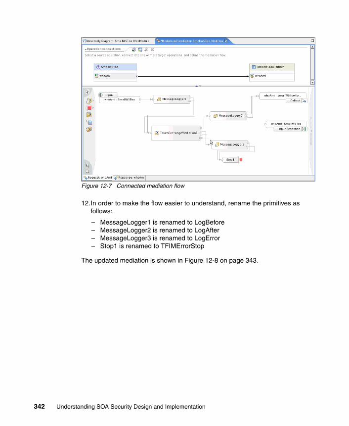
Figure 12-7 Connected mediation flow
12.In order to make the flow easier to understand, rename the primitives as follows:
– MessageLogger1 is renamed to LogBefore– MessageLogger2 is renamed to LogAfter– MessageLogger3 is renamed to LogError– Stop1 is renamed to TFIMErrorStop
The updated mediation is shown in Figure 12-8 on page 343.
342 Understanding SOA Security Design and Implementation

Figure 12-8 Mediation flow with renamed primitives
The properties of the new mediation primitives now need to be set.
13.For each message logger primitive, click the Details tab in the Properties. Set the value of the root property to / (forward slash character), as shown in Figure 12-9 on page 344. This causes the entire message (headers and body) to be written to the trace file. Be sure to set the root attribute for all three message loggers: LogBefore, LogAfter, and LogError.
Chapter 12. Technical implementation 343

Figure 12-9 Details in Message Logger Properties
14.Select the TokenExchangeMediation1 object and enter the following values for the attributes in the Details section. Table 12-1 shows the attribute names and values used in the example.
Table 12-1 Attributes and values for TokenExchangeMediation1
These attributes are needed by the token exchange mediation primitive to perform token exchange function:
� Trust Service URL points to the Federated Identity Manager STS endpoint.
Attribute Value
Trust Service URL http://www.large.com:9082/TrustServer/SecurityTokenService
Applies to Address http://www.small.com/SmallWSTooWeb/services/SmallWSLTPA
Issuer Address urn:large:wp:LargeWESBPortlet
Base Path /headers/SOAPHeader[“Security”]/value
Token Type SAML Assertion
344 Understanding SOA Security Design and Implementation
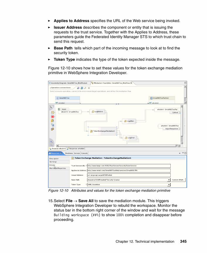
� Applies to Address specifies the URL of the Web service being invoked.
� Issuer Address describes the component or entity that is issuing the requests to the trust service. Together with the Applies to Address, these parameters guide the Federated Identity Manager STS to which trust chain to send this request.
� Base Path tells which part of the incoming message to look at to find the security token.
� Token Type indicates the type of the token expected inside the message.
Figure 12-10 shows how to set these values for the token exchange mediation primitive in WebSphere Integration Developer.
Figure 12-10 Attributes and values for the token exchange mediation primitive
15.Select File → Save All to save the mediation module. This triggers WebSphere Integration Developer to rebuild the workspace. Monitor the status bar in the bottom right corner of the window and wait for the message Building workspace (##%) to show 100% completion and disappear before proceeding.
Chapter 12. Technical implementation 345

If there are any problems that prevent WebSphere Integration Developer from rebuilding the workspace successfully, the error messages are displayed in the Problems tab. These errors must be rectified before proceeding.
12.2.2 Deploying the new mediation
In this example, a WebSphere ESB Server V6.0 has been set up on www.large.com, and it is already defined in the WebSphere Integration Developer workspace. The project SmallWSToo_MedModule has been added to the server, which makes modification and redeployment of the mediation module simple and straightforward:
1. Click the Servers tab in WebSphere Integration Developer and select server WebSphere ESB Server v6.0 @ www.large.com. Click the mouse right button and select Publish from the pull-down menu to update the mediation module in the WebSphere ESB server on www.large.com (Figure 12-11).
Figure 12-11 Publish the mediation module to WebSphere ESB
2. After the Publishing was successful message appears, click OK to close the pop-up window.
The mediation module is now deployed in the WebSphere ESB instance at LargeCo.
12.3 Configuring identity propagation by modifying the LargeCo and SmallCo applications
A portlet in the LargeCo Portal needs to be modified to generate the security token passed to the WebSphere ESB. The SmallCo Web service needs to be modified to consume the security token passed from the WebSphere ESB. These steps are performed using IBM Rational Application Developer 7.0 by editing the deployment descriptors for the LargeWESBPortlet and SmallWSTooWeb projects (Figure 12-12 on page 347).
346 Understanding SOA Security Design and Implementation

Figure 12-12 IBM Rational Application Developer project view
The applications supplied for download with this IBM Redbooks deliverable have already been configured for the identity propagation. The sub-sections that follow describe how to perform these same steps using Rational Application Developer.
12.3.1 Configuring request generator in LargeCo portlet
The request generator in the LargeWESBPortlet needs to be modified to call the Federated Identity Manager to generate a Security Assertion Markup Language (SAML) 2.0 security token to include with the outbound request:
1. Launch Rational Application Developer and navigate to the LargeWESBPortlet project. Double-click web.xml to open the deployment descriptor (Figure 12-13 on page 348).
Chapter 12. Technical implementation 347
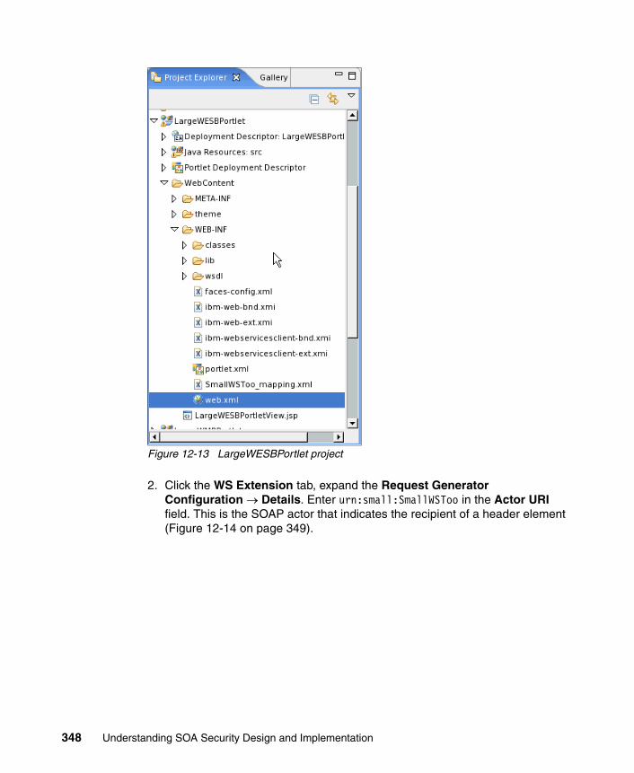
Figure 12-13 LargeWESBPortlet project
2. Click the WS Extension tab, expand the Request Generator Configuration → Details. Enter urn:small:SmallWSToo in the Actor URI field. This is the SOAP actor that indicates the recipient of a header element (Figure 12-14 on page 349).
348 Understanding SOA Security Design and Implementation

Figure 12-14 Details of request generator configuration
3. Expand the Security Token section and add an entry to specify that a SAML 2.0 security token is to be added to the outgoing messages (Figure 12-15). Click OK.
Figure 12-15 SAML 2.0 security token
Chapter 12. Technical implementation 349

4. Navigate to the WS Binding tab.
5. Expand the Security Request Generator Binding Configuration tab, and the Token Generator section within.
6. Add a new entry for how the SAML 2.0 security token will be generated (Figure 12-16 on page 351). Table 12-2 shows the correct values for the configuration parameters.
Table 12-2 Configuration parameters for the SAML 2.0 security token generator
7. The two properties required for the Callback Handler are shown in Table 12-3.
Table 12-3 Callback handler properties
Parameter Value
Token generator class name
com.tivoli.am.fim.wssm.tokengenerators.WSSMTokenGenerator
Security Token SAML20
Use Value Type <checked>
Local name urn:oasis:names:tc:SAML:2.0:assertion#Assertion
Callback handler com.tivoli.am.fim.callbackhandlers.WSSMTokenGeneratorCallbackHandler
Property Value
token.callback.handler.class.name com.tivoli.am.fim.wssm.callbackhandlers.SAMLACallbackHandler
xml.callback.handler.class.name com.tivoli.am.fim.wssm.callbackhandlers.JAASSubjectCallbackHandler
350 Understanding SOA Security Design and Implementation
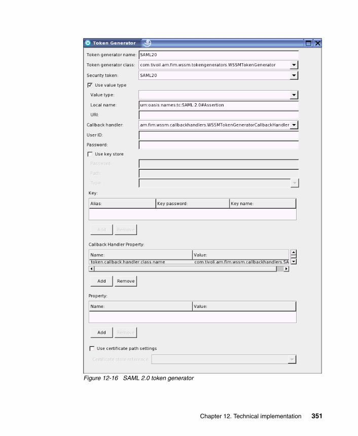
Figure 12-16 SAML 2.0 token generator
Chapter 12. Technical implementation 351
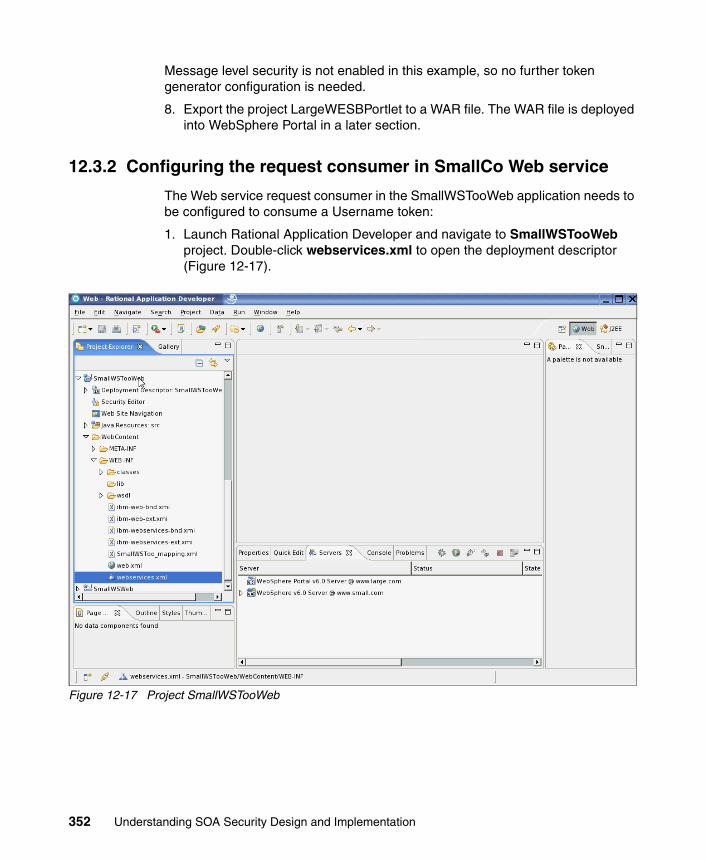
Message level security is not enabled in this example, so no further token generator configuration is needed.
8. Export the project LargeWESBPortlet to a WAR file. The WAR file is deployed into WebSphere Portal in a later section.
12.3.2 Configuring the request consumer in SmallCo Web service
The Web service request consumer in the SmallWSTooWeb application needs to be configured to consume a Username token:
1. Launch Rational Application Developer and navigate to SmallWSTooWeb project. Double-click webservices.xml to open the deployment descriptor (Figure 12-17).
Figure 12-17 Project SmallWSTooWeb
352 Understanding SOA Security Design and Implementation

2. Navigate to the Extensions tab, expand Request Consumer Service Configuration Details → Required Security Token. It is initially empty (Figure 12-18).
Figure 12-18 Add required security token
Chapter 12. Technical implementation 353

3. Click Add to add a new security token requirement. In the Required Security Token pop-up window (Figure 12-19):
– Enter UT as the name for this entry.
– Select Username Token from the Token type pull-down list.
Leave all other entries unchanged. Click OK to complete this action.
Figure 12-19 Required security token
354 Understanding SOA Security Design and Implementation

4. Expand the Server Service Configuration section and enter urn:small:SmallWSToo in the Actor URI field (Figure 12-20). This must match the value chosen when configuring the Web service client (Figure 12-14 on page 349).
Figure 12-20 Adding the actor URI in the service configuration
5. Expand the Caller part section within the same Request Consumer Service Configuration Details section and click Add.
Inside the Caller part pop-up window, enter UT in the Name field and select Username Token from the Token Type pull-down list.
Chapter 12. Technical implementation 355

6. Check the Use IDAssertion check box, and leave the Trust method name as None (Figure 12-21). This tells WebSphere Application Server to trust the data in the Username token and not validate it. Click OK.
Figure 12-21 Caller part
356 Understanding SOA Security Design and Implementation

7. In order to specify the actual classes that implement the token consumption, a binding configuration needs to be defined. Navigate to the Binding Configuration tab, expand Request Consumer Binding Configuration Details → Token consumer. There should be no token consumer defined initially (Figure 12-22).
Figure 12-22 Token consumer configuration
Chapter 12. Technical implementation 357

8. Click Add. Select or enter the following field values in Table 12-4 in the Token Consumer pop-up window. Do not change any other fields (Figure 12-23 on page 359). Click OK.
Table 12-4 Configuration data for token consumer
Name Value
Token consumer name UT
Token consumer class com.ibm.wsspi.wssecurity.token.IDAssertionUsernameTokenConsumer
Security token UT
Use value type <checked>
Value type Username Token
Use jaas config <checked>
jaas.config name system.wssecurity.IDAssertionUsernameToken
358 Understanding SOA Security Design and Implementation

Figure 12-23 Token consumer configuration
Chapter 12. Technical implementation 359

9. Save the SmallWSTooWeb project and export the application as an EAR file to complete the configuration changes.
12.4 Deploying the LargeCo and SmallCo applications
Now it is time to prepare the infrastructure and deploy the LargeWESBPortlet and the SmallWSTooWeb application.
12.4.1 Infrastructure configuration
In LargeCo, we assume that the following configuration for WebSphere Application Server, which hosts WebSphere Portal, has already been completed:
� Administrative and application security has been configured. In the ITSO lab environment, a Tivoli Directory Server instance is shared with Access Manager for e-business and Federated Identity Manager for this purpose.
� Prerequisite steps for using the Web Services Security Management component of Federated Identity Manager have been completed, following the instructions in the Web Services Security Management Guide in the Federated Identity Manager product documentation set:
– The ITFIM_WSSM variable was created.
– The ITFIM_WSSM shared library definition was created.
� The class loader for the WebSphere Application Server instance to be used by the LargeCo Portal has been configured to use the ITFIM_WSSM shared library definition.
� Sample user accounts have been created in both Access Manager for e-business and Tivoli Directory Server, including the mail attribute, which is required.
In SmallCo, the WebSphere Application Server, which hosts the SmallWSTooWeb application, does not have any integration with Access Manager for e-business, Federated Identity Manager, and Tivoli Directory Server configured. It is a stand-alone Web services application.
12.4.2 Deploy LargeWESBPortlet
To deploy LargeWESBPortlet:
1. Log on to LargeCo’s WebSphere Portal as a portal administrator and navigate to the Administration menu (Figure 12-24 on page 361).
360 Understanding SOA Security Design and Implementation

Figure 12-24 WebSphere Portal administration
2. Navigate to Portlet Management and click Web Modules, from the Manage Web Modules menu. Install or update the LargeWESBPortlet.war with the file saved at the end of 12.3.1, “Configuring request generator in LargeCo portlet” on page 347 (Figure 12-25 on page 362).
Chapter 12. Technical implementation 361

Figure 12-25 Install/update LargeWESBPortlet
12.4.3 Deploy SmallWSTooWeb application
Deploy the SmallWSTooWeb application to WebSphere Application Server.
In this example, there are no other security constraints defined for SmallCo. During deployment, accept all of the default values.
12.5 Configure Federated Identity Manager trust chains
In this section, two Federated Identity Manager trust chains need to be set up:
� Identity mediation in the LargeCo portlet
� Identity mediation in the Enterprise Service Bus
The Federated Identity Manager console is used to define both trust chains.
362 Understanding SOA Security Design and Implementation

12.5.1 Identity mediation for LargeCo portlet
In the LargeCo Portal, the Federated Identity Manager WSSM Token Generator is used to inject a signed SAML 2.0 assertion into outbound Web service requests to LargeCo WebSphere ESB. A Lightweight Directory Access Protocol (LDAP) mapping module is also used to map the SAML 1.1 user name to its corresponding e-mail address, and this e-mail address is used as the user name in the resultant SAML 2.0 assertion. The configuration of the corresponding trust chain in the Federated Identity Manager instance at LargeCo Portal is described in this section.
The steps to configure the LargeWESBPortletoutbound trust chain in the Federated Identity Manager instance at LargeCo Portal are:
1. Log on to the Integrated Solutions Console, which hosts the Federated Identity Manager Console.
2. Navigate to the Configure Trust Service → Trust Service Chains menu.
3. Create a new trust service chain with the following properties in Table 12-5.
Table 12-5 Properties for trust chain LargeWESBPortletoutbound
Note: The LDAP mapping module used in this example is not part of the current Federated Identity Manager 6.1.1 distribution; it has been supplied with this IBM Redbooks deliverable. For details about how to deploy the Default LDAP attribute mapping module into Federated Identity Manager, refer to 9.9.3, “Deploy LDAP mapping module” on page 278.
Property Value
Chain name LargeWESBPortletoutbound
AppliesTo Address REGEXP:(.*/SmallWSToo_MedModuleWeb/sca/SmallWSLTPA)
Issuer Address urn:itfim:wssm:tokengenerator
Request Type Validate
Chapter 12. Technical implementation 363

This trust chain is shown in Figure 12-26. The value for the AppliesTo Address is a regular expression representing the URL of the mediation on the WebSphere ESB. The Issuer Address indicates that this request to the trust service is generated by the Federated Identity Manager WSSM token generator.
Figure 12-26 Trust chain properties
364 Understanding SOA Security Design and Implementation
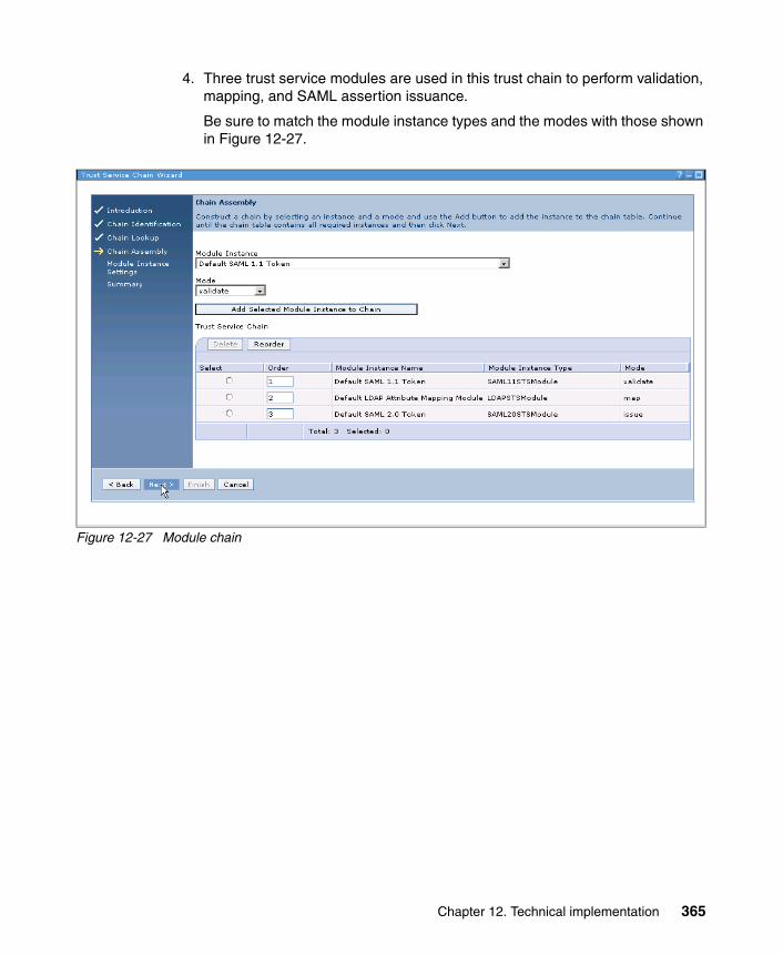
4. Three trust service modules are used in this trust chain to perform validation, mapping, and SAML assertion issuance.
Be sure to match the module instance types and the modes with those shown in Figure 12-27.
Figure 12-27 Module chain
Chapter 12. Technical implementation 365

5. When configuring the trust chain properties for the Default SAML 1.1 Token module, ensure that both the Enable one-time assertion use enforcement and the Enable Signature Validation check boxes are unchecked (Figure 12-28), because the Federated Identity Manager WSSM Token Generator does not sign the SAML 1.1 assertion that it sends to Federated Identity Manager.
Figure 12-28 SAML 1.1 validation configuration
6. When configuring the trust chain properties for the Default LDAP attribute mapping module, the following parameters in Table 12-6 on page 367 need to be supplied.
366 Understanding SOA Security Design and Implementation
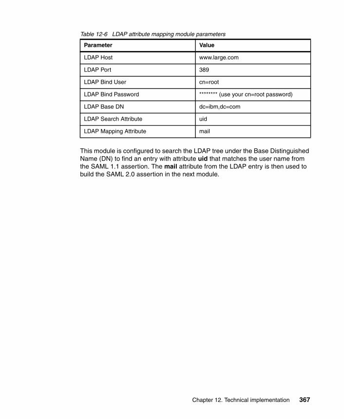
Table 12-6 LDAP attribute mapping module parameters
This module is configured to search the LDAP tree under the Base Distinguished Name (DN) to find an entry with attribute uid that matches the user name from the SAML 1.1 assertion. The mail attribute from the LDAP entry is then used to build the SAML 2.0 assertion in the next module.
Parameter Value
LDAP Host www.large.com
LDAP Port 389
LDAP Bind User cn=root
LDAP Bind Password ******** (use your cn=root password)
LDAP Base DN dc=ibm,dc=com
LDAP Search Attribute uid
LDAP Mapping Attribute mail
Chapter 12. Technical implementation 367
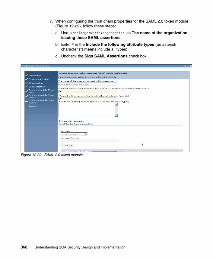
7. When configuring the trust chain properties for the SAML 2.0 token module (Figure 12-29), follow these steps:
a. Use urn:large:wp:tokengenerator as The name of the organization issuing these SAML assertions.
b. Enter * in the Include the following attribute types (an asterisk character (*) means include all types).
c. Uncheck the Sign SAML Assertions check box.
Figure 12-29 SAML 2.0 token module
368 Understanding SOA Security Design and Implementation

8. After verifying the summary of the trust module chain (Figure 12-30), save it.
Figure 12-30 Trust chain summary
Do not restart WebSphere Application Server at this time.
12.5.2 Identity mediation for LargeCo ESB
The token exchange mediation primitive inside the mediation module SmallWSMed_Module passes a SAML 2.0 assertion to the Federated Identity Manager STS and expects to receive a Username token. The configuration of the corresponding trust chain in the Federated Identity Manager instance at LargeCo Portal is described in this section.
Chapter 12. Technical implementation 369

The steps to configure the WebSphere ESB - LargeWESBPortlet to SmallWSToo trust chain are:
1. Log on to the Integrated Solutions Console, which hosts the Federated Identity Manager Console.
2. Navigate to the Configure Trust Service → Trust Service Chains menu.
3. Create a new trust service chain with the properties shown in Table 12-7.
Table 12-7 Properties for trust chain WebSphere ESB-LargeWESBPortlet to SmallWSToo
Note that the Issuer address urn:large:wp:largeWESBPortlet matches the issuer address defined in the Token Exchange Mediation Primitive attributes in Table 12-1 on page 344. This is how Federated Identity Manager finds the correct trust chain to process these WS-Trust requests. The trust chain configuration is shown in Figure 12-31 on page 371.
Property Value
Chain name WebSphere ESB - LargeWESBPortlet to SmallWSToo
Request Type Validate
AppliesTo Address http://www.small.com/SmallWSTooWeb/services/SmallWSLTPA
Issuer Address urn:large:wp:LargeWESBPortlet
370 Understanding SOA Security Design and Implementation

Figure 12-31 Trust chain LargeWESBPortlet to SmallWSToo
There are two modules in this trust chain for validation and issuance (Figure 12-32 on page 372). No mapping is required. The user name passed inside the SAML 2.0 assertion is the user e-mail address, which is assumed to be unique across LargeCo and SmallCo. This trust chain passes the e-mail address as user name in the Username Token to the SmallWSToo application.
Chapter 12. Technical implementation 371

Figure 12-32 Trust module chain
4. Note that a warning about not having an identity mapping module in the trust chain will be displayed. Acknowledge the warning at this time and continue.
372 Understanding SOA Security Design and Implementation

5. When configuring the Default SAML 2.0 Token module, uncheck the Enable Signature Validation check box (Figure 12-33).
Figure 12-33 Default SAML 2.0 Token module
Accept default values for all other fields.
Chapter 12. Technical implementation 373

Figure 12-34 shows a summary of the trust chain defined in this section.
Figure 12-34 Summary of Trust Chain
6. After saving the trust module chain, the WebSphere Application Server instance running the Federated Identity Manager Runtime must be restarted for these changes to take effect.
This concludes the necessary configuration and we can run our tests.
12.6 Testing the solution
After creating some test accounts, we will access the new service via the portal. After we have accessed the new service via the portal, we examine several request details and traces of the various involved systems.
374 Understanding SOA Security Design and Implementation

12.6.1 Creating test accounts
Some test accounts need to be created in LargeCo systems. Because LargeCo uses Access Manager WebSEAL to protect its portal, Access Manager user accounts can be created for testing purposes (Example 12-1).
Example 12-1 Creating a test user
pdadmin sec_master> user show nedLogin ID: nedLDAP DN: uid=ned,cn=users,dc=ibm,dc=comLDAP CN: Ned KellyLDAP SN: KellyDescription:Is SecUser: YesIs GSO user: NoAccount valid: YesPassword valid: Yes
The LDAP attribute mapping module is used to map a user ID to an e-mail address. The test accounts must have the mail attribute defined in the LDAP directory. This can be done by using LDAP tool ldapmodify (Example 12-2).
Example 12-2 Add LDAP attribute mail to user entry uid=ned
# idsldapmodify -D cn=root -w ?Enter password ==> ******dn: uid=ned,cn=users,dc=ibm,dc=comchangetype: modifyadd: mailmail: [email protected]
modifying entry uid=ned,cn=users,dc=ibm,dc=com
The resulting user entry in the LDAP directory is shown in Example 12-3.
Example 12-3 LDAP user entry for uid=ned
uid=ned,cn=users,dc=ibm,dc=comobjectclass=organizationalPersonobjectclass=personobjectclass=topobjectclass=inetOrgPersonuid=neduserpassword=passw0rdemployeeNumber=11-11-1880
Chapter 12. Technical implementation 375

[email protected]=KellygivenName=NedtelexNumber=ZNEDcn=Ned Kelly
Other LDAP administration tools, such as the Tivoli Directory Server Web Admin Tool, or any other LDAP editor can be used to modify LDAP user entries as well.
12.6.2 Accessing the service via the portal
Open a Web browser and access the LargeCo Portal server. The URL in the ITSO environment is:
https://www.large.com/wps/myportal
Authenticate as the user ned, created in the previous section. Navigate to Lab Home or the portal page where LargeWESBPortlet is deployed. Click the URL link representing the portlet. After a while, a message from the SmallCo application is displayed (Figure 12-35).
Figure 12-35 LargeWESBPortlet test result
The user’s e-mail address instead of the short user name appears in the result window. More detail about what is happening in the background can be learned
376 Understanding SOA Security Design and Implementation

by examining the Federated Identity Manager logs and WebSphere ESB message logs. This is described in the next two sections.
12.6.3 Federated Identity Manager Security Token Service interaction
Let us take a closer look at the the different Federated Identity Manager interaction messages.
Enable Federated Identity Manager traceLog on to the WebSphere Application Server administration console. Expand the Troubleshooting section and choose the server instance that hosts the Federated Identity Manager runtime (server1 in this example). Expand Logging and Tracing (Figure 12-36).
Figure 12-36 Federated Identity Manager trace
Select Diagnostic Trace and change the log detail levels for runtime traces to turn on all messages and traces for com.tivoli.am.fim sub-tree (Figure 12-37 on page 378).
Chapter 12. Technical implementation 377

Figure 12-37 Enable Federated Identity Manager trace
Now, rerun the test and look for the trace file under the log directory for server1 on the WebSphere Application Server. One sample trace file, trace.07.08.16.log, that was captured during the test is supplied with this IBM Redbooks deliverable (see Appendix D, “Additional material” on page 461).
Request from LargeCo WSSM Token GeneratorThe request from the LargeWESBPortlet to Federated Identity Manager carries an unsigned SAML 1.1 security token, generated by the WSSM Token Generator
378 Understanding SOA Security Design and Implementation

from the currently authenticated subject in WebSphere Application Server. In this trace, shown in Example 12-4, user ned was used to log in.
Example 12-4 WS-Trust request from WSSM Token Generator to STS
<wst:RequestSecurityTokenxmlns:wst="http://schemas.xmlsoap.org/ws/2005/02/trust"> <wst:RequestType
xmlns:wst="http://schemas.xmlsoap.org/ws/2005/02/trust">http://schemas.xmlsoap.org/ws/2005/02/trust/Validate
</wst:RequestType> <wst:Issuer
xmlns:wst="http://schemas.xmlsoap.org/ws/2005/02/trust"> <wsa:Address
xmlns:wsa="http://schemas.xmlsoap.org/ws/2004/08/addressing">urn:itfim:wssm:tokengenerator
</wsa:Address> </wst:Issuer> <wsp:AppliesTo
xmlns:wsp="http://schemas.xmlsoap.org/ws/2004/09/policy"> <wsa:EndpointReference
xmlns:wsa="http://schemas.xmlsoap.org/ws/2004/08/addressing"> <wsa:Address>
http://www.small.com:9084/SmallWSToo_MedModuleWeb/sca/SmallWSLTPA</wsa:Address> <wsa:PortType>SmallWSToo</wsa:PortType> <itfim:OperationName
xmlns:itfim="urn:ibm:names:ITFIM">whoAmI</itfim:OperationName>
</wsa:EndpointReference> </wsp:AppliesTo>
<wst:Base xmlns:wst="http://schemas.xmlsoap.org/ws/2005/02/trust"> <saml:Assertion
AssertionID="uuid6fa02792-0114-ed0d-70ba-c322fdc23676" IssueInstant="2007-08-16T17:02:20Z"Issuer="urn:itfim:wssm:callbackhandler:jaas" MajorVersion="1" MinorVersion="1" xmlns:saml="urn:oasis:names:tc:SAML:1.0:assertion"> <saml:Conditions NotBefore="2007-08-16T16:02:20Z"
NotOnOrAfter="2007-08-16T18:02:20Z" /> <saml:AuthenticationStatement AuthenticationInstant="2007-08-16T17:02:20Z"
AuthenticationMethod="urn:oasis:names:tc:SAML:1.0:am:unspecified"> <saml:Subject>
<saml:NameIdentifier>ned</saml:NameIdentifier> </saml:Subject>
</saml:AuthenticationStatement> <saml:AttributeStatement>
<saml:Subject>
Chapter 12. Technical implementation 379

<saml:NameIdentifier>ned</saml:NameIdentifier> </saml:Subject> <saml:Attribute
AttributeName="com.ibm.ws.security.auth.WSCredentialImpl"AttributeNamespace="urn:itfim:wssm:callbackhandler:jaas:credential:public">
<saml:AttributeValue>com.ibm.ws.security.auth.WSCredentialImpl@310d925d[com.ibm.ws.security.auth.distWSCredentialImpl@3102125d]
</saml:AttributeValue> </saml:Attribute> <saml:Attribute
AttributeName="com.ibm.ws.security.auth.WSCredentialImpl" AttributeNamespace="urn:itfim:wssm:callbackhandler:jaas:credential:private">
<saml:AttributeValue>com.ibm.ws.security.auth.WSCredentialImpl@310d925d[com.ibm.ws.security.auth.distWSCredentialImpl@3102125d]
</saml:AttributeValue> </saml:Attribute>
</saml:AttributeStatement> </saml:Assertion>
</wst:Base> </wst:RequestSecurityToken>
The LDAP mapping module writes a log message to describe the mapping it has performed (Example 12-5).
Example 12-5 Mapping information
[8/16/07 11:02:26:174 MDT] 0000003e ESMIdMapModul 3 com.tivoli.am.fim.trustserver.modules.mapping.ESMIdMapModule doMapping(STSRequest, STSResponse) Mapping ned to [email protected]
Response to LargeCo PortalThe response from Federated Identity Manager carries a signed SAML 2.0 security token with the e-mail address as user name, which is shown in Example 12-6.
Example 12-6 Response from STS to WSSM Token Generator
<wst:RequestSecurityTokenResponse wsu:Id="uuid6fa046da-0114-10b8-b1cc-e8f383b02e8a"xmlns:soapenv="http://schemas.xmlsoap.org/soap/envelope/" xmlns:soapenc="http://schemas.xmlsoap.org/soap/encoding/" xmlns:xsd="http://www.w3.org/2001/XMLSchema" xmlns:xsi="http://www.w3.org/2001/XMLSchema-instance" xmlns:wst="http://schemas.xmlsoap.org/ws/2005/02/trust" xmlns:wsu="http://docs.oasis-open.org/wss/2004/01/oasis-200401-wss-wssecurity-util
ity-1.0.xsd"> <wst:RequestedSecurityToken>
380 Understanding SOA Security Design and Implementation

<saml:Assertion ID="Assertion-uuid6fa0416a-0114-1827-b226-e8f383b02e8a" IssueInstant="2007-08-16T17:02:27Z" Version="2.0"xmlns:saml="urn:oasis:names:tc:SAML:2.0:assertion"> <saml:Issuer Format="urn:oasis:names:tc:SAML:2.0:nameid-format:entity">
urn:large:wp:tokengenerator</saml:Issuer> <saml:Subject>
<saml:NameID Format="http://docs.oasis-open.org/wss/2004/01/oasis-200401-wss-wssecurity-secext-1.0.xsd">
[email protected]</saml:NameID>
</saml:Subject> <saml:Conditions NotBefore="2007-08-16T17:01:27Z"
NotOnOrAfter="2007-08-16T17:03:27Z"> <saml:AudienceRestriction>
<saml:Audience>http://www.small.com:9084/SmallWSToo_MedModuleWeb/sca/SmallWSLTPA
</saml:Audience> </saml:AudienceRestriction>
</saml:Conditions> <saml:AuthnStatement AuthnInstant="2007-08-16T17:02:27Z">
<saml:AuthnContext> <saml:AuthnContextClassRef>
urn:oasis:names:tc:SAML:2.0:ac:classes:Password</saml:AuthnContextClassRef>
</saml:AuthnContext> </saml:AuthnStatement> <saml:AttributeStatement>
<saml:Attribute Name="com.ibm.ws.security.auth.WSCredentialImpl" NameFormat="urn:itfim:wssm:callbackhandler:jaas:credential:private"> <saml:AttributeValue xsi:type="xs:string"
xmlns:xs="http://www.w3.org/2001/XMLSchema" xmlns:xsi="http://www.w3.org/2001/XMLSchema-instance">
com.ibm.ws.security.auth.WSCredentialImpl@310d925d[com.ibm.ws.security.auth.distWSCredentialImpl@3102125d]
</saml:AttributeValue> </saml:Attribute> <saml:Attribute Name="MinorVersion"
NameFormat="urn:oasis:names:tc:SAML:1.0:assertion"> <saml:AttributeValue xsi:type="xs:string"
xmlns:xs="http://www.w3.org/2001/XMLSchema" xmlns:xsi="http://www.w3.org/2001/XMLSchema-instance">1
</saml:AttributeValue> </saml:Attribute> <saml:Attribute Name="MajorVersion"
NameFormat="urn:oasis:names:tc:SAML:1.0:assertion"> <saml:AttributeValue xsi:type="xs:string"
xmlns:xs="http://www.w3.org/2001/XMLSchema"
Chapter 12. Technical implementation 381

xmlns:xsi="http://www.w3.org/2001/XMLSchema-instance">1
</saml:AttributeValue> </saml:Attribute> <saml:Attribute Name="AssertionID"
NameFormat="urn:oasis:names:tc:SAML:1.0:assertion"> <saml:AttributeValue xsi:type="xs:string"
xmlns:xs="http://www.w3.org/2001/XMLSchema" xmlns:xsi="http://www.w3.org/2001/XMLSchema-instance">uuid6fa02792-0114-ed0d-70ba-c322fdc23676
</saml:AttributeValue> </saml:Attribute> <saml:Attribute Name="com.ibm.ws.security.auth.WSCredentialImpl"
NameFormat="urn:itfim:wssm:callbackhandler:jaas:credential:public"> <saml:AttributeValue xsi:type="xs:string"
xmlns:xs="http://www.w3.org/2001/XMLSchema" xmlns:xsi="http://www.w3.org/2001/XMLSchema-instance">
com.ibm.ws.security.auth.WSCredentialImpl@310d925d[com.ibm.ws.security.auth.distWSCredentialImpl@3102125d]
</saml:AttributeValue> </saml:Attribute> <saml:Attribute Name="AuthenticationInstant"
NameFormat="urn:oasis:names:tc:SAML:1.0:assertion"> <saml:AttributeValue xsi:type="xs:string"
xmlns:xs="http://www.w3.org/2001/XMLSchema" xmlns:xsi="http://www.w3.org/2001/XMLSchema-instance">2007-08-16T17:02:20Z
</saml:AttributeValue> </saml:Attribute> <saml:Attribute Name="Issuer"
NameFormat="urn:oasis:names:tc:SAML:1.0:assertion"> <saml:AttributeValue xsi:type="xs:string"
xmlns:xs="http://www.w3.org/2001/XMLSchema" xmlns:xsi="http://www.w3.org/2001/XMLSchema-instance">urn:itfim:wssm:callbackhandler:jaas
</saml:AttributeValue> </saml:Attribute> <saml:Attribute Name="IssueInstant"
NameFormat="urn:oasis:names:tc:SAML:1.0:assertion"> <saml:AttributeValue xsi:type="xs:string"
xmlns:xs="http://www.w3.org/2001/XMLSchema" xmlns:xsi="http://www.w3.org/2001/XMLSchema-instance">2007-08-16T17:02:20Z
</saml:AttributeValue> </saml:Attribute>
</saml:AttributeStatement> </saml:Assertion>
</wst:RequestedSecurityToken> <wst:RequestedAttachedReference
382 Understanding SOA Security Design and Implementation

xmlns:wss="http://docs.oasis-open.org/wss/2004/01/oasis-200401-wss-wssecurity-secext-1.0.xsd"> <wss:SecurityTokenReference>
<wss:KeyIdentifier ValueType="http://docs.oasis-open.org/wss/oasis-wss-saml-token-profile-1.0#SAMLAssertionID"
xmlns:saml="urn:oasis:names:tc:SAML:2.0:assertion"xmlns:wss="http://docs.oasis-open.org/wss/2004/01/oasis-200401-wss-wssecurity-secext-1.0.xsd">
Assertion-uuid6fa0416a-0114-1827-b226-e8f383b02e8a</wss:KeyIdentifier>
</wss:SecurityTokenReference> </wst:RequestedAttachedReference> <wst:Status>
<wst:Code>http://schemas.xmlsoap.org/ws/2005/02/trust/status/valid
</wst:Code> </wst:Status>
</wst:RequestSecurityTokenResponse>
Request from the Token Exchange Mediation PrimitiveThe request from the Token Exchange Mediation Primitive to the STS contains a SAML 2.0 assertion (Example 12-7).
Example 12-7 WS-Trust request to STS from token exchange mediation primitive
<wst:RequestSecurityToken xmlns:wst="http://schemas.xmlsoap.org/ws/2005/02/trust"> <wst:RequestType>
http://schemas.xmlsoap.org/ws/2005/02/trust/Validate</wst:RequestType> <wsp:AppliesTo xmlns:wsp="http://schemas.xmlsoap.org/ws/2004/09/policy">
<wsa:EndpointReferencexmlns:wsa="http://schemas.xmlsoap.org/ws/2004/08/addressing"> <wsa:Address>
http://www.small.com/SmallWSTooWeb/services/SmallWSLTPA</wsa:Address>
</wsa:EndpointReference> </wsp:AppliesTo> <wsa:Issuer xmlns:wsa="http://schemas.xmlsoap.org/ws/2005/02/trust">
<wsa:Address xmlns:wsa="http://schemas.xmlsoap.org/ws/2004/08/addressing">urn:large:wp:LargeWESBPortlet
</wsa:Address> </wsa:Issuer> <wst:Base>
<assertion:Assertion ID="Assertion-uuid6fa0416a-0114-1827-b226-e8f383b02e8a"IssueInstant="2007-08-16T17:02:27.0Z" Version="2.0" xmlns:assertion="urn:oasis:names:tc:SAML:2.0:assertion"> <assertion:Issuer Format="urn:oasis:names:tc:SAML:2.0:nameid-format:entity">
urn:large:wp:tokengenerator</assertion:Issuer> <assertion:Subject>
Chapter 12. Technical implementation 383

<assertion:NameID Format="http://docs.oasis-open.org/wss/2004/01/oasis-200401-wss-wssecurity-secext-1.0.xsd">
[email protected]</assertion:NameID>
</assertion:Subject> <assertion:Conditions NotBefore="2007-08-16T17:01:27.0Z"
NotOnOrAfter="2007-08-16T17:03:27.0Z"> <assertion:AudienceRestriction>
<assertion:Audience>http://www.small.com:9084/SmallWSToo_MedModuleWeb/sca/SmallWSLTPA
</assertion:Audience> </assertion:AudienceRestriction>
</assertion:Conditions> <assertion:AuthnStatement AuthnInstant="2007-08-16T17:02:27.0Z">
<assertion:AuthnContext> <assertion:AuthnContextClassRef>
urn:oasis:names:tc:SAML:2.0:ac:classes:Password</assertion:AuthnContextClassRef>
</assertion:AuthnContext> </assertion:AuthnStatement> <assertion:AttributeStatement>
<assertion:Attribute Name="com.ibm.ws.security.auth.WSCredentialImpl" NameFormat="urn:itfim:wssm:callbackhandler:jaas:credential:private">
<assertion:AttributeValue xsi:type="xsd:string" xmlns:xsi="http://www.w3.org/2001/XMLSchema-instance">
com.ibm.ws.security.auth.WSCredentialImpl@310d925d[com.ibm.ws.security.auth.distWSCredentialImpl@3102125d]
</assertion:AttributeValue> </assertion:Attribute> <assertion:Attribute Name="MinorVersion"
NameFormat="urn:oasis:names:tc:SAML:1.0:assertion"> <assertion:AttributeValue xsi:type="xsd:string"
xmlns:xsi="http://www.w3.org/2001/XMLSchema-instance">1
</assertion:AttributeValue> </assertion:Attribute> <assertion:Attribute Name="MajorVersion"
NameFormat="urn:oasis:names:tc:SAML:1.0:assertion"> <assertion:AttributeValue xsi:type="xsd:string"
xmlns:xsi="http://www.w3.org/2001/XMLSchema-instance">1
</assertion:AttributeValue> </assertion:Attribute> <assertion:Attribute Name="AssertionID"
NameFormat="urn:oasis:names:tc:SAML:1.0:assertion"> <assertion:AttributeValue xsi:type="xsd:string"
xmlns:xsi="http://www.w3.org/2001/XMLSchema-instance">uuid6fa02792-0114-ed0d-70ba-c322fdc23676
</assertion:AttributeValue>
384 Understanding SOA Security Design and Implementation

</assertion:Attribute> <assertion:Attribute Name="com.ibm.ws.security.auth.WSCredentialImpl"
NameFormat="urn:itfim:wssm:callbackhandler:jaas:credential:public"> <assertion:AttributeValue xsi:type="xsd:string"
xmlns:xsi="http://www.w3.org/2001/XMLSchema-instance">com.ibm.ws.security.auth.WSCredentialImpl@310d925d[com.ibm.ws.security.auth.distWSCredentialImpl@3102125d]
</assertion:AttributeValue> </assertion:Attribute> <assertion:Attribute Name="AuthenticationInstant"
NameFormat="urn:oasis:names:tc:SAML:1.0:assertion"> <assertion:AttributeValue xsi:type="xsd:string"
xmlns:xsi="http://www.w3.org/2001/XMLSchema-instance">2007-08-16T17:02:20Z
</assertion:AttributeValue> </assertion:Attribute> <assertion:Attribute Name="Issuer"
NameFormat="urn:oasis:names:tc:SAML:1.0:assertion"> <assertion:AttributeValue xsi:type="xsd:string"
xmlns:xsi="http://www.w3.org/2001/XMLSchema-instance">urn:itfim:wssm:callbackhandler:jaas
</assertion:AttributeValue> </assertion:Attribute> <assertion:Attribute Name="IssueInstant"
NameFormat="urn:oasis:names:tc:SAML:1.0:assertion"> <assertion:AttributeValue xsi:type="xsd:string"
xmlns:xsi="http://www.w3.org/2001/XMLSchema-instance">2007-08-16T17:02:20Z
</assertion:AttributeValue> </assertion:Attribute>
</assertion:AttributeStatement> </assertion:Assertion>
</wst:Base> </wst:RequestSecurityToken>
Response to the Token Exchange Mediation PrimitiveThe response to the Token Exchange Mediation Primitive from the STS contains a Username token with the user’s e-mail address as user name, which is shown in Example 12-8.
Example 12-8 WS-Trust response to token mediation primitive from STS
<wst:RequestSecurityTokenResponse wsu:Id="uuid6fa0ac76-0114-12f3-a9ef-e8f383b02e8a" xmlns:soapenv="http://schemas.xmlsoap.org/soap/envelope/" xmlns:soapenc="http://schemas.xmlsoap.org/soap/encoding/" xmlns:xsd="http://www.w3.org/2001/XMLSchema" xmlns:xsi="http://www.w3.org/2001/XMLSchema-instance" xmlns:wst="http://schemas.xmlsoap.org/ws/2005/02/trust"
Chapter 12. Technical implementation 385

xmlns:wsu="http://docs.oasis-open.org/wss/2004/01/oasis-200401-wss-wssecurity-utility-1.0.xsd">
<wst:RequestedSecurityToken> <wss:UsernameToken wsu:Id="username6fa0ac59-0114-1816-a358-e8f383b02e8a"
xmlns:wss="http://docs.oasis-open.org/wss/2004/01/oasis-200401-wss-wssecurity-secext-1.0.xsd"
xmlns:wsu="http://docs.oasis-open.org/wss/2004/01/oasis-200401-wss-wssecurity-utility-1.0.xsd">
<wss:Username>[email protected]</wss:Username> <wss:Nonce
EncodingType="http://docs.oasis-open.org/wss/2004/01/oasis-200401-wss-soap-message-security-1.0#Base64Binary">
FFFQ1RkUpMV9ECcmzm/oPQ==</wss:Nonce> <wsu:Created>2007-08-16T17:02:54Z</wsu:Created>
</wss:UsernameToken> </wst:RequestedSecurityToken> <wst:RequestedAttachedReference
xmlns:wss="http://docs.oasis-open.org/wss/2004/01/oasis-200401-wss-wssecurity-secext-1.0.xsd">
<wss:SecurityTokenReference> <wss:Reference URI="#username6fa0ac59-0114-1816-a358-e8f383b02e8a"
ValueType="http://docs.oasis-open.org/wss/2004/01/oasis-200401-wss-username-token-profile-1.0#UsernameToken" xmlns:wss="http://docs.oasis-open.org/wss/2004/01/oasis-200401-wss-wssecurity-secext-1.0.xsd" />
</wss:SecurityTokenReference> </wst:RequestedAttachedReference> <wst:Status>
<wst:Code>http://schemas.xmlsoap.org/ws/2005/02/trust/status/valid</wst:Code> </wst:Status>
</wst:RequestSecurityTokenResponse>
In this example, the SAML assertions are not signed, so there is no signature information inside the security tokens.
12.6.4 Examine WebSphere ESB message logs
Other than the Federated Identity Manager trace log, the WebSphere ESB mediation message logger can also provide insight into the messages before and after being processed by the Token Exchange Mediation Primitive. Remember that three message logger primitives were defined inside the mediation module in the example:
� LogBefore� LogAfter� LogError
386 Understanding SOA Security Design and Implementation

WebSphere ESB logs are written into the Cloudspace database that is shipped with WebSphere Application Server. To view the logs, first stop the WebSphere ESB server to avoid corrupting the Cloudspace database. Use the cview utility to view the logs inside the database. The database is located at: ${WESB_Install_Dir}/databases/EsbLogMedDB.
Open cview, which is located at: ${WESB_Install_Dir}/cloudscape/bin/embedded/cview.sh and check the data of the table MSGLOG (Figure 12-38).
Figure 12-38 Message logger data view
Select a message and click the Text Editor icon to view the message content with a text editor. Figure 12-39 on page 388 is an example of a LogBefore message shown in an editor window.
Chapter 12. Technical implementation 387

Figure 12-39 LogBefore message log
Example 12-9 on page 389 shows LogBefore message log content and Example 12-10 on page 391 shows LogAfter message log content.
388 Understanding SOA Security Design and Implementation

Example 12-9 LogBefore message log
<?xml version=”1.0” encoding=”UTF-8”?><ServiceMessageObject:smo xmlns:xsi=”http://www.w3.org/2001/XMLSchema-instance” xmlns:ServiceMessageObject=”http://www.ibm.com/websphere/sibx/smo/v6.0.1” xmlns:_0=”http://docs.oasis-open.org/wss/2004/01/oasis-200401-wss-wssecurity-secext-1.0.xsd” xmlns:assertion=”urn:oasis:names:tc:SAML:2.0:assertion” xmlns:envelope=”http://schemas.xmlsoap.org/soap/envelope/” xmlns:too=”https://apps.small.com/SmallWSToo/” xmlns:xsd=”http://www.w3.org/2001/XMLSchema”> <context/> <headers> <SMOHeader> <MessageUUID>6FA086D3-0114-4000-E000-1D7AC0A800C8</MessageUUID> <Version> <Version>6</Version> <Release>0</Release> <Modification>2</Modification> </Version> <MessageType>Request</MessageType> </SMOHeader> <SOAPHeader> <nameSpace>http://docs.oasis-open.org/wss/2004/01/oasis-200401-wss-wssecurity-secext-1.0.xsd</nameSpace> <name>Security</name> <value xsi:type=”_0:SecurityHeaderType” envelope:actor=”urn:small:SmallWSToo” envelope:mustUnderstand=”true”> <assertion:Assertion ID=”Assertion-uuid6fa0416a-0114-1827-b226-e8f383b02e8a” IssueInstant=”2007-08-16T17:02:27.0Z” Version=”2.0”> <assertion:Issuer Format=”urn:oasis:names:tc:SAML:2.0:nameid-format:entity”>urn:large:wp:tokengenerator</assertion:Issuer> <assertion:Subject> <assertion:NameID Format=”http://docs.oasis-open.org/wss/2004/01/oasis-200401-wss-wssecurity-secext-1.0.xsd”>[email protected]</assertion:NameID> </assertion:Subject> <assertion:Conditions NotBefore=”2007-08-16T17:01:27.0Z” NotOnOrAfter=”2007-08-16T17:03:27.0Z”> <assertion:AudienceRestriction> <assertion:Audience>http://www.small.com:9084/SmallWSToo_MedModuleWeb/sca/SmallWSLTPA</assertion:Audience> </assertion:AudienceRestriction> </assertion:Conditions> <assertion:AuthnStatement AuthnInstant=”2007-08-16T17:02:27.0Z”> <assertion:AuthnContext>
Chapter 12. Technical implementation 389

<assertion:AuthnContextClassRef>urn:oasis:names:tc:SAML:2.0:ac:classes:Password</assertion:AuthnContextClassRef> </assertion:AuthnContext> </assertion:AuthnStatement> <assertion:AttributeStatement> <assertion:Attribute Name=”com.ibm.ws.security.auth.WSCredentialImpl” NameFormat=”urn:itfim:wssm:callbackhandler:jaas:credential:private”> <assertion:AttributeValue xsi:type=”xsd:string”>com.ibm.ws.security.auth.WSCredentialImpl@310d925d[com.ibm.ws.security.auth.distWSCredentialImpl@3102125d]</assertion:AttributeValue> </assertion:Attribute> <assertion:Attribute Name=”MinorVersion” NameFormat=”urn:oasis:names:tc:SAML:1.0:assertion”> <assertion:AttributeValue xsi:type=”xsd:string”>1</assertion:AttributeValue> </assertion:Attribute> <assertion:Attribute Name=”MajorVersion” NameFormat=”urn:oasis:names:tc:SAML:1.0:assertion”> <assertion:AttributeValue xsi:type=”xsd:string”>1</assertion:AttributeValue> </assertion:Attribute> <assertion:Attribute Name=”AssertionID” NameFormat=”urn:oasis:names:tc:SAML:1.0:assertion”> <assertion:AttributeValue xsi:type=”xsd:string”>uuid6fa02792-0114-ed0d-70ba-c322fdc23676</assertion:AttributeValue> </assertion:Attribute> <assertion:Attribute Name=”com.ibm.ws.security.auth.WSCredentialImpl” NameFormat=”urn:itfim:wssm:callbackhandler:jaas:credential:public”> <assertion:AttributeValue xsi:type=”xsd:string”>com.ibm.ws.security.auth.WSCredentialImpl@310d925d[com.ibm.ws.security.auth.distWSCredentialImpl@3102125d]</assertion:AttributeValue> </assertion:Attribute> <assertion:Attribute Name=”AuthenticationInstant” NameFormat=”urn:oasis:names:tc:SAML:1.0:assertion”> <assertion:AttributeValue xsi:type=”xsd:string”>2007-08-16T17:02:20Z</assertion:AttributeValue> </assertion:Attribute> <assertion:Attribute Name=”Issuer” NameFormat=”urn:oasis:names:tc:SAML:1.0:assertion”> <assertion:AttributeValue xsi:type=”xsd:string”>urn:itfim:wssm:callbackhandler:jaas</assertion:AttributeValue> </assertion:Attribute> <assertion:Attribute Name=”IssueInstant” NameFormat=”urn:oasis:names:tc:SAML:1.0:assertion”> <assertion:AttributeValue xsi:type=”xsd:string”>2007-08-16T17:02:20Z</assertion:AttributeValue> </assertion:Attribute> </assertion:AttributeStatement> </assertion:Assertion> </value>
390 Understanding SOA Security Design and Implementation

</SOAPHeader> </headers> <body xsi:type=”too:whoAmIRequest”> <whoAmI/> </body></ServiceMessageObject:smo>
Example 12-10 LogAfter message log
<?xml version=”1.0” encoding=”UTF-8”?><ServiceMessageObject:smo xmlns:xsi=”http://www.w3.org/2001/XMLSchema-instance” xmlns:ServiceMessageObject=”http://www.ibm.com/websphere/sibx/smo/v6.0.1” xmlns:_0=”http://docs.oasis-open.org/wss/2004/01/oasis-200401-wss-wssecurity-secext-1.0.xsd” xmlns:_0_1=”http://docs.oasis-open.org/wss/2004/01/oasis-200401-wss-wssecurity-utility-1.0.xsd” xmlns:envelope=”http://schemas.xmlsoap.org/soap/envelope/” xmlns:too=”https://apps.small.com/SmallWSToo/”> <context/> <headers> <SMOHeader> <MessageUUID>6FA086D3-0114-4000-E000-1D7AC0A800C8</MessageUUID> <Version> <Version>6</Version> <Release>0</Release> <Modification>2</Modification> </Version> <MessageType>Request</MessageType> </SMOHeader> <SOAPHeader> <nameSpace>http://docs.oasis-open.org/wss/2004/01/oasis-200401-wss-wssecurity-secext-1.0.xsd</nameSpace> <name>Security</name> <value xsi:type=”_0:SecurityHeaderType” envelope:actor=”urn:small:SmallWSToo” envelope:mustUnderstand=”true”> <_0:UsernameToken _0_1:Id=”username6fa0ac59-0114-1816-a358-e8f383b02e8a”> <_0:Username>[email protected]</_0:Username> <_0:Nonce EncodingType=”http://docs.oasis-open.org/wss/2004/01/oasis-200401-wss-soap-message-security-1.0#Base64Binary”>FFFQ1RkUpMV9ECcmzm/oPQ==</_0:Nonce> <_0_1:Created>2007-08-16T17:02:54Z</_0_1:Created> </_0:UsernameToken> </value> </SOAPHeader> </headers> <body xsi:type=”too:whoAmIRequest”> <whoAmI/> </body></ServiceMessageObject:smo>
Chapter 12. Technical implementation 391

12.7 Summary
This concludes the implementation of accessing the SmallCo Web services application from the LargeCo Portal through an ESB.
392 Understanding SOA Security Design and Implementation

Appendix A. Introduction to service-oriented architecture
This appendix introduces service-oriented architecture (SOA) from a business and architecture perspective.
The appendix is organized into the following sections:
� “Service-oriented architecture overview” on page 394� “IBM SOA Reference Model: Challenges and drivers for SOA” on page 396� “Getting started with SOA” on page 405� “Web services and SOA” on page 408
A
© Copyright IBM Corp. 2007. All rights reserved. 393

Service-oriented architecture overviewThis section includes an overview for a service-oriented architecture (SOA).
Definition of a service-oriented architectureFigure A-1 highlights the key terms used to describe a service-oriented architecture.
Figure A-1 Definition of key terms for a service-oriented architecture
A service is representative of a repeatable business task. Services are used to encapsulate the functional units of an application by providing an interface that is well defined and implementation independent. Services can be invoked (consumed) by other services or client applications.
Service orientation defines a method of integrating business applications and processes as linked services.
Service-oriented architecture (SOA) can mean different things to different people depending on the person’s role and context (business, architecture, implementation, and operational). From a business perspective, SOA defines a set of business services composed to capture the business design that the enterprise wants to expose internally, as well as its customers and partners. From an architectural perspective, SOA is an architectural style that supports service orientation. At an implementation level, SOA is fulfilled using a standards-based infrastructure, programming model, and technologies, such as Web services. From an operational perspective, SOA includes a set of
... a service?
A repeatable businesstask. For example,
check customer credit or open a new account.
... Service-orientedarchitecture (SOA)?
An IT architecturalstyle that supportsservice orientation.
... service orientation?
A way of integrating yourbusiness as linked
services and theoutcomes that they bring.
... a compositionapplication?
A set of related and integrated services that
support a businessprocess built on an SOA.
394 Understanding SOA Security Design and Implementation

agreements between service consumers and providers that specify the quality of service, as well as report on the key business and IT metrics.
A composite application is a set of related and integrated services that support a business process built on an SOA.
Basic components of an SOAAt the most basic level, an SOA consists of the following three components:
� Service provider� Service consumer� Service registry
Each component can also act as one of the two other components. For example, if a service provider needs additional information that it can only acquire from another service, it acts as a service consumer. Figure A-2 shows the operations each component can perform.
Figure A-2 SOA components and operations
The service provider creates a service and in some cases publishes its interface and access information to a service registry.
Each provider must decide which services to expose, evaluate trade-offs between security and easy availability, and determine how to price the services
ServiceConsumer
ServiceProvider
ServiceRegistry
Publish1Discover2
Invoke3
- Flight Reservation- Car Hire- Hotel Booking- Mortgage Lending- Office Supplies
Application-A- Travel Agent- Retail Bank- Publishing House
Application-B- Airline/Car Rental/Hotel Chain- Mortgage Specialist/Investment Banks- Office Supplies Company
Request/Response
Appendix A. Introduction to service-oriented architecture 395

or determine how to exploit the value of the services if they are free. The provider also has to decide in which category the service should be listed and what sort of trading partner agreements are required to use the service.
The service registry is responsible for making the service interface and implementation access information available to service consumers.
The implementers of a service registry must consider the scope with which the registry will be implemented. For example, there are public service registries available over the Internet to an unrestricted audience, as well as private service registries that are only accessible to users within a company-wide intranet.
The service consumer locates (discovers) entries in the service registry and then binds to the service provider in order to invoke the defined service.
IBM SOA Reference Model: Challenges and drivers for SOA
In March 2006, IBM commissioned a Global CEO survey and found that 78% of CEOs surveyed believe that integrating business and technology is fundamental for innovation. Another key finding from this survey was that only one in ten CEOs believes his or her organization has the ability to be very responsive to changing market conditions.
As noted from the survey, businesses need the ability to integrate business and technology rapidly to achieve their business objectives. Businesses also have a strong desire to leverage the investment of existing business applications and systems without a complete and costly rewrite. There are many schemes that exist today to integrate systems within and between enterprises. In most cases these solutions are proprietary, not easily adaptable, and not responsive to rapid changes needed by the business.
There is a growing demand for an architecture and technologies that support the connection or sharing of resources and data in a very flexible and industry- standard manner. There is a need to further structure large applications into building blocks that can be reused and composed into business processes.
A shift toward a service-oriented approach standardizes the interaction with applications and business processes and allows for more flexibility in the process. By adopting an SOA approach, existing application functionality can be turned into reusable services that can be consumed by a new set of client applications and users. SOA brings the flexibility that is vital to realizing innovation and desired outcomes of business.
396 Understanding SOA Security Design and Implementation

Business requirements and drivers for SOAFigure A-3 highlights the common elements of a business that require flexible integration.
Figure A-3 Business requirements
Here, we summarize the common business drivers that require rapid and flexible integration of IT systems:
� Support an agile business model.
The marketplace can be very dynamic and competitive. There is a great need to have a business model and IT architecture that can rapidly change to support the business model and its objectives.
Tip: The alignment of IT with business goals can be summarized as collaborative business and IT decision-making that ensures that:
� IT investments are made based on business objectives.
� IT service delivery provides a business result.
� Business priorities are assessed with IT capabilities and limitations in mind.
Appendix A. Introduction to service-oriented architecture 397

� Reduce cycle time and costs.
Eliminate duplicate systems by reusing existing applications. This has the effect of reducing the time required to integrate systems. It also reduces cost and simplifies the skill set required to implement the solution.
When applying these concepts to external business processes, enterprises can move from costly manual transactions to automated transactions with suppliers.
� Simplify integration across the enterprise.
Many existing IT systems can be inhibitors to change. They are too complex and, as a result, inflexible. Also, existing integration includes multiple technologies and point-to-point integration, which is often inflexible. The need to simplify integration is essential, especially considering the challenges raised from events such as business mergers and acquisitions.
� Achieve better IT use and return on investment.
Return on investment (ROI) is a comparison of profit earned or lost for the investment with the amount invested. The investment in IT should facilitate the business objective and help the business achieve the targeted ROI.
Greater need for a flexible architectureThere are many possible reasons that a flexible business model is needed, such as business transformation, business process outsourcing, mergers, and acquisitions. SOA provides a flexible IT infrastructure and on demand operating environment to support the initiatives of a flexible business model.
For the purposes of comparison with SOA, we highlight the integration deficiencies of monolithic (silos) and component-based architectures. Next, we describe the flexibility gained by using an SOA approach.
Historically, business applications were built with a monolithic purpose (silos). While this kind of architecture can be effective, it is often very difficult to change and integrate with other applications within the enterprise and between enterprises (custom-coded connections are required).
For example, a monolithic business application must periodically synchronize inventory information, as you can see in Figure A-4 on page 399. In this approach, pricing information for each Web order is inserted differently based on the application structure. Lastly, there is no common customer or inventory database to be shared across the enterprise or flexibility in the business processes.
398 Understanding SOA Security Design and Implementation

Figure A-4 Monolithic business application (silos)
Although component-based application architecture does define services as units of business logic, there are some inherent problems with this approach. The flow of control is bound into the service logic. The transformation of data formats is also bound to the service logic. There is tight coupling between the services, as seen in Figure A-5, thus making this application integration architecture fragile, giving it a spaghetti-like appearance.
Figure A-5 Component-based application
Sales Orders& Supply
Chain
Pricing
WebOrders
Inventory
SalesOrders
Shipments
CustomersPricing
Web Orders
Appendix A. Introduction to service-oriented architecture 399

When using an SOA approach (see Figure A-6), the services are defined as units of business logic separated from the flow of control and routing, and the data transformation and protocol transformation. This approach provides loose coupling, thus making this approach much more flexible for integration.
Figure A-6 SOA-based application
Why SOA now In the previous section, we explained how a service-oriented architecture provides the flexibility to align your IT with your business goals. In this section, we explain why SOA is the right choice now. When there is a shift in architecture, it is important to understand why a shift is needed and evaluate the maturity level of the architecture that supports adoption.
We highlight the following key reasons why SOA is the right choice now:
� Business driving a shift in IT� Enables flexibility of both IT and business� Open standards and platforms� Best practices� Software for SOA
Business driving a shift in ITTable A-1 on page 401 provides a summary of business needs that are driving a shift in IT from function-oriented to process- and service-oriented to achieve flexibility.
Inventory
SalesOrders
Shipments
CustomersPricing
Web Orders
400 Understanding SOA Security Design and Implementation

Table A-1 Shift in IT driven by business
Enables flexibility of both IT and businessSOA enables flexibility of both IT and business through flexible connectivity of business services:
� Represents applications or data as a service with a standardized interface
� Enables applications as services to exchange structured information (messages, documents, and other business objects)
� Mediates the message exchange through an Enterprise Service Bus (ESB)
� Provides on-ramps to the bus for existing applications and systems
From function-oriented To process and service-oriented
Build for permanence Build to change
One long development cycle Incremental development cycle
Application silos Orchestrated solutions that work together
Tightly coupled Loosely coupled
Structure applications using components and objects
Structure applications using services
Known implementation Implementation abstraction
Appendix A. Introduction to service-oriented architecture 401

Open standards and platformsAnother key reason that SOA is the right choice for your enterprise is that it is based on open standards and platforms, as summarized in Figure A-7. These open standards are widely adopted across the industry.
Figure A-7 Summary of SOA open standards and platforms
IBM continues to be a leader in SOA-based technologies, products, and solutions. IBM is a key partner in helping define the specifications and technologies used to implement an SOA, such as Web Services, Service Component Architecture (SCA), and Service Data Objects (SDOs).
Best practicesBest practices are used to deliver a particular outcome by leveraging the knowledge learned from experience. Best practices include methodologies, techniques, guidelines, and patterns. By leveraging the knowledge captured in best practices listed here, your project can be run with fewer problems and be deployed more rapidly.
Here is a list of best practices in use today:
� SOA Adoption
The SOA adoption process provides guidelines that assist in developing a roadmap toward a successful migration to an SOA.
� SOA Governance
SOA Governance helps clients extend the planned SOA across the enterprise in a controlled manner.
IBM is the #1 commercial supporter
Open Operating System Choice Includes Linux
IBM contributed technology to J2EE & helped form the Apache Software Foundation
Open Application Server J2EE and Apache
IBM led or co-led the creation of SOAP, WSDL, UDDI, WS-Security, BPEL4WS …
Open Application Integration Web Services
IBM donated $40M of initial technology
Open Development Integration Platform Eclipse
402 Understanding SOA Security Design and Implementation

� Methodology
A well-established set of methodologies can help to break down complex problems into smaller and more manageable pieces that are easier to analyze and, therefore, make it easier to develop solutions to address the problems. Example methodologies include the Component Business Model™ (CBM), IBM Service Integration Maturity Model (SIMM), Rational Unified Process® (RUP®), and Service-Oriented Modeling and Architecture (SOMA).
� Process modeling
Process modeling is used to define business processes. A process flow is a sequence of tasks and decision elements with multiple branches, linked by connectors.
� Model-driven development
Model-driven development is a style of software development where the primary software artifacts are models from which code and other artifacts are generated. A model is a description of a system from a particular perspective, omitting irrelevant detail so that the characteristics of interest are clearer.
� Reference architecture
A reference architecture provides the underlying architecture components used to overcome the initial problems of finding an architecture with which to begin. The most notable reference architecture for SOA is the IBM SOA Foundation.
� Patterns
As a general principle, starting from the beginning each time should be avoided. The use of patterns is one specific form of capturing and reusing recurring design elements. For example, the Patterns for e-business include reusable architecture and implementation assets used to accelerate the creation of a solution design and implementation.
Software for SOAThe marketplace offers many software choices for SOA. IBM is the market leader in providing mature software and solutions for SOA.
SOA approach for building a solutionThis section includes an example SOA approach for building a solution. In this example, the company wants to implement a new business process to support customers who are placing orders from an Internet Web site.
Appendix A. Introduction to service-oriented architecture 403

The company has existing retail, warehouse, and billing systems, as seen in Figure A-8. The company wants to build new business processes by reusing the functionality provided by the existing systems rather than having to write new applications or new proprietary interfaces to the existing systems.
Figure A-8 Service-oriented approach to building systems
If the company has already adopted an SOA approach, it will have defined the interfaces to its existing systems in terms of the functions or services that they offer in support of building business processes. The defined interfaces make building the new system Web front end very simple. The company simply needs to develop an application that invokes (consumes) services to complete the new business process.
By using an SOA approach, companies are able to build horizontal business processes that integrate systems, people, and processes from across the enterprise quickly and easily in response to changing business needs.
BusinessProcess
BillCustomer
DefinedServices
ReceiveOrder
Service
CustomerBilling
Service
FulfillOrder
Service
RestockService
ITSystems
WebApplication
RetailSystem
CRMWarehouse
System
ReceiveOrder
FulfillOrder Restock
404 Understanding SOA Security Design and Implementation

Getting started with SOAIn this section, we explore the question of how to get started with SOA from both a business and an architectural perspective.
SOA adoptionSOA adoption provides an iterative and incremental process and guidelines that assist in developing a road map toward a successful migration to SOA. As seen in Figure A-9, the SOA adoption process begins by defining the scope of possible projects that fit the criteria for being a good fit for a service-oriented architecture.
Figure A-9 SOA adoption process
There are two primary perspectives, including strategic vision and project plan. The strategic vision perspective describes the business and IT statement of direction, which can be used as a guideline for decision making, organizational buy-in, and standards adoption. The project plan perspective (or tactical perspective) refers to implementation projects to meet immediate needs of the current business drivers.
Defining the strategic vision starts with assessing the business current maturity across multiple dimensions including business, methodology, and technical. The IBM Service Integration Maturity Model (SIMM) can be used to help in this assessment. If you are more comfortable with starting with a self-assessment, you can use the IBM online SOA Assessment Tool at:
http://www.ibm.com/software/solutions/soa/soaassessment/index.html
Appendix A. Introduction to service-oriented architecture 405

After the assessment has been performed, the business must establish targets for where they want to be. This includes documenting important goals and metrics for transition across the maturity dimensions. In addition, it is important to have regular checkpoints to reassess the vision.
IBM SOA entry pointsAs seen in Figure A-10, SOA connects people, processes, and information. To help clients get started with SOA, IBM has defined three core business-centric starting points (people, processes, and information) and two IT-centric starting points (connectivity and reuse). These are known as the SOA entry points.
Figure A-10 SOA connects people, processes, and information
Through business-centric SOA, companies can tie IT projects to their business needs directly by addressing their company’s immediate pain points:
� People: Productivity through collaboration
Improve people productivity by aggregating views that deliver information and interaction in the context of a business process. This enables human and process interaction with consistent levels of service.
Wired and wireless devicesGlobal 24x7 access and real-time collaboration needsUnconsolidated and untailored information
Distributed data environmentsHeterogeneous data types and sourcesUntransformed and inconsistent data
Development and integration of application assetsApplication silos (existing and packaged applications)Heterogeneous internal and external systems
406 Understanding SOA Security Design and Implementation

Start by building a view of a key business process by aggregating information to help people make better decisions. The next steps are tighter management of performance with alert-driven dashboards that link to more processes.
� Process: Business process management for continuous innovation
Deploy innovative business models quickly with reusable and optimized processes to adapt the enterprise to changing opportunities and threats.
Start by modeling an under-performing process, remove bottlenecks, and then simulate and deploy the optimized process. Next, create flexible linkages between multiple processes across the enterprise and outside the firewall to suppliers and partners. Then, monitor the process to measure and track performance.
� Information: Delivering information as a service
Improve business insight and reduce risk with trusted information services delivered in-line and in context.
Start by discovering and understanding information sources, relationships, and the business context. The next steps are to expand the volume and scope of the information delivered as a service across internal and external processes.
The IT-centric entry points to help the enterprise integrate the business-centric SOA entry points are as follows:
� Connectivity: Underlying connectivity to enable business-centric SOA
Connectivity has always been a key requirement. SOA brings new levels of flexibility. As well as acting as a building block for additional SOA initiatives, connectivity provided through SOA has distinct, stand-alone value.
� Reuse: Create flexible, service-based business applications
Cut costs, reduce cycle times, and expand access to core applications through reuse. Analysts estimate it is up to five times less expensive to reuse existing applications than to write new applications.
Use portfolio management to consider which assets you need to run your company. Identify high-value existing IT assets and service-enable them for reuse. Satisfy remaining business needs by creating new services. Finally, create a service registry and repository to provide centralized access and control of these reusable services.
Appendix A. Introduction to service-oriented architecture 407

IBM SOA FoundationThe IBM SOA Foundation is an integrated, open standards-based set of IBM software, best practices, and patterns to provide you with the architecture knowledge to get started with SOA. The key elements of the IBM SOA Foundation are the SOA life cycle (model, assemble, deploy, and manage), reference architecture, programming model, and SOA scenarios.
The SOA Foundation scenarios (or simply SOA scenarios) are representative of common scenarios of use of IBM products and solutions for SOA engagements. The SOA scenarios quickly communicate the business value, architecture, and IBM open standards-based software used within the SOA scenario. The concept of realizations is used to provide more specific solution patterns and IBM product mappings within the SOA scenarios.
The SOA scenarios can be used as a reference architecture implementation (starting point) to accelerate the SOA architecture and implementation of your scenario. The SOA scenarios can be implemented using an incremental SOA adoption approach, whereby a client can incrementally add elements of other SOA scenarios to the environment to achieve their business objectives.
Web services and SOAThis section describes the core technologies of Web services, as well as how Web services are used to implement an SOA.
Web services technologiesWeb services technology is a collection of standards (or emerging standards) that can be used to implement an SOA. Web services technology is vendor- and platform-neutral, interoperable, and supported by many vendors today.
Web services are self-contained, modular applications, that can be described, published, located, and invoked over networks. Web services encapsulate business functions, ranging from a simple request-reply to full business process interactions. The services can be new or wrapped around existing applications.
Note: For more detailed information about Web services, we recommend that you read WebSphere Version 6 Web Services Handbook Development and Deployment, SG24-6461.
408 Understanding SOA Security Design and Implementation

Core elementsThe following are the core technologies used for Web services:
� Extensible Markup Language (XML)
XML is the markup language that underlies most of the specifications used for Web services. XML is a generic language that can be used to describe the content in a structured way, separated from its presentation to a specific device.
� Simple Object Access Protocol (SOAP)
SOAP is a specification for the exchange of structured XML-based messages between the service provider, service consumer, and service registry, consisting of three parts:
– The format of a SOAP message is an envelope containing zero or more headers and exactly one body. The envelope is the top element of the XML document, providing a container for control information, the addressee of a message, and the message itself. Headers contain control information, such as quality-of-service attributes. The body contains the message identification and its parameters.
– Encoding rules are used for expressing instances of application-defined data types. SOAP defines a programming language independent data type schema based on an XML Schema Descriptor (XSD), plus encoding rules for all data types defined to this model.
– RPC representation is the convention for representing remote procedure calls (RPC) and responses.
SOAP, in principle, is a protocol-independent transport. Consequently, it can potentially be used in combination with a variety of protocols, such as HTTP, JMS, SMTP, or FTP. Currently, the most common way of exchanging SOAP messages is through HTTP, which is also the only protocol supported by WS-I Basic Profile 1.0.
� Web Services Description Language (WSDL)
WSDL is an XML-based interface and implementation description language. A WSDL document contains the following main elements:
– Types is the container for data type definitions using a type system, such as an XML Schema.
– An abstract, typed definition of the data being communicated, a message can have one or more typed parts.
– A port type is an abstract set of one or more operations supported by one or more ports.
Appendix A. Introduction to service-oriented architecture 409

– An operation is an abstract description of an action supported by the service that defines the input and output message and optional fault message.
– The binding is a concrete protocol and data format specification for a particular port type. The binding information contains the protocol name, the invocation style, a service ID, and the encoding for each operation.
– The service is a collection of related ports.
– The port is a single endpoint, an aggregation of a binding and a network address.
� Universal Description, Discovery, and Integration (UDDI)
UDDI is both a client-side API and a SOAP-based server implementation that can be used to store and retrieve information about service providers and Web services.
StandardsFigure A-11 on page 411 displays a stacked view of Web services technologies. Most of the technologies displayed have been standardized. Because interoperability is a key goal of Web services, an open industry organization known as the Web services Interoperability Organization (WS-I) has been created to allow interested parties, such as IBM and Microsoft, to work together to maximize interoperability between Web services implementations. For more information about WS-I, visit their Web site:
http://ws-i.org
Note: Web services standards are evolving at a rapid pace. For current information, we recommend that you reference the Web services standards information online at sites, such as IBM developerWorks:
http://www.ibm.com/developerworks/webservices/standards/
410 Understanding SOA Security Design and Implementation

Figure A-11 Stack view of Web services technology
Web services for J2EEWeb services for J2EE V1.1 (WSEE) support is included in the J2EE V1.4 specification, which is used by WebSphere Application Server V6. The Java API for XML-based RPC (JAX-RPC) provides the programming model for SOAP-based applications by abstracting the runtime details and providing mapping services between Java and WSDL.
Exposing Web servicesThe port component is a fundamental part of a Web service that used to define the programming model artifacts that make the Web service portable. The programming model includes:
� A WSDL definition provides the description of a Web service.
� The service endpoint interface (SEI) defines the operations of the Web service.
� A service implementation bean implements the SEI methods to provide the business logic of the Web service.
� The security role references provide instance-level security checks across different modules.
WS-Policy
WS-Security family of
specifications
UDDI
Other protocolsOther services
Business Process Execution Language (BPEL)
WSDL
SOAP, SOAP Attachments
XML, XML Infoset
Transports
WS-Coordination
WS-Transactions
WS-Reliable Messaging
WS-DistributedManagement
Descriptionand Discovery
Messagingand Encoding
Transport
Quality of Service
BusinessProcesses
Appendix A. Introduction to service-oriented architecture 411

From a server programming model perspective, there are primarily two types of J2EE application artifacts exposed as Web services (service provider):
� Stateless session EJB (EJB container)
� JAX-RPC servlet-based service that invokes a JavaBean, known as a service endpoint (Web container)
There are three principal approaches to generating a Web service, depending on the elements that are used to start the creation of the service:
� An existing application is used to generate the Web service, which includes a service wrapper used to expose application functionality. This is known as the bottom-up approach.
� An existing service definition WSDL is used to generate a new application for a specific programming language and model. This is known as the top-down approach.
� An existing group of already generated Web services provides a new combination of functionality (multiple services). Composing a new Web service in this way might include the use of workflow technologies.
Invoking Web servicesThe J2EE client container provides the WSEE runtime used by a Web services client application to access and invoke Web service methods. The J2EE client container is responsible for the JNDI name to service implementation mapping.
From a client application programming perspective, there are three mechanisms used to invoke a Web service (service consumer) from the Web service client application:
� A static stub is created before being deployed to the runtime environment. This requires complete knowledge of the WSDL.
� A dynamic proxy class is created during runtime. Only a partial WSDL definition is required (port type and bindings).
� A dynamic invocation interface does not require WSDL knowledge. The signature or service name is unknown until runtime.
The task to build or generate a Web service client (service consumer) depends on the methods of how the client is binding to a Web service server. The client uses a local service stub or proxy to access the remote server and service. The WSDL document is used to generate or set up the particular stub or proxy. The stub or proxy knows at request time how to invoke the Web service based on the binding information.
412 Understanding SOA Security Design and Implementation

Web services and SOAWeb services technology is a collection of standards (or emerging standards) that can be used to implement a service-oriented architecture (SOA). That is not to say that Web services and SOA are intrinsically linked, because they can be implemented separately.
In fact, many significant SOAs are proprietary or customized implementations that are based on reliable messaging and Enterprise Application Integration middleware. For example, IBM WebSphere MQ and IBM WebSphere Message Broker do not use Web services technologies. Also, most existing Web services implementations consist of point-to-point integrations that address a limited set of business functions between a defined set of cooperating partners.
The logical links between Web services and SOA are:
� Web services provide an open-standard model for creating explicit, implementation-independent descriptions of service interfaces.
� Web services provide communication mechanisms that are location-transparent and interoperable.
� Web services are evolving through Business Process Execution Language for Web Services (WS-BPEL), document-style SOAP, and Web services Definition Language (WSDL) to support the implementation of well-designed services that encapsulate and model reusable function in a flexible manner.
Appendix A. Introduction to service-oriented architecture 413

414 Understanding SOA Security Design and Implementation

Appendix B. IBM SOA Foundation
If you are unfamiliar with the concepts of service-oriented architecture (SOA), read Appendix A, “Introduction to service-oriented architecture” on page 393 before reading this appendix.
This chapter discusses the IBM SOA Foundation, an integrated, open standards-based set of IBM software, best practices, and patterns designed to provide what you need to get started with SOA from an architectural perspective.
The key elements that we discuss in this chapter are:
� SOA life cycle (model, assemble, deploy, and manage) � Reference architecture� SOA scenario overviews for the rest of this book
B
© Copyright IBM Corp. 2007. All rights reserved. 415

SOA Foundation overviewThe SOA Foundation scenarios (or simply SOA scenarios) are representative of common scenarios of use of IBM products and solutions for SOA engagements. The SOA scenarios communicate the business value, architecture, and IBM open standards-based software used within the SOA scenario.
The SOA scenarios can be used as a reference architecture (starting point) to accelerate the SOA architecture and implementation of your customer scenario. The SOA scenarios can be implemented using an incremental SOA adoption approach, whereby a client can incrementally add elements of other SOA scenarios to the environment to achieve their business objectives.
To gain a a better understanding of the IBM SOA Foundation, we explore the following defining elements:
� SOA Foundation life cycle� SOA Foundation Reference Architecture� SOA Foundation scenarios
SOA Foundation life cycleIBM clients have indicated that they think of SOA in terms of a life cycle. As seen in Figure B-1 on page 417, the IBM SOA Foundation includes the following life cycle phases:
� Model� Assemble� Deploy� Manage
There are a couple of key points to consider about the SOA life cycle.
First, the SOA life cycle phases apply to all SOA projects. Second, the activities in any part of the SOA life cycle can vary in scale and the level of tooling used depending on the stage of adoption.
Note: For a more detailed explanation of the SOA Foundation, refer to IBM SOA Foundation, An Architectural Introduction and Overview V1.0, found at:
http://download.boulder.ibm.com/ibmdl/pub/software/dw/webservices/ws-soa-whitepaper.pdf
416 Understanding SOA Security Design and Implementation

Figure B-1 IBM SOA Foundation life cycle
ModelModeling is the process of capturing the business design from an understanding of business requirements and objectives. The business requirements are translated into a specification of business processes, goals, and assumptions for creating a model of the business. Many businesses do not go through a formal modeling exercise. In some case, businesses that do perform modeling use primitive techniques, such as drawing the design in Visio® or using text documents.
Capturing the business design using a sophisticated approach that includes the use of specialized tooling lets you perform what-if scenarios with various parameters that the business might experience. The process can then be simulated using those parameters to predict the effect that process will have on the business and IT systems. If the achieved results do not match the business objectives, then the process definition can be refined.
The model also captures key performance indicators that are important measurements of your business, such as business metrics. For example, these measurements can include a measure of the new accounts that you have opened in a given month. These key performance indicators are built into the assembly of the application. In addition, you can monitor the indicators in production, capturing critical data to measure if the objectives are being met.
DiscoverConstruct & TestCompose
Gather requirementsModel & SimulateDesign
Integrate peopleIntegrate processesManage and integrate information
Manage applications & servicesManage identity & complianceMonitor business metrics
Financial transparencyBusiness/IT alignmentProcess control
Appendix B. IBM SOA Foundation 417

AssembleThe business design is used to communicate the business objectives to the IT organization that will assemble the information system to implement the design. The enterprise architect works closely with the business analyst to convert the business design into a set of business process definitions, as well as activities used to derive the required services from the activity definitions. The enterprise architect and business analyst work with the software architect to fully develop the design of the services.
While you are resolving the design and implementation of the modeled business processes and services, you should perform a search of existing artifacts and applications to find components that meet the design requirements. Some applications will fit perfectly. Some applications will have to be refactored, and some applications will have to be augmented to meet the design requirements.
These existing assets should be rendered as services for assembly into composite applications. Any new services required by the business design must be created. Software developers should use the SOA programming model to create these new services.
And finally, the assemble phase includes applying a set of policies and conditions to control how your applications operate in the production runtime environment. For example, these policies and conditions include business and government regulations. In addition, the assemble phase includes critical operational characteristics, such as packaging deployment artifacts, localization constraints, resource dependency, integrity control, and access protection.
DeployThe deploy phase of the life cycle includes a combination of creating the hosting environment for the applications and the deployment tasks of those applications. This includes resolving the application’s resource dependencies, operational conditions, capacity requirements, and integrity and access constraints.
A number of concerns are relevant to construction of the hosting environment, including the presence of the already existing hosting infrastructure supporting applications and pre-existing services. Beyond that, you must consider appropriate platform offerings for hosting the user interaction logic, business process flows, business services, access services, and information logic.
418 Understanding SOA Security Design and Implementation

ManageThe manage phase includes the tasks, technology, and software used to manage and monitor the services and business processes that are deployed to the production runtime environment.
Monitoring is a critical part of ensuring the underlying IT systems and applications are up and running to maintain service availability requirements. Monitoring includes these activities:
� Monitoring performance of service requests and timeliness of service responses
� Maintaining problem logs to detect failures in various services and system components, as well as localizing failures and restoring the operational state of the system
Managing the system also involves performing routine maintenance, administering and securing applications, resources, and users, and predicting future capacity growth to ensure that resources are available when the demands of the business warrant using them. The security domain includes topics, such as authentication, single sign-on, authorization, federated identity management, and user provisioning.
The manage phase also includes managing the business model, tuning the operational environment to meet the business objectives expressed in the business design, and measuring success or failure to meet those objectives. SOA is distinguished from other styles of enterprise architecture by its correlation between the business design and the software that implements that design, and it is distinguished by its use of policy to express the operational requirements of the business services and processes that codify the business design. The manage phase of the life cycle is directly responsible for ensuring those policies are being enforced and for relating issues with that enforcement back to the business design.
GovernanceSOA Governance is critical to the success of any SOA project. Governance helps clients extend the planned SOA across the enterprise in a controlled manner. SOA Governance has four core objectives or challenges:
� Establish decision rights.� Define high value business services.� Manage the life cycle of your assets.� Measure effectiveness.
Appendix B. IBM SOA Foundation 419

SOA Foundation Reference ArchitectureThis section describes the SOA Foundation Reference Architecture, which includes the components and middleware services used by applications in the runtime environment.
Figure B-2 depicts the SOA Foundation Reference Architecture solution view used to decompose an SOA design. SOA puts a premium on the role of the Enterprise Architect, who is responsible for spanning between the business design and the information system that codifies that design.
Figure B-2 SOA Foundation Reference Architecture: Solution view
While this flow describes a top-down approach, flow variations include a bottom-up approach and the more common meet-in-the-middle approach. When taking a top-down approach, the enterprise architect starts by identifying the business processes and business services used by the business users. The business users are consumers of the processes and services. Business processes should be treated as compositions of other business processes and services, and therefore, business processes should be separated into their subordinate subprocesses and services.
Atomic Service Composite Service Registry
Servicesatomic and composite
Operational Systems
Service Components
Consumers
Business ProcessComposition; choreography; business state machines
Service ProviderService C
onsumer
Integration (Enterprise Service Bus)
QoS
Layer (Security, Managem
ent &M
onitoring Infrastructure Services)
Data Architecture (m
eta-data) &B
usiness Intelligence
Governance
Channel B2B
PackagedApplication
CustomApplication
OOApplication
420 Understanding SOA Security Design and Implementation

Services and business processes are then detailed into service components. Service components include a detailed set of definition metadata used to describe the service to the information system. Services can be aggregated into module assemblies. The module assemblies are used to establish related design concerns and to begin the planning to determine what teams will collaborate to implement the related services to be deployed as a single unit.
The resulting set of business process definitions, services, and schemas make up the logical architecture of the application. The enterprise architect then needs to map that logical architecture to a physical architecture.
We have included a summary description for each of the services found in the logical architecture displayed in Figure B-3. The services found in the center (Interaction, Process, Information, Partner, Business Application, and Access) are the core set of services used by the application within the runtime environment when deployed. The other outer services displayed are used in support of the core services.
Figure B-3 SOA Foundation Reference Architecture: Middleware Services view
Business Innovation and Optimization ServicesFacilitates better decision-making
with real-time business information
Interaction ServicesEnables collaboration
between people,processes, and information
Process ServicesOrchestrates and
automates businessprocesses
Information ServicesManages diverse
data and content in aunified manner
Facilitates communication ESB between services
Partner ServicesConnects with trading
partners
Business App ServicesBuilds on a robust,
scalable, and secureservices environment
Access ServicesFacilitates interactions
with existing informationand application assets
Infrastructure ServicesOptimizes throughput,
availability, and performance
Integratedenvironment
for designand creationof solution
assets
Managesand secures
services,applications,
andresources
Dev
elop
men
t Ser
vice
s
IT S
ervi
ceM
anag
emen
t
Appendix B. IBM SOA Foundation 421

Core components of the logical architectureThis section includes a brief description of the following core components of the logical architecture:
� Interaction services� Process services� Business application services� Information services� Access services� Partner services
Interaction servicesInteraction services provide the capabilities required to deliver IT functions and data to users, meeting their specific preferences.
Process servicesProcess services provide the control capabilities required to manage the flow and interactions of multiple services in ways that implement business processes.
Business application servicesBusiness application services are called by service consumers. Service consumers include other components in the logical architecture, such as a portal or a business process.
Information servicesInformation services provide the capabilities necessary to federate, replicate, and transform disparate data sources.
Access servicesAccess services provide bridging capabilities between core applications, prepackaged applications, enterprise data stores, and the ESB to incorporate services that are delivered through existing applications into an SOA.
Partner servicesPartner services provide the document, protocol, and partner management capabilities for business processes that involve interactions with outside partners and suppliers.
422 Understanding SOA Security Design and Implementation

Supporting components of the logical architectureThis section includes a brief description of the supporting components of the SOA Foundation logical architecture used in support of the core components:
� Enterprise Service Bus� Business innovation and optimization services� Development services� IT service management� Infrastructure services
Enterprise Service BusThe Enterprise Service Bus (ESB), or simply bus, provides an infrastructure that removes the direct connection dependency between service consumers and providers. Consumers connect to the bus and not the provider that actually implements the service. This type of connection further decouples the consumer from the provider. A bus also implements further value add capabilities, such as security and delivery assurance. It is preferable to implement these capabilities centrally within the bus at an infrastructure level rather than within the application. The primary driver for an ESB, however, is that it increases decoupling between service consumers and providers.
Although it is relatively straightforward to build a direct link between a consumer and a provider, these links can lead to an interaction pattern that consists of building multiple point-to-point links that perform specific interactions. With a large number of interfaces, this quickly leads to the buildup of a complex spaghetti of links with multiple security and transaction models. When routing control is distributed throughout the infrastructure, there is typically no consistent approach to logging, monitoring, or systems management. This type of environment is difficult to manage or maintain and inhibits change.
Business innovation and optimization servicesBusiness innovation and optimization services are primarily used to represent the tools and the metadata structures for encoding the business design, including the business policies and objectives.
Business innovation and optimization services exist in the architecture to help capture, encode, analyze, and iteratively refine the business design. The
Note: An ESB can be thought of as an architectural pattern, with an implementation to match the deployment needs. There are three IBM ESB products:
� IBM WebSphere Enterprise Service Bus� IBM WebSphere Message Broker� IBM WebSphere DataPower XI.50
Appendix B. IBM SOA Foundation 423

services also include tools to help simulate the business design. The results are used to predict the effect of the design, including the changes the design will have on the business.
Development servicesDevelopment services encompass the entire suite of architecture tools, development tools, visual composition tools, assembly tools, methodologies, debugging aids, instrumentation tools, asset repositories, discovery agents, and publishing mechanisms needed to construct an SOA-based application.
IT service managementAfter the application has been deployed to the runtime environment, it must be managed along with the IT infrastructure on which it is hosted. IT service management represents the set of management tools used to monitor your service flows, the health of the underlying system, the utilization of resources, the identification of outages and bottlenecks, the attainment of service goals, the enforcement of administrative policies, and the recovery from failures.
Infrastructure servicesInfrastructure services form the core of the information technology runtime environment used for hosting SOA applications. These services provide the ability to optimize throughput, availability, performance, and management.
SOA Foundation scenariosThe SOA Foundation scenarios (simply SOA scenarios) are representative of common scenarios of IBM products and solutions for SOA engagements. The SOA scenarios quickly communicate the business value, architecture, and IBM open standards-based software used within the SOA scenario. The SOA scenarios can be implemented as part of an incremental adoption of SOA growing from one scenario to using elements of multiple scenarios together. The concept of realizations is used to provide more specific solution patterns and IBM product mappings within the SOA scenarios.
The SOA scenarios can be used as a reference architecture implementation (starting point) to accelerate the SOA architecture and implementation of your client scenario.
Figure B-4 on page 425 displays the SOA scenarios (Service Creation, Service Connectivity, Interaction and Collaboration Services, Business Process Management, and Information as a Service), and the relationship between the scenarios.
424 Understanding SOA Security Design and Implementation

Figure B-4 SOA scenarios and entry points
We have included examples of how the scenarios can be used together and adopted incrementally. For example, it is common that the other scenarios will include service creation and often want connectivity. In addition, the scenarios can be used together, such as a portal accessing a business process or a portal accessing an information service through an ESB from a service consumer.
SOA Design, SOA Governance, SOA Security, and SOA Management are used in each of the SOA scenarios based on client requirements.
SOA Design is focused on service modeling and service design. The service model is an abstraction of the IT services implemented within an enterprise and supporting the development of one or more service-oriented solutions. It is used to conceive and document the design of the software services. It is a comprehensive, composite work product encompassing all services, providers, specifications, messages, collaborations, and relationships among them.
The service design model extends the standard Rational Unified Process (RUP) design model by adding the service components. The RUP for SOA service design includes service identification and modeling techniques derived from IBM Service-Oriented Modeling and Architecture (SOMA). The service components artifact is intended for use in describing the realization of a service specification. A service component can provide the realization for one or more services by the realization of multiple service specifications. The set of model elements on the inside of the component represent the concrete realization of the structural, behavioral, and policy contract described by these service specifications.
Appendix B. IBM SOA Foundation 425

SOA Governance is critical to the success of any SOA project. Governance helps clients extend the planned SOA across the enterprise in a controlled manner. SOA Governance has four core objectives or challenges:
� Establish decision rights� Define high value business services� Manage the life cycle of assets� Measure effectiveness
Every SOA implementation encompasses the need of a security architecture that enables secure business transactions across and within enterprises. For detailed information about the IBM SOA Security Reference model, refer to Chapter 2, “Architecture and technology foundation” on page 17.
SOA-based composite applications span the architectural layers of the SOA Foundation Reference Architecture Solution View (see Figure B-2 on page 420). SOA composite applications require a mind shift from a silo-based, application-management approach for two key reasons:
� There is a need for a management approach and tooling that covers the end-to-end view of transactional performance and availability of the composite application.
� Second, it is important to understand the relationship of service consumers and providers for composite applications. The importance of monitoring the availability and performance of common services increases when reused by service consumers that depend on this functionality.
SOA Management provides best practices and software for managing and monitoring composite applications and supporting infrastructure across the architectural layers. This includes managing and monitoring the services layer (providers and consumers), transactional performance, middleware, and operational systems with specific metrics to ensure that Service Level Agreements (SLAs) meet the defined business objectives.
We have provided a summary for each of the following SOA scenarios:
� Service Creation scenario� Service Connectivity scenario� Interaction and Collaboration Services scenario� Business Process Management scenario� Information as a Service scenario
Service Creation scenarioThe Service Creation scenario (service provider and service consumer) is used to demonstrate exposing application functionality of an existing application or
426 Understanding SOA Security Design and Implementation

new business logic as a service. The services can then be consumed by other services or client applications within and between enterprises. The key driver for this scenario is the reuse of existing or new application functions as services.
There are many possible examples to illustrate the Service Creation scenario. We have included a summary of the following four common realizations of the Service Creation scenario:
� Directly expose existing applications as services� Indirectly expose existing applications with service components� Create an EJB Web service from WSDL� Consume services from third-party service providers
One of the goals of enterprise transformation is to enable access to Enterprise Information System (EIS) applications as services, with the objective of leveraging the investment of existing business applications and systems. By adopting an SOA approach, the EIS application functionality can be turned into reusable services that can be consumed by a new set of client applications and users.
The Service Creation scenario includes two methods of exposing EIS applications as services, known as direct and indirect exposure. We use CICS as an example of an existing EIS application for both the direct and indirect exposure realization examples.
Directly expose existing applications as servicesIn this realization, we expose existing applications directly as services. The existing application can be a wide range of application types, such as an EIS (for example, CICS or IMS), J2EE application, SAP®, and so forth. A key distinction for this realization is that the service interface to be exposed is defined by the existing application. This approach to creating a service is known as bottom-up.
We use CICS as an example of an existing EIS application. In this realization example, we access applications hosted by CICS Transaction Server directly as Web services.
The core IBM products used for this example realization are:
� Assemble: WebSphere Developer for IBM System z™ V6.0.1� Deploy:
– CICS Transaction Server V3.1– WebSphere MQ V6
Note: A more detailed description of the Service Creation scenario can be found in Patterns: SOA Foundation Service Creation Scenario, SG24-7240.
Appendix B. IBM SOA Foundation 427

Additionally, the following IBM products can be considered, depending on specific client requirements:
� Manage: Tivoli OMEGAMON® XE for CICS V3.10� Governance: WebSphere Service Registry and Repository V6
Indirectly expose existing applications with servicecomponentsFor this realization, we expose existing application functionality indirectly with service components. In this realization, business alignment is achieved by defining the service interface (WSDL) independently of existing assets. This approach to creating a service is known as top-down. In practice, the implementation of the service might be more accurately described as a combination of top-down and meet-in-the-middle.
We use CICS as an example of an existing EIS. In this realization example, we expose existing COMMAREA applications hosted by CICS Transaction Server indirectly by creating middle-tier Web services to access CICS. The middle-tier Web service wraps a session EJB that uses the CICS ECI resource adapter to communicate with the CICS Transaction Gateway (CTG) to access CICS Transaction Server. The CICS ECI resource adapter is a JCA adapter for WebSphere Application Server packaged with the CTG.
The core IBM products used for this example realization are:
� Assemble: Rational Application Developer V6.0.1
� Deploy:
– WebSphere Application Server V6 (IBM System z V6 or distributed platform depending on the selected runtime topology)
– CICS Transaction Gateway (TG) V6.1(CICS ECI resource adapter for WebSphere is included with the CICS TG.)
– CICS V2.x
Additionally, the following IBM products might be considered, depending on specific client requirements:
� Model: Rational Software Architect V6� Manage: Tivoli OMEGAMON-XE for CICS V3.1� Governance: WebSphere Service Registry and Repository
Create an EJB Web service from WSDLIn this realization, we create a new session EJB Web service from an existing service WSDL. This realization is also known as create from scratch. This realization uses a top-down approach to creating a Web Service.
428 Understanding SOA Security Design and Implementation

The core IBM products used for this realization are:
� Assemble: Rational Application Developer V6� Deploy: WebSphere Application Server Network Deployment V6� Manage: Tivoli Composite Application Manager for SOA V6
Additionally, the following IBM products might be considered, depending on specific client requirements:
� Model: Rational Software Architect V6� Deploy: WebSphere Service Registry and Repository� Manage: Tivoli Composite Application Manager for WebSphere V6� Governance: WebSphere Service Registry and Repository
Consume services from third-party service providersIn this realization, client applications consume services from third-party service providers. This realization represents the view of a consumer that is using one or more third-party services. The service consumer only sees the service interfaces. The endpoints and any security or transport constraints are imposed by the service provider.
For example, a Web services client application can invoke an address verification Web service from a third-party service provider.
This realization assumes that the WSDL is WS-I compliant and JAX-RPC compatible. The service provider is outside the enterprise firewall, and security is implemented between the consumer and provider using mutual Secure Sockets Layer (SSL) authentication.
The core IBM products used for this realization are:
� Assemble: Rational Application Developer V6� Deploy: WebSphere Application Server V6
Additionally, the following IBM products might be considered, depending on specific client requirements:
� Manage:– Tivoli Composite Application Manager for SOA V6– Tivoli Composite Application Manager for WebSphere V6
� Governance: WebSphere Service Registry and Repository
Service Connectivity scenarioThe Service Connectivity scenario is used to demonstrate the integration of service providers and consumers, allowing for the reuse of existing and new services across multiple channels. This scenario is appropriate for an enterprise
Appendix B. IBM SOA Foundation 429

that has a set of core services or systems that are to be made available as services to internal and external clients. Flexibility to make changes to service providers and service clients independently from each other is a requirement.
The focus of this scenario is on the underlying connectivity used to support business-centric SOA. An enterprise service bus provides decoupling between clients and providers, providing the flexibility to implement applications more quickly. In circumstances where services are provided to or consumed from a third party, an ESB gateway can be used in conjunction with the ESB to add security measures. An ESB gateway alone can be sufficient if all of your service interactions are with third parties and you have the basic requirements to mediate between service consumers and providers.
Implementations of this scenario have the following features:
� Enables changes to the implementation of a service without affecting clients.
� Registers services to a service registry.
� Uses an enterprise service bus as the integration point between service providers and service consumers.
� Enables clients to access a service with a different interface and protocol than what the service consumer supports.
� Uses an ESB gateway to isolate and protect services.
� Enables management and monitoring of services to insure Service Level Agreements.
� Provides security and credential mapping (where needed) to ensure proper use of the services.
Specific connectivity and integration requirements for an enterprise will ultimately drive product selection of the ESB and supporting products. The choice of runtime products can include one or more of these products:
� WebSphere Message Broker
� WebSphere Enterprise Service Bus
� IBM DataPower SOA Appliances
� Web Services Gateway (WebSphere Application Server Network Deployment V6)
� WebSphere Adapters
Note: A more detailed description of the Service Connectivity scenario can be found in Patterns: SOA Foundation Service Connectivity Scenario, SG24-7228.
430 Understanding SOA Security Design and Implementation

� WebSphere Service Registry and Repository
The choice of SOA life cycle products will depend largely on the runtime products selected. The following products can be used to support the runtime environment:
� WebSphere Message Broker Toolkit
� Rational Application Developer
� WebSphere Integration Developer
� IBM Tivoli Composite Application Manager for SOA (ITCAM for SOA)
� IBM Tivoli Composite Application Manager for WebSphere (ITCAM for WebSphere)
� IBM Tivoli Composite Application Manager for RTT V6.0 (TCAM for RTT)
� OMEGAMON for Messaging
� Tivoli Access Manager
� Tivoli Federated Identity Manager
Realizations have been developed that will help you understand how the scenario can be used and how products are selected. A realization is an example business case that describes a customer situation and the solution. We have included a summary of the following common realizations of the Service Connectivity scenario:
� Gateway: For use when interactions with third parties are present and mediation requirements are basic.
� Local integration: For use with standards-based interactions that require routing capabilities.
� Web services access to Enterprise Information Systems: For use when requiring access to EIS systems.
� Expose existing systems to heterogeneous clients: For use in a diverse, nonstandards-based environment.
GatewayAn ESB gateway can be used alone or in conjunction with an ESB to provide controlled and secure service interaction between internal or external domain boundaries. In this realization, its primary function is to provide secure access to resources when interacting with third parties. An ESB gateway can also provide basic functionality, such as protocol switching and message switching, to enable interaction between service consumers and service providers.
Appendix B. IBM SOA Foundation 431

This realization assumes the client has adopted standards-based technology, has an existing infrastructure, and has the following business requirements:
� Standards-based consumers/providers will use SOAP/HTTP for transport.
� Dynamically add new providers and consumers at runtime.
� Support a defined, high response time with a moderate load.
� SOA security for interaction with consumers and providers. Security might need to be adapted between the consumers and providers.
� Requests and responses must be logged to a file.
The following technical requirements have been identified:
� Many services deployed will require the same mediation flow. An ESB gateway will minimize administration and streamline the process for making new services available.
� Services must be monitored for performance and usage.
� Monitoring for all components must be integrated into existing management infrastructure.
The IBM products used for this realization are:
� Deploy: IBM DataPower XML Security Gateway XS40
The client chooses the DataPower XS40 model for the runtime. The XS40 is designed specifically to provide XML acceleration and SOA security and can provide the basic mediation functions required. Because the requirements for mediating the interaction between consumers and providers is met, the XS40 as an ESB gateway is sufficient and no ESB product is required.
� Assemble: DataPower Toolkit
� Manage: IBM Tivoli Composite Application Manager for SOA
ITCAM for SOA will be used to monitor Web services flowing through the DataPower appliance.
� Manage: Tivoli Access Manager
The XS40 can be integrated with Tivoli Access Manager to secure applications.
Local integrationA local integration solution provides multi-channel access for clients to an existing service with a range of connectivity options for standards-based clients and services, message routing with or without the use of external data, message transformation and augmentation, protocol switching, and security.
432 Understanding SOA Security Design and Implementation

With this type of connectivity, a client can request a secure service without knowledge of its location. Transparent to the client, requests can be routed to the service that can best handle the request. Also, the message format and transport protocol required to access the provider are transparent to the client. The response can be immediate or delayed.
This realization assumes the client has adopted standards-based technology, has an existing WebSphere Application Server infrastructure, and has the following business requirements:
� Provide integration of multiple client channels to service providers.
� Provide routing of client requests to the appropriate service provider.
� Use an intranet environment that does not require WS-Security or other complex security considerations.
� Support moderate volume of requests.
The following technical requirements have been identified:
� Message data from clients must be examined in order to determine the service provider to whom to route the request.
� Clients and service providers will use JMS, SOAP/JMS, or SOAP/HTTP.
� Data transformation will be required. This should be done with XSLT.
The core IBM products used for this realization are:
� Deploy: WebSphere Enterprise Service Bus
WebSphere ESB provides the transport flexibility to support the transports required by the client. WebSphere ESB also has the mediation capabilities required to perform the message routing and transformation required.
� Assemble: WebSphere Integration Developer
WebSphere Integration Developer is the development and assembly tool for building WebSphere ESB mediations.
� Manage: IBM Tivoli Composite Application Manager for SOA
ITCAM for SOA will be used to monitor Web services requests as they arrive at WebSphere ESB.
Web services access to Enterprise Information SystemsAn ESB can be used to provide access to EIS systems through the use of adapters. Mediations in the ESB are used to adapt the client request to a form understood by the adapter, and then to adapt the response to the client’s format.
Appendix B. IBM SOA Foundation 433

This realization assumes the client has adopted standards-based technology, has an existing WebSphere Application Server infrastructure, and has the following business requirements:
� Provide Web service access to functionality in an Enterprise Information System, such as SAP R/3®, PeopleSoft®, or Oracle® Financials.
� Use an intranet environment that does not require WS-Security or other complex security considerations.
� Base the integration on message exchange/data replication scenarios; there is no business process or data synchronization between clients and EIS systems.
� Support a moderate volume of requests.
The following technical requirements have been identified:
� The targeted integration is point-to-point, although multiple EISs can be exposed as Web services at the same time.
� Data transformation will be required. This should be done with XSLT.
� Log the messages as they flow through the hub, that is, log asynchronously to a file.
The IBM products used for this realization are:
� Deploy: WebSphere Enterprise Service Bus and WebSphere Adapters
WebSphere ESB supports the SOAP/HTTP transport required by the client. WebSphere Adapters provide the required EIS adapters. WebSphere ESB also provides the required mediation capability to perform XSLT transformation on the data and includes a logging function to log messages as they flow through the mediation.
� Assemble: WebSphere Integration Developer
WebSphere Integration Developer is the development and assembly tool for building WebSphere ESB mediations. It includes the needed enterprise discovery capabilities to incorporate the WebSphere Adapters into the mediation applications.
� Manage: IBM Tivoli Composite Application Manager for SOA
ITCAM for SOA will be used to monitor Web services requests as they arrive at WebSphere ESB.
Expose existing systems to heterogeneous clients An integration solution that includes a range of diverse business applications must provide connectivity for a wide range of service consumers and service providers, as well as advanced options for message mediation, including
434 Understanding SOA Security Design and Implementation

message augmentation, message routing, and the ability to decompose messages into multiple requests and to recompose the responses.
This type of connectivity provides the most advanced options for integrating dissimilar and wide-spread service consumers and service providers. Clients can request a secure service that can be provided by one or more service providers with the service composition occurring within the ESB. Services and clients also have a wide range of connectivity options. Connectivity to existing applications, as well as standards-based applications, are managed by the ESB.
This realization assumes the client has extensive existing systems as well as some newer Web services-based systems and has the following business requirements:
� Providers use a variety of heterogeneous protocols.
� Any provider must be accessible through basic Web services that will be used by a variety of clients.
� The solution must support a moderate volume of requests.
� An intranet environment does not require SOA security or other complex security considerations.
� Global transactions across multiple heterogeneous transaction managers for some providers.
The following technical requirements have been identified:
� The ESB must support communication protocol conversion.
� The ESB must support flexible data model conversion with acceptable performance and adequate tooling.
� Enterprise class persistent messaging backbone.
� Global transactions management.
� The ESB must adapt the service definitions between the consumers and providers.
The IBM products used for this realization are:
� Deploy: WebSphere Message Broker, WebSphere MQ, and WebSphere Adapters
WebSphere Message Broker is selected to provide the ESB capabilities, including mediation support. WebSphere MQ will be used to provide an enterprise class persistent messaging backbone. This combination will support the wide variety of transport protocols and conversions required for the integration solution. WebSphere Adapters provide connectivity to existing systems.
Appendix B. IBM SOA Foundation 435

� Assemble: Message Brokers Toolkit
The Message Brokers Toolkit is the development tool for building mediation message flows in WebSphere Message Broker and provides the runtime configuration and management tools.
Interaction and Collaboration Services scenarioThe Interaction and Collaboration Services scenario features single sign-on and a role-based portal used to consolidate access to information and applications within the enterprise and between enterprises.
The key drivers for this scenario are to improve people productivity and consumability of applications and content. The content can be personalized in the aggregated portal page based on the user role.
The core IBM products used for the Interaction and Collaboration Services scenario are:
� Assemble:– Rational Application Developer V6– Bowstreet Portlet Factory
� Deploy: WebSphere Portal V5.1� Manage: Tivoli Composite Application Manager for SOA V6
Additionally, the following IBM products might be considered by a client depending on specific requirements:
� Assemble: WebSphere Integration Developer� Deploy:
– WebSphere Process Server– WebSphere Everyplace® Deployment Server
� Manage:– Tivoli Access Manager– Tivoli Federated Identity Manager
Business Process Management scenarioBusiness Process Management leads to business innovation and optimization by implementing business strategy through modeling, developing, deploying, and managing business processes throughout the entire life cycle. Business Process Management acts as an enabler for businesses in defining and implementing strategic business goals and then measuring and managing a company’s financial and operational performance against these goals.
436 Understanding SOA Security Design and Implementation

Business Process Management combines business processes, information, and IT resources, aligning the organization’s core assets, people, information, technology, and processes to create a single integrated view, with real-time intelligence, of both its business measurements and IT system performance.
The IBM process integration portfolio provides capabilities required for the delivery of the comprehensive enterprise-wide Business Process Management strategies and solution. It offers a holistic approach to transform and manage a business by aligning strategic and operational objectives with business activities and supporting IT services. The IBM Business Process Management solution includes development tools used to implement custom artifacts, which leverage the infrastructure capabilities, and business performance management tools, which are used to monitor and manage the runtime implementations at both the IT and business process levels.
The core IBM products used for the Business Process Management scenario are:
� Model: WebSphere Business Modeler V6� Assemble: WebSphere Integration Developer V6� Deploy: WebSphere Process Server V6� Manage:
– WebSphere Business Monitor V6– Tivoli Composite Application Manager for SOA V6
The additional IBM products used for this scenario, depending on client requirements, are:
� Model: Rational Software Architect V6� Deploy:
– WebSphere Portal– WebSphere Adapters
� Manage:– Tivoli Access Manager– Tivoli Federated Identity Manager
� Governance: WebSphere Service Registry and Repository
Information as a Service scenarioThe Information as a Service scenario is used to demonstrate unified and trusted information available as services from multiple data sources. This scenario
Note: A more detailed description of the Business Process Management scenario can be found in Patterns: SOA Foundation - Business Process Management Scenario, SG24-7234.
Appendix B. IBM SOA Foundation 437

includes content management, e-forms, security, business intelligence, information integration through just-in-time integration, and ETL (extract, transform, and load).
The key drivers for this scenario are to facilitate better decision making and better information sharing among business operations.
The core IBM products used in the Information as a Service scenario are:
� Model: – WebSphere Business Modeler– Rational Data Architect
� Assemble: – WebSphere Integration Developer– WebSphere DataStage™ Designer
� Deploy:– WebSphere Information Server– WebSphere DataStage Integration Suite
� Manage:– WebSphere Business Monitor – Tivoli CAM for SOA
Additionally, the following IBM products can be considered by a client, depending on specific requirements:
� Deploy: – WebSphere Portal– WebSphere Adapters– Workplace™ Forms View/Server
� Manage:– Tivoli Access Manager– Tivoli Federated Identity Manager
438 Understanding SOA Security Design and Implementation

Appendix C. Security terminology, standards, and technology
This appendix provides background security terminology information and references for the important standards and technology relevant to security in a service-oriented architecture (SOA).
C
© Copyright IBM Corp. 2007. All rights reserved. 439

Security in an SOA environmentSecurity areas that have to be addressed in an SOA environment do not change from the ones already addressed when architecting other IT systems. One key difference though, is that because the IT systems are more tightly aligned with business processes in the SOA environment, security practices have to be adapted to be aligned to the business processes as well. Security policies have to face new challenges due to this alignment. Another key difference is due to loose coupling of services and applications and their possible operations across trust boundaries.
One view of applying security is shown in Figure C-1.
Figure C-1 SOA security encompasses many aspects of security and should be applied from service consumer to service provider
Beginning on the left side of the figure, service consumers at the top of the diagram make requests to services. They can call these services directly, or alternatively, they start a business process that calls services. A service’s definition describes the service. A service can be an atomic service or made up of a composite set of services, where these composed services can in turn be atomic or composite services. Service components are used as intermediaries to expose existing application functions for those applications that cannot be
1 SOA t d ti
Data A
rchitecture and Business Intelligence
QoS
, Security, M
anagement, and
Monitoring Infrastructure Service
Integration (Enterprise S
ervice Bus A
pproach)
ConsumersEnterprise LoB, Business Partners,Customers
Business CompositionProcess choreography,Business state machines
Servicesatomic and composite
Service components
Operational systems
Service Consum
erService Provider OO
ApplicationCustom
ApplicationPackaged
Application
Governance
440 Understanding SOA Security Design and Implementation

directly exposed. Whether directly or indirectly exposed, the application function itself is the target of the service consumer’s request.
Now, examining the right side of Figure C-1 on page 440, SOA security requirements should be included through all of the SOA implementation layers. Beginning at the service consumers, through the business processes, service definitions, service components, and finally service implementation, security needs to be considered.
Security overviewTo begin the discussion on applying security in an SOA, this section defines some security terms.
Figure C-2 Defining security terminology
Let us define the terms in Figure C-2:
� IdentityGenerally, an identity is a property of an object that allows it to be distinguished from other objects. In our context, the object in question is a user or a consumer. The identity of these consumers is typically represented
1 SOA on your terms and our expertise
Data Architecture and Business Intelligence
QoS, Security, M
anagement, and
Monitoring Infrastructure Service
Integration (Enterprise Service Bus Approach)
ConsumersEnterprise LoB, Business Partners,Customers
Business CompositionProcess choreography,Business state machines
Servicesatomic and composite
Service components
Operational systems
Service C
onsumer
Service P
rovider OOApplication
CustomApplication
PackagedApplication
Governance
SOA Security
Identity
Authentication
Authorization & Privacy Services
Confidentiality and Integrity Services
Availability
Auditing and Compliance
Administration and Policy Management
Appendix C. Security terminology, standards, and technology 441

with a unique value, or identifier, such as a user name or a UUID. Within our SOA environment, there are many types of consumers, including suppliers, partners, internal staff, and applications. Each of these consumers needs to be correctly identified at all stages of an SOA environment.
The most obvious way for users (including suppliers, partners, and internal staff) to identify themselves is by an explicit interaction, presenting an identifier to a user interface, such as a Web portal. This information is then used to create an identity token, a unique representation of the identity and attributes of the consumer in a standardized format. When requests are issued by an application on behalf of a user, identity information is typically carried with the request in an identity token. The binding of an identity token to a request allows an identity to be carried with a request so that the service provider and intermediaries can identify the originator of the request.
As a consumer might not have the same identity at different points in a request flow, we need to be able to map identities contained within identity tokens. For example, a consumer might assert a user name (and password) to a portal. The consumer’s identity token will represent this claimed identity. As part of fulfilling this request, invocation of a CICS-based resource might be required; this implies that the identity token needs to provide enough information to support the identification of this consumer in a RACF ACEE format. Identity mapping techniques are employed to handle this type of identity mapping.
While many types of identity token are possible, common token types include Username Tokens, X.509 certificate-based tokens, and tokens based on the Security Assertion Markup Language (SAML) assertion from the Organization for the Advancement of Structured Information Standards (OASIS) Security Service Technical Committee, which is at:
http://www.oasis-open.org
� AuthenticationAssertion of an identity is often insufficient to allow us to trust that the consumer really has the identity that they are claiming. The process of authentication is used to prove this claim. Authentication is the process of proving that the consumer legitimately has their claimed identity by evaluating additional information (authentication credentials) that is bound to this identity and can only be provided by a consumer with that identity. A typical example of this type of additional information is a password. This additional information can take the form of something that the consumer knows (for example, a password associated with a user name), something the user possesses (for example, a physical token capable of generating a one-time-use password or a certificate), or something that the user has (for example, biometric information, such as a fingerprint). The authentication process involves collecting the consumer’s identity and authentication credentials and
442 Understanding SOA Security Design and Implementation

evaluating that the credentials presented by the consumer correspond to credentials that are expected to be presented by the user.
Not all forms of authentication require an interaction with a consumer. Authentication information might be bound to a request and carried with the request in the form of a security token. A security token differs from an identity token in that it includes additional information that allows it to be used as part of the authentication process. For example, a security token can contain a user name and password that can be evaluated using the same process by which a user-presented user name and password are evaluated. These authentication credentials can be used to perform authentication of the consumer at components along a transaction path if required.
As a refinement of the security token, an identity token claims an identity without the additional authentication credentials. For example, consider a consumer who has already authenticated by direct interaction, by presenting a user name and password to a portal. Instead of including a security token (containing a user name and password), requests from the portal on behalf of the consumer might include an identity token only. Downstream components are expected to trust that the appropriate authentication has already taken place and do not require an additional authentication of the consumer.
� Authorization and PrivacyAuthorization is the process of evaluating if an authenticated identity is allowed to have its request fulfilled. Authorization decisions can differ depending on the kind of user performing the access request. For example, the same service might be accessed by internal staff of the organization, but not by partners from different organizations. The internal staff member is allowed to access the service (they are authorized), while the partner is not allowed (they are not authorized). Authorization might need to be implemented at multiple points in the transaction path, as well as at different access layers such as gateways, application servers, applications, and databases.
Privacy is a special case of the authorization, where access to Personally Identifiable Information (PII) is controlled. This type of authorization is usually based on the data being retrieved. For example, it might be acceptable to access a customer’s home address, but not their home phone number.
� Confidentiality and IntegrityProtection of data at rest, in transit, and in process are important considerations.
Confidentiality protection usually means encrypting the data so that it cannot be read by unauthorized persons. Only someone in possession of the decryption key can read the data. Integrity means protecting against data
Appendix C. Security terminology, standards, and technology 443

modifications that are undetected. This is usually achieved using digital signatures or message authentication codes. Note that signing of data in the form of a request or message provides a form of authentication, namely message authentication. The originator of the request will sign the message, both proving that they understand the contents of the request (based on their encrypting the message with their unique private signing key) and providing protection against modifications to the request (based on the inability to validate a signature against a modified message).
For example, the standard WS-Security, as discussed in later in this appendix, can be used to protect Web services messages. It provides message confidentiality, integrity, and authentication.
Security data, such as passwords, encryption keys, configuration files, and application data stored in databases or similar places, can also be protected with confidentiality and integrity mechanisms.
� Availability
Availability of a service or resource implies that it is able to provide a response to a request in a timely manner. Ensuring that services are available when required is key in many SOA environments. Architecting for high availability includes application clustering, database clusters, and similar techniques.
� Auditing and ComplianceEnsuring that security-related events are recorded, then analyzed and reported on is the domain of auditing. Often auditing is implemented in individual existing systems, so bringing that data together can be a key requirement. Checking that the security-related events comply with the internal business policy is the domain of compliance. Compliance might also mean ensuring that the system follows legislative requirements.
� Administration and Policy ManagementRules about authentication, authorization, data protection, auditing, and so on are described in the security policies. Because security policies can evolve to keep up with changing business policies, administration and policy management have to be flexible and easily configurable. Adding partners or a new set of services, applying dedicated and configurable security policies, and deploying them easily, securely, and efficiently must be made easier without having to reconsider the entire architecture.
Web services security specificationsThe Web services security model introduces a set of individual interrelated specifications to form a layered approach to security. A motivation for using
444 Understanding SOA Security Design and Implementation
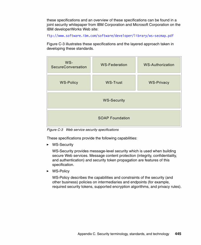
these specifications and an overview of these specifications can be found in a joint security whitepaper from IBM Corporation and Microsoft Corporation on the IBM developerWorks Web site:
ftp://www.software.ibm.com/software/developer/library/ws-secmap.pdf
Figure C-3 illustrates these specifications and the layered approach taken in developing these standards.
Figure C-3 Web service security specifications
These specifications provide the following capabilities:
� WS-Security
WS-Security provides message-level security which is used when building secure Web services. Message content protection (integrity, confidentiality, and authentication) and security token propagation are features of this specification.
� WS-Policy
WS-Policy describes the capabilities and constraints of the security (and other business) policies on intermediaries and endpoints (for example, required security tokens, supported encryption algorithms, and privacy rules).
WS-SecureConversation WS-AuthorizationWS-Federation
WS-Policy WS-Trust WS-Privacy
WS-Security
SOAP Foundation
Appendix C. Security terminology, standards, and technology 445

� WS-Trust
WS-Trust describes a framework for trust models that enables Web services to interoperate securely. This specification is responsible for managing trusts and establishing trust relationships.
� WS-Privacy
WS-Privacy describes a model for how Web services and consumers state privacy preferences and organizational privacy practice statements.
� WS-Federation
WS-Federation describes how to manage and broker the trust relationships in a heterogeneous federated environment, including support for federated identities.
� WS-SecureConversation
WS-SecureConversation describes security context exchange and establishing and deriving session keys.
WS-SecurityThe WS-Security specification provides message-level security. The advantage of using WS-Security instead of Secure Sockets Layer (SSL) is that it can provide end-to-end message level security. This means that the messages are protected even if the message goes through multiple services, or intermediaries. Additionally, WS-Security is independent of the transport layer protocol. It can be used for any SOAP binding, not just for SOAP over HTTP.
446 Understanding SOA Security Design and Implementation

As an overview, Figure C-4 shows the Web service security elements that can be added to the SOAP header.
Figure C-4 SOAP message security with WS-Security
The WS-Security specification Version 1.1 was ratified by the OASIS WSS Technical Committee in February 2006. This specification proposes a standard set of SOAP extensions. This specification is flexible and is designed to be used as the basis for securing Web services within a wide variety of security models including Public Key Infrastructure (PKI), Kerberos, and SSL. It provides support for multiple security token formats, multiple trust domains, multiple signature formats, and multiple encryption technologies to provide integrity or confidentiality.
The WS-Security specification defines the usage of XML Signature and XML Encryption:
� Message integrity is provided by XML Signature in conjunction with security tokens to ensure that modifications to messages are detected. See:
http://www.w3c.org/Signature
Misc. Headers
Security Header
SOAP Body
SOAP Header
SOAP Envelope Security Token
Timestamp
Signature
Encrypted Key
Encrypted Data
Data *
* Depending on the applied security, the data is clear text or encrypted.
Appendix C. Security terminology, standards, and technology 447

� Message confidentiality leverages XML Encryption in conjunction with security tokens to keep portions of a SOAP message confidential. See:
http://www.w3c.org/Encryption
The specification includes security token propagation, message integrity, and message confidentiality. However, these mechanisms by themselves do not address all the aspects of complete security solution. Therefore, WS-Security represents only one of the layers in a complex secure Web services solution design.
More information about the OASIS Web services Security specifications is available from:
http://www.oasis-open.org/committees/tc_home.php?wg_abbrev=wss
WS-PolicyWS-Policy provides a flexible and extensible grammar for expressing the capabilities, requirements, and general characteristics of entities in an XML Web services-based system. WS-Policy defines a framework and a model for the expression of these properties as policies. Policy expressions allow for both simple declarative assertions as well as more sophisticated conditional assertions.
WS-Policy defines a policy to be a collection of one or more policy assertions. Some assertions specify traditional requirements and capabilities that will ultimately manifest on the wire (for example, authentication scheme and transport protocol selection). Some assertions specify requirements and capabilities that have no wire manifestation yet are critical to proper service selection and usage (for example, privacy policy and QoS characteristics). WS-Policy provides a single policy grammar to allow both kinds of assertions to be reasoned about in a consistent manner.
WS-Policy stops short of specifying how policies are discovered or attached to a Web service. Other specifications are free to define technology-specific mechanisms for associating policy with various entities and resources. Subsequent specifications will provide profiles on WS-Policy usage within other common Web services technologies.
The specification that makes up WS-Policy is available for download from IBM developerWorks at:
http://www.ibm.com/developerworks/library/specification/ws-polfram/
This is an excerpt from the IBM developerWorks definition of WS-Policy.
448 Understanding SOA Security Design and Implementation

WS-TrustThe Web Services Trust Language (WS-Trust) uses the secure messaging mechanisms of WS-Security to define additional primitives and extensions for the issuance, exchange, and validation of security tokens. WS-Trust also enables the issuance and dissemination of credentials within different trust domains.
In order to secure a communication between two parties, the two parties must exchange security credentials (either directly or indirectly). However, each party needs to determine if they can trust the asserted credentials of the other party. This specification defines extensions to WS-Security for issuing and exchanging security tokens and ways to establish and access the presence of trust relationships.
The specification that makes up WS-Trust is available for download from IBM developerWorks at:
http://www.ibm.com/developerworks/webservices/library/specification/ws-trust/
This is an excerpt from the IBM developerWorks definition of WS-Trust.
WS-FederationWS-Federation describes how to use the existing Web services security building blocks to provide federation functionality, including trust, single sign-on (and single sign-off), and attribute management across a federation. WS-Federation is really a family of three specifications: WS-Federation, WS-Federation Passive Client, and WS-Federation Active Client.
WS-Federation itself describes how to implement a federation in a Web services world. In particular, WS-Federation focuses on the relationships between parties and the high-level architecture that supports these relationships. The two individual documents, WS-Federation Active and WS-Federation Passive, describe how to implement individual federation solutions.
WS-Federation Active describes how to implement federation functionality in the active client environment. Active clients are those that are Web services-enabled, that is, able to issue Web services requests and react to a Web services response. Leveraging the Web services security stack, WS-Federation Active describes how to implement the advantages of a federation relationship, including single sign-on, in an active client environment.
WS-Federation Passive describes how to implement federation functionality in a passive client environment. A passive client is one that is not Web services-enabled. The most commonly encountered example of a passive client
Appendix C. Security terminology, standards, and technology 449

is a vanilla HTTP browser. WS-Federation Passive describes how to leverage the advantages of a federation relationship such as single sign-on in a passive client environment. Because this solution leverages the WS-Security foundation of the infrastructure support, the same components used to provide a passive client solution can be leveraged for an active client solution.
The three specifications that make up WS-Federation are available for download from IBM developerWorks at:
� WS-FED:
http://www.ibm.com/developerworks/webservices/library/ws-fed/
� WS-FEDACT:
http://www.ibm.com/developerworks/webservices/library/ws-fedact/
� WS-FEDPASS:
http://www.ibm.com/developerworks/webservices/library/ws-fedpass/
The logical architecture described in WS-Federation, together with the functionality described in the Web services security stack, supports both the active and passive client scenarios. The complete family of WS-Security specifications provides companies with a standards-based interoperable secure digital identity and a trust platform for Web services-based architecture. Furthermore, these specifications promote reusability of existing IT security investments, enabling companies to work with multiple security token types and multiple scenarios, including vanilla browsers, enhanced browsers, active clients, and application-to-application connectivity.
WS-SecureConversationThe Web Services Secure Conversation Language (WS-SecureConversation) is built on top of the WS-Security and WS-Policy models to provide secure communication between services. WS-Security focuses on the message authentication model, but not a security context, and thus is subject to several forms of security attacks. This specification defines mechanisms for establishing and sharing security contexts, and deriving keys from security contexts, to enable a secure conversation.
By using the SOAP extensibility model, modular SOAP-based specifications are designed to be composed with each other to provide a rich messaging environment. Therefore, WS-SecureConversation by itself does not provide a complete security solution. WS-SecureConversation is a building block that is used in conjunction with other Web service and application-specific protocols (for example, WS-Security) to accommodate a wide variety of security models and technologies.
450 Understanding SOA Security Design and Implementation

The specification that makes up WS-SecureConversation is available for download from IBM developerWorks at:
http://www.ibm.com/developerworks/webservices/library/specification/ws-secon/
This is an excerpt from the IBM developerWorks definition of WS-SecureConversation.
WS-SecurityPolicyThe Web Services Security Policy Language (WS-SecurityPolicy) specification defines a set of security policy assertions that apply to Web Services Security: SOAP Message Security, WS-Trust, and WS-SecureConversation. This specification takes the approach of defining a base set of assertions that describe how messages are to be secured. Flexibility with respect to token types, cryptographic algorithms, and mechanisms used, including using transport-level security, is part of the design and allows for evolution over time. The intent is to provide enough information for compatibility and interoperability to be determined by Web services participants, along with all information necessary to actually enable a participant to engage in a secure exchange of messages.
The specification that makes up WS-SecurityPolicy is available for download from IBM developerWorks at:
http://www.ibm.com/developerworks/webservices/library/specification/ws-secpol/
This is an excerpt from the IBM developerWorks definition of WS-SecurityPolicy.
WS-ProvisioningWS-Provisioning describes the APIs and schema necessary to facilitate interoperability between provisioning systems and to allow software vendors to provide provisioning facilities in a consistent way. The specification addresses many of the problems faced by provisioning vendors in their use of existing protocols, commonly based on directory concepts, and confronts the challenges involved in provisioning Web services described using WSDL and XML Schema.
The WS-Provisioning interface is an open standard that is available to other companies that want to develop interoperable provisioning scenarios and systems. The specification is publicly available on the IBM developerWorks Web site:
http://www.ibm.com/developerworks/webservices/library/ws-provis/
Appendix C. Security terminology, standards, and technology 451

WS-Provisioning has been submitted to the Organization for the Advancement of Structured Information Standards (OASIS) Provisioning Service Technical Committee.
More informationBecause Web services security is a quickly evolving field, it is essential for developers and designers to regularly check for recent updates. In this section, we provide some of the most important entry points for your exploration:
� The XML Signature Workgroup home page can be found at:
http://www.w3.org/Signature/
� The XML Encryption Workgroup home page can be found at:
http://www.w3.org/Encryption/
� The WS-Security specification 1.0 can be found at:
http://www.ibm.com/developerworks/library/ws-secure/
� The whitepaper of the Web services security roadmap can be found at:
http://www.ibm.com/developerworks/webservices/library/ws-secmap/
� The OASIS WS-Security 1.0 and token profiles can be found at:
http://www.oasis-open.org/committees/tc_home.php?wg_abbrev=wss
Security Assertion Markup LanguageSecurity Assertion Markup Language (SAML) is a specification designed to provide cross-vendor single sign-on interoperability. SAML was developed by a consortium of vendors (including IBM) under the auspices of OASIS, through the OASIS Security Services Technical Council (SSTC). SAML has two major components: It describes SAML assertions used to transfer information within a single sign-on protocol and SAML bindings and profiles for a single sign-on protocol.
A SAML assertion is an XML-formatted token that is used to transfer user identity (and attribute) information from a user’s identity provider to trusted service providers as part of the completion of a single sign-on request. A SAML assertion provides a vendor-neutral means of transferring information between federation business partners. Therefore, SAML assertions have a lot of traction in the overall federation space.
452 Understanding SOA Security Design and Implementation
As a protocol, SAML has three versions: SAML 1.0, 1.1, and SAML 2.0. SAML 1.0 and SAML 1.1 (collectively, SAML 1.x) focus on single sign-on functionality. SAML 2.0 represents a major functional improvement over SAML 1.x.
As the most recent release, SAML 2.0 uses as input both the Shibboleth work and Liberty ID-FF 1.2. SAML 2.0 takes into account more of the identity life cycle functionality than previous versions. Likewise, based on the Shibboleth input, SAML 2.0 has functionality that addresses some of the privacy concerns associated with a federated environment.
More information about the SAML specification is available from:
http://www.oasis-open.org/committees/tc_home.php?wg_abbrev=security
eXtensible Access Control Markup LanguageeXtensible Access Control Markup Language (XACML) is an initiative to develop a standard for access control and authorization systems. It describes both a common language for expressing access control policies to describe general access control requirements and a request/response language that describes how to form a query to determine if a given action is allowed or not and how to interpret the result.
XACML addresses several use cases:
� Define a policy.� Gather required data for policy evaluation.� Evaluate policy.� Enforce policy.
More information about XACML can be found at the OASIS Web site:
http://www.oasis-open.org/committees/tc_home.php?wg_abbrev=xacml
Java Authorization Contract for ContainersJava Authorization Contract for Containers (JACC) was introduced in the J2EE 1.4 specification to address some problems and limitation of earlier definitions:
� All access decisions were made by the application server, unless proprietary interfaces were used for third-party plug-ins.
� There were no standards for integration of application servers with authorization service providers. There was no standard representation of application security policy (roles, resources, and resource-to-role mappings) and no standard interface for access decision (declarative or programmatic).
Appendix C. Security terminology, standards, and technology 453

JACC allows third-party authorization service providers to plug into application servers, such as WebSphere, using standard interfaces for policy configuration and access decisions. JACC defines new Permission classes to handle both the EJB and the Web permissions required by “security constraints” in J2EE deployment descriptors. A J2EE role is a named collection of these permissions.
JACC defines a standard contract (interfaces and rules) that allows authorization framework providers to plug into J2EE application containers to provide authorization policy management and access decision services. Figure C-5 shows these relationships.
Figure C-5 Java Authorization Contract for Containers (JACC)
More information about JACC can be found at:
http://java.sun.com/j2ee/javaacc/index.html
Service Provisioning Markup LanguageService Provisioning Markup Language (SPML) provides an XML framework for managing the provisioning and allocation of identity information and system resources within and between organizations. SPML V2.0 was ratified as an OASIS standard in April 2006.
Note: JACC does not specify a standard interface for principals (users and groups) to roles mapping.
JACC Provider
Policy Configuration
Provider Repository
Access Decision
J2EE ContainerApplication Management
(deploy, undeploy) Access Enforcement
Manage resources, roles, mappings Access allowed?
Application Administrator
User
454 Understanding SOA Security Design and Implementation
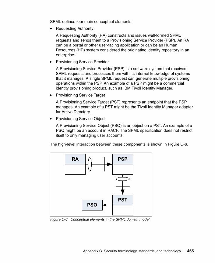
SPML defines four main conceptual elements:
� Requesting Authority
A Requesting Authority (RA) constructs and issues well-formed SPML requests and sends them to a Provisioning Service Provider (PSP). An RA can be a portal or other user-facing application or can be an Human Resources (HR) system considered the originating identity repository in an enterprise.
� Provisioning Service Provider
A Provisioning Service Provider (PSP) is a software system that receives SPML requests and processes them with its internal knowledge of systems that it manages. A single SPML request can generate multiple provisioning operations within the PSP. An example of a PSP might be a commercial identity provisioning product, such as IBM Tivoli Identity Manager.
� Provisioning Service Target
A Provisioning Service Target (PST) represents an endpoint that the PSP manages. An example of a PST might be the Tivoli Identity Manager adapter for Active Directory.
� Provisioning Service Object
A Provisioning Service Object (PSO) is an object on a PST. An example of a PSO might be an account in RACF. The SPML specification does not restrict itself to only managing user accounts.
The high-level interaction between these components is shown in Figure C-6.
Figure C-6 Conceptual elements in the SPML domain model
RA PSP
PSTPSO
Appendix C. Security terminology, standards, and technology 455
Despite the second version of SPML already being ratified as a standard, additional work is required to cater for comprehensive implementations. Examples include:
� There is no concept of ownership of PSOs.
� Workflow interactions, such as request approval, cannot be represented in SPML.
� Protocol bindings to transports are not well-defined at this time. Integration with development tools is limited, and achieving interoperability is then based on interaction contracts beyond the SPML standard.
� Securing SPML messages is not well-defined.
For more information about SPML and its progress as an evolving standard, consult the OASIS Provisioning Services Technical Committee site:
http://www.oasis-open.org/committees/tc_home.php?wg_abbrev=provision
z/OS securityz/OS security can be grouped into two major base components:
� The System Authorization Facility (SAF)� RACF
System Authorization FacilityThe System Authorization Facility is part of the z/OS operating system and provides the interfaces to the callable services provided to perform authentication, authorization, and audit logging.
SAF does not require any other product as a prerequisite, but overall system security functions are greatly enhanced and complemented if it is used concurrently with RACF. The key element in SAF is the SAF router. This router is always present, even when RACF is not present.
The SAF router provides a common focal point for all products providing resource control. This focal point encourages the use of common control functions shared across products and across systems. The resource managing components and subsystems call the SAF router as part of the decision-making functions in their processing, such as access-control checking and authorization-related checking. These functions are called control points.
456 Understanding SOA Security Design and Implementation

The system authorization facility (SAF) conditionally directs control to RACF (if RACF is present) or to a user-supplied processing routine, or both, when receiving a request from a resource manager.
Figure C-7 shows the basic functionality of SAF.
Figure C-7 System Authorization facility
RACFResource Access Control Facility (RACF) is an add-on software product that provides security for a mainframe system.
RACF protects resources by granting access only to authorized users of the protected resources. RACF retains information about users, resources, and access authorities in special structures called profiles in its database, and it refers to these profiles when deciding which users should be permitted access to protected system resources.
To accomplish its goals, RACF gives you the ability to:
� Identify and authenticate users
� Authorize users to access protected resources
� Log and report various attempts of unauthorized access to protected resources
� Control the means of access to resources
� Allow applications to use the RACF macros
RACFcheck
Optional exit
RACF call
Exit RC
RACF RC
Exit check
S
A
F
RACROUTE
SAF callable services
YES / NO
Database
Appendix C. Security terminology, standards, and technology 457

RACF uses a user ID and a system-encrypted password to perform its user identification and verification. The user ID identifies the person to the system as a RACF user. The password verifies the user’s identity. Often exits are used to enforce a password policy, such as a minimum length, lack of repeating characters, or adjacent keyboard letters, and also the use of numerics as well as letters.
To get an cursory understanding of how authorization works and to explain the communications involved, an authorization check is performed the following way (see Figure C-7 on page 457):
1. A user requests access to a resource using a resource manager.
2. The resource manager issues a RACROUTE request to see if the user can access the resource.
3. RACF refers to the RACF database or in-storage data.
4. RACF retrieves data for the profile.
5. Based on the information in the profile, RACF passes the resulting status code for the request to the resource manager.
6. The resource manager grants or denies the request.
RACF does not decide whether the request is granted or not. It returns a status code to the resource manager, and the resource manager makes the decision. RACF will return one of four status codes meaning:
� The user has the access right.
� The user does not have access.
� It is unknown whether the user has the access right or not.
� RACF is not working.
The resource manager uses this return code to make a decision.
An alternative to the RACF password provided by the RACF secured sign-on function is the Passticket. The RACF Passticket is a one-time-only password that is generated by a requesting product or function. It is an alternative to the RACF password that removes the need to send RACF passwords across the network in clear text. It makes it possible to move the authentication of a mainframe application user ID from RACF to another authorized function executing on the host system or to the work station local area network (LAN) environment.
458 Understanding SOA Security Design and Implementation

Tip: To learn more about SAF and how it works with RACF, you can look in:
� OS/390® SecureWay® Security Server RACROUTE Macro Reference
http://publibz.boulder.ibm.com/epubs/pdf/ich1c610.pdf
� OS/390 SecureWay Security Server RACF Callable Services
http://publibz.boulder.ibm.com/epubs/pdf/ich1d121.pdf
To learn more about Passticket, refer to Chapter 11, “The RACF Secured Signon PassTicket”, in z/OS V1R4.0 Security Server RACF Macros and Interfaces, SA22-7682, found at:
http://publibz.boulder.ibm.com/epubs/pdf/ichza330.pdf
Appendix C. Security terminology, standards, and technology 459

460 Understanding SOA Security Design and Implementation

Appendix D. Additional material
This IBM Redbooks publication refers to additional material that can be downloaded from the Internet as described below.
Locating the Web materialThe Web material associated with this IBM Redbooks publication is available in softcopy on the Internet from the IBM Redbooks Web server. Point your Web browser to:
ftp://www.redbooks.ibm.com/redbooks/SG247310
Alternatively, you can go to the IBM Redbooks Web site at:
ibm.com/redbooks
Select Additional materials and open the directory that corresponds with the IBM Redbooks publication form number, SG247310.
Using the Web materialThe additional Web material that accompanies this IBM Redbooks publication includes the following files:
File name Description
D
© Copyright IBM Corp. 2007. All rights reserved. 461

SG247310.zip See details below
The zip file contains files for the two scenarios presented in this book. Create a subdirectory (folder) on your workstation and unzip the contents of the Web material zip file into this subdirectory (folder).
Example 1 - CICSChapter 9, “Technical implementation” on page 181 provides detailed instructions about how to use these files:
certs/ Directory containing key stores for ITSOTelco and ITSOBank components used in the example.
jaas-module/ Directory containing the JAAS login module that calls the Tivoli Federated Identity Manager Security Token Service.
ldap-sts-module/ Trust service module for identity mapping using LDAP.
mapping-rules/ Directory containing mapping rules for TFIM trust service and transforms used in configuring the XML firewall in the solution.
bank2005.zip This file contains the CICS portion of the scenario. See more information in the next section.
ITSOBanker2007.ear Bank Web service with security added.
ITSOTelcoPortal2007.earBank Web service client with no security.
Installing the CICS portion of the ITSOBank scenarioPerform the following tasks:
1. Unzip the supplied bank2005.zip to a temporary directory.
2. On the z/OS side, create a partitioned dataset library with the FB80 format for the source files.
3. Upload all the files from the bank2005.zip as members to this dataset. You can ignore the extensions. The members would be:
DPLCSHOW Assembler source for 3270 transaction
DPLCMAP CICS map source
DPLC Main C program source
ACCTBNTB SPUFI source for account table
EMPLOYEE SPUFI source for employee data
CSDUP CICS resource definition source
462 Understanding SOA Security Design and Implementation

4. Compile the program and map the source into a load library that is concatenated to the CICS’s DFHRPL:
– DPLCMAP can be compiled using the procedure DFHMAPS or DFHMAPT.
– DPLCSHOW can be assembled and link-edited using the procedure DFHEITAL.
– DPLC must be compiled through the DB2 pre-processor and the CICS translator. You can use the supplied DB2 sample DSNHC procedure and invoke the CICS procedure DFHYITDL.
5. Create DB2 tables. You might need to work with a DB2 administrator to perform this task. The sample SPUFI files will create the tables on the public database DSNDB04 using the default storage group. Run SPUFI using the EMPLOYEE source and then the ACCTBNTB. All return codes should be 0000.
6. Create a CICS resource definition using the source CSDUP. This creates a group called BANK2005. You should include this group into the startup list for the CICS initialization to be automatically installed when you start CICS. You can interactively install the group using the CEDA INSTALL GROUP(BANK2005) command from a CICS session.
7. Test the transaction by invoking DPLS. You should receive miscellaneous data as shown in Figure D-1.
Figure D-1 CICS DPLC output
Appendix D. Additional material 463

8. To prepare the connection from the CICS Transaction Gateway, you must define the necessary resources for the CICS Transaction Gateway to access this CICS. Additional definitions must include CONNECTION and SESSION resources.
Example 2 - WebSphere ESBChapter 12, “Technical implementation” on page 333 provides detailed instructions about how to use these files.
464 Understanding SOA Security Design and Implementation

Related publications
The publications listed in this section are considered particularly suitable for a more detailed discussion of the topics covered in this IBM Redbooks publication.
IBM Redbooks publicationsFor information about ordering these publications, see “How to get IBM Redbooks publications” on page 466. Note that some of the documents referenced here may be available in softcopy only.
� Develop and Deploy a Secure Portal Solution Using WebSphere Portal V5 and Tivoli Access Manager V5.1, SG24-6325
� Enterprise Business Portals II with IBM Tivoli Access Manager, SG24-6885
� Enterprise Security Architecture Using IBM Tivoli Security Solutions, SG24-6014
� Federated Identity Management and Web Services Security with IBM Tivoli Security Solutions, SG24-6394
� IBM Tivoli Composite Application Manager V6.0 Family: Installation, Configuration, and Basic Usage, SG24-7151
� IBM WebSphere Application Server V6.1 Security Handbook, SG24-6316
� Patterns: SOA Foundation - Business Process Management Scenario, SG24-7234
� Patterns: SOA Foundation Service Connectivity Scenario, SG24-7228
� Web Services Handbook for WebSphere Application Server 6.1, SG24-7257
� WebSphere Version 6 Web Services Handbook Development and Deployment, SG24-6461
© Copyright IBM Corp. 2007. All rights reserved. 465

Other publicationsThese publications are also relevant as further information sources:
� Lansiti, et al., The Keystone Advantage: What the New Dynamics of Business Ecosystems Mean for Strategy, Innovation, and Sustainability, Harvard Business School Publishing, Press, 2004, ISBN 1591393078
� “Daimler’s New Way to Make Cars: Let Someone Else Do It”, in Forbes, August 16, 2004
� IBM Tivoli Federated Identity Manager Web Services Security Management Guide Version 6.1.1, GC32-0169-01
Online resourcesThese Web sites are also relevant as further information sources:
� The Web services security model introduces a set of individual interrelated specifications to form a layered approach to security. An overview of these specifications can be found on the IBM developerWorks site:
ftp://www.software.ibm.com/software/developer/library/ws-secmap.pdf
� Many open standards in the areas of security, SOA, Web Services, and similar topics are documented at the Organization for the Advancement of Structured Information Standards (OASIS):
http://www.oasis-open.org
How to get IBM Redbooks publicationsYou can search for, view, or download IBM Redbooks publications, IBM Redpapers, Hints and Tips, draft publications and Additional materials, as well as order hardcopy IBM Redbooks publications or CD-ROMs, at this Web site:
ibm.com/redbooks
Help from IBMIBM Support and downloads
ibm.com/support
IBM Global Services
ibm.com/services
466 Understanding SOA Security Design and Implementation
Index
Symbols.NET
service consumer 69
Aaccess
management 25, 109policy management 26, 28, 38
Access Manager 432transport level security 171
Access Manager for e-businessaudit 174authorization 81authorization audit 169JACC provider 169policy decision and enforcement 178, 330Service Connectivity scenario authorization 95Service Creation scenario 164
Access Manager for Operating Systemsfile system protection 326protection for data at rest 171
Access Services 422account
re-certification 154accountability 4
... for identity propagation 21anomaly detection 41
ISS Proventia 123approach to creating service
bottom-up 412top-down 412
approval 38architectural pattern
Business Process Management 128architectural policy 49architecture decision guide 59assemble 418
life cycle 15audit 13, 22, 28, 35, 61, 71, 154, 444
authorization decisions 169Common Base Event 142ESB 90policy 45
© Copyright IBM Corp. 2007. All rights reserved.
Audit Services 45, 83, 98, 122, 142, 173, 326authenticated identity 23authentication 20, 22, 442
mechanisms 106strong ... 119Trust Association Interceptor 321Web service 153, 165
Authentication Services 43, 79, 94, 118, 138, 165, 321
externalization 119authorization 20, 27, 154, 443
ESB 90mediation for ESB 96policy 44role based 81Web service 165
Authorization Services 43, 80, 95, 120, 139, 168, 324automation of business processes 126availability 444
Bbiometric authentication 43bottom-up 412boundary service 12BPEL 129business
compliance 36context 3examples 3policy 49requirements 16, 153, 397trust management 38
Business Application Services 422Business Innovation Services 423business process
decomposition 6security 441
Business Process and Policy Management 124Business Process Execution Language
see BPELBusiness Process Execution Language for Web Services 413
467

Business Process Management scenario 125, 436architectural pattern 128Business Security Services 132Governance and Risk Management 143identity provisioning 135IT Security Services 133Security Enablers 142Security Policy Management 143security requirements 130
Business Security Services 33, 35, 57, 144, 159, 315
Business Process Management scenario 132Interaction and Collaboration Services scenario 107Service Connectivity scenario 91Service Creation scenario 72, 159
CCBE 45CERT 40CICS 427
audit 174Connection Factory 256identity mediation 284resource adapter 254Web service exposure 150
CICS Transaction Gateway 428authentication 154security token exchange 168transport level security 171
CMDB 47Collaboration Scenario
example 5COMMAREA 428Common Base Event 142
see CBEcommunication
ESB 88compliance 4–5, 9, 13, 15, 19, 61, 444
human tasks 132management 35objective 107
Compliance and Reporting 72, 91, 107, 132, 160, 315Compliance Insight Manager 83, 122, 132
Service Connectivity scenario 315, 327–328Service Creation scenario 160, 173, 175
component based application 399
componentization 7composite application 12, 395, 426Computer Emergency Response Team
see CERTconfidentiality 20, 22, 443
ESB 90Confidentiality and Integrity Services 82, 97, 141, 170Confidentiality Services 44, 82, 97, 121, 170, 325configuration management database
see CMDBconsume Web service 412consumer 440
portal 20cryptographic
cipher strength 110key store 108services
Service Creation scenario 175cryptography 47CTG
See CICS Transaction Gateway
Ddata
... at rest 13, 36, 71, 443
... in process 443
... in transit 4, 13, 36, 71, 172, 443delivery 37encryption 36, 443format translation 8origin 37protection 13, 31, 36, 82, 97
Data Protection and Disclosure Control 73Data Protection, Privacy and Disclosure Control 73, 91, 108, 132, 160, 316DataPower 90
appliance 159, 166audit 174Federated Identity Manager STS 94policy decision and enforcement 177Toolkit 432XS40 432
configuration 210, 266loopback mode 213SSL configuration 215
DB2encryption 82
468 Understanding SOA Security Design and Implementation

declarative security 19enforcement 46
decomposition... of business processes 6
defense in depth 60delivery of data 37deploy 418
life cycle 15deployment architecture 22Development Services 424digital signature 37, 45, 444Direct Exposure Architectural Pattern 68directory 47disclosure control 36discovery 396dynamic invocation 412dynamic proxy 412
EEclipse 402EDI
security 37EIS
See Enterprise Information SystemEJB container 412Electronic Data Interchange
see EDIencryption 45, 443Enterprise Architect 420Enterprise Information System 427enterprise service bus
see ESBenterprise transformation 427ESB 5, 19, 314, 334, 423
characteristics 88identity mapping 92message protection policies 99policy enforcement point 44security requirements 90
examplebusiness case 3Collaboration 5Service Connectivity 5Service Creation 4
existing assets 4expose J2EE artifact as service
servlet 412stateless session EJB 412
expose Web services 411eXtensible Access Control Markup Language
see XACMLExtensible Markup Language
See XML
Ffederated
identity management 61provisioning 42, 77, 93, 113single sign-on 21, 103–104, 113, 117
Federated Identity Manageraudit 174identity mediation 231policy decision and enforcement 177, 330Security Token Service 79, 93, 165, 187, 260
trace 296Service Connectivity scenario 315Service Creation scenario 164Service Creation scenario configuration 265token generator 203transport level security 170trust chain configuration 203, 362Web Services Security Management 201
financial regulations 4flexible architecture 398flow control 8
GGateway 431getting started 403, 405global security 164Governance
See SOA Governancegovernance 5, 13, 19, 56
activities 124Governance and Risk Management 58, 86
Business Process Management scenario 143Interaction and Collaboration Services scenario 124Service Connectivity scenario 99, 331Service Creation scenario 179
GSKitkey generation 182
Hhardening 41, 108
Index 469

ESB 90high availability 444HR identity feed 38human tasks 132
IIBM CICS Transaction Server
see CICSIBM Global Security Kit
see GSKitIBM Rational Application Developer
see Rational Application DeveloperIBM Service Integration Maturity Model 405IBM SOA Foundation 408
scenarios 18IBM SOA Security Reference Model 56, 72, 91, 107, 132, 158
IBM product mapping 62Service Connectivity scenario 314Service Creation scenario 159
IBM Tivoli Access Manager for e-businesssee Access Manager for e-business
IBM Tivoli Access Manager for Operating Systemssee Access Manager for Operating Systems
IBM Tivoli Compliance Insight Managersee Compliance Insight Manager
IBM Tivoli Composite Application Manager for SOA 432–434IBM Tivoli Directory Integrator
see Tivoli Directory IntegratorIBM Tivoli Federated Identity Manager
see Federated Identity ManagerIBM Tivoli Identity Manager
see Identity ManagerIBM Tivoli Security Operations Manager
see Security Operations Manageridentity 20, 441
approval process 109end-to-end flow 80ESB 90federation 113feed 38foundation 93, 111, 134, 162, 318management 26, 62, 108, 112mapping 21, 24, 78, 154, 164, 442
... in an ESB 92mediation 90, 94, 184, 231propagation 5, 8, 10, 19, 21, 23, 78, 93, 106,
113, 136, 164, 320provider 113provisioning 42, 71, 75, 93, 109, 112, 135, 163, 319
approval 38revalidation 38, 107synchronization 111token 43
definition 442translation 24
validation 22Identity and Access 37, 73, 92, 108, 133, 160, 316Identity Manager
audit 174policy decision and enforcement 178, 331Service Creation scenario 160, 163transport level security 171user provisioning 76
Identity Services 42, 74, 93, 111, 162, 318IMS 427Indirect Exposure Architectural Pattern 70Information as a Service scenario 437Information Services 422Infrastructure Services 424insurance company
business scenario 4integrity 22, 154, 443
... of messages 45ESB 90
Integrity Services 45, 83, 98, 122, 171, 326Interaction and Collaboration Services scenario 20, 101, 436
Business Security Services 107Governance and Risk Management 124IT Security Services 111Security Enablers 123Security Policy Management 123security requirements 106Web Services perspective 105Web single sign-on perspective 103
Interaction Services 422inter-organization interaction 11intrusion
detection 41, 48prevention 48protection 84
invoking Web services 412ISS Proventia solutions 84, 123, 176, 328IT Security Services 34, 41, 57, 74
470 Understanding SOA Security Design and Implementation

Business Process Management scenario 133Interaction and Collaboration Services scenario 111Service Connectivity scenario 92, 318Service Creation scenario 162using the ... 45
IT service management 424IT system life cycle 14
JJ2EE 402, 427
audit 175authorization 81deployment descriptor 46role based authorization 169
JAASlogin module 260–261, 284
JACCoverview 453provider 169
Java Authorization Contract for Containerssee JACC
Java Connector Architecturesee JCA
JAX-RPC 412JCA
resource adapter 254
KKerberos 43key management 47Key Management services
Service Creation scenario 175key store 182
LLDAP
mapping module 278life cycle 14, 417
management 38security 14
Local integration 432logical architecture
SOA security 33logical deployment architecture 22LTPA
identity token 134
Mmalware 48
detection 41manage life cycle 15mapping
... of identity 442
... of security context 71identity 23, 78module 278
masquerading 172mediation
enterprise service bus 5ESB model 89flow 335
messageauthentication 45
code 444confidentiality 448integrity 45, 154, 448protection 31, 82–83
policy 36, 99, 176, 329security 5
Message Brokers Toolkit 436message level security 20, 32, 71, 172, 446Methodology 403model 417
life cycle 15model-driven development 403Monitoring and Reporting 55, 178, 331monolithic business application 399
Nnonce 45non-disclosure 44Non-repudiation Services 37, 73, 91, 108, 133, 160
Ooperating system
hardening 41, 108operation policy 49optimization of business processes 126Optimization Services 423origin of data 37
PPartner Services 422passticket 78, 115, 122, 260
Index 471

passwordmanagement policy 37policy 109synchronization 77
patch management 41Patterns 403PDP 44, 55, 330
Service Creation scenario 177PEP 44, 51, 55, 330
externalization 119Service Creation scenario 177
Personally Identifiable Information 44, 443pluggable security 152point of contact 104
authorization 120identity propagation 113identity provisioning 106
policyabstraction level 49based provisioning 76decision 55distribution 51domain 50enforcement 55management 13, 26, 49, 154
life cycle 49reference model 51
message protection 99privacy 108provisioning 93
Policy Administration 52, 176, 329Policy Decision and Enforcement 55, 177, 330Policy Decision Point
see PDPPolicy Distribution and Transformation 53, 177, 330Policy Enforcement Point
see PEPPolicy Management 58portal 20
service consumer 69privacy 20, 443
management 36policy 36, 44, 108
Process modeling 403Process Services 422profile management 21programmatic security enforcement 46programming model
IT Security Services 45
propagation 21, 78... of identity 10
provider policy 177, 329provisioning 42, 75, 109, 112
... of identities 93federation 77identity 23policy 42, 93
Public Key Infrastructure 108, 182
Qquality of service
ESB 89
RRACF
authentication 154authorization 81identity mapping 154JAAS login module 260–261overview 457passticket 115, 122, 260
generation 281policy decision and enforcement 178
Rational Application Developer 184adding WS-Security to application 237
re-authentication 119re-certification 154Redbooks Web site 466
Contact us xviReference architecture 403reference model for policy management 51regulatory compliance 13reporting 35, 55request based provisioning 42request consumer
configuration 352request generator
configuration 185, 347requirements
security management 16Resource Access Control Facility
see RACFResource Adapter Module 254response consumer
configuration 193reuse 9revalidation 38
472 Understanding SOA Security Design and Implementation

of identities 107risk management 25, 56, 107, 179, 331role based authorization 81, 169
SSAF
see System Authorization FacilitySAML
assertion 43, 116, 155identity token 442overview 452security token conversion 238Signature Validation Credentials 225token generator 188
SCASee Service Component Architecture
scenarioBusiness Security Services 159Confidentiality and Integrity Services 170technical implementation 181
SDOSee Service Data Objects
secure sockets layersee SSL
Secure Systems and Networks 40, 73, 92, 110, 133, 161, 317security
context mapping 71enforcement 45ESB 89infrastructure integration challenge 23logical architecture for SOA 33management 9
challenge 10, 23high level requirements 16
message-level 32policy 10, 14, 112, 440
distribution 51management 13, 51, 444
requirementsInteraction and Collaboration Services sce-nario 106
role references 411services
standards 47token 21, 43, 155
definition 443exchange 166
propagation 448service 78
Security Assertion Markup Languagesee SAML
Security Enablers 58, 84Business Process Management scenario 142Interaction and Collaboration Services scenario 123Service Connectivity scenario 98, 328Service Creation scenario 175
Security Operations Manager 176Service Connectivity scenario 328
Security Policy Management 34, 58, 84Business Process Management scenario 143Interaction and Collaboration Services scenario 123Monitoring and Reporting 55Policy Administration 52Policy Decision and Enforcement 55Policy Distribution and Transformation 53Service Connectivity scenario 99, 329Service Creation scenario 176
Security Reference Model 56Security Token Service
see STSSEI
See service endpoint interfaceself-care 21, 38self-service 77separation of duties 46service 394
authorization 168compliance 13component 150componentization 7composite application 12consumer 396, 440definition of ... 6endpoint interface 411ESB interaction 88implementation bean 411infrastructure 8orientation 6, 394
life cycle 14provider 395registry 47, 396reuse 9security 441
considerations 9
Index 473

management challenges 10specification 88
Service Component Architecture 129, 402implementation policy 141interaction policy 141role based security model 131security model 139
Service Connectivity scenario 19, 87, 429audit 98business context 307Business Security Services 91, 315example 5Governance and Risk Management 99, 331IBM SOA Security Reference Model 314IT context 309IT Security Services 92, 318mediation flow 335PDP 330PEP 330realizations
Gateway 431Local integration 432
Security Enablers 98, 328Security Policy Management 99, 329security requirements 90SOA Governance Board 331SOA Security Reference Model 91solution design 313technical implementation 333
Service Creation scenario 18, 67, 426Access Manager for e-business authorization 168architectural pattern 68audit 173, 175authorization 80business requirements 153Business Security Services 72, 159CICS
Connection Factory 256identity mediation 284resource adapter installation 254
deploy the application 200example 4Governance and Risk Management 179IBM SOA Security Reference Model 72identity foundaion 74identity mediation configuration 237IT infrastructure 149IT Security Services 162
JAAS login module 260–261, 284key store 182LDAP mapping module configuration 278message protection enabling 237RACF passticket generation 281realizations 427
Consume services 429Create Web service from WSDL 428Direct exposure 427Indirect exposure 428
request consumer configuration 238response generator configuration 247risk management 179Security Enablers 84, 175Security Policy Management 84, 176security requirements 70service
authorization 168consumer types 69
SOA Governance Board 179solution overview 158transport level security 170Web services security 184
Service Data Objects 402service level
authorization 81, 96ESB 89
Service Level Agreements 426Service Provisioning Markup Language
see SPMLService Registry and Repository
see SRRService-oriented Architecture
See SOAsession management services 119shift in IT driven by business 401signature 37, 45SIMM 405Simple Object Access Protocol
See SOAPsingle sign-off 449single sign-on 21, 60, 103, 449SLA
See Service Level AgreementSOA 393–394
... based application 400Adoption 402, 405applications 17Assessment Tool 405
474 Understanding SOA Security Design and Implementation

business requirements 397challenges 396compliance management 30, 35components
service consumer 396service provider 395service registry 396
definedby role 394composite application 395service 394service orientation 394
Design 425drivers 397
achieve better IT use and ROI 398need for flexible architecture 398reduce cycle time and costs 398simplify integration across the enterprise 398support an agile business model 397
example approach 403getting started 405
IBM SOA Entry Points 406IBM SOA Foundation 408SOA Adoption 405
Governance 56, 402, 419, 426life cycle implementation 182, 334logical deployment architecture 22risk management 56, 58security 440
architecture decision guide 59audit 444authentication 442authorization 443availability 444compliance 444confidentiality 443governance 56identity 441integrity 443logical architecture 18, 33policy
management 444privacy 443reference model 72, 91, 107, 132, 158
Security Reference Model 56IBM product mapping 62
Web services 413why now
best practices 402open standards and platforms 402shift in IT driven by business 400SOA enables flexibility 401
SOA Entry Points 406Connectivity 407Information 407People 406Process 407Reuse 407
SOA Foundationarchitecture layers 426life cycle 416
Assemble 418Deploy 418Manage 419Model 417
Reference Architecture 420Access services 422Business application services 422Business innovation services 423Development services 424Enterprise Service Bus 423Information Services 422Interaction services 422Middleware Services view 421Optimization services 423Partner services 422Process services 422Solution view 420
scenarios 18, 424Business Process Management 125, 436Information as a Service 437Interaction and Collaboration 20Interaction and Collaboration Services 101, 436Service Connectivity 19, 87, 429Service Creation 18, 67, 426
SOAP 409binding 32, 446body 409encoding rules 409envelope 409headers 409message
details 172format 409security 447
policy assertions 54
Index 475

RPC representation 409transports 409
SPML 77, 93overview 454
SRR 51SSL 32, 121, 170
message protection 82transport level security 97
SSOsee single sign-on
standardssecurity services 47
static stub 412strong authentication 119STS
identity mapping 115, 136identity propagation 136, 320
submission of data 37swivel chair management 13synchronization
identity 111passwords 77user repository 93
System Authorization Facility 152, 456systems management 9
Ttechnical implementation 181technology
trust management 38Tivoli Directory Integrator 75Tivoli Directory Server 78, 84, 123, 134
transport level security 171token
based authentication 43exchange mediation 334mediation 164
top-down 412transaction
auditing 13transport level
protection 31security 71, 154
transport of data 37trust
chain configuration 203infrastructure 108inter-organization interaction 11
management 25relationship 5, 10, 12, 19, 72
loosely coupled 40tightly coupled 39
service chain 165–166, 266Trust Association Interceptor 321Trust Management 38, 73, 92, 109, 133, 160, 317
UUDDI 410Universal Description, Discovery, and Integration
See UDDIuser
productivity 102registry
synchronization 75repository 42, 93
synchronization 93self-service 77
username token 43
Vvulnerability assessment 41
WWeb service 402, 408
... and SOA 413authentication 165authorization 165core elements
SOAP 409UDDI 410WSDL 409XML 409
gateway 159J2EE 411security specifications 445standards 410, 444technologies 408WS-Federation 449WS-Policy 448WS-Provisioning 451WS-Security 32, 446WS-SecurityPolicy 451WS-Trust 449
Web ServicesSecurity Management 201
476 Understanding SOA Security Design and Implementation
Web servicessecurity
Service Creation scenario 184Web Services Description Language
see WSDLWeb Services for Remote Portlets 106
see WSRPWeb services Interoperability Organization 410WebSphere Application Server 78, 80
audit 174deploying an application 201global security 164JACC
provider 169message level security 173policy decision and enforcement 178, 330Resource Adapter Module 254security token exchange 167
WebSphere Business Modeler 127WebSphere Business Monitor 128WebSphere DataPower
see DataPowerWebSphere ESB 90, 423, 433
Federated Identity Manager STS 94mediation 335Token Exchange Mediation Primitive 321
WebSphere Information Services Director 129authentication 135
WebSphere Integration Developer 127, 129, 433–434
WebSphere ESB integration 335WebSphere Message Broker 90, 423
Federated Identity Manager STS 94WebSphere Portal 78
authorization 81security token service 116
WebSphere Process Server 127SCA interface 130Service Component Architecture 129
WebSphere Service Registry & Repository 98WS-BPEL
See Business Process Execution Language for Web Services
WSDL 409, 413definition 411SCA interface 130
WSEE 411WS-Federation 449WS-Policy 51, 53, 85, 448
WS-Provisioning 26, 77, 93, 451WSRP 21WS-Security 32, 121, 444, 446
authentication 134encryption 122header 80integrity 83message level security 97message protection 82Roadmap 446Web site 452
WS-SecurityPolicy 53, 451WS-Trust 26, 94, 449
Security Token Service 165
XXACML 52–54
overview 28, 82, 453XML 409
encryption 84, 448Web site 452
firewall 159firewall configuration 210, 266security 60signature 84, 447
Web site 452
Zz/OS
RACF 457RACF passticket generation 281security 456System Authorization Facility 152, 456
Index 477

478 Understanding SOA Security Design and Implementation

(1.0” spine)0.875”<
->1.498”
460 <->
788 pages
Understanding SOA Security Design and Im
plementation


®
SG24-7310-01 ISBN 0738486655
INTERNATIONAL TECHNICALSUPPORTORGANIZATION
BUILDING TECHNICALINFORMATION BASED ONPRACTICAL EXPERIENCE
IBM Redbooks are developed by the IBM International Technical Support Organization. Experts from IBM, Customers and Partners from around the world create timely technical information based on realistic scenarios. Specific recommendations are provided to help you implement IT solutions more effectively in your environment.
For more information:ibm.com/redbooks
UnderstandingSOA SecurityDesign and ImplementationIntroducing an SOA security reference architecture
Implementing scenarios based on the IBM SOA Foundation
Deploying SOA using IBM Tivoli security solutions
Securing access to information is important to any business. Security becomes even more critical for implementations structured according to service-oriented architecture (SOA) principles, due to loose coupling of services and applications, and their possible operations across trust boundaries. To enable a business so that its processes and applications are flexible, you must start by expecting changes in both to process and application logic, as well as to the policies associated with them. Merely securing the perimeter is not sufficient for a flexible on demand business.
In this IBM Redbooks publication, security is factored into the SOA life cycle reflecting the fact that security is a business requirement, and not just a technology attribute. We discuss an SOA security model that captures the essence of security services and securing services. These approaches to SOA security are discussed in the context of some scenarios and observed patterns. We also discuss a reference model to address the requirements, patterns of deployment, and usage, and an approach to an integrated security management for SOA.
This IBM Redbooks publication is a valuable resource to senior security officers, architects, and security administrators.
Back cover