underwater 100 flow - rpc.com.au · pdf filepropeller aligned to face the flow. also check for...
TRANSCRIPT
Date: 7 Dec 2010 UW-100 Manual
CD: 2240
Issue: 1.2 Page 1 of 20
© Ampair®, June 2008 www.ampair.com Page 1 of 20
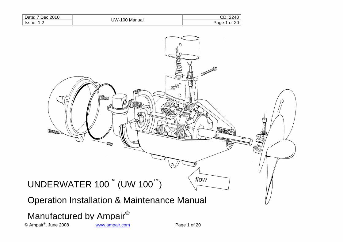
UNDERWATER 100™
(UW 100™
)
Operation Installation & Maintenance Manual
Manufactured by Ampair®
flow

Date: 7 Dec 2010 UW-100 Manual
CD: 2240
Issue: 1.2 Page 2 of 20
© Ampair®, June 2008 www.ampair.com Page 2 of 20
SAFETY: READ BEFORE ASSEMBLING OR USING ............................................................... 3
Use ........................................................................................................................................ 3 Connection ............................................................................................................................ 3 Protection .............................................................................................................................. 3
PACKING LIST: PRE-INSTALLATION CHECK ......................................................................... 3 SYSTEM DESCRIPTION .......................................................................................................... 4
Introduction ............................................................................................................................ 4 Name –Aquair; Aquair UW; Underwater; and UW .................................................................. 4 The alternator ........................................................................................................................ 4 Sealing .................................................................................................................................. 4 Additional internal protection .................................................................................................. 4 Rectification ........................................................................................................................... 4 Figure 1: Circuit diagram........................................................................................................ 4
INSTALLATION ......................................................................................................................... 4 Pre installation ....................................................................................................................... 4 Installation of UW (general) ................................................................................................... 4 Mechanical installation ........................................................................................................... 4 Figure 2: Dimensional drawing .............................................................................................. 5 Mounting ................................................................................................................................ 5 Protection .............................................................................................................................. 5 Figure 3: Protection options ................................................................................................... 6 Electrical installation .............................................................................................................. 7 Electrical fault finding ............................................................................................................. 8
OPERATION ............................................................................................................................. 8 Figure 4: Performance curves ................................................................................................ 9
CHARGE CONTROL REGULATOR ........................................................................................ 10 Installation of charge control regulator ................................................................................. 10 Figure 5: Charge control regulators ..................................................................................... 12
UW MAINTENANCE ............................................................................................................... 13 Preventative maintenance ................................................................................................... 13 Propeller removal................................................................................................................. 13 Seal change......................................................................................................................... 13 UW disassembly .................................................................................................................. 13 Removal of stators ............................................................................................................... 14 Reassembly ......................................................................................................................... 14 Testing ................................................................................................................................. 15
COMPONENT PARTS DRAWING .......................................................................................... 16 Figure 6: Component parts drawing ..................................................................................... 16 Key to component parts drawing .......................................................................................... 17
WARRANTY ............................................................................................................................ 17 SERVICING & REPAIRS ......................................................................................................... 17

Date: 7 Dec 2010 UW-100 Manual
CD: 2120
Issue: 1.2 Page 3 of 20
© Ampair®, June 2008 www.ampair.com Page 3 of 20
SAFETY: READ BEFORE ASSEMBLING OR USING Use
On sail boats, avoid sailing through coral or weed with the UW lowered.
Connection
NEVER CONNECT WITHOUT RECTIFIERS
The generator must never be connected to a system without its rectifiers in circuit, to do so risks discharging the battery to which it is connected.
CORRECT CONNECTION
It is important to connect the system in such a way that the generator cannot feed any electrical load without the battery being connected. The generator output should therefore go to the battery side of any isolator switch. Failure to observe this point could place over-voltage on the system and damage sensitive electronic equipment.
Protection
PROTECTING THE SYSTEM
Do not omit the fitting of fuses, simple in-line fuse carriers maybe used in the battery line. Fuses = 10 Amp - 12V systems: 5 Amp - 24V systems
OBSERVE POLARITY
Reverse polarity will blow the battery fuse or destroy the rectifiers if no fuse is fitted. The rectifier will be destroyed faster than a fuse can blow.
DISCONNECTING THE GENERATOR
When disconnecting the generator please be aware that when it is spinning, the output voltage, in the absence of a battery, will rise. This can give a mild electric shock to a person handling the connections.
WHEN TO FIT A REGULATOR
It is advisable to fit a voltage regulator if the UW is regularly left to charge batteries when no loads are present and the system is not being monitored. Under these conditions overcharge will slowly drive off the battery electrolyte, which, if not topped up, will eventually damage the batteries. So a regulator must always be installed if the system is not monitored or is unattended.
CAUTION
When planning your installation, observe the following: 1. Avoid operating the UW generator continuously at maximum output. Try to judge a
suitable power level, which takes account of seasonal flow variations, storm effects and possible short-term surges. Higher water speeds generate little additional power, but put excessive force on the propeller, generator and its mounting and can cause vibration and fatigue damage. If left running continuously at excessive speed the propeller can be shaken free and may damage the shaft and shaft seals.
2. Regularly inspect a newly installed system to check that all is well. Do not limit this to monitoring the electrical output, but also check for smooth mechanical operation with propeller aligned to face the flow. Also check for propeller wobble and generator vibration. Any defects need to be remedied immediately.
3. Finally, connect a safety line (well clear of the propeller) to save the generator should it become detached from its mounting.
PACKING LIST: PRE-INSTALLATION CHECK Have you received the correct voltage rating, 12V or 24V?
CHECK THAT YOU HAVE:
1 x UW generator fitted with: 1 x propeller standard type 1 x rectifier/heat-sink assembly
1 x M8 stainless steel socket cap screw with shake-proof washer 1 x 6mm hex socket wrench

Date: 7 Dec 2010 UW-100 Manual
CD: 2240
Issue: 1.2 Page 4 of 20
© Ampair®, June 2008 www.ampair.com Page 4 of 20
1 x propeller guard (if ordered) 1 x mounting pole c/w fasteners (if ordered)
1 x regulator, 12V or 24V (if ordered) spares as specified (if ordered)
SYSTEM DESCRIPTION Introduction
The UW is a submersible water-driven generator, capable of supplying in excess of 100 watts of electrical power for battery charging. Both 12 Volt and 24 Volt units are available.
Name –Aquair; Aquair UW; Underwater; and UW
The UW100 was introduced to service in about 1988. At the time it was called the Aquair UW because it was viewed as being a variant of the Aquair hybrid wind and water powered generator. Unfortunately clients were often confused by the very similar names (Aquair and Aquair UW) and as a result often ordered the wrong spares. So in 2006 we dropped Aquair from the name of the UW which we now term either the „Underwater‟ or the „UW‟.
The alternator
The two-phase alternator incorporates two stator windings and two permanent magnet rotors, on a common shaft, running in two sealed and grease-packed ball bearings. The rotors are staggered at 30 degrees to each other to minimise starting torque due to magnetic “cogging”.
Sealing
The front bearing is protected by three, in-line, shaft seals. The rear dome of the alternator is protected by two, independent, “0” rings. The cable exit is protected by a cable gland backed up by a feed-through sealing plug with “0” ring seal.
Additional internal protection
The main body of the alternator is filled with hydraulic fluid as a final line of defence against water intrusion. A part-filled rubber reservoir in the space between the main body and rear cover allows for expansion and contraction with changing temperature and pressure.
Rectification
The alternator produces AC, which has to be rectified to DC externally. The UW output requires two bridge rectifiers, one for each phase, with the rectifier outputs parallel.
Figure 1: Circuit diagram
INSTALLATION Pre installation
Check that your UW has been received undamaged and is complete with rectifier heat-sink. The shaft of the UW generator does not spin freely due to internal magnetic forces and seal friction. The latter will diminish with use. This friction is particularly noticeable before the propeller is fitted.
Installation of UW (general)
Make sure the propeller socket screw is securely tightened and the propeller is free to revolve. A thread sealant may be used. For optimum output, mount the unit in non turbulent flow and at a depth where the propeller remains fully submerged. UW generators have been successfully operated at a depth of 10 metres. Careful attention must be paid to the structural integrity of the mounting. This should be capable of withstanding horizontal loads in excess of 50Kg. The propeller is designed to operate facing forwards and directly into the water flow. Since the propeller spins at over 1,000 RPM in use, it must be treated with similar caution to a propulsion propeller. The propeller will function in reverse flows e.g. in tidal estuaries, but generator output is then reduced by approximately 1 Amp for 12 Volt systems.
Mechanical installation
1, formerly 1, formerly
2, formerly
4, formerly
3, formerly
Date: 7 Dec 2010 UW-100 Manual
CD: 2240
Issue: 1.2 Page 5 of 20
© Ampair®, June 2008 www.ampair.com Page 5 of 20
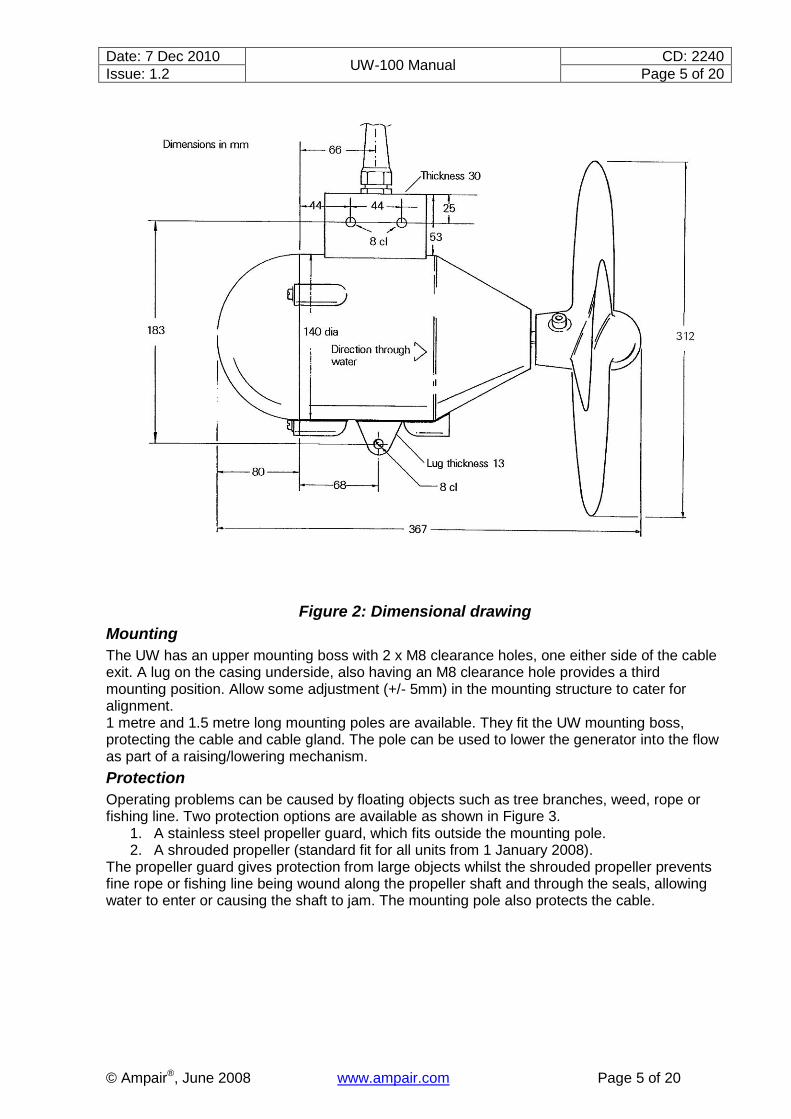
Figure 2: Dimensional drawing
Mounting
The UW has an upper mounting boss with 2 x M8 clearance holes, one either side of the cable exit. A lug on the casing underside, also having an M8 clearance hole provides a third mounting position. Allow some adjustment (+/- 5mm) in the mounting structure to cater for alignment. 1 metre and 1.5 metre long mounting poles are available. They fit the UW mounting boss, protecting the cable and cable gland. The pole can be used to lower the generator into the flow as part of a raising/lowering mechanism.
Protection
Operating problems can be caused by floating objects such as tree branches, weed, rope or fishing line. Two protection options are available as shown in Figure 3.
1. A stainless steel propeller guard, which fits outside the mounting pole. 2. A shrouded propeller (standard fit for all units from 1 January 2008).
The propeller guard gives protection from large objects whilst the shrouded propeller prevents fine rope or fishing line being wound along the propeller shaft and through the seals, allowing water to enter or causing the shaft to jam. The mounting pole also protects the cable.

Date: 7 Dec 2010 UW-100 Manual
CD: 2240
Issue: 1.2 Page 6 of 20
© Ampair®, June 2008 www.ampair.com Page 6 of 20
Figure 3: Protection options
BOATS: Use stainless steel for fabrications (preferably 316 grade) and fasteners (A4 grade) in marine applications. Be sure to separate dissimilar metals with plastic bushing and consider rubber anti-vibration mounts between structure and generator. REMOTE HOMES: Fabrications can be made of steel. Side plates or angle brackets can be made to suspend the UW from an overhead beam or a sliding pole arrangement. HIGH SPEED FLOW: Very fast flowing water requires a special low RPM propeller with fine blades. Care must be taken to protect the blades from damage. WATERSPEED: Accurate water speed data is not normally available. With care speed can be estimated by timing a float along a measured distance, taking seasonal variations into account. The resultant flow range in metres/sec or knots will yield the UW output charge.
Flow rates can be calculated for discharges of known volume flowing in pipes or channels. Convert UK Gallons to cubic ft. (x 0.16) or litres (x 4.55)
(Note. 1 US Gallon = 0.83 UK Gallons) Calculate pipe/channel cross-section area in square ft. or square cm.
Flow rate is calculated from: cubic ft./sec divided by area in square ft. to equal flow in ft/sec. or, 10x litres/sec divided by area in square cm. to equal flow in m/sec.
UW outputs can be read from the curves on the performance graph: 1 ft./sec. = 0.305 m/sec 1m/sec = 1.94 knots

Date: 7 Dec 2010 UW-100 Manual
CD: 2240
Issue: 1.2 Page 7 of 20
© Ampair®, June 2008 www.ampair.com Page 7 of 20
Electrical installation
4m of 4-core cable is fitted to the UW. Tinned copper multi- stranded wire of 1.5 square mm area is used for each core, (16AWG) Number and previous colour codes for wiring.
Generator output phase 1 1 (green) and 2 (brown) to rectifier 1
Generator output phase 2 3 (black) and 4 (blue) to rectifier 2
Rectifier outputs parallel red = positive
black = negative
CAUTION: The generator must never be connected to a system without its rectifiers in circuit, as this risks discharging the battery to which it is connected. When wiring the unit the following points should be observed:
a. The UW is supplied with cable of 1.5 sq. mm conductors. This size is adequate for wiring the UW to the battery, provided the cable run does not exceed 10 metres. For longer runs, refer to table. It is preferable to locate the rectifiers (and regulator if fitted) at the battery site. Four-core cable can be used for interconnections. Each AC phase carries only half the output current giving twice the cable run of a two wire DC system for the same power loss. Two twin core cables can be used if more readily available, allocating one cable to each phase to assist future maintenance. Cable faults may well short out the generator, but the battery is safe, being isolated by the reverse current blocking of the rectifiers.
CABLE LENGTHS IN METRES FOR 10% MAXIMUM POWER LOSS WHEN CONNECTING THE UW TO A BATTERY (1m = 3.28 ft.)
Cable length Cable cross section
2-core DC (metres) 4-core DC (metres) Metric (mm2) Nearest AWG
6 12 1.5 16
10 20 2.5 14
16 32 4.0 12
25 50 6.0 10
40 80 10.0 8
64 128 16.0 6
100 200 25.0 4
b. Any connector must have four contacts rated at 5 amps minimum and should be fitted
with watertight caps when disconnected. c. Any connectors in the DC line should have the pins on the wire from the alternator and
the sockets on the wiring to the battery. d. The rectifier unit should be mounted with the heat-sink fins vertical since it will run
warm. e. It is vital to observe correct polarity throughout since damage can result from wiring
errors. f. We recommend a 0-10A (0-5A) ammeter be fitted in the line to the 12v (24v) battery to
allow monitoring of the output. g. A fuse, rated at 10A for 12v or 5A for 24v, should be placed next to the battery
connection. This will protect the cable in the event of a fault or damage in the generator circuits.
h. It is important that the system is connected in such a way that the generator cannot feed any electrical load without the battery being connected. The generator output should therefore go to the battery side of any isolator switch. Failure to observe this point could place over-voltage on the system and damage sensitive electronic equipment.
NOTE: There is no leakage from the battery to the UW generator when the propeller is not turning since the rectifiers prevent reverse current flow.

Date: 7 Dec 2010 UW-100 Manual
CD: 2240
Issue: 1.2 Page 8 of 20
© Ampair®, June 2008 www.ampair.com Page 8 of 20
CAUTION: When disconnecting the alternator, be aware that if it is spinning, the output voltage, in the absence of a battery, will rise. This can give a mild electric shock to anyone handling the connections.
Electrical fault finding
NOTE. By far the most common cause of reduced output is corroded wiring between UW and battery. Before suspecting the machine, check any screw terminal or crimp connections and all cable runs to the battery.
POSSIBLE FAULTS TO CONSIDER IF REDUCED OUTPUT IS SUSPECTED:
a) Poor wiring connections. Inspect all the screw terminals in the circuit for signs of fatigue or corrosion.
b) Faulty rectifiers. The rectifiers should last the life of the machine. The most likely cause for their demise is accidental reverse polarity connection to the battery. If this is suspected the rectifier diode bridges must be checked. A simple method of checking the machines output is to disconnect it from the battery and short together its output leads whilst turning the shaft by hand. A marked increase in resistance to turning should be felt as the shorting occurs.
DIODE TEST:
This test will show if the rectifier diodes are either open or short circuit. If your multi-meter has a diode check feature, select this (if not select the highest resistance range). Connect the meter leads to the DC output and note the reading. Now reverse the connections.
METER LEAD POSITION MULTIMETER SETTING CONCLUSION
DIODE TEST OHMS x 100
RED meter lead to positive No reading or Many Megohms* OK
Reading or Low resistance Failed
BLACK meter lead to positive 1.2V (two diode drops)
or Markedly less* OK
No reading or High resistance Failed
*This test is not as conclusive as the diode test method, however, provided the first reading is a very high resistance and the second reading far lower, then the test is valid. Actual values will depend on the voltage supplied by the particular meter for its resistance ranges and some meters cannot check 2 diodes in series.
c) Faulty stator. Check AC input to rectifiers or check for coil continuity and isolation from
the case. The resistance should be less than two ohms at 12v (approx. 8 ohms for 24V units).
NOTE. Do not attempt to modify a 12V machine to 24V. Whilst at first sight this may appear possible by connecting the outputs of the stators in series, greatly reduced output will be encountered since they are not in phase. A 24V machine with 24V windings is available.
OPERATION Once the UW has been installed and commissioned, the unit may be lowered into the operating position at any time the flow is over 2 knots or 1 m/sec. (below this speed little output is obtained). CAUTION. On a sailboat, avoid sailing through coral or weed with the UW lowered.

Date: 7 Dec 2010 UW-100 Manual
CD: 2240
Issue: 1.2 Page 9 of 20
© Ampair®, June 2008 www.ampair.com Page 9 of 20
PERFORMANCE
Figure 4: Performance curves
Power production
Mounting forces
Propellor speed

Date: 7 Dec 2010 UW-100 Manual
CD: 2240
Issue: 1.2 Page 10 of 20
© Ampair®, June 2008 www.ampair.com Page 10 of 20
CHARGE CONTROL REGULATOR AMPAIR manufactures 3 Charge Control Regulators for protecting lead acid batteries from overcharge. They are not “shunt” type regulators, which dissipate excess charge as heat, but an electronic power switch, which disconnects the generator from the battery at the regulation voltage. Regulators S1B & S3B have a single 100-watt input (Ampair, Aquair or UW) and 2 level sensing. The lower voltage (Lo) connection regulates at 0.4 Volts below the high (Hi) connection for 12V systems (0.8V for 24V systems). “Hi‟ connection is appropriate for liquid electrolyte batteries and/or live aboard situations. „Lo” connection for gel batteries and/or infrequent use. The battery voltage is sensed at the regulator output connection, therefore install the regulator as near the battery as practicable and keep the connecting cables short. Regulator type S1B has one output battery connection. Regulator S3B has three output connections to serve up to three battery banks with a common negative. The third regulator D1B has two 100 watt inputs (any two from Ampair, Aquair, UW or solar panels), supplying a single battery bank at a fixed regulation voltage. All regulators feature the same multi-stage regulation programme which has regulation voltages of Lo = 13.6V. Hi = 14.0V for l2V systems (27.2V & 28.0V for 24V systems). Charging is continuous until the Lo or Hi voltage is reached, depending on the battery output used. The generator is now disconnected from the battery. Off-charge, the battery voltage will fall. At a voltage of 0.5V below the regulation voltage a 30-second time delay is activated. This delay prevents the regulator from oscillation (hunting) when charging batteries under load. After 30 seconds has elapsed, the generator-to-battery connection is remade and charging continues to the regulation cut-out voltage. A cycle counter counts the charge/disconnect cycles and at the tenth cycle increases the regulation voltage for one cycle only by 0.4 volt to Lo 14.OV or Hi 14.4V for 12V systems (0.8V for 24V systems Lo = 28.OV, Hi = 28.8V). This provides an equalisation charge for the battery. Subsequent cycles return to the lower settings until a further 9 cycles are completed. Ammeter: We recommend fitting an ammeter to monitor charging. Use 10A for 12v, 5A for 24v. Fit an ammeter with a linear scale (moving coil type) or low outputs will be indiscernible. Fuses: Battery protection fuses should be fitted. Use l0A in 12v system, 5Amp for 24v. Wiring: Use suitably insulated cable of 1.5 sq. mm (16 A.W.G.) between regulator and battery in single source systems; 2.5 sq. mm (14 A.W.G.) for dual source. For input wiring to the regulator see appropriate generator wiring section. The use of screened cables is recommended if the cables run close to equipment radiating strong electrical fields e.g. radio transmitters or aerials.
Installation of charge control regulator
Make sure the generator is not operating whilst connecting to the regulator. Connecting with live wires can damage the electronic regulation circuit. At initial start-up, allow a time of 1-2 minutes for circuit timing functions to become active. Protecting the system: Fuse warning - never omit fuses, simple in-line fuse carriers may be used, they protect your system from excessive battery currents in the event of a serious electrical fault. If they keep blowing, find out why. Fuses = l0A for 12V systems; 5A for 24V systems.

Date: 7 Dec 2010 UW-100 Manual
CD: 2240
Issue: 1.2 Page 11 of 20
© Ampair®, June 2008 www.ampair.com Page 11 of 20
The regulators are internally protected by SAE fuses, which are not substitutes for battery protection fuses. The fuses must be next to the battery terminals since, in the event of a fault, the batteries would source the fault current. Check and double-check polarities before making connections, insert the fuses in the fuse carriers last of all. Corrosion: This is the enemy of all electrical connections, especially in marine environments. Site regulators in a weather proof location, as dry as possible, and splash proof. Inspect all terminations and connections for signs of corrosion. Rectify by cleaning, remaking etc. Use tinned copper wire for extension leads to prevent corrosion spreading inside cable insulation. Operating problems: A digital multi-meter is useful for checking operational faults, if no permanent monitoring instruments are used. Battery voltage levels and those of the charging source can be read directly. Charging current readings will require the multi-meter to be installed in line. In this way currents into and out of the regulator can be observed. Do not remove battery connections since regulator operation depends on a very small supply current. If the regulator is suspect then it can be temporarily bypassed by connecting the source positive direct to a battery positive. The negative connections are common and do not need disturbing unless regulator replacement is necessary. Use the multi-meter continuity range to confirm all cable runs are low resistance. Operation: When installed, the generator and regulator will run and maintain the batteries automatically. The unit may be run in conjunction with any other charge-source with no known interactive problems. Regular battery inspection and topping up must still be carried out to obtain maximum battery life. Faulty regulator: Each regulator is individually tested and a chart recording kept of its operation. Each regulator has a unique serial number and a test date. Please provide these with any queries. If the regulator is suspect, then it can be temporarily bypassed i.e. connect the UW rectifiers directly to the battery terminals observing correct polarity. If this reinstates correct charging, then the regulator must be serviced or replaced. Regulators draw a small current (typically 1mA at 12V) from the battery to activate the sense and control circuits. Without this connection the regulator will be inoperative.

Date: 7 Dec 2010 UW-100 Manual
CD: 2240
Issue: 1.2 Page 12 of 20
© Ampair®, June 2008 www.ampair.com Page 12 of 20
Figure 5: Charge control regulators

Date: 7 Dec 2010 UW-100 Manual
CD: 2240
Issue: 1.2 Page 13 of 20
© Ampair®, June 2008 www.ampair.com Page 13 of 20
UW MAINTENANCE Preventative maintenance
Practical problems, which will cause faults if not corrected are: a) Abrasion or stress of output cable resulting in loss or part loss of output due to cable
breakage. b) Loose propeller fasteners. This will eventually cause shaft wear requiring factory
replacement! c) Fouling of propeller by rope or fishing line small enough to be drawn into the generator
through the seals causing a leakage path. A shrouded propeller is recommended to prevent this.
d) The shaft seals should periodically be changed to prevent worn seals leaking. Periods of 2 - 3 years, dependent on use, can elapse between servicing.
e) The paint on the housing and propeller should be examined and any damage re-painted, especially if the water has a salt content.
Propeller removal
The use of adhesive on the cap screw during installation may make it difficult to remove. An extension tube on the key may be necessary to free this screw. To remove the propeller from the shaft, gently tap the boss to ease it off. Do not hammer the blades. If the prop is stuck on the shaft, drill and tap an M10 hole through the prop boss centre on the shaft axis and, using a suitable length of bolt, draw the prop off the shaft. In severe cases the threads may strip and the propeller will have to be cut away with a hacksaw and replaced.
Seal change
In all units manufactured from September 1996 onwards 3 seals are arranged in-line, on the alternator shaft, with the seal faces outwards. Both front and middle seals can be changed without stripping the machine.
a) Remove slit cover washer from groove in housing. A sharp edge will help to lift the cover away from the groove.
b) Carefully lever out the front seal with the blade of a screwdriver, taking care not to damage the casting or shaft.
c) To remove the middle seal, drill two small diametrically opposing holes through the middle seal taking care not to over-travel to the inner seal. Improvise a wire coat hanger puller.
d) Thoroughly clean the housing of all traces of old grease and swarf from the drill. e) Part-fill the gaps between the new seals with water repelling grease. f) Identify outer seal with stainless steel spring and separate from remaining seals with
steel springs. g) Slide the seals into place. If necessary, use a thin wire laid axially along the shaft to
allow air to escape from the housing through the seal as it is pressed into place. Remove the wire. The middle seal may need tapping home, press on the outer seal rim only.
h) Refit seal cover washer by overlapping the ends and springing into groove. NOTE: All UW generators manufactured prior to Sept. 1996 have outer seal facing inwards to protect steel spring.
UW disassembly
Before commencing work, prepare a stand for the UW. This can be a simple block of wood with a hole drilled to take the alternator shaft such that the alternator rests vertically with hemisphere uppermost. Stand the block and generator in a tray to catch any fluid spill. Make a cable feed-through seal extractor tool as follows: Obtain a piece of metal tube 14 -16mm diameter and at least 100mm long with a bore large enough to take the cable. Cut and file one end to produce two prongs of size 3 x 3mm, 180 degrees apart.
a) Undo the cable gland tail, extract the clamp ring and rubber seal and slide off the cable.
Date: 7 Dec 2010 UW-100 Manual
CD: 2240
Issue: 1.2 Page 14 of 20
© Ampair®, June 2008 www.ampair.com Page 14 of 20
b) Undo the gland body. This has been fitted using polyurethane sealant (Sika-Flex 221) on the thread and will be stiff to turn. Pick out any sealant residue from the cable hole thread.
c) Unscrew the three fasteners and remove the hemisphere and „0” ring. A small residue of fluid will be present.
d) Undo filler screw and invert the machine to drain fluid into suitable container for careful disposal. Any water present will be emulsified within the oil (very little oil will emerge until the next step).
e) Take the extractor tool described above and thread over the cable, prongs first. Insert the tool into the cable hole, locating the prongs in the threaded sleeve. Make sure the machine is over the oil container and undo the sleeve 4 to 5 turns and gently pull the cable. This will allow air into the body and allow the oil to fully drain.
f) Tap the shaft through the body with a hide mallet. Do not damage the shaft face by using a steel hammer. When the shaft face is flush with the body nose, use a suitable drift to complete the withdrawal of the back-plate and shaft assembly.
g) Thoroughly clean the shaft and rotors, checking that the two rotors are arranged on the shaft with their magnetic poles 30 degrees apart. NOTE: Rotor removal requires a high tonnage press. We suggest the shaft assembly be returned to the factory if the rotors or shaft are damaged. Do not disturb cable or stator wiring unless replacement is necessary.
h) Inspect both stator windings, especially all soldered joints between the coils. Corrosion can only be the result of water ingress. Bad corrosion will cause irreparable damage.
i) Inside the body, locate four wire tails: 1 (formerly green), 2 (formerly brown), 3 (formerly black) & 4 (formerly blue). Gently manoeuvre them to allow their connections to the stator output wires to be dc-sleeved and dc-soldered.
j) Undo the threaded sleeve. Withdraw cable, sleeve, feed-through seal and “0” ring. Inspect the connections on the feed-through seal.
k) Press or drift the front bearing out into the body. NOTE: The stators are retained in the body using Loctite 648 adhesive. If the unit cannot be returned to Ampair, and stator replacement is necessary, proceed as follows:
Removal of stators
Place a block of wood on a concrete floor. Holding the generator body nose up, in both hands, bring it down sharply on the block to strike it squarely. Proceed carefully, collecting two stators and taking particular care not to distort the body casting. In case of difficulty it may be necessary to bake the UW housing in an oven to break the adhesive bond.
Reassembly
All components to be reassembled must be clean and free of grease. Adhesive bonding is used throughout. We specify Loctite products, but equivalents are acceptable. Activators to suit these adhesives should be used if available. The three shaft seals should always be replaced after servicing the machine. Use Loctite 641 between bearing and housing
Loctite 648 with activator T for the stators Loctite 641 between shaft & bearing
a) Insert inner seal flat side inward and press tight to the front bearing circlip. It may need
tapping home, press on the outer rim only. b) Prepare the body to accept the stators by removing old adhesive residue. Remove any
traces of oil using solvent on a cloth c) Fit the front stator, lowering it into the body as far as it will go making sure the output
wires are adjacent to the cable exit hole. Leave the body nose down while the adhesive cures.
d) With a new „0” ring on the feed-through seal, gently push the tails through the cable hole until the seal is fully seated. Screw the threaded sleeve into place and tighten fully.

Date: 7 Dec 2010 UW-100 Manual
CD: 2240
Issue: 1.2 Page 15 of 20
© Ampair®, June 2008 www.ampair.com Page 15 of 20
e) Fit the gland body using a little polyurethane sealant on the thread. f) Fit its rubber seal, clamp ring and tail, tighten cautiously. g) Solder and sleeve the connections from tail 1 (formerly green) and tail 2 (formerly
brown) to the front stator output wires. The polarity is unimportant as the rectification is external.
h) Insert the stator spacer. i) Fit the rear stator, lowering it onto the spacer, making sure the output wires are aligned
with the cable hole and in line with those on the front stator. Allow the adhesive to cure. Solder and sleeve the connections to tail 3 (formerly black) and tail 4 (formerly blue).
j) Refit the back-plate with a new “0” ring and, if necessary, the bearing. Use Loctite 641 for bearing to plate and bearing to shaft bonding.
k) Push shaft assembly back into the body having first run a ring of adhesive around shaft at start of bearing position. A smear of hydraulic oil on the plate seal will assist.
l) Return alternator to its stand and immediately fill with approx. 1 litre of mineral oil, viscosity 1500 centistokes (I.S.O. 15). The use of a small funnel is advisable. UW generators manufactured from the end of 2005 onwards, are filled with a „food grade‟ liquid paraffin of the same viscosity.
m) Wind some PTFE tape around the threads of the filler screw. Squeeze the rubber reservoir to expel air until filling is complete. At this point insert and tighten the screw whilst still squeezing the reservoir. The idea is to leave the reservoir approx. half full at room temp. Make sure the plate is fully pressed in before finally tightening the filler screw.
n) Leave oil spillage inside rear housing for added corrosion protection. Replace “0” ring beneath hemisphere and screw it down evenly until it bottoms. This leaves a uniform gap between the hemisphere and body of 1.0 - 1.5mm.
o) Invert alternator and fit new middle and front seals as above adding a small quantity of hydraulic fluid to the inner seal and a quantity of PTFE grease to the middle seal. Fit seal cover washer into groove of body. Overlap ends of washer to spring into place.
Testing
When the machine is bench tested, the output should typically be as follows for 12V units (for 24V, double the volts; half the amps):
RPM 250 500 750 1000 1250 1500
No load Volts 9 17 25 32 40 47
Amps per phase 0.5 2.2 3.4 4.1 4.3 4.6
Notes: The no load volts readings are taken with a digital voltmeter set to AC volts, with no rectification in circuit. The Amps per phase readings are taken with an AC ammeter before the bridge rectifier for that phase. The charge from both phases is not equal to the sum of the two phases since there is a phase difference between them.

Date: 7 Dec 2010 UW-100 Manual
CD: 2240
Issue: 1.2 Page 16 of 20
© Ampair®, June 2008 www.ampair.com Page 16 of 20
COMPONENT PARTS DRAWING
Figure 6: Component parts drawing

Date: 7 Dec 2010 UW-100 Manual
CD: 2240
Issue: 1.2 Page 17 of 20
© Ampair®, June 2008 www.ampair.com Page 17 of 20
Key to component parts drawing
Key Description Drg No Accounting Code
1. Body casting CSTM 0013 .AB W01 042
2. Stator spacer NMETL 0013 .NML W01 013
3. Stator winding ASMB 0046 .AB W01 044
4. Cable gland CBLSR-M20 .CBL SR M20
5. Output cable, 4 metres 4 core 1.5 sq. mm cores - .WRP 4 x 01.5T
6. Permanent magnet rotor in ASMB 0047 .AB A00 016
7. Front bearing, 17 x 40 x 12mm Type 6203 BRNG 6203 .BRG 6203
8. Internal circlip, 40 x 1.75mm CIRCI 40-1 .CRCI 40-1
9. Shaft seal, rubber plain lip, 17 x 40 x 7mm (3 required) & cover washer
2 x SEAL SC 1740-7 1 x SEAL SF 1740-7 1 x NMETL 021
2 x .SEA SC1740-7R21 1x .SEA 1740-7VR21 1 x .NML W01 021
10. Shaft, stainless steel, grade 316 METL 0030 .MTL W01 030
11. Propeller bush stainless steel METL 0061 .MTL W01 061
12. Propeller fastener M8 x 30mm grade A4 stainless steel cap screw complete with M8 shake-proof washer
SCRM 8x30 01SS WSHR 8-5
.SCR M08 x 30-01
.WSR 08-5
13. 3-blade propeller casting ASMB 0049 .AB W01 046
14. Base mounting lug, M8 clearance hole n/a n/a
15. Rear bearing, 15 x 35 x 11mm Type 6202 BRNG 6202 .BRG 6202
16. “0” ring retaining plate MTL 0090 .CM W01 012
17. “0” ring, metric size 351 ORG 1200 x 533 .ORG 1200 x 533
18. Oil reservoir, Nitrile (synthetic rubber) moulding ASMB 0043 .NML W01 017
19. Plastic reservoir attachment CBLG-PG11 .NML W01 020
20. Oil filler screw, M8 x 12mm SCRM8 x 12-05SS .SCR M08 x 12-06
21. Water seal “0” ring, metric size 351 ORG 1200 x 533 .ORG 1200 x 533
22. Helicoil, M6 x 15mm stainless steel (3 required) HLCM 6x25L .GEN W01 HLCM6x25F
23. Hemisphere casting CSTM 0015 .AB W01 043
24. Hemisphere Fastener, M6 x 25mm stainless steel grade A4 & Shake-proof washer (3 of each required)
3 x SCRM 6x25 01SS 3 x WSHR 6-5
3 x .SCR M06x25 3 x .WSR 06-5
Cable seal components, not shown:
a) Threaded sleeve NMETL 009 .NML W01 009
b) Feed-through seal body ASMB 0053 .NML W01 010
c) Feed-through seal “0” ring size 614 ORGI 191x262 .ORG BS61 4N
WARRANTY Please see Ampair terms and conditions, available on request. Please keep your invoice as proof of purchase.
SERVICING & REPAIRS UW‟s should be returned to:
Ampair Energy Ltd Unit 2, Milborne Business Centre, Blandford Hill Milborne St Andrew, Blandford Forum, Dorset DT11 0HZ United Kingdom Tel +44 (0) 1258 837 266 Fax +44 (0) 1258 837 496 Email: [email protected] Web: www.ampair.com
Ampair reserves the right to change specifications, without prior notice, in the interest of product development.

Date: 7 Dec 2010 UW-100 Manual
CD: 2240
Issue: 1.2 Page 18 of 20
© Ampair®, June 2008 www.ampair.com Page 18 of 20
Date: 7 Dec 2010 UW-100 Manual
CD: 2240
Issue: 1.2 Page 19 of 20
© Ampair®, June 2008 www.ampair.com Page 19 of 20

Date: 7 Dec 2010 UW-100 Manual
CD: 2240
Issue: 1.2 Page 20 of 20
© Ampair®, June 2008 www.ampair.com Page 20 of 20