zeversolar service line - rpc.com.au
TRANSCRIPT

2015/07/10
Zeversolar Service Line
China (incl. Hongkong, Macau)Jiangsu Zeversolar New Energy Co., Ltd.
Tel.: +86 512 6937 0998-8866
E-mail: [email protected]
Add.: Building 9, No.198 Xiangyang Road, Suzhou 215011, China
AustraliaZeversolar Australia
Tel.: +61(0)1300101883
E-mail: [email protected]
Add.: Suite 2.23 Level 2, 838 Collins Street, Melbourne, Docklands Vic 3008, Australia
Europe RegionZeversolar GmbH
Tel.: +49(0) 2102 420 944
E-mail: [email protected]
Add.: Luxemburger Straße 59, 50674 Köln, Germany
United Kingdom:
Tel.: +44 (0) 800 731 0899
E-mail: [email protected]
Rest of the world
E-mail: [email protected]

Installation and Operating Instructions 1
Table of Contents
1 About this manual............................................................................................................. 5
1.1 Validity ........................................................................................................................ 5
1.2 Target group .............................................................................................................. 5
1.3 Symbols used in this manual .................................................................................... 6
2 Safety ............................................................................................................................... 7
2.1 Intended use............................................................................................................... 7
2.2 Safety standards ...................................................................................................... 7
2.3 Important safety information .................................................................................. 8
2.4 Symbols on the type label ..................................................................................... 10
2.5 Basic safety protection ........................................................................................... 11
3 Unpacking ........................................................................................................................12
3.1 Scope of delivery .....................................................................................................12
3.2 Check for transport damage...................................................................................12
4 Mounting ..........................................................................................................................13
4.1 Ambient conditions...................................................................................................13
4.2 Selecting the mounting location .............................................................................15
4.3 Mounting the inverter with the wall bracket ........................................................ 16
5 Electrical connection ..................................................................................................... 18
5.1 Safety ....................................................................................................................... 18
5.2 System layout of units without integrated DC-switch ......................................... 19
5.3 Overview of the connection area...........................................................................20
5.4 AC Connection ..........................................................................................................21 5.4.1 Conditions for the AC connection ......................................................................................21

2 Installation and Operating Instructions
5.4.2 Grid connection ....................................................................................................................... 22 5.4.3 Second protective grounding connection ....................................................................24 5.4.4 Residual current protection .............................................................................................. 25 5.4.5 Overvoltage category ......................................................................................................... 25 5.4.6 AC circuit breaker .................................................................................................................. 26
5.5 DC Connection ......................................................................................................... 27 5.5.1 Requirements for the DC connection ............................................................................. 27 5.5.2 Assembling the DC Connectors ...................................................................................... 28 5.5.3 Disassembling the DC Connectors ................................................................................ 30 5.5.4 Connecting the PV Array .....................................................................................................31
6 Communication .............................................................................................................. 33
6.1 Monitoring system .................................................................................................. 33
6.2 Updating the firmware via USB ............................................................................. 37
6.3 Communication with a third party monitoring equipment ................................... 37
7 Commissioning ...............................................................................................................38
7.1 Electrical checks ......................................................................................................38
7.2 Mechanical checks .................................................................................................. 39
7.3 Start-up ................................................................................................................... 39
8 Disconnecting the inverter from voltage sources ...................................................... 40
9 Operating .........................................................................................................................41
9.1 Overview of the control panel.................................................................................41
9.2 LED indicators ......................................................................................................... 42
9.3 Display messages................................................................................................... 43
9.4 Display .................................................................................................................... 45 9.4.1 Overview of menu structure ............................................................................................. 45 9.4.2 Initial page ................................................................................................................................. 46 9.4.3 Unlock page ............................................................................................................................. 46

Installation and Operating Instructions 3
9.4.4 Home page ............................................................................................................................... 46 9.4.5 Operation information .......................................................................................................... 47 9.4.6 Main menu ................................................................................................................................ 48 9.4.7 Statistics .................................................................................................................................... 48 9.4.8 Event log ................................................................................................................................... 49 9.4.9 Date&Time setting ................................................................................................................ 49 9.4.10 Language setting ................................................................................................................. 50 9.4.11 Contrast setting ..................................................................................................................... 50 9.4.12 Safety regulations setting ................................................................................................ 51 9.4.13 Overload setting ................................................................................................................... 52 9.4.14 Active power control ......................................................................................................... 52 9.4.15 Reactive power control..................................................................................................... 53 9.4.16 PV Mode setting ................................................................................................................... 54 9.4.17 EEG setting .............................................................................................................................. 55 9.4.18 Communication setting ..................................................................................................... 56 9.4.19 Device information .............................................................................................................. 56 9.4.20 Clear the history data ........................................................................................................57
10 Technical data ...............................................................................................................58
10.1 DC input data ..........................................................................................................58
10.2 AC output data ......................................................................................................58
10.3 General data ..........................................................................................................59
10.4 Safety regulations ............................................................................................... 60
10.5 Efficiency ............................................................................................................... 61 10.5.1 Efficiency curve TLC8000 ................................................................................................ 61 10.5.2 Efficiency curve TLC10000 ............................................................................................ 62
10.6 Power reduction.................................................................................................... 63
11 Troubleshooting ............................................................................................................64
12 Maintenance ..................................................................................................................66
12.1 Cleaning the contacts of the DC-switch................................................................66

4 Installation and Operating Instructions
12.2 Cleaning the heat sink ...........................................................................................66
13 Recycling and disposal ................................................................................................. 67
14 Warranty ....................................................................................................................... 67
15 Contact ......................................................................................................................... 68

Installation and Operating Instructions 5
1 About this manual
General Notes Evershine is a transformerless solar inverter with two MPP trackers.It converts the
direct current (DC) from aphoto-voltaic (PV) generator to grid-compliant alternating
current (AC) and feeds it into the grid.
1.1 Validity
This manual describes the mounting, installation, commissioning and maintenance of
the following Zeversolar inverters:
EvershineTLC8000, EvershineTLC10000.
Observe all documentation that accompanies the inverter. Keep them in a convenient
place and available at all times.
1.2 Target group
This manual is for qualified electricians only who must perform the tasks exactly as
described.
All persons installing inverters must be trained and experiencedin general safety
which must be observed when working on electrical equipment. Installation
personnel should also befamiliar with local requirements, rules and regulations.

6 Installation and Operating Instructions
1.3 Symbols used in this manual
The following safety precautions and general information are used in this manual:
DANGER indicates a hazardous situation which, if not avoided, will result in death or serious
injury.
WARNING indicates a hazardous situation which, if not avoided, can result in death or
serious injury.
CAUTION indicates a hazardous situation which, if not avoided, can result in minor or
moderate injury.
NOTICE indicates a situation which, if not avoided, can result in propertydamage.
INFORMATION provides tips which are valuable for the optimal installation and operation of
the inverter.

Installation and Operating Instructions 7
2 Safety
2.1 Intended use
1. Evershine converts the direct current from a PV generator into grid-compliant
alternating current.
2. Evershine is suitable for indoor and outdoor use.
3. Evershine must only be operated with PV arrays (PV modules and cabling) of
protection class II, in accordance with IEC 61730, application class A.
Do not connect any sources of energy other than PV modules to the Evershine.
4. PV modules with a high capacitance to earth may only be used if their coupling
capacity does not exceed 1.0μF.
5. When the PV modules are exposed to light, a DC voltage is supplied to this
equipment.
6. When designing the PV installation, ensure that the values comply with the
permitted operating range of all components at all times. The free design
program "Zeverplan" (http://www.zeverplan.com)will assist you.
2.2 Safety standards
Evershine complies with the EU Low Voltage Directive 2006/95/EC and the EMC
Directive 2004/108/EC. Evershine also complies with the requirement for safety and
EMC in Australia and New Zealand market.
The inverters are labeled with the CE and RCM mark and fulfill the requirements
specified in the specific standards.
For more information about certificates in other countries and regions, please visit
website (Http://www.zeversolar.com).

8 Installation and Operating Instructions
2.3 Important safety information
Possible damage to health as a result of the effects of electromagnetic
radiation !
• Please maintain a distance of at least 20cm from the inverter when it is
inoperation.
Risk of injury due to hot heat sink !
• The heat sink may get hot during operation. Do not touch!
Risk of injury due to electric shock and fire caused by high leakage current !
• The inverter must be reliably grounded in order to protect property and
personal safety.
• All work on the inverter must only be carried out by qualified personnel who
have read and fully understood all safety information contained in this manual.
• Children must be supervised to ensure that they do not play with this device.

Installation and Operating Instructions 9
Damage to the seal of the cover in sub-zero conditions !
• If you open the cover in sub-zero condition, the sealing of the cover can be
damaged.This can lead moisture entering the inverter.
• Do not open the inverter at ambient temperatures lower than -5℃.
• If a layer of ice has formed on the seal of the cover in sub-zero comditions,
remove it prior to opening the inverter (e.g. by melting the ice with warm air).
Observe the applicable safety regulation.
Grounding the PV array !
• Comply with local regulations for grounding the PV array. We suggest the
frames of PV modules must be reliably grounded.
• Do not ground any of the terminals of the strings.
10 Installation and Operating Instructions
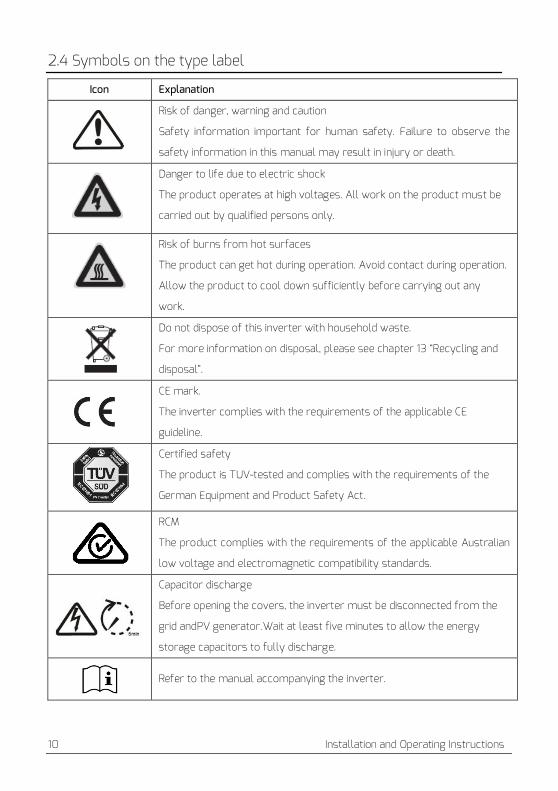
2.4 Symbols on the type label
Icon Explanation
Risk of danger, warning and caution
Safety information important for human safety. Failure to observe the
safety information in this manual may result in injury or death.
Danger to life due to electric shock
The product operates at high voltages. All work on the product must be
carried out by qualified persons only.
Risk of burns from hot surfaces
The product can get hot during operation. Avoid contact during operation.
Allow the product to cool down sufficiently before carrying out any
work.
Do not dispose of this inverter with household waste.
For more information on disposal, please see chapter 13 “Recycling and
disposal”.
CE mark.
The inverter complies with the requirements of the applicable CE
guideline.
Certified safety
The product is TUV-tested and complies with the requirements of the
German Equipment and Product Safety Act.
RCM
The product complies with the requirements of the applicable Australian
low voltage and electromagnetic compatibility standards.
Capacitor discharge
Before opening the covers, the inverter must be disconnected from the
grid andPV generator.Wait at least five minutes to allow the energy
storage capacitors to fully discharge.
Refer to the manual accompanying the inverter.

Installation and Operating Instructions 11
2.5 Basic safety protection
We provide the following safety protection:
1. Overvoltage, undervoltage protection.
2. Overfrequency, underfrequency protection.
3. Overtemperature monitoring.
4. Residual current monitoring.
5. Isolation fault detection.
6. Anti islanding protection.
7. DC feed-in monitoring.

12 Installation and Operating Instructions
3 Unpacking
3.1 Scope of delivery
Object Description Quantity
A Inverter 1
B Wall bracket 1
C
Mounting accessory kit: large plain washers (2×) M5×12 pan head screw (2×) wall anchors and bolts(4×), terminal lug (1×), ground washer (1×)
1
D DC connector 3
E AC connection plug 1
F RJ45 plug 2
G Documentation 1
A B C D
E F G
Please carefully check all of the components in the carton. If anything is missing,
contact your dealer at once.
3.2 Check for transport damage
Thoroughly inspect the packaging upon delivery.If you detect any damage to the
packaging which indicates the inverter may have been damaged, inform the
responsible shipping company immediately. We will be glad to assist you if required.
Installation and Operating Instructions 13
4 Mounting
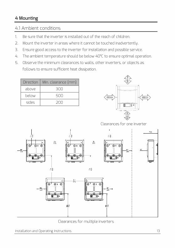
4.1 Ambient conditions
1. Be sure that the inverter is installed out of the reach of children.
2. Mount the inverter in areas where it cannot be touched inadvertently.
3. Ensure good access to the inverter for installation and possible service.
4. The ambient temperature should be below 40°C to ensure optimal operation.
5. Observe the minimum clearances to walls, other inverters, or objects as
follows to ensure sufficient heat dissipation.
Clearances for one inverter
Clearances for multiple inverters
Direction Min. clearance (mm)
above 300
below 500
sides 200

14 Installation and Operating Instructions
6. In order to avoid power reduction caused by overheating, do not mount the
inverter in a location that allows long-term exposure to direct sunlight.
7. Avoid exposing the inverter to direct sunlight, rain and snow to ensure optimal
operation and extend service life.
8. The mounting method, location and surface must be suitable for the inverter's
weight and dimensions.
9. If mounted in a residential area, we recommend mounting the inverter on a solid
surface. Plasterboard and similar materials are not recommended due to
audible vibrations when in use.
10. Don’t put any objects on the inverter.Do not cover the inverter.

Installation and Operating Instructions 15
4.2 Selecting the mounting location
Danger to life due to fire or explosion!
•Do not mount the inverter on flammable construction materials.
•Do not mount the inverter in areas where flammable materials are stored.
•Do not mount the inverter in areas where there is a risk of explosion.
1. Mount the inverter vertically or tilted backward by max. 15°.
2. Never mount the inverter tilted forward or sideways.
3. Never mount the inverter horizontally.
4. Mount the inverter at eye level to make it easy to operate and to read the
display.
5. The electrical connection area must point downwards.

16 Installation and Operating Instructions
4.3 Mounting the inverter with the wall bracket
Risk of injury when lifting the inverter, or if it is dropped! • The inverter weighs 25 kg.There is risk of injury if the inverter is lifted incorrectly or
dropped while being transported or when attaching it to or removing it from the
wall mounting bracket.
• Transport and lift the inverter carefully.
Mounting procedures:
1. Use the wall bracket as a drilling template
and mark the positions of the drill holes, then
drill 4 holes (Φ10) to a depth about 70mm.
During operation, keep the drill vertical to the
wall, and hold the drill steady to avoid tilted
holes. After cleaning the dust from the holes,
measure their net depth.
2. After drilling holes in the wall, place 4 wall anchors into the holes, then attach
the wall bracket to the wall using the self-tapping bolts delivered with the
inverter.

Installation and Operating Instructions 17
3. Hold the inverter using the handles on the coner, attach the inverter onto the wall
bracket tilted slightly downwards.
4. Check both sides of the inverter to ensure that it is securely in place..
5. Attach the outer fin of the heatsink to both sides of the wall bracket using the M5
screws and washers(screw driver type: T25, torque: 2.5Nm).
If a second protective conductor is required locally, ground the inverter and secure
it so that it cannot be lifted off the wall bracket (see section 5.4.3 “Second
protective grounding connection”, page 24).

18 Installation and Operating Instructions
5 Electrical connection
5.1 Safety
Risk of injury due to electric shock!
• The inverter must be installed only by trained and authorized electricians.
• All electrical installations must be done in accordance with the National Wiring Rules
Standards and Local Code.
Risk of injury due to electric shock!
• The external protective earthing conductor is connected to the inverter’s protective
grounding terminal through the AC connector. Make sure the connection is reliable.
• When connecting, connect the AC connector first to ensure the inverter grounding and then
connect the DC inputs.
• When disconnecting, disconnect the DC inputs first and then disconnect the AC connector.
• Under any circumstances, do not connect the DC inputs when the AC connector is
unplugged.

Installation and Operating Instructions 19
5.2 System layout of units without integrated DC-switch
Local standardsor codes may require that PV systems are fitted with an external
DC-switch on the DC side. The DC-switch must be able to safely disconnect the
open-circuit voltage of the PV array plus a safety reserve of 20%.
Install a DC-switch to each PV array to isolate theDC side of the inverter. We
recommend the following electrical connection:

20 Installation and Operating Instructions
5.3 Overview of the connection area
Object Description
A DC-switch (optional): switch on or off for PV-load
B DC input: plug-in connectors to connect the strings
C RJ45 interface: connect the monitoring device
D USB (DSP) interface: update the DSP firmware
E USB (HMI) interface: update the HMI firmware
F AC output: plug-in connector to connect the grid
Installation and Operating Instructions 21
5.4 AC Connection
Danger to life due to high voltages in the inverter!
Before do the electrical connection, ensure that the AC circuit-breaker is switched off and
cannot be reactivated.
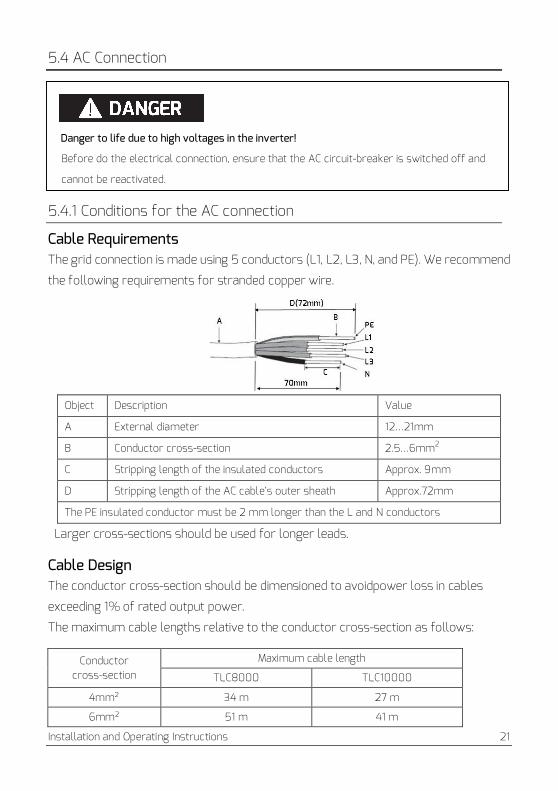
5.4.1 Conditions for the AC connection
Cable Requirements The grid connection is made using 5 conductors (L1, L2, L3, N, and PE). We recommend
the following requirements for stranded copper wire.
Object Description Value
A External diameter 12…21mm
B Conductor cross-section 2.5…6mm2
C Stripping length of the insulated conductors Approx. 9mm
D Stripping length of the AC cable’s outer sheath Approx.72mm
The PE insulated conductor must be 2 mm longer than the L and N conductors
Larger cross-sections should be used for longer leads.
Cable Design The conductor cross-section should be dimensioned to avoidpower loss in cables
exceeding 1% of rated output power.
The maximum cable lengths relative to the conductor cross-section as follows:
Conductor cross-section
Maximum cable length
TLC8000 TLC10000
4mm² 34 m 27 m
6mm² 51 m 41 m

22 Installation and Operating Instructions
The required conductor cross-section depends on the inverter rating, ambient
temperature, routing method, cable type, cable losses, valid installation
requirements of the country of installation, etc.
5.4.2 Grid connection
Overview of the AC connection plug and the plastic fixture
A B C D E F
Object Description
Accessory A Plastic fixture
AC
Connection
Plug
B Socket element
C Adapter
D* Seal ring Thicker seal ring is suitable for cable diameter 12-18mm
Thinner seal ring is suitable for cable diameter 16-21mm
E Fasteningcase
F Swivel nut
*There are two seal rings in the AC connection plug kit, please choose the suitable
one according to different cable external diameter.
Procedure 1. Switch off the AC circuit breaker and secure it reconnection.
2. Guide the swivel nut, the fastening case with sealing ring and the adapter over the
AC cable.
3. Strip the cable’s outer sheath (72mm) and the conductors’ insulation (9mm).

Installation and Operating Instructions 23
4. Insert bared conductors into the cord end terminals and crimp them by using a
crimping tool.
5. Insert the crimped conductors L1, L2, L3, N and PE into the corresponding
terminals and tighten the screw with torque 2.0Nm using an Allen key(AF 2.5).
The inverter can be destroyed due to the wrong wiring!
Please ensure that the phase of the conductors matches the signs of the screw terminals on
the socket element.
6. Assemble the socket element, adapter and swivel nut together. Match the plastic
fixture with the socket element and grip them, then screwthe adapter and swivel
nut as shown below with a torque of 3-4Nm.
7. Insert the AC connect plug into the receptacle with the arrow aimed at the
corresponding slot. Finally rotate the socket element clockwise until it audibly
snaps into place.

24 Installation and Operating Instructions
5.4.3 Second protective grounding connection
If required, the grounding terminal can be used to connect a second protective
conductoror as equipotential bonding.
Procedure
1. Take out the terminal lug, insert the stripped earthing conductor into the terminal
lugand crimp the contact.
2. Align the washer, the terminal lug with protective conductor and the ground
washer on the screw. The teeth of the ground washer must be facing the heat
sink.
3. Insert the screw through the hole located at the side of the heat sink and tighten
it into the wall bracket firmly(screw driver type: T25, torque: 2Nm).
Earthing parts information:
No. Description
1 Heatsink
2 Ground washer Φ5
3 Terminal lug(M5) with protective conductor
4 Large plain washer Φ6
5 M5×12 pan head screw

Installation and Operating Instructions 25
5.4.4 Residual current protection
The inverter is equipped with an all-pole sensitive residual current monitoring
unit(RCMU) with an integrated differential current sensor which fulfills the
requirement of DIN VDE 0100-712 (IEC60364-7-712:2002).
Therefore, an external residual current device (RCD) is not required. If an external
RCD needs to be installed because of local regulations, a RCD type A or type B can be
installed as an additional safety measure.
The all-pole sensitive residual current monitoring unit (RCMU) detects alternating
and direct differential currents. The integrated differential current sensor detects
the current difference between the neutral conductor and the line conductor. If the
current difference increases suddenly, the inverter disconnects from the grid. The
function of the all-pole sensitive residual current monitoring unit(RCMU) has been
tested according to IEC 62109-2.
INFORMATION If an external residual current device (RCD) needs to be used, please refer to the
information below.
Where an external residual current device (RCD) is required in a TT or TN-S system, install a
residualcurrent device which trips at aresidual current of 100mA or higher.
For each connected inverter, a rated residual current of 100mA has to be provided. The rated
residual currentof the RCD must be equal to at least the sum of the rated residual currents of
the connectedinverters.That means that, if, for example, 2 transformerless inverters are
connected, the rated residual current of the RCD must be at least 200mA.
5.4.5 Overvoltage category The inverter can be deployed in grids of installation category III or lower, as defined
under IEC 60664-1. This means that it can be permanently connected at the
grid-connection point in a building. In installations involving long outdoor cable routing,
additional overvoltage-reducing measures must be taken so that the overvoltage
category is reduced from IV to III.

26 Installation and Operating Instructions
5.4.6 AC circuit breaker
Danger to life due to fire! You must safeguard each inverter with an individual AC circuit breaker in order that the
inverter can be disconnected safely.
No consumer load should be applied between AC circuit breaker and the inverter. The
selection of the AC circuit breaker rating depends on the wiring design (wire
cross-section area), cable type, wiring method, ambient temperature, inverter current
rating, etc. Derating of the AC circuit breaker rating may be necessary due to
self-heating or if exposed to heat.
The maximum output current of the inverters can be found in the following table.
Type TLC8000 TLC10000
Max. output current 13.3A 15.1A
Recommended fuse type gL/gG or com-
parable automatic circuit breaker rating 25A

Installation and Operating Instructions 27
5.5 DC Connection
Danger to life due to high voltages in the inverter!
•Before connecting the PV generator, ensure that the DC-switch is switchedoff and that it
cannot be reactivated.
•Do not disconnect the DC connectors under load.
5.5.1 Requirements for the DC connection
INFORMATION If it is necessaryto use Y adaptors, please refer to the information below.
Y adaptors must not be visible or freely accessible in the immediate vicinity of the inverter.
•The DC circuit must not be interrupted by Y adaptors.
•In order to interrupt the DC electric circuit, disconnect the inverter from all voltage sources.
•PV modules of the connected strings must be of:
– the same type
– the same number of series-connected PV modules
– identical alignment
– identical tilt
• The connection cables of the PV modules must be equipped with the connectors
included in the scope of delivery.
• At the DC input of the inverter, the following limits must not be exceeded:
*)The maximum open-circuit voltage, which can occur at solar panel temperatures of -10°C must not exceed the maximum DC voltage of the inverter.
Type Max.DC voltage* Max.DC current Isc PV, absolute max. input 1/2
TLC8000 1000V 15A/11A 22.5A /16.5A
TLC10000 1000V 15A/11A 22.5A/16.5A

28 Installation and Operating Instructions
• The positive connection cables of the PV modules must be equipped with positive DC
connectors.
•The negative connection cables of the PV modules must be equipped with negative DC
connectors.
•At an ambient temperature over 10℃, the open-circuit voltage of the PV strings must
notexceed 90% of the maximum DC input voltage of the inverter. This prevents the
voltage from exceeding the maximum DC input voltage of the inverter at lower
ambient temperatures.
5.5.2 Assembling the DC Connectors Assemble the DC connectors as described below. Be sure to observe the correct
polarity.The DC connectors are marked with the symbols "+" and " − ".
Cable requirements:
The cable must be of type PV1-F,UL-ZKLA or USE2 and comply with the following
properties:
External diameter:5-8mm
Conductor cross-section:2.5-6mm²
Number of conductors:at least 7
Nominal voltage:at least 1000V
Proceed as follows to assemble each DC connector.
1. Strip 12 mm of the cable insulation.

Installation and Operating Instructions 29
2. Route the stripped cable all the way into the DC connector. Ensure that the
stripped cable and the DC connector have the same polarity.
3. Press the clamping bracket down until it audiblysnaps into place.
4. Ensure that the cable is correctly positioned:
Result Measure
If the stranded wires are visible in the
chamber of the clamping bracket, the
cableis correctly positioned.
•Proceed to step 5.
If the stranded wires are not visible in
thechamber, the cable is not correctly
positioned.
•Release the clamping bracket. To do so, insert a
flat-blade screwdriver (blade width: 3.5 mm)
into the clamping bracket and lever it open.
•Remove the cable and go back to step 2.
5. Push the swivel nut up to the thread and tighten (torque: 2 Nm).

30 Installation and Operating Instructions
5.5.3 Disassembling the DC Connectors 1. Unscrew the swivel nut.
2. To release the DC connector, insert a flat-blade screwdriver (blade width: 3.5
mm) into the side catch mechanism and leveropen.
3. Carefully pull the DC connector apart.
4. Release the clamping bracket. To do so, insert a flat-blade screwdriver (blade
width: 3.5 mm) into the clamping bracket andlever it open.
5. Remove the cable.

Installation and Operating Instructions 31
5.5.4 Connecting the PV Array
The inverter can be destroyed by overvoltage!
If the voltage of the strings exceeds the maximum DC input voltage of the inverter, it can be
destroyed due to overvoltage. All warranty claims become void.
•Do not connect strings with an open-circuit voltage greater than the maximum DC input
voltage of the inverter.
•Check the design of the PV system.
1. Ensure that the individual AC circuit breaker is switched off and secure it against
reconnected.
2. Ensure that the DC-switch is switched off and secure it against reconnected.
3. Ensure that there is no ground fault in the PV array.
4. Check whether the DC connector has the correct polarity.
If the DC connector is equipped with a DC cable having the wrong polarity, the DC
connector must be assembled again. The DC cable must always have the same
polarity as the DC connector.
5. Ensure that the open-circuit voltage of the PV array does not exceed the
maximum DC input voltage of the inverter.
6. Connect the assembled DC connectors to the inverter until they audibly snap into
place. Ensure that all DC connectors are securely in place.

32 Installation and Operating Instructions
Damage to the inverter due to moisture and dust penetration!
Seal the unused DC inputs with sealing plugs so that moisture and dust cannot penetrate the
Inverter.
• Make sure all DC connectors are securely sealed.
7. The inverter is only properly sealed when all the unused DC inputs are closed with
sealing plugs.

Installation and Operating Instructions 33
6 Communication
6.1 Monitoring system
The inverter is equipped with RJ45 interface for external communication. Monitoring
of multiple inverters can be achieved by connecting multiple inverters in series onto
a RS485 bus, and eventually to Zever Manager. The overall length of the network
cable should not exceed 1000m. The monitoring system layout for inverters is as
follows:
The ZeverManager connects to the inverter via the RJ45 interface, and it
connects to the router via Ethernet. Then you will be able to connect the
inverter to the remote monitoring platform “Solarcloud”. You can monitor the
operating status or power generation data via a smart phone or PC. The website
address of the “Solarcloud” is http://solarcloud.zeversolar.com

34 Installation and Operating Instructions
The pin assignment of the RJ45 port on the inverter as follows:
Pin1------- TX_RS485A
Pin2-------TX_RS485B
Pin3-------RX_RS485A
Pin4-------GND
Pin5-------GND
Pin6-------RX_RS485B
Pin7-------+7V
Pin8-------+7V
For detailed information, please refer to ZeverManager user manual.
CAT-5 with shield or higher leveled cable is required as the communication cable RS485
between inverter and ZeverManager. Assignment of pins on both ends of the cable shall
comply with IA/TIA568A or 568B standard.
It shall be UV resistant if used outdoors.
Damage to the inverter due to moisture and dust penetration!
If the the RJ45 plugs are not installed or not installed properly, the inverter can be destroyed
due to moisture and dust corrode the RJ45 port. All warranty claims become void.
Make sure the RJ45 plug has been tightened firmly.

Installation and Operating Instructions 35
Connecting the RJ45 plug: 1. Unscrew the cap nut from the RJ45 keystone socket.
2. Take out the RJ45 plug which accompanies the inverter, and disassemble it.
No. Description QTY Color
A Swivel nut 1 Black
B Seal 1 Black
C Threaded sleeve 1 Black
D Gasket 1 Black
3. Guide the network cable through the components of RJ45 plug as follows.
4. Insert the network cable to the RJ45 keystone socket then screw the threaded
sleeve to the RJ45 socket tight (torque: 1.6 Nm).
Push the seal into the threaded sleeve.

36 Installation and Operating Instructions
If necessary, an adjustable spannercan be used on-site during installation and dismantlement. 5. Screw the swivel nut to the threaded sleevetight (torque: 1.2 Nm).
Disassemble the RJ45 plug: 6. Unscrew the swivel nut.
1. Unscrew thethreaded sleeve.
7. Remove the network cable and then screw the cap nut to the RJ45 keystone
socket by hand.
Installation and Operating Instructions 37
6.2 Updating the firmware via USB
If need to update the firmware, use a screwdriver (blade width: 9 mm) to unscrew
the M20 screw plugs located at the bottom of the enclosure.
6.3 Communication with a third party monitoring equipment
The inverter supports communication with third party monitoring equipment such
asMetecontrol, Solar-Log etc. For detailed wiring method please refer to operation
manual of corresponding third party monitoring equipment.

38 Installation and Operating Instructions
7 Commissioning
Risk of injury due to the faulty installation!
We strongly recommend carrying out preliminary checks before commissioning to avoid
possible damage to the unit caused by faulty installation.
7.1 Electrical checks
Carry out the main electrical checks as follows:
①Check the PE connection with a multimeter: check that the inverter’sexposed
metal surface has a grounding connection.
Danger to life due tothe presence of DC-Voltage!
•Only touch the insulation of the PV array cables.
•Do not touch parts of the sub-structure and frame of the PV array which isn’t grouned
•Wear personal protective equipment such as insulating gloves.
②Check the DC voltage values: check that the DC voltage of the strings does not
exceed the permitted limits. Refer tothe chapter "intended use" about designing the
PV system (section 2.1.6) for the maximum allowed DC voltage.
③Check the polarity of the DC voltage: make sure the DC voltage has the correct
polarity.
④Check the PV generator’s insulation to earth with a multimeter: make sure that
insulation resistanceto earth is greater than 1MOhm.
Danger to life due to the presence ofAC-Voltage!
• Only touch the insulation of the AC cables.
• Wear personal protectiveequipment such as insulating gloves.

Installation and Operating Instructions 39
⑤Check the grid voltage: check that the grid voltage at the point of connection of
the inverter is within the permitted range.
7.2 Mechanical checks
Carry out the main mechanical checks to ensure the inverter is waterproof as follows:
①Use sealing caps for tight sealing of unused DC input connectors.
②Make sure the cap nut on the unneeded RJ45 keystone socket has beensolidly
tightened.
③Make sure the AC connector has been mounted properly.
7.3 Start-up
After finishing the electrical and mechanical checks, switch on the AC circuit
breakerand DC-switch in turn. The inverter starts up automatically.
Usually, there are three states during operation:
Waiting: When theinitial voltage of the strings is greater than the minimum DC input
voltagebut lower than the start-up DC input voltage, the inverteris waiting for
sufficient DC input voltage and cannot feed power into the grid.
Checking: When the initial voltage of the strings exceeds the start-up DC input
voltage, the inverter will check feeding conditions at once. If there is anything wrong
during checking, the inverter will switch to the “Fault” mode.
Normal: After checking, the inverterwill switch to“Normal” state and feed power into
the grid.
During periods of low irradiation, the inverter may continuously startup and shut
down. This is due to insufficient power generated by the PV generator. If this fault
occurs often, contact the service.
Quick troubleshooting If the inverter is in “Fault” mode, refer to chapter 11 “Troubleshooting”.

40 Installation and Operating Instructions
8 Disconnecting the inverter from voltage sources
Before performing any work on the inverter, disconnect it from all voltage sources as described in this section. Always adhere strictly to the given sequence.
1. Disconnect AC circuit breaker and secure against reconnection.
2. Disconnect the DC-switch and secure against reconnection.
3. Use a current probe to ensure that no current is present in the DC cables.
4. Release and disconnect all DC connectors. To do so, insert a flat-blade
screwdriver or an angled screwdriver (blade width: 3.5 mm) into one of the side
slits and pull the DC connectors straight out. Do not pull on the cable.
5. Release and disconnect the AC connector. Rotate the socket element
counter-clockwise to open.
6. Wait until all LEDs and the display have gone out.
The capacitors in the inverter take 5 minutes to discharge.
•Wait 5 minutes before opening the inverter.

Installation and Operating Instructions 41
9 Operating
9.1 Overview of the control panel
The inverter is equipped with a control panel which includes a LCD, three LED indicators and four control buttons. You can view the data and set the parameters of the inverter using thetouchbuttons.
Object Description
A Normal(Green LED)
B Fault(Red LED)
C Communication (Bicolor LED)
D LCD
E ▼ (Down button)
F ▲ (Up button)
G ESC (Exit button)
H (Enter button)
F G H
A B C
D E

42 Installation and Operating Instructions
9.2 LED indicators
The inverteris equipped with three LEDS including “green”, “red” and “bicolor” which provide information about the various operating status as follows. Green LED: The green LED is lit when the inverter is operating normally. Red LED: The red LED is lit when the inverter has stopped feeding power into the grid due to a fault.The corresponding error code will be shown on the display at the same time. Bicolor LED: The bicolor LED can blink green or red. It blinks during communication with other devices such as a ZeverManager, Solarlog, etc. The bicolor LED blinks green when the ZeverManager is sending information to the inverter, and blinks red when the inverter is sending information to the ZeverManager. The LED will also blink green duringa firmware updating.

Installation and Operating Instructions 43
9.3 Display messages
Along with the various operating states, various messages may be shown on the display as follows.
State Error code Description Causes
Initialization
Waiting
Initial PV voltage is between Min.DCinput
voltage and start-up DC input voltage of
the inverter.
Checking
The inverteris checking feeding conditions
after initial PV voltage exceeds start-up
DC input voltage of the inverter.
Reconnect The inverteris checking feeding conditions
after the last fault has been solved.
Normal Normal The inverteris operatingnormally.
Fault
1 SPI Fault Communication between the master and
slave CPU has failed.
2 EEPROM R/W
Fault Reading or writing of EEPROM fails
3 Rly-Check Fault Output relay has failed.
4 DC INJ. High Output DC feed-in exceeds the permitted
upper limit.
8 ACHCT Fault Output current sensor is abnormal.
9 GFCI Fault GFCI detection circuit is abnormal.
10 Device Fault Unknown Error
11 M-S version
unmatched
Different firmware version between the
master and slave CPU.
33 FacFault The grid frequency lies outside the
permitted range.
34 VacFault The grid voltage lies outside the permitted
range.
35 Utility Loss
The utilitycannot be detected, which may
be caused by no utility, grid disconnected,
AC cable damage,fuse broken or island.

44 Installation and Operating Instructions
Fault
36 Ground Fault The residual current exceeds the
permitted upper limit.
37 PV Overvoltage The voltage of the strings exceeds the
permitted upper limit.
38 ISO Fault
The PV generator’s insulationresistanceto
earthis below the permitted value, or the
electrical insulation inside the inverter has
failed.
39 Fan Lock The fan or internal circuit has failed.
40 Over Temp. The internal temperature exceeds the
permitted value.
41 Vac differs
for M-S
A different value of grid voltage has been
detected by the master and slave MCU.
42
Fac differs for
M-S
A different value of grid frequency has
been detected by the master and slave
MCU.
43
Ground I differs
for M-S
A different value of residual currenthas
been detected by the master and slave
MCU.
44 DC Inj. differs
for M-S
A different value of DC feed-in has been
detected by the master and slave MCU.
46 High DC Bus The voltage of DC Bus exceeds the
permitted upper limit.
The last 5 dated failure reports on the NS protection can be read. An interruption in
the supply voltage of ≤ 3s does not result in any loss of failure reports (according
to VDE-AR-N 4105).
Installation and Operating Instructions 45
9.4 Display
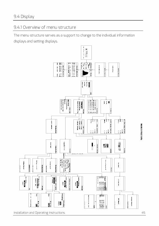
9.4.1 Overview of menu structure
The menu structure serves as a support to change to the individual information
displays and setting displays.

46 Installation and Operating Instructions
9.4.2 Initial page When the inverter starts up, LCD will first display an initial page that shows the current safety standard of the inverter. The page will display for about 5 seconds and then jump to the home page automatically.
9.4.3 Unlock page When the LCD backlighted, you must be slip from ‘Down’ to ‘Esc’ to unlock to operate the LCD.
9.4.4 Home page The home pageshows some of the most important running data of inverter such as the real-time output power, daily energy, an error code, and the power graph.

Installation and Operating Instructions 47
LCD will jump to the home page and the backlight will turn off when there is no button operation in 2 minutes.
Object Description
A Date&Time
B Output power
C Daily energy
D Total energy
E Error code(*), see chapter 9.3
F Checking time
G Operating status: waiting, operating, fault
H Field area of output power from 4:00 to 22:00
I Load limiting effective
(*) The inverter goes into fault mode when the temperature is lower than -25°C. LCD will show the error message “Temp.under -25°C”.
9.4.5 Operation information
There are two pages show the operational information on the AC&DC side of the inverter respectively. Switch between these 2 pages by pressing the “▲” or “▼” button.

48 Installation and Operating Instructions
Object Description
A Grid voltage
B Power factor
C Grid frequency
D Output current
E Phase leading or lagging
F Running hours of the current day
G DC input voltage
H DC input power of MPPT 1
I DC input current
J DC input power of MPPT 2
9.4.6 Main menu
Press the " " button to enter the main menu from the home page. Press the ▼ ▲" " or " " button to select the menu item.
Press the " " buttonto confirm. Press the "ESC" button to return to the home page.
9.4.7 Statistics
Press the ▲ ▼" " or " " button to select the "Statistics" item of main menu and
press " " button to confirm. Press the "▲" or "▼" button to select Daily historical data, Monthly historical dataor Yearly historical data.
Press the " " button to confirm. Press the ▲" " button one timeto display the previous history record. Press the ▼" " button one timeto displaythe next history record.

Installation and Operating Instructions 49
Press the "ESC" button to return to the menu.
9.4.8 Event log Press the "▲" or "▼" button to select the "Event Log" item of main menu
and press the " " button to confirm. Press the "▲" or "▼" button to check the fault messages. Press the "ESC" button to return to the menu.
Object Description
A Date and time of the fault
B Error code
9.4.9 Date&Time setting Enter the sub-menu “Basic Setting” and press the "▼" or "▲" button to select the "Date&Time Setting" item of the “Settings” sub-menu and press
the " " button to confirm. Use the "▲"or "▼"button to set the year, month, day, hour and minute one by one.
Press the " " button to confirm. Press the "ESC" button to return to the Basic Setting page.

50 Installation and Operating Instructions
9.4.10 Language setting
Enter the sub-menu “Basic Setting” and press the "▼" or "▲" button to select
the "Language Setting" and press the " " button to confirm. Use the "▲" or "▼" to choose the language.
Press the " " button to confirm. Press the "ESC" button to return to the Basic Setting page.
Language
DeutschEnglish
简体中文繁體中文
9.4.11 Contrast setting Enter the sub-menu “Basic Setting” and press the "▼" or "▲" button to select
the "Contrast Setting" and press the " " button to confirm. Use the "▲" or "▼" to choose the LCD contrast.
Press the " " button to save. Press the "ESC" button to return to the Basic Setting page.

Installation and Operating Instructions 51
The safety of the grid may be influenced due to the wrong safety setting!
The default parameters settings comply with the local regulations.
Don’t change the values of the monitored operating limits unless the utility provider agrees
with your requirement!
9.4.12 Safety regulations setting
Enter the sub-menu “Advanced Setting” and press the " " button to input the password. The password is required if you want to change some parameters.
Please get the correct password from the service engineer. Enter the correct
password and " " to enter the advanced setting sub-menu page.
Then select the “Safety Setting” item and press the " " button then enter the safety parameters page.
At the safety regulation parameter page, use the "▲" or "▼" button to modify the
selected parameter and confirm with the " " button. Then modify the next parameter in turn. Parameter modification is finished after the Enter key is pressed.
Press the "ESC" button to cancel.
There are two pages for safety regulation parameters setup. After modifying the
last parameter of the first page, the page will automatically jump to the second
page.

52 Installation and Operating Instructions
9.4.13 Overload setting Enter the sub-menu “Advanced Setting” and press the "▼" or "▲" button to select the
"Overload Setting" and press the " " button to set the status. Use the "▲" or "▼" to choose “Enable” or “Disable”.
Press the " " button to confirm this function is effective on the inverter. Press the "ESC" button to return to the Advanced Setting page.
9.4.14 Active power control
Enter the sub-menu “Advanced Setting” and press the "▼" or "▲" button to select the
"Active Power Control" and press the " " button to set the status. Use the "▲" or "▼" to choose the active power of the status.
Press the " " button to confirm this function is effective on the inverter. Press the "ESC" button to return to the Advanced Setting page.

Installation and Operating Instructions 53
9.4.15 Reactive power control
Enter the “Advanced Setting” menu and press the "▼" or "▲" button to select the
"Reactive Power Control" and press the " " button to enter the sub menu.
Select the “PF Enabling” item and press “Enter” to enter the PF Enabling page. Then press "▲" or "▼" button to disable or enable the function. Press “Enter” button to enter the reactive power control menu.
Choose the “PF Setting” item and press”Enter” button toenter the PF Setting page. Use the "▲" or "▼" to choose the reactive powercontrol mode “Default” or “Fixed”. Choose the “Default” and press”Enter” button to restore the PF parameters to factory setting. You can set a fixed PF and phase to the inverter when choose the “Fixed” mode. Use the "▲" or "▼". Choose the “Fixed” mode and press”Enter” button. Then you can modify the PF and phase in turn.
Press the " " button to confirm this function is effective on the inverter.

54 Installation and Operating Instructions
You should enable the function in the “PF Enabling” page first to make sure the PF setting effective.
Press the "ESC" button to return previous menu.
9.4.16 PV Mode setting
Enter the sub-menu “Advanced Setting” and press the "▼" or "▲" button to
select the "PV Mode Setting" and press the " " button to set the status. Use the "▲" or "▼" to choose the PV Mode.
Press the " " button to confirm this function is effective on the inverter. Press the "ESC" button to return to the Advanced Setting page.
Installation and Operating Instructions 55
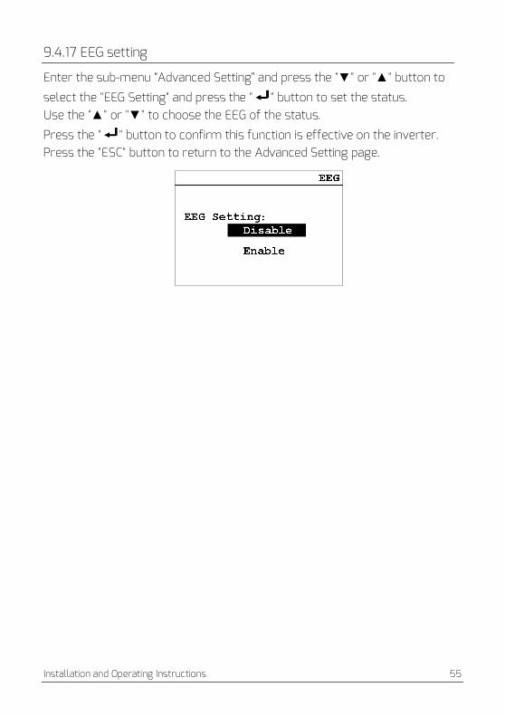
9.4.17 EEG setting
Enter the sub-menu “Advanced Setting” and press the "▼" or "▲" button to
select the "EEG Setting" and press the " " button to set the status. Use the "▲" or "▼" to choose the EEG of the status.
Press the " " button to confirm this function is effective on the inverter. Press the "ESC" button to return to the Advanced Setting page.

56 Installation and Operating Instructions
9.4.18 Communication setting
Select the “Communication Setting” item with the "▼" or "▲" button in the
“Settings” sub-menu and press “ ” button to enter the setting page. Use the "▲" or "▼" to choose the Modbusaddress.
Press the " " button to confirm this function is effective on the inverter. Press the "ESC" button to return to the menu.
9.4.19 Device information
▼ ▲Press the " " or " " button to select the "Device Info" item of the main
menu and press the " " button to confirm.Press the "ESC" button to return to the menu.

Installation and Operating Instructions 57
9.4.20 Clear the history data
Enter the "safety setting" page, enter the correct password, and enter the data clear page.
Press the " " button to confirm to clear the historical data. Press the “ESC” button to cancel.

58 Installation and Operating Instructions
10 Technical data
10.1 DC input data
Type TLC8000 TLC10000
DC convertible power (@cos =1)φ 9250W 10500W
Max. input voltage 1000V
MPP voltage range / rated input voltage 200-900V / 640V
Min. start voltage 250V
Min. feed-in power 12W
Max. input current per MPPT 15A/11A
Number of MPPTs 2
Number of independent MPP inputs 2/1
10.2 AC output data
Type TLC8000 TLC10000
Rated active power 8000W 10000W
Max. apparent AC power 8800W(3) 10000W
Nominal AC voltage 3/N/PE, 220/380V, 230/400V, 240/415V
Nominal AC voltage range (line to line) (4) 277-520V 277-520V
AC power frequency / range(5) 50 / +-5Hz
Rated power frequency / rated grid voltage 50Hz / 230V
Max. output current 3×13.3A 3×15.1A
Power factor (@rated power) > 0.99
Adjustable displacement power factor 0.85 inductive ... 0.85 capacitive
Feed-in phases / connection phases 3 / 3
Harmonic distortion (THD) at rated output < 3%
(3) Onlywhen overload is enable, this power can be reached. (4) The AC voltage range depends on the local safety standards. (5) The AC frequency range depends on the local safety standards.
Installation and Operating Instructions 59
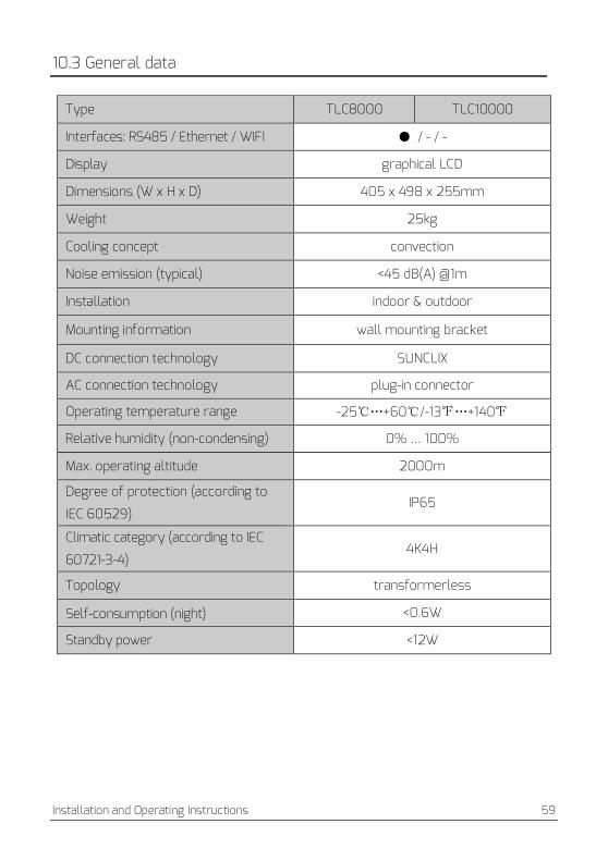
10.3 General data
Type TLC8000 TLC10000
Interfaces: RS485 / Ethernet / WIFI ● / - / -
Display graphical LCD
Dimensions (W x H x D) 405 x 498 x 255mm
Weight 25kg
Cooling concept convection
Noise emission (typical) <45 dB(A) @1m
Installation indoor & outdoor
Mounting information wall mounting bracket
DC connection technology SUNCLIX
AC connection technology plug-in connector
Operating temperature range -25℃…+60℃/-13℉…+140℉
Relative humidity (non-condensing) 0% … 100%
Max. operating altitude 2000m
Degree of protection (according to
IEC 60529) IP65
Climatic category (according to IEC
60721-3-4) 4K4H
Topology transformerless
Self-consumption (night) <0.6W
Standby power <12W

60 Installation and Operating Instructions
INFORMATION If you choose the standard VDE-AR-N 4105, please refer to information below.
•If a central NS protection device is used for power generation system, then the value of the
rise-in-voltage protection U > of 1.1Un presented in the integrated NS protection can be
changed, but need password.
10.4 Safety regulations
Type TLC8000 TLC10000
DC isolator ○
PV iso / Grid monitoring ● / ●
DC reverse polarity protection / AC short-
circuit current capability ● / ●
Residual current monitoring(GFCI) function ●
Protection class (according to IEC 62103) /
overvoltage category (according to IEC
60664-1)
I / II (DC), III (AC)
Internal overvoltage protection Integrated
DC feed-in monitoring Integrated
Islanding protection Integrated (Three-phase
monitoring)
EMC immunity EN61000-6-1, EN61000-6-2
EMC emission EN61000-6-3, EN61000-6-4
Utility interference EN61000-3-2, EN61000-3-3
1) Certification roadmap completed in Q3-2015. Please refer to our local sales organization for detailed information.
2) ● standard ○ optional - not available
Installation and Operating Instructions 61
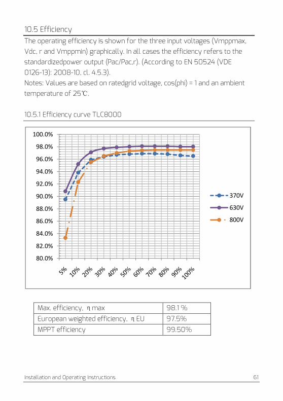
10.5 Efficiency The operating efficiency is shown for the three input voltages (Vmppmax, Vdc, r and Vmppmin) graphically. In all cases the efficiency refers to the standardizedpower output (Pac/Pac,r). (According to EN 50524 (VDE 0126-13): 2008-10, cl. 4.5.3). Notes: Values are based on ratedgrid voltage, cos(phi) = 1 and an ambient temperature of 25℃. 10.5.1 Efficiency curve TLC8000
Max. efficiency, maxη 98.1 %
European weighted efficiency, EUη 97.5%
MPPT efficiency 99.50%
80.0%
82.0%
84.0%
86.0%
88.0%
90.0%
92.0%
94.0%
96.0%
98.0%
100.0%
370V
630V
800V

62 Installation and Operating Instructions
10.5.2 Efficiency curve TLC10000
Max. efficiency, mη ax 98.1 %
European weighted efficiency, EUη 97.6%
MPPT efficiency 99.50%
84.00%
86.00%
88.00%
90.00%
92.00%
94.00%
96.00%
98.00%
100.00%
460V
630V
800V

Installation and Operating Instructions 63
10.6 Power reduction In order to ensure inverter operation under safe conditions, the device may automatically decrease power output. Power reduction depends on many operating parameters including ambient temperature and input voltage, grid voltage, grid frequency and power available from the PV modules. This device can decrease power output during certain periods of the day according to these parameters. Notes: Values based on ratedgrid voltage andcos (phi) = 1.
Power reduction with increased ambient temperature (TLC8000)
Power reduction with increased ambient temperature (TLC10000)
0100020003000400050006000700080009000
25 30 35 40 45 50 55 60 65 70 75 80460Vmppt 780Vmppt 640Vmppt
0
2000
4000
6000
8000
10000
12000
25 30 35 40 45 50 55 60 65 70 75 80460Vmppt 780Vmppt

64 Installation and Operating Instructions
11 Troubleshooting
Whenthe PV systemdoes notoperate normally, we recommend the following solutions for quick troubleshooting. When system is in fault condition, fault information will be show up outlet display and monitor device, the red LED will light up. The corresponding causes are described in section 9.3 “Display messages”. The correspondingcorrective measures are as follows:
Object Error
code
Corrective measures
Resumable
Fault
33
•Check the grid frequencyand observe how often majorfluctuations
occur.
If this faultis caused by frequent fluctuations, try to modify
theoperating parameters after informing the utilityprovider first.
34
•Check the grid voltage and grid connection on the inverter.
•Check the grid voltage at the point ofconnection of the inverter.
If the grid voltage is outside the permitted range due to local grid
conditions, try to modify the values of the monitored operating
limits after informing the electric utility company first.
If the grid voltage lies within the permitted range and this fault still
occurs, contact the service.
35
•Check the fuseand the triggering of AC circuit breakerin
thedistribution box.
•Check grid voltage, grid usability.
•Check AC cable, grid connection on the inverter.
If this fault is still being shown, contact the service.
36
•Make surethe earth connection of the inverter is reliable.
•Make a visual inspection of all PV cablesand modules.
If this fault is still shown, contact the service.
37
•Check the open-circuit voltages of the strings, make sure it is lower
than the Max. DC input voltage of the inverter.
If the input voltage lies within the permitted range andthe fault still
occurs, contact the service.

Installation and Operating Instructions 65
Resumable
Fault
38
•Check the PV generator’s insulation to earth, make sure that the
insulation resistance to earth is greater than 1MOhm; Otherwise,
make a visual inspection of all PV cablesand modules.
•Make surethe earth connection of the inverter is reliable.
If this fault occurs often, contact the service.
40
•Check whether the airflow to the heat sink is obstructed.
•Check whether the ambient temperature around the inverter is too
high.
41, 42
43, 44
•Disconnect the inverter from the grid and the PV generator,
reconnect them after 3 minutes.
If this fault is still being shown, contact the service.
46
•Check the open-circuit voltages of the strings, make sure it is lower
than the Max. DC input voltage of the inverter;
If the input voltage lies within the permitted range, and the fault still
occurs, maybe the internal circuit has broken, contact the service.
Permanent
Fault
1,2,3,4,8,
9,10,
11,39
Disconnect the inverter from the grid and the PV generator,
reconnect them after 3 minutes. If this fault is still being shown,
contact the service.

66 Installation and Operating Instructions
12 Maintenance
Normally, the inverter needs no maintenance or calibration. Regularly inspect the inverter and the cables for visible damage. Disconnect the inverter from all power sources before cleaning. Clean the enclosure and display with a soft cloth. Ensure the heatsink at the rear of the inverter is not covered.
12.1 Cleaning the contacts of the DC-switch Clean the contacts of the DC-switch once per year. Perform cleaning by cycling the switch to “1” and “0” positions 5 times. The DC-switch is located at the lower left of theenclosure.
12.2 Cleaning the heat sink
Risk injury due to hot heat sink!
• The heat sink may exceed 70℃during operation. Do not touch the heatsink during operation.
•Wait approx.30 minutes before cleaning until the heatsink has cooled down.
Clean the heat sinkwithpressurized airor a soft brush.Do not use aggressive chemicals, cleaning solvents or strong detergents. For proper function and long service life, ensure free air circulationaround the heatsink.

Installation and Operating Instructions 67
13 Recycling and disposal Both the inverter and its transport packaging are predominantly made from
recyclable raw materials.
Do not dispose of the defective inverter and its accessories with normal
domestic waste.
INFORMATION
• Do not dispose of the product together with the household waste but
in accordance with the disposal regulations for electronic waste applicable
at the installation site.
14 Warranty
The warranty cardis enclosed with the package, whichalso can be downloadedat www.zeversolar.com if required.Please keep well the warranty card. When the customer needs warranty service during the warranty period, the customer must provide a copy of the invoice, warranty card, and ensure the electrical label of the inverter is legible. If these conditions are not met, Zeversolar has the right to refuse to provide with the relevant warranty service.

68 Installation and Operating Instructions
15 Contact If you have any technical problems concerning our products, please contact Zeversolar service.We require the following information in order to provide you with the necessary assistance: • Inverter device type • Inverter serial number • Type and number of connected PV modules • Error code • Mounting location • Warranty card ZeversolarFactory Warranty
The current warranty conditions come enclosed with your device. They are also available online at www.zeversolar.com and canbe downloaded and are available on paper from the usual sales channels if required.
Jiangsu ZeversolarNew EnergyCo., Ltd.
Tel.: +86 512 6937 0998 Fax: +86 512 6937 3159 Web: www.zeversolar.com Factory add.: No.588 Gangxing Road, Yangzhong Jiangsu, China Headquarters add.: Building 9, No.198 Xiangyang Road, Suzhou 215011, China