underwater granular flows down inclined planes
DESCRIPTION
Research paperTRANSCRIPT
Underwater granular flows down inclined planes
K. Kumar & K. SogaGeo-Mechanics Research Group, Department of EngineeringUniversity of Cambridge, UK
J-Y. DelenneIATE, UMR1208 INRA-CIRAD-Montpellier Supagro-UM2,University of Montpellier 2, France.
ABSTRACT: In this study, two-dimensional sub-grain scale numerical simulations are performed to under-stand the local rheology of dense granular flows in fluid. The Discrete Element (DEM) technique is coupledwith the Lattice Boltzmann Method (LBM), for fluid-grain interactions, to understand the evolution of im-mersed granular flows. The fluid phase is simulated using Multiple-Relaxation-Time LBM (LBM-MRT) fornumerical stability. The Eulerian nature of the LBM formulation, together with the common explicit time stepscheme of both LBM and DEM makes this coupling strategy an efficient numerical procedure for systems dom-inated by both grain–grain and grain–fluid interactions. In order to simulate interconnected pore space in 2D, areduction in the radius of the grains (hydrodynamic radius) is assumed during LBM computations. By varyingthe hydrodynamic radius of the grains, granular materials of different permeabilities can be simulated. A para-metric analysis is performed to assess the influence of the granular characteristics (initial packing, permeability,slope of the inclined plane) on the evolution of flow and run-out distances. The effect of hydrodynamic forcesand hydroplaning on the run-out evolution is analysed by comparing the mechanism of energy dissipation andflow evolution in dry and immersed granular flows. Voronoi tesselation was used to study the evolution of localdensity and water entrainment at the flow front.
1 INTRODUCTION
The flow of dense granular material is a com-mon phenomenon in engineering predictions, suchas avalanches, landslides, and debris-flow modelling.Despite the huge amount of research that has goneinto describing the behaviour of granular flows, aconstitutive equation that describes the overall be-haviour of a flowing granular material is still lacking.The initiation and propagation of submarine granu-lar flows depend mainly on the slope, density, andquantity of the material destabilised. Although certainmacroscopic models are able to capture the simplemechanical behaviours, the complex physical mech-anisms that occur at the grain scale, such as thydrody-namic instabilities, the formation of clusters, collapse,and transport, have largely been ignored (Topin et al.2011). The momentum transfer between the discreteand the continuous phases significantly affects the dy-namics of the flow (Peker and Helvac 2007). Grain-scale description of the granular material enriches themacro-scale variables, which poorly account for thelocal rheology of the materials. In order to describe
the mechanism of saturated and/or immersed gran-ular flows, it is important to consider both the dy-namics of the solid phase and the role of the ambi-ent fluid (Denlinger and Iverson 2001). In particular,when the solid phase reaches a high volume fraction,it is important to consider the strong heterogeneityarising from the contact forces between the grains, thedrag interactions which counteract the movement ofthe grains, and the hydrodynamic forces that reducethe weight of the solids inducing a transition fromdense compacted to a dense suspended flow (Meru-ane et al. 2010). The case of the collapse in presenceof an interstitial fluid has been less studied. In thispaper, we study the submarine granular flows in theinclined configuration. We study the effect of perme-ability, density and slope angle on the run-out evolu-tion.
2 LBM FORMULATION
The Lattice Boltzmann Method is a ‘micro-particle’based numerical time-stepping procedure for the so-lution of incompressible fluid flows. Consider a 2D
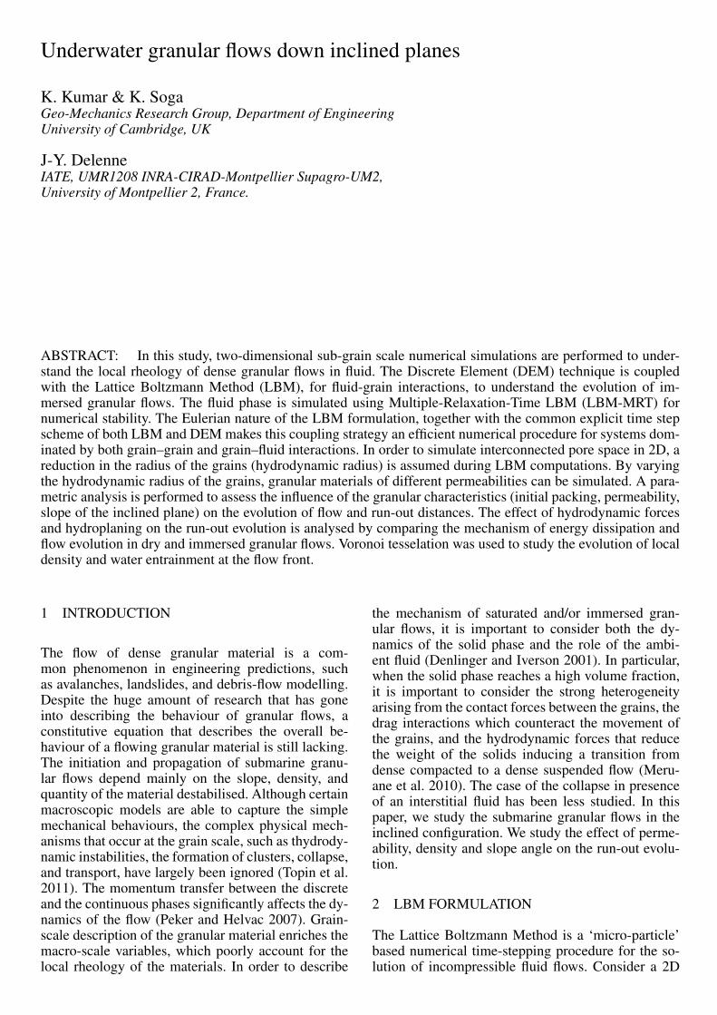
incompressible fluid flow with density ρ and kine-matic viscosity v, in a rectangular domain D. The fluiddomain is divided into a rectangular grid or lattice,with the same spacing ‘h’ in both the x- and the y-directions, as shown in figure 1. The present study fo-cuses on two-dimensional problems, hence the D2Q9momentum discretisation is adopted (see He et al.(1997) for naming convention).
Figure 1: The Lattice Boltzmann discretisation and D2Q9scheme: (a) a standard LB lattice and histogram views of the dis-crete single particle distribution function/direction-specific den-sities fi; (b) D2Q9 model
The lattice Boltzmann Bhatnagar-Gross-Krook(LGBK) method is capable of simulating various hy-drodynamics (Succi 2001) and offers intrinsic par-allelism. Although LBM is successful in modellingcomplex fluid systems, such as multiphase flows andsuspensions in fluid, the LBM may lead to numeri-cal instability when the dimensionless relaxation timeτ is close to 0.5. The Multi-Relaxation Time LatticeBoltzmann Method (LBM-MRT) overcomes the defi-ciencies of linearlised single relaxation LBM-BGK,such as fixed Prandtl number (Pr=ν/κ), where thethermal conductivity ‘κ’ is unity (Liu et al. 2003).The LB-MRT model offers better numerical stabilityand has more degrees of freedom. In the formulationof the linear Boltzmann equation with multiple relax-ation time approximation, the lattice Boltzmann equa-tion is written as:
fα(x + ei∆t, t+ ∆t) − fα(x, t)
= −Sαi(fi(x, t) − f eqi (x, t) (1)
where S is collision matrix. The nine eigen values ofS are all between 0 and 2 so as to maintain linear sta-bility and the separation of scales, which means thatthe relaxation times of non-conserved quantities aremuch faster than the hydrodynamic time scales. TheLGBK model is the special case in which the nine re-laxation times are all equal and the collision matrixS = 1
τI, where I is the identity matrix. The evolution-
ary progress involves two steps, advection and flux.The advection can be mapped to the momentum space
by multiplying through by a transformation matrix Mand the flux is still finished in the velocity space. Theevolutionary equation of the multi-relaxation time lat-tice Boltzmann equation is written as:
f(x + ei∆t, t+ ∆t) − f(x, t)
= −M−1S(f(x, t) − feq(x, t)) (2)
where M is the transformation matrix mapping a vec-tor f in the discrete velocity space V = Rb to a vectorf in the moment space V = Rb.
f = Mf (3)
f(x, t) = [f0(x, t), f1(x, t), . . . f8(x, t)]T (4)
The collision matrix S = MSM−1 in momentspace is a diagonal matrix: S = diag [s1, s2, s3, . . . s9].The transformation matrix M can be constructed viaGram-Schmidt orthgonalisation procedure. Throughthe Chapman-Enskog expansion (Du et al. 2006), theincompressible Navier-Stokes equation can be recov-ered and the viscosity is given as:
ν = c2s∆t(τ − 0.5) (5)
2.1 Turbulence in Lattice Boltzmann Method
Modelling fluids with low viscosity like water re-mains a challenge, necessitating very small values ofh, and/or τ very close to 0.5 (He et al. 1997). Turbu-lent flows are characterised by the occurrence of ed-dies with multiple scales in space, time and energy.In this study, the Large Eddy Simulation (LES) isadopted to solve for turbulent flow problems. The sep-aration of scales is achieved by filtering of the Navier-Stokes equations, from which the resolved scales aredirectly obtained and unresolved scales are modelledby a one-parameter Smagorinski sub-grid methodol-ogy, which assumes that the Reynold’s stress tensor isdependent only on the local strain rate (Smagorinsky1963). The turbulent viscosity ν is related to the strainrate Sij and a filtered length scale ‘h’ as follows:
vt = (Sch)2S; (6)
S =
√∑i ,j
Si ,j Si ,j (7)
where Sc is the Smagorinski constant found to beclose to 0.03 (Yu et al. 2005).
The effect of the unresolved scale motion is takeninto account by introducing an effective collision re-laxation time scale τt, so that the total relaxation timeτ∗ is written as:
τ∗ = τ + τt (8)
where τ and τt are respectively the standard relaxationtimes corresponding to the true fluid viscosity v andthe turbulence viscosity vt , defined by a sub-grid tur-bulence model. The new viscosity v∗ correspondingto τ∗ is defined as:
v∗ = v + vt =1
3(τ + τt −
1
2)C 2∆t (9)
vt =1
3τtC
2∆t (10)
The Smagorinski model is easy to implement and theLattice Boltzmann formulation remains unchanged,except for the use of a new turbulence-related vis-cosity τ∗. The component s1 of the collision matrixbecomes s1 = 1
τ+τt.
3 COUPLED LB - DEM FOR FLUID-PARTICLEINTERACTIONS
The Lattice Boltzmann approach has the advantage ofaccommodating large particle sizes and the interac-tion between the fluid and the moving particles canbe modelled through relatively simple fluid - parti-cle interface treatments. Further, employing the Dis-crete Element Method (DE) to account for the parti-cle/particle interaction naturally leads to a combinedLB - DEM solution procedure. The Eulerian nature ofthe Lattice Boltzmann formulation, together with thecommon explicit time step scheme of both the Lat-tice Boltzmann and the Discrete Element makes thiscoupling strategy an efficient numerical procedure forthe simulation of particle-fluid systems (Cook et al.2004). In order to capture the actual physical be-haviour of the fluid-particle system, the boundarycondition between the fluid and the particle is mod-elled as a non-slip boundary condition, i.e. the fluidnear the particle should have similar velocity as theparticle boundary. The solid particles inside the fluidare represented by lattice nodes. The discrete natureof lattice will result in stepwise representation of thesurfaces. Very small lattice spacing is adopted to ob-tain smoother boundaries.
4 UNDERWATER GRANULAR FLOWS
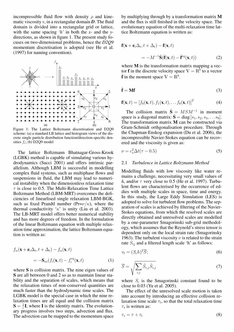
In this study, a 2D poly-disperse system(dmax/dmin = 1.8) of circular discs in fluid wasused to understand the behaviour of granular flows oninclined planes (see Figure 2). The soil column wasmodelled using 1000 discs of density 2650 kg m−3
and a contact friction angle of 26◦. The collapseof the column was simulated inside a fluid with adensity of 1000 kg m−3 and a kinematic viscosityof 1 × 10⁻⁶ m2 s−1. The choice of a 2D geometryhas the advantage of cheaper computational effortthan a 3D case, making it feasible to simulate verylarge systems. A granular column of aspect ratio ‘a’
of 0.8 was used. A hydrodynamic radius r = 0.9Rwas adopted during the LBM computations. Dryanalyses were also performed to study the effect ofhydrodynamic forces on the run-out distance.
Soil
Water
g
gate
Figure 2: Underwater granular collapse set-up
4.1 Effect of initial density
The morphology of the granular deposits in fluid isshown to be mainly controlled by the initial volumefraction of the granular mass and not by the aspectratio of the column (Rondon et al. 2011, Pailha et al.2008). In order to understand the influence of the ini-tial packing density on the run-out behaviour, a densesand column (initial packing density, Φ = 83%) and aloose sand column (Φ = 79%) were used. The granu-lar columns collapse and flow down slopes of varyinginclinations (2.5◦, 5◦ and 7.5◦).
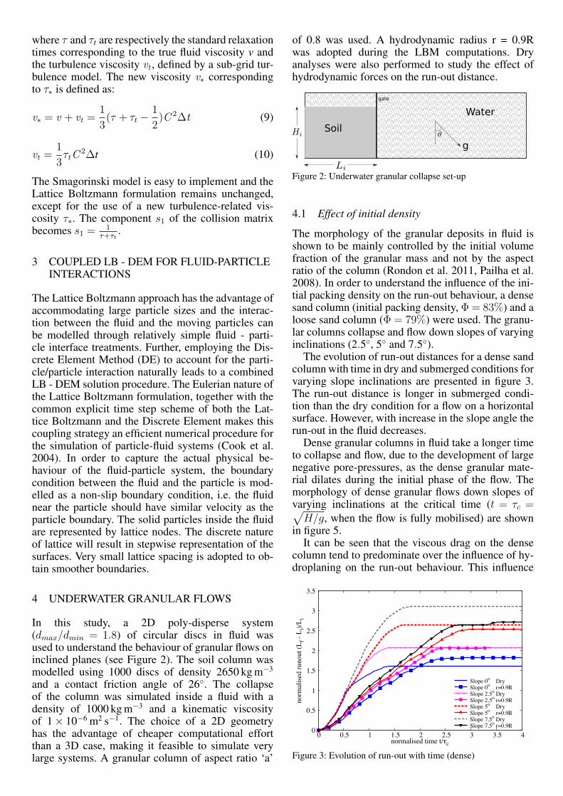
The evolution of run-out distances for a dense sandcolumn with time in dry and submerged conditions forvarying slope inclinations are presented in figure 3.The run-out distance is longer in submerged condi-tion than the dry condition for a flow on a horizontalsurface. However, with increase in the slope angle therun-out in the fluid decreases.
Dense granular columns in fluid take a longer timeto collapse and flow, due to the development of largenegative pore-pressures, as the dense granular mate-rial dilates during the initial phase of the flow. Themorphology of dense granular flows down slopes ofvarying inclinations at the critical time (t = τc =√H/g, when the flow is fully mobilised) are shown
in figure 5.It can be seen that the viscous drag on the dense
column tend to predominate over the influence of hy-droplaning on the run-out behaviour. This influence
0
0.5
1
1.5
2
2.5
3
3.5
0 0.5 1 1.5 2 2.5 3 3.5 4
norm
alise
d ru
nout
(Lf -
Li)/
L i
normalised time t/oc
Slope 0o DrySlope 0o r=0.9RSlope 2.5o DrySlope 2.5o r=0.9RSlope 5o DrySlope 5o r=0.9RSlope 7.5o DrySlope 7.5o r=0.9R
Figure 3: Evolution of run-out with time (dense)
0
0.02
0.04
0.06
0.08
0.1
0.12
0.14
0.16
0 0.5 1 1.5 2 2.5 3
norm
alise
d ki
netic
ene
rgy
(Ek/
E o)
normalised time t/oc
Slope 0o DrySlope 0o r=0.9RSlope 2.5o DrySlope 2.5o r=0.9RSlope 5o DrySlope 5o r=0.9RSlope 7.5o DrySlope 7.5o r=0.9R
Figure 4: Evolution of Kinetic Energy with time (dense case)
can be observed in the smaller peak kinetic energy forgranular column in fluid compared to it’s dry coun-terpart (see Figure 4). With increase in slope angle,the volume of material that dilates increases. This re-sults in large negative pore pressures and more vis-cous drag on the granular material. Hence, the dif-ference in the run-out between the dry and the sub-merged condition, for a dense granular assembly, in-creases with increase in the slope angle.
In contrast to the dense granular columns, theloose granular columns (relative density ID = 30%)show longer run-out distance in immersed conditions(see Figure 6). The run-out distance in fluid increaseswith increase in the slope angle compared to the dry
(a) Slope 2.5
(b) Slope 5.0
(c) Slope 7.5Figure 5: Flow morphology at critical time for different slopeangles (dense)
0
0.5
1
1.5
2
2.5
3
3.5
0 0.5 1 1.5 2 2.5 3 3.5 4
norm
alise
d ru
nout
(Lf -
Li)/
L i
normalised time t/oc
Slope 0o DrySlope 0o r=0.9RSlope 2.5o DrySlope 2.5o r=0.9RSlope 5o DrySlope 5o r=0.9RSlope 7.5o DrySlope 7.5o r=0.9R
Figure 6: Evolution of run-out with time (loose)
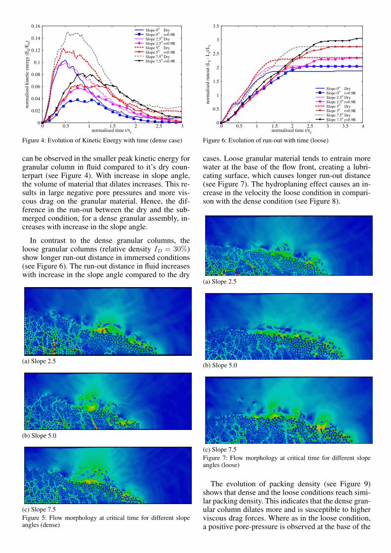
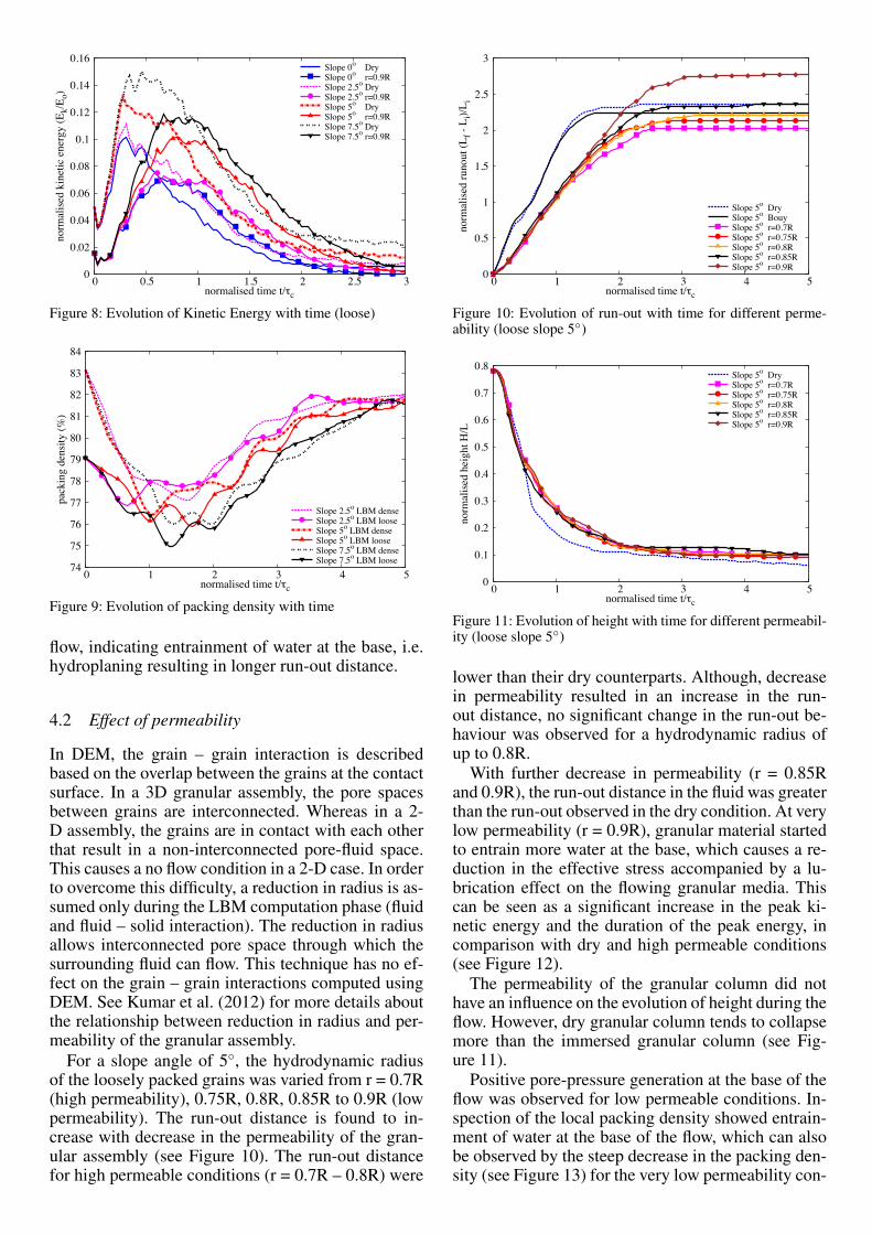
cases. Loose granular material tends to entrain morewater at the base of the flow front, creating a lubri-cating surface, which causes longer run-out distance(see Figure 7). The hydroplaning effect causes an in-crease in the velocity the loose condition in compari-son with the dense condition (see Figure 8).
(a) Slope 2.5
(b) Slope 5.0
(c) Slope 7.5Figure 7: Flow morphology at critical time for different slopeangles (loose)
The evolution of packing density (see Figure 9)shows that dense and the loose conditions reach simi-lar packing density. This indicates that the dense gran-ular column dilates more and is susceptible to higherviscous drag forces. Where as in the loose condition,a positive pore-pressure is observed at the base of the
0
0.02
0.04
0.06
0.08
0.1
0.12
0.14
0.16
0 0.5 1 1.5 2 2.5 3
norm
alise
d ki
netic
ene
rgy
(Ek/
E o)
normalised time t/oc
Slope 0o DrySlope 0o r=0.9RSlope 2.5o DrySlope 2.5o r=0.9RSlope 5o DrySlope 5o r=0.9RSlope 7.5o DrySlope 7.5o r=0.9R
Figure 8: Evolution of Kinetic Energy with time (loose)
74
75
76
77
78
79
80
81
82
83
84
0 1 2 3 4 5
pack
ing
dens
ity (%
)
normalised time t/oc
Slope 2.5o LBM denseSlope 2.5o LBM looseSlope 5o LBM denseSlope 5o LBM looseSlope 7.5o LBM denseSlope 7.5o LBM loose
Figure 9: Evolution of packing density with time
flow, indicating entrainment of water at the base, i.e.hydroplaning resulting in longer run-out distance.
4.2 Effect of permeability
In DEM, the grain – grain interaction is describedbased on the overlap between the grains at the contactsurface. In a 3D granular assembly, the pore spacesbetween grains are interconnected. Whereas in a 2-D assembly, the grains are in contact with each otherthat result in a non-interconnected pore-fluid space.This causes a no flow condition in a 2-D case. In orderto overcome this difficulty, a reduction in radius is as-sumed only during the LBM computation phase (fluidand fluid – solid interaction). The reduction in radiusallows interconnected pore space through which thesurrounding fluid can flow. This technique has no ef-fect on the grain – grain interactions computed usingDEM. See Kumar et al. (2012) for more details aboutthe relationship between reduction in radius and per-meability of the granular assembly.
For a slope angle of 5◦, the hydrodynamic radiusof the loosely packed grains was varied from r = 0.7R(high permeability), 0.75R, 0.8R, 0.85R to 0.9R (lowpermeability). The run-out distance is found to in-crease with decrease in the permeability of the gran-ular assembly (see Figure 10). The run-out distancefor high permeable conditions (r = 0.7R – 0.8R) were
0
0.5
1
1.5
2
2.5
3
0 1 2 3 4 5
norm
alise
d ru
nout
(Lf -
Li)/
L i
normalised time t/oc
Slope 5o DrySlope 5o BouySlope 5o r=0.7RSlope 5o r=0.75RSlope 5o r=0.8RSlope 5o r=0.85RSlope 5o r=0.9R
Figure 10: Evolution of run-out with time for different perme-ability (loose slope 5◦)
0
0.1
0.2
0.3
0.4
0.5
0.6
0.7
0.8
0 1 2 3 4 5
norm
alise
d he
ight
H/L
normalised time t/oc
Slope 5o DrySlope 5o r=0.7RSlope 5o r=0.75RSlope 5o r=0.8RSlope 5o r=0.85RSlope 5o r=0.9R
Figure 11: Evolution of height with time for different permeabil-ity (loose slope 5◦)
lower than their dry counterparts. Although, decreasein permeability resulted in an increase in the run-out distance, no significant change in the run-out be-haviour was observed for a hydrodynamic radius ofup to 0.8R.
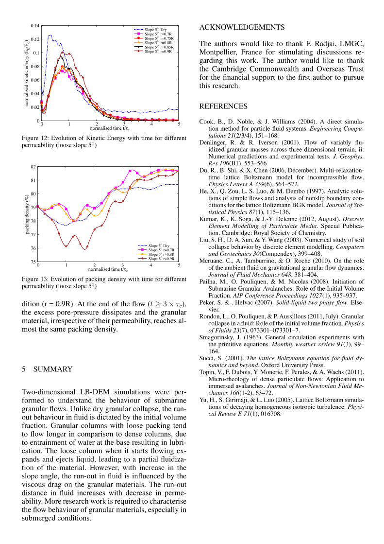
With further decrease in permeability (r = 0.85Rand 0.9R), the run-out distance in the fluid was greaterthan the run-out observed in the dry condition. At verylow permeability (r = 0.9R), granular material startedto entrain more water at the base, which causes a re-duction in the effective stress accompanied by a lu-brication effect on the flowing granular media. Thiscan be seen as a significant increase in the peak ki-netic energy and the duration of the peak energy, incomparison with dry and high permeable conditions(see Figure 12).
The permeability of the granular column did nothave an influence on the evolution of height during theflow. However, dry granular column tends to collapsemore than the immersed granular column (see Fig-ure 11).
Positive pore-pressure generation at the base of theflow was observed for low permeable conditions. In-spection of the local packing density showed entrain-ment of water at the base of the flow, which can alsobe observed by the steep decrease in the packing den-sity (see Figure 13) for the very low permeability con-
0
0.02
0.04
0.06
0.08
0.1
0.12
0.14
0 1 2 3 4 5
norm
alise
d ki
netic
ene
rgy
(Ek/
E o)
normalised time t/oc
Slope 5o DrySlope 5o r=0.7RSlope 5o r=0.75RSlope 5o r=0.8RSlope 5o r=0.85RSlope 5o r=0.9R
Figure 12: Evolution of Kinetic Energy with time for differentpermeability (loose slope 5◦)
75
76
77
78
79
80
81
82
0 1 2 3 4 5
pack
ing
dens
ity (%
)
normalised time t/oc
Slope 5o DrySlope 5o r=0.7RSlope 5o r=0.8RSlope 5o r=0.9R
Figure 13: Evolution of packing density with time for differentpermeability (loose slope 5◦)
dition (r = 0.9R). At the end of the flow (t ≥ 3 × τc),the excess pore-pressure dissipates and the granularmaterial, irrespective of their permeability, reaches al-most the same packing density.
5 SUMMARY
Two-dimensional LB-DEM simulations were per-formed to understand the behaviour of submarinegranular flows. Unlike dry granular collapse, the run-out behaviour in fluid is dictated by the initial volumefraction. Granular columns with loose packing tendto flow longer in comparison to dense columns, dueto entrainment of water at the base resulting in lubri-cation. The loose column when it starts flowing ex-pands and ejects liquid, leading to a partial fluidiza-tion of the material. However, with increase in theslope angle, the run-out in fluid is influenced by theviscous drag on the granular materials. The run-outdistance in fluid increases with decrease in perme-ability. More research work is required to characterisethe flow behaviour of granular materials, especially insubmerged conditions.
ACKNOWLEDGEMENTS
The authors would like to thank F. Radjai, LMGC,Montpellier, France for stimulating discussions re-garding this work. The author would like to thankthe Cambridge Commonwealth and Overseas Trustfor the financial support to the first author to pursuethis research.
REFERENCES
Cook, B., D. Noble, & J. Williams (2004). A direct simula-tion method for particle-fluid systems. Engineering Compu-tations 21(2/3/4), 151–168.
Denlinger, R. & R. Iverson (2001). Flow of variably flu-idized granular masses across three-dimensional terrain, ii:Numerical predictions and experimental tests. J. Geophys.Res 106(B1), 553–566.
Du, R., B. Shi, & X. Chen (2006, December). Multi-relaxation-time lattice Boltzmann model for incompressible flow.Physics Letters A 359(6), 564–572.
He, X., Q. Zou, L. S. Luo, & M. Dembo (1997). Analytic solu-tions of simple flows and analysis of nonslip boundary con-ditions for the lattice Boltzmann BGK model. Journal of Sta-tistical Physics 87(1), 115–136.
Kumar, K., K. Soga, & J.-Y. Delenne (2012, August). DiscreteElement Modelling of Particulate Media. Special Publica-tion. Cambridge: Royal Society of Chemistry.
Liu, S. H., D. A. Sun, & Y. Wang (2003). Numerical study of soilcollapse behavior by discrete element modelling. Computersand Geotechnics 30(Compendex), 399–408.
Meruane, C., A. Tamburrino, & O. Roche (2010). On the roleof the ambient fluid on gravitational granular flow dynamics.Journal of Fluid Mechanics 648, 381–404.
Pailha, M., O. Pouliquen, & M. Nicolas (2008). Initiation ofSubmarine Granular Avalanches: Role of the Initial VolumeFraction. AIP Conference Proceedings 1027(1), 935–937.
Peker, S. & . Helvac (2007). Solid-liquid two phase flow. Else-vier.
Rondon, L., O. Pouliquen, & P. Aussillous (2011, July). Granularcollapse in a fluid: Role of the initial volume fraction. Physicsof Fluids 23(7), 073301–073301–7.
Smagorinsky, J. (1963). General circulation experiments withthe primitive equations. Monthly weather review 91(3), 99–164.
Succi, S. (2001). The lattice Boltzmann equation for fluid dy-namics and beyond. Oxford University Press.
Topin, V., F. Dubois, Y. Monerie, F. Perales, & A. Wachs (2011).Micro-rheology of dense particulate flows: Application toimmersed avalanches. Journal of Non-Newtonian Fluid Me-chanics 166(1-2), 63–72.
Yu, H., S. Girimaji, & L. Luo (2005). Lattice Boltzmann simula-tions of decaying homogeneous isotropic turbulence. Physi-cal Review E 71(1), 016708.