ungs anleitung - toma
TRANSCRIPT
BedienungsanleitungOperating Instructions
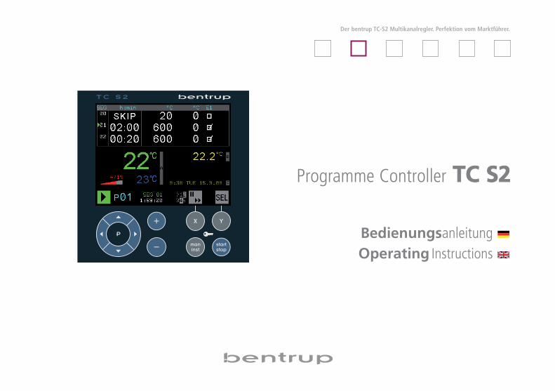
Der bentrup TC-S2 Multikanalregler. Perfektion vom Marktführer.
Programme Controller TTCC SS22
1operating instructions bentrup TC-S2 V1.1
Prog
ramme En
terin
gProg
ramme Ru
nMessage
s
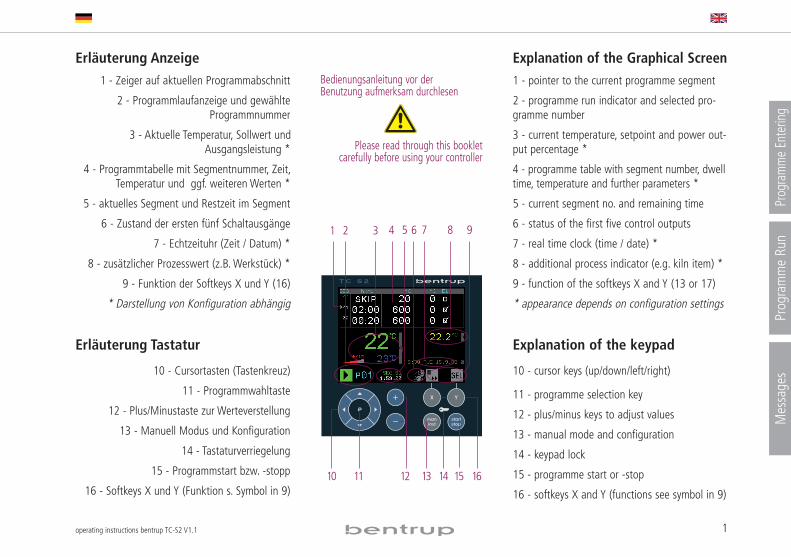
Erläuterung Anzeige1 - Zeiger auf aktuellen Programmabschnitt
2 - Programmlaufanzeige und gewählteProgrammnummer
3 - Aktuelle Temperatur, Sollwert undAusgangsleistung *
4 - Programmtabelle mit Segmentnummer, Zeit,Temperatur und ggf. weiteren Werten *
5 - aktuelles Segment und Restzeit im Segment
6 - Zustand der ersten fünf Schaltausgänge
7 - Echtzeituhr (Zeit / Datum) *
8 - zusätzlicher Prozesswert (z.B. Werkstück) *
9 - Funktion der Softkeys X und Y (16)
* Darstellung von Konfiguration abhängig
Erläuterung Tastatur
10 - Cursortasten (Tastenkreuz)
11 - Programmwahltaste
12 - Plus/Minustaste zur Werteverstellung
13 - Manuell Modus und Konfiguration
14 - Tastaturverriegelung
15 - Programmstart bzw. -stopp
16 - Softkeys X und Y (Funktion s. Symbol in 9)
Explanation of the Graphical Screen1 - pointer to the current programme segment
2 - programme run indicator and selected pro-gramme number
3 - current temperature, setpoint and power out-put percentage *
4 - programme table with segment number, dwelltime, temperature and further parameters *
5 - current segment no. and remaining time
6 - status of the first five control outputs
7 - real time clock (time / date) *
8 - additional process indicator (e.g. kiln item) *
9 - function of the softkeys X and Y (13 or 17)
* appearance depends on configuration settings
Explanation of the keypad
10 - cursor keys (up/down/left/right)
11 - programme selection key
12 - plus/minus keys to adjust values
13 - manual mode and configuration
14 - keypad lock
15 - programme start or -stop
16 - softkeys X and Y (functions see symbol in 9)
7654321 8 9
10 1615141311 12
Bedienungsanleitung vor derBenutzung aufmerksam durchlesen
Please read through this bookletcarefully before using your controller
2 operating instructions bentrup TC-S2 V1.1
Programme Entering
Vorwort
Der bentrup TC-S2 vereint modernste Regelungs -technik bei einfachster Handhabung. Er ist einleistungsfähiger, Multi kanal-Kompaktregler derhöchste Ansprüche an Sicherheit und Genauigkeiterfüllt.Die Regler struktur wird werksseitig auf IhreAnwengung konfiguriert. Sehen sie die TechnischeAnleitung auf www.bentrup.de zur Installation.
Programmeingabe
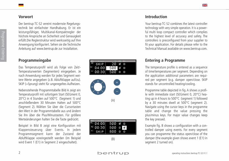
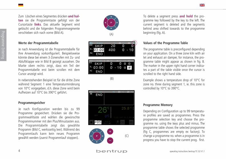
Das Temperaturprofil wird als Folge von Zeit/ -Temperaturwerten (Segmenten) eingegeben. Jenach Anwendung werden für jedes Segment wei-tere Werte angegeben (z.B. Abluftklappe auf/zu).SKIP (=Sprung) steht für ungeregeltes Aufheizen.
Nebenstehende Programmtabelle Bild A zeigt einTemperaturprofil mit sofortigem Start (SEGment 0,20°C) in 4 Stunden auf 500°C (Segment 1) undanschließendem 30 Minuten Halten auf 500°C(Segment 2). Wählen Sie über die Cursortastenden Wert in der Programmtabelle aus und ändernSie ihn über die Plus/Minustasten. Für größereWerte änderungen halten Sie die Taste gedrückt.
Beispiel in Bild B zeigt eine Konfiguration mitKlappensteuerung über Events. In jedemProgrammsegment kann der Zustand derAbluftklappe voreingestellt werden (im Beispielwird Event 1 (E1) in Segment 2 eingeschaltet).
Introduction
Your bentrup TC-S2 combines the latest controllertechnology with very simple operation. It is a power -ful multi loop compact controller which compliesto the highest level of accuracy and safety. Thecontrollers is preconfigured from your supplier tofit your application. For details please refer to theTechnical Manual available on www.bentrup.com.
Entering a Programme
The temperature profile is entered as a sequenceof time/temperatures per segment. Depen ding onthe application additional parameters are requi-red per segment (e.g. damper open/close. SKIPstands for uncontrolled heating/cooling.
Programme table depicted in fig. A shows a profi-le with immediate start (SEGment 0, 20°C) hea-ting up in 4 hours to 500°C (segment 1) followedby a 30 minutes dwell at 500°C (segment 2).Navigate using the cursor keys in the programmetable and change the value pressing theplus/minus keys. For major value changes keepthe key pressed.
Example fig. B shows a configuration with a con-trolled damper using events. For every segmentyou can programme the status open/close of thedamper (the example given shows event 1 (E1) insegment 2 turned on).
(A)
(B)
3operating instructions bentrup TC-S2 V1.1
Prog
ramme En
terin
g
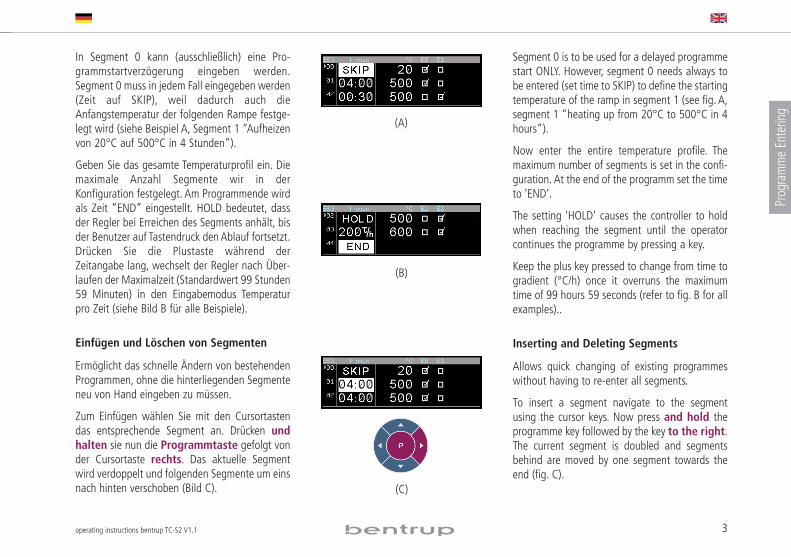
In Segment 0 kann (ausschließlich) eine Pro -gramm start verzögerung eingeben werden.Segment 0 muss in jedem Fall eingegeben werden(Zeit auf SKIP), weil dadurch auch dieAnfangstemperatur der folgenden Rampe festge-legt wird (siehe Beispiel A, Segment 1 “Aufheizenvon 20°C auf 500°C in 4 Stunden”).
Geben Sie das gesamte Temperaturprofil ein. Diemaximale Anzahl Segmente wir in derKonfiguration festgelegt. Am Programmende wirdals Zeit “END” eingestellt. HOLD bedeutet, dassder Regler bei Erreichen des Segments anhält, bisder Benutzer auf Tastendruck den Ablauf fortsetzt.Drücken Sie die Plustaste während derZeitangabe lang, wechselt der Regler nach Über-laufen der Maximalzeit (Standardwert 99 Stunden59 Minuten) in den Eingabemodus Tem peraturpro Zeit (siehe Bild B für alle Beispiele).
Einfügen und Löschen von Segmenten
Ermöglicht das schnelle Ändern von bestehendenProgrammen, ohne die hinterliegenden Segmenteneu von Hand eingeben zu müssen.
Zum Einfügen wählen Sie mit den Cursortastendas entsprechende Segment an. Drücken undhalten sie nun die Programmtaste gefolgt vonder Cursortaste rechts. Das aktuelle Segmentwird verdoppelt und folgenden Segmente um einsnach hinten verschoben (Bild C).
Segment 0 is to be used for a delayed programmestart ONLY. However, segment 0 needs always tobe entered (set time to SKIP) to define the startingtemperature of the ramp in segment 1 (see fig. A,segment 1 “heating up from 20°C to 500°C in 4hours”).
Now enter the entire temperature profile. Themaximum number of segments is set in the confi-guration. At the end of the programm set the timeto ‘END’.
The setting ‘HOLD’ causes the controller to holdwhen reaching the segment until the operatorcontinues the programme by pressing a key.
Keep the plus key pressed to change from time togradient (°C/h) once it overruns the maximumtime of 99 hours 59 seconds (refer to fig. B for allexamples)..
Inserting and Deleting Segments
Allows quick changing of existing programmeswithout having to re-enter all segments.
To insert a segment navigate to the segmentusing the cursor keys. Now press and hold theprogramme key followed by the key to the right.The current segment is doubled and segmentsbehind are moved by one segment towards theend (fig. C).
(A)
(B)
(C)
4 operating instructions bentrup TC-S2 V1.1
Programme Entering
Zum Löschen eines Segmentes drücken und hal-ten sie die Programmtaste gefolgt von derCursortaste links. Das aktuelle Segment wirdgelöscht und die folgenden Programmsegmenteverschieben sich nach vorne (Bild A).
Werte der Programmtabelle
Je nach Anwendung ist die Programmtabelle fürIhre Anwendung vorkonfiguriert. Beispielsweisekönnte diese bei einem 3-Zonenofen mit Zu- undAbluft klappe wie in Bild B gezeigt aussehen. DieMarke oben rechts zeigt, dass ein Teil derProgrammtabelle erst beim scrollen mit demCursor anzeigt wird.
In nebenstehenden Beispiel ist für die dritte Zonewährend Segment 1 eine Temperatur minderungvon 10°C vorgegeben, d.h. diese Zone wird beimAufheizen auf 10°C bis 390°C geführt.
Programmspeicher
Je nach Konfiguration werden bis zu 99Programme gespeichert. Drücken sie die Pro -gramm wahltaste und wählen die gewünschteProgrammnummer mit den Plus/Minustasten aus.Die Programmtabelle zeigt das gewählteProgramm (Bild C, werksseitig leer). Während desProgrammlaufs kann kein neues Programmgewählt werden (zuerst Programmlauf stoppen).
To delete a segment press and hold the pro-gramme key followed by the key to the left. Thecurrent segment is deleted and the segmentsbehind area shifted towards to the programmebeginning (fig. A).
Values of the Programme Table
The programme table is preconfigured dependingon your application. On a three zone kiln with airlet and exhaust air damper, for instance, the pro-gramme table might appear as shown in fig. B.The marker in the upper right hand corner indica-tes a part of the table visible once the cursor isscrolled to the right hand side.
Example shows a temperature drop of 10°C forzone no. three during segment 1, ie. this zone iscontrolled by 10°C to 390°C.
Programme Memory
Depending on Configuration up to 99 temperatu-re profiles are saved as programmes. Press theprogramme selection key and choose the pro-gramme no. using the keys plus and minus. Theprogramme table shows the selected programme(fig C, programmes are empty ex factory). Tochange a programme no. when a programme is inprogress you have to stop the current prog. first.
(B)
(A)
(C)
5operating instructions bentrup TC-S2 V1.1
Prog
ramme Ru
n
Programmlauf
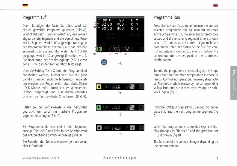
Durch Betätigen der Taste Start/Stop wird dasaktuell gewählte Programm gestartet (Bild A).Symbol (b) zeigt ‘Programmlauf’ an, das aktuellabgearbeitete Segment und die berechnete Rest -zeit im Segment wird in (c) angezeigt. (a) zeigt inder Programmtabelle ebenfalls auf das aktuelleSegment. Der Zustand der ersten fünf Schalt -ausgänge wird in (d) angezeigt (invertiert = an).Die Bedeutung der Schaltausgänge (z.B. ‘HeizenZone 1’) wird in der Konfiguration festgelegt.
Über die Softkey-Taste X kann der Programmlaufangehalten werden; hierbei wird die Zeit (unddamit in Rampen auch die Temperatur) angehal-ten werden, der Regler bleibt aber aktiv. DieserHOLD-Modus wird durch ein entsprechendesSymbol angezeigt und erst durch erneutesDrücken der Softkey-Taste X verlassen (Bild B).
Halten sie die Softkey-Taste X drei Sekundengedrückt, um sofort ins nächste Programm -segment zu springen (Bild C).
Bei Programmende erscheint in der Segment -anzeige “finished” und links in der Anzeige wirddas entsprechende Symbol angezeigt (Bild D).
Die Funktion der Softkeys wechselt je nach aktu-eller Erfordernis.
Programme Run
Press the key start/stop to commence the currentselected programme (fig. A). Icon (b) indicatesactive programme run, the segment currently pro-cessed and the remaining segment time is shownin (c). (a) points to the current segment in theprogramme table. The status of the first five con-trol outputs is shown in (d), invers = active. Thecontrol outputs are assigned in the controllersconfiguration.
To hold the programme press softkey X; this stopstime count and therefore temperature increase inramps. Controlling operation, however, stays acti-ve. The hold mode is shown by the correspondingyellow icon and is released by pressing the soft-key X again (fig. B).
Hold the softkey X pressed for 3 seconds to imme-diate skip into the next programme segment (figC).
When the programme is completed segment dis-play changes to “finished” and the grey icon forIDLE is shown (fig D).
The function of the softkey changes depending onthe current demand.
(A)
(B)
(a)
(b) (c) (d)
(C)
(D)
6 operating instructions bentrup TC-S2 V1.1
Programme Run
Anzeige der Prozesswerte
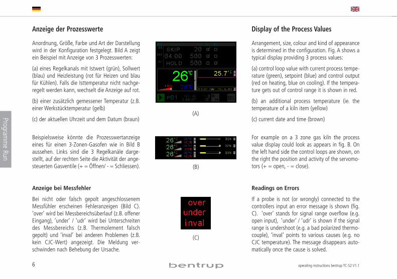
Anordnung, Größe, Farbe und Art der Darstellungwird in der Konfiguration festgelegt. Bild A zeigtein Beispiel mit Anzeige von 3 Prozesswerten:
(a) eines Regelkanals mit Istwert (grün), Sollwert(blau) und Heizleistung (rot für Heizen und blaufür Kühlen). Falls die Isttemperatur nicht nachge-regelt werden kann, wechselt die Anzeige auf rot.
(b) einer zusätzlich gemessener Temperatur (z.B.einer Werkstücktemperatur (gelb)
(c) der aktuellen Uhrzeit und dem Datum (braun)
Beispielsweise könnte die Prozesswertanzeigeeines für einen 3-Zonen-Gasofen wie in Bild Baussehen. Links sind die 3 Regelkanäle darge-stellt, auf der rechten Seite die Aktivität der ange-steuerten Gasventile (+ = Öffnen/ - = Schliessen).
Anzeige bei Messfehler
Bei nicht oder falsch gepolt angeschlossenemMessfühler erscheinen Fehleranzeigen (Bild C).‘over’ wird bei Messbereichsüberlauf (z.B. offenerEingang), ‘under’ / ’udr’ wird bei Unterschreitendes Messbereichs (z.B. Thermolement falschgepolt) und ‘inval’ bei anderen Problemen (z.B.kein CJC-Wert) angezeigt. Die Meldung ver-schwinden nach Behebung der Ursache.
Display of the Process Values
Arrangement, size, colour and kind of appearanceis determined in the configuration. Fig. A shows atypical display providing 3 process values:
(a) control loop value with current process tempe-rature (green), setpoint (blue) and control output(red on heating, blue on cooling). If the tempera-ture gets out of control range it is shown in red.
(b) an additional process temperature (ie. thetemperature of a kiln item (yellow)
(c) current date and time (brown)
For example on a 3 zone gas kiln the processvalue display could look as appears in fig. B. Onthe left hand side the control loops are shown, onthe right the position and activity of the servomo-tors (+ = open, - = close).
Readings on Errors
If a probe is not (or wrongly) connected to thecontrollers input an error message is shown (fig.C). ‘over’ stands for signal range overflow (e.g.open input), ‘under’ / ’udr’ is shown if the signalrange is undershoot (e.g. a bad polarized thermo-couple), ‘inval’ points to various causes (e.g. noCJC temperature). The message disappears auto-matically once the cause is solved.
(A)
(B)
(C)
7operating instructions bentrup TC-S2 V1.1
Prog
ramme Ru
n
Anzeigen im Regelkanal
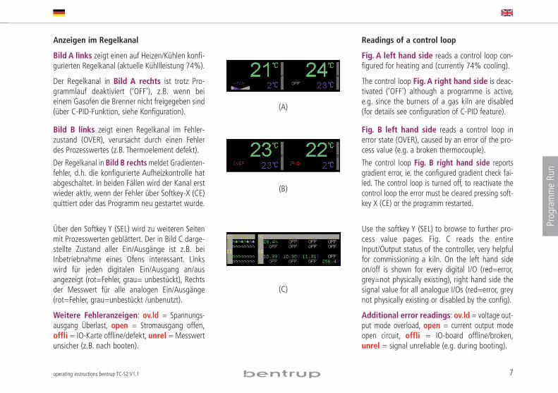
Bild A links zeigt einen auf Heizen/Kühlen konfi-gurierten Regelkanal (aktuelle Kühllleistung 74%).
Der Regelkanal in Bild A rechts ist trotz Pro -grammlauf deaktiviert (‘OFF’), z.B. wenn beieinem Gasofen die Brenner nicht freigegeben sind(über C-PID-Funktion, siehe Konfiguration).
Bild B links zeigt einen Regelkanal im Fehler -zustand (OVER), verursacht durch einen Fehlerdes Prozesswertes (z.B. Thermo ele ment defekt).
Der Regelkanal in Bild B rechtsmeldet Gradien ten -fehler, d.h. die konfigurierte Aufheizkontrolle hatabgeschaltet. In beiden Fällen wird der Kanal erstwieder aktiv, wenn der Fehler über Softkey-X (CE)quittiert oder das Programm neu gestartet wurde.
Über den Softkey Y (SEL) wird zu weiteren Seitenmit Prozesswerten geblättert. Der in Bild C darge-stellte Zustand aller Ein/Ausgänge ist z.B. beiInbetriebnahme eines Ofens interessant. Linkswird für jeden digitalen Ein/Ausgang an/ausangezeigt (rot=Fehler, grau= unbestückt), Rechtsder Messwert für alle analogen Ein/Ausgänge(rot=Fehler, grau=unbestückt /unbenutzt).
Weitere Fehleranzeigen: ov.ld = Spannungs -aus gang Überlast, open = Strom aus gang offen,offli = IO-Karte offline/defekt, unrel = Messwertunsicher (z.B. nach booten).
Readings of a control loop
Fig. A left hand side reads a control loop con-figured for heating and (currently 74% cooling).
The control loop Fig. A right hand side is deac-tivated (‘OFF’) although a programme is active,e.g. since the burners of a gas kiln are disabled(for details see configuration of C-PID feature).
Fig. B left hand side reads a control loop inerror state (OVER), caused by an error of the pro-cess value (e.g. a broken thermocouple).
The control loop Fig. B right hand side reportsgradient error, ie. the configured gradient check fai-led. The control loop is turned off, to reactivate thecontrol loop the error must be cleared pressing soft-key X (CE) or the programm restarted.
Use the softkey Y (SEL) to browse to further pro-cess value pages. Fig. C reads the entireInput/Output status of the controller, very helpfulfor commissioning a kiln. On the left hand sideon/off is shown for every digital I/O (red=error,grey=not physically existing), right hand side thesignal value for all analogue I/Os (red=error, greynot physically existing or disabled by the config).
Additional error readings: ov.ld = voltage out-put mode overload, open = current output modeopen circuit, offli = IO-board offline/broken,unrel = signal unreliable (e.g. during booting).
(C)
(A)
(B)
8 operating instructions bentrup TC-S2 V1.1
Programme Run
Weitere Bedienoptionen
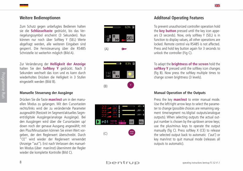
Zum Schutz gegen unbefugtes Bedienen haltensie die Schlüsseltaste gedrückt, bis das Ver -riegelungssymbol erscheint (3 Sekunden). Nunkönnen nur noch über Softkey Y (SEL) Werteabgefragt werden, alle weiteren Eingaben sindgesperrt. Die Fernsteuerung über die RS485Schnistelle ist weiterhin möglich (Bild A).
Zur Veränderung der Helligkeit der Anzeigehalten Sie den Softkey Y gedrückt. Nach 3Sekunden wechselt das Icon und es kann durchwiederholtes Drücken die Helligkeit in 3 Stufeneingestellt werden (Bild B).
Manuelle Steuerung der Ausgänge
Drücken Sie die Taste man/inst um in den manu-ellen Modus zu gelangen. Mit den Cursortastenrechts/links wird der zu verändernde Parameterausgewählt (Restzeit im Segment/aktuelles Segm-ent/digitale Ausgänge/analoge Ausgänge). Beiden Ausgängen wird über die Cursortasten up/down noch der genaue Ausgang angewählt; mitden Plus/Minustasten können Sie einen Wert vor-geben, der den Reglerwert überschreibt. Durch“CE” wird wieder der Reglerwert verwendet(Anzeige “aut”). Erst nach Verlassen des manuel-len Modus (über man/inst) übernimmt der Reglerwieder die komplette Kontrolle (Bild C).
Additonal Operating Features
To prevent unauthorized controller operation holdthe key button pressed until the key icon appe-ars (3 seconds). Now, only softkey Y (SEL) is infunction to display values, all other operations arelocked. Remote control via RS485 is not affected.Press and hold key button again for 3 seconds tounlock the controller (Fig C).
To adapt the brightness of the screen hold thesoftkey Y pressed until the softkey icon changes(fig B). Now press the softkey multiple times tochange screen brightness (3 levels).
Manual Operation of the Outputs
Press the key man/inst to enter manual mode.Use the left/right arrow keys to select the parame-ter to change (possible choices are remaining seg-ment time/segment no./digital outputs/analogueoutputs). When selecting outputs the actual out-put number is chosen by the up/down arrow keys;use the plus/minus keys to operate the outputmanually (fig C). Press softkey X (CE) to releasethe selected output back to automatic (‘aut’) orkey man/inst to quit manual mode (releases alloutputs to automatic).
(C)
(B)
(A)
9operating instructions bentrup TC-S2 V1.1
Message
s
Ereignis- und Fehlermeldungen
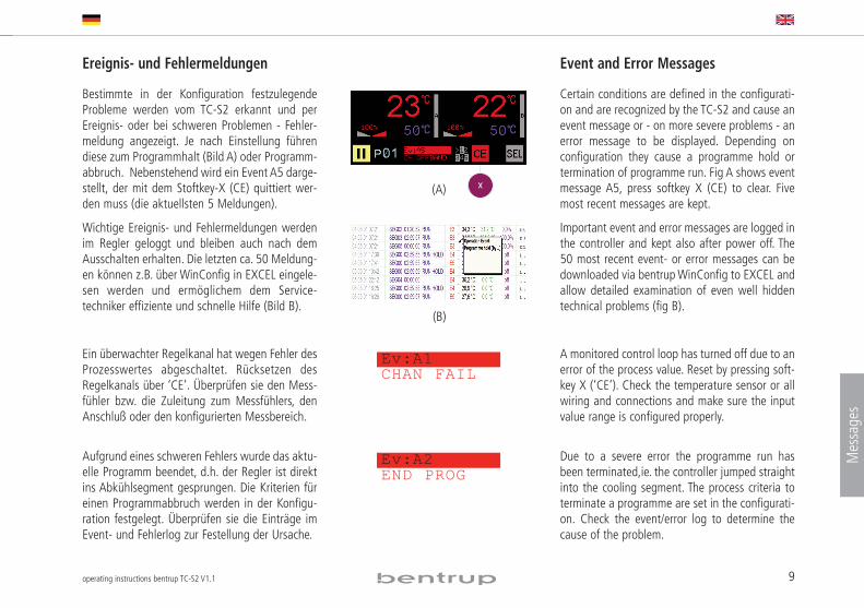
Bestimmte in der Konfiguration festzulegendeProbleme werden vom TC-S2 erkannt und perEreignis- oder bei schweren Problemen - Fehler -meldung angezeigt. Je nach Einstellung führendiese zum Programmhalt (Bild A) oder Programm -abbruch. Nebenstehend wird ein Event A5 darge-stellt, der mit dem Stoftkey-X (CE) quittiert wer-den muss (die aktuellsten 5 Meldungen).
Wichtige Ereignis- und Fehlermeldungen werdenim Regler geloggt und bleiben auch nach demAusschalten erhalten. Die letzten ca. 50 Meldung -en können z.B. über WinConfig in EXCEL eingele-sen werden und ermöglichem dem Service -techniker effiziente und schnelle Hilfe (Bild B).
Ein überwachter Regelkanal hat wegen Fehler desProzesswertes abgeschaltet. Rücksetzen desRegelkanals über ‘CE’. Überprüfen sie den Mess-fühler bzw. die Zuleitung zum Messfühlers, denAnschluß oder den konfigurierten Messbereich.
Aufgrund eines schweren Fehlers wurde das aktu-elle Programm beendet, d.h. der Regler ist direktins Abkühlsegment gesprungen. Die Kriterien füreinen Programmabbruch werden in der Konfigu -ration festgelegt. Überprüfen sie die Einträge imEvent- und Fehlerlog zur Festellung der Ursache.
Event and Error Messages
Certain conditions are defined in the configurati-on and are recognized by the TC-S2 and cause anevent message or - on more severe problems - anerror message to be displayed. Depen ding onconfiguration they cause a programme hold ortermination of programme run. Fig A shows eventmessage A5, press softkey X (CE) to clear. Fivemost recent messages are kept.
Important event and error messages are logged inthe controller and kept also after power off. The50 most recent event- or error messages can bedownloaded via bentrup WinConfig to EXCEL andallow detailed examination of even well hiddentechnical problems (fig B).
A monitored control loop has turned off due to anerror of the process value. Reset by pressing soft-key X (‘CE’). Check the temperature sensor or allwiring and connections and make sure the inputvalue range is configured properly.
Due to a severe error the programme run hasbeen terminated,ie. the controller jumped straightinto the cooling segment. The process criteria toterminate a programme are set in the configurati-on. Check the event/error log to determine thecause of the problem.
(A)
(B)
Ev:A1CHAN FAIL
Ev:A2END PROG
10 operating instructions bentrup TC-S2 V1.1
Messages
Im Master / Slave Betriebsmodus hat ein Slave-Regler einschweres Problem gemeldet. Details sind am Slave zuerkennen und zu beheben.
Ein überwachter Regelkanal hat Gradientenfehler gemel-det (zu geringes Aufheizen trotz maximaler Heizleistungoder Problem durch Betriebseingriff). Diese Meldungweist eindeutig auf ein Problem am Ofen hin! Überprü-fen sie Heizspiralen, Netzphasen, alle Schützkontakteauch nach längerem Betrieb. Stellen sicher, dass dasThermo element korrekt der Tempeartur ausgesetzt istund die Zuleitung nicht kurzgeschlossen ist.
Wenn die Temperatur nicht dem vom Progamm vorgege-benen Anstieg folgt, geht der Regler in HOLD und zeigtdiese Meldung an. Hiedurch wird dem System Zeit gege-ben, die Temperatur aufzuholen. Sowohl die Kriterien alsauch das Verhalten des Reglers, falls die Temperatur nichtinnerhalb einer einstellbaren Zeit aufgeholt wird, werdenin der Konfiguration festgelegt. Hinweis fürMehrzonensysteme: Physikalisch bedingt können dieTemperaturen aller Zonen nur ausgeglichen werden,wenn alle Kanäle im Regel bereich sind. Hierfür ist dieseFunktion besonders hilfreich.
Nach einem Ev A5 hat das System erfolgreich Tem -peratur aufgeholt, daher wurde der Pro gramm lauf fort-gesetzt. Diese Meldung wird zur Information für eineMinute angezeigt.
During master / slave operation a slave controller hasreported a severe problem. Check the slave controller toidentify and solve the cause.
A monitored control loop has reported a gradient error(temperature increasing too slow despite full power hea-ting or kiln interrupted). This error message points clear-ly to a kiln problem! Carefully check heating elements,mains supply/lines, contactor (also when warm). Makesure the thermocouple is exposed properly to the tempe-rature and the thermocouple leads are not short circuited.
If the temperature does not follow the programmed ratethe controller enters HOLD state and shows this eventmessage. This gives the system time to catch up with thetemperature. The criteria for holding, as well as the reac-tion if the situation is not solved during hold, can bedeterminend by the configuration. Note for multi zonecontrollers: The temperature in the different zones canonly be equalized if all zones are within control range.The holding feature is to ensure this physical limitationcan be observed as long as possible.
After entering Ev A5 holding the system has successfullycaugth up with the temperature, therefore programmerun has been continued. This message is displayed forone minute.
Ev:A3ERR SLAVE
Ev:A4CHAN GRAD
Ev:A5CH OFFBAND
Ev:A6CHAN CONT

11operating instructions bentrup TC-S2 V1.1
Message
s
Nach einem Ev A5 hat das System den Tempe ratur-rückstand nicht aufgeholt, darauf wurde der Pro -gramm lauf gemäß Konfiguration abgebrochen.
Nach einem Ev A5 hat das System den Tempera tur -rückstand nicht aufgeholt, gemäß Konfiguration wurdeder Programmlauf trotzdem fortgesetzt. DieseMeldung wird für eine Minute angezeigt.
Ein Segment wird erst normaler Weise erst beendet,wenn die Temperatur aller überwachten Zonen denEndwert erreicht hat. Um ein Hängen bleiben zu ver-meiden überprüft der Regler, ob die Temperaturen sichnoch annähern, andernfalls beendet der Regler dasSegment trotzdem (‘Emergency Exit’)
Reglerneustart trotz ausreichender Versorgungs -spannung. Prüfen Sie korrekte Erdung und externeStörsignale.
Nach Wiederkehr der Netzspannung wurde derProgrammlauf automatisch forgesetzt. Kriterien wer-den in der Konfiguration eingestellt.
Trotz Wiederkehr der Netzspannung wurde dasProgramm nicht fortgesetzt, weil 1=durch Kon fi gu -ration verboten, 2=DO war inaktiv, 3=Maxi malzeitüberschritten, 4=Temperaturabfall zu groß
After entering Ev A5 holding the system failed tocatch up the temperature, therefore programme runhas been terminated according to the configuration.
After entering Ev A5 holding the system failed tocatch up the temperature, however, as requested byconfiguration the programme is continued. This mes-sage is displayed for one minute.
Usually a segment is terminated if the temperatu-re of all monitored zones matches the final value.However, to avoid a deadlock the controller entersnext segment if it finds zone temperatures are notapproaching any more (‘Emergency Exit’).
Controller restart although power supply is good.Check proper grounding of the controller andverify no noisy electrical environment.
Programme is continued automatically afterpower failure. Criteria are to be set in the configu-ration.
After power was reestablished the program is notcontinued due to 1=disabled by configuration2=DO not active, 3=maximum period expired,4=Temperature dropped too much
Ev:A7CHAN BREAK
Ev:A8CHAN OB/C
Ev:A9CHAN EM/E
Ev:B1PWG CONT
Ev:B2PWF CONT
Ev:B3.xPWF BREAK
12 operating instructions bentrup TC-S2 V1.1
Messages
Autotune kann nicht durchgeführt werden, weil der konfi-gurierte Regelalgorithmus hierfür ungeeignet ist.
Autotune (Selbstoptimierungszyklus) aktiv. Details sieheKapitel weiter hinten in dieser Anleitung
Autotune wurde abgebrochen, weil während des Vorgangsein Regelkanal in Fehlerzustand gegangen ist. Hierdurch istkein aussagekräftiges Ergebnis möglich.
Autotune wurde zu Ende geführt, die ermittelten Parameterwurden nach Evaluierung jedoch als nicht geeignet befun-den. Sicherheitsfeature zur Vermeidung von Fehlfunktion.
Autotune wurde erfolreich zu Ende geführt und die ermit-telten Parameter für aussagekräftig bewertet und in dieKonfiguration geschrieben.
Internes technisches Problem: Mess-Signalverstärkerdefekt. Wenden sie sich an den Kundendienst.
Internes technisches Problem: Mess-Signalverstärker unge-nau. Wenden sie sich an den Kundendienst.
Die Ein/Ausgabeeinheit in Slot Nr. # hat ein Problem gemel-det. Überprüfen Sie den korrekten Sitz und Installation.
Die interne PLC (optionales, sehr leistungsfähiges Feature)hat ein Problem gemeldet. Verbinden sie den Regler zurDiagnose mit der bentrup PLC-download-Utility.
Hardwareproblem des Reglers, konsultieren sie denKundendienst (# steht für 1=CPU, 2=RAM, 3=I2C Bus,4=I2C Device, 5=Kalibrierungsdaten Prüfsummenfehler)
Unable to perform autotune since the configured controlalgorithm is not suitable (must be PID / C-PID)
Autotune self optimization in progress. For details see chap-ter further on in this booklet
Autotune was cancelled due to one control loop enterederror state. All control must work properly to get a reasona-ble result.
Autotune was completed but the calculated parameterswere evaluated as unsuitable. This safety relevant featureavoids bad control results on strange parameters.
Autotune was completed successfully, the results are consi-dered valid and the new PID parameters were saved to theconfiguration.
Internal technical problem. Signal converter broken. Servicerequired.
Internel technical probelm. Signal converter self validationfailed. Service required.
The Input/Output extension in slot no. # failed. Check pro-per installation and possible IO board error indicator.
Integrated PLC (a very smart and powerful feature) repor-ted a problem. Use the bentrup PLC download utility tofurther diagnose the cause of the problem.
controller hardware problem, service required (# stands for1=CPU, 2=RAM, 3=I2C bus, 4=I2C device, 5=calibrationdata checksum error)
Ev:B5AT BADPEv:B6AUTOTUNEEv:B7AT FAILED
Ev:B8AT INV RUN
Ev:B9AT SUCCESS
Ev:C1AD FAILEv:C2AD INACCUREv:C3.#IO EXP ERREv:C5PLC ERROR
Ev:D#PLC ERROR
13operating instructions bentrup TC-S2 V1.1
Autotune
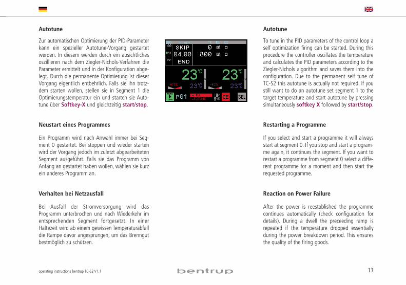
Zur automatischen Optimierung der PID-Parameterkann ein spezieller Autotune-Vorgang gestartetwerden. In diesem werden durch ein absichtlichesoszillieren nach dem Ziegler-Nichols-Verfahren dieParameter ermittelt und in der Konfiguration abge-legt. Durch die permanente Optimierung ist dieserVorgang eigentlich entbehrlich. Falls sie ihn trotz-dem starten wollen, stellen sie in Segment 1 dieOptimierungstemperatur ein und starten sie Auto -tune über Softkey-X und gleichzeitig start/stop.
Neustart eines Programmes
Ein Programm wird nach Anwahl immer bei Seg -ment 0 gestartet. Bei stoppen und wieder startenwird der Vorgang jedoch im zuletzt abgearbeitetenSegment ausgeführt. Falls sie das Programm vonAnfang an gestartet haben wollen, wählen sie kurzein anderes Programm an.
Verhalten bei Netzausfall
Bei Ausfall der Stromversorgung wird dasProgramm unterbrochen und nach Wiederkehr imentsprechenden Segment fortgesetzt. In einerHaltezeit wird ab einem gewissen Temperaturabfalldie Rampe davor angesprungen, um das Brenngutbestmöglich zu schützen.
Autotune
To tune in the PID parameters of the control loop aself optimization firing can be started. During thisprocedure the controller oscillates the temperatureand calculates the PID parameters according to theZiegler-Nichols algorithm and saves them into theconfiguration. Due to the permanent self tune ofTC-S2 this autotune is actually not required. If youstill want to do an autotune set segment 1 to thetarget temperature and start autotune by pressingsimultaneously softkey X followed by start/stop.
Restarting a Programme
If you select and start a programme it will alwaysstart at segment 0. If you stop and start a program-me again, it continues the segment. If you want torestart a programme from segment 0 select a diffe-rent programme for a moment and then start therequested programme.
Reaction on Power Failure
After the power is reestablished the programmecontinues automatically (check configuration fordetails). During a dwell the preceeding ramp isrepeated if the temperature dropped essentiallyduring the power breakdown period. This ensuresthe quality of the firing goods.

14 operating instructions bentrup TC-S2 V1.1
15operating instructions bentrup TC-S2 V1.1
Mechn
ical
Electrical
Configuration
TTeecchhnniiccaall MMaannuuaall (english only)
Mechanical Installation
Electrical Installation
Configuration
Programme Controller TTCC SS22
16 operating instructions bentrup TC-S2 V1.1
Mechanical
Mechanical Installation
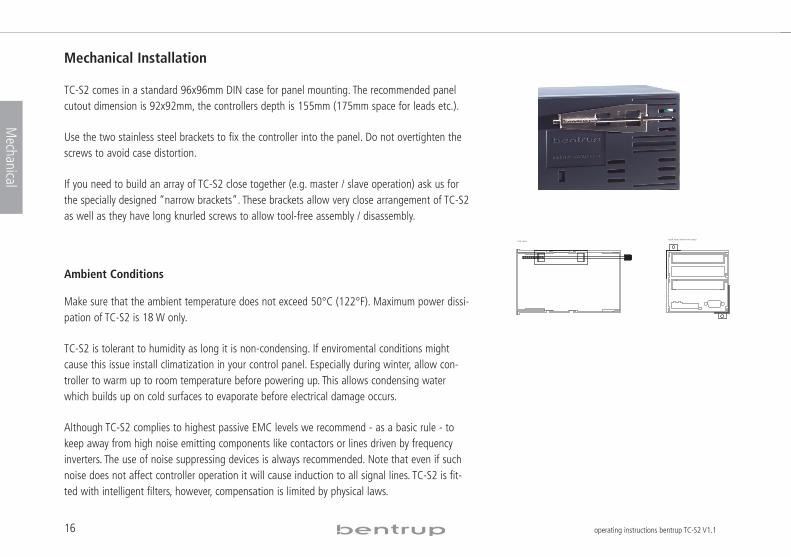
TC-S2 comes in a standard 96x96mm DIN case for panel mounting. The recommended panelcutout dimension is 92x92mm, the controllers depth is 155mm (175mm space for leads etc.).
Use the two stainless steel brackets to fix the controller into the panel. Do not overtighten thescrews to avoid case distortion.
If you need to build an array of TC-S2 close together (e.g. master / slave operation) ask us forthe specially designed “narrow brackets”. These brackets allow very close arrangement of TC-S2as well as they have long knurled screws to allow tool-free assembly / disassembly.
Ambient Conditions
Make sure that the ambient temperature does not exceed 50°C (122°F). Maximum power dissi-pation of TC-S2 is 18 W only.
TC-S2 is tolerant to humidity as long it is non-condensing. If enviromental conditions mightcause this issue install climatization in your control panel. Especially during winter, allow con-troller to warm up to room temperature before powering up. This allows condensing waterwhich builds up on cold surfaces to evaporate before electrical damage occurs.
Although TC-S2 complies to highest passive EMC levels we recommend - as a basic rule - tokeep away from high noise emitting components like contactors or lines driven by frequencyinverters. The use of noise suppressing devices is always recommended. Note that even if suchnoise does not affect controller operation it will cause induction to all signal lines. TC-S2 is fit-ted with intelligent filters, however, compensation is limited by physical laws.
back view (shown w/o axis)
top viewside view
Notches to lock caselike on prev. brackets
back view (shown w/o axis)
top viewside view
Notches to lock caselike on prev. brackets
17operating instructions bentrup TC-S2 V1.1
Electrical
Electrical Installation
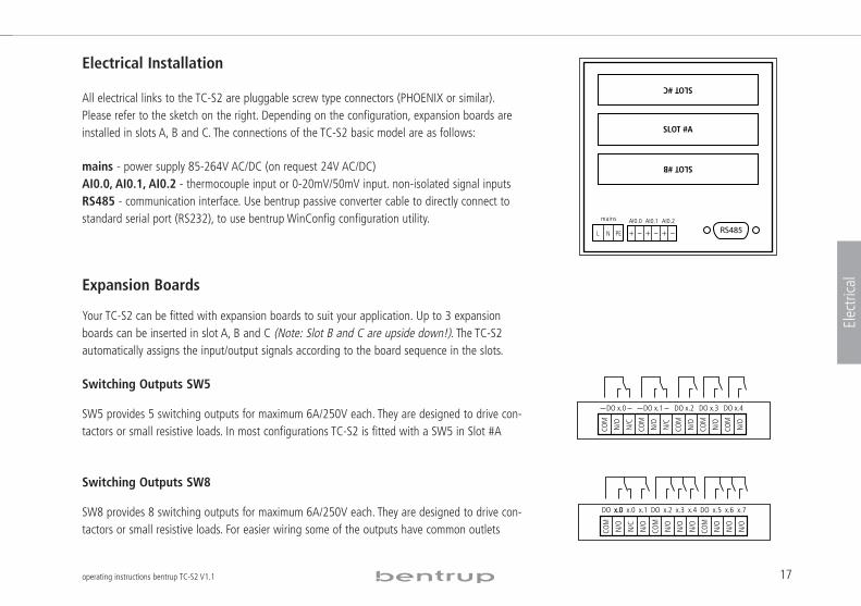
All electrical links to the TC-S2 are pluggable screw type connectors (PHOENIX or similar).Please refer to the sketch on the right. Depending on the configuration, expansion boards areinstalled in slots A, B and C. The connections of the TC-S2 basic model are as follows:
mains - power supply 85-264V AC/DC (on request 24V AC/DC)AI0.0, AI0.1, AI0.2 - thermocouple input or 0-20mV/50mV input. non-isolated signal inputsRS485 - communication interface. Use bentrup passive converter cable to directly connect tostandard serial port (RS232), to use bentrup WinConfig configuration utility.
Expansion Boards
Your TC-S2 can be fitted with expansion boards to suit your application. Up to 3 expansionboards can be inserted in slot A, B and C (Note: Slot B and C are upside down!). The TC-S2automatically assigns the input/output signals according to the board sequence in the slots.
Switching Outputs SW5
SW5 provides 5 switching outputs for maximum 6A/250V each. They are designed to drive con-tactors or small resistive loads. In most configurations TC-S2 is fitted with a SW5 in Slot #A
Switching Outputs SW8
SW8 provides 8 switching outputs for maximum 6A/250V each. They are designed to drive con-tactors or small resistive loads. For easier wiring some of the outputs have common outlets
RS485
SLOT #A
SLOT #C
SLOT #B
11,84 mm
AI0.1 AI0.2AI0.0
L N PE
mains
COM
DO x.0
COM
N/O
COM
N/O
COM
N/C
N/ON/C
N/O
N/O
COM
DO x.1 DO x.2 DO x.4DO x.3
COM
x.0x.0 x.7x.6x.5x.4x.3x.2x.1x.0
N/O
N/O
COM
N/O
N/O
N/O
COM
N/C
N/O
N/O
N/O
DODO DO
18 operating instructions bentrup TC-S2 V1.1
Electrical
Analogue Inputs AI4
AI4 provides 4 electrical isolated high accuracy inputs for generic use. Input signal type is forthermocouples, PT100, 0-20mV/50mV, 0-5V, 0-10V, 0/4-20mA, resistive types (2 or 3 wire).Selection is done by the configuration automatically.
See sketch on the right for individual signal connections.
Analogue Outputs AO4
AO4 module expands your TC-S2 with 4 electrically isolated outputs to drive power devices(such as thyristors) or to output process values.. Depending on configuration the output provi-des a 0-10V or 0/4-20mA signal. In voltage mode the max load is limited to 50mA each output,in current mode a burdon <600 Ohms is required. Overload or open output failure is detectedand reported. An AUTO-restart takes place every 2 seconds (output LED on AO4 flashes).
Digital Inputs / Outputs DIO8
DIO8 provides 8 digital inputs and outputs each. The outputs are designed to directly drive DCrelays (max. load 1A per output). The outputs are short circuit proof and contain thermal protec-tion. Overload condition is reported to the TC-S2. The inputs directly connect to any actuatorsensor (input current threshold 5mA). Both inputs and outputs are optically isolated from theTC-S2 and designed for 24V DC operation (voltage GOOD is reported to the TC-S2). However,the actual operating range is from 10 to 30V DC.
AIx.0
COM
+
U -
I -
R -
AIx.3
COM
+
U -
I -
R -
AIx.2
COM
+
U -
I -
R -
AIx.1
COM
+
U -
I -
R -
+
Voltage Signals
COM+
U -
I -R -
COM+
U -
I -R -
+
Current Signals
COM+
U -
I -R -
Resistance Signals
(3-wire)Thermocouple
AOx.0 AOx.3AOx.2AOx.1
+ +++
x.1 x.6x.5x.4x.3x.2
OUT
OUT
VCC
x.7
OUT
OUT
OUT
OUT
OUT
x.0
OUT
x.4x.3x.2x.1x.0
IN IN
x.6
IN
x.5
ININININGN
D
x.7
IN
+
19operating instructions bentrup TC-S2 V1.1
Electrical
Combined IO ‘COMBI a’
‘COMBI a’ provides 4 PWM outputs, 3 switching outputs 6A / 250V and 3 analogue inputswhich can be used for either additional thermocouple inputs or for 3-wire inputs together withmainboard inputs. PWM outputs are desgined to drive solid state relays (SSR) at adjustablespeed (1/2/5/10 Hz). The outputs are activated one after the other for best mains load patternand provide a short circuit protection with auto restart. An overload is indicated on the TC-S2.
Combined IO ‘COMBI b’
‘COMBI b’ is the same as ‘COMBI a‘ but has 3 digital inputs instead of the analogue inputs.
Combined IO ‘COMBI c’
‘COMBI c’ provides 3 switching outputs 6A / 250V, SYSBUS and 3 digital inputs. SYSBUS is usedto chain multiple TC-S2 for master slave operation which is similar to multizone operation withone TC-S2, but provides extended graphical illusion of the chain as well as the option to splitthe chain into several sub chains simply by the operator. It also provides electrical isolation ofthe inputs. Typical application are heat treatment systems for welding. Daisy chain the OUT tothe IN signal of the following TC-S2 and the OUT of the last in chain to the first (Bus-Master).
Assignement of the input and output ports
Depending on the expansion boards fitted the input and output designators (e.g. DO1.0) areassigned automatically only depending on the sequence of each type in the slot. Example: SLOTA holds SW5 (becomes DO0.0 to 5), SLOT B an AI4 (becomes AI2.0-3 since AI0.x and AI1.x areon mainboard) and SLOT C a SW8 (becomes DO1.0 to 7). Press ‘Y’ during power up to displaycurrent assignment and other relevant internal information (refer to the sketch).
x.1 x.3x.2
PWM
PWM
PWM
PWM
GN
D
x.0
GN
D
x.2x.1x.0
N/O
COM
N/O
N/O
DO AI0.4 AI0.5AI0.3
x.1 x.3x.2
PWM
PWM
PWM
PWM
GN
D
x.0
GN
D
x.2x.1x.0
N/O
COM
N/O
N/O
DO x.2x.1x.0
IN ININ
x.2x.1x.0
N/O
COM
N/O
N/O
DO x.2x.1x.0
IN ININ
OUT SYSBUS IN
RX+
RX-
RGND
TGNDTX-
TX+
N/C
COM
DO
20 operating instructions bentrup TC-S2 V1.1
Configuration
Configuration
The configuration defines the entire TC-S2 structure. TC-S2 is more a highly flexible computerfor control applications than an ordinary controller. As a consequence, even minor changesmight affect the basic controller operation. Your system builder will have preconfigured the TC-S2 according to your application so normally it is not required to enter configuration. Get your-self familiar with the meaning of the parameters before you start adjusting the configuration.See next page for a detailed explanation of all TC-S2 parameters.
Configuration via keypad
All configuration parameters can be changed by the keypad. Enter the configuration by hol-ding the ‘inst’ key pressed for 3 seconds. Now you can navigate through the parameters usingthe cursor keys and modify if necessary. Use the keys ‘X’ res. ‘Y’ to directly change between theconfiguration tables. Press and hold key ‘inst’ again to save and leave configuration.
Note: If TC-S2 re-enters configuration automatically it has detected an illegal setting (ie. aninput mode which is not available physically or a servomotor indication on a switching output).
Configuration and Reading Controller Logs via PC software
Download the free of charge configuration utility “WinConfig” from www.bentrup.com. Thisutility allows easy setting, saving and restoring configuration. Use WinConfig to download thecontrollers error log which - like a flight recorder - contains all relevant process values of thelast 50 controller events (even after power down). The offline created data log of TC-S2 can bealso downloaded. All data shown is easily understood in Microsoft EXCEL.
TC-S2 with Integrated PLC (Option)
Configuration allows even complex input output control including logical functions; if yourapplications require even more complex networks (including timers etc.) check out the corre-sponding application note on www.bentrup.com.
21operating instructions bentrup TC-S2 V1.1
Configuration
bentrup TC!S2 Configuration Table Version 7.40
Table 0: clock / calender
The controller uses its real time clock / calender for different purposes. It allows the automatic commencing of programmes at predefined times as well the real time clock / calender is used to time stamp logged data and events. When configuring the controller using bentrup WinConfig / WinControl the controller is automatically updated with the PCs time / date information, Therefore manually changeing time / date is disabled . 00: time (hours) (value range 00 to 23)
current time (hours) of the real time clock
01: time (minutes) (value range 00 to 59)
current time (minutes) of the real time clock
02: DST auto adj. (value range ADJ OFF to USA/CAN)
Selects daylight saving time algorithm
03: date (day) (value range 01 to 31)
current date (day) of the real time calendar
04: date (month) (options JAN, FEB, MAR, APR, MAY, JUN, JUL, AUG, SEP, OCT, NOV, DEC)
current date (month) of the real time calendar
05: date (year) (value range 00 to 99)
current date (year) of the real time calendar
06: cfg.lock level (value range 0 to 5)
reserved for future used
.
Table 1: misc. adjustments
The following miscalleneous adjustments determine general operation parameters of the controller .
00: max. segments (value range 5 to 98)
maximum number of segments per programme. Entering a smaller number increases the number of programmes you can save in your controller. In most applications a maximum of 20 segments is suitable. Note: After changing this value all programmes must be reentered because of the required reorganisation of the controllers memory
01: log rate (sec) (value range 0 to 120)
All important process values will be sampled to the controllers log memory for further examination by the operator. Since the log memory is quite limited adjust the log rate to the highest value suitable for your application. The log rate (specified in seconds) determines the time between two recordings. The actual size of the log memory depends on the configuration
02: manual enable (options OFF, ON)
The manual mode allows the user to individually operate the control outputs (digital outputs and analog outputs) manually. This feature is very helpful for kiln commissioning. Caution: For safety reasons only enable this MODE if the operator is familiar with it !
03: auto P. starts (options OFF, ON)
This feature allows automatic commencing programmes by the weekly switching clock. Depending on configuration up to 99 real time clock / weekdays controlled jobs can be entered. Enable this feature only if necessary to avoid unintentional programme commencing
04: lock programs (options OFF, ON)
Allows locking of all programmes (temperature curves) to avoid any unauthorized changes
05: communicat. ID (value range OFF to 62)
22 operating instructions bentrup TC-S2 V1.1
Configuration
Sets the communication ID of the controller. Affects external communication only. Make sure that this ID fits the setting in the communcation software (e.g. bentrup WinControl). Each ID must be unique on the communication network
06: Slaves in Chain (value range 0 to 15)
no explanation available
07: fctn.on pow.up (value range 0 to 3)
Verhalten nach dem Einschalten: 0=Regler aus (IDLE), 1/2=automatischer Programmstart wenn alle Bedingungen erfüllt sind (1=Zeit!Limit in Sekunden / 2=Zeit!Limit in Minuten). 3=automatischer Programmstart
08: ..only if DOxx (value range OFF, DO0.0 to DO2.3)
Programme is continued only if the selected output was ON before power breakdown. When selecting and output controlled by a programme EVENT, this feature can be used to enable programme continuation after a power breakdown for each segment
09: only if t<time (value range OFF to 240)
Programme is continued only if the duration of the power failure was less than this parameter. Depending on the selection of "fctn. on pow. up" this time limit is seconds or minutes
10: dT input sel (value range OFF, IN00 to IN19)
Selects the process value check for drop in temperature during a power breakdown
11: ..only if dT<x (value range !9999 to 9999)
Programme is continued only if the selected process value did not drop more than a the given value during power breakdown
12: p.time MIN:SEC (options OFF, ON)
Set to 1 for fast programme cycles to enter segment time as minutes : seconds (MIN:SEC) instead of hours : minutes
Table 2: analog input
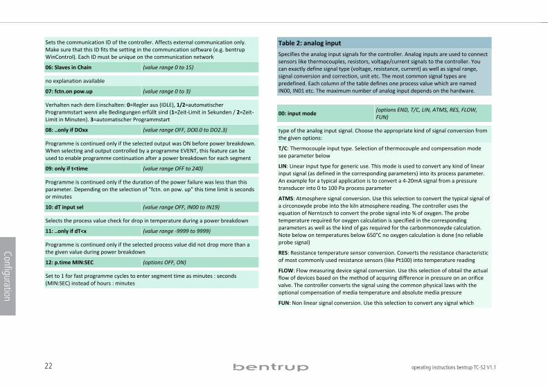
Specifies the analog input signals for the controller. Analog inputs are used to connect sensors like thermocouples, resistors, voltage/current signals to the controller. You can exactly define signal type (voltage, resistance, current) as well as signal range, signal conversion and correction, unit etc. The most common signal types are predefined. Each column of the table defines one process value which are named IN00, IN01 etc. The maximum number of analog input depends on the hardware. .
00: input mode (options END, T/C, LIN, ATMS, RES, FLOW, FUN)
type of the analog input signal. Choose the appropriate kind of signal conversion from the given options:
T/C: Thermocouple input type. Selection of thermocouple and compensation mode see parameter below
LIN: Linear input type for generic use. This mode is used to convert any kind of linear input signal (as defined in the corresponding parameters) into its process parameter. An example for a typical application is to convert a 4!20mA signal from a pressure transducer into 0 to 100 Pa process parameter
ATMS: Atmosphere signal conversion. Use this selection to convert the typical signal of a circonoxyde probe into the kiln atmosphere reading. The controller uses the equation of Nerntzsch to convert the probe signal into % of oxygen. The probe temperature required for oxygen calculation is specified in the corresponding parameters as well as the kind of gas required for the carbonmonoxyde calculation. Note below on temperatures below 650°C no oxygen calculation is done (no reliable probe signal)
RES: Resistance temperature sensor conversion. Converts the resistance characteristic of most commonly used resistance sensors (like Pt100) into temperature reading
FLOW: Flow measuring device signal conversion. Use this selection of obtail the actual flow of devices based on the method of acquring difference in pressure on an orifice valve. The controller converts the signal using the common physical laws with the optional compensation of media temperature and absolute media pressure
FUN: Non linear signal conversion. Use this selection to convert any signal which
23operating instructions bentrup TC-S2 V1.1
Configuration
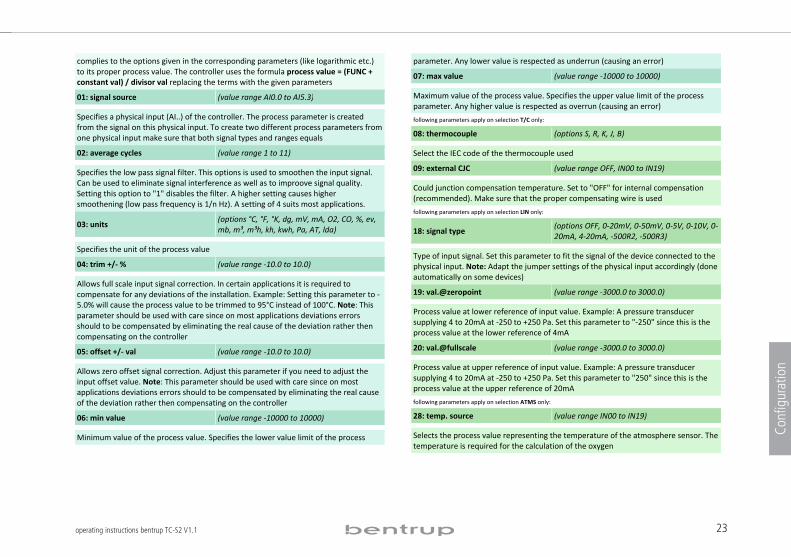
complies to the options given in the corresponding parameters (like logarithmic etc.) to its proper process value. The controller uses the formula process value = (FUNC + constant val) / divisor val replacing the terms with the given parameters
01: signal source (value range AI0.0 to AI5.3)
Specifies a physical input (AI..) of the controller. The process parameter is created from the signal on this physical input. To create two different process parameters from one physical input make sure that both signal types and ranges equals
02: average cycles (value range 1 to 11)
Specifies the low pass signal filter. This options is used to smoothen the input signal. Can be used to eliminate signal interference as well as to improove signal quality. Setting this option to "1" disables the filter. A higher setting causes higher smoothening (low pass frequency is 1/n Hz). A setting of 4 suits most applications.
03: units (options °C, °F, °K, dg, mV, mA, O2, CO, %, ev, mb, m³, m³h, kh, kwh, Pa, AT, lda)
Specifies the unit of the process value
04: trim +/! % (value range !10.0 to 10.0)
Allows full scale input signal correction. In certain applications it is required to compensate for any deviations of the installation. Example: Setting this parameter to !5.0% will cause the process value to be trimmed to 95°C instead of 100°C. Note: This parameter should be used with care since on most applications deviations errors should to be compensated by eliminating the real cause of the deviation rather then compensating on the controller
05: offset +/! val (value range !10.0 to 10.0)
Allows zero offset signal correction. Adjust this parameter if you need to adjust the input offset value. Note: This parameter should be used with care since on most applications deviations errors should to be compensated by eliminating the real cause of the deviation rather then compensating on the controller
06: min value (value range !10000 to 10000)
Minimum value of the process value. Specifies the lower value limit of the process
parameter. Any lower value is respected as underrun (causing an error)
07: max value (value range !10000 to 10000)
Maximum value of the process value. Specifies the upper value limit of the process parameter. Any higher value is respected as overrun (causing an error)
following parameters apply on selection T/C only:
08: thermocouple (options S, R, K, J, B)
Select the IEC code of the thermocouple used
09: external CJC (value range OFF, IN00 to IN19)
Could junction compensation temperature. Set to "OFF" for internal compensation (recommended). Make sure that the proper compensating wire is used
following parameters apply on selection LIN only:
18: signal type (options OFF, 0!20mV, 0!50mV, 0!5V, 0!10V, 0!20mA, 4!20mA, !500R2, !500R3)
Type of input signal. Set this parameter to fit the signal of the device connected to the physical input. Note: Adapt the jumper settings of the physical input accordingly (done automatically on some devices)
19: val.@zeropoint (value range !3000.0 to 3000.0)
Process value at lower reference of input value. Example: A pressure transducer supplying 4 to 20mA at !250 to +250 Pa. Set this parameter to "!250" since this is the process value at the lower reference of 4mA
20: val.@fullscale (value range !3000.0 to 3000.0)
Process value at upper reference of input value. Example: A pressure transducer supplying 4 to 20mA at !250 to +250 Pa. Set this parameter to "250" since this is the process value at the upper reference of 20mA
following parameters apply on selection ATMS only:
28: temp. source (value range IN00 to IN19)
Selects the process value representing the temperature of the atmosphere sensor. The temperature is required for the calculation of the oxygen
24 operating instructions bentrup TC-S2 V1.1
Configuration
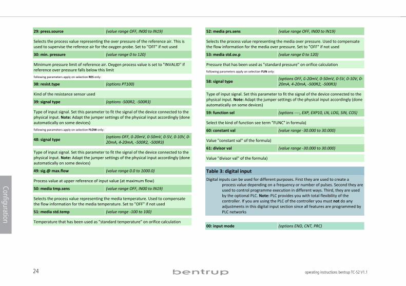
29: press.source (value range OFF, IN00 to IN19)
Selects the process value representing the over pressure of the reference air. This is used to supervise the referece air for the oxygen probe. Set to "OFF" if not used
30: min. pressure (value range 0 to 120)
Minimum pressure limit of reference air. Oxygen process value is set to "INVALID" if reference over pressure falls below this limit following parameters apply on selection RES only: 38: resist.type (options PT100)
Kind of the resistance sensor used
39: signal type (options !500R2, !500R3)
Type of input signal. Set this parameter to fit the signal of the device connected to the physical input. Note: Adapt the jumper settings of the physical input accordingly (done automatically on some devices)
following parameters apply on selection FLOW only:
48: signal type (options OFF, 0!20mV, 0!50mV, 0!5V, 0!10V, 0!20mA, 4!20mA, !500R2, !500R3)
Type of input signal. Set this parameter to fit the signal of the device connected to the physical input. Note: Adapt the jumper settings of the physical input accordingly (done automatically on some devices)
49: sig.@ max.flow (value range 0.0 to 1000.0)
Process value at upper reference of input value (at maximum flow)
50: media tmp.sens (value range OFF, IN00 to IN19)
Selects the process value representing the media temperature. Used to compensate the flow information for the media temperature. Set to "OFF" if not used
51: media std.temp (value range !100 to 100)
Temperature that has been used as "standard temperature" on orifice calculation
52: media prs.sens (value range OFF, IN00 to IN19)
Selects the process value representing the media over pressure. Used to compensate the flow information for the media over pressure. Set to "OFF" if not used
53: media std.ov.p (value range 0 to 120)
Pressure that has been used as "standard pressure" on orifice calculation
following parameters apply on selection FUN only:
58: signal type (options OFF, 0!20mV, 0!50mV, 0!5V, 0!10V, 0!20mA, 4!20mA, !500R2, !500R3)
Type of input signal. Set this parameter to fit the signal of the device connected to the physical input. Note: Adapt the jumper settings of the physical input accordingly (done automatically on some devices)
59: function sel (options !!!!, EXP, EXP10, LN, LOG, SIN, COS)
Select the kind of function see term "FUNC" in formula)
60: constant val (value range !30.000 to 30.000)
Value "constant val" of the formula)
61: divisor val (value range !30.000 to 30.000)
Value "divisor val" of the formula)
Table 3: digital input
Digital inputs can be used for different purposes. First they are used to create a process value depending on a frequency or number of pulses. Second they are used to control programme execution in different ways. Third, they are used by the optional PLC. Note: PLC provides you with total flexibility of the controller. If you are using the PLC of the controller you must not do any adjustments in this digital input section since all features are programmed by PLC networks
.
00: input mode (options END, CNT, PRC)
25operating instructions bentrup TC-S2 V1.1
Configuration
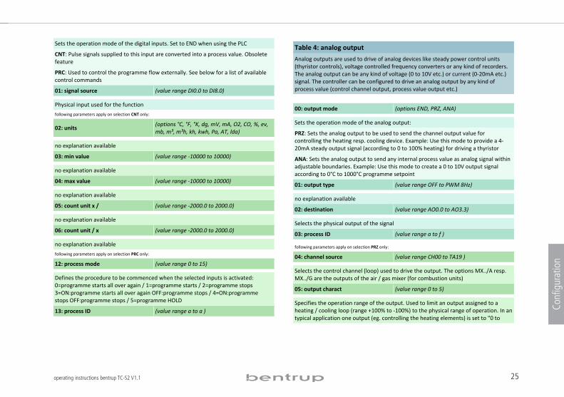
Sets the operation mode of the digital inputs. Set to END when using the PLC
CNT: Pulse signals supplied to this input are converted into a process value. Obsolete feature
PRC: Used to control the programme flow externally. See below for a list of available control commands
01: signal source (value range DI0.0 to DI8.0)
Physical input used for the function following parameters apply on selection CNT only:
02: units (options °C, °F, °K, dg, mV, mA, O2, CO, %, ev, mb, m³, m³h, kh, kwh, Pa, AT, lda)
no explanation available
03: min value (value range !10000 to 10000)
no explanation available
04: max value (value range !10000 to 10000)
no explanation available
05: count unit x / (value range !2000.0 to 2000.0)
no explanation available
06: count unit / x (value range !2000.0 to 2000.0)
no explanation available
following parameters apply on selection PRC only: 12: process mode (value range 0 to 15)
Defines the procedure to be commenced when the selected inputs is activated: 0=programme starts all over again / 1=programme starts / 2=programme stops 3=ON:programme starts all over again OFF:programme stops / 4=ON:programme stops OFF:programme stops / 5=programme HOLD
13: process ID (value range a to a )
Table 4: analog output
Analog outputs are used to drive of analog devices like steady power control units (thyristor controls), voltage controlled frequency converters or any kind of recorders. The analog output can be any kind of voltage (0 to 10V etc.) or current (0!20mA etc.) signal. The controller can be configured to drive an analog output by any kind of process value (control channel output, process value output etc.)
.
00: output mode (options END, PRZ, ANA)
Sets the operation mode of the analog output:
PRZ: Sets the analog output to be used to send the channel output value for controlling the heating resp. cooling device. Example: Use this mode to provide a 4!20mA steady output signal (according to 0 to 100% heating) for driving a thyristor
ANA: Sets the analog output to send any internal process value as analog signal within adjustable boundaries. Example: Use this mode to create a 0 to 10V output signal according to 0°C to 1000°C programme setpoint
01: output type (value range OFF to PWM 8Hz)
no explanation available
02: destination (value range AO0.0 to AO3.3)
Selects the physical output of the signal
03: process ID (value range a to f )
following parameters apply on selection PRZ only:
04: channel source (value range CH00 to TA19 )
Selects the control channel (loop) used to drive the output. The options MX../A resp. MX../G are the outputs of the air / gas mixer (for combustion units)
05: output charact (value range 0 to 5)
Specifies the operation range of the output. Used to limit an output assigned to a heating / cooling loop (range +100% to !100%) to the physical range of operation. In an typical application one output (eg. controlling the heating elements) is set to "0 to
26 operating instructions bentrup TC-S2 V1.1
Configuration
+100%" and a 2nd output (eg. controlling a fan) is set to "0 to !100%" (both outputs assigned to the same control channel). The available settings are 0=0% to +100% / 1=+100% to 0% / 2=0% to !100% / 3=!100% to 0% / 4=!100% to +100% / 5=+100% to !100%. The further settings will repeat the choices but use the motor characteristic for non!linear devices: 6 to 11: motor char.#0 / 12 to 17: motor char.#1 18 to 23: motor char#3 etc.
06: outp.% on IDLE (value range 0 to 100)
Whenever the controller is IDLE the output is fixed to this value
07: outp. % on ERR (value range 0 to 100)
Whenever the entire controller is in ERROR status the output is fixed to this value. Note that this only applies on system errors and not an operation error on a single channel
08: min. output % (value range 0 to 100)
Lower output signal limit. The output will never drop below this limit. Can be used for instance to obtain permanent minimum heating. Care should be taken since high settings might interfere with the control loop
09: max. output % (value range 0 to 100)
Upper output signal limit. The output will never exceed this limit. Can be used for instance to limit the maximum heating of a kiln. Note that limiting can cause problems if the applications lacks of heating power (gradient check errors etc.)
following parameters apply on selection ANA only: 14: outp. param. (value range SP00 to CH19)
Selects a process value sent to the analog output. The output is driven according to to the process value in the range given by the following parameters "lower base value" and "upper base value". Example: Assuming a signal type 0 to 10V / lower base value 0°C / upper base value 1000°C the output provides 7,5 V on a process value of 750°C
15: lower base val (value range !9999 to 9999)
Sets the lower base value for a process value output. For details refer to the example given at "outp. param."
16: upper base val (value range !9999 to 9999)
Sets the upper base value for a process value output. For details refer to the example given at "outp. param."
Table 5: digital output
Digital outputs are used to switch any kind of ON/OFF devices as well as motorized valves (using 2 digital outputs in sequence). Depending on controller hardware the output is either a switching relay output (8A / 250V) or a logic output (OFF=0V / ON=12V). The following parameters select the kind of operation (control outputs, alarms, events etc.). Digital outputs used by the PLC must not be assigned in this section .
00: output mode (options END, PRZ, MOT, LIM, PRC, EVE, TAB, CMB)
Selects an operation mode of the digital outputs:
PRZ: Used to provide the output value of a control channel (loop) to an ON/OFF device. The most common application is to control a contactor used for heating
MOT: Used to provide the output value of a control channel (loop) to a servomotor device. A typical application when controlling a motorized butterfly valve on a gas kiln. A servomotor is controlled by 2 digital outputs (OPEN and CLOSE). The physical output CLOSE is automatically assigned to the output following OPEN
LIM: Output works as limit switch (commonly called ALARMs). Any kind of comparison of process of constant values can be done
PRC: Indication of selectable process conditions. Can be used to activate an output on programme end, process errors, process holds etc.
EVE: Used to configure the output as programme event. Can be programmed to ON or OFF for each segment. During programme run the output is set accordingly
TAB: Used to control a group of outputs according to the bit pattern provided in the corresponding column of the programme table. Typically used in combination with a PLC
CMB: Output is driven according to the result of the network defined by the following
27operating instructions bentrup TC-S2 V1.1
Configuration
parameters. Used to create simple logic networks, ie. output do0.2 is only if do1.0 and do1.1 is active. For more complex networks ask for the optional, integrated PLC
01: destination (value range DO0.0 to DO8.0)
Selects the physical output of the signal
02: process ID (value range a to f )
following parameters apply on selection PRZ only: 03: channel source (value range CH00 to TA19 )
Selects the control channel (loop) used to drive the output. The options MX../A resp. MX../G are the outputs of the air / gas mixer (for combustion units)
04: output charact (value range 0 to 5)
Specifies the operation range of the output. Used to limit an output assigned to a heating / cooling loop (range +100% to !100%) to the physical range of operation. In an typical application one output (eg. controlling the heating elements) is set to "0 to +100%" and a 2nd output (eg. controlling a fan) is set to "0 to !100%" (both outputs assigned to the same control channel). The available settings are 0=0% to +100% / 1=+100% to 0% / 2=0% to !100% / 3=!100% to 0% / 4=!100% to +100% / 5=+100% to !100%. The further settings will repeat the choices but use the motor characteristic for non!linear devices: 6 to 11: motor char.#0 / 12 to 17: motor char.#1 18 to 23: motor char#3 etc.
05: outp.% on IDLE (value range 0 to 100)
Whenever the controller is IDLE the output is fixed to this value
06: outp. % on ERR (value range 0 to 100)
Whenever the entire controller is in ERROR status the output is fixed to this value. Note that this only applies on system errors and not an operation error on a single channel
07: min. output % (value range 0 to 100)
Lower output signal limit. The output will never drop below this limit. Can be used for instance to obtain permanent minimum heating. Care should be taken since high
settings might interfere with the control loop
08: max. output % (value range 0 to 100)
Upper output signal limit. The output will never exceed this limit. Can be used for instance to limit the maximum heating of a kiln. Note that limiting can cause problems if the applications lacks of heating power (gradient check errors etc.)
09: cyclus time (value range 1 to 100)
Cyclus time (seconds) of the digital output. The output value is converted into an ON and OFF period accordingly (T on + T off = T cyclus). Decreasing the cyclus time improves accuracy but might decrease lifetime of the heating device. A typical value for contactors on kilns is 30. Set to 0 for the Logic Output Option (different hardware). A signal 1 Hz PWM 0!100% for solid state relays is provided on the output
following parameters apply on selection MOT only:
13: channel source (value range CH00 to TA19 )
Selects the control channel (loop) used to drive the output. The options MX../A resp. MX../G are the outputs of the air / gas mixer (for combustion units)
14: output char. (value range 0 to 30)
Specifies the operation range of the output. Used to limit an output assigned to a heating / cooling loop (range +100% to !100%) to the physical range of operation. In an typical application one output (eg. controlling the heating elements) is set to "0 to +100%" and a 2nd output (eg. controlling a fan) is set to "0 to !100%" (both outputs assigned to the same control channel). The available settings are 0=0% to +100% / 1=+100% to 0% / 2=0% to !100% / 3=!100% to 0% / 4=!100% to +100% / 5=+100% to !100%. The further settings will repeat the choices but use the motor characteristic for non!linear devices: 6 to 11: motor char.#0 / 12 to 17: motor char.#1 18 to 23: motor char#3 etc.
15: outp.% on IDLE (value range 0 to 100)
Whenever the controller is IDLE the output is fixed to this value
16: outp.% on ERR (value range 0 to 100)
Whenever the entire controller is in ERROR status the output is fixed to this value.
28 operating instructions bentrup TC-S2 V1.1
Configuration
Note that this only applies on system errors and not an operation error on a single channel
17: travel time (value range 0 to 120)
Enter the time (in seconds) for the servomotor to move over the entire actual operation range (fully close to fully open)
18: delay 1/10s (value range 0 to 120)
Delay time of the servomotor on direction changes. This parameter (given as 100ms units) is used to compensate for gearbox lags etc.
19: update time (value range 0 to 120)
Rate in seconds the servomotor position is updated. Decreasing this rate causes more stress to the servomotor
20: hyst. %/steps (value range 0 to 100)
Hysteresis for updating the servomotor position. Decreasing this rate causes more stress to the servomotor. However, in most application a hysteresis of 1% is recommended
21: feedback input (value range OFF, IN00 to IN19)
The position feedback option is used for best tracking of the actual servomotor position. Typically a position potentiometer is connected to an analog input (configured as linear resistance input 0!100%). Enter the process parameter number of this input here. Set to OFF is unused
22: steps (MOT808) (value range !10000 to 10000)
no explanation available
following parameters apply on selection LIM only:
23: compare mode (options 1>2+c, 1<2+c, dif<c, dif>c, 1>2+c/S, 1<2+c/S, dif<c/S, dif>c/S)
Selects the kind of equation of the formula given as limit 1 ? limit 2 + limit const. The "?" is replaced depending on this parameter: 0 stands for ">=", 1 stands for "<=", 2 means "limit 1 ! limit 2 less then limit const", 3 means "limit 1 ! limit 2" more than limit
const. Add 4 to disable sigal during SKIP. The digital output is ON when the equation is true. Example: To activate the output whenever the actual temperature exceeds the setpoint more than 30°K (= overtemperature alarm) set the parameters as follows: compare more = 0 / limit 1 = IN00 / limit 2 = SP00 / limit const = 30
24: limit 1 (value range OFF, SP00 to CH19)
Selects the process value used as "limit 1" in the formula. This can be a setpoint, an actual temperature, a channel (loop) output or "OFF" to insert "0" in the formula. For detailed explanation including an example refer to "compare mode"
25: limit 2 (value range OFF, SP00 to CH19)
Selects the process value used as "limit 2" in the formula. This can be a setpoint, an actual temperature, a channel (loop) output or "OFF" to insert "0" in the formula. For detailed explanation including an example refer to "compare mode"
26: limit const (value range !10000 to 10000)
The constant value used as "limit const" in the formula. For detailed explanation including an example refer to "compare mode"
27: output on IDLE (value range 0 to 2)
Defines the state of the digital output when the controller is IDLE: 0 = same as during programme run / 1 = OFF / 2 = ON
28: output on ERR (value range 0 to 2)
Defines the state of the digital output when the controller enters a system error: 0 = same as during programme run / 1 = OFF / 2 = ON
29: hysteresis (value range 0 to 10000)
The Hysteresis defines the difference between ON and OFF switching. Example: switch at a temperature of 100°C, hysteresis 10°K: ON at 105°C, OFF at 95°C. Set to 0 if not used
following parameters apply on selection PRC only:
33: process mode (value range 0 to 22)
Selects the process state the digital output is indicating: 0=programme run (also ON
29operating instructions bentrup TC-S2 V1.1
Configuration
during segment 0 and at the end of the firing) / 1=programme run (also ON during segment 0) / 2=programme run / 3=end of the firing / 4=any channel error / 5=programme HOLD / 6=OFF / 7=ON / 10/11/12=mixer in air excess/stochiometric/cooling mode / 13=programme continues after power breakdown / 14=do0.6 and not do0.7 / 15=do0.6 and do0.7 / 16=not do0.6 and do0.7 / 17=control channel off band / 18=programme interrupted due to off band / 19=any monitored channel error / 20=final temperature matches in all monitored channels / 21=any monitored channel in control range / 22=any monitored channel out of control range following parameters apply on selection EVE only: 43: EVENT number (value range 0 to 10)
Digital output works as programme EVENT number #. This number must fit the EVENT number specified in the programme table
44: output on IDLE (value range 0 to 1)
Defines the state of the digital output when the controller is IDLE: 0 = OFF / 1 = ON
45: output on ERR (value range 0 to 1)
Defines the state of the digital output when the controller enters a system error: 0 = same as during programme run / 1 = OFF / 2 = ON
following parameters apply on selection TAB only: 53: table dat.src (value range TA00 to TA19)
Select the column number of the programme table the programme value is taken
54: outp. width (value range 0 to 8)
number of digital outputs in sequence used for this function
following parameters apply on selection CMB only: 63: combinat. type (options OR, NOR, AND, NAND, XOR, XNOR)
Select the type of combinatoric operator applied to the selected bits
64: output on IDLE (value range 0 to 2)
Defines the state of the digital output when the controller is IDLE: 0 = same as during
programme run / 1 = OFF / 2 = ON
65: output on ERR (value range 0 to 2)
Defines the state of the digital output when the controller enters a system error: 0 = same as during programme run / 1 = OFF / 2 = ON
66: 1. DOxx sel. (value range DO0.0 to DO8.0)
67: 2. DOxx sel. (value range OFF, DO0.0 to DO8.0)
68: 3. DOxx sel. (value range OFF, DO0.0 to DO8.0)
69: 4. DOxx sel. (value range OFF, DO0.0 to DO8.0)
70: 5. DOxx sel. (value range OFF, DO0.0 to DO8.0)
71: 6. DOxx sel. (value range OFF, DO0.0 to DO8.0)
72: 7. DOxx sel. (value range OFF, DO0.0 to DO8.0)
73: 8. DOxx sel. (value range OFF, DO0.0 to DO8.0)
Selects the bits (digital outputs) used in the combinatoric network. Set to "OFF" when unused
Table 6: programme table
The programme table determines the parameters and the sequence to be entered for each programme segment. The first programme parameter is always a time followed by a temperature. Depending on the application the following programme segment parameters could be for instance offset temperatures (for multizone kilns), programme events etc. The parameter sequence after the 1st temperature is variable; however, keeping all programme EVENTs togather saves programme memory .
00: value type (options END, TIME, VAL!L, !!!, VAL!S, EVENT, ATMS)
Select the kind of value in each column of the programme table:
30 operating instructions bentrup TC-S2 V1.1
Configuration
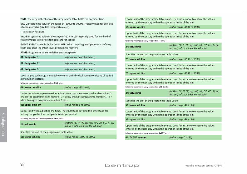
TIME: The very first column of the programme table holds the segment time
VAL L: Programme value in the range of !10000 to 10000. Typically used for any kind of absolute value (like kiln temperature etc.)
: selection not used
VAL S: Programme value in the range of !127 to 128. Typically used for any kind of relative values (like offset temperature for zones)
EVENT: EVENT value, ie. holds ON or OFF. When requiring multiple events defining them one after the other saves programme memory
ATMS: Programme value to define an atmosphere
01:!designator!1 (alphanumerical characters)
02:!designator!2 (alphanumerical characters)
03:!designator!3 (alphanumerical characters)
Used to give each programme table column an individual name (consisting of up to 3 alphanumeric letters)
following parameters apply on selection TIME only: 04:!lower!time!lim (value range !101 to !2)
Limits the value range entered as a time. Note that the values smaller than minus 2 enable the programme link feature (!3 = allow linking to programme number 1, !4 = allow linking to programme number 2 etc.)
05:!upper!time!lim (value range 1 to 6998)
Upper limit when adjusting the time. The 1000 steps beyoind this limit stand for setting the gradient as centigrade kelvin per period
following parameters apply on selection VAL L only:
14:!value!unit (options °C, °F, °K, dg, mV, mA, O2, CO, %, ev, mb, m³, m³h, kh, kwh, Pa, AT, lda)
Specifies the unit of the programme table value
15:!lower!val.!lim (value range !9999 to 9999)
Lower limit of the programme table value. Used for instance to ensure the values entered by the user stay within the operation limits of the kiln
16:!upper!val.!lim (value range !9999 to 9999)
Upper limit of the programme table value. Used for instance to ensure the values entered by the user stay within the operation limits of the kiln
following parameters apply on selection only:
24:!value!unit (options °C, °F, °K, dg, mV, mA, O2, CO, %, ev, mb, m³, m³h, kh, kwh, Pa, AT, lda)
Specifies the unit of the programme table value
25:!lower!val.!lim (value range !9999 to 9999)
Lower limit of the programme table value. Used for instance to ensure the values entered by the user stay within the operation limits of the kiln
26:!upper!val.!lim (value range !9999 to 9999)
Upper limit of the programme table value. Used for instance to ensure the values entered by the user stay within the operation limits of the kiln
following parameters apply on selection VAL S only:
34:!value!unit (options °C, °F, °K, dg, mV, mA, O2, CO, %, ev, mb, m³, m³h, kh, kwh, Pa, AT, lda)
Specifies the unit of the programme table value
35:!lower!val.!lim (value range !99 to 99)
Lower limit of the programme table value. Used for instance to ensure the values entered by the user stay within the operation limits of the kiln
36:!upper!val.!lim (value range !99 to 99)
Upper limit of the programme table value. Used for instance to ensure the values entered by the user stay within the operation limits of the kiln
following parameters apply on selection EVENT only:
44:!EVENT!number (value range 0 to 15)
31operating instructions bentrup TC-S2 V1.1
Configuration
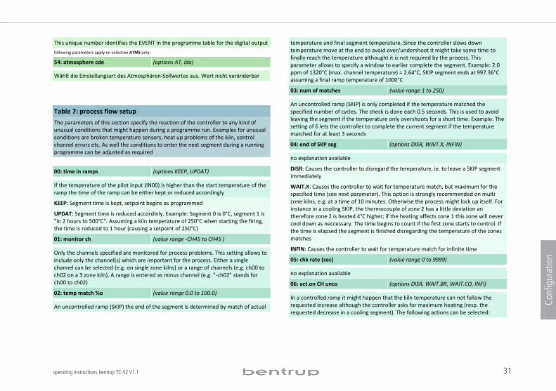
This unique number identifies the EVENT in the programme table for the digital output
following parameters apply on selection ATMS only: 54: atmosphere cde (options AT, lda)
Wählt die Einstellungsart des Atmosphären!Sollwertes aus. Wert nicht veränderbar
Table 7: process flow setup
The parameters of this section specify the reaction of the controller to any kind of unusual conditions that might happen during a programme run. Examples for unusual conditions are broken temperature sensors, heat up problems of the kiln, control channel errors etc. As well the conditions to enter the next segment during a running programme can be adjusted as required . 00: time in ramps (options KEEP, UPDAT)
If the temperature of the pilot input (IN00) is higher than the start temperature of the ramp the time of the ramp can be either kept or reduced accordingly
KEEP: Segment time is kept, setpoint begins as programmed
UPDAT: Segment time is reduced accordinly. Example: Segment 0 is 0°C, segment 1 is "in 2 hours to 500°C". Assuming a kiln temperature of 250°C when starting the firing, the time is reduced to 1 hour (causing a setpoint of 250°C)
01: monitor ch (value range !CH45 to CH45 )
Only the channels specified are monitored for process problems. This setting allows to include only the channel(s) which are important for the process. Either a single channel can be selected (e.g. on single zone kilns) or a range of channels (e.g. ch00 to ch02 on a 3 zone kiln). A range is entered as minus channel (e.g. "!ch02" stands for ch00 to ch02)
02: temp match %o (value range 0.0 to 100.0)
An uncontrolled ramp (SKIP) the end of the segment is determined by match of actual
temperature and final segment temperature. Since the controller slows down temperature move at the end to avoid over/undershoot it might take some time to finally reach the temperature althought it is not required by the process. This parameter allows to specify a window to earlier complete the segment. Example: 2.0 ppm of 1320°C (max. channel temperature) = 2.64°C, SKIP segment ends at 997.36°C assuming a final ramp temperature of 1000°C
03: num of matches (value range 1 to 250)
An uncontrolled ramp (SKIP) is only completed if the temperature matched the specified number of cycles. The check is done each 0.5 seconds. This is used to avoid leaving the segment if the temperature only overshoots for a short time. Example: The setting of 6 lets the controller to complete the current segment if the temperature matched for at least 3 seconds
04: end of SKP seg (options DISR, WAIT.X, INFIN)
no explanation available
DISR: Causes the controller to disregard the temperature, ie. to leave a SKIP segment immediately
WAIT.X: Causes the controller to wait for temperature match, but maximum for the specified time (see next parameter). This option is strongly recommended on multi zone kilns, e.g. at a time of 10 minutes. Otherwise the process might lock up itself. For instance in a cooling SKIP, the thermocouple of zone 2 has a little deviation an therefore zone 2 is heated 4°C higher; if the heating affects zone 1 this zone will never cool down as neccessary. The time begins to count if the first zone starts to control. If the time is elapsed the segment is finished disregarding the temperature of the zones matches
INFIN: Causes the controller to wait for temperature match for infinite time
05: chk rate (sec) (value range 0 to 9999)
no explanation available
06: act.on CH unco (options DISR, WAIT.BR, WAIT.CO, INFI)
In a controlled ramp it might happen that the kiln temperature can not follow the requested increase although the controller asks for maximum heating (resp. the requested decrease in a cooling segment). The following actions can be selected:
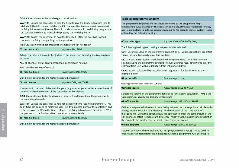
32 operating instructions bentrup TC-S2 V1.1
Configuration
DISR: Causes the controller to disregard this situation
WAIT.BR: Causes the controller to hold the firing to give the kiln temperature time to catch up. If the kiln couldn't catch up within the specified time (see next parameter) the firing is interrupted (break). The hold mode (same as hold used during programme run) can also be released manually by pressing the hold skip button
WAIT.CO: Causes the controller to hold the firing but ! after the time has elapsed !continues the firing disregarding the temperature
INFI: Causes an immediate break if the temperature can not follow.
07: uncontr = ..CH (options ALL, ANY)
Selects the criteria the controller judges to the kiln as non following the temperature increase:
ALL: all channels out of control (maximum or minimum heating)
ANY: any channel out of control
08: max hold (sec) (value range 0 to 9999)
wait time in seconds for the feature specified previously
09: act.on error (options DISR, WAIT.BR)
If any error in the control channels happens (e.g. overtemperature because of break of thermocouple) the reaction of the controller can be adjusted:
DISR: Causes the controller to disregard this event and to continue the process with the remaining channels
WAIT.BR: Causes the controller to hold for a specified time (see next parameter). This delay time can be used to notify the user (e.g. by a process alarm of the controller) and to fix the problem. When the time is elapsed the firing is terminated. Set time to "0" if the process is to be finished after channel error immediately
10: max hold (sec) (value range 0 to 9999)
wait time in seconds for the feature specified previously
.
Table 8: programme setpoint
The programme setpoints are calculated according to the programme resp. temperature curve entered by the operator. Some adjustments are possible for easy operation. Automatic setpoint calculation required for cascade control systems is also entered by the following settings
.
00: setpoint type (options END, CON, MOD, CHA)
The following basic types creating a setpoint can be selected:
CON: Use initial value of the programme segment only. Typical applications are offset values for zone temperatures or flap positions
MOD: Programme setpoint modulated by the segment time. This is the common setting causing the programme setpoint to count upwards resp. downwards over the segment time (e.g. within 2:00 hours from 0°C up to 1000°C)
CHA: Setpoint calculated by cascade control algorithm ! for details refer to the example below
01: process ID (value range a to a )
following parameters apply on selection CON only:
02: table source (value range TA01 to TA19)
Selects the column of the programme table used for setpoint calculation. TA01 is the 1st column, ie. usually the primary temperature
03: offset src SP (value range OFF, SP00 to SP09)
Defines a setpoint which refers to an existing setpoint, ie. the setpoint is calculated by adding another setpoint to it. Used e.g. for the setpoint of the slave zones of a multizone kiln. Using this option allows the operator to enter the temperature of the slave zones as offset (temperature difference) relative to the master zone setpoint. In this example the master zone setpoint is entered in this option
04: idle setpoint (value range !10000 to 10000)
Setpoint whenever the controller is not in a programme run (IDLE). Can be used to ensure a certain temperature is maintained without a programme run. Entering "0"
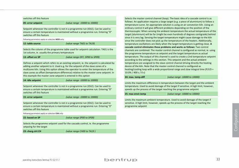
33operating instructions bentrup TC-S2 V1.1
Configuration
switches off this feature
05: error setpoint (value range !10000 to 10000)
Setpoint whenever the controller is not in a programme run (IDLE). Can be used to ensure a certain temperature is maintained without a programme run. Entering "0" switches off this feature
following parameters apply on selection MOD only: 12: table source (value range TA01 to TA19)
Selects the column of the programme table used for setpoint calculation. TA01 is the 1st column, ie. usually the primary temperature
13: offset src SP (value range OFF, SP00 to SP09)
Defines a setpoint which refers to an existing setpoint, ie. the setpoint is calculated by adding another setpoint to it. Used e.g. for the setpoint of the slave zones of a multizone kiln. Using this option allows the operator to enter the temperature of the slave zones as offset (temperature difference) relative to the master zone setpoint. In this example the master zone setpoint is entered in this option
14: idle setpoint (value range !10000 to 10000)
Setpoint whenever the controller is not in a programme run (IDLE). Can be used to ensure a certain temperature is maintained without a programme run. Entering "0" switches off this feature
15: error setpoint (value range !10000 to 10000)
Setpoint whenever the controller is not in a programme run (IDLE). Can be used to ensure a certain temperature is maintained without a programme run. Entering "0" switches off this feature
following parameters apply on selection CHA only: 22: based on SP (value range SP00 to SP09)
Selects the programme setpoint used for the cascade control, ie. the programme setpoing for the target
23: charg.ctrl.CH (value range CH00 to TA19 )
Selects the master control channel (loop). The basic idea of a cascade control is as follows: An application requires a large target (e.g. a piece of aluminium) to follow a temperature curve. An appropriate solution is using an air convection kiln. Using an ordinary control it will give different problems depending on the position of the thermocouple: When sensing the ambient temperature the actual temperature of the target (aluminium) will be far (might be even hundreds of degrees centigrade) behind since it is very lag. Sensing the target temperature might cause damage to the kiln since the controller does not pick up the temperature of the heaters. Additionally, temperature oscillations are likely when the target temperature is getting close. A cascade control eliminates these problems and works as follows: Two control channels are combined. The master control channel is configured as normal, ie. using the programme temperature as setpoint and the target temperature as actual temperature. The output of this channel is used to create a 2nd temperature setpoint according to the settings in this section. This setpoint and the actual ambient temperature are assigned to the slave control channel driving directly the heating device of the kiln. Note that the master control channel is configured as heating/cooling loop with a wide proportional range and slow integral time (P/I/D = 10.0% / 400 s / 0 s)
24: max. temp.diff (value range !10000 to 10000)
Limits the maximum difference in temperature between the target and the ambient temperature. Used to avoid damage of the target if sensitive. A high limit, however, speeds up the process of the target reaching the programme setpoint
25: max envir.temp (value range !10000 to 10000)
Limits the maximum ambient temperature. Used to avoid damage of the target if sensitive. A high limit, however, speeds up the process of the target reaching the programme setpoint
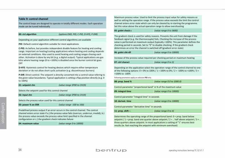
34 operating instructions bentrup TC-S2 V1.1
Configuration
Table 9: control channel
The control loops are designed to operate in totally different modes. Each operation mode can be tuned individually
. 00: ctrl.algorithm (options END, PID, C!PID, D!HYS, P!DIR)
Depending on your application different control algorithms are available
PID: Default control algorithm suitable for most applications
C!PID: As before, but provides independent disable feature for heating and cooling range. Important on heating/cooling applications where heating and cooling depends on external conditions. Also used to avoid heating and cooling ranges chasing each other. Activation is done by any bit (e.g. a digital output). Typical applications are gas kilns where heating range (0 to +100%) is disabled once the burner control bit goes OFF
D!HYS: Hysteresis control for heating devices which require either temperature deviation or do not allow short cyclic activation (e.g. discontinuous burners)
P!DIR: Direct control. The setpoint is directly converted into a control value refering to the given value boundaries. Typical application is setting a flap position directly (e.g. 0 to 100%)
01: setpoint chn (value range SP00 to CH19)
Selects the setpoint used for this control channel
02: input chn (value range SP00 to CH19)
Selects the process value used for this control channel
03: power % on ERR (value range !100 to 100)
Predefined process output if an error occurs in the control channel. The control channel enters error state if a.) the process value fails (overrun, underrun, invalid), b.) the process value exceeds the process value limit specified in the channel configuration or c.) the gradient check indicates failure
04: maximum value (value range 0 to 10000)
Maximum process value. Used to limit the process input value for safety reasons as well as setting the operation range. If the process value exceeds the limit the control channel enters error state which can only be cleared by re!starting the programme. Set this value above the actual operation range to allow overshooting
05: grdnt check s (value range 0 to 3600)
The gradient check is used for safety reasons. Prevents the unit from damage if the feedback signal (e.g. the thermocouple) fails. Checking the increase of the process value is performed on maximum output (typically +100%). This parameter defines the checking period in seconds. Set to "0" to disable checking. If the gradient check determines an error the channel is switched off (gradient error state)
06: grdnt chk dif (value range 0 to 10000)
Increase of the process value required per checking period on maximum heating
07: ctrl charact (value range 0 to 3)
Depending on the application select the operation range of the control channel to one of the following options: 0 = 0% to 100% / 1 = 100% to 0% / 2 = !100% to +100% / 3 = +100% to !100%
following parameters apply on selection PID only:
08: prop. band % (value range 0.0 to 1000.0)
Control parameter "proportional band" in % of the maximum value
09: integral time (value range 0 to 10000)
Control parameter "integral time" in seconds
10: derivat. time (value range 0 to 10000)
Control parameter "derivative time" in seconds
11: prop. shift ¬ (value range 0 to 4)
Determines the operating range of the proportional band: 0 = prop. band below setpoint / 1 = prop. band one quarter above setpoint / 2 = .. half above setpoint / 3 = .. three quarters above setpoint. In most applications a setting of "1" ensures best results (ie. fast reaching the setpoint with minimum overshoot)
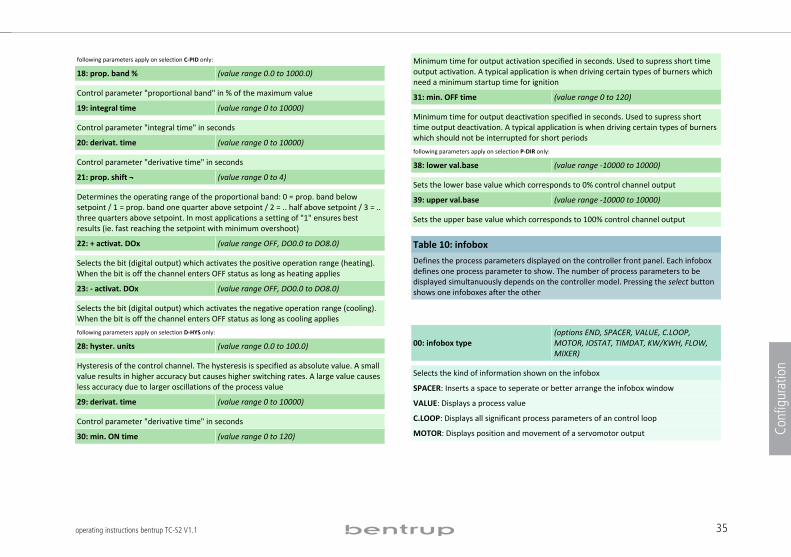
35operating instructions bentrup TC-S2 V1.1
Configuration
following parameters apply on selection C PID only: 18:!prop.!band!% (value range 0.0 to 1000.0)
Control parameter "proportional band" in % of the maximum value
19:!integral!time (value range 0 to 10000)
Control parameter "integral time" in seconds
20:!derivat.!time (value range 0 to 10000)
Control parameter "derivative time" in seconds
21:!prop.!shift!¬ (value range 0 to 4)
Determines the operating range of the proportional band: 0 = prop. band below setpoint / 1 = prop. band one quarter above setpoint / 2 = .. half above setpoint / 3 = .. three quarters above setpoint. In most applications a setting of "1" ensures best results (ie. fast reaching the setpoint with minimum overshoot)
22:!+!activat.!DOx (value range OFF, DO0.0 to DO8.0)
Selects the bit (digital output) which activates the positive operation range (heating). When the bit is off the channel enters OFF status as long as heating applies
23:! !activat.!DOx (value range OFF, DO0.0 to DO8.0)
Selects the bit (digital output) which activates the negative operation range (cooling). When the bit is off the channel enters OFF status as long as cooling applies
following parameters apply on selection D HYS only: 28:!hyster.!units (value range 0.0 to 100.0)
Hysteresis of the control channel. The hysteresis is specified as absolute value. A small value results in higher accuracy but causes higher switching rates. A large value causes less accuracy due to larger oscillations of the process value
29:!derivat.!time (value range 0 to 10000)
Control parameter "derivative time" in seconds
30:!min.!ON!time (value range 0 to 120)
Minimum time for output activation specified in seconds. Used to supress short time output activation. A typical application is when driving certain types of burners which need a minimum startup time for ignition
31:!min.!OFF!time (value range 0 to 120)
Minimum time for output deactivation specified in seconds. Used to supress short time output deactivation. A typical application is when driving certain types of burners which should not be interrupted for short periods
following parameters apply on selection P DIR only:
38:!lower!val.base (value range !10000 to 10000)
Sets the lower base value which corresponds to 0% control channel output
39:!upper!val.base (value range !10000 to 10000)
Sets the upper base value which corresponds to 100% control channel output
Table!10:!infobox
Defines the process parameters displayed on the controller front panel. Each infobox defines one process parameter to show. The number of process parameters to be displayed simultanuously depends on the controller model. Pressing the select button shows one infoboxes after the other
.
00:!infobox!type (options END, SPACER, VALUE, C.LOOP, MOTOR, IOSTAT, TIMDAT, KW/KWH, FLOW, MIXER)
Selects the kind of information shown on the infobox
SPACER: Inserts a space to seperate or better arrange the infobox window
VALUE: Displays a process value
C.LOOP: Displays all significant process parameters of an control loop
MOTOR: Displays position and movement of a servomotor output
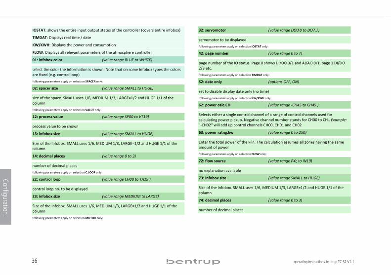
36 operating instructions bentrup TC-S2 V1.1
Configuration
IOSTAT: shows the entire input output status of the controller (covers entire infobox)
TIMDAT: Displays real time / date
KW/KWH: Displays the power and consumption
FLOW: Displays all relevant parameters of the atmosphere controller
01: infobox color (value range BLUE to WHITE)
select the color the information is shown. Note that on some infobox types the colors are fixed (e.g. control loop)
following parameters apply on selection SPACER only: 02: spacer size (value range SMALL to HUGE)
size of the space. SMALL uses 1/6, MEDIUM 1/3, LARGE=1/2 and HUGE 1/1 of the column following parameters apply on selection VALUE only: 12: process value (value range SP00 to VT19)
process value to be shown
13: infobox size (value range SMALL to HUGE)
Size of the Infobox. SMALL uses 1/6, MEDIUM 1/3, LARGE=1/2 and HUGE 1/1 of the column
14: decimal places (value range 0 to 3)
number of decimal places
following parameters apply on selection C.LOOP only: 22: control loop (value range CH00 to TA19 )
control loop no. to be displayed
23: infobox size (value range MEDIUM to LARGE)
Size of the Infobox. SMALL uses 1/6, MEDIUM 1/3, LARGE=1/2 and HUGE 1/1 of the column following parameters apply on selection MOTOR only:
32: servomotor (value range DO0.0 to DO7.7)
servomotor to be displayed
following parameters apply on selection IOSTAT only:
42: page number (value range 0 to 7)
page number of the IO status. Page 0 shows DI/DO 0/1 and AI/AO 0/1, page 1 DI/DO 2/3 etc. following parameters apply on selection TIMDAT only:
52: date only (options OFF, ON)
set to disable display date only (no time)
following parameters apply on selection KW/KWH only:
62: power calc.CH (value range !CH45 to CH45 )
Selects either a single control channel of a range of control channels used for calculating power pickup. Negative channel number stands for CH00 to CH.. Example: "!CH02" will add up control channels CH00, CH01 and CH02
63: power ratng.kw (value range 0 to 250)
Enter the total power of the kiln. The calculation assumes all zones having the same amount of power
following parameters apply on selection FLOW only:
72: flow source (value range P¥ç to IN19)
no explanation available
73: infobox size (value range SMALL to HUGE)
Size of the Infobox. SMALL uses 1/6, MEDIUM 1/3, LARGE=1/2 and HUGE 1/1 of the column
74: decimal places (value range 0 to 3)
number of decimal places
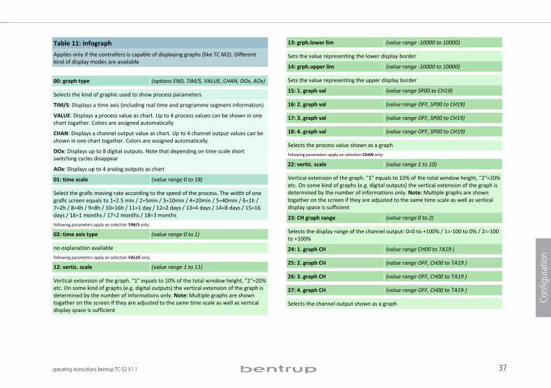
37operating instructions bentrup TC-S2 V1.1
Configuration
Table 11: infograph
Applies only if the controllers is capable of displaying graphs (like TC M2). Different kind of display modes are available . 00: graph type (options END, TIM/S, VALUE, CHAN, DOx, AOx)
Selects the kind of graphic used to show process parameters
TIM/S: Displays a time axis (including real time and programme segment information)
VALUE: Displays a process value as chart. Up to 4 process values can be shown in one chart togather. Colors are assigned automatically
CHAN: Displays a channel output value as chart. Up to 4 channel output values can be shown in one chart togather. Colors are assigned automatically
DOx: Displays up to 8 digital outputs. Note that depending on time scale short switching cycles disappear
AOx: Displays up to 4 analog outputs as chart
01: time scale (value range 0 to 18)
Select the grafic moving rate according to the speed of the process. The width of one grafic screen equals to 1=2.5 min / 2=5min / 3=10min / 4=20min / 5=40min / 6=1h / 7=2h / 8=4h / 9=8h / 10=16h / 11=1 day / 12=2 days / 13=4 days / 14=8 days / 15=16 days / 16=1 months / 17=2 months / 18=3 months
following parameters apply on selection TIM/S only: 02: time axis type (value range 0 to 1)
no explanation available
following parameters apply on selection VALUE only: 12: vertic. scale (value range 1 to 11)
Vertical extension of the graph. "1" equals to 10% of the total window height, "2"=20% etc. On some kind of graphs (e.g. digital outputs) the vertical extension of the graph is determined by the number of informations only. Note: Multiple graphs are shown togather on the screen if they are adjusted to the same time scale as well as vertical display space is sufficient
13: grph.lower lim (value range !10000 to 10000)
Sets the value representing the lower display border
14: grph.upper lim (value range !10000 to 10000)
Sets the value representing the upper display border
15: 1. graph val (value range SP00 to CH19)
16: 2. graph val (value range OFF, SP00 to CH19)
17: 3. graph val (value range OFF, SP00 to CH19)
18: 4. graph val (value range OFF, SP00 to CH19)
Selects the process value shown as a graph
following parameters apply on selection CHAN only:
22: vertic. scale (value range 1 to 10)
Vertical extension of the graph. "1" equals to 10% of the total window height, "2"=20% etc. On some kind of graphs (e.g. digital outputs) the vertical extension of the graph is determined by the number of informations only. Note: Multiple graphs are shown togather on the screen if they are adjusted to the same time scale as well as vertical display space is sufficient
23: CH graph range (value range 0 to 2)
Selects the display range of the channel output: 0=0 to +100% / 1=!100 to 0% / 2=!100 to +100%
24: 1. graph CH (value range CH00 to TA19 )
25: 2. graph CH (value range OFF, CH00 to TA19 )
26: 3. graph CH (value range OFF, CH00 to TA19 )
27: 4. graph CH (value range OFF, CH00 to TA19 )
Selects the channel output shown as a graph
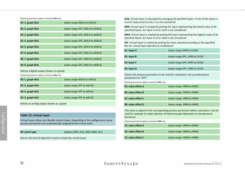
38 operating instructions bentrup TC-S2 V1.1
Configuration
following parameters apply on selection DOx only: 32: 1. graph DOx (value range DO0.0 to DO8.0)
33: 2. graph DOx (value range OFF, DO0.0 to DO8.0)
34: 3. graph DOx (value range OFF, DO0.0 to DO8.0)
35: 4. graph DOx (value range OFF, DO0.0 to DO8.0)
36: 5. graph DOx (value range OFF, DO0.0 to DO8.0)
37: 6. graph DOx (value range OFF, DO0.0 to DO8.0)
38: 7. graph DOx (value range OFF, DO0.0 to DO8.0)
39: 8. graph DOx (value range OFF, DO0.0 to DO8.0)
Selects a digital output shown as a graph following parameters apply on selection AOx only: 42: 1. graph AOx (value range AO0.0 to AO4.0)
43: 2. graph AOx (value range OFF to AO4.0)
44: 3. graph AOx (value range OFF to AO4.0)
45: 4. graph AOx (value range OFF to AO4.0)
Selects an analog output shown as a graph
Table 12: virtual input
Virtual inputs allow very flexible control loops. Depending to the configuration setup process parameters are automatically assigned to the virtual input
. 00: select type (options END, AVG, MIN, MAX, SEL)
Selects the kind of algorithm used to create the virtual input:
AVG: Virtual input is calculated by averaging all specified inputs. If one of the inputs is in error state (overrun etc.) it is not considered
MIN: Virtual input is created by picking the input representing the lowest value of all specified inputs. An input in error state is not considered
MAX: Virtual input is created by picking the input representing the highest value of all specified inputs. An input in error state is not considered
SEL: Virtual input is created by picking the input selected according to the specified bits (ie. virtual input operates as multiplexer)
01: input A (value range SP00 to CH19)
02: input B (value range OFF, SP00 to CH19)
03: input C (value range OFF, SP00 to CH19)
04: input D (value range OFF, SP00 to CH19)
Selects the process parameters to be used for calculation. Set unused process parameters to "OFF"
following parameters apply on selection AVG only:
05: value offset A (value range !9999 to 9999)
06: value offset B (value range !9999 to 9999)
07: value offset C (value range !9999 to 9999)
08: value offset D (value range !9999 to 9999)
This value is added to the corresponding process parameter before calculation. Can be used for example to make selection of thermocouple dependant on temperature deviations following parameters apply on selection MIN only:
15: value offset A (value range !9999 to 9999)
16: value offset B (value range !9999 to 9999)
17: value offset C (value range !9999 to 9999)
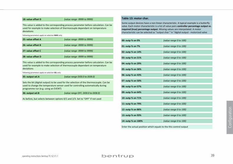
39operating instructions bentrup TC-S2 V1.1
Configuration
18: value offset D (value range !9999 to 9999)
This value is added to the corresponding process parameter before calculation. Can be used for example to make selection of thermocouple dependant on temperature deviations following parameters apply on selection MAX only: 25: value offset A (value range !9999 to 9999)
26: value offset B (value range !9999 to 9999)
27: value offset C (value range !9999 to 9999)
28: value offset D (value range !9999 to 9999)
This value is added to the corresponding process parameter before calculation. Can be used for example to make selection of thermocouple dependant on temperature deviations following parameters apply on selection SEL only: 35: output sel.A (value range DO0.0 to DO8.0)
Sets the bit (digital output) to be used for the selection of the thermocouple. Can be used to change the temperature sensor used for controlling automatically during programme run (e.g. using an EVENT)
36: output sel.B (value range OFF, DO0.0 to DO8.0)
As before, but selects between options 0/1 and 2/3. Set to "OFF" if not used
Table 13: motor char.
Some output devices have a non!linear characteristic. A typical example is a butterfly valve. Each motor characteristic is a list of value pairs controller percentage output vs. required (true) percentage output. Missing values are interpolated. A motor characteristic can be selected as "output char." in "digital output ! motorized valve .
00: outp % on 0% (value range 0 to 100)
01: outp % on 7% (value range 0 to 100)
02: outp % on 14% (value range 0 to 100)
03: outp % on 21% (value range 0 to 100)
04: outp % on 29% (value range 0 to 100)
05: outp % on 36% (value range 0 to 100)
06: outp % on 43% (value range 0 to 100)
07: outp % on 50% (value range 0 to 100)
08: outp % on 57% (value range 0 to 100)
09: outp % on 64% (value range 0 to 100)
10: outp % on 71% (value range 0 to 100)
11: outp % on 79% (value range 0 to 100)
12: outp % on 86% (value range 0 to 100)
13: outp % on 93% (value range 0 to 100)
14: outp % on 100% (value range 0 to 100)
Enter the actual position which equals to the this control output
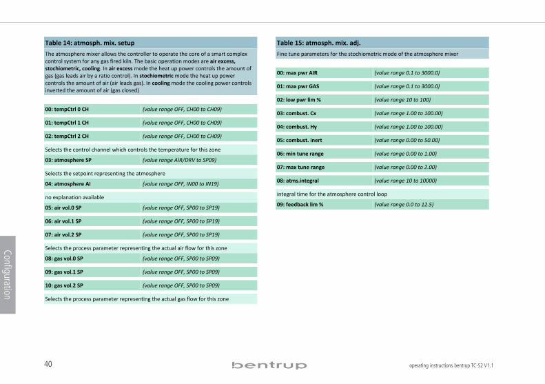
40 operating instructions bentrup TC-S2 V1.1
Configuration
Table 14: atmosph. mix. setup
The atmosphere mixer allows the controller to operate the core of a smart complex control system for any gas fired kiln. The basic operation modes are air excess, stochiometric, cooling. In air excess mode the heat up power controls the amount of gas (gas leads air by a ratio control). In stochiometric mode the heat up power controls the amount of air (air leads gas). In cooling mode the cooling power controls inverted the amount of air (gas closed) . 00: tempCtrl 0 CH (value range OFF, CH00 to CH09)
01: tempCtrl 1 CH (value range OFF, CH00 to CH09)
02: tempCtrl 2 CH (value range OFF, CH00 to CH09)
Selects the control channel which controls the temperature for this zone
03: atmosphere SP (value range AIR/DRV to SP09)
Selects the setpoint representing the atmosphere
04: atmosphere AI (value range OFF, IN00 to IN19)
no explanation available
05: air vol.0 SP (value range OFF, SP00 to SP19)
06: air vol.1 SP (value range OFF, SP00 to SP19)
07: air vol.2 SP (value range OFF, SP00 to SP19)
Selects the process parameter representing the actual air flow for this zone
08: gas vol.0 SP (value range OFF, SP00 to SP09)
09: gas vol.1 SP (value range OFF, SP00 to SP09)
10: gas vol.2 SP (value range OFF, SP00 to SP09)
Selects the process parameter representing the actual gas flow for this zone
Table 15: atmosph. mix. adj.
Fine tune parameters for the stochiometric mode of the atmosphere mixer .
00: max pwr AIR (value range 0.1 to 3000.0)
01: max pwr GAS (value range 0.1 to 3000.0)
02: low pwr lim % (value range 10 to 100)
03: combust. Cx (value range 1.00 to 100.00)
04: combust. Hy (value range 1.00 to 100.00)
05: combust. inert (value range 0.00 to 50.00)
06: min tune range (value range 0.00 to 1.00)
07: max tune range (value range 0.00 to 2.00)
08: atms.integral (value range 10 to 10000)
integral time for the atmosphere control loop
09: feedback lim % (value range 0.0 to 12.5)
.
.

operating instructions bentrup TC-S2 V1.1 (C)2009 bentrup Industriesteuerungen Germany
www.bentrup.com