unified facilities criteria (ufc) lonworks … · ufc 3-410-02 19 nov 2008 unified facilities...
TRANSCRIPT
UFC 3-410-02 19 Nov 2008
UNIFIED FACILITIES CRITERIA (UFC)
LONWORKS® DIRECT DIGITAL CONTROL FOR HVAC AND OTHER
LOCAL BUILDING SYSTEMS
APPROVED FOR PUBLIC RELEASE; DISTRIBUTION UNLIMITED

UFC 3-410-02 19 Nov 2008
UNIFIED FACILITIES CRITERIA (UFC)
LONWORKS® DIRECT DIGITAL CONTROLS FOR HVAC AND OTHER LOCAL BUILDING SYSTEMS
Any copyrighted material included in this UFC is identified at its point of use. Use of the copyrighted material apart from this UFC must have the permission of the copyright holder. U.S. ARMY CORPS OF ENGINEERS (Preparing Activity) NAVAL FACILITIES ENGINEERING COMMAND AIR FORCE CIVIL ENGINEER SUPPORT AGENCY Record of Changes (changes are indicated by \1\ ... /1/) Change No. Date Location
This UFC supersedes: UFC 3-410-02A

UFC 3-410-02 19 Nov 2008
FOREWORD The Unified Facilities Criteria (UFC) system is prescribed by MIL-STD 3007 and provides planning, design, construction, sustainment, restoration, and modernization criteria, and applies to the Military Departments, the Defense Agencies, and the DoD Field Activities in accordance with USD(AT&L) Memorandum dated 29 May 2002. UFC will be used for all DoD projects and work for other customers where appropriate. All construction outside of the United States is also governed by Status of forces Agreements (SOFA), Host Nation Funded Construction Agreements (HNFA), and in some instances, Bilateral Infrastructure Agreements (BIA.) Therefore, the acquisition team must ensure compliance with the more stringent of the UFC, the SOFA, the HNFA, and the BIA, as applicable. UFC are living documents and will be periodically reviewed, updated, and made available to users as part of the Services’ responsibility for providing technical criteria for military construction. Headquarters, U.S. Army Corps of Engineers (HQUSACE), Naval Facilities Engineering Command (NAVFAC), and Air Force Civil Engineer Support Agency (AFCESA) are responsible for administration of the UFC system. Defense agencies should contact the preparing service for document interpretation and improvements. Technical content of UFC is the responsibility of the cognizant DoD working group. Recommended changes with supporting rationale should be sent to the respective service proponent office by the following electronic form: Criteria Change Request (CCR). The form is also accessible from the Internet sites listed below. UFC are effective upon issuance and are distributed only in electronic media from the following source: Whole Building Design Guide web site http://dod.wbdg.org/. Hard copies of UFC printed from electronic media should be checked against the current electronic version prior to use to ensure that they are current. AUTHORIZED BY: ______________________________________ JAMES C. DALTON, P.E. Chief, Engineering and Construction U.S. Army Corps of Engineers
______________________________________JOSEPH E. GOTT, P.E. Chief Engineer Naval Facilities Engineering Command
______________________________________ PAUL A. PARKER The Deputy Civil Engineer DCS/Installations & Logistics Department of the Air Force
______________________________________Dr. GET W. MOY, P.E. Director, Installations Requirements and Management Office of the Deputy Under Secretary of Defense (Installations and Environment)

UFC 3-410-02 19 Nov 2008
i
CONTENTS CONTENTS ..................................................................................................................... i FIGURES ........................................................................................................................iv TABLES .......................................................................................................................... v CHAPTER 1 INTRODUCTION........................................................................................ 1
1-1 BACKGROUND ................................................................................................ 1 1-2 PURPOSE ........................................................................................................ 2 1-3 SCOPE ............................................................................................................. 3
1-3.1 HVAC control ............................................................................................. 3 1-3.2 Building control network............................................................................. 3 1-3.3 UMCS interface ......................................................................................... 3 1-3.4 Other systems............................................................................................ 4
1-4 APPLICABILITY................................................................................................ 4 1-5 REFERENCES ................................................................................................. 4
CHAPTER 2 CONTROL SYSTEM NETWORK............................................................... 6 2-1 INTRODUCTION .............................................................................................. 6 2-2 ARCHITECTURE.............................................................................................. 6 2-3 BUILDING CONTROL NETWORK ................................................................... 7
2-3.1 General ...................................................................................................... 7 2-3.2 TP/FT-10 media......................................................................................... 7 2-3.3 Other media types ..................................................................................... 8 2-3.4 Media selection.......................................................................................... 8 2-3.5 Building control network - backbone .......................................................... 9 2-3.6 Building control network - local control bus................................................ 9
2-4 CONNECTION TO A UMCS........................................................................... 10 2-5 NETWORK DESIGN AND LAYOUT ............................................................... 10 2-6 NETWORK HARDWARE................................................................................ 10
2-6.1 Repeater .................................................................................................. 10 2-6.2 Media converter ....................................................................................... 10 2-6.3 Router ...................................................................................................... 10 2-6.4 Network bandwidth .................................................................................. 11 2-6.5 Other architecture issues ......................................................................... 12
2-7 ADDRESSING, DATA TRANSMISSION, AND DATA INTEGRITY ................ 13 2-7.1 Addressing............................................................................................... 13 2-7.2 Data transmission .................................................................................... 14 2-7.3 Data integrity............................................................................................ 16
CHAPTER 3 DIRECT DIGITAL CONTROL HARDWARE AND CONTROL DEVICES. 17 3-1 INTRODUCTION ............................................................................................ 17
3-1.1 SNVTs ..................................................................................................... 17 3-1.2 Functional profile ..................................................................................... 17
3-2 DDC HARDWARE .......................................................................................... 17 3-2.1 Application specific controller................................................................... 19 3-2.2 Application generic controller................................................................... 19 3-2.3 General purpose programmable controller .............................................. 20 3-2.4 Local display panel .................................................................................. 20

UFC 3-410-02 19 Nov 2008
ii
3-2.5 CEA-709.1 sensors and actuators ........................................................... 20 3-2.6 Building management interface ............................................................... 21
3-3 FIELD DEVICES ............................................................................................. 21 3-3.1 Sensors (input devices) ........................................................................... 21 3-3.2 Actuators (output devices) ....................................................................... 21 3-3.3 Multi-function devices .............................................................................. 21
CHAPTER 4 TYPICAL CONTROL LOOPS .................................................................. 23 4-1 INTRODUCTION ............................................................................................ 23 4-2 BASIC CONTROL LOOP................................................................................ 23
4-2.1 Control action and device failsafe ............................................................ 23 4-3 CONTROL LOGIC DIAGRAMS ...................................................................... 25
4-3.1 Control logic diagram basic sequence ..................................................... 25 4-3.2 System enabling logic .............................................................................. 27 4-3.3 Alarms and shutdown CLD ...................................................................... 28
4-4 CONTROL LOOPS ......................................................................................... 30 4-4.1 Preheat coil control loop .......................................................................... 30 4-4.2 Cooling coil control loop........................................................................... 32 4-4.3 Heating coil control loop with setpoint reset............................................. 33 4-4.4 Mixed air temperature control with economizer ....................................... 35 4-4.5 Outside air flow control ............................................................................ 45 4-4.6 Variable air volume control loops............................................................. 48 4-4.7 Variable speed pump control ................................................................... 58 4-4.8 Humidity control loop ............................................................................... 62 4-4.9 Alarms...................................................................................................... 66
CHAPTER 5 CONTROL SYSTEM DRAWINGS ........................................................... 68 5-1 CONTROL SYSTEM DRAWINGS OVERVIEW.............................................. 68 5-2 CONTRACT DRAWING SET.......................................................................... 68 5-3 SYMBOLS AND UNIQUE IDENTIFIERS........................................................ 69 5-4 POINTS SCHEDULE ...................................................................................... 71
5-4.1 Overview.................................................................................................. 71 5-4.2 Responsibilities........................................................................................ 71 5-4.3 UMCS content shown on UFGS 25 10 10 points schedules.................... 71 5-4.4 Points schedule description and instructions ........................................... 71 5-4.5 Points schedule application notes............................................................ 75
5-5 CONTROL SYSTEM SCHEMATIC................................................................. 78 5-5.1 Loops and devices................................................................................... 79 5-5.2 Sequencing diagrams .............................................................................. 79 5-5.3 Designer notes......................................................................................... 79
5-6 LADDER DIAGRAM........................................................................................ 79 5-7 CONTROL LOGIC DIAGRAM......................................................................... 80 5-8 SEQUENCE OF OPERATION........................................................................ 81 5-9 THERMOSTAT AND OCCUPANCY SENSOR SCHEDULE .......................... 81
5-9.1 Thermostats............................................................................................. 81 5-9.2 Occupancy sensors ................................................................................. 82 5-9.3 Schedule entries ...................................................................................... 82
5-10 OCCUPANCY SCHEDULE......................................................................... 83 5-10.1 System default schedule.......................................................................... 83
UFC 3-410-02 19 Nov 2008
iii
5-10.2 Supervisory monitoring and control schedule .......................................... 83 5-10.3 Number of occupancy sensors to put AHU in occupied mode ................. 83
CHAPTER 6 PROJECT IMPLEMENTATION................................................................ 84 6-1 INTRODUCTION ............................................................................................ 84 6-2 PLANNING...................................................................................................... 84 PROCUREMENT CONSIDERATIONS ..................................................................... 84
6-2.1 Non-proprietary procurement................................................................... 84 6-2.2 Proprietary procurement .......................................................................... 84
6-3 DDC DESIGN ................................................................................................. 85 6-3.1 General .................................................................................................... 85
6-4 SCOPE OF THE DESIGN............................................................................... 85 6-5 CONTRACTING MECHANISMS .................................................................... 88 6-6 COORDINATION ............................................................................................ 89
6-6.1 IT (DOIM) Coordination............................................................................ 89 6-6.2 Mechanical design coordination............................................................... 89 6-6.3 Electrical design coordination .................................................................. 90 6-6.4 Project site coordination........................................................................... 90
6-7 EDITING THE SPECIFICATION..................................................................... 91 6-7.1 UFGS 23 09 23 edits ............................................................................... 91 6-7.2 Other specification editing/coordination ................................................... 91
6-8 DRAWING PACKAGE .................................................................................... 92 6-9 Other............................................................................................................... 92
APPENDIX A GLOSSARY ............................................................................................ 93 APPENDIX B CONTROL LOGIC DIAGRAM (CLD) TUTORIAL ................................... 98
B-1 Introduction ..................................................................................................... 98 B-2 Functional blocks used in control logic diagrams ............................................ 98
B-2.1 Signal....................................................................................................... 98 B-2.2 Actuator Output........................................................................................ 99 B-2.3 Sensor Input ............................................................................................ 99 B-2.4 Hand-Off-Auto (H-O-A) Switch................................................................. 99 B-2.5 Constant Value ........................................................................................ 99 B-2.6 Signal I/O ............................................................................................... 100 B-2.7 Logical AND........................................................................................... 100 B-2.8 Logical NOT........................................................................................... 100 B-2.9 Logical OR............................................................................................. 100 B-2.10 On Delay Timer...................................................................................... 100 B-2.11 Switch .................................................................................................... 101 B-2.12 Comparator with Deadband ................................................................... 101 B-2.13 Reset Schedule ..................................................................................... 102 B-2.14 Math Function ........................................................................................ 102 B-2.15 PID Loop with Enable ............................................................................ 103

UFC 3-410-02 19 Nov 2008
iv
FIGURES Figure 2-1. UMCS and DDC System Architecture........................................................... 7 Figure 4-1. Basic Control Loop..................................................................................... 23 Figure 4-2. Direct Control Action .................................................................................. 24 Figure 4-3. Reverse Control Action .............................................................................. 25 Figure 4-4. Basic Sequence for a Cooling Coil Control Loop. ...................................... 26 Figure 4-5. System Enabling Logic. ............................................................................. 28 Figure 4-6. Alarms and Shutdown CLD........................................................................ 30 Figure 4-7. Preheat Coil Control Schematic. ................................................................. 31 Figure 4-8. Preheat Coil CLD. ...................................................................................... 31 Figure 4-9. Cooling Coil Control Schematic. ................................................................ 33 Figure 4-10. Cooling Coil CLD. .................................................................................... 33 Figure 4-11. Typical Setpoint Reset Schedule for Heating Coil Air Temperature......... 34 Figure 4-12. Heating Coil with Outside Air Reset Control Schematic. .......................... 35 Figure 4-13. Economizer/Mixed Air Temperature Control Schematic........................... 36 Figure 4-14. OA-Only Dry Bulb Economizer CLD. ....................................................... 37 Figure 4-15. OA-Only Economizer Setpoint Selection Example for Greenville, NC. ... 39 Figure 4-16. Greenville SC Weather Data for OA-Only Economizer Setpoint Selection Example. ....................................................................................................................... 40 Figure 4-17. Mixed Air Temperature Control with RA/OA Activated Economizer CLD. 42 Figure 4-18. OA/RA Economizer Differential Setpoint Selection. ................................. 43 Figure 4-19. Greenville SC Weather Data for OA/RA Economizer Setpoint Selection Example. ....................................................................................................................... 44 Figure 4-20. Minimum OA Using Two-Position Damper CLD....................................... 46 Figure 4-21. Minimum OA Flow CLD............................................................................ 47 Figure 4-22. Supply Duct Static Pressure Control Schematic. ...................................... 49 Figure 4-23. Supply Duct Static Pressure CLD. ........................................................... 49 Figure 4-24. Supply Duct Static Pressure Setpoint Reset. ........................................... 50 Figure 4-25. Supply Duct Static Pressure Setpoint Reset, Setpoint Calculation. ......... 50 Figure 4-26. Supply Duct Static Pressure Setpoint Reset, Ramp-up / Ramp-down. .... 51 Figure 4-27. Return Fan Flow Control Schematic. ....................................................... 55 Figure 4-28. Return Fan Flow CLD. ............................................................................. 56 Figure 4-29. Air Flows in a Return Fan System............................................................ 57 Figure 4-30. Primary/Secondary Pumping Control Schematic. .................................... 59 Figure 4-31. Variable Speed (Secondary) Pump CLD.................................................. 60 Figure 4-32. Variable Speed (Secondary) Pump Control - Ladder Diagram. ................ 61 Figure 4-33. Humidity Control System Schematic. ....................................................... 63 Figure 4-34. Humidity Control Sequencing Diagrams. .................................................. 63 Figure 4-35. Cooling and Dehumidification CLD. .......................................................... 64 Figure 4-36. Dehumidification / Humidification Sequencing CLD. ................................. 64 Figure 4-37. Reheat Coil CLD. ...................................................................................... 65 Figure 4-38. Humidifier CLD.......................................................................................... 65 Figure 5-1. Generic Device Symbols............................................................................. 69 Figure 5-2. Sample Ladder Diagram. ............................................................................ 80 Figure 5-3. Thermostat and Occupancy Sensor Schedule........................................... 81 Figure 6-1. UMCS Decision Flow Chart. ....................................................................... 86

UFC 3-410-02 19 Nov 2008
v
TABLES Table 5-1: System Reset Button Options and Points Schedule Entries ........................ 76

UFC 3-410-02 19 Nov 2008
1
CHAPTER 1
INTRODUCTION
1-1 BACKGROUND Designers, installers, and operation and maintenance (O&M) staff have struggled with the complexities and incompatibilities of multi-vendor building automation direct digital control (DDC) systems almost since they were introduced in the 1980’s. DDC systems are routinely designed and procured on a building-by-building or sub-system by sub-system basis, most notably for heating, ventilating, and air-conditioning (HVAC) systems. In the absence of specifications and criteria for Open systems, Government procurement rules which require competitive bidding make it extremely difficult if not impossible to procure new DDC systems that are compatible with existing ones and that are also compatible with a basewide or campus-wide supervisory system. In the absence of sole-source procurement, new but incompatible DDC systems result at best in inefficiencies and at worst in complex and non-functioning systems. This is a problem with system-to-system data sharing and is a problem where multiple individual systems need to communicate with a supervisory monitoring and control (front-end) system such as a Utility Monitoring and Control System (UMCS) specified by UFGS 25 10 10. This inability to interoperate is a result of Closed systems due to vendor-specific proprietary elements. In contrast, Open DDC systems are now available. An Open DDC system is characterized by the ability for any qualified entity to readily modify, operate, upgrade, and perform retrofits on the DDC system. An Open system:
• Permits multiple devices from multiple vendors to readily exchange information. • Provides the capability to easily replace any device with another device procured
from multiple sources. • May have proprietary components within devices, but these proprietary
components must be a small percentage of the overall device. • May have fees associated with use of certain components.
In short, an Open system is one (integrated, multi-vendor) system where there is no future dependence on any one Contractor or controls vendor. Open communications and data sharing between multi-vendor systems and with a third party supervisory system is necessary to achieve effective system operation. Some of the benefits and capabilities of Open multi-vendor DDC systems include:
• Competitive procurement, most notably at the building and sub-system level.
UFC 3-410-02 19 Nov 2008
2
• An operator workstation/user interface that provides for the same look and feel
for monitoring and control regardless of which vendor’s DDC system or sub-system an operator is viewing. As a result, system operators need only become proficient with one user interface.
• An operator workstation/user interface (software) that provides for management
of base-wide system operations such as: remote alarm reporting, remote scheduling (on/off control), remote set point override, data logging and reports, energy management including load shedding, utilities monitoring/measurement for the purpose of monitoring energy performance contracts, and initial diagnosis of service calls. As a result, through a single user interface, system operators and managers are afforded the means to efficiently and effectively manage base-wide operations.
• A whole-building approach to systems integration. This includes the efficient
inter-connection of HVAC control sub-systems. For example, terminal unit equipment, such as VAV boxes can be readily interfaced to the servicing air handler to provide a call for cooling. In addition, the whole-building approach provides the capability for integrating non-HVAC sub-systems such as fire and security
• Groundwork for establishment of a non-proprietary and openly accessible ‘point-
database’ in support of communications-network management requirements. The Open database approach further insulates the government from the possibility of single vendor lock-in and resulting proprietary procurement.
1-2 PURPOSE This UFC is intended to be used with UFGS 23 09 23 (LonWorks® Direct Digital Control for HVAC and Other Local Building Systems). The design concept described in this UFC provides definitive guidance intended to streamline DDC system design and installation leading to maintainable, interoperable, extensible, and non-proprietary control systems. The purpose of this UFC is two-fold;
• Commonality. Describe a definitive methodology for the design of building-level control systems and strategies (primarily for HVAC) where the intent is to achieve at least a degree of commonality in systems designed and procured through different channels.
• Compatibility. Describe a definitive methodology to obtain multi-vendor systems
that can communicate and interoperate with each other and with a supervisory monitoring and control system such as a basewide UMCS through the use of an Open communications protocol.
UFC 3-410-02 19 Nov 2008
3
The Open systems approach described in this UFC is based on ANSI/CEA standard 709.1-B communications protocol (sometimes referred to as LonTalk®) and on LONWORKS® Network Services (LNS®) network operating system. The standard protocol supports Open communications while LNS supports Open network management. The design of an Open system is not simple. It requires attention to a great deal of detail. This UFC, the specifications, and accompanying drawings were developed to minimize the time and effort required on the part of the designer. The level of detail contained in this UFC is necessary because of the variety of approaches that can be used to implement ANSI/CEA-709.1-B where, in the absence of this detail, would very likely result in incompatible systems. 'CEA-709.1' is used in this UFC as the shorthand reference to the ANSI/CEA standard 709.1-B communications protocol. In this UFC the term LONWORKS® is used to loosely describe a collection of technologies (including hardware, and software), vendors and installers relating to or based on the CEA-709.1 communications protocol.
1-3 SCOPE This UFC describes the design of HVAC control systems and the associated building control network that can interface to a UMCS in an Open and non-proprietary manner. The guidance also provides a foundation for the design of other Open building systems.
1-3.1 HVAC control This UFC provides Open DDC systems guidance for the design of heating, ventilating and air conditioning (HVAC) control systems and other building-level systems, sub-systems and equipment including: primary (air and water) built-up systems, terminal units, and packaged equipment.
1-3.2 Building control network This UFC describes designer selections for the Building Control Network (BCN) communications including data exchange, architecture, and cabling.
1-3.3 UMCS interface The DDC system can function as a stand-alone system with reduced functionality (limited user interface, no trending etc.) but is intended to be integrated with a UMCS in accordance with the UMCS guidance (UFC 3-401-01 and UFGS 25 10 10) to provide for remote supervisory monitoring and control of the DDC system. This UFC (3-410-02) and UFGS 23 09 23 helps to ensure that the building-level control system is capable of being interconnected with a UMCS. Even in the absence of a UMCS, this UFC describes the methodology for designer selection and specification of data exchange

UFC 3-410-02 19 Nov 2008
4
parameters including requirements that will facilitate subsequent non-proprietary UMCS interface.
1-3.4 Other systems Although not directly addressed or specified in the UFC or UFGS the methodology, approach, and many of the requirements defined in this UFC and UFGS 23 09 23 can be used to design other (non-HVAC) Open DDC systems such as water and sanitary sewer systems, electrical systems, lighting, and other utility systems and equipment.
1-4 APPLICABILITY This UFC and accompanying UFGS 25 10 10 'LonWorks Utility Monitoring and Control System' are for use on all USACE and AFCESA projects. The NAVFAC standard is to use BACnet for its DDC communication protocol and NAVFAC systems should use UFGS 23 09 23.13 20 'BACnet Direct Digital Control Systems for HVAC'. NAVFAC allows the use of LonWorks for upgrades and additions to legacy systems. At the discretion of and with approval from the assigning government agency (such as the responsible Corps of Engineers District) the control system designer may deviate from the approach defined in this UFC. When deviating from this guidance, systems based on an Open communications protocol are recommended and systems that lead to subsequent proprietary procurement or single-vendor systems are discouraged.
1-5 REFERENCES American National Standards Institute/Consumer Electronics Association:
• ANSI/CEA-709.1-B, Control Network Protocol Specification, 2002 • ANSI/CEA-709.3, Free-Topology Twisted-Pair Channel Specification, 1998. • ANSI/CEA-852, Tunneling Component Network Protocols Over Internet Protocol
Channels, 2001. Headquarters, U.S. Army Corps of Engineers (HQUSACE)
• UFGS 25 10 10, LONWORKS® UTILITY MONITORING AND CONTROL SYSTEM (UMCS), 2008.
• UFGS 23 09 23, LONWORKS® DIRECT DIGITAL CONTROL FOR HVAC AND OTHER LOCAL BUILDING SYSTEMS, 2008.
• UFC 3-401-01FA, LONWORKS® UTILITY MONITORING AND CONTROL SYSTEM (UMCS), 2008.
LonMark International

UFC 3-410-02 19 Nov 2008
5
• LonMark Interoperability Guidelines, LonMark Application-Layer Interoperability Guide version 3.4, 2005 and LonMark layer 1-6 Interoperability Guide version 3.4, 2005.
• LonMark XIF Guide, LonMark Device Interface File Reference Guide version 4.401, 2005.
• LonMark SNVT Master List, LonMark Standard Network Variable Type (SNVT) Master List version 12, 2003.
• LonMark SCPT Master List, LonMark Standard Configuration Property Type (SCPT) Master List version 12, 2003.
• LonMark Standard Enumeration Master List, LonMark Standard Enumeration Master List version 12, 2003.

UFC 3-410-02 19 Nov 2008
6
CHAPTER 2
CONTROL SYSTEM NETWORK
2-1 INTRODUCTION This chapter describes building-level Open-communications control system architecture, device functionality, and control devices for HVAC and other building-level monitoring and control applications. The communications network and devices are based on LonWorks® technology and CEA-709.1 communications protocol. Design of an Open-communications building-level control system does not require an extensive familiarity with the CEA-709.1 protocol, but it is critical that the designer understand that the protocol can be implemented in a manner that is not Open and thus can lead to incompatible systems. Therefore, this chapter contains information pertinent to the design of an Open system that designers likely are not familiar with due to the complex nature of modern networked control systems. While many design decisions have already been made, this chapter describes concepts and selections that the designer should be familiar with when developing a project-specific design.
2-2 ARCHITECTURE As illustrated in Figure 2-1 a basewide system consists of a UMCS (specified by UFGS 25 10 10) connected to one or more building-level DDC systems (specified by UFGS 23 09 23). The network architecture consists of a basewide IP network and one or more building-level TP/FT-10 networks. DDC UFGS 23 09 23 refers to the building-level TP/FT-10 network as the Building Control Network (BCN). A building point of connection (BPOC) provides an interface between the IP and BCN networks. Generally, the UMCS will be a basewide system, but it may initially consist of only one (or a few) building control networks with the capability of being expanded to include additional buildings where multiple building control networks can be connected to a single UMCS via a BPOC router at each building.

UFC 3-410-02 19 Nov 2008
7
Figure 2-1. UMCS and DDC System Architecture.
2-3 BUILDING CONTROL NETWORK
2-3.1 General As illustrated in Figure 2-1 UFGS 23 09 23 specifies the building control network (BCN) and requires the use of CEA-709.1 communications protocol over a TP/FT-10 network (in accordance with CEA-709.3) connected in a doubly-terminated topology. The BCN consists of a backbone with one or more local control buses connected to it via routers. This produces a logically flat network in the building where each node can communicate directly with any other node without the intervention of another controller.
2-3.2 TP/FT-10 media TP/FT-10 defines a network media and transceiver type:
• The TP in TP/FT-10 stands for Twisted Pair. This is a description of the media that is used to connect the controllers. In this case, a twisted pair of wires is used. CEA-709.3 requires that this twisted pair meet the requirements of CAT-5
Basewide ANSI 709.1B over IP Network (EIA-852) >=100Mbps
BPOCRouter
RTR
RTR
RTRMore devices
and/or ‘subnets’
RTR
More devices. No more RTRs or
RPTRs
RTR
More devices. No more RTRs
or RPTRs
AN
SI 7
09.1
B o
ver T
P/FT
-10
(IAW
AN
SI 7
09.3
)
One or more workstation running: -GUI Clients -Network Management Tool Clients -Web Clients (optional)
One or more servers running: -LNS Server -Network Management Tool -Graphical User Interface (GUI) -Monitoring and Control Software -Web Server (optional)
UFG
S 23 09 23
UFGS 25 10 10
RTRnon-ANSI 709.1legacy system
BPOCGateway
RTR=RouterBPOC=Building Point Of ConnectionCircle = node (ANSI-709.1 device)

UFC 3-410-02 19 Nov 2008
8
cable. While the protocol will work over a variety of cable types, CAT-5 (or better) cable is such a widely used standard that requiring the use of it will help avoid incompatibility problems later.
• The FT in TP/FT-10 stands for Free Topology and indicates the transceiver type
that controllers on the network will use. The transceiver is responsible for actually transmitting information across the network. Note that while this allows for Free Topology, the specification further restricts the network to a doubly-terminated bus topology.
• Doubly-Terminated Bus Topology requires that the bus be daisy-chained from
one device to another with no branches (stubs under 3 meters in length are allowed in accordance with CEA-709.3) with terminators at both ends of the bus. The spec requires doubly-terminated bus topology in order to maintain consistency and since this topology is the easiest to understand and work with.
The protocol communicates at 78 kbps, which translates to roughly 250 packets per second before the network begins to saturate. The specification places specific requirements on how the network is structured and how devices communicate on the network to avoid saturating the network. For very small systems, a single network segment may be sufficient; you will not need a building network backbone. In this case, the specification may be edited manually to remove the requirements for a building backbone Note that there other reasons (explained below) why it might be advantageous to use multiple sub networks in a building.
2-3.3 Other media types In addition to TP/FT-10, there are two media types that are part of the CEA-709 standard; Power Line (CEA-709.2) and Fiber Optic (CEA-709.4). Furthermore, there are many media/network types available that are not included in the CEA standard. Many of these media types should be avoided, but some such as Radio Frequency (RF) may be useful in some applications. The IP network is not part of the BCN therefore UFGS 23 09 23 does specify IP media. IP networks are specified in UFGS 25 10 10 'Utility Monitoring and Control System'.
2-3.4 Media selection UFGS 32 09 23 specifies TP/FT-10 because it the most common media and thus the most supported and Open option. Use of other media types may limit future competition by giving an advantage to the limited number of vendors whose products support the non-standard media. Therefore alternative media (with the possible exception of Power Line) should only be specified or permitted when it is used in conjunction with TP/FT-10:
• To bridge two TP/FT-10 segments

UFC 3-410-02 19 Nov 2008
9
• As a local control bus connected to a TP/FT-10 backbone The decision to specify or allow alternative media types is best made by asking “What is gained by using this media instead of TP/FT-10?” and “What Is lost by using this media instead of TP/FT-10”? Often the answer to the first question will be that it is a matter of convenience, while the answer to the second will be that the system will become less Open. In these cases, it is likely worthwhile to proceed with TP/FT-10 despite the additional cost/time, as it will prove to be more convenient in the long term. In general, if the alternative media type requires installation of the media, then there is likely little or no benefit to using the alternative media. If the alternative media permits use of existing media such as power line (PL), radio frequency (RF) or fiber optic (FO), then it may be justified, but the impact on the Openness of the system must be considered. Specifying or allowing an alternate media type may be warranted where it is needed to meet bandwidth requirements
2-3.5 Building control network - backbone In accordance with UFGS 23 09 23 routers are the only devices to be connected to the backbone. In addition, only traffic to/from the front end (via the BPOC) is allowed on the backbone. (Note that these requirements may be relaxed for a very small building.) This helps to ensure that ample bandwidth is initially available on the backbone and also helps to accommodate bandwidth needs due to system modifications or future expansions. The backbone is available for connection to the UMCS network via BPOC router as specified by UFGS 25 10 10. In rare cases, the available bandwidth of the building backbone will be insufficient to accommodate the required traffic between the building and the UMCS. In this case the building Contractor will provide a single TP/FT-10 backbone which the UMCS Contractor (not the DDC Contractor) will later break into multiple TP/FT-10 backbones connected by an IP network. A drawback to multiple backbones is that each one requires a BPOC where the BCN is connected to the UMCS network.
Multiple buildings can share a common building-level backbone. For example, two or more adjacent buildings can be physically linked by a common TP/FT-10 backbone as long as network restrictions such as cable length and the total number of nodes as described elsewhere in this UFC and in UFGS 23 09 23 are adhered to. In this case, if the backbone is connected to a UMCS a single BPOC can then be used to connect these buildings to the UMCS. The need for a single BPOC assumes that more than one BPOC is not needed to accommodate network bandwidth usage constraints.
2-3.6 Building control network - local control bus

UFC 3-410-02 19 Nov 2008
10
In accordance with UFGS 23 09 23 the local control bus is the only portion of the BCN where DDC Hardware such as controllers may be connected. This helps to ensure that ample bandwidth is available on the backbone.
2-4 CONNECTION TO A UMCS The BCN will perform all necessary control functionality in a stand-alone mode but does not provide an operator interface for monitoring and control of the network. If the building is to be operated in a stand-alone mode for an extended period and monitoring and control functionality are required, the designer should use the applicable portions of UFGS 25 10 10 to obtain a local monitoring and control system. If the building is to be connected to the UMCS, the UMCS Contractor will be responsible for installation and configuration of the BPOC and integration of the building system into the UMCS.
2-5 NETWORK DESIGN AND LAYOUT Network layout is left largely to the building-level controls Contractor as specified in UFGS 23 09 23.
2-6 NETWORK HARDWARE In addition to media, the control network may contain the following types of hardware.
2-6.1 Repeater A repeater is a device that has two or more input/output ports, connects two (or more) pieces of media, and performs signal regeneration. Signals showing up on an input port get cleaned up, amplified, and sent out of the repeaters output port(s). Repeaters may allow for longer cable runs in some cases, but not others.
2-6.2 Media converter A media converter is a repeater that changes media types (i.e. TP/FT-10 to PL). Use of non-standard media will likely require the use of media converters where the non-standard media connects to another media type or to a device that supports another media type.
2-6.3 Router A router is similar to a repeater, but performs the additional function of packet filtering based on destination address. A router can look at the destination address of an incoming packet. If the destination DDC Hardware is accessible via media connected to

UFC 3-410-02 19 Nov 2008
11
a different output port, the packet will be sent out the appropriate output, otherwise the router will do nothing with the packet. A router maintains a routing table consisting of a list of the domains and subnets that exist on its output ports. A router typically will also contain a “default” entry, which essentially says “If the destination doesn't show up in any routing table entry, forward the packet to another (specified) device (and hope that device can forward it properly).” A router may be classified as a configured or learning router. A configured router has its routing tables assigned by the installer. A learning router will “learn” its routing tables. Initially, a learning router simply functions as a repeater and forwards all messages. As messages pass through the router, it looks at the source subnet address and learns which of its input ports connects to that subnet; it can then use that information to build a routing table entry for that subnet. While the choice of learning vs. configured router is left to the building Contractor, configured routers are generally preferred. A router provides two very important functions in a control network:
• It greatly reduces network traffic. By placing devices that need to communicate frequently on a common subnet and isolating that section with a router, the base-wide (or UMCS) network will not be bogged down with local communications between the devices on the subnet.
• It allows devices to send messages to a “distant” controller without knowing the
detailed network topology. A device that measures and communicates outside air temperature in one building and that sends this outside air temperature measurement to another device in another building only needs to forward the message to its router. The router is then responsible for knowing how to send the message on towards the destination device.
2-6.4 Network bandwidth In accordance with UFGS 23 09 23 the Contractor is responsible for selecting the details of the architecture and ensuring that the proposed system (devices, network bindings, and network architecture) does not saturate the network. While it is the Contractors responsibility to design and propose a network that does not exceed the network’s bandwidth capacity, UFGS 23 09 23 provides additional requirements to help ensure those limits are not exceeded:
• Use the UFGS 23 09 23 specified backbone and local control bus architecture • Group devices that need to communicate often on a common local control bus
UFC 3-410-02 19 Nov 2008
12
• Limit the amount of information sent to the UMCS. A modern UMCS can easily demand data from the local controls faster than the building network can deliver the data. Coordinate with the UMCS installer to limit “always-active” data requests from the UMCS such as trending to those really required by the installation.
• Ensure the Contractor is careful in selecting data transfer rates and integrity
methods. Use “Send on Change” with reasonable change values to avoid sending data more often than required. Limit “Unacknowledged Send Multiple” and “Send Acknowledged” transmissions to critical data only.
Segmenting the network into local control buses and a backbone is the easiest way to manage network traffic and not overload the network. The intent is to place devices that need to communicate frequently on a common local control bus. The requirement that only routers be connected to the backbone ensures that traffic from a (potentially) congested local control bus does not clog the backbone – the router will keep local traffic on the local control bus and off the backbone. Traffic between devices and the front-end UMCS will utilize the building backbone. The specification requirement that no node has more than two routers between it and the backbone helps ensure that the installer doesn't bog down a local control bus by forcing traffic from a second local control bus to traverse the first local bus to get to the backbone.
2-6.5 Other architecture issues
2-6.5.1 Multiple controllers per HVAC system versus single controller The LONWORKS industry supports the notion of “distributed control”. In a conventional DDC system, a single relatively powerful controller with ample inputs and outputs is often used to implement a complete sequence of operation. While there are CEA-709.1 controllers that support this approach, another possibility is the use of multiple simpler interconnected controllers. For example, instead of using a single controller to control an air handler, the mixed air dampers may be controlled by a dedicated controller (or even a so-called “smart actuator”) which obtains relevant temperatures from other sensors on the network (“smart sensors”), obtains occupancy status and other information from other devices on the network and drives the dampers. Similarly, the cooling coil valve could be driven by a simple controller whose only output would be a 4-20 mA control signal to the valve. While this approach to HVAC control is not necessarily unique to CEA-709.1 based hardware, this approach does seem to be better supported by LONWORKS than other protocol technologies. As with any approach, distributed control has its own set of advantages and disadvantages. Advantages:

UFC 3-410-02 19 Nov 2008
13
• Simple controllers. Programmable controllers are not needed, which eliminates custom programming and programming software. A small selection of simple controllers can be used for all control schemes. This would allow an installation to standardize on a set of controllers and ease the training requirements for the O&M Staff.
• Supportable by multiple vendors. Since the devices have simple functionality it is
easier to find a replacement device from a different vendor with the same functionality.
• Documentation. It is easier to document the actual controller and controller
functions/settings. • No long home-runs of wire. Controllers may be located at the sensors/actuators
they interface, or the sensors/actuators may be the controllers (‘smart’ sensors/actuators) which reduced the wiring requirements.
Disadvantages:
• Execution of the system sequence may require communication between multiple controllers which in turn may require a functional network. One work-around to this issue is to create a local control network dedicated to the system and isolate this from the rest of the building with a router (this will protect the local network from most network failures elsewhere in the building).
• Harder to document. While the individual controllers were easier to document,
the system sequence may be harder to document since it is distributed among multiple controllers.
• Controllers not in one location. The controllers for a single system may be
scattered about the mechanical room, or even outside the mechanical room. UFGS 23 09 23 places the burden on the Contractor to decide when distributed control should be used.
2-7 ADDRESSING, DATA TRANSMISSION, AND DATA INTEGRITY
2-7.1 Addressing All network protocols, including CEA-709.1, define an addressing scheme: a method of delivering messages to a specific device on the network. CEA-709.1 defines several such methods. The Domain/Subnet/Node method is shown and used in the current UFGS/UFC criteria. While it requires more care to set up than the use of NodeIDs (another common method) the advantage of the Domain/Subnet/Node method is that the addressing scheme can and should reflect the logical organization of the control

UFC 3-410-02 19 Nov 2008
14
network and is therefore more readily managed. For example, a large building may consist of subnets 105 – 110, with a large AHU controller at subnet 108, device 1 and its associated VAV boxes at subnet 108 including devices 2-35. In comparison, if NodeIDs were used, the addresses would all essentially be random numbers between 1 and 281 trillion. The specification requires the use of the Domain/Subnet/Node addressing scheme with documentation of the NodeIDs for DDC Hardware. The installer should assign the Domain/Subnet/Node address to DDC Hardware according to installation-specific guidelines established for the UMCS. The choice of whether or not to put all devices on a single domain is complex. In concept the use of a single domain base-wide is straightforward, but in practice there are a number of issues to be considered:
• Devices that need to communicate with each other should be on the same domain, as you cannot bind network variables across domains. You can have the front end read a value from a controller on one domain and write it to a different controller on another domain, but this is discouraged. This “limitation” is seldom an issue; controllers that need to talk to each other are generally on the same subnet and almost never required to be on different domains.
• There are performance issues associated with large domains. The network
configuration tool will open a 500 device domain faster than it will a 2000 device domain, so in this regard, it is better to have four 500 device domains than one 2000 device domain.
• A typical installation may have a few vendors (say four or five) who install the
vast majority of building networks on the installation. While the specification is designed to allow multiple vendors to work with a single base-wide LNS database, there may be advantages to allowing each major vendor to have a separate LNS database (reduced potential for finger pointing, less potential for device renumbering, easier LNS database merging, perhaps easier for building vendors to use their own network configuration tool, etc.). This is not a problem, as the UFGS requires that the Monitoring and Control software support multiple LNS databases. This will require multiple domains, as a single domain cannot span multiple LNS databases.
As a practical matter, any single DDC project will almost certainly use a single domain; it is highly unlikely that multiple domains will be used within a single contract. The subnet address will often reflect some logical grouping within the system. A single subnet will often suffice for a smaller building; larger buildings may require several subnet addresses. At the lowest level are individual node addresses; each DDC Hardware device on a subnet must have a unique node address.
2-7.2 Data transmission

UFC 3-410-02 19 Nov 2008
15
The CEA-709 data transmission speed is 78.1 kbps and there are 2 primary mechanisms through which data transfer data occurs; polling and binding. These data transfer aspects of the protocol along with the quantity of data transferred govern how much bandwidth is used. Polling occurs when a receiver of data requests data from a transmitter. This is generally a periodic event with a defined period. Collection of trend data is an example of polling where every 15 minutes a UMCS front-end workstation requests data from several DDC hardware devices. Polling can occur at any time and a device can always poll another device for data. Binding is used to create another form of data transfer where bindings between one or more devices are set up during network configuration. As a result of binding, a data source sends (on its own initiative) data to a recipient. There are several parameters that control the frequency of this transfer:
• Change of Value (COV). The transmitting device can be configured to only send the data if it changes by a minimum specified amount. For example, a controller that is measuring outside air temperature might be configured to transmit a new temperature value only if the current value changes, from the last value transmitted, by greater than 0.5 degrees. UFGS 23 09 23 requires use of COV whenever possible (some DDC Hardware, particularly ASCs, may not support use of COV in all situations).
• Minimum send time. The transmitting device can be configured not to send the
data more often than once every X seconds. This is an important parameter for limiting network traffic; most HVAC control applications (except for example pressure or flow control applications) do not require “real-time” data and therefore data need not be transmitted more often than once every couple of seconds even if it is rapidly changing. UFGS 23 09 23 requires a minimum send time of 5 seconds for traffic between DDC Hardware
• Maximum send time. The transmitting device can be configured to send the data
at least once every X seconds, even if the value is not changing. This is generally a good practice just in case something goes wrong. For example, if the receiving device is reset, it may not “remember” older data and therefore may not have the value until it is retransmitted. A typical maximum send time might be 20 minutes. UFGS 23 09 23 requires a maximum send time of 20 minutes for traffic between DDC Hardware
While binding is almost always preferred to polling due to better network efficiency, there are several cases where polling is recommended:
• When the data transmission is of a temporary nature, such as points on a
graphic. If the points were bound to the graphic, all points on all graphics would be bound and all the devices would send all the data to the Monitoring and Control server constantly, even if the graphic was not being viewed. By

UFC 3-410-02 19 Nov 2008
16
polling, the Monitoring and Control server can request only the data it needs – i.e. data for the graphics pages currently being viewed.
• When the device does not support binding. Frequently, the Monitoring and
Control server and Local Display Panels will not support binding data to them. In this case, polling is the only option for data transmission.
2-7.3 Data integrity There are several parameters that govern data integrity: how the protocol ensures reliable data communication with less-than-perfect hardware, noisy lines, “glitches” and other real-world events. With binding, there are several common means to send data and each has advantages and disadvantages:
• Unacknowledged send once. The data is sent one time and one time only. This requires the least network bandwidth, but does not provide any assurance that the data reaches the recipient.
• Unacknowledged send multiple. The data is sent multiple times (typically three).
It is up to the recipient to deal with receiving the same data multiple times. This requires more bandwidth than the send once option but is still fairly fast because the transmitter does not wait for any acknowledgement. It simply sends the data X times and moves on.
• Acknowledged send. The data is sent once. Upon receipt of the data, the
receiver must send an acknowledgement message back to the transmitter. If the transmitter does not receive the acknowledgment within a pre-determined period of time (the “timeout”), the transmitter will resend the data. This is the slowest method, but is a good trade-off between reliability and network bandwidth usage. This is typically used for alarms, where it is essential that the data gets transferred. This is the required method for traffic between DDC Hardware. (Communication between DDC Hardware is almost always part of a control sequence.)
UFC 3-410-02 19 Nov 2008
17
CHAPTER 3 DIRECT DIGITAL CONTROL HARDWARE AND CONTROL DEVICES
3-1 INTRODUCTION This chapter describes control devices and the DDC Hardware specified in UFGS 23 09 23 including the extended requirements needed to implement an Open system. It also describes the related terms and concepts pertaining to LONWORKS technology and the underlying CEA-709.1 communications protocol (more commonly known as LonTalk®). For additional technical information on LONWORKS, see:
https://eko.usace.army.mil/fa/bas/
3-1.1 SNVTs During inter-communication, nodes share data and information by transmitting and receiving network variables (the messages exchanged between devices). Specifically, UFGS 23 09 23 requires the use of the Standard Network Variable Types (SNVTs) as defined by LonMark International. In general a SNVT is a command, a status, or a variable (such as temperature, pressure, humidity, etc.), but a SNVT can contain other types of information.
3-1.2 Functional profile LonMark International defines Functional Profiles for LonWorks devices or nodes. A Functional Profile describes standard node communications and consists of mandatory and optional input and output SNVTs, mandatory and optional configuration properties, and finally a manufacturer specific section. Functional profiles are useful in that they help define communication/data exchange requirements and network interfaces, but they do not go far enough to ensure that devices will interoperate with other devices in accordance with UFGS 23 09 23. At issue is that control sequences in UFGS 23 09 23 require SNVTs that are only optional in the corresponding Functional Profile. Therefore, the Functional Profile, in itself, is not sufficient to ensure that a device has the required inputs/outputs for a specific sequence of operation. Points Schedule drawings, as specified in UFGS 23 09 23, are used to define these extended requirements. While there is a LonMark Functional Profile available for scheduling of devices, it is unsuitable for the control sequences defined in DDC UFGS 23 09 23 and should not be used.
3-2 DDC HARDWARE

UFC 3-410-02 19 Nov 2008
18
Any device, other than network hardware, that communicates over the CEA-709.1 network is considered DDC Hardware. In general, the term DDC Hardware is used interchangeably with the term controller, but there are devices such as smart sensors and actuators that are considered DDC Hardware but are not traditionally called controllers even though they may in fact have control functionality (like a feedback control loop). Another term commonly used is “node”, where a LonWorks node is any device that resides on the LonWorks network and communicates via the CEA-709.1 protocol. This includes smart sensors, smart actuators, and controllers, along with a variety of other microprocessor-based devices. There are several requirements that all DDC hardware must meet. They must:
• Be locally powered: Basically, there are two ways to provide power to a piece of DDC hardware. A link powered device receives its power from the same wire that is used for communication. A local powered device receives its power on a separate set of contacts. Note that a local powered device does not typically include it’s own transformer, the requirement is simply that the device be connected to a local power source, not one over the network. This specification requires that one method be used for consistency and ease of O&M. As the more common and more intuitive option, local power was selected.
• Communicate only using CEA-709.1B • Meet the LonMark Interoperability guidelines. These guidelines provide a
foundation for interoperability and devices meeting these guidelines are readily available.
• Use a TP/FT-10 transceiver for use on a TP/FT-10 network • Support 78.1 kbps data transmission • Be provided with an external interface file (XIF file). This is a text file that tells a
Network Management Tool what the interface (inputs, outputs, configuration settings) of the controller is.
• Meet accuracy requirements. Requirements for I/O accuracy are not given
directly; instead the requirement is that end-to-end error (i.e. accuracy at the SNVT value) be no worse than 150% of the allowed sensor error. This allows the Contractor flexibility in matching sensor ranges and controller A-to-D converters to the application.
Some of these requirements may be difficult to confirm for some devices, specifically programmable controllers. Product data sheets can provide a good indication of whether a device, particularly an application specific controller, meets LonMark Guidelines. In addition, LonMark International has a self-certification checklist that vendors can use to certify that a device meets the LonMark Guidelines.

UFC 3-410-02 19 Nov 2008
19
DDC Hardware is further broken down into three categories, Application Specific Controllers, Application Generic Controllers, and General Purpose Programmable Controllers, each of which has additional requirements it must meet.
3-2.1 Application specific controller An application specific controller (ASC) is supplied with a factory-installed (and fixed) application program. Example ASCs include VAV box controllers, fan coil unit controllers, ‘smart’ actuators and ‘smart’ sensors. An ASC is configured for the specific application in which it is used. This configuration does not change the function of the device, but changes settings within the device such as setpoints and other operational settings. The specification requires that ASCs meet several requirements in addition to the general DDC Hardware requirements. For example:
• An LNS® Plug-in must be provided to perform device configuration and all
configuration needed for the device must be able to be performed either via this Plug-in or physical settings on the device itself (such as jumpers or dip-switches). The purpose of this requirement is to prevent the need for proprietary configuration tools. Note that UFGS 23 09 23 allows this requirement to be waived in cases where a device with a plug-in is not available (where there is no commercially available device that contains a plug-in) and the Government has approved the exception.
• The ASC must be LonMark Certified. Again, an exception can be made for cases
where there is no certified device available for a specific application.
Depending on the needs and requirements of the project or specific applications, such as minimal cost and simplicity, the designer may choose to prohibit the use of General Purpose Programmable Controllers (GPPCs) described below and instead require the use of ASCs. In doing so, the designer should first ensure that appropriate products are commercially available for the application.
3-2.2 Application generic controller An application generic controller (AGC) is similar to an ASC, but has a limited programming capability. Programming these controllers does not change the controller ProgramID, so these controllers can be (and often are) programmed through an LNS plug-in. UFGS 23 09 23 has separate requirements for AGCs which includes a mix of ASC and GPPC requirements. While in general, these controllers are limited in power and flexibility compared to GPPCs, most of these controllers are capable of executing the sequences specified in UFGS 23 09 23. Further, since they can be re-programmed remotely and without changing the program ID, they are often preferred to GPPCs.

UFC 3-410-02 19 Nov 2008
20
3-2.3 General purpose programmable controller A general purpose programmable controller (GPPC) comes from the factory without a fixed application program (i.e. has no application program installed, or the program may be over-written). This type of controller must be programmed for the application in which it is used. This makes the GPPC more flexible and powerful than an ASC, but more complicated and costly as well. The specification requires the GPPC to meet several requirements in addition to the general DDC Hardware requirements:
• The programmed GPPC shall conform to the LonMark Interoperability Guide. This requirement is in lieu of the requirement (for ASCs) to be LonMark certified.
• The software that is required to program the controller must be provided. This
software will be needed if it is ever necessary to reprogram the controller. • A copy of the program that is installed in the controller must be submitted. This
copy needs to be in the form of source code readable by the provided programming software. Not only can this program can be loaded into a replacement controller, it can be modified to change the functionality of an existing controller. The intent of this requirement is so that the installation can later modify the program or replace the controller without requiring assistance from the original vendor.
3-2.4 Local display panel The local display panel (LDP) is an ASC with a small display screen and some navigational buttons used to view and/or change the value of network variables. Although the functionality of an LDP is limited as compared to an operator workstation computer, it can be a useful diagnostic tool for maintenance staff. There is potential for conflict between the LDP and the Monitoring and Control Software when using an LDP to change (override) a network variable. The device receiving the override will be overridden to whichever source most recently "spoke" to it which may result in some confusion. The value of specifying LDP override capability may be sufficiently beneficial to compensate for the potential confusion, but this should be coordinated with the project site.
3-2.5 CEA-709.1 sensors and actuators Sensors and actuators may communicate using the CEA-709.1 protocol over the TP/FT-10 Building Control Network. These sensors and actuators are considered to be ASCs (or possibly GPPCs as appropriate) in addition to being actuators or sensors and therefore must meet the requirements of both the sensor/actuator and of an ASC (or GPPC). A common example of this device is a variable frequency drive unit containing a TP/FT-10 network interface. The use of sensors and actuators that contain a TP/FT-10 interface, in accordance with UFGS 23 09 23, is left to the discretion of the

UFC 3-410-02 19 Nov 2008
21
Contractor. Project specific requirements may dictate that the Designer require a TP/FT-10 interface.
3-2.6 Building management interface A small scale building-level network might call for a building management interface (BMI) node. The BMI should only be used in the absence of a UMCS, and is not specified in either UFGS 23 09 23 or UFGS 25 10 10. The BMI provides web services and can also perform scheduling, logging (trending), alarming, and other supervisory interface functions. A disadvantage of the BMI is that, while it is an Open protocol device at the building level, it likely will not support Open standard communications over the IP network in accordance with UFGS 23 09 23 or UFGS 25 10 10. Specifically, the BMI does not perform routing functions. If it is later decided to connect the building to a UMCS, the BMI will need to be replaced and any functionality in the BMI will need to be accomplished in an Open manner in accordance with UFGS 23 09 23 or UFGS 25 10 10. At the very least, an EIA-852 router will need to be installed as the BPOC.
3-3 FIELD DEVICES
3-3.1 Sensors (input devices) Many of the control sequences have, as a designer option, a safety reset button (RST-BUT). In the event that a safety input to the DDC Hardware is activated, resulting in control system shutdown, the RST-BUT is used to reset the control system. Exact requirements and function are dictated by the specific sequence of operation. When determining whether to require a button or allow reset from an operator workstation, consideration should be given to the convenience of reset from an operator workstation versus the safety of initiating a reset by a technician with “eyes-on” the system. Night stat is the common name for the building temperature (BLDG-T) low-limit sensor. This is typically just a temperature sensor placed in a representative location that acts as a safety to turn on the heat if the building gets too cold. In a single-zone system, the night stat may simply be the zone temperature sensor (ZN-T).
3-3.2 Actuators (output devices) Electric actuation is recommended for all new construction and for any location where a source of control-grade compressed air does not already exist. Where the installation requires pneumatic actuation, ensure that a compressor is specified.
3-3.3 Multi-function devices Thermostat (STAT). While the technical definition of a thermostat is a self-contained controller that generates a control output, this UFC uses a more loose definition. In this UFC and in the accompanying specifications a thermostat is defined as a space

UFC 3-410-02 19 Nov 2008
22
mounted device with inputs and outputs to and from a piece of DDC hardware. Ordinarily a STAT will contain a room/space temperature sensor and provide display of space temperature. Depending on the application, it might also provide for occupant (user) adjustment of the space or room setpoint. The STAT might also contain a momentary contact button (input to DDC Hardware) that permits the occupant to override the unoccupied mode so as to temporarily place the control system into the occupied mode. This is sometimes referred to as OCC Override. Alternatively, the STAT might contain an occupancy sensor to provide the OCC Override function. Some sequences have additional operator inputs (typical mode or fan controls) that require additional input(s) at the STAT. In many cases, a STAT will fall under the definition of an ASC, in which case it must meet the DDC Hardware requirements.

UFC 3-410-02 19 Nov 2008
23
CHAPTER 4
TYPICAL CONTROL LOOPS
4-1 INTRODUCTION This chapter describes typical control loops including designer selections such as control setpoints. Part of the intent is to describe preferred or definitive control loops where commonality from designer-to-designer and project-to-project will aid in the operation, maintenance, and support of the installed control systems. The development of control logic diagrams, used to define detailed control sequences, is also described.
4-2 BASIC CONTROL LOOP A basic control loop schematic, as shown in Figure 4-1, is comprised of a sensor, a DDC, and the controlled device. A sensor is the input component of the control loop that measures the controlled variable (such as temperature, relative humidity, pressure, air flow rate, or carbon dioxide). A controller is the decision-making component of the control loop that compares the controlled variable to the setpoint and provides a corrective output signal. Controlled devices are output components of the control loop and typically include valves or dampers.
Figure 4-1. Basic Control Loop.
4-2.1 Control action and device failsafe If the power source or control signal to an actuator (or other device) is lost or disconnected it may be desirable for the device to move to a failsafe position. The intent
TEMPERATURE SENSOR
CONTROLLER(DECISION MAKING) VALVE RESPONDS
TO CONTROLLEROUTPUT
INPUT OUTPUT
T DDC
TEMPERATURE SENSOR
VALVE RESPONDSTO CONTROLLER
OUTPUT
DECISION MAKING
NO
DIR

UFC 3-410-02 19 Nov 2008
24
is to provide for equipment protection, such as protection against freezing, and must be selected/specified by the designer. Failsafe positions can be: normally open (NO), normally closed (NC), or Fail-In-Last-Position (FILP). A NO device will move to the open position and a NC device will move to the closed position. In the case of an actuator, movement to the NO or NC position is accomplished under the power of a spring internal to the actuator. A FILP device ordinarily has no spring and as a result, upon loss of actuator power or control signal, the device remains fixed at its last position. FILP is generally not useful nor advised as a failsafe but is usually the most inexpensive option for an electric actuator and is intended for applications where a true failsafe is not needed such as terminal unit actuators. Generally, terminal units do not require NO or NC actuators; FILP is sufficient. Valve and damper failsafe positions are to be specified. When a device is specified as either NO or NC, the corresponding direct (DIR) or reverse (REV) action of the controller should also be specified such that the action pairs up with the specified failsafe position.
4-2.1.1 Direct control action A controller that has been configured to provide DIR control action will generate an output that moves in the same direction as the controller input. An example control loop that uses DIR control action with a normally open valve is shown in Figure 4-1. Figure 4-2 shows how the controller output changes as the temperature input changes. As the temperature input increases, the DIR acting controller output increases, and the normally open valve will move towards the closed position.
Figure 4-2. Direct Control Action
DIR
50
0
TEMPERATURE
SetPoint
CO
NTR
OLL
ER
OU
TPU
T (%
) 100
40 90 140
(degrees F)

UFC 3-410-02 19 Nov 2008
25
4-2.1.2 Reverse control action A controller that has been configured to provide REV control action will generate an output that moves in the opposite direction as the controller input. Figure 4-3 shows how the controller output changes as the relative humidity input changes as a result of REV control action. An example of REV control action would be a humidifier application with a normally closed valve. As the humidity input increases, the REV acting controller output decreases, and the normally closed valve will move towards the closed position.
Figure 4-3. Reverse Control Action
4-3 CONTROL LOGIC DIAGRAMS A control logic diagram (CLD) is a detailed graphical and functional representation of the control system sequence of operation. The CLD supplements the written sequence of operation. Designer use of a CLD is optional, but recommended. Ordinarily, the CLD will consist of a basic sequence that describes a control loop. In addition it will include enabling logic used to activate the loop. The enabling logic used depends on the loop and on the requirements of the application. An example of basic enabling logic for a mixed air control loop is: 1) the economizer must be ‘on’, and 2) the air handling unit fan(s) must be running.
4-3.1 Control logic diagram basic sequence The procedure for developing a CLD begins with a basic sequence which typically includes a proportional-integral-derivative (PID) control loop with a process variable and
0
100
50
REV
0RELATIVE HUMIDTY
(% RH)
50 100
SetPoint
CO
NTR
OLL
ER
OU
TPU
T (%
)
0
100
50
REV
0RELATIVE HUMIDTY
(% RH)
50 100
SetPoint
CO
NTR
OLL
ER
OU
TPU
T (%
)
UFC 3-410-02 19 Nov 2008
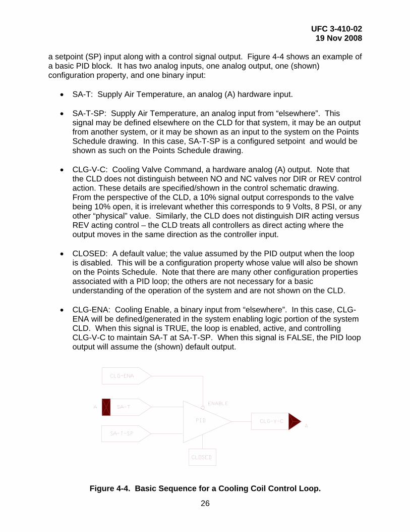
26
a setpoint (SP) input along with a control signal output. Figure 4-4 shows an example of a basic PID block. It has two analog inputs, one analog output, one (shown) configuration property, and one binary input:
• SA-T: Supply Air Temperature, an analog (A) hardware input. • SA-T-SP: Supply Air Temperature, an analog input from “elsewhere”. This
signal may be defined elsewhere on the CLD for that system, it may be an output from another system, or it may be shown as an input to the system on the Points Schedule drawing. In this case, SA-T-SP is a configured setpoint and would be shown as such on the Points Schedule drawing.
• CLG-V-C: Cooling Valve Command, a hardware analog (A) output. Note that
the CLD does not distinguish between NO and NC valves nor DIR or REV control action. These details are specified/shown in the control schematic drawing. From the perspective of the CLD, a 10% signal output corresponds to the valve being 10% open, it is irrelevant whether this corresponds to 9 Volts, 8 PSI, or any other “physical” value. Similarly, the CLD does not distinguish DIR acting versus REV acting control – the CLD treats all controllers as direct acting where the output moves in the same direction as the controller input.
• CLOSED: A default value; the value assumed by the PID output when the loop
is disabled. This will be a configuration property whose value will also be shown on the Points Schedule. Note that there are many other configuration properties associated with a PID loop; the others are not necessary for a basic understanding of the operation of the system and are not shown on the CLD.
• CLG-ENA: Cooling Enable, a binary input from “elsewhere”. In this case, CLG-
ENA will be defined/generated in the system enabling logic portion of the system CLD. When this signal is TRUE, the loop is enabled, active, and controlling CLG-V-C to maintain SA-T at SA-T-SP. When this signal is FALSE, the PID loop output will assume the (shown) default output.
Figure 4-4. Basic Sequence for a Cooling Coil Control Loop.

UFC 3-410-02 19 Nov 2008
27
4-3.2 System enabling logic Figure 4-5 shows enabling logic at the system level, including the logic that enables the cooling loop (CLG-ENA) as shown in the lower right hand corner of Figure 4-5. This block has multiple inputs and outputs:
• SF-S: Supply Fan Status; a hardware binary (B) input proof that the supply fan is running. This can be from a current sensing relay, flow switch, or feedback from a variable frequency drive unit; the exact mechanism is unimportant.
• RF-S: Return Fan Status; a hardware binary (B) input. • FAN-DIS: Fan Disable; a binary signal from the “Alarms and Shutdown” block;
this is TRUE when an alarm occurs and the air handling unit should be shutdown.
• SYS-OCC: System Occupancy; a network binary signal from the system
scheduler providing system occupancy status. • BLDG-T-LL-SP: Building Temperature Low Limit SetPoint; a configured analog
input. This is the night-setback temperature. • BLDG-T: Building Temperature; a hardware analog (A) input from the night stat • FAN-FAIL: A binary signal (to the “Alarms and Shutdown” block diagram)
indicating a fan has failed (not running when it should be). • SYS-ENA (and SF-SS): A binary signal indicating that the system is enabled and
running. Note this same signal is also used as a hardware binary (B) output to the fan. This signal is true whenever the system is commanded to be on (either due to occupancy or night stat) and the system is not being shutdown due to an alarm condition.
• CLG-ENA (and ECO-ENA): A binary enable signal to the cooling block and
economizer blocks, respectively, enabling those loops. This signal is enabled whenever the SYS-ENA is TRUE and the occupancy is OCCUPIED or WARM UP / COOL DOWN.
• MINOA-ENA: A binary enable signal to the MIN-OA control block. This signal is
enabled whenever the SYS-ENA is TRUE and the occupancy is OCCUPIED.

UFC 3-410-02 19 Nov 2008
28
Figure 4-5. System Enabling Logic.
4-3.3 Alarms and shutdown CLD Figure 4-6 shows logic used to shut the system down in case of an alarm condition. It has multiple inputs and outputs:
• PH-T-LL: Preheat Temperature Low Limit; a hardware binary (B) input from the freeze stat. This will be from a contact that closes upon a drop in temperature below the freeze stat setpoint. Therefore this signal is true when the freeze stat “trips”. Note there is an implied setpoint here: the freeze stat trip setting. This is not shown in the CLD because this as a hardware configuration setting (something that gets adjusted via setscrew at the freezestat) and is shown in the Points Schedule. Note that the example CLD shows a freeze stat for the preheat
UFC 3-410-02 19 Nov 2008
29
coil. In the absence of a preheat coil the freeze stat would be in a different location (such as at the cooling coil).
• SA-P-HL: Supply Air Pressure High Limit; a hardware binary (B) input from the
duct high pressure limit safety switch located at the outlet of the fan. This input is from a contact that closes upon a rise in pressure above the pressure switch setpoint. As with the PH-T-LL the SA-P-HL setpoint is implied in the CLD and its setting is shown in the Points Schedule. Note that while the example CLD shows a SA-P-HL this only applies to a VAV air handler and (ordinarily) should not be shown in a non-VAV system.
• SA-SMK and RA-SMK: Supply (Return) Air Smoke; hardware binary (B) inputs
from the smoke detectors. • FAN-FAIL: A binary signal from the System Enabling Logic indicating fan failure. • RST-BUT: Reset Button; a hardware binary (B) input (to the DDC control logic)
from a pushbutton located at the AHU (or AHU control panel). This signal clears the system failure and resulting shutdown due to any of the above alarms.
• FAN-DIS: Fan Disable: A binary (B) signal which goes to the System Enabling
Logic to disable the system. The CLD shows one other component, a set/reset (S/R) Latch used to “remember” the system failure until the failure is cleared via the RST-BUT input. The designer needs to specify the setpoints for the PH-T-LL and SA-P-HL alarms. Note that the alarm conditions are dealt with directly by the sequence running in the DDC Hardware. As a general rule, alarm conditions must be dealt with in the control system sequence of operation. While an alarm should be sent to the M&C server, the sequence must place the system in a “safe” mode and not rely on operator intervention.

UFC 3-410-02 19 Nov 2008
30
Figure 4-6. Alarms and Shutdown CLD.
4-4 CONTROL LOOPS
4-4.1 Preheat coil control loop A minimum amount of outside air (OA) must always be used in HVAC systems. In cold climates preheating the OA avoids the freeze-up of coils and raises the temperature of the OA before using it in the system. Preheated OA is usually mixed in the return air plenum with a setpoint between 40° and 55°F depending on the application. For example, a 40°F setpoint might be used when there is a downstream coil to further condition the air while a 55°F setpoint might be used when there is no downstream coil. Figure 4-7 shows the preheat coil temperature loop schematic, and Figure 4-8 shows the CLD for preheat coil control. Designer selections for this loop include: (1) Preheat coil discharge air temperature setpoint (2) Preheat coil temperature low limit (PH-T-LL) (referred to as the Freeze stat) setpoint, (3) Valve size (Cv), (4) valve shutoff pressure/force, and (5) Control action of the controller. Note that the freeze stat is shown on the Preheat Coil Loop Control Schematic because that is physically where it is located and is shown on the Alarms and Shutdown CLD (not the Preheat Coil CLD) because that is where it is logically located.

UFC 3-410-02 19 Nov 2008
31
Figure 4-7. Preheat Coil Control Schematic.
Figure 4-8. Preheat Coil CLD.
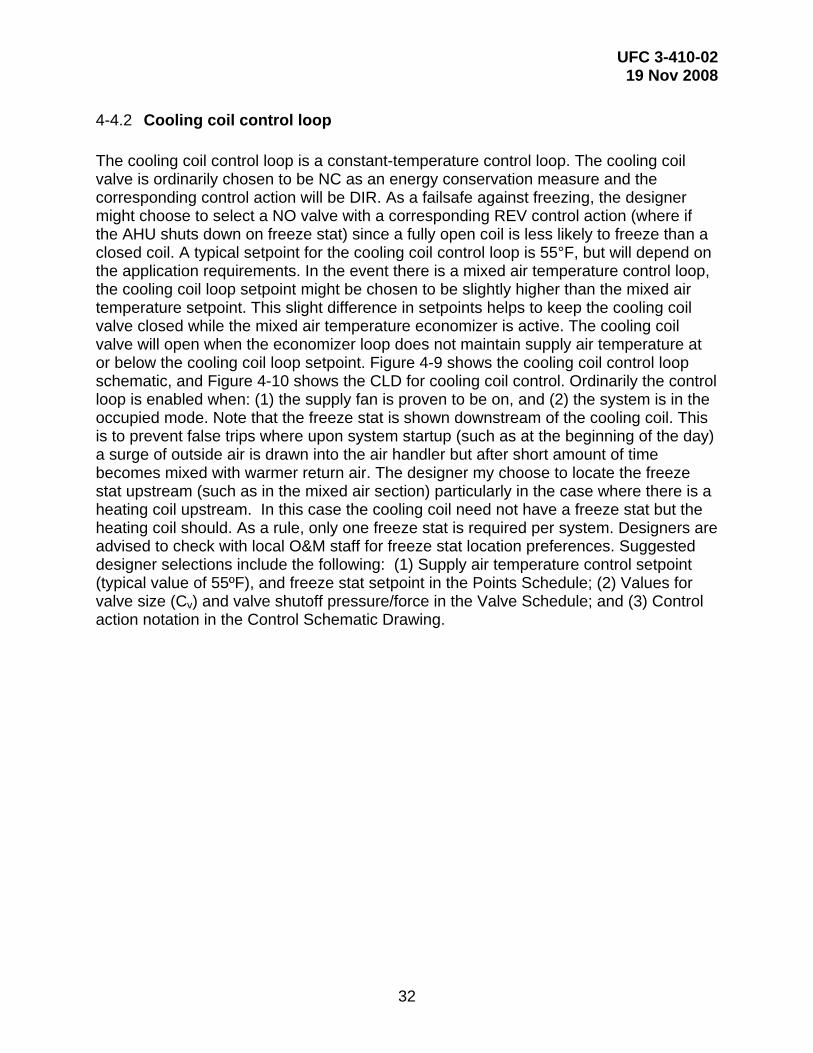
UFC 3-410-02 19 Nov 2008
32
4-4.2 Cooling coil control loop The cooling coil control loop is a constant-temperature control loop. The cooling coil valve is ordinarily chosen to be NC as an energy conservation measure and the corresponding control action will be DIR. As a failsafe against freezing, the designer might choose to select a NO valve with a corresponding REV control action (where if the AHU shuts down on freeze stat) since a fully open coil is less likely to freeze than a closed coil. A typical setpoint for the cooling coil control loop is 55°F, but will depend on the application requirements. In the event there is a mixed air temperature control loop, the cooling coil loop setpoint might be chosen to be slightly higher than the mixed air temperature setpoint. This slight difference in setpoints helps to keep the cooling coil valve closed while the mixed air temperature economizer is active. The cooling coil valve will open when the economizer loop does not maintain supply air temperature at or below the cooling coil loop setpoint. Figure 4-9 shows the cooling coil control loop schematic, and Figure 4-10 shows the CLD for cooling coil control. Ordinarily the control loop is enabled when: (1) the supply fan is proven to be on, and (2) the system is in the occupied mode. Note that the freeze stat is shown downstream of the cooling coil. This is to prevent false trips where upon system startup (such as at the beginning of the day) a surge of outside air is drawn into the air handler but after short amount of time becomes mixed with warmer return air. The designer my choose to locate the freeze stat upstream (such as in the mixed air section) particularly in the case where there is a heating coil upstream. In this case the cooling coil need not have a freeze stat but the heating coil should. As a rule, only one freeze stat is required per system. Designers are advised to check with local O&M staff for freeze stat location preferences. Suggested designer selections include the following: (1) Supply air temperature control setpoint (typical value of 55ºF), and freeze stat setpoint in the Points Schedule; (2) Values for valve size (Cv) and valve shutoff pressure/force in the Valve Schedule; and (3) Control action notation in the Control Schematic Drawing.

UFC 3-410-02 19 Nov 2008
33
Figure 4-9. Cooling Coil Control Schematic.
Figure 4-10. Cooling Coil CLD.
4-4.3 Heating coil control loop with setpoint reset This control loop involves the control setpoint being adjusted (reset) based on a system variable (usually outside air temperature). Typical applications are (1) Heating hot water temperature (hydronic) and (2) Heating coil discharge air temperature.

UFC 3-410-02 19 Nov 2008
34
A reset schedule defines the relationship between outside air temperature and setpoint temperature. Figure 4-11 shows an example of setpoint reset control, with the following characteristics: (1) heating coil discharge air temperatures of 120°F at 0°F outside air and below; (2) 90°F at 60°F outside air and above.
Figure 4-11. Typical Setpoint Reset Schedule for Heating Coil Air Temperature.
Figure 4-12 shows the heating coil with outside air reset control loop schematic. Suggested designer selections include the following: (1) Values for setpoint and freeze stat setpoint in the Points Schedule; (2) Reset Schedule, if setpoint reset is used; (3) Values for valve size (Cv) and valve shutoff pressure/force in the Valve Schedule; and (4) Control action notation in the Control Schematic Drawing.
0 60
90
120
HEATING COILDISCHARGE AIR SETPOINT °F
OUTSIDE AIR TEMPERATURE °F
0 60
90
120
HEATING COILDISCHARGE AIR SETPOINT °F
OUTSIDE AIR TEMPERATURE °F

UFC 3-410-02 19 Nov 2008
35
Figure 4-12. Heating Coil with Outside Air Reset Control Schematic.
4-4.4 Mixed air temperature control with economizer An economizer functions as a switch to introduce outside air for “free cooling”. When the economizer is “on”, the mixed air temperature control loop DDC controller modulates the outside, return, and relief dampers. Modulation of the outside and return dampers regulates mixed air temperature (MA-T) to its specified setpoint while modulation of the relief damper serves to exhaust the additional outside air delivered to the building/spaces. When the economizer is “off” the economizer outside air damper is closed.

UFC 3-410-02 19 Nov 2008
36
Figure 4-13. Economizer/Mixed Air Temperature Control Schematic.
4-4.4.1 OA-Only dry bulb economizer Although there are many ways to perform the economizer on/off decision, a control system that uses only an outside air dry bulb sensor is recommended based on its simplicity and long term reliability as compared to other methods.

UFC 3-410-02 19 Nov 2008
37
Figure 4-13 shows the OA-only dry bulb economizer control loop. It uses an OA dry bulb sensor and DDC controller to make the economizer on/off decision. When the Economizer is on, the controller sends a mixed air damper command (MA-D-C) to modulate the relief, return, and outside air dampers. When the economizer if off, the DDC moves the three dampers to their failsafe positions. Minimum outside air quantity is maintained by a separate control loop. The return air temperature sensor shown in figure 4-13 is optional and would be used only for temperature monitoring purposes. Figure 4-14 shows the CLD for the OA-only dry bulb economizer. As described previously, the System Enabling Logic provides the SYS-ENA signal (based on occupied mode and fan proof). When the outside air temperature is less than the economizer high limit setpoint (ECO-HL-SP) a ‘true’ output is generated by the comparator (COMP). Similarly, when outside air temperature is greater than the economizer low limit setpoint (ECO-LL-SP) a true output is generated by the other comparator (COMP). When all three conditions are true the AND gate generates a true output enabling the MA-T PID loop. When the PID is not enabled the default output closes the OA economizer damper.
Figure 4-14. OA-Only Dry Bulb Economizer CLD.

UFC 3-410-02 19 Nov 2008
38
4-4.4.2 OA-Only dry bulb economizer designer selections The designer must select the economizer high limit setpoint (ECO-HL-SP), the low limit temperature setpoint (ECO-LL-SP), and the mixed air temperature setpoint (MA-T-SP).
4-4.4.2.1 Economizer high limit setpoint selection Economizer high limit setpoint (ECO-HL-SP) is the dry bulb temperature below which the OA-only economizer turns “on”. The objective is to select it low enough so that the economizer turns on when the OA enthalpy is lower than the return air enthalpy, thus achieving free cooling. Since neither the return air enthalpy nor outside air enthalpy are being measured, assumptions must be made. Outside air enthalpy can be estimated based on the outside air dry bulb temperature using (local) average weather data. The ECO-HL-SP is then selected based on this estimation. Due to the assumptions made a margin of safety is then applied to the selection of ECO-HL-SP. Figure 4-15 illustrates selection of the OA-only economizer setpoint for Greenville, NC:
1. Plot a constant enthalpy line through the return air design dry bulb temperature & relative humidity (A-B). In this example, 78°F and 50% RH. Caution: Give careful consideration to the return air condition. For example, if you follow this procedure for 78°F and 50% RH condition but the actual condition is 72°F and 50% RH, the economizer (on average) will turn on about 4°F or 5°F sooner than it should, resulting in wasted mechanical cooling energy.
2. Plot a weather line (C-D) for the worst case month, in this case July, using the
midpoint of each OA dry bulb bin and corresponding mean coincident OA wet bulb. To help select the worst case month, you may choose to plot the average weather line for two or three summer months and then proceed to step 3. Wet bulb and dry bulb weather data is available through UFC 3-400-02 "Design: Engineering Weather Data" which references a data download site at http://www.afccc.af.mil.
3. Draw a vertical line down from the intersection of lines A-B and C-D to the dry
bulb axis. This is Point E. (If you plotted multiple average weather lines, draw the vertical line down from the month that places Point E furthest to the left.)
4. For the OA-only economizer, the economizer high limit setpoint (ECO-HL-SP) is
point E, or 67°F. Again, note the additional caution in step 1.

UFC 3-410-02 19 Nov 2008
39
Figure 4-15. OA-Only Economizer Setpoint Selection Example for Greenville, NC.

UFC 3-410-02 19 Nov 2008
40
Figure 4-16. Greenville SC Weather Data for OA-Only Economizer Setpoint
Selection Example.
4-4.4.2.2 Low limit temperature setpoint selection Economizer low limit setpoint (ECO-LL-SP) is the dry bulb temperature below which the OA-only economizer turns ‘off’ when the OA temperature is cool/cold (e.g. 50ºF). As a practical matter, while the economizer is ‘on’, the mixed air control loop will modulate the dampers to maintain the mixed air setpoint. Therefore this low limit function is theoretically not needed, but it can help prevent nuisance tripping of the freeze stat and can also help stabilize the minimum outside air flow control loop by eliminating interaction between these two competing airflow paths. Selection of the ideal setpoint selection would require modeling to identify the heat/cool balance point of the building where, below the balance point, the building only needs heating. Modeling can be expensive and therefore not practical. An estimate of the ECO-LL-SP (balance point) is acceptable, usually 50ºF. Applications with high internal cooling loads may benefit from a lower setting.
4-4.4.2.3 Mixed air temperature setpoint selection The mixed air temperature setpoint (MA-T-SP) should be selected to be the same as the cooling coil control loop discharge air setpoint (CC-DA-T-SP), typically 55°F, or 1°F to 2°F less than CC-DT-SP. A lesser setpoint helps to reduce or eliminate mechanical cooling while the economizer is ‘on’.

UFC 3-410-02 19 Nov 2008
41
4-4.4.3 OA/RA dry bulb economizer The OA/RA dry bulb economizer is a refinement of the OA-only economizer in that it takes into account the return air condition by sensing return air dry bulb. This economizer should be used with caution but can be beneficial where the return air condition is not constant such as in variable load and/or variable occupancy applications. More importantly, proper operation is highly dependent upon seasonal changes in space temperature setpoints in that heating mode space setpoints must be lower than cooling mode space setpoints. This is further discussed as part of the Condition 2 setpoint selection. Figure 4-13 and Figure 4-17 illustrate the OA/RA dry bulb economizer. Unlike the OA-only economizer the OA/RA economizer uses both the outside and return air temperature sensor measurements. It operates when both of two temperature conditions are met:
1. Condition 1: The difference between return and outdoor air temperatures (RA-T and OA-T, respectively) is sufficient to use OA for free cooling. Specifically, RA-T minus OA-T is greater than the economizer differential setpoint (ECO-DIFF-SP)
2. Condition 2: RA-T indicates that there is a cooling load. Specifically, RA-T is
greater than the ECO-HL-SP. Note that RA-T is not the only mechanism by which the economizer can determine if there is a cooling load. The designer may choose an alternate mechanism such as the status of the cooling coil valve position (where if it is not closed, Condition 2 is met).
In addition, as described previously, the economizer enable (ECO-ENA) signal must be ‘true’. This signal is generated by the System Enabling Logic (when the system is in occupied mode and supply fan proven ‘on’).
UFC 3-410-02 19 Nov 2008
42
MINUS
Figure 4-17. Mixed Air Temperature Control with RA/OA Activated Economizer
CLD.
4-4.4.4 OA/RA dry bulb economizer designer selections The designer must select the ECO-DIFF-SP and the ECO-HL-SP.
4-4.4.4.1 OA/RA economizer differential setpoint selection Selection of the switching ‘Condition 1’ ECO-DIFF-SP is based on annual average (wet bulb) weather data which takes enthalpy into account, thereby optimizing the dry bulb economizer’s on/off decision. In summary, the designer uses a psychrometric chart and BIN weather data to correlate OA enthalpy to OA dry bulb along with an assumed RA condition (%RH and dry bulb) to correlate RA enthalpy to RA dry bulb. This results in a measure of OA and RA dry bulb temperatures that, in effect, provides for an enthalpy-based economizer decision. Figure 4-18 illustrates selection of the OA/RA economizer Condition 1 setpoint (ECO-DIFF-SP) for Greenville, NC using weather data shown in Figure 4-16:

UFC 3-410-02 19 Nov 2008
43
1. Plot a constant enthalpy line through the return air design temperature & relative humidity (A-B). In this example, 78°F and 50% RH.
2. Plot the average weather line (C-D). Use the midpoint of each OA dry bulb bin
and corresponding mean coincident OA wet bulb from TM-5-785. 3. Draw a vertical line down from the intersection of lines A-B and C-D. This is point
E. 4. Draw vertical line (G) down from constant enthalpy line return air condition to dry
bulb temperature. 5. The OA/RA economizer ECO-DIFF-SP is the difference between point E and
point G. 6.
Figure 4-18. OA/RA Economizer Differential Setpoint Selection.

UFC 3-410-02 19 Nov 2008
44
Figure 4-19. Greenville SC Weather Data for OA/RA Economizer Setpoint
Selection Example.
4-4.4.4.2 OA/RA economizer high limit setpoint selection Selection of the switching ‘Condition 2’ ECO-DIFF-SP, and thus proper operation of this economizer, is premised on the assumption that the return air temperature will vary based on the need for heating or cooling and, to a lesser extent, based on load changes. In other words, there must be a seasonal swing in the return air temperature. This swing can be achieved by defining and implementing zone/space heating and cooling thermostat setpoints (i.e. 68°F heating and 78°F cooling). If this is not desirable or achievable, the OA/RA dry bulb economizer is not recommended. With a heating mode setpoint of 68°F and and a cooling mode setpoint of 78°F, the midpoint is 73°F. To account for return air heat pickup from lights and other sources, add 2°F to this midpoint. The ECO-HL-SP setpoint is then 75°F.
4-4.4.4.3 Mixed air temperature setpoint selection The mixed air temperature setpoint (MA-T-SP) should be selected to be the same as the cooling coil control loop discharge air setpoint (CC-DA-T-SP) (typically 55°F) or 1°F to 2°F less than CC-DA-T-SP. This lower setpoint helps to reduce or eliminate mechanical cooling while the economizer is ‘on’.

UFC 3-410-02 19 Nov 2008
45
4-4.5 Outside air flow control This section describes the three preferred methods that may be used to accomplish outside air flow control:
1) Two-Position Damper 2) Flow Control 3) Demand Controlled Ventilation
In each case, a separate/dedicated ventilation outside air duct should be specified. A dedicated duct provides for a more accurate setting and better control of the outside air flow. 100% outside air systems and systems that do not contain an economizer do not require this separate/dedicated duct. The control system design must be accomplished in accordance with ASHRAE Standard 62, “Ventilation for Acceptable Indoor Air Quality”, which describes how to provide indoor air quality that will be acceptable to human occupants and is intended to minimize the potential for adverse health effects. Standard 62 also contains guidance on managing sources of contamination, controlling indoor humidity, and filtration of the building air.
4-4.5.1 Ventilation air versus make-up air Design of the outside air flow control loop and the specified minimum outside air (MINOA) flow quantity must take into account two basic considerations;
1) Ventilation air for building occupants, and 2) Make-up air required to offset building exhaust and to provide pressurization for exfiltration flow
The MINOA quantity selected by the designer must be sufficient to meet the ventilation air flow requirements as defined in ASHRAE Standard 62. In addition, the minimum outside air quantity must be sufficient to provide make-up air for all sources of exhaust flow (Exh Flow) from the areas served by the air handler and to provide for a degree of building pressurization by creating exfiltration flow (Exf Flow). The larger of these two outside air quantities should be selected and specified as the MINOA quantity. In summary: If Ventilation Air Flow > (Exh Flow + Exf Flow), then: MINOA = Ventilation Air Flow If Ventilation Air Flow < (Exh Flow + Exf Flow), then MINOA = Exh Flow + Exf Flow The exfiltration flow component is intended to help ensure that that the MINOA flow exceeds the building exhaust flow. This in turn helps to create a positive pressure in the zones/spaces served by the air handler. Exact calculation of the exfiltration flow that is required to create positive building pressure is a non-exact science due to uncertainty in inter-zonal flows and year round variations in wind-induced pressure on the external

UFC 3-410-02 19 Nov 2008
46
surfaces of the building. It can be estimated using special computer programs, the ASHRAE crack method, or ASHRAE air exchange method. Alternatively, the exfiltration flow can be estimated to be a small fraction (5 to 10%) of the total design flow.
4-4.5.2 Two-position damper This scheme applies to constant volume systems such as multizone and single zone air handlers. It can also be used in 100% outside air systems where there is only a single OA duct. Figure 4-20 shows a CLD for minimum OA damper control using a two-position damper.
Figure 4-20. Minimum OA Using Two-Position Damper CLD.
4-4.5.3 Flow control This scheme applies to variable air volume systems. This approach helps to ensure that the specified outside air quantity is supplied to the system/zones as supply fan capacity modulates with changes in VAV terminal unit flows. A minimum outside air flow (MINOA-F) sensor senses flow in the MINOA duct and is controlled to the specified setpoint through modulation of the MINOA damper using a PID controller. Figure 4-21 shows a CLD for MINOA flow control using fixed OA flow.

UFC 3-410-02 19 Nov 2008
47
Figure 4-21. Minimum OA Flow CLD.
4-4.5.4 Demand controlled ventilation A demand controlled ventilation (DCV) strategy adjusts ventilation air to a building or zone to meet occupant needs and to provide for odor control. It can also save energy by minimizing ventilation loads. ASHRAE Standard 62.1-2004 describes adjustment of the HVAC system to “reset the design outdoor air intake flow and/or space or zone airflow as operating conditions change.” Standard 62.1-2004 lists examples of dynamic reset strategies including reset based on occupancy such as an occupancy schedule, occupancy sensors, or carbon dioxide (CO2) sensors. CO2 based DCV uses CO2 sensor(s) to predict the demand where contaminant levels result primarily from people and occupancy varies significantly (barracks, mess halls, conference facilities, gyms, and auditoriums). Leadership in Energy and Environmental Design (LEED) points can be awarded for use of a demand control strategy.
4-4.5.4.1 Demand controlled ventilation design The design of a CO2-based DCV control strategy should be in accordance with the standards and procedures described in ASHRAE Standard 62.1. Standard 62.1-2004 requires that spaces with a design occupancy density greater than 100 people per 1000 ft2 incorporate DCV in the HVAC design (i.e. lecture halls, auditoriums, lobbies). Standard 62.1-2004 also includes guidance on maintenance that the designer should consider and include in the project specifications.

UFC 3-410-02 19 Nov 2008
48
The DCV strategy should adjust the outside air (OA) flow quantity based on the sensed CO2 concentration while also limiting the outside air flow quantity (to a minimum and maximum quantity). The DCV control loop must be designed and specified such that the system modulates between the upper limit of “minimum OA” and lower limit of “minimum OA.” The HVAC system must be sized to accommodate the ventilation load. The use of a DCV strategy applies to variable air and constant volume systems. The OA flow damper should be located in a dedicated minimum OA flow duct and modulated to control the OA flow quantity. Flow control is accomplished by simple damper positioning in a constant volume system and by an air flow measurement station (AFMS) in a VAV system. Two-position dampers are unacceptable in a VAV system.
4-4.6 Variable air volume control loops A variable air volume (VAV) system has the following unique characteristics:
• The air-handling unit (AHU) serves multiple zones with a single duct that delivers cool air. Sometimes the AHU will have a small preheat coil.
• Each zone has a VAV box (terminal unit) for temperature control. Each VAV box
has a thermostat. VAV box dampers modulate for cooling. Heating may be provided by a reheat coil or electric resistance heating element inside the VAV box with the dampers at a minimum airflow position.
• VAV boxes open and close causing total air volume to vary. • The AHU fan capacity varies to the keep the duct pressure constant.
4-4.6.1 Supply duct static pressure control loop In a supply duct static pressure control loop, the supply fan capacity modulates to maintain a constant duct static pressure while the VAV boxes are opening and closing. Each VAV box needs a minimum amount of static pressure to operate properly and to deliver the required amount of air to its zone. There are two methods of supply fan capacity control: (1) using a variable speed fan (recommended) and (2) inlet guide vanes. Figure 4-22 shows the supply duct static pressure control loop schematic while Figure 4-23 shows the CLD for supply duct static pressure control.

UFC 3-410-02 19 Nov 2008
49
Figure 4-22. Supply Duct Static Pressure Control Schematic.
Figure 4-23. Supply Duct Static Pressure CLD.

UFC 3-410-02 19 Nov 2008
50
Suggested designer selections include the following: (1) Value for supply duct static pressure setpoint (SA-P-SP) in the Points Schedule (typically 1 inch of water column (iwc)); (2) Value for duct static (differential) pressure sensor range (typically 0 to 2.5 iwc); (3) Value for duct static high-limit setpoint based on duct pressure class; and (4) Control action notation in the Control Schematic Drawing.
4-4.6.2 Supply duct static pressure control loop with setpoint reset
In accordance with ASHRAE standard 90.1, a variation on the basic supply duct static pressure loop is where the setpoint is adjusted based on VAV box demand. The commanded position of each VAV box damper is used to determine demand.
Figure 4-24. Supply Duct Static Pressure Setpoint Reset.
Figure 4-25. Supply Duct Static Pressure Setpoint Reset, Setpoint Calculation.

UFC 3-410-02 19 Nov 2008
51
Figure 4-26. Supply Duct Static Pressure Setpoint Reset, Ramp-up / Ramp-down.
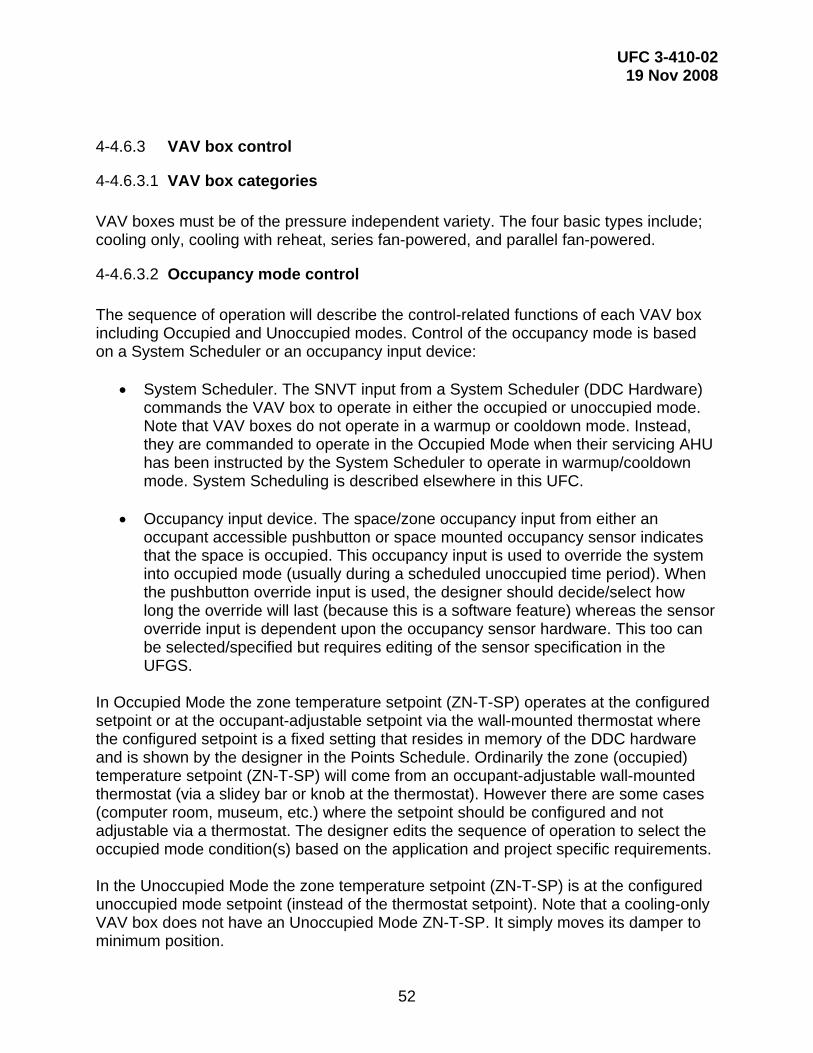
UFC 3-410-02 19 Nov 2008
52
4-4.6.3 VAV box control
4-4.6.3.1 VAV box categories VAV boxes must be of the pressure independent variety. The four basic types include; cooling only, cooling with reheat, series fan-powered, and parallel fan-powered.
4-4.6.3.2 Occupancy mode control The sequence of operation will describe the control-related functions of each VAV box including Occupied and Unoccupied modes. Control of the occupancy mode is based on a System Scheduler or an occupancy input device:
• System Scheduler. The SNVT input from a System Scheduler (DDC Hardware) commands the VAV box to operate in either the occupied or unoccupied mode. Note that VAV boxes do not operate in a warmup or cooldown mode. Instead, they are commanded to operate in the Occupied Mode when their servicing AHU has been instructed by the System Scheduler to operate in warmup/cooldown mode. System Scheduling is described elsewhere in this UFC.
• Occupancy input device. The space/zone occupancy input from either an
occupant accessible pushbutton or space mounted occupancy sensor indicates that the space is occupied. This occupancy input is used to override the system into occupied mode (usually during a scheduled unoccupied time period). When the pushbutton override input is used, the designer should decide/select how long the override will last (because this is a software feature) whereas the sensor override input is dependent upon the occupancy sensor hardware. This too can be selected/specified but requires editing of the sensor specification in the UFGS.
In Occupied Mode the zone temperature setpoint (ZN-T-SP) operates at the configured setpoint or at the occupant-adjustable setpoint via the wall-mounted thermostat where the configured setpoint is a fixed setting that resides in memory of the DDC hardware and is shown by the designer in the Points Schedule. Ordinarily the zone (occupied) temperature setpoint (ZN-T-SP) will come from an occupant-adjustable wall-mounted thermostat (via a slidey bar or knob at the thermostat). However there are some cases (computer room, museum, etc.) where the setpoint should be configured and not adjustable via a thermostat. The designer edits the sequence of operation to select the occupied mode condition(s) based on the application and project specific requirements. In the Unoccupied Mode the zone temperature setpoint (ZN-T-SP) is at the configured unoccupied mode setpoint (instead of the thermostat setpoint). Note that a cooling-only VAV box does not have an Unoccupied Mode ZN-T-SP. It simply moves its damper to minimum position.

UFC 3-410-02 19 Nov 2008
53
Sequencing diagrams should be included to illustrate the zone temperatures at which VAV box devices such as valves, dampers, fans, and heating elements turn on and off and/or open and close.
4-4.6.3.3 VAV box control - designer selections Most designer selections will be shown in the Thermostat and Occupancy Sensor Schedule drawing as shown in Figure 5-3. Some settings will be shown in the Points Schedule drawing. Designer selections for VAV box control include the following:
(1) Thermostat location (particularly room number) to be shown in the schedule, (2) Whether or not the temperature setpoint is to be adjustable at the thermostat, (3) Occupied and unoccupied mode setpoints, (4) Unoccupied mode override (occupant accessible push button), (5) Unoccupied mode override (occupancy sensor), (6) Valve size (Cv) in the case of a box containing a coil, and (7) VAV box sequencing including a deadband between heating and cooling modes and the minimum and maximum airflow setpoints. Ordinarily, the minimum and maximum flow setpoint quantities are shown in a separate mechanical system drawing, not a control drawing.
4-4.6.4 Return fan control loop A return fan in a VAV system is inherently difficult to control. Therefore, designers should avoid them where possible by using short or large return ducts and plenum instead of ducted returns. A return fan helps to ensure proper air distribution and may be required if the return air duct section pressure drop (between the zone and the relief damper) is excessive or if the supply fan inlet head will prevent positive pressure from being created at the air handler relief. Excessive return duct pressure drop can result in the following: (1) Over-pressurization of zone and excessive exfiltration as the supply air seeks an exit path out of the zone; (2) Inadequate supply air flow at the design condition due to zone and return duct flow resistance; (3) Air being drawn in through the AHU relief duct (not exhausted); or (4) The need for a return fan.
4-4.6.4.1 Return fan control techniques
4-5.8.3.1.1 Flow matching Flow matching is accomplished by measuring the supply and return air duct flow rates using airflow measurement devices/arrays and controlling the return duct flow by modulating the return fan capacity.
4-5.8.3.1.2 Direct building pressurization

UFC 3-410-02 19 Nov 2008
54
Direct building pressurization is accomplished by measuring the building/space pressure using a differential pressure sensor (referenced to outdoors) and modulating the capacity of the return fan.
4-5.8.3.1.3 Fan matching Fan matching is accomplished by sending a control signal to the return fan identical to that used to modulate the capacity of the supply fan. Ordinarily, the signal sent to the return fan is offset or characterized in some fashion so that the return duct flow is less than the supply duct flow.
4-4.6.4.2 Flow matching return fan control loop Of the three primary techniques for controlling a return fan in a VAV system, flow matching is recommended. Flow matching uses air flow measurement devices in the supply and return air ducts and the control loop maintains a constant flow difference between the supply and return air ducts. When more air is supplied than returned, this tends to pressurize the building or zones. Matching air flows also helps ensure proper air distribution through the air handler outside air intake and relief. Figure 4-27 shows a return fan flow control loop schematic, and Figure 4-28 shows the CLD.

UFC 3-410-02 19 Nov 2008
55
Figure 4-27. Return Fan Flow Control Schematic.

UFC 3-410-02 19 Nov 2008
56
Figure 4-28. Return Fan Flow CLD.
4-4.6.4.3 Flow difference setpoint (F-DIFF-SP) selection The designer must select the Flow Difference Setpoint (F-DIFF-SP) for the flow matching control loop:
F-DIFF-SP = Flowexh + Flowexf Eq. 4-1
Where: Flowexh = Zone exhaust flow, cfm or L/s Flowexf = Zone exfiltration flow, cfm or L/s Figure 4-29 illustrates these flows. Flowexh is the total of all zone exhaust fan flows. Flowexf is selected to create a degree of pressurization in the zone by forcing air to exfiltrate from the zone. Theoretically, zone pressurization will occur with only the slightest amount of exfiltration flow but, due to limitations in flow sensor and controller accuracy, Flowexf should be selected as 7 to 10 percent of the design supply flow. This helps ensure that supply flow will be greater than return flow. In addition, depending on the need in the application to ensure pressurization, the designer might chose to increase Flowexf. As rules of thumb: Flowexf = 10% of design flow (for tight buildings) and 20% of design flow (for drafty buildings). The following cautions apply to these “rules of thumb”:
1. The zone(s) on the windward side of the building may be overcome by external wind pressure on the building surface. A 17 mph wind induces an external velocity pressure on the face of the building of approximately 0.1 in. wc (25 Pa) and can result in air infiltration. A larger bias flow may not counteract external wind pressure (i.e. the excess bias flow may exfiltrate out of the downwind side of building or be exhausted by exhaust fans or migrate to other zones/air handlers).

UFC 3-410-02 19 Nov 2008
57
Figure 4-29. Air Flows in a Return Fan System.
4-4.6.4.4 Minimum OA (MINOA) quantity selection The designer should coordinate the return fan Flow Difference Setpoint (F-DIFF-SP) with the minimum outside air flow selection. The minimum outside air quantity (MINOA) used in conjunction with the F-DIFF-SP setting is determined by one of the following: MINOA = Flowvent if Flowvent > (Flowexf + Flowexh) Eq. 4-2
MINOA = Flowexf+exh if Flowvent < (Flowexf + Flowexh) Eq. 4-3
Where:
Flowvent = Ventilation air flow (based on ASHRAE Standard 62, “Ventilation for Acceptable Indoor Air Quality”). Flowexh = Zone exhaust flow, cfm or L/s (total of all exhaust fans in the zone) Flowexf = Zone exfiltration flow, cfm or L/s
(Note: If a CO2-based demand controlled ventilation control strategy is to be used the F-DIFF-SP and MINOA flow selections must be coordinated. The correct MINOA selection helps to ensure proper air distribution thru AHU by complementing the F-DIFF-SP value. The MINOA selection also applies to non-return fan systems.
OA MA
RA(relief)
FlowRA
FlowSA
ZONE
FlowEXF
FlowEXH
OA MA
RA(relief)
FlowRA
FlowSA
ZONE
FlowEXF
FlowEXH

UFC 3-410-02 19 Nov 2008
58
Suggested designer selections, all to be shown in the Points Schedule, include the following: (1) Value of F-DIFF-SP, in L/s (cfm); (2) Value of return air duct airflow measurement array (AFMA) range, from 0 to a defined maximum value in L/s (cfm); (3) Value of supply air duct AFMA range, from 0 to a defined maximum value in L/s (cfm); and (4) Value of the minimum OA quantity in L/s (cfm).
4-4.7 Variable speed pump control 4-5.7.1 Variable speed pump control system design A variable frequency drive (VFD) can provide significant energy savings realized from reduced pump horsepower as flow rate is decreased to match decreased load. Energy is saved at a cubed rate where even a small reduction in the pump's speed (such as 20%) can translate into a large energy savings (such as 50%). The greater the average annual load variation from maximum design conditions, the greater the energy savings potential with variable speed pumping. Variable frequency drives can also reduce maintenance (in the pump seals).
Figure 4-30 shows an example control schematic for a primary/secondary piping system where the secondary pump VFD is modulated by the direct digital controller (DDC) based on the piping system differential pressure in the downstream secondary piping loop.
Figure 4-30 shows that the piping system should have at least one 3-way valve or a bypass pipe. Locating the valve or bypass at or near the end of the piping run is not critical but helps to keep the chilled water loop cool and thus avoids a warm water surge at the chiller. A balancing valve in the 3-way valve bypass, set equal to the head loss across the coil circuit, can help with temperature control performance of the 3-way valve and can be used to provide adjustment of the minimum system flow. Adjustment of minimum system flow is not important in the secondary of a primary/secondary system but may be necessary where the variable speed pump loop consists of only a primary (no secondary) and the chiller (or boiler) has a minimum flow rating that must be observed. The chilled water pressure sensor (CWS-P) must be at or near the end of the piping run for sensing the differential between the supply and return mains.

UFC 3-410-02 19 Nov 2008
59
Figure 4-30. Primary/Secondary Pumping Control Schematic.

UFC 3-410-02 19 Nov 2008
60
Figure 4-31. Variable Speed (Secondary) Pump CLD.
Figure 4-31 shows the CLD for this system. This system can monitor the enabled status (CLG-RQST) of all systems served by the variable speed pump system. If one or more of these systems are enabled, the VFD start/stop (SS) is ‘started’ and the variable speed PID control loop is enabled at minimum speed (typically 20%) and with a long ramp duration during initial start-up (typically 0.8 percent per second). The SYS-ENA signal is available to other systems as needed, such as activation of the chiller. The VFD pump command (PMP-C) signal modulates the VFD. As shown in Figure 4-32, when the VFD is placed in HAND mode it can be used to manually control the speed of the pump. A similar sequence is used in a heating application. When all enable requests stop, the DDC system ramps down the VFD to minimum speed, then shuts it off. While Figure 4-32 is shown with hardwired inputs/outputs, at the discretion of the installing Contractor, it may instead be provided with a TP/FT-10 network interface. Once enabled, the variable speed pump increases or decreases speed in order to maintain a differential pressure between the supply and return water lines (typically at the worst case location in the facility) thus ensuring required pressure is available at all control valves in the system. In some instances, a second pump is required to meet building demand. This is commonly referred to as a Lead/Lag system. In this scenario, the second (lag) pump is enabled whenever the first (lead) pump fails to provide “proof” that it is running (usually by means of a current sensing device) or if the first (lead) pump is operating at maximum capacity and the differential pressure set point is still not met. In this

UFC 3-410-02 19 Nov 2008
61
condition, the second (lag) pump is energized and it runs in tandem at the same speed as the first (lead) pump in order to maintain differential pressure set point. Once both pumps decrease in speed below the tandem pump low speed set point the second (lag) pump will be turned off. The first (lead) pump will continue to run after the second (lag) pump has turned off. These pumps need to swap lead/lag designation periodically based on run time to ensure equal run time on each pump. Variable speed control of hydronic systems can be difficult using PI or PID control because the speed of reaction of the system (i.e. the fluid) is very fast as compared to the ability of the DDC system to measure the change, transmit the new value to the controller, calculate a new output, and change the output to the VFD. The pressure transmitter hardwired directly to the pump controller will yield best performance.
Figure 4-32. Variable Speed (Secondary) Pump Control - Ladder Diagram.
4-5.7.2 Designer selections Designer selections for this loop include:

UFC 3-410-02 19 Nov 2008
62
(1) Differential pressure control setpoint (show in the Points Schedule). The designer must select the initial value based on piping system design. It should be equal to the value of the pressure drop across the terminal unit at or near the end of the piping loop. Note that the balancing Contractor must identify and set the final value of the control setpoint at design flow in coordination with the controls Contractor.
(2) Differential pressure sensor/transducer range (show in the Points Schedule). The designer must select this value based on differential pressure control setpoint. The high end of the sensor range must exceed the control setpoint. Showing a high end range of no less than 150% is recommended. The guide specifications require that the Contractor not exceed this high end range by more than 50%.
(3) Minimum VFD speed for safe pump/motor operation.
4-4.8 Humidity control loop The humidity control loop, as shown in Figure 4-33, controls a humidifier to maintain the relative humidity setpoint. The loop consists of a space humidity controller and a high limit humidity controller. The valve opens to humidify when three conditions are met: (1) The fan is on; (2) The system is in occupied mode; and (3) The ventilation delay period has expired. Typical controller setpoints are 50% relative humidity (RH) for the space and 80% RH for the high limit.

UFC 3-410-02 19 Nov 2008
63
Figure 4-33. Humidity Control System Schematic.
Figure 4-34. Humidity Control Sequencing Diagrams.

UFC 3-410-02 19 Nov 2008
64
Figure 4-35. Cooling and Dehumidification CLD.
Figure 4-36. Dehumidification / Humidification Sequencing CLD.

UFC 3-410-02 19 Nov 2008
65
Figure 4-37. Reheat Coil CLD.
Figure 4-38. Humidifier CLD.

UFC 3-410-02 19 Nov 2008
66
4-4.9 Alarms
4-4.9.1 UMCS Alarms DDC system points (via their associated SNVTs) can be monitored by a UMCS which, in turn, determines when a point is in an alarm condition. The UMCS performs alarm generation, notification, and routing functions. The DDC system designer must specify the alarm points by showing them in the Points Schedule where the DDC Contractor is then responsible for providing a SNVT for each point that has an alarm condition assigned to it.
4-4.9.2 System Scheduler Although LonMark International has developed “scheduler” and “calendar” Functional Profiles, there is not an industry-standard way to perform scheduling in an Open manner. For this reason, DDC UFGS 23 09 23 includes detailed requirements for a System Scheduler to perform scheduling. There are four things that can affect the occupancy status of a piece of equipment. In order from lowest to highest priority:
• Scheduled Occupancy • Occupancy Sensors (turn on only) • Occupancy overrides from M&C (demand limiting, operator overrides, etc.) • Night Stat (turn on only)
The System Scheduler has inputs from the M&C software as well as from local occupancy sensors and turns equipment on or off depending on these inputs.
4-4.9.3 System scheduler inputs DDC UFGS 23 09 23 standardizes the input to the system scheduler as a SNVT of type SNVT_Occupancy. Therefore, all system schedulers, regardless of who installed them, communicate with the UMCS in a standard fashion. The guide specification doesn’t require a specific SNVT type between the system scheduler and the equipment it schedules but this communication must be documented by the Contractor on the Points Schedule. Depending on the Air Handler, the Occupancy Sensor input may or may not be directly from an occupancy sensor. For air handlers with terminal units (i.e. VAV boxes), the occupancy sensor is used to turn the terminal unit (VAV box) on and the occupancy mode of the terminal unit is used by the system scheduler to determine what the air handler should be doing. If the air handler doesn’t have terminal units it will use inputs directly from the occupancy sensors.
4-4.9.4 Warm-Up Cool-Down mode The only difference between Warm-Up Cool-Down (WUCD) and occupied (OCC) mode is that in WUCD mode the outside air loop is disabled so the air handler does not

UFC 3-410-02 19 Nov 2008
67
condition outside air. Since Terminal Units don’t condition outside air, they can just run in OCC mode when the air handler is in WUCD.
4-4.9.5 Default schedule The System Scheduler contains a backup (default) schedule that becomes active in the event that the UMCS Monitoring and Control software is not present (either because the UMCS is ‘down’ or because it doesn’t exist). If the System Scheduler hasn’t received a scheduled occupancy input for more than 95 minutes it will use the default schedule. Note that occupancy sensors (if specified to do so) can still place the system (hardware) in the occupied mode.

UFC 3-410-02 19 Nov 2008
68
CHAPTER 5
CONTROL SYSTEM DRAWINGS
5-1 CONTROL SYSTEM DRAWINGS OVERVIEW This chapter describes typical control system drawings and how to edit them to be project-specific. CHAPTER 6 PROJECT IMPLEMENTATION provides an overview of the project-specific drawing requirements detailed in this chapter. Example drawings are available from:
https://eko.usace.army.mil/fa/bas/ The drawings were originally developed using AutoCAD® and every effort was made to ensure compliance with A/E/C CADD Standard Release 2.0.
5-2 CONTRACT DRAWING SET A set of Contract drawings will ordinarily consist of:
• Index (title sheet) • Symbols and Legend drawing • Points Schedule - Contactor Instructions • System Scheduling Sequence • Alarm Generator and Alarm Handling Sequence • System specific drawing set
A system specific drawing set consists of (as applicable):
• Control Schematic • Ladder Diagram • Control Logic Diagram • Sequence of Operation • Points Schedule • Other Schedules:
Thermostat and Occupancy Sensor Schedule Occupancy Schedule Redundant Alarm Handling Schedule Control Damper Schedule Control Valve Schedule
As part of the editing process to make the sample drawings project-specific, the sample drawings use the following conventions:
• Entries required of the designer are shown bracketed as: [ ___ ]

UFC 3-410-02 19 Nov 2008
69
• Entries required of the Contractor are shown bracketed as: < ___ > • Spaces where no entry is ordinarily required contains a tilde: “ ~ “ (equivalent to
an “n/a” or null value)
The bracketed [ ___ ] designer entries in the sample drawings are shown/provided as a guide to the designer. These entries must be verified or changed by the designer. When editing the drawings, delete the brackets after verifying/providing the entry. Contract drawings should contain no designer brackets [ ___ ]. Do not leave cells blank. Instead show the tilde ("~") to indicate a null value or that no further entry is required.
5-3 SYMBOLS AND UNIQUE IDENTIFIERS
The control drawing symbols and identifiers adhere to a convention that is intended to uniquely identify each control system device and signal and to make interpretation of the control drawings as simple and as self-evident as possible. This includes the use of a defined set of symbols along with a naming convention for these symbols and their associated input and output signals.
5-3.1.1 Symbols Control schematic symbols: The generic symbol for a device used in a control schematic drawing is an oval bubble as shown in Figure 5-1. Devices can be shown with multiple input or output signals or additional I/O detail as shown in illustrations (B) and (C). The identifying letters and numbers associated with the symbols and signals are described in paragraph 5-3.1.2. Although not shown in Figure 5-1, most instrumentation symbol bubbles will show additional instrumentation detail such as a connected temperature probe or airflow measurement array.
Figure 5-1. Generic Device Symbols. Control logic diagram symbols: There are a variety of symbols used to construct control logic diagrams. They have identifying letters and numbers associated with the symbols and input/output signals as described in paragraph 5-3.1.2.
5-3.1.2 Unique identifiers

UFC 3-410-02 19 Nov 2008
70
Device symbols and their associated input/output signals use a naming convention consisting of abbreviations and acronyms (W-X-Y-Z and ##), as shown in Figure 5-1, that describe the device or signal. Note that a signal can be a hardwired input or output to or from a device as shown in a control schematic or can be a logical constant or variable as shown in a control logic diagram:
• W - Device descriptor; Describes the device, physical location of the device,
source of the signal, destination of the signal, or the apparatus/function being controlled. In some cases, a two-part device descriptor is used. For example, MA-FLT is used to describe the mixed air filter.
• X - Measured variable or controlled device; In the case of a sensor or measurement instrument, it is temperature (T), relative humidity (RH), pressure (P), etc. In the case of an output, it can describe the actuated device such as a valve (V) or damper (D).
• Y - Modifier; In some cases, a modifier is required, such as indicating that a signal is a low-limit (LL) or high-limit (HL) input. Alternatively, the modifier may be used to describe the type of control signal such as a modulating command (C), start/stop (SS), enable (ENA), or disable (DIS) signal.
• Z - In some cases, an additional modifier is required, such as indicating that a signal is a setpoint (SP).
• ## - Device or signal number; When there are multiple identical control devices or signals, sequential numbering is used to avoid duplicate unique identifiers. All DDC controllers are numbered (by the Contractor), even if there is only one. The intent is to be able to show a single (common) DDC controller multiple times on a drawing. This can help simplify the control drawings by showing fewer signal lines connected to several DDC controllers instead of showing numerous signal lines connect to a single DDC controller. It also provides leeway to the Contractor to use multiple controllers where project application requirements dictate the need.
Some example device symbol and signal names include:
• MA-T: Mixed air temperature • MA-D-C: Mixed air damper command • MA-T-LL: Mixed air temperature low limit • ECO-ENA: Economizer enable • ECO-HL-SP: Economizer high-limit setpoint • ECO-LL-SP: Economizer low-limit setpoint • SA-T: Supply air temperature • SA-T-SP: Supply air temperature setpoint • CLG-V-C: Cooling coil valve command • SF-C: Supply fan command (modulating control signal) • SF-SS: Supply fan start/stop • SF-S: Supply fan status

UFC 3-410-02 19 Nov 2008
71
5-4 POINTS SCHEDULE
5-4.1 Overview The Points Schedule drawing conveys a great deal of information critical to the design, installation, and subsequent performance of the control system. It includes hardware input/output information, device ranges and settings, and CEA-709.1 communications protocol data. It also includes information about data that is to be accessible at the operator workstation by the UMCS UFGS 25 10 10 Monitoring and Control software. The Points Schedule Instructions drawing describes Contractor requirements for control system implementation including how to use, complete, and submit the Points Schedule drawing.
5-4.2 Responsibilities The designer is responsible for the initial set of Points Schedule entries. The UFGS 23 09 23 Contractor is responsible for the bulk of the entries and submits the Points Schedule as a Design Drawing for government approval and then finalizes it as an as-built submittal. The as-built is then used as a contract drawing by the UMCS Contractor. Contractor responsibilities are described in the specifications and in the Points Schedule drawing notes.
5-4.3 UMCS content shown on UFGS 25 10 10 points schedules Some columns in the Points Schedule (labeled “M&C”) pertain to functionality provided by the Monitoring and Control (M&C) Software specified in UFGS 25 10 10. These columns include SNVT names that the building DDC system (UFGS 23 09 23) must provide for present or future use by the UMCS. Then, as stated in the Points Schedule Instructions drawing, when the building control system is integrated into a UMCS, these columns tell the UMCS Contractor what functionality to configure in the M&C Software. If the building will be ‘stand-alone’ and M&C functionality is required at the building level (to be provided by the DDC UFGS 23 09 23 Contractor), certain requirements from UMCS UFGS 25 10 10 must be added to the DDC UFGS 23 09 23 specification or an edited version of UMCS UFGS 25 10 10 must be used in conjunction with the DDC UFGS 23 09 23 specification. Note that in the absence of adequate documentation on the Points Schedule by the DDC Contractor, the UMCS Contractor will be unable to integrate the building into the UMCS.
5-4.4 Points schedule description and instructions Points Schedule columns and entries are described below along with any designer responsibilities. The responsibilities of the installing Contractor are described on the Points Schedule Instructions drawing.

UFC 3-410-02 19 Nov 2008
72
5-4.4.1 Header information
5-4.4.1.1 DDC hardware identifier A unique identifier is used to identify the control hardware device on the Points Schedule, Control System Schematic, and other drawings and helps to maintain consistency between drawings. Note that this DDC Hardware identifier is different than the NodeID and the Node field of the address which are described below. The UFGS 23 09 23 Contractor is required to provide this information.
5-4.4.1.2 DDC hardware location The physical location of the DDC Hardware. The UFGS 23 09 23 Contractor is required to provide this information. Minimally this includes the room number where the DDC Hardware is located.
5-4.4.1.3 Node address The logical address of the node (DDC Hardware) on the network which consists of three fields: domain, subnet, and node. The UFGS 23 09 23 Contractor is required to record the entire device address on the Points Schedule
5-4.4.1.4 Node ID A unique 48-bit identifier assigned (at the factory) to each CEA-709.1 device (often called the Neuron ID). The UFGS 23 09 23 Contractor is required to provide this information.
5-4.4.2 General columns: description and instructions
5-4.4.2.1 Function Basic description of the function performed by this group of points.
5-4.4.2.2 Name This is the point name. The UFGS 23 09 23 Contractor will provide point names as needed (for those points not already named) using the points abbreviations. The UMCS UFGS 25 10 10 Contractor will use these point names on graphic displays.
5-4.4.2.3 Description This is a summary description of the point.
5-4.4.2.4 Setting

UFC 3-410-02 19 Nov 2008
73
This shows setpoints, configured setpoints, configuration parameters, and settings related to each point. (These are values established in the controller by the UFGS 23 09 23 Contractor, either by dip switches, hardware settings, controller programming software, or LNS plug-in.) The designer should show setpoints and settings as required. Typical values are shown in the typical drawings. Include the appropriate engineering units for entries in this column. The UFGS 23 09 23 Contractor will use these settings when configuring devices and will show the setting used where the design did not show or specify one.
5-4.4.2.5 Range Shows the range of values associated with the point. For example, it could be a zone temperature setpoint adjustment range, a sensor measurement range, occupancy values for an occupancy input, or the status of a safety. The designer should edit this column as required, including the appropriate engineering units. In general, the following will need to be edited:
• Zone setpoints • Switch settings • Occupancy modes – Must be consistent with the sequence of operation or use
“<__>” to indicate that the DDC UFGS 23 09 23 Contractor is to provide this information.
The UFGS 23 09 23 Contractor will use these ranges when configuring devices, and will document the ranges used for those that aren’t shown. Note that the UFGS 23 09 23 Contractor must select ranges to meet UFGS 23 09 23 (e.g. permissible range of a temperature sensor).
5-4.4.2.6 nci/CP name The name of the network configuration input (nci) or configuration parameter (CP) for this setting as specified in UFGS 23 09 23. The UFGS 23 09 23 Contractor provides this information for programmable controllers or application specific controllers that don’t have LNS plug-ins.
5-4.4.2.7 I/O type Shows the input/output signal type (if any) associated with the point. Point types can be either hardware I/O or network variable points:
• Hardware I/O Analog Input (AI) Analog Output (AO) Binary Input (BI) Binary Output (BO))
• Network variable points: Network Variable Input (NVI)

UFC 3-410-02 19 Nov 2008
74
Network Variable Output (NVO) The UFGS 23 09 23 Contractor will document the I/O used in this column, including any network inputs and outputs used to share information between DDC Hardware.
5-4.4.3 LDP and M&C display columns
5-4.4.3.1 LDP view req’d An “X” entry in this column indicates that the point is to be viewable from a Local Display Panel (LDP).
5-4.4.3.2 M&C disp req’d An “X” entry in this column indicates that the point is to be displayed on a workstation via Monitoring and Control (M&C) software.
5-4.4.3.3 M&C trend req’d An “X” entry in this column indicates that the point is to be trended by the Monitoring and Control (M&C) software. The intent of showing that a point is to be trended is to require the UMCS UFGS 25 10 10 (UMCS) Contractor to set up a trend for the indicated points. Note that points not marked with an “X” may still be trended at a future time.
5-4.4.3.4 SNVT type The UFGS 23 09 23 Contractor will show the SNVT type for all network variables
5-4.4.4 Overrides columns
5-4.4.4.1 LDP ovrd req’d An “X” entry in this column indicates that the point can be overridden (adjusted) from a Local Display Panel (LDP). If this column contains an “X”, the LDP VIEW REQ’D column for that point should also contain an “X”.
5-4.4.4.2 M&C ovrd req’d An “X” entry in this column indicates that the point can be overridden (adjusted) from an operator workstation. The designer should place an X in this column for each point that requires override capability from the M&C Software. Note that, in general, overrides should not be needed nor specified for inputs (process variables) and should be limited to setpoints and outputs.

UFC 3-410-02 19 Nov 2008
75
5-4.4.5 Alarms columns Alarms are handled by the UMCS (as specified by UMCS UFGS 25 10 10) where the M&C software monitors the specified points (via their associated SNVTs) and performs alarm generation, notification, and routing functions. Refer to 5-4.4.5.3 for a description of UMCS alarm handling
5-4.4.5.1 Alarm condition This column shows the condition(s) for each point at which an alarm occurs. Some alarms include time delays where the intent is to prevent nuisance alarms on equipment start up. Time delay duration is shown in the sample drawing “NOTES”. The designer should show the alarm condition(s) for each point.
5-4.4.5.2 Alarm priority This column shows the UMCS-assigned priority for alarms as either Critical (CRIT) or Informational (INFO). As specified in UMCS UFGS 25 10 10, critical alarms remain in alarm until acknowledged by a UMCS operator and the alarm condition no longer exists. Informational alarms remain in alarm until the alarm condition no longer exists or until the alarm is acknowledged. The designer should show the alarm priority for each alarm.
5-4.4.5.3 M&C routing This column shows the name of the alarm routing group that is to be used for each alarm to be handled by the UMCS. The routing group specifies the destinations for each alarm message and, as specified in UMCS UFGS 25 10 10, each group consists of some combination of a pop-up message on one or more workstations, an email to one or more individuals, paging of one or more individuals, or printing to one or more printers.
• If there is an existing UMCS or if this system is to be interfaced with a UMCS, coordinate with the installation and show the M&C Routing group name for each alarm.
• If there is not an existing UMCS, leave the entries in this column in brackets [___]
indicating it is a future design option to be completed when the UMCS is designed.
M&C Routing is described in more detail in UMCS UFC 3-401-01.
5-4.5 Points schedule application notes These notes describe Points Schedule entries for specific rows shown in the Schedule.

UFC 3-410-02 19 Nov 2008
76
5-4.5.1 Analog and binary inputs Any analog input (AI) or binary input (BI) can be viewed from an LDP or displayed using M&C software at a workstation but AI’s and BI’s should not overridden from an LDP or workstation (in addition, many application specific controllers do not support this functionality). In the event an AI or BI must be overridden, such as during start-up testing, it can be overridden using a network configuration tool.
5-4.5.2 System reset button (RST-BUT) The activation of any safety will result in system shutdown. The system remains shutdown until devices requiring manual reset (such as a low limit switch with a reset button) are reset and the system reset button (RST-BUT) signal is activated. This could be either a binary input (BI) (pushbutton) local to the DDC controller or a network variable input (NVI) SNVT from a workstation or local display panel (LDP).
It is recommended that the designer coordinate the decision on how to perform system reset with the local O&M staff. If System Reset is to be performed from a local push button, show “BI” under the I/O TYPE column and show a tilde in all other columns. If System Reset is to be performed via a network variable from the M&C Software and/or an LDP, show an ”X” in the M&C OVRD REQ’D column and/or the LDP OVRD REQ’D column. The possible combinations for the RST-BUT are summarized in Table 5-1
Table 5-1: System Reset Button Options and Points Schedule Entries
System Reset From Entry in I/O column
Entry in M&C OVRD REQ’D
Column
Entry in LDP OVRD REQ’D
Column Local Push-Button Only BI ~ ~ Local Push-Button or M&C Software BI X ~ Local Push-Button or LDP BI ~ X Local Push-Button, LDP or M&C Software
BI X X
M&C Software Only ~ X ~ LDP Only ~ ~ X LDP or M&C Software Only ~ X X
In addition to showing the RST-BUT functionality in the Points Schedule, edit the Control Logic Diagram as required.
5-4.5.3 System occupancy (SYS-OCC) Most systems will obtain their occupancy mode command (OCC, UNOCC, Warm-up/Cool-down) from a System Scheduler. The occupancy mode for the system is overridden via an override input to the System Scheduler, not to the DDC Hardware performing the specific system sequence of operations, so the system should never have an ‘X’ in either the M&C or LDP Override columns. Systems that do not require

UFC 3-410-02 19 Nov 2008
77
scheduling will not have a SYS-OCC row shown on the Points Schedule. For example, many infrared heating systems operate according to a manual on/off or an occupancy sensor. Show SYS-OCC (include this row) for any system that is to operate according to a schedule. Show Occupied, Unoccupied and WUCD (Warm-up/Cool-down) scheduling times (hours of operation) in the OCCUPANCY SCHEDULE Drawing.
5-4.5.4 Zone occupancy (ZN-OCC) and effective occupancy (EFF-OCC) The operational mode (occupied or unoccupied) of a piece of DDC Hardware used to provide environmental control of a space or zone can be dictated by either the System Scheduler (SYS-OCC) or by a binary input (BI) occupancy signal from the zone (ZN-OCC). This BI occupancy signal (ZN-OCC) can be from either an occupancy sensor or from an occupant accessible push button. For systems such as VAV boxes that require a servicing AHU, the EFF-OCC signal is a network variable output (NVO) from the DDC Hardware (controller) which indicates the current operational mode for the system. This output is used for monitoring the system and (for terminal units requiring air handler service) as an input to the System Scheduler to allow the System Scheduler to place the serving AHU into occupied mode. If the design is to include either an occupancy sensor or occupancy push button, include both the ZN-OCC and EFF-OCC rows in the Points Schedule. On the Occupancy Sensor Schedule, show the quantity of ZN-OCC BI’s (i.e. the number of occupied zones) required to cause the System Scheduler to turn on the AHU that serves these zones. A minimum of two BI’s are recommended to help minimize inadvertent starting of the AHU due to cleaning or security staff passing through after hours.
5-4.5.5 LDP view and override The designer may require that LDPs be installed in each mechanical room where the intent is to support air handlers and other primary equipment such as hydronic systems. On the other hand, the template Points Schedules for Terminal Units shows no LDP ‘view’ or ‘override’ capability in large part because these units include thermostats that ordinarily provide an adequate operator interface. The designer may choose to show LDP functionality.
5-4.5.6 Minimum outside air flow The minimum outside air flow is the quantity of outside air required for fresh air or for makeup. Show the minimum outside air flow setpoint (MINOA-F-SP) when the outside air flow quantity is controlled using DDC Hardware, an air flow measurement array, and a flow control damper. Otherwise (where there is no closed loop control, such as in a constant volume system), show the minimum OA flow quantity as “Minimum Outside Air Flow Setting”. In that case, it does not have a point NAME because it is not an actual signal (not measured using an installed sensor).

UFC 3-410-02 19 Nov 2008
78
5-4.5.7 PID loop settings The PID Loop Settings are all the settings required to configure PID control, including but not limited to the P, I, and D gains, deadbands, and reset schedules.
5-4.5.8 Filters As described in the Sequence of Operation Designer Notes, delete the filter pressure high limit switches if/where they are not needed. When filter switches are used, show on the Points Schedule whether the filter status should be displayed at an LDP or UMCS, or if the filter should be routed as an Alarm.
5-4.5.9 Other points These are points which are not associated with a control loop and are therefore included for monitoring purposes only.
5-4.5.10 Unit status The Unit Status point indicates if the system is operating in heating/cooling mode. This status is used as a monitored point at the M&C Software and as a heating/cooling request to a chiller, boiler, or heat exchanger. For systems other than heat exchangers, a network variable of type SNVT_HVAC_STATUS is used for this point and the range shown for this point applies to the MODE Field of the SNVT. For heat exchangers, a network variable of type SNVT_SWITCH is used instead.
5-4.5.11 Heating request and cooling request DDC Hardware controlling chillers, boilers and heat exchangers receive Unit Status inputs from their serviced equipment in the form of heating/cooling requests. The DDC hardware will use these Unit Status inputs to determine whether to start/stop their controlled equipment (e.g. the DDC hardware controlling the chiller may require that three AHUs are calling for cooling prior to starting the chiller). The Chiller, Boiler, or Heat Exchanger System Enable schedule shows under what conditions the equipment will be enabled.
5-5 CONTROL SYSTEM SCHEMATIC The control system schematic provides a functional representation of the control system. It shows control loops, control system devices, their symbols, unique identifiers, and associated input and output signals. It also contains space for designer notes. Depending upon the particular system, the control system schematic might also show Sequencing Diagrams. It is used to complement the sequence of operation, along with the other control system drawings, and must be coordinated with the sequence of operation and the devices and signals shown in the other drawings.

UFC 3-410-02 19 Nov 2008
79
5-5.1 Loops and devices Each control system schematic consists of one or more loops with associated control hardware and devices including DDC hardware, input devices (sensors and other instrumentation), output devices (valves/dampers/fans/pumps), and multi-function devices. With few exceptions, such as valves, dampers, fans, and pumps, all control devices and signals shown in the Control Schematic should also be shown in the Points Schedule. Valve and damper details are shown in their respective schedules. The control system schematic must be edited to be project specific and consistent with the other Contract drawings:
• Edit the border as required. • Provide/show an identifier for the ‘system’. • Add or delete loops and devices as required. • Show other points (sensors) that will be used for monitoring purposes only and
show these Other Points in the Points Schedule. • Show pneumatic actuation if desired, including positive positioners. By default,
valve and damper actuators will use electric actuation. • Where applicable, show the locations of permanent instrumentation in
coordination with other drawings (M-plates).
5-5.2 Sequencing diagrams A Sequencing Diagram shows the heating, deadband, and cooling temperature ranges for controlled devices and equipment. Default Sequencing Diagrams are shown on the typical control drawings and must be edited to be project specific. Show device sequencing for primary equipment such as single-zone air handlers, multizone zone temperature controls and terminal unit equipment, such as VAV boxes and fan coil units on the Control Schematic. In most cases, the sequencing is dependent upon the mode of operation such as occupied, unoccupied, and warm-up/cool-down. Sequencing is further described in the respective written Sequence of Operation and, when used, the Control Logic Diagram.
5-5.3 Designer notes The Control System Schematic has space provided for designer notes including pre-defined/default notes.
5-6 LADDER DIAGRAM The ladder diagram, sometimes referred to as a fan or pump starter circuit or wiring diagram, shows control system equipment interlocks and interfaces. In most cases, these interlocks will be with fan and pump motor starters or variable frequency drive units. In the case of HVAC system equipment, the interlocks will usually include hand-off-auto switches, freeze stats, smoke detectors, fire alarm panel interface, and the

UFC 3-410-02 19 Nov 2008
80
emergency shutdown switch. Default Ladder Diagrams are shown on the typical control drawings and should be edited to be project specific.
Figure 5-2. Sample Ladder Diagram.
5-7 CONTROL LOGIC DIAGRAM The control logic diagram (CLD) drawing is intended to be an unambiguous graphical description of the control system sequence of operation. It provides detail that may not be evident in the written sequence. The focus of the CLD is on control logic, not on a particular hardware implementation. Inclusion of a CLD in the Contract drawing package is optional depending on the desired degree of specificity in the design. Use of a CLD is recommended where precise implementation of a particular control sequence is needed. It is also beneficial as part of project quality verification as it can be used as a tool to verify proper implementation of the control sequence. The CLD must be edited to be project specific and consistent with the other Contract drawings. A control logic diagram tutorial is contained in the Appendix.
UFC 3-410-02 19 Nov 2008
81
5-8 SEQUENCE OF OPERATION The sequence of operation drawing shows a written description of the control logic. The written sequences are part of DDC UFGS 23 09 23. To avoid confusion, these sequences were not repeated on the typical control drawings. The sequence must be edited to be project specific and consistent with the other Contract drawings and be copied onto the Sequence of Operation drawing.
5-9 THERMOSTAT AND OCCUPANCY SENSOR SCHEDULE The Thermostat and Occupancy Sensor Schedule (Figure 5-3) shows requirements for space mounted devices.
Figure 5-3. Thermostat and Occupancy Sensor Schedule.
5-9.1 Thermostats Note that the definition of a thermostat (STAT) is used somewhat loosely here in that (contrary to the historical definition, but in line with current usage) the thermostat does not necessarily provide a control output (to modulate or position an end device). Instead, the thermostat will contain a temperature sensor and one or more of an occupant adjustable setpoint input, an occupancy sensor, or an unoccupied mode override (manual pushbutton). The intent and application of a thermostat, along with the technical requirements, are clear in the drawings and specifications (including ‘User Input Devices’ and ‘Multifunction Devices’).

UFC 3-410-02 19 Nov 2008
82
5-9.2 Occupancy sensors Space occupancy input(s) may consist of an occupancy sensor and/or a local push-button. Occupancy sensor location, within the room/space, is left up to the Contractor. If ceiling mount sensors are preferred, edit the sequences and/or indicate in the Thermostat and Occupancy Sensor Schedule.
5-9.3 Schedule entries Show project specific entries in the Thermostat and Occupancy Sensor Schedule columns:
• System Service: Show an identifier for the system, such as the air handler, that services/supplies the space. Ensure coordination/consistency with other mechanical system drawings.
• Terminal Unit Identifier: Show an identifier when applicable, such as in a VAV system. Ensure coordination/consistency with other mechanical system drawings.
• Spaces Served: Show the room or rooms serviced by the thermostat and/or occupancy sensor. In general, all stats and occupancy sensors for a given terminal unit should be shown on the same line. However, there may be cases where additional rows may be required. For example, if a VAV zone consists of multiple spaces, a single thermostat but multiple occupancy sensors (one in each space/room) may be desired. The designer might choose to show a separate row for each occupancy sensor. Alternatively, a comment could be added to the column entitled ‘Other’ to clarify the requirement for a single thermostat with multiple space occupancy sensors.
• STAT Location: Show the physical location of the thermostat. • ZN-T: Thermostats should always include a temperature sensor, so there should
always be an ‘X’ in this column. • ZN-T-SP Adjust: Show an ‘X’ if the thermostat is to include an occupant
adjustable setpoint (thumb wheel or sliding bar). Where a non-(occupant)-adjustable setpoint is specified, show the (configured) setpoint in the Points Schedule. When using non-adjustable setpoints, be sure to indicate on the Points Schedule that the setpoint must be capable of being overridden from the M&C Software or an LDP.
• OCC Pushbutton: Show an ‘X’ if the thermostat is to include an occupant accessible pushbutton to override the unoccupied mode and start the servicing system for a duration shown under the UNOCC Override Time.
• OCC Pushbutton Time: If an ‘X’ is shown in the UNOCC Override Pushbutton column, show the time duration that the system will remain in Occupied mode after pressing the UNOCC Override Pushbutton.
• OCC Sensor: Show an ‘X’ if the space is to include an occupancy sensor. The occupancy sensor specification requires a 15 minute off-mode delay prior to leaving the occupied mode. If a different time is desired, show it in the thermostat

UFC 3-410-02 19 Nov 2008
83
schedule and ensure that it is consistent with the DDC UFGS 23 09 23 occupancy sensor product specification.
5-10 OCCUPANCY SCHEDULE The Occupancy Schedule shows the system modes (Occupied, Unoccupied, and Warm-Up/Cool-Down) and when the system should be in each mode. Two sets of times are shown. One for the normal operating schedule set at the UMCS and one for the default schedule in the building which is active if connection to the UMCS is lost. In addition, the number of occupancy sensors that are required to be reporting as ‘occupied’ before the system air handler is put into occupied mode is shown on this schedule
5-10.1 System default schedule The System Default Schedule is configured in the System Scheduler by the Section UFGS 23 09 23 Contractor. This schedule is a ‘7-day’ schedule. In other words, the schedule can differ by day of the week but not day of the year. This schedule should be as simple as possible with one set of times for weekdays and one for weekends. An extended Occupied mode is recommended and should encompass warm-up/cool-down times. For example, if the building is normally in Warm-Up from 0700-0800 and Occupied mode from 0800-1800, a reasonable default schedule might be for the building to be in Occupied mode from 0530-1930. When choosing times for the default schedules for systems with occupancy sensors, the Occupied mode times can be shorter since the occupancy sensors (or override buttons) can still put the system into an Occupied mode.
5-10.2 Supervisory monitoring and control schedule The Supervisory Monitoring and Control (M&C) Schedule is configured at the M&C software by the UFGS 25 10 10 Contractor. Once a building is connected to the UMCS, this is the schedule that systems in the building will use. Although this schedule can include exceptions for holidays, it is recommended that the designer coordinate with the project site before requiring the implementation of these exceptions. Since the date of most holidays needs to be adjusted year-by-year, the project site O&M staff will need to reconfigure them yearly. As with the default schedule, the presence of Occupancy Sensors should be considered when choosing Occupied mode times.
5-10.3 Number of occupancy sensors to put AHU in occupied mode Systems with occupancy sensors (or override buttons) can be placed into the Occupied mode by the occupancy sensors when a minimum number of occupancy sensors detect that the space they serve is occupied. Indicate the required number of occupancy sensors in this column.
UFC 3-410-02 19 Nov 2008
84
CHAPTER 6
PROJECT IMPLEMENTATION
6-1 INTRODUCTION This chapter describes the planning and design of a DDC project.
6-2 PLANNING In addition to the guidance contained in this UFC, the design should be based on site-specific planning documents. Designs must be accomplished in accordance with the customer’s site specific requirements such as, in the case of a Corps of Engineers project, the Installation Design Guide (IDG), Master Planning documents, and the UMCS/DDC Implementation Plan. To help obtain maximum benefit of Open DDC systems, designers should encourage their customers to develop a UMCS/DDC Implementation Plan. Development of an Implementation Plan is recommended in Engineering Construction Bulletin (ECB) 2007-8 and is described in ERDC/CERL Technical report TR-07-16 'IMCOM LONWORKS® Building Automation Systems Implementation Strategy'. This Technical Report is available at: http://www.cecer.army.mil/techreports/ERDC-CERL_TR-07-16/ERDC-CERL_TR-07-16.pdf
PROCUREMENT CONSIDERATIONS
6-2.1 Non-proprietary procurement Design of an LNS-based LonWorks® system that is compatible with a UMCS as described in this UFC is the preferred approach.
6-2.2 Proprietary procurement Other approaches may require proprietary procurement and are therefore discouraged. Where a proprietary procurement approach is deemed necessary, possible proprietary procurement options include:
• Develop a five-year requirements contract. • Develop contract documents for an Open system but indicate in the contract that,
in lieu of an Open system, the Contractor may provide a proprietary DDC system compatible with the existing base-wide system. This requires two designs and two specifications.

UFC 3-410-02 19 Nov 2008
85
• Develop a contract specification for a control system that is strictly "local" with no need to interface to a supervisory system. This approach is strongly discouraged for two reasons:
It results in a system that cannot readily be integrated later into a
basewide UMCS. Except for the most trivial control systems, a system without a supervisory
front end, such as UMCS, will generally not meet customer needs for monitoring and control.
6-3 DDC DESIGN
6-3.1 General The control system designer is responsible for specifying each control system required for the project systems and will incorporate the control loops and control system sequences of operation using the symbols, abbreviations, and acronyms designated in this guidance. This design responsibility requires producing a contract package that includes a specification and a set of drawings for each control system. While many implementation details will be left to the controls Contractor, the designer will not depend on the control system Contractor or vendor for the preparation of the contract package. Much of the needed detail was attended to during the development of the UFGS and UFC criteria. Still, project specific requirements must be defined by the designer and the specifications and drawings edited accordingly. It also includes editing control schematic diagrams and other drawings. This notably includes, but is not limited to, editing the Points Schedule drawing to show critical Open system requirements. Some applications require the designer to size and select hardware requirements such as valve sizing and the selection of electric or pneumatic actuation. The resultant project-specific specification will require the control system Contractor to produce shop drawings, schedules, instructions, test plans, test procedures, testing procedures, and other documents showing the application of products to implement the control system design. The specification will require the Contractor to implement the building-level CEA-709.1 communications network in a manner that is consistent with performance requirements defined in the specification. The specification will further require that the Contractor perform calibration, adjustments, and testing of the control system and document the testing to show that the control system functions as designed.
6-4 SCOPE OF THE DESIGN

UFC 3-410-02 19 Nov 2008
86
The designer must assess the project specific requirements and tailor the design accordingly. This includes determination of whether the design should include a UMCS. The flowchart shown in Figure 6-1 and the following questions will aid in this decision.
1) It will be connected to a UMCS a. Now b. Later
2) It will not be connected to a UMCS
Figure 6-1. UMCS Decision Flow Chart.
Is there an existing LONWORKS UMCS? Yes: Use DDC UFGS 23 09 23 for the present building-level project and use an edited version of UMCS UFGS 25 10 10 to specify the integration of the building system to the UMCS (UMCS UFGS 25 10 10 is designed to make this editing task straightforward). No: Determine if there is a LONWORKS UMCS contract in-progress.

UFC 3-410-02 19 Nov 2008
87
Is a LONWORKS UMCS contract in-progress? For example, another ‘in-progress’ project might include a UMCS or development of an IDIQ contract for a basewide UMCS might be in ‘in-progress’. Yes: Assuming the intent is to eventually interface the present building-level (DDC UFGS 23 09 23) system with the future UMCS, the ‘in-progress’ building-level DDC systems (DDC UFGS 23 09 23) can later be interfaced to the UMCS (upon installation of the future UMCS) using an edited version of UMCS UFGS 25 10 10 as described above. To provide additional interim functionality to the building until the UMCS integration can occur, the designer might choose to include local display panels (LDPs) in the present project to serve as an O&M tool until the UMCS contract provides Monitoring and Control software and a network configuration tool. Alternatively, the designer might choose to include a network configuration tool (from UMCS UFGS 25 10 10) in the present DDC UFGS 23 09 23 contract specification along with the accompanying workstation (laptop computer) required to run the (software) tool while bearing in mind that the UMCS will also include a configuration tool. No: Decide if a LONWORKS UMCS is an eventual goal. Is a LONWORKS UMCS an eventual goal? If Yes, Can this building become ‘a UMCS’? Essentially any building system project can become a UMCS by including UMCS UFGS 25 10 10 in the project specification with only an incremental investment over a single-building standalone system. In this case, use both DDC UFGS 23 09 23 and UMCS UFGS 25 10 10 in its entirety to obtain a UMCS (but see the discussion of contracting options below). At its most basic level, the creation of a UMCS consists of adding: a UMCS workstation, M&C software, a network configuration tool, a BPOC, and an Ethernet backbone for connection to the UMCS workstation. In addition, it is wise to pre-plan a contractual support mechanism, such as an IDIQ or Services contract, to support expansion of the UMCS as new buildings are added to the UMCS (see discussion of contracting options below). Some additional planning and/or design may be required such as providing space for the UMCS workstation, server, and printers. Consideration might need to be given to identifying desirable added functionality that might otherwise not be included in the absence of a UMCS such as the inclusion of workstation graphical displays or the addition of client workstations. Many of these things are ordinarily addressed as part of a UMCS/DDC Master Plan. In summary, adding UMCS requirements as part of a single-building system provides a single-building system that may serve as the basis for all future system expansions where subsequent buildings and systems can be integrated with this first system. This is the first step towards a basewide UMCS. No: If this building cannot become a UMCS, use DDC UFGS 23 09 23 to specify a standalone building by using applicable portions of UMCS UFGS 25 10 10 to specify

UFC 3-410-02 19 Nov 2008
88
M&C software and O&M tool requirements. For the operator interface, use LDPs as specified in DDC UFGS 23 09 23 and/or consider specifying some sort of graphical user interface (GUI), such as that specified under Monitoring and Control software in UFGS 25 10 10. You must also specify a configuration tool such as that specified in UMCS UFGS 25 10 10. The LDPs, GUI/M&C software, and configuration tool are necessary for O&M of the stand alone DDC system. While UMCS UFGS 25 10 10 is primarily intended for implementing a basewide UMCS, it also pertains to smaller scale applications including a single system or single building. In this case, UMCS UFGS 25 10 10 is necessary to obtain operator workstation (desktop or laptop) interface tools required by the O&M support staff. Edit UMCS UFGS 25 10 10 to provide the required functionality and tools. Using only DDC UFGS 23 09 23 is unadvisable. DDC UFGS 23 09 23 does not contain operator interface requirements/devices except for a local display panel which is not sufficient to adequately support O&M activities. Tools necessary to support O&M activities such as an operator workstation (laptop) will not be provided.
6-5 CONTRACTING MECHANISMS While procurement of building level controls is relatively straightforward, procurement of a UMCS is more complex. There are two main issues to be considered:
• UMCS work is an ongoing process. While the UMCS is procured once, building integration to the UMCS is a process that can span many years. The question of how to accomplish future integration work should be addressed prior to initial procurement. As an extreme example, there are “mom-and-pop” shops that can install a custom UMCS that they have developed themselves. However, use of such a UMCS pretty much guarantees that future integration work will have to be performed by the “mom-and-pop” shop.
• Contractually, it might be easiest to procure the initial UMCS from a building level
DDC Contractor as part of a building level DDC controls project. The danger in this approach is that allowing the same Contractor to install both requires extra vigilance on the part of the government to ensure that the interface between the UMCS and the building is fully compliant with UMCS UFGS 25 10 10. As an extreme case, the Contractor might install a UMCS that works fine with the Contractor’s controls, but will not work with other building control systems that are compliant with DDC UFGS 23 09 23.
There are a number of contracting mechanisms that can be used, including:
• IDIQ or services contract. • As part of a building level DDC contract. • As a separate contract for either UMCS procurement or integration services.

UFC 3-410-02 19 Nov 2008
89
A detailed discussion of contracting methods and the pros and cons of each can be found in ERDC/CERL Technical Report TR-07-16 'IMCOM LONWORKS® Building Automation Systems Implementation Strategy' at https://eko.usace.army.mil/fa/bas/.
6-6 COORDINATION
6-6.1 IT (DOIM) Coordination • Coordinate with the project site’s Internet Technology (IT) group such as the
Directorate of Information Management (DOIM) and with the UMCS UFGS 25 10 10 designer as applicable. The designer must specify the Building Point of Connection (BPOC) location, where the intent is to obtain UFGS 23 09 32 Contractor-provided TP/FT-10 building control network wiring that extends to the location of the BPOC. Ordinarily, in accordance with UMCS UFGS 25 10 10, the BPOC will be provided by the UMCS Contractor.
• A major issue for installation of a UMCS will be DIACAP and Networthiness
certifications. Current Army regulations require that any Army information system be covered by DIACAP and that any system residing on the basewide IP network have a certificate of Networthiness. Fortunately, except in the infrequent case of a DDC IP network in the building, DIACAP and Networthiness do not impact installation of building-level DDC controls since they reside on a TP/FT-10 network, not IP. DIACAP and Networthiness are discussed in further detail in UFC 3-401-01, UTILITY MONITORING AND CONTROL SYSTEM (UMCS).
6-6.2 Mechanical design coordination
• Coordinate mechanical systems design with control system requirements. • Coordinate outside air (OA) ducts. Most air systems will require a minimum OA
duct/damper (for ventilation or make-up air) separate from the economizer OA duct.
• Coordinate/show outside air temperature location(s) on the M-plates. • Coordinate/show room sensor locations on M-plates. • Coordinate duct and pipe mount sensor locations and show on M-plates. The
primary goal is to help ensure that the mechanical design accommodates control instrumentation space, distance, and access needs. A secondary goal is to ensure that the M-plates document instrument locations and other details to help ensure proper installation and to provide O&M documentation. This includes air flow measurement arrays (AFMAs), static pressure sensors, and relative humidity sensors. AFMAs generally should be located at least eight straight duct diameters downstream of obstructions and three diameters upstream. Duct static

UFC 3-410-02 19 Nov 2008
90
pressure sensors should be located near the end of the longest branch duct. Duct relative humidity sensors should be located three meters downstream of an injection element. Piping differential sensors should be located towards the end of the piping system. The specifications provide specific Contractor guidance.
• Coordinate air flow measurement requirements such as those for VAV systems
to provide upstream air filters, airflow station access door, and clearance for O&M access.
• Coordinate air compressor and dryer locations with mechanical designer. • Make sure mechanical designer is providing clearance/access space to
mechanical equipment for DDC UFGS 23 09 23 Contractor and O&M • Coordinate interface to boilers, chillers, and other package units. Identify
interface type. Edit chiller/boiler specs.
6-6.3 Electrical design coordination
• Make sure 120Vac power is available in all mechanical rooms and at terminal units for controls Contractor use to provide power to instrumentation and controls.
• Make sure there is power in the proper location for the air compressor based on
estimated compressor size (horsepower). Provide an estimate of the air compressor size.
• Occupancy sensor interface to electrical systems. Where occupancy sensors will
be interfaced with lighting systems/ballasts, identify possible concerns or issues. • Where a variable frequency drive is required ensure that there is a VFD
specification and that it meets the application requirements as defined in the sequence of operation and ladder diagram drawing. In particular, note the fire alarm panel interface and H-O-A switch requirements.
• Identify the location of the UMCS building point of connection (BPOC).
6-6.4 Project site coordination Coordination details are described throughout this UFC. A short list of coordination activities includes:
• Pneumatic versus electric actuation. Decide which to use. Consider the actuation needs in both mechanical rooms and at terminal units in the zones/spaces.
UFC 3-410-02 19 Nov 2008
91
• Valve type preferences. • Need for local display panel (LDP). Decide if LDPs are desired/required. • Wire and cable. Need for raceway/conduit. • Default system schedule and Terminal Unit (TU) groupings. When a UMCS is
used it will perform (primary) scheduling but in the absence (or loss) of a UMCS a ‘default schedule’ will be active. Identify the default system schedule to be used for each piece of scheduled equipment. In addition, determine if it is desirable to use a common schedule for multiple TUs and identify this schedule.
• Point naming conventions and device addressing conventions. • Reset buttons. Decide how to implement DDC reset. Refer to Drawings Chapter
and show selection on the Points Schedule. • Occupancy sensors. Occupancy sensor signal is used to turn the servicing AHU
‘on’. Decide how many sensors must generate an occupied signal (from multiple spaces) to help avoid needless turning on of the servicing AHU (due to cleaning staff or security staff passing through after hours).
• Stats / space sensors: Select desired functionality including pushbutton override
and occupancy sensor time delay. Show in the Schedule drawing. • Filter pressure switches. Decide if these are required. • Training. Identify number of students, number of hours of training, and number of
copies of training material.
6-7 EDITING THE SPECIFICATION
6-7.1 UFGS 23 09 23 edits Make selections/entries according to designer brackets “[ ]”. Notes are provided in the specification to assist with these selections.
6-7.2 Other specification editing/coordination • Smoke detectors. Coordinate with applicable specification(s). • Foundation/housekeeping pad specs. • Performance verification test (PVT). Edit PVT requirements to be project specific.

UFC 3-410-02 19 Nov 2008
92
• As identified in paragraphs “Electrical design coordination” and “Mechanical design coordination”.
6-8 DRAWING PACKAGE Assemble and edit the drawing package as described in CHAPTER 5.
6-9 OTHER Perform a biddability, constructability, operability, and environmental (BCOE) review.
UFC 3-410-02 19 Nov 2008
93
APPENDIX A GLOSSARY
10Base-T 100Base-T 100Base-FX 1000Base-T 1000Base-SX 1000Base-LX 10GBase-T
Ethernet media and communication speeds. The number is communication speed in Megabits per second (Mbps) or Gigabits per second (Gbps). “T” is twisted pair wire (usually Cat-5 or better), while “FX”, “SX”, and “LX” are fiber optic cable. Note that 10 Gigabit Ethernet is (as of 2006) an IEEE standard and 100 Gigabit Ethernet is in development.
AGC Application Generic Controller. A controller that comes from the factory with a limited built-in application. It is programmed for the application (VAV box, fan coil, etc.). It can be programmed through an LNS plug-in. It can be thought of as a cross between an ASC and GPPC. These controllers should be certified by Lon Mark. An AGC has a fixed program ID.
ASC Application Specific Controller. A controller that has a built-in, fixed program to execute a sequence for a specific hardware system, e.g. a VAV box controller. An ASC controller has a fixed program ID.
Building Point of Connection (BPOC)
The BPOC is the point of connection between the UMCS network backbone (an IP network) and the building control network backbone. The hardware at this location that provides the connection is referred to as the BPOC Hardware. In general, the term "BPOC Location" means the place where this connection occurs, and "BPOC Hardware" means the device that provides the connection. Sometimes the term "BPOC" is used to mean either and its actual meaning (i.e. location or hardware) is determined by the context in which it is used.
Closed The opposite of Open. A standard/protocol/specification where important details of its implementation are not available to all interested parties. Closed standards are closely controlled by the developing party and implementation of devices based on them is generally limited to a small number of vendors.
Configured Setpoint
As opposed to a user-adjustable setpoint like that provided by a thermostat, a configured setpoint is set at the DDC hardware by a configuration tool (software). Although they can be changed later through the configuration tool, these setpoints are more “permanent” than a user-adjustable setpoint.
Device A piece of hardware. See also 'Node'.
UFC 3-410-02 19 Nov 2008
94
DDC Direct Digital Control, defined as control consisting of microprocessor-based controls with the control logic performed by software.
Gateway A device (usually a combination of software and hardware) that connects networks using different communication protocols so that information can be passed from devices on one network to the other. Gateways perform protocol conversion to translate this information from one protocol to another.
GPPC General Purpose Programmable Controller. A controller that can be programmed to run any (within hardware limits) sequence and can be set up as a controller for different hardware systems. Changes to the program result in a different Program ID.
GUI Graphical User Interface. A program interface that takes advantage of the computer's graphics capabilities to make the program easier to use. A true GUI includes formats for representing text and graphics.
HMI Human-Machine Interface: The means by which an operator interacts with an automation system, often a GUI.
Interoperability The ability to integrate products from multiple vendors into flexible, functional systems without the need to develop custom hardware, software, or tools.
Interoperable This is closely related to Open standards and refers to the level of difficulty of integrating components (or systems) from multiple vendors into a single system. Interoperability needs to be considered from the perspective of hardware installation (will the parts physically fit and interconnect?), communications (do the devices “speak the same language”?), configuration and programming (is the same software tool used for different vendor components?), maintainability (do the components have similar maintenance procedures and requirements?), and operation (do the components have similar functionality/sequences and utilize the same operator interface?). Open standards enhances/encourages interoperability because it allows multiple vendors to utilize a common standard. A caveat: In many (if not all cases), when vendors use the term interoperable, they do not mean interchangeable (in the sense of swapping out a VAV box for an identical VAV box).
IP Internet Protocol. IP is a protocol on the Internet and is concerned with addressing and routing of data packets from their origin to the destination. Many other protocols are used in the Internet (TCP, HTTP, etc), but IP is the key protocol the others run on top of.
LAN Local Area Network, is a network for transferring data between computers or other digital devices.

UFC 3-410-02 19 Nov 2008
95
LNS® LonWorks Network Service, is the database architecture that resides on the computer attached to the LonWorks Network that is used to install and manage the Network. LNS is a database that can be accessed by any LNS-based Network Configuration Tool and by multiple users simultaneously.
LON Local Operating Network. Also used as a shorthand reference to the term LonWorks.
LonTalk® A networking protocol developed by Echelon Corporation and recognized by ANSI/CEA as ANSI/CEA-709.1-B. LonTalk implements layers 1-6 of the OSI reference model.
LonWorks® A networking platform (created by Echelon Corporation) that provides solutions to numerous problems of designing, building, installing, and maintaining control networks.
LonWorks Router A piece of equipment that allows ANSI/CEA-709.1-A communication and routing of network variables over an ANSI/CEA-709.1-A network. See “Router”.
LonWorks LON to IP Router
A piece of equipment that allows ANSI/CEA-709.1 communication and routing of network variables over IP. Also known as an ANSI/CEA 852 router. See “Router”.
Network A group of devices (computers, controllers, or other digital units) that are connected by communication facilities, such as twisted-pair cabling, coaxial cable, fiber-optic cable, or wireless means.
Network Configuration Tool
The software used to configure the control network and set device configuration properties. This software creates and modifies the control network database (LNS Database).
Neuron® C A derivative of the C programming language specifically designed for developing applications for the Neuron chip.
Neuron® chip A chip that implements the ANSI/CEA-709.1 protocol. This chip is used by most LonWorks devices for communication on the network. Many LonWorks devices also use this chip for control functionality.
Node A device (such as a computer or a controller) on a network that is capable of communicating with other network devices via a networking protocol such as ANSI/CEA-709.1.
Open system An Open system is characterized by the ability for any qualified third party entity to readily modify, operate, upgrade, and perform retrofits on the system.
UFC 3-410-02 19 Nov 2008
96
OWS Operator Work Station, a type of computer-based GUI. An OWS is designed for use by an operator whereas a technician or maintenance worker might have a different computer and GUI with a different “look and feel”.
Peer-to-Peer A type of network where each node has equivalent capabilities and responsibilities for network communication.
Plug-in Software used to configure an ASC that is run/executed from within a Network Configuration Tool.
Program ID All DDC controllers have a firmware-based program inside them that allows them to execute their function. For CEA-709.1 controllers, this program has a Program ID that is unique to that particular program. Changing the program results in a different Program ID. Program IDs may be used to ensure that 2 controllers have the same program.
Proprietary Privately owned and controlled. Proprietary is the opposite of public domain.
Proprietary – Government procurement
In Government procurement regulations, a proprietary product is one that requires sole source procurement.
Router A device that connects two or more LANs. Routers are devices that provide network-independent packet filtering and forwarding. They may also include bridge functionality.
SNVT Standard Network Variable Type; Pronounced 'snivet'. A standard format type (maintained by LonMark International) used to define data information transmitted and received by the individual LonWorks nodes. The term SNVT is used in two ways. Technically it is the acronym for Standard Network Variable Type, and is sometimes used in this manner. However, it is often used to indicate the network variable itself (i.e. it can mean "a network variable of a standard network variable type"). In general, the intended meaning should be clear from the context.
Standard, De-Facto
De-Facto standards are ‘standards of fact’, that is, standards that have been adopted by an industry or a market. An example of a de-facto standard is Microsoft Word. While it has not been adopted by a recognized standards organization, its market dominance makes it the de-facto standard for word processing. Gray areas arise here over market share and industry recognition.

UFC 3-410-02 19 Nov 2008
97
Standard, De-Jurie
De-Jurie standards (literally, ‘standards of law’) are those that have been adopted and approved by some recognized standards organization, such as ASHRAE, IEEE, ASTM, ISO, etc. CEA-709.1 is an example of a de-jurie standard. Gray areas can arise here over what constitutes a standards body.
Standard, Proprietary
Proprietary standards are those that are owned and controlled by an organization not generally recognized as a 'legitimate' standards body (they are often owned by a for-profit organization). They frequently are considered to be, or to contain, intellectual property of value to the owning body. Proprietary standards may be Open, closed, or somewhere in between, though they tend to be more closed. The Microsoft Word document format (.doc files) is an example of a closed proprietary standard.
Transceiver A component or circuit that enables a hardware device to communicate on a network.

UFC 3-410-02 19 Nov 2008
98
APPENDIX B
CONTROL LOGIC DIAGRAM (CLD) TUTORIAL Planned edits:
1. fix binary vs analog line thickness problem 2. add PID loop figure 3. add IF figure 4. add set/reset figure 5. add ramp up and ramp down block 6. fix Figure B-1 Control Logic Diagram for Central Plant Hydronic with Steam/HW
Converter – replace with updated
B-1 INTRODUCTION The control logic diagram (CLD) is an unambiguous graphical description of the control system sequence of operation. The focus of the CLD is on control logic, not on a particular hardware implementation. In particular, the CLD does not distinguish between normally open or normally closed contacts, valves, or dampers; these details should instead be indicated on the appropriate wiring diagram, valve/damper schedule, or control schematic drawing. The CLD is concerned with whether a given signal is TRUE or FALSE. For example, a typical sequence calls for a ‘fan status’ input (to be used in a fan-proof logic block). The actual hardware could be implemented in a variety of ways, -- a current-sensing-relay on the fan motor, a DP switch across the fan, or an air flow proof switch. The actual hardware used is irrelevant to the CLD. Any one of these possible hardware devices would be shown as a simple binary input to the sequence. Another example would be the freeze stat (CooLinG-Discharge-Air-Temp-LowLimit; CLG-DA-T-LL) which is TRUE when the freeze stat trips; whether that’s from a set of NO or NC contacts is a detail for the wiring diagram. Finally, the Controller hardware implementation is not shown; while a given functional block is probably implemented in one controller, a build-up system (such as a RF VAV system with MA Economizer and Ventilation Demand control) may be in one or more controllers – the CLD does not make that distinction.
B-2 FUNCTIONAL BLOCKS USED IN CONTROL LOGIC DIAGRAMS In the following descriptions, logical values are always referred to as TRUE or FALSE. Synonyms for these names include ON and OFF, as well as 1 and 0.
B-2.1 Signal A line represents a signal path within the logic, either analog or binary. This line shows signal inputs and/or outputs to and from functional blocks.

UFC 3-410-02 19 Nov 2008
99
B-2.2 Actuator Output
B
2-Position Actuator Output
A
Modulating Actuator Output
This block represent a physical output from the system, an actuator or valve. It accepts a binary (B) or analog (A) signal and drives a piece of hardware. Since the CLD shows the control logic without reference to the hardware implementation, the actual hardware is unspecified.
B-2.3 Sensor Input
B Binary Sensor Input
AAnalog Sensor Input
This block represents a hardware sensor input to the system. It may provide either an analog (A) or binary (B) signal. Again, the exact hardware type is unspecified.
B-2.4 Hand-Off-Auto (H-O-A) Switch
H-O-A Switch
This represents a HAND-OFF-AUTO switch. Sometimes, a H-O-A switch will be shown differently; for example where the position of the H-O-A switch would select some input to control logic. This block is generally used when the output of a control block is selected. The top block shows a normal H-O-A switch, the bottom shows a variant where the manually selected values are OCCUPIED or UNOCCUPIED.
B-2.5 Constant Value
This logic block represents a constant value, either analog or binary and is usually provided as an input to another logic block.

UFC 3-410-02 19 Nov 2008
100
B-2.6 Signal I/O
Signal Input
Signal Output
These blocks represent a named signal path within the logic. These are functionally identical to the symbols described earlier, except that this signal is given a name, which allows it to be defined or used elsewhere in the logic.
B-2.7 Logical AND
Logical AND Function
This logic block represents the logical AND function. It takes two or more binary inputs and produces a binary output. Its output is TRUE if and only if all of its inputs are TRUE. If any of its inputs are FALSE, then its output is FALSE.
B-2.8 Logical NOT
Logical NOT Function
This logic block represents the logical NOT function. It has one binary input and one binary output. Its output is TRUE if and only if its input is FALSE. If its input is TRUE, its output is FALSE.
B-2.9 Logical OR
Logical OR Function
This logic block represents the logical OR function. It has two or more binary inputs and one binary output. Its output is TRUE if any of the inputs are true. If all the inputs are FALSE, the output is FALSE.
B-2.10 On Delay Timer
On Delay Timer
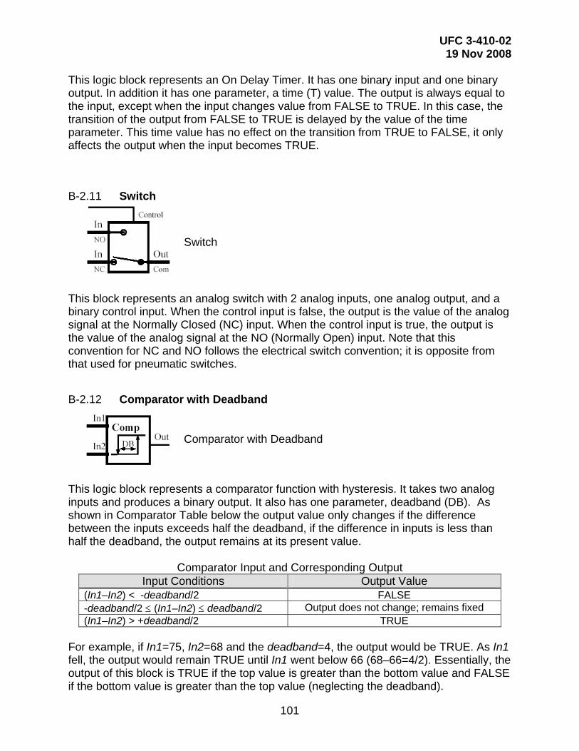
UFC 3-410-02 19 Nov 2008
101
This logic block represents an On Delay Timer. It has one binary input and one binary output. In addition it has one parameter, a time (T) value. The output is always equal to the input, except when the input changes value from FALSE to TRUE. In this case, the transition of the output from FALSE to TRUE is delayed by the value of the time parameter. This time value has no effect on the transition from TRUE to FALSE, it only affects the output when the input becomes TRUE.
B-2.11 Switch
Switch
This block represents an analog switch with 2 analog inputs, one analog output, and a binary control input. When the control input is false, the output is the value of the analog signal at the Normally Closed (NC) input. When the control input is true, the output is the value of the analog signal at the NO (Normally Open) input. Note that this convention for NC and NO follows the electrical switch convention; it is opposite from that used for pneumatic switches.
B-2.12 Comparator with Deadband
Comparator with Deadband
This logic block represents a comparator function with hysteresis. It takes two analog inputs and produces a binary output. It also has one parameter, deadband (DB). As shown in Comparator Table below the output value only changes if the difference between the inputs exceeds half the deadband, if the difference in inputs is less than half the deadband, the output remains at its present value.
Comparator Input and Corresponding Output Input Conditions Output Value
(In1–In2) < -deadband/2 FALSE -deadband/2 ≤ (In1–In2) ≤ deadband/2 Output does not change; remains fixed (In1–In2) > +deadband/2 TRUE
For example, if In1=75, In2=68 and the deadband=4, the output would be TRUE. As In1 fell, the output would remain TRUE until In1 went below 66 (68–66=4/2). Essentially, the output of this block is TRUE if the top value is greater than the bottom value and FALSE if the bottom value is greater than the top value (neglecting the deadband).

UFC 3-410-02 19 Nov 2008
102
B-2.13 Reset Schedule
Reset Schedule (output increases as input increases)
Reset Schedule (output decreases as input increases)
This block represents a reset schedule. It has one analog input, one analog output, and 4 parameters: InputMin, InputMax, OutputMin, and OutputMax. For the first reset schedule shown, the output increases as the input increases; as the input ranges from InputMin to InputMax, the output varies linearly from OutputMin to OutputMax. Inputs below InputMin or above InputMax result in the output going to OutputMin or OutputMax, respectively. For the second reset schedule shown, the output decreases as the input increases. The reset schedule block can be thought of as a graph, with the input variable on the X-axis and the output variable on the Y-axis.
B-2.14 Math Function
Math Function
This logic block represents a variety of mathematical functions. It takes two or more analog inputs and produces an analog output. Some common functions for this block are shown in the table below.
Common Math Block Functions Name Function
Minus Subtraction Minimum Select the minimum value from the input values Maximum Select the maximum value from the input values Plus Addition
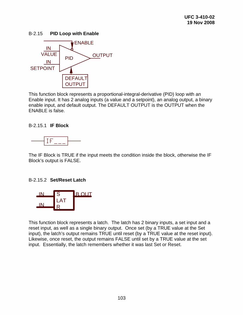
UFC 3-410-02 19 Nov 2008
103
B-2.15 PID Loop with Enable
DEFAULTOUTPUT
PIDVALUE
SETPOINTIN
INOUTPUT
ENABLE
This function block represents a proportional-integral-derivative (PID) loop with an Enable input. It has 2 analog inputs (a value and a setpoint), an analog output, a binary enable input, and default output. The DEFAULT OUTPUT is the OUTPUT when the ENABLE is false.
B-2.15.1 IF Block
The IF Block is TRUE if the input meets the condition inside the block, otherwise the IF Block’s output is FALSE.
B-2.15.2 Set/Reset Latch
SLATRIN
IN B OUT
This function block represents a latch. The latch has 2 binary inputs, a set input and a reset input, as well as a single binary output. Once set (by a TRUE value at the Set input), the latch’s output remains TRUE until reset (by a TRUE value at the reset input). Likewise, once reset, the output remains FALSE until set by a TRUE value at the set input. Essentially, the latch remembers whether it was last Set or Reset.