unified modeling language -...
TRANSCRIPT
Danang Wahyu Utomo
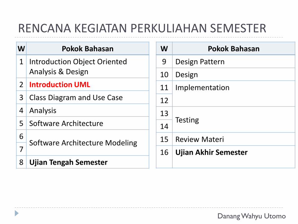
RENCANA KEGIATAN PERKULIAHAN SEMESTER
W Pokok Bahasan
1 Introduction Object Oriented Analysis & Design
2 Introduction UML
3 Class Diagram and Use Case
4 Analysis
5 Software Architecture
6Software Architecture Modeling
7
8 Ujian Tengah Semester
W Pokok Bahasan
9 Design Pattern
10 Design
11 Implementation
12
13Testing
14
15 Review Materi
16 Ujian Akhir Semester
Danang Wahyu Utomo
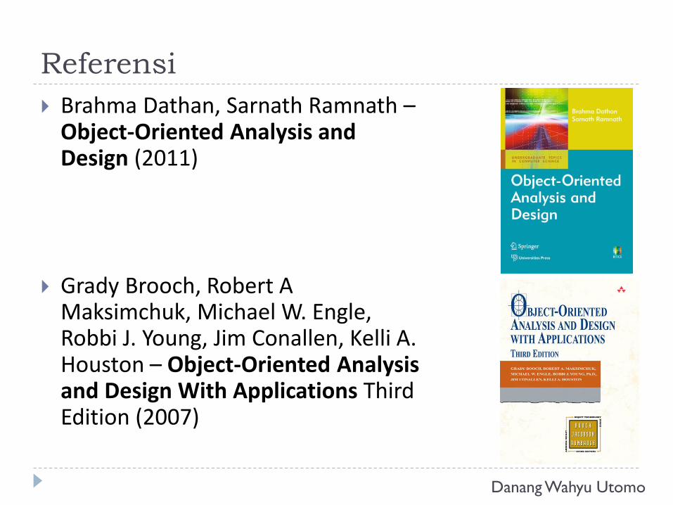
Referensi
Brahma Dathan, Sarnath Ramnath –Object-Oriented Analysis and Design (2011)
Grady Brooch, Robert A Maksimchuk, Michael W. Engle, Robbi J. Young, Jim Conallen, Kelli A. Houston – Object-Oriented Analysis and Design With Applications Third Edition (2007)
Danang Wahyu Utomo
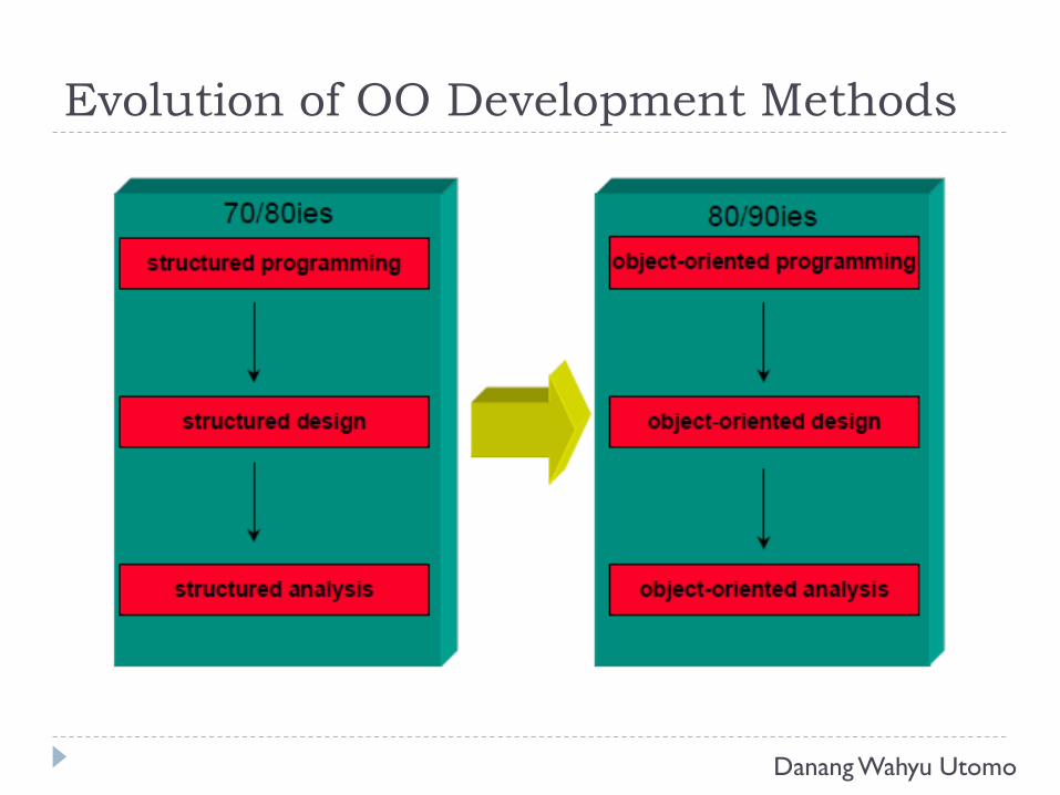
Evolution of OO Development Methods
Danang Wahyu Utomo
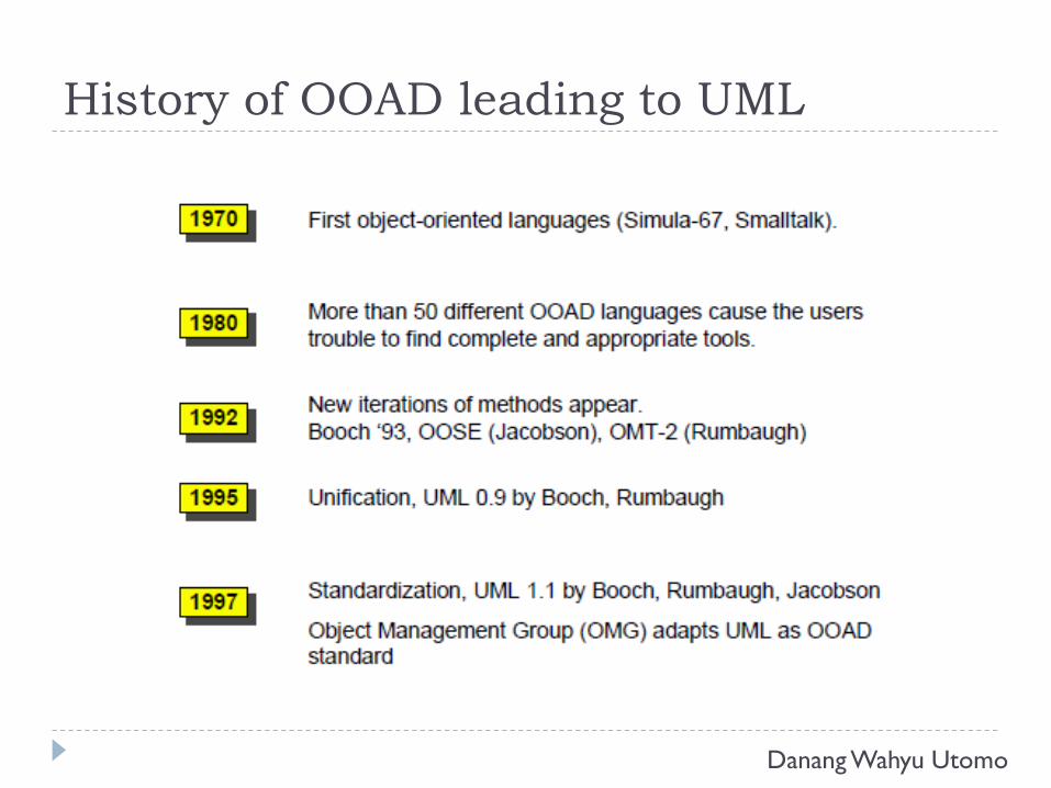
History of OOAD leading to UML
Danang Wahyu Utomo
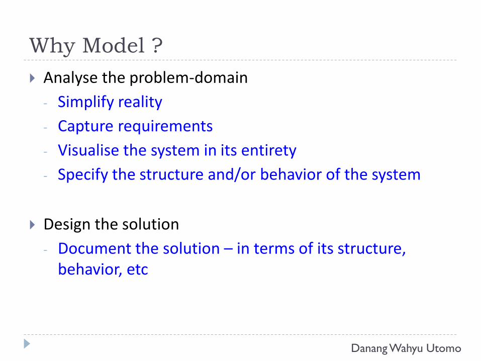
Why Model ?
Analyse the problem-domain
- Simplify reality
- Capture requirements
- Visualise the system in its entirety
- Specify the structure and/or behavior of the system
Design the solution
- Document the solution – in terms of its structure, behavior, etc
Danang Wahyu Utomo
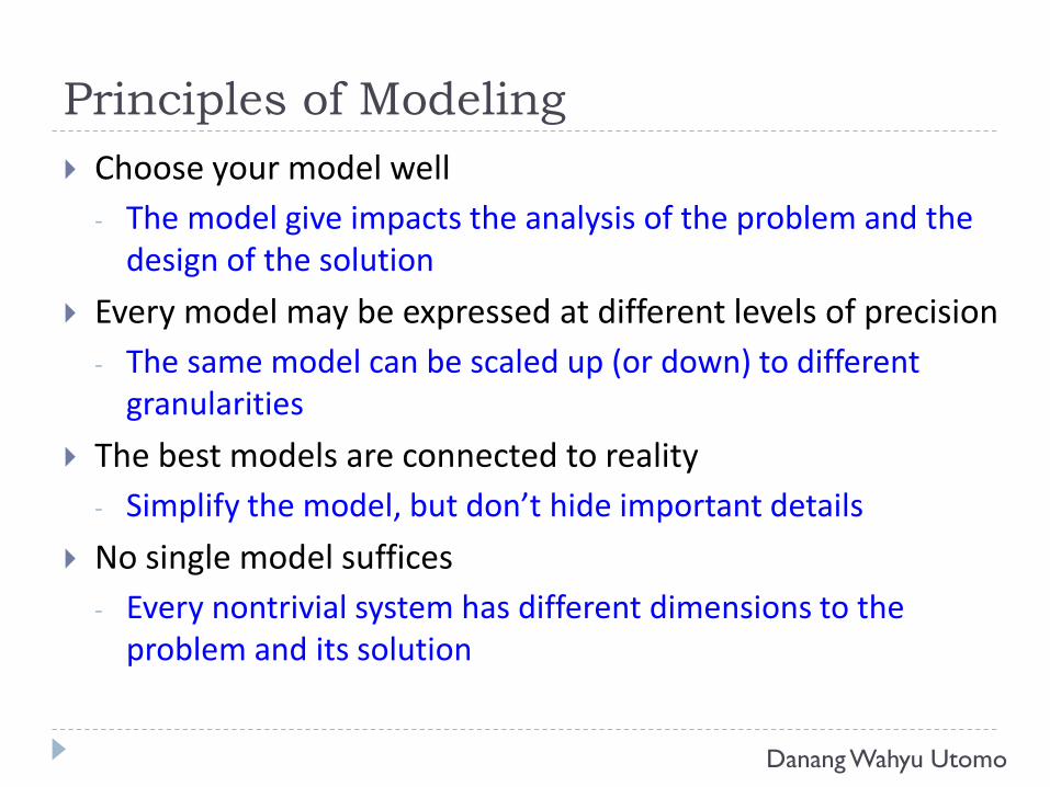
Principles of Modeling
Choose your model well
- The model give impacts the analysis of the problem and the design of the solution
Every model may be expressed at different levels of precision
- The same model can be scaled up (or down) to different granularities
The best models are connected to reality
- Simplify the model, but don’t hide important details
No single model suffices
- Every nontrivial system has different dimensions to the problem and its solution
Danang Wahyu Utomo
Unified Modeling Language
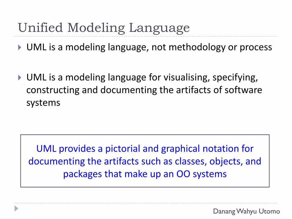
UML is a modeling language, not methodology or process
UML is a modeling language for visualising, specifying, constructing and documenting the artifacts of software systems
UML provides a pictorial and graphical notation for documenting the artifacts such as classes, objects, and
packages that make up an OO systems
Danang Wahyu Utomo
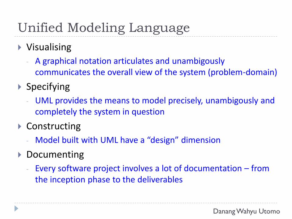
Unified Modeling Language
Visualising
- A graphical notation articulates and unambigouslycommunicates the overall view of the system (problem-domain)
Specifying
- UML provides the means to model precisely, unambigously and completely the system in question
Constructing
- Model built with UML have a “design” dimension
Documenting
- Every software project involves a lot of documentation – from the inception phase to the deliverables
Danang Wahyu Utomo
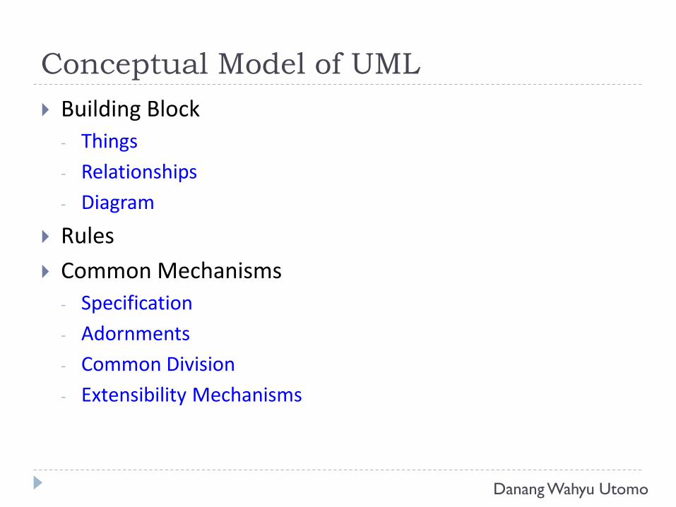
Conceptual Model of UML
Building Block
- Things
- Relationships
- Diagram
Rules
Common Mechanisms
- Specification
- Adornments
- Common Division
- Extensibility Mechanisms
Danang Wahyu Utomo
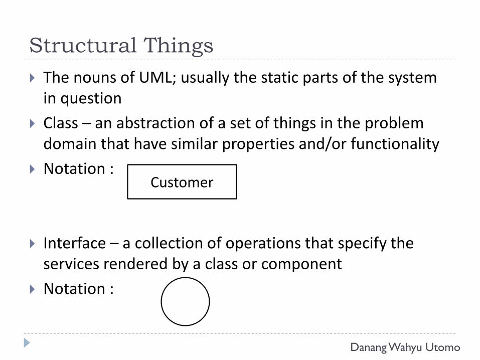
Structural Things
The nouns of UML; usually the static parts of the system in question
Class – an abstraction of a set of things in the problem domain that have similar properties and/or functionality
Notation :
Interface – a collection of operations that specify the services rendered by a class or component
Notation :
Customer
Danang Wahyu Utomo
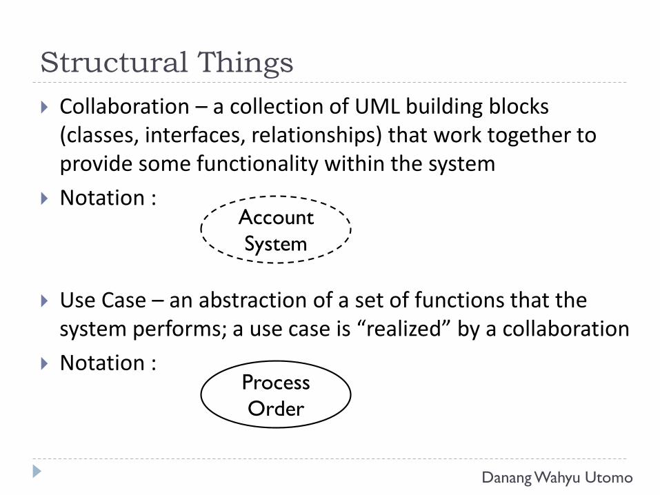
Structural Things
Collaboration – a collection of UML building blocks (classes, interfaces, relationships) that work together to provide some functionality within the system
Notation :
Use Case – an abstraction of a set of functions that the system performs; a use case is “realized” by a collaboration
Notation :
Account
System
Process
Order
Danang Wahyu Utomo
Structural Things
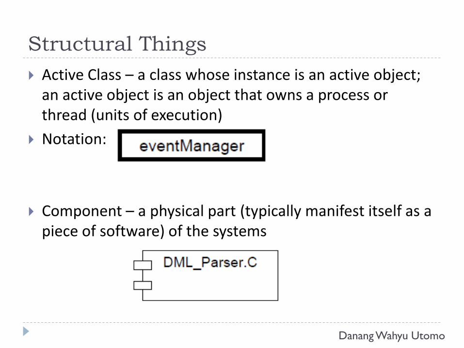
Active Class – a class whose instance is an active object; an active object is an object that owns a process or thread (units of execution)
Notation:
Component – a physical part (typically manifest itself as a piece of software) of the systems
Danang Wahyu Utomo
Structural Things
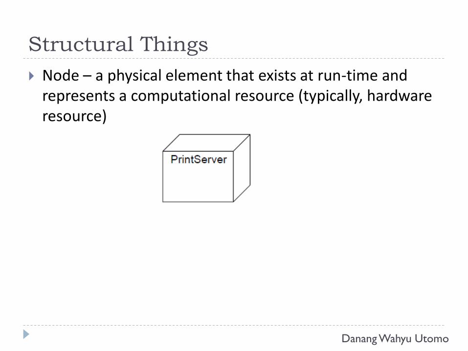
Node – a physical element that exists at run-time and represents a computational resource (typically, hardware resource)
Danang Wahyu Utomo
Behavioral Things
The verbs of UML models; usually the dynamic parts of the system in question
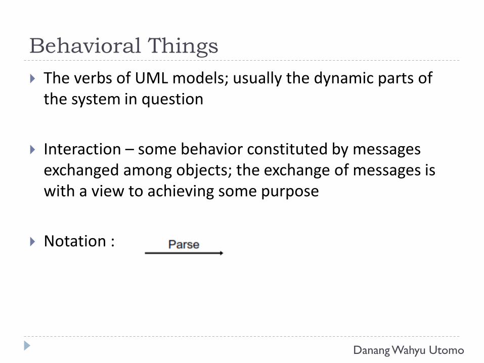
Interaction – some behavior constituted by messages exchanged among objects; the exchange of messages is with a view to achieving some purpose
Notation :
Danang Wahyu Utomo
Behavioral Things
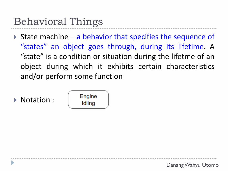
State machine – a behavior that specifies the sequence of“states” an object goes through, during its lifetime. A“state” is a condition or situation during the lifetme of anobject during which it exhibits certain characteristicsand/or perform some function
Notation :
Danang Wahyu Utomo
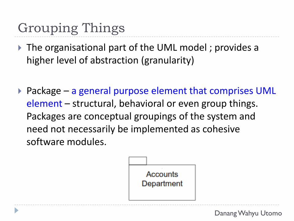
Grouping Things
The organisational part of the UML model ; provides a higher level of abstraction (granularity)
Package – a general purpose element that comprises UML element – structural, behavioral or even group things. Packages are conceptual groupings of the system and need not necessarily be implemented as cohesive software modules.
Danang Wahyu Utomo
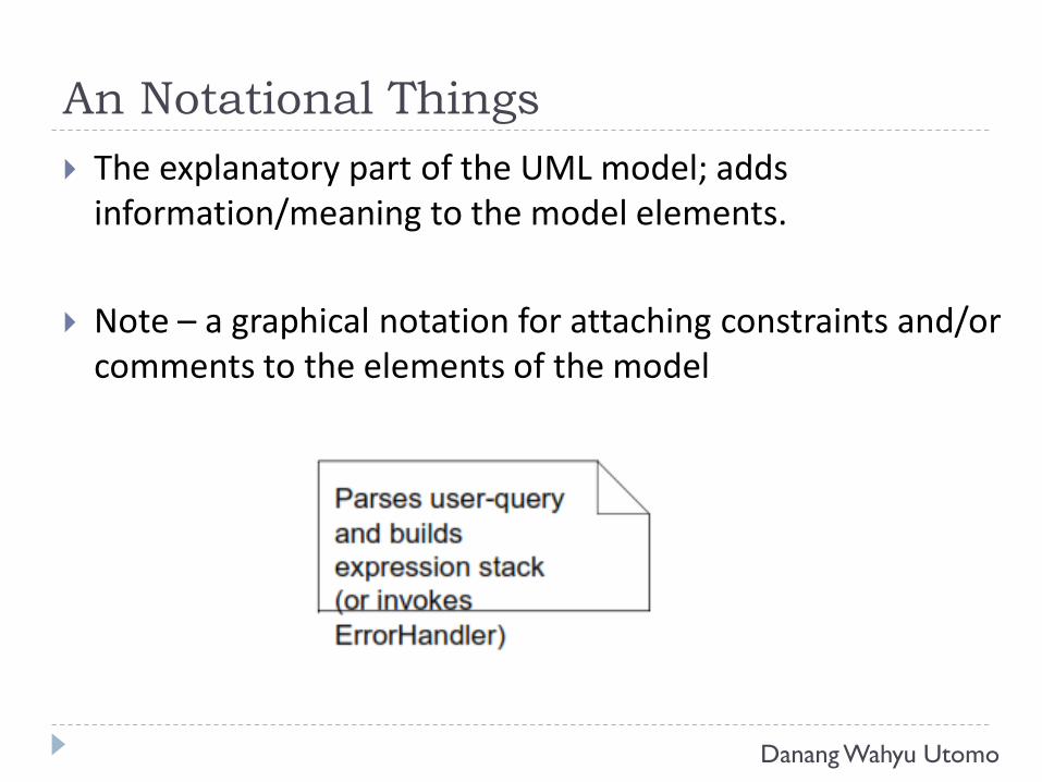
An Notational Things
The explanatory part of the UML model; adds information/meaning to the model elements.
Note – a graphical notation for attaching constraints and/or comments to the elements of the model
Danang Wahyu Utomo
Relationships
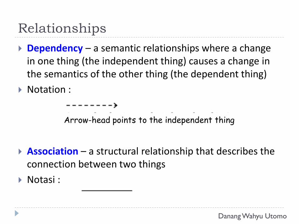
Dependency – a semantic relationships where a change in one thing (the independent thing) causes a change in the semantics of the other thing (the dependent thing)
Notation :
Association – a structural relationship that describes the connection between two things
Notasi :
Arrow-head points to the independent thing
Danang Wahyu Utomo
Relationships
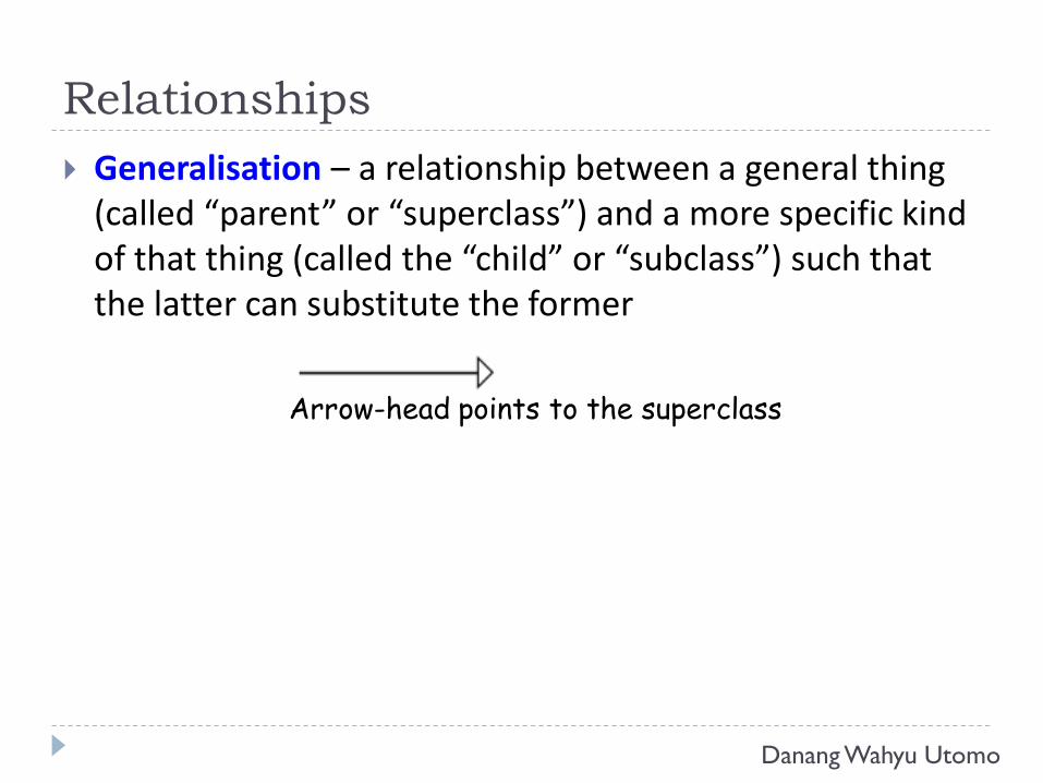
Generalisation – a relationship between a general thing (called “parent” or “superclass”) and a more specific kind of that thing (called the “child” or “subclass”) such that the latter can substitute the former
Arrow-head points to the superclass
Danang Wahyu Utomo
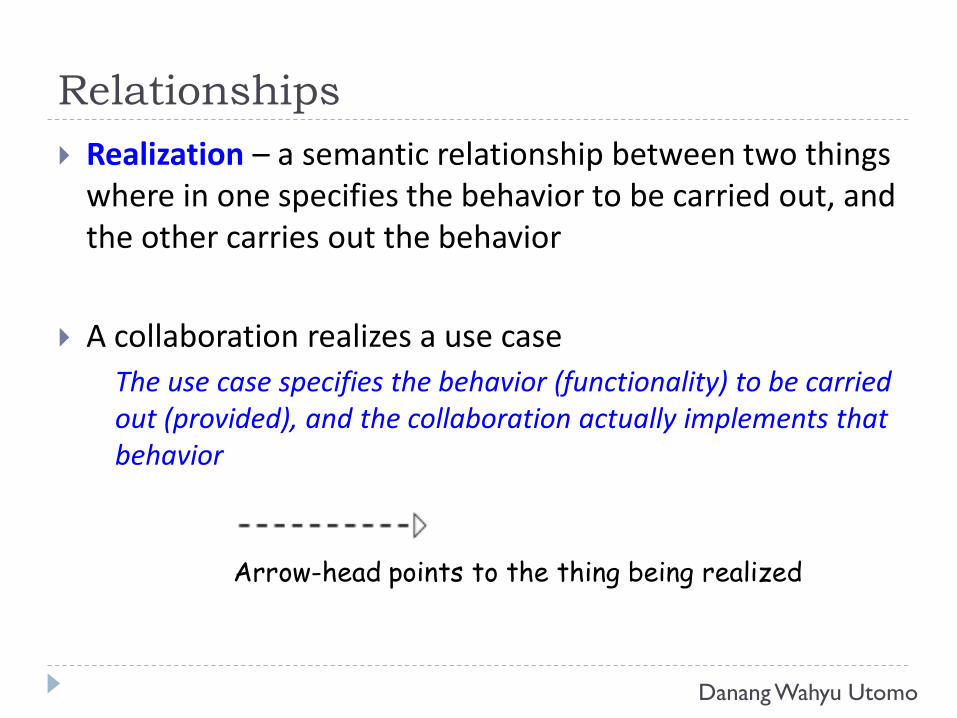
Relationships
Realization – a semantic relationship between two things where in one specifies the behavior to be carried out, and the other carries out the behavior
A collaboration realizes a use case
The use case specifies the behavior (functionality) to be carried out (provided), and the collaboration actually implements that behavior
Arrow-head points to the thing being realized
Danang Wahyu Utomo
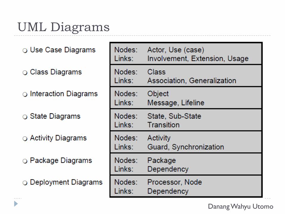
UML Diagrams
Danang Wahyu Utomo
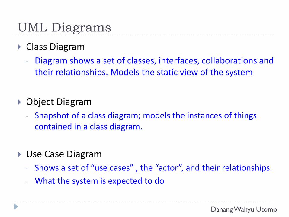
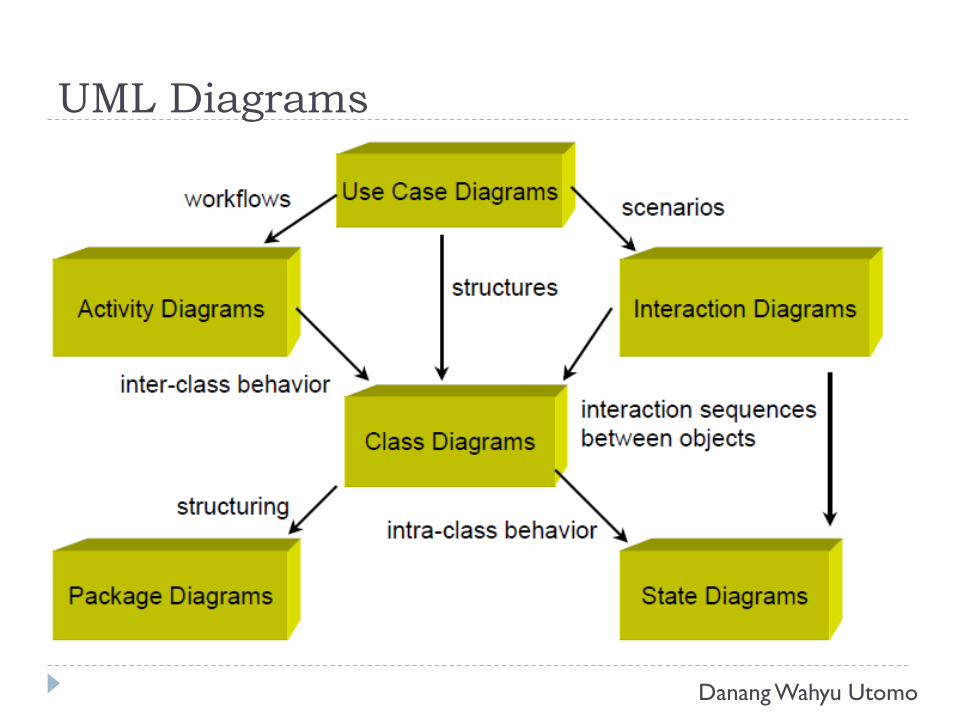
UML Diagrams
Class Diagram
- Diagram shows a set of classes, interfaces, collaborations and their relationships. Models the static view of the system
Object Diagram
- Snapshot of a class diagram; models the instances of things contained in a class diagram.
Use Case Diagram
- Shows a set of “use cases” , the “actor”, and their relationships.
- What the system is expected to do
Danang Wahyu Utomo
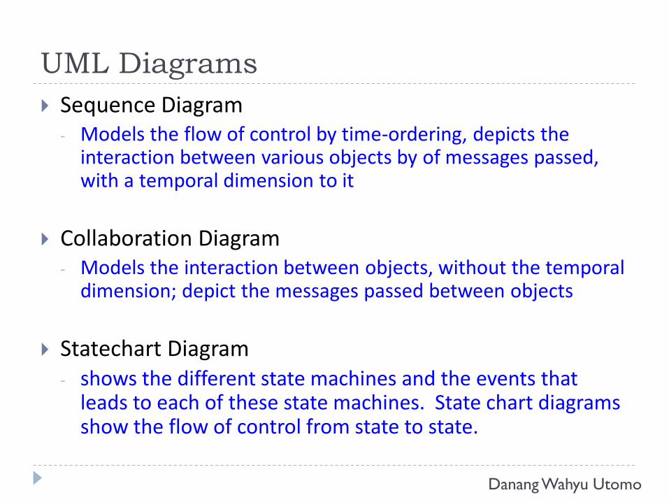
UML Diagrams
Sequence Diagram- Models the flow of control by time-ordering, depicts the
interaction between various objects by of messages passed, with a temporal dimension to it
Collaboration Diagram- Models the interaction between objects, without the temporal
dimension; depict the messages passed between objects
Statechart Diagram- shows the different state machines and the events that
leads to each of these state machines. State chart diagrams show the flow of control from state to state.
Danang Wahyu Utomo
UML Diagrams
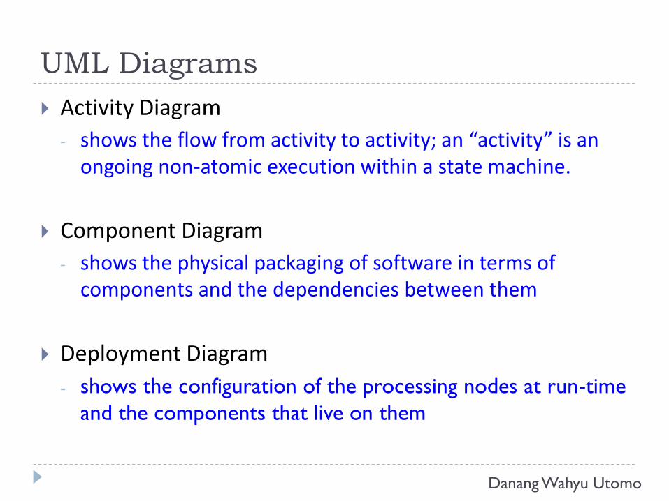
Activity Diagram
- shows the flow from activity to activity; an “activity” is an ongoing non-atomic execution within a state machine.
Component Diagram
- shows the physical packaging of software in terms of components and the dependencies between them
Deployment Diagram
- shows the configuration of the processing nodes at run-time
and the components that live on them
Danang Wahyu Utomo
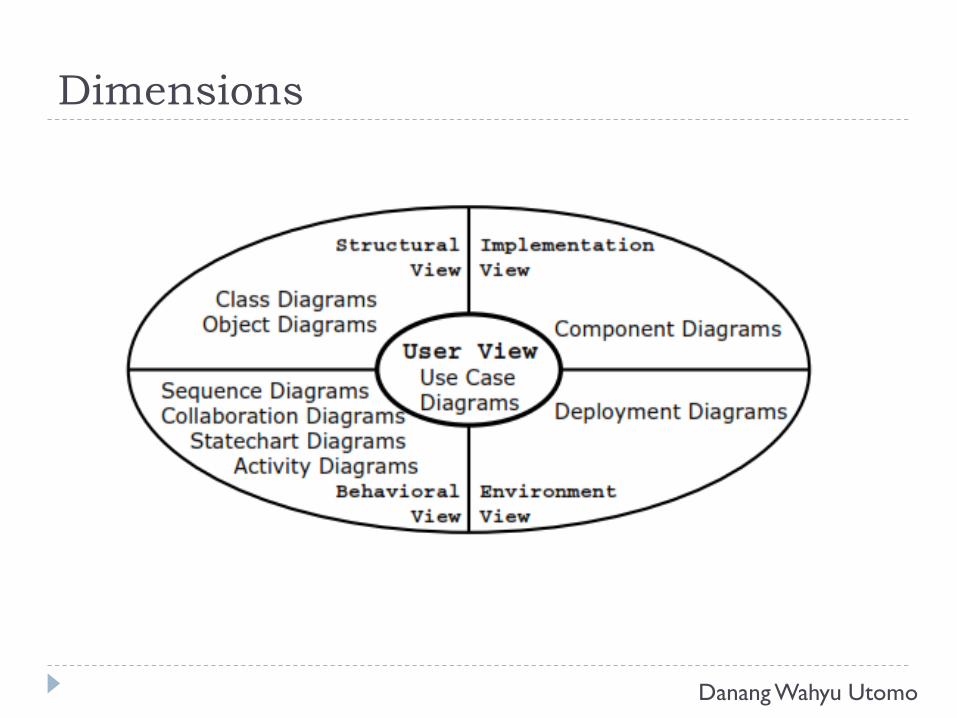
Dimensions
Danang Wahyu Utomo
UML Diagrams
Danang Wahyu Utomo
Diagrams and Process
Danang Wahyu Utomo
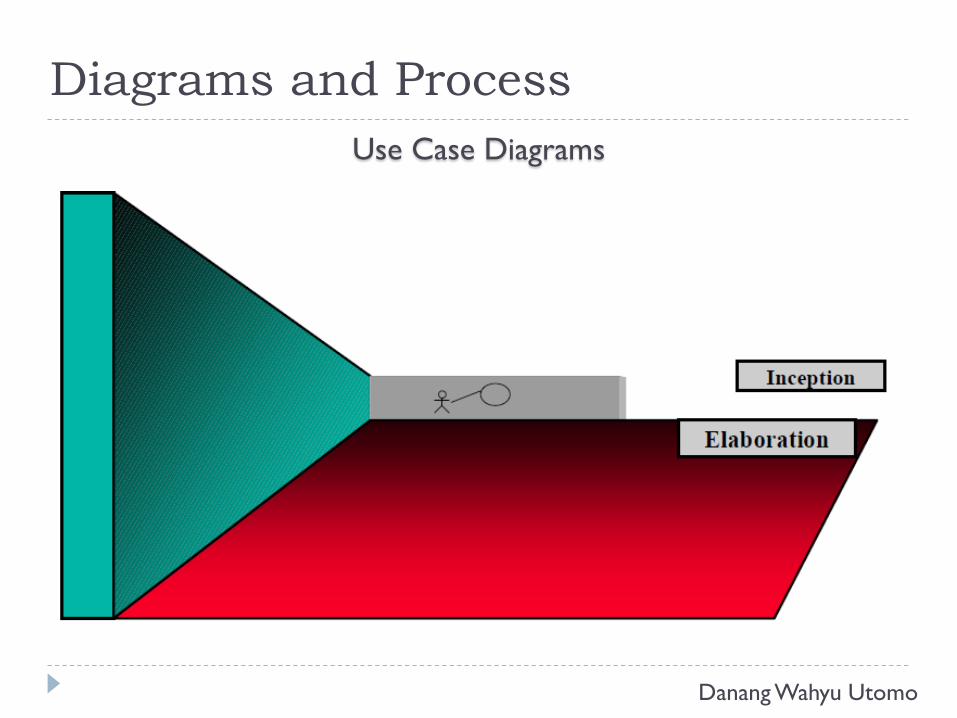
Diagrams and Process
Use Case Diagrams
Danang Wahyu Utomo
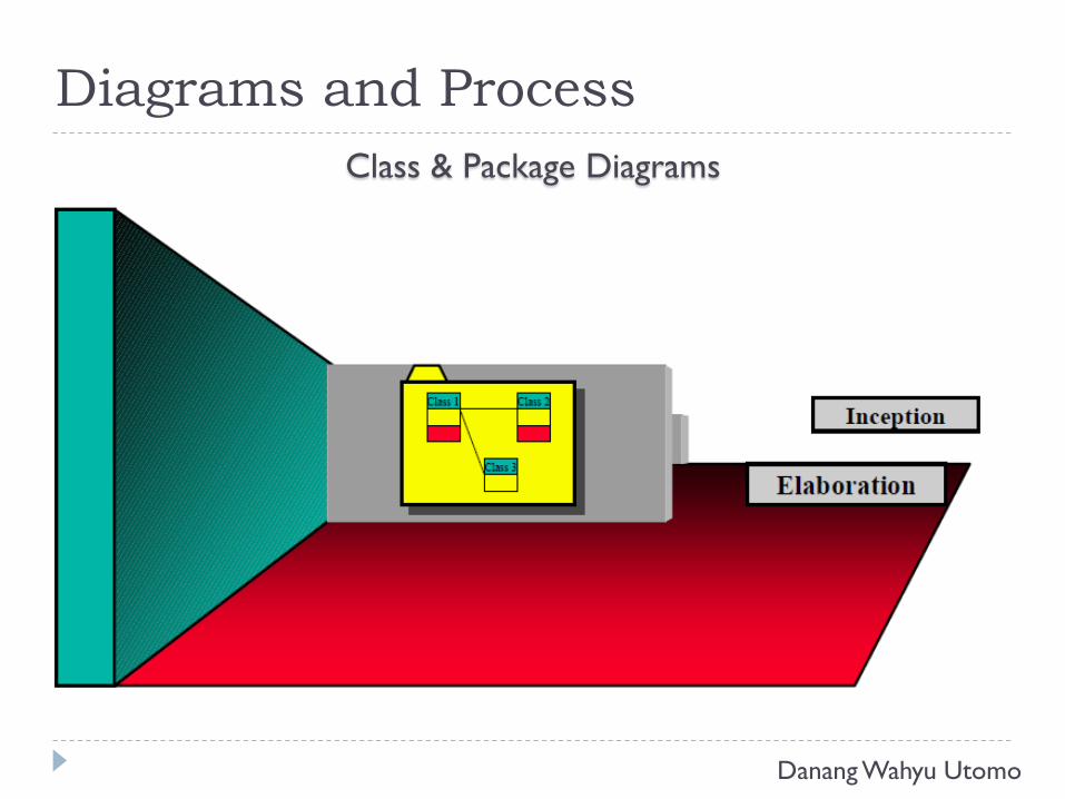
Diagrams and Process
Class & Package Diagrams
Danang Wahyu Utomo
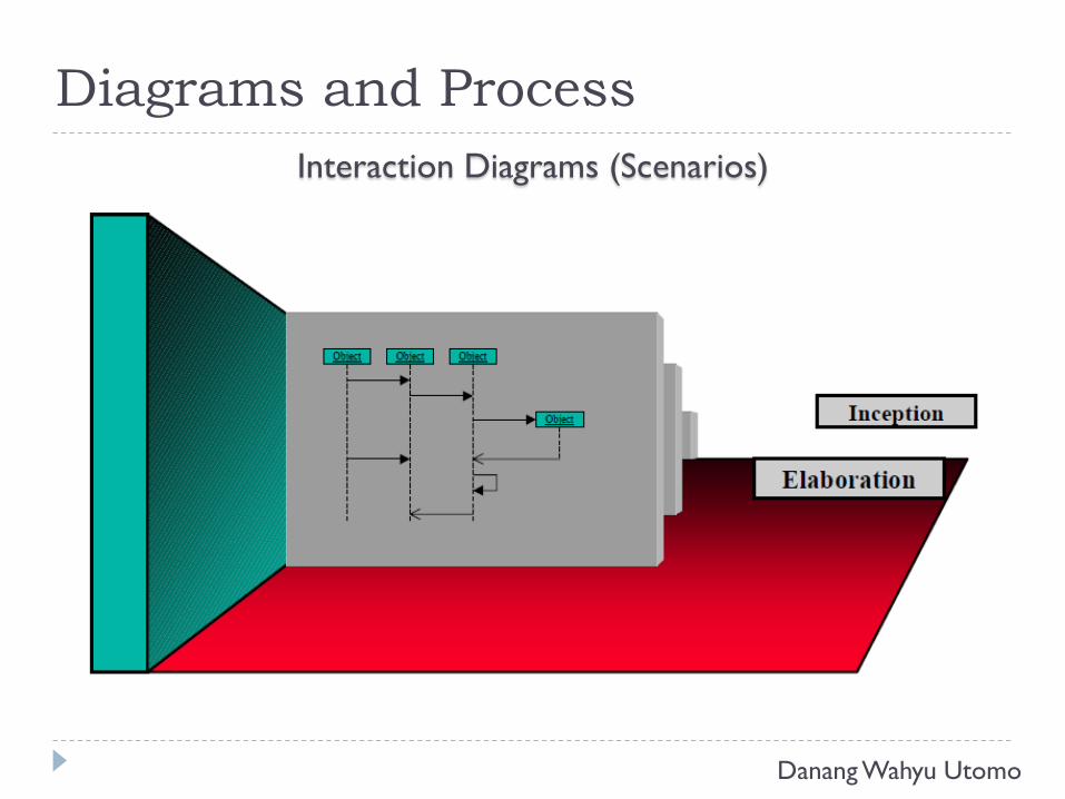
Diagrams and Process
Interaction Diagrams (Scenarios)
Danang Wahyu Utomo
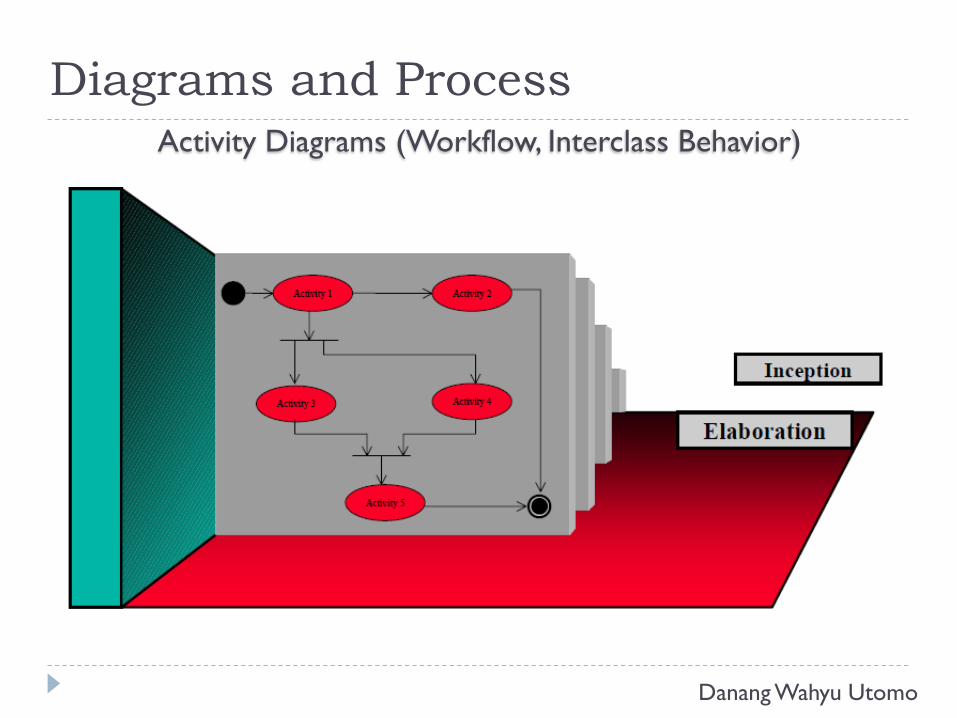
Diagrams and Process
Activity Diagrams (Workflow, Interclass Behavior)
Danang Wahyu Utomo
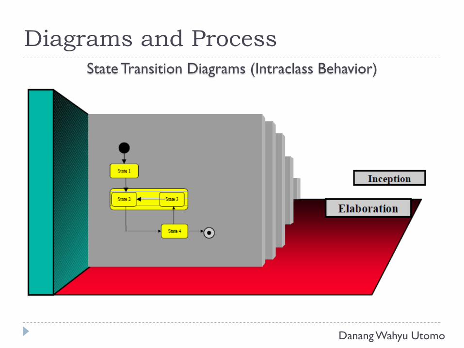
Diagrams and Process
State Transition Diagrams (Intraclass Behavior)
Danang Wahyu Utomo
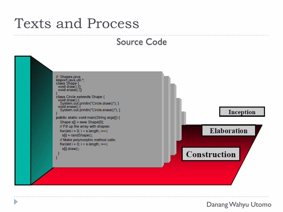
Texts and Process
Source Code
Danang Wahyu Utomo
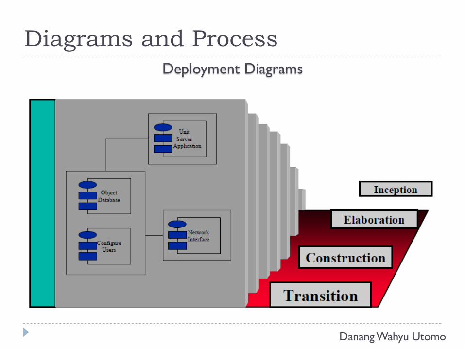
Diagrams and Process
Deployment Diagrams
Danang Wahyu Utomo
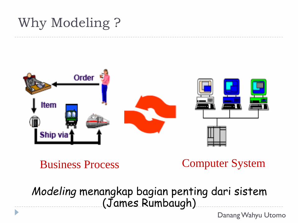
Business Process
Modeling menangkap bagian penting dari sistem(James Rumbaugh)
Computer System
Why Modeling ?
Danang Wahyu Utomo
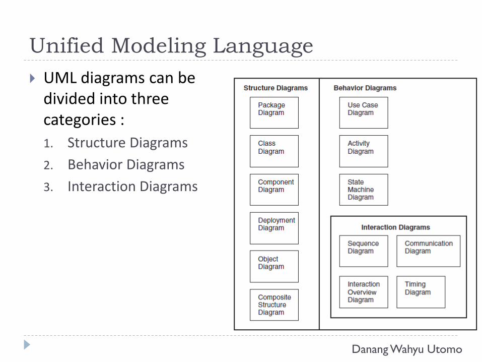
Unified Modeling Language
UML diagrams can be divided into three categories :
1. Structure Diagrams
2. Behavior Diagrams
3. Interaction Diagrams
Danang Wahyu Utomo
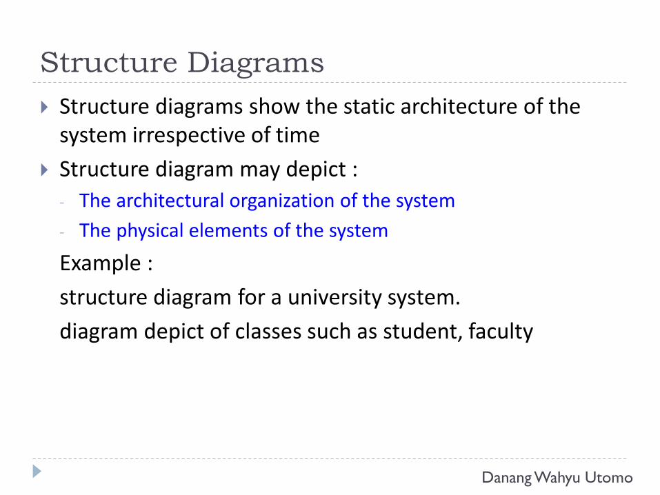
Structure Diagrams
Structure diagrams show the static architecture of the system irrespective of time
Structure diagram may depict :
- The architectural organization of the system
- The physical elements of the system
Example :
structure diagram for a university system.
diagram depict of classes such as student, faculty
Danang Wahyu Utomo
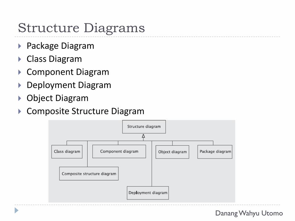
Structure Diagrams
Package Diagram
Class Diagram
Component Diagram
Deployment Diagram
Object Diagram
Composite Structure Diagram
Danang Wahyu Utomo
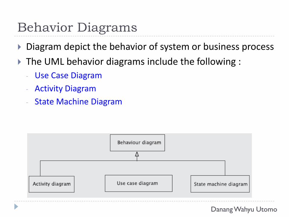
Behavior Diagrams
Diagram depict the behavior of system or business process
The UML behavior diagrams include the following :
- Use Case Diagram
- Activity Diagram
- State Machine Diagram
Danang Wahyu Utomo
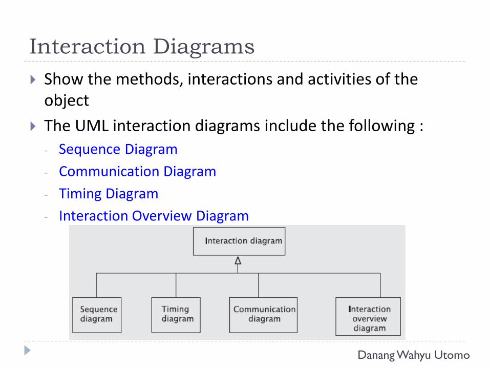
Interaction Diagrams
Show the methods, interactions and activities of the object
The UML interaction diagrams include the following :
- Sequence Diagram
- Communication Diagram
- Timing Diagram
- Interaction Overview Diagram
Danang Wahyu Utomo
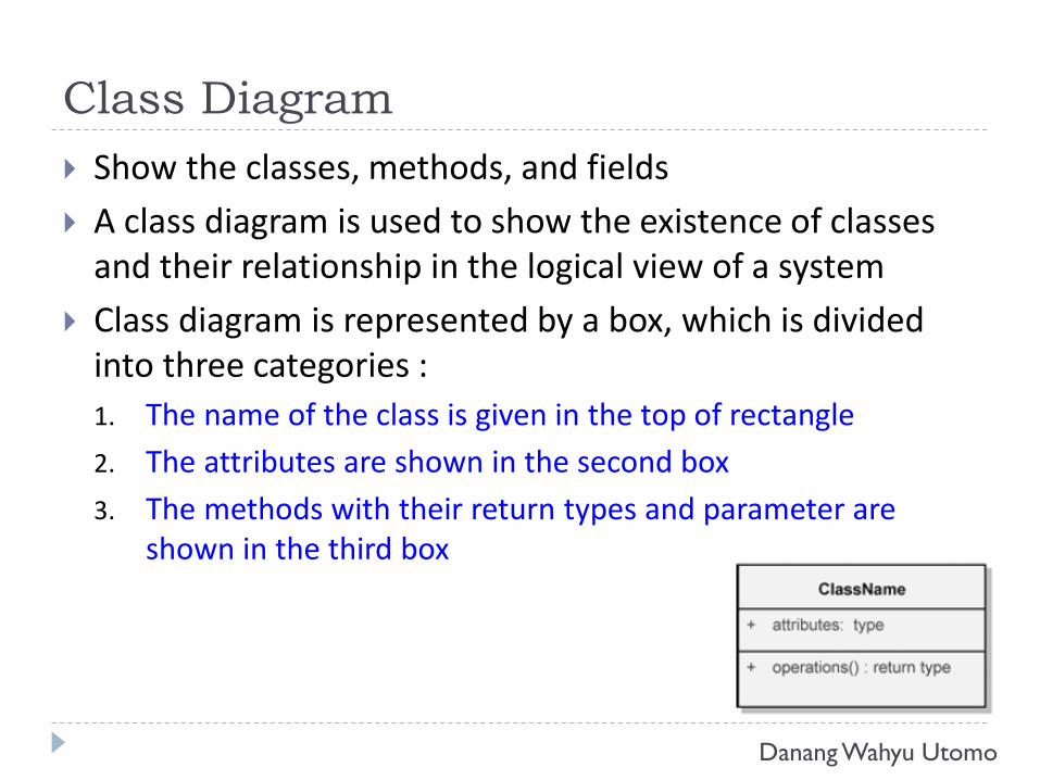
Class Diagram
Show the classes, methods, and fields
A class diagram is used to show the existence of classes and their relationship in the logical view of a system
Class diagram is represented by a box, which is divided into three categories :
1. The name of the class is given in the top of rectangle
2. The attributes are shown in the second box
3. The methods with their return types and parameter are shown in the third box
Danang Wahyu Utomo
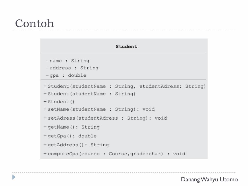
Contoh
Danang Wahyu Utomo
Class Relationships
Classes collaborate with other classes in a variety of ways
The essential connections among classes :
- Association
- Generalization
- Aggregation
- Composition
Danang Wahyu Utomo
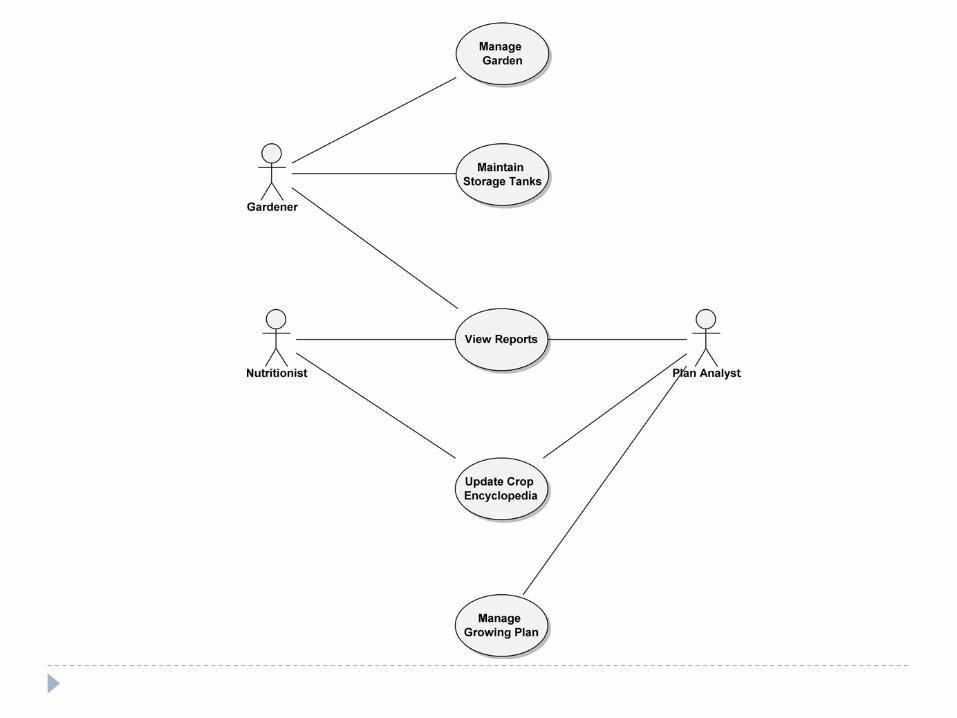
Use Case Diagram
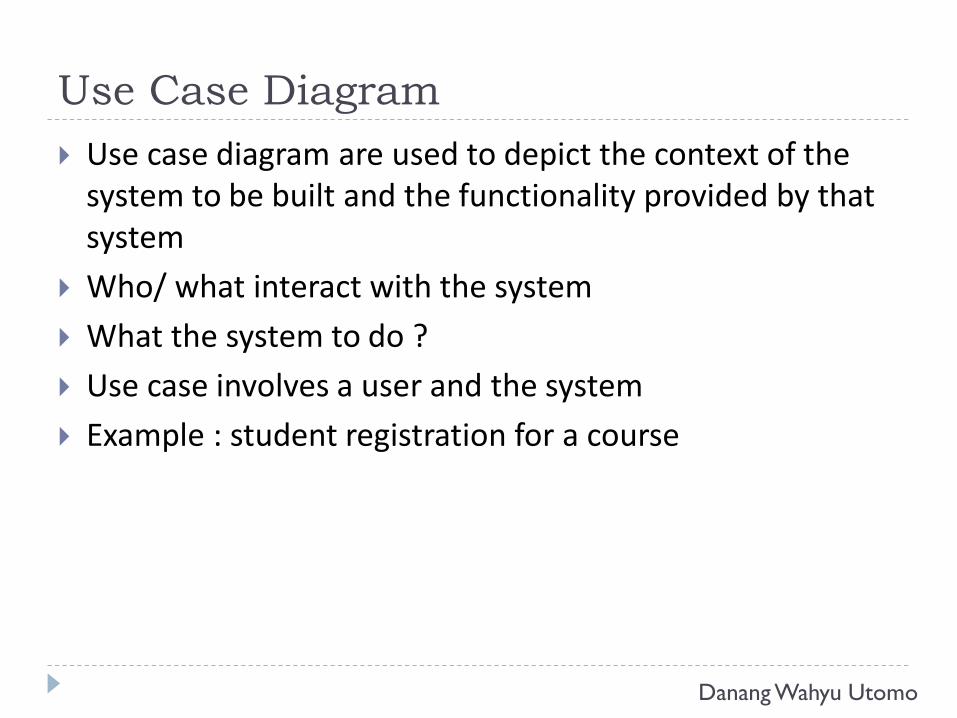
Use case diagram are used to depict the context of the system to be built and the functionality provided by that system
Who/ what interact with the system
What the system to do ?
Use case involves a user and the system
Example : student registration for a course
Danang Wahyu Utomo
Use Case Diagram
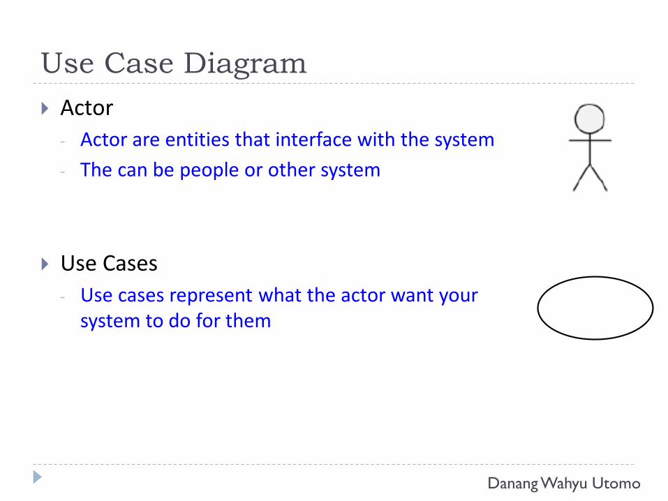
Actor
- Actor are entities that interface with the system
- The can be people or other system
Use Cases
- Use cases represent what the actor want your system to do for them
Danang Wahyu Utomo
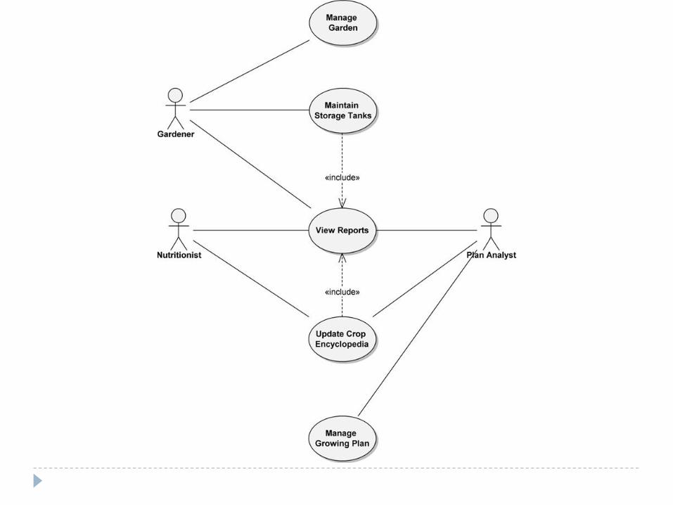
Include Relationship
<<include>> relationship represents behavior that is factored out of the use case
<<include>> behavior is factored out for reuse, notbecause it is an exception
<<include>> relationship is to the using use case
Danang Wahyu Utomo
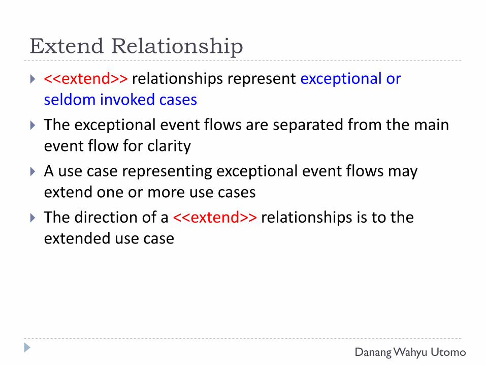
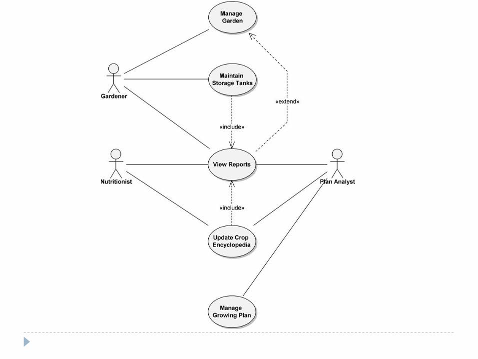
Extend Relationship
<<extend>> relationships represent exceptional or seldom invoked cases
The exceptional event flows are separated from the main event flow for clarity
A use case representing exceptional event flows may extend one or more use cases
The direction of a <<extend>> relationships is to the extended use case
Danang Wahyu Utomo
TERIMA KASIH