unit-05 vectors - drexel universitysteinberg/phys100/4 unit... · 1 unit-05 vectors introduction: a...
TRANSCRIPT

1
UNIT-05 VECTORS
Introduction: A physical quantity that can be specified by just a number – the magnitude – is known as a scalar. In everyday life you deal mostly with scalars such as time, temperature, length and mass of objects, etc. A vector is a physical quantity that requires both a magnitude and a direction for its specification. A simple example of a vector is the displacement – a change of position in a given direction - of an object. Another example of a vector quantity is the velocity of an object, which is defined as the rate of change of displacement with time. Since many engineering situations require us to represent quantities in terms of magnitudes and directions, engineering students must acquire the ability to represent the appropriate quantities as vectors and be able to manipulate these vector quantities. Learning Objectives of this UNIT.
1. Understand the characteristics of a vector quantity. 2. The polar description: Represent a vector quantity in terms of its magnitude
and direction, given a description of the physical situation. 3. Utilize the characteristics of two or more vectors that are concurrent, or
collinear, or coplanar. 4. Learn to add similar vector quantities. Be able to combine (add or subtract)
two or more vectors into a single, resultant vector using the graphical “tail-to-tip” and the parallelogram methods.
5. Resolve (break-up) a vector into components in specified directions. 6. The unit vector notation: Represent a vector in terms of its magnitude and a
unit vectors in the principal directions of a given reference frame. Combine vector components into a resultant vector, giving magnitude and direction in terms of orthogonal unit vectors in the reference frame.
Representation of a vector: A vector quantity is written as a letter with an arrow on top,
!A . In printed material it becomes cumbersome to type an arrow and therefore,
purely as a matter of convenience, vectors are represented by bold-type letters i.e. A where “A” is the magnitude of A. Graphically a vector is represented by a straight line drawn to a scale with the length representing the magnitude A and the arrow giving the direction of A. In Figure 1 below, the vector A represents a displacement of 10.0 m

2
along the x-axis where a scale of 1.0cm represents a displacement of 5.0m. The scaling factor in representing vectors is arbitrary and is dictated largely by convenience and spatial constraints.
FIGURE 1. Graphical representation of a vector. Addition of Vectors – Graphical Methods Only similar vectors (vectors representing the same physical quantity can be added – Velocity to velocity, force to force and so on) can be added. The Tail-to-Tip Method: To add two vectors A and B, place the tail of the second vector (B) at the head of the first vector (A). A third vector – let us say C drawn from the tail of the first (A) to the head of the second (B) gives the sum of the two vectors A and B. Graphically, the sum of two vectors is C = A + B.
FIGURE 2. Adding two vectors using the “tail-to-tip” method. Notes:
1. You can convince yourself that C = A + B = B + A 2. The sum of two vectors is also a vector.
The magnitude of C can be calculated as follows: From the Pythagorean theorem: C2 = h2 + (A+d)2 = h2 + A2 +d2 + 2Ad substitute, d = B cosβ and h2 + d2= B2 in the above equation to get C2 = A2 +B2 + 2ABcosβ = A2 +B2 + 2ABcos (180-α) = A2 +B2 – 2ABcosα C = (A2 + B2 – 2ABcos α)1/2 …[1]
X
Y
Ao2.0 cm
h
dA
BC =A+B
α β

3
We identify C as the sum of vectors A and B or alternately we can also identify A and B as component vectors of C. By a similar argument, we see that d is the component of B along the direction of A whereas h is the component of B along a direction perpendicular to A. When the two vectors A and B are at right angles, α = 900, we get C = (A2 + B2 – 2ABcos 900)1/2 = (A2 + B2)1/2 ...[2] (Note from eqs.[1] and [2] that the magnitude of the resultant vector C ! A + B . When A and B are collinear, C = A+B, and C = A – B when A and B are antiparallel) To add more than two vectors we simply extend the ‘tail over tip’ method. In Figure 3 below we have added three vectors A, B and D to get E = A + B + D = C + D.
FIGURE 3. Adding three vectors A, B, and D using the “tip-to-tail” method. The Parallelogram Method: This method is different in appearance but is fully equivalent to the tail-to-tip method. In this method you put the tails of the two vectors together, complete a parallelogram as shown below. The diagonal of the parallelogram is then the resultant of the two vectors. In the figure below we have added A and B to obtain C = A + B.
FIGURE 4. Adding two vectors A and B using the parallelogram method. Subtraction of Vectors and Multiplication by a Scalar:
A
BC =A+B
D
E = C+D
A
B C =A+B

4
The subtraction of a vector B from A can be viewed as adding A to a direction-reversed B. D = A – B = A + (- B) …[3] Graphically, eq.[3] is illustrated below for the tip-to-tail method:
FIGURE 5. Subtracting vectors B from vector A using the parallelogram method. Exercise 1: In the diagram below, which of the following vectors does X represent? [a] B – A [b] A – B [c] – [A + B]
Multiplication by a Scalar: Using the tail-to-tip method, it follows that A + A = 2A. Thus, multiplying a vector by a number simply increases the magnitude of the vector by a factor equal to the number but leaves the direction of the vector unchanged. Similarly, - 2A = 2(- A). Therefore, multiplying a vector by a negative number reverses the direction of the vector and increases the magnitude of the vector by a factor equal to the number modulus. In the example above, 2A is parallel to A. In general, if A = nB, where n is a number, then A and B are parallel to each other with A = nB. When n = 1, then A = B , and A = B. This means that two parallel
A
BC =A+B
D - B
A
B X
A
2A
A A
- 2A

5
vectors of the same magnitude are identical, i.e., they are the same vector. Rectangular Components of a Vector If A is along x-axis and B is along y-axis one can add them to get C = A + B. We call A and B as rectangular component vectors of C. See figure below. FIGURE 6. The rectangular components of a vector – in the diagram A and B are, respectively, the x- and y-components of vector C. From the definition of the sine and cosine functions, A/C = cosθ and B/C = sinθ Therefore, A = C cosθ and B =C sinθ …[4] A = C cosθ along x-axis is also called the x-component of C (= Cx). Similarly, B = C sinθ is called the y-component of C, and written as Cy. Magnitude of C can be obtained from its rectangular components as follows: Cx
2 + Cy2 = C2[cos2θ + sin2θ]= C2, since cos2θ + sin2=1
Therefore, C = (Cx
2 + Cy2)1/2
The direction of C is given by θ, the angle between C and the x-axis. We see that Cy / Cx = C sinθ / C cosθ = tanθ θ = tan-1[Cy / Cx ]
y
x
C
A
B
!

6
Thus, if we know the rectangular components Cx and Cy of a vector C, we can determine the magnitude C = (Cx
2 + Cy2)1/2 and direction from θ = tan-1(Cy / Cx) .
FIGURE 7. In the diagram C = A + B. Notice that Cx = Ax + Bx and Cy = Ay + By. The method of adding two vectors depicted in Fig. 7 can be extended to adding more than two vectors. When adding many similar vectors, say A, B, C… we can resolve each vector into its rectangular components (x- and y- components) and add all the x-components as scalars to find the resultant x-component (Rx = Ax + Bx + Cx +….) and add all the y-components to find the resultant y-component (Ry = Ay + By + Cy…). Once we know these resultant x- and y-components, we can get the magnitude of the resultant vector R = (Rx
2 + Ry2)1/2 and its direction from tanθ = (Ry / Rx).
Unit Vector Representation: So far we have been representing vectors graphically – we have been drawing them. Vectors can also be expressed algebraically or analytically – we can express them in the written form. A convenient way to do this is by using the concept of the unit vectors. A unit vector is defined as a vector of magnitude one (1). We define unit vectors that point along the three axes of a rectangular co-ordinate system.
FIGURE 8.The unit vectors.
A
B
C =A+B
Ay
x
y
Bx
B
A X
Y
Cx
Cy
X
Y
Z
ij
k
7
The unit vectors along the x-, y-, and z-axis are, respectively, called the i, j , and k. (Note: we will mostly work with two-dimensional vectors in the x-y plane and hence deal with only the i and j unit vectors. In the print form the three unit vectors are written as i , j, and k and are read as “ i-cap”, “j-cap”, and “k-cap”. In the typewritten format the unit vectors are written in lower case bold type.) Thus, C = Cx i + Cy j. In this representation, we can identify the components Cx and Cy
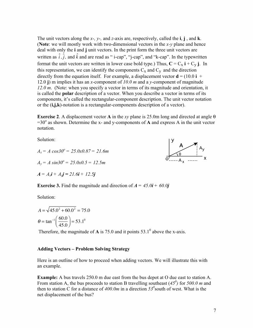
and the direction directly from the equation itself. For example, a displacement vector d = (10.0 i + 12.0 j) m implies it has an x-component of 10.0 m and a y-component of magnitude 12.0 m. (Note: when you specify a vector in terms of its magnitude and orientation, it is called the polar description of a vector. When you describe a vector in terms of its components, it’s called the rectangular-component description. The unit vector notation or the (i,j,k)-notation is a rectangular-components description of a vector). Exercise 2. A displacement vector A in the xy plane is 25.0m long and directed at angle θ =30o as shown. Determine the x- and y-components of A and express A in the unit vector notation. Solution:
Ax = A cos30o = 25.0x0.87 = 21.6m
Ay = A sin30o = 25.0x0.5 = 12.5m
A = Axi + Ayj = 21.6i + 12.5j
Exercise 3. Find the magnitude and direction of A = 45.0i + 60.0j
Solution: A = 45.02 + 60.02 = 75.0
! = tan"1 60.045.0
#$%
&'( = 53.1
0
Therefore, the magnitude of A is 75.0 and it points 53.10 above the x-axis. Adding Vectors – Problem Solving Strategy Here is an outline of how to proceed when adding vectors. We will illustrate this with an example. Example: A bus travels 250.0 m due east from the bus depot at O due east to station A. From station A, the bus proceeds to station B travelling southeast (450) for 500.0 m and then to station C for a distance of 400.0m in a direction 530south of west. What is the net displacement of the bus?
x
y
o
A
A
y
x
Aθ

8
Step 1. Choose x- and y-axes. Choose them in a way that will make your work easier. This is often done by choosing one of the axes along one of the given vectors. In our case we have aligned the first leg of the bus’s journey along the x-axis. Draw a well-labeled diagram(see the diagram on the left below).
Step 2. Find the components. Resolve each component into its x- and y-components (see the diagram on the right above). D1x = 250.0 m D1y = 0.0 m D2x = 500.0 cos450 m = 353.6 m D2y = - 500.0 sin450 m = - 353.6 m D3x = - 400.0 cos530 m = - 240.7 m D2y = - 400.0 sin530 m = - 319.5 m Step 3. Add the components. Dx = D1x + D2x + D3x = 250.0 + 353.6 – 240.7 = 362.9 m Dy = D1y + D2y + D3y = 0.0 – 353.6 – 319.5 = - 673.1 m Step 4. Find the magnitude and direction.
x
y
0 A
B
C
D 1
D3
D
D2
45o
53o
x
y
0 A
B
C
D 1
D3
D
D2
45o
53oD3x
D2x
D2y
D3y
θ

9
D = 362.92 + 673.12 = 764.7m
! = tan"1 Dy
Dx
#$%
&'(= tan"1 "673.1
362.7#$%
&'( = "61.70
Thus the total displacement of the bus is 764.7 m and it points 61.70 below the x-axis. Note : In the unit vector notation, the solution to this problem would be written as follows: D1 = 250.0 i m D2 = 500.0 cos450i - 500.0 sin450j = 353.6 i - 353.6j m D3 = - 400.0 cos530i - 400.0 sin530j = - 240.7 i - 319.5j m The net displacement: D = D1 + D2 + D3 = (250.0 + 353.6 – 240.7)i + (0.0 – 353.6 – 319.5)j = 362.9i - 673.1j m The magnitude and direction can now be determined as outlined above.

10
Solved Examples: Example 1. A vector A in the xy plane is 25.0m in magnitude and directed at angle θ =30o as shown. Another vector B is 30.0m in magnitude and perpendicular to A. [a] What are the x- and y-components of the resultant R = A+B? [b] Determine the magnitude and direction of the resultant vector R.
Solution:
[a] Ax = A cos30o = 25.0x0.866 = 21.6m
Ay = A sin30o = 25.0x0.5 = 12.5m
Bx = - B sin30o = - 30.0x0.5 = - 15.0m
By = B cos30o = 30.0x0.866 = 25.98m
Rx = Ax + Bx = (21.6 - 15.0)m = 6.6m
Ry = Ay + By = (12.5 + 25.98)m = 38.5m
[b] Magnitude, R = 6.62 + 38.52 = 39.1m
! = tan"1(38.5 / 6.6) = 80.3o Thus the resultant is 39.1m and points 80.30 above the x-axis. Example 2. A fishing boat sets out to sail to a point 12.0km due north. Without catching many fish, the boat sails further to a point 9.0km due west for better fishing. From the second spot, how far and in which direction must the boat sail to reach its original starting point?
Solution: To get back to O, the boat must travel along C. From the diagram: A + B + C = 0 or C = - ( A + B ) = - ( 12.0 i - 9.0 j) km Magnitude of C = [(12.0)2 + (9.0)2]1/2 = 15.0 km. θ = - tan-1[9.0/12.0] = - 37o
x
y
o
Aθ
Bθ
A
B
C
ox(East)
y(North)
θ
12.0
km
9.0 km

11
B A
C
500 miles
600 miles
D
N
S
E W
53o
Thus the boat must sail 15.0 km, 37o south of east. Example 3. Loosening a nut on a bolt is a common experience and we see how a force applied may be split into various components. In order to loosen a nut, a person holding a horizontal wrench exerts a downward force F = 50.0 lb at an angle of 30° to the vertical. [a] What are the horizontal and vertical components of the force F?
The vertical component, FV = – 50.0 cos 30° = – 43.3 lb The horizontal component, FH = – 50.0 sin 30° = – 25.0 lb Negative signs indicate the components are along the negative x- and y-axes. [b] Express F in the unit vector i and j notation. F = FH i + FV j = [– 43.3 i – 25.0 j ] lb Example 4: In the first leg of its flight an airplane flies from city A to city B in a direction due east for 600.0 mi (mi = miles). Next, it flies from city B to city C, in a direction 53°north of east for 500.0 mi.
[a] Determine the components, along the easterly and northerly directions, of the
resultant displacement of the plane from city A to city C. Let dx and dy represent, respectively, the components of the plane’s
displacement along the east and the north.

12
dx = 600.0 + 500.0•(cos53°) mi = 900.0 mi. dy = 500.0•(sin 53°) mi = 400.0 mi [b] What are the magnitude and direction of the resultant displacement of the
plane from city A to city C? Magnitude: d = (900.02 + 400.02)1/2 = 984.9 miles Direction: tan θ = 400.0/900.0 = 4/9, so θ = tan-1 (4/9) = 24.0°.
This direction is 24.0° North of East.
The plane then flies directly from city C to city D — directly north of city A, a distance of 400.0 miles in the last segment of its flight.
[c] What is the magnitude and the direction of the displacement of the plane from
city C to city D?
Magnitude = 900.0 miles. This direction is westerly; see the vector representation below.
[d] What is the net displacement of the plane as it flies from city A to city D? The net displacement, R = 400.0 i mi or 400.0 mi pointing north. [e] What is the total distance the plane has traveled as it flew from A to D. The total distance = 600.0 + 500.0 + 900.0 = 2000.0 mi
B A
C
24 o
COMPONENT DUE EAST
29 oo
D
d f = 400 miles
53 o
d 3 = 900 miles
d = 985 miles d 2 = 500 miles
d 1 = 600 miles
13
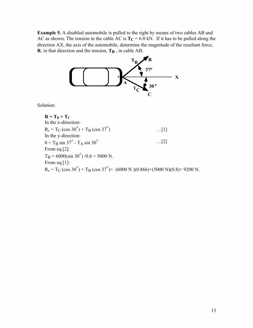
Example 5. A disabled automobile is pulled to the right by means of two cables AB and AC as shown. The tension in the cable AC is TC = 6.0 kN. If it has to be pulled along the direction AX, the axis of the automobile, determine the magnitude of the resultant force, R, in that direction and the tension, TB , in cable AB.
Solution:
R = TB + TC In the x-direction: Rx = TC (cos 30°) + TB (cos 37°) …[1] In the y-direction: 0 = TB sin 37° - TA sin 30° …[2] From eq.[2]: TB = 6000(sin 30°) /0.6 = 5000 N. From eq.[1]: Rx = TC (cos 30°) + TB (cos 37°)= (6000 N )(0.866)+(5000 N)(0.8)= 9200 N.