unit-7
DESCRIPTION
for electrical engineersTRANSCRIPT

UNIT 7 ENERGY CONVERSION PRINCIPLES AND D.C. MACHINES
Structure 7.1 lntroduction
Objectives
7.2 Principles of Electromechanical Energy Conversion 7.2.1 Induced Electromotive Force and Voltage 7.2.2 Force on a Current Carrying Conductor 7.2.3 Back EMF and Counter Torque
7.3 Losses, Heating and Efficiency 7.3.1 ElectromagneticLosses 7.3.2 Mechanical Losses 7.3.3 Efficiency, Heating and Rating
7.4 Direct Current Generators 7.4.1 Constructional Features 7.4.2 Armature Windings, EMF and Counter Torque 7.4.7 Excitation Schemes and Magnetisation Characteristic
7.4.4 Load Characteristics
7.5 Direct Current Motors 7.5.1 Excitation Schemes for DC Motors 7.5.2 Motoring Action and Speed Equation 7.5.3 Shunt Motors
7.5.4 Series Motors 7.5.5 Compound Motors
7.6 Summary
7.7 Answers to SAQs
7.1 INTRODUCTION
Rotating electrical machines are energy conversion devices which link an electrical system to a rotating mechanical system. When energy flows from the mechanical system to the electrical system, the device is said to function as a generator. When energy flows from the electrical system to the mechanical system, the device is said to function as a motor. This process of energy transfer is reversible, and a11 electrical machine can be made to work either as a generator or as a motor. During such energy transfer, part of the energy is lost as heat energy, leading to an energy conversion efficiency which is always less than 100%.
The electrical power system to which the machine is c o ~ e c t e d may be an ac system at 50 Hz (60 Hz in the USA) or a dc system. The three phase synchronous machine and the induction machine constitute the principal types of ac machines. DC machines are classified in terms of the schemes used for providing the magnetic field or excitation of the machines.
In this unit we will confine ourselves to a study of dc machines. AC machines will be considered in Unit 8.
Objectives After studying this unit, you should be aPle to
use the Blv and Bli formulas for calculating emf and torque,
identify and list the various components of energy loss,
describe the constructional features of the heteropolar field syslem used in dc machines,
give an elementary description of dc armature windings and the commutator,
explain the various excilation schemes used in dc machines,
calculate induced emf and terminal voltage of dc generators, and
calculate torque and speed of dc motors.

E k t r i c a l Machiis Me~suriog lmtrumene 7.2 PRINCIPLES OF ELECTROMECHANICAL ENERGY
CONVERSION
In an electromechanical energy conversion device, energy transfer between the electrical and mechanical systems takes place through the agency of the magnetic and electric fields. In the rotating electrical machines considered in this unit, the energy stored in the electric field is negligible and conversion takes place mainly via the magnetic field. The principal phenomena to be considered in such machines are (i) the generation of electromotive force or voltage in the windings and (ii) the production of forces on current carrying conductors resulting in torque.
7.2.1 Induced Electromotive Force and Voltage Faraday's law of induction, as in the transformers discussed in Unit 6, plays an important role in understanding the phenomena governing the operation of rotating electrical machines. This law states that an electromotive force (emf) is induced in any coil whose magnetic flux linkages are changing with time. The voltage produced satisfies the equation
where
N = number of turns of the coil;
cp = flux linking the coil in webers;
h = Ncp is the total flux linkages of the coil and
gq = rate of change of the flux. dt
Eq. (7.1) gives the voltage drop in the direction of assumed positive current flow provided the convention is adopted that positive current in the coil sets up a positive flux cp and a positive flux linkage h Equivalently, the orientation of the current in the loop must be so selected that a right handed screw, if turned in that direction, will advance in the direction of positive flux. In Eq. (7.1) it is assumed that the same flux cp links each one of the N turns.
In the transformer, the rate of change of flux linkage was entirely due to changing currents in the various coils, the coils themselves remaining stationary. In rotating machines, rotary motion is a very important factor in producing change of flux linkage. In fact using vector calculus, it can be shown that the induced emf can be split into two components viz., (i) a transformer emf and (ii) a motional emf. When applied to a coil moving in a magnetic field which is itself changing with time, the transformer emf is the emf that would be produced if the coil remained stationary at its position at time t, while the flux continued to follow its own law of variation with time. The motional emf, on the other hand, depends on the velocity of each part of the coil at time t, the flux density at each part being considered constant at its value at time t.
If a conductor of length 1 is situated in a magnetic field with a uniform flux density of B teslas and the velocity of the conductor is v, the motional emf is given by
e = Blv volts, (7.2)
provided the directions of B, 1 and v are at right angles to each other. The conductor of length 1 meters is said to cut the magnetic flux density B with a velocity of v metres per second. Eq. (7.2) is therefore often called theflux cutting rule. The direction in which e acts may be determined by the so called Fleming's right-hand rule for emf. In this rule, if the thumb, fore-finger and middle finger of the right hand are held mutually at right angles such that the fore-finger points in the direction of magnetic field B and the thumb in the direction of motion (velocity), then the middle finger points in the direction of induced voltage rise.
Example 7.1
(a) A coil of 100 turns has a flux of 0.01 Wb linking it. If the flux is reversed in direction at uniform rate in 1 ms (the coil being stationary), find the value of the induced voltage.

(b) A conductor of length 20 cm is moved at a linear velocity of 10 m/s at right Conversionprinciples
angles to a magnetic field. The induced emf is 0.5 V. Find the flux density of *d D.C Machilles
the field.
Solution OL
(a) Nett flux change = 0.01 - (4 .01) = 0.02 Wb This change occurs uniformly in 1 rns = 10-~s
& - 0.02 = 20&,s and Therfore - dt 0.001
e (b) B = - (from Eq. (7.2))
lv
- - 0.5 = 0.25 tesla.
0.2 x 10
We will now use Faraday's law of induction to demonstrate the validity of the-flux cutting rule by evaluating the induced voltage in a rectangular coil. (Many practical windings used in electrical machines may be regarded as equivalent to rectangular coils. Consequently the results of this analysis will be of direct use later). Figure 7.1 shows a rectangular coil ABCD with its sides parallel to the X- and Y-axes of a right-handed rectangular coordinate system. The flux density B is assumed to be a function only of x, (independent of time t and the other space coordinates y and z), and to be directed in the positive z-direction. At time t, let the rectangular coil be in the position shown and let the flux density at x = x, be B,
Figure 7.1 : Motional Voltage In Moving Coil
and at x = x,, B,. In the differential time dt, the entire coil will move towards the right through a distance (vdt) when v is the velocity of the movement. Due to'this motion, the flux linking the coil will increase by an amount B, lvdt due to the motion of conductor CD, and reduce by an amount B,lv dt due to the motion of conductor AB. The nett increase of flux linkage dq is therefore given by
The induced voltage by Faraday's law is therefore
Using the convention appropriate to Faraday's law, this is the induced voltage drop acting in the direction of the loop ABCD. (In applying Faraday's law, as stated earlier,the orientation of the loop must be so selected that a right handed screw, if turned in that direction, will advance - in the direction of ,the positive flux linkage).
By the flux cutting rule, no voltages will be produced in the conductors BC and DA as the motion has no component perpendicular to these conductors. In conductor AB, using Fleming's right hand rule,-there is a voltage rise from A to B equal to B, lv and in conductor CD, a voltage fall from C to D given by B, lv. Therefore, round the loop ABCD, the total ,
voltage fall is (B,- B, ) lv, in agreement with Eq. (7.3a).

Electrical ~ ~ h i n e s & If B is a function of time, Eq. (7.2) will no longer give the total induced emf. However, it Mem-g can be used to compute the component of emf we have described as the motional emf
provided the'yalues used for B, and B, are their values B,(t) and B2(t) at time t when the coil is passing through the position shown. To get the correct values of induced emf we have to add the transformer emf which is given by
Here x , and x, must be treated as constants (with time derivatives taken to be zero) having the values x,(t) and x2(t). These statements are clarified in the illustrative examples which follow.
Example 7.2
PQ in Figure 7.2 is a representation of the rectangular coil of Figure 7.1, as seen in cross-section across XX, when located in a z-directed magnetic field of rectangular waveform and peak value Bo tesla. The coil of width 0.2 m and length 1 = 0.1 m, is in motion at a constant velocity v = 20 m/s from left to right. The rectangular magnetic field is periodic and has a half wave-length of 0.2 m. At time t = 0, the coil PQ is in the position shown such that the flux through it has the maximum value of (0.2 x 0.1 x Bo ) Wb
(a) Find the emf induced in the coil round the loop ABCD using (i) the flux cutting rule; (ii) Faraday's law of induction.
(b) What are the values of the motional emf and transformer emf in this case ? Explain.
Figure 7.2 : Diagram for Example 7.2
Bz' v = 2 0 m / s
Solution
Pf ,
Assuming that P is at x = 0 when t = 0, at any time t conductor AB (see Figure 7.1) is at position xl = vt = 20 r and conductor CD is at x2 = (20t + 0.2)
length 1 = 0.1 m
? Bo 4 2 m -
,,Q
(a) (i) During the time 0 < t < 0.01s, the voltage rise fromA to B by the flux cutting and right hand rules is B, x 0.1 x 20 = 2 Bo V. The emf rise from C to D is also B, x 0.1 x 20 = 2 Bo V. Therefore, the emf rise round the loop ABCD is a constant of value (2B0 + 2B0) = 4B0 V.
V \ J C X
--2m -- d o
During the period .Ols < r < .02s,,the induced emfs have the same magnitudes as before, but rise in the opposite direction. The emf rise round the loop ABCD is now a constant equal to (4B0) V. The induced emf thus has a rectangular waveform in time of peak value 4B0 V, the period being T = (0.01 + 0.01) = 0.02s. This corresponds to a frequency f = (1/T) = 50 Hz.
(ii) Flux linking the coil ABCD in the positive direction (as defined by the right hand corkscrew rule for traversal of the loop in the direction ABCD) is, during the period 0 < t < .Ols = i(0.2 - vt) - vt)(O.lBo)
= (0.2 - 2 vt)(O.l B,) = (0.02 - 4t) Bo Wb
By Faraday 's law, emf drop around the loop A BCD
This agrees with the result obtained in (a) (i). The result in a(i) for the next half cycle can be verified similarly.
(b) Since the flux density distribution is not a fullction of time, there is no transformer emf. all emfs generated being purely motional.

Example 7.3 .. Energy Conversion Principles and D.C. Machines
x In Figure 7.1 let the flux density be given by B, = B, cos 2nft cos ( 2n - ) 2
corresponding to a stationary pulsating magnetic field whose wavelength in the x-direction is z and whose frequency is f Hz. (a) Determine the transformer emf at time t; (b) Determine the motional emf at time t; (c) Use Faraday's law to determine the induced emf and identify the components corresponding to (a) and (b). Assume that xl and x2 are independent functions of the time t.
Solution
Flux linkage of the toil is a function of xl, x2 and t and may be written as h (xl,xz ,t) x2 17 x2 Xl
= 1 J B,,, cos 2nft.cos 2n dc = - Bm cos 2nfr (sin 2n - - sin 2n - ) (7.4) X I 2 2n z 2
(a) To determine -the transformer emf we must compute ( d m ) while treating XI and x2 as constants. This merely means that e, is equal to the partial derivative of h with refetcnce to t. Thus,
el = ah = -flr~, sin 2 m at
(b) Using Blv and the right hand rule, the voltage rise fromA to B is Bllvl and that from D to C is B \ ~ / V ~ , where vl = velocity of AB = (dxlldt) and v2 = velocity of DC = (d.x?ldt). The voltage drop round the loop ABCD is (-Bllvl + B21v2) = E[B?(&$@ - Bl(dxlldt)]. Therefore,
(c) A right-handed screw which is rotated in the loop sense ABCD will advance in the positive z-direction which is the assumed direction of positive flux. So, by Faraday's law, the voltage drop round the loop ABCD is given by d Vdt. Thus,
ah It is readily verified that e, = - and
at
SAQ 1 (a) InExample7.3,assumethatB,=1.2T,~=0.4m,f=OHz,l=0.1m,
x, = 20 t, x2 = (20 t + 0.2), (i.e., the coil is rigid with a span of 0.2 m and a linear velocity of 20 m/s). Find
(i) the transformer emf,
(ii) the motional emf, and
(iii) the total emf.
(b) How will these change iff = 50 Hz?
7.2.2 Force on a Current Carrying Conductor Mechanical force is exerted on any conductor carrying current in a magnetic field.;T'his force is given by
F = B i Enewtons, (7.8)

Electrical Machines & where the force, direction of current flow and the direction of the magnetic field are at right Measuring Instruments angles to each other, B is in teslas, 1 is in metres and i is in amperes. The direction in which
the force acts on the conductor may be determined by the left-hand rule. This rule states that if the thumb, fore-finger and middle finger of the left hand are held perpendicular to each other, with the fore-finger pointing in the direction of the magnetic field and the middle-finger pointing in the direction of current flow, the thumb indicates the direction of the force (or the motion) induced by it.
SAQ 2
(a) (i) A linear conductor carrying a current of 500 A is at right angles to a magnetic field of flux density 0.2 tesla. Find the force on the conductor per metre length.
(ii) If the current is directed along the positive x-direction and the flux density is directed along the positive y-direction, what is the direction of the force?
(iii) If the current is directed along the positive y-direction and the flux density is along the positive x-direction, what is the direction of the force'?
(b) The force on a conductor of length 50 cm in a uniform magnetic field is 80 N. If the conductor-is carrying a current of 1200 A, find B.
7.2.3 Back EMF and Counter Torque In a generator, the emf induced in the armature windings may be determined using Faraday's law (Eq. (7.1)) or, where applicable, the flux-cutting rule (Eq. (7.2)). The voltage available at the armature * terminals is this voltage less any voltage drop due to current flow in the resistance and reactance of the armature. Even in a motor, because armature windings are in motion relative to the magnetic field, an emf will continue to be produced. This emf will equal in value the applied voltage less voltage drops due to the resistance and reactance in the winding and will act in a direction opposed to it. This induced emf 1s therefore referred to as the back emf.
mechanical energy or vice versa takes place. In an electrical motor, the forces acting on current carrying conductors in a magnetic field
(Eq. (7.8)), result in a motoring torque which drives the mechanical load on the shaft of the machine. Even in a generator, because armature conductors carry current and are situated in a magnetic field, a mechanical torque will be produced. However, such a torque will act in a direction opposite to the prime-mover torque driving the generator. Such a torque is therefore referred to as a counter torque.
7.3 LOSSES, HEATING AND EFFICIENCY
Whenever a machine converts energy from one form to another, the useful energy output is always less than the energy input. The difference between input and output is the energy lost internally in the machine. Such energy losses result in (i) an efficiency of energy conversion
/ which is always less than 100% and (ii) an increase in the temperatures of various parts of the machine. In static energy conversion devices such as transformers there are only electromagnetic losses. In rotating electrical machines we also have mechanical losses corresponding to the energy required to overcome frictional and wind-resistance forces.
7.3.1 Electromagnetic Losses Electromagnetic losses consist of ohmic losses in conductors carrying current, electrical energy loss in the brush contact and magnetic flux associated losses in the iron parts of the machine.
Whenever current flows through a coil, whether it is situated in the stationary part of the machine (stator) or rotating part (rotor), ohmic losses, often referred to as copper losses, occur. The power lost in this manner when a current of I amperes flows through a resistance of R ohms is I'R watts. This loss manifests itself as heat, causing the conductor temperature to rise above the surrounding ambient temperature. The higher the current density used in a conductor, the greater is the current and heat produced, and the higher the temperature rise. A P inrreaspd t e m w r a t ~ ~ r ~ c b a d t n deterinratinn nf t h ~ plprtriral i n ~ l i l a t i n o materialc

surrounding thc conductors, highcr current densities require efficient cooling systems to PriI)(:iP1eS prcvent excessive temperature risc. and D.C. Machines
Electric currents are suppl~ed to rotating windings through stationary brushes which ride on slip-rings or. m the case of dc machines. a coillrnutator. The current density in the material ol thc brushes is usually kept low so that the 12R losses in them are negligible. However, in dc circuits, there is a voltagc drop across the contact surface between brush and slip-ring (or brush and commutator) which varies from 0.8 V to 1.3 V depending on the type of brush nlaterial, the applied pressure and the current through the brush. Ii the brush current 1s ID anlperes and the brush contact voltage drop is V , volts, the electrical power loss in the brush is V,I, watts.
Whenever there is a pulsating and lor rotating magnetic flux in iron, losses referred to as iron-losses occur as in Lhe case of transformers. Such fluxes induce ernfs and associated currents called eddy currents which result in 12R losses in the iron referred to as eddy-current losses. The use of laminations reduces eddy currents by forcing thc currents along longer paths of higher res~stailce, thereby reducing the eddy current loss. Another source of power loss in iron is due to the phenomenon of hysteresis. The associated hysteresis loss is a properly of the material and the heat treatment thc iron was subjected to. Both eddy current and hystcresis losses increase wilh increasing peak flux density in a non-linear manncr. They also increase with increasing frequency, thc hysteresis loss being proportional to the frequency of pulsationf; while the eddy current loss is proportional to f 2.
7.3.2 Mechanical Losses Mechanical losses are due lo bearing friction. brush friction and windage. Windage loss is caused by air-resistance to the motion of rotating parts and depends on the speed. I11 order to reduce the temperature rise caused in the mach~ne by the various power losses, a cooling system using a fan attached to the rotor, is commonly employed. Windage loss includes the power consumed by this fan as well. All mechanical losses depend upon the speed of the machine and on Ule turbulence associated with the moving parts. Consequently, these are greatly irllluenccd by thc dcsign of the bearings, brushes, slip-rings or commutator and the cooling systcm. In the absence oC prior information, tests have to be conducted on the machine itself to determine the value of these losses.
7.3.3 Efficiency, Heating and Rating of Machines The losses in an electrical machine generally increase substantially as the load increases. This is mainly due to increased current in the armature conductors leading to increased I 2~
losses. In a generator increased output power implies, in a straightforward manner, the increase of the armature current supplied by the 111acliine. Even in a motor, where increased load means a higher load torque on Ule shaft of thc machine, because of Eq. (7 8), the armature current must increase wilh load. Thus, as load increases, the copper loss progressively incrcascs, leading to greater heal production and consequent rise in temperature. However, the temperature must not exceed safe limits if the material used for insulating the conductors is not to deteriorate rapidly and lose its electrical insulating properties and mechanical strength. So, depending upon the type of insulat~ng materials used in a machine, the temperature rise of various parts of the machine have lo be restricted in value. This therefore imposes a restriction on the permissible value of the load current, and hence the output load of the machine. Temperature rise thus decides the armature current and power rating of the machine.
The quality and thickness of the insulating materials used in various parts of the machine fix the voltage rating of the machine.
FurUler discussion of these matters may be found in Section 9.3.
SAQ 3 An electric generator is supplying an electrical power output of 100 kW and is driven by a prime mover at a speed of 1000 rpm. The electromagnetic losses arc found to be 3.5 kW and the mechanical losses 1.5 kW. Find
(a) the power supplied to the shaft by the prime-mover;
(b) the torque supplied by the prime-mover and
(c) the efficiency.

Electrical Ma 2s & Memuring Jnstnrmenta
SAQ 4 An electric motor is given ail electric supply of 100 kW. It drives a mechanical load of constant torque at a specd of 1000 rpm. If the electromagnetic losses are 3.5 kW and the mechanical losses are 1.5 kW, find
(a) the mechanical power output;
(b) the output torque and
(c) the efficiency.
7.4 DIRECT CURRENT GENERATORS
Direct current (dc) is mainly produced these days using static electronic rectifiers which convert the current of an alternating current (ac) system to direct current without employing a rotating electrical machine. Electromechanical dc generators have thus become largely redundant. However, engine driven dc generators often find usage in situations where an ac power supply is not available. On the other hand, the dc motor is the machine of choice in many situations. An understanding of the principles of operation of the dc generator IS a great help in understanding the dc motor. Another motivating factor for the study of the dc generators is the fact that many industrial motors function as generators for brief periods during their operation. In this section we begin by briefly considering the constructional features of the field system, the armature, the commutator and the brush assembly of dc machines. We then briefly study the magnetisation characteristics and the load characteristics of dc generators provided with separate, shunt and compound excitation.
7.4.1 Constructional Features Commercial dc generators and motors are both built in the same way and possess four main components viz., (1) the field system, (2) the armature, (3) the commutator and (4) the brush assembly.
Field System
The field system is the means whereby the magnetic field is produced. The stationary part (stator) is essentially an electromagnet composed of a number of protruding poles bolted to the inside of the stator frame called the yoke. The yoke is usually made of solid cast steel, whereas the poles are made up of steel laminations. Field coils are mounted on the poles and carry the dc current (field current) required to produce the necessary magnetic field. The pole-end nearest the rotor flares out into what is termed the pole-shoe. The space between the pole-shoes and the rotor cylindrical iron surface is called the air-gap. The magnetic field crosses the air-gap essentially in the radial direction and constitutes the useful flux essential for electromechanical energy conversion. Figure 7.3 gives the sectional view of a four-pole heteropolardc machine. (In a practical machine the air gap is very small. However in Figure 7.3, it is shown to be quite large for the sake of clarity). The field system is described as being heteropolar because adjacent poles are of alternate polarity, the sequence of poles being North- South-North-South etc. Each pole carries a field winding, each winding having the same number of turns. The direction in which thc field current traverses each field winding fixes the polarity of the field. hl the figure each winding is shown in cross-section as a rectangular block though it actually contains many turns, the direction of current flow required to produce the polarities shown being as indicated. (N, S represent north, south magnetic poles respectively. By convention, flux leaves a north pole to enter the air-gap, whereas it
enters a south pole from the air-gap. The @ sign indicates current entering perpendicularly into the plane of the paper from the side of the vicwer while 0 indicates current flow in the opposite dircction). The figure also shows typical flux lines passing through the yoke, a north pole, the air gap, the xmaturc, the air gap a second time and a south pole before closing on tl~emsclves.

Energy Conversion Principles and D.C. Machines
- TYPICAL MAGNETIC
Figure 7.3 : Sectional V ~ e w of Field System
/ The Armature
The main rotating part of the machine, called the armature, consists of an armature core of stacked laminated steel and the armature windings. The slotted armature core is indicated in both Figure 7.3 describing the field system, and Figure 7.6 describing the commutator. It consists of slotted iron (steel) laminations that are stacked to form a solid cylinder with axial slots in which the armature winding is housed as also
i ventilating ducts for the passage of cooling air. Figure 7.4 represents a lamination suitable for a small size dc machine.
r KEY WAY
SLOT
VENT1 LATlNG DUCTS -
Figure 7.4 : Armature Lamination
The armature conductors carry the current which is delivered by the generator to a load. They are insulated from the rotor iron and from each other by several layers of paper or mica insulation and are held firmly in place by a slot wedge made of wood or other fibrous material. Figure 7.5 (a) shows a slot containing two coil sides, each coil side consisting of a single conductor. A single coil is housed in two slots, approximately one pole-pitch apart, one coil side occupying the top layer in a slot, and the other the bottom layer in its slot. This arrangement is used to facilitate the stacking of coils around the periphery, allowing the overhang of the coils to fit together neatly. If multiturn coils are used, each coil side will consist not of a single conductor as shown in Figure 7.5 (a), but as many conductors as the number of turns in the coil. The coil arrangement and the meaning of the terms overhang, active length of coil etc. should be clear from Figure 7.5 (b). Since there are two coil sides in each slot, and each coil has two coil sides, the number of coils on an armature is equal to the number of slots in the armature.

Electrical Machines & Measuring Instruments
/
INSULATION
LENGTH OF ARMATLIRE CORE
(a) Coil Sides in Slot (b) Coil Viewed from top.
Figure 7.5 : Arrangement of Coils in Slots
The Commutator and Brushes
The induced voltage in each coil of a dc machine is alternating in nature. The commutator is the means whereby this voltage is rendered unidirectional or dc. It is made up of a number of tapered copper segments insulated from each other by mica sheets and mounted on the shaft of the machine while being kept insulated therefrom. Figure 7.6 is a simplified representation of a commutator in relation to its,shaft and the armature core. (For clarity, the commutator of Figure 7.6 is shown with an unrealistically small number of commutator segments). There are as many commutator segments on the commutator as the number of coils on the armature, the two ends of each coil being connected to two segments. (In the popular 'simplex' lap winding, discussed later in this section, the two ends of a coil are connected to adjacent segments).
SHAFT
SLOTTED RMATURE
Figure 7.6 : ' h e Commutator

Current is led into and out of the armature conductors through brushes which j& on Energy Conversionprinciples
the commutator segments and are made of carbon. If the armature current is large, and D.C Machines
current may be supplied through several brushes grouped together to form a brush-set. Two pole machines have two fixed brush-sets diametrically opposite to each other, whereas, in machines having four or more poles, it is usual to employ as many brush-sets as there are poles, spaced at equal intervals around the commutator. Adjacent brush sets have positive and negative polarities alternately. Brushes having positive polarity are connected together and the leads are brought out to the positive terminal, the other brushes being co~ec ted to the negative terminal. These two terminals are referred to as the armature terminals.
When the armature rotates, the commutator rotates with it, and the commutator segments brush past the stationary brushes. The brushes are made of carbon because carbon has good electrical conductivity and is soft enough not to wear out the commutator rapidly. To improve the conductivity, sometimes a small quantity of copper is added to carbon. In order to ensure good contact, the brushes are housed in brush holders and kept pressed against the commutator by means of adjustable springs, whose pressure can be manually adjusted. While too low a pressure can lead to imperfect contact and sparking, excess pressure will increase friction and lead to heat production and rapid wear of the brushes. -
7.4.2 Armature Windings, EMF and Counter Torque Armature Windings
Many different types of armature wlndings are employed in dc machines depending on requirements. The most common of these is the simplex lap, though the simplex wave is used in high voltage machines. (More elaborate windings, referred to as duplex and multiplex are also sometimes used). In this section we will confine ourselves to a &scription of the simplex lap winding, and refer in passing to the simplex wave.
Discussion of armature windings iskreatly facilitated by using armature winding diagrams. Figure 7.7 (a) is the armature winding diagram of a two-pole dc machine having 8 slots, 8 coils and 8 commutator segments. The diagram is a conventionalised representation of the cyl~ndrical armature surface assuming that it is cut along an axial line and unrolled flat on to a plane. The eight slots will then appear at equal distances from each other. Each slot has a top coil side and a bottom coil side as explained earlier. In the figure, the top coil sides in the active length of the armature are represented by firm straight lines numbered 1 to 8 corresponding to the 8 slots. The bottom coil sides are indicated by dotted straight lines close to the firm lines.
Since the machine is meant for two poles, there are 4 slots per pole. A coil whose top and bortom layers are four slot pitches apart is said to be a full-pitched coil. We will use full pitch coils. In this case, if the top layer of a co11 is in slot number .x, the bottom layer will be in slot number (x+4). The triangular connections at the top are meant to indicate the interconnection of coil sides and belong to the overhang of the winding on the side away from the commutator. Thus, the firm line in slot 1 is connected to the broken line in slot 5 to represent coil no. 1, the firm line in 2 to the broken line in 6 to represent coil no. 2 etc. In an
! armature meant for four or more poles, top coil sides in slots 5 ,6 ,7 and 8 would in fact be connected to bottom coil sides in slots 9, 10, 11 and 12. Since our armature is for two poles and has only 8 slots, these coil sides would be connected to the bottom layers in slots 1 ,2,3 and 4. In the diagram we have indicated the half portion of the ovehang which is connected to the top layer by a fm line, and the half portion connected to the bottom layer by a dotted line.
The segmented rectangular strip at the bottom represents the commutator. As seen from Figure 7.6, the actual commutator is usually of much smaller diameter than the armature. The representation in Figure7.7 (a) may be regarded as the developed view of an equivalent commutator having the same diameter as the armature. In a lap winding, the ends of a coil are connected to adjacent commutator segments. Thus each commutator segment will be connected to the top coil side of one ,oil and to the bottom coil side of a different coil. We will adopt the convention that the segment number is the same as that of the slot to whose top layer lt is connected. In a lap-winding, the ends of coil 1 will be c o ~ e c t e d across segments 1 and 2, the ends of coil 2 across segments 2 and 3 etc., and finally the ends of coil 8 across segments 8 and 1. (Though the diagram appears to represent only single turn coils, the same type of diagram is often used even for multiturn coils).
Induced emf \
Voltages are induced in the armature because of its motion with reference to the magnetic field set up by the field system. With reference to the field poles, the positions of armaturk slots and commutator'segments are continually changing from instant to instant. Consider

Electrical Machines & the instant when slots 1 to 4 are symmetrically below the N-pole, slots 5 to 8 then being Memaring ImtrumenLs under the S-pole. This situation is indicated in Figure 7.7(a) by identifying the areas of
armature surface which are acted upon by North polar flux and South polar flux respectively. The corresponding flux density B at various locations on the annature surface is sketched below in Figure 7.7 (b). It is against this stationary background of flux density that the armature conductors are in constant motion.
(a) Winding Diagram
@) Induced Voltage in Conductors
Figure 7.7 : Two Pole Armature Winding with 8 Slots
In a single conductor, as given by Eq. (7.2), the magnitude of the induced voltage is given by e = Blv, where B is the flux density in teslas, I is the active armature length in metres and v is the peripheral velocity of the conductor in metres per second. For constant speed operation, since I and v are both constants, e is directly proportional to the value of B at the slot in which the conductor is located. For a full-pitched coil, the voltage induced in a single turn is equal to twice the induced voltage in a single-conductor and, for a multiturn coil having n, turns, the voltage induced per coil is (2n,) times that of a single conductor. So, to a different scale, Figure 7.7(b) also gives the induced voltages in coils corresponding

to the positions of the slots containing their top layers. The induced voltages in coils 1 to 8 Energy ConversionPrincipIes at the instant shown in Figure 7.7(a) are represented by el toe, in Figure 7.7(b). and D.C. Machines
Using Fleming's right hand rule, we can determine the directions of induced voltage of the conductors in the slots. These directions are indicated in Figure 7.7(a), the assumed direction of movement being from left to right. N-pole flux is assumed to enter the plane of
the paper (indicated by @ @), while S-pole flux comes out of the paper (indicated by 0 0). (On going round any coil we find that the emf directions coincide in these full- pitched coils, indicating that the induced voltages add). In a lap winding, segment number x will be corlnected to the lead entering the top layer of coil x and to the lead leaving the bottom layer of the previous coil, namely coil number (x-1). The arrows in these leads are continuations of the arrows indicating induced voltage rise in the respective layers. An examination of Figure 7.7(a) indicates that two arrows converge on to a commutator segment only at segment no. 1 and diverge from a segment only at segment no. 5. We find there are two paths from segment no.5 to segment no.1. One path begins through the top layer of coil no. 5 and, after including coils 6 ,7 and 8, reaches segment no.1 through the bottom layer of coil no. 8 which is in slot 4. The total voltage rise from segment no. 5 to segment no. 1 is equal to (e, + e, + e, + e,). The other path begins with the bottom layer of coil no. 4 in slot 8 and traverses coils 3,2 and 1 in the reverse direction and reaches segment no. 1 through the top layer in slot 1. Since the coils are now being traversed in the opposite direction, the voltage rise from segment 5 to segment 1 is the negative of the voltages shown in Figure.7.7(b) and is therefore equal to 4 e , + e, + e3 + e,). From the figures it is clear that both voltages are equal in magnitude and direction. If stationary brushes are located in the positions shown in the figure at B, and B,, the voltage between these brushes will be = (e, + e, + e, + e,)= - (el + e, + e, + e4). (The voltage drop between segments 1 and 2 = el, that between 1 and 3 = el + e,, that between 1 and 4 = el + e, + e3 , that between 1 and 5 = el + e, + e, + e4, between 1 and 6 = e, + e, + e3 + e, + e, etc. Thus, the maximum voltage between segments occurs between segments 1 and 5).
\
As the conductors move with respect to the field, the induced voltages in individual conductors and between segments will change. However, after a movement through I slot pitch (= 1/8 revolution in our case), an identical pattern of voltages will be re-established with reference to the stationary poles and brushes. (All that happens is that each slot and commutator segment is replaced by a different slot and segment, their numbers being increased by unity). Because of this the voltage between segments 5 and 1 will be a pulsating voltage, 1 cycle of pulsation occurring in the time taken to move through 1 slot pitch. Further, during this period the brushes, which have a definite width, will be bridging some adjacent segments thereby short-circuiting a few coils. For the brush width shown in Figure 7.7(a) coils 1 and 5 are just about to come out from short-circuit by the brushes and coils 8 and 4 are about to begin getting short-circuited by the brushes. 1/8th of a revolution earlier, coils 1 and 5 were just about to get short-circuited. When coils are short-circuited, the voltage in those coils will not appear in the induced voltage between brushes. The brush voltage does not therefore include the voltage of the coils undergoing short-circuit. These points are illustrated quantitatively in Example 7.4.
I
! Example 7.4
(a) Assuming that the maximum induced voltage in a coil is 10 V, and using Figure 7.7(b) for making estimates, find the magnitude of the induced voltage between segments 5 and 1 (i) at the instant discussed in the text; (ii) 1/16th revolution earlier; (iii) 1/8th revolution eaflier.
(b) For cases (a)(i), (ii) and (iii), find the voltage between brushes B1 and B2 assuming that coils 1 and 5 are short-circuited by the brushes.
(c) Which is the positive brush and which is the negative?
Solution
(a) (i) Induced voltage rise from segment 5 to segment 1 = (e5 + e6 + e7+ e8) = (2.5+ 10+ 10 +2.5) = 25 volts.
(ii) Position of slots is now to the left by 112 slot pitch. Estimated induced voltage rise = (e< + eg/ + e i + eSf) = ( 0 + 1 0 + 1 0 + 10)=30volts
(iii) Position of slots is now to the left by one slot pitch Estimated induced voltage rise = ( e y + e6" + e7" + e$) = (-2.5 + 2.5 + 10 + lo) = 20 volts.

(b) From the above expressions we have to omit the terms corresponding to e5, e5', e5" as brush B2 will short circuit coil 5. So, voltage rise from brush B2 to brush B1 is
(i) (10 + 10 + 2.5) = 22.5 volts
(ii) (10 + 10 + 10) = 30 volts
(iii) (2.5 + 10 + 10) = 22.5 volts
(c) Since there is always a voltage rise from B2 to Bl, BI is the positive terminal ,and B2 is the negative terminal. This could also be deduced from Figure 7.7(a) by noting that BI rests on segment 1 where both emf arrows converge before coming out together from the brush terminal. The opposite happens at brush B2 and segment 5 on which it rests.
The annature winding discussed above has very few coils per pole and very few commutator segments. It is because of this that the voltage fluctuations calculated in Example 7.4 are fairly large. In normal machines having very many more coils, the distance moved by the annature during one pulsation cycle will be very small. Further, the maximum voltage changes occur in conductors located in regions of low flux density where the voltage is small, and hence the voltage change caused is quite small. Also, coils short-circuited by brushes (as can be verified from Example 7.4), are also in regions where the flux density is close to zero. Because of these considerations, for all practical purposes we may assume that the average voltage between brushes is equal to the average voltage produced by the coils in any one parallel path. Thus, if the average flux density under a pole is B,, the average induced voltage in a coil is
ec= 2 nc lvB, volts,
where nc = no. of turns per coil,
1 = active length of conductor, m
v = -N = peripheral velocity, mls. 60
S If the total number of coils on the machine = S, the number of coils in one parallel path =, ,
where a = number of parallel paths between the positive and negative brush-sets. The induced emfbetween the annature terminals is therefore
Now the flux 41 per pole = (cylindrical active surface area under a pole) x (average flux 7rDl
density) = (7) B, + where P = number of poles on the machine. Substituting in
Equation (7.10) we get
where Z = 2 nc S = total no. of conductors on the armature
and 41 = flux per pole in webers.
In our 2-pole machine, P = a = 2 and E - - mt! volts 60
Induced Voltage when P 2 4
The simplex lap winding for 4 or more poles follows the same pattern as for two poles : The ends of any coil are connected to two adjacent commutator segments. Conductors in slots under a North pole have their induced voltages oppositely directed to those under a South pole. In a two-pole machine, at any instant there is just one commutator segment at which the induced voltage arrows in the connecting leads converge (diverge) from the segment. In a P-pole machine we will find that there are (Pl2) such segments. We locate (Pl2) positive brushes so as to be in contact with the segments at which the arrows converge, and (Pl2) negative brushes in contact with the segments from which the arrows diverge.
For lap windings, the direction of coil voltages and the location of brushes can be further clarified by using a so called ring winding representation. Here each coi1,is shown as though it &wound on a ring surrounding the commutator. Figure 7.8(a) shows a ring winding

representation of a two-pole, 8 slot lap-winding whereas Figure 7.8(b) is for a four-pole 16 ~ ~ ~ ~ ~ ~ ~ ~ ~ ~ i ~ p r i ~ ~ i ~ ~ ~ ~ slot lap-winding. and D.C Machines
(a) 2-pole 8-slot Armature
(b) 4-pole l&slot Armature
i L Figure 7.8 : Ring Windlog Representations of Lap Winding
In both these figures, from each negative brush two parallel current paths diverge and at each positive brush two parallel paths converge. So, in a P-pole lap winding, since the
P number of positive brushes = number of negative brushes = - the number of parallel paths 2'
in the armature leading from the +ve armature tenninal A+ to the -ve armature tenninal A- is a = P. The induced voltage in a lap winding for any number of poles P is therefore given by - volts
60
Another fairly common armature winding is the simplex wave. Here, in a machine with P poles the number of coils connected between adjacent segments is (Pl2) (instead of unity, as for the lap winding). The wave-winding (which we will not discuss in this course), has only two parallel paths. Consequently, the induced voltage is given by

Electrical Machines & Meaquling Instruments
Counter Torque
If an electrical load, e.g. a resistance, is connected across the armature terminals, a current will flow through the resistance. Referring to Figure 7.8(a) or (b), if a resistance is connected across the armature terminals A+ and A- the d.c. generator will supply an armature current I, flowing from A+ to A-. Since the armature has a parallel paths, each
parallel path will supply - , and this is the current through the conductors on the (1.1 armature. An examination of the winding diagrams, or even Figure 7.8 shows that this current is in the same direction as the induced emf. Thus, referring to Figure 7.7(a), the arrows indicating the directions of induced voltage rise also indicate the directions of current. We can compute the direction of the force on any conductor, whether it is under a N-pole or a S-pole using Fleming's left-hand rule. When we do so we find that all forces are in the same direction, viz. from right to left. But the direction of motion assumed was from left to right. Hence all these forces act in a direction opposing the motion.
The magnitude of the force on any conductor is given by Eq. (7.8), viz., F = Bil. The
.average force on any conductor is therefore Fa, = Ba [: ) 1 new tons. For an armature
diameter D, the average torque contributed by each conductor is
If there are Zconductors on the armature, since all conductor torques act in the same direction, nett developed torque
But
:. T nett torque produced = Z fi 1 I ( 2 ) n D l [ a n )
= KT$ I,, where KT = [E) As we have just seen, this torque in a dc generator is a "counter-torque" as it acts in a direction opposing the motion and the driving torque of the prime-mover.
Example 7.5
A 10-pole dc generator has a simple wave-winding, 101 slots, 2 coils sides per slot and 3 turns per coil.
(a) Is a full-pitch winding Fossible? If not, what is the best you can do?
(b) If the machine generates 600 V and supplies 400 A current what is (i) the average voltage generated per turn (ii) the current flowing through a conductor?
(c) If the armature is re-wound as a simple lap winding, for the same developed voltage per turn and current per conductor, what is (i) the voltage developed by the machine (ii) the current supplied?
Solution
101 (a) Number of slot pitches perpole - = 10.1 is not an integer. So, a truly
10 full-pitched coil is not possible. The best would be to use a coil with sides 10 slot pitches apart.
(b) Number of parallel paths in simple wave = 2
Average number of turns per parallel path = 101 x 3 2
= 151.5
Therefore average voltage per turn = - '0° - - 3.96 volts 151.5 la 400
Current per conductor = - = - a 2
(c) For a lap winding there are 10 parallel paths.
Average number of turns per path = 101 x 3 10
= 30.3
Therefore average voltage developed = 30.3 x 3.96
= 120V
Current supplied by 10 parallel paths = 10 x 200
= 2000 A
The armature current that the lap winding can supply is thus 2000 A.
Energy Conversion Principles and D.C. Machines
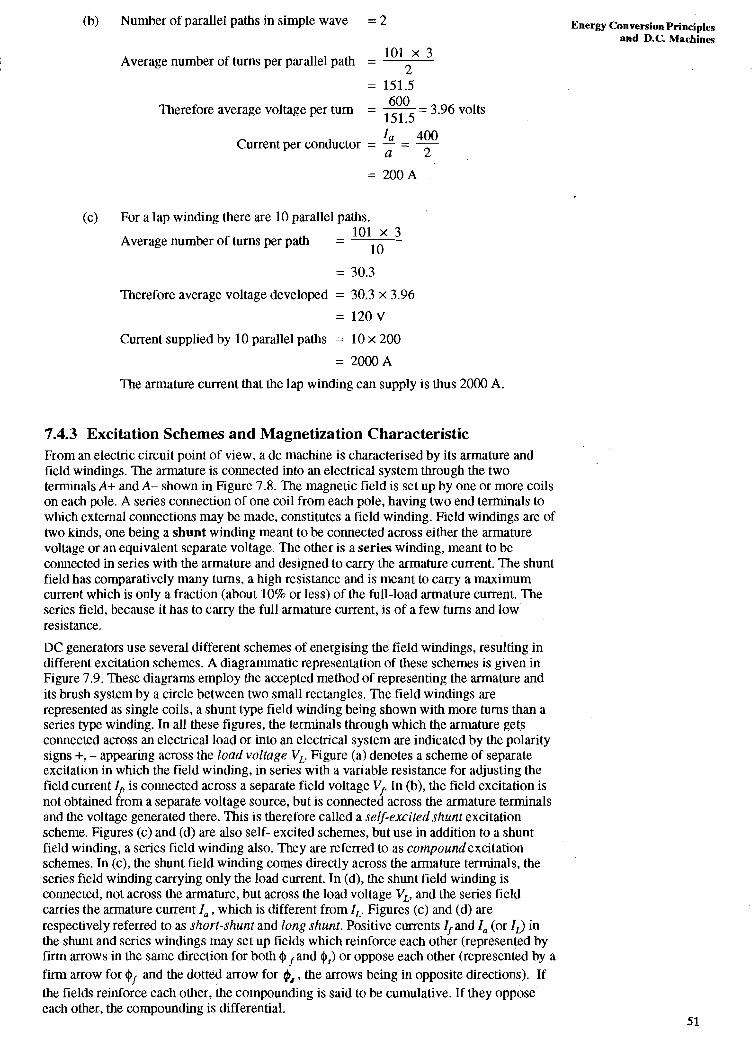
7.4.3 Excitation Schemes and Magnetization Characteristic From an electric circuit point of view, a dc machine is characlerised by ils annature and field windings. The armature is connected into an electrical system through the two terminals A+ and A- shown in Figure 7.8. The magnetic field is set up by one or more coils on each pole. A series connection of one coil from each pole, having two end terminals to whch external connections may be made, constitutes a field winding. Field windings are of two kinds, one being a shunt winding meant to be connected across either the armature voltage or an equivalent separate voltage. The other is a series winding, meant to be connected in series with the armature and designed to carry the armalure current. The shunt field has comparatively many turns, a high resistance and is meant to carry a maximum current which is only a fraction (about 10% or less) of the full-load armature current. The series field, because it has to carry the full armature current, is of a few turns and low resistance.
DC generators use several different schemes of energising the field windings, resulting in different excitation schemes. A diagrammatic representation of these schemes is given in Figure 7.9. These diagrams employ the accepted method of representing the annature and its brush system by a circle between two small rectangles. The field windings are represented as single coils, a shunt type field winding being shown with more turns than a series type winding. In all these figures, the terminals through which the armature gets connected across an electrical load or into an electrical system are indicated by the polarity signs +, - appearing across the load voltage V,. Figure (a) denotes a scheme of separate excitation in which the field winding, in series with a variable resistance for adjusting the field current If is connected across a separate field voltage V/. In (b), the field excitation is not obtained from a separate voltage source, but is connected across the armature terminals and the voltage generated there. This is therefore called a self-excited shunt excitation scheme. Figures (c) and (d) are also self- excited schemes, but use in addition to a shunt field winding, a series field winding also. They are referred to as cornpound excitation schemes. In (c), the shunt field winding comes directly across the armature terminals, the series field winding carrying only the load current. In (d), the shunt field winding is connected, not across the armature, but across the load voltage V,, and the series field carries the armature current la, which is different from I,. Figures (c) and (d) are respectively referred to as short-shunt and long shunt. Positive currents I, and I, (or I d in the shunt and series windings may set up fields which reinforce each other (represented by firm arrows in the same direction for both $ and $,) or oppose each other (represented by a firm arrow for $f and the dotted arrow for @, , the arrows being in opposite directions). If the fields reinforce each other, the compounding is said to be cumulative. If they oppose each other, the compounding is differential.

Electrical Machines & Messwing htnunents
(a) Separate excitation
(b) Shunt excitation
if- - a A. #f
- + - A 1 - s 0 6-- VL 8
I I
(c) Short-shunt compound
-
(d) Long-shunt compound Figure 7.9 : Excitation schemes for D.C. Generators
The "magnetization cqaracteristic" corresponding to the shunt field winding alone is the relationship between the voltage E, induced in the armature at a constant speed and the field current $ From Eq. (7.1 I), this induced voltage is given by
PZ 27t = K N N $ , where KN = - = ---KT a60 60 (7.15)
If the speed is held constant, this voltage is directly proportional to the flux per pole. Now, as the field current is increased, the flux $ will increase approximately linearly for low values of currents, and increase at a slower rate for higher values due to the phenomenon of

magnetic saturation. The magnetisation characteristic at a speed N will be as shown in FigGre 7.10. Since $, the flux per pole is proportional to Ea when Nis constant, to a Energy Conversion Principles
and D.C Machines
, - -- SPEED =kN c-
- --- SPEED SPEED, = N k N
R %
/ - L KNEE
Figure 7.10 : Magnetisation Characteristics
different scale, any one of the curves in Figure 7.10 can also be regarded as relating $ to I/. At a speed kN, the voltage corresponding to each value of I, will be k times the value for speed N, as shown by the dotted curves in the figure. The curved portion of the characteristic is called the "knee" of the curve. The rated voltage is generally selected to be the voltage E,, just above the knee, for the case when N is equal to the rated speed of the machine.
The flux $ per pole is due to the magnetomotive force set up by the field windings. If the shunt field is acting alone, on each pole the magnetomotive force is N, If where N,is the number of turns on a pole. If a series winding is also operating, the current through the coil being I,, , field turns N,, , an additional magnetomotive force N,, I,, would be in operation. The nett magnetomotive force is then (N,If+ N,, I,,), the plus sign corresponding to cumulative action and the minus sign to differential action. This magnetomotive force is Ulerefore equivalent to a current If' flowing through the shunt field winding alone, where
N I + N,, I,, + [ , )={+*(%)i]
Using the value of If' as calculated above, magnetisation characteristics such as those of Figure 7.10 can be utilised for determining the induced voltage in the armature of compound wound generators.
Self-Exci tation On the applicatibn of a voltage Vf across the field circuit, the current Ifflows through the field winding and a flux $ will come into being. So, the process of voltage generation in a separately excited generator is easy to understand. In the self-excited schemes, this is far from clear. This is because, to start with, when the generator is at rest, nolvoltages exist anywhere and so the field current If can only be zero. If we now bring thk armature upto a speed N it is not at all clear if there will be any If at all, and if it exists, what its value will .be. Actually if a shunt generator is being rotated at a speed N, with the switch S in Figure 7.9(b) kept open, and the switch is closed at t = 0, the generator can "self-excite" provided there is some residual magnetism in the irorr Consider the magnetisation characteristic shown in Figure 7.1 1, where we have assumed that there is residual magnetism, i.e, even with I,= 0, a residual voltage E,is induced in the armature at speed N. Let the current If be a function of time I,(t)*.
*. In this discussion we shall make a departure from convention and use capital letter& for the time varying quantities I f (t ) and Ea(t) to facilitate reference to the magnetisation characteristic relating steady state E, to If. I 53

Electrical Machines & Measuring lastmrnents
CURVES FOR WHICH V = If RT
0 * If
Then, the total flux linking the field winding will also be a function of time given by h,(t). The current Ifflowing through the armature will produce a flux linkage h, (t) with the armature. Let the total resistance in the circuit formed by the armature, the field winding and the variable resistance Rfbe Rj-. The flux linkages hf and ha are both stationary in space and so whereas a speed voltage E,(t), related to If (I) by the magnetisation characteristic, is
(l h d 1, produced in the armature, the additional emfs are only the transformer emfs A and -
(it (lt We may regaid the speed voltage as balancing the resistance drop in the circuit and the transformer emfs according to the equation
d h , . d h In practice, - is negligible compared to and we may write
dt dt
Referring to Figure 7.11, if the field current is glven by OA, at time t, Ulen AC = E,(t), AB d h d h
= If RT and so BC corresponds to --f . So, at time t = 0, -2 = E, and so hf must increase. dr dl
This is possible only if the field current if responiihle for producing $increases. So both current If and flux hf increase to new values as t increases. As long as the magnctisation characteristic lies above Ule V = RTlf curve, both If and hf will continue to increase, the rate
d h of increase --f corresponding lo the amount by which E, exceeds RT If at that instant. This
fit rate of increase becomes zero when If= OP, and so this is the final value reached by I f . The armature voltage, after a transient period, has therefore built up from the value .Fr to the value give11 by PQ,. If Rf and therefore RT is increased, the slope of the V = If RT curve ' keeps increasing and the voltage to which the armature builds up will move to the left along - the magnetisation characteristic. Beyond a certain value R, (called the critical resistance)
the built up voltage will abruptly fall to a small value as at Q,.
1; there is no residual magnetism in the field circuit, this build up process can not begin. Also, even if there is residual magnetism, but it is in such a direction that any field current produced by it tends to decrease the original flux, there is reduction i11 Uie voltage arid, therefore the voltage build up process car1 not take place. Further, as we saw earlier, if thc resistance in Ule field circuit exceeds a critic211 value, Ule build up process call only lead to a very slight change in the voltage from the residual voltage. So, we must ensure that thcre is residual flux. Next we must ensure that the resistance in the field circuit is less than the critical value. If despite these two conditions being met, the armature voltage does not build up, this must be because the polarity of Uie residual enlf is in the wrong dircclion. This can

be rectified either by reversing the direction of current flow in the field by interchanging the E n e w anversion Principles
field terminals or by reversing the direction of rotation. and D.C. Machines
Example 7.6
When separately excited, the opencircuit characteristic of a shunt generator at 1500 rpm is given by:
If(A) 0 0.2 0.3 0.4 0.5 0.6 0.7 0.8
E,(V) 6 96 142 180 215 240 258 264
The corresponding graph is given in Figure 7.12
(a) If the shunt field resistance is 100 ohms, what should be the value of external resistance added if the machine is to generate 200 V at (i) 1500 rpm; and (ii) 1200 rpm?
(b) What is the critical resistance at (i) 1500 rpm (ii) 1200 rpm?
Solution
Refer to the graph shown in Figure 7.1 2
(a) (i) Field current required fo generate 200 V at 1500 rpm = 0.45 A 200
Resistance RT required is therefore - = 444.4 R 0.45
Therefore external resistance to be added = (444.4 - 100) = 344.4 R
Figure 7.12 : Graph for Example 7.6 (Speed = 1 500 RPM)

Eleetrid Machines & (ii) 200 V at 1200 rpm is equivalent to - 1500 x 200 = 250 V at 1500 rpm. The Me~slving lmtrmneats 1200
corresponding field current is therefore ( as seen from the graph) 0.65 A.
200 Resistance RT required to yield this current = -
0.65
Therefore external resistance to be added = (307.7 - 100)
= 207.7 i2.
PR 150 (b) (i) Considering the tangent to the graph, the critical resistance RT = - = -
PQ 0.3 = 5 0 0 n
Since the graph corresponds to a speed of 1500 rpm, this is the critical resistance at 1500 rpm.
1200 (ii) If the graph were redrawn for 1200 rpm, all ordinates would reduce to - = 1500
0.8 times their values at 1500 rpm.
Therefore critical resistance corresponding to 1200 rpm = 150 x 0.8
0.3
7.4.4 Load Characteristics By adjusting the field current If in the separately excited generator, or the value of the variable resistance Rfin the case of the self-excited generator. the voltage VL can be adjusted to a desired value (rated value usually) on "no load, i.e., with I,, = 0. If now the load resistance is decreased the load current will increase. When this happens, the load voltage VL will, in general, undergo a change because of armature reaction and armature resistance.
Armature Reaction
When a current I, flows in the armature, a magnetic field is set up which interacts with the magnetic field produced by the current in the field windings. l'his interaction is referred to as armature reaction. When armature current flows in a generator, the direction of current flow is the same as that of the induced voltage rise in the armature conductors. Hence, referring to Figure 7.7(a), the arrows shown represent the directions of current flow also. We find that in all the conductors under the S-pole currents flow from top to bottom, whereas they flow from bottom to top under the N-pole. The action of these currentb is to set up a South polar flux in the interpolar regbn with axis between slots 4 and 5 and a North polar flux in the interpolar region between slots 8 and 1. The effect will be to add to the magnetic field produced by the field windings in the, right half of the polcs and subtract frorgthis flux in the left half of the poles. If the iron did not show any saturation effects, Ihe flux added would be exactly equal to the flux subtxacted, leaving the flux produced per pole by the field windings unaffected. However, because of saturation, the increase in flux in the right half of the poles tends to be less than the decrease, leading to a nett reduction in the flux per pole, the effect being more pronounced at higher values of flux per pole. Figure 7,.13 indicates the manner in which different values of armature current affect the flux per pgle. In the figure we have plotted the flux per pole vs I f ', where If' is the equivalent field cdrrent as given by Eq. (7.16).
1; Figure 7.13 : Effect of Armature Kea~T~on or1 I-lux per Pole

Resistance Drop ELergy Conversion Principles
The induced voltage produced by the motion of the armature in the magnetic field, being and D.C. Machines
proportional to the flux per pole at constant speed, will be influenced by armature reaction. However, this voltage will not be available as the voltage VL across the load because of the voltage drop produced by the armature current flowing through the resistance of the armature and the brush contact (See Seclion 7.3.1). If the induced armature voltage is E,, for generators with separate or shunt excitalion
VL = E, - I, Ra - 2 V, , (7.18 a)
where R, = resistance of the armature winding and leads,
VB = Brush contact voltage drop (- 0.8 to 1.3 V, often taken to be 1 V)
I, = armature current
The term 2VB occurs because in any closed path through the load two brushes will appear in series. For the compound wound machines there is an additional resistance drop I$,,, in the resistance R , of the series winding. Hence, for long-shunt compound generators,
For short-shunt connections I, R,, in the above equation should be replaced by I, R,,.
Load Characteristics
In a separately excited generator being driven at the rated speed by a prime mover, let a field current If, produce the rated voltage Eo on no load. Then, as load current increases from 0, as seen from Figure 7.9 (a), I, = I, also increases. Because of armature reaction, there is an increased reduction in the flux per pole and so the induced voltage falls as given by curve (a) in Figure 7.14. (In this graph, I , is the variable on the x-axis while voltage is the variable on the y-axis). If we neglect the brush contact voltage drop there is a resistance drop I,R,. This has been plotted at the bottom of the figure. From Eq. (7.18a), the terminal voltage V, = E, - I,R, and will be given by curve (b). Curve (a) is referred to as the "internal characteristic" and curve (b) as the "external characteristic" of the separately excited generator.
In the shunt generator (Figure 7.9(b)) for the same rated speed, the same field current If, will induce an armature voltage Eo. However, since I, = If + I,, I, = If for I, = 0. Due to current V, will be slightly less than E, because of armature resistance drop If Ra ev tiS n at no load. So, for VL = Eo , the field current will have to be adjusted to a slightly higher value by varying Rf. Then, as the load current increases, there will be reductions in voltage due to ,, both armature reaction and armature resistance drop. However, since the field current depends on VL for a given field branch resistance as seen from Figure 7.9 (b), unlike the field current in the separately excited machine, Ifdoes not remain constant at its initial value but falls with the voltage. Therefore the external characteristic of the shunt generator will be as seen in curve (c), and lies below the external characteristic of the separately excited generator. The addition of I$, to curve (c) yields curve (a'), which is called the internal characteristic of the shunt generator.
I d 2) Id 11 (a 1 (a' 1 (b 1
Figure 7.14 : Load Characteristics of D.C. Generators

Eloarid Machines & . In the case of the sh~rt-shunt compound generator (Figure 7.9(c)), from Eq. (7.18 b), the Memuring Imtrumed effective field current will differ from the actual field current If and will be given by
I; = [ I j k ) , '+' for cumulative and '-' for differential operation.
As a consequence, the internal and external characteristics of the cumulatively compounded generator will lie above that of the shunt generators, while these will lie below in the case of the differential compound generator. Curves (d,) and (d, ) are typical external characterestics for the case of cumulative compounding. In curve (dl), the terminal voltage at full load is equal to that at no load. and the generator is said to be level compounded. If with cumulative compounding, the external characteristic lies above (dl), (as for curve (d,)), the generator is said to be over compounded. If the curve lies below curve (d,), the generator is said to be under compounded. Curve (e) shows the external characteristic of a differential generator. The characteristics for the long-shunt connection are very similar, marginal differences appearing because the current though the series field winding is (If + Id instead of merely Ic
Example 7.7
A 25 kW, 250 V shunt generator is driven at a speed of 1000 rpm. The armature has 4 poles, and employs 100 coils having 2 turns each, in a simple lap winding. Neglecting brush voltage drop and armature reaction, and taking the resistance of the armature as 0.03 ohms and that of the field circuit as 250 ohms, find the induced emf and the flux per pole at full load, rated voltage.
Solution Refer to Figure 7.9 (b).
25000 - l00A Load current at full load = - - 250
Field current If = 250 250 = 1A
I, = 101 A
Ea = V, + I, R, = 250 + 101 x 0.05 = 255.05 V
2, Total no of conductors = 100 x 2 x 2 = 400
SAQ 5 A compound generator delivers full load power of 50 k W at 250 V to a load. The resistances of armature, shunt field and series field are respectively R,= 0.012 Q, Rf = 62.5 !2 and R, = 0.006 !2. Neglect armature reaction. Find the induced emf in the armature if the contact drop at a brush = 1 V. The generator uses a short shunt connection.
7.5 DIRECT CURRENT MOTORS
DC motors are extremely versatile machines used for driving a variety of devices such as pumps, fans, hoists and vehicles. In a dc generator the speed is fixed by the prime-mover and field conditions are adjusted in order to provide the desired terminal voltage at a particular load current. In a dc motor, on the other hand, the need is to match the speed torque characteristic of the driven device (which constitutes the load on the motor) by adjustment of the field conditions and, if required, the armature voltage. Electric motors may be classified according to their speed-torque characteristics as constant speed,

adjustable speed and variable speed motors. A constant speed motor will maintain a nearly Energy Goversion Principles constant speed at all loads. An adjustable speed motor is one in which adjustments can be and D.C Marhies made to vary the no-load speed of operation over wide-limits, the adjusted speed remaining fairly constant at all loads. A variable speed motor has an inherent capacity to vary its speed with the load, usually, by reducing speed as the torque increases, so that excessive power is not drawn by the motor at high torques. In this section we will learn the characteristics of shunt, compound and series excited dc motors and their speed torque characteristics.
7.5.1 Excitation Schemes for DC Motors As stated in Section 7.4.1, both dc generators and dc motors are built in the same way and have the same constructional features. Further, dc motors employ the same excitation schemes as dc generators. In fact the connection diagrams for separately excited, shunt excited and compound excited dc motors can be readily obtained from those shown in Figure 7.9 by replacing the load voltage V, by supply voltage V,. If the shunt field winding in either Figure 7.9(c) or (d) is disconnected, we will be left with a series excited generator. Series generators are quite uncommon. However, series excited dc motors are widely used in a variety of applications. Figure 7.15 (a), (b), (c) and (d) show dc motor connections for (a) separately excited, (b) shunt, (c) series and (d) short-shunt compound motors. In these figures the supply voltage V, is shown as a dc battery.
- (a) Separately Excited Motor
- (b) Shunt Motor
- (c) Series Motor

(d) Short-shunt Compound Motor
Figure 7.15 : Excitation Schemes For DC Motors
7.5.2 Motoring Action and Speed Equation The transition from generating to motoring action can be readily understood by considering the separately excited dc machine of Figure 7.15 (a). Imagine that the field excitation is held constant and that the shaft is supplied at all times with such a torque that the speed of the motor is also held constant in both magnitude and direction. Under these circumstances. neglecting armature reaction, the induced emf Ea will also remain constant and will be given by Eq. (7.1 1). viz
The annature will generate electrical power if the armature current I, flows out of the positive terminal of the armature. For the polarities shown in the figure for E, and Vs , this can occur only if Vs is smaller than E,. The armature current, (neglecting V, or incorporating its effect in R,) will be, from Eq. (7.18 a)
The electrical power generated in the armature is then Eh,, that absorbed by the supply is VsIu the difference I: I?, being dissipated as heat in the armature resistance. There must be an input of mechanical power at the shaft for conversion into the electrical power generated, implying that the shaft torque must act like a prime-mover torque in the same direction as that of rotation. The armature current, interacting with the magnetic field results in a counter-torque such that the nett torque on the shaft is zero, thus ensuring rotation at a constant speed.
If Vs is gradually increased, the armature current will fall becoming zero when Vs = Ea indicating neither generation nor absorption of power in the armature. Under these circumstances the counter-torque is zero and the shaft torque will be small, being required to overcome merely the frictional torque. Vs = E,, therefore marks the transition from generating to motoring action, for, if V, is increased further, the armature current will reverse direction, flowing out of the positive terminal of Vs into the positive terminal of E, implying that the armature is now absorbing electrical power from the supply voltage Vs. As the direction of the magnetic flux is unchanged, the torque produced by armature current will reverse. This torque is therefore no longer a counter-torque but a motoring torque as it acts in the same direction as that of rotation. Again, for the rotor to run at constant speed, the nett shaft torque must be zero implying that the torque on the shaft must now constitute a braking or load torque. Motoring action requires that Vs is greater than E,. The direction of flow of I, shown in Figure 7.15 (a) and in all other schemes of Figure 7.15, is consistent wiq motoring action.
Speed Equation :
The supply voltage and the magnetic flux per pole, together with the armature current, determine the speed of a dc motor. For motoring aetion, since Vs is greater than Ea, the equation corresponding to Eq. (7.18 a) for generators, for the current reference shown in Figure 7.15 becomes \

for separate or shunt excitation, and
E,= Vs-IaRa-IsRse -2 VB
for series and short-shunt compound excitation.
From Eq. (7.1 I),
Hence, the speed can be calculated as
Energy Conversion Prinaples and D.C Machines
(7.20 b)
PZ where KN = -
60a
Example 7.8
A separately excited dc motor is running in the clockwise direction . What is the effect of (a) reversing the supply Vf alone ; (b) reversing the supply VS alone; (c) reversing both band VS ?
Solution I
The torque reverses in direction if either the direction of the armature current or that I of the magnetic flux reverses.
So, in cases (a) and (b), the direction of the developed torque, and hence that of rotation, reverses, becoming counterclockwise.
In case (c), since the directions of both the armature current and the field reverse together, the direction of the torque, and hence that of rotation, remains unchanged.
SAQ 6 What is the effect of reversing the polarity of the supply voltage on the direction of rotation in the case of the shunt, series and compound motors shown in Figure 7.15? Comment.
SAQ 7 A dc sh nt machine generates an armature voltage of 200 V on no load at 1000 rpm, the fie d current being 2 A. Ths machine is next operated as a shunt motor on a 200 V supply. If the armature resistance is 0.5 a, find the speed of the motor if the supply current is
(i) 5 A
(ii) 50 A
(Neglect armature reaction and'brush, voltage drop).

Electdcd Machims & Mmuring Instrmoene
7.5.3 Shunt Motors Speed-torque Characteristics
Consider a dc shunt motor running at no load on rated voltage with the field current held constant. Under steady conditions the motor will run at a constant speed, the electrically produced driving torque being just sufficient to balance the no load windage and friction torque acting on the rotor. As seen from Eq. (7.14), for a constant flux the torque is proportional to the armature current. So, the no load armature current of tlie motor will be quite small, being ideally equal to zero. On a mechanical load being suddenly applied to the shaft, since the driving torque due to armature current is quite small, there will be a braking torque on the shaft causing the motor to decelerate and slow down. As the motor slows, the counter-emf (Eq. (7.15)), being proportional to speed at constant flux, will reduce. This in lum from Eq. (7.20 a), results in an increased armature current and increased driving torque. Finally, a new steady state will be reached at a lower speed with a higher armature current such that the nett torque on the rotor is once again zero. The speed-torque characteristic of the shunt motor thus has a drooping characteristic as shown in Figure 7.16. As seen earlier, armature reaction leads to a further decrease of the flux per pole because of tnagnetic saturation. Calculation of the speed on load, neglecting armature reaction, has already been illustrated in SAQ 7: Example 7.9 further illustrates the calculation of torque, again neglecting armature reaction. The reduction with load of the flux per pole caused by armature reaction will lead to increased speed and armature current for a particular load. Example 7.10(b) requires calculations which take this flux reduction into account.
CURVE
SPEED NEGLECTING
I ARM-REACTION I
I FULL LOAD TORQUE I/ TORQUE
Figure 7.16 : Speed torque curve of a shunt motor
Example 7.9
A 20 kW, 250 V shunt motor has an armature resistance of 0.3 C2 and shunt field circuit resistance of 100 a. At no load and rated voltage the speed is 1500 rpm, the armature current being 5 A.
If the full load line current of the supply is 90 A, find
(i) the full-load speed and
(ii) the developed torque.
Neglect armature reaction and brush contact drop.
Solution
Refer to Figure 7.15(b)
250 Field current If = - = 2.5 A 100
At no load, Ea = 250 - 0.3 x 5 = 248.5 V
= KNQOX 1500
Therefore KN,Qo = - z:i - - 0.1657
At full-load, armature current I, = (IS -If) = (90 - 2.5) = 87.5 A
Therefore Ea = 250 - 0.3 x 87.5 = 250 - 26.25 = 223.75 V
= KN Qo NL where NL = speed on load.
E, - (i) Therefore NL = - - --- 223'75 - - 1350.3 rpm KN Qo 0.1657

27c (ii) Also, as shown in the text, KN = -KT 60
60 Therefore = - KN @o = x 0.1657 = 1.5823.
27c 27c
Therefore full load torque TL = 1.5823 I , = 1.5823 x 87.5
= 138.45 Nm
Starting In order to ensure low losses and good efficiency, the voltage drop at full load due to armature resistance and brush contact is designed to be just a few percent of the rated voltage. When the motor is at standstill, no counter-emf will be generated in the armature. Consequently if full voltage is applied to the armature of a stationary motor, very heavy armature currents will flow, causing damage to the commutator and the armature winding. To prevent this, a starter is required to be used in order to ensure that the armature current does not exceed about twice full load current during the starting process. Essentially, the starter introduces a resistance in series with the armature such that the initial current is restricted. Because of this starting current the motor accelerates from zero speed, and a counter-emf appears reducing the armature current. In a commercial starter, the series resistance is cut out in steps and finally eliminated altogether when the machine comes up to full speed. A more detailed description of a commercial starter is presented in Unit 9, Section 9.5.
Stopping When a large dc motor is coupled to a heavy inertial load, if the supply is merely switched off, the motor may take an hour or more to come to a stop. Such a long period for stopping is often unacceptable and it becomes necessary to apply a braking torque to ensure a quick stoppage. Electrical methods of achieving this include (a) dvnamic braking and (b) plugging, in both of which the field is kept energised and the armature is made to carry a current in a direction opposite to normal so that a braking torque is produced. A brief discussion of these methods is also presented in Unit 9. Section 9.5.
Speed Control The speed of a dc motor is given by Eq. (7.21), repeated below :
Energy Conversion Principles and D.C. Machines
Speed control can be effected by (i) armature control, wherein the flux is held constant and E, is varied, (ii) field control, where the armature voltage is held constant and the field current is varied or (iii) by a combination of the two.
In armature control, one practical way of changing E, is to alter the armature supply voltage Vs. In the Ward-Leonard method of control, illustrated in a rudimentary form in Figure 7.17, Vs is varied by connecting the annature of the motor M to be controlled to the armature of a variable voltage dc generator G. The field current of the generator can be varied from zero to a maximum value in either direction. By this means the generator voltage can be made to vary from zero to maximum with any polarity. Even if the field current of the motor is kept fixed, the variable nature of the generator voltage makes it possible to run the motor from zero speed to a maximum value in either direction. Varying the field current gives an additional method of control.
Figure 7.17 : Ward-Leonard Method

Electrical Machines & Memuring ~ ~ e a C s
In field control, the flux $ is varied by controlling the field current. Referring to Figure 7.1 5 (b), this is quite simply effected by changing the resistance of the field rheostat Rf shown in the figure. If the field current is abruptly reduced by a small amount, the induced emf will also reduce abruptly by a small amount. However, the
Vs - VB - Ea armature current given by I, = will increase by a much higher R,
percentage resulting in increased torque. This will cause the motor to speed up, increasing the emf and reducing the armature current and accelerating torque, a higher value of steady speed being finally attained.
Applications For a fix@ field current, the shunt motor is essentially a constant speed motor whose speed drops by 5 to 15% from no load to full load. The no load speed can be adjusted by varying the field current, the amount of adjustment possible depending on the manufacturer's design specification. Because of its good speed regulation, the shunt motor is used for applications requiring approximately constant speed service such as in line shafts, milling machines, individual drives for lathes, centrifugal pumps, conveyors, fans etc.
Example 7.10
The magnetisation characteristic for the shunt winding of a dc motor is the same aq that given in Figure 7.12 of Example 7.6. When delivering full load, the shunt motor draws an armature current of 20 A from a 230 V supply, the field current being held constant at 0.5 A.
(a) Find the speed and developed torque at full load, given that the armature resistance is 0.75 R. Neglect armature reaction.
(b) Find the actual speed and developed torque if armature reaction reduces the flux per pole'by 7%.
Solution
Refer to Figure 7.15(b).
(a) From the graph, the emf induced at 1500 rpm by a field current of 0.5 A = 215 V.
On full-load, the induced emf in the armature,
E, = (230 - 20 ?< 0.75) = 215 V.
~ e n c e the speed is 1500 rprn neglecting armature reaction effect.
21 5 K N $ o = - a
60 215 1 500
, therefore KT oo = - x - 2n 1500
60 215 x20=27.4Nm Therefore torque = KT Oola = - x -
271 1500
(b) Let the flux per pole, taking armature reaction into account be (o. Then,
$0 = 0.93 4,.
The new value of KN (b - 21 5 - x 0.93
'1500 - 1612.9 rpm The new speed = - - 0.93
The new torque = 0.93 x 27.4 = 25.5 Nm.
7.5.4 Series Motors In a series motor, the flux per pole $ is established by the armature current which flows through it. If there were no magnetic saturation, this flux would be directly proportional to armature current and could be represented as 0 = KI, . The torque in this case would be given by T = KAIa = K~KI:, and would be parabolic in shape. However, because of saturation, as I, increases 0 will increase at a slower rate. On a constant voltage'supply V, to the motor, E, will decrease from V, for zero armature current to slightly less than V, at full load. If we treat E, as approximately constant, the speed N given by

will yield a speed-armatde current characteristic which is a hyperbola. Figure 7.18 gives Energ w v e * M n d r k
the torque-current and speed-current curves of a series motor. In the figure, dotted curves and D.c Machines
are theoretical curves which neglect the effect of saturation while the firm lines give the actual curves. Figure 7.19 illustrates the speed-torque curve of the series motor.
When a series motor is operated from a constant supply voltage, its speed at light loads is very much larger than at full load, the speed dropping rapidly as the torque increases. In fact, on no load the speed will be dangerously high (theoretically infinite), and hence series motors should not be allowed to function on no-load.
Figure 7.18 : N, T vs I, of a D.C. Series Motor
I C
RATED 7 TORQUE
Figure 7.19 : Torque-speed Curve of a L).C. Series Motor
The speed-torque characteristic of a series motor is excellent for traction, as the large value ,' ' of armature current when the annature is at standstill provides a large starting torque and quick acceleration. Also, under steady operating conditions increased torque is met by decreased speed. In electric traction this means that the motor will automatically slow down when climbing up a gradient, and run at good speed on level ground. Series motors are also used in cranes and hoists, where light loads will be lifted quickly and heavy lopds slowly. Series motors are also used in devices which must run at high speeds on light loads.
The starting motors used in automobiles are also series motors.

Elect-ticd Machines ,% S AQ 8 Memuring Imirumen'q
A series motor has a magnetisation characteristic at 1500 rpm given by
E,(V) 6 96 142 180 216 240 258 264
The resistance of the annature is 0.5 Q and of the series field also 0.5 Q.
On a supply of 230 V, the motor is found to draw an armature current of 20 A at full-load. Find the speed and developed torque (a) at full-load; (b) when the arm& current is 10 A.
7.7.5 Compound Motors Compound motors may be connected in long shunt or short shunt as in generators. (The long shunt connection is not shown explicitly in Figure 7.15). As in generators, a compound motor is said to be cumulatively compounded if the magnetomotive forces of the series and shunt windings aid each other, the compounding being diflerentinl when they oppose each other. Since the flux per pole 41 increases with load in a cumulatively compounded motor, the speed will fall more rapidly with load than with shunt excitation alone. Like a series motor, though to a lesser extent, high starting currents will enable the motor to gencrate higher starting torques than the shunt motor, and increasing torque will make the speed drop more rapidly.
A differentially compounded motor, as the flux per polc reduces with increasing armature current, can provide a rising speed- torque characteristic. If a small number of series turns are used, it is possible to ensure that the no load and full load speeds are equal, producing a motor which has a more nearly constant speed than the shunt motor. However differcntial motors are rarely used because of the risk of dangerously high speeds in the event of an accidential overload in which thc scrics field magnetomotive force becomes large enough to cancel the shunt field resulting in vkry small flux per pole.
For comparison, speed-torque characteristics of compound motors are shown along with those of series and shunt motors in Figure 7.20.
SPEE
I I C TORQUE
Figure 7.20 : Speed-torque Curves of I1.C. Motors
RON
A compound motor with a strong series field has a widely variable speed and, when a large torque demand of short duration occurs, it decreases its speed much more than a shunt motor and thus allows its kinetic energy to help carry the load. This effect cm be increased by increasing the inertia of the motor by adding a flywheel. Such motors are common in punch presses where the motor slows down slightly during its power stroke, thc kinetic energy stored in the flywheel doing most of the work. Between punching operations, the motor brings the flywheel back to normal speed. Compound motors are also used wherever slightly variable speed is an advantage as in rolling mills. Sometimes they are also used in

hoists and elevators where quick starting (provided by the series field) is followed by a E n e w Conversion Principles fairly long period where a fairly constant speed is required, during which time the series and D.C. Machines
field can be removed from operation by short-circuiting it.
7.6 SUMMARY
The extensive use of electrical generators and motors was emphasized in Section 7.1, which introduced the Unit. In Section 7.2 you were introduced to Faraday's law of induction and the Blv rule for computing emf in generators and back-emf in motors. You next learnt to use the Rli rule to compute forces on conductors as also torque in motors and counter-torque in generators.
In Section 7.3, you learnt about copper losses, iron losses and mechanical losses in electrical niachiiies and their important role in causing temperature rise and fixing the efficiency and rating of electrical machines.
After a brief introduction to the constructional features of dc machines, you leamt'in Scction 7.4 how to calculate the emf and torque in armatures having simple lap or wave-windings. The Section also considered shunt, series and compound schemes of excitation of generators, magnetization characteristics and load characteristics taking armature resistance and armature reaction into account. Section 7.5 dealt with motoring action, the speed equation of dc motors and their torque-speed characteristics.
7.7 ANSWERS TO SAOs
SAQ 1
At any frequencyi B, = 1.2 cos 2nft cos 5m, for B, = 1.2 teslas, and z = 0.4 m.
(a) Substituting the values given in SAQ 1 into Eq. (7.4).
x (t, xI, x2) = X O e 4 x 1.2 {sin 5m2 - sin 5m1)
-- - 0'024 {sin 5 m2 - sin 5m1 n
ah (i) e, = -
at = 0
ax 3 ax dx2 (ii) e,,, = -- + - . - dxl - dx2 = 20 ds
axl . dt ax2 dt . Here - - -
/ dr dt
I ,
O.OM x 5n { cos5n (201 + 0.2)- cos 5n (201) x 20 Therfore em = - 'It
i = - 4.8 cos 100nt.
The same result could alternatively be obtained using Blv and the right hand rule.
(iii) Since there is no transformer emf, em = the total emf.
O.OM cos 1 O O ~ { sin 5m2 - sin 5ml 1. (b) Here A. (t, XI, x2) = - n
(1) e, = - a' = - 4'0M x 1 OOn sin 1 OOnt { sin (1 00nt + n ) - sin 100nt) at
= -2.4 sin 100nt x (-2 sin 100trt)
= 4.8 sin2 1 OOnt
a3L dx1 a3L h 2 (ii) em = - - + - - axl dt ax2 dt
-- - OaoM cos L O O ~ t { 5n cos 57~x2 - 5n cos5ml x 20 n
= 2.4 cos100nt{cos(100nt + n )- cos 1OOnt)
= - 4.8 cos2100nt

Electrical Machines & \
Mesclwing btromeots (iii) Therefore total emf = e, + en, = - 4.8{cos2100nt - sin2100nt)
= - 4.8 cos200nt.
Alternatively, since xl and x2 are functions of t, we could express h entirely as a function of t alone:
h(t) = - 0024 cosl OOnt { sin(100nt + n) - sin 1 Mht n
-- - cos100 nt . sin100 nr = - - n
0.024 sin 200 nt n
Therefore = - x 200n cos2OO nt = - 4.8 cos 200nt, as before. dt n
SAQ 2
(a) (i) F = 0.2 x 500 x 1 = 100 N
(ii) Using Fleming's left-hand rule, F is in the positive z-direction.
(iii) Using the left-hand rule, F is in the negative z-direction.
(b) From the Bil = F formula,
F B = - = 80 il 1200 x 0.5
= 0.133 tesla
SAQ 3
Total losses = 3.5 + 1.5 = 5 kW.
(c)
SAQ 5
Power supplied by the prime mover = Output power + losses = 105 kW
If prime-mover torque is T Nm, and w, is the speed of the rotor in radians per second, power output of prime-mover = w,T watts.
- 27Ch' 2 n x 1ooo=104.72rad/s If N = speed in rpm, w, = --- - 60 60
Therefore 105,000 = 104.72 T
Output 100 - 0.952 Efficiency = - -- -
Input 105
Mechanical power output = { 100 -(3.5 + 1.5)) = 95 kW
w, = 104.72 rads
Therefore T = - 95'000 - - 907.2 Nm 104.72
u ut Efficiency = = $ = 0.95 Input
Figure for A~lswer to SAQ 5

I Refer to the figure given. L
509000 - 200 A Load current IL = - - 250
Energy (&version ~ r i n c i ~ l e s and D.C Machines
Terminal voltage at the armature = VL + I,& = 250 + 200 x 0.006
= 251.2 V I
Current through shunt field If = - 251'2 - - 4.02 A I
62.5
Therefore armature current la = 200 + 4.02 = 204.02 A I Armature resistance drop I S , = 204.02 x 0.012 = 2.45 V
Brush voltage drop through 2 brushes in series = 2 V
Therefore induced armature emf = 25 1.2 + 2.45 + 2
= 255.65 V
SAQ 6
Reversing the polarity of the supply voltage reverses the directions of both the armature and field currents in all three cases. Consequently, since the directions of both armature current and the magnetic flux reverse together, the direction of the developed torque remains unchanged.
If the direction of rotation is to be reversed, additional switching arrangements must be provided to ensure that, on reversing either the armature or the field current, the other continues to flow in its original direction.
SAQ 7
When operated as a generator, I, = IL + If and E, = VL + I,&.
On no-load, I, = If = 2 A; E, = 200 + 2 x 0.5 = 201 V .
(i) As a motor, Ea = Vs - I,Ra, la = (Is - I f ) = 5 - 2 = 3 A
Therefore Ea = 200 - 3 x 0.5 = 198.5 V .
Since the field current both as a generator and a motor is the same, Ea is pdoportional to speed.
198.5 x1000=987.6rpm So, speed when Is = 5 A is - 201
(ii) ForIs=50A, Ia=50-2=48A
Therefore Ea = (200 - 48 x 0.5) = 176 V
Therefore speed = x 1000 = 875.6 rpm 201
SAQ 8
(a) When the armature current is 20 A, the induced emf Ea in the armature is given by E, = 1230 - 20 x (0.5 + 0.5)) = 210 V
At 1500 rpm, we find from the magnetization characteristic that 20 A induces an emf of 216 V. For the same current to produce an induced emf of 210 V, the speed of the motor should be
From Eqs. (7.12) and (7.14), we obtain
T = - Ea ' x 60 = 27.5 Nm. 27th'
(b) The induced emf in the armature is now (230 - 10 x 1 ) = 220 V .
At 1500 rpm, 10 A induces an emf of 120 V. 220
Therefore speed of motor = - x 1500 = 2750 rpm. 120
Torque T = 220x lo x 60 = 7.6 Nm. 2n x 2750