unit i basics of communication - mr.rajiv bhandari by prof. prashant lahane figure 1.1 components of...
TRANSCRIPT
Data
Communications
Unit I – Basics of Communication
Prepared By Prof. Prashant Lahane
DATA COMMUNICATIONS
• The term telecommunication means communication at
a distance.
• The word data refers to information presented in
whatever form is agreed upon by the parties creating
and using the data.
• Data communications are the exchange of data
between two devices via some form of transmission
medium such as a wire cable.
Prepared By Prof. Prashant Lahane
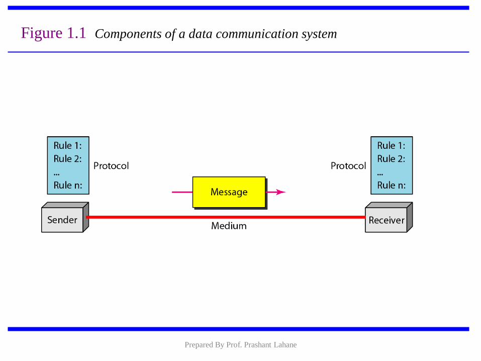
Figure 1.1 Components of a data communication system
Prepared By Prof. Prashant Lahane
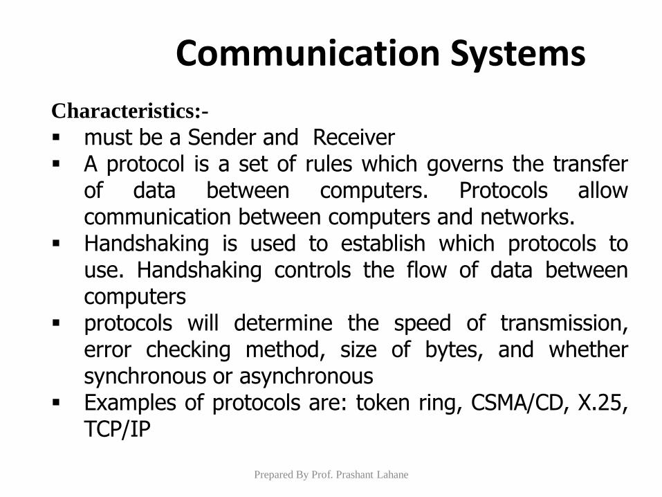
Characteristics:-
must be a Sender and Receiver A protocol is a set of rules which governs the transfer
of data between computers. Protocols allow communication between computers and networks.
Handshaking is used to establish which protocols to use. Handshaking controls the flow of data between computers
protocols will determine the speed of transmission, error checking method, size of bytes, and whether synchronous or asynchronous
Examples of protocols are: token ring, CSMA/CD, X.25, TCP/IP
Communication Systems
Prepared By Prof. Prashant Lahane
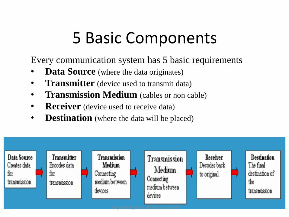
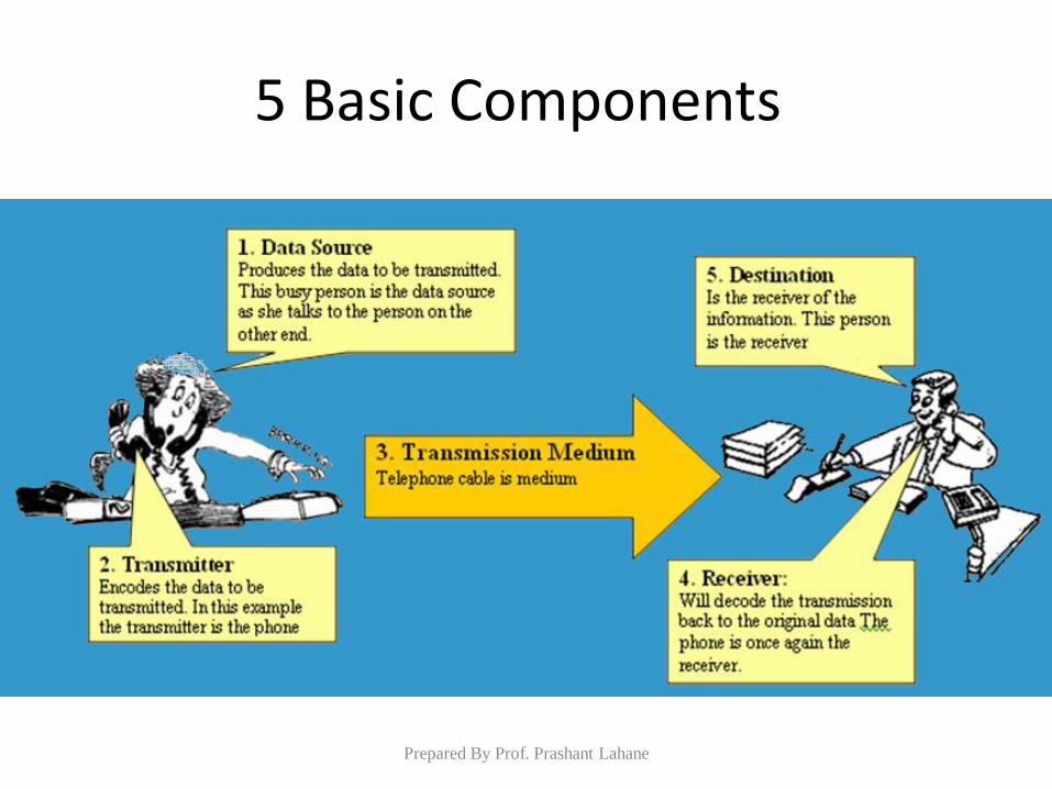
5 Basic Components Every communication system has 5 basic requirements
• Data Source (where the data originates)
• Transmitter (device used to transmit data)
• Transmission Medium (cables or non cable)
• Receiver (device used to receive data)
• Destination (where the data will be placed)
Prepared By Prof. Prashant Lahane
5 Basic Components
Prepared By Prof. Prashant Lahane
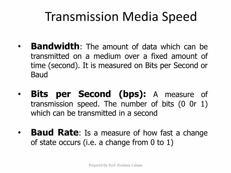
• Bandwidth: The amount of data which can be
transmitted on a medium over a fixed amount of time (second). It is measured on Bits per Second or Baud
• Bits per Second (bps): A measure of
transmission speed. The number of bits (0 0r 1) which can be transmitted in a second
• Baud Rate: Is a measure of how fast a change
of state occurs (i.e. a change from 0 to 1)
Transmission Media Speed
Prepared By Prof. Prashant Lahane
Transmitting and Receiving in Communication Systems
Prepared By Prof. Prashant Lahane
Any transmission May be:
•analog or digital
•Serial or parallel
Communication Concepts
Prepared By Prof. Prashant Lahane
Sender transmitted
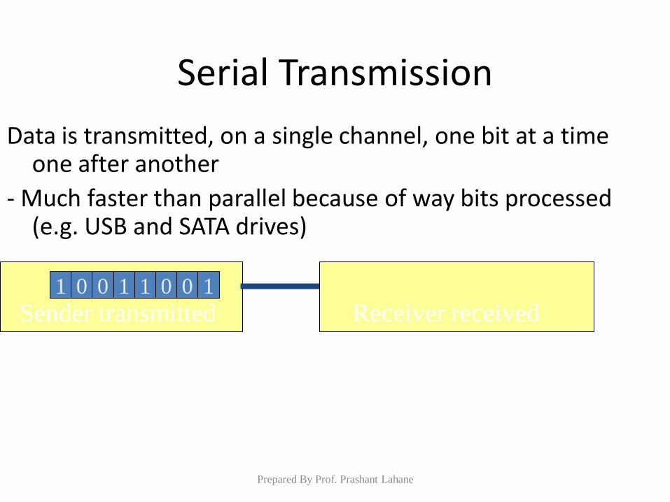
Serial Transmission
Data is transmitted, on a single channel, one bit at a time one after another
- Much faster than parallel because of way bits processed (e.g. USB and SATA drives)
Receiver received 1 0 1 0 0 1 1 0
Prepared By Prof. Prashant Lahane
Rec
eiv
er r
ecei
ved
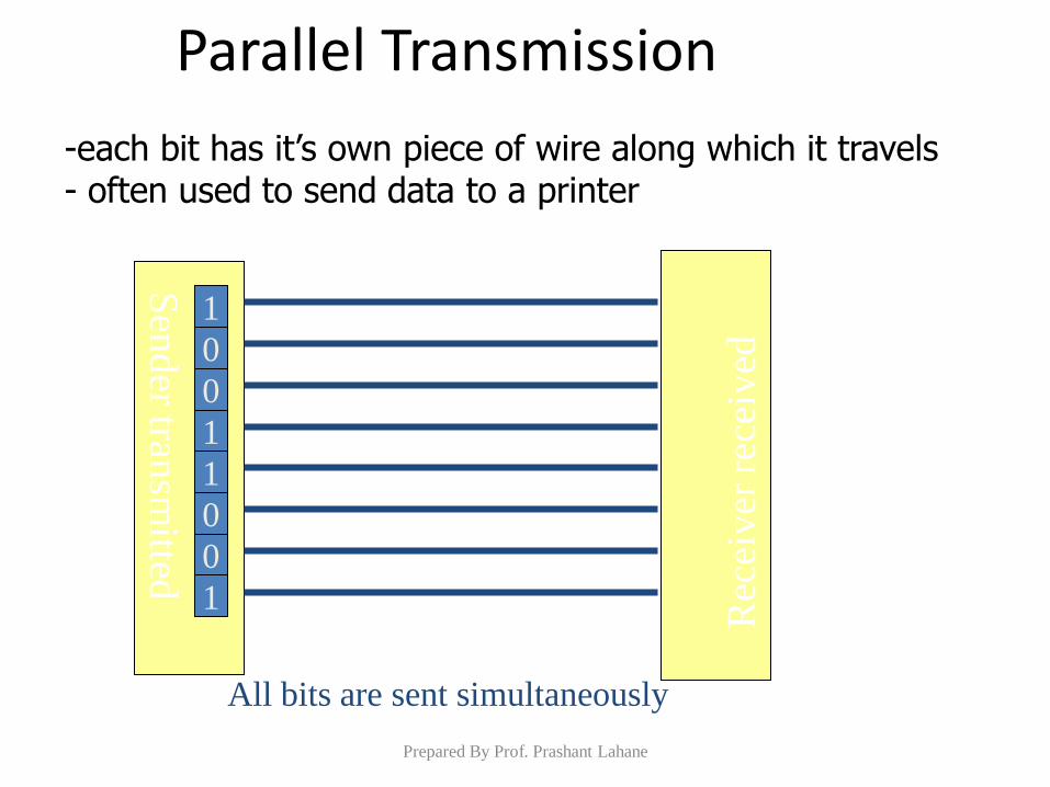
-each bit has it’s own piece of wire along which it travels - often used to send data to a printer
Parallel Transmission
Sen
der tran
smitted
All bits are sent simultaneously
1
0
0
1
1
0
0
1
Prepared By Prof. Prashant Lahane
Why Not use Parallel Instead of serial?
• Due to inconsistencies on channels data arrives at different times
• Because of the way it is transmitted packet switching cannot be used
• The above two points makes parallel slower than serial and requires higher bandwidth.
• Parallel transmissions are rarely used anymore
Prepared By Prof. Prashant Lahane
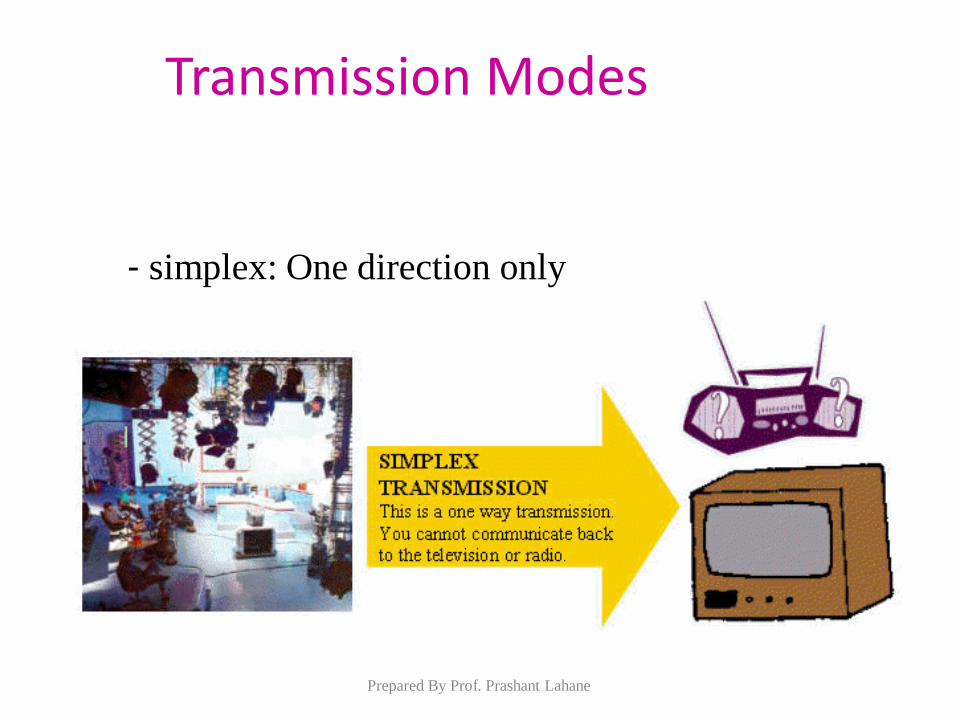
- simplex: One direction only
Transmission Modes
Prepared By Prof. Prashant Lahane
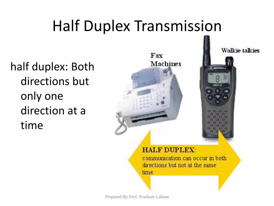
Half Duplex Transmission
half duplex: Both directions but only one direction at a time
Prepared By Prof. Prashant Lahane
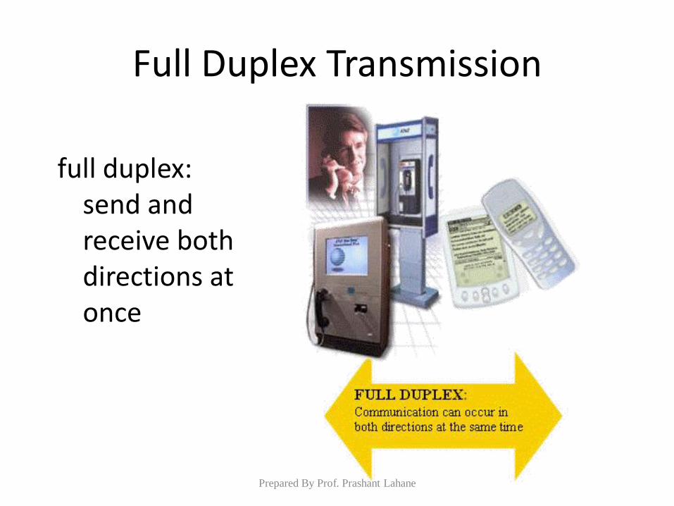
Full Duplex Transmission
full duplex: send and receive both directions at once
Prepared By Prof. Prashant Lahane
ANALOG-TO-DIGITAL CONVERSION
• A digital signal is superior to an analog signal
because it is more robust to noise and can easily be
recovered, corrected and amplified.
• For this reason, the tendency today is to change an
analog signal to digital data.
• There are two techniques, pulse code modulation
and delta modulation.
Prepared By Prof. Prashant Lahane
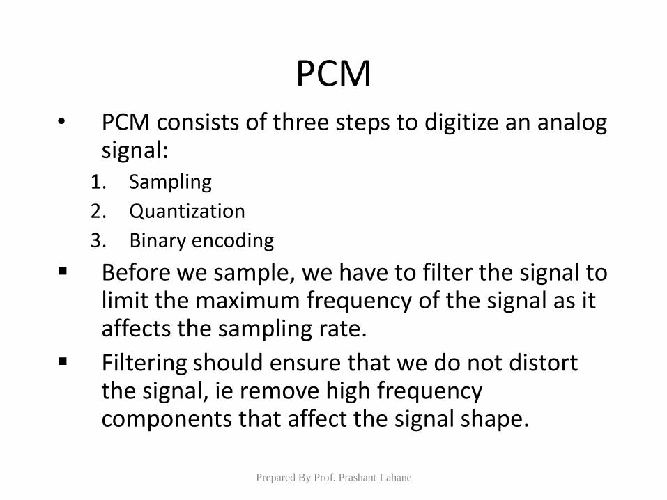
PCM • PCM consists of three steps to digitize an analog
signal: 1. Sampling
2. Quantization
3. Binary encoding
Before we sample, we have to filter the signal to limit the maximum frequency of the signal as it affects the sampling rate.
Filtering should ensure that we do not distort the signal, ie remove high frequency components that affect the signal shape.
Prepared By Prof. Prashant Lahane
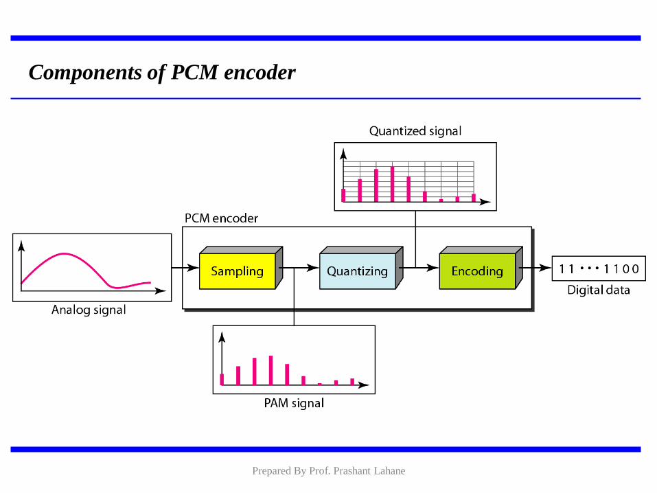
Components of PCM encoder
Prepared By Prof. Prashant Lahane
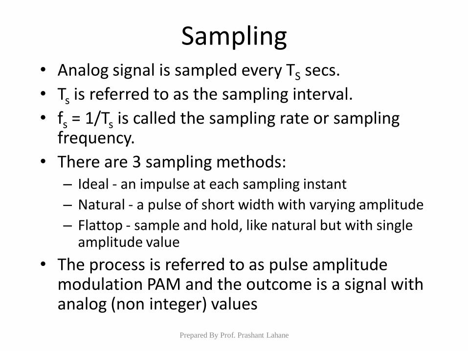
Sampling • Analog signal is sampled every TS secs.
• Ts is referred to as the sampling interval.
• fs = 1/Ts is called the sampling rate or sampling frequency.
• There are 3 sampling methods: – Ideal - an impulse at each sampling instant
– Natural - a pulse of short width with varying amplitude
– Flattop - sample and hold, like natural but with single amplitude value
• The process is referred to as pulse amplitude modulation PAM and the outcome is a signal with analog (non integer) values
Prepared By Prof. Prashant Lahane
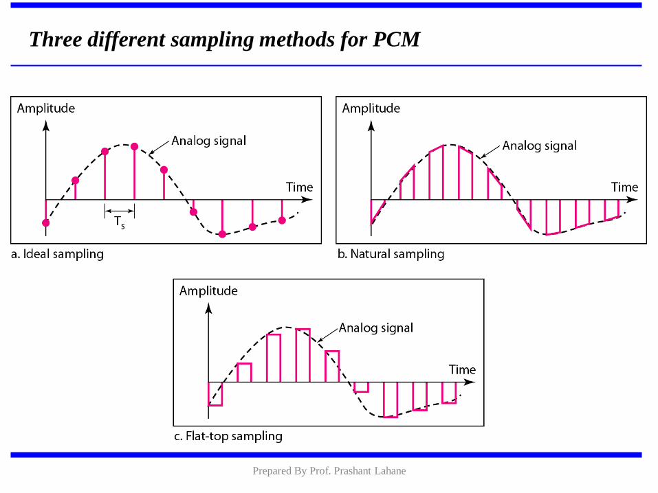
Three different sampling methods for PCM
Prepared By Prof. Prashant Lahane
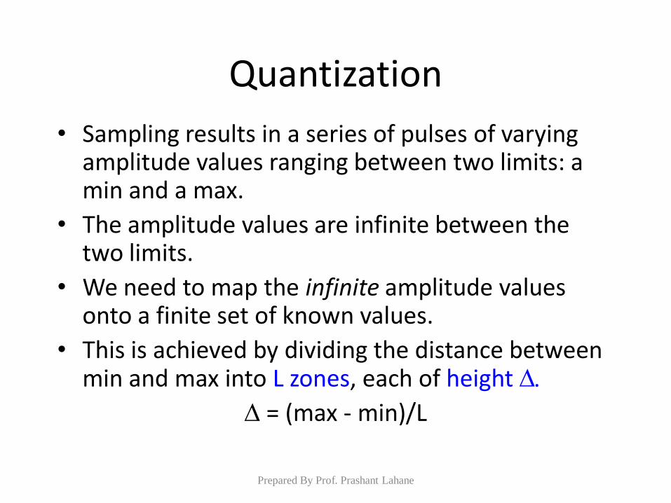
Quantization
• Sampling results in a series of pulses of varying amplitude values ranging between two limits: a min and a max.
• The amplitude values are infinite between the two limits.
• We need to map the infinite amplitude values onto a finite set of known values.
• This is achieved by dividing the distance between min and max into L zones, each of height
= (max - min)/L
Prepared By Prof. Prashant Lahane
Quantization Levels
• The midpoint of each zone is assigned a value from 0 to L-1 (resulting in L values)
• Each sample falling in a zone is then approximated to the value of the midpoint.
Prepared By Prof. Prashant Lahane
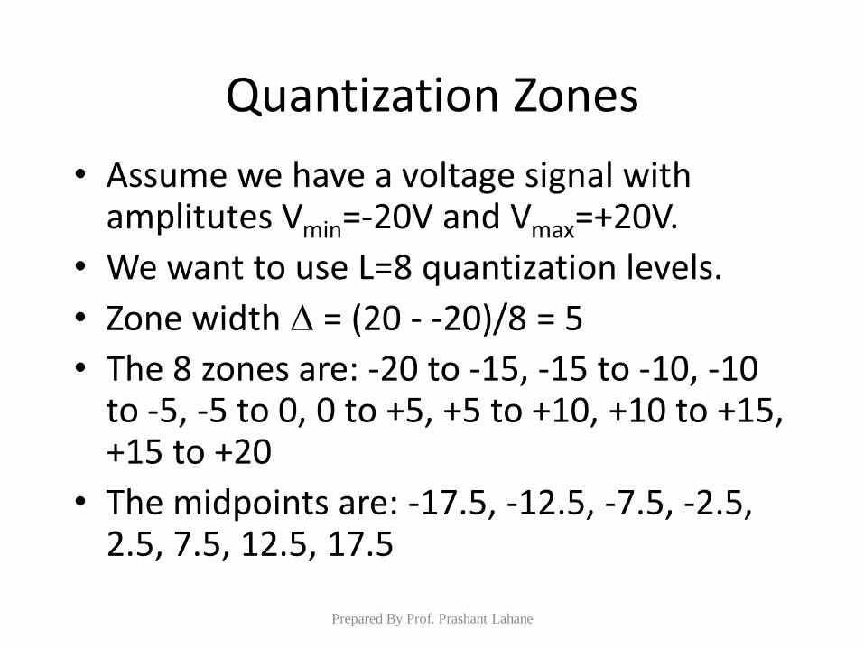
Quantization Zones
• Assume we have a voltage signal with amplitutes Vmin=-20V and Vmax=+20V.
• We want to use L=8 quantization levels.
• Zone width = (20 - -20)/8 = 5
• The 8 zones are: -20 to -15, -15 to -10, -10 to -5, -5 to 0, 0 to +5, +5 to +10, +10 to +15, +15 to +20
• The midpoints are: -17.5, -12.5, -7.5, -2.5, 2.5, 7.5, 12.5, 17.5
Prepared By Prof. Prashant Lahane
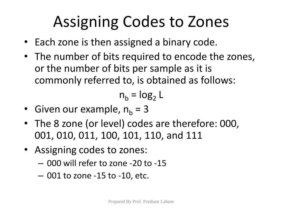
Assigning Codes to Zones • Each zone is then assigned a binary code.
• The number of bits required to encode the zones, or the number of bits per sample as it is commonly referred to, is obtained as follows:
nb = log2 L
• Given our example, nb = 3
• The 8 zone (or level) codes are therefore: 000, 001, 010, 011, 100, 101, 110, and 111
• Assigning codes to zones: – 000 will refer to zone -20 to -15
– 001 to zone -15 to -10, etc.
Prepared By Prof. Prashant Lahane
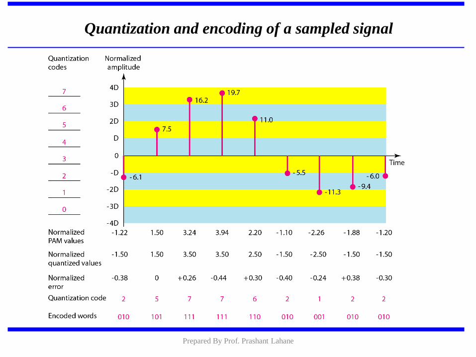
Quantization and encoding of a sampled signal
Prepared By Prof. Prashant Lahane
Quantization Error • When a signal is quantized, we introduce an error
- the coded signal is an approximation of the actual amplitude value.
• The difference between actual and coded value (midpoint) is referred to as the quantization error.
• The more zones, the smaller which results in smaller errors.
• BUT, the more zones the more bits required to encode the samples -> higher bit rate
Prepared By Prof. Prashant Lahane
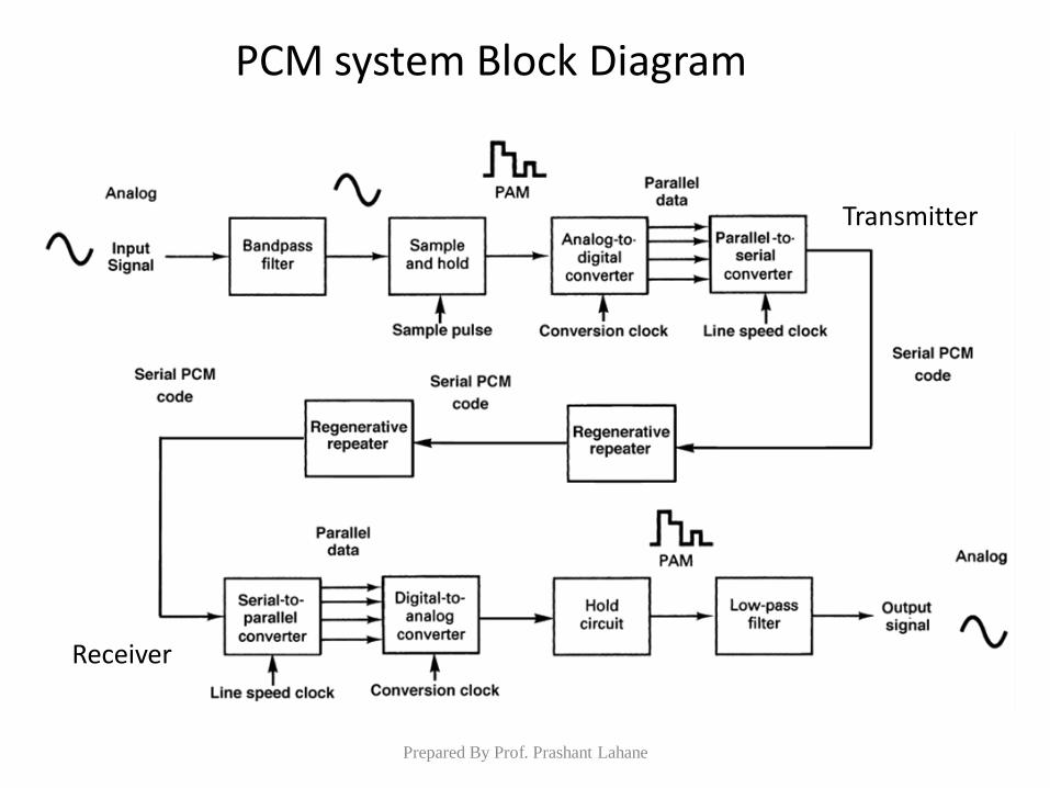
PCM system Block Diagram
Transmitter
Receiver
Prepared By Prof. Prashant Lahane
PCM Decoder
• To recover an analog signal from a digitized signal we follow the following steps:
– We use a hold circuit that holds the amplitude value of a pulse till the next pulse arrives.
– We pass this signal through a low pass filter with a cutoff frequency that is equal to the highest frequency in the pre-sampled signal.
• The higher the value of L, the less distorted a signal is recovered.
Prepared By Prof. Prashant Lahane
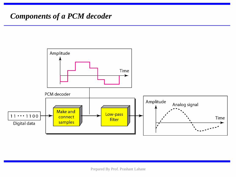
Components of a PCM decoder
Prepared By Prof. Prashant Lahane
Delta PCM (DPCM)
• Instead of using one bit to indicate positive and negative differences, we can use more bits -> quantization of the difference.
• Each bit code is used to represent the value of the difference.
• The more bits the more levels -> the higher the accuracy.
Prepared By Prof. Prashant Lahane
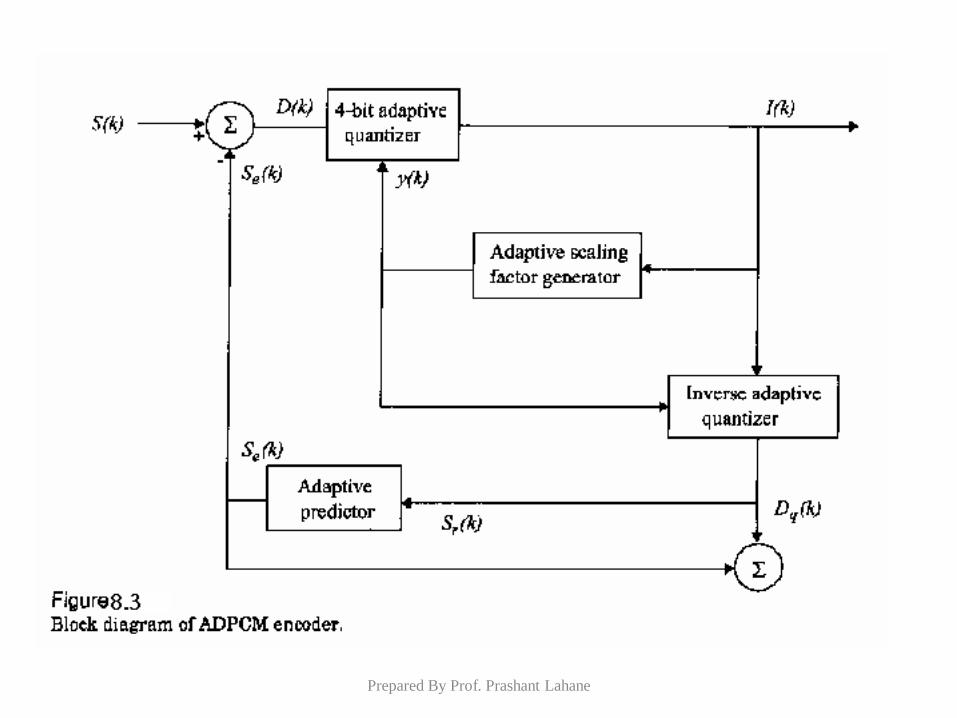
Adaptive Differential Pulse Code
Modulation (ADPCM)
• More efficient than PCM by removing the redundancies in the speech signal.
• Adjacent samples of a speech waveform are highly correlated.
• This means that the variance of the difference between adjacent speech amplitudes is much smaller than the variance of the speech signal itself.
Prepared By Prof. Prashant Lahane
ADPCM
• Allows speech to be encoded at a bit rate of 32 kbps, while retaining the same voice quality.
• In practice, ADPCM encoders are implemented using signal prediction techniques.
Prepared By Prof. Prashant Lahane

ADPCM
• Instead of encoding the difference between adjacent samples, a linear predictor is used to predict the current sample.
• The difference between the predicted and actual sample called the prediction error is then encoded for transmission.
• Prediction is based on the knowledge of the autocorrelation properties of speech.
Prepared By Prof. Prashant Lahane
Prepared By Prof. Prashant Lahane
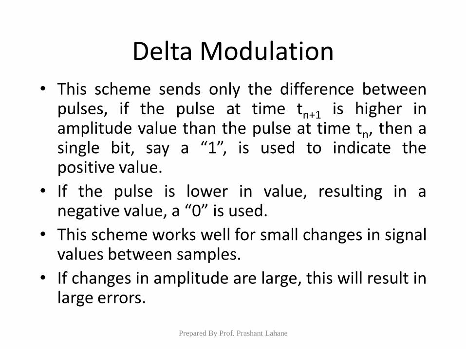
Delta Modulation • This scheme sends only the difference between
pulses, if the pulse at time tn+1 is higher in amplitude value than the pulse at time tn, then a single bit, say a “1”, is used to indicate the positive value.
• If the pulse is lower in value, resulting in a negative value, a “0” is used.
• This scheme works well for small changes in signal values between samples.
• If changes in amplitude are large, this will result in large errors.
Prepared By Prof. Prashant Lahane
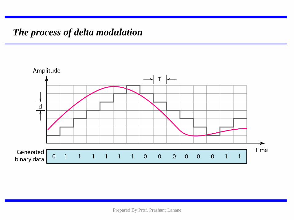
The process of delta modulation
Prepared By Prof. Prashant Lahane
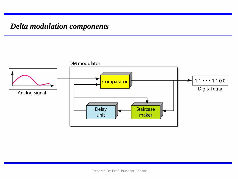
Delta modulation components
Prepared By Prof. Prashant Lahane
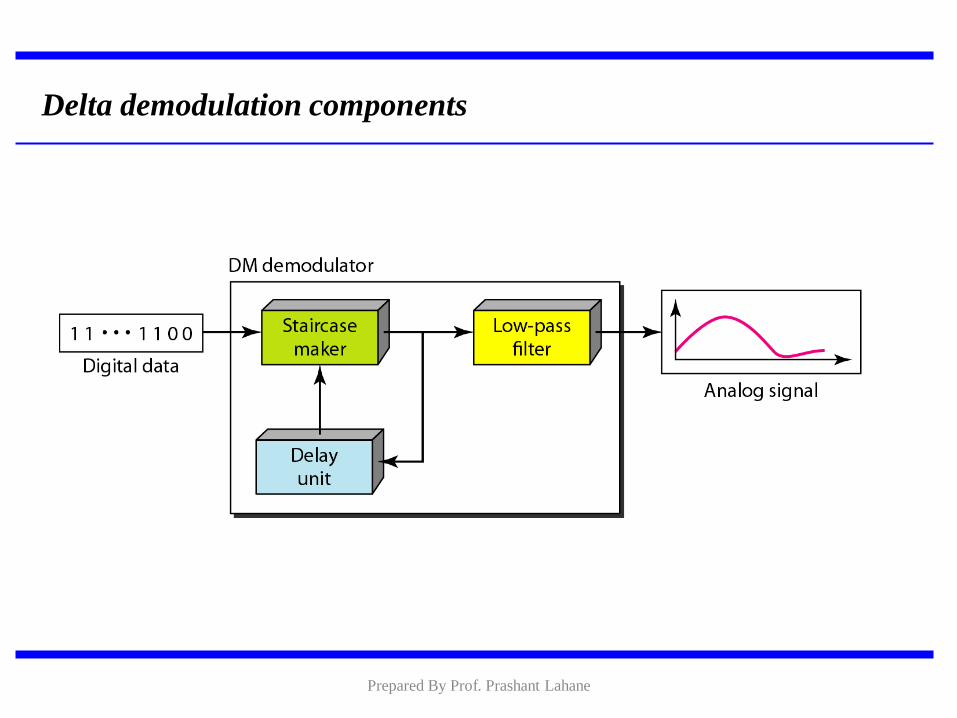
Delta demodulation components
Prepared By Prof. Prashant Lahane
Adaptive Delta Modulation, where the
step size is made to vary with the input
Signal.
Prepared By Prof. Prashant Lahane
Adaptive Delta Modulation, where the
step size is made to vary with the input
Signal.
Prepared By Prof. Prashant Lahane
ADAPTIVE DELTA MODULATION
Line Coding
• Digital output of the PCM coder is converted to an appropriate waveform for transmission over channel line coding or transmission coding
• Different line codes have different attributes
• Best line code has to be selected for a given application and channel condition
Prepared By Prof. Prashant Lahane
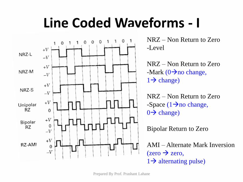
Line Coded Waveforms - I NRZ – Non Return to Zero
-Level
NRZ – Non Return to Zero
-Mark (0no change,
1 change)
NRZ – Non Return to Zero
-Space (1no change,
0 change)
Bipolar Return to Zero
AMI – Alternate Mark Inversion
(zero zero,
1 alternating pulse)
Prepared By Prof. Prashant Lahane
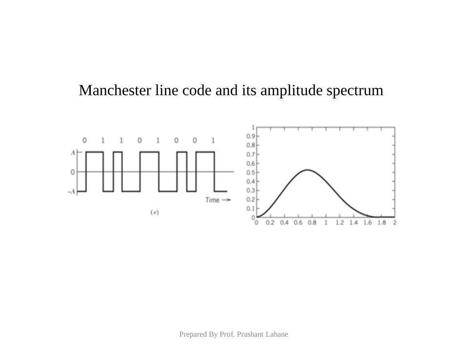
Manchester line code and its amplitude spectrum
Prepared By Prof. Prashant Lahane
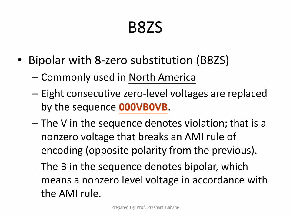
B8ZS
• Bipolar with 8-zero substitution (B8ZS)
– Commonly used in North America
– Eight consecutive zero-level voltages are replaced by the sequence 000VB0VB.
– The V in the sequence denotes violation; that is a nonzero voltage that breaks an AMI rule of encoding (opposite polarity from the previous).
– The B in the sequence denotes bipolar, which means a nonzero level voltage in accordance with the AMI rule.
Prepared By Prof. Prashant Lahane
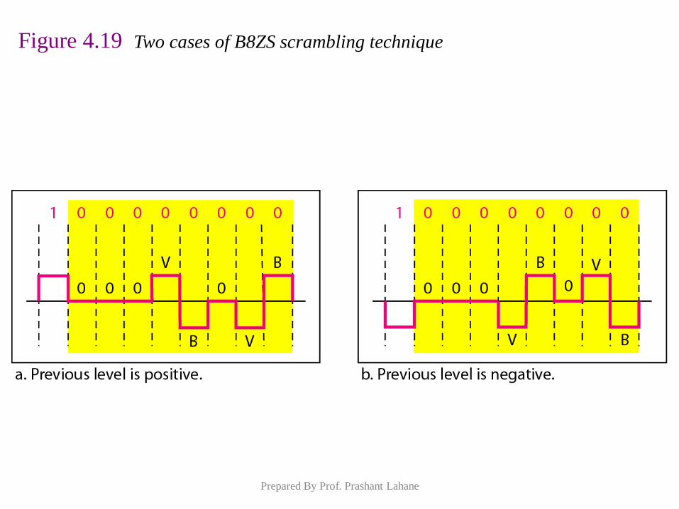
Figure 4.19 Two cases of B8ZS scrambling technique
Prepared By Prof. Prashant Lahane
B8ZS substitutes eight consecutive zeros with 000VB0VB.
Note
Prepared By Prof. Prashant Lahane
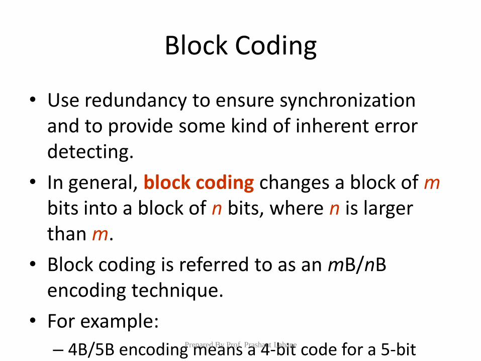
Block Coding
• Use redundancy to ensure synchronization and to provide some kind of inherent error detecting.
• In general, block coding changes a block of m bits into a block of n bits, where n is larger than m.
• Block coding is referred to as an mB/nB encoding technique.
• For example:
– 4B/5B encoding means a 4-bit code for a 5-bit group.
Prepared By Prof. Prashant Lahane
Block coding is normally referred to as mB/nB coding;
it replaces each m-bit group with an
n-bit group.
Note
Prepared By Prof. Prashant Lahane
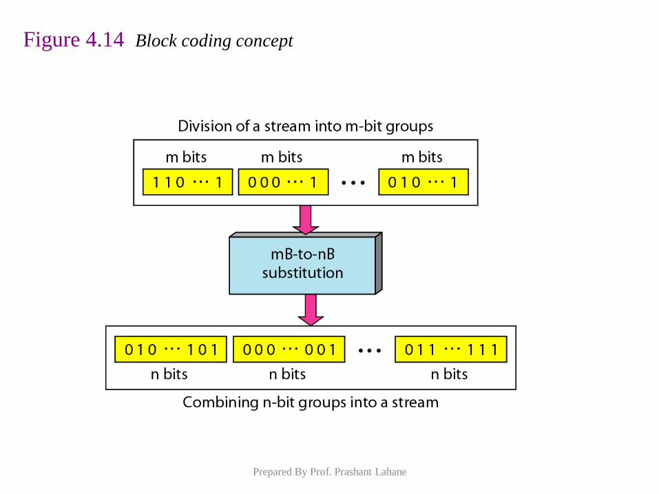
Figure 4.14 Block coding concept
Prepared By Prof. Prashant Lahane
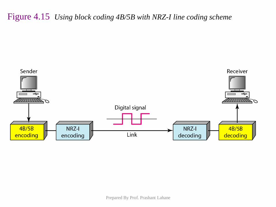
Figure 4.15 Using block coding 4B/5B with NRZ-I line coding scheme
Prepared By Prof. Prashant Lahane
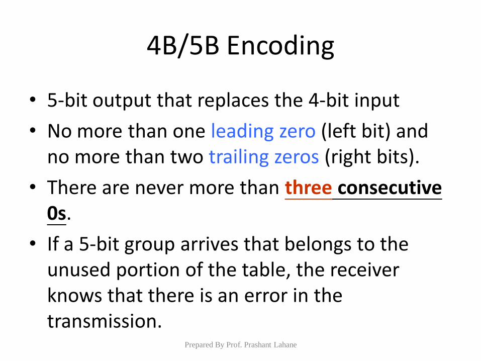
4B/5B Encoding
• 5-bit output that replaces the 4-bit input
• No more than one leading zero (left bit) and no more than two trailing zeros (right bits).
• There are never more than three consecutive 0s.
• If a 5-bit group arrives that belongs to the unused portion of the table, the receiver knows that there is an error in the transmission.
Prepared By Prof. Prashant Lahane
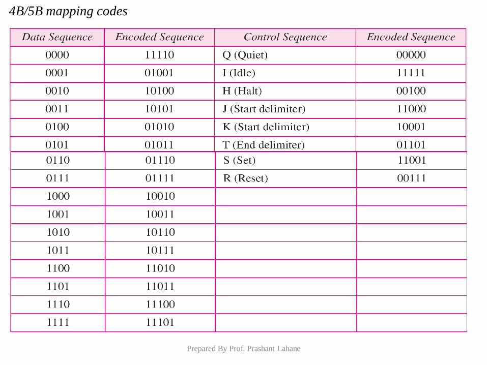
4B/5B mapping codes
Prepared By Prof. Prashant Lahane
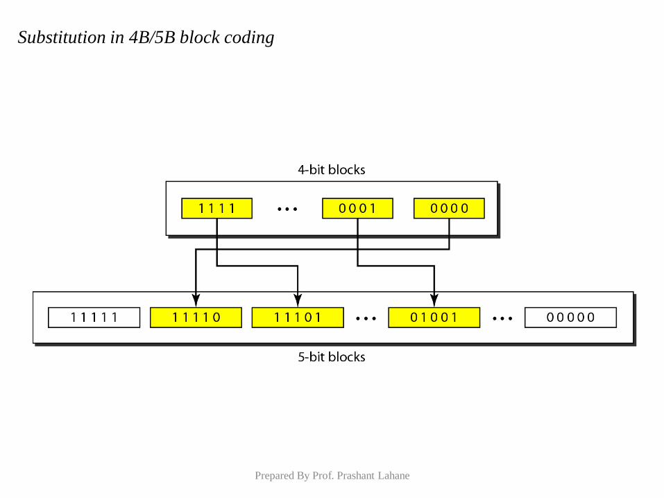
Substitution in 4B/5B block coding
Prepared By Prof. Prashant Lahane
Introduction
The multiplexing is used to combined a number of independent
signals into a composite signal suitable for transmission over a
common channel
Type of Multiplexing
Prepared By Prof. Prashant Lahane
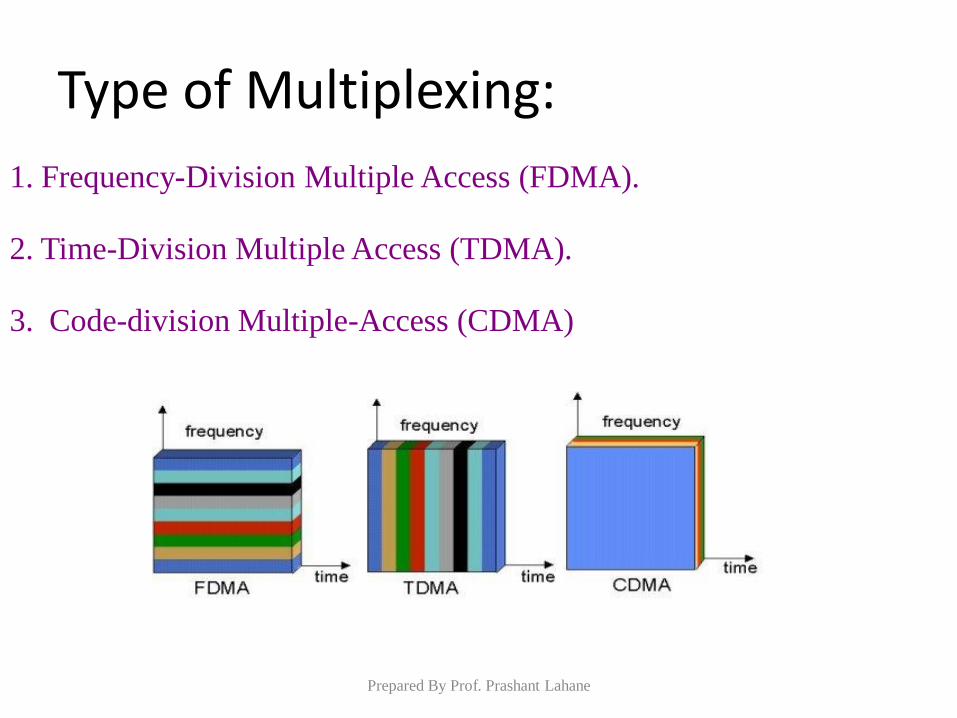
Type of Multiplexing:
1. Frequency-Division Multiple Access (FDMA).
3. Code-division Multiple-Access (CDMA)
2. Time-Division Multiple Access (TDMA).
Prepared By Prof. Prashant Lahane
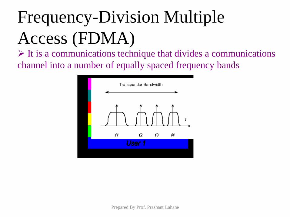
Frequency-Division Multiple
Access (FDMA) It is a communications technique that divides a communications
channel into a number of equally spaced frequency bands
Prepared By Prof. Prashant Lahane
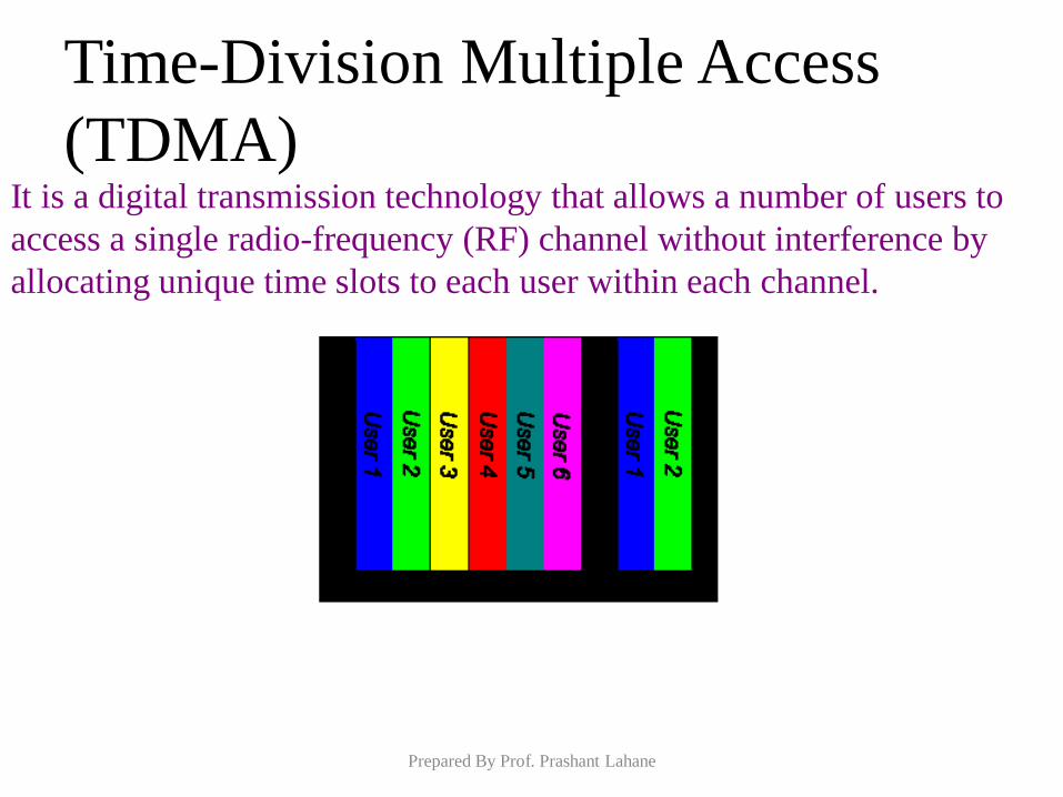
Time-Division Multiple Access
(TDMA) It is a digital transmission technology that allows a number of users to
access a single radio-frequency (RF) channel without interference by
allocating unique time slots to each user within each channel.
Prepared By Prof. Prashant Lahane
Code Division Multiple Access
(CDMA) It is a wireless communications technology that uses the
principle of spread spectrum communication.
There are three ways to spread the bandwidth of the signal:
Frequency hopping
Time hopping
Direct sequence
Prepared By Prof. Prashant Lahane
Code Division Multiple Access
(CDMA)
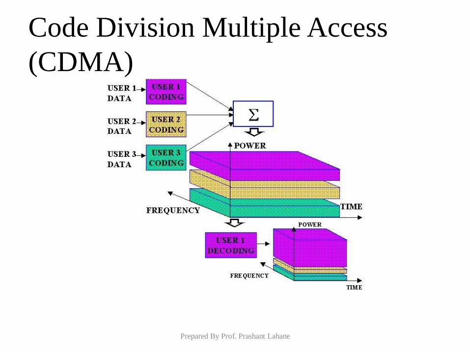
CDMA Features:
o All users use same frequency and may transmit simultaneously
o Narrowband message signal multiplied by wideband spreading signal, or codeword
o Each user has its own pseudo-codeword (orthogonal to others).
o Receivers detect only the desired codeword. All others appear
as noise.
o Receivers must know transmitter’s codeword.
CDMA is a Direct Sequence Spread Spectrum system
Prepared By Prof. Prashant Lahane
Code Division Multiple Access
(CDMA)
Prepared By Prof. Prashant Lahane
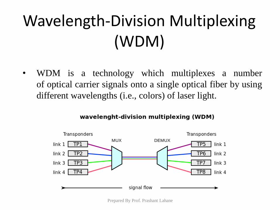
Wavelength-Division Multiplexing (WDM)
Prepared By Prof. Prashant Lahane
• WDM is a technology which multiplexes a number
of optical carrier signals onto a single optical fiber by using
different wavelengths (i.e., colors) of laser light.
WDM
• The term wavelength-division multiplexing is commonly
applied to an optical carrier (which is typically described by
its wavelength), whereas frequency-division
multiplexing typically applies to a radio carrier (which is
more often described by frequency).
• Wavelength and frequency are tied together through a simple
directly inverse relationship, in which the product of frequency
and wavelength equals c (the propagation speed of light), the
two terms actually describe the same concept.
• WDM systems are popular with telecommunications
companies because they allow them to expand the capacity of
the network without laying more fiber. Prepared By Prof. Prashant Lahane
Time Division Synchronous Code Division
Multiple Access (TD-SCDMA)
• TD-SCDMA is the 3G standard developed for and used by China Mobile on the Chinese mainland. When 3G was just beginning in China, ChinaMobile decided to develop their own format of 3G so to avoid paying highly expensive patent fees.
Prepared By Prof. Prashant Lahane
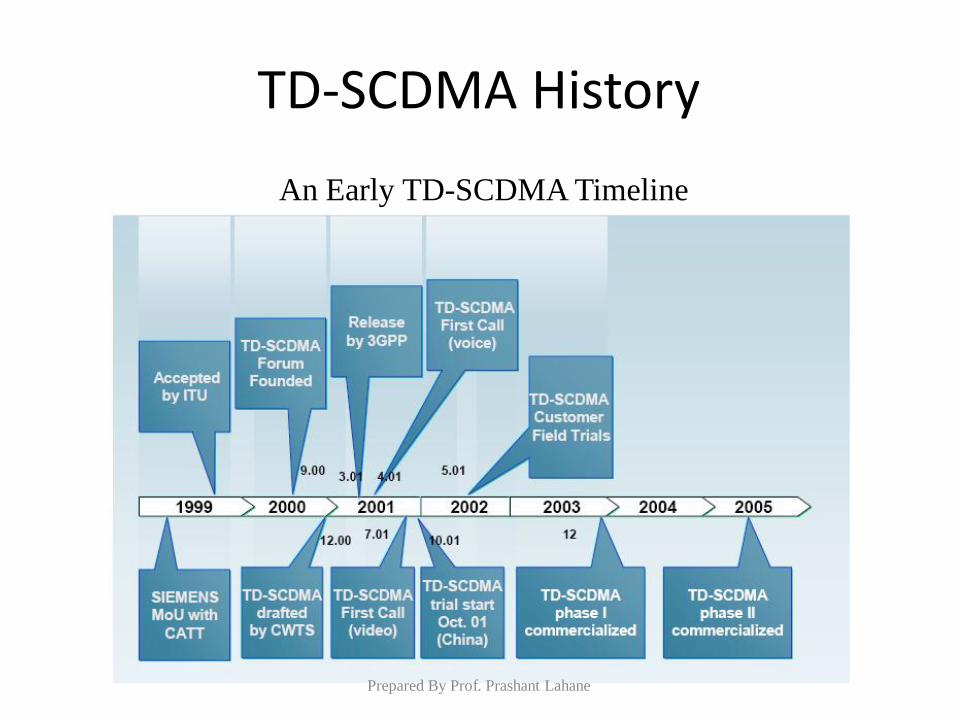
TD-SCDMA History
An Early TD-SCDMA Timeline
Prepared By Prof. Prashant Lahane
TD-SCDMA
Prepared By Prof. Prashant Lahane
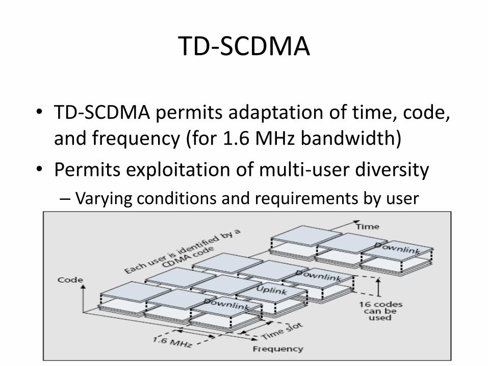
• TD-SCDMA permits adaptation of time, code, and frequency (for 1.6 MHz bandwidth)
• Permits exploitation of multi-user diversity
– Varying conditions and requirements by user
Long Term Evolution (LTE)
• It is a standard for wireless communication of high-
speed data for mobile phones and data terminals (4G
LTE).
• Peak download rates up to 299.6 Mbit/s and upload
rates up to 75.4 Mbit/s
• Low data transfer latencies (5 ms)
• LTE has two variants:
– LTE TDD (Time division duplex)
– LTE FDD (Frequency division duplex)
Prepared By Prof. Prashant Lahane
LTE-TDD & LTE-FDD
• LTE-FDD uses paired frequencies to upload and
download data.
• LTE-TDD uses a single frequency, alternating
between uploading and downloading data through
time.
• The ratio between uploads and downloads on a LTE-
TDD network can be changed dynamically,
depending on whether more data needs to be sent or
received.
Prepared By Prof. Prashant Lahane
LTE-TDD & LTE-FDD
• TD-LTE and LTE FDD operates on different
frequency bands, with LTE-TDD working better at
higher frequencies, and LTE-FDD working better at
lower frequencies.
• Frequencies used for LTE-TDD range from 1850
MHz to 3800 MHz, with several different bands
being used.
• The LTE-TDD spectrum is generally cheaper to
access, and has less traffic
Prepared By Prof. Prashant Lahane
LAN Standards
Prepared By Prof. Prashant Lahane
Ethernet
• Ethernet refers to the family of local area networks (LAN) products covered by the IEEE 802.3 that operates at many speeds.
• It defines a number of wiring for the physical layer, through means of Network access at the Media Access Control (MAC)/Data Link Layer, and a Common addressing format.
Prepared By Prof. Prashant Lahane
Ethernet (cont)
• The combination of the twisted pair versions of Ethernet with the fiber optic versions largely replacing standards such as coaxial cable Ethernet.
• In recent years, Wi-Fi, the wireless LAN standardized by IEEE 802.11, has been used instead of Ethernet for many home and small office networks and in addition to Ethernet in larger installations.
Prepared By Prof. Prashant Lahane
History
• The original Ethernet was developed as an experimental coaxial cable Network to operate with a data rate of 3 Mbps using (CSMA/CD) Protocol.
• Success with that project attracted early attention and specification and led to the 1980 joint development of the 10-Mbps Ethernet Version 1.0.
Prepared By Prof. Prashant Lahane
History (cont)
• The draft standard was approved by the 802.3 working group in 1983 and published as an official standard in 1985.
• Since then, a number of supplements to the standard have been defined to take advantage of improvements in the technologies and to support:
1) additional network media
2) higher data rate capabilities
Prepared By Prof. Prashant Lahane
General Description
• Ethernet was originally based on the idea of computers communicating over a shared coaxial cable acting as a broadcast transmission medium.
• The common cable providing the communication channel was likened to the ether and it was from this reference that the name "Ethernet" was derived.
Prepared By Prof. Prashant Lahane
General Description (cont)
• Three data rates are currently defined for operation over optical fiber and twisted-pair cables:
• 10 Mbps—10Base-T Ethernet
• 100 Mbps—Fast Ethernet
• 1000 Mbps—Gigabit Ethernet
Prepared By Prof. Prashant Lahane

Ethernet Network Elements
• Ethernet LANs consist of network nodes and interconnecting media.
• The network nodes fall into two major classes:
1) Data terminal equipment (DTE).
2) Data communication equipment (DCE).
• The current Ethernet media options include two types of copper cable: (UTP) and (STP), plus several types of optical fiber cable.
Prepared By Prof. Prashant Lahane
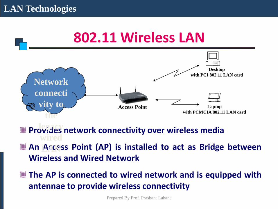
802.11 Wireless LAN
Provides network connectivity over wireless media
An Access Point (AP) is installed to act as Bridge between Wireless and Wired Network
The AP is connected to wired network and is equipped with antennae to provide wireless connectivity
LAN Technologies
Network
connecti
vity to
the
legacy
wired
LAN
Desktop
with PCI 802.11 LAN card
Laptop
with PCMCIA 802.11 LAN card Access Point
Prepared By Prof. Prashant Lahane
802.11 Wireless LAN Range ( Distance between Access Point and WLAN client) depends on structural hindrances and RF gain of the antenna at the Access Point
To service larger areas, multiple APs may be installed with a 20-30% overlap
A client is always associated with one AP and when the client moves closer to another AP, it associates with the new AP (Hand-Off)
Three flavors:
802.11b
802.11a
802.11g
LAN Technologies
Prepared By Prof. Prashant Lahane
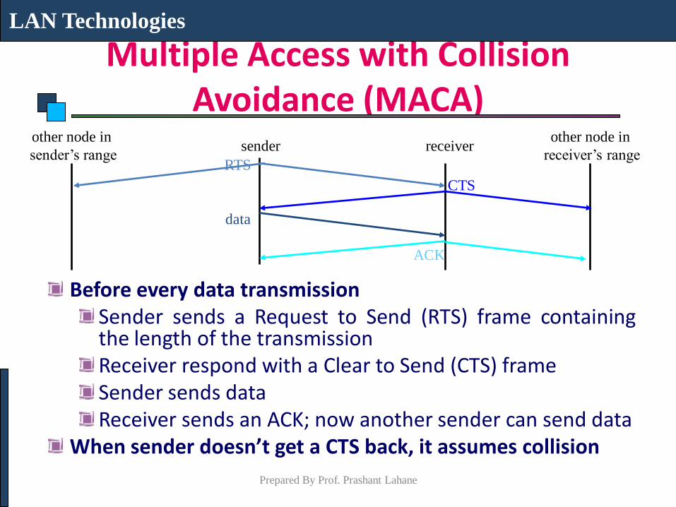
Multiple Access with Collision Avoidance (MACA)
Before every data transmission Sender sends a Request to Send (RTS) frame containing the length of the transmission Receiver respond with a Clear to Send (CTS) frame Sender sends data Receiver sends an ACK; now another sender can send data
When sender doesn’t get a CTS back, it assumes collision
LAN Technologies
sender receiver other node in
sender’s range RTS
CTS
ACK
data
other node in
receiver’s range
Prepared By Prof. Prashant Lahane
WLAN : 802.11b The most popular 802.11 standard currently in deployment.
Supports 1, 2, 5.5 and 11 Mbps data rates in the 2.4 GHz ISM (Industrial-Scientific-Medical) band
LAN Technologies
Prepared By Prof. Prashant Lahane
WLAN : 802.11a Operates in the 5 GHz UNII (Unlicensed National Information Infrastructure) band
Incompatible with devices operating in 2.4GHz
Supports Data rates up to 54 Mbps.
LAN Technologies
Prepared By Prof. Prashant Lahane
WLAN : 802.11g Supports data rates as high as 54 Mbps on the 2.4 GHz band
Provides backward compatibility with 802.11b equipment
LAN Technologies
Prepared By Prof. Prashant Lahane
Prepared By Prof. Prashant Lahane
WiMAX: Broadband Wireless Access
Prepared By Prof. Prashant
Lahane
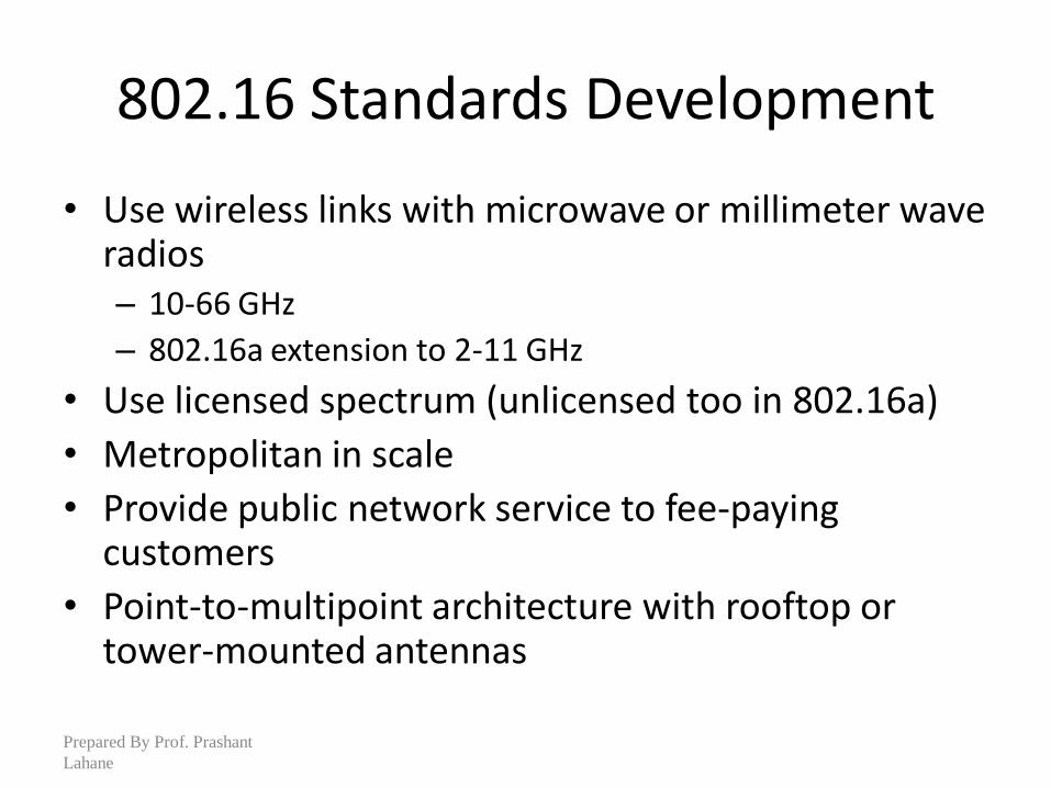
802.16 Standards Development
• Use wireless links with microwave or millimeter wave radios – 10-66 GHz
– 802.16a extension to 2-11 GHz
• Use licensed spectrum (unlicensed too in 802.16a)
• Metropolitan in scale
• Provide public network service to fee-paying customers
• Point-to-multipoint architecture with rooftop or tower-mounted antennas
Prepared By Prof. Prashant
Lahane
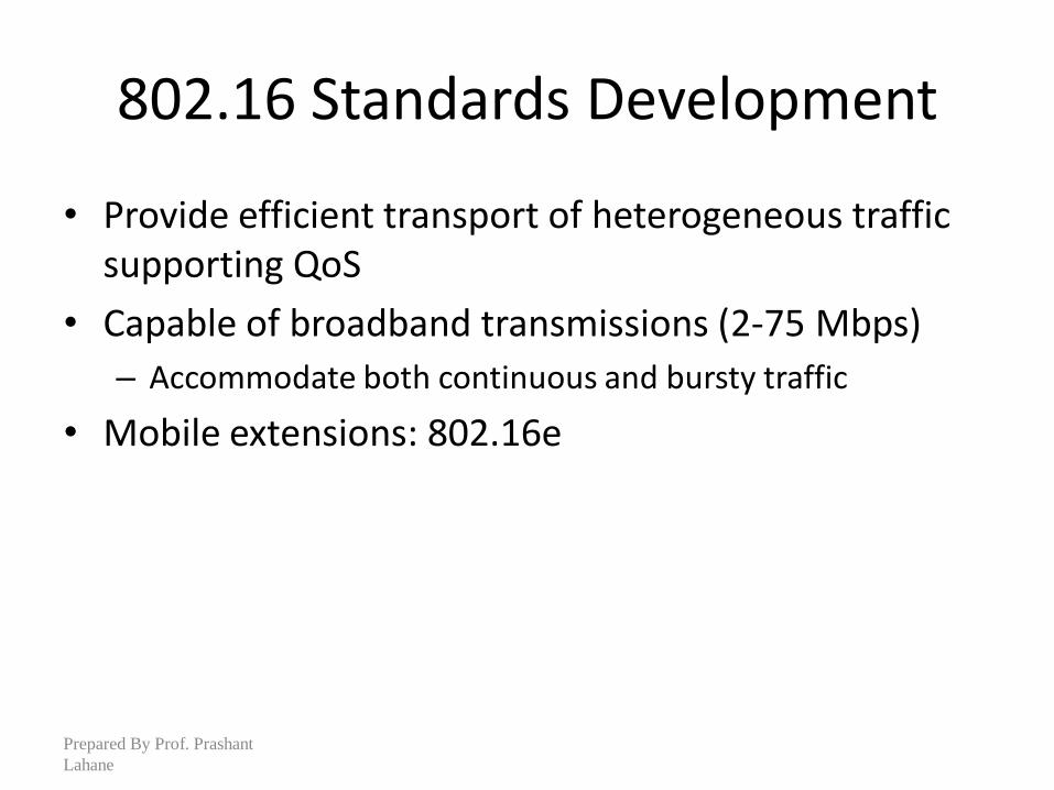
802.16 Standards Development
• Provide efficient transport of heterogeneous traffic supporting QoS
• Capable of broadband transmissions (2-75 Mbps)
– Accommodate both continuous and bursty traffic
• Mobile extensions: 802.16e
Prepared By Prof. Prashant
Lahane
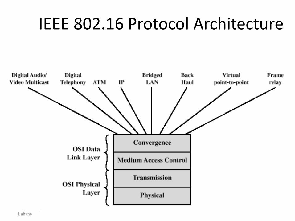
IEEE 802.16 Protocol Architecture
Prepared By Prof. Prashant
Lahane
Protocol Architecture
• Physical layer functions: – Encoding/decoding of signals
– Preamble generation/removal
– Bit transmission/reception
• Medium access control layer functions: – On transmission, assemble data into a frame with address
and error detection fields
– On reception, disassemble frame, and perform address recognition and error detection
– Govern access to the wireless transmission medium
Prepared By Prof. Prashant
Lahane
Protocol Architecture
• Convergence layer functions: – Encapsulate PDU framing of upper layers into
native 802.16 MAC/PHY frames
– Map upper layer’s addresses into 802.16 addresses
– Translate upper layer QoS parameters into native 802.16 MAC format
– Adapt time dependencies of upper layer traffic into equivalent MAC service
Prepared By Prof. Prashant
Lahane
IEEE 802.16 Services
• Digital audio/video multicast
• Digital telephony
• ATM
• Internet protocol
• Bridged LAN
• Back-haul
• Frame relay
Zigbee
Prepared By Prof. Prashant Lahane
What is ZigBee?
• Technological Standard Created for Control and Sensor Networks
• Based on the IEEE 802.15.4 Standard
• Created by the ZigBee Alliance
Prepared By Prof. Prashant Lahane
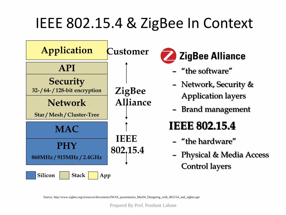
– “the software”
– Network, Security &
Application layers
– Brand management
IEEE 802.15.4
– “the hardware”
– Physical & Media Access
Control layers
IEEE 802.15.4 & ZigBee In Context
PHY 868MHz / 915MHz / 2.4GHz
MAC
Network Star / Mesh / Cluster-Tree
Security 32- / 64- / 128-bit encryption
Application
API
ZigBee Alliance
IEEE 802.15.4
Customer
Silicon Stack App
Source: http://www.zigbee.org/resources/documents/IWAS_presentation_Mar04_Designing_with_802154_and_zigbee.ppt
Prepared By Prof. Prashant Lahane
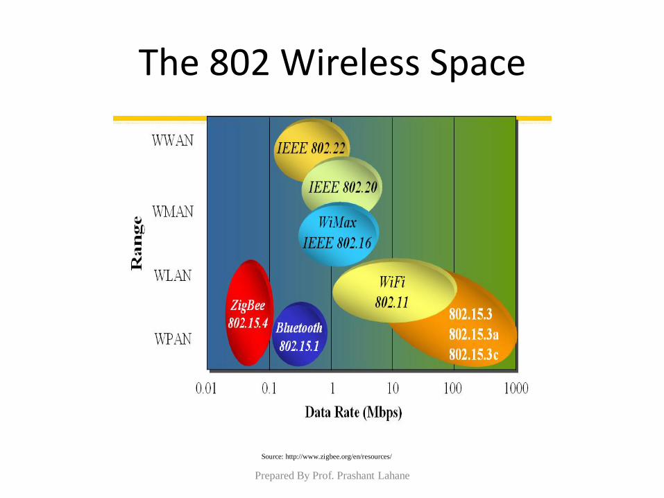
The 802 Wireless Space
Source: http://www.zigbee.org/en/resources/
Prepared By Prof. Prashant Lahane
ZigBee Aims Low
• Low data rate
• Low power consumption
• Small packet devices
Prepared By Prof. Prashant Lahane
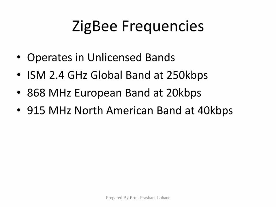
ZigBee Frequencies
• Operates in Unlicensed Bands
• ISM 2.4 GHz Global Band at 250kbps
• 868 MHz European Band at 20kbps
• 915 MHz North American Band at 40kbps
Prepared By Prof. Prashant Lahane
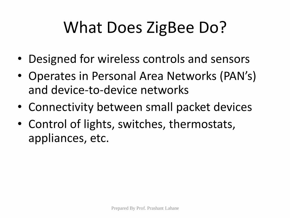
What Does ZigBee Do?
• Designed for wireless controls and sensors
• Operates in Personal Area Networks (PAN’s) and device-to-device networks
• Connectivity between small packet devices
• Control of lights, switches, thermostats, appliances, etc.
Prepared By Prof. Prashant Lahane
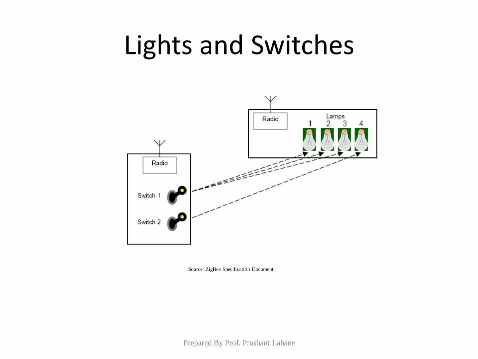
Lights and Switches
Source: ZigBee Specification Document
Prepared By Prof. Prashant Lahane
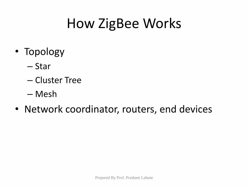
How ZigBee Works
• Topology
– Star
– Cluster Tree
– Mesh
• Network coordinator, routers, end devices
Prepared By Prof. Prashant Lahane
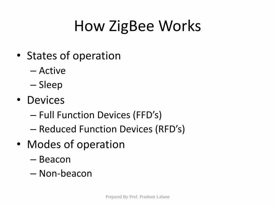
How ZigBee Works
• States of operation – Active
– Sleep
• Devices – Full Function Devices (FFD’s)
– Reduced Function Devices (RFD’s)
• Modes of operation – Beacon
– Non-beacon
Prepared By Prof. Prashant Lahane
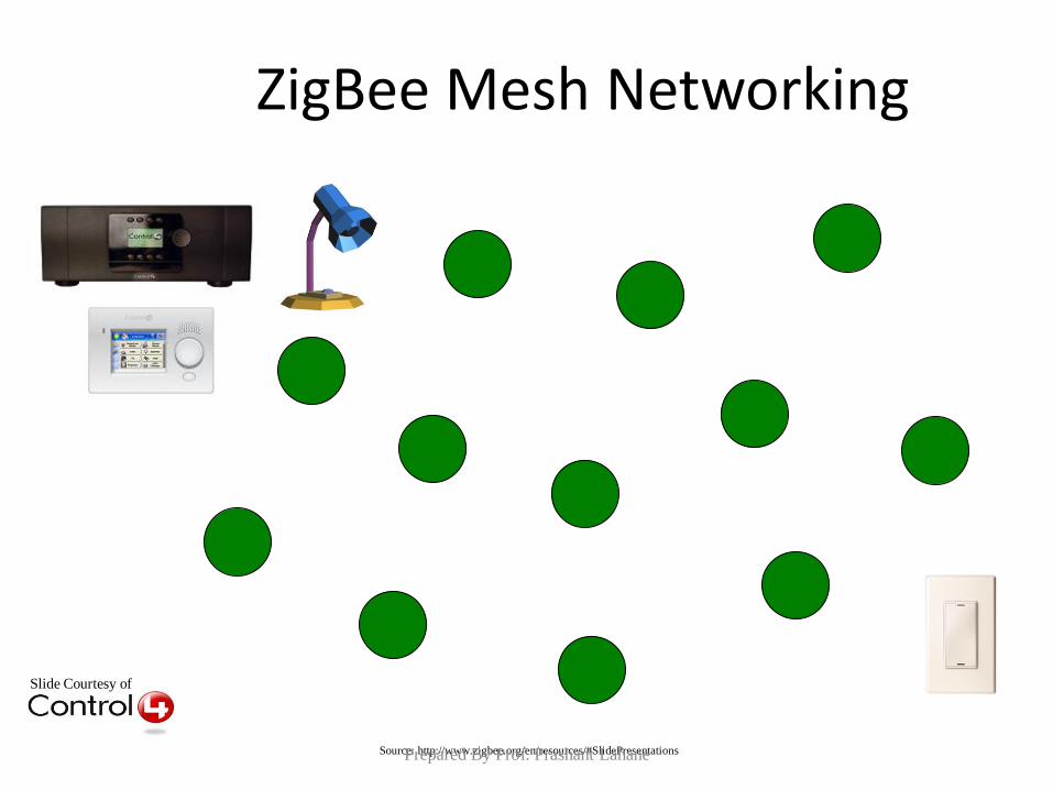
Slide Courtesy of
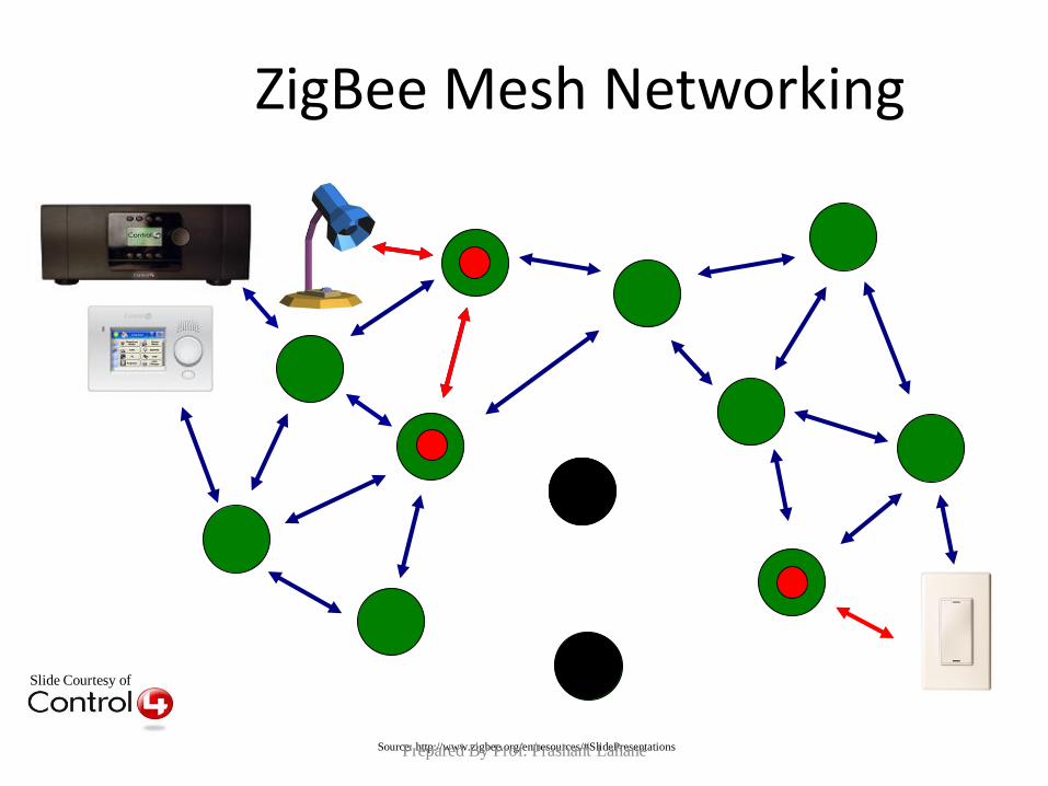
ZigBee Mesh Networking
Source: http://www.zigbee.org/en/resources/#SlidePresentations Prepared By Prof. Prashant Lahane
Slide Courtesy of
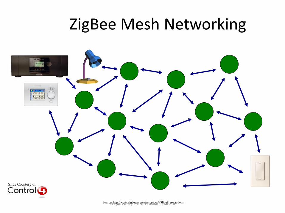
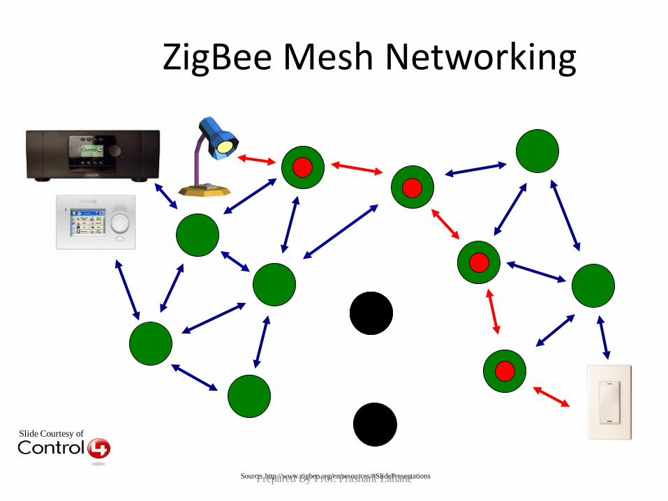
ZigBee Mesh Networking
Source: http://www.zigbee.org/en/resources/#SlidePresentations Prepared By Prof. Prashant Lahane
Slide Courtesy of
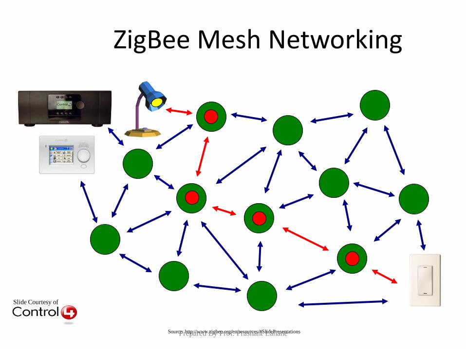
ZigBee Mesh Networking
Source: http://www.zigbee.org/en/resources/#SlidePresentations Prepared By Prof. Prashant Lahane
Slide Courtesy of
ZigBee Mesh Networking
Source: http://www.zigbee.org/en/resources/#SlidePresentations Prepared By Prof. Prashant Lahane
Slide Courtesy of
ZigBee Mesh Networking
Source: http://www.zigbee.org/en/resources/#SlidePresentations Prepared By Prof. Prashant Lahane
Bluetooth
• Bluetooth is a standard developed by a group of electronics manufacturers that will allow any sort of electronic equipment -- from computers and cell phones to keyboards and headphones -- to make its own connections, without wires, cables or any direct action from a user.
• A key difference with other existing wireless technologies is that bluetooth enables combined usability models based on functions provided by different devices.
Prepared By Prof. Prashant Lahane
• The Bluetooth Special Interest Group comprises more than 1000 companies.The major companies who created the technology include Intel
3 com
Ericcson
IBM
Motorola
Nokia
Toshiba
Prepared By Prof. Prashant Lahane
The Name –Bluetooth?
• The name is attributed to Harald Bluetooth was
king of Denmark around the turn of the last
millennium.
• Choosing this name for the standard indicates
how important companies from the Baltic region
(nations including Denmark, Sweden, Norway
and Finland) are to the communications industry
Prepared By Prof. Prashant Lahane
• Present wireless technology like infra red data communication has two problems –1)Line of Sight 2) One to One
• Using data synchronizing– e.g. hot syn on a PDA --- problem of using the right cradle and cable.
• BLUETOOTH OVERCOMES THESE PROBLEMS
Prepared By Prof. Prashant Lahane
• It provides agreement at the physical level -- Bluetooth is a radio-frequency standard.
• Provides agreement at the data link level where products have to agree on
when bits are sent
how many will be sent at a time
how the parties in a conversation can be sure that the message received is the same as the message sent
Prepared By Prof. Prashant Lahane
The Basic Idea
• Bluetooth is a standard for a small , cheap radio chip to be plugged into computers, printers, mobile phones, etc
• Bluetooth chip is designed to replace cables.Information normally carried by the cable, is transmitted at a special frequency to a receiver Bluetooth chip.
• These devices can form a quick ad-hoc secure “piconet” and start communication.
• Connections in the “piconets” can occur even when mobile.
Prepared By Prof. Prashant Lahane
“Piconet”
– A collection of devices connected via Bluetooth technology in an ad hoc fashion.
– A piconet starts with two connected devices, and may grow to eight connected devices.
– All Bluetooth devices are peer units and have identical implementations. However, when establishing a piconet, one unit will act as a Master and the other(s) as slave(s) for the duration of the piconet connection.
Prepared By Prof. Prashant Lahane
Requirements
• Low cost as cables – chip $5
• Secure as cables – must support authentication and encryption
• Must support both data and voice.
• Must connect to a variety of devices.
• Must be able to function in a noisy environment.
• Data rates – 721kbps , using the 2.45Ghz radio frequency band –I.S.M (Industrial, scientific and medical)
• Must support many simultaneous and private “piconets”.
• Must be low power, compact and global.
Prepared By Prof. Prashant Lahane

Prepared By Prof. Prashant Lahane
Satellite Networks
Prepared By Prof. Prashant Lahane
Why Satellite Networks ?
• Wide geographical area coverage
• From kbps to Gbps communication everywhere
• Faster deployment than terrestrial infrastructures
• Bypass clogged terrestrial networks and are oblivious to terrestrial disasters
• Supporting both symmetrical and asymmetrical architectures
• Seamless integration capability with terrestrial networks
• Very flexible bandwidth-on-demand capabilities
• Flexible in terms of network configuration and capacity allocation
• Broadcast, Point-to-Point and Multicast capabilities
• Scalable
Prepared By Prof. Prashant Lahane
Orbits
• Defining the altitude where the satellite will
operate.
• Determining the right orbit depends on proposed
service characteristics such as coverage,
applications, delay.
Prepared By Prof. Prashant Lahane
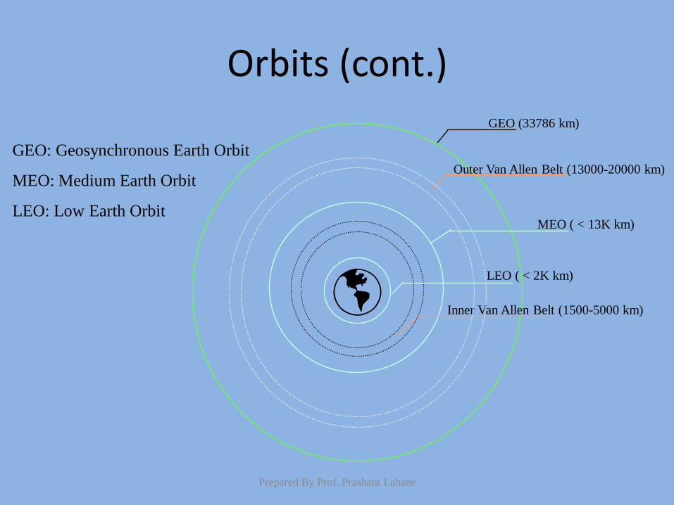
Orbits (cont.)
Outer Van Allen Belt (13000-20000 km)
MEO ( < 13K km)
GEO (33786 km)
LEO ( < 2K km)
Inner Van Allen Belt (1500-5000 km)
GEO: Geosynchronous Earth Orbit
MEO: Medium Earth Orbit
LEO: Low Earth Orbit
Prepared By Prof. Prashant Lahane
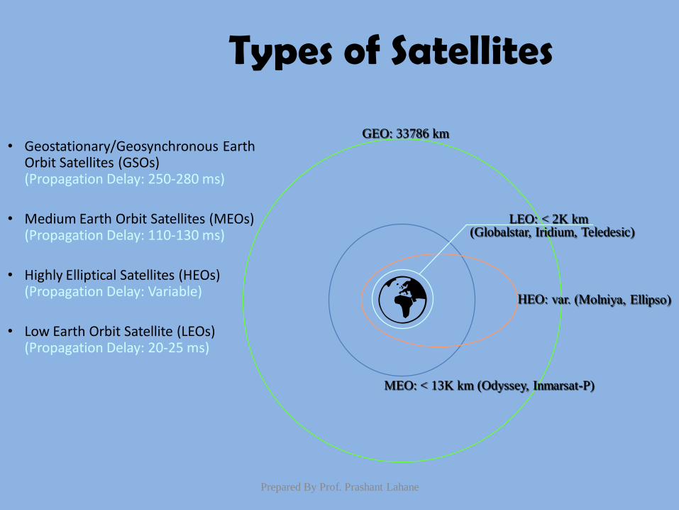
Types of Satellites
LEO: < 2K km
MEO: < 13K km (Odyssey, Inmarsat-P)
GEO: 33786 km
(Globalstar, Iridium, Teledesic)
• Geostationary/Geosynchronous Earth Orbit Satellites (GSOs) (Propagation Delay: 250-280 ms)
• Medium Earth Orbit Satellites (MEOs) (Propagation Delay: 110-130 ms)
• Highly Elliptical Satellites (HEOs) (Propagation Delay: Variable)
• Low Earth Orbit Satellite (LEOs) (Propagation Delay: 20-25 ms)
Prepared By Prof. Prashant Lahane
Geostationary/Geosynchronous Earth Orbit
Satellites (GSOs)
• 33786 km equatorial orbit
• Rotation speed equals Earth rotation speed (Satellite seems fixed in the horizon)
• Wide coverage area
• Applications (Broadcast/Fixed Satellites, Direct
Broadcast, Mobile Services)
Prepared By Prof. Prashant Lahane
Advantages of GSOs
• Wide coverage
• High quality and Wideband communications
• Economic Efficiency
• Tracking process is easier because of its
synchronization to Earth
Prepared By Prof. Prashant Lahane
Disadvantages of GSOs
• Long propagation delays (250-280 ms). (e.g., Typical Intern. Tel. Call 540 ms round-trip delay.
Echo cancelers needed. Expensive!)
(e.g., Delay may cause errors in data;
Error correction /detection techniques are needed.)
• Large propagation loss. Requirement for high
power level. (e.g., Future hand-held mobile terminals have limited power supply.)
Currently: smallest terminal for a GSO is as large as an A4 paper and as
heavy as 2.5 Kg.
Prepared By Prof. Prashant Lahane
Disadvantages of GSOs (cont.)
• Lack of coverage at Northern and Southern latitudes.
• High cost of launching a satellite.
• Enough spacing between the satellites to avoid collisions.
• Existence of hundreds of GSOs belonging to different countries.
• Available frequency spectrum assigned to GSOs is limited.
Prepared By Prof. Prashant Lahane
Medium Earth Orbit Satellites (MEOs)
• Positioned in 10-13K km range.
• Delay is 110-130 ms.
• Will orbit the Earth at less than 1 km/s.
• Applications
– Mobile Services/Voice (Intermediate Circular Orbit
(ICO) Project)
– Fixed Multimedia (Expressway)
Prepared By Prof. Prashant Lahane
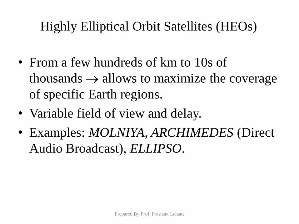
Highly Elliptical Orbit Satellites (HEOs)
• From a few hundreds of km to 10s of
thousands allows to maximize the coverage
of specific Earth regions.
• Variable field of view and delay.
• Examples: MOLNIYA, ARCHIMEDES (Direct
Audio Broadcast), ELLIPSO.
Prepared By Prof. Prashant Lahane
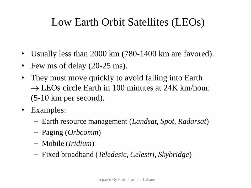
Low Earth Orbit Satellites (LEOs)
• Usually less than 2000 km (780-1400 km are favored).
• Few ms of delay (20-25 ms).
• They must move quickly to avoid falling into Earth
LEOs circle Earth in 100 minutes at 24K km/hour.
(5-10 km per second).
• Examples:
– Earth resource management (Landsat, Spot, Radarsat)
– Paging (Orbcomm)
– Mobile (Iridium)
– Fixed broadband (Teledesic, Celestri, Skybridge)
Prepared By Prof. Prashant Lahane
Low Earth Orbit Satellites (LEOs) (cont.)
• Little LEOs: 800 MHz range
• Big LEOs: > 2 GHz
• Mega LEOs: 20-30 GHz
Prepared By Prof. Prashant Lahane
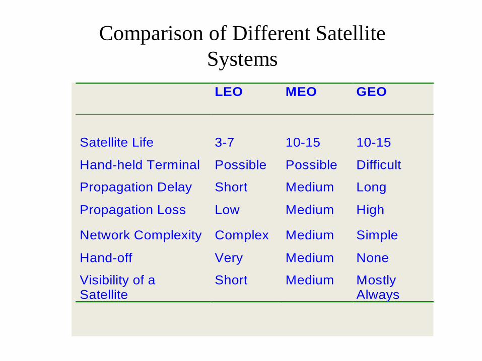
Comparison of Different Satellite
Systems
LEO MEO GEO
Satellite Life 3-7 10-15 10-15
Hand-held Terminal Possible Possible Difficult
Propagation Delay Short Medium Long
Propagation Loss Low Medium High
Network Complexity Complex Medium Simple
Hand-off Very Medium None
Visibility of a Satellite
Short Medium Mostly Always
Cellular Network
Prepared By Prof. Prashant Lahane
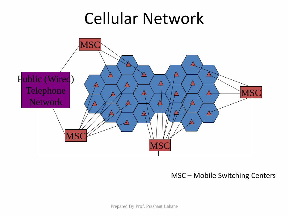
Cellular Network
MSC MSC
MSC
MSC
Public (Wired)
Telephone
Network
MSC – Mobile Switching Centers
Prepared By Prof. Prashant Lahane
Cellular Identifiers
• In AMPS, a cell phone subscription is identified using three numbers:
– Electronic Serial Number (ESN): unique 32 bit number programmed into the cell when it was manufactured.
– Mobile Identification Number (MIN): 10 digit phone number.
– System Identification Code (SID): Unique 5 bit code assigned by the FCC to each service provider.
Prepared By Prof. Prashant Lahane
What happens when you receive a call?
• When you first power the phone, it listens for an SID on the control channel.
• Recall: control channel is special frequency that the phone and base station use to talk to each other about things like call setup and channel changing, etc.
• If phone cannot find any control channels, then it is out of range and it lights up the “No Service” light.
Prepared By Prof. Prashant Lahane
Call Reception
• When it receives in SID, the phone compares it to the SID programmed in the phone.
– If it matches, then phone is in the home system.
– If it does not match, the phone is roaming.
• Phone transmits a registration request to the base, which
forward this request to the MSC.
Prepared By Prof. Prashant Lahane
Location Registry
• MSC uses this registration request to update a large database (called the location registry) which keeps track of the latest location of the cell phone.
• This helps network find a phone when a call comes in for it.
• Also it informs the MSC if the cell phone user is valid (legitimate paying customer).
• MSC also learns of phone subscription features, like caller-id, etc., from the MSC.
Prepared By Prof. Prashant Lahane
Call Reception
• Assume a call comes in for the phone.
• The MSC tries to find the phone by looking up the database.
• MSC uses a frequency in the cell in which the phone was last in, and transmits an “incoming call” message over the control channel with the phone’s ESN and MIN numbers.
• This message also tells the phone which frequency to switch to communicate with the base and complete the conversation.
Prepared By Prof. Prashant Lahane
Call Reception; Call Handoff
• The phone and base station tower switch to these frequencies and the call is connected.
• Now assume the phone user is moving around and moves to the edge of its serving cell.
• Base station notes that the strength of the radio waves from this phone is diminishing.
• Meanwhile, a nearby base station notes that the signal strength to this phone is increasing.
Prepared By Prof. Prashant Lahane
Call Handoff
• All base stations constant monitor the signal strength on all voice channels (all 416) in order to pinpoint users who may be moving into their coverage area.
• When the signal gets weak enough at the first base station and strong enough at the second base station, the base stations send a signal to the MSC.
• The MSC determines the new frequency in the new cell that user should switch to.
Prepared By Prof. Prashant Lahane
Call Handoff (Cont’d)
• The new frequency is conveyed to the phone.
• The phone switches to the new frequency (seamlessly) and the new base station tunes into this frequency and starts receiving signals from the phone.
• This way the phone gets handed-over to the new base station.
Prepared By Prof. Prashant Lahane
Roaming
• When SID of the phone does not match the SID of the nearest base station, the phone knows its roaming.
• The MSC of the system that the phone is roaming in contacts the MSC of the phone’s home system.
• The home MSC verifies the phone (valid, paying user, etc.) to the local MSC. The local MSC then keeps track of the phone as it moves thru the local system. Each time updating the database at the home system.
Prepared By Prof. Prashant Lahane
Cell to Cell Call
• Let’s say there is a phone in a cell that wishes to talk to another phone in that cell.
• Assume that both the phones are in a cell of their home system (thereby, they both have the same home system).
• These two phones must talk to each other via the base station.
• Future cell phones systems (perhaps 4G) may allow phones to connect directly with each other (peer-to-peer connection).
Prepared By Prof. Prashant Lahane
Cell to Cell Call (Cont’d)
• Now assume the two phones are in the same cell, but current cell is part of home system for only one of the phones.
• Assume current cell is in Susquehanna County.
• The other cell phone user is visiting from Florida, where its home system is.
• Assume that the phone from Florida makes a phone call to the Susquehanna phone.
Prepared By Prof. Prashant Lahane
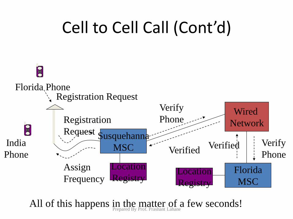
Cell to Cell Call (Cont’d)
India
Phone
Florida Phone
Susquehanna
MSC
Wired
Network
Florida
MSC
Registration
Request
Verify
Phone
Verify
Phone Verified
Verified
Assign
Frequency
Registration Request
All of this happens in the matter of a few seconds!
Location
Registry Location
Registry
Prepared By Prof. Prashant Lahane
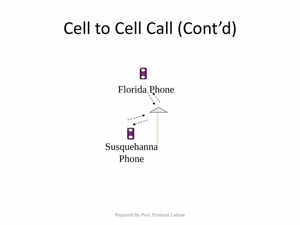
Cell to Cell Call (Cont’d)
Susquehanna
Phone
Florida Phone
Prepared By Prof. Prashant Lahane
Adhoc network
Prepared By Prof. Prashant Lahane
Advent of Ad hoc Wireless Networks
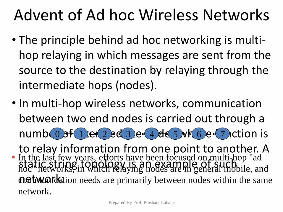
• The principle behind ad hoc networking is multi-hop relaying in which messages are sent from the source to the destination by relaying through the intermediate hops (nodes).
• In multi-hop wireless networks, communication between two end nodes is carried out through a number of intermediate nodes whose function is to relay information from one point to another. A static string topology is an example of such network:
0 1 2 3 4 5 6 7
In the last few years, efforts have been focused on multi-hop "ad
hoc" networks, in which relaying nodes are in general mobile, and
communication needs are primarily between nodes within the same
network. Prepared By Prof. Prashant Lahane
Advent of Ad hoc Wireless Networks
An examples of such developments is the Bluetooth standard that
is one of the first commercial realizations of ad hoc wireless
networking developed by Bluetooth Special Interest Group (SIG):
• A piconet formed by a group of nodes establishes a single-hop (master node)
point-to-point wireless link.
• A scatternet formed by multiple piconets (master nodes) can establish a
multi-hop wireless network.
Though the IEEE 802.11 protocols have developed for the wireless
networks, they don’t function well in multi-hop networks.
Realizing the necessity of open standards in this emerging area of
computer communication, the mobile ad hoc networks (MANET)
standards are being developed by the Internet Working Tasking
Force (IETF) MANET working group.
Prepared By Prof. Prashant Lahane
Advent of Ad hoc Wireless Networks
Even though ad hoc wireless networks are expected to work in the
absence of any fixed infrastructure, recent advances in wireless
network architectures enable the mobile ad hoc nodes to function
in the presence of infrastructure
Multi-hop cellular networks (MCNs), self-organizing packet radio
ad hoc networks with overlay (SOPRANO), and mesh networks
are examples of such types of networks.
Mesh networks serve as access networks that employ multi-hop
wireless forwarding by non-mobile nodes to relay traffic to and
from the wired Internet. In such an environment, hybrid
technologies and/or hierarchical network organization can be used
for ad hoc and infrastructure wireless links.
Prepared By Prof. Prashant Lahane
Cellular and Ad Hoc Wireless Networks
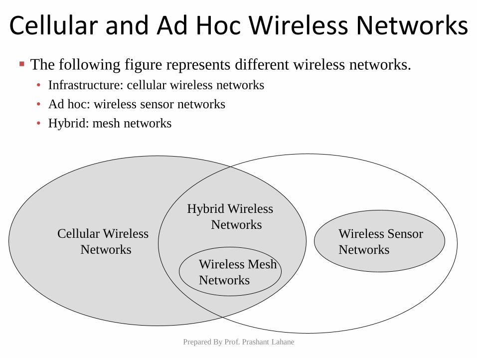
The following figure represents different wireless networks.
• Infrastructure: cellular wireless networks
• Ad hoc: wireless sensor networks
• Hybrid: mesh networks
Cellular Wireless
Networks
Hybrid Wireless
Networks
Wireless Mesh
Networks
Wireless Sensor
Networks
Prepared By Prof. Prashant Lahane
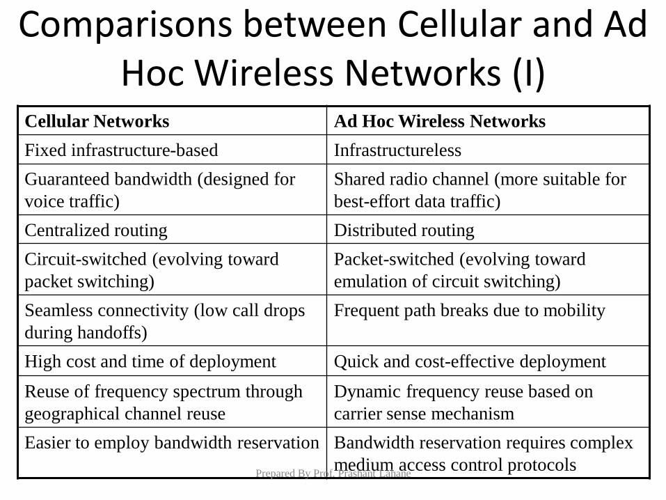
Comparisons between Cellular and Ad Hoc Wireless Networks (I)
Cellular Networks Ad Hoc Wireless Networks
Fixed infrastructure-based Infrastructureless
Guaranteed bandwidth (designed for
voice traffic)
Shared radio channel (more suitable for
best-effort data traffic)
Centralized routing Distributed routing
Circuit-switched (evolving toward
packet switching)
Packet-switched (evolving toward
emulation of circuit switching)
Seamless connectivity (low call drops
during handoffs)
Frequent path breaks due to mobility
High cost and time of deployment Quick and cost-effective deployment
Reuse of frequency spectrum through
geographical channel reuse
Dynamic frequency reuse based on
carrier sense mechanism
Easier to employ bandwidth reservation Bandwidth reservation requires complex
medium access control protocols Prepared By Prof. Prashant Lahane
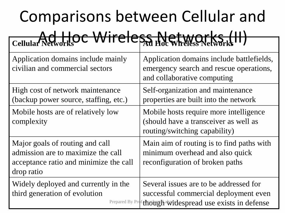
Comparisons between Cellular and Ad Hoc Wireless Networks (II)
Cellular Networks Ad Hoc Wireless Networks
Application domains include mainly
civilian and commercial sectors
Application domains include battlefields,
emergency search and rescue operations,
and collaborative computing
High cost of network maintenance
(backup power source, staffing, etc.)
Self-organization and maintenance
properties are built into the network
Mobile hosts are of relatively low
complexity
Mobile hosts require more intelligence
(should have a transceiver as well as
routing/switching capability)
Major goals of routing and call
admission are to maximize the call
acceptance ratio and minimize the call
drop ratio
Main aim of routing is to find paths with
minimum overhead and also quick
reconfiguration of broken paths
Widely deployed and currently in the
third generation of evolution
Several issues are to be addressed for
successful commercial deployment even
though widespread use exists in defense Prepared By Prof. Prashant Lahane
Applications of Ad hoc Wireless Networks
Military applications
• Ad hoc wireless networks is useful in establishing communication in a battle
field.
Collaborative and Distributed Computing
• A group of people in a conference can share data in ad hoc networks.
• Streaming of multimedia objects among the participating nodes.
Emergency Operations
• Ad hoc wireless networks are useful in emergency operations such as search
and rescue, and crowd control.
A Wireless Mesh Network is a mesh network that is built upon
wireless communications and allows for continuous connections
and reconfiguration around blocked paths by "hopping" from node
to node until a connection can be established.
Prepared By Prof. Prashant Lahane
Virtual LAN (VLAN)
Prepared By Prof. Prashant Lahane
VLAN Overview (1)
• A VLAN allows a network administrator to create groups of logically networked devices that act as if they are on their own independent network, even if they share a common infrastructure with other VLANs.
• Using VLANs, you can logically segment switched networks based on functions, departments, or project teams.
• You can also use a VLAN to geographically structure your network to support the growing reliance of companies on home-based workers.
• These VLANs allow the network administrator to implement access and security policies to particular groups of users.
Prepared By Prof. Prashant Lahane
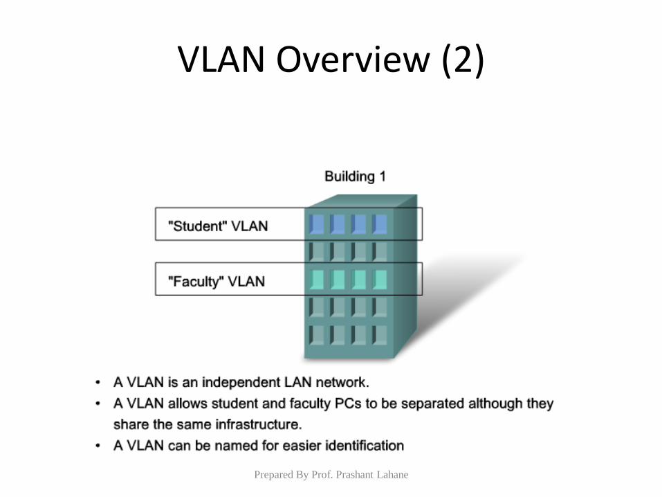
VLAN Overview (2)
Prepared By Prof. Prashant Lahane
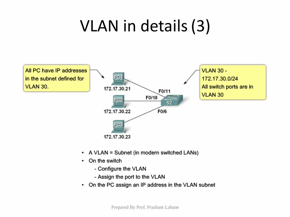
VLAN in details (1)
• A VLAN is a logically separate IP subnetwork.
• VLANs allow multiple IP networks and subnets to exist on the same switched network.
• For computers to communicate on the same VLAN, each must have an IP address and a subnet mask that is consistent for that VLAN.
• The switch has to be configured with the VLAN and each port in the VLAN must be assigned to the VLAN.
Prepared By Prof. Prashant Lahane
VLAN in details (2)
• A switch port with a singular VLAN configured on it is called an access port.
• Remember, just because two computers are physically connected to the same switch does not mean that they can communicate.
• Devices on two separate networks and subnets must communicate via a router (Layer 3), whether or not VLANs are used.
Prepared By Prof. Prashant Lahane
VLAN in details (3)
Prepared By Prof. Prashant Lahane
Benefits of VLAN (1)
• Security - Groups that have sensitive data are separated from the rest of the network, decreasing the chances of confidential information breaches.
– Faculty computers are on VLAN 10 and completely separated from student and guest data traffic.
• Cost reduction - Cost savings result from less need for expensive network upgrades and more efficient use of existing bandwidth and uplinks.
Prepared By Prof. Prashant Lahane
Benefits of VLAN (2)
• Higher performance - Dividing flat Layer 2 networks into multiple logical workgroups (broadcast domains) reduces unnecessary traffic on the network and boosts performance.
• Broadcast storm mitigation - Dividing a network into VLANs reduces the number of devices that may participate in a broadcast storm.
– In the figure you can see that although there are six computers on this network, there are only three broadcast domains: Faculty, Student, and Guest.
Prepared By Prof. Prashant Lahane
Applications of VLAN
• Simpler project or application management - VLANs aggregate users and network devices to support business or geographic requirements. – Having separate functions makes managing a
project or working with a specialized application easier, for example, an e-learning development platform for faculty.
– It is also easier to determine the scope of the effects of upgrading network services.
Prepared By Prof. Prashant Lahane