unit ii - mr.rajiv bhandari | "never defeat people just win … ii overview of wireless...
TRANSCRIPT

Unit II
Overview of Wireless Networks
10/1/2014 1 Prof. Prashant Lahane
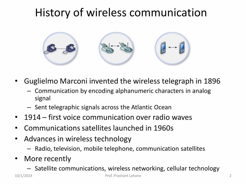
History of wireless communication
• Guglielmo Marconi invented the wireless telegraph in 1896 – Communication by encoding alphanumeric characters in analog
signal
– Sent telegraphic signals across the Atlantic Ocean
• 1914 – first voice communication over radio waves
• Communications satellites launched in 1960s
• Advances in wireless technology – Radio, television, mobile telephone, communication satellites
• More recently – Satellite communications, wireless networking, cellular technology
10/1/2014 2 Prof. Prashant Lahane

What is Wireless Communication ?
• Transmitting voice and data using electromagnetic waves in open space (atmosphere)
• Electromagnetic waves • Travel at speed of light (c = 3x10⁸ m/s)
• Has a frequency (f) and wavelength (l)
» c = f x l
• Higher frequency means higher energy photons
• The higher the energy photon the more penetrating is the radiation
10/1/2014 3 Prof. Prashant Lahane

Types of wireless communication
celullar wireless computer network radio service
10/1/2014 4 Prof. Prashant Lahane

Electromagnetic Waves & the Electromagnetic Spectrum
10/1/2014 5 Prof. Prashant Lahane

Electromagnetic Waves • Transverse waves without a medium!
• (They can travel through empty space)
10/1/2014 6 Prof. Prashant Lahane

• They travel as vibrations in electrical and magnetic fields.
– Have some magnetic and some electrical properties to them.
10/1/2014 7 Prof. Prashant Lahane

• When an electric field changes, so does the magnetic field. The changing magnetic field causes the electric field to change. When one field vibrates—so does the other.
• RESULT-An electromagnetic wave.
10/1/2014 8 Prof. Prashant Lahane
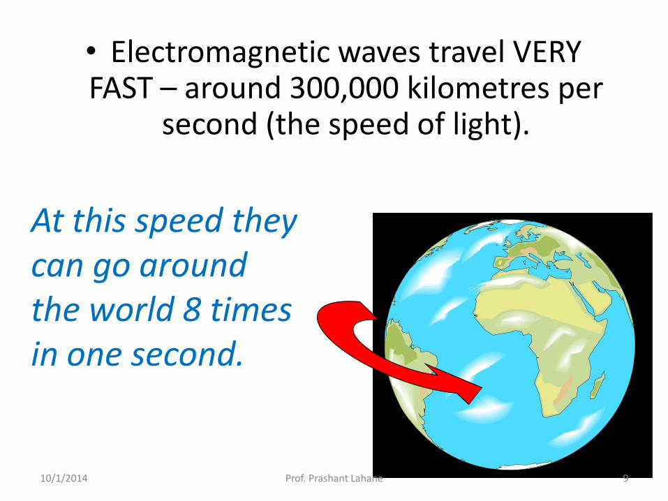
• Electromagnetic waves travel VERY FAST – around 300,000 kilometres per
second (the speed of light).
At this speed they can go around the world 8 times in one second.
10/1/2014 9 Prof. Prashant Lahane

• Waves or Particles?
• Electromagnetic radiation has properties of waves but also can be thought of as a stream of particles.
– Example: Light • Light as a wave: Light behaves as a transverse wave
which we can filter using polarized lenses.
• Light as particles (photons): When directed at a substance light can knock electrons off of a substance (Photoelectric effect)
10/1/2014 10 Prof. Prashant Lahane

• Electromagnetic Spectrum—name for the range of electromagnetic waves when placed in order of increasing frequency
RADIO
WAVES
MICROWAVES
INFRARED
RAYS
VISIBLE LIGHT
ULTRAVIOLET
RAYS
X-RAYS
GAMMA
RAYS
10/1/2014 11 Prof. Prashant Lahane
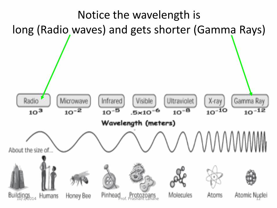
Notice the wavelength is long (Radio waves) and gets shorter (Gamma Rays)
10/1/2014 12 Prof. Prashant Lahane

10/1/2014 13 Prof. Prashant Lahane

RADIO WAVES
• Have the longest wavelengths and
lowest frequencies of all the
electromagnetic waves.
10/1/2014 14 Prof. Prashant Lahane

• Global Positioning Systems (GPS) measures the time it takes a radio wave to travel from several
satellites to the receiver, determining the distance to each satellite.
10/1/2014 15 Prof. Prashant Lahane

• A radio picks up radio waves through an antenna and converts it to sound waves.
– Each radio station in an area broadcasts at a different frequency.
• # on radio dial tells frequency.
10/1/2014 16 Prof. Prashant Lahane

MRI (MAGNETIC RESONACE IMAGING)
Uses Short wave radio waves with a magnet to create an image.
10/1/2014 17 Prof. Prashant Lahane

MICROWAVES
• Have the shortest wavelengths and
the highest frequency of the
radio waves.
10/1/2014 18 Prof. Prashant Lahane

Used in microwave ovens.
• Waves transfer energy to the water in the food causing them to vibrate which in turn transfers energy in the form of heat to the food.
10/1/2014 19 Prof. Prashant Lahane
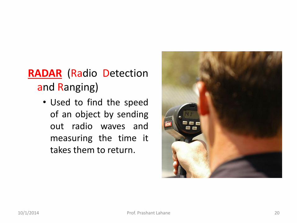
RADAR (Radio Detection and Ranging)
• Used to find the speed of an object by sending out radio waves and measuring the time it takes them to return.
10/1/2014 20 Prof. Prashant Lahane

INFRARED RAYS
• Infrared= below red
• Shorter wavelength and higher frequency than microwaves.
10/1/2014 21 Prof. Prashant Lahane
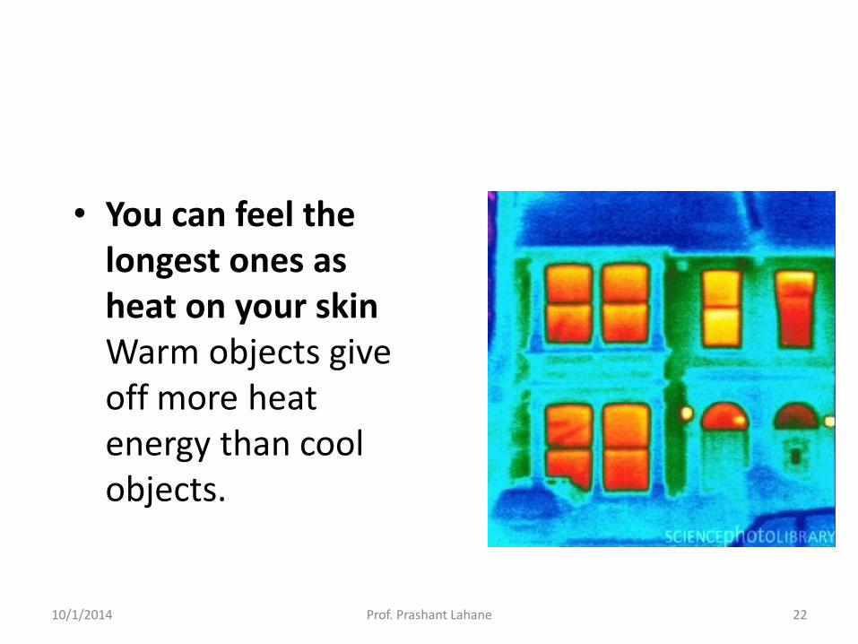
• You can feel the longest ones as heat on your skin Warm objects give off more heat energy than cool objects.
10/1/2014 22 Prof. Prashant Lahane

Thermogram—a picture that shows regions of different temperatures in the body. Temperatures are calculated by the
amount of infrared radiation given off.
•Therefore people give off infrared rays.
•Heat lamps give off infrared waves.
10/1/2014 23 Prof. Prashant Lahane

VISIBLE LIGHT
• Shorter wavelength and higher frequency than infrared rays.
• Electromagnetic waves we can see.
• Longest wavelength= red light
• Shortest wavelength= violet (purple) light
10/1/2014 24 Prof. Prashant Lahane

Spread Spectrum Systems
10/1/2014 25 Prof. Prashant Lahane

Spread Spectrum
• Analog or digital data
• Analog signal
• Spread data over wide bandwidth
• Makes jamming and interception harder
• Frequency hoping
– Signal broadcast over seemingly random series of frequencies
• Direct Sequence
– Each bit is represented by multiple bits in transmitted signal
– Chipping code
10/1/2014 26 Prof. Prashant Lahane

Spread Spectrum Concept
• Input fed into channel encoder – Produces narrow bandwidth analog signal around central frequency
• Signal modulated using sequence of digits – Spreading code/sequence
– Typically generated by pseudonoise/pseudorandom number generator
• Increases bandwidth significantly – Spreads spectrum
• Receiver uses same sequence to demodulate signal
• Demodulated signal fed into channel decoder
10/1/2014 27 Prof. Prashant Lahane

General Model of Spread Spectrum System
10/1/2014 28 Prof. Prashant Lahane
Gains
• Immunity from various noise and multipath distortion – Including jamming
• Can hide/encrypt signals – Only receiver who knows spreading code can retrieve
signal
• Several users can share same higher bandwidth with little interference – Cellular telephones – Code division multiplexing (CDM) – Code division multiple access (CDMA)
10/1/2014 29 Prof. Prashant Lahane

Modem Switching Techniques
10/1/2014 30 Prof. Prashant Lahane

Switching Techniques
• In large networks there might be multiple
paths linking sender and receiver.
• Information may be switched as it travels
through various communication channels.
• There are three typical switching techniques
available for digital traffic.
• Circuit Switching
• Message Switching
• Packet Switching
10/1/2014 31 Prof. Prashant Lahane

Circuit Switching
• Circuit switching is a technique that directly connects the sender and the receiver in an unbroken path.
• Telephone switching equipment establishes a path that connects the caller to the receiver by physical connection.
• Once a connection is established, a dedicated path exists between both ends until the connection is terminated.
• Routing decisions must be made when the circuit is first established, but there are no decisions made after that time.
10/1/2014 32 Prof. Prashant Lahane
Circuit switching Advantages:
• The communication channel (once established) is
dedicated.
Disadvantages:
• Possible long wait to establish a connection,
(10 seconds, more on long- distance or international
calls) during which no data can be transmitted.
• More expensive than any other switching techniques,
because a dedicated path is required for each
connection.
• Inefficient use of the communication channel,
because the channel is not used when the connected
systems are not using it.
10/1/2014 34 Prof. Prashant Lahane

Message Switching
• With message switching there is no need to establish a dedicated path between two stations.
• When a station sends a message, the destination address is appended to the message.
• The message is then transmitted through the network, from node to node.
• Each node receives the entire message, stores it on disk, and then transmits the message to the next node.
• This type of network is called a store-and-forward network.
10/1/2014 35 Prof. Prashant Lahane

Message Switching
• A message-switching node is typically a general-purpose computer.
• The device needs sufficient secondary-storage capacity to store the
incoming messages, which could be long.
• A time delay is introduced using this type of scheme due to store- and-
forward time, plus the time required to find the next node in the
transmission path.
10/1/2014 36 Prof. Prashant Lahane

Message Switching
Advantages:
• Channel efficiency can be greater compared to circuit-
switched systems, because more devices are sharing
the channel.
• Traffic congestion can be reduced, because messages
may be temporarily stored in route.
• Message priorities can be established due to store-and-
forward technique.
• Message broadcasting can be achieved with the use of
broadcast address appended in the message.
10/1/2014 37 Prof. Prashant Lahane

Message Switching
Disadvantages
• Message switching is not compatible with
interactive applications.
• Store-and-forward devices are expensive,
because they must have large disks to hold
potentially long messages.
10/1/2014 38 Prof. Prashant Lahane

Packet Switching
• It tries to combine the advantages of message and circuit switching and
to minimize the disadvantages of both.
• There are two methods of packet switching: Datagram and virtual
circuit.
10/1/2014 39 Prof. Prashant Lahane
Packet Switching
• In both packet switching methods, a message is broken
into small parts, called packets.
• Each packet is tagged with appropriate source and
destination addresses.
• Since packets have a strictly defined maximum length,
they can be stored in main memory instead of disk,
therefore access delay and cost are minimized.
• Also the transmission speeds, between nodes, are
optimized.
• With current technology, packets are generally accepted
onto the network on a first-come, first-served basis. If the
network becomes overloaded, packets are delayed or
discarded (``dropped''). 10/1/2014 40 Prof. Prashant Lahane

Packet switching • Analog signal from your phone is converted into a digital data
stream.
• That series of digital bits is then divided into relatively tiny clusters of bits, called packets.
• Each packet has at its beginning the digital address -- a long number -- to which it is being sent. The system blasts out all those tiny packets, as fast as it can, and they travel across the nation's digital backbone systems to their destination: the telephone, or rather the telephone system, of the person you're calling.
• They do not necessarily travel together; they do not travel sequentially. They don't even all travel via the same route. But eventually they arrive at the right point -- that digital address added to the front of each string of digital data -- and at their destination are reassembled into the correct order, then converted to analog form, so your friend can understand what you're saying.
10/1/2014 42 Prof. Prashant Lahane
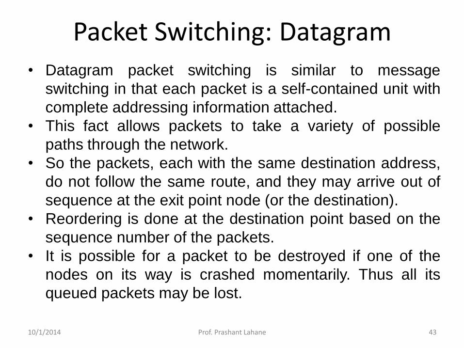
Packet Switching: Datagram • Datagram packet switching is similar to message
switching in that each packet is a self-contained unit with
complete addressing information attached.
• This fact allows packets to take a variety of possible
paths through the network.
• So the packets, each with the same destination address,
do not follow the same route, and they may arrive out of
sequence at the exit point node (or the destination).
• Reordering is done at the destination point based on the
sequence number of the packets.
• It is possible for a packet to be destroyed if one of the
nodes on its way is crashed momentarily. Thus all its
queued packets may be lost.
10/1/2014 43 Prof. Prashant Lahane

Packet Switching: Virtual Circuit
• In the virtual circuit approach, a preplanned route is
established before any data packets are sent.
• A logical connection is established when o a sender send a "call request packet" to the receiver and
o the receiver send back an acknowledge packet "call accepted
packet" to the sender if the receiver agrees on
conversational parameters.
• The conversational parameters can be maximum packet
sizes, path to be taken, and other variables necessary to
establish and maintain the conversation.
• Virtual circuits imply acknowledgements, flow control, and
error control, so virtual circuits are reliable.
• That is, they have the capability to inform upper-protocol
layers if a transmission problem occurs.
10/1/2014 44 Prof. Prashant Lahane

Packet Switching:Virtual Circuit • In virtual circuit, the route between stations does not
mean that this is a dedicated path, as in circuit
switching.
• A packet is still buffered at each node and queued for
output over a line.
• The difference between virtual circuit and datagram
approaches:
• With virtual circuit, the node does not need to make
a routing decision for each packet.
• It is made only once for all packets using that virtual
circuit.
10/1/2014 45 Prof. Prashant Lahane

Packet Switching: Virtual Circuit
VC guarantees that
• the packets sent; arrive in the order sent
• with no duplicates or omissions
• with no errors (with high probability) regardless of how they are implemented internally.
10/1/2014 46 Prof. Prashant Lahane
Advantages of packet switching Advantages:
1. Packet switching is cost effective, because switching
devices do not need massive amount of secondary storage.
2. Packet switching offers improved delay characteristics,
because there are no long messages in the queue
(maximum packet size is fixed).
3. Packet can be rerouted if there is any problem, such as,
busy or disabled links.
4. The advantage of packet switching is that many network
users can share the same channel at the same time. Packet
switching can maximize link efficiency by making optimal
use of link bandwidth.
10/1/2014 47 Prof. Prashant Lahane
Disadvantages of packet switching Disadvantages:
1. Protocols for packet switching are typically more
complex.
2. It can add some initial costs in implementation.
3. If packet is lost, sender needs to retransmit the data.
4. Another disadvantage is that packet-switched systems
still can’t deliver the same quality as dedicated circuits
in applications requiring very little delay - like voice
conversations or moving images.
10/1/2014 48 Prof. Prashant Lahane

Hardware Components
10/1/2014 49 Prof. Prashant Lahane
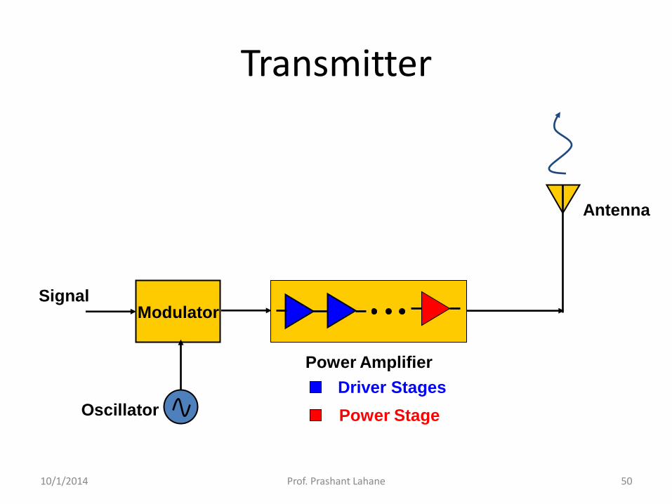
Transmitter
Modulator
Power Amplifier
Driver Stages
Power Stage
Antenna
Oscillator
Signal
10/1/2014 50 Prof. Prashant Lahane

Receiver
Low Noise Amplifier
Low Noise Amplifier
Gain-Stage Amplifier
Filter
Antenna Oscillator
Mixer
Filter
10/1/2014 51 Prof. Prashant Lahane

Transceiver = Transmitter + Receiver
Modulator
Power Amplifier
Antenna
Oscillator
Signal
Low Noise Amplifier
Filter
Mixer
Filter
10/1/2014 52 Prof. Prashant Lahane

Access Points
• An access point (AP) is a transceiver that connects to an Ethernet cable
– It bridges the wireless network with the wired network
• Not all wireless networks connect to a wired network
– Most companies have Wireless LANs (WLANs) that connect to their wired network topology
10/1/2014 53 Prof. Prashant Lahane

Access Points
• The AP is where channels are configured
• An AP enables users to connect to a LAN using wireless technology
– An AP is available only within a defined area
10/1/2014 54 Prof. Prashant Lahane

Configuring an Access Point
• Configuring an AP varies depending on the hardware
– Most devices allow access through any Web browser
– Enter IP address on your Web browser and provide your user logon name and password
10/1/2014 55 Prof. Prashant Lahane

Wireless Router
• A wireless router includes an access point, a router, and a switch
10/1/2014 56 Prof. Prashant Lahane

• A wireless router is a device that performs the
functions of a router but also includes the functions of
a wireless access point.
• It is commonly used to provide access to the Internet
or a computer network.
• It does not require a wired link, as the connection is
made wirelessly, via radio waves.
• It can function in a wired LAN (local area network),
in a wireless-only LAN (WLAN), or in a mixed
wired/wireless network, depending on the
manufacturer and model.
Wireless Router
10/1/2014 57 Prof. Prashant Lahane

OSI Model Layers
Physical
Data Link
Network
Transport
Session
Presentation
Application
Transmission of binary data of a medium
Transfer of units of information, framing, and error checking
Delivery of packets of information, which includes routing
Provision for end-to-end reliable and unreliable delivery
Establishment and maintenance of sessions
Data formatting and encryption
Network applications such as file transfer and terminal
emulation
OSI layer Function provided
Layer 7 - presents application to users; Layers 3-6 - provides Common Language for
communication; Layers 1-2 - provides the physical connection.
10/1/2014 58 Prof. Prashant Lahane

Data Link Layer
• The Data Link Layer addresses groups of bits to a device located across a single physical transmission path, called a link.
• Each group of bits that the Data Link Layer transmits is called a frame.
• To form a frame, the Data Link Layer encapsulates a Network Layer packet within a header and trailer.
• The header contains the hardware address of the destination node.
• The trailer contains a Frame Check Sequence (FCS) value that the receiving node uses for error detection.
• The Data Link Layer is the only OSI layer that adds a trailer to the data it transmits.
10/1/2014 59 Prof. Prashant Lahane

Data Link Layer
• Each frame carries a packet of data across a single physical link.
• The encapsulated packet does not change, but a new frame is built around the packet for the trip across each link.
• Thus, we often say that the Data Link Layer is concerned with transmitting data to the next node in the network.
• Popular Data Link protocols include:
– High-Level Data Link Control (HDLC)
– Synchronous Data Link Control (SDLC)
– Link Access Procedure for D channel (LAPD), used in ISDN
– LAN protocols such as Ethernet, Token Ring, and FDDI
– WAN protocols such as frame relay, ATM, and ISDN 10/1/2014 60 Prof. Prashant Lahane
• Services Provided to the Network Layer
• Framing
• Error Control
• Flow Control
Data Link Layer Design Issues
10/1/2014 61 Prof. Prashant Lahane

• Provide service interface to the network layer
• Dealing with transmission errors
• Regulating data flow
• Slow receivers not swamped by fast senders
Functions of the Data Link Layer
10/1/2014 62 Prof. Prashant Lahane

• Unacknowledged Connectionless service
• Acknowledged Connectionless service
• Acknowledged Connection-Oriented service
Types of services provided to the Network Layer
10/1/2014 63 Prof. Prashant Lahane

• Losses are taken care of at higher layers
• Used on reliable medium like coax cables or optical fiber, where the error rate is low.
• Appropriate for voice, where delay is worse than bad data.
Unacknowledged Connectionless service
10/1/2014 64 Prof. Prashant Lahane

• Useful on unreliable medium like wireless.
• Acknowledgements add delays.
• Adding ack in the DLL rather than in the NL is just an optimization and not a requirement. Leaving it for the NL is inefficient as a large message (packet) has to be resent in contrast to small frames.
• On reliable channels, like fiber, the overhead associated with the ack is not justified.
Acknowledged Connectionless service
10/1/2014 65 Prof. Prashant Lahane

• Most reliable,
• Guaranteed service –
– Each frame sent is indeed received
– Each frame is received exactly once
– Frames are received in order
• Special care has to be taken to ensure this in connectionless services
Acknowledged Connection-oriented service
10/1/2014 66 Prof. Prashant Lahane

• Character Count
• Flag bytes with byte stuffing
• Flag bytes with bit stuffing
Framing
10/1/2014 67 Prof. Prashant Lahane
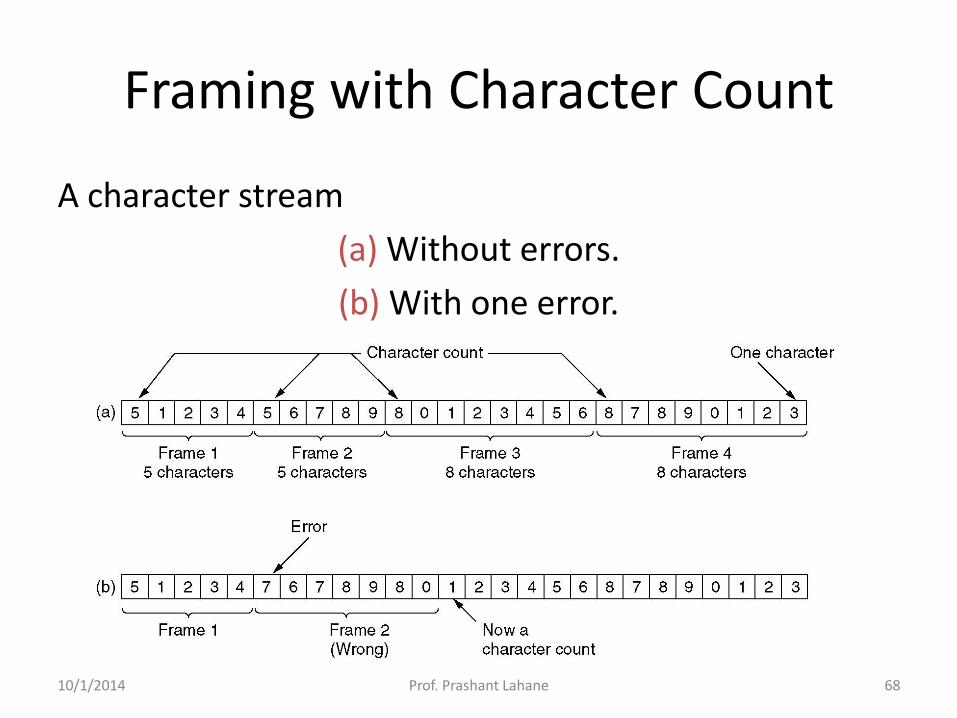
A character stream
(a) Without errors.
(b) With one error.
Framing with Character Count
10/1/2014 68 Prof. Prashant Lahane

• What if the count is garbled
• Even if with checksum, the receiver knows that the frame is bad, there is no way to tell where the next frame starts.
• Asking for retransmission doesn’t help either because the start of the retransmitted frame is not known
• No longer used
Problem with Framing with CC
10/1/2014 69 Prof. Prashant Lahane

Framing with byte stuffing
10/1/2014 70 Prof. Prashant Lahane
• Problem:
– fixed character size: assumes character size to be 8 bits: can’t handle heterogeneous environment.
Framing with byte stuffing
10/1/2014 71 Prof. Prashant Lahane

Bit stuffing (a) The original data. (b) The data as they appear on the line. (c) The data as they are stored in receiver’s memory after
destuffing.
Framing with bit stuffing
10/1/2014 72 Prof. Prashant Lahane

Flow and Error Control
10/1/2014 73 Prof. Prashant Lahane

Flow Control
• Flow control coordinates the amount of data that can be sent before receiving acknowledgement
• It is one of the most important functions of data link layer.
• Flow control is a set of procedures that tells the sender how much data it can transmit before it must wait for an acknowledgement from the receiver.
• Receiver has a limited speed at which it can process incoming data and a limited amount of memory in which to store incoming data.
• Receiver must inform the sender before the limits are reached and request that the transmitter to send fewer frames or stop temporarily.
• Since the rate of processing is often slower than the rate of transmission, receiver has a block of memory (buffer) for storing incoming data until they are processed.
10/1/2014 74 Prof. Prashant Lahane

Error Control
• Error control includes both error detection and error correction.
• It allows the receiver to inform the sender if a frame is lost or damaged during transmission and coordinates the retransmission of those frames by the sender.
• Error control in the data link layer is based on automatic repeat request (ARQ). Whenever an error is detected, specified frames are retransmitted.
10/1/2014 75 Prof. Prashant Lahane

Taxonomy of protocols
10/1/2014 76 Prof. Prashant Lahane

NOISELESS CHANNELS
Let us first assume we have an ideal channel in which
no frames are lost, duplicated, or corrupted. We
introduce two protocols for this type of channel.
Simplest Protocol
Stop-and-Wait Protocol
10/1/2014 77 Prof. Prashant Lahane

The design of the simplest protocol with no flow or error control
10/1/2014 78 Prof. Prashant Lahane

• The sender sends a sequence
of frames without even
thinking about the receiver.
• To send three frames, three
events occur at the sender site
and three events at the
receiver site.
• Note that the data frames are
shown by tilted boxes; the
height of the box defines the
transmission time difference
between the first bit and the
last bit in the frame.
Simplest Protocol
10/1/2014 79 Prof. Prashant Lahane

Design of Stop-and-Wait Protocol
10/1/2014 80 Prof. Prashant Lahane

• The sender sends
one frame and waits
for feedback from
the receiver.
• When the ACK
arrives, the sender
sends the next
frame.
Stop-and-Wait Protocol
10/1/2014 81 Prof. Prashant Lahane

NOISY CHANNELS
Although the Stop-and-Wait Protocol gives us an idea of
how to add flow control to its predecessor, noiseless
channels are nonexistent. We discuss three protocols in
this section that use error control.
Stop-and-Wait Automatic Repeat Request
Go-Back-N Automatic Repeat Request
Selective Repeat Automatic Repeat Request
10/1/2014 82 Prof. Prashant Lahane

Error correction in Stop-and-Wait ARQ is
done by keeping a copy of the sent frame
and retransmitting of the frame when the
timer expires.
Note
10/1/2014 83 Prof. Prashant Lahane

Sequence Numbers
• Frames from a sender are numbered sequentially.
• We need to set a limit since we need to include the sequence number of each frame in the header.
• If the header of the frame allows m bits for sequence number, the sequence numbers range from 0 to 2 m – 1. for m = 3, sequence numbers are: 1, 2, 3, 4, 5, 6, 7.
• We can repeat the sequence number.
• Sequence numbers are:
0, 1, 2, 3, 4, 5, 6, 7, 0, 1, 2, 3, 4, 5, 6, 7, 0, 1, …
10/1/2014 84 Prof. Prashant Lahane

In Stop-and-Wait ARQ, we use sequence
numbers to number the frames.
The sequence numbers are based on modulo-2
arithmetic.
Note
10/1/2014 85 Prof. Prashant Lahane

In Stop-and-Wait ARQ, the
acknowledgment number always
announces in modulo-2 arithmetic the
sequence number of the next frame
expected.
Note
10/1/2014 86 Prof. Prashant Lahane

Design of the Stop-and-Wait ARQ Protocol
10/1/2014 87 Prof. Prashant Lahane

Stop-and-Wait ARQ Protocol
• Frame 0 is sent and
acknowledged.
• Frame 1 is lost and resent
after the time-out.
• The resent frame 1 is
acknowledged and the timer
stops.
• Frame 0 is sent and
acknowledged, but the
acknowledgment is lost.
• The sender has no idea if the
frame or the acknowledgment
is lost, so after the time-out, it
resends frame 0, which is
acknowledged.
10/1/2014 88 Prof. Prashant Lahane

In the Go-Back-N Protocol, the sequence
numbers are modulo 2m,
where m is the size of the sequence
number field in bits.
Note
10/1/2014 89 Prof. Prashant Lahane

Send (sliding) window for Go-Back-N ARQ
10/1/2014 90 Prof. Prashant Lahane

The send window is an abstract concept
defining an imaginary box of size 2m − 1
with three variables: Sf, Sn, and Ssize.
Note
10/1/2014 91 Prof. Prashant Lahane

The send window can slide one
or more slots when a valid acknowledgment
arrives.
Note
10/1/2014 92 Prof. Prashant Lahane
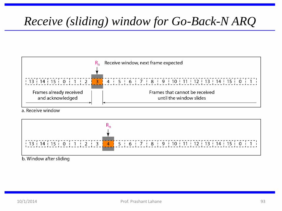
Receive (sliding) window for Go-Back-N ARQ
10/1/2014 93 Prof. Prashant Lahane

The receive window is an abstract concept
defining an imaginary box
of size 1 with one single variable Rn.
The window slides
when a correct frame has arrived; sliding
occurs one slot at a time.
Note
10/1/2014 94 Prof. Prashant Lahane

Design of Go-Back-N ARQ
10/1/2014 95 Prof. Prashant Lahane

Window size for Go-Back-N ARQ
10/1/2014 96 Prof. Prashant Lahane

In Go-Back-N ARQ, the size of the send
window must be less than 2m;
the size of the receiver window
is always 1.
Note
10/1/2014 97 Prof. Prashant Lahane

• This is an example of a case where
the forward channel is reliable,
but the reverse is not.
• No data frames are lost, but some
ACKs are delayed and one is lost.
• The example also shows how
cumulative acknowledgments can
help if acknowledgments are
delayed or lost.
• After initialization, there are seven
sender events.
• Request events are triggered by
data from the network layer;
arrival events are triggered by
acknowledgments from the
physical layer.
• There is no time-out event here
because all outstanding frames are
acknowledged before the timer
expires. Note that although ACK 2
is lost, ACK 3 serves as both ACK
2 and ACK 3.
10/1/2014 98 Prof. Prashant Lahane

• NEXT slide shows what happens when a frame is lost. Frames
0, 1, 2, and 3 are sent. However, frame 1 is lost.
• The receiver receives frames 2 and 3, but they are discarded
because they are received out of order.
• The sender receives no acknowledgment about frames 1, 2, or
3. Its timer finally expires.
• The sender sends all outstanding frames (1, 2, and 3) because
it does not know what is wrong.
• Note that the resending of frames 1, 2, and 3 is the response
to one single event. When the sender is responding to this
event, it cannot accept the triggering of other events. This
means that when ACK 2 arrives, the sender is still busy with
sending frame 3.
Example of Forward Channel Not Reliable
10/1/2014 99 Prof. Prashant Lahane

• The physical layer must wait until this event is
completed and the data link layer goes back to its
sleeping state.
• We have shown a vertical line to indicate the delay.
It is the same story with ACK 3; but when ACK 3
arrives, the sender is busy responding to ACK 2.
• It happens again when ACK 4 arrives.
• Note that before the second timer expires, all
outstanding frames have been sent and the timer is
stopped.
Example of Forward Channel Not Reliable
(cont…)
10/1/2014 100 Prof. Prashant Lahane

Example of Forward channel not reliable
10/1/2014 101 Prof. Prashant Lahane

Stop-and-Wait ARQ is a special case of Go-
Back-N ARQ in which the size of the send
window is 1.
Note
10/1/2014 102 Prof. Prashant Lahane

Send window for Selective Repeat ARQ
10/1/2014 103 Prof. Prashant Lahane

Receive window for Selective Repeat ARQ
10/1/2014 104 Prof. Prashant Lahane

Design of Selective Repeat ARQ
10/1/2014 105 Prof. Prashant Lahane

Selective Repeat ARQ, window size
10/1/2014 106 Prof. Prashant Lahane

In Selective Repeat ARQ, the size of the
sender and receiver window
must be at most one-half of 2m.
Note
10/1/2014 107 Prof. Prashant Lahane

108
The Medium Access Control Sublayer
10/1/2014 Prof. Prashant Lahane
109
The Medium Access Control Sublayer
• In the literature, broadcast channels are sometimes referred to as multiaccess channels or random access channels.
• The protocols used to determine who goes next on a multiaccess channel belong to a sublayer of the data link layer called the MAC (Medium Access Control) sublayer.
10/1/2014 Prof. Prashant Lahane
110
The Channel Allocation Problem
• To allocate a single broadcast channel among competing users, we can use:
– Static Channel Allocation in LANs and MANs
– Dynamic Channel Allocation in LANs and MANs
10/1/2014 Prof. Prashant Lahane
111
Static Channel Allocation in LANs and MANs
• Frequency Division Multiplexing (FDM) is an example of static channel allocation where the bandwidth is divided among a number of N users.
• When there is only a small and constant number of users, each of which has a heavy (buffered) load of traffic (e.g., carriers' switching offices), FDM is a simple and efficient allocation mechanism.
10/1/2014 Prof. Prashant Lahane

Static Channel Allocation (cont…)
However, when the number of senders is large
and continuously varying or the traffic is bursty,
FDM presents some problems.
1) when fewer than N users are currently interested in communicating, a large piece of valuable spectrum will be wasted.
2) when more users wants to communicate, those who have not been assigned a frequency will be denied permission.
3) even assuming that the number of users could somehow be held constant at N, each user traffic usually changes dynamically over time.
10/1/2014 112 Prof. Prashant Lahane

113
Dynamic Channel Allocation in LANs and MANs
1. Station Model: N independent stations (terminals) exists.
2. Single Channel Assumption: A single channel is available for all communication (send and receive)
3. Collision Assumption: If two frames are transmitted simultaneously, they overlap in time and the resulting signal is garbled (collision). No errors other than those generated by collisions assumed to exist.
10/1/2014 Prof. Prashant Lahane

Dynamic Channel Allocation (cont…)
4. (a) Continuous Time: Frame transmission can begin at any instant.
(b) Slotted Time: Frame transmissions always begin at the start of a slot where the time is divided into discrete slots.
5. (a) Carrier Sense: Stations can tell if the channel is in use before trying to use it.
(b) No Carrier Sense: Stations cannot sense the channel before trying to use it.
10/1/2014 114 Prof. Prashant Lahane

Multiple Access Protocols
10/1/2014 115 Prof. Prashant Lahane

Data link layer divided into two functionality-oriented sublayers
Link Layer Control (LLC)
MAC
Responsible for error
and flow control
Control
Responsible framing
and MAC address and
Multiple Access Control
10/1/2014 116 Prof. Prashant Lahane
Multiple Access
Problem: When two or more nodes transmit at the same time, their frames
will collide and the link bandwidth is wasted during collision
How to coordinate the access of multiple sending/receiving nodes to the
shared link???
• Solution: We need a protocol to coordinate the transmission of the active
nodes
• These protocols are called Medium or Multiple Access Control (MAC)
Protocols belong to a sublayer of the data link layer called MAC (Medium
Access Control)
• What is expected from Multiple Access Protocols:
– Main task is to minimize collisions in order to utilize the bandwidth by:
• Determining when a station can use the link (medium)
• what a station should do when the link is busy
• what the station should do when it is involved in collision
10/1/2014 117 Prof. Prashant Lahane
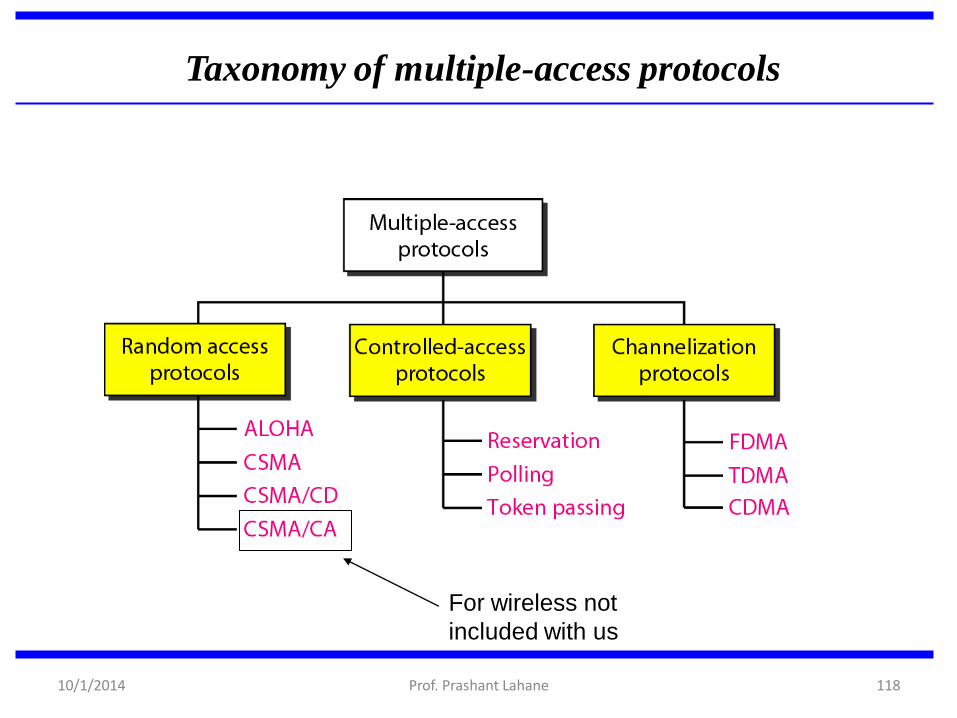
Taxonomy of multiple-access protocols
For wireless not
included with us
10/1/2014 118 Prof. Prashant Lahane
Random Access
• Random Access (or contention) Protocols: – No station is superior to another station and none
is assigned the control over another.
– A station with a frame to be transmitted can use the link directly based on a procedure defined by the protocol to make a decision on whether or not to send.
10/1/2014 119 Prof. Prashant Lahane
ALOHA Protocols • Was designed for wireless LAN and can be used for any
shared medium
• Pure ALOHA Protocol Description – All frames from any station are of fixed length (L bits)
– Stations transmit at equal transmission time (all stations produce frames with equal frame lengths).
– A station that has data can transmit at any time
– After transmitting a frame, the sender waits for an acknowledgment for an amount of time (time out) equal to the maximum round-trip propagation delay = 2* tprop(see next slide)
– If no ACK was received, sender assumes that the frame or ACK has been destroyed and resends that frame after it waits for a random amount of time
– If station fails to receive an ACK after repeated transmissions, it gives up
– Channel utilization or efficiency or Throughput is the percentage of the transmitted frames that arrive successfully (without collisions) or the percentage of the channel bandwidth that will be used for transmitting frames without collisions
– ALOHA Maximum channel utilization is 18% (i.e, if the system produces F frames/s, then 0.18 * F frames will arrive successfully on average without the need of retransmission).
10/1/2014 120 Prof. Prashant Lahane
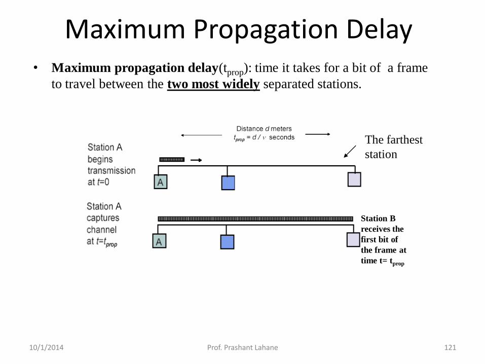
Maximum Propagation Delay • Maximum propagation delay(tprop): time it takes for a bit of a frame
to travel between the two most widely separated stations.
The farthest
station
Station B
receives the
first bit of
the frame at
time t= tprop
10/1/2014 121 Prof. Prashant Lahane

Procedure for ALOHA protocol
10/1/2014 122 Prof. Prashant Lahane

Critical time for pure ALOHA protocol
If the frame transmission time is T sec, then the vulnerable
time is = 2 T sec.
This means no station should send during the T-sec before this
station starts transmission and no station should start sending
during the T-sec period that the current station is sending.
Tfr= Frame
Transmission time
10/1/2014 123 Prof. Prashant Lahane

Pure ALOHA
In pure ALOHA, frames are transmitted at completely arbitrary times. 10/1/2014 124 Prof. Prashant Lahane
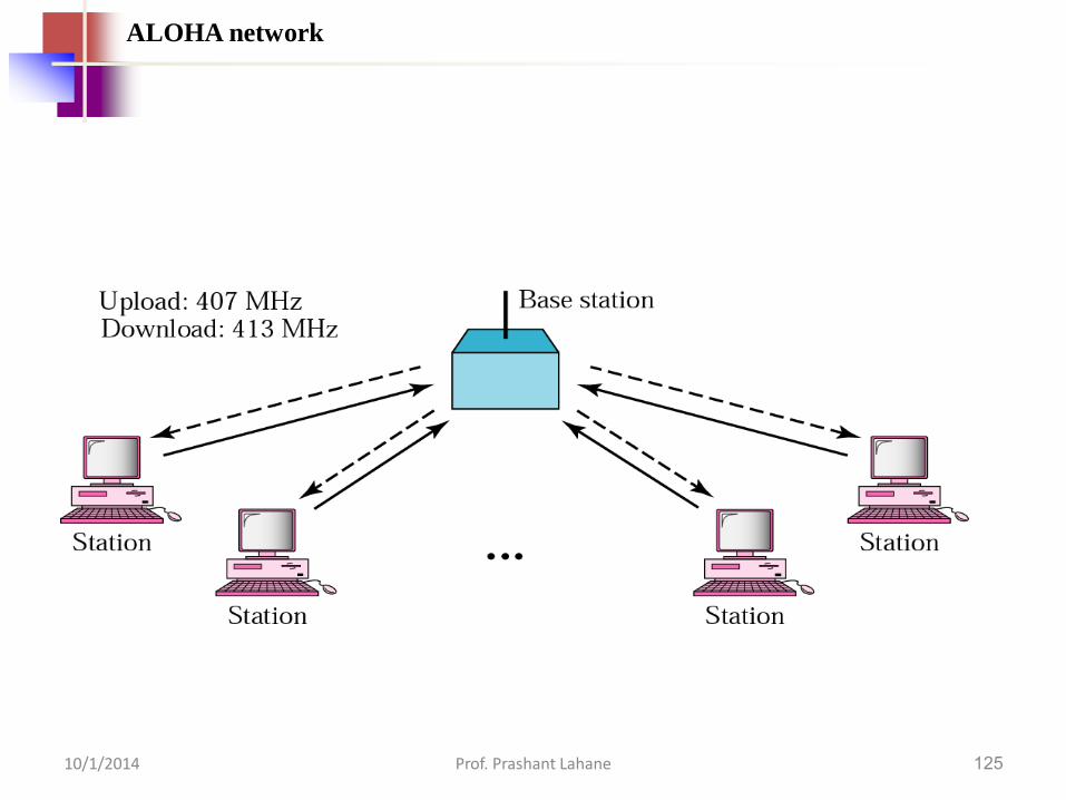
125
ALOHA network
10/1/2014 Prof. Prashant Lahane

126
Procedure for ALOHA protocol
10/1/2014 Prof. Prashant Lahane
Random Access – Slotted ALOHA
• Time is divided into slots equal to a frame transmission
time (Tfr)
• A station can transmit at the beginning of a slot only
• If a station misses the beginning of a slot, it has to wait
until the beginning of the next time slot.
• A central clock or station informs all stations about the
start of a each slot
• Maximum channel utilization is 37%
10/1/2014 127 Prof. Prashant Lahane

In danger time for slotted ALOHA protocol
10/1/2014 128 Prof. Prashant Lahane

Random Access – Slotted
ALOHA
10/1/2014 129 Prof. Prashant Lahane

Advantage of ALOHA protocols
• A node that has frames to be transmitted can transmit
continuously at the full rate of channel (R bps) if it is
the only node with frames
• Simple to be implemented
• No master station is needed to control the medium
Disadvantage
• If (M) nodes want to transmit, many collisions can
occur and the rate allocated for each node will not be on
average R/M bps
• This causes low channel utilization 10/1/2014 130 Prof. Prashant Lahane

Random Access – Carrier Sense Multiple Access (CSMA)
• To improve performance, avoid transmissions that are certain to cause
collisions
• Based on the fact that in LAN propagation time is very small
• If a frame was sent by a station, All stations knows immediately so they can
wait before start sending
– A station with frames to be sent, should sense the medium for the
presence of another transmission (carrier) before it starts its own
transmission
• This can reduce the possibility of collision but it cannot eliminate it.
– Collision can only happen when more than one station begin transmitting
within a short time (the propagation time period)
10/1/2014 131 Prof. Prashant Lahane

Random Access – Carrier Sense Multiple Access
(CSMA)
Vulnerable time for CSMA is the maximum propagation time
The longer the propagation delay, the worse the performance of the
protocol because of the above case.
10/1/2014 132 Prof. Prashant Lahane

CSMA/CD (Collision Detection)
CSMA has an inefficiency:
If a collision has occurred, the channel is unstable until
colliding packets have been fully transmitted
CSMA/CD (Carrier Sense Multiple Access with Collision
Detection) overcomes this as follows:
While transmitting, the sender is listening to medium for
collisions.
Sender stops transmission if collision has occurred
reducing channel wastage .
CSMA/CD is Widely used for bus topology LANs (IEEE 802.3,
Ethernet).
10/1/2014 133 Prof. Prashant Lahane
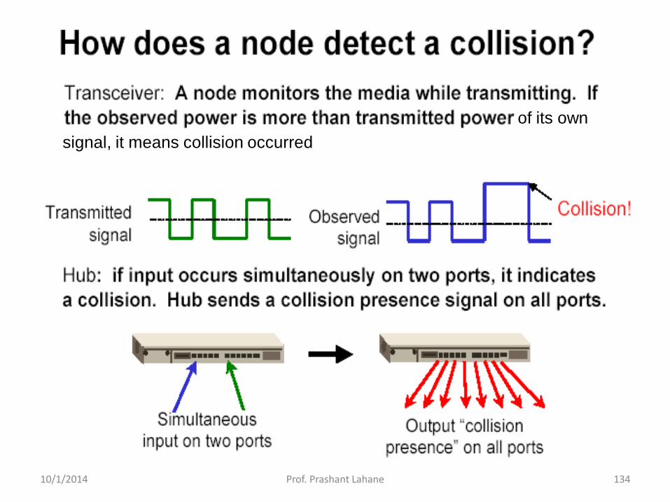
of its own
signal, it means collision occurred
10/1/2014 134 Prof. Prashant Lahane

CSMA/CD Protocol
• If a collision is detected by a station during
its transmission then it should do the
following:
– Abort transmission and
– Transmit a jam signal (48 bit) to notify other stations
of collision so that they will discard the transmitted
frame also to make sure that the collision signal will
stay until detected by the furthest station
– After sending the jam signal, backoff (wait) for a
random amount of time, then
– Transmit the frame again
10/1/2014 135 Prof. Prashant Lahane

CSMA/CD
Restrictions of CSMA / CD:
Packet transmission time should be at least as long as
the time needed to detect a collision (2 * maximum
propagation delay + jam sequence transmission time)
Otherwise, CSMA/CD does not have an advantage over
CSMA
10/1/2014 136 Prof. Prashant Lahane

Carrier Sense Multiple Access with Collision Avoidance (CSMA-CA)
• Procedure
– Similar to CSMA but instead of sending packets control frames are exchanged
– RTS = request to send
– CTS = clear to send
– DATA = actual packet
– ACK = acknowledgement
10/1/2014 137 Prof. Prashant Lahane

Carrier Sense Multiple Access with Collision Avoidance (CSMA-CA)
• Advantages
– Small control frames lessen the cost of collisions (when data is large)
– RTS + CTS provide “virtual” carrier sense which protects against hidden terminal collisions (where A can’t hear B)
A B
10/1/2014 138 Prof. Prashant Lahane

Carrier Sense Multiple Access with Collision Avoidance (CSMA-CA)
• Disadvantages
– Not as efficient as CSMA-CD
– Doesn’t solve all the problems of MAC in wireless networks (more to come)
10/1/2014 139 Prof. Prashant Lahane