universal vdu - americanradiohistory.com · elektor september 1983 myer: foment electrode...
TRANSCRIPT
up to -date electronics for lab and
tr
-universal VDU
auto
71683
1
September 1983
85 p.,14 123p .r1L1
$
PHILIPS _
personal FM
sumer santamber 1g63 AIR -MAIL COPY
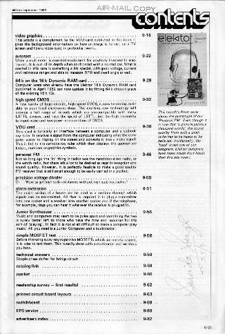
ontEnt -video graphicsThis article is a complement to the VDU card published in this issue. Itgives the background information on how an image is formed on a TVscreen and how a video card, in particular, works.
autotestWhile a multimeter is essential equipment for anybody involved in elec-tronics, it is out of its depth when confronted with a normal car. What isneeded in this case is something a bit special, with good voltage, currentand resistance ranges and able to measure RPM and dwell angle as well.
64 k on the 16k Dynamic RAM cardComputer users who already have the Elektor 16k Dynamic RAM cardpublished in April 1982 can now update it by fitting 64k chips in placeof the existing 16k ICs.
high-speed CMOSA new family of logic circuits, highspeed CMOS, is now becoming avail-able in your local electronics shop. This exciting new technology willprovide a full range of circuits which are pin -compatible with manyLSTTL devices, and have the speed of LSTTL, but the high immunityto input noise and low -power consumption of CMOS.
VDU cardThis card is basically an interface between a computer and a cathoderay tube. It receives a signal from the computer indicating what the com-puter wants to display on the screen and converts it into a video signal.This is fed to the cathode ray tube which then displays the appropriateletters, numbers or graphics symbols.
personal FMNot so long ago the 'in' thing in radios was the matchbox -sized radio, orthe watch radio, but thew left a 101 10 be desired as regards reception andsound quality. However, it is perfectly feasible to make a good qualityFM receiver that is still small enough to be easily carried in a pocket.
precision voltage dividerOr - 'How to get high -stab resistances without high-rtab headachesq
alarm extensionThe mains wiring of a house can be used as a medium through whichsignals can be transmitted. All that is required is to plug a transmitterinto one socket and a receiver into another socket and if the telephone,for example, rings you can hear it wherever the receiver is plugged in.
Junior SynthesizerMusic and computers may seem lobe poles apart and combining the twois surely better left to those who have the time and resources for thissort of 'playing'. In fact it is not at all difficult to make a computer playmusic! All you need is a Junior Computer.and a loudspeaker.
simple MOSE ET testBefore throwing away any expensive MOSFETs which are merely suspect,it is wise 60 641 them. This is easily done with a multimeter and we showyou how.
technical answersSimple phase shifter for bridge circuit
missing link
market
readership survey - f irst results!
printed circuit board layouts
switchboard
EPS service
advertisers index
9-18
9-2
krveis
0
9.22 faVe
9-32per0onal FM,
9-38
9-46
9-50
9-51
9-56
9-58
9-59
9-59
9-60
9-62
9-63
9-68
9-80
9-82
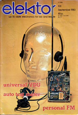
This month's front covershows the prototype of our'Personal FM'. Even though itis Ice that 'a picture paints athousand words', the soundquality from such a smallradio has to be heard to bebelieved. Incidentally, theteed' is not one of ourdesigners. Elektor designershave more inside their headsthan this (we hope).
9-03
elektor september 1983 Myer: foment
ELECTRODEUnderstandably
Britain's most popularand relied -upon
suppliers ofSEMI -CONDUCTORS
I.C.sCOMPONENTS
COMPUTING EQUIPMENTTOOLS, BOXES, CONNECTORS
and much, much moreOUR SUMMER PRICE LIST TELLS ALL
Send for your FREE copy by returnBETTER PRICES. BETTER CHOCE.BETTER SERVICE
ELEaCTROVALUEDept LTegad Mic Mail Q.
D.nd
Shne
raleltn=r7littr ItTanrngaTelre 1:041.B80 eurnwe LaneutZe.Vaneh=1719.7YeririgehOale192,1145
The VIA 6522reveals its secrets
This new hook is an incespers- solely at who u but atable addition to the four books anybody who has a
Compute,otto the Junior one or more 6522s.
Mt it is not aimed
Make the most of your Junior:use eve possible aspect of it.This VIAA 6522 book will helpvou
It will awou abdiyou with:rectional Meat/Outp
ports of this Versa-tile Interface Adapterthe operation of Me two16 -bit Timer/Countershow the integrated ShiftRegister allows you to co
vert Mte from serial to
the obblical irlrocluctbnb a poweeMI system
° Ien trul Ita7a. op., VIAbilities 6527
the detailed operation and
grS*2="'n91Rations and roger"' "-
Elektor Publishers Ltd.
I54-i
Bekla
Price £3.25 Ste postagePm king. , order Weal.
and oforder card at
end of this issue.
GET THE COMPLETE PICTURE
* STILL THE
ONLY
CATALOGUE FOR
THE COMPLETE
RANGE OF
COMPONENTS.
BATTERIES,
CRYSTAL
FILTERS, RF
POWER,
MOSFET, TORO
COILS, CHOKES,
ALPS PLOTTERS,
SOLENOID
CASSETTE
MECHS ETC.
- ORDER YOUR COPY NOW-
COMPONENTS FORELECTRONICS, COMMUNICATIONS & COMPUTING
ambitINTERNATIONAL
csbeA
06
WORLD OF RADIO & ELECTRONICS- GAYA\ LOG U E -
ifP
* FIRST WITH
ON-LINE
COMPUTER
SHOPPING
* FIRST FOR
INNOVATION
* FIRST FOR
VALUE
* FIRST FOR
CHOICE
* RRST FOR
SERVICE
ambit® INTERNATIONAL
00 North SerVuRoad, Brentwood, Essex CMlerISSTel, IConsurne Sales/Rnpuiries) 022,23090MTel, 'Industrial Sales/Enquiries) 0277-231616.Tim S.5194AMBIT G. IlateSehrs (11$232/300 .IA10272-233620
9.08

advertisement elektor september 1983
ROADRUNNER WIRING SYSTEM'1 E.Using this low cost, simpleI Itechnique, you will speed up
your wiring times and produce,a very professional result! IPlease take advantage of our special I
offers and order now!Used extensively in industry this is a truly professional system ideal 2 i
CC -for the home engineer.
EXCLUSIVE OFFERS TO ELEKTOR READERS 1 ct 2EUROI NTRO KIT ROADRUNNER IRON wI 0
ONLYI
ONLY i cc£16.99 £5.9920% SAYING: 20% SAYING!
INORMAL PRICE NORMAL PRICE it52124 5780
Consists: S/Eurocord, wiring pencil, 4 del, Spec - NOY mu 0590 temp iron, suitableWowed enamelled wire bobbins, TCW bobbins, ,e, enener,eu amen, wire, I g gi . E.10 glue strips. 30 press strips,100 solder pins.
...ors ere fully inclusive of carriagerpacking a. VAT I g 11 I
Roadrunner Electronic Product/ Ltd.VISA UNITS THE HASLEMERE INDUSTRIAL ESTATE Im mi
WEYDOWN ROAD, HASLEMERE, SURREY, The name to ememberENGLAND. 0827 1ST,TEL 0428 53850
in electronics.
Full instructions wah
We welcome orders usingAccess & Barclaycard
Electronic manufacturers and Mstobutors
Junior-Paperware
n 2 au e I
The floppy disk is probably the most significantmass storage medium for microcomputers. It seemsincredible that so much data can be stored on asimple plastic disk at such speed and with suchprecision.Unfortunately, it is not enough to just connect afloppy disk drive to a microcompuMr. Withoutsoftware the hardware is useless! Where can youget all the necessary source listings, hex -dumps,and EPROM modifications? In the Elektor Juniorpaperware, of course!Junior paperware I contains the modifications ofthe PM/PME EPROM and the source listings andhex -dump of the software muncher and puncher;Junior paperware 2 gives the source listing of thebootstrap loader for Ohio Scientific Floppys andthe hexdump of the EPROM.
ElektorPublishers Ltd/Canterbury
Price £ 2.00 0 50 p postagepacking per volume.To order, please use the pre-paid order card at the end ofthis issue.
va
so
BUY NOW WHILE STOCKS LAST!ANSGOIM666
;SEE.;4:77iFi:!..iF
FOS 6V LIZ: PZ Ern' n:
0761 pt," P'KrZ"Zir =Z:4 If'
MARCO TRADING, DEPT. KK9
0-I
9.09
advertisement elektor september 1983
B. N.O.S.SAY STOP BUYING BATTERIES!ELECTRONICS
Trtit'n,',Z,;T:,;; LT= `'.','4rvir'Z'end .74"'""7All Mese
V=Z1747:2:f pricy " complete
NICAD BATTERIES
MOH DI 1 - 26-99082
fined ..ith sok., up'
NiCAD CHARGERS
'Abs. AC.1 SAFT MAEDA AA charger, charges 1 to 4 AA cells
n. l'r.)1'1i 14 MCI ALTAI MULTICHARDER, charges 1 to 4 AA, C,5.0
Ocells OM 1 PPP cell. also coil test fcility. 8.50
8.90PC.3 SAFT MAZDA P3charger, charges I or PP3
MC.4 .I.Egecre MULTICHARDER, shames or 4 NAli.
MC.6 JECKSON MULTICHARGER, charges or 4 AA, C.D cells, or 1 0, PP3 colis. 8,50
DO NOT DELAY S NO TO DASNOB EGt InE%'sn'asSst "
All pion Motu. VAT: Goods normally damned by return'POSTAGE FREE ON ALL MAINLAND UN ORDERS OVER 66'
for ord. under E5 please add 60p to cover P &P.
From the world's largest manufacturerof scientific instruments
Beckman nvd rumens are used worldwide M medicine and science, in industryand environmental technology, where precision and reliability are vital.Worlds oldest range of band -held multimeter.
This same perfection M design and manufacture goes into Beckman digitalmultimeters, themselves widely used in testing, measurement, research andengineering because of their accuracy and their intelligent features.
Now the electronics enthusiast has access to the same standard of reliabilityin the T90, T100 end THO models.lAgt_tai nt&dutnale cos
All models undergo 10096 factory testing. Their accuracy is guaranteed to beheld over a long period and reliability is outstanding, timids to fewercomponents and interconnections All components are of the highest quality andInclude a CMOS integrated circuit and gold inlaid switch contacts.
The digital display can be read at a glance, and all functions are selected witha single rotary switch, rather than with confusing rows of push buttons.
Battery life is exceptional- 200 hours at continuous operationThe T90 gives an accuracy of 0.8% Vac and is remarkable value for money at
£43.45 (+VAT).The T100 Is a full range function meter with 0.5% accuracy at 149.00 (+VAT),
while the TOO offers even greater accuracy of 0.25% plus anaudible continuity indicator at 159.00 (+VAT).
BECKMANWorld leaders In multImeters
Beckman Instruments Ltd, Electronic Components UK Sales and Marketing OrganisationMylen House, V Wagon Lane, Sheldon. Birmingham B26 3DU. 021-742 79217elem 336659
I want to go_dIgtiM Please send me: 790 meters at E50.60 pi...vat peel
Two meters at E57.00 (inc. VAT peel 1110 meters alE68.50 linc.VAT pap/
I enclose a cheque/PQ payable to Please send me full data on the Beckman enthusiast'sBeckmanInstrumentsLM tor S mint:meter range. Mob box donnas.Name Andre.
DO NOT SEND TO OAT
9.11
advertisement 983
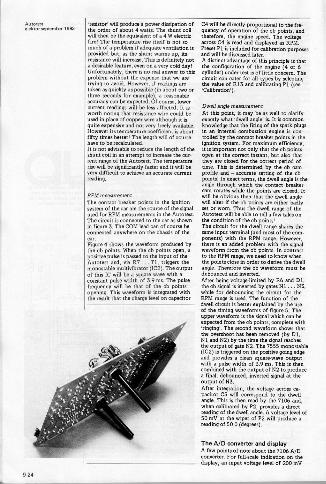
THE COMPLETE PACKAGE!MICROPROFESSOR PLUS THE
STUDENT WORK BOOKWCRO-PRaFfSSOA
Moro -professor=F -x
®-
A low costtool for learning,teaching and prototyping.
Micro -professor is a low-costZ80 based micro computerwhich provides you with aninteresting and inexpensive wayto understand the world ofmicroprocessors.
Micro -Professor is a completehardware and software systemand is a superb learning tool forstudents, hobbyists andmicroprocessor enthusiasts, aswell as an excellent teaching aidfor instructors of electricalengineering and computerscience courses.
Micro -Professor L99.50
E4.00 pup)
Now with the Student WorkBook available Flight offer youthe complete package. An easyto follow manual that will helpfurther your understanding ofmicroprocessors.
Student g.o.'o07,4 £1600
FLIGHTEPB-MPF EPROM
Electronics Ltd. Programming BoardFor all +5V 1KBI2KB/4KB EPROMS' Read/Copy/ List/ VerifyCapability.
SGB-MPFSoundGenerationBoard
Manual play,Auto replay.
Auto rhythm -6 different rhythms,Sound Synthesizerand Hi-li speaker.
SSB-MPF SpeechSynthesizer Board
illoaysec:bonuire'VEr20104.rds
PRT-MPFPrinter BoardMemory dump utility. BASICprogram listing. Z80 disassembler.
rPlease send me ONMicro -Professor £99.50
(-FESS° p&p)Student Work BookSGB-MPF board
06.00E79.00
EPB-MPF boardSSB-MPF board
£99.50E99.50
PRT-MPF board E86.25
I enclose cheque/P.O. for E.
Name ..
Address
.......
Mail OrderonlyPrices include VAT. Pleaseallow 28 days fordetivery. By pnonea
FIJGHTELECTRONICS LTQQucrysideRd.Southampton.HantsSONAD.Te/ex477793.
jel.(0703)34003/27721.
9.17
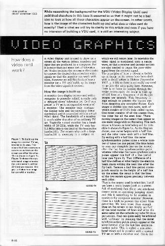
elek[oersepwmber 1983While researching the background for the VDU (Video Display Unit) cardpublished elsewhere in this issue it occurred to us that it might not be a badidea to look at how all those characters appear on the screen. In other words,howls the image of the characters built up and what does a video card doexactly? That is what we will try to clarify in this article and even if you haveno intension of building a VDU card, it is still an interesting subject.
E E -
how does avideo cardwork?
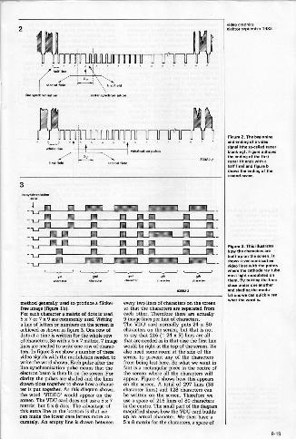
Figure 1. To build up theimage in a normal TV set,interlacing is used. Thismeans that two interwovenrasters are wriwen on thescreen one after the other.This is Mown in figure la.Figure lb shows the non-nterlaced image whereby
the mine raster is written50 timm per [mond. Thisgims a flickereree imagefor use with a monitor.
A video display unit is used to show on awteen all the various letters, numbers andsigns that are produced bye computer. Butit is more than just some sort of televisionset! It also includes the necessary electronicsto convert the desired characters into videosignals so that the monitor can work withthem. However we will first look at how amonitor (or a TV set) builds up its imagefrom the video signals it receives.
How the image is built upA monitor (as a display screen used with acomputer is generally called) is really onlya 'stripped down' television set. Or if youprefer: a TV set is an expanded version of
onitor! The monitor only containshe display tube and the necessary driverelectronics and it is supplied with an actualvideo signal. The bandwidth of a monitoris much wider than that of an ordinary TVset. Typically a good monitor has a band-width of 20 MHz, while the TV only has5.5 MHz (this is the limit of the transmitterbandwidth). The reason why such a largebandwidth is necessary is a subj. to
to
83082.1a
03002-16
which we will return later. In television thevideo signal is modulated onto a carrierwave, so that a receiver and decoder sectionare also needed to regain the pure videosignal from the received signal.The principles of how a television beadsup an image on its screen have been dealtwith in detail before in Elektor (September1977, p. 9-33) so there is not really any needto go into the nitty.gritty here. However,there is no harm in running through themajor points again. An image is built upof 625 lines eta frequency of 25 Hz (25images per second). This frequency ishigh enough to prevent the human eyefrom detecting any annoying flicker. EachGunge is divided into two parts, each ofwI ich consists of 312% lines, called rasters.One raster consists of all the uneven lines,the other has all the even lines. Thesemoving images on the rasters then appear asone static image with no flickering. This tech-nique is known as interlacing and its prin-ciple is shown in figure la. As the diagramshows, one raster begins with a half lineand the other raster ends with a half line.By ending with a half One, the rastersynchronization pulses come a whole num-ber of times the line period (the time takento scan one complete line on the screen)after the last line synchronisation pulse,whereas otherwise the raster synchronizationpulses appear one half of a line periodlater (see figure 2). That difference of ahalf line defines at what height the electronbeam starts writing the next line after thefly -back. Because a half line period corres-ponds exactly to the height of a half lineon the screen the result is that the linesof the two rasters appear precisely betweeneach other.That is the system used in television, but ifwe have a static image (such as a screenfull of numbers) then these two interlaced
t se an annoying 'jumping' effectand this is something to be avoided inmonitors for computer systems! However,there is a trick to prevent this effect fromoccurring. We have more than enoughlines on the screen so we simply use halfof the total number of lines and write thesame raster on the cathode ray tube 50 timesper second. That can quite easily be achievedwith 'software' by ensuring that the rastersynchronization pulses always appear at thesame interval after the last line synchron.ization pulse. This is called a non -inter-laced image and is possible with a normalTV set or with a monitor and this is the
9.18
2
helf line
second field
Ilne synchronisation
Ov
first hem
rawer venchrenisetion
3
-
method generally used to produce s flicker -free image (figure lb).For each character a matrix of dots is used,5 x 7 or 7 x 9 are commonly used. Writinga line of letters or numbers on the screen isachieved as shown in figure E One row ofdots at a time is written for the whole rowof characters. So with a 5 x 7 matrix, 7 imagelines are needed to write one row of charac-ters. In figure 3 we show a number of thesevideo signals with the modulation needed towrite the word shown. Each pulse after theline synchronization pulse means that theelectron beam is then lit on the screen. Forclarity the pulses are shaded and the linesdrawn close together to show how a charac-ter is put together. As this diagram shows,the word 'VIDEO' would appear on thescreen. The VDU card does not use a 507matrix, but 508 dots. The advantage ofthis extra linear the bottom is that wecan make the lower case letters more ac-curately. An empty line is drawn between
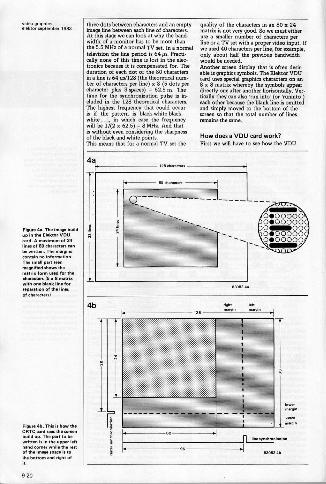
every two lines of characters on the screenen that the characters are separated fromeach other. Therefore there are actually9 image lines per line of characters.The VDU card normally puts 24 x 80characters on the screen, but that is notto my that 216 (= 24 x 9) lines are allthat are needed as in that case the first linewould be right at the top of the screen. Wealso need some room at the side of thescreen to prevent any of the charactersfrom being lost here. So what we want infact its rectangular piece in the centre ofthe screen where all the characters willappear. Figure 4 shows how this appearson the screen. A total of 297 lines (33character lines) and 128 characters canbe written on the screen. Therefore weuse a space 00 216 lines of 80 charactersin the centre. The small part of the diagrammagnified shows how the VDU card buildsup an actual character. We then have a5 x 8 matrix for the characters, a space of
Fianna 2. The beginMngand ending of a videoasset (the socalled resterblanking). Figure a showsthe ending of Me firstraster lit ends with ahalf fine) and figureshows the ending of the'mond raster.
Figure 3. This illustrateshow the characmrs areNull up on the screen. Itshows seven consecutivevideo lines with Me pointswhere the cathode ray tubemu. light modulated onMem. By putting the linesclose maw one anotherand shadMg Me med.-
I s we n Ma Seewhat the word is.
9-19
:=2,7pT, lsaa
Figure aa. The image buildup in the Elektor VDUcard. A maximum of 24lines 01 80 characters canbe written. The marginscontain no information.The small part seenmagnified shows thematrix form us. for the..Mers (5 x 8 matrixwith one blank line forseparation of the linesof characters).
Figure CA This is how MeCRTC ca. sees the screenbuild up. The part to bewritten is in the upper lefthand comer while the nestof the image sp. is.the bottom a. right ofit.
three dots between characters and an emptyimage line between each line of characters.At this stage we can look at why the band-width of a monitor has to be more thanthe 5.5 MHz of a normal TV sm. Ina normaltelevision the line period is 64 ps. Practi-cally none of thia time is lost in the elec-tronics because it is compensated for. Theduration of each dot of the 80 charactersin a line is 64 ps/128 (the theoretical num-ber of characters per line) x 8 (5 dots percharacter plus 3 spaces) = 62.5 ns. Thetime for the synchronization pulse is in-cluded in the 128 theoretical characters.The highest frequency that could occuris if the pattem is black -white -black -white..,., in which case the frequencywill be 1/(2 x 62.5) = 8 MHz. And thatis without even considering the sharpnessof the black and white points.This means that for a normal TV set the
quality of the characters in an 80 x 24matrix's not very good. So we must eitheruse a smaller number of characters perline or a TV set with a proper video input. Ifwe used 40 characters per line, for example,only about half the previous bandwidthwould be needed.Another screen display that is often desreable is graphics symbols. The Elektor VDUcard uses special graphics characters on an8 x 8 matrix whereby the symbols appeardirectly one after another horizontally. Vet.tically they can also 'ma into' (or 'runinto ')each other because the blank line is omittedand simply moved to the bottom of thescreen so that the total number of linesremains the same.
How does a VDU card work?First we will have to see how the VDU
4
IMMO00000000000000011000000000011100000
MIMES
4bfte
ElSofibah
9-20
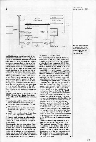
5
11+11M1. 1:1I11
SYMMSCRS CONTRO,SR DISPLAY ENABLE
CURSORMAR MAO 0 RS
4111
card builds up an image because it is notexactly the same as is shown in figure 4a.Figure 9b is somewhat different and showswhat space the 80 x 24 characters occupyin the total memory field of the card. Theactual written part is at the start, while allthe empty space is to the right and to theend. However, we want empty margins allround the edges of the screen and this isachieved by stating in the memory fieldwhere the horizontal and vertical synchron-ization pulses should occur. This meansin fact that the very bottom part of theaddress range actually appears et the topof the screen because the monitor startswriting from the top of the screen againafter the raster synchronization pulse.Thesame is true of the margins et the leftand tight of the screen but in this casethey depend on the line synchronizationpulse.All the 'digital traffic' is controlled by theCRTC (Cathode Ray Tube Connoller)on the video card. This IC has the followingtasks: locating the address of the character
which mum be written on the screen converting that character into the rele-
vant dot matrix. producing the horizontal and vertical
synchronization pulses at the righttimes
sending the matrix points of one lineto the video input of the monitor.
Horizontal and vertical synchronizationpulses can also be combined, as in theElektor VDU card, to form a 'compositevideo' signal.The controller also has some other func-tions such as choosing the desired pointmatrix, the number of characters per lineand the number of lines per image, thechoice of interlaced or non -interlacedimage and so on. It also drives the cursorwhich is visible on the screen and controlsthe connection for a light pen, which is
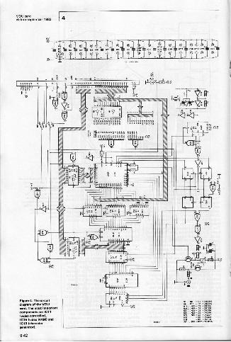
an 'option' on the VDU card.The block diagram of figure 5 shows themain parts of the VDU card. Apart fromthe multi -function CRTC it also containsa video RAM coda character ROM. Thevideo RAM stores all the characters whichmust be written on the screen. If 80 x 24characters must be written on the screenthen 1920 (= 80 x 24) memory locationsare needed so a 2 K RAM is used. The ROMcontains information on the dot buildupof each characMr, including the graphicssymbols. The CRTC controls communi-cation between the video card and the restof the computer system via the address anddata buses (they are actually combined toform the system bus). Data that mustappear on the screen is read by the control-ler and then placed in the appropriatememory location in the video RAM. Toread out the data in the RAM the CRTCruns through the whole address range of thememory so that the 80 characters of a lineare read out one after another. The datanow goes to the character ROM and here thedot pattern for these characters is located.Referring back to figure 3 we see that acharacter is written on eight lines. In thecase of the Elektor VDU card each seriesof 80 characters is read out 8 times, andeach time the dot pattern fora single imageline is read. All the dots for this line thengo to a shift register and they are thenoutput in serial form. When this is combinedwith the synchronization signal providedby the CRTC the result is a complete videosignal.This article was merely intended to be abrief description of the operation of aVDU card and monitor. We have referredin particular to the Elektor VDU card aspublished in this issue but most othersystems operate in much the same Way.However we hope that any quesrions aboutthis subject have now been cleared up,so now you know what to expect whenyou build your own!
Fipure 5. Block dievramof the VOU card. T.most important perts erethe controller ICRTC4Me video RAM and thecharectev ROM.
9-21
elektor septemiser 1993
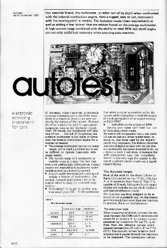
aelectronicservicing
for cars
Our essential friend, the multimeter, is rather out of its depth when confrontedwith the internal combustion engine. Here a rugged, easy to use, instrumentwith 'no moving parts' is needed. The Autotest meets these requirements aswell as adding a few 'extras' that are seldom found on the average multimeter.A high -current range combined with the ability to read RPM and dwell anglesare not only useful but necessary when servicing auto electrics.
Of necessity, today's motorist is extremelyeconomy conscious and is therefore morelikely to attempt car repairs that were pre-viously the domain of the 'expert'. However,this often leads to the need for specializedequipment, men in the 'electrical' depart.ment. Of course, our multimeter will takecare of this... but will it? In practice, theordinary multimeter is not really at homewith the intemal combustion engine for anumber of reasons. The average multimeter has far too many
ranges, not in itself a problem but it canbe difficult to operate (especially with
handsgreasy ). The current range of a multimeter in.
variably stops at 1 amp. The fact thateven car parking light draws almost 2 ampsrenders our sophisticated multimeter tetheruseless as soon as a bonnet is opened. A good usable lowoesistance range is not
usually a feature of multimeters. Thenormal, cramped scale leaves a lot to bedesired when looking for corroded bulbholders.
Robusticity! Or to put it another way,how would your E50 - E100 multimeter
Table 1
Tne Autotest ranges
rnmimum race.
current
voltage
20
20V900
resolution
10 and
10mV1013 mV
0.1 SI10010 RPM
0.1°
resistance
RPM
alma
MO ft20 Ica
7000 1391.1
90°
fare when propped somewhere under thebonnet while attempting to mad the outputof a voltage regulator of an engine runningat 3000 RPM?
... and while on the subject of RPM ...but no, your meter can't read that, can
it! How about dwell angles ...By now it win be apparent that a test meterfor use on cars is a rather special beast, somuch so, that those used by the !mums'can be very expensive. The Elektor Autotesthas been designed to take over the job thatour multimeter was never intended to do. Asa glance at table I will show, it manages thiswith comparative ease. The tobusticityfactor' is also very high due mainly to theUN of a printed circuit board and a liquidcrystal display.
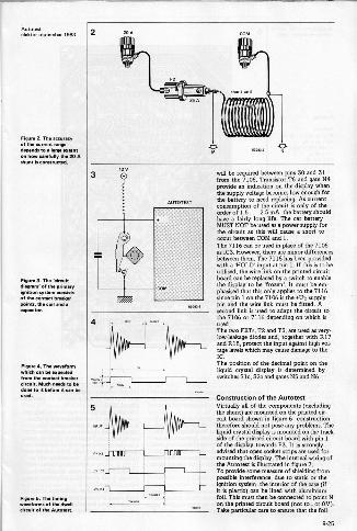
The Autotest rangesMost of the work in the circuit (shown infigure 1) is carried out by a 7106, a 31/2 digitA to D converter from Intersil. This IC iscapable of directly driving the liquid crystaldisplay and includes its own clock oscillatorand internal reference source.The Autotest has been designed to be assupple to use as possible and, for this reason,some tenninals have mom than one function.In practice, this is an ideal situation.
The resistance rangeWhen measuring resistance, connect the testleads between the COM and R terminals andswitch Si to position A. A constant current,generated by transirtort T4 and T5, b de-rived from the reference voltage whichappears between pins 32 and 1 of the 7106(IC3). The constant current is fed to the Rterminal and is passed through the resistanceto be measured. The consequent voltage
9-22
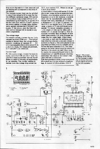
drop across the resistor is then measured andthe reading will correspond to the value ofthe resistor.The constant -current level can be switchedto one of two values by 52 to cater for thetwo different resistance ranges. With switch52 in position A the current will be 10 µA(determined by R20 and 1,1), in position B itwill be 1 mA (R21 and 1.5). Fuse Fl protectsthe circuit against a voltage being inadver-tently applied between the COM and R ter-minals. If this occubs, only the fuse willblow and no damage will be caused to anyother components.
The voltage rangeTo measure voltage, connect the test leadsbetween terminals COM and 0. The voltagereadings derived from the voltage dividernetwork consisting of resistors R1 ...05(R31 has negligible effect) with switch Si inposition B. Again, two ranges are provided,20 V and 200 V, by switch 52.
Current rangeFor the current range, connect the leads be-tween terminals COM and 20 A. Only theone 20 A range is provided: this will be suf-ficient to cater for virtually all applicationsin car entries. The current reading isderived from the voltage drop across the
20 A shunt resistor F(31. Where do we geta 20 A shunt from?A shunt resistor which will handle 20 A forthe current range can be an expensive item.However, since extreme accuracy is not soimportant to us in this instance, a suitableshunt can be manufactured quite easily.Copper wire with a diameter of 1.5 mm hasa resistance of 1.0112 per 100 metres. Forthe 0.0 1 12 we require for a 20 A currentrange, a length of 99 ems will therefore beneeded. To ensure complete accuracy a1.2m length of wire can be taken and acurrent of 1 A passed through it. With anaccurate voltmeter find the length of wirewhich gives exactly 0.01 volts dropped be.tween the two meter leads. Allow about1 cm more at each end for soldering andthen wind the wire into a nil and connect itas shown in figure 2. The coil diameter is notimportant provided it is of a suitable sizetofit into the space allocated to it. The leadsgoing to the meter circuit must be connecteddirectly to the shunt coil itself (there mustbe exactly the measured length between theconnecrions to N and M) because otherwiseinaccuracy will remit as the contact regntonce will also be measured.This then provides us with a very economical20 A shunt but it is not without a disadvan-tage. A current of 20 A across a 0.0112
III1111111111111111111111111111111111111
11!1!11.1!1!)1.11.11111.11.11l1!1111lITTINII:
elektorewptember l9®
Fissure 1. The relatvesimplicity of the circuit1:r Is: Amore. is mainly
..by the A/0 coyro nvener,
9-23
:lell=eptember 1983'resistor' will produce a power dissipation ofthe order of about 4 watts. The shunt coilwill then be the equivalent of a 4 W electricfire! The temperature rise itself is not somuch of a problem if adequate ventilation isprovided but, as the shunt warms up, itsresistance will increase. This is definitely nota desirable feature, even on a very cold day!Unfortunately, there is no real answer to thisproblem without the expense that we aretwine to avoid. However, if readings aretaken as quickly as possible (in about two orthree seconds for example), a reasonableaccuracy can be expected. Of course, lowercurrent readings will be less affected. It isworth noting that resistance wire could beused in place of copper wire although it isquite expensive and not very freely available.However its temperature coefficient is aboutfifty times better! The length will of coursehave to be recalculated.It is not advisable to reduce the length of theshunt coil in en attempt to increase the cur-rent range of the Autotest. The temperaturerise will be significantly faster and it will bevery difficult to achieve an accurate currentreading.
RPM measurementThe contact breaker points in the ignitionsystem of the car are the source of the signalused for RPM measurements in the Autotest.The circuit is connected to the car as shownin figure 3. The COM lead can of course beconnected anywhere on the chassis of thecar.Figure 4 shows the waveform produced bythe cb points. When the cb points open, apositive pulse is passed to the input of theAutoten and, via R7... T1 , triggers themonostable multivibrator (IC2). The outputof this IC will be a square wave with aconstant pulse width of 3.9 ms. The pulsefrequency will be that of the cb pointsopening. This waveform is integrated withthe result that the charge level on capacitor
C4 will be directly proportional to the fre-quency of operation of the cb points, andtherefore, the engine speed. The voltagearrow C4 is read and displayed as RPM.Preset PI is included for calibration purposesand will be discussed later.A distinct advantage of this principle is thatthe configuration of the engine (4 or 6cylinder) under test is of little concem. Thecircuit can cater for all types by selectingthe value of R13 and calibrating PI (see!Calibration!).
Dwell angle measurementAt this point, it may be as well to clarifyexactly what 'dwell angle' is. It is commonknowledge that the firing of the spark plugsin an internal combustion engine is con.trolled by the contact breaker points in theignition system. For maximum efficiency,it is important not only that the cb pointsopen at the correct instant, but also thatthey are closed for the correct period oftime. This is determined by the cb camprofile and - accurate setting of the cbpoints! In exact terms, the dwell angle is theangle through which the contact breakercam rotates while the points are closed. Itwill be obvious then that the dwell anglewill alter if the cb points are either badlyset or worn. Thus the dwell range of theAutoMst will be able to tell a few tales onthe condition of the cb points!The circuit for the dwell range shams thesame Input terminal (and most of the com-ponents) with the RPM range. However,there is an added problem with the signalwaveform from the cb points. In contrastto the RPM range, we need to know whenthe points close in order to derive the dwellangle. Therefore the cb waveform must bedebounced and inverted.After being voltage -limited by R6 and Dl,the cb signal is inverted by gates N1 ... N3,while for debouncing the circuit for theRPM range is used. The function of thedwell circuit is better explained by the useof the timing waveforms of figure 5. Theupper waveform is the signal which can beexpected from the cb points, complete with'ringing'. The second wavefomi shows thatthe overshoot has been removed (by Dl,NI and N2) by the time the signal reachesthe output of gate N2. The 7555 monostable(IC2) is triggered on the positive going edgeand provides a clean square -wave outputwith a puha width of 3.9 ms. This is thencombined with the output of N2 to producea final, debounced, inverted signal at theoutput of N3.After integration, the voltage across ca.pacitor C5 will correspond to the dwellangle. This is then read by the 7106 and,when calibrated by P2, provides a directreading of the dwell angle. A voltage level of50 mV at the wiper of P2 will produce areading of 50.0 (degrees).
The A/D converter and displayA few points of note about the 7106 A/Dconverter. For fullecale indication on thedisplay, an input voltage level of 200 mV
9-24
Autotestelektor september 1983
Figure 2. The accuracyof the current rangeepends. a large extent
on how carefully the 20 Ashunt is constructed.
Figure 3. The'diagram' of the primer,'ignition system c.sntsof the contact breaker!mints, the coil and acapacitor.
Figure P. The waveformwhich can be expectedfrom the contact breakercircuit. Much needs to bedope to it before stun beused.
Figure 6. The timingwaveforms of the dwellcircuit of the Antonin
2
will be required between pins 30 and 31from the 7106. Transistor T6 and gate N4provide an indication on the display whenthe supply voltage becomes low enough forthe battery to need replacing. As currentconsumption of the circuit is only of theorder of 1.5... 2.5 mA, the battery shouldhave a fairly long life. The car batteryMUST NOT be used as a power supply forthe circuit as this will cause a short tooccur between COM and 1.The 7116 can be used in place of the 7106as IC3. However, there are minor differencesbetween them. The 7116 has been providedwith a 'HOLD' input at pin 1. If this is to beutilised, the wire link on the printed circuitboard can be replaced by a switch to enablethe display to be 'frozen'. It must be em-phasised that this only applies to the 7116since pin 1 on the 7106 is the +Up supplypin and the wire link must be fitted. Asecond link is used to adapt the circuit tothe 7106 or 7116 depending on which isused.The two FETs, T2 and T3, are used as very -low -leakage diodes and, together with R17and R18, protect the input against high vol-tage levels which may cause damage to theIC.The position of the decimal point on theliquid crystal display is determined byswitches Sic, S2c and gates N5 and N6.
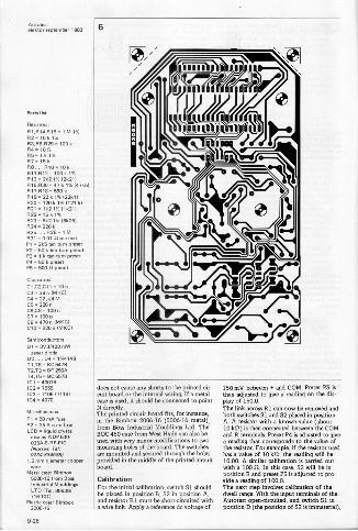
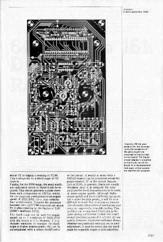
Construction of the AutotestVirtually all of the components (excludingthe shunt) are mounted on the printed cir-cuit board shown in figure 6: constructiontherefore should not pose any problems. Theliquid crystal display is mounted on the trackside of the printed circuit board with pin 1of the display towards P3. It is stronglyadvised that open socket strips are used formounting the display. The internal wiring ofthe Autotest is illustrated in figure 7.To provide some measure of shielding frompossible interference, due to static or theignition system, the interior of the case (ifit is plastic) can be lined with aluminiumfoil. This must then be connected to point Non the printed circuit board (not tad. or OV).Take particular care to ensure that the foil
9-25
A1010,september 1983 6
P arts list
Resistors:1:11,.14,R15= 1 kl1:12.10 k.3,.6,.29 -1001(.4 -10 11
R5-11(1%887-151(..
..10 -10 k.11..12=100 k 1%.I3T 2k2 1% (2k21)
/17k'1% 1471(5)O 17,-12i== 22 k 1%122k11
%2611(12.: 11:k2IskIi:11(612211
RN: ;11g 18k251
.25... R28 -1 M
.31 0.01 flax textPI 2k5 ten tum premtP2 50 ktentum presetP3
- I k ten rumP4 = 50 k preset57 S00 Preset
Capacitors:C, ,C2,C11 10n
3=39 n MCICOC4= 22 6/4 V
CS 220 n06.,08-100C7C9 =470 n (Wel010 - 220 n MARC)
SeiMconcluctors:01 = 363/400 rnW
senor diodeD2... 04 -164148
T1,T6 - BC 5476T2,T3 - BF 256A1-4,T5 = BC 5578.1 =400113102 75,5103-7106171161
.70MismIlaneous:Fl - 50 mA fuseF2 25 A auto fuseLCD= liquid crystal
isplay NOP 530.035AO..F.PIC(Norsern Tel:0734.8865881
1.5 mm diameter copperwire
Metal case: Bimbox5006-16 from BossIndustrial MouldingsLTD (Tel. 80638/716101)
Plastic case: 13' "s--ks,k2006.ts
does not cause any s rliromVom between .. and COM. Preset Pocult
birooardr000rmthLietehmort.s.. the printedoR,MoRdoci,irt-
Play O'Pl50.0to
9" ' r""4 onthe
Ills-
ovoed endiT'ohdemithedperiBnteimYprinted corm'.it'bidoesdh.":nts7fo'dr instance,eta1
The link acre. 1
Iboth switches S1 andca'S2ne'p7acbeedreinthBoss. 2006.16 with a known value P eith'e
and
(about(5006-16 metal A.kill)A is then
AOC 450 caIndustrial Mouldings
Lad .
reading that
connectedterminals.Preset P4
aammtehoe1COM
switchesQuotingwith very minor
modifyc..,ett also be
hasthe a valueresistor. of 101St,
example,, th e fft0hereadingthree d'el'ur:uogs.fle
with1id0.00ao.r.Aiado
calibration isuc.ar.iwo: m"utnomermoo'dmonoo-nrml:thimoase.thHerleat;ifou.eToh-
boat&mid'''. a the Mint h°"
CalibrationFor the initMlcalih ' The next '9 a 1C.", ' Pr'mbeoprlaledroin positionpositiothntf,nS2ewiintdechvehuoidf
Apply a reference dowith otest oponoirou
terminals of th
e wire link.r01 must he short-circuited
A,
Position D Oh"d' 'd witch SI in'AdP:inertilRera.IWPeibnt-ph-o.t:::::::::oeli;b:ra:tioi,willinrWof
the-
mheeterial),
9-26
'ettirrleptember 1983
adjust P2 to display a reading of 90.00.This corresponds to a dwell angle of 90degrees.Finally, for the RPM range, the small auxili-ary calibration circuit of figure R will be re-quired. This circuit generates a pulse wave-form with a frequency of 100 Ha, which,for our purposes, corresponds to an enginespeed of 3000 RPM fora four cylinderfour stroke engine. Connect the generatorbetween the + and COM terminals and adjustPI to give a reading on the display of 3.00(RPM = reading x 1000).The dwell range can be used for enginespeeds up to a maximum of 3000 RPMwith the circuit as it is. However, if it isthought necessary to measure the dwellangle at higher engine speeds, this can beaccomplished with a minor modification
to the circuit. A switch in series with a100 kit resistor can be connected across thepoints marked 'X' in the circuit diagram(left of R10). In practice, this is not usuallynecessary since it is adequate for mostpurposes for dwell measurements to be madeat lower engine speeds. Although higherengine speeds will show a defective spring onthe contact breaker points, it vrill be verydifficult to reach firm conclusions becausethe automatic advancerreMrd mechanism maycause an, apparently, unstable reading. Thisproblem can be aggravated by faults in thevalve timing, carburettor or even the closedcircuit breathing system if it is fitted. At lowspeeds, however, experience will soon ihownwhether the points are correctly set or needadjustment. It must be noted that the dveellangle fora specific engine is determined by
Figure 8. PP he com-he Auto(wieMeeaptan of
the 20 A shunt) aremounted on Me prinMdcircuit board. The liquidcrystal display is mountedon the track side of theboard. It is recommended.et open intine socketsare used for thk purpose.
9-27
AutotestelektOr apt Mr 1983 7
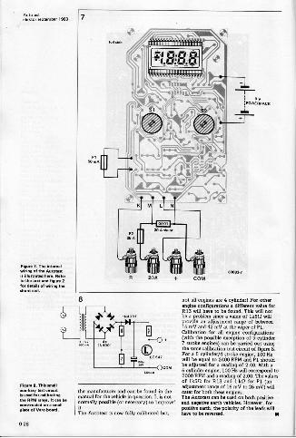
Figure 7. The internalwiring of the Autotestis illus.+. ere. Referto the OM and figure 2for details of wiring theshunt coil.
Figure 8. This smelleuxiliery test circuitis used for eelihnitingqe RPM ranee. It can beconstructed on a small
phew of Vero board.
se
1**
1111111111111111111111111111111111 f l 111
ttaiaet11111111711111111111111111111111111111
204 + COM
the manufacturer and can be found in themanual for the vehicle in question. It is not
it.possible (or necessary) to' mgreve'
it.The Autotest is now fully calibrated but,
not all engines are 4 cylinder! For otherengine configurations a different value for013 will have to be found. This will notbe a problem since a value of ass/ willprovide an adjustment range of between16 my and 42 mV at the wiper of Pl.Calibration for all engine configurations(with the possible exception of 9 cylinder7 stroke engines) can be carried out usingthe same calibration test circuit of figure 8.Fora 5 cylinder/4 stroke engine, 100 Hawill be equal to 2400 RPM and PI shouldbe adjusted fora reading of 2.40. With a6 cylinder engine, 100 Hs will correspond to2000 RPM and a reading of /00. The valuesof 1k5f2 for 013 and I kI2 for PI (anadjustment range of 16 my to 26 mV) willcater for both these engines.The Autotest can be uted on both positiveand negative earth vehicles. However, forpositive earth, the polarity of the leads willhave to be reversed.
9-28
66 k on the . k DynamicRAM card
elektor september 1983
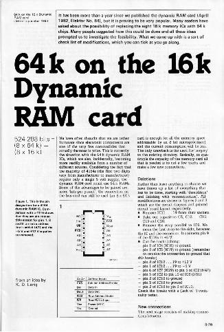
It has been more than a year since we published the dynamic RAM card (April1982, Elektor No. 641, but it is proving to be very popular. Many readers haveasked about the possibility of replacing the eight 16 k memory ICs with 64 kchips. Many people suggested how this could be done and all these ideasprompted us to investigate the feasibility. What we came up with is a sort ofcheck list of modifications, which you can tick as you go along.
64k on the 16kDynamicRAM card524 288 bits =(8 x 64 k) -(8 x 16 k)
Figure 1. This is the pindesignation for a 6168dYnsrmie RAM IC. Com-parison with a 8110 showsthat they are pin coMMI-tible except for pins 1, 8and : an mom addrersline is added IATI ma the-5 V and .12 V suppliesare removed.
from an idea byK. D. Lorig
We have often thought that we are ratherfortunate since electronic components amone of the very few commodities thatactually decrease in price. This is currentlythe situation with the 64 k dynamic RAMICs, which am also, incidentally, becomingmore rea.dlly available from a number ofdifferent sources. Considering the fact thatthe majority of 4164s (the first two digitsvary from manufacturer to manufacturer)require only a single 5 volt supply, thedynamic RAM card could use 64 k RAMS.Some of the advantages to be gained are,mom 'bits pm pound', the connectors onthe bus card can still be used (an 8 x 64 k
NC
we
tiltAO
AS
Vec
CTS
Dout
AS
AS
AS
Address Inputs
Column Address Strobe
Data In
Row Address Strobe
awl/WSW Input
card is enough for all the memory spaceaddressable by an 8 bit microprocessor)and the current consumption will be less.The only drawback is the need for 'surgery'to the existing circuitry. Basically, to qua-druple the capacity of the memory card allthat is needed is to cut a few tracks andmake a few new connections.
DeletionsRather than leave anything to chance wehave drawn up a list of everything thathas to be done, starting with 'demolition'and finishing with 'reconstruction'. Allmodifications are shown in figures 2 and 3which are the circuit diagram and printedcircuit board layout respectively. Remove IC11 ... 19 from their sockets. Take out capacitors C3, cll... C15,
C19 and C20. Remove the strap parallel to IC9. We
mean the first strap to the right, betweenthe IC and the connector. It connects pin 9of the 4116s to +5 V. Cut the tracks joining:- pin 2 of IC4 (918) to ground- pin 2 of IC5 (N19) to ground (remember
to remake the connection to ground thatthis breaks)- pin 8 of IC12 ... 19 to +12 V- pin 1 of 1C12 ... 19 to -5 V- pin 6 of IC7 (N29) to pin 5 of IC2 (1447)- pin 5 of IC2 to pin 10 of IC8 (N31)- pin 2 of IC10 to ground- pin 3 of IC10 to ground- pin 2 of 1C10 to pin 3 of IC10.Check the breaks with a (lack of !) conti-nuity tester.
New connectionsThe next stage consists of making connec-tions between
9.29
64 k on Me 16 k DynamicRAM cardelektor mptember 1993
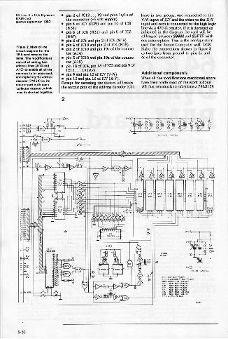
Figure 2. Mon of thecircuit diagram for Me16 k card remains thesame. The modificationsconsist hoesg Iwoaddress 1A14 andA16/ to enable all of thememory to be addressed,
and replacin1741g the addressdecoder 541 by itscounterpart with opencollector outputs, whichmay be shamed together
pin 8 of IC12 ... 19 and pins 1a/10 ofthe connector (+5 volt supply)pin 6 of IC7 (N29) and pin 10 of IC8(N31)pin 8 of IC8 (N31) and pin 5 of 1C2(N47)
pin 8 of IC6 and pin 2 of 105 (1,119) pin 4 of ICIO and pin 2 of IC4 (N18) pin 2 of IC10 and pin 19c of the connec-
tor (A14) pin 3 of 1C10 and pin 19a of the connec-
tor(A15) pin 18 of 1C4, pin 18 of 105 and pin 9 of
IC12 ... 19(A7)pin 9 and pin 10 of IC7 (V.W)pin 12 and pin 13 of IC7 (X -Y).
Except for decoding the desired addressesthe output pins of the address decoder IC11
leave in two groups, one connected to theV/W input of 1C7 and the other to the X/Yinput and each is connected to the high logicline via a 470 ft resistor. If it is decoded asindicated in the diagram the card will beaddressed between 30000 and SBEFF with-out interniption. This W the configurationused for the Junior Computer with DOS.Make the connections shown in figure 3as two lines from ground to pins 9a and4c of the connector.
Additional componentsWhen all the modifications mentioned abovehave been made most of the work is done.AU that remains is to substitute a 74L5159
2
"°.1I *V t," ;*
% !AO/ /
r),
L
9-30
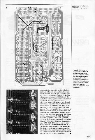
(open collector outputs) for the 7415154(IC11). If it has not already been done Clcan be replaced by an 80 pF variable capaci-tor. This is to enable the timing relationshipbetween the triggering of MMV1 and thestart of the refresh pulse to be set to preventthe refresh from occurring too soon.It is a good idea at this stage to rtm througheverything done an far just to check that allis as it should be. Then the last thing to dois to inert all the new memory ICs in theirsockets. They are available from a nnmbenofdifferent manufacturers, most of whom areJapanese, and have different 'names', exceptthat the last two digits are always '64. Somepossible examples am F4164 (Fairchild),MB8264 (Fujitsu), HM4864 (Hitachi),ITT 4164, MSK 4164 (Mitsubishi), MK 4564(Mostek), NMC 4164 (National Semiconduc-tor), UPD 4164 CID and so on... thechoice is yours. In the article on the 16 kDRAM card the principle of the refresh wasdescribed in detail and a program was givenfor checking the memory, so as a final checkiris worthwhile to run this program to checkthe 524 288 bits of your 'new' cani. N
16 k Dyne..
Mak.. september 1983
Figure 3. This layout ofthe printed circuit hoardclearly shows the tracksthat have to be cut and thenew connections Mat areto be made. Note thatsome wound lines are toonarrow for this applicationand therefore need to bereinforced. And don't...pet to remove the strapbeside 189.
9-31

amhto°a.meme.r tees
new high-speedCMOS logic
LSTTL speedwithCMOS currentconsumption
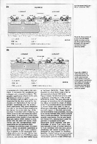
Fiure 1. Cross...ion ofg
a chip manufactured isTthe inefelpete.CMOSProcess. The parasiticcapeeitanoss which havebeen drawn in preventfaster switching.
Speed is not magic, but it has its price: fast logic circuits use more current. TTLtechnology is fast and greedy, CMOS on the other hand is slow and economical.But now, advances in CMOS technology are making it possible to combine TTLspeed with CMOS economy. A new family of logic circuits, high-speed CMOS,combines the speed of LSTTL with the advantages of CMOS and looks setto become the standard and eventually replace both the CMOS and TTLtechnologies.
The present situationBipolar digiml ICs have been around forsome fifteen years. This first, and fora longtime only, technology for logic elements isstill the fastest and, through TTL and ECL,also the most successful. Its big drawbackremains the power dissipation.CMOS technology, on the other hand, offerslow current consumption, a wide range ofsupply voltages, and high immunity to inputnoise. Its drawback is the lack of speed.During the past few years CMOS has becomesomewhat faster, and TTL, through the LSversion, a little less power -greedy. None theless, the two technologies are still separated
by a wide gulf. At present, it would appearthat CMOS just about offers the bestcompromise between speed and powerdissipationHigh-speed CMOS combines the speed ofLSTTL with the advantages of CMOS. Theyoungest member of the TTL family, theALS version, is faster than LS and has onlyhalf its current consumption.
How CMOS has become fasterStandard CMOS and the majority ofbuffered CMOS-ICs are manufactured bythe metal -gate process. Figure 1 shows a
932
2a HE 40000
n.channel
roSs EThP.so,
LOCOS - local omtlation of mimeo,
ocbannel
saotasaa
2b
P.,.USiU Si02
alum kn rn
HC MOS
n+
p.thellnel
dram gate mu
82078.21a
crow -section of a chip made in this tech-nique: it represents the complementaryn -channel and p.chermel transistors. Theparasitic capacitances between drain, gate,and source are added for clarity.The switching speed of a MOS transistor isdetermined by the thne required for thecharging and discharging of the internalparasitic capacitances and the external(load) capacitance. This tine is dependentnot only on the value of these capacitancesbut also on the current gain, hfe, of thetransistor. A tnnsistor with a higher hfe candeliver more current and charge the capaci-tances faster. A consequence of the morai-nela process is that transistors have relativelylarge gate regions which overlap to someextent with the drain and source. Smallcurrent gain and correspondingly largecapacitances are the inevitable result.To increase the switching speed, it is neces-sary to reduce the parasitic capacitance aswell as to raise the gain of the transistor.This is achieved in the silicon -gate tech-nology which since the mid '70s has beenused in the production of CMOS-processors,memories, and also the HEF 40000 family
of buffered CMOS-ICs. Them CMOSelements are about three times as fart asthe standard metal -gate 4000 series.Figure 2 shows the structure clan n- anda p -channel transistor on a chip of theHEF 400013 family. The gate electrode isno longer of aluminium, but of polycrystal-line silicon embedded in a layer of siliconoxide. Polycrystalline silicon can be etchedin thinner layers than metal so that insilicon -gate technology the position of thegate with respect to the drain and sourcecm be established more acmrately, resultingin an overlap between them which is smallerthan in metel.gate devices. This reduces theparasitic capacitances. Shorter gate lengthand thinner SiOt isolating layers under thegate lead to increased current gain.Silicone. CMOS originally used gatethicknesses of about 6 pm which werelater reduced to 4 gm. A further reductionto 3 pm combined with even more precisepositioning and thinner isolating layersproduced an improvement in switchingspeed by a factor 5 and an increase in outputcurrent by a 000101 10. This completed thetechnological quest for a new CMOS-logic
Figure 2a. Cross-section ofa chip in the HE 400021family manufactured bythe sili.n.te technique.Reduced internal capaci-tances allow higherswit.ing speeds.
Figure 2b. HOMO. isalso produc. Sc Its:iliconqateenzmas..r.lts
canl"srtgul'her c'elmionin the internal capacitancesa. higher current gain ofthe transistors. HCMOSMeteors providm higheroMput currents. higher
Peed
9-33
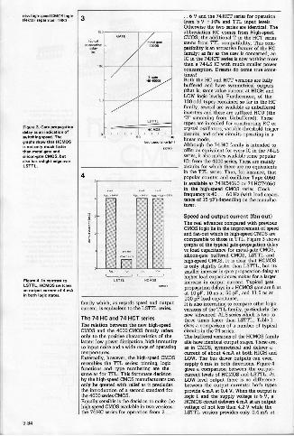
Figure 3. Gate.propagationdelay as an cation ofswitching peed. Thegraphs show Mat HCMOSis not only much fasterthan mMalwate endsilicomgere CMOS, butalso hes a slight edge overLSTTL.
Figure 0.1n contrast toLSTTL,NCMOS switchesan output current of 0 maiin both logic states.
3
iced mammas he,
4
5-5;5-M 5
family which, as regards speed and outputcurrent, is equivalent to the LSTTL series.
The 74 HC and 74 HCT seriesThe relation between the new high-speedCMOS and the 4000 CMOS family refersonly to the positive characteristics of thelatter: low power dissipation, high immunityto input noise and a wide range of operatingtemperatures.Extemally, however, the high-speed CMOSresembles the TTL series: pinning, logicfunctions and type numbering are thesame as for TTL. This fortunate decisionby the high-speed CMOS manufacturers canonly be greeted with relief as it precludesthe introduction of a second standard forthe 4000 series CMOS.Equally sensible is the decision to make thehigh-speed CMOS available in two versions:the 74HC series for operation from 2 ..
..6 V and the 74HCT series for operationfrom 5 V *10% and TTL input levels.Otherwise the two series are identical. Theabbreviation HC comes from High-speedCMOS; the additional Tin the HCT seriesstems from TTL compatibility. This com-patibility is an attractive feature of the HCfamily: as far as the user is concerned, anIC in the 74HCT series is now nothing morethan a 74 -LS IC with much smaller powerconsumption. Dreams do come tare some-times!Both the HC and HCT versions are fullybuffered and have symmetrical outputs(that is, same value current at HIGH andLOW logic levels). Furthermore, of the120 -odd types contained so far in the HCfamily, several are available as unbufferedinverters and these are suffixed HCU (the'U' stemming from Unbuffered). Thesetypes are intended for constructing RC orcrystal oscillators, variable -threshold triggercircuits, and other circuits operating in alinear mode.Although the 74 -HC family is intended tooffer an equivalent for every IC in the 74.LSseries, it also makes available some popularICs from the 4000 series. Them are mainlycircuits for which there are no equivalentsin the TTL series. Thus, for instance, thatpopular counter and oscillator Type 9060is available as 74 HC9060 or 74 HCT4060in the high-speed CMOS series. Clock.frequency is 90 ... 60 Hs (with load capaci-tance of 15 pF) depending on the manufac-turer.
Speed and output current (fan.out)The real advances compared with previousCMOS logic lie in the improvement of speedand fan -out which in high-speed CMOS arecomparable to dm. in TTL. Figure 3 showsgraphs of the typical gate -propagation delayvs load capacitance for metal -gate CMOS,silicon -gate buffered CMOS, LSTTL andhigh-speed CMOS. It is clear that HCMOSis only slightly faster than LSTTL, but itssmaller increase in gate -propagation delay athigher load capacitances makes fora largerincrease in output current. Typical gatepropagation delays in a HCMOS gate are 8 nsat 10 pF, 10 ns at 50 pF, and 11.5 ns at100 pF load capacitance.It is also interesting to compare other logicversions of the TTL family, particularly thenew 'advanced' ALS series which is two tothree times faster than LSTTL. Table 1gives a comparison of a number of typicalcircuits in the 74 series.The buffered versions of the HCMOS familyalle have identical output stages. These are,as in CMOS, symmetrical and deliver acurrent of about 4 mA at both HIGH andLOW. The bus driver outputs can evensupply 6 mA in both directions. Figure 4gives a comparison between the output -current levels of HCMOS and LSTTL. AtLOW level output there is no differencebetween the output currents: both typesprovide 4 mA at 0.4 V. When the output islogic 1 and the supply voltage is 5 V, aHCMOS circuit delivers 4 mA at an outputvoltage of not less than 9.2 V while theLSTTL version provides only 0.4 mA at
9-34
not less than 2.7 V.A standard HCMOS output can, therefore,like that of en LSTTL circuit, be connectedto up to 10 LSTTL inputs The farnoutwith bus driver output is 15 LSTTL loads.In the case of HCMOS loads, the inputcurrents (typically 1 µA) have practically noeffect, so that the fan -out is limited only bythe input capacitance (typically 5 pF) andnot by the drive power. One output can beconnected to up to 20 HCMOS inputswithout any noticeable deterioration. Ifspeed and signal.to-noise are not important,it is possible to connect up to 4000 inputsto one output. Only then, at least in theoryis an output current of 4 mA reached.
Current consumption. increase athigher switching frequenciesLower current consumption not onlyreduces operating costs, but because ofthe reduction in heat, it also improvesreliability. The quiescent current ofHCMOSis, like that of CMOS, negligibly small as, incontrast to TTL, the leakage current is ofthe order of only a few riA. During switching,however, internal and external capacitanceshave to be charged which means an increasein current. The higher the switching fre.quency, the higher the current consumption.In that respect, there is no differencebetween HCMOS and CMOS, butHCMOScircuits can =itch much faster and thereforehave a correspondingly higher power dissi-pation. The quiescent current hi TTLcircuits is already so high that adclitionalcurrent consumption becomes only notice-able at very high switching frequencies.Figure 5 shows this basic difference betweenHCMOS and LSTTL. If only one circuit isconsidered, as in the figure, the powerdissipation of HCMOS and LSTTL reachesthe same value at an operating frequencyof only a few MHz. A practical system,how nests of a much greater numberof IC, which in turn contain several el-ements such as gates, flip.flops, and the like.LSTTL circuits use the same current what-ever their operation; in HCMOS only thoseelements which actually switch consumepower. For instance, in a counter with10 flip-flops using LSTTL circuits, all flip-flops dissipate the same power, but ifHCMOS circuits were used, each flip-flopwould consume only half of what thepreceding one does. This fact tips thebalance firmly in favour of HCMOS, as isshown in figure 6. In a standard micro.computer system with e 2 MHz or 4 MHzCPU, HCMOS circuits would use only afraction of the power LSTTL devices do.Even in a system with a 10 MHz micro-processor, the power dissipation in HCMOScircuits would be only about one eighth ofthat if LSTTL devices were used.
Supply voltage, input level, andsignal-to-noise ratioThe supply voltage for the HC and HCUversions of the HCMOS family can varybetween 2 ... 6 V. The =tension of thelower voltage limit to 2 V is particularlyinteresting in view of future generations
of microprocessors and memories whichwill require a supply voltage of less than5 V. Non -stabilized power supplies andbatteries can be used without any problems,while one lithium cell or two nioad cellscan serve as emergency supply.The switching levels in HCMOS lie furtherapart than in LSTTL as can be seen clearlyfrom figure 7. That means on the one handa higher immunity to noise, but on theother that the inputs of HCMOS devicescannot be connected to the outputs ofTTL circuits if the supply voltage is 5 V.ICs in the HC version can, however, be
5
6
napeed CMOS lock
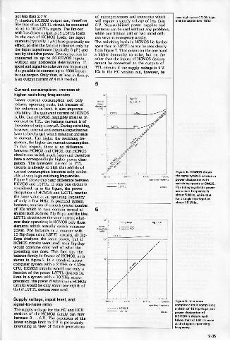
Figure 5. HCMOS showsOm mine tYP.1 increase inpower dissipation withswitching speeds es CMOS.For a single gate the powermosso,. frequency isabout 5 MHz while thinfor a single flip-flop lies8..10 MHz.
Figure 0.1n a moreoomph. circuit comprising
ohain of 10 flimflops, thePria. di...on ofHCMOS is dearly wellbelow that of LSTTL wenat the high. operating
9-35
==r1c."."°17°' 7
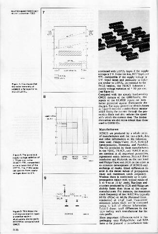
Figure 7. This shows thatthe noise immunity ofNCMOS is ler superior toMet of LSTTL.
Figure 21. The permit,.MPPiy volume variation of
14001 lllLoenrp.tibt.ltwice that of Me
LSTTL. The 7411C seriescan operate from woesvolumes down to 2 V.
Figure 9. This Mows thereal improvement in inputprotection imainstelectrostatic discharges inNCMOS ss Compared withCMOS.
if
/° itevt ...ere si9 v
ritoPSum,
8
9
combined with LSTTL types if the supplyvoltage is 3 V. None the less, OCT types areTTL compatible if the supply voltage is5 V. Input levels and immunity to noiseare similar to LSTTL. In contrast to the74 LS version, the 74 OCT tolerates asupply voltage variation of * 10 per cent(see figure 8).Compared with the already hard-wearingCMOS circuits of the 4000 family, theinputs of the HCMOS inputs are evenbetter protected against electrostatic diecharges. The input protection circuit shownin figure 9 contains a poly -silicon resistorwhich limits the current through the pro-tection diode and also reduces the speedwith which the current rises. The diodesthemselves are also more robust than thoseused in CMOS ICs.
ManufacturersHCMOS are produced by a whole seriesof manufacturers and, for this article, dataand other information of the followingwere used: PhilipsNalvo, RCA, NationalSemiconductor, Motorola, and Fairchild.The ICs produced by these manufacturersin the 74HC, 74 OCT. and 74 HCU seriesare identical in all important parameters.Agreement exists between National Semi.conductor and Motorola on the one handand PhilipsNalvo and RCA on the other asto common development of HCMOS andexchange of masks. Small differences doexist in the stated values of propagationdelay and maximum clock frequency.Whereas there is conformity as to gate -propagation delays with typical values of8 to 9 ns at 15 pF loads, flip-flops andcounters produced by RCA and Philips areslightly faster than those of the othermanufacturers. For instance, the maximumMock frequency of the 74 HC79 is typically60 He (RCA) or 40 Ha (National Semi-conductor) at 15 pF load. Guaranteedminimum sallies could not be comparedowing to lack of relevant information.Table 2 shows small differences in thetype coding: each manufacturer has hisown prefix.More important differences exist in thepackaging: only Philips/Valvo and RCAhave so far planned to manufacture their
9-38
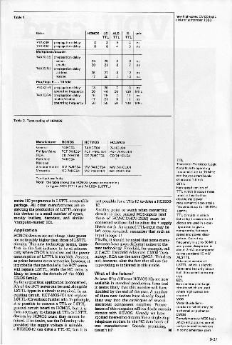
Table 1
OSM HCMOS LS. ALS. S. unitTTL TTL TTL
743300 Propagation de./743804 propagation delay
ns
Plehiplerter/decoder
74710139 Propagation May
7400151nacre
pr.odisdacon May20
2521 8
nsno
Strobe2617
2726
lz
tznsns
Plip/flom 5...18 fob7434174 propels... nee
°Penning frequency113
602040
7
5013
100ns
MHz7433374 propagation 41.61
enable/disable1617
1921
79
11 rens
oPerating haw., 50 50 50 100 MHz
3.4k14 2. TYPennehng of HCMOS
Manufacturer HCMOS HC711106 MUMSGeneral 74HCO4 74 HCTO4 741461104Phil ips/ValuoRCA
PCF 7411C04CD 7418604
PCF 74HCT04CO 74HCTO4
PCF 7411611047411CUO4
FairchildNational
7414604
SemiconductorMotorola
MM 4HCOOMC 74HCO4
MM 74HCTOOMC 74FI6704
MM AMC.).MC 74140004
not yet availableNote: the table P.m the FICM06 WPM .../PrekrEng
to types 7404 1TTLI and 74 LSO4 ILSTTLI
entire HC programme in LsTri.. compatiblepackage. All other manufacturers are re.shitting the production of LSTTL cornea.ible devices to a small number of type,mostly buffers, decoders, and similarcomputervelated' ICs.
ApplicationHCMOS devices are not cheap: their pricesare noticeably higher than those of LSTTLcircuits. This new technology seems, therefore, in the first instance to be of interestonly where CMOS is too slow and the powerconsumption of LSTTL is too high. As soonas prices become more attractive, however, itis probable that particularly the HCT serieswill replace LSTTL, while the HC series islikely to invade the domain of the 4000CMOS family.As far as practical application is concerned,ICs of the Hcr series can be used alongsideLSTTL types in a circuit as required. In anWining circuit, HCT-MOS-ICs can replaceLSTTL-ICs without further ado. In principle,it is possible to convert a TTL or LSTTLprinted circuit board to HCMOS, but it isthen necessary to change all TTL or LSTTLdevices by HCMOS ones: they cannot bemixed. If in doubt, use the following rule:provided the supply voltage is suitable,a HCMOS-IC can drive a TTL-IC, but it is
not possible fora 774IC to drive a HCMOS-IC.Another point to watch when convertingcircuits is that unused MOS.inputs (andthose of HC/HCT'ffICU.MOS) must beconnected without fail to either the supplyline or earth. An unused TTL-input may beleft open -circuited: remember that such aninput is logic 1!Finally, it should be noted that some menu.banters have given different names to thenew technology. Fairchild, for example, callit FACT: Fairchild Advanced CMOS Tech-nology. RCA use the name QMOS. This doesnot, however, alter the fact that all use thetype -coding as indicated in this article.
What of the future?At least fifty different HCMOS-ICs are nowavailable in standard production form andit seems likely that this number will havedoubled by the end of the year. A numberof these new devices have already foundtheir way into the catalogues of severalelectronic component suppliers. Futureissues of this magazine will no doubt containcircuits with HCMOS. Already we havespotted interesting circuits like a single -chiptelephone madam in the HC data book ofone manufacturer. Sounds promising,doesn't it?
:=:°=",11.7°'
TTLTrensistonTransistor Logic
circuits with operatingfrequencies t.. MHzand
input currant levelsof around 1.6 mASTTL.OhnOtlevi version ofTTL which is about .reetimes as fast but has
double the powerrequirern.t; it can attain
frequencies up to 100 MHzLSTTLTTL circuits in which
Schottky transistors anddiodes are used in a configuration to gin acompromise betweenspeed a. power dissi-
n. Operatingfrequency is up to 50 MHzand power dissipation is
2 mW as comperedboutto the standard 10 mWALSTTLAdvanced version ofLSTTL which is slightlyfaster and has only abouthalf the current consume.tionECLEminerCoupard Logiccircuits whi. are usedwher high Ram. arerequiredMOSMetal Oxide Semi -no: htinczrowhr pi,chzneny.,18.
CMOSComplementary MOS logicwhich employs nnhanneland pnhannel transistorsin complainer., pain
9.37
VDU cardelektor se3ternber 1983
video forcomputers
in conjunction withH. Vermeulen
VDU card
In Elektor we like to keep up to date, and we feel that the time has come fora new video card. The VDU card described here is not simply a modern receiverfor the old and still popular Elekterminal, rather it is a new design intended touse all the possibilities of a modern computer. It can display 24 lines of 80characters on the screen, graphics are available, and there are several otherpossibilities. Numerous Junior Computer users have long been waiting to beable to equip their computer system with its own video card. However, thiscard is intended not only for the Junior but also for other processors, such asthe 6800 family and the Z80.
The accompanying article in this issue'Video graphics' describes the principles of aVDU card and is good background materialfor anybody who is not totally familiar withthe subject, 3.3, rather than duplicate any ofthat here, we will simply describe the circuitfor the VDU card. At the same time, wemust explain what the further possibilitiesof this card are and this is where we willbegin.
VDU card ... and terminal?Here we will consider the VDU card as anindependent unit. In this form it can be
connected directly to the expansion bus ofthe Junior Computer. The only extra com-ponent needed is a 2716 EPROM with aVDU output program in place of the printermonitor program.Figure 1 shows the main components whichmake up the VDU. First is the actual VDUcard, with the Cathode Ray Tube Controller(6845), a 21( video RAM (6116), and thecharacter generator - the block diagram isshown in the descriptive article. The charac-ter generator consists of a 2732 EPROM inwhkh all the ASCII and graphics symbolsare gored in the appropriate dot-matrix
9-38
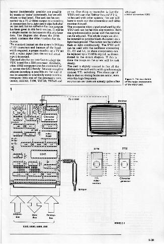
layout (incidentally, graphics are possibleby means of 'poke' commands, but we willreturn to that later). The card can be con.nected via a 75 it video output to a monitor.A connection for a
softwareen is also included
on the card but no for this purposehas been given in this basic version. It will bea simple matter to incorporate this at a laterdate. The diagram also shows the 2716which contains the video routines for theJunior.The standard format on the screen is 24 linesof 80 charmers and because of the band.width required, a proper monitor or a TV setwith a video input (not the normal aerialinput) is needed.The card also has an interface to adapt theVDU board for a Z80 processor. Similarly,other 6502 computers can be connected toit, as can the 6800 family. Because completeaddress decoding is possible on the card itcan be adapted to practically every moderncomputer with one of the processors men-tioned; AIM 65, SYM, VIC 20, VIC 64 and
so on. One thing to remember is that theVDU card uses the Elektor bus and if it isto be used with other systems, the user willhave to work out the connections and videoroutines himself.The composite video signal produced by theVDU card can be fed into any monitor. Boththe synchronization pulses and the contrastcan be adjusted. The whole image can alsobe inverted to provide black characters on alight background. The cursor can be made toflash or light continuously. The VDU cardcan be used with the oscillator containingCl, C2 and Ll, or these components canbe replaced by a 15 MHs crystal, as showndotted in the circuit diagram. If this isdone the image on the screen will be rocksteady.The card is slightly unusual in that all thetiming on the card works with synchronouslyclocked TTL switching. The advantage ofthis is that no timing faults can occur, evenwith this high frequency.As you can see there am already quite a few
Addresu Date- Control -Bus am a..
6602,6800,99119.2111
elelcto:VIstamber 1983
Figure 1. This Is a sketchof the major components
t the VDU card.
83082-2-1
939
VDU cardMaims septeteMM 190 2
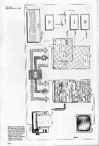
Figure 2. This shows whatun ultimately be achievedwish the universal terminalconMinum a VDU card anda CPU card. All Me otherequipment IcOmPum,modern, printer, key laurela. so on) can be con.named to this terminal
940
possibilities with the VDU card but there areeven more to come. Asa follow up to thisVDU card we will shortly publish a CPUcard especially developed to complement it.These two cards will together form the basisof a universal terminal with RS 232 interfaceand VT 52 protocol, so that it can be con-nected to virtually any computer. Figure 2shows the main parts of this system and ofcourse this terminal can be connected to anycomputer which has an RS 232 interface.The CPU card contains a 6502 micropro-cessor, 2 VIAs (Versatile Interface Adapter),an ACIA (Asynchronous CommunicationsInterface Adapter) an EPROM and a RAM.Thanks to a set of through connections onthe board the transfer format, speed, num-ber of start and stop bits and the type andnumber of control bits can be adapted towhatever computer is connected to theterminal. Similarly there is a choice of eightdifferent screen -image formats.All that is needed to make up a completeterminal is a VDU card, a CPU card, amonitor and a keyboard. The terminal could,for example, communicate over the tele-phone lines via a modem, with a computerin some other part of the globe, but becauseof its VT 52 protocol it could also be con.nacted directly to a 16 bit computer. Aconnection for a printer is, of course,provided. It is also possible to use the CPUcoed and VDU card together as the basis for
complete computer system, as figure 3shows. This example is connected to a 16
bitter but, in principle, that could be anytype of computer.The terminal software is located in a 2716EPROM on the CPU card winch can have amaxiinum of 8 K of random amen memoryand 161( of read only memory.Clearly there are already quite a few possi-bilities for this two -card combination andoncertainly there are more than we have me.
ed. However we will leave it at that untilthe article on the CPU card.
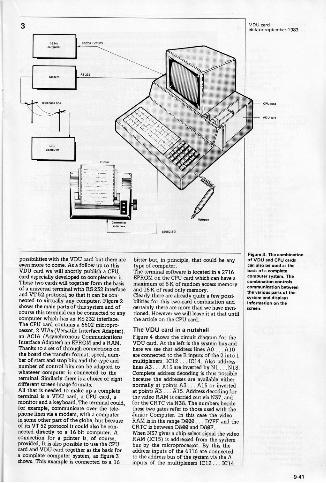
The VDU card in a nutshellFigure 4 Mows the circuit diagram for theVDU card. At the left is the system bus andhere we see that address lines AO... A10are connected to the B inputs of the 2 into 1multiplexers, IC12 ...1C14. Also addresslines A3 . . Al5 are inverted by N1 ... N13.Complete address decoding is thus possiblebecause the addresses are available eithernormally at points A3... A15 or invertedat points A3... A15. Address decoding forthe video RAM is carried out via N37, andfor the CRTC via N38. The numbers besidethese two gates refer to those used with theJunMr Computer. In this case the videoRAM is in the range D000 ... D7FF and theCRTC is between 2800 and D8OF.When N37 gives a chip -select signal the videoRAM (IC15) is addressed from the systembus by the microprocessor. By this theaddress inputs of the 6116 are connectedto the address bus of the system via the Ainputs of the multiplexers IC12 ... IC14
Figurecombinationof VDU and CPU cardscan also lae used as thebasis of a completecomputer SytteM. Thecombination controls
on betweenthe various parts of theSydeM and displaysin on the
941
4
(R R7
Eitifigt :ttiitit±L*
fi tnnTr,t_g!!.
942
5VDU nerdelektof Senternher 1983
:00000000000000000.0.00oomm.'00000000000000000000000
5144.5 boa'adaaa"
3r r Aar
4.)C-fi_i 1444
al_AO
411111.81t''' 4U.LA!
(select inputs of the multiplexers are logiczero). At the same time data bus buffer IC10is enabled via N14 and N24. The logic levelof the RAV line (pin 29c of the connector)ensures that IC15 le enabled via N32, N23and the WE input.It the CRTC is addressed from the systembus N38 gives a logic zero to the a input.The processor then has access to the internalregisters of the 6845 via the system bus.Data bus buffer IC16 is then aLso enabled viaN16 and N26.IC16 is really only needed of a light pen is tobe used with the VDU cartl. If this is not thecase, and data is only written from the busto the CRTC, then IC16 is superfluous andthe 6845 can be connected directly to thedata lines with eight wire links.Address decoder N37 resew flip-flopsFF1 ... FF4 so that no rubbish appears onthe screen when the processor accesses thevideo RAM.
The timing of the VDU card is controlled bythe oscillator based on N17 and N18. Thissupplies the so-called dot frequency, whichis 15 MHz for the screen format used here.A cod is necessary to maintain stability ofthe oscMator at this relatively high fre-quency. For optimum performance, a15 MHz crystal could be used in the owllator in place of Cl, C2 and LI. IC21 dividesthe oscillator signal by eight. This IC is asynchronous counter which is reset via N30when the count reaches seven. Because thereset is only processed by the IC on the fol.lowing clock pulse, the IC then effectivelycounts to eight. Output QC delivers thecharacter frequency for the controller. TheCRTC counts continuously from 000 to7FF (the whole range of the video RAM) atthe frequency of this signal. As the processornow has no access to the video RAM, theaddress outputs MAO ... MAIO of IC12 areconnected to the address inputs of the 6116
hob list
Resistors:R1,82 470 n
100 SIRS,R6R7R9,R10 - aka
Cepacitors:C1=40 p trimmerC2 10 p trimmerC3,C5 C19 100nC4=1 si/OV
Semiconductors:T1,T2 BS% 20CLIC, 7415240C3- 74.04CO= 74.00CS - .699CS - 74.10C7 - 761527CS= 76.30C9= 7.133C10,1C19 e 7415205C11 = REM012,1C13,IC14 - 76.167C15-6119C17 = 74.175C19=741-3273CIS = 2732Ca0= 74.100Cal = 7.6163
Miscellaneous:e 15 Moe crystel (for a
display configuration of80 a 20 characters: if thismy. used CI, C2 andLI are not nee..
LI -4.7 isle94 pin male connectorDIN use Men end C1.0145
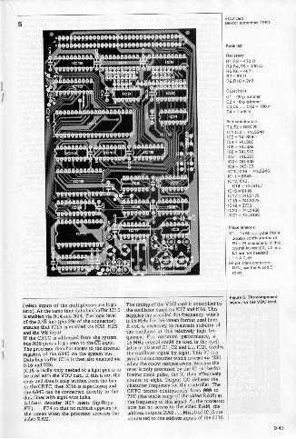
Figura 5. The coml...mleyout fort. VDU card.
943
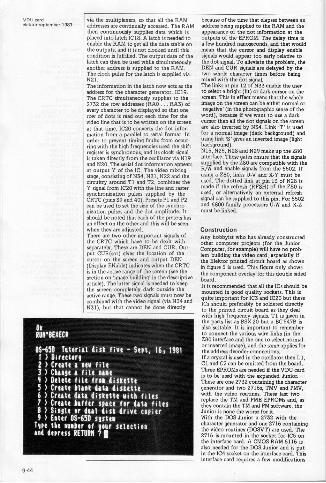
ele1:'::::',98mber 1983via the multiplexers, so that all the RAMaddresses are continually accessed. The RAMthen continuously supplies data which isplaced into latch IC18. A latch is needed toenable the RAM to get all the data stable onthe outputs, and it is not clocked until thiscondition is fulfilled. The output data of thelatch can then be used while simultaneouslyanother address is supplied to the RAM.The clock pulse for the latch is supplied viaN21.The information in the latch now acts as theaddress for the character generator, IC19.The CRTC simultaneously supplies to the2732 the row addresses (RAO . RA3) ofevery character to be displayed so that onerow of dots is read out each time for thevideo line that is to be written on the screenat that time. IC20 converts the dot infor-mation from a parallel to serial format. Inorder to prevent timing faults from occur.ring with the high frequencies used the shiftregister H synchronous, and its clock signalis taken directly from the oscillator via N19and N20. The serial dot information appearsat output Y of the IC. The video mixingstage, consisting of N34, N31, N22 and thecircuitry around TI and T2, combines theY signal from IC20 with the line and rastersynchronization pulses supplied by theCRTC (pins 39 and 40). Presets PI and P2can be used to set the size of the synchro-nization pulses and the dot amplitude. Itshould be noted that each of the presets hasan effect on the other and this will be seenwhen they are adjusted.There are two other important signals ofthe CRTC whack have to be dealt withseparately. These are DEN and CUR. Out-put CUR(sor) gives the location of thecursor on the screen and output DEN(Display ENable) indicates when the CRTCis in the active range of the screen (see thesection on 'image building' in the descriptivearticle). The latter signal is needed to keepthe screen completely dark outside theactive range. These two signals must now becombined with the video signal (via N34 andN31), but that cannot be done directly
Ot
RUll'BEXECI
05-650 Tutorial disk five - Sept, 16, 19811 ) Directorg
2 ) Crate e AtA file3) Cheep e file tilt4) Delete file trot diskette5 > Create ilea date diskette6 > Orate date diskette with files7 ) Orate haffer site for deli files8) Single or duel disk drive copier9) Enter 05-650 sister
lope the either of Sour selectionand depress RETURN ? I
because of the time that elapses between anaddress being supplied to the RAM and theappearthce of the dot information at theoutputs of the EPROM. The delay time isa few hundred nanoseconds, and that wouldmean that the cursor and display enablesignals would appear too early relative tothe dot signal. To alleviate the problem, theDEN and CUR signals are delayed by thetwo whole character times before beingmixed with the dot signal.The links at pin 12 of N33 enable the userto select a bright (lit) or dark cursor on thescreen. This in effect means that the wholeimage on the screen eon be either normal or'negative' (in the photographic sense of theword), because if we want to use a darkcursor then all the dot signals on the screenare also inverted by N34. Link 'T' is usedfor a normal image (dark background) andusing link 'S' gives an inverted image (lightbackground).N15, N25, N28 and N29 make up the Z80interface. These gates ensure that the signalssupplied by the Z80 are compatible with theR/W and enable signals from the 6502. Ifusing a 280, links U -V and X -Y must beused. The dotted link at pin 13 of N28 ismade if the refresh (RFSH) of the Z80 isused, or alternatively an external refreshsignal can be supplied to this pin. For 6502and 6800 family processors U -W and X -Zmust be linked.
ConstructionAny hobbyist who has already constructedother computer projects (for the JuniorComputer, for example) will have no prob-lem building the video cant, especially itthe Elektor printed circuit board as shownin figure 5 is used. This figure only showsthe component overlay for this double sided
It is recommended that all the ICs should bemounted in good quality sockets. This isquite important for IC3 and IC20 but theseICs should preferably be soldered directlyto the printed circuit board as they dealwith high frequency signals. T 1 is given inthe parts list as BOX 20 but a BC 547B isalso suitable. It is important to rememberto connect the various wire links (in theZ80 interface and the one to select normalor inverted image), end the same applies forthe address decoder connthtions.If a crystal is used in the oscillator then Ll,Cl and C2 can be omitted from the board.Three EPROMs are needed if the VDU cardis to be used with the expanded Jut ionThese are one 2732 containing the charactergenerator and two 2716; TMV and PMV,with the video routines. These last tworeplace the TM and PME EPROMs and, asthey contain the TM and PM software, theJunior is none the worse for it.With the DOS Junior a 2732 with thecharacter generator and one 2716 containingthe video routines (DOSVT) are used. The2716 is mounted in the socket for IC5 onthe interface card. A CMOS RAM 6116 isalso needed for the DOS Junior and is putin the IC4 ember on the interface card. Thisinterface card requires a few modifications
9-44
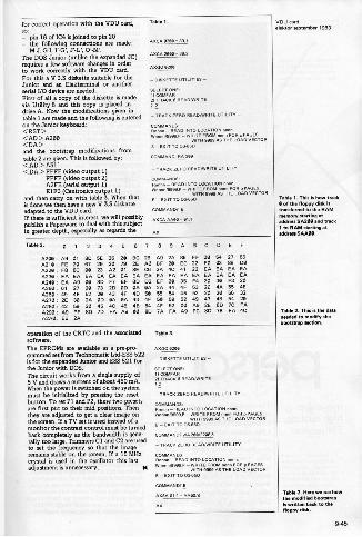
for correct operation with the VDU card,so:- pin 18 of IC4 is joined to pin 20- the following connections are made:
The DOS Junior (unlike the expanded JC)requires a few software changes in orderto work correctly with the VDU card.For this a V 3.3 diskette suitable for theJunior and an Elekterminal or anotherserial I/0 device are needed.First of all a copy of the diskette is madevia Utility 8 and this copy is placed indrive A. Now the modifications given intable 1 are made and the following is enteredon the Junior keyboard:<FtST ><AD > A200<DA>and the bootstrap modifications fromtable 2 are given. This is followed by:<AD> A311<DA> FFFF (video output 1)
FFFF (video output 2)A2FE (serial output 1)E1F3 (Centronics output 1)
and then carry on with table 3. When thatis done we then have a new V 33 disketteadapted to the VDU card.If there is sufficient interest, we will possiblypublish a Peperware to deal with this subjectin greater depth, especially ae regards the
Table 1.
SELECT ONE:COI.WAR
al TRACK 0 READAVRITE
- TRACK ZERO READPNRITE UTILITY -
O LOCATION nnnnWnnnnned99,P (WRITE FROM nrInn FOR p PAGES
WITN SEDS AS THE LOAD VEC OR3 - EXIT TO 038513
COMMANW RA 200
- TRACK EERO READ/WRITE UTILITY
COMMANDS,
Wnnn"'"'" W 7= TTR1.AVTORE - EXIT TO 03.13
COMMAND? E.
AXCA AMIE 01,1
Table 2.1 2 3 4 5 6 7 8 9 A BCDEF
A200: A8 01 80 SE 26 20 BC 26 AB ark 85 FF 20 59 27 BS
A210 FE 20 67 29 30 79 or A0 BF 20 EC 22 FO 03 88 DO
*220 FS 130 MI 23 A2 01 BE 06 2A 4C 41 22 EA EA EA EAA230: EA EA EA EA EA EA EA EA EA EA EA EA EA EA EA EAA240 EA All 00 on or EF eD 02 EF 20 35 F4 20 30 F3 20
A250: 61 27 20 73 2D OD OA OA an 44 9F 63 20 4A 55 4E
A260 49 4F 52 20 43 4F 4D 50 55 59 95 62 20 20 56 32
0270 20 30 2A OD OA OA 43 4F 50 59 52 49 47 413 54 20
02130 42 EP 20 45 40 45 an 54 4F 52 00 A9 2E BD 7C FA
A290: 09 FE 813 7D FA A9 00 813 7A FA A9 FC SD 7B FA 40A2A0: ES 2A
Operation of the CRTC and the associated Tame,.software.The &PROMs are available ae a pro-pro- AXGO
grammed set from Technomatic Ltd.ESS 522is for the expanded Junior and DES 521 for - DISKETTE UTILITIES -
the Junior with DOS.The circuit works from a single supply of TigsTai2,:r
5 V and draws a t of about 450 mitt. TRACKREADAVRITEcurren 1 aWhen the power is switched on the system -must be initialized by pressing the reset - TRACK ZERO READANRITE taw, -
button. To set PI and P2, these two presetsCOMMANDS
are first put to their mid positions. Then Rannn - REPO RiTO LOCATION men.they are adjusted to get a clear image on nnnnn/90RIP - WRITE FROM nnnn FOR p PAGES
the screen. If a TV set is used instead of a WITH MBASTMS LOAD VECTOR
monitor the contrast control must be tamedE - EXIT TO01450
back completely as the bandwidth is gene. COMMAND/ WA 200/2200,11
rally too large. Trimmers Cl and C2 am usedto set the frequency so that the image - TRACK ZERO READ/WRITE UTILITY -
remains stable on the screen. If a 15 MHz COMMANDS
crystal is used in the oscillator this last Rennn REA. INTO LOCATION ^new
adjustment is unnecessary. Mmenet., - WAITE FROM nnnn FOR p PAGES
YIT.H WWI AS THE LOAD VECTOR
COMMAND) E.
AXSA 01,1. AAOWS
AX
VDU cardalaktor somember 1883
Table T. This is how OleicII of dm flossy disk istreader. to the RAMmemory smrting ataddress SA2911 one track
to RAM starting ataddrassSAMIO.
Table 1. This is the datanomble to modify Mabooms. section.
Tahiti 3. Here we see howthe morlif. howslre0is written back to thefloppy ch..
945
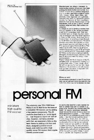
elekto s bar 1983 Manufacturers are always interested inminiaturising receiver circuits and they keeppushing the limits further and further. In anormal receiver set-up extreme integrationri to be avoided especially as regards tuningcoils, ceramic filters, band filters, andtrimmers. Coils especially are a problem.Certainly they could be replaced by gyratorcircuits, but because of their complexitythese also have certain disadvantages at highfrequencies, such as low Q factor, limiteddynamic range and fairly high current con-sumption.So Philips set out to develop a receiver thatwas less sensitive to the various problemsposed by IC technology itself. And theysucceeded with an 18 pin chip that needsonly an oscillator and a few small capacitorsto form an FM receiver. Everything else isinternal, from the aerial input right throughto the IF filters and demodulator! The breakthrough came when they decided to aban-don accepted practice and chose to ow anFLL system (a type of feedback PLL). Thissystem works with a low enough IF (inter-mediate frequency) so that the IF selectivitycan be realised with RC filters which, unlikeLC filters, can be miniaturised successfully.Moreover, the disadvantages inherent in thislow IF were suppressed by using a clevermuting system.Figure 1 shows the block diagram of the IC,complete with the components needed for abog -standard radio. A very simple affair!We will not go any further into this blockdiagram at the moment as we will concen-trate on how this circuit is expanded intosomething more interesting.
Micro or miniWe are always interested in new ICs and howthey can be used and this is the case with theTDA 7000. Now that we've decided we want
personal FMminiaturehigh qualityFM receiver
The relatively new TDA 7000 fromPhilips is an IC that forms the basis ofa complete FM receiver just by addinga few passive components. This ICcould be described as an 'aerial signalin - low frequency signal out' sort ofchip. However, not being satisfiedwith that, we expanded a little on thebasic theme by adding a bit here andthere, designed a printed circuitboard, and ended up with a highquality mono FM receiver that is quiteliterally pocket sized!
to use it as the basis fora radio receiver wehave to deride what sort of receiver it isgoing to be. Should it be a normal small FMradio? Or maybe something extremelysmall? Should the accent be not so much onsmall dimensions as quality ...? The charac-ter of the IC is an invitation to make a microradio ... but that's easier said than done!A real micro design does not seem sointeresting. There are limits to how small itcan be made if it is to be put on a printedcircuit board and we would not seriouslyconsider anything else. So what we want isa 'bigger than micro' design with somewhathigher quality and without the disadvantagesof the 'as small as possible' design. It mawhave a suitable low frequency amplifier
9-46
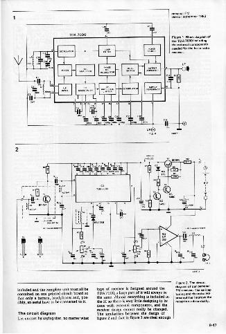
V
TDA 7000
MS El El111 El El
MI
TPA Bi{1Ck (1111,1I1.111 ofthe 7000 incluMngMeexternalneeded for the basic radioreceiver.
10.14.7111.111. 0B
2
included and the complete unit must all becontained on one printed circuit board sothat only a battery, headphones and, pos-sibly, an aerial have to be connected to it.
The circuit diagramLet us start by saying that, no matter what
type of SOMAVer iS designed around theTDA 7000, a large part of it will always bethe same. Almost everything is included inthe IC so there is very little designing to bedone with external components, and thereceiver design cannot really be changed.The similarities between the design offigure 2 and that in figure I are clear enough
Figure 2. The circuitdingrem lA nut ParaFM receiver. The redcaptuning and Me marefpreamplifier improve thereception substantially.
9-47
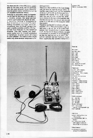
but there are also a few differences, princi.pally in the input stage and the oscillator.Also the more advanced design (figure 2)includes power supply stabilization and theLF amplifier mentioned before.Although in principle a small loudspeakercan be used for the output of the radio, itis intended, initially, that small personalcassette type headphones should be used.A secondary advantage of headphones isthat the lead can act as an aerial. To avoidmaking the receiver any bigger and morecomplicated than absolutely necessary weused a readily available amplifier IC (theLM 386 from National) for the headphoneamplifier. This chip supplies very goodsound quality and, for a small loudspeakeror headphones, its power output of 0.5 wattis quite sufficient! Furthermore the LM 386needs only three external components (R4,
C19 and C20).There are a few qualities of the basic designthat we were not entirely happy about. Inthe first case it was found that the sensitivityof about 7 µV is a bit on the low side for apersonal FM rmeiver. If you walk aroundwith that sort of radio receiver the aerialis not always in the most ideal position andthe chances are that the nation that you aretuned in to will continually disappear .derthe squelch.Therefore we decided to include a HF pre-amplifier (T1). TMs preamplifier stage isvery easy to set up, not at all critical andensures that the sensitivity 6 always .derI µV. As the circuit diagram shows, its inputis connected to one side of the headphonesso that the lead can act as . aerial. TheL4/C2I network has two functions. Apartfrom suppressing any spurious components
elektar Mr 1983
Parts firs
Resiston:RIA13.18 kR2. 1k8R3 - 292114 .07 kRS- 88 kRO,R9 .10 kflT.1001/RIO. 100P1 - 10 k ten turn potP2 - 22 k lop pot
Capacitors:CLC2 - 68 p ceramicC3 .40 ceramicCA05,020 -10 n arms.Ce 1 g/8C7,C19 .07 n prem.08- 2n2C9X12 3n3C10.013. 180p ceramicC11.Cle 330 p ceramicC14 -100nC16. 220 pC12. 150 nC18 = 220 nCal .10g/eV
C22 220g/10 VC23 . 100 0/6 V
Semiconductors:01 - BB 1050, AA 119T1 BF 490T2= !SCIPIOT3,T4 - BC 549CIC1 - TOA 7000
supplier: Tachnematic Ltd.102. LM 386
Inductees:LTL2 .0.22 pH (coil on
Toko former)L3 = 52511NA 100110
ITokolLO - inductance madewith cower OP....Me printed circuit board
Miscellaneous:
Leightesaipt iseadOomo.at least 8 R imp.ance
9-48
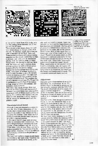
ror sep tem.. 1983 e: ::
Ill .!.... MI 111111111" 111111111 of the output signal from IC2, it also actsas a decoupling circuit between the LF out-put and the HF input.There are also a few details about the oscil-lator which should be changed. First of allthe cod. To alleviate supply difficulties weused a standard off Me -shelf Toko coil.There ere two problems with using a tuningcapacitor for this circuit: availability is oftena problem and some sort of mechanicalgearing must be used in order to maketuning easier. We decided to kill two birdswith one stone and used a varicap diode(D1) in combination with a 10 -turn poten.tiometer (PI) for the control voltage.Because the tuning voltage must remain verystable, some form of voltage stabilizationmust be used. In order to Ware the (small)battery as much as possible, the losses (vol-tage drop and current consumption) of thestabilizer should be small. This explains theuse of a discrete circuit here (T2, T3 and T4)in preference to an IC. Even if the batteryvoltage drops to 5.5 V this stabilizer stillsupplies a constant 4.5 V.And that is the whole circuit. Note thatpin 3 of the TDA 7000 is left unconnectedbecause it was considered that using squelchsuppression with artificial noise is going a bittoo far. For anybody who wants to use thisbuilt in noise generator, a 22 nF capacitorcan be connected between pin 3 and thepositive supply.
The printed circuit boardAlthough it was not intended as a micro ch.suit, the 50 x 50 mm dimensions of thedouble sided printed circuit board shown infigure 3 still make it very diminutive for acomplete FM receiver. Even when the 9 Vbattery is included the end resuk can justlybe called a personal receiver.In the case of the HF stage there are abso-lutely no problems with construction. Theworst thing is trying to remember the typenumber of the oscillator coil, L3. It is anE 526 HNA - 100114 from Toko, and that'squite a mouthful for 'the morning after thenight before'. However, L4 is not so difficultas it is already etched onto the printed cir-cuit board.The input and oscillator stages should ideallynot be able to 'sea' each other. Therefore thearea around T1 should be screened, prefer-
ably with mu -metal or copper. Space hasbeen left on the board for these screens andtheir locations are indicated. The four piecesof screen are soldered into a box and thensoldered to the upper side of the printedcircuit board. Most of this upper side (orcomponent side) of the board is an 'earthplane'. Therefore, all points which should beconnected to earth are soldered to the topof the board and the rest simply connect tothe under side. These latter (non -earth)points are of course the copper 'islands'.When construction of the printed circuitboard is completed, only the tuning andvolume potentiometers (P1 and P2 respect.ively) have to be connected, not forgettingthe battery and headphones of course. Theconnection points are clearly marked.
AdjustmentNormally quite a large section of an articledemibing the construction of an FMreceiver would be devoted to setting up, butthat is hardly necessary with the TDA 7000.The simple adjustment of L3 to ensure thecorrect receiver range (87.5 . .. 104 MHz) isall that is required. That can be done with afrequency counter of course but the simplemethod is to compare it with anotherreceiver!One final point. Even though it is extremelyhandy to use the headphone lead as anaerial, it is much better to use a 60 cm (oreven 30 cm!) aerial. And that does not applyonly for this receiver, but also for any otherpersonal radio. If an aerial is used it shouldbe connected to the junction of LI /C1(aerial input) and the headphones betweenthe LF input and ground.We have spent hours listening to our FMreceiver (mainly before the moming coffeebreak? Ed.) and it must be said that it givesa very good account of itself. The sensi-tivity is reasonable and the quality of theround is actually very good. The only 'but' isthat the TDA 7000 is only a mono receiver.But you cant have everything and whoknows, maybe it is only a matter of timebefore we get a pin compatible versionsuitable for stereo. In the meantime we havea trick up our sleeve that may be just asgood but that will have to wait until -maybe the nem issue!
Figure 3. The corn onentoverlay for the double.sided board. The le ge arseof cooper on the U ger
side actsan min pain
for the circuit.
9-49
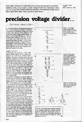
Even today, looking for simple electronic components can give you quite aheadache. Take, for example, a simple voltage divider fora voltmeter: whenyou try to buy the necessary high -stab resistors, the likelihood is that you'retold in shop after shop: 'Sorry, we don't stock those'.
ut,ision volmr
etkdiOrr sentember 1983
precision voltage divider...... for home constructionIn the construction of measuring equipment,you normally require a number of precisioncomponents. Particularly voltage and currentdividers need resistors of 1% tolerance. Thesimple four-way voltage divider shown infigure 1 has a total resistance of 1 MS2 andrequires four resistors: 900 kS2, 90 k11,9 kit and 1 lead. And that's where yourtroubles am likely to start. If you're notlucky enough to find a complete dividersomewhere, forget about buying the indivi-dual resistors. It's extremely unlikely thatyouth find the above four values in thehigh -stab range in one shop.
Parallel connectionsFortunately, it is possible to make a pre-cision voltage divider with an input im-pedance of 1 MS2 from standard valueresistors. The solution lies in connecting twohigh -stab resistors in parallel to obtain the
stocks high -stab resistors, it's pretty certainthat it has standard values oft MS2, 100 ka,and so on. And that's what the divider offigure 2 depends on! The resulting resistancesare 909.09 kit, 90.909 kit, 9.09 kit, and1.01 kn. The deviation from the ideallyrequired divide factors is smaller than0.01% so that in practice the variations areentirely dependent upon the tolerances ofthe resistors used.In parallel connections as used in figure 2,not all resistors need be 1% types. Becauseeach combination consists of two resistors ofwhich one has ten times the value of theother, the larger one has a much smallereffect on the result than the smaller one. As
consequence, the tolerance of the largerresistor is of much less importance than thatof the smaller one. Even if 5% types areused for the larger resistors in the parallelbranches, the overall stability will be suf.ficient. The same is true of R7 because thisis pretty small compared with Ro.As an example of the above: if 02 deviatesexactly 5% from its nominal value, thevariation of the resultant value of Et 1/122 isonly 0.4%. You might say that the toleranceof the larger resistor improves roughly by afactor equal to the ratio of the two resistors.Parallel connections have a fusilier advert-tage: statistically there is only a very smallprobability that two resistors in a parallel All in all, the above gives enough reasonsbranch both deviate in the same direction. to use parallel -connected resistors. Figure 3In other words: there is a good chancel that gives an alternative which uses fewer rethe network of figure 2 is more precise than sistors. However, its theoretical stability isthe one constructed from 1% resistors as rather worse than that of figure 2: 0.01%shown in figure 1. instead of 0.001%.
2
3
Figure 1. A standardvoltege divider with an
t impedance of 1 MR.unfortunately,
the re-siWors uwd are difficult toobtain.
Figure 2. This voltagedivider uses standardvalue resistors. Its inputimpedance is 5051110higher than 1 Mn, butthis will not matter in
pPliutions. TMd rWios, however,OM accurate.
Figure 3. Another possihility, but its input imp..
dance is larger still thanthat of figure 2.
9-50
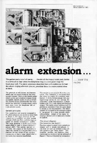
alarm extension ...The garden party is in full swing ... Amidst all the happy noises and chatterit is difficult to hear when the telephone rings or a late guest rings thefrontdoor bell. The alarm extension described here will enable you to hearthe phone ringing wherever you are, provided there is a mains socket closeat hand.
The principle is well-known: an intercomwhich uses the mains wiring asthe trans-mission channel. This is a very handy gadgetwhich can be used wherever a mains socketD available. Speech facility is not provided:the receiver merely indicates that the trans-mitter has 'detected' a certain sound, whichmay come from the telephone bell orfrom another source.
General principlesThe transmitter and receiver contained inthe alarm extension are shown in block tomein figure 1. The signal detected by thetransmitter is amplified, rectified, passedthrough a high-pass filter, and then used toswitch an astable multivibrator (AMV).This stage generates a 22 Hz square -wavesignal which is used to phase -modulate asecond AMV. This astable operates at178 kHz. The output of the modulator istaken via a limiter to a low-pass filter whichremoves the last traces of any spuriousfrequencies, ro that 'dean' signal is fed tothe maths via a suitable transformer.
The receiver is even simpler than the trans-mitter. The Delesignal' is recovered fromthe mains by means of a suitable trans-former. A diode limiter ensures that anyhigh -voltage spikes do not damage the(following) phase discriminator, a phase -locked loop (PLL) with digital and analogueoutput. The digital output lights an LED toprovide an indication when the input signalis locked to the discriminator. The demo.dulated 22 Hz signal at the analogue outputis 'recognized' by a tone decoder whichacknowledges receipt of the signal bycausing a second LED to light and a buzzerto operate.
The circuit diagramThe transmitter (see figure 2)The input signal D taken from a telephoneadapter coil or simple microphone. Acoil does not pick up ambient noise andwill therefore give better results . Theamplifier, rectifier, and high-pass filtermentioned ere shown at the top lefthand offigure 2. They are followed by comparator
... over themains
9-51
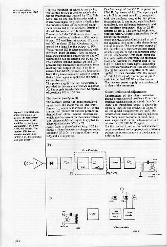
:=1:7,7:1; 98s
Figure 1. TM block di,groin contains no sur-prises: TM transmitter110 comprises bellamplifier, rectifier, acompenitor,1.m. modlator, end limiter. TMreceiver ltbl is evensimplx. cornprisimlimiter, 1.m. discrimnator,and tone decoder.
IC4, the threshold of which is set by Pl.The output of IC4 is used to switch theastable multivibrator formed by ICI. ThisAMV can be fed simultaneously with asquarawave signal to provide a facility forthe remote control of an external equip.went connected to the receiver. Details ofthis will be featured in a future issue.The second of the 555 timers is also connec.ted as an astable multivibrator. With valuesshown, IC2 oscillates at around 178 kHzand ICI at about 22 Hz. Oscillator ICI isstarted by a logic 1 at the output of IC4.The output of IC2 is phase -modulated withrelatively good hewer. Any spuriousfrequencies produced during the on and offswitching of IC1 are filtered out by 143/C9.The network around diodes D6 and D7prevents any mainshom interference fromreaching the output of IC2. The filternetwork L2/L3/C5 removes any harmonicsfrom the phase -modulated signal to ensurethat a 'clean' signal is applied to the mainsvie transformer LI.The power supply for the transmitter isprovided by the usual 5 V voltage regulatorIC. The supply trandormer must be capableof providing 9 V at 100 mA.
The receiver (see figure 3)The receiver draws the phase -modulatedsignal from the mains via Cl and trans-former LI, which is identical to 1.1 in thetransmitter. Diodes DI and D2 protect thedemodulator circuit against interferencewhich may be present on the mains voltage.The phase -modulated signal is applied tophase discriminator IC2 via C3.Apart from a phase -locked loop, IC2 in.eludes a phase detector, a voltage -controlledoscillator (V.C.0.), an output filter (withC8), and a comparator.
The frequency of the V.C.O. is preset to178 kHz by means of Pl. The input signalat pin 3 is, as usual in a PLL, comparedwith the oscillator output by the phasediscriminator. It the input signal is phase.modulated, the difference between it andthe oscillator frequency, that is 22 Hz,appears at pin 2. The internal resistance,together with C7, forms a smoothing circuitfor the output signal.When the PLL is locked to a signal at pin 3,the signals at the inputs of the phase detertor are in phase. The consequent output ofthe detector is a constant -voltage signal,which is applied to the non -inverting inputof the comparator. This stage comparesthe signal with an internally set referenlevel and switches its output (pin 8) tologic 0. LED D7 then lights, indicatingthat 1C2 has 'received' the 178 kHz carrier.The 22 Hz signal is amplified in T1 andapplied to tone decoder IC3. On receiptof this 22 Hz signal, the output at pin 8switches on the LED D8 and the buzzer.The receiver power supply unit is identicalto that of the transmitter.
Construction and adjustmentConstruction of the alarm extensionshould present no real problems if our twospecially designed minted circuit boards areused. The transmitter board is shown infigure 4, that for the receiver in figure 5.As no special components are used, theconstruction needs no further explanation.One thing must be home in mind, how.ever: capacitor Cl in both transmitter andreceiver MUST BE 600 V types!On the receiver board a thin metal screenmust be soldered to the appropriate solderingpoints: the screen is shown in the diagram asa dotted line.
la
Mem
b
9.52
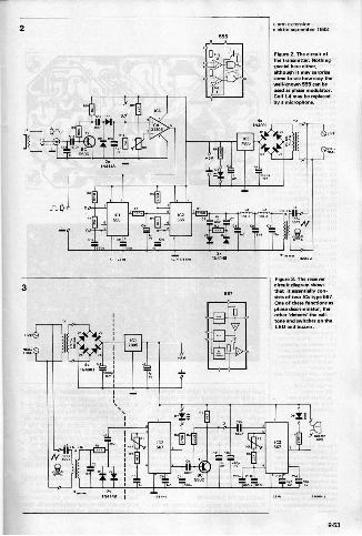
2alarm extension ...alektor september 1983
6212 ISS1P4148
WIMP011121k=
SSS
Figure 2. The circuit ofthe transmitter. NeMingspacial here either,although it may sun..some to see how easywell.known 563 [an beused as phase modulator.Coil L4 may be reiMmedby a microphone.
3567
Figure 3. Tbe receivercircuit diagram showsthat it essentially con-sists of ovo les tyPe O3E.One of these functions asphase discriminator, Meother biatects' the call.tone and switches on MeLED a. buzzer.
9.53
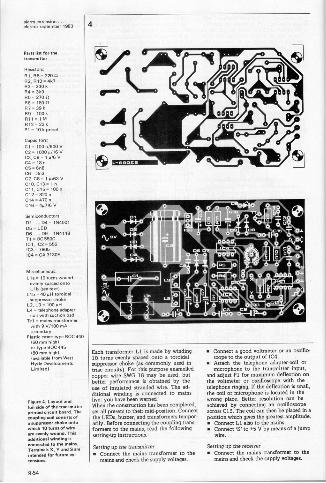
4
Parts list for thetransmitter
R I, R8 .2200R2,010. 41t7R3- 330kO 4 - eke05. 270 056 - 180 n07.39 kR9 - 100 k
F112 - 22 kPI 10 k preset
Capacitors:C1= 100 n/600 VC2-1000 pin VC3, CO. 1 a/6 VC4- 18nC5 -6n8C6. 3n3C7, C11. 1 4/63 V010, C13 - 1 nC11,C15. loonC12. 820nC14 a 470nC16 4p7/6 V
Semiconductors:D1... D4-164001D5 LED06... D9 = 164148T1 - BC 5500ICI, IC2 - 555IC3 - 7805ICA CA 3130E
Miscellaneous,
Ll a 10 turns woundevenly spaced ontoL lb (we tent)
L11). 404. tom..suppressor Moke
L2, L3 100 v.- telephone adapter
coil with suction padTrl . mains transformer
with 9 V/100 mAsecondary
Plastic case- type 900 440(50 trim high)or type BCC 445IBo mm highl(available from WestHyde DevelopmentsLimited)
Figure 4. Layout andfoil tide ot the transmitterprimed circuit board. Thecoupling coil consists ofa suppressor Make ontowhim 10 turns...irean wen!, wound. This*Intone! winding isconnected to the maims.Terminals X, V and are
intended for future ex-tensions.
Each transformer LI is made by winding10 turns evenly spaced onto a toroidalsuppressor choke (as commonly used intrim circuits). For this purpose enamelledcopper wire SWG 18 may be used, butbetter performance is obtained by theuse of insulated stranded wire. The ad-ditional winding is connected to mainslive: you have been warned!When the construction has been completed,set ad presets to their mid -position. Connectthe LEDs, bursar, and transformers tempor-arily. Before connecting the coupling trans-formers to the mains, read the followingsetting -up instructions.
Setting up the transmitter Connect the mains transformer to the
mains and check the supply voltages.
Connect a good voltmeter or an oscillo-scope to the output of IC4.
Attach the telephone adapter -coil ormicrophone to the transmitter input,
and adjust PI for mairimum deflection onthe voltmeter or omilloscope with thetelephone ringing. If the deflections small,the coil or microphone is located in thewrong place. Better resolution can beachieved by connecting an oscillomPeacross C13. The coil can then be placed in aposition which gives the greatest amplitude. Connect LI also to the mains. Connect '9' to .5 V by means of a jump
tvire.
Setting up the receiver Connect the mains transformer to the
mains and check the supply voltages.
9-54
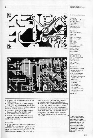
5 alarm extension ..efekror september 1963
Connect the coupling transformer LIto the mains.
Adjust PI till LED D7 lights brightly.This LED will already light, but a pos-
ition of PI should be sought where it lightstwice as brightly as normal! Adjust P2 till LED DS lights brightly.
Same remarks as for LED D7 apply. Remove the jump wire from 'T Finally, with the telephone ringing,
check the entire alarm extension forsatisfactory operation.
Final notesla If the sound of the small buzzer is too
feeble for your purpose, a relay can beconnected (via an isolating diode) in itsplace. The tone decoder can deliver up to100 mA output current. The relay can be
used to switch on a bright light, a siren,or similar optical or acoustical device. Although a Government Health Warning
is not printed on every mains socket'bear in mind that both L la windings amat mains potential. Therefore, extremecare when handling the printeduse circuitboards with the mains supply switchedon Please, gentle reader, do not becomea statistic!
Parts lim for the receiver
Resistors:R1, R2, R5 -4k7R3, R7 = 270 ftR4 - 220 kR6 22 k
P1 = 5 k presetP2=10 k preset
CepecitomC1=100n/600y02-15nC3- 2n204 = 1000 c/16 VC5, C11 = 1c/6 V
- 1 nC7 -680PC8 -1.C9,C124C15 6130 n
C10 - 470 0/13 VC126 -1120n013= 07/6 VC14- 10c/6 V
Semiconductors:01, 02 - 114414803 ... 06 if 114400107,08 -LEDT1- BC..1C1.7605IC2, IC3 c 567
Miscellaneous:L1a = 10 turns wound
evenly spaced ontoL1b (see mall
L16= 40µR toroidalsuPPressor choke
Trl = mains transformerwith 9 V/100.4secondary
Plastic case - typeBOC440150 mm high)or Woe BCC..180 mm high)(available from West
i)v.Ze DevelopmentsLimited)
Buyber,6 V
Figure 5. Layout andfoil side. the receiverprinted circuit board.The coupling coil is madeexactly as that for thetransmtte. Again, theadditional winding isconnected. the main.Terminal X is intendedfor possible future extension.
9.55
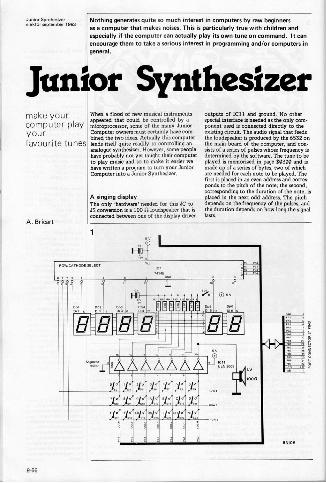
=rszt=7,- Nothing generates quite so much interest in computers by raw beginnersas a computer that makes noises. This is particularly true with children andespecially if the computer can actually play its own tune on command. It canencourage them to take a serious interest in programming and/or computers ingeneral.
Junior Synthesizermake yourcomputer playyourfavourite tunes
A. Bricart
When a flood of new musical instrumentsappeared that could be controlled by amicroprocessor, some of the many JuniorComputer ovmers must certainly have com-bined the two ideas. Actually this computerlends itself quite readily to controlling ananalogue synthesizer. However, some peoplehave probably not yet taught their computerto play music and so to make it easier wehave written a program to turn your JuniorComputer into a Junior Synthesizer.
A singing displayThe only 'hardware' needed for this JC toJO conversion is a 100 0 loudspeaker that isconnected between one of the display driver
outputs of IC11 and ground. No otherspecial interface is needed as the only com-ponent used is connected directly to theexisting circuit. The audio signal that feedsthe loudspeaker is produced by the 6532 onthe main board of the computer, and con-sists of a series of pulses whose frequency isdetermined by the software. The tune to beplayed is memorized in page $0300 and ismade up of a series of bytes, two of whichare needed for each note to be played. Thefirst is placed in an even address and cormsponds to the pitch of the note; the second,corresponding to the duration of the note, isplaced in the next odd address. The pitchdepends on the frequency of the pulses, andthe duration depends on how long the signallasts.
1
ROW/CATHODE SELECT
4 is
9-56
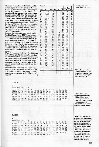
There are four values of duration possible:minim, equal to two crotchets, each equalto two quavers which in turn are each equalto two semiquavers. The durations arecalculated from the computer clock whichhas a frequency of 1 MHz. For example, thenote 'A' at 440 Hz has a pulselength of2.28 ms. With a symmetrical waveform, thespace lasts 1.19 ma There is already a timingstage mailable in the computer (DELAY).So for our 'A', this delay has to be executed81 times before inverting the logic level(81 x 14 ps at 1.14 ms). Thus the hexa.decimal value of the pitch of this note is$51 (81 in decimal).Because the program iv very simple, onlythe $0300 page (up to $03FF) can be usedto memorize a melody, so it can only have127 notes at most. The tempo is fixed bythe contents of location MOLT ($0002)which can be changed to increase or decreasethe speed of play. The rhythm is detemiinedby the magnitude of the bytes in the unevenaddresses, although, of course, the value ofthe durations also varies with the pitch ofthe naes.When the processor finds the value $00 ineven address (pitch), it is silent fora certainanlength of time which is normally determinedby the contents of the immediately follow-ing uneven address. If on the other hand,the value $00 is in an uneven address thetune is stopped and Marts again from thebeginning.In the example given here, the Junior playsthe Menuet du Bourgeois Gentilhomme byJ. B. Lolly, but with a little experimentationyou can probably make it play 'Chopsticks'as well!
Table I
Note Ha pitch code J 44-)5 1318.5D# 12..5
IBID F9
80 427C 3E
1174.5C. 1108.7
IE20
513
DE75 331
6F 321046.5988
2220
DI013
68 3483 31
A0 932.3880
26
29
BABO
5D 2F58 2C
G. 830.680
2B2E
A690
53 2A05 27
F. 7.5980
3033
9484
2546 23
5 559.2522.2
3639 F9
847C
42 213E
.7.3554.3
D41
EBDE
75BF
35 ID37 IC
523.208
DI 6963
34 IA31 19
456.1A .0 40
51BABO
5058
2F 172C 15
G. 415.3392
56
58A690
53OE
2A 1527 14
F. 370309.2
61
66848C
OA
4825 1223 11
329.8311.1
5C23
847C
0235
21 10iF 10
293.5277.2
7981
256F
3A37
ID 00IC Or
251.58 247
8991
8963
34
31
IA OD19 Oc
A* 233.1A 2206
99A2
5D58
2F2C
17 Oc18 00
G. 207.5196
AC68
53 2A27
15 0014 0A
00 50 70 38 IC
00
JUNIOR
tiCXDUMP: 200,25E
0200:0 1A9 7F
2 380 81
4 5IA A9
6 708 80
8 9ABCDEF82 IA A9 00 85 00 A9 02
0210: 85 02 A6 00 BD 01 03 85 01 FO 85 A9 40 80 80 IA0220:0230:
20 53
50 0202 A6C6 01
00 BCDO 85
00 03C6 02
FO 08DO D8
A9 BFE6 00
8D 80E6 00
IA 20A2 FF
0240:0250:
CA EAA6 00
EA EABC 00
DO FA03 A2
4C OE02 CA
02 0000 FD
00 0088 DO
DO 00F8 60
00 00
JUNIOR
HEXDUMP: 300,36B
0300.01251 58
330 EA
4 5
41 DE6 7
31 758 9ABCDEF36 84 51 58 48 63 56 9C
0310:0320.
61 4531 75
56 4E36 84
6C 8451 58
61 9448 63
79 3A51 90
51 5861 48
3D EA58 4E
41 DE6C 84
0330:0340:
61 9456 53
79 3A51 BO
61 9451 58
56 4E31 EA
51 11048 63
51 5841 68
48 6341 63
48 6351 58
0350:0360:
31 7561 4A
30 75511 45
48 636C 84
41 DE79 74
3D 7500 70
51 5800 00
48 63 58 9C
Table 1. The codes for thepiuh and duration of thenotes shown here can ma.the Junior Computer playyour favourite tune.
Table 2. This is Meprogram which uses the6532 and the displaydriver to generate an audiosignal that is heard throughthe louMpeaker. Nophysic...oration to the
Table 3. The semenu reproduced here correspondsto the notes and Bourgeois ofthe Minuet du Bourgeois
TC.en tailvhonmbmL containthe pitches end the unevenaddresses ate Me durationsof the notes. Note that insome cases the durationsare not exactly minims.The Sec et 503513 an as
repeat ban It indicatesthat the piece is to bereplayed from the sun.
9-57
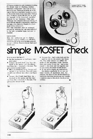
All home constructors are constantly lookingfor simple ways of checking whetherelectronic components they have in stockare fit for use. This is particularly so in thecase of the more expensive transistors, suchas the power metal -oxide field-effect transis-tors, or simply power MOSFETS, as used,for example, in the Crescendo amplifierfeatured in our December 1982 issue.Although the complete electrical testing ofsuch devices requires complicated, expensivetest gear, it is perfectly feasible to checkthem with a multimeter.The tests described refer to nthanneldevices; by reversing the test leads indicatedin the text, p -channel types can also bechecked.
Gate to source
With the multimeter set to highestresistance range (x 10M12 or x 100 MR)check that the resistance between gate andsource is infinite. Reverse the test leads andcheck again.
simple MOSFET cOrton to source Isee figure 11
Set the multimeter to the lowest resist.mice range.
Connect the (red) lead from the n ter-minal to the soume, and the (black)
lead from the - terminal to the gate. Thegate is now forward biased. Move the black lead from the gate and
connect it to the drain. The multimetershould now indicate zero ohms (see figurela) Connect the (black) lead from the -
terminal to the source and the (red)one from the terminal to the gate. Thegate is now reverse biased.
Connect the - lead to the drain and thepositive one to the source (see figure
lb). The meter should not deflect be-cause of the equivalent diode betweendrain and source. If now the lead is con.nected to the drain and the negative oneto the source, the meter should deflect. If the above checks are satisfactory,
the device is perfectly fit for use. Asmany months of experience with, forinstance, the 20K135 and 25150 MOSFETshas shown that these devices are very reliable,a negative result of the above checks is veryunlikely.
la
11\
\00)eck
8-58
Simple phase shifter for bridgecircuitThe question is often raised regarding thePwsibility of obtaining more outputpower with two identical power amplifiersin a bridge circuit.According to ...principle,. ampliliarsconnected in a bridge circuit theopetically produce four times Me outputpower of single amMifier W thinrnesupply voltage. The loudspeaker thebridge is provided wiM mine Me Sod..However, this also means that the poweramplifiers mum sup. . the outputcorr.. A normal, propedy rat
doesstage does not have Mk current reserve.
When a bridge circuit is used, therefore,the result is not necessarily .ur times thepower, but a somewhaut lower figure (de-pending on Me rnwirnm output currentof the amplifier). If the amplifier is notMM.. with a current limiting circuit,there is also a risk of overloading Meoutput tranistors.Now lex us examine the question of drive.The two amplifiers must be driven inIshars-opoositions the loudspeaker is thenconnected between the two amplifieroutputs. A suitable phase shifter consistsof e transistor stage with emitter and
collector resistors of the same value. Thesignal at the collector is then identicalwith that at the emitter, but shifted by180°. This is exactly what we ne. toMi. two amplifiers in a bridge confetti,ation. Thanks to the relatively high .1.lector current of the 00135, the outputimpedance of phase shif.r describedhere is so low .at even amplifiers with aninput impedance of only 1 k can be conetted without problems. On the otherhand, the 20 k in impedance of thephase Witter Is high enough to allow theusu.l preamplifiers to be connect..
ear PPM emplane. Mummer circuits'83 mg* 3481We regret Mat one illustration of thedouble.plated prin.-circuit board ofthis amplifier was omitted from MeSummer Circuits '83 issue. At the sametime, the foileide was omitted from thePC board pages. Both omissions are putright in the PC board pages in this issue.
morse converMr (may 1983pegs 5.521Owing to an error in our master EPROM.the hexdotop Ito ble - page 6,58) needse corremion) in address 868 the byte EB
men-nobinson comingcarry out the amendment quite siMOrs. 1- PP Ba'
should . erne.. to OB. Readers who
because the RAM of the expanded orlies m address ENC. The .1low. should *19 -Ofmbe ty0. mi
EB6CEIS. 6CEBBE BB JMP (MC
After the program has been copied to.ress 0003 and following, EA must beentered at addresses 9032... 9034.These amendments do NOT apply tpthe DOS Junior.
floppy -disk interface for the Junior(December 1982 page 12-481Our attention has been drawn to a smallomission in the Ocern.r 982 articleon the 00S Junior. In the 3.3 version ofthe DOS Junior these is an ExtendedMonitor which permits, among othwMings. BREAK pointso br Pits. in
Program Some readers who thisdiscovered it was not quite posible.ed Thisis because the BREAK vwtor is notlocated corremly. All t.t's needed to putmatters right is. after switMing on themonitor, to place Me following data intothe /dresses indicted.
SIFAJE 3268.7F ore
Thus, the BREAK vector points to theroutine which controls the BREAK poi..
elektor infocerd 70We regret that several errors and omissionscrept into infocard JO. The value ofespisciton CI ... C16 =150 pF. FF2 doesnot haw a .16: this Mould . pin 10.The dividerrs.nters are not type 4013SA...901TFinally, an RC combination and Modewere omitted: the connection beFF1 and the MK 50338 M.se be as
shown below.
elektor infected 55The formulas for Me gain of both theWien -Robinson la.geco and twin, filters
mein errors. The rrect formulas are:
soon ...Twin, filters _pt Central heating controller
J 11 -p= p 16 0. BasicodeSimple anemometer
where 0- fHm ... and many more!
9 tt9
Multi -purpose DILswitchThe Erg SO61-015 is low cost, single
e tingle throw, dual in switch. Ithas a very low profile, 5 mm high. Theswitch is fully base -sealed and besides itsobvious uses in miniature and subminia-
ture .uipment, is ideal for o -boardprogramming without the need for boardremoval from close racking systems. Theswitches can be stacked on a standard2.50 min p.c.b. pitch. Switching capabilityexteMs from 1 pA tot A up to a maxi-mum of 10 VA Inital contact reisnceis typically 20 rryl,i a. insulatisonta resistance 100 Ga.
Erg Components,Luton Road,Ormatable,Bedfordshire CUB OLLTelephone: 058062241
12646 MI
Multimeter temperaturemeasurementAnyone who has access to a digital multtmeter can now use it as a versatile vviderange temperature measuring instrumentusing standard type K thermocouples, bYadding the ovierC lut&fete unit.This new device, at considerably lowercort than a dedicated instrument, hastemperature rynge of - 50°C to .103°Cand incorporates automatic cold junction...nation. Thermocouples are at -
tad. tryough a miniature comp...socket. A basic thermocouple and mating
LED switchesAmbit has added to its range of ALPSswitch ...Es with the new SPASseries of LED illuminated witches. Theswitch is able with a choice of red,green. orange and yellow LEDs, withcorresponding diffuser caps (plus a cleardiffuffr option].
Either self locking ortomomentar ction
is
thewith 120 gm pressure..r-
ate the single pole contacts. LED illumi-nation is independent of the wvit.ingaction.The switch is carefully designed withsealed base as a result of the use of insertmolding techniques.
Ambit International,200 North Service Road,Brentwood,Essex Ch114 4SG.
12641 IN)
Ultra violet exposure unitElectronic Assistance Ltd. announce theirnew UV800 ultra -violet exposure unit.Using four 15 wart high efficiency ActinicUV lamps, it is capable of photo etchingover 800. ems of preeensitised circuitboards or labls in less than 3 minutes.Timing for the UV fluorescent tubes is
based on the ZN 1039E precision timerwhich achieves 0.116 repeatability over awide temperature range.The flame retardant foam pressure pad hasbeen design. to follow a large radius arc
Plug are suppli. as rtandard with theinstumet. The output of 1 mV per
degree centigrade is via 0.75 metre coiledlead fitted with mm plugs. Long termrtability is
Itand the low battery
drain allows it to be used for continuousmonitoring if necessary. Since the ccu-racy is not affected by the output loading,it may also be used to interface lowoutput impedance instruments such as
chart ecorders.
Graham Ball Orerurnentation,PO Sox 220,39 Corey.. Lane,Sheffield, 580TH.Telephorre 0742.082370
(2649 MIwhen being closed thus preventing relativedisplacement of artwork a. subject.
positively interlocked microswitch pre-
vents when. reaching the operator's
tryto when mapressure pad is raised.Also available is the smeller UV -300 unitwhich dispenses with thertmer but retainsthe safety features.
Electronic <resistance GM,Unit 1,Wreberth 'manure, Estate,Rhayader,Powys LP 6 SEN.Telephone: 0597.810711
12637 MI
Power booster amplifiersIn addition to their existing 15 Watt1.81 mono povver booster amplifier I LP
introdury the NEW low pric. STEREO15 V.( 111.1 per chanryl version.Both modules are esign. to increase theoutput power of existing low wattage carradio/cassette players giving the grivnnrageof being able to overcome ro. a. enginenoise without introducing annoying distootion. In addition to their being compactand roburt land in encapsulated modularform), they have many important featuressuch as easy two -hole fixing, Krew ter
mina! connection blocks for easy wiring-., automatic supply on swtcAon, selec-tble input level facility and outputprotection circuit,/LP Electronire Ltd.,Graham Bell Hausa,Roper Close,Canterbury,Kant CT2 ;EP.Telephone: 0227.54778
12653 M/
9-60
elektor sereember 1063
DILswitchDud in -em Arne SDOS-10-0.the 1 irst in a new series from Erg. Pins aresp.ed on a Ofin matrix in such a yray asto allow a saving al 30% ot px.b. arenContaining 10 onreff switches. the modulecan be edge.mounred to allow program-ming without removing a p.c.b. fromequipment. Front panel switching mnmsily and economically achieved bysimply edge -mounting the switch on the1 tont edge M the p.c.b., a. cutting esmall, maAhing, rectangle in the panel. Noa.itional mounting hardware is required.E.h switch in the module can reliablyswitch from 1 0V/14A up to 10 VA. It isPurPose designed for use on modern flowsoldedng and solvent cleaning areemblylines.
The base is totally sealed and the top isfactory sealed with a removable, trans-Porsnt tape. All SOOS switches meetBS 9565 and exceed MIL -583504. Colour.cod. a. numbered switch membersshow clearly the status of each individualswitch at a glen.. All switching cormctshave one micron minimum of cobalthardened gold over 2,5 microns nickelbarrier for long and reliable switching Irfe.T. nylon case is flame proof to BS 2071Pt2.1117. The total SDOS tangs willinclude switches from 2 to 18.way.Erg Components,Luton Road,Constable,Beds LLISTelephone: 058262241
/2730 Ml
Rugged calculatorAlready tried and tested by users Aelemn different countries, the HD 2202Sexecutive calculator and HD 9000$.ientific calculator are now available inAe UK from Lawtons Limited. Tailor -ma. to withstand the rig.rs of daily usein f.torim, off ices and on site, theLaw. HD calculators have been der-I.ed a. perfected over a period of sixyears and feature a unique robust covercase support.Protecting the mIculator like a turtle inits .ell, the hinged plastic cover is keptfirmly locked by six strong mouldedhooks, yet folds back to form a calculatorsuPPort for table or desk top use. The201 angle of the folded cover means thecalculator is easy to read and opera. evenat a distanm, thus leaving more desk spamfor working documents a. notebooks. A
special machine, built to test the strengthof the cover hinges, has opened and 410.the cover mse 2,739,416 times a. is stilltrying to break itlSp.ially construe. with a stainless steelplate reinforcing the LCD display area,both mloulators are strongly built win.battery springs ma. of hard stainlesssteel a. connections bemeen batterysprings a. circuit .ords of solderedwires.Designed for maximum simplicity in usethe executive calculator h. all the usualmathematical functions which might berequired. The automatic power shut-off8.9 minutes after the last entry ensures anoperating life of 10,000 hours . oneleakproof lithium battery.The more sophistimred scientific mIcuslator with full ttatisticol functions featurestrue algebraic operating with no less than
00,1:29 rrtrtZrA.""=137:rations and perentheSeS prevents mostcommon errors. The 11 digit internalprecision ensures accurate results under allcircumstances. One leak-proot ii.iumbattery ensures 3,000 hours of troublefree operatioo
Guarantied for 18 months the executivemlcuiator is priced at ES1.95 and thescientific calculator at 13.65 ex VATwith quantity discounts available.Leptons Limited,Station, 6 SMrelhs ChM..60 Vauxhall Road,"WIWI L69 34U,Telephone: 051-227.1212
12741 M)
New multiswitchContraves Industrial Products Limited ofRuislip, Middlesex, have introdumd a new'Z' Series to their range of Multiswachthumbwheel switches. Designed as a morecompact version of the well established'D' switch, the 'Z' Multiswitch is a stepindex, 10 position switch with BCD ordecimal output codes. Its site. 15 mm
high x 7.62 mns wide x 18 mos diametermakes it ideal for use in compact in.,mentation where space is at a premium.Basle techniCal data includes: - ratedcurrent Iresittive load) 1-100 mA; maxi-mum current carrying Cop.ity 0.6 A;Assisi.. working voltage 50 V; testvoltage 500 V; contact resiston. 100 mohms; permissible ambient temperature
Contreras Industrial Products Limited,Times House,Station Approach,
Middlesex HAP 6LH,Telephone: 08956.301g6.
/27300)
New Books
Practice Design of Digital arca.' bylan Karnpel 11.1ewnes Technical Books).This is one of the more interesting booMwhich reached us during the summerrnon.s. Names Technical Bmks hasa name for puMishirre .orevalurefor-money works and the present one is rsoexception. Practical Design of prersalCircuits' is, true A its title, eminently
Practical in its approach. To quote theautism in his foreword: 'There is no needtor the designer to know how particularICs function Arernally, for he us. them. black boxes.' The book is in ArmPorte: the first gives a clear, well thOught.Sill. introductiOn to basic logo, thesecond is concerned solely with digital.sign practice. and the third is dedim.to mttroproc.sors. A number of usefulappendims complete Me book. A Aim'for the practising a. aspiring designerof digital circuits alike.
9-61
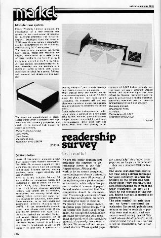
Modular case system61,n Products Limited announce the
introduction of new modular case
Netem for the construction of housingsfor electronic assemblies and instrumentdi.. .ye. Developed from the range ofDEC Cases, Me new system is designed foruM by manufacturers in the e.tronicsIndustry or by D.I.Y. anreusi.s.The new system cornpdses pre-lorrnedbody panels. lacias end moulded endcheeks. which ma. up a ene wrieWof caws, ranging in size from 2 in. by 5in. by 6 in. up to 2 in.. Sin. by 13 in.All ease semions are pre -punched for in.
Rant ..Ay and are with in a
choice of white or blwk, with naturalaluminium or Mack facia panels. Polishedteak veneered wd cheeks are also avail-
able.
The cases are manufactured in plasticwet. metal which is antistatic with highinsulation and screening properties, endcheeks are in textured high imPact resistant polystyrene.Slime Radom Limited,Lyon Wonky6pel Sweet,Sheffield S6 SNL,Telephone: 0742.339174
drawing (view... and to scale drewingeup or down as required, ere possiree.While manual entry and control are via
membra keyboard, a built in RS232Callows forne interlace with most currentomputers. An extensive sell ten wd
tlga ants. repertaire enable Me operatorquickly and easily to determine the plotterstatus.Exact registration during mono or et.,
drive system.is achieved by a new paper
drive system. Reliable, quiet and accuratestepper rnotors, contrail. by dedicatedmicroprooessors, drive both pen a.drum. With both axes plotting in in
alektor september 1983
creme. of 0006 inches, virtually ate0free traces are easily obtain.. 3.Plafrmotors a. associated logic have beenrefined by HOUS10. 1 Instruments over Owyrera to mi.. highly tunable olawation.Penertren9 repeamble plots of preciaelydefined resolution and high FICCUMCV.OPOwood Limited,30 Lancaster Fowl,St. Albans,Hanlon...ALI 4E7,Telephone: 0793.24912
12738 re)
readership12T3g M1 survey
Digital plotterHome of Instrument :mince new
" -`)"",°::1"°- °combinesTo
little
;17isO'c'ente:nef inware ZriVeZ.'70,47:0pretision. speed. rugged reliability and
ease of operation.Sizes up to and in A4 and A3are weilable on iwxcensive media. a.
V:rrlloZ, "rtg, lho7:reLre.script, Mock letters, drawings, WomMucPretarns and charts are all welleble,rrestaka-free, on ordinary bond paper,drafting vellm, acetate and mylar fromclew suppl red by your mini, micro, main-frame wmputer. or by both novice andexperienced operators. Routines withinDM/PL 111 can automatically generate
curves, arcs. ellipses arid circles of anySiZO. Elewn different lire types (solid,dotted Or dash.) we Provided Straightand Wanted Iltalic) characters can be
drawn at any of 360 possible angre. anzi255 size.. Aspect control, in Much oneaxis rney be lengthened, as .1 as thecapacity to plot only a portion of a
first results!We are still busily counting andevaluating the response to thereadership survey in our July/August edition. Although thiswork is by no means completed,some findings are already obvious. Inthe first place, some 80 per cent ofthe replies eress a genuin intrestin the resultxs,pwhile only ae fewe percent consider it 'a waste of paper'.Several readers remarked that 'thecompetition should be interested,too!' Tree enough, and most of themhave a free subscription. So here'ssomething for them to chew on.We printed the PC board layoutson special pages (mirror image, withthe reverse side blank) as an viper.iment. We thought this would makelife easier for everyone who repro-duces the boards with photosensitivematerial. Apparently, we scored ahit: over 30 per cent of our readersticked the box 'Those special pages
are a great help'! As of now, thosepages are no longer an 'experiment'- they are a standard Elektor Sea.cure!One reader even described how hehad been using a similar techniquefor years. Evidently, he erases theprinting on the reverse side withemery paper (Very carefully'), anduses sewingmacbine oil to make thepaper transparent He sent us aboard he had produced in this wayand, believe it or not, it proved to beextremely good!The other results? It's early daysyet: we haven't completed theevaluation. But we will publish themas soon as they' re available - pos-sibly even next month. Just onemore is worth noting: against 'Edi-torial introduction/opinion?', mostreaders ticked 'I'm neutral'. So, thisis not an introduction, nor is it anopinion.
982
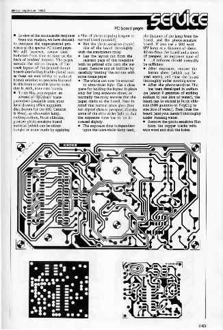
In view of the enthusiastic responsefrom our readers, we have decided
to continue the experimental pro -on of the special PC board pages.
We will, however, review theirinclusion from time to time on thebasis of readers' interest. The pagescontain the mirror images of thetrack layout of the printed circuitboards (excluding double -plated onesas these are very tricky to make athome) relating to projects featuredin this issue to enable you to make,that is, etch, your own boards. To do this, you require: an
aerosol of 830draft' trans-parentiner (available from yourlocal drawing office suppliers;distributors for the UK: Cannon& Wrist), an ultraviolet lamp,etching sodium, ferric chloride,positive photo -sensitive boardmaterial (which can be eitherbought or home made by applying
a film of photo -copying lacquer tonormal board material). Wet the photosensitive (track)
side of the board thoroughlywith the transparent spray. Lay the layout cut from the
relevant page of this magazinewith its printed side onto the wetboard. Remove any air bubbles bycarefully Ironing' the cut-out withsome tissue paper. The whole can now be exposed
to ultra -violet tight. Use a glassplate for holding the layout in placeonly for long exposure times, asnormally the spray ensures that thepaper sticks to the board. Bear inmind that normal plate glass (butnot crystal glass or perspex) absorbssome of the ultra -violet light so thatthe exposure time has to be in-creased slightly. The exposure time is dependent
upon the ultraviolet lamp used,
"41m 00
INN t .E.: - l..-
the distance of the lamp from theboard, and the photosensitiveboard. If you use a 300 wattUV lamp at a distance of about40 cm from the board and a sheetof perspex, an exposure time of4... 8 minutes should normallybe sufficient. After exposure, remove the
layout sheet (which can beused again), and rinse the boardthoroughly under running water. After the photo -sensitive film
has been developed in sodiumlye (about 9 grammes of etchingsodium to one litre of water), theboard can be etched in ferric chlo-ride (500 grammes of Fe3C12 toone litre of water). Then rinse theboard (and your hands!) thoroughlyunder running water. Remove the photo -sensitive film
from the copper tracks withwire wool and drill the holes.
963
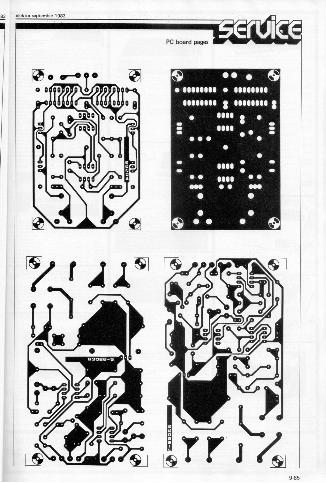
elektor uptember 198
o cr-0 (--1
PC board pages
S 99999499 44991949
90915551 = 55111111
9499
91199 11944
SOHS.
S
111.
S
1 e
trri9.65
BBC Microcomputer SystemOFFICIAL BBCCOMPUTERDEALER
100u, BBC COMPATIBLE MITSUBISHIAND TEAC SLIMLINE DISK DRIVES
* COM1r0LREariEIZOC,WOR *
PROFESSIONAL MONITORS
1_#7,....11A1 FOR RELIABILITY
SEIKOSHADOT MATRIXPRINTERS WITHHIGH-RESGRAPHICS
NEW LOW PRICES ON STAR
c?C's
POCKET COMPUTERS AND CALCULATORS
Akhter Instruments LimitedDEPT. EK, EXECUTIVE HOUSE, SOUTH MO.,
-FSIPLEFIELOS, HARLOW, ESSEX CMED 213Z. UK.TEL: HARLOW (0279)443521 OR 412639
TELEX 995001 REF -A10 OPE OuP
TE
THE AFFORDABLE DAISYWHEELPRINTER
N L Y aela6 5VATi
1.
spec...mom...mat rns lou fen 35
THE CP80 QUALITY PRINTER
NEC 8023BE-C PRINTER
elektor september 1983 advertisement
NewcastleNOW FOR THE BEST
in
IN ELECTRONIC COMPONENTSTEST EQUIPMENT
AND ACCESSORIES
MarlboroughElectronic Components
15, Waterloo Street Newcastle NEI 4DETel: 618377
Open 9arn-6pm Mon -Sat Easy Parking
STOCKISTS OFTRANSISTORS RESISTORSCAPACITORS I.C. DIODESELECTRONIC BOOKS Etc.
WESamOeuxo ROAD
,,, WATERLOO a.m.
\ REPAIRS UNDERTAKEN
1111111,,,,,-1- I
microprocessor
NgEEM[fa,z044
%S,1
Are you looking for a terminal for your micro.processor . . ? Or maybe a memory extension?Is your cassette interface too slow or just not goodenough? Computer capacity underestimated? Howdo you program your (EIPROM5? All these andmany other questions are answered in this micro-processor hardware book in clear and easy -to -under-stand language.The heart of every personal computer is the micro-processor and only a limited number of these are incommon use. This book describes a range of peri-pheral equipment which can be used with an assort-ment of personal computers using the 6502, 6809.Z80, or 8080 microprocessor. This is obviouslynot an easy matter, but the book explains all thatis necessary to enable the systems to be appliedwithnethe minimum number of circuit modifications.
Price 67.500 50p postage 8 packing.To order please use the postage paid order
card in this issue.
CIRCUIT DIAGRAM or hannfor Leak 'Point One'
"EL 10' Power Amplifier (valve(.Christopher Smith, 34 High LeysD rive, Leich LE2 52L. Tel.713942
WANTED nearly new Daisywheeltypewriter with RS232 interface.D etails to P.H. Smaliwo., Lr.TriffletOn, ieverfOrdawst.
STROBE LIGHT - £25 o.n.o.Also stereo disco miser moduleinc. controls, whistle, etc.1530. Tel. NNk on 0706 50223(evenings/.
8 MINIATURE microphones Eleach. Please include SAE. Alsosome projects a. coments.D. Martin, 29 St. JohnsClow,Leatherhead, Surrey.
RAMS, set of 8, 4116, E5,EPROM, 5 V, 2716, 2532, 2 of
AnA.rZolnEriorT.2 CPU,menu 6" scale. E20. Mr R.Minchin, 51 Thurieigh Road,London 51812 8T2.
WANTED, circuit and pinoutof SN 76489. Want to makecontact with friendly Elektorreaders for corresponding on
Vl'trsOrot ;TM l'nflTSV7i i=4th loo no. 11, Street no. 3,Nournack, Tehran 16479, Iran.
AGORNSY. 'TN fully
proportional joystick. All incustom teak cabinet, E200 o.n.o.Tel. 0264 54748 (Andover).
TELETEXT DECODER - fullspec GMT design. Cased withultrasonic remote control. E75o.n.o. plus transit charg. M.J.Hutchinson, 8 The Street,Ovinton, Norfolk. Tel. 0963883879.
ELEKTERMINAL £35. caueneinterface St. ate key keyboardE25. Ferranti vdu, faulty clock
65ikey keyboard. Offers
2137191 VITA A59 V N"ent Rix,
COMMODORE PET 8k RAM,hasic3. Lots of SAN includinginvaders, golf and database.Mole, 0934 24856.
P.S.U. Lem. 5V 3A s 12V -15V
.
OA. E25. High resolutionTV monhose, d. or picture,E05, Phone Bishop's Stanford100791504212,
WILLIAM STUART'S Big Ears
WeeM recognition system for11.01, Spr5d, Nascom, Atom.Complete with software, weer,new, £35. K.Y. Chang, JO,I -up, Ashley Street, GlasgowG3 6HW.NASOM 1 + Buffer Brd. + PSU +Transformer + Docuents, C150.Will sell separate. Mr U.K. M.46 Burnley Road East, Waterloos.Lancs. 084 9AF.WANTED: Scope Tube D07/32or D87/32. M. Rymenans, P.Coudenbehlaan21, 2520 Edegern,Belgium,
KSR TELETYPE ands[ .working order with manual. Ideal for
rolZrZIZZY4e?"'yHELM N. instructions to hulls!SOT - ENDFIELD. MNrowrifer.B. Schism, Shin-ogawa,Machi1,18, Edogewo.Apoto 56, 162Tokyo, Japan.
WANTED: 20 Spectrum circuit hag ram, advise TMS4532 -
70'L4 rAll'ff Tlia7Vibu:ehavot.liabashan, 12126 Israel.
WANTED: Circuit diagram a.workshop info. for Leak Shreo30 amplifier. Your price orborrow for copying. Philip West,2/26 Stirling Road, BirminghamB16 9BG.
STEREO DISCO MIXER., mag.netic Taus micausolade.deck switches etC. great undE50. o.n.o. Tel. nomdeiesoOMB50223
TEKTRONIX STORAGE miWilOscopes plus 0 input modules
manuals in full workingoreder. E400. complete o.n.o.St ven Bush, 37 North Pont,Woodburn Green Bucks. Tel,Bourne End 25311
SWAP. PR super speakers No.AVO (needs repair) NEAL 0
channel resolwr land Others),ef add Os1 s u.rat
Yut el,
Drunielift Rd., Thurnhy Lodge,Leicester, LE5 2LH
PROBLEMS WITH THAT PROJECT?We will - * BUILD
* TEST* REPAIR
All your Electronic Kits andprojects. Prices from only £5.00
*Call us now for a quote.*
W E B Logic Systems Ltd15 High Street, Harpenden, Herts.
05827-62119
968

- -effector september 1983 advertisement
elelatorswitchboard
rrn-zgno2n0rzvlat mag.z7v4,7gm.en°dr
kits consideredE56. Mr C. Fyson, preqmplifier unit. Will pay cost
ndnf,"= nti.t7g1I'le'wsSubZn.SO2 3SF, Shropshire 9113 7119.Tel. Shrews -
TEKTRONIX probes, two X1 TED:T
1.011, 6 ft. Lead and 8NC plug WANTE AY.36610. 7881 kitwith accessodes. E20
00.post. or ready.built. V. V.., Pile -
Tel. 108661 779855. stredet 31/320. Oslo t, Norway.SACK ISSUES P.E. 1967.1980, WANTED: CCT diagram of Soto-E.E. 1971-1978. P.W. 1956-1909, rola MPU System using 8800,
1962-1977. Offers for 6930, 6821, 6800 with Hex I/O.all or paw, say 5p a copy? S.J. Hand drawn CCT O.K. P.O.Brown, 19 Homer.. Brow, Ayworo, 28 Eboh Road OIL,Com. Down, Bath. Phone 0225 Warri-Bendel, Nigeria.832174. NASCOM 1, B.., casetl, P611,
ATONE Sates 40 channee Woes. lee., anuals, E65 o.no.4 wen FM 27MHz CB mobile Woes. ComPater + prinwr +eransceiverFull function controls, °ewe. + paper, all
ew, E30. K.V. Chang, 70, leup neWe ". nXAhley Street, Glasgow G3 ,T,ffels. 0 HIghcliffe DdYe. AII,
PET COMM 2001/16 MoMer PrXestL=VIVas°'"B.Board in order E130, add key * JUNIORmon - you have hewtof business
each,offers? Ter. Basingsto
terke 102661rt m.550 RAM chips f8Mr
G. NicMin,16 Auckland Dr.,ie RTTV for TX +
Phone 042 483587.dS. STD0
Scarab Board ZX81. Forsale - 50m RG213 brand new,
KSRTeletype for sale, E65, unused, E25 o.n.o., SOIL 1./order, used as prinwr for 30L5, vgc, E55 o.n.o. Mike Mice
computer, Phone Dave Davis c/o 6 Beaufort Avenue L I d.1urnitonl 01 399 5487. AMR awe SA3 4NU.
TE`EZUIro;`..,`,==I E85. Tel. day Gerry 629
3758, eve. 554 7267. Ilford area,collect.COMPLEX Pulse Generator, TVto 'scope +queqmeter for sale. All
convenerin same port -
Able E4). In i tes to
well, Co. Limerick, Ireland.
INFORMATION wame5 on sevl-
commended reading to circuit die -
C,;07,7"; welcomed.Menke, Redoar, Cleveland TS11)EE.
OTHER BOARD for Computer
;7= x.r1Mr G. Chester, 4 Burnett PlaceBradford. Tel. 0274735%9,ROGERS Model HGE18 Mk 11
Amp. Require circuit die-
anW.hr"LrrrnCZ:Noth E., Bulawayo,
Zimbabwe.RELUCTANT sale of radio con -
2707:"for E30. Tel. 01 504 0565.FOR38, ,S,t't 41:`,N°`4;.`7,4?E2r_e7/3. LCD + 71. etc. in E99,100.P. Tan, 2 Ridley Rod, LondonNW10. Tel. 01 961 6658.
FLUKE 82000 + 02 High speeddigital voltmeter exc forDragOn 32 or oMer homemicro.Phone Roger 01 968 6807.
HELP to suPPW or locPff °°1?Ircefor push button on IC,no. CIC910 1E. Vaill appreciateby fff Is. If ti Ahmed, P616-0,Angamura, Rawalpkharindi, Pakistan.
DISK DRIVES, Double density,Wedge sided. MPI .1352. UsewithIBM, TRS80, et, % daysfactory waranteed. Only $230.David ledid, 1162 - 52. Street,Brooklyn, NY11219,0.S.A.121214365261.
WANTED: Triac Pulse trans-formers and information on Hart-ley CT436 Scope, P. Walsh,4 Stopford Street, Edgeley,Stockeport, Cheshire. Tel, 061 429 6864evening,
HOME has new
°r2,T.',',To,. micro'
req0. .K. Jain, 17 Taylors Lan,lon.n NW10. Tc1.01 459 2563.
TURRET TAGS, tinned Mess, formourning components on PC8 ormatrix boards, small quantity,offers? Mr J.K. Potts, 42. KeswickRoad, High Lane, Stockport,C....MONO DX, isolated chassisaudio/video in/out all band tuner,825 o.n.o or swop good cassetterecorder/car player. Mr A.Bouskill, 129 Lyminster Road,Sheffield, S. Yorks. 56 1HY,el. 0]42311191 after 4.30.
EDDYSTONE 730/4 FIX, goodcondition, realigned makers las
YES). ProneWcuP13749178.
advertisingfor ourreaders!Rules:
Private advertisers only. No trade, nobusiness.Full address or private telephone number;no post office boxes.Items related to electronics only. Softwareonly when related to Elektor computer
rsterns.Maximum length: 114 characters - letter.numeral, comma. space. etc. (not
including address and/or telephone num.d.One advertisement per reader per month.To enf orce Misrule,aswitchWard voucher
v411. printed each month.Elektor cannot accept responsibility forany correspondence or transaction as a
result of a tchboard' ad, nor as a resultof any inaccuracy in the text.
Ads will . pieced in the order in whichMew are received.We reserve the right to refuse edyertisements, withour returning them.
am a priwte reader. I have read your rules a. I endow WWI switchboard voucher.Please place the following advertisement, fr., in the next available space.
BLOCK CAPITALS PLEASE -ONE CHARACTER TO EACH BOX
Nam end address:
Send taiElektor °I'IX"IIS°Ixd. All ;Wanes... must includesElektor House voucher printed here. They must10 Longport he post.rnerked within theCanterbury CT1 1PE month indicated.
Al2-MAIL
Exchange programs with friends. leave or rand messeges from the..us Billboard services. talk to computer ureaux. or placeorders and check stock levels on Maplin's Caahtel service.1000 Modem will binge a whole new workl .0. computer andwady incr... potential.Nosy you can exchange data with a, other computer using a 300baud European standard ICCITT1 rn.em a. because the M.O.,Madam use s ,s standard you could talk to any one of tens ofthousands of existing users.Some computers need an interface and we have kits for the .81.VIC20/Commodore 64, Dragon and s.tly Spectrum and AtariMfilst the BBC reeds only a o,./ program... is listed.n PreeceBook 8A, Maplin Modern will add a new dimension to your ho.
Order Alt LW99ri (Modem Kiri excluding case. Price /39.95.V1(1328 (Modern Case] Price 89.96.
Full construction deeds is Protests Book 5.
NEW MAPLIN STOREOPENS IN MANCHESTER
Our new Manchester store offer-ing the full range of Maptin'seGctrone components, compters and software wit, be OPeniny160 August, 1983. Pan of 0enew store will a wdservice
,area where you can browsearound and choose the parts youwant Counter service willavailable as well Upstairs you willfind our computer .monstratioarea with displays of hundredsand tundre. of different soh,ware packages for Atari, BBC,Commodore W. Dragon, Sot 815.Spectrum and VIMYou will find us 110 Oxford Roadopposite the BBC. between Peca.dilly and IN UnrversiN come..Were mat a few steps from
M ncnester's Oxford Road station
thea about five minutes walk from
mor centre There is excellentpaera.ng osn meters in theaboutadtecenisid a. we're fiveminutes drive raht in from10.00 10. the 186ig3 atthestanOf the M56
W and we w seen,
Great ProjectsFrom E&MM
Our new book -Bee of E&MMProjects Vol. 1- Mims together21 twinkle.° end nem, Ple-ileMe born Elk1616, first war.
Protects tnclude Harmony Gen-erator, Guitar Tuner ...run,Sy... Auto Swell. Ponying.
Booster MOS.FETand other musical hi and car
Amp
Order As 0116111. Prise L1.
CATALOGUEOver 390 pagesPacked with dataand pictures a.
all completety re-vis ed end incl.-
over 1C00 newitems On sale inall branchesof W.H. Small Price rl 25 Or
our Hero is a superbly documentedmailiorder
address weaMkit kitOrder As H820. (Robot KM Price 51,599.9s.
Maplin's Fantastic ProjectsNIK 4241£5,
Al sv1.
Full details in our projectbooks. Price 70P elWri.
In Boo. 1 (X4018) 120Wma 00566, Combo -Amplifier Universal Timer with 18 pro-gram times and 4 outputs Tempera., Gauge Six VeroProtects
ic Book 2 0.020) HorneSecurity System Train Con.troller for trains on one circus
Stopwatch with multiplemod. Miles-periGallonMeter
In Book 3 (X403131 ZX81Keyboard wt. electronics Stereo 25WMOSFET Ampli-fier Doppler Radar IntruderDetector Remote Control forTrain Controller
In Book 4 (XPOSE) Tele-hone Exchange for 16 eaten. Proects . Book 8 were in an
eons Frequency Counter advanced stele at the lime al10Hr to 600 WO Ultras.c Ming, but contents mar
coder DeIPCIOr I/0 Port for tinge pmt publi.hon Nuenal Car Burglar Alarm 13th August 19831.
Bernet. Control for 25W StereoAMP.
In Book 6 (XAO6F) Modern toEuropean standard ICON?2401/ AC Inverter SoundsGenerator for .81 CentralHeating Control!, Panto But-ton for Home Security System Model Tram Protects Timer forExternal Sounder
In Book 6 Pftb06G) SpeechSynthesiser for .81 & VIC20Module to Bridge two 0 ourMOSFET amps to make a 350WAm ZX81 Sound on your TV Scratch Filter Damp MeterFour Simple Protects
In Book 7 (X40714) ModesIRS2321 Interface for 2X81/VIC20 Digital Enlarger Time/Controller OXers Audio Pro-cessor Sweep Oscillator C11,4.11S CrystBook al
1852321 Interface for Dragon (X40811 Made
VIC Extendihoard Synchime Electrons Lock lab PowerSupply Loge Probe Door -tell for the Deaf
LEARN ROBOTICS* 1983 * - with Hero 1: tho new robotwho sees, hems. speck: enddetects movement!This remarkable micrOPmeess.ron.1. robot is the perfect roboticstraining system for inairiSt,, hiSneand schools Hero 1 .n see hearWeak delect rnowng and station.,obects and determine their distance.0, up small obtects, move in anYdaemon and can learn from your
ii
pma Liin "'''''''gL2n14:1°' '1:4Mirr,:iciv"'"""8 Oubrd Raid Manch eeeee i 081 236 0281 Opens 18M Aug 19831
ELECTRONIC SUPPLIES LSO f,1,!1=4;,4,,tpirp,==p,,,,,,..,n,h,.,,,,,,,