university of engineering & management,jaipur lecture … · types of insulator, voltage...
TRANSCRIPT

UNIVERSITY OF ENGINEERING & MANAGEMENT,JAIPURLecture-wise Plan
Subject Name: Economics for Engineers Subject Code: HU-501Year: 3RD Year Semester: Fifth
ModuleNumber
Topics Numberof Lectures
1
1. Economic Decisions Making – Overview, Problems, Role,
Decision making process.
2. Engineering Costs & Estimation– Fixed, Variable, Marginal &
Average Costs, Sunk Costs ,Opportunity Costs, Recurring And
Nonrecurring Costs, Incremental Costs, Cash Costs vs Book
Costs, Life-Cycle Costs; Types Of Estimate, Estimating Models-
Per-Unit Model, Segmenting Model, Cost Indexes, Power-Sizing
Model, Improvement & Learning Curve, Benefits.
10L
2
3. Cash Flow, Interest and Equivalence: Cash Flow–Diagrams,
Categories & Computation, Time Value of Money, Debtre
payment, Nominal& Effective Interest.
4. Cash Flow & Rate Of Return Analysis–Calculations,
Treatment of Salvage Value, Annual Cash Flow Analysis,
Analysis Periods; Internal Rate Of Return, Calculating Rate of
Return, Incremental Analysis; Best Alternative Choosing An
Analysis Method, Future Worth Analysis, Benefit-Cost Ratio
Analysis, Sensitivity And Breakeven Analysis. Economic
Analysis In The Public Sector – Quantifying And Valuing
Benefits & drawbacks.
6L

3
5. Inflation And Price Change–Definition, Effects, Causes, Price
Change with Indexes, Types of Index, Composite vs Commodity
Indexes, Use of Price Indexes In Engineering Economic
Analysis, Cash Flows that inflate at different Rates.
6. Present Worth Analysis: End-Of-Year Convention, View point
Of Economic Analysis Studies, Borrowed Money View point,
Effect Of Inflation & Deflation, Taxes, Economic Criteria,
Applying Present Worth Techniques, and Multiple Alternatives.
7. Uncertainty In Future Events-Estimates and Their Use in
Economic Analysis, Range Of Estimates, Probability, Joint
Probability Distributions, Expected Value, Economic Decision
Trees, Risk, Risk vs Return, Simulation, Real Options.
6L
4
8. Depreciation - Basic Aspects, Deterioration &Obsolescence,
Depreciation And Expenses, Types Of Property, Depreciation
Calculation Fundamentals, Depreciation And Capital Allowance
Methods, Straight-Line Depreciation Declining Balance
Depreciation, Common Elements Of Tax Regulations For
Depreciation And Capital Allowances.
9. Replacement Analysis- Replacement Analysis Decision Map,
Minimum Cost Life of a New Asset, Marginal Cost, Minimum
Cost Life Problems.
10. Accounting–Function, Balance Sheet, Income Statement,
Financial Ratios Capital Transactions, Cost Accounting, Direct
and Indirect Costs, Indirect Cost Allocation.
8L
TOTAL NO. OF HOURS= 30L

UNIVERSITY OF ENGINEERING & MANAGEMENT,JAIPURLecture-wise Plan
Subject Name: Electrical Machines-II Subject Code: EE501Year: 3rd Year Semester: FifthModule Number Topics Number of Lectures
1
Single phase induction motor 10L
1. Construction, Double revolving fieldtheory 3L
2. Starting methods 1L
3. Phasor diagram, Speed — Torquecharacteristics, Condition of maximumtorque
2L
4. Determination of equivalent circuitparameters, Applications
2L
5. Single Phase AC series motor,Compensated & uncompensated motors
2L
2
Synchronous machines 18L
1. Construction 1L
2. Armature Winding, winding factors 2L
3. Excitation systems 1L
4. Armature reaction 1L
5. Theory for salient pole machine, Tworeaction theory
2L
6. Voltage regulation (EMF,MMF,ZPF) 3L
7. Parallel operation of Alternators 3L
8. Synchronous machine connected to infinitebus, effect of change of excitation and speedof prime mover
2L
9. Construction and Starting of Synchronousmotor
2L
10. V- Curve, Damper winding. Hunting 1L
3
Special Electromechanical Devices 7L1. Principle and construction of Reluctance
motor1L
2. Permanent magnet machines, BrushlessD.C machines
1L

3. Stepper motor 2L
4. AC servo motors 1L
5. Principle, Construction and operationalcharacteristics of Induction Generators
2L
Total Number Of Hours = 35L
Faculty In-Charge HOD, CSE Dept.

UNIVERSITY OF ENGINEERING & MANAGEMENT,JAIPURLecture-wise Plan
Subject Name:-Power System-I Subject Code:-EE502Year: Third Year Semester: -FifthModule No. Topics Planned
Lectures(H)
1.
Overhead transmission line:- 8 H1. Choice of frequency and Choice of voltage 1 H
2. Type of conductors 1 H3. Inductance and capacitance of single phase. 1 H4. Three phase symmetrical configuration. 1 H5. Three phase unsymmetrical configuration. 1 H6. Bundle conductors. 1 H7. Transposition concept of GMD and GMR 1 H8. Influence of earth on conductor capacitance 1 H
2.
Overhead Line construction:- 4 H1. Line support 2 H2. Tower, poles, Sag, Tension and Clearance. 1 H3. Effect of wind and Ice on Sag, Dampers. 1 H
2.
Insulators:- 4H1. Types of Insulator, Voltage distribution across a
suspension insulator string1H
2. String efficiency, Arching shield and rings. 1H3. Methods of improving voltage distribution across
the Insulator string,1H
4. Electrical test on line Insulators. 1H
3.
Corona: 5H1. Principle of corona formation, critical disruptive
voltage.2H
2. Visual critical corona discharge potential, coronaloss.
2H
3. Advantage and disadvantages of corona, Methodsof reduction of corona.
1H
4.Cables: 3H
1. Types of cables, cable components. 1H
2. Capacitance of single core and 3 core cables. 1H3. Dielectric stress, optimum cable thickness ,
grading, dielectric loss and loss angle.1 H
5.
Performance of lines:- 5H1. Short, medium (nominal π, T) and long lines and
their representation, A,B,C,D constants,2H
2. Voltage regulation, Ferranti effect. 2H3. Power equations and line compensation, Power
circle diagrams.1 H
Generation of Electric Power:- 4H
1. General layout of a typical coal fired powerstation, hydroelectric power station, Nuclearpower station, their components and working
2 H

6.principles.
2. Comparison of different methods of powergeneration, Introduction to solar and wind energysystem.
2 H
7.Tariff and Indian Electricity Rule-1956: 1H
3. Guiding principle of tariff, different types oftariff. General Introduction
1H
TOTAL HOUR REQUIRED=34
Faculty In-Charge HOD, EE Dept.

UNIVERSITY OF ENGINEERING & MANAGEMENT,JAIPURLecture-wise Plan
Subject Name:-Control system-1 Subject Code:-EE503Year:Third Year Semester: -FifthModule No. Topics Planned
Lectures(H)
1.
INTRODUCTION TO CONTROL SYSTEM: 5 H
a) . Concept of feedback and Automatic control, Effects offeedback, Definition of linear and nonlinear systems,Elementary concepts ofsensitivity and robustness. Types ofcontrol systems
b) Objectives of control system, Servomechanisms andregulators, examples of feedback control systems
c) Transfer function concept. Pole and Zeroes of a transferfunction. Properties of Transfer function
01
02
02
2.
MATHEMATICAL MODELING OF DYNAMIC SYSTEMS: 5H
a) Translational systems, Rotational systems, Mechanicalcoupling, Liquid level systems
b) Electrical analogy of Spring–Mass-Dashpot system
c) Block diagram representation of control systems. Block diagramalgebra. Signal flow graph. Mason’s gain formula
02
01
02
3.
CONTROL SYSTEM COMPONENTS: 4H
a) Potentiometer, Synchros, Resolvers, Position encoders. DCand AC tacho-generators. Actuators. Block diagram leveldescription of feedback control systems for position control
b) speed control of DC motors, temperature control, liquid levelcontrol, voltage control of an Alternator.
02
02
4.TIME DOMAIN ANALYSIS: 6H
a) Time domain analysis of a standard second order closedloop system. Concept of undamped natural frequency
b) damping, overshoot, rise time and settling time.Dependenceof time domain performance parameters on naturalfrequency and damping ratio.
c) Step and Impulse response of first and second ordersystems. Effects of Pole and Zeros on transient response.
02
01
02

Stability by pole location.
d) Routh-Hurwitz criteria and applications
01
5.ERROR ANALYSIS: 3H
a) Steady state errors in control systems due to step, ramp andparabolic inputs.
Concepts of system types and error constants
03
6.
STABILITY ANALYSIS: 3H
a) Root locus techniques, construction of Root Loci for simplesystems. Effects of gain on the movement of Pole and Zeros
03
Module No. TOPICS Planed Lectures
7.
FREQUENCY DOMAIN ANALYSIS OF LINEAR SYSTEM: 7h
a) Bode plots
b) Polar plots, Nichols chart, Concept of resonance frequencyof peak magnification
c) Nyquist criteria, measure of relative stability, phase and gainmargin
d) Determination of margins in Bode plot. Nichols chart. M-circle and M-Contours in Nichols chart.
03
02
02
01
8.CONTROL SYSTEM PERFORMANCE MEASURE: 3H
a) Improvement of system performance through compensation. Lead,Lag and Lead- lag compensation, PI, PD and PID control
03
TOTAL HOUR REQUIRED=36 h
ASSIGNMENTS:
MODULE1:
1. What is the effect of adding feedback to a control system?2. Explain sensitivity and robustness.3. What are the differences between open and closed loop control system?4. What is stochastic and adaptive control system?

UNIVERSITY OF ENGINEERING & MANAGEMENT,JAIPURLecture-wise Plan
Subject Name:-Control system-1 Subject Code:-EE503Year:Third Year Semester: -FifthMODULE2 & 3:
1. What is an electrical analogous of spring, mass and damper system? Explain.2. What are the prime differences between block diagram reduction and signal flow
graph?3. Write a short note on potentiometer.4. Write a short note on resolver.5. Write a short note on synchro.6. What are the major methods for the speed control of DC motor? Explain the methods.
MODULE 4:
1. What is natural frequency of oscillation?2. Explain damping ratio.3. Deduce the expression for step response in a second order system.4. Deduce the expression for peak time, peak overshoot and rise time.5. Analyse the system from stability point of view with the help of Routh – Hurwitz
criteria:S6+2s5+5s4+3s3+s2+s+4 = 0
MODULE 5:
1. Explain the terms: Position error constant, velocity error constant, acceleration errorconstant.
2. What is the significance of steady state error?3. What is the effect on adding a pole or a zero in a transfer function?
MODULE 6:
1. What is root locus?2. What is break away and break in point?3. How the gain of the system varies with the variation of pole and zero?4. What is an asymptote? Explain the significance.
MODULE 7:
1. What is gain and phase margin? How they effect stability?2. What is the significance of gain crossover frequency and phase crossover frequency?3. What is resonant frequency and bandwidth?4. Explain Nyquist’s criterion.5. Compare relative stability with absolute stability.

MODULE 8:
1. Write short notes on lead and lag compensator.2. Explain the significance of P, PI and PID controllers.
Faculty In-Charge HOD, EE Dept.

UNIVERSITY OF ENGINEERING & MANAGEMENT,JAIPURLecture-wise Plan
Subject Name: Advanced OOPs using C++ Subject Code-EE504AYear:3RD Year Semester: FifthModule Number Topics Number of Lectures
1
Introduction 5L1. Basics of OOP, Features; Structure of
C++ program; Class and object;Concept of Constructor& destructor;Abstraction
2. Encapsulation; Inheritance;3. Static and dynamic
binding;Polymorphism.
2L
1L2L
2
Exception Handling 5L1. Exception handling mechanism;
throwing, catching, rethrowingmechanism;
2. Multiple catch statement; Nested try-catch block;
3. Exception in constructor & destructor;exceptions in operator overloadedfunctions.
2L
2L
1L
3
Template 6L1. Class template; Member function
inclusion; Class template with differentparameter;
2. Function template; Function templatewith multiple parameters;
3. Overloading of template function;member function template.
3L
2L
1L
4
Console I/O operations 6L1. C++ streams; C++ stream classes;2. Unformatted I/O operations;3. Formatted I/O operations;4. Managing output with Manipulators.
1L2L2L1L
5
Working with Files 10L1. Data File Handling: Need for a data file,
Types of data files – Text file andBinary file;
2. Text File: Basic file operations on textfile: Creating/Writing text into file,reading and manipulation of text froman already existing text File (accessingsequentially).
3. Binary File: Creation of file, Writingdata into file, Searching for requireddata from file, Appending data to a file,Insertion of data in sorted file, Deletionof data from file, Modification of data ina file; opening and closing files; classes
2L
4L
4L
for file stream operations; Errorhandling during file operations;command line arguments.
6
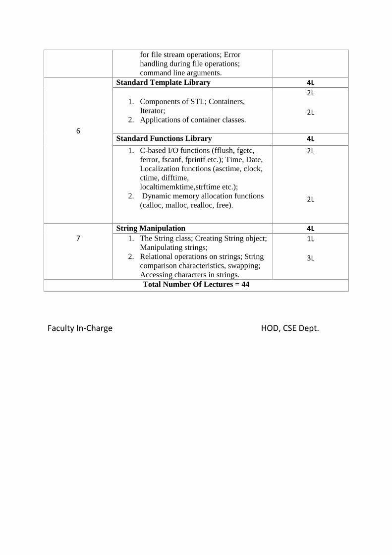
Standard Template Library 4L
1. Components of STL; Containers,Iterator;
2. Applications of container classes.
2L
2L
Standard Functions Library 4L1. C-based I/O functions (fflush, fgetc,
ferror, fscanf, fprintf etc.); Time, Date,Localization functions (asctime, clock,ctime, difftime,localtimemktime,strftime etc.);
2. Dynamic memory allocation functions(calloc, malloc, realloc, free).
2L
2L
7String Manipulation 4L
1. The String class; Creating String object;Manipulating strings;
2. Relational operations on strings; Stringcomparison characteristics, swapping;Accessing characters in strings.
1L
3L
Total Number Of Lectures = 44
Faculty In-Charge HOD, CSE Dept.

UNIVERSITY OF ENGINEERING & MANAGEMENT,JAIPURLecture-wise Plan
Subject Name: Advanced OOPs using C++ Subject Code-EE504AYear:3RD Year Semester: FifthAssignment:
Module-1: Introduction1. Write a program in which a class has three data members: name, roll no, marks of 5
subjects and a member function Assign() to assign the streams on the basis of table givenbelow:
Avg. Marks Stream90% or more Computers80% - 89% Electronics75% - 79% Mechanical70% - 74% Electrical
2. What is virtual base class? Write a small code to explain it.Why pure virtual functions areneeded?Define a function area() to compute the area of objects of different classes –triangle, rectangle, square. Invoke these in the main program. Comment on the binding(static or dynamic) that takes place in your program.
Module-2: Exception Handling1. Explain exceptions with different types. How exception is handled in C++?Write down the
steps by which we can handle the exceptions with a proper example.2. How we can restrict a function to throw only certain specified exception in C++. Explain with
proper example.When we use catch(…) handler? Explain with a proper example.Writeprograms that demonstrate how certain exception types are not allowed to be thrown.
Module-3: Template1. What do you mean by generic programming?Explain class template and function template
with proper example.A template can be considered as a kind of macro. Then what is thedifference between them?
2. What is the difference between class template and template class?Write a function template toperform linear search/ binary search/ bubble sort/ merge sort/ selection sort in an array.Writea C++ program where template function is overloaded.Explain inline function template.
Module-4: Console I/O operations1. Differentiate get(), getline() and write() function with proper example.What do you mean by
stream? Write down its different types of stream with proper example.What is streambuf?Explain stream.Why it is necessary to include the file iostream in all C++ program?
2. A. What the following statement do?i. cout.write(s1,m).write(s2,n)ii. cout.write(line, size)iii. cout.precision(a)
B. How do the following two statements differ in operation?a. Cin>>a;b. Cin.get(a);
Module-5: Working with Files1. Write a C++ program to write number 1 to 100 in a data file NOTES.TXT.Explain how
while(f1) statement detects the end of file that is connected to f1 stream.2. Explain the difference between normal text file and binary file. What are the advantages of
saving data in binary form?How many file objects are required to do the following operation?iv. To process four files sequentially.v. To merge two files into third file.

Module-6: STL1. What are the different types of algorithm in STL? Explain.What are the applications of
container class?How list works in STL? Explain with proper example.What do you mean byfunction objects? How you use function objects in algorithm?
2. A table gives a list of car models and the number of units sold in each type in a specifiedperiod. Write a program to store this table in a suitable container, and to display interactivelythe total value of a particular model sold, given the unit-cost of that model.
Module-7: String Manipulation1. What is the importance of using string class? What do you mean by C-Style string?Write a
C++ program to create string objects in C++.2. Write a program that reads the name “RAMAN KUMAR BANERJEE” from keyboard into
three separate string objects and then concatenates them into a new string object usingi. + operatorii. append() function

UNIVERSITY OF ENGINEERING & MANAGEMENT,JAIPURLecture-wise Plan
Subject Name: Computer Organization Subject Code: EE504BYear: 3RD Year Semester: FifthModule Number Topics Number of Lectures
1
Introduction to digital computer organization 7L
1. Concept of basic components of a digitalcomputer, High level view of computer.
2. Commonly used number systems3. Fixed and floating point representation of a
number4. Booth’s Algorithm – restoring and non
restoring.
6L
5. What are the H/W resources that we willneed in computer
6. Conversion of high level code to m/c levellanguage.
1L
2
CPU design 3L
1. Basic organization of the stored programcomputer and operation sequence forexecution of a program.
2. Description of ALU, Design of circuit of asmall scale CPU
2L
3. Fetch, decode and execute cycle, Concept ofoperator, operand, registers and storage,Instruction format. Instruction sets andaddressing modes.
1L
3
CPU design - Timing and control 2L
1. Timing diagram and control design 2L
4
Micro programmed control 5L1. Concepts of Micro operations2. Horizontal and vertical micro-program3. Optimization of hardware resources for
designing of micro-programmed controlunit
5L
5
Pipeline concept 3L1. Instruction and Arithmetic Pipelining,2. Synchronous and Asynchronous
pipeline3. Solving problems on pipeline speed-up,
efficiency, throughput
2L
6
Memory Organization 5L1. Static and dynamic memory, Memory
hierarchy, Associative memory, Baremachine
3L
2. Memory unit design with special emphasison implementation of CPU-memoryinterfacing.
2L

UNIVERSITY OF ENGINEERING AND MANAGEMENT, JAIPURLecture-wise Plan
Subject Name: Computer Organization Subject Code: CS304Year: 2nd Year Semester: Third
7
Cache memory Architecture 4L1. Cache memory organizations, Set
associative cache1L
2. Techniques for reducing cache misses 1L
3. Discussion on Buffer cache 2L
8RAM architecture 2L
1. Basic concepts of architecture of RAM2L
9
Discussion on DRAM & SRAM 3L1. Architecture of Static Ram and
Dynamic Ram 2L
2. Difference between SRAM and DRAM 1L
10
I-O subsystem organization 3L1. Concept of handshaking, Polled I/O 1L
2. Interrupt and DMA 2L
Total Number Of Hours = 37L
Faculty In-Charge HOD, CSE Dept.

UNIVERSITY OF ENGINEERING & MANAGEMENT,JAIPURLecture-wise Plan
Subject Name: Computer Organization Subject Code: EE504BYear: 3RD Year Semester: Fifth
Assignments:-
Unit 1:-
1. What is the role of operating system?2. Discuss the basic organization of digital computer.3. Convert (1B3F)16 (?)84. Why do we need 2’s compliment method?5. Briefly explain IEEE 754 standard format for floating point representation in single precision.6. Using Booth’s algorithm multiply ( – 12 ) and ( + 6 ).7. Explain various assembler directives used in assembly language program.8. Write +710 in IEEE 754 floating point representation in double precision.
Unit 2 + Unit 3 + Unit 4:-
1. What are the advantages of micro programming control over hardwired control?2. Write down the control sequence for Move (R1), R2.3. Define hardwired control.4. Discuss the principle of operation of a micro programmed control.5. Write the control sequence for execution of the instruction Add(R3), R1.6. Give the organization of typical hardwired control unit and explain the functions performed
by the various blocks.7. Explain the multiple bus organization in detail.8. What is microprogrammed sequencer?9. Design a basic ALU which can perform 8 different arithmetic and logical operations.10. Design the basic block diagram of Intel microprocessor 8085 and discuss the working
principle of the different parts of it.
Unit 5 :-
1. What is pipelining?2. What are the major characteristics of a pipeline?3. What is a pipeline hazard?4. What is the use of pipelining?5. What are the remedies commonly adopted to overcome/minimize these hazards.6. What is the ideal speedup expected in a pipelined architecture with n stages. Justify your
answer.7. Draw the structure of two stage instruction pipeline.
Unit 6 + Unit 7 + Unit 8 + Unit 9 :-
1. Define Memory Access time for a computer system with two levels of caches.2. How to construct an 8M * 32 memory using 512 K * 8 memory chips.3. Write two advantages of MOS device.
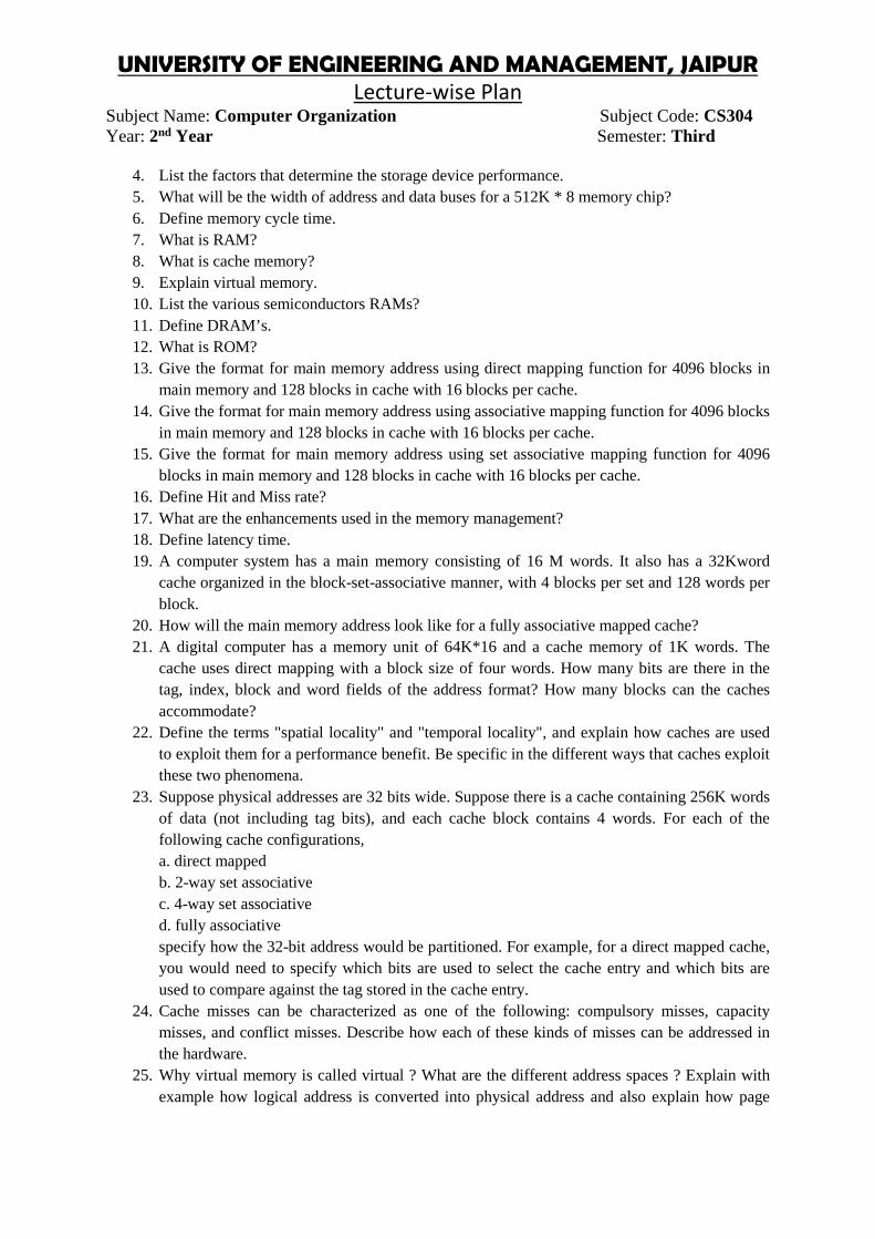
UNIVERSITY OF ENGINEERING AND MANAGEMENT, JAIPURLecture-wise Plan
Subject Name: Computer Organization Subject Code: CS304Year: 2nd Year Semester: Third
4. List the factors that determine the storage device performance.5. What will be the width of address and data buses for a 512K * 8 memory chip?6. Define memory cycle time.7. What is RAM?8. What is cache memory?9. Explain virtual memory.10. List the various semiconductors RAMs?11. Define DRAM’s.12. What is ROM?13. Give the format for main memory address using direct mapping function for 4096 blocks in
main memory and 128 blocks in cache with 16 blocks per cache.14. Give the format for main memory address using associative mapping function for 4096 blocks
in main memory and 128 blocks in cache with 16 blocks per cache.15. Give the format for main memory address using set associative mapping function for 4096
blocks in main memory and 128 blocks in cache with 16 blocks per cache.16. Define Hit and Miss rate?17. What are the enhancements used in the memory management?18. Define latency time.19. A computer system has a main memory consisting of 16 M words. It also has a 32Kword
cache organized in the block-set-associative manner, with 4 blocks per set and 128 words perblock.
20. How will the main memory address look like for a fully associative mapped cache?21. A digital computer has a memory unit of 64K*16 and a cache memory of 1K words. The
cache uses direct mapping with a block size of four words. How many bits are there in thetag, index, block and word fields of the address format? How many blocks can the cachesaccommodate?
22. Define the terms "spatial locality" and "temporal locality", and explain how caches are usedto exploit them for a performance benefit. Be specific in the different ways that caches exploitthese two phenomena.
23. Suppose physical addresses are 32 bits wide. Suppose there is a cache containing 256K wordsof data (not including tag bits), and each cache block contains 4 words. For each of thefollowing cache configurations,a. direct mappedb. 2-way set associativec. 4-way set associatived. fully associativespecify how the 32-bit address would be partitioned. For example, for a direct mapped cache,you would need to specify which bits are used to select the cache entry and which bits areused to compare against the tag stored in the cache entry.
24. Cache misses can be characterized as one of the following: compulsory misses, capacitymisses, and conflict misses. Describe how each of these kinds of misses can be addressed inthe hardware.
25. Why virtual memory is called virtual ? What are the different address spaces ? Explain withexample how logical address is converted into physical address and also explain how page
UNIVERSITY OF ENGINEERING & MANAGEMENT,JAIPURLecture-wise Plan
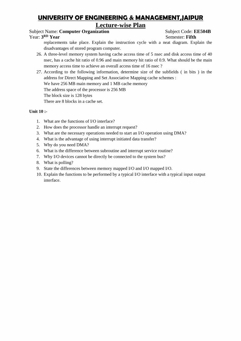
Subject Name: Computer Organization Subject Code: EE504BYear: 3RD Year Semester: Fifth
replacements take place. Explain the instruction cycle with a neat diagram. Explain thedisadvantages of stored program computer.
26. A three-level memory system having cache access time of 5 nsec and disk access time of 40nsec, has a cache hit ratio of 0.96 and main memory hit ratio of 0.9. What should be the mainmemory access time to achieve an overall access time of 16 nsec ?
27. According to the following information, determine size of the subfields ( in bits ) in theaddress for Direct Mapping and Set Associative Mapping cache schemes :We have 256 MB main memory and 1 MB cache memoryThe address space of the processor is 256 MBThe block size is 128 bytesThere are 8 blocks in a cache set.
Unit 10 :-
1. What are the functions of I/O interface?2. How does the processor handle an interrupt request?3. What are the necessary operations needed to start an I/O operation using DMA?4. What is the advantage of using interrupt initiated data transfer?5. Why do you need DMA?6. What is the difference between subroutine and interrupt service routine?7. Why I/O devices cannot be directly be connected to the system bus?8. What is polling?9. State the differences between memory mapped I/O and I/O mapped I/O.10. Explain the functions to be performed by a typical I/O interface with a typical input output
interface.
UNIVERSITY OF ENGINEERING & MANAGEMENT,JAIPURLecture-wise Plan
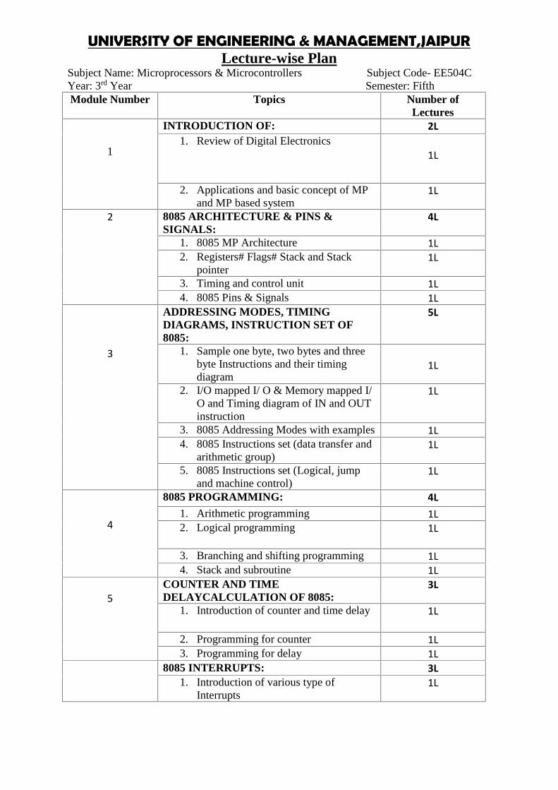
Subject Name: Microprocessors & Microcontrollers Subject Code- EE504CYear: 3rd Year Semester: FifthModule Number Topics Number of
Lectures
1
INTRODUCTION OF: 2L1. Review of Digital Electronics
1L
2. Applications and basic concept of MPand MP based system
1L
2 8085 ARCHITECTURE & PINS &SIGNALS:
4L
1. 8085 MP Architecture 1L2. Registers# Flags# Stack and Stack
pointer1L
3. Timing and control unit 1L4. 8085 Pins & Signals 1L
3
ADDRESSING MODES, TIMINGDIAGRAMS, INSTRUCTION SET OF8085:
5L
1. Sample one byte, two bytes and threebyte Instructions and their timingdiagram
1L
2. I/O mapped I/ O & Memory mapped I/O and Timing diagram of IN and OUTinstruction
1L
3. 8085 Addressing Modes with examples 1L4. 8085 Instructions set (data transfer and
arithmetic group)1L
5. 8085 Instructions set (Logical, jumpand machine control)
1L
4
8085 PROGRAMMING: 4L1. Arithmetic programming 1L2. Logical programming 1L
3. Branching and shifting programming 1L4. Stack and subroutine 1L
5COUNTER AND TIMEDELAYCALCULATION OF 8085:
3L
1. Introduction of counter and time delay 1L
2. Programming for counter 1L3. Programming for delay 1L
8085 INTERRUPTS: 3L1. Introduction of various type of
Interrupts1L

62. Concept of EI, DI, SIM, RIM
instructions and examples1L
3. Hardware Interrupts including INTR(Handshake Interrupt) and INA
1L
7
MEMORY INTERFACING: 2L1. Memory Chips (27 series and RAM
chips) 1L
2. Memory interfacing 3L
8INTERFACING CHIPS: 3L
1. Programmable peripheral Interface8255
1L
2. Programmable peripheral Interface8259
1L
3. Programmable peripheral Interface8237
1L
9
16-bit PROCESSOR 8086: 5L1. Architecture of 8086
1L2. Pinout diagram of 8086 1L3. Addressing mode with examples 1L4. Instruction sets with examples 1L5. Interrupts of 8086 1L
108051 FAMILY OFMICROCONTROLLER:
6L
1. Introduction and Overview of 8051family 1L
2. Architecture, Register Banks & SFRs 1L3. Pins & signals of 8051 1L4. Memory organization & External
memory access1L
5. Overview of 8051 instructions &sample programs
1L
6. Timers and counters 1LFaculty In-Charge HOD, ECE Dept.
Assignment:
Module-1:1. What is a difference between microprocessor and microcontroller?2. What is a difference between latch and flipflop?3. Discuss the evolution tree of general purpose processor.4. What is a tri state buffer? Explain briefly.5. Why microprocessor is called a “Micro” processor?6. Discuss the operation of RAM and ROM with proper diagram.

UNIVERSITY OF ENGINEERING & MANAGEMENT,JAIPURLecture-wise Plan
Subject Name: Microprocessors & Microcontrollers Subject Code- EE504CYear: 3rd Year Semester: Fifth
7. Describe the general architecture of microprocessor.
Module-2:
1. Discuss about the Flag register of 8085 microprocessors.2. Describe each function of every general-purpose register.3. Draw the architectureof 8085 microprocessors and explain?4. Using 74LS138 draw and explain the interfacing of memory and I/O device.5. What are the function of ALE, HOLD, READY, s0, s1 and Interruptpin?
Module-3:
1. Draw the timing diagram of IN and OUT instruction and explain.2. What is a difference between memory mapped I/O and peripheral mapped I/O?3. What is a difference between absolute and partial decoding?4. Describe the addressing mode of 8085 microprocessors.5. How to optimize the instruction format of 8085?
Module-4:
1. Write an assembly language program to add two 8-bit numbers.2. Write an assembly language program to add two 8-bit BCD number.3. Write an assembly language program to add two 8-bit BCD Number without using
DAA instruction.4. Write an assembly language program to subtraction two 8-bit number without using
SUB instruction.5. Write an assembly language program to add two 16 bit numbers.6. Write an ALP of 8085 to arrange the six 8 bits random numbers in ascending order by
using subroutine.
Module-5:
1. Write an ALP to generate 1 sec delay.2. Write an ALP to generate a 20 khz square wave.3. Write an ALP to generate a 20 khz triangular wave.4. The following sequences of instructions are executed by 8085 microprocessor:
C000 LXI SP, D050HC003 POP HC004 XRA AC005 MOV A, HC006 ADD LC007 MOV H, AC008 PUSH HC009 PUSH PSWC00A HLT

D050 05D051 40D052 52D053 03D054 XX
What are the contents of Stack Pointer, Program Counter, Accumulator and HL pair?
5. The following sequence of instructions are executed by an 8085 microprocessor:C000 LXI SP, D7FFHC003 CALL C008HC006 POP DC008 POP H
What are the contents of the SP and HL register pair after execution the aboveprogram?
Module-6:
1. What is interrupt? Why interrupt is very important in 8085 microprocessors?2. What is a different between maskable and non maskable interrupt?3. Draw the timing diagram of RESTART instruction.4. Explain the operation of RIM and SIM instruction.5. What is the vector and non-vector interrupt?6. Describe the interrupt process of 8085 up.
Module-8:
1. What do you mean by Mode 0, Mode 1 and Mode 2 operation of 8255 PPI?2. Discuss the control word format in the BSR Mode of 8255 PPI.3. In Mode 1 operation of 8255 PPI, what are the control signals when port A and B acts
as output ports? Discuss the control signals.4. Discuss about the DMA data transfer scheme of 8085.5. What is pulling device? Why it is very important?6. Explain the function of 8259 programable interrupt controller.
Module-9:
1. What are the main functions of BIU and EU of 8086? How does the separation inunits speed up the processing?
2. Discuss the addressing mode of 8086 microprocessors.3. Draw the architecture of 8086 and explain the function of it’s all registers.4. How does 8086 follow the pipeline architecture?5. How does 8086 generate physical address?

UNIVERSITY OF ENGINEERING & MANAGEMENT,JAIPURLecture-wise Plan
Subject Name: Microprocessors & Microcontrollers Subject Code- EE504CYear: 3rd Year Semester: Fifth
Module-10:
1. Draw the architecture of 8051microcontroller and explain it.2. Discuss the addressing mode of 8051.3. Explain the Flag register of 8051 microcontroller with example.4. What is difference between shot jump and long jump of 8051?5. What is difference between ACALL and SCALL instruction?6. Write an assembly language program to add two 8-bit numbers.7. Write an assembly language program to subtraction two 8-bit numbers.

UNIVERSITY OF ENGINEERING & MANAGEMENT, JAIPURLab Manual
Title of Course: Electric Machine-II LabCourse Code: EE591L-T-P scheme: 0-0-3 Course Credit: 2
Objectives:1. To introduce the student fundamentals of Electromechanical energy conversion2. Providing an in-depth understanding of Electrical Machine.3. To learn the role of Electrical Machines in real life applications.
Learning Outcomes: The students will have a detailed knowledge of the concepts ElectricalMachines and their operating principles. Upon the completion of Operating Systems practicalcourse, the student will be able to:
Understand constructional details, principle of operation, Performance of Induction Motors. Understand general features of alternators. Learn the concepts of voltage regulation. Learn the Concepts of Synchronous motor operation
Course Contents:Exercises that must be done in this course are listed below:Exercise No.1:Study the star delta starter of three phase induction motorExercise No. 2: Study the characteristics of three phase alternator by OCC & SCC testExercise No. 3: Perform slip test and determine Xd&Xqof an alternator.
Exercise No. 4: Perform no load and block rotor test of single phase induction motor.Exercise No. 5: Study V curve of Synchronous Motor.
Text Book:Ashfaq Husain, Electric Machines, DhanpatRai& Co.
Recommended Systems/Apparatus Requirements:Laboratory Kits, Multimeters, Connecting wires, Watt Meters.

Experiment No: 1Study the star delta starter of three phase induction motor
Aim:
To study the star delta starter of three phase induction motor
Theory:
At the standstill the motor behaves as the short circuit secondary transformer and it draws heavycurrent from mains, which can cause the damages at the starting. It can cause the heavy drops inpower line. So direct online starting of motor is not desirable. The motor has to be started atreduced voltage. For heavy duty motors some starting methods are used or resistance has to beincluded in the circuit at starting
Procedure:
1. All the six terminals of stator winding are brought out and are connected as shown in Fig.2. In the starting the stator winding is connected in start and full voltage is applied across these
terminals.3. The voltage of each phase is 1/3 of normal value. As the motor picks up the speed, the
change over switch disconnects the winding of motor.4. Now it connects the winding in delta across supply terminals.5. This method reduces the current taken by the motor to one third the current it would have
drawn if it was directly connected in delta
Observation Table:Compare the starting current and running current .
Conclusion:

UNIVERSITY OF ENGINEERING & MANAGEMENT, JAIPURLab Manual
Experiment No: 2Study the characteristics of three phase alternator by OCC & SCC test
Aim:To study the characteristics of three phase alternator by OCC & SCC test
Theory:Open Circuit Test Drive the synchronous machine at the synchronous speed using a primemover when the stator windings are open circuited. Vary the rotor winding current, and measurestator winding terminal voltage. The relationship between the stator winding terminal voltageand the rotor field current obtained by the open circuit test is known as the open circuitcharacteristic of the synchronous machine.
Short Circuit Test Reduce the field current to a minimum, using the field rheostat, and thenopen the field supply circuit breaker. Short the stator terminals of the machine together throughthree ammeters; Close the field circuit breaker; and raise the field current to the value noted inthe open circuit test at which the open circuit terminal voltage equals the rated voltage, whilemaintain the synchronous speed. Record the three stator currents. (This test should be carriedout quickly since the stator currents may be greater than the rated value).
Procedure:
1. For open circuit test the machine is driven at its rated speed without load2. Readings of line-to-line voltage are taken for various values of field current.3. The OCC is plotted with these reading4. For short circuit test The three terminals of the armature are short-circuited each
through a current measuring circuit5. The machine is driven at approximately synchronous (rated) speed and measurements
of armature short-circuit current are made for various values of field current.6. The SCC is plotted with the readings

Observation Table:
Conclusion:
Experiment No: 3Perform slip test and determine Xd&Xqof an alternator
Aim:To perform slip test and determine Xd&Xqof an alternator
Theory:In a salient pole alternator, the reactance of magnetic circuit along is along its quad stator axis. Thealternator is driven by auxiliary prime mover at a speed slightly less than the synchronous speedunder these conditions. The armature current is when the armature current mmf is in line with thefield poles. The reactance by the magnetic field current is minimum. The ratio of maximum voltageto minimum current gives the direct axis impedance and the ratio of minimum voltage to maximumcurrent gives the armature axis impedance.The values of Xd&Xq are determined by conducting theslip-test. The syn. machine is
driven by a separate prime mover at a speed slightly different from synchronous speed. The fieldwinding is left open and positive sequence balanced voltages of reduced magnitude(around 25%ofthe rated value)and of rated frequency and impressed across the armature terminals. Here, therelative velocity b/w the field poles and the rotating armature mmf wave is equal to the differenceb/w syn. speed and the rotor speed i.e, the slip speed. When the rotor is along the d-axis, then it has aposition of min reluctance, min flux linkage and max flux produced links with the winding. ThenXd=(max. armature terminal voltage/ph) /(min. armature current/ph)As the current is small then Vtwill be high as drop will be small. When the rotor is alongq-axis, then it is max, then the flux linkagewould be max. Then The min flux produced links with winding. So max emf. Xq=(min. armatureterminal voltage/ph) /(max. armature current/ph)

UNIVERSITY OF ENGINEERING & MANAGEMENT, JAIPURLab Manual
Procedure:1. Note down the name plate details of motor and alternator.2. Connections are made as per the circuit diagram.3. Give the supply by closing the DPST switch.4. Using the three point starter, start the motor to run at the synchronous speed by varying the
motor field rheostat at the same time check whether the alternator field has been opened ornot.
5. Apply20%to 30% of the rated voltage to the armature of the alternator by adjusting theautotransformer.
6. To obtain the slip and the maximum oscillation of pointers the speed is reduced slightlylesser than the synchronous speed.
7. Maximum current, minimum current, maximum voltage and minimum voltage are noted.8. Find out the direct and quadrature axis impedances
Observation Table:
Conclusion:
Experiment No: 4Perform no load and block rotor test of single phase induction motor.
Aim:To perform no load and block rotor test of single phase induction motor
Theory:No load test:

The test is conducted by rotating the motor without load. The input current, voltage and power aremeasured by connecting the ammeter, voltmeter and wattmeter in the circuit. These readings aredenoted as Vo , Io and Wo .Now
Wo = Vo Io cosΦ
The motor speed on no load is almost equal to its synchronous speed hence for practicalpurposes, the slip can be assumed zero. Hence r2/s becomes ∞ and acts as open circuit in theequivalent circuit. Hence for forward rotor circuit, the branch r2/s + j x2 gets eliminated.
While for a backward rotor circuit, the term r2/(2 - s) tends to r2/2. Thus xo is much higher thenthe impedance r2/2 + j x2. Hence it can be assumed that no current can flow through and that branchcan be eliminated.
So circuit reduces to as shown in the Fig.1.
Now the voltage across xo is VAB
But VAB = Io xo
... xo = VAB /Io
But xo = Xo /2
Thus magnetising reactance Xo can be determined.The no load power Wo is nothing but the rotational losses.
Block Rotor Test:In balanced rotor test, the rotor is held fixed so that it will not rotate. A reduced voltage is applied
to limit the short circuit current. This voltage is adjusted with the help of autotransformer so that therated current flows through main winding. The input voltage, current and power are measured byconnecting voltmeter, ammeter and wattmeter respectively. These readings are denoted as Vsc ,Isc andWsc.
Now as rotor is blocked, the slip s = 1 hence the magnetising reactance xo is much higher thanthe rotor impedance and hence it can be neglected as connected in parallel with the rotor. Thus theequivalent circuit for blocked rotor test is as shown in the Fig.2.

UNIVERSITY OF ENGINEERING & MANAGEMENT, JAIPURLab Manual
Wsc = Vsc Isc cosΦsccosΦsc =Wsc /Vsc Isc
= blocked rotor power factorNow Zeq = Vsc/ Isc
Req = Wsc /(Isc)2
But Req = R1 + R2
... R2 = Req - R1
= rotor resistance referred to statorXeq =√(Zeq
2 - Req2)
X1 = X2 we get,
The stator resistance is measured by voltmeter-ammeter method, by disconnecting the auxiliarywinding and capacitors present if any. Due to skin effect, the a.c. resistance is 1.2 to 1.5 times morethan the d.c. resistance.
Key point : Thus with two tests, all the parameters of single phase induction motor can beobtained.
Procedure:1. Note down the name plate details of the motor2. Connections are made as per the circuit diagram3. Note down the readings of Vo , Ioand Wowhile performing no load test4. Note down the readings of Vsc ,Iscand Wscwhile performing blocked rotor test5. Do necessary calculations to find out the parameters of equivalent circuit of single phase
induction motorObservation Table:
Vo Io Wo Vsc Isc Wsc
Conclusion:
Experiment No: 5Study V curve of Synchronous Motor.
Aim:To Study V curve of Synchronous Motor
Theory:
The variation of field current affects the power factor at which the synchronous motor operates. Fora synchronous motor the magnitude and phase angle of phasorIa depends upon the value of DC

excitation. When the syn. Motor is operated at constant load with variable field excitation, it isobserved that:a) When the excitation is low, the armature current is lag in nature &the magnitude is comparativelyhigh.b) If the excitation is gradually increased, the magnitude of Ia is gradually decreasing and the angleof lag is gradually reduced.c) At one particular excitation, the magnitude of Ia corresponding to that load in minimum andvector will be in phase with V vector.d) If the excitation is further increased, the magnitude of Ia again gradually increased and Ia, vectorgoes to leading state and the angle of load is also gradually increased
The plot of v curve :
Procedure:6. Note down the name plate details of the motor7. Connections are made as per the circuit diagram.8. The motor starts as an induction motor.9. Give the excitation to the field for making it to run as the synchronous motor10. By varying the field rheostat note down the excitation current, armature current and the
power factor for various values of excitation.11. The same process has to be repeated for loaded condition.12. Later the motor is switched off and the graph is drawn

UNIVERSITY OF ENGINEERING & MANAGEMENT, JAIPURLab Manual
Observation Table:
Conclusion:

UNIVERSITY OF ENGINEERING & MANAGEMENT, JAIPURLab Manual
Title of Course: Power System-I LabCourse Code: EE592L-T-P scheme: 0-0-3 Course Credit: 2
Objectives:1. To learn how to handle various electrical equipment to perform experiments of electrical
background.2. To provide an understanding of safety measures necessary to take while nurture electrical
equipment of different voltage and current level.3. To provide a window to investigate and verify various laws, theories, and concepts regarding
power system analysis.
Learning Outcomes: The students will have a detailed knowledge of electrical equipment handlingand will get to be comfortable with various safety measures and caution which is of outmostimportance to be taken while implementing electrical equipments of different voltage and currentlevel practically. The students will also get the opportunity & better understanding of variousconcepts, laws, & theories applicable regarding power system by investigating and verifying thempractically. Upon the completion of Operating Systems practical course, the student will be able to:
Understand and will be able to handle various electrical equipment to perform experiments,and as well as to design practically if required.
Use of different safety precautions for experiment or practical purposes. Analyze designed circuit to see weather various laws, theories, and concepts regarding
power system holds or not.
Course Contents:Exercises that must be done in this course are listed below:Exercise No.1: Study of Ferranti Effect experimentally.Exercise No. 2: Evaluation of ABCD parameters by Short and open circuit test of long transmissionline experimentally.Exercise No. 3: Evaluation of ABCD parameters by Short and open circuit test of mediumtransmission line experimentally.Exercise No. 4: Evaluation of ABCD parameters by Short and open circuit test of short transmissionline experimentally.Exercise No. 5: Transformer Oil Testing
Text Book:1. Electrical Power System, Subir Roy, Prentice Hall
Experiment No: 1. Study of Ferranti Effect experimentally.

UNIVERSITY OF ENGINEERING & MANAGEMENT, JAIPURLab Manual
Aim: Study and verification of Ferranti Effect on a practical circuit.
Description:
Theory
A long transmission line has a large capacitance. If such a line is open circuited or very lightlyloaded at the receiving end, the magnitude of the voltage at the receiving end becomes higher thanthe voltage at the sending end. This phenomenon is called Ferranti effect. Ferranti effect is due tocharging current of the line.The voltage magnification in a long transmission line considering the a nominal π-model due toFerranti effect can be expressed as:− = − 418 ×10Here, Vs = sending end voltage
Vr = receiving end voltagef = frequency of the lineS = electrical length of the line
In this equation we can see that (Vs-Vr) is negative. That is Vr>Vs and Ferranti effect depends onfrequency and the electrical length of the line.
CIRCUIT DIAGRAM:
Draw the circuit diagram of long transmission line considering it as a nominal π-model as
instructed in the lab.
CALCULATIONS:
Calculate the theoretical data’s got from experiment of the given circuit.
OBSERVATION TABLE:
SL. No. Variation of either S or f (Vs – Vr)
1.
2.
3.
4.
Percentage Error= [(Observed-Calculated)/Calculated]*100
RESULT:
The percentage error is found to be__%.
DISCUSSION:
Experiment No: 2. Evaluation of ABCD parameters by Short and open circuit test of longtransmission line experimentally.

UNIVERSITY OF ENGINEERING & MANAGEMENT, JAIPURLab Manual
Aim: Evaluation of ABCD parameters by Short and open circuit test of long transmission line.
Description:
Theory
The predominance of one or more of the parameters of a line is governed by its length and conductorconfiguration. The term long line refers to a line having its length more than 240km. The lineparameters like resistance (R), inductance (L), Capacitance (C) and leakage conductance (G) aredistributed uniformly along the whole length of the line. It may be assumed that a line consists of alarge number of short sections connected together.The steady state values of voltage and current at any intermitted point distance s from the receivingend for long transmission line can be written as:= 12 ( + ) + 12 ( − )= 12 + + 12 ( − )Here, Vs = sending end voltage
Vr = receiving end voltageIs = sending end currentIr = receiving end currentf = frequency of the lineS = electrical length of the line
Z0 =
Using complex exponential or power series and with the basic knowledge of ABCD parameters wecan find the ABCD parameters of long transmission line. Which looks like:A = D = cosh γs = 1+ ZY/2B = Z0 sinh γs = Z(1+ ZY/6)C = sinh γs = Y(1 + ZY/6)CIRCUIT DIAGRAM:
Draw the circuit diagram of long transmission line as instructed in the lab.
CALCULATIONS:
Calculate the theoretical data’s got from experiment of the given circuit and find out values
of parameters ABCD.
OBSERVATION TABLE:
Sl. No. When Output is open circuited (i.e. Ir =0) When Output is short circuited (i.e. Vr =0)Vs Is Vr Vs Is Ir
1.2.3.4.

UNIVERSITY OF ENGINEERING & MANAGEMENT, JAIPURLab Manual
5.
Percentage Error= [(Observed-Calculated)/Calculated]*100
RESULT:
The percentage error is found to be__%.
DISCUSSION:

UNIVERSITY OF ENGINEERING & MANAGEMENT, JAIPURLab Manual
Experiment No: 3. Evaluation of ABCD parameters by Short and open circuit test of mediumtransmission line experimentally.Aim: Evaluation of ABCD parameters by Short and open circuit test of medium transmissionline.
Description:
Theory
The predominance of one or more of the parameters of a line is governed by its length and conductorconfiguration. The term medium line refers to a line having its length in the range of 80-240km.Forsuch lines the capacitance (C) of the line cannot be neglected and t is considered to be lumped at oneor more points of the line. The effect of capacitance is more at higher frequency. The leakageconductance (G) is neglected.A number of localized capacitance models have been used to make approximate line performancecalculations. There are two common models:Nominal T modelThe steady state values of sending end voltage and current can be written as:= 1 + 2 + (1 + 4 )= + 1 + 2Here, Vs = sending end voltage
Vr = receiving end voltageIs = sending end currentIr = receiving end currentZ = series impedance of the lineY = series admittance of the line
With the basic knowledge of ABCD parameters we can write the ABCD parameters of this model ofmedium transmission line as following.
A = D = 1 +B = (1 + )C = YNominal π modelThe steady state values of sending end voltage and current can be written as:= 1 + 2 += (1 + 4 ) + 1 + 2With the basic knowledge of ABCD parameters we can write the ABCD parameters of this model ofmedium transmission line as following.
A = D = 1 +B = Z
C = Y (1 + )CIRCUIT DIAGRAM:
Draw the circuit diagram of medium transmission line as instructed in the lab.
CALCULATIONS:

UNIVERSITY OF ENGINEERING & MANAGEMENT, JAIPURLab Manual
Calculate the theoretical data’s got from experiment of the given circuit and find out values
of parameters ABCD.
OBSERVATION TABLE:
Sl. No. When Output is open circuited (i.e. Ir =0) When Output is short circuited (i.e. Vr =0)Vs Is Vr Vs Is Ir
1.2.3.4.5.
Percentage Error= [(Observed-Calculated)/Calculated]*100
RESULT:
The percentage error is found to be__%.
DISCUSSION:
Experiment No: 4. Evaluation of ABCD parameters by Short and open circuit test of shorttransmission line experimentally.Aim: Evaluation of ABCD parameters by Short and open circuit test of short transmissionline.

UNIVERSITY OF ENGINEERING & MANAGEMENT, JAIPURLab Manual
Description:
Theory
The predominance of one or more of the parameters of a line is governed by its length and conductorconfiguration. The term short line refers to a line having its length up to 80km. For such lines thecapacitance (C) is negligibly small but for cable line where the distance between the conductors issmall, the effect of capacitance cannot be ignored. In a short line the shunt capacitance C and shuntconductance G are neglected. The series resistance R and series inductance L for the total length ofthe time is considered.
The steady state values of sending end voltage and current can be written as:Vs = Vr + Z Ir
Is = Ir
Here, Vs = sending end voltageVr = receiving end voltageIs = sending end currentIr = receiving end currentZ = series impedance of the line
With the basic knowledge of ABCD parameters we can write the ABCD parameters of this model ofmedium transmission line as following.A = 1B =C = 0D = 1
CIRCUIT DIAGRAM:
Draw the circuit diagram of short transmission line as instructed in the lab.
CALCULATIONS:
Calculate the theoretical data’s got from experiment of the given circuit and find out values
of parameters ABCD.
OBSERVATION TABLE:
Sl. No. When Output is open circuited (i.e. Ir =0) When Output is short circuited (i.e. Vr =0)Vs Is Vr Vs Is Ir
1.2.3.4.5.
Percentage Error= [(Observed-Calculated)/Calculated]*100
RESULT:

UNIVERSITY OF ENGINEERING & MANAGEMENT, JAIPURLab Manual
The percentage error is found to be__%.
DISCUSSION:
Experiment No: 5. Transformer Oil TestingAim: Study Transformer Oil Testing
Description:
Theory

UNIVERSITY OF ENGINEERING & MANAGEMENT, JAIPURLab Manual
Oil, a type of insulating and cooling oil used in transformers and other electrical equipment, needs tobe tested periodically to ensure that it is still fit for purpose. This is because it tends to deteriorateover time. Testing sequences and procedures are defined by various international standards, many ofthem set by ASTM. Testing consists of measuring breakdown voltage and other physical andchemical properties of samples of the oil, either in a laboratory or using portable test equipment onsite.The transformer oil (insulation oil) of voltage- and current-transformers fulfills the purpose ofinsulating as well as cooling. Thus, the dielectric quality of transformer oil is essential to secureoperation of a transformer.As transformer oil deteriorates through aging and moisture ingress, transformer oil should,depending on economics, transformer duty and other factors, be tested periodically. Power utilitycompanies have a vested interest in periodic oil testing since transformers represent a largeproportion of their total assets. Through such testing, transformers' life can be substantiallyincreased, thus delaying new investment of replacement transformer assets.Recently time-consuming testing procedures in test labs have been replaced by on-site oil testingprocedures. There are various manufacturers of portable oil testers. With low weight devices in therange of 20 to 40 kg, tests up to 100 kV rms can be performed and reported on-site automatically.Some of them are even battery-powered and come with accessories.To assess the insulating property of dielectric transformer oil, a sample of the transformer oil istaken and its breakdown voltage is measured. The lower the resulting breakdown voltage, the poorerthe quality of the transformer oil.
CIRCUIT DIAGRAM:
Draw the equivalent line as instructed in the lab.
PROCEDURE
OBSERVATIONS:
Two standard-compliant test electrodes with a typical clearance of 2.5 mm are surrounded
by the dielectric oil. A test voltage is applied to the electrodes and is continuously increased
up to the breakdown voltage with a constant, standard-compliant slew rate of e.g. 2 kV/s.
Hence the breakdown voltage of the oil as measured is ________KV
DISCUSSION:

UNIVERSITY OF ENGINEERING & MANAGEMENT, JAIPURLab Manual
Title of Course: Control System-I LabCourse Code: EE593L-T-P scheme: 0-0-3 Course Credit: 2
Objectives:1. To provide the students with a hands-on experience on the theoreticalconcepts through simple
experiments.2. To develop the ability to designand validate their knowledge through open ended experiments.
Learning Outcomes:On successful completion of this lab course, the students would beable to1. Demonstrate and analyze the response of Transfer function for various input.2. Analyze the response of various signal like Impulse Ramp etc.3. Carry out the root locus of given signal.4. Analyse different plot and state model.5. Conduct an open ended experiment in a group of2 to 3.
Course Contents:List of Experiments:
1. To obtain a transfer function from given poles and zeroes using MATLAB2. To obtain zeros and poles from a given transfer function using MATLAB3. To obtain the step response of a transfer function of the given system using MATLAB4. To obtain the impulse response of a transfer function of the given system using MATLAB5. To obtain the ramp response of a transfer function of the given system using MATLAB.6. To plot the root locus for a given transfer function of the system using MATLAB.7. To obtain bode plot for a given transfer function of the system using MATLAB.8. To obtain the transfer function from the state model.9. To obtain the state model from the given transfer function.10. To design a lag compensator for a closed loop system.
Text Book:
1) Katsuhiko Ogata, (2002), Modern Control Engineering, Prentice Hall of India Private Ltd.,New Delhi.2) Nagrath I.J. and Gopal M., (2006), Control Systems Engineering, New Age InternationalPublisher, New Delhi.
Recommended Systems/Software Requirements:SCILAB, MATLAB

UNIVERSITY OF ENGINEERING & MANAGEMENT, JAIPURLab Manual
1 .TRANSFER FUNCTION FROM ZEROS AND POLES
AIM: To obtain a transfer function from given poles and zeroes using MATLAB
APPARATUS:Software: MATLAB
THEORY: A transfer function is also known as the network function is a mathematicalrepresentation, in terms of spatial or temporal frequency, of the relation between the inputand output of a (linear time invariant) system. The transfer function is the ratio of theoutput Laplace Transform to the input Laplace Transform assuming zero initial conditions.Many important characteristics of dynamic or control systems can be determined from thetransfer function. The transfer function is commonly used in the analysis of single-inputsingle-output electronic system, for instance. It is mainly used in signal processing,communication theory, and control theory. The term is often used exclusively to refer tolinear time-invariant systems (LTI). In its simplest form for continuous time input signalx(t) and output y(t), the transfer function is the linear mapping of the Laplace transform ofthe input, X(s), to the output Y(s). Zeros are the value(s) for z where the numerator of thetransfer function equals zero. The complex frequencies that make the overall gain of thefilter transfer function zero. Poles are the value(s) for z where the denominator of thetransfer function equals zero. The complex frequencies that make the overall gain of thefilter transfer function infinite. The general procedure to find the transfer function of alinear differential equation from input to output is to take the Laplace Transforms of bothsides assuming zero conditions, and to solve for the ratio of the output Laplace over theinput Laplace.
MATLAB PROGRAM:z=input(‘enter zeroes’)p=input(‘enter poles’)k=input(‘enter gain’)[num,den]=zp2tf(z,p,k)tf(num,den)
PROCEDURE:
1. Write MATLAB program in the MATLAB editor document.2. Then save and run the program3. Give the required input.4. The syntax “zp2tf(z,p,k)” and “tf(num,den)” solves the given input poles and zeros and
gives the transfer function.5. zp2tf forms transfer function polynomials from the zeros, poles, and gains of a system
in factored form
EXAMPLE:
Given poles are -3.2+j7.8,-3.2-j7.8,-4.1+j5.9,-4.1-j5.9,-8 and the zeroes are -0.8+j0.43,-0.8- j0.43,-0.6 with a gain of 0.5

UNIVERSITY OF ENGINEERING & MANAGEMENT, JAIPURLab Manual
THEORITICAL CALCULATIONS:
Enter zerosZ=
Enter polesP =
Enter gainK=
num =
den =
Transfer function=
RESULT:
2. ZEROS AND POLES FROM TRANSFER FUNCTION
AIM:To obtain zeros and poles from a given transfer function using MATLAB.
APPARATUS:Software: MATLAB
THEORY:The transfer function provides a basis for determining important system responsecharacteristics without solving the complete differential equation. As defined, the transferfunction is a rational function in the complex variable that is It is often convenient tofactor the polynomials in the numerator and the denominator, and to write the transferfunction in terms of those factors: where, the numerator and denominator polynomials,N(s) and D(s), have real coefficients defined by the system’s differential equation.
MATLAB PROGRAM:num = input(‘enter the numerator of the transfer function’)den = input(‘enter the denominator of the transfer function’)[z,p,k] = tf2zp(num,den)
PROCEDURE:1.Type the program in the MATLAB editor that is in M-file.2.Save and run the program.3.Give the required inputs in the command window of MATLAB in matrix format.3.tf2zp converts the transfer function filter parameters to pole-zero-gain form.

UNIVERSITY OF ENGINEERING & MANAGEMENT, JAIPURLab Manual
4.[z,p,k] = tf2zp(b,a) finds the matrix of zeros z, the vector of poles p, and the associatedvector of gains k from the transfer function parameters b and a:5. The numerator polynomials are represented as columns of the matrix b.6.The denominator polynomial is represented in the vector a.7.Note down the output of the program that is zeros, poles and gain obtained inMATLAB.8.The zeros, poles and gain are also obtained theoretically.
THEORITICAL CALCULATIONS:Enter the numerator of the transfer functionnum =Enter the denominator of the transfer functionden =
z =p =
RESULT:
3. STEP RESPONSE OF A TRANSFER FUNCTION
AIM: To obtain the step response of a transfer function of the given system usingMATLAB
APPARATUS: Software: MATLAB
THEORY: A step signal is a signal whose value changes from one level to another levelin zero time.
MATLAB PROGRAM:num = input(‘enter the numerator of the transfer function’)den = input(‘enter the denominator of the transfer function’)step (num,den)
PROCEDURE:Type the program in MATLAB editor that is in M-file.Save and run the program.Give the required inputs in the command window of MATLAB in matrix format.‘step’ function calculates the unit step response of a linear system.Zero initial state is assumed in state-space case.When invoked with no output arguments, this function plots the step response on the
screen.step (sys) plots the response of an arbitrary LTI system.This model can be continuous or discrete, and SISO or MIMO.The step response of multi-input systems is the collection of step responses for each

UNIVERSITY OF ENGINEERING & MANAGEMENT, JAIPURLab Manual
input channel.The duration of simulation is determined automatically based on the system poles
and zeroes.Note down the response of the transfer function obtained in MATLAB.The response of the transfer function is also obtained theoretically.Both the responses are compared.
THEORETICAL CALCULATIONS: Calculation will be in the form of graph.
RESULT:
4. IMPULSE RESPONSE OF A TRANSFER FUNCTION
AIM:To obtain the impulse response of a transfer function of the given system usingMATLAB.
APPARATUS:Software: MATLAB
THEORY:An impulse signal is a signal whose value changes from zero to infinity in zero time.
MATLAB PROGRAM:num = input(‘enter the numerator of the transfer function’)
den = input(‘enter the denominator of the transfer function’)impulse(num,den)
PROCEDURE:Type the program in the MATLAB editor that is in M-file.Save and run the program.Give the required inputs in the command window of MATLAB in matrix format.‘impulse’ calculates the impulse response of a linear system.The impulse response is the response to the Dirac input, δ (t) for continuous time systems
and to a unit pulse at for discrete time systems.Zero initial state is assumed in the state space case.When invoked without left hand arguments, this function plots the impulse response on
the screen.‘impulse(sys)’ plots the impulse response of an arbitrary LTI model sys.This model can be continuous or discrete, SISO or MIMO.The impulse response of multi-input systems is the collection of impulse responses for
each input channel.The duration of simulation is determined automatically to display the transient behavior
of the response.Note down the response of the given transfer function obtained in MATLAB.The response of the transfer function is also obtained theoretically.Both the responses are compared.
UNIVERSITY OF ENGINEERING & MANAGEMENT, JAIPURLab Manual
GRAPH-
RESULT:
5. RAMP RESPONSE OF A TRANSFER FUNCTION
AIM:To obtain the ramp response of a transfer function of the given system using MATLAB.
APPARATUS:Software: MATLAB
THEORY:A ramp signal is a signal which changes with time gradually in a linear fashion
MATLAB PROGRAM:num = input(‘enter the numerator of the transfer function’)den = input(‘enter the denominator of the transfer function’)lsim(num,den,u,t)
PROCEDURE:Type the program in the MATLAB editor that is in M-file.Save and run the program.Give the required inputs in the command window of MATLAB in matrix format.lsim simulates the (time) response of continuous or discrete linear systems to arbitrary
inputs.When invoked without left-hand arguments, lsim plots the response on the screen.lsim(sys,u,t) produces a plot of the time response of the LTI model sys to the input time
historyt,u.The vector t specifies the time samples for the simulation and consists of regularly spaced
time samples.t = 0:dt:TfinalThe matrix u must have as many rows as time samples (length(t)) and as many columns
as system inputs.Each row u(i,:) specifies the input value(s) at the time sample t(i).Note down the response of the transfer function obtained in MATLAB.The response of the transfer function is also obtained theoretically.Both the responses are compared.
GRAPH:
RESULT:
6.ROOT LOCUS FROM A TRANSFER FUNCTION

UNIVERSITY OF ENGINEERING & MANAGEMENT, JAIPURLab Manual
AIM:To plot the root locus for a given transfer function of the system using MATLAB.APPARATUS:
Software: MATLAB
THEORY:rlocus computes the Evans root locus of a SISO open-loop model. The root locus gives theclosed-loop pole trajectories as a function of the feedback gain k (assuming negativefeedback).Root loci are used to study the effects of varying feedback gains on closed-loop polelocations.In turn, these locations provide indirect information on the time and frequency responses.rlocus(sys) calculates and plots the rootlocus of the open-loop SISO model sys. This functioncan be applied to any of the following feedback loops by setting sys appropriately.
MATLAB PROGRAM:num=input(‘enter the numerator of the transfer function’)den=input(‘enter the denominator of the transfer function’)h=tf(num,den)rlocus(h)
PROCEDURE:Write MATLAB program in the MATLAB specified documents.Then save the program to run it.
27The input is to be mentioned.The syntax “h=tf(num,den)” gives the transfer function and is represented as h.The syntax “rlocus(h)” plots the rootlocus of the transfer function h.Generally the syntax is of the form
rlocus(sys)rlocus(sys,k)rlocus(sys1, sys2, ….)[r,k] = rlocus(sys)r = rlocus(sys,k)
rlocus(sys) calculates and plots the root locus of the open loop SISO model sys.Now we have to solve it theoretically.Now we have to compare the practical and theoretical ouputs to verify each other
correctly.
THEORETICAL CALCULATIONS:enter the numerator of the transfer functionnum=enter the denominator of the transfer functionden=
UNIVERSITY OF ENGINEERING & MANAGEMENT, JAIPURLab Manual
Transfer function :
RESULT:
7.BODE PLOT FROM A TRANSFER FUNCTION
AIM: To obtain bode plot for a givan transfer function of the system using MATLAB.
APPARATUS:Software: MATLAB
THEORY:Bode computes the magnitude and phase of the frequency response of LTI models. Wheninvoked without left-side arguments, bode produces a Bode plot on the screen. Themagnitude is plotted in decibels (dB), and the phase in degrees. The decibel calculation formag is computed as 20log10(|H(jw)|), where H(jw) is the system's frequency response. Bodeplots are used to analyze system properties such as the gain margin, phase margin, DC gain,bandwidth, disturbance rejection, and stability
bode(sys) plots the Bode response of an arbitrary LTI model sys. This model can becontinuous or discrete, and SISO or MIMO. In the MIMO case, bode produces an array ofBode plots, each plot showing the Bode response of one particular I/O channel. Thefrequency range is determined automatically based on the system poles and zeros.bode(sys,w) explicitly specifies the frequency range or frequency points to be used for theplot.To focus on a particular frequency interval [wmin,wmax], set w = {wmin,wmax}. To useparticular frequency points, set w to the vector of desired frequencies. Use logspace togeneratelogarithmically spaced frequency vectors. All frequencies should be specified inradians/sec.bode(sys1,sys2,...,sysN) or bode(sys1,sys2,...,sysN,w) plots the Bode responses of severalLTI models on a single figure. All systems must have the same number of inputs and outputs,but may otherwise be a mix of continuous and discrete systems. This syntax is useful tocompare the Bode responses of multiple systems.bode(sys1,'PlotStyle1',...,sysN,'PlotStyleN') specifies which color, linestyle, and/or markershould be used to plot each system. For example,bode(sys1,'r--',sys2,'gx') uses red dashed lines for the first system sys1 and green 'x' markersfor the second system sys2.When invoked with left-side arguments[mag,phase,w] = bode(sys)[mag,phase] = bode(sys,w)return the magnitude and phase (in degrees) of the frequency response at the frequencies w(in rad/sec). The outputs mag and phase are 3-D arrays with the frequency as the lastdimension (see "Arguments" below for details). You can convert the magnitude to decibelsbymagdb = 20*log10(mag)
MATLAB PROGRAM:num=input('enter the numerator of the transfer function')den=input('enter the denominator of the transfer function')h=tf(num,den)[gm pm wcpwcg]=margin(h)

UNIVERSITY OF ENGINEERING & MANAGEMENT, JAIPURLab Manual
bode(h)
PROCEDURE:Write the MATLAB program in the MATLAB editor.Then save and run the program.Give the required inputs.The syntax "bode(h)" solves the given input transfer function and gives the bode plot,wherenum,den are the numerator and denominator of the transfer function.Now plot the bode plot theoretically for the given transfer function and compare it with
theplot obtained practically.
THEORETICAL CALCULATIONS:enter the numerator of the transfer functionnum =enter the denominator of the transfer functionden =Transfer function:gm =pm =wcp =wcg =
RESULT:
8.TRANSFER FUNCTION FROM STATE MODEL
AIM: To obtain the transfer function from the state model.
APPARATUS:Software: MATLAB
THEORY:The transfer function is defined as the ratio of Laplace transform of output to Laplacetransform of input. A state space representation is a mathematical model of a physical systemas a set of input, output and state variables related by first-order differential equations. Thestate space representation (also known as the "time-domain approach") provides a convenientand compact way to model and analyze systems with multiple inputs and outputs.Unlike the frequency domain approach, the use of the state space representation is not limitedto systems with linear components and zero initial conditions."State space" refers to the space whose axes are the state variables. The state of the systemcan be represented as a vector within that space.
MATLAB PROGRAM:A =input(‘enter the matrix A’)B= input(‘enter the matrix B’)C = input(‘enter the matrix C’)D= input(‘enter the matrix D’)Sys =ss2tf(A,B,C,D)

UNIVERSITY OF ENGINEERING & MANAGEMENT, JAIPURLab Manual
EXAMPLE:Obtain the transfer function from the State Model given below:A=B=C=D=
PROCEDURE:Type the program in the MATLAB editor that is in M-file.Save and run the program.Give the required inputs in the command window of MATLAB in matrix format.The command ss2tf(A,B,C,D)) converts the given transfer function into a state model.Note down the output obtained in MATLAB.The Transfer Function is also obtained theoretically.Both the state models are compared.
RESULT:
9.STATE MODEL FROM TRANSFER FUNCTIONAIM:To obtain the state model from the given transfer function.
APPARATUS:Software: MATLAB
THEORY:There are three methods for obtaining state model from transfer function:1. Phase variable method2. Physical variable method3. Canonical variable methodOut of three methods given above canonical form is probably the most straightforwardmethodfor converting from the transfer function of a system to a state space model is to generate amodel in "controllable canonical form." This term comes from Control Theory but its exactmeaning is not important to us. To see how this method of generating a state space modelworks, consider the third order differential transfer function
MATLAB PROGRAM:num=input(‘enter the numerator of the transfer function’)den=input(‘enter the denominator of the transfer function’)ss(tf(num,den))
PROCEDURE:Type the program in the MATLAB editor that is in M-file.Save and run the program.Give the required inputs in the command window of MATLAB in matrix format.The command ss(tf(num,den)) converts the given transfer function into a state model.Note down the output obtained in MATLAB.The state model is also obtained theoretically.

UNIVERSITY OF ENGINEERING & MANAGEMENT, JAIPURLab Manual
Both the state models are compared.
RESULT:
10.STATE MODEL FROM ZEROS AND POLES
AIM: To obtain a state model from given poles and zeros using MATLAB.
APPARATUS:Software: MATLAB
THEORY:Let’s say we have a transfer function defined as a ratio of two polynomials:H(s)=Where N(s) and D(s) are simple polynomials.Zeroes are the roots of N(s) (the numerator of the transfer function)obtained by settingN(s)=0and solving for s. Poles are the roots of D(s) (the denominator of the transferfunction),obtainedby setting D(s)=0 and solving for s.The state space model represents a physical system as n first order coupled differentialequations.This form is better suited for computer simulation than an nthorder input-output differentialequation.The general vector-matrix form of state space model is:Where,X = state vectorU = input vectorA = n x n matrixB = n x 1 matrixThe output equation for the above system is,42
MATLAB PROGRAM:z=input('enter zeros')p=input('enter poles')k=input('enter gain')[A,B,C,D]=zp2ss(z,p,k)
PROCEDURE:Open the MATLAB window and open a new MATLAB editor.Write the MATLAB program in the MATLAB editor.Save and run the MATLAB program.Enter the given poles, zeros and gain as input in matrix format.The syntax “[A,B,C,D]=zp2ss(z,p,k)” solves zeroes, poles and gain given in the
matrix format as input and gives the output in the form of a state model.This syntax transforms the given zeros, poles and gain into a state model.

UNIVERSITY OF ENGINEERING & MANAGEMENT, JAIPURLab Manual
Note down the output state model obtained practically by using the syntax“[A,B,C,D]=zp2ss(z,p,k)” .
Now find the state model theoretically for the given poles, zeros and gain.Compare the theoretically obtained state model from the given poles, zeros and
gain with the one obtained practically. Write the result based on the comparisonbetweenthoretical and practical result.
EXAMPLE:zeros are:poles are:gain=
RESULT:

UNIVERSITY OF ENGINEERING & MANAGEMENT, JAIPURLab Manual
Dept. of Computer Science and Engineering, UEM Jaipur
Title of Course: Advanced OOPs using C++ LabCourse Code: EE594AL-T-P scheme: 0-0-3 Course Credit: 2
Objectives:The course presents C++ programming including: advanced C++ environment, exception handling,conception of different file handling, template, STL that aims to:
Be able to code using more advanced C++ features such as class, objects, operatoroverloads, dynamic memory allocation, inheritance and polymorphism, exception handling,etc.
Be able to build class template, function template and also they will able to know howpractically STL are works.
Be able to understand practically different string operations and different file operations, liketext file, binary file.
Learning Outcomes:
Be able to develop different types of computer programs using C++. Understand exception handling mechanism and different file (text, binary) operations. Understand the usage of template: class template & function template and STL.
Be able to do different operations on string in C++ programming.
Course Contents:Exercises that must be done in this course are listed below:Exercise No.1: Introduction, Basics of C++, Inline function, friend function, function andoverloading, inheritanceExercise No. 2: Exception Handing: throwing, catching, rethrowing mechanism; Multiple catchstatementExercise No. 3: Template: Class template, Function templateExercise No. 4: Console I/O operations: C++ streams; C++ stream classes; Unformatted I/Ooperations; Formatted I/O operations; Managing output with Manipulators.Exercise No. 5: Working with Files: Text File: Basic file operations on text file: Creating/Writingtext into file; Binary File: Creation of file, writing data into file, searching.Exercise No. 6:Standard Template Library: Components of STL; Containers, Iterator; Applicationsof container classes.Exercise No. 7:String Manipulation: The String class; Creating String object; Manipulating strings;Relational operations on strings; String comparison characteristics.
Text Books:1. Schildt, H., The Complete Reference C++, Tata McGraw Hill Education Pvt. Ltd.2. E.Balagurusamy; Object Oriented programming with C++; Tata McGraw Hill Education
Pvt. Ltd.Reference Books:
3. Debasish Jana, C++ object oriented programming paradigm, PHI.4. D. Ravichandran, Programming with C++, Tata McGraw Hill Education Pvt. Ltd.5. Y.I. Shah and M.H. Thaker, Programming In C++, ISTE/EXCEL BOOKS.
Recommended Systems/Software Requirements:1. Intel based desktop PC with minimum of 166 MHZ or faster processor with at least 64 MB RAM
and 100 MB free disk space.2. Turbo C++compiler in Windows XP/7 or Linux Operating System.

UNIVERSITY OF ENGINEERING AND MANAGEMENT, JAIPURLab Manual
Dept. of Computer Science and Engineering, UEM Jaipur
Experiment No 1:Inline Function
Aim: Write a C++ program to find the largest of three numbers using inline function.
Description:Inline function is one of the important feature of C++. When the program executes the function callinstruction the CPU stores the memory address of the instruction following the function call, copiesthe arguments of the function on the stack and finally transfers control to the specified function. TheCPU then executes the function code, stores the function return value in a predefined memorylocation/register and returns control to the calling function.C++ provides an inline functions toreduce the function call overhead. Inline function is a function that is expanded in line when it iscalled. When the inline function is called whole code of the inline function gets inserted orsubstituted at the point of inline function call. This substitution is performed by the C++ compiler atcompile time.
Algorithm:Step 1: Start the program.Step 2: Declare and define the function largest() as inline.Step 3: Compare with other variables.Step 4: Return largest number.Step 5: Stop the program.
/* Program */#include<iostream.h>inline int largest(int&a,int&b,int&c){int big=0;if(a>b)
big=a;else
big=b;if(c>big)big=c;return big;
}int main(){inta,b,c;cout<<"Enter Three Numbers To Find The Largest "<<endl;cout<<"a = ";cin>>a;cout<<"\nb = ";cin>>b;cout<<"\nc = ";cin>>c;int large=largest(a,b,c);cout<<"\n Largest of "<<a<<","<<b<<" and "<<c<<" is "<<large;getch();return(0);
}
INPUT 1:Enter Three Numbers To Find The Largesta = 24b = 45c = 23

UNIVERSITY OF ENGINEERING & MANAGEMENT, JAIPURLab Manual
Dept. of Computer Science and Engineering, UEM Jaipur
OUTPUT 1:Largest of 24,45 and 23 is 45
INPUT 2:Enter Three Numbers To Find The Largesta = 22b = 34c = 56
OUTPUT2:Largest of 22,34 and 56 is 56
Experiment No. 2:Concept of Class and ObjectAim: Create a class called 'EMPLOYEE' that has- EMPCODE and EMPNAME as data members- member function getdata( ) to input data- member function display( ) to output dataWrite a main function to create EMP, an array of EMPLOYEE objects. Accept anddisplay thedetails of at least 6 employees.
Description:A class is used to specify the form of an object and it combines data representation and methods formanipulating that data into one neat package. The data and functions within a class are calledmembers of the class.A class definition starts with the keyword class followed by the class name;and the class body, enclosed by a pair of curly braces. A class definition must be followed either bya semicolon or a list of declarations.The keyword public determines the access attributes of themembers of the class that follow it. A public member can be accessed from outside the classanywhere within the scope of the class object. You can also specify the members of a class as privateor protected which we will discuss in a sub-section.A class provides the blueprints for objects, sobasically an object is created from a class. We declare objects of a class with exactly the same sort ofdeclaration that we declare variables of basic types.Here “EMPLOYEE” is the class, EMPCODE and EMPNAME are the data member. Here getdata()function is used to get input and display() is to show output.
Algorithm:
STEP 1: Start the program.STEP 2: Declare the class Employee.STEP 3: empcode and empname are the data membersSTEP 4: Declare and define getdata() function to take input from user.STEP 5: Display() function shows the output.STEP 6: Array of objects of the class Employee is declared in main() function.STEP 7: By using Emp[i], access the class members.STEP 10: Stop the program.
/* Program */#include<iostream.h>#include<conio.h>#include<iomanip.h>class Employee{private: intempcode;char empname[10];public: void getdata();void display();

UNIVERSITY OF ENGINEERING AND MANAGEMENT, JAIPURLab Manual
Dept. of Computer Science and Engineering, UEM Jaipur
};void Employee::getdata(){cout<<"\nNAME :";cin>>empname;cout<<"\nCODE :";cin>>empcode;}void Employee::display(){cout<<endl<<setw(20)<<empname<<setw(10)<<empcode;}int main(){Employee Emp[6];
clrscr();cout<< "Enter employee details:\n ";for(inti=0;i<6;i++){
cout<<"\nemployee "<<i+1<<endl;Emp[i].getdata();}
cout<<"\nEmployee details are as follows :";cout<<"\n\n"<<setw(20)<<"NAME"<<setw(10)<<setiosflags(ios::right)<<"CODE";
cout<<"\n------------------------------";for(i=0;i<6;i++)
Emp[i].display();getch();return(0);
}
INPUT 1:Enter employee details:employee 1NAME :ashokCODE :111employee 2NAME :annapurnaCODE :112employee 3NAME :anupamaCODE :113employee 4NAME :anuradhaCODE :114employee 5NAME :ashrayaCODE :115employee 6NAME :akashCODE :116

UNIVERSITY OF ENGINEERING & MANAGEMENT, JAIPURLab Manual
Dept. of Computer Science and Engineering, UEM Jaipur
OUTPUT 1:Employee details are as follows :NAME CODE
----------------------------------------------Ashok 111
Annapurna 112anupama 113anuradha 114ashraya 115akash 116
INPUT 2:Enter employee details:employee 1NAME :ramCODE :111employee 2NAME :shyamCODE :112employee 3NAME :joduCODE :113employee 4NAME :madhuCODE :114employee 5NAME :sriCODE :115employee 6NAME :tejaCODE :116
OUTPUT 2:
Employee details are as follows:NAME CODE
----------------------------------------------ram 111shyam 112jodu 113madhu 114sri 115teja 116
Experiment No 3:Friend FunctionAim: Create a class 'COMPLEX' to hold a complex number. Write a friend function toaddtwo complex numbers. Write a main function to add two COMPLEX objects.
Description:A friend function of a class is defined outside that class' scope but it has the right to access allprivate and protected members of the class. Even though the prototypes for friend functions appearin the class definition, friends are not member functions.A friend can be a function, functiontemplate, or member function, or a class or class template, in which case the entire class and all of itsmembers are friends.Here by using friend function two complex objects are added.

UNIVERSITY OF ENGINEERING AND MANAGEMENT, JAIPURLab Manual
Dept. of Computer Science and Engineering, UEM Jaipur
Algorithm:STEP 1: Start the program.STEP 2: Declare the class complex.STEP 3: Declare get_complex(), show_complex(). Also declare add_complex() as friend function.STEP 4: Define get_complex() to enter the input.STEP 5: Define show_complex() to show the output.STEP 6: add_complex() is defined to add two complex number.STEP 7: c1, c2, c3 are the objects of class complex.STEP 8: By using the above object member function of the class complex is called.STEP 10: Stop the program.
/* Program */#include<iostream>Using namespace std;class complex{float real,imag;public: void get_complex();void show_complex();friend complex add_complex(complex c1,complex c2);
};void complex::get_complex(){cout<<"Enter real number :";cin>> real;cout<<"Enter Imaginary number :";cin>>imag;}void complex::show_complex(){cout<<real<<"+i"<<imag;}complex add_complex(complex c1,complex c2){complex c;
c.real=c1.real+c2.real;c.imag=c1.imag+c2.imag;return c;
}int main(){clrscr();complex c1,c2,c3;c1.get_complex();c2.get_complex();c3=add_complex(c1,c2);
cout<<"\nComplex Number 1 = ";c1.show_complex();
cout<<"\nComplex Number 2 = ";c2.show_complex();
cout<<"\nSum of Complex Number 1 and 2 = ";c3.show_complex();
getch();return 0;
}

UNIVERSITY OF ENGINEERING & MANAGEMENT, JAIPURLab Manual
Dept. of Computer Science and Engineering, UEM Jaipur
INPUT 1:Enter real number:12Enter Imaginary number:10Enter real number:3Enter Imaginary number:5
OUTPUT 1:Complex Number 1 = 12+i10Complex Number 2 = 3+i5Sum of Complex Number 1 and 2 = 15+i15
INPUT 2:Enter real number:112Enter Imaginary number:110Enter real number:13Enter Imaginary number:15
OUTPUT2:Complex Number 1 = 112+i110Complex Number 12 = 13+i15Sum of Complex Number 1 and 2 = 125+i125
Experiment No. 4: OperatorOverloadingAim: Create a 'MATRIX' class of size m X n. Overload the ‘+’ operator to add twoMATRIX objects. Write a main function to implement it.
Description:Operator overloading is an important concept in C++. It is a type of polymorphism in which anoperator is overloaded to give user defined meaning to it. Overloaded operator is used to performoperation on user-defined data type. For example '+' operator can be overloaded to perform additionon various data types, like for Integer, String(concatenation) etc. Almost any operator can beoverloaded in C++. However there are few operator which can not be overloaded. Operator that arenot overloaded are followsscope operator - ::sizeofmember selector - .member pointer selector - *ternary operator - ?:Here addition of two matrix of size m X n are added using ‘+’ operator. So, here ‘+’ operator isoverloaded.
Algorithm:STEP 1: Start the program.STEP 2: Declare the class mat.STEP 3: Define the operator ‘+’.STEP 4: The function readmat() is defined to insert the elements of the matrix.STEP 5: The function display() is defined for displaying the outputs.STEP 6: Objects of mat class is declared in the main() function.STEP 7: By using that the desired operations are done.STEP 10: Stop the program.

UNIVERSITY OF ENGINEERING AND MANAGEMENT, JAIPURLab Manual
Dept. of Computer Science and Engineering, UEM Jaipur
/* Program */#include<iostream.h>#include<conio.h>class mat{intm,n,a[20][20];public:mat(intx,int y);void readmat();mat operator +(mat);void display();
};mat :: mat(intx,int y)
{m=x;n=y;for(inti=0;i<m;i++){for(int j=0;j<n;j++)a[i][j]=0;}
}void mat :: readmat(){
cout<<"\nenter matrix elements\n";for(inti=0;i<m;i++)for(int j=0;j<n;j++)
cin>>a[i][j];}mat mat:: operator +(mat obj){mat temp(m,n);for(inti=0;i<m;i++)for(int j=0;j<n;j++){
temp.a[i][j]=a[i][j]+obj.a[i][j];}return temp;}void mat:: display(){
inti,j;for(i=0;i<m;i++){
cout<<"\n\n";for(j=0;j<n;j++)
cout<<"\t"<<a[i][j];}}
int main(){
int m1,n1;clrscr();cout<<"\nEnter the size(m,n) of matrix: ";cin>>m1>>n1;mat a(m1,n1),b(m1,n1),c(m1,n1);
cout<<"\nEntermartix 1: ";

UNIVERSITY OF ENGINEERING & MANAGEMENT, JAIPURLab Manual
Dept. of Computer Science and Engineering, UEM Jaipur
a.readmat();cout<<"\nEnter matrix 2: ";b.readmat();c=a.operator +(b);
cout<<"\nFirst Matrix :\n";a.display();cout<<"\nSecond Matrix :\n";b.display();cout<<"\nmatrix 1+matrix 2: ";c.display();getch();return 0;}
INPUT 1:Enter the size(m,n) of matrix: 2 2Enter martix 1: enter matrix elements3 33 3Enter matrix 2: enter matrix elements4 44 4
OUTPUT 1:First Matrix :3 33 3Second Matrix :4 44 4matrix 1 + matrix 2:7 77 7
INPUT 2:Enter the size(m,n) of matrix: 2 2Enter martix 1: enter matrix elements555 5Enter matrix 2: enter matrix elements4 44 4
OUTPUT2:First Matrix :555 5Second Matrix :4 44 4matrix 1 + matrix 2:999 9
UNIVERSITY OF ENGINEERING AND MANAGEMENT, JAIPURLab Manual
Dept. of Computer Science and Engineering, UEM Jaipur
Experiment No. 5: Function OverloadingAim: Simple Program for Function Overloading Using C++ Programming to calculate thearea of circle, rectangle and triangle using function overloading.
Description:If any class have multiple functions with same names but different parameters then they are said tobe overloaded. Function overloading allows you to use the same name for different functions, toperform, either same or different functions in the same class. Function overloading is usually used toenhance the readability of the program. If you have to perform one single operation but withdifferent number or types of arguments, then you can simply overload the function. There are twoways to overload a function 1. By changing number of Arguments 2. By having different types ofargument.
Algorithm:
STEP 1: Start the program.STEP 2: Declare the class name as fn with data members and member functions.STEP 3: Read the choice from the user.STEP 4: Choice=1 then go to the step 5.STEP 5: The function area() to find area of circle with one integer argument.STEP 6: Choice=2 then go to the step 7.STEP 7: The function area() to find area of rectangle with two integer argument.STEP 8: Choice=3 then go to the step 9.STEP 9: The function area() to find area of triangle with three arguments, two as Integer and one asfloat.STEP 10: Choice=4 then stop the program.
/*program*/
#include<iostream.h>#include<stdlib.h>#include<conio.h>#define pi 3.14class fn{
public:void area(int); //circlevoid area(int,int); //rectanglevoid area(float ,int,int); //triangle
};
void fn::area(int a){
cout<<"Area of Circle:"<<pi*a*a;}void fn::area(inta,int b){cout<<"Area of rectangle:"<<a*b;}void fn::area(float t,inta,int b){cout<<"Area of triangle:"<<t*a*b;}

UNIVERSITY OF ENGINEERING & MANAGEMENT, JAIPURLab Manual
Dept. of Computer Science and Engineering, UEM Jaipur
void main(){intch;inta,b,r;clrscr();fnobj;cout<<"\n\t\tFunction Overloading";cout<<"\n1.Area of Circle\n2.Area of Rectangle\n3.Area of Triangle\n4.Exit\n:”;cout<<”Enter your Choice:";cin>>ch;
switch(ch){
case 1:cout<<"Enter Radious of the Circle:";cin>>r;obj.area(r);
break;case 2:
cout<<"Enter Sides of the Rectangle:";cin>>a>>b;obj.area(a,b);
break;case 3:
cout<<"Enter Sides of the Triangle:";cin>>a>>b;obj.area(0.5,a,b);
break;case 4:exit(0);
}getch();}
OUTPUT:
Function Overloading1. Area of Circle2. Area of Rectangle3. Area of Triangle4. ExitEnter Your Choice: 2
Enter the Sides of the Rectangle: 5 5
Area of Rectangle is: 25
1. Area of Circle2. Area of Rectangle3. Area of Triangle4. ExitEnter Your Choice: 4

UNIVERSITY OF ENGINEERING AND MANAGEMENT, JAIPURLab Manual
Dept. of Computer Science and Engineering, UEM Jaipur
Experiment No. 6: InheritanceAim: To find out the student details using multiple inheritance.
Description:Multiple inheritance is a feature of some object-oriented computer programming languages in whichan object or class can inherit characteristics and features from more than one parent object or parentclass. It is distinct from single inheritance, where an object or class may only inherit from oneparticular object or class.
Algorithm:Step 1: Start the program.Step 2: Declare the base class student.Step 3: Declare and define the function get() to get the student details.Step 4: Declare the other class sports.Step 5: Declare and define the function getsm() to read the sports mark.Step 6: Create the class statement derived from student and sports.Step 7: Declare and define the function display() to find out the total and average.Step 8: Declare the derived class object,call the functions get(),getsm() and display().Step 9: Stop the program.
/*program*/#include<iostream.h>using namespace std;class student{
protected:int rno,m1,m2;
public:void get()
{cout<<"Enter the Roll no :";cin>>rno;cout<<"Enter the two marks :";cin>>m1>>m2;
}};class sports{
protected:intsm; // sm = Sports mark
public:void getsm()
{cout<<"\nEnter the sports mark :";cin>>sm;
}};class statement:publicstudent,public sports{inttot,avg;
public:void display()
{tot=(m1+m2+sm);
avg=tot/3;

UNIVERSITY OF ENGINEERING & MANAGEMENT, JAIPURLab Manual
Dept. of Computer Science and Engineering, UEM Jaipur
cout<<"\n\n\tRoll No : "<<rno<<"\n\tTotal : "<<tot;cout<<"\n\tAverage : "<<avg;
}};int main(){clrscr();
statement obj;obj.get();obj.getsm();obj.display();}
INPUT:Enter the Roll no: 100
Enter two marks9080
Enter the Sports Mark: 90
OUTPUT:
Roll No: 100Total : 260Average: 86.66
Experiment No. 7:Exception HandlingAim: Write a C++ program illustrating Exception Handling.
Description:An exception is a problem that arises during the execution of a program. A C++ exception is aresponse to an exceptional circumstance that arises while a program is running, such as an attempt todivide by zero.Exceptions provide a way to transfer control from one part of a program to another.C++ exception handling is built upon three keywords: try, catch, and throw.
Algorithm:Step1: StartStep2: Divide a number by 0 within try blockStep3: Throw the exceptionStep4: In catch block display a massageStep5: stop
/* Program */#include<iostream>Using namespace std;int main(){inta,b;cout<<”enter values of a and b \n”;cin>>a;cin>>b;int x=a-b;try
UNIVERSITY OF ENGINEERING AND MANAGEMENT, JAIPURLab Manual
Dept. of Computer Science and Engineering, UEM Jaipur
{If(x!=0){Cout<<”result is “<<a/x<<”\n”;}Else{Throw(x);}}Catch(inti){Cout<<”Exception caught: x =”<<x<<”\n”;}
INPUT 1:enter values of a and b20 15
OUTPUT 1:result is 4
INPUT 2:enter values of a and b10 10
OUTPUT2:Exception caught: x=0
Experiment No. 8: Exception HandlingAim:To perform exception handling with multiple catch.
Description:Exceptions can be thrown anywhere within a code block using throw statements. The operand of thethrow statements determines a type for the exception and can be any expression and the type of theresult of the expression determines the type of exception thrown.The catch block following the tryblock catches any exception. You can specify what type of exception you want to catch and this isdetermined by the exception declaration that appears in parentheses following the keyword catch.
Algorithm:Step 1: Start the program.Step 2: Declare and define the function test().Step 3: Within the try block check whether the value is greater than zero or not.
a. if the value greater than zero throw the value and catch the corresponding exception.b. Otherwise throw the character and catch the corresponding exception.
Step 4: Read the integer and character values for the function test().Step 5: Stop the program.
/* Program */#include<iostream.h>#include<conio.h>void test(int x){
try{

UNIVERSITY OF ENGINEERING & MANAGEMENT, JAIPURLab Manual
Dept. of Computer Science and Engineering, UEM Jaipur
if(x>0)throw x;
elsethrow 'x';
}
catch(int x){
cout<<"Catch a integer and that integer is:"<<x;}
catch(char x){
cout<<"Catch a character and that character is:"<<x;}
}
void main(){clrscr();cout<<"Testing multiple catches\n:";
test(10);test(0);
getch();}
OUTPUT:
Testing multiple catchesCatch a integer and that integer is: 10Catch a character and that character is: x
Experiment No. 9:Function TemplateAim: Write a C++ program to swap the numbers using the concept of function template.
Description:Templates are the foundation of generic programming, which involves writing code in a way that isindependent of any particular type.A template is a blueprint or formula for creating a generic class ora function. The library containers like iterators and algorithms are examples of generic programmingand have been developed using template concept.
Syntax of function template:template <class type> ret-type func-name(parameter list){
// body of function}
Algorithm:STEP 1: Start the program.STEP 2: Declare the template class.STEP 3: Declare and define the functions to swap the values.STEP 4: Declare and define the functions to get the values.STEP 5: Read the values and call the corresponding functions.STEP6: Display the results.STEP 7: Stop the program.

UNIVERSITY OF ENGINEERING AND MANAGEMENT, JAIPURLab Manual
Dept. of Computer Science and Engineering, UEM Jaipur
/* Program */#include<iostream.h>#include<conio.h>
template<class t>
void swap(t &x,t&y){
t temp=x;x=y;y=temp;
}
void fun(inta,intb,floatc,float d){cout<<"\na and b before swaping :"<<a<<"\t"<<b;
swap(a,b);cout<<"\na and b after swaping :"<<a<<"\t"<<b;cout<<"\n\nc and d before swaping :"<<c<<"\t"<<d;
swap(c,d);cout<<"\nc and d after swaping :"<<c<<"\t"<<d;}
void main(){inta,b;
float c,d;clrscr();cout<<"Enter A,B values(integer):";cin>>a>>b;cout<<"Enter C,D values(float):";cin>>c>>d;
fun(a,b,c,d);getch();}
INPUT 1:Enter A, B values (integer): 10 20Enter C, D values (float): 2.50 10.80
OUTPUT 1:A and B before swapping: 10 20A and B after swapping: 20 10
C and D before swapping: 2.50 10.80C and D after swapping: 10.80 2.50
Experiment No. 10: Function template.Aim: Program to display largest among two numbers using function templates.
Description:A function template Large() is defined that accepts two arguments n1 and n2 of data type T. Tsignifies that argument can be of any data type.Large() function returns the largest among the twoarguments using a simple conditional operation.Inside the main() function, variables of threedifferent data types: int, float and char are declared. The variables are then passed to the Large()

UNIVERSITY OF ENGINEERING & MANAGEMENT, JAIPURLab Manual
Dept. of Computer Science and Engineering, UEM Jaipur
function template as normal functions.During run-time, when an integer is passed to the templatefunction, compiler knows it has to generate a Large() function to accept the int arguments and doesso.Similarly, when floating-point data and char data are passed, it knows the argument data typesand generates the Large() function accordingly.This way, using only a single function templatereplaced three identical normal functions and made your code maintainable.
Algorithm:STEP 1: Start the program.STEP 2: Declare the template function.STEP 3: Declare and define the function Large() tofind the largest value.STEP 4: After taking input from user, the largest value is identifiedSTEP 5: Display the results.STEP 7: Stop the program.
/*Program*/#include <iostream>using namespace std;// template functiontemplate <class T>T Large(T n1, T n2){
return (n1 > n2) ? n1 : n2;}int main(){
int i1, i2;float f1, f2;char c1, c2;
cout<< "Enter two integers:\n";cin>> i1 >> i2;cout<< Large(i1, i2) <<" is larger." <<endl;
cout<< "\nEnter two floating-point numbers:\n";cin>> f1 >> f2;cout<< Large(f1, f2) <<" is larger." <<endl;cout<< "\nEnter two characters:\n";cin>> c1 >> c2;cout<< Large(c1, c2) << " has larger ASCII value.";return 0;
}
INPUT 1:Enter two integers:510OUTPUT 1:10 is larger.
INPUT 2:Enter two floating-point numbers:12.410.2OUTPUT 2:12.4 is larger.

UNIVERSITY OF ENGINEERING AND MANAGEMENT, JAIPURLab Manual
Dept. of Computer Science and Engineering, UEM Jaipur
INPUT 3:Enter two characters:zZOUTPUT 3:z has larger ASCII value.
Experiment No. 11: Class templateAim: Simple calculator using Class template. Program to add, subtract, multiply and dividetwo numbers using class template.
Description:The class contains two private members of type T: num1 & num2, and a constructor to initalize themembers.It also contains public member functions to calculate the addition, subtraction,multiplication and division of the numbers which return the value of data type defined by the user.Likewise, a function displayResult() to display the final output to the screen.In the main() function,two different Calculator objects intCalc and floatCalc are created for data types: int and floatrespectively. The values are initialized using the constructor.We use <int> and <float> while creating the objects. These tell the compiler the data type used forthe class creation.This creates a class definition each for int and float, which are then usedaccordingly.Then, displayResult() of both objects is called which performs the Calculator operationsand displays the output.
Algorithm:STEP 1: Start the program.STEP 2: Declare the template class.STEP 3: Declare and define the function displayResult() tofind the result of the mathematicaloperations.STEP 4: intCalc(2, 1) doing the operations on integer values.STEP 5: floatCalc(2.4, 1.2) doing the operations on float values.STEP 6: Display the results.STEP 7: Stop the program.
/*Program*/#include <iostream>using namespace std;template <class T>class Calculator{private:
T num1, num2;
public:Calculator(T n1, T n2){
num1 = n1;num2 = n2;
}void displayResult()
{cout<< "Numbers are: " << num1 << " and " << num2 << "." <<endl;cout<< "Addition is: " << add() <<endl;cout<< "Subtraction is: " << subtract() <<endl;cout<< "Product is: " << multiply() <<endl;cout<< "Division is: " << divide() <<endl;
}

UNIVERSITY OF ENGINEERING & MANAGEMENT, JAIPURLab Manual
Dept. of Computer Science and Engineering, UEM Jaipur
T add() { return num1 + num2; }
T subtract() { return num1 - num2; }
T multiply() { return num1 * num2; }
T divide() { return num1 / num2; }};
int main(){
Calculator<int>intCalc(2, 1);Calculator<float>floatCalc(2.4, 1.2);
cout<< "Int results:" <<endl;intCalc.displayResult();
cout<<endl<< "Float results:" <<endl;floatCalc.displayResult();
return 0;}
OUTPUT :
Int results:Numbers are: 2 and 1.Addition is: 3Subtraction is: 1Product is: 2Division is: 2
Float results:Numbers are: 2.4 and 1.2.Addition is: 3.6Subtraction is: 1.2Product is: 2.88Division is: 2
Experiment No. 12:CONSOLE INPUT OUTPUTAim: Write a C++ program where user will input the text and how many characters areentered would be shown in the output.
Description:The classes istream and ostream define two member function put() and get() respectively to handlethe single character input/output operations. When we type a line of input, the text is sent to theprogram as soon as we press the RETURN key. The program then reads one character at a timeusing the statement cin.get( c); and displays it using the statement cout.put( c); The process isterminated when the newline character is encountered.
Algorithm:STEP 1: Start the program.STEP 2: Taking inputs from user.STEP 3: Input will be taken character wise.STEP 4: After taking input from user, it will count the number of characters.STEP 5: Display the number of characters.

UNIVERSITY OF ENGINEERING AND MANAGEMENT, JAIPURLab Manual
Dept. of Computer Science and Engineering, UEM Jaipur
STEP 6: Stop the program.
/*Program*/#include<iostream>
using namespace std;int main()
{int count=0;char c;cout<<"input text:";cin.get(c);while(c!='\n'){
cout.put(c);count++;cin.get(c);
}cout<<"\n number of characters= "<<count;return 0;
}
INPUT 1:input text: object oriented programming
OUTPUT 1:object oriented programmingnumber of characters=27
INPUT 1:input text: happy new yearOUTPUT2:happy new yearnumber of characters=14
Experiment No. 13: CONSOLE INPUT OUTPUTAim: Write a C++ program to implement the working principle ofgetline() function.
Description:We can read and display a line of text more efficiently using the line oriented input functionsgetline(). The getline() function reads a whole line of a text that ends with a newline character. Thereading is terminated as soon as either the newline character ‘\n’ is encountered or size-1 charactersare read (whichever occurs first). The newline character is read byt not saved. Instead it is replacedby NULL character.
Algorithm:STEP 1: Start the program.STEP 2: Taking inputs from user.STEP 3: Input will be taken as a whole line.STEP 4: After taking input from user, it will print the desired output.STEP 5: Display the result.STEP 6: Stop the program.

UNIVERSITY OF ENGINEERING & MANAGEMENT, JAIPURLab Manual
Dept. of Computer Science and Engineering, UEM Jaipur
/*Program*/#include<iostream>using namespace std;int main(){
int size=20;char city[20];cout<<"enter the city name: \n";cin>>city;cout<<"city name: "<<city<<"\n\n";cout<<"enter the city name again: \n";cin.getline(city,size);cout<<"city name now: "<<city<<"\n\n";cout<<"enter the another city name: \n";cin.getline(city,size);cout<<"New city name is: "<<city<<"\n\n";
}INPUT 1:Enter city name:Delhi
OUTPUT 1:City name:Delhi
City name: Delhienter the city name again:city name now:enter the another city name:chennaiNew city name is: Chennai
INPUT 1:Enter city name:New Delhi
OUTPUT 1:City name: Newenter the city name again:city name now: Delhienter the another city name:Greater KolkataNew city name is: Greater Kolkata
Experiment No. 14:CONSOLE INPUT OUTPUTAim: Write a C++ program to create the following format.
ITEMS COST TOTAL VALUE10 75 7506 100 60012 60 72015 99 1485
GRAND TOTAL= 3555
Description:For formatting the output width() function is used. To set the required field width we use it. Theoutput will be displayed in given width.
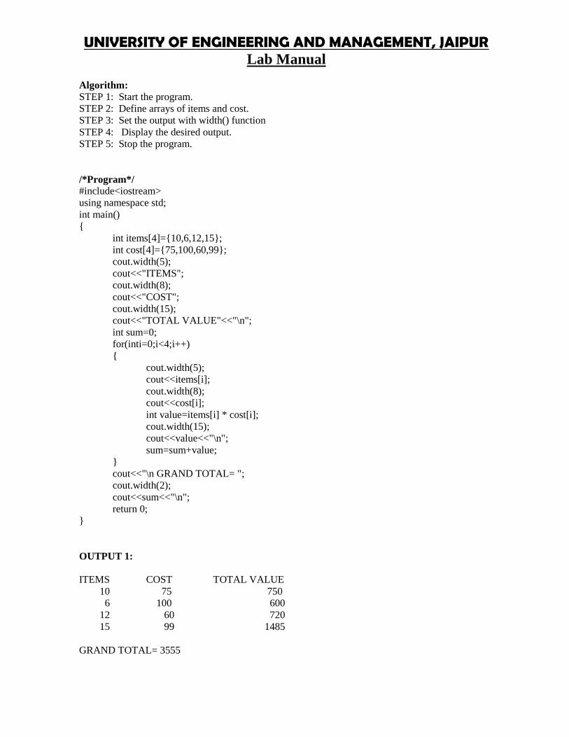
UNIVERSITY OF ENGINEERING AND MANAGEMENT, JAIPURLab Manual
Dept. of Computer Science and Engineering, UEM Jaipur
Algorithm:STEP 1: Start the program.STEP 2: Define arrays of items and cost.STEP 3: Set the output with width() functionSTEP 4: Display the desired output.STEP 5: Stop the program.
/*Program*/#include<iostream>using namespace std;int main(){
int items[4]={10,6,12,15};int cost[4]={75,100,60,99};cout.width(5);cout<<"ITEMS";cout.width(8);cout<<"COST";cout.width(15);cout<<"TOTAL VALUE"<<"\n";int sum=0;for(inti=0;i<4;i++){
cout.width(5);cout<<items[i];cout.width(8);cout<<cost[i];int value=items[i] * cost[i];cout.width(15);cout<<value<<"\n";sum=sum+value;
}cout<<"\n GRAND TOTAL= ";cout.width(2);cout<<sum<<"\n";return 0;
}
OUTPUT 1:
ITEMS COST TOTAL VALUE10 75 750
6 100 60012 60 72015 99 1485
GRAND TOTAL= 3555

UNIVERSITY OF ENGINEERING & MANAGEMENT, JAIPURLab Manual
Dept. of Computer Science and Engineering, UEM Jaipur
Experiment No. 15:CONSOLE INPUT OUTPUTAim: Write a C++ program where you find the square root of any five values. Format thedesired output with precision() function.
Description:By using precision () function we just format the output. This function is used to set number ofdecimal points to a float value.
Algorithm:STEP 1: Start the program.STEP 2: Set precision.STEP 3: Set the width of output and find the square root of particular values.STEP 4: Display the desired output.STEP 5: Stop the program.
/*Program*/#include<iostream>#include<cmath>using namespace std;int main(){ cout<<"precision set to 3 digits \n\n";
cout.precision(3);cout.width(10);cout<<"VALUE";cout.width(15);cout<<"SORT_OF_VALUE"<<"\n";for(int n=1;n<=5;n++){
cout.width(8);cout<<n;cout.width(13);cout<<sqrt(n)<<"\n";
}cout<<"\n PRECISION SET TO 5 DIGITS \n\n";cout.precision(5);cout<<"sqrt(10)= "<<sqrt(10)<<"\n\n";cout.precision(0);cout<<"sqrt(10)= "<<sqrt(10)<<"\n default settings \n";return 0;
}
OUTPUT:precision set to 3 digits
VALUE SORT_OF_VALUE1 12 1.413 1.734 25 2.24
PRECISION SET TO 5 DIGITS
sqrt(10)= 3.1623sqrt(10)= 3default settings

UNIVERSITY OF ENGINEERING AND MANAGEMENT, JAIPURLab Manual
Dept. of Computer Science and Engineering, UEM Jaipur
Experiment No. 16:CONSOLE INPUT OUTPUTAim: Fill the blank spaces of the above program with ‘.’
Description:By using fill () function we just format the output. The blank spaces of the above output is replacedby ‘.’
Algorithm:STEP 1: Start the program.STEP 2: Set precision.STEP 3: Set the width of output and find the square root of particular values.STEP 4: Fill up the blank spaces with ‘.’ Using fill() function.STEP 5: Display the desired output.STEP 6: Stop the program.
/*Program*/#include<iostream>#include<cmath>using namespace std;int main(){
cout<<"precision set to 3 digits \n\n";cout.precision(3);cout.fill('.');cout.width(10);cout<<"VALUE";cout.width(15);cout<<"SORT_OF_VALUE"<<"\n";for(int n=1;n<=5;n++){
cout.width(8);cout<<n;cout.width(13);cout<<sqrt(n)<<"\n";
}cout<<"\n PRECISION SET TO 5 DIGITS \n\n";cout.precision(5);cout<<"sqrt(10)= "<<sqrt(10)<<"\n\n";cout.precision(0);cout<<"sqrt(10)"<<sqrt(10)<<"default setting \n";return 0;
}
OUTPUT:precision set to 3 digits
……….VALUE………… SORT_OF_VALUE……………..1……………………………1……...……...2………………………...1.41……………..3…………………...……1.73……………..4……………………………2……………..5…………………………2.24PRECISION SET TO 5 DIGITS
sqrt(10)= 3.1623

UNIVERSITY OF ENGINEERING & MANAGEMENT, JAIPURLab Manual
Dept. of Computer Science and Engineering, UEM Jaipur
sqrt(10)= 3default settings
Experiment No. 17:FILE HANDLINGAim: Write a Program for Read File Operation Using C++ Programming
Description:File handling concept in C++ language is used for store a data permanently in computer. Using filehandling we can store our data in Secondary memory (Hard disk). fstream is used to both read andwrite data from/to files
Algorithm:STEP 1: Start the program.STEP 2: Declare the variables.STEP 3: Get the file name to read.STEP 4: Using ifstreamin(filename) check whether the file exist.STEP 5: If the file exist then check for the end of file condition.STEP 6: Read the contents of the file.STEP 7: Print the contents of the file.STEP 8: Stop the program.
/*Program*/#include<iostream>#include<fstream>using namespace std;int main(){
char c,fname[10];cout<<"Enter file name:";cin>>fname;ifstream in(fname);
if(!in){
cout<<"File Does not Exist";return;
}cout<<"\n\n";
while(in.eof()==0){
in.get(c);cout<<c;
}
}
OUTPUT:Enter File name: one.txtINDIA
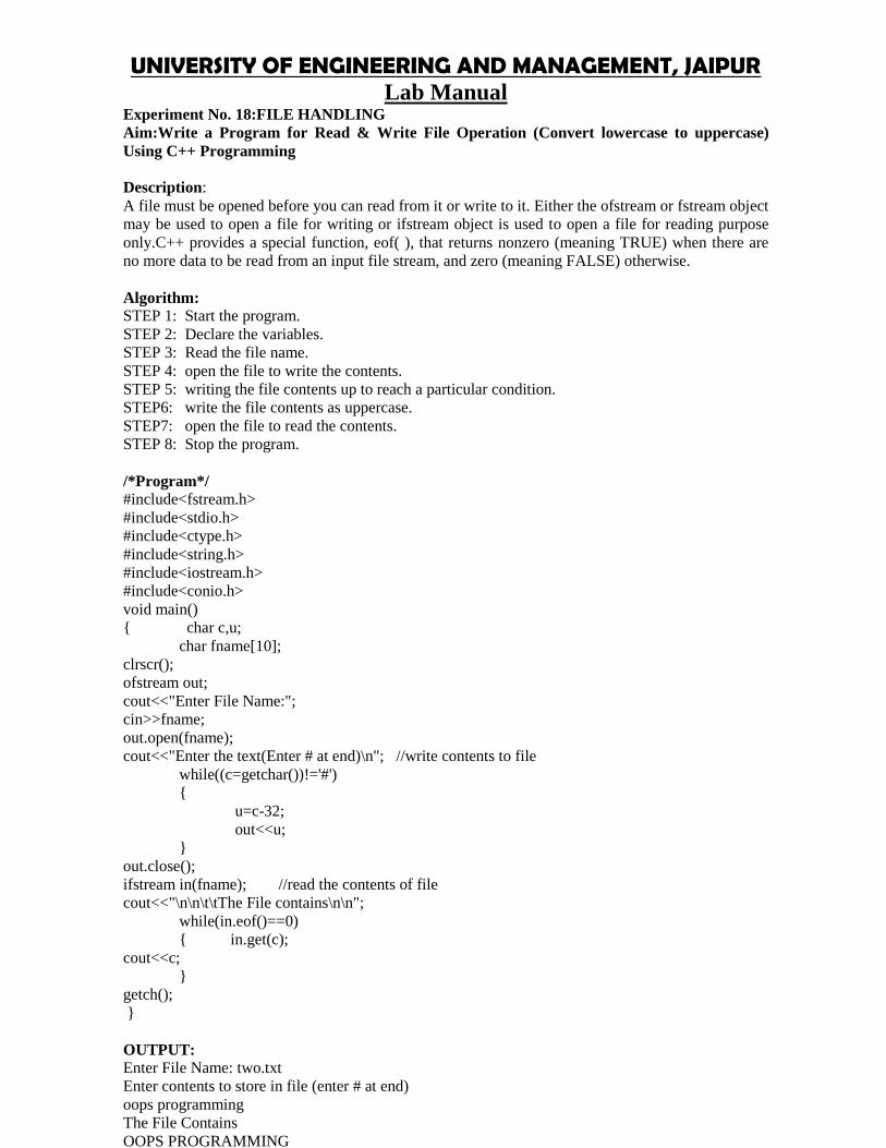
UNIVERSITY OF ENGINEERING AND MANAGEMENT, JAIPURLab Manual
Dept. of Computer Science and Engineering, UEM Jaipur
Experiment No. 18:FILE HANDLINGAim:Write a Program for Read & Write File Operation (Convert lowercase to uppercase)Using C++ Programming
Description:A file must be opened before you can read from it or write to it. Either the ofstream or fstream objectmay be used to open a file for writing or ifstream object is used to open a file for reading purposeonly.C++ provides a special function, eof( ), that returns nonzero (meaning TRUE) when there areno more data to be read from an input file stream, and zero (meaning FALSE) otherwise.
Algorithm:STEP 1: Start the program.STEP 2: Declare the variables.STEP 3: Read the file name.STEP 4: open the file to write the contents.STEP 5: writing the file contents up to reach a particular condition.STEP6: write the file contents as uppercase.STEP7: open the file to read the contents.STEP 8: Stop the program.
/*Program*/#include<fstream.h>#include<stdio.h>#include<ctype.h>#include<string.h>#include<iostream.h>#include<conio.h>void main(){ char c,u;
char fname[10];clrscr();ofstream out;cout<<"Enter File Name:";cin>>fname;out.open(fname);cout<<"Enter the text(Enter # at end)\n"; //write contents to file
while((c=getchar())!='#'){
u=c-32;out<<u;
}out.close();ifstream in(fname); //read the contents of filecout<<"\n\n\t\tThe File contains\n\n";
while(in.eof()==0){ in.get(c);
cout<<c;}
getch();}
OUTPUT:Enter File Name: two.txtEnter contents to store in file (enter # at end)oops programmingThe File ContainsOOPS PROGRAMMING
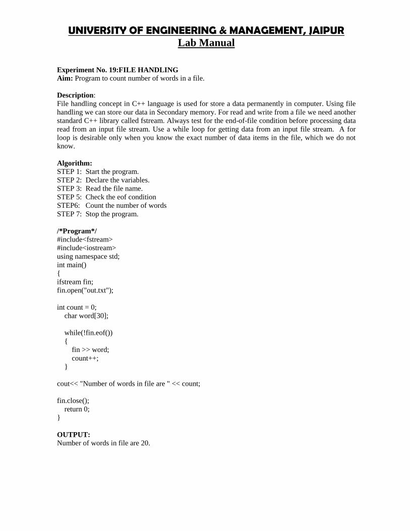
UNIVERSITY OF ENGINEERING & MANAGEMENT, JAIPURLab Manual
Dept. of Computer Science and Engineering, UEM Jaipur
Experiment No. 19:FILE HANDLINGAim: Program to count number of words in a file.
Description:File handling concept in C++ language is used for store a data permanently in computer. Using filehandling we can store our data in Secondary memory. For read and write from a file we need anotherstandard C++ library called fstream. Always test for the end-of-file condition before processing dataread from an input file stream. Use a while loop for getting data from an input file stream. A forloop is desirable only when you know the exact number of data items in the file, which we do notknow.
Algorithm:STEP 1: Start the program.STEP 2: Declare the variables.STEP 3: Read the file name.STEP 5: Check the eof conditionSTEP6: Count the number of wordsSTEP 7: Stop the program.
/*Program*/#include<fstream>#include<iostream>using namespace std;int main(){ifstream fin;fin.open("out.txt");
int count = 0;char word[30];
while(!fin.eof()){
fin >> word;count++;
}
cout<< "Number of words in file are " << count;
fin.close();return 0;
}
OUTPUT:Number of words in file are 20.

UNIVERSITY OF ENGINEERING AND MANAGEMENT, JAIPURLab Manual
Dept. of Computer Science and Engineering, UEM Jaipur
Experiment No. 20:FILE HANDLINGAim:Program to count number of lines in a text file.
Description:File handling concept in C++ language is used for store a data permanently in computer. Using filehandling we can store our data in Secondary memory. For read and write from a file we need anotherstandard C++ library called fstream. Always test for the end-of-file condition before processing dataread from an input file stream. Use a while loop for getting data from an input file stream. A forloop is desirable only when you know the exact number of data items in the file, which we do notknow.
Algorithm:STEP 1: Start the program.STEP 2: Declare the variables.STEP 3: Read the file name.STEP 5: Check the eof conditionSTEP 6: Count the number of linesSTEP 7: Stop the program.
/*Program*/#include<fstream>#include<iostream>using namespace std;int main(){ifstream fin;fin.open("out.txt");
int count = 0;char str[80];
while(!fin.eof()){
fin.getline(str,80);count++;
}cout<< "Number of lines in file are " << count;fin.close();
return 0;}
OUTPUT:Number of lines in file are 5.

UNIVERSITY OF ENGINEERING & MANAGEMENT, JAIPURLab Manual
Dept. of Computer Science and Engineering, UEM Jaipur
Experiment No. 21:FILE HANDLINGAim:Program to implement searching operation on binary file in C++
Description:When data is stored in a file in the binary format, reading and writingdata is faster because no time islost in converting the data from one format to another format. Such files are called binary files. Thisfollowing program explains how to create binary files and also how to read, write, search, delete andmodify data from binary files.
Algorithm:STEP 1: Start the program.STEP 2: Declare the variables and functions with definitions.STEP 3: Read the file name.STEP 5: Check the eof conditionSTEP 6: searching is done.STEP 7: Stop the program.
/*Program*/#include<fstream.h>#include<conio.h>#include<stdlib.h>class student{
introllno;char name[20];char branch[3];float marks;char grade;public:
void getdata(){
cout<<"Rollno: ";cin>>rollno;cout<<"Name: ";cin>>name;cout<<"Branch: ";cin>>branch;cout<<"Marks: ";cin>>marks;
if(marks>=75){
grade = 'A';}else if(marks>=60){
grade = 'B';}else if(marks>=50){
grade = 'C';}else if(marks>=40){
grade = 'D';}else

UNIVERSITY OF ENGINEERING AND MANAGEMENT, JAIPURLab Manual
Dept. of Computer Science and Engineering, UEM Jaipur
{grade = 'F';
}}void putdata(){
cout<<"Rollno: "<<rollno<<"\tName: "<<name<<"\n";cout<<"Marks: "<<marks<<"\tGrade: "<<grade<<"\n";
}intgetrno(){
return rollno;}
}stud1;void main(){
clrscr();
fstreamfio("marks.dat", ios::in | ios::out);char ans='y';while(ans=='y' || ans=='Y'){
stud1.getdata();fio.write((char *)&stud1, sizeof(stud1));cout<<"Record added to the file\n";cout<<"\nWant to enter more ? (y/n)..";cin>>ans;
}clrscr();intrno;long pos;char found='f';cout<<"Enter rollno of student to be search for: ";cin>>rno;fio.seekg(0);while(!fio.eof()){
pos=fio.tellg();fio.read((char *)&stud1, sizeof(stud1));if(stud1.getrno() == rno){
stud1.putdata();fio.seekg(pos);found='t';break;
}}if(found=='f'){
cout<<"\nRecord not found in the file..!!\n";cout<<"Press any key to exit...\n";getch();exit(2);
}fio.close();getch();}

UNIVERSITY OF ENGINEERING & MANAGEMENT, JAIPURLab Manual
Dept. of Computer Science and Engineering, UEM Jaipur
OUTPUT:Rollno: 1Name: AmanBranch: CSEMarks: 96Recorded added to the file
Want to enter more? (y/n)..yRollno: 2Name: SavvyBranch: ITMarks: 91Recorded added to the file
Want to enter more? (y/n)..n
SearchingEnterrollno of student to be search for: 2Rollno: 2 Name: SavvyMarks: 91 Grade: A
Experiment No. 22:STLAim:C++ Program to Implement Queue in STL.
Description:The C++ STL (Standard Template Library) is a powerful set of C++ template classes to providegeneral-purpose templatized classes and functions that implement many popular and commonly usedalgorithms and data structures like vectors, lists, queues, and stacks.This C++ Program demonstratesimplementation of Queue in STL. Here is source code of the C++ Program to demonstrate Queue inSTL.
Algorithm:STEP 1: Start the program.STEP 2: Declare the variables and functions with definitions.STEP 3: Define STL of queueSTEP 5: Doing queue operationsSTEP 6: Stop the program.
/*Program*/#include <iostream>#include <queue>#include <string>#include <cstdlib>using namespace std;int main(){
queue<int> q;int choice, item;
while (1){
cout<<"\n---------------------"<<endl;cout<<"Queue Implementation in Stl"<<endl;cout<<"\n---------------------"<<endl;cout<<"1.Insert Element into the Queue"<<endl;cout<<"2.Delete Element from the Queue"<<endl;

UNIVERSITY OF ENGINEERING AND MANAGEMENT, JAIPURLab Manual
Dept. of Computer Science and Engineering, UEM Jaipur
cout<<"3.Size of the Queue"<<endl;cout<<"4.Front Element of the Queue"<<endl;cout<<"5.Last Element of the Queue"<<endl;cout<<"6.Exit"<<endl;cout<<"Enter your Choice: ";cin>>choice;
switch(choice){case 1:
cout<<"Enter value to be inserted: ";cin>>item;q.push(item);
break;case 2:
item = q.front();q.pop();cout<<"Element "<<item<<" Deleted"<<endl;
break;case 3:
cout<<"Size of the Queue: ";cout<<q.size()<<endl;
break;case 4:
cout<<"Front Element of the Queue: ";cout<<q.front()<<endl;
break;case 5:
cout<<"Back Element of the Queue: ";cout<<q.back()<<endl;
break;case 6:
exit(1);break;
default:cout<<"Wrong Choice"<<endl;
}}return 0;
}
OUTPUT:1.Insert Element into the Queue2.Delete Element from the Queue3.Size of the Queue4.Front Element of the Queue5.Last Element of the Queue6.ExitEnter your Choice: 1Enter value to be inserted: 9
---------------------Queue Implementation in Stl
---------------------1.Insert Element into the Queue2.Delete Element from the Queue3.Size of the Queue

UNIVERSITY OF ENGINEERING & MANAGEMENT, JAIPURLab Manual
Dept. of Computer Science and Engineering, UEM Jaipur
4.Front Element of the Queue5.Last Element of the Queue6.ExitEnter your Choice: 1Enter value to be inserted: 8---------------------Queue Implementation in Stl
---------------------1.Insert Element into the Queue2.Delete Element from the Queue3.Size of the Queue4.Front Element of the Queue5.Last Element of the Queue6.ExitEnter your Choice: 3Size of the Queue: 2
Experiment No. 23:STLAim:C++ Program to Implement Vector in STL
Description:Vector is a template class that is a perfect replacement for the good old C-style arrays. It allows thesame natural syntax that is used with plain arrays but offers a series of services that free the C++programmer from taking care of the allocated memory and help operating consistently on thecontained objects.This C++ Program demonstrates implementation of Vector in STL.Here is sourcecode of the C++ Program to demonstrate Vector in STL.
Algorithm:STEP 1: Start the program.STEP 2: Declare the variables and functions with definitions.STEP 3: Define STL of vectorSTEP 5: Doing vector operationsSTEP 6: Stop the program.
/*Program*/#include <iostream>#include <vector>#include <string>#include <cstdlib>using namespace std;int main(){
vector<int>ss;vector<int>::iterator it;
int choice, item;while (1){
cout<<"\n---------------------"<<endl;cout<<"Vector Implementation in Stl"<<endl;cout<<"\n---------------------"<<endl;cout<<"1.Insert Element into the Vector"<<endl;cout<<"2.Delete Last Element of the Vector"<<endl;

UNIVERSITY OF ENGINEERING AND MANAGEMENT, JAIPURLab Manual
Dept. of Computer Science and Engineering, UEM Jaipur
cout<<"3.Size of the Vector"<<endl;cout<<"4.Display by Index"<<endl;cout<<"5.Dislplay by Iterator"<<endl;cout<<"6.Clear the Vector"<<endl;cout<<"7.Exit"<<endl;cout<<"Enter your Choice: ";cin>>choice;
switch(choice){case 1:
cout<<"Enter value to be inserted: ";cin>>item;ss.push_back(item);
break;case 2:
cout<<"Delete Last Element Inserted:"<<endl;ss.pop_back();
break;case 3:
cout<<"Size of Vector: ";cout<<ss.size()<<endl;
break;case 4:
cout<<"Displaying Vector by Index: ";for (inti = 0; i<ss.size(); i++){
cout<<ss[i]<<" ";}
cout<<endl;break;
case 5:cout<<"Displaying Vector by Iterator: ";
for (it = ss.begin(); it != ss.end(); it++){
cout<<*it<<" ";}
cout<<endl;break;
case 6:ss.clear();cout<<"Vector Cleared"<<endl;
break;case 7:
exit(1);break;
default:cout<<"Wrong Choice"<<endl;
}}return 0;
}

UNIVERSITY OF ENGINEERING & MANAGEMENT, JAIPURLab Manual
Dept. of Computer Science and Engineering, UEM Jaipur
OUTPUT:---------------------Vector Implementation in Stl
---------------------1.Insert Element into the Vector2.Delete Last Element of the Vector3.Size of the Vector4.Display by Index5.Dislplay by Iterator6.Clear the Vector7.ExitEnter your Choice: 1Enter value to be inserted: 4
---------------------Vector Implementation in Stl
---------------------1.Insert Element into the Vector2.Delete Last Element of the Vector3.Size of the Vector4.Display by Index5.Dislplay by Iterator6.Clear the Vector7.ExitEnter your Choice: 1Enter value to be inserted: 6
---------------------Vector Implementation in Stl
---------------------1.Insert Element into the Vector2.Delete Last Element of the Vector3.Size of the Vector4.Display by Index5.Dislplay by Iterator6.Clear the Vector7.ExitEnter your Choice: 1Enter value to be inserted: 3
---------------------Vector Implementation in Stl
---------------------1.Insert Element into the Vector2.Delete Last Element of the Vector3.Size of the Vector4.Display by Index5.Dislplay by Iterator6.Clear the Vector7.ExitEnter your Choice: 1Enter value to be inserted: 8

UNIVERSITY OF ENGINEERING AND MANAGEMENT, JAIPURLab Manual
Dept. of Computer Science and Engineering, UEM Jaipur
---------------------Vector Implementation in Stl
---------------------1.Insert Element into the Vector2.Delete Last Element of the Vector3.Size of the Vector4.Display by Index5.Dislplay by Iterator6.Clear the Vector7.ExitEnter your Choice: 1Enter value to be inserted: 9
---------------------Vector Implementation in Stl
---------------------1.Insert Element into the Vector2.Delete Last Element of the Vector3.Size of the Vector4.Display by Index5.Dislplay by Iterator6.Clear the Vector7.ExitEnter your Choice: 1Enter value to be inserted: 2
---------------------Vector Implementation in Stl
---------------------1.Insert Element into the Vector2.Delete Last Element of the Vector3.Size of the Vector4.Display by Index5.Dislplay by Iterator6.Clear the Vector7.ExitEnter your Choice: 3Size of Vector: 6
---------------------Vector Implementation in Stl
---------------------1.Insert Element into the Vector2.Delete Last Element of the Vector3.Size of the Vector4.Display by Index5.Dislplay by Iterator6.Clear the Vector7.ExitEnter your Choice: 4Displaying Vector by Index: 4 6 3 8 9 2
---------------------

UNIVERSITY OF ENGINEERING & MANAGEMENT, JAIPURLab Manual
Dept. of Computer Science and Engineering, UEM Jaipur
Vector Implementation in Stl
---------------------1.Insert Element into the Vector2.Delete Last Element of the Vector3.Size of the Vector4.Display by Index5.Dislplay by Iterator6.Clear the Vector7.ExitEnter your Choice: 2Delete Last Element Inserted:
---------------------Vector Implementation in Stl
---------------------1.Insert Element into the Vector2.Delete Last Element of the Vector3.Size of the Vector4.Display by Index5.Dislplay by Iterator6.Clear the Vector7.ExitEnter your Choice: 3Size of Vector: 5
---------------------Vector Implementation in Stl
---------------------1.Insert Element into the Vector2.Delete Last Element of the Vector3.Size of the Vector4.Display by Index5.Dislplay by Iterator6.Clear the Vector7.ExitEnter your Choice: 5Displaying Vector by Iterator: 4 6 3 8 9

UNIVERSITY OF ENGINEERING AND MANAGEMENT, JAIPURLab Manual
Dept. of Computer Science and Engineering, UEM Jaipur
Experiment No. 24:STLAim:C++ Program to Implement Set in STL
Description:This C++ Program demonstrates implementation of Set in STL.Here is source code of the C++Program to demonstrate Set in STL.
Algorithm:STEP 1: Start the program.STEP 2: Declare the variables and functions with definitions.STEP 3: Define STL of setSTEP 5: Doing set operationsSTEP 6: Stop the program.
/*Program*/#include <iostream>#include <set>#include <string>#include <cstdlib>using namespace std;int main(){
set<int>st;set<int>::iterator it;
int choice, item;while (1){
cout<<"\n---------------------"<<endl;cout<<"Set Implementation in Stl"<<endl;cout<<"\n---------------------"<<endl;cout<<"1.Insert Element into the Set"<<endl;cout<<"2.Delete Element of the Set"<<endl;cout<<"3.Size of the Set"<<endl;cout<<"4.Find Element in a Set"<<endl;cout<<"5.Dislplay by Iterator"<<endl;cout<<"6.Exit"<<endl;cout<<"Enter your Choice: ";cin>>choice;
switch(choice){case 1:
cout<<"Enter value to be inserted: ";cin>>item;st.insert(item);
break;case 2:
cout<<"Enter the element to be deleted: ";cin>>item;st.erase(item);
break;case 3:
cout<<"Size of the Set: ";cout<<st.size()<<endl;
break;case 4:
cout<<"Enter the element to be found: ";cin>>item;

UNIVERSITY OF ENGINEERING & MANAGEMENT, JAIPURLab Manual
Dept. of Computer Science and Engineering, UEM Jaipur
it = st.find(item);if (it != st.end())
cout<<"Element "<<*it<<" found in the set" <<endl;else
cout<<"No Element Found"<<endl;break;
case 5:cout<<"Displaying Map by Iterator: ";
for (it = st.begin(); it != st.end(); it++){
cout<< (*it)<<" ";}
cout<<endl;break;
case 6:exit(1);
break;default:
cout<<"Wrong Choice"<<endl;}
}return 0;
}
OUTPUT:---------------------Set Implementation in Stl---------------------
1.Insert Element into the Set2.Delete Element of the Set3.Size of the Set4.Find Element in a Set5.Dislplay by Iterator6.ExitEnter your Choice: 1Enter value to be inserted: 1
---------------------Set Implementation in Stl---------------------
1.Insert Element into the Set2.Delete Element of the Set3.Size of the Set4.Find Element in a Set5.Dislplay by Iterator6.ExitEnter your Choice: 1Enter value to be inserted: 2
---------------------Set Implementation in Stl---------------------
1.Insert Element into the Set2.Delete Element of the Set3.Size of the Set4.Find Element in a Set5.Dislplay by Iterator

UNIVERSITY OF ENGINEERING AND MANAGEMENT, JAIPURLab Manual
Dept. of Computer Science and Engineering, UEM Jaipur
6.ExitEnter your Choice: 1Enter value to be inserted: 3
---------------------Set Implementation in Stl---------------------
1.Insert Element into the Set2.Delete Element of the Set3.Size of the Set4.Find Element in a Set5.Dislplay by Iterator6.ExitEnter your Choice: 1Enter value to be inserted: 4
---------------------Set Implementation in Stl---------------------
1.Insert Element into the Set2.Delete Element of the Set3.Size of the Set4.Find Element in a Set5.Dislplay by Iterator6.ExitEnter your Choice: 1Enter value to be inserted: 5
---------------------Set Implementation in Stl---------------------
1.Insert Element into the Set2.Delete Element of the Set3.Size of the Set4.Find Element in a Set5.Dislplay by Iterator6.ExitEnter your Choice: 1Enter value to be inserted: 4
---------------------Set Implementation in Stl---------------------
1.Insert Element into the Set2.Delete Element of the Set3.Size of the Set4.Find Element in a Set5.Dislplay by Iterator6.ExitEnter your Choice: 1Enter value to be inserted: 3
---------------------Set Implementation in Stl---------------------
1.Insert Element into the Set2.Delete Element of the Set

UNIVERSITY OF ENGINEERING & MANAGEMENT, JAIPURLab Manual
Dept. of Computer Science and Engineering, UEM Jaipur
3.Size of the Set4.Find Element in a Set5.Dislplay by Iterator6.ExitEnter your Choice: 1Enter value to be inserted: 2
---------------------Set Implementation in Stl---------------------
1.Insert Element into the Set2.Delete Element of the Set3.Size of the Set4.Find Element in a Set5.Dislplay by Iterator6.ExitEnter your Choice: 1Enter value to be inserted: 1
---------------------Set Implementation in Stl---------------------
1.Insert Element into the Set2.Delete Element of the Set3.Size of the Set4.Find Element in a Set5.Dislplay by Iterator6.ExitEnter your Choice: 3Size of the Set: 5
---------------------Set Implementation in Stl---------------------
1.Insert Element into the Set2.Delete Element of the Set3.Size of the Set4.Find Element in a Set5.Dislplay by Iterator6.ExitEnter your Choice: 5Displaying Map by Iterator: 1 2 3 4 5
---------------------Set Implementation in Stl---------------------
1.Insert Element into the Set2.Delete Element of the Set3.Size of the Set4.Find Element in a Set5.Dislplay by Iterator6.ExitEnter your Choice: 4Enter the element to be found: 3Element 3 found in the set

UNIVERSITY OF ENGINEERING AND MANAGEMENT, JAIPURLab Manual
Dept. of Computer Science and Engineering, UEM Jaipur
---------------------Set Implementation in Stl---------------------
1.Insert Element into the Set2.Delete Element of the Set3.Size of the Set4.Find Element in a Set5.Dislplay by Iterator6.ExitEnter your Choice: 2Enter the element to be deleted: 5
Experiment No. 25:String ManipulationAim:Write a C++ program to copy a string from another string. Also concatenate them and find thetotal length after concatenation.
Description:C++ provides following two types of string representations:-The C-style character string.-The string class type introduced with Standard C++.The C-style character string originated within the C language and continues to be supported withinC++. This string is actually a one-dimensional array of characters which is terminated by a nullcharacter '\0'. Thus a null-terminated string contains the characters that comprise the string followedby a null.C++ supports a wide range of functions that manipulate null-terminated strings:strcpy(s1, s2);Copies string s2 into string s1.strcat(s1, s2);Concatenates string s2 onto the end of string s1.strlen(s1);Returns the length of string s1.strcmp(s1, s2);Returns 0 if s1 and s2 are the same; less than 0 if s1<s2; greater than 0 if s1>s2.strchr(s1, ch);Returns a pointer to the first occurrence of character ch in string s1.strstr(s1, s2);Returns a pointer to the first occurrence of string s2 in string s1.
Algorithm:STEP 1: Start the program.STEP 2: Declare the string variables.STEP 3: Copy the content of str1 to str3STEP 5: Concatenate str1 and str2STEP 6: Find the length of str1STEP 7: Stop the program.
/*Program*/#include <iostream>#include <cstring>using namespace std;int main (){
char str1[10] = "Hello";char str2[10] = "World";char str3[10];
intlen ;

UNIVERSITY OF ENGINEERING & MANAGEMENT, JAIPURLab Manual
Dept. of Computer Science and Engineering, UEM Jaipur
// copy str1 into str3strcpy( str3, str1);cout<< "strcpy( str3, str1) : " << str3 <<endl;
// concatenates str1 and str2strcat( str1, str2);cout<< "strcat( str1, str2): " << str1 <<endl;
// total lenghth of str1 after concatenationlen = strlen(str1);cout<< "strlen(str1) : " <<len<<endl;
return 0;}OUTPUT:strcpy( str3, str1) : Hellostrcat( str1, str2): HelloWorldstrlen(str1) : 10
Experiment No. 26:String ManipulationAim:Write a C++ program to implement he String Class in C++.
Description:The standard C++ library provides a string class type that supports all the operations mentionedabove, additionally much more functionality.
Algorithm:STEP 1: Start the program.STEP 2: Declare the string variables.STEP 3: Copy str1 into str3STEP 5: Concatenate str1 and str2 and stores into str3STEP 6: Find the length of str3STEP 7: Stop the program.
/*Program*/#include <iostream>#include <string>using namespace std;int main (){
string str1 = "Hello";string str2 = "World";string str3;
intlen ;
// copy str1 into str3str3 = str1;
cout<< "str3 : " << str3 <<endl;
// concatenates str1 and str2str3 = str1 + str2;
cout<< "str1 + str2 : " << str3 <<endl;
// total length of str3 after concatenation

UNIVERSITY OF ENGINEERING AND MANAGEMENT, JAIPURLab Manual
Dept. of Computer Science and Engineering, UEM Jaipur
len = str3.size();cout<< "str3.size() : " <<len<<endl;
return 0;}
OUTPUT:str3 : Hellostr1 + str2 : HelloWorldstr3.size() : 10

UNIVERSITY OF ENGINEERING & MANAGEMENT, JAIPURLab Manual
Title of Course: Computer Organization LabCourse Code: EE594BL-T-P Scheme: 0-0-3 Course Credits: 2
Objective:1. Understand the architecture of a modern computer with its various processing units.2. To learn and understand IC of basic gates.3. To provide an efficient understanding of the Hardware, design complete circuit.
Learning Outcomes: The students will have a detailed knowledge of the concept of IC1. Students can understand the architecture of modern computer.2. They can analyze the Performance of a computer using performance equation3. Students can calculate the effective address of an operand by addressing modes4. They can understand how computer stores positive and negative numbers.5. Understanding of how a computer performs arithmetic operation of positive and negativenumbers.6. Understanding of how computer stores floating point numbers in IEEE 754 standard.7. Students can understand how cache mapping occurs in computer and can solve variousproblems related to this.8. Secondary storage organization and problem solving
Course Contents:Unit –I: Basic gatesStudy about logic gates and verify their truth tables. XOR ( IC 7486), OR (IC 7432),NOT (IC7404), AND (IC 7408),NAND (IC 7400), etc. Also implementation basic gates using universalgate (NAND).
Unit –II: Half adder, Full AdderImplement Half and Full Adder using basic gates and check with the following truth table. HalfAdder and Full Adder circuits is explained with their truth tables in this article. Design of FullAdder using Half Adder circuit is also shown. Single-bit Full Adder circuit and Multi-bitaddition using Full Adder
Unit –III: Half Substractor, Full Substractor.Implement Half and Full Adder using basic gates and check with the following truth table. HalfSubtractor is used for subtracting one single bit binary digit from another single bit binary digit.Full Subtractor, A logic Circuit Which is used for Subtracting Three Single bit Binary digit isknown as Full Subtractor
Unit –IV: 4-bit parallel Binary adder and substractor.The arithmetic addition of two binary digits, together with an input carry from a previous stage.The serial addition method uses only one full-adder circuit and a storage device to hold thegenerated output carry and sum.
Unit –V: BCD adder

UNIVERSITY OF ENGINEERING & MANAGEMENT, JAIPURLab Manual
The arithmetic addition of two decimal digits in BCD, together with an input carry from aprevious stage. Since each input digit does not exceed 9, the output sum cannot be greater than19, the 1 in the sum being an input carry.
Unit –VI: 8 to 1 Multiplexer unit (MUX)It transfer a large number of information units over a smaller number of channels, (usually onechannel) under the control of selection signals. Multiplexer means many to one. A multiplexer isa circuit with many inputs but only one output.
Unit –VII: DEMULTIPLEXERIt perform the opposite function of multiplexers.
Unit –VIII: BCD to 7 segment decoderUsing digital kit implement Digital number (0,1,2,3,4,5,6,7,8,9)
Unit –IX: BCD TO EXCESS 3CODE CONVERTOR
The excess-3 code digit is obtained by adding three to the corresponding BCD digit.
Unit –X: FLIP FLOPS-R Flip Flop, J-K Flip Flop, T Flip Flop, T Flip Flop
Unit –X: Design a composite ALU.
Implement Airthmatic Logic Unit Arithmetic operations are like addition ,substraction,multiplication, and division. Logical operations are like and, or nand, nor ,not operations on bits
Text Book:1. David A. Patterson, John L. Hennessy, “Computer Organization and Design”, Elsevier.
References:1. S.Salivahanan & S.Arivazhagan, “Digital Circuits and Design”, VIKAS publishing housePVT LTD
Recommended Systems/ Software Requrements:1. Trainer kit2. IC (Integrated Circuit)3. Wire/ Probes

UNIVERSITY OF ENGINEERING & MANAGEMENT, JAIPURLab Manual
LIST OF EXPERIMENTS
1. Realization of the basic gates (AND, OR, NOT) and universal gates (NAND, NOR).
2. Design and implementation of basic gates using universal gate (NAND).
3. Design and implementation of half adder.
4. Design and implementation of full adder.
5. Design and implementation of half substractor.
6. Design and implementation of full substractor.
7. Design of a 4-bit parallel Binary adder circuit using the IC-Chip 7483.
8. Design of an Adder/Subtractor composite unit circuit using the IC-Chip 7483.
9. Design a BCD adder using two 7483 IC chip.
10. Design an 8 to 1 Multiplexer unit (MUX) using basic gates and using IC 74151
11. Design an 8 to 1 Multiplexer unit (MUX) using basic gates and using IC 74153.
12. Design and implementation of DEMULTIPLEXER .
13. Design of a BCD to 7 segment decoder.
14. Design and implementation of BCD TO EXCESS 3CODE CONVERTOR
15. Design and implementation of SR LATCH ,SR FLIP FLOP AND JK FLIP FLOP.
16. Use a multiplexer unit to design a composite ALU.

UNIVERSITY OF ENGINEERING & MANAGEMENT, JAIPURLab Manual
EXPERIMENT NO.-1
AIM:- To study about logic gates and verify their truth tables.
APPARATUS REQUIRED: IC 7486, IC 7432, IC 7408, IC 7400, etc.
THEORY:
Circuit that takes the logical decision and the process are called logic gates. Each gate has one or more
input and only one output. OR, AND and NOT are basic gates. NAND, NOR and X-OR are known as
universal gates. Basic gates form these gates.
AND GATE:
The AND gate performs a logical multiplication commonly known as AND function. IC 7408 The output
is high when both the inputs are high. The output is low level when any one of the inputs is low.
OR GATE:
The OR gate performs a logical addition commonly known as OR function. IC 7432. The output is high
when any one of the inputs is high. The output is low level when both the inputs are low.
NOT GATE:
The NOT gate is called an inverter. IC 7404 The output is high when the input is low. The output is low
when the input is high.
NAND GATE:
The NAND gate is a contraction of AND-NOT. IC 7400. The output is high when both inputs are low and
any one of the input is low .The output is low level when both inputs are high.
NOR GATE:
The NOR gate is a contraction of OR-NOT. IC7402. The output is high when both inputs are low. The
output is low when one or both inputs are high.
X-OR GATE:
The output is high when any one of the inputs is high. IC 7486 The output is low when both the inputs are
low and both the inputs are high.

UNIVERSITY OF ENGINEERING & MANAGEMENT, JAIPURLab Manual
LOGIC GATES SYMBOL TRUTH TABLE AND PIN DIAGRAM:
NOT GATE
OR GATE:
SYMBOL: PIN DIAGRAM:
NOR GATE:

UNIVERSITY OF ENGINEERING & MANAGEMENT, JAIPURLab Manual
AND GATE:
NAND GATE:
EX-OR GATE:
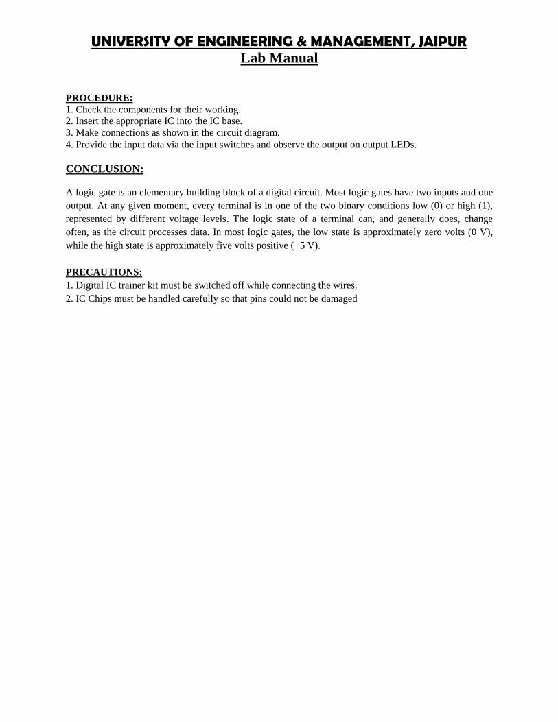
UNIVERSITY OF ENGINEERING & MANAGEMENT, JAIPURLab Manual
PROCEDURE:1. Check the components for their working.2. Insert the appropriate IC into the IC base.3. Make connections as shown in the circuit diagram.4. Provide the input data via the input switches and observe the output on output LEDs.
CONCLUSION:
A logic gate is an elementary building block of a digital circuit. Most logic gates have two inputs and oneoutput. At any given moment, every terminal is in one of the two binary conditions low (0) or high (1),represented by different voltage levels. The logic state of a terminal can, and generally does, changeoften, as the circuit processes data. In most logic gates, the low state is approximately zero volts (0 V),while the high state is approximately five volts positive (+5 V).
PRECAUTIONS:1. Digital IC trainer kit must be switched off while connecting the wires.2. IC Chips must be handled carefully so that pins could not be damaged

UNIVERSITY OF ENGINEERING & MANAGEMENT, JAIPURLab Manual
EXPERIMENT NO:2
AIM: Design and implementation of basic gates using universal gate (NAND).
APPRATUS REQUIRED: IC 7400
THEORY: The NAND Gate:
The NAND, which is composed of two or more inputs and a single output, is a very popular logic elementbecause it may be used as a universal function. That is, it may be employed to construct an inverter, anAND gate, an OR gate, or any combination of theses functions. The term NAND is formed by theconcatenation NOT-AND and implies an AND function with an inverted output. The standard symbol forthe NAND gate is shown in Figure 1-7 and its truth table listed in Table 1-4. The logical operation of theNAND gate is such that the output is LOW (0) only when all the inputs are HIGH (1).
PIN DIAGRAM:
Circuit Diagrams Truth Table
INPUT OUTPUTYA B
0 0 1
0 1 1
1 0 1
1 1 0

UNIVERSITY OF ENGINEERING & MANAGEMENT, JAIPURLab Manual
Not gate
Truth Table
AND gate
Truth Table
OR gate
INPUT OUTPUTYA B
0 0 0
0 1 1
1 0 1
INPUTA
OUTPUTY
0 1
1 0
INPUT OUTPUTYA B
0 0 0
0 1 0
1 0 0
1 1 1

UNIVERSITY OF ENGINEERING & MANAGEMENT, JAIPURLab Manual
Ex-OR gate
Ex-NOR gate
PROCEDURE:
1. Connect the logic gates as shown in the diagrams using IC 7400 NAND gate.
1 1 1
INPUT OUTPUTYA B
0 0 0
0 1 1
1 0 1
1 1 0
INPUT OUTPUTYA B
0 0 1
0 1 0
1 0 0
1 1 1

UNIVERSITY OF ENGINEERING & MANAGEMENT, JAIPURLab Manual
2. Feed the logic signals 0 or 1 from the logic input switches in different combinations at theinputs A & B.3. Monitor the output using logic output LED indicators.4. Repeat steps 1 to 3 for NOT, AND, OR, EX – OR & EX-NOR operations and compare theoutputs with the truth tables.
CONCLUSION:
A logic gate is an elementary building block of a digital circuit. Most logic gates have two inputs and oneoutput. At any given moment, every terminal is in one of the two binary conditions low (0) or high (1),represented by different voltage levels. The logic state of a terminal can, and generally does, changeoften, as the circuit processes data. In most logic gates, the low state is approximately zero volts (0 V),while the high state is approximately five volts positive (+5 V).
PRECAUTIONS:1. All the connections should be made properly.2. IC should not be reversed.

UNIVERSITY OF ENGINEERING & MANAGEMENT, JAIPURLab Manual
EXPERIMENT NO:3
AIM: Design and implementation of HALF ADDER.
APPRATUS REQUIRED: IC 7486, IC 7432, IC 7408, IC 7404, IC 7400, etc.
THEORY:
Half-Adder: A combinational logic circuit that performs the addition of two data bits, A and B, is calleda half-adder. Addition will result in two output bits; one of which is the sum bits, and the other is thecarry bit, C.
CIRCUIT DIAGRAM:
TRUTH TABLE:
Logical Expression:-= ̅ + = ⨁carry =
PROCEDURE:1. Check the components for their working.2. Insert the appropriate IC into the IC base.
Truth Table of a Half-AdderInputs Outputs
A BSum
SCarry
C0 0 0 00 1 1 01 0 1 01 1 0 1

UNIVERSITY OF ENGINEERING & MANAGEMENT, JAIPURLab Manual
3. Make connections as shown in the circuit diagram.4. Provide the input data via the input switches and observe the output on output LEDs.
CONCLUSION:
Thus, for example, a binary input of 101 results in an output of 1 + 0 + 1 = 10 (decimal number 2). Thecarry-out represents bit one of the result, while the sum represents bit zero. Likewise, a half adder can beused as a 2:2 lossy compressor, compressing four possible inputs into three possible outputs.
PRECAUTIONS:
1. Digital IC trainer kit must be switched off while connecting the wires.2. IC Chips must be handled carefully so that pins could not be damaged

UNIVERSITY OF ENGINEERING & MANAGEMENT, JAIPURLab Manual
EXPERIMENT NO:4
AIM: Design and implementation of FULL ADDER.
APPRATUS REQUIRED: IC 7486, IC 7432, IC 7408, IC 7404, IC 7400, etc.
THEORY:
Full-Adder: The half-adder does not take the carry bit from its previous stage into account. This carry bitfrom its previous stage is called carry-in bit. A combinational logic circuit that adds two data bits, A andB, and a carry-in bit, Cin , is called a full-adder.
CIRCUIT DIAGRAM:

UNIVERSITY OF ENGINEERING & MANAGEMENT, JAIPURLab Manual
TRUTH TABLE:
Truth Table of a Full-AdderInputs Outputs
Augend BitA
Addend BitB
Carry inputCin
SumS
CarryC
0 0 0 0 00 0 1 1 00 1 0 1 00 1 1 0 11 0 0 1 01 0 1 0 11 1 0 0 11 1 1 1 1
BOOLEAN EXPRESSIONS:S= A B CC=A B + B Cin + A Cin
PROCEDURE:1. Check the components for their working.2. Insert the appropriate IC into the IC base.3. Make connections as shown in the circuit diagram.4. Provide the input data via the input switches and observe the output on output LEDs.
CONCLUSION:Thus, for example, a binary input of 101 results in an output of 1 + 0 + 1 = 10 (decimal number 2). Thecarry-out represents bit one of the result, while the sum represents bit zero.
PRECAUTIONS:
1. Digital IC trainer kit must be switched off while connecting the wires.2. IC Chips must be handled carefully so that pins could not be damaged.

UNIVERSITY OF ENGINEERING & MANAGEMENT, JAIPURLab Manual
EXPERIMENT NO:5
AIM: Design and implementation of HALF SUBSTRACTOR.
APPRATUS REQUIRED: IC 7486, IC 7432, IC 7408, IC 7404, IC 7400, etc.
THEORY:
Half Subtractor: Subtracting a single-bit binary value B from another A (i.e. A -B ) producesa difference bit D and a borrow out bit B-out. This operation is called half subtraction and thecircuit to realize it is called a half subtractor.
CIRCUIT DIAGRAM:
Fig: half substactor.

UNIVERSITY OF ENGINEERING & MANAGEMENT, JAIPURLab Manual
TRUTH TABLE:
Truth Table of a Half-SubtractorInputs Outputs
MinuendA
SubtrahendB
DifferenceD
BorrowBout
0 0 0 00 1 1 11 0 1 01 1 0 0
BOOLEAN EXPRESSION:. , = ̅ + = ⨁= ̅PROCEDURE:1. Check the components for their working.2. Insert the appropriate IC into the IC base.3. Make connections as shown in the circuit diagram.4. Provide the input data via the input switches and observe the output on output LEDs.
CONCLUSION:The Binary Subtractor is another type of combinational arithmetic circuit that is the opposite of the BinaryAdder we looked at in a previous tutorial. As their name implies, a Binary Subtractor is a decision makingcircuit that subtracts two binary numbers from each other, for example, X – Y to find the resultingdifference between the two numbers.
PRECAUTIONS:1. Digital IC trainer kit must be switched off while connecting the wires.2. IC Chips must be handled carefully so that pins could not be damaged.

UNIVERSITY OF ENGINEERING & MANAGEMENT, JAIPURLab Manual
EXPERIMENT NO:6
AIM: Design and implementation of FULL SUBSTRACTOR.
APPRATUS REQUIRED: IC 7486, IC 7432, IC 7408, IC 7404, IC 7400, etc.
THEORY: Full Subtractor: Subtracting two single-bit binary values, B, Cin from a single-bit value Aproduces a difference bit D and a borrow out Br bit. This is called full subtraction.
CIRCUIT DIAGRAM:
TRUTH TABLE:
Truth Table of a Full-SubtractorInputs Outputs
Minuend BitA
Subtrahend BitB
Borrow inputBin
DifferenceD
Borrow OutBout
0 0 0 0 00 0 1 1 10 1 0 1 10 1 1 0 11 0 0 1 01 0 1 0 01 1 0 0 01 1 1 1 1

UNIVERSITY OF ENGINEERING & MANAGEMENT, JAIPURLab Manual
BOOLEAN EXPRESSION: D = ABB + ABB + ABB + ABB = A⨁B⨁BB = ABB + ABB + ABB + ABB = AB + AB + BB= AB + (A⨁B)BPROCEDURE:
1. Check the components for their working.2. Insert the appropriate IC into the IC base.3. Make connections as shown in the circuit diagram.4. Provide the input data via the input switches and observe the output on output LEDs.
CONCLUSION:
The Binary Subtractor is another type of combinational arithmetic circuit that is the opposite of the BinaryAdder we looked at in a previous tutorial. As their name implies, a Binary Subtractor is a decision makingcircuit that subtracts two binary numbers from each other, for example, X – Y to find the resultingdifference between the two numbers.
PRECAUTIONS:
1. Digital IC trainer kit must be switched off while connecting the wires.2. IC Chips must be handled carefully so that pins could not be damaged.

UNIVERSITY OF ENGINEERING & MANAGEMENT, JAIPURLab Manual
EXPERIMENT NO-07
AIM: Design of a 4-bit parallel Binary adder circuit using the IC-Chip 7483.
APPRATUS REQUIRED: IC 7483 etc.
THEORY: 4-bit parallel Binary adder circuit using the IC-Chip 7483.Consider the arithmetic addition of two binary digits, together with an input carry from a previous stage.
The serial addition method uses only one full-adder circuit and a storage device to hold the generated
output carry and sum. The parallel method uses n full-adder circuit. A binary parallel adder is a digital
function that produces the arithmetic sum of two binary numbers in parallel.
PIN DIAGRAM FOR IC 7483:
Here A1, A2, A3, A4 and B1, B2, B3, B4 are the 4+4 =8 Input. S1, S2, S3, S4 are the 4 out putwhere the sum value is stored. So put any two 4 digit binary number and get the sum of them.

UNIVERSITY OF ENGINEERING & MANAGEMENT, JAIPURLab Manual
PROCEDURE:• Check all the components for their working.• Insert the appropriate IC into the IC base.• Make connections as shown in the circuit diagram.• Verify the Truth Table and observe the outputs.
CONCLUSION:
Parallel adder is a combinatorial circuit (not clocked, does not have any memory and feedback) addingevery bit position of the operands in the same time.
PRECAUTIONS:1. Digital IC trainer kit must be switched off while connecting the wires.2. IC Chips must be handled carefully so that pins could not be damaged.

UNIVERSITY OF ENGINEERING & MANAGEMENT, JAIPURLab Manual
EXPERIMENT NO-08AIM: 4 Bit binay adder/substractor composite unit.
APPRATUS REQUIRED:
THEORY : The Full adder can add single-digit binary numbers and carries. The largest sum that can beobtained using a full adder is 112. Parallel adders can add multiple-digit numbers. If full adders are placedin parallel, we can add two- or four-digit numbers or any other size desired. Figure below usesSTANDARD SYMBOLS to show a parallel adder capable of adding two, two-digit binary numbers Theaddend would be on A inputs, and the augend on the B inputs. For this explanation we will assume thereis no input to C0 (carry from a previous circuit)
To add 102 (addend) and 012 (augend), the addend inputs will be 1 on A2 and 0 on A1. The augendinputs will be 0 on B2 and 1 on B1. Working from right to left, as we do in normal addition, let’scalculate the outputs of each full adder. With A1 at 0 and B1 at 1, the output of adder1 will be a sum (S1)of 1 with no carry (C1). Since A2 is 1 and B2 is 0, we have a sum (S2) of 1 with no carry (C2) fromadder1. To determine the sum, read the outputs (C2, S2, and S1) from left to right. In this case, C2 = 0, S2= 1, and S1 = 1. The sum, then, of 102 and 012is 0112. To add four bits we require four full addersarranged in parallel. IC 7483 is a 4- bit parallel adder whose pin diagram is shown.
CIRCUIT DIAGRAM OF ADDER AND SUBSTRACTOR AND 7483 IC PIN DIAGRAM :
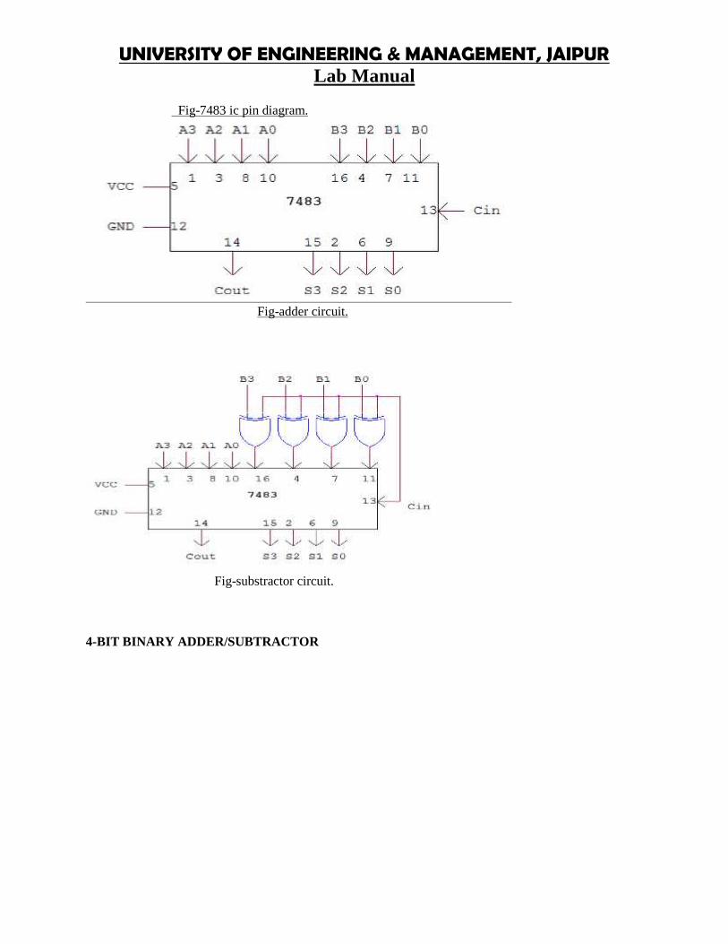
UNIVERSITY OF ENGINEERING & MANAGEMENT, JAIPURLab Manual
Fig-7483 ic pin diagram.
Fig-adder circuit.
Fig-substractor circuit.
4-BIT BINARY ADDER/SUBTRACTOR

UNIVERSITY OF ENGINEERING & MANAGEMENT, JAIPURLab Manual
Here A1, A2, A3, A4 and B1, B2, B3, B4 are the 8 Input. A1, A2, A3, A4 data set directlyconnected to the IC 7483 and B1, B2, B3, B4 fast connected to the XOR gates then the out putof XOR gates connected to 7483. Now XOR gates other I/P line are connected to the pin no 13of IC 7483, If the value of pin no 13 is ‘0’ means ADDITION and ‘1’ means SUBTRACTIONS1, S2, S3, S4 are the 4 out put where the sum/ borrow value is stored. So put any two 4 digitbinary number and get the sum of them.
PROCEDURE:1.for adder-• Check all the components for their working.• Insert the appropriate IC into the IC base.• Make connections as shown in the circuit diagram.• Apply augend and addend bits on A and B and cin=0.• Verify the results and observe the outputs.2.for substractor-• Check all the components for their working.• Insert the appropriate IC into the IC base.• Make connections as shown in the circuit diagram.• Apply Minuend and subtrahend bits on A and B and cin=1.• Verify the results and observe the outputs.
CONCLUSION:
Binary adder is one of the basic combinational logic circuits. The outputs of a combinational logic circuitdepend on the present input only. In other words, outputs of combinational logic circuit do not dependupon any previously applied inputs. It does not require any memory like component. Binary adder is oneof the basic combinational logic circuits as present state of input variables.
PRECAUTION:1. Digital IC trainer kit must be switched off while connecting the wires.2. IC Chips must be handled carefully so that pins could not be damaged.

UNIVERSITY OF ENGINEERING & MANAGEMENT, JAIPURLab Manual
EXPERIMENT NO-09
AIM:Design and implementation of 4 BCD adder using 7483 ic.
APPRATUS REQUIRED: IC 7483, IC 7432, IC 7408, IC 7400, etc.
THEORY: 4 BIT BCD ADDER:
Consider the arithmetic addition of two decimal digits in BCD, together with an input carry from a
previous stage. Since each input digit does not exceed 9, the output sum cannot be greater than 19, the 1
in the sum being an input carry. The output of two decimal digits must be represented in BCD and should
appear in the form listed in the columns. A BCD adder that adds 2 BCD digits and produce a sum digit in
BCD. The 2 decimal digits, together with the input carry, are first added in the top 4 bit adder to produce
the binary sum.
CIRCUIT DIAGRAM:
PIN DIAGRAM FOR IC 7483:

UNIVERSITY OF ENGINEERING & MANAGEMENT, JAIPURLab Manual
LOGIC DIAGRAM:
BCD ADDER:
TRUTH TABLE:
BCD SUM CARRYS4 S3 S2 S1 C0 0 0 0 00 0 0 1 00 0 1 0 00 0 1 1 00 1 0 0 00 1 0 1 00 1 1 0 00 1 1 1 01 0 0 0 01 0 0 1 01 0 1 0 11 0 1 1 11 1 0 0 11 1 0 1 11 1 1 0 11 1 1 1 1
PROCEDURE:• Check all the components for their working.• Insert the appropriate IC into the IC base.• Make connections as shown in the circuit diagram.• Verify the Truth Table and observe the outputs.
PRECAUTIONS:1. Digital IC trainer kit must be switched off while connecting the wires.2. IC Chips must be handled carefully so that pins could not be damaged.

UNIVERSITY OF ENGINEERING & MANAGEMENT, JAIPURLab Manual
EXPERIMENT NO:10
AIM: Design and implementation of 8:1 MULTIPLEXER .
APPRATUS REQUIRED: IC 74151
THEORY: Multiplexers are very useful components in digital systems. They transfer a large number ofinformation units over a smaller number of channels, (usually one channel) under the control of selectionsignals. Multiplexer means many to one. A multiplexer is a circuit with many inputs but only one output.By using control signals (select lines) we can select any input to the output. Multiplexer is also called asdata selector because the output bit depends on the input data bit that is selected. The general multiplexercircuit has 2n input signals, n control/select signals and 1 output signal.
CIRCUIT DIAGRAM:
TRUTH TABLE:

UNIVERSITY OF ENGINEERING & MANAGEMENT, JAIPURLab Manual
PROCEDURE:• Check all the components for their working.• Insert the appropriate IC into the IC base.• Make connections as shown in the circuit diagram.• Verify the Truth Table and observe the outputs.
CONCLUSION:
The truth table for an 8-to1 multiplexer is given below with eight combinations of inputs so as to generateeach output corresponds to input.For example, if S2= 0, S1=1 and S0=0 then the data output Y is equal to D2. Similarly the data outputsD0 to D7 will be selected through the combinations of S2, S1
PRECAUTIONS:1. Digital IC trainer kit must be switched off while connecting the wires.2. IC Chips must be handled carefully so that pins could not be damaged.
EXPERIMENT NO:11

UNIVERSITY OF ENGINEERING & MANAGEMENT, JAIPURLab Manual
AIM: Design and implementation of 8:1 MULTIPLEXER .
APPRATUS REQUIRED: IC 74153, IC 7432
THEORY: Multiplexers are very useful components in digital systems. They transfer a large number ofinformation units over a smaller number of channels, (usually one channel) under the control of selectionsignals. Multiplexer means many to one. A multiplexer is a circuit with many inputs but only one output.By using control signals (select lines) we can select any input to the output. Multiplexer is also called asdata selector because the output bit depends on the input data bit that is selected. The general multiplexercircuit has 2n input signals, n control/select signals and 1 output signal.
CIRCUIT DIAGRAM:

UNIVERSITY OF ENGINEERING & MANAGEMENT, JAIPURLab Manual
TRUTH TABLE:
PROCEDURE:• Check all the components for their working.• Insert the appropriate IC into the IC base.• Make connections as shown in the circuit diagram.• Verify the Truth Table and observe the outputs.
CONCLUSION:
The truth table for an 8-to1 multiplexer is given below with eight combinations of inputs so as to generateeach output corresponds to input.
PRECAUTIONS:1. Digital IC trainer kit must be switched off while connecting the wires.2. IC Chips must be handled carefully so that pins could not be damaged.

UNIVERSITY OF ENGINEERING & MANAGEMENT, JAIPURLab Manual
EXPERIMENT NO:12
AIM:Design and implementation of DEMULTIPLEXER .
APPRATUS REQUIRED:
THEORY : De-multiplexers perform the opposite function of multiplexers. They transfer a small numberof information units (usually one unit) over a larger number of channels under the control of selectionsignals. The general de-multiplexer circuit has 1 input signal, n control/select signals and 2n outputsignals. De-multiplexer circuit can also be realized using a decoder circuit with enable.
CIRCUIT DIAGRAM:
DE-MUX USING NAND GATES:
TRUTH TABLE:Enableinput
Datainput
Selectinputs
Outputs
E D S1 S0 Y3 Y2 Y1 Y0
1 0 X X X X X X0 1 0 0 0 0 0 10 1 0 1 0 0 1 0
0 1 1 0 0 1 0 00 1 1 1 1 0 0 0
IC 74139 (DEMUX) AND TRUTH TABLE:

UNIVERSITY OF ENGINEERING & MANAGEMENT, JAIPURLab Manual
Inputs OutputsEa S1 S0 Y3 Y2 Y1 Y0
1 X X 1 1 1 10 0 0 1 1 1 00 0 1 1 1 0 10 1 0 1 0 1 10 1 1 0 1 1 1
PROCEDURE:1. Check the components for their working.2. Insert the appropriate IC into the IC base.3. Make connections as shown in the circuit diagram.4. Provide the input data via the input switches and observe the output on output LEDs.
CONCLUSION:
A demultiplexer (or demux) is a device taking a single input signal and selecting one of manydata-output-lines, which is connected to the single input. A multiplexer is often used with acomplementary demultiplexer on the receiving end.
PRECAUTIONS:1. Digital IC trainer kit must be switched off while connecting the wires.2. IC Chips must be handled carefully so that pins could not be damaged.

UNIVERSITY OF ENGINEERING & MANAGEMENT, JAIPURLab Manual
EXPERIMENT NO-13
AIM: Design and implementation of BCD TO SEVEN SEGMENT DECODER.
APPRATUS REQUIRED: IC7447, 7-Segment display (common anode), Patch chords, resistor (1K_) &IC Trainer Kit .
THEORY: The Light Emitting Diode (LED) finds its place in many applications in these modernelectronic fields. One of them is the Seven Segment Display. Seven-segment displays contains thearrangement of the LEDs in “Eight” (8) passion, and a Dot (.) with a common electrode, lead (Anode orCathode). The purpose of arranging it in that passion is that we can make any number out of that byswitching ON and OFF the particular LED's. Here is the block diagram of the Seven Segment LEDarrangement. The Light Emitting Diode (LED), finds its place in many applications in this modernelectronic fields. One of them is the Seven Segment Display. Seven-segment displays contains thearrangement of the LEDs in “Eight” (8) passion, and a Dot (.) with a common electrode, lead (Anode orCathode). The purpose of arranging it in that passion is that we can make any number out of that byswitching ON and OFF the particular LED's. Here is the block diagram of the Seven Segment LEDarrangement.
LED’s are basically of two types-Common Cathode (CC) -All the 8 anode legs uses only one cathode, which is common. Common Anode(CA)-The common leg for all the cathode is of Anode type. A decoder is a combinational circuit thatconnects the binary information from ‘n’ input lines to a maximum of 2n unique output lines. The IC7447is a BCD to 7-segment pattern converter. The IC7447 takes the Binary Coded Decimal (BCD) as the inputand outputs the relevant 7 segment code.
CIRCUIT DIAGRAM:

UNIVERSITY OF ENGINEERING & MANAGEMENT, JAIPURLab Manual
TUTH TABLE:
PROCEDURE:• Check all the components for their working.• Insert the appropriate IC into the IC base.• Make connections as shown in the circuit diagram.• Verify the Truth Table and observe the outputs.
CONCLUSION:
A decoder is a combinational circuit which is used to convert a binary or BCD (Binary CodedDecimal) number to the corresponding decimal number . It can be a simple binary to decimaldecoder or a BCD to 7 segment decoder. Another relevant section is the combinational logiccircuitry
PRECAUTIONS:1. Digital IC trainer kit must be switched off while connecting the wires.2. IC Chips must be handled carefully so that pins could not be damaged.

UNIVERSITY OF ENGINEERING & MANAGEMENT, JAIPURLab Manual
EXPERIMENT NO:14
AIM: Design and implementation of BCD TO EXCESS 3CODE CONVERTOR..
APPRATUS REQUIRED: IC 7486, IC 7432, IC 7408, IC 7400, etc.
THEORY: Code converter is a combinational circuit that translates the input code word into a newcorresponding word. The excess-3 code digit is obtained by adding three to the correspondingBCD digit. To Construct a BCD-to-excess-3-code converter with a 4-bit adder feed BCDcodeto the 4-bit adder as the first operand and then feed constant 3 as the second operand.The output is the corresponding excess-3 code.To make it work as a excess-3 to BCD converter, we feed excess-3 code as the first operandand then feed 2's complement of 3 as the second operand. The output is the BCD code.
CIRCUIT DIAGRAM:
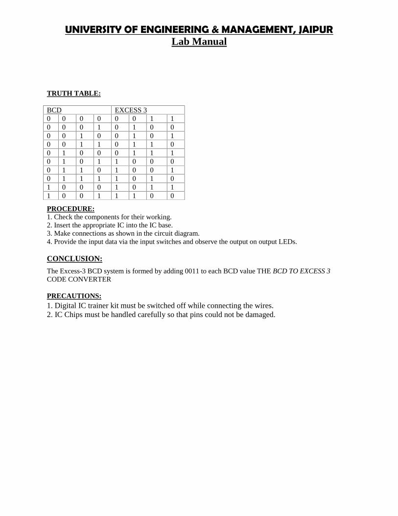
UNIVERSITY OF ENGINEERING & MANAGEMENT, JAIPURLab Manual
TRUTH TABLE:
PROCEDURE:1. Check the components for their working.2. Insert the appropriate IC into the IC base.3. Make connections as shown in the circuit diagram.4. Provide the input data via the input switches and observe the output on output LEDs.
CONCLUSION:
The Excess-3 BCD system is formed by adding 0011 to each BCD value THE BCD TO EXCESS 3CODE CONVERTER
PRECAUTIONS:1. Digital IC trainer kit must be switched off while connecting the wires.2. IC Chips must be handled carefully so that pins could not be damaged.
BCD EXCESS 30 0 0 0 0 0 1 10 0 0 1 0 1 0 00 0 1 0 0 1 0 10 0 1 1 0 1 1 00 1 0 0 0 1 1 10 1 0 1 1 0 0 00 1 1 0 1 0 0 10 1 1 1 1 0 1 01 0 0 0 1 0 1 11 0 0 1 1 1 0 0

UNIVERSITY OF ENGINEERING & MANAGEMENT, JAIPURLab Manual
EXPERIMENT NO:15
AIM:To design and implement SR latch, SR flip flop and JK flip flop.
APPRATUS REQUIRED: IC 7486, IC 7432, IC 7408, IC 7400, etc.
THEORY: Logic circuits that incorporate memory cells are called sequential logic circuits; their outputdepends not only upon the present value of the input but also upon the previous values. Sequential logiccircuits often require a timing generator (a clock) for their operation. The latch (flip-flop) is a basic bi-stable memory element widely used in sequential logic circuits. Usually there are two outputs, Q and itscomplementary value. Some of the most widely used latches are listed below.SR LATCH:An S-R latch consists of two cross-coupled NOR gates. An S-R flip-flop can also be design using cross-coupled NAND gates as shown. The truth tables of the circuits are shown below. A clocked S-R flip-flophas an additional clock input so that the S and R inputs are active only when the clock is high. When theclock goes low, the state of flip-flop is latched and cannot change until the clock goes high again.Therefore, the clocked S-R flip-flop is also called “enabled” S-R flip-flop.
CIRCUIT DIAGRAM:
R-S LATCH:
TRUTH TABLE:S R Q Q’0 0 NC NC

UNIVERSITY OF ENGINEERING & MANAGEMENT, JAIPURLab Manual
0 1 0 11 0 1 01 1 FB FB
TRUTH TABLE:
S R Q Q’0 0 FB FB0 1 1 01 0 0 11 1 NC NC
S-R FLIP FLOP:
TRUTH TABLE:
CLK S R Q Q’0 0 00 0 10 1 00 1 11 0 01 0 11 1 01 1 1
J-K FLIP FLOP :CIRCUIT DIAGRAM AND TRUTH TABLE:
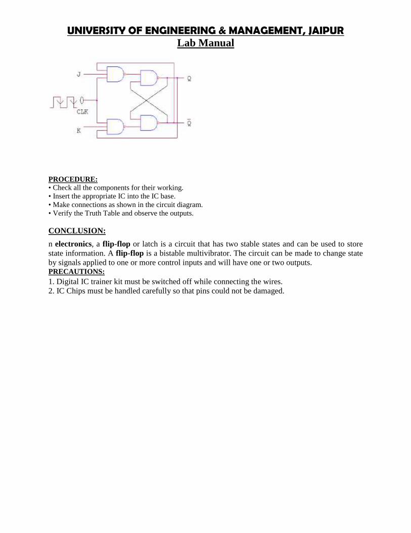
UNIVERSITY OF ENGINEERING & MANAGEMENT, JAIPURLab Manual
PROCEDURE:• Check all the components for their working.• Insert the appropriate IC into the IC base.• Make connections as shown in the circuit diagram.• Verify the Truth Table and observe the outputs.
CONCLUSION:
n electronics, a flip-flop or latch is a circuit that has two stable states and can be used to storestate information. A flip-flop is a bistable multivibrator. The circuit can be made to change stateby signals applied to one or more control inputs and will have one or two outputs.PRECAUTIONS:1. Digital IC trainer kit must be switched off while connecting the wires.2. IC Chips must be handled carefully so that pins could not be damaged.

UNIVERSITY OF ENGINEERING & MANAGEMENT, JAIPURLab Manual
EXPERIMENT NO:16
AIM:To design and implement ALU.
APPRATUS REQUIRED: IC 74181
THEORY: ALU (AIRTHMATIC LOGIC UNIT) is a circuit which performs arithmetic and logicaloperations. Arithmetic operations are like addition ,substraction, multiplication, and division. Logicaloperations are like and, or nand, nor ,not operations on bits. Here we will design the ALU for addition,substration and all logical operations. For this we need to design circuits for all the arithmetic and logicaloperations we want to perform. All these circuits then will be multiplexed through multiplexers. keepingin mind the complexity of circuit we will multiplexer only some number of circuits. for a particularoperation we have to select that particular circuit through multiplexer by selecting appropriate select linesof multiplexer.
CIRCUIT DIAGRAM:

UNIVERSITY OF ENGINEERING & MANAGEMENT, JAIPURLab Manual
PROCEDURE:• Check all the components for their working.• Insert the appropriate IC into the IC base.• Make connections as shown in the circuit diagram.• Verify the Truth Table and observe the outputs.
CONCLUSION:
The 74181 is a bit slice arithmetic logic unit (ALU), implemented as a 7400 series TTL integrated circuit.The first complete ALU on a single chip,[1] it was used as the arithmetic/logic core in the CPUs of manyhistorically significant minicomputers and other devices.
The 74181 represents an evolutionary step between the CPUs of the 1960s, which were constructed usingdiscrete logic gates, and today's single-chip CPUs or microprocessors.
PRECAUTIONS:1. Digital IC trainer kit must be switched off while connecting the wires.2. IC Chips must be handled carefully so that pins could not be damaged.

UNIVERSITY OF ENGINEERING & MANAGEMENT, JAIPURLab Manual

UNIVERSITY OF ENGINEERING & MANAGEMENT, JAIPURLab Manual
Title of Course: Microprocessors & Microcontrollers labCourse Code: EE594CL-T-P scheme: 0-0-3 Course Credit: 2
Objectives:The course is intended to create an appreciation for contemporary concepts in high performancemutli core super scalar architectures and appreciate their implementation in modern multiprocessors.
Learning Outcomes:Upon successful completion of the course, a student will have:1. An ability to define and explain the principles of computer architecture and the interfacingbetween its Hardware and software components2. An ability to write assembly programs and understand its machine code equivalent3. An in-depth understanding of architectural blocks involved in computer arithmetic, both integerand Floating point.4. An in-depth understanding of the data path inside a processor, its control and handling ofexceptions5. An in depth understanding of pipelining for 32-bit architectures6. An ability to understand and analyze computer memory hierarchy, at all levels of its organization,and the interaction between caches and main memory7. An ability to understand multi-processor architectures
Course Contents:Exercises that must be done in this course are listed below:Exercise No.1: Introduction to 8085 Microprocessor.Exercise No.2: a) Addition of 2 - 8 bit numbers
b) Subtraction of 2 - 8 bit numbersExercise No.3: a) Addition of 2 - 16 bit numbers
b) Subtraction of 2 – 16 bit numbersExercise No.4: a) Multiplication of 2 - 8 numbers
b) Division of 2 - 8 bit numbersExercise No.5: a) Ascending order
b) Descending orderExercise No.6: Factorial of Given NumbersExercise No.7: To write an assembly language program to displace Fibanocci Series.
Text Book:
Recommended Systems/Software Requirements:
1. 8085 kit.
.
Experiment 1:-

UNIVERSITY OF ENGINEERING AND MANAGEMENT, JAIPURLab Manual
AimTo study the microprocessor 8085
Architecture of 8085 Microprocessora) General purpose registerIt is an 8 bit register i.e. B,C,D,E,H,L. The combination of 8 bit register is known as register pair,which can hold 16 bit data. The HL pair is used to act as memory pointer is accessible to program.b) AccumulatorIt is an 8 bit register which hold one of the data to be processed by ALU and stored the result of theoperation.c) Program counter (PC)It is a 16 bit pointer which maintain the address of a byte entered to line stack.d) Stack pointer (Sp)It is a 16 bit special purpose register which is used to hold line memory address for line nextinstruction to be executed.e) Arithmetic and logical unitIt carries out arithmetic and logical operation by 8 bit address it uses the accumulator content asinput the ALU result is stored back into accumulator.f) Temporary registerIt is an 8 bit register associated with ALU hold data, entering an operation, used by themicroprocessor and not accessible to programs.g) FlagsFlag register is a group of fire, individual flip flops line content of line flag register will change afterexecution of arithmetic and logic operation. The line states flags arei) Carry flag (C)ii) Parity flag (P)iii) Zero flag (Z)iv) Auxiliary carry flag (AC)v) Sign flag (S)
h) Timing and control unitSynchronous all microprocessor, operation with the clock and generator and control signal from itnecessary to communicate between controller and peripherals.i) Instruction register and decoderInstruction is fetched from line memory and stored in line instruction register decoder the storedinformation.j) Register Array
These are used to store 8 bit data during execution of some instruction.
PIN DescriptionAddress Bus1. The pins Ao – A15 denote the address bus.2. They are used for most significant bit
Address / Data Bus1. AD0 – AD7 constitutes the address / Data bus2. These pins are used for least significant bit
ALE : (Address Latch Enable)1. The signal goes high during the first clock cycle and enables the lower order address bits.
IO / M1. This distinguishes whether the address is for memory or input.2. When this pins go high, the address is for an I/O device.
S0 – S1

UNIVERSITY OF ENGINEERING & MANAGEMENT, JAIPURLab Manual
S0 and S1 are status signal which provides different status and functions.RD1. This is an active low signal2. This signal is used to control READ operation of the microprocessor.
WR1. WR is also an active low signal2. Controls the write operation of the microprocessor.
HOLD1. This indicates if any other device is requesting the use of address and data bus.
HLDA1. HLDA is the acknowledgement signal for HOLD2. It indicates whether the hold signal is received or not.
INTR1. INTE is an interrupt request signal2. IT can be enabled or disabled by using software
INTA1. Whenever the microprocessor receives interrupt signal2. It has to be acknowledged.
RST 5.5, 6.5, 7.51. These are nothing but the restart interrupts2. They insert an internal restart junction automatically.
TRAP1. Trap is the only non-maskable interrupt2. It cannot be enabled (or) disabled using program.
RESET IN1. This pin resets the program counter to 0 to 1 and results interrupt enable and HLDA flip flops.
X1, X2These are the terminals which are connected to external oscillator to produce the necessary andsuitable clock operation.SIDThis pin provides serial input dataSODThis pin provides serial output dataVCC and VSS1. VCC is +5V supply pin2. VSS is ground pin
Specifications1. ProcessorsIntel 8085 at E144 MHz clock2. MemoryMonitor RAM: 0000 – IFFFEPROM Expansion: 2000 – 3FFF’s0000 – FFFSystem RAM: 4000 – 5FFFMonitor data area 4100 – 5FFFRAM Expansion 6000 – BFFF3. Input / OutputParallel: A8 TTL input timer with 2 number of 32-55 only input timer available in -85 EBI.

UNIVERSITY OF ENGINEERING AND MANAGEMENT, JAIPURLab Manual
Serial: Only one number RS 232-C, Compatible, crucial interface using 8281ATimer: 3 channel -16 bit programmable units, using 8253 channel ‘0’ used for no band late. Clockgenerator. Channel ‘1’ is used for single stopping used program.Display: 6 digit – 7 segment LED display with filter 4 digit for adder display and 2 digit for datadisplay.Key board: 21 keys, soft keyboard including common keys and hexa decimal keys.
RES: Reset keys allow to terminate any present activity and retain to - 85 its on initializestate.
INT: Maskable interrupt connect to CPU’s RST 7.5 interruptDEC: Decrement the adder by 1EXEC: Execute line particular value after selecting address through go command.NEXT: Increment the address by 1 and then display its content.Key Functions:i. Hex entry key ‘0’ii. Substituting memory content where “next” key is paused immediately after 1, take used to stcutting address.iii. Register key ‘E’
i) Hex code entry (1)ii) Register key ‘D’
i) Hex code entry ‘2’ii) Retricre data from data ‘memory’ to data topiii) Register key ‘C’
i) Hex code entry ‘3’ii) Retricre data from memory to topiii) Register key ‘B’
i) Hex key entry ‘C’ii) Block search from byteiii) Register key ‘F’
i) Hex key entry ‘5’ii) Fill block of RAM memory with desired dataiii) Register key ‘A’
i) Hex key entry ‘6’ii) TN/Tl used for sending (or) receivingiii) Register key ‘H’
i) Hex key entry ‘7’ii) Register key ‘H’
i) Register key ‘S’ii) Register key ‘I’
i) Hex key entry ‘A’ii) Function key F3iii) Register key “ph”
i) Hex key entry “y”ii) Signal step program (instruction by instruction)
i) Hex key entry “c”

UNIVERSITY OF ENGINEERING & MANAGEMENT, JAIPURLab Manual
ii) Much a block of memory from a linear blockiii) Register key “SH”
i) Hex key Dii) Compare 2 memory block
i) Hex key entry ‘B’ii) Check a block from flameiii) Register key “SPL”
i) Hex key ‘E’ii) Insert by test into memory (RAM)
i) Hex key ‘F’ii) Delete byte from memory RAM
System Power ConsumptionMicro BSEB2 MICRO SSEB+5V @ 1Amp +5V@ 800 mA+12V @ 200 mA
- 12V @ 100 mA
Power Supply SpecificationMICRO SSEM230V, AC @ 80 Hz
+5V @ 600 mA

UNIVERSITY OF ENGINEERING AND MANAGEMENT, JAIPURLab Manual
IC’s Used8085 - 8 bit p8253 - programmable internal timer8255 - programmable peripheral interface8279 - programmable key boards / display interface8251 - programmable communication interface2764 - 8 KV VV EPROM6264 - 8K STATIC PROM7414 - Hex inverter7432 - Quad 21/p OR GATE7409 - Quad 21/p AND GATE7400 - NAND Gate7404 - Dual D-FF74373 - Octal ‘D’ Latch74139 - Dual 2 to 4 line decoder74138 - 3 to 8 line decoder
In Enter Program into Trainer Kit1. Press ‘RESET’ key2. Sub (key processor represent address field)3. Enter the address (16 bit) and digit in hex4. Press ‘NEXT’ key5. Enter the data6. Again press “NEXT”7. Again after taking the program, are use HLT instruction its Hex code

UNIVERSITY OF ENGINEERING & MANAGEMENT, JAIPURLab Manual
8. Press “NEXT”
How to executive program1. Press “RESET”2. Press “GO”3. Enter the address location in which line program was executed4. Press “Execute” key
Result:Thus 8085 microprocessor was studied successfully.
Experiment 2(a) :-

UNIVERSITY OF ENGINEERING AND MANAGEMENT, JAIPURLab Manual
Aim:To write an assembly language for adding two 8 bit numbers by using micro processor kit.Apparatus required:8085 micro processor kit(0-5V) DC batteryAlgorithm:Step 1 : Start the microprocessorStep 2 : Intialize the carry as ‘Zero’Step 3 : Load the first 8 bit data into the accumulatorStep 4 : Copy the contents of accumulator into the register ‘B’Step 5 : Load the second 8 bit data into the accumulator.Step 6 : Add the 2 - 8 bit datas and check for carry.Step 7 : Jump on if no carryStep 8 : Increment carry if there isStep 9 : Store the added request in accumulatorStep 10 : More the carry value to accumulatorStep 11 : Store the carry value in accumulatorStep 12 : Stop the program execution.

UNIVERSITY OF ENGINEERING & MANAGEMENT, JAIPURLab Manual
Calculation 1111 11111111 1111---------------(1) 1111 1110=========F EResult:The assembly language program for 8 bit addition of two numbers was executed successfully byusing 8085 micro processing kit.
Experiment 2 (b): -

UNIVERSITY OF ENGINEERING AND MANAGEMENT, JAIPURLab Manual
Aim:To write a assembly language program for subtracting 2 bit (8) numbers by using- 8085 microprocessor kit.Apparatus required:8085 micro processor kit(0-5V) DC batteryAlgorithm:Step 1 : Start the microprocessorStep 2 : Intialize the carry as ‘Zero’Step 3 : Load the first 8 bit data into the accumulatorStep 4 : Copy the contents of contents into the register ‘B’Step 5 : Load the second 8 bit data into the accumulator.Step 6 : Subtract the 2 8 bit datas and check for borrow.Step 7 : Jump on if no borrowStep 8 : Increment borrow if there isStep 9 : 2’s compliment of accumulator is found outStep 10 : Store the result in the accumulatorStep 11 : More the borrow value from ‘c’ to accumulatorStep 12 : Store the borrow value in the accumulatorStep 13 : Stop program execution

UNIVERSITY OF ENGINEERING & MANAGEMENT, JAIPURLab Manual
Calculation 05 – 0707 – 0111CMA 1000ADJ 0.1 0001------100105 - 0101------1110 (-2)
Result:The assembly language program subtraction of two 8 bit numbers was executed successfully byusing 8085 micro processing kit.
Experiment 3(a) :-

UNIVERSITY OF ENGINEERING AND MANAGEMENT, JAIPURLab Manual
Aim:To write an assembly language program for adding two 16 bit numbers using 8085 micro processorkit.Apparatus required:8085 micro processor kit(0-5V) DC batteryAlgorithm:Step 1 : Start the microprocessorStep 2 : Get the 1st 8 bit in ‘C’ register (LSB) and 2nd 8 bit in ‘H’ register (MSB) of 16 bit number.Step 3 : Save the 1st 16 bit in ‘DE’ register pairStep 4 : Similarly get the 2nd 16 bit number and store it in ‘HL’ register pair.Step 5 : Get the lower byte of 1st number into ‘L’ registerStep 6 : Add it with lower byte of 2nd numberStep 7 : tore the result in ‘L’ registerStep 8 : Get the higher byte of 1st number into accumulatorStep 9 : Add it with higher byte of 2nd number and carry of the lower bit addition.Step 10 : Store the result in ‘H’ registerStep 11 : Store 16 bit addition value in ‘HL’ register pairStep 12 : Stop program execution

UNIVERSITY OF ENGINEERING & MANAGEMENT, JAIPURLab Manual
Calculation 0000 0100 0000 00010000 0011 0000 0010---------------------------------0000 0111 0000 00110 7 0 3

UNIVERSITY OF ENGINEERING AND MANAGEMENT, JAIPURLab Manual
Result:The assembly language program for addition of two 16 bit numbers was executed using 8085 microprocessing kit.
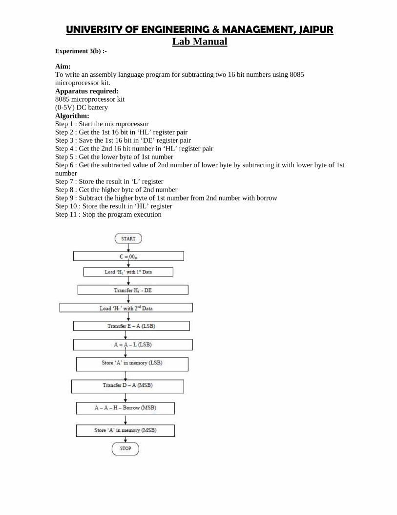
UNIVERSITY OF ENGINEERING & MANAGEMENT, JAIPURLab Manual
Experiment 3(b) :-
Aim:To write an assembly language program for subtracting two 16 bit numbers using 8085microprocessor kit.Apparatus required:8085 microprocessor kit(0-5V) DC batteryAlgorithm:Step 1 : Start the microprocessorStep 2 : Get the 1st 16 bit in ‘HL’ register pairStep 3 : Save the 1st 16 bit in ‘DE’ register pairStep 4 : Get the 2nd 16 bit number in ‘HL’ register pairStep 5 : Get the lower byte of 1st numberStep 6 : Get the subtracted value of 2nd number of lower byte by subtracting it with lower byte of 1stnumberStep 7 : Store the result in ‘L’ registerStep 8 : Get the higher byte of 2nd numberStep 9 : Subtract the higher byte of 1st number from 2nd number with borrowStep 10 : Store the result in ‘HL’ registerStep 11 : Stop the program execution

UNIVERSITY OF ENGINEERING AND MANAGEMENT, JAIPURLab Manual
Result:The assembly language program for subtraction of two 16 bit numbers was executed by using 8085micro processing kit.

UNIVERSITY OF ENGINEERING & MANAGEMENT, JAIPURLab Manual
Experiment 4(a) :-
Aim:To write an assembly language for multiplying two 8 bit numbers by using 8085 micro processor kit.Apparatus required:8085 microprocessor kit(0-5V) DC batteryAlgorithm:Step 1 : Start the microprocessorStep 2 : Get the 1st 8 bit numbersStep 3 : Move the 1st 8it number to register ‘B’Step 4 : Get the 2nd 8 bit numberStep 5 : Move the 2nd 8 bit number to register ‘C’Step 6 : Intialise the accumulator as zeroStep 7 : Intialise the carry as zeroStep 8 : Add both register ‘B’ value as accumulatorStep 9 : Jump on if no carryStep 10 : Increment carry by 1 if there isStep 11 : Decrement the 2nd value and repeat from step 8, till the 2nd value becomes zero.Step 12 : Store the multiplied value in accumulatorStep 13 : Move the carry value to accumulatorStep 14 : Store the carry value in accumulator

UNIVERSITY OF ENGINEERING AND MANAGEMENT, JAIPURLab Manual

UNIVERSITY OF ENGINEERING & MANAGEMENT, JAIPURLab Manual
Experiment 4(b) :-
Aim:To write an assembly language program for dividing two 8 bit numbers using microprocessor kit.Apparatus required:8085 microprocessor kit(0-5V) DC batteryAlgorithm:Step 1 : Start the microprocessorStep 2 : Intialise the Quotient as zeroStep 3 : Load the 1st 8 bit dataStep 4 : Copy the contents of accumulator into register ‘B’Step 5 : Load the 2nd 8 bit dataStep 6 : Compare both the valuesStep 7 : Jump if divisor is greater than dividendStep 8 : Subtract the dividend value by divisor valueStep 9 : Increment QuotientStep 10 : Jump to step 7, till the dividend becomes zeroStep 11 : Store the result (Quotient) value in accumulatorStep 12 : Move the remainder value to accumulatorStep 13 : Store the result in accumulatorStep 14 : Stop the program execution

UNIVERSITY OF ENGINEERING AND MANAGEMENT, JAIPURLab Manual
Result:The assembly language program for division of two 8 bit numbers was executed using 8085 microprocessing kit.
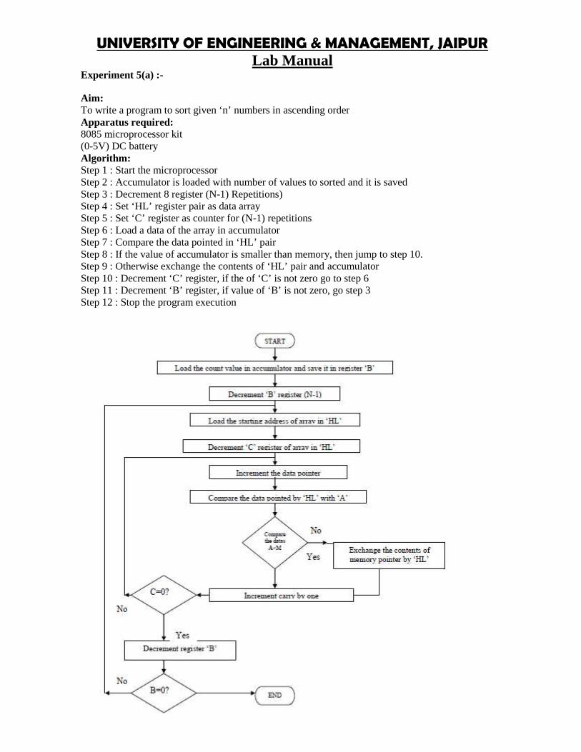
UNIVERSITY OF ENGINEERING & MANAGEMENT, JAIPURLab Manual
Experiment 5(a) :-
Aim:To write a program to sort given ‘n’ numbers in ascending orderApparatus required:8085 microprocessor kit(0-5V) DC batteryAlgorithm:Step 1 : Start the microprocessorStep 2 : Accumulator is loaded with number of values to sorted and it is savedStep 3 : Decrement 8 register (N-1) Repetitions)Step 4 : Set ‘HL’ register pair as data arrayStep 5 : Set ‘C’ register as counter for (N-1) repetitionsStep 6 : Load a data of the array in accumulatorStep 7 : Compare the data pointed in ‘HL’ pairStep 8 : If the value of accumulator is smaller than memory, then jump to step 10.Step 9 : Otherwise exchange the contents of ‘HL’ pair and accumulatorStep 10 : Decrement ‘C’ register, if the of ‘C’ is not zero go to step 6Step 11 : Decrement ‘B’ register, if value of ‘B’ is not zero, go step 3Step 12 : Stop the program execution

UNIVERSITY OF ENGINEERING AND MANAGEMENT, JAIPURLab Manual

UNIVERSITY OF ENGINEERING & MANAGEMENT, JAIPURLab Manual
Experiment 5(b):-
Aim:To write a program to sort given ‘n’ numbers in descending orderApparatus required:8085 microprocessor kit(0-5V) DC batteryAlgorithm:Step 1 : Start the microprocessorStep 2 : Load the number of values into accumulator and save the number of values in register ‘B’Step 3 : Decrement register ‘B’ for (N-1) RepetitionsStep 4 : Set ‘HL’ register pair as data array address pointer and load the data of array in accumulatorStep 5 : Set ‘C’ register as counter for (N-1) repetitionsStep 6 : Increment ‘HL’ pair (data address pointer)Step 7 : Compare the data pointed by ‘HL’ with accumulatorStep 8 : If the value of accumulator is larger than memory, then jump to step 10, otherwise next step.Step 9 : Exchange the contents of memory pointed by ‘HL’ and accumulatorStep 10 : Decrement ‘C’ register, if the of ‘C’ is not zero go to step 6, otherwise next step.Step 11 : Decrement ‘B’ register, if ‘B’ is not zero, go step 3, otherwise next step.Step 12 : Stop the program execution

UNIVERSITY OF ENGINEERING AND MANAGEMENT, JAIPURLab Manual

UNIVERSITY OF ENGINEERING & MANAGEMENT, JAIPURLab Manual
Experiment 6:-
Aim:To write an program to calculate the factorial of a number (between 0 to 8)Apparatus required:8085 microprocessor kit(0-5V) power supplyAlgorithm:Step 1 : Intialize the stack pointerStep 2 : Get the number in accumulatorStep 3 : Check for if the number is greater than 1. If no store the result otherwise go to next step.Step 4 : Load the counter and initialize resultStep 5 : Now factorial program in sub-routine is called.Step 6 : In factorial, initialize HL RP with 0. Move the count value to B Add HL content with Rp.Decrement count (for multiplication)Step 7 : Exchange content of Rp (DE) with HL.Step 8 : Decrement counter (for factorial) till zero flag is set.Step 9 : Store the resultStep 10 : Hault
Memory address Content4250 054251 (12010)

UNIVERSITY OF ENGINEERING AND MANAGEMENT, JAIPURLab Manual

UNIVERSITY OF ENGINEERING & MANAGEMENT, JAIPURLab Manual
Experiment 7:-

UNIVERSITY OF ENGINEERING AND MANAGEMENT, JAIPURLab Manual
Aim:To write an assembly language program to displace Fibanocci Series.
Apparatus required:8085 microprocessor kit(0-5V) DC battery
Algorithm:Step 1 : Start the microprocessorStep 2 : Load the length of series in the accumulator and decrement it by 2Step 3 : Move the value to register ‘D’Step 4 : Load the starting value of data value addressStep 5 : Intialise the 1st number as 00Step 6 : Move the pointer to 2nd data and intialise them as ‘01’Step 7 : Move the pointer to next position for next dataStep 8 : Intialise B as ‘00’ and C as ‘01’ for calculationsStep 9 : Copy the contents of ‘B’ to accumulatorStep 10 : Add the content of ‘C’ register to accumulatorStep 11 : Move the content ‘C’ to ‘B’ and ‘A’ to CStep 12 : Now store the result to memory pointed by ‘HL’ pairStep 13 : Move the pointer to next pointerStep 14 : Decrement 0 by 1 for counterStep 15 : If ‘D’ is not zero, go to step 9Step 16 : if ‘D’ is zero, end the program

UNIVERSITY OF ENGINEERING & MANAGEMENT, JAIPURLab Manual

UNIVERSITY OF ENGINEERING AND MANAGEMENT, JAIPURLab Manual
00 + 01 = 0101+ 01 = 0202 + 01 = 03Result:The assembly language for Fibonaci series was executed successfully using 8085 microprocessor kit.

UNIVERSITY OF ENGINEERING & MANAGEMENT, JAIPURCourse Description
Title of Course: Group DiscussionCourse Code: HU581L-T –P Scheme: 0-0-3 Course Credits: 2
A group discussion aims at a structured but informal exchange of knowledge, ideas, andperceptions among the participants on any issue, topic or sub-topic. Contributions are pooledtogether and examined in terms of their relevance and validity to the discussion objectives. Ifplanned and organized in a structured way and certain essential conditions are met, it can providea highly enriching and stimulating experience to the participants. Lets us see, the objectives,different steps involved in it and its limitations.
Objectives of a Group Discussion
Produce a range of options or solutions, addressing a particular problem or an issue.
Generate a pile of ideas by examining issues in greater depth, looking at differentdimensions of these issues.
Broaden the outlook of the participants through cross-fertilization and exposure to new anddifferent experiences and ideas and enrich their understanding of the issues underdiscussion.
Develop their skills in interpersonal communication and in expressing their views in a clearand succinct manner.
Effective means of changing attitudes through the influence of peers in the group
Valuable means of obtaining feedback for the training team on verbal skills, motivationlevel and personal traits of the participants and characteristics of the group
Steps in organizing a Group Discussion
Setting up the Groups
Planning a Group Discussion
Preparation of Group Reports
Presentation and Consolidation of Group Reports
Limitations
If the group is large, not all the members may get the opportunity to participate andcontribute to the discussion.
If the task is not clearly defined, the discussion may lack focus and, as a result, it may beunproductive.
Difficulties can arise if the leader is unskilled in guiding the discussion and/or not familiarwith the topic or the issues.
Some members may dominate and, in a way, hijack the discussion.

UNIVERSITY OF ENGINEERING & MANAGEMENT, JAIPURCourse Description
As this is a group task, some members may take it easy and not feel constrained toparticipate.
Learning outcomes
After studying this course, you should be able to:
understand the key skills and behaviours required to facilitate a group discussion
prepare effectively before facilitating a meeting
consider some of the difficult behaviours that can occur in meetings
think of some possible strategies for dealing with these.