university of huddersfield repositoryeprints.hud.ac.uk/8599/1/opoznumerical.pdf · university of...
TRANSCRIPT

University of Huddersfield Repository
Opoz, Tahsin Tecelli and Chen, Xun
Numerical Simulation of Single Grit Grinding
Original Citation
Opoz, Tahsin Tecelli and Chen, Xun (2010) Numerical Simulation of Single Grit Grinding. In: Proceeding of the 16th International Conference on Automation & Computing, 11 Sept 2010, Birmingham, UK.
This version is available at http://eprints.hud.ac.uk/id/eprint/8599/
The University Repository is a digital collection of the research output of theUniversity, available on Open Access. Copyright and Moral Rights for the itemson this site are retained by the individual author and/or other copyright owners.Users may access full items free of charge; copies of full text items generallycan be reproduced, displayed or performed and given to third parties in anyformat or medium for personal research or study, educational or notforprofitpurposes without prior permission or charge, provided:
• The authors, title and full bibliographic details is credited in any copy;• A hyperlink and/or URL is included for the original metadata page; and• The content is not changed in any way.
For more information, including our policy and submission procedure, pleasecontact the Repository Team at: [email protected].
http://eprints.hud.ac.uk/

Numerical Simulation of Single Grit Grinding
Tahsin Tecelli Öpöz, Xun Chen Centre for Precision Technologies, School of Computing and Engineering
University of Huddersfield, HD1 3DH Huddersfield, UK
Abstract— The purpose of this research is to investigate
grinding performance by using numerical simulation. The
interaction between single grit and workpiece is taken into
account to reveal the grinding mechanism realistically.
Simplified finite element model of grit-workpiece interaction
was simulated by using ABAQUS/Standard. Iterative
adaptive remeshing technique was performed to create fine
meshes around contact area. Spherical grit was engaged to
workpiece with indentation and scratching simultaneously.
Grits were modeled by using Al2O3 and CBN material
properties. Comparison has been done in a defined scratch
path with maximum 2 µm undeformed chip thickness.
Material ploughing phenomenon, force variation and the
influence of mesh size are discussed.
Keywords - finite element modelling; single grit; grinding
I. INTRODUCTION
Ever increased demands of high surface quality and integrity make finishing technology especially ultra precision grinding more crucial. Finishing processes, particularly grinding, are expensive and time consuming, and their quality strongly depends on operator’s skill and experience. Grinding is a material removal process by arbitrarily bounded abrasive grits on the wheel periphery. The grits do not have certainly defined geometric shape for their cutting edges. Therefore, grinding is not a well-defined process compared to other machining processes. Many researchers [1] have dedicated to get optimum conditions that provide highly desired surface quality and integrity within reasonable cost and time. In order to obtain good quality of the ground part with high efficiency and low cost, understanding of grinding mechanism and prediction of grinding performance become crucial.
Experimental investigation is good for the validation of grinding behaviours under the confined conditions. However, performing experiment for each different case is cumbersome, time consuming and extremely costly. In order to overcome these difficulties, the prediction of grinding performance could be done by analyzing grinding process using finite element model simulation.
Successful modelling and simulation rely on detailed knowledge of the process and computing technology advance. Thus, quality of any simulation depends exclusively on the quality of the model used. Models can be divided into two groups; one is physical model which is established based on conformity to physical laws, using a mathematical formulation of the quantitative model. The other is empirical model established by means of measured values which have been obtained from grinding tests [1]. The physical models of grinding process including grinding force models, chip thickness models, topography models, grinding energy models, and
temperature models have been continuously investigated by researchers [2-8]. For the simulation of these physical models, finite element technique is mostly reliable tool to demonstrate the process behaviours.
Often, grinding has been modelled as a heat transfer process where a grinding wheel has been modelled as moving heat source, or elasto-mechanical process where the grinding wheel has been modelled as mechanical surface pressure [1,7,9,10]. This type of models is called as macro-scale model dealing with the interaction between grinding wheel and workpiece at large scale [9,11]. The other approach is modelling of single grit action during machining process, which is so called micro-scale model that considers individual grit interaction with workpiece [9,11]. Though there have been a great number of experimental works on single grit grinding to identify the grinding characteristics in micro scale, only a few finite element models consider grinding physical performance at such level [2,12-14].
Doman et al [11] reviewed finite element models in grinding both considering macro and micro-scale. Regarding the difficulty in chip formation with small depth of cut in grinding process, orthogonal cutting process model with highly negative rake angle are often used to represent simplified abrasive grit cutting processes. Ohbuchi and Obikawa [14] developed a thermo-elastic-plastic finite element model of orthogonal cutting with a large negative rake angle in order to understand the mechanism and thermal performance of grinding. They indicated that the differences in chip formation between cutting and grinding. According to their results, a higher rake angles would form chips unconditionally. It was discovered whilst grinding with abrasive grit has a lower range of rake angles, the grinding chip formation is restricted by the critical cutting speed and critical undeformed chip thickness. They found critical cutting speed and uncut chip thickness for efficient material removal depend on the rake angle, and suggested that the high speed grinding was preferable to the micro cutting with abrasives. The critical cutting speed increased with decreasing rake angle if the rake angle was less than -15°. Most researches revealed that the size effect, cutter edge radius and minimum undeformed chip thickness in micro machining (milling, turning etc.) has similar effects at micro grinding process [15]. Ohbuchi and Obikawa [5] further investigated the surface generation of grinding considering the grit shape and cutting speed. They supported finite element model with experimental work and concluded that there exist a relation between cutting speed and critical chip thickness while rake angle is -45°, the cutting speed is approximately inverse proportional to the critical undeformed chip thickness. Under critical value of undeformed chip thickness only side-flow occurs.

Takenaka [16] investigated the single grit action and observed chips formation even at a smaller depth of cut of 0.4 µm. The proportion of ploughing process increases with the decrease of depth of cut and in the case of extremely small depths of cut, the rubbing process would be prominent. Matsuo et al [17] investigated the effect of grit shape on the forces and pile-up. And he concluded that grinding force increases linearly with increasing cross sectional area, and the slope of lines is greater as apex angle becomes larger.
Klocke [12] reviewed the modelling and simulation techniques in grinding process. He also stated that the first complete simulations reproducing a single grit cutting were made at the laboratory for machine tools of the RWTH Aachen and at the IWT of the University of Bremen. Generally researchers [9,11,12] claim the simulation at microscopic level concerning the grinding process is more promising than that at macroscopic level, because the process behaviour can be more realistically reproduced with this method. Klocke et al [18] performed single abrasive grit scratching a cutting edge of 50 µm radius without coolant. They aimed to predict the type and the value of the wear on the single grit, removal mechanism of the workpiece material and the arising stresses on the workpiece. Most recently Doman et al [13] developed a three dimensional finite element model to investigate ploughing and rubbing in scratch tests by using LS-DYNA software. In their study, the grit was modelled as a 2 mm diameter alumina sphere. Despite the large grit size, they pointed out that the transition between rubbing and ploughing phases occurred at a depth slightly larger than 3 µm in their FE model although experimentally lower values of transition depth were observed. Park and Liang [2] proposed a single grit model both considering cutting and ploughing effects to predict the material deformation and microgrinding forces. The ploughing force was calculated from indentation force using 2D-Deform software. Chae et al [19] stated that the chip may not form when the depth of cut is less than a minimum chip thickness. The small depth of cut due to low feed rate and small edge radius of the tool cause a large negative rake angle. Such ploughing phenomenon causes a rough surface and elastic recovery of the workpiece. Zhang and Peng [20] developed a three dimensional finite element model to predict material deformation for silicon nitride subjected to single grit grinding
This paper intends to demonstrate the application of physical models by using finite element modelling technique. A FEM simulation of single grit-workpiece interaction will be presented considering the material properties of CBN and Al2O3 abrasive grits to explore the grinding material removal mechanisms and induced grinding forces. Finite element analysis of a single grit grinding is simulated by using Abaqus/Standard. In a defined grit moving path with different abrasive grit materials, maximum uncut chip thickness is 2 µm, contact interaction between grit and workpiece is presented with and without friction consideration. Force variation and rubbing and ploughing phase transformation will be investigated.
II. FINITE ELEMENT SIMULATION
A. Simulation Conditions
A 3D single grit FEM simulation is performed by using ABAQUS/Standard. The abrasive grits are modelled by using the material properties of CBN (Cubic Boron Nitride E=909 GPa, ν=0.121, and ρ=3400 kg.m-3) and Al2O3 (E=530GPa, ν=0.2, and ρ=4000 kg.m-3) with same geometrical shape of hemispherical solid of a diameter of 100 µm. Workpiece is modelled with dimensions of 2mm×1mm×0.5 mm. The workpiece material is steel, whose elastic material properties are E=200 GPa, ν=0.3, ρ=7800 kg.m-3 and yield stresses are 180, 200, 250, 300 MPa correspond to plastic strains 0, 0.1, 0.25, 0.3 respectively. The grit cutting path is defined as in Fig. 1 to simulate different grinding position statuses. The grit and workpiece are modelled by using C3D4 element, which is a four node linear tetrahedron element. During simulation, it is necessary to remesh the part when severe mesh distortion takes place. The remeshing technique is based on the refinement and coarsening techniques and avoids entirely remeshing the workpiece. Iterative adaptive remeshing technique is used to get finer element size in grit-workpiece engagement area. The remeshing is governed by mesh element size and equivalent plastic strain error indicator is used to make decision about satisfaction of element geometry and contact conformity at interaction area. Finer meshes over the cutting area provide better conformity of contact between grit and workpiece. Adaptive remeshing is typically used for accuracy control, although it can also be used for distortion control in some situations. The adaptive remeshing process involves the iterative generation of multiple dissimilar meshes to determine a single, optimized mesh that is used throughout an analysis. The goal of adaptive remeshing is to obtain a solution that satisfies mesh discretization error indicator targets [21]. Remeshed workpiece with both Al2O3 and CBN grit is shown in Fig. 2. It can be seen that finer meshes are found in CBN simulation. Number of elements on CBN and Al2O3 grit are 13859 and 784, respectively.
Figure 1. Schematic drawing of grain movement trajectory with a maximum depth of cut 2 µm.

Figure 2. Al2O3 (front one) and CBN (back one) grit simulation on remeshed workpiece.
B. Simulation Results with Al2O3 and CBN grit
Rubbing, ploughing and chip formation are the three phases taken place during a grinding process. The rubbing phase only includes elastic deformation while the ploughing phase includes both elastic and plastic deformations. During the simulation, the grit acts as a master part while workpiece is a slave. The grits have designed geometrically perfect sphere shape. However, the asperities over the grits caused by the coarse meshing may influence the simulation results. At the initial contact stage, grits with high asperity lead to primary indention into the workpiece. Though it is very low depth around 0.3 µm, its effect should be taken into account throughout the simulation.
The deformation stress distribution along the simulation path is illustrated with deformed contour lines in Fig. 3. It is very obvious to detect stress and deformation change during process. The deeper point indicated with 'PE' in Fig. 3 represents where the grain engaged with the workpiece during simulation and includes both elastic and plastic deformations, while the unengaged section exampled as 'P' only includes plastic deformation. Workpiece material in front of grain indicated with 'pile-up' would be attributed to the beginning stage of chip formation. When the stresses reach the breaking point, chips may form. Stresses due to elastic deformation would disappear from workpiece after the grain passed and only residual stresses due to plastic deformation remain in the workpiece.
Figure 3. Stress distribution during simulation (Al2O3grit)
The simulation shows that grit material has an influential effect on the deformation of workpiece as shown in Fig. 4. Whilst the harder abrasive grit like CBN causes higher deformation as ploughing material, the softer Al2O3 grit causes less ploughing material because the Al2O3 gives more deformation leading to a lower real depth of cut. Actually this can be expected, since alumina grit has higher compliance than CBN. The CBN is acting more rigid leading to higher stresses.
Variation in deformation means all other performance parameters like estimated force and also remeshing indicator target like equivalent plastic strains are all changed. Influence of friction coefficient is also affecting the deformed material quantity and forces. With frictional interaction, material deformation pile-up is increasing (Fig. 5). Equivalent plastic strain was used as indicator setting for remeshing strategy and three times iteration is applied to get finer mesh size around contact area. according to remeshing rules, mesh size is estimated and regenerated where the equivalent plastic strain is become higher to mitigate the distortion of element and increase the accuracy of material removal process. Finer meshes are also provide good contact conformity between grit and workpiece. Contact conformity is important to get reliable results from simulation. The equivalent plastic strain values are higher when CBN grit is used and lower when Al2O3 grit is used as shown in Fig. 6. This is evident in fig 6, where the workpiece engaged with CBN grit is remeshed with smaller size element than engaged with Al2O3 grit.
Although total forces exerted by the grit is obviously higher with CBN grit than with Al2O3 grit (Fig. 7). However, element mesh size may affect the force error slightly regarding initial indention into workpiece during first contact. The grit geometrical shape can be affected by mesh size, fine meshed grit has good approximate spherical shape while coarse meshed grit diverge from expected geometry. Such asperity of grit due to size of mesh element has effects on aforementioned contact conformity. Asperity effects on grinding performance can be investigated separately. Therefore, the elastic properties of grit materials are affecting the grinding performance indicated by forces, stresses, and deformation.
(a) Al2O3 grit
(b) CBN grit
Figure 4. Ploughing simulation
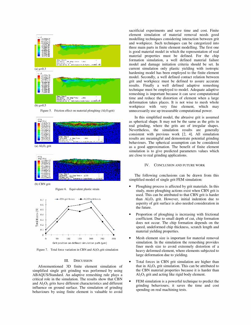
Figure 5. Friction effect on material ploughing (Al2O3grit)
(a) Al2O3 grit
(b) CBN grit
Figure 6. Equivalent plastic strain
Figure 7. Total force variation in CBN and Al2O3 grit simulation
III. DISCUSSION
Aforementioned 3D finite element simulation of simplified single grit grinding was performed by using ABAQUS/Standard. An adaptive remeshing rule plays a critical role in the simulation. The results show that CBN and Al2O3 grits have different characteristics and different influence on ground surface. The simulation of grinding behaviours by using finite element is valuable to avoid
sacrificial experiments and save time and cost. Finite element simulation of material removal needs good modelling techniques considering interaction between grit and workpiece. Such techniques can be categorized into three main parts in finite element modelling. The first one is good material model in which the representation of real material properties must be defined. For the chip formation simulation, a well defined material failure model and damage initiation criteria should be set. In current simulation only plastic yielding with isotropic hardening model has been employed to the finite element model. Secondly, a well defined contact relation between grit and workpiece must be defined to assure accurate results. Finally a well defined adaptive remeshing technique must be employed to model. Adequate adaptive remeshing is important because it can save computational time and reduce the distortion of element when a large deformation takes places. It is not wise to mesh whole workpiece with very fine element, which may unnecessarily use up treasurable computational power.
In this simplified model, the abrasive grit is assumed as spherical shape. It may not be the same as the grits in real grinding, where the grits are of irregular shapes. Nevertheless, the simulation results are generally consistent with previous work [2, 4]. All simulation results are meaningful and demonstrate potential grinding behaviours. The spherical assumption can be considered as a good approximation. The benefit of finite element simulation is to give predicted parameters values which are close to real grinding applications.
IV. CONCLUSION AND FUTURE WORK
The following conclusions can be drawn from this
simplified model of single grit FEM simulation:
• Ploughing process is affected by grit materials. In this study, more ploughing actions exist when CBN grit is used. This can be attributed to that CBN grit is harder than Al2O3 grit. However, initial indention due to asperity of grit surface is also needed consideration in the future.
• Proportion of ploughing is increasing with frictional coefficient. Due to small depth of cut, chip formation does not occur. The chip formation depends on the speed, undeformed chip thickness, scratch length and material yielding properties.
• Mesh element size is important for material removal simulation. In the simulation the remeshing provides finer mesh size to avoid extremely distortion of a heavy deformed element, where elements subjected to large deformation due to yielding.
• Total forces in CBN grit simulation are higher than that in Al2O3 grit simulation. This can be attributed to the CBN material properties because it is harder than Al2O3 grit and acting like rigid body element.
• FEM simulation is a powerful technique to predict the grinding behaviours; it saves the time and cost spending on real machining tests.
(a) µ=0.3
(b) µ=0.5

Future work of this research includes the chip formation with small depth of cut considering simplified single grit grinding model. For the chip formation process, failure model, damage initiation criteria, different remeshing technique, speed, depth of cut and orientation of grit (to take into account rake angle) will be taken into account. Three phases of grinding phenomenon will be discriminated clearly and simulation result will be supported with the experimental tests. After that, a precision grinding strategy will be developed to improve grinding performance especially for the free form surface grinding.
REFERENCES
[1] H.K. Tönshoff, J. Peters, I. Inasaki, T.Paul, “Modeling and Simulation of Grinding Processes,” Annals of the CIRP vol. 41-2, 1992, pp. 677-688.
[2] H.W. Park and S. Y. Liang, “Microgrinding force predictive modelling based on microscale single grain interaction analysis,” Int. J. Manufacturing Technology and Managament, vol. 12, 2007, pp. 25-28.
[3] S. Ghosh, A.B. Chattopadhyay, S, Paul, “Modelling of specific energy requirement during high-efficiency deep grinding,” Int J Mach Tool Manu, vol. 48, 2008, pp. 1242-1253.
[4] Y, Ohbuchi, T. Matsuo, “Force and chip formation in single-grit orthogonal cutting with shaped CBN and Diamond grains,” Annals of the CIRP, vol. 40, 1991, pp. 327-330.
[5] Y. Ohbuchi, T. Obikawa, “Surface generation model in grinding with effect of grain shape and cutting speed,” JSME Int J C-Mech Sy, vol. 49, 2006, pp. 114-120.
[6] S. Kannappan, S. Malkin, “Effect of grain size and operating parameters on the mechanics of grinding,” Journal of Engineering for Industry- TRANSACTION OF THE ASME, vol. 94, 1972, pp. 833-842.
[7] P.N. Moulik, H.T.Y. Yang , S. Chandrasekar, “Simulation of thermal stresses due to grinding,” Int J Mech Sci vol. 43, 2001, pp. 831-851.
[8] U.S. Patnaik Durgumahanti, Vijayender Singh, P. Venkateswara Rao, “A New model for grinding force prediction and analysis,” Int J Mach Tool Manu, vol. 50, 2010, pp. 231-240.
[9] E. Brinksmeier, J. C. Aurich, E. Govekar, C. Heinzel, H-W. Hoffmeister, F. Klocke, J. Peters, R. Rentsch, D.J. Stephenson, E. Uhlmann, K. Weinert, M. Wittmann,
“Advances in modeling and simulation of grinding processes,” Annals of the CIRP, vol. 55, 2006, pp. 667–696.
[10] A.G. J. Kundrák, D.E. Manolakos, K. Gyáni, A. Markopoulos, “Thermal modelling of surface grinding using implicit finite element techniques,” Int J Adv Manuf Tech, vol. 21, 2003, pp. 929-934.
[11] D.A. Doman, A. Warkentin, R. Bauer, “Finite element modeling approaches in grinding,” Int J Mach Tool Manu, vol. 49, 2009, pp. 109-116.
[12] F. Klocke, “Modelling and simulation of grinding processes,” 1st European conference on Grinding, Aachan 6-7 November, 2003.
[13] D.A. Doman, R. Bauer, A. Warkentin, “Experimentally validated finite element model of the rubbing and ploughing phases in scratch tests,” Proc. IMechE Part B: J. Engineering Manufacture, vol. 223, 2009, pp. 1519-1527.
[14] Y. Ohbuchi and T. Obikawa, “Finite element modeling of chip formation in the domain of negative rake angle cutting,” Journal of Engineering Materials Transaction of the ASME, vol. 125, 2003, pp. 324-332.
[15] X. Lai, H. Li, C. Li, Z. Lin, J. Ni., “Modelling and analysis of micro scale milling considering size effect micro cutter edge radius and minimum chip thickness,” Int J Mach Tool Manu, vol. 48, 2008, pp. 1-14.
[16] N. Takenaka, “A study on the grinding action by single grit,” Annals of the CIRP, vol. 13, 1966, pp. 183-190.
[17] T. Matsuo, S. Toyoura, E. Oshima, Y. Ohbuchi, “Effects of grain shape on cutting force in superabrasive single grit tests,” Annals of the CIRP, vol. 3, 1989, pp. 323-326.
[18] F. Klocke, T. Beck, S. Hoppe, T. Krieg, N. Müller, T. Nöthe, H-W. Raedt, K. Sweeney, “Examples of FEM application in manufacturing technology,” J Mater Process Tech, vol. 120, 2002, pp. 450-457.
[19] J. Chae, S.S. Park, T. Freiheit, “Investigation of micro-cutting operations,” Int J Mach Tool Manu, vol. 46, 2006, pp. 313-332.
[20] B. Zhang, X. Peng, “Grinding damage prediction for ceramic via CDM model,” Journal of Manufacturing Science and Engineering, vol. 122, 2000, pp. 51-58.
[21] ABAQUS/CAE Version 6.8 documentation.