university of nairobi faculty of...
TRANSCRIPT

UNIVERSITY OF NAIROBI
FACULTY OF ENGINEERING
DEPARTMENT OF MECHANICAL AND MANUFACTURING ENGINEERING
TITLE: JATROPHA OIL PRESSING MACHINE
PROJECT CODE: FML 01/12
BY
OMOTE MAKORI GEOFFREY F18/2699/2007
MWANGI DENNIS F18/1850/2007
SUPERVISOR: PROF. LUTI.F.MAKAU
Project report submitted in partial fulfillment of the
requirement for the award of the degree
of
Bachelor of Science in MECHANICAL ENGINEERING
of the University of Nairobi.
Submitted on: May, 2012

i
DECLARATION AND CERTIFICATION
This BSc. work is our original work and has not been presented for a degree award in this or any
other university.
…………………………. ……………………………..
OMOTE M GEOFFREY MWANGI DENNIS
F18/2699/2007 F18/1850/2007
This report has been submitted to the Department of Mechanical and Manufacturing Engineering
University of Nairobi with my approval as supervisor:
Prof. LUTI F. MAKAU
Sign
……………………………………………………………...
Date
………………………………………………………………

ii
ACKNOWLEDGEMENT
We express our sincere appreciation to Prof. Luti F. Makau for his guidance, advice, criticism,
systematic supervision, encouragements, and insight throughout this project.
We express our deep gratitude to Mrs. Lorna Omoudo C.E.O (Vanilla Jatropha foundation) for
her great help and effort during this project.
We also give special thanks go to our class colleagues for their valuable support and aid.
We also thank our beloved families for their great support and encouragement throughout this
project.

iii
TABLE OF CONTENTS
DECLARATION AND CERTIFICATION .................................................................................................... i
ACKNOWLEDGEMENT ........................................................................................................................ ii
LIST OF FIGURES ................................................................................................................................ vi
LIST OF TABLES ............................................................................................................................... viii
ABSTRACT ......................................................................................................................................... ix
CHAPTER 1: INTRODUCTION ...............................................................................................................1
1.1 ENERGY ............................................................................................................................................... 1
1.2 OBJECTIVES ......................................................................................................................................... 4
CHAPTER 2: LITERATURE REVIEW .......................................................................................................5
2.1BACKGROUND ...................................................................................................................................... 5
2.2 THE PLANT ........................................................................................................................................... 8
2.2.1 Sowing and germination ................................................................................................. 8
2.2.2 How it is planted ........................................................................................................... 10
2.2.3 Uses of the Jatropha curcas and its oil .......................................................................... 10
2.3 OIL EXTRACTION ................................................................................................................................ 10
2.3.1 Oil Extraction Efficiency .............................................................................................. 12
2.3.2 Oil as fuel...................................................................................................................... 12
2.4 ADVANTAGES OF USING JATROPHA OIL .......................................................................................... 12
CHAPTER 3: CASE STUDY .................................................................................................................. 13
3.1 INTRODUCTION ................................................................................................................................. 13
3.2 METHODOLOGY OF THE RESEARCH .................................................................................................. 14
3.3 ECONOMIC VIABILITY OF BIODIESEL ................................................................................................. 16
3.4 PRICE COMPETITIVENESS OF BIODIESEL ........................................................................................... 16
3.4.1 Price of Jatropha seeds and oil ..................................................................................... 16

iv
3.4.2 Jatropha biodiesel profitability production. .................................................................. 16
3.5 EXPECTED YIELD ................................................................................................................................ 17
3.6 REVENUE AND OPPORTUNITY COST OF JATROPHA PRODUCTION .................................................. 17
3.7 CONTRIBUTION OF JATROPHA TO IMPROVEMENT OF LOCAL LIVELIHOODS ................................... 18
3.8 JATROPHA OIL LOCAL LIVELIHOOD IMPROVEMENTS ....................................................................... 18
3.6 GOVERNMENT POLICY ON JATROPHA BIODIESEL PRODUCTION FOR THE IMPROVEMENT OF LOCAL
LIVELIHOOD ............................................................................................................................................. 20
CHAPTER 4: JATROPHA SEED OIL EXTRACTION AND CAKE DRAINAGE SYSTEMS.................................. 21
4.1 JATROPHA SEED OIL EXTRACTION ............................................................................................... 21
4.1.1 Komet Oil Presses .......................................................................................................................... 21
4.1.2 Rosedowns Oil Presses ................................................................................................. 22
4.1.3 Vincent Screw Presses .................................................................................................. 23
4.1.4 Strainer type screw presses ........................................................................................... 24
4.2 CAKE DRAINAGE SYSTEMS ................................................................................................................ 25
4.2.1 Nozzle cake drainage system ........................................................................................ 25
4.2.3 Conical drainage system ............................................................................................... 26
CHAPTER 5: PRELIMINARY AND DETAILED DESIGN OF THE OIL EXTRACTION MACHINE ...................... 27
5.1 PRELIMINARY DESIGN ....................................................................................................................... 27
5.1.1 Design Tree................................................................................................................... 27
5.1.2 Skeleton ........................................................................................................................ 28
5.1.3 Main Body .................................................................................................................... 29
5.1.4 Screw Shaft ................................................................................................................... 29
5.1.5 Vessel............................................................................................................................ 30
5.1.6 Hopper .......................................................................................................................... 30
5.1.7 Tank .............................................................................................................................. 31

v
5.1.8 Cone .............................................................................................................................. 31
5.1.9 Drive system ................................................................................................................. 32
5.2 DESIGNED MACHINE OUTLOOK ........................................................................................................ 34
5.3 DETAIL DESIGN CALCULATIONS ........................................................................................................ 35
5.3.1 Experiment 1: oil cake ratio of pressed seeds ............................................................... 35
5.3.2 Experiment 2: Determining the density of the Jatropha seeds ..................................... 36
5.3.3 Calculation of revolutions per second of the pressing shaft. ........................................ 36
5.4 THREAD DESIGNING .......................................................................................................................... 37
5.5 HOW THE THREADS WERE PLACED ON THE SHAFT .......................................................................... 39
CHAPTER 6. DISCUSSION AND CONCLUSION ..................................................................................... 44
CASE STUDY ............................................................................................................................................. 44
THE OIL PRESS MACHINE ........................................................................................................................ 44
FABRICATION OF THE OIL PRESS MACHINE ............................................................................................ 45
TESTING OF THE OIL PRESS MACHINE .................................................................................................... 47
CONCLUSION ................................................................................................................................... 48
RECOMMENDATIONS ............................................................................................................................. 50
REFERENCES .................................................................................................................................... 51
APPENDIX A ..................................................................................................................................... 53
APPENDIX B ..................................................................................................................................... 71

vi
LIST OF FIGURES
Figure2.1 : A picture of Jatropha mature seeds [22] ..................................................................................... 5
Figure2.2: Global indication of the most suitable climate conditions for the growth of Jatropha ................ 6
Figure2.3: Photo of Jatropha seeds ............................................................................................................... 7
Figure3.1: A map showing Kambu area (central point of the case study) [21] .......................................... 15
Figure3.2: Cow peas grown at Kambu ........................................................................................................ 18
Figure3.3: Picture of the Jatropha oil lamp ................................................................................................. 19
Figure4.1: Detailed Picture of Screw Press Manufactured by Oekotec, IBG-Monforts [16] ..................... 21
Figure4.2: Detailed views of the screw shaft of Rosedowns Screw Presses [17] ....................................... 23
Figure4.3: Detailed Drawing of Screw Press Manufactured by Rosedowns [17] ...................................... 23
Figure4.4: Screw with Resistor Bars manufactured by Vincent Corporation [18] ..................................... 24
Figure4.5: Strainer Type Screw Press [19] ................................................................................................. 24
Figure4.6: Nozzle cake drainage system ..................................................................................................... 26
Figure4.7: Conical drainage system ............................................................................................................ 26
Figure5.1: Design tree ................................................................................................................................. 27
Figure5.2: Photo of the skeleton ................................................................................................................. 28
Figure5.3: Shaft........................................................................................................................................... 30
Figure5.4: Vessel ........................................................................................................................................ 30
Figure5.5: Hopper ....................................................................................................................................... 31
Figure5.6: Tank ........................................................................................................................................... 31
Figure5.7: Cone........................................................................................................................................... 32
Figure5.8: Drive system .............................................................................................................................. 33
Figure5.9: Fully assembled machine .......................................................................................................... 34
Figure5.10: Experimental seeds pressing diagram ..................................................................................... 35
Figure5.11: How to generate thread profile at a pitch of 140mm ............................................................... 37

vii
Figure5.12: How to generate the thread profile at a pitch of 120mm ......................................................... 38
Figure5.13: Resultant thread profile ........................................................................................................... 39
Figure5.14: An annular disk that was cut to form threads on the shaft....................................................... 39
Figure5.15: Showing how cut annular disc was cut to form threads .......................................................... 40

viii
LIST OF TABLES
Table2.1: Table to compare their relative efficiencies of extraction [4] ..................................................... 11
Table5.1: Summary of thread length profiles for given pitches .................................................................. 38
Table5.2: Typical parts of the machine ....................................................................................................... 43

ix
ABSTRACT
The objectives of the project were:
1. Designing, Fabrication and Testing of an electric powered Jatropha Curcas oil extraction
set-up suitable for a remote setting.
2. Technical and Economic Analysis of small scale Farming and oil extraction of Jatropha
Curcas.
Jatropha curcas in recent years has become a famous plant all over the world due to its unique
ability to produce oil which can be used as bio-diesel. The current demand for energy in the
world especially crude oil has led to sky rocketing of petroleum all over the world affecting
mostly the developing parts of the world due to their rising demand for energy to accelerate their
growth and also the use of foreign exchange currency to procure this important product.
Therefore Jatropha Curcas has attracted a lot of research to ascertain that its oil could actually
replace the current crude oil in providing energy all over the world.
Design of a small Jatropha oil extraction machine was done taking into consideration the cost
and mobility of the machine. The machine had to have a good capacity for pressing seeds in
order for it to cater for all seasons whether the seeds were available in abundance or not. The
Fabrication was done in the University of Nairobi Mechanical Engineering Workshop taking a
time span of about six weeks. The machine was made using local materials mainly being mild
steel since other materials were mostly expensive and some were un-available. Other intrinsic
parts and standardized parts like bearings and pulleys were bought and fitted onto the machine.
Testing of the machine was done using harvested Jatropha Curcas seeds by first adding a small
amount of water to them. The normal practice is to heat the seeds using hot steam but this was
not possible in our case so we opted for water. The prime mover used was a lathe machine which
was connected to the pressing shaft via a belt and pulley system. The results of the test have been
discussed in detail in the project report. The machine capacity which is a theoretical estimate was
100 kilograms per hour while the machine is running at a speed of 30 revolutions per minute.
The prime mover used is a 2 horse power motor. This was determined by calculations which
have been clearly indicated in chapter 5 of the project report.
From the testing results obtained we came up with some recommendations on how to further
improve the design for it to work effectively. The recommendations were design of an effective
power transmission system which would ensure efficient pressing of seeds and Design of an
adjustable cone shaft assembly to be able to control the pressures while pressing the seeds.
These in our view will help the machine work more effectively and produce better results.

1
CHAPTER 1: INTRODUCTION
1.1 ENERGY
Energy is the source of life, however there is a limited supply of energy on earth. Thus,
renewable energy utilization must be widespread all over the world otherwise the end of life
would be unavoidable. One other important reason to prefer renewable energy is the
environmental pollution depending on the emission of the burning of fossil fuels. These
emissions such as carbon dioxide and sulphur cause greenhouse effect which lead to
contamination and warming of the Earth.
Therefore, the utilization technologies of the renewable energy resources must be encouraged
and developed to increase the demand for renewable energy types. Renewable energy resources
are inexhaustible and environmentally friendly, since the energy which is reversed back comes
from the sunlight, wind, falling water, waves, geothermal heat, or biomass, in other words they
are part of nature. Each type of renewable energy has its own special advantages.
From the early ages, the energy need of the world has been partially compensated by renewable
energy types.
Until the mid-1800s, mostly wood was used as an energy source. Also, many large plants and
mills were located near the streams to generate electricity during the industrial era in Europe and
North America. In the mid-1850s, as the fossil fuel usage, which are mainly coal and oil,
increased, production plants were not limited to locate by rivers or streams because instead of
water, fossil fuels were started to be used in manufacturing. As a result, industry started to grow
up at the locations that are closer to the sources of markets, seaports and raw materials. From
1950‟s to present, the amount of renewable energy consumption has increased. Increase in
amount and variety of renewable energy resources is directly proportional with the increase in
population, which leads to increase in energy demand. The renewable energy sources are
growing in importance, but combined still make up less than 15% of world's energy
consumption.
There are basically five types of renewable energies.
I. Solar Energy
II. Wind Energy

2
III. Geothermal Energy
IV. Hydro Electricity
V. Biomass Energy
We are mainly concerned with the Biomass renewable energy source which includes trees,
agricultural crops and associated residues like plant fiber, animal wastes, and organic industrial
waste. Emission from burning of biomass is carbon dioxide neutral since it absorbs the same
amount of carbon dioxide when growing as a plant. Biomass can be used as a solid fuel, or
converted into liquid or gaseous forms. It can be used to produce electric power, heat, chemicals,
or fuels.
The Jatropha Curcas plant has emerged in recent years to be one of the best viable sources of
Biomass renewable energy. The unpredictability of the Fossil fuels commonly used in terms of
global prices, diminishing reserves and pollution of the Earth‟s atmosphere has led to the intense
exploration and research for a new and viable renewable source of energy. The Jatropha Curcas
plant has shown signs that it is capable of producing clean and safe oil which has properties close
to those of the existing fossil fuels and is easily blended with other chemicals to form bio-diesel
which can be used in Industrial machines and cars.
In Kenya the use of Fossil fuels is becoming difficult day by day for the vast majority of the
Kenyan population since as we know Kenya imports all of the fuel it uses and thus making the
population vulnerable to price changes every now and then which negatively affect the economy
and increases the poverty level in the country since all the money is used to obtain fuel for day to
day use.
Thus the use of Jatropha oil couldn‟t have come at a better time than this when the country is
going through these hard times. The plant exists in some arid and semi-arid parts of the country
where there is no significant farming of cash crops or any subsistence farming is taking place.
Also the population in these places is economically poor and the extraction of this oil would not
only cater for their energy needs but it would also be a source of income when they sell the oil to
other users.
Therefore there is an urgent need for the country to start exploiting the potential that this plant
has. The fabrication of a small scale Jatropha oil press machine which would be mobile such that
it would be easy to move around from place to place would facilitate the extraction of the oil to

3
cater for the energy needs of the people living in these arid and semi-arid areas where this plant
exists.
The Jatropha Curcas plant exists in mostly the coastal areas, Ukambani region (Kibwezi area)
and parts of Nyanza province (Homabay and its surroundings).

4
1.2 OBJECTIVES
The main objectives of this project were:
1. Designing, Fabrication and Testing of an electric powered Jatropha Curcas oil extraction
set-up suitable for a remote setting.
2. Technical and Economic Analysis of Small scale Farming of Jatropha curcas.

5
CHAPTER 2: LITERATURE REVIEW
2.1BACKGROUND
Jatropha is actually a genus of nearly 175 species of shrubs, low-growing plants, and trees.
However, discussions of Jatropha as a biodiesel are actually talking about a particular species of
the plant, Jatropha curcas, which is also called Barbados nut in Central America and has been
known as Physic nut or Pourghere in parts of Africa and Asia. Jatropha curcas is a perennial
shrub that, on average, grows approximately three to five meters in height. It has smooth grey
bark. The leaves are large and usually pale green and the plant produces flowers. Fruits are
produced in winter or throughout the year depending on temperature and soil moisture. The
curcas fruit contains 37.5% shell and 62.5% seed [1]. Seeds are said to resemble castor in seed
shape and black in color. They are 42% husk and 58% kernel [1]. Seeds are encased within green
capsules in the plant‟s fruit. Seeds often become mature when the capsules change from green to
yellow.
Figure2.1 : A picture of Jatropha mature seeds [22]
Jatropha curcas can be grown from either seed or cutting. For plants started as seed, germination
is achieved within nine days and yielding begins between nine and twelve months. However,
effective yields as approximated in numerous studies only can be obtained after about two years.

6
Generally, multiplication of the Jatropha plant occurs through cuttings rather than by seeds
because such a process produces faster results. Since Jatropha is a perennial plant ploughing and
planting are not needed regularly. Through estimations the shrub will live approximately forty to
fifty years and will produce seeds three times per annum [2].
The plant is indigenous to parts of Central America and especially Mexico which is
believed to be the plant‟s origin; however it has spread to other tropical and subtropical regions
in Africa and Asia (see Figure 2 for the regions in which Jatropha is cultivated). Specifically,
Jatropha is being grown in Benin, Brazil, China, Egypt, Ethiopia, Ghana, Guinea, India,
Madagascar, Mali, Mexico, Mozambique, Namibia, Senegal, South Africa, Sudan, Tanzania,
Uganda, Zambia, Zimbabwe and most recently Kenya.[3]
Figure2.2: Global indication of the most suitable climate conditions for the growth of
Jatropha
As evident by the number of countries in which it is being cultivated, Jatropha curcas grows in a

7
variety of climates and soils. There are reports that the plant can be established in gravelly,
sandy, degraded or acidic soil however such a contention lacks scientific consensus [4]. Some
studies have highlighted the stunted growth of the plant in areas with heavy metal contamination.
There is also some evidence that Jatropha curcas has the possibility for reclaiming marginal soils
by re-anchoring the soil with its substantial root system. In theory, the plant‟s deep roots would
recycle nutrients, and reduce the possibility of erosion [5]. Research studies in parts of India
have demonstrated that soil structure increased 18 months after Jatropha curcas was planted yet
despite this evidence it is widely known biologically that rooting patterns vary based on
propagation method (i.e the method by which the plant was cultivated either by cuttings or by
seed germination).While plants originating from seeds improved soil quality (because they grew
a thick primary tap root), plants propagated by cuttings never developed a primary root system
and therefore had little effect on soil quality (and were less hardy in sandy areas).
Figure2.3: Photo of Jatropha seeds

8
2.2 THE PLANT
2.2.1 Sowing and germination
Germination is fast, under good conditions and is complete in ten days. Germination is epigean
(cotyledons emerge above ground). Soon after the first leaves have formed, the cotyledons
wither and fall off. In the nursery, seeds can be sown in germination beds or in containers.
Although the seedlings grow very fast they should stay in the nursery for 3 months until they are
30-40 cm tall. By then the plants have developed their repellant smell and will not be browsed by
animals. Physic nut can be established from nursery seedlings, bare root or containerized, by
direct sowing, trans-planting of wildings or planting of cuttings. The choice of propagation
method depends on use. Plants propagated by seeds are generally preferred for the establishment
of long-lived plantations for oil production. Direct sowing should only be used in areas with high
rainfall and the seeds must be sown after the beginning of the rainy season when sufficient
rainfall is certain. For quick establishment of hedges and plantations for erosion control, directly
planted cuttings are best suited. Cuttings of 30 cm length have been found to have the highest
survival rate. Plants propagated by cuttings will normally produce seed within one year of
planting and growth is rapid.
A unique feature of Jatropha curcas is its natural high level of toxicity, which acts as a deterrent
to pests. This defense though, should not be overstated; The assumed tolerance of Jatropha
curcas to pests and diseases that have been reported are merely based on observations of singular
and solitary trees, and do not apply in general to Jatropha curcas grown in plantations. The toxic
characteristics of Jatropha curcas caused by constituents in leaves, stems, fruits and seeds may
suppress damaging effects from some predators, but certainly not all. In plantations, especially
under humid conditions, serious problems have been reported with fungi, viruses and the attack
of insects. Despite these reservations, Jatropha is comparatively hardier than other oil-producing
crops. In addition to the plant‟s ability to grow in poor soil and deter pests, it also adapts well in
vary rainfall conditions. The plant is resistant to a high degree of aridity and also can survive
with a large amount of rainfall; very little irrigation is necessary.
The current distribution shows that introduction of the plant has been most successful in

9
the drier regions of the tropics with annual rainfall of 300-1000 mm. It occurs mainly at lower
altitudes (0-500 m) in areas with average annual temperatures well above 20°C but can grow at
higher altitudes and tolerates slight frost. It grows on well-drained soils with good aeration and is
well adapted to marginal soils with low nutrient content. Jatropha curcas is also highly adaptable
which has led to its cultivation for a number of purposes throughout the world. Yet uncertainties
abound here as well; because the plant has not been domesticated (i.e. has wide genetic variation
and has not been cultivated on a large scale), none of these studies assume the close planting of a
number of the shrubs in a singular location like a plantation. Some scholars speculate that
clustering would reduce the plants adaptability to highly arid climates.
While there are a number of reasons Jatropha curcas is grown, arguably the biggest one is
as a potential biodiesel fuel. Jatropha curcas is attractive to investors in part because of the
biological characteristics of the seed‟s oil. Because the oil has low acidity and good oxidation
stability as compared to soybean oil, lower viscosity as compared to castor oil, less of a
processing cost than corn ethanol, and better cold properties as compared to palm, it is
potentially very valuable. Additionally, the use of non-edible vegetable oils compared to edible
oils is very significant because of the tremendous demand for edible oils as food and they are far
too expensive to be used as fuel at present. Despite the potential benefits to this oil over other
biodiesels, the higher viscosity when compared to traditional diesel put Jatropha curcas at a
competitive disadvantage.
Figure 2.4: Photo of Jatropha plantation in Kambu area

10
2.2.2 How it is planted
The Jatropha tree mostly grows in any type of soil be it in areas with good fertile soils or in areas
where the soil is poor for example in arid and semi-arid regions.
The tree is spaced 2 by 2 meters apart and can be planted using the seeds or by use of cuttings.
Plants that can be intercropped with Jatropha include tomatoes, pepper and Napier grass.
2.2.3 Uses of the Jatropha curcas and its oil
There are numerous uses for Jatropha curcas products apart from producing biodiesel and some
of these uses are age-old. For instance, Jatropha curcas was traditionally used as a hedging plant
in parts of India to protect agriculture and livestock and it was used in some areas in Africa as a
grave marker. In addition to the seeds being used for the production of oil as a fuel source or for
lighting and cooking, the seeds have also been used as insecticide. Once de-shelled, the glycerin
within the almond of the seed can be used to make soap. The pressed cakes that remain after oil
has been extracted are often used as organic fertilizer because of their high concentration of
nitrogen. In addition, the Jatropha wood and the seed cakes both can be used as firewood or
charcoal and also to build traditional houses in some parts of Africa [5]. Due to the toxicity of
the plant, the oil extract could be used as a natural pesticide if cultivated correctly. Jatropha has
also been used for much time as a natural remedy and medicine: Jatropha curcas is a little known
herbal drug of Unani medicines. It is a potential source of herbal drug in dental complaints. The
milky sap of Jatropha curcas is used in Mesoamerica for the treatment of different dermato-
mucosal diseases. Historically, the leaves of the plant have been used to make tea to treat malaria
and the sap is often used by some cultures to stop bleeding. In aggregate, there are numerous
uses to the plant when considering it in holistic terms, making it an attractive candidate to many
investors and farmers. [5]
2.3 OIL EXTRACTION
Oil has to be extracted in order to be processed and refined. The theoretical maximum amount of
oil in a Jatropha curcas seed is 44% (44g oil per 100g Jatropha seed kernels). There are various
methods by which oil can be extracted from the Jatropha curcas seed ranging greatly in both cost
and efficiency. The oil extraction methods can be divided into three primary categories: [9] [10]

11
1. Crushing the seeds with a press
2. Aqueous enzymatic oil extraction
3. Three phase partitioning
Examine the Table to compare their relative efficiencies of extraction
Table2.1: Table to compare their relative efficiencies of extraction [4]
Method Oil Yield
Theoretical Maximum 44.00%
Presses
Hand Press 22.55%
Motor Press 22.98%
Industrial Press 27.00%
Aqueous Oil Extraction
Basic AOE 16.72%
AOE with sonication 29.48%
Aqueous Enzymatic Oil Extraction
(AEOE) 28.16%
AEOE with sonication 32.56%
Three Phase
Partitioning
Basic TPP 36.08%
Enzyme Assisted Three Phase
Partitioning (EATPP) 40.48%
EATPP with sonication 42.68%

12
2.3.1 Oil Extraction Efficiency
The method we are mainly concerned with at this juncture is by use of the Mechanical Press
which is mainly used many small-scale production centers (such as in Mali or Tanzania), where
oil is extracted using the manual ram-press and the electric screw-press.
The chemical extraction methods which are Aqueous enzymatic oil extraction and Three phase
partitioning have shown through preliminary studies that they have a higher yield than crushing
the seeds with a press which can be clearly seen from the table of oil extraction efficiency.
2.3.2 Oil as fuel
It is significant to point out that, the non-edible vegetable oil of Jatropha curcas has the requisite
potential of providing a promising and commercially viable alternative to diesel oil since it has
desirable physicochemical and performance characteristics comparable to diesel. Cars could be
run with Jatropha curcas without requiring much change in design.
2.4 ADVANTAGES OF USING JATROPHA OIL
1. The higher cetane number of biodiesel compared to petro-diesel indicates potential for
higher engine performance. Tests have shown that biodiesel has similar or better fuel
consumption, horsepower, and torque and haulage rates as conventional diesel.
2. The superior lubricating properties of biodiesel increases functional engine efficiency.
3. Their higher flash point makes them safer to store.
4. The biodiesel molecules are simple hydrocarbon chains, containing no sulfur, or
aromatic substances associated with fossil fuels.
5. They contain higher amount oxygen (up to 10%) that ensures more complete
combustion of hydrocarbons.
6. Biodiesel almost completely eliminates lifecycle carbon dioxide emissions. When
compared to petro-diesel it reduces emission of particulate matter by 40%, unburned
hydrocarbons by 68%, carbon monoxide by 44%, sulphates by 100%, polycyclic
aromatic hydrocarbons (PAHs) by 80%, and the carcinogenic nitrated PAHs by
90% on an average. [8]

13
CHAPTER 3: CASE STUDY
3.1 INTRODUCTION
In recent years, the production of Jatropha curcas has been widely promoted by private
enterprises, non-governmental organizations and development agencies as one of the most viable
candidates for biodiesel feedstock in Africa.
The biofuels industry is growing rapidly as a result of high petroleum prices and increasing
concerns about global climate change. Ethanol from sugarcane in Brazil and corn in the United
States, and biodiesel from rapeseed in European Union countries have been successfully
commercialized as petroleum product substitutes with government support. In Africa, Jatropha
curcas (Jatropha) is considered to be one of the most viable candidates for biodiesel feedstock
mostly due to its adaptability to semi-arid lands. Biodiesel promoters regard this “low productive
land” (or often called “marginal” or “waste” land) to be largely available for new agricultural
development.
Jatropha is a large shrub or small tree reaching a height up to 5 meters [11]. After having been
introduced to Africa centuries ago, it is now widely observed in semi-arid lands throughout the
drier area of continent. In Kenya, Planting of Jatropha has been around Coast province and
Eastern province where it is grown as a hedge, boundary marker and in large scale. Jatropha is
also intercropped with vanilla (Vanilla planifolia) to serve as a pole for vanilla vines and to
provide shade for vanilla leaves in some part of Tanzania. In these and other African countries,
the extracted oil from Jatropha seeds has been used for soap making, lighting and for fertilizer.
Jatropha production has been promoted for its perceived economic and ecological advantages.
From the perspective of private investors, it is a newly available energy crop that is expected to
be less expensive to produce than other energy crops such as rapeseed and soybeans. This
argument is based on the availability of low-cost labor and land in Africa. Not only private
enterprises, but also non-governmental organizations and development agencies are interested in
supporting Jatropha development in Africa as a means for rural development and poverty
alleviation. Jatropha biodiesel production is expected to contribute to the improvement of rural
livelihood because the main production location for Jatropha is in semi-arid lands where poverty
levels are high and land productivity low.

14
Thus Jatropha appears to be the potential crop that enables “win-win” relationship among all the
actors in the value chain– the biofuel industry to gain profit, society as a whole to achieve
mitigation and energy security, and the producers to improve their livelihoods.
This part of the research consists of two parts. The first part discusses the viability of biodiesel
value chain in current Kenyan market conditions by examining the price competitiveness of
biodiesel in the Kenyan market and the profitability of Jatropha production as a biodiesel
feedstock in terms of expected yield, revenue and opportunity cost of production. After
presenting the results of the analysis, the second part of the research discusses how Jatropha
could positively be introduced to local communities for improvement of rural livelihoods.
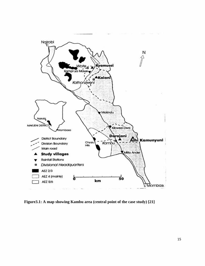
3.2 METHODOLOGY OF THE RESEARCH
Data and information for this project were collected through interviews with stakeholders and
visits of Jatropha production sites in Mtito Andei. The stakeholders who are engaged in initial
experiments of Jatropha and biodiesel production in Kenya include project developers such as,
NGOs and private companies, policy makers at relevant government ministries, and local
farmers and extension officers. The production sites that were visited included the villages of
Kibwezi District, Kambu Division e.g Ngwata, Nzambani, Mangelete in Mtito-Andei. Jatropha
production started since 2005-2006 in Kenya.
15
Figure3.1: A map showing Kambu area (central point of the case study) [21]

16
3.3 ECONOMIC VIABILITY OF BIODIESEL
Biodiesel production is considered to be economically viable when it is price competitive with
other Petroleum products. The cost of biodiesel production is greatly affected by the cost of
feedstock production. As the feedstock for biodiesel could be any vegetable or animal fat,
Jatropha oil is only economically viable when it is price competitive with available alternative
oils. This section first examines the viability of biodiesel production in the current Kenyan
market, analyzing the competitiveness of biodiesel with petroleum products and the market price
of Jatropha oil and seeds in Kenya. It then examines the profitability of Jatropha production as
biodiesel feedstock for smallholder farmers.
3.4 PRICE COMPETITIVENESS OF BIODIESEL
Jatropha was first introduced in Kenya in 2005, when local farmers started small-scale
production in the Districts of kibwezi, kitui, Makueni and Malindi.
There have been no actual sales of Jatropha oil in the Kenyan market at the time of the study
(March, 2012). In order to estimate the price of biodiesel in Kenya, the price of alternative
vegetable oils that are available was used as an indicator. Palm oil is assumed to be the main
alternative to Jatropha. Crude palm oil has been the major imported vegetable oil into Kenya for
the past decade in terms of both quantity and value. The commercial price of Jatropha oil is thus
expected to be less than that of crude palm oil. In 2012 the price of palm oil is 1,434,826 tons
($1.61 billion) that is about $1.122 per kg.
3.4.1 Price of Jatropha seeds and oil
In Kenya as by the consulted N.G.O (vanilla Jatropha) the price of 1kg of seeds is ksh.15 and
that of Jatropha crude oil is ksh.100 to big companies and ksh.60 for refined oil to Jatropha
farmers and the area community at large.
3.4.2 Jatropha biodiesel profitability production.
Currently three different modes of Jatropha production are taking place in Kenya: monoculture
mixed intercropping, hedges and intercropping with vanilla. In Kibwezi District where Jatropha
production has been introduced by non-governmental organizations, some farmers are converting
their farms into Jatropha plantations, although they intercrop Jatropha with other food crops for

17
the first year when Jatropha is relatively small. Some farmers with limited landholdings have
decided to experiment with growing Jatropha as a hedge. However, the majority of farmers in the
area are observing their neighbors‟ production of this new crop to see how profitable it will be.
3.5 EXPECTED YIELD
This section estimates the yield and expected revenues of Jatropha production and analyzes the
potential economic returns of adopting Jatropha production by smallholder farmers.
Jatropha yields depend on surrounding conditions i.e. varying climate, soil fertility, landform,
altitude, and water and fertilizer inputs.
Francis, Edinger and Becker [12] estimate the annual seed production per plant to range from
about 200 grams to more than 2 kilograms. Yield varies significantly depending on the water
input, which determines the number of fruiting period per year, which can vary from one to three
kilograms per tree. From the information taken from Kambu, Jatropha farmers harvest the plant
twice a year and one plant produces between 1kilogram of seed in the rainy season and about
500 grams during the dry season in the first three years. After 5 years, the production per tree
ranges from 1.2 kilograms under rain fed conditions to 3.2 kilograms under irrigated conditions.
There are two rainy seasons in Kenya, and the seasons and periods vary in each region. The
average annual rainfall during two rainy seasons is 329.3mm (April-June) and 372.4mm
(October-December) in Kibwezi District.hence more harvest is seen during this two periods.
.
3.6 REVENUE AND OPPORTUNITY COST OF JATROPHA PRODUCTION
Farmers‟ decisions on starting to farm Jatropha depend upon the returns that they expect to get.
In this section we compare the revenues that Kenyan farmers are likely to obtain by growing
Jatropha with the revenue streams and profit margins of other crops they can grow on the same
land. In Kibwezi the other cash crop that is mainly grown is a cow pea which only yields once a
year. It produces about 320-680 kilograms per acre.

18
Figure3.2: Cow peas grown at Kambu
Compared to Jatropha that produces 500 kilograms to 1000 kilograms per acre, hence Jatropha
would be an attractive crop to grow for smallholder farmers in Mtito andei.
3.7 CONTRIBUTION OF JATROPHA TO IMPROVEMENT OF LOCAL
LIVELIHOODS
There are two scenarios for introducing Jatropha production to local communities.
The first scenario is large-scale production where private enterprises take initiatives to produce
large amounts of biodiesel and local populations are incorporated into the production process as
wage laborers on plantations or contract suppliers of seed.
A second scenario is the case of small-scale decentralized biodiesel production. Local
populations grow Jatropha seeds which are collected through local collection systems, and
Jatropha biodiesel produced in small oil pressing and processing facilities. Facilities could be
operated by community groups, cooperatives or private enterprises. For example in Kambu
Vanilla Jatropha NGO has opened a seed collecting Centre where it has installed a pressing
machine that presses the seeds delivered by the farmers.
3.8 JATROPHA OIL LOCAL LIVELIHOOD IMPROVEMENTS
From the above discussion, it appears that the opportunity for local populations to maximize
benefits from Jatropha is to engage not only Jatropha production but also in oil extraction.

19
Locally extracted oil can be directly used in diesel engines or as a kerosene substitute for lamps
and stoves [11].
Jatropha oil is much less expensive than kerosene so its use could contribute to savings for local
communities and poor urban households. According to a survey administered to 2,300
households in 15 rural districts and five urban centers in Kenya by the Ministry of Energy in
2000, 82% of urban and rural households used kerosene for lighting in lanterns, tin lamps and
pressure lamps, and 88% used kerosene for domestic cooking. The kerosene consumption per
household in urban areas was an average of 90 liters per year compared with 41 liters per year in
rural areas, while per capita consumption was an average of 23 liters per year in urban areas and
8.6 liters per year in rural areas. Kerosene is mainly used for lighting in rural areas and for both
lighting and cooking in urban areas [12]. Despite the reliance on kerosene by low income
households, kerosene, like other petroleum products, has become less affordable for low income
population in recent years. The landed price of kerosene has gone up by 2.5 times from ksh.35
(2005) to ksh.85 (2012).
Jatropha oil might be most competitive with kerosene when produced in rural areas close to the
source of seed supply. Special lamps and stoves designed for Jatropha oil have been developed
and tested locally.
Figure3.3: Picture of the Jatropha oil lamp
The successful promotion of Jatropha oil for cooking depends on the availability and
affordability of other energy sources (e.g. fuel wood, charcoal, liquid natural gas, etc)

20
Currently, the most promising and well developed uses of Jatropha are for soap and candle
making.
3.6 GOVERNMENT POLICY ON JATROPHA BIODIESEL PRODUCTION FOR THE
IMPROVEMENT OF LOCAL LIVELIHOOD
Government policy plays an important role in fostering growth of the biodiesel industry. Active
government support has been essential in every country where biodiesel and other biofuel
industries have been successfully established.
By supporting the biodiesel industry, governments of oil-importing countries accrue benefits
such as increased energy self-sufficiency, foreign exchange savings, and income from the growth
of agricultural sectors and new biodiesel industries. As a country without proven petroleum
resources, Kenya‟s economy is vulnerable to increases in the prices of petroleum products
Governments must make careful decisions on whether the benefits from supporting the biofuel
industry would exceed the loss of government tax revenue that would result from lower imports
of petroleum products [13]. As in other oil importing countries, biofuel policy is under
discussion in Kenya.
In Kenya, various stakeholders in biodiesel industries formed the national biodiesel committee in
January 2006 under the Ministry of Energy to have a collective voice in promoting policies such
as blending mandates, tax mandates and production subsides [14].

21
CHAPTER 4: JATROPHA SEED OIL EXTRACTION AND CAKE
DRAINAGE SYSTEMS.
4.1 JATROPHA SEED OIL EXTRACTION
The major aim of all screw press machines is to generate compression for extraction of oil in the
seeds but there are several differences in design of the pressing shaft and drainage mechanism
principles. The oil presses used in industry are described in following subsections followed by
the mechanisms used in cake drainage.
4.1.1 Komet Oil Presses
In this type of screw press, oil leaks out from the holes as represented in Figure4.1. The holes are
drilled on the vessel. The oil drainage hole has a larger diameter outside the vessel and this
diameter continues up to few millimeter thickness of the vessel. This small thickness of the
vessel is drilled with a smaller diameter. Most probably, the reason for the short length of the
smaller hole is to prevent it from choking with cake. Also, oil drainage zone is far from the cake
drainage zone. At the cake drainage zone, cake pressure is maximum. So, if the oil drainage
holes were drilled close to the cake drainage zone, then the holes can be choked with cake easily.
Dry cake extrudes from the nozzle. At the cake drainage, there is a heating system. Heat provides
higher oil yield and lower residual oil in the cake. In this type of screw presses, different kinds of
seeds can be compressed by changing the nozzle and the rotational speed of the screw shaft. [16]
Figure4.1: Detailed Picture of Screw Press Manufactured by Oekotec, IBG-Monforts [16]

22
4.1.2 Rosedowns Oil Presses
A complete system of a Rosedowns screw press is represented in Figure4.3. The system is
divided into subgroups as:
4.1.2.1 Main Gearbox:
It transmits the power of the motor to the screw shaft. Gearboxes should be separated as far as
possible for the hot and dirty environment of the pressing sections. The feeding section of the
screw shaft is the cooler and lower pressure end of the press. Therefore the best choice for the
drive position is the feeding end of the screw shaft. [17]
4.1.2.2 Feeding Section:
It is composed of mainly three parts which are the feed inlet, the horizontal feeder and vertical
feeder. Seeds are poured into the feed inlet. Then with the help of the variable speed drive of the
horizontal feeder, the flow of feed is controlled. Vertical feeder prevents bridging in the cage
inlet and ensures that the seeds pass into the vessel. [17]
4.1.2.3 Bearings:
There are two kinds of bearings. One of them is called thrust bearing and it carries the thrust
loads generated by the press. The other bearing is the discharge end bearing and it is used for
supporting the shaft when there is no load or light load inside the press. Without this bearing, the
screw shaft can hit inside the walls of the vessel. [17]
4.1.2.4 Cages:
For longer presses, the cage is divided into two parts in order to keep the main cage to a more
manageable size for maintenance operations. The inside cage is composed of lining bars
separated by spacers. The size of the spacers can be altered for different kinds of seeds by
changing the drainage gaps. [17]
4.1.2.5 Screw Shaft:
The screw shaft is the key functional part of a screw press. The screw shaft has multi-stage
compressions in order to reduce the required pressure. In recent years the multi-stage, lower

23
compression screw shaft has led to significant improvements in performance, wear life and
power consumption. As represented in figure4.2, at the compression stage, the screw shaft
becomes tapered where the inside vessel diameter decreases. Therefore, pressure increases at the
decreased annular area which results in compression of seeds. [17]
Figure4.2: Detailed views of the screw shaft of Rosedowns Screw Presses [17]
Figure4.3: Detailed Drawing of Screw Press Manufactured by Rosedowns [17]
4.1.3 Vincent Screw Presses
As represented in Figure4.4, a screw of progressively reducing pitch rotates inside a cylindrical
perforated screen. Material entering the hopper is subjected to gradually increasing pressure as it
moves toward the exit end of the press, forcing the liquid phase to extrude through the screen.
Two resistor teeth fit in each interruption of the turn as seen in Figure 8. This interruption
prevents jamming. [18]

24
Figure4.4: Screw with Resistor Bars manufactured by Vincent Corporation [18]
4.1.4 Strainer type screw presses
In strainer type of screw presses, oil rushes out from the strainers which are made up of flat
plates mounted through the screw shaft. By rotating the arm which is at the right end of the
screw press in Figure4.5, the screw shaft can be displaced forward or backward to adjust the
thickness of the cake which is extruded at the left end of the screw press. Accordingly, different
kinds of seeds can be compressed also by changing the rotational speed. [19]
Figure4.5: Strainer Type Screw Press [19]

25
4.2 CAKE DRAINAGE SYSTEMS
The common property of cake drainage systems in screw presses is the adjustability of the cake
drainage opening. Narrower openings result in low residual oil content in the cake. Also, the
opening size depends on the type of the seed.
During our research, various types of cake drainage systems are considered. Some of them are
used in conventional screw presses as presented.
Working principles of these cake drainage systems are presented in the subsections.
4.2.1 Nozzle cake drainage system
Generally, in small types of screw presses, nozzle type choke mechanism is used. In Komet Oil
Presses, this type of a choke mechanism is used [16]. In nozzle type choke mechanisms in
figure4.6, one end of the screw shaft is free and the other end has two bearings. The screw shaft
is short enough to compensate any deformation arising from buckling.
Seeds continue to accumulate at the end of the screw until the maximum pressure has been
reached. During compression, oil part of the seeds leaks from the filter and the left cake starts to
extrude out from the nozzle, at the end of the screw. Besides, the required maximum pressure
can be provided by adjusting the nozzle diameter.
In this type of choking mechanism, the maximum pressure at the end of the screw pushes the
screw backward. The resultant force is the multiplication of the axial component of the
maximum pressure and the circular area of the screw.
Since the application area of the back force is comparatively larger than in conical type of choke
mechanisms, bearing which carries the axial back force should be larger in this type of systems.
Another disadvantage for this choking system is the probability of a blockage at the entrance of
the nozzle.
26
Figure4.6: Nozzle cake drainage system
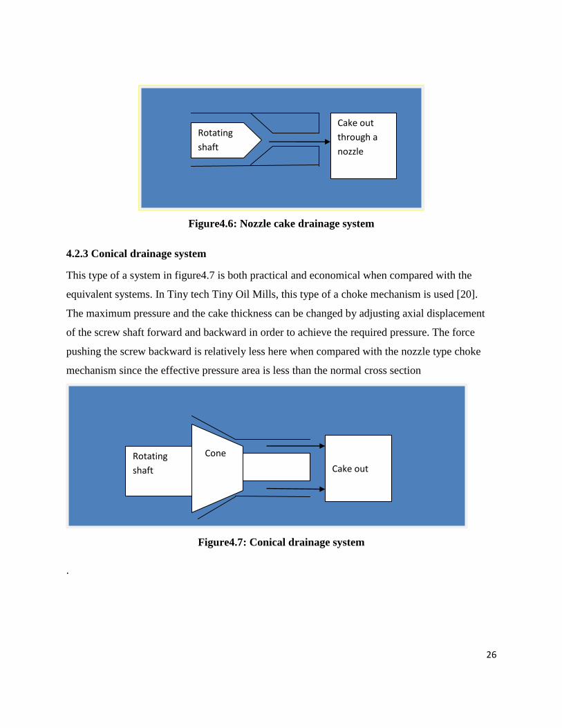
4.2.3 Conical drainage system
This type of a system in figure4.7 is both practical and economical when compared with the
equivalent systems. In Tiny tech Tiny Oil Mills, this type of a choke mechanism is used [20].
The maximum pressure and the cake thickness can be changed by adjusting axial displacement
of the screw shaft forward and backward in order to achieve the required pressure. The force
pushing the screw backward is relatively less here when compared with the nozzle type choke
mechanism since the effective pressure area is less than the normal cross section
Figure4.7: Conical drainage system
.
Rotating
shaft
Cake out
through a
nozzle
Rotating
shaft
Cone
Cake out

27
CHAPTER 5: PRELIMINARY AND DETAILED DESIGN OF THE OIL
EXTRACTION MACHINE
5.1 PRELIMINARY DESIGN
In this section, design tree and block diagram of the selected system, separation of the system
into subsystems and specifications of these subsystems are given.
5.1.1 Design Tree
In the design tree of the extraction machine, the system is separated into its subsystems to
analyze the design from top to bottom. Components of the Machine are represented. The screw
press is composed of skeleton, hopper and vessel, connection elements and drive system.
Skeleton carries the hopper and vessel body. Hopper is mounted onto the vessel. Drive system is
connected to the end of the screw shaft via a pulley. The shaft is held in position by two bearings
mounted on the skeleton
Components are represented in fig5.1
Figure5.1: Design tree
SKELETON
HOPPER VESSEL SCREW SHAFT CONE
TANK CAKE
28
Seeds are fed into the system from the hopper and pass through the screw shaft which
concentrically fitted into the vessel as oil drains out through the holes around the vessel and at
the end of the vessel the cake is drained out. The oil then drains into the tank placed just below
the vessel.
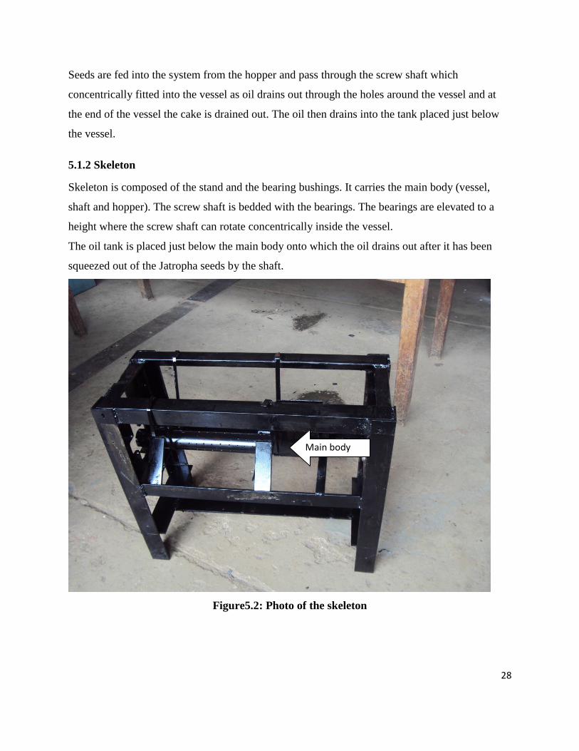
5.1.2 Skeleton
Skeleton is composed of the stand and the bearing bushings. It carries the main body (vessel,
shaft and hopper). The screw shaft is bedded with the bearings. The bearings are elevated to a
height where the screw shaft can rotate concentrically inside the vessel.
The oil tank is placed just below the main body onto which the oil drains out after it has been
squeezed out of the Jatropha seeds by the shaft.
Figure5.2: Photo of the skeleton
Main body

29
5.1.3 Main Body
The main body is composed of three parts which are the screw shaft, the vessel and the hopper.
Their functionalities are described in the following subsections.
5.1.4 Screw Shaft
The seeds are compressed in two ways. First way of compression occurs by the continuous
feeding of the seeds into the system. Newly fed seeds compress the seeds which are already
present in the system Another way compression takes place is between the inside surface of the
vessel and inside surface of the screw shaft. As the depth of the thread decreases continuously,
the distance between thread surfaces decrease as a result the seeds volume reduce as oil is
drained out. For these reasons, this type of screw shaft configuration is evaluated as the most
appropriate one for this project.
Screw shaft rotates inside the vessel. There is a small clearance between the vessel and the screw
shaft. This small clearance is necessary for avoiding the seeds penetrating between the outside
diameter of the screw shaft and the inside surface of the vessel. In such a case, friction force
between the screw shaft and vessel increases, and required torque becomes higher.
The screw shaft pitch reduces down the vessel as a result more pressure is applied on the seeds.
The seeds are fed at where the thread depth is maximum. As the seeds pass through the screw,
swept volume of each turn decreases. Under high pressure, oil is separated from the compressed
seeds and drains back to the previous turns at where the pressure is lower. Since cake has no
such fluidity property like oil, it continues to the end of the screw shaft and drained out as flakes.
At the end of the last thread on the shaft there is a cone which allows a narrow Cake to drain out
radially between it and the vessel surface. By adjusting the screw shaft in the longitudinal
direction, the gap size of the cake drainage can be reduced or increased. As the gap size is
smaller, the residual oil content of the cake becomes lower, because the compressed seed is
applied higher pressure

30
Figure5.3: Shaft
5.1.5 Vessel
The vessel has a rectangular hole which allows the seeds from the hopper into the beginning of
the screw shaft where the thread pitch is maximum. It has holes all round from which oil drains
out into the tank.
The oil drainage zone is slightly far from the cake drainage zone or in other words, the maximum
pressure zone. The reason is that, these small holes are filled and choked with compressed cake
at high pressure levels. However, on the mid zone of the vessel, pressure of the cake is not that
much high and oil can easily pass through these holes.
Figure5.4: Vessel
5.1.6 Hopper
Hopper is used to carry and canalize the seeds into the screw press. Feeding does not need any
energy; gravity is sufficient for feeding. It is a stationary part and mounted onto the vessel. The
passage hole of the hopper is large enough in order to prevent choking of the seeds into the
vessel.
Rectan
gular
ho
le

31
Figure5.5: Hopper
5.1.7 Tank
This is where the squeezed oil is drained to awaiting transfer to the storage containers. It is
placed just below the vessel and it contains lid which has many holes.
Figure5.6: Tank
5.1.8 Cone
The maximum pressure and the cake thickness can be changed by adjusting axial displacement
of the screw shaft forward and backward in order to achieve the required pressure. As a result the
amount of cake out of the cone is adjusted hence the maximum amount of fuel can be obtained.

32
Figure5.7: Cone
5.1.9 Drive system
This system comprises of a motor two horsepower, 2 pulleys (10cm and the other 250cm
diameter) and a v belt. The 250cm pulley is connected onto the pressing shaft while the other
10cm pulley is connected onto the motor shaft. The pulley connected to the pressing shaft is 25
times the diameter of the pulley connected to the motor shaft.

33
Figure5.8: Drive system
Pulley
V belt
Motor
Pulley

34
5.2 DESIGNED MACHINE OUTLOOK
Figure5.9 shows the oil pressing machine with all the parts described above assembled in it.
Figure5.9: Fully assembled machine

35
5.3 DETAIL DESIGN CALCULATIONS
5.3.1 Experiment 1: oil cake ratio of pressed seeds
An experiment was done to determine the ratio of a given volume of un-pressed seeds to the
volume of the pressed seeds.
Figure5.10: Experimental seeds pressing diagram
Using a pipe of length 152mm the seeds were put to a height of 84mm and then pressed using a
hand press until the new height of pressed seeds (cake) was found to be 15mm.
Hence the ratio of volume of un-pressed to pressed seeds
This ratio led to the design of the pressing shaft threads
Plunger
Pipe
Oil o
ut

36
5.3.2 Experiment 2: Determining the density of the Jatropha seeds
A jug of known dimensions was filled up with seeds and weighed
Results
Volume of the jug=0.00308m3
Weight of seeds =1.08kg
Hence density of seeds=3
Calculation of area of the shaft threads
Shaft diameter=25.4mm
Shaft with thread diameter=45.4mm
Hence the area of the shaft threads=
Taking the pitch of the first thread of the shaft to be 140mm the volume of the seeds crushed
when it is fully surrounded with seeds.
Area at entrance * pitch at entrance =
From experiment 1 the compression ratio was 1:6 but for complete compression of the seeds the
ratio was taken to be equal to1:7.
Hence the exit pitch length=140/7=20mm
Taking the pitch at exit to be 20mm
Volume at exit=
5.3.3 Calculation of revolutions per second of the pressing shaft.
Mass of seeds in entrance thread=density of seeds * volume at entry

37
=
From the project objective of designing a machine that can crush 100kg of seeds/hour
Writing in revs/second =
5.4 THREAD DESIGNING
Circumference of the 1inch diameter shaft=
Thread length for the first pitch of 140mm will be?
Figure5.11: How to generate thread profile at a pitch of 140mm
From Pythagoras theorem
Thread 2 to has a pitch of 120mm hence its thread length will be
80mm
140mm
Thread length profile

38
Figure5.12: How to generate the thread profile at a pitch of 120mm
From Pythagoras theorem
The table below summarizes the remaining thread profile lengths used for various pitches
Pitch (mm) Thread length (mm)
140 161.25
120 144.22
100 128.06
80 113.14
60 100
40 89.44
20 82.46
Table5.1: Summary of thread length profiles for given pitches
Thread length
profile
80mm
120mm

39
Resultant thread profile
Figure5.13: Resultant thread profile
5.5 HOW THE THREADS WERE PLACED ON THE SHAFT
An annular disc was cut out of a sheet metal. The inner diameter being the thread length while
the difference between the inner diameter and the outer diameter being the thread thickness.
Then the annular disk was cut and stretched on the thread profile as shown in the figure below.
Cut here
Figure5.14: An annular disk that was cut to form threads on the shaft
Resultant thread profile

40
After the disc has been cut it is stretched on the shaft as shown to form a thread on the shaft as
shown below.
Figure5.15: Showing how cut annular disc was cut to form threads
The inner diameter is given by using the thread length as the circumference of the disc
For example the annular disc for the first thread.
Circumference=161.25= πd
Therefore d=51.32mm
Stretch the annular cut disc Stretch the cut annular disc

41
A table giving details on how different materials were machined.
FIGURE PART NAME OPERATION
WIDTH ANGLE
LINE
It is made from Mild Steel.
Appropriate length cut on the power saw.
VESSEL The feed space for the seeds was cut on the
milling machine.
The holes were drilled on the pillar drill.
STAND ANGLE
LINE
It is made from Mild Steel.
Appropriate length cut on the power saw.
SHAFT The threads were Arc welded on the shaft
following a profile marked on the shaft.

42
MAIN BODY The hopper and the pipe were joined together
by Arc welding.
The hopper was carefully positioned on the
feed space.
LID Mild Steel sheet metal was used.
The holes were drilled using a Pillar Drill.
LENGTH ANGLE
LINE
It is made from Mild Steel.
The appropriate length was cut on the power
saw.
HOPPER Made from sheet metal appropriately cut.
It was joined by Arc Welding.
END PLATE Carefully cut on the Lathe machine to the right
dimensions.
It was then Arc welded on the pipe.

43
COUPLING It was cut using a Hack saw from a pipe.
The holes were drilled on the Pillar drill.
BEARING
SUPPORT
It was cut from sheet metal made from Mild
Steel using a Guillotine Machine.
TANK The sheet metal used to make it is Mild Steel.
The different parts were joined by Oxy-
Acetylene welding.
Table5.2: Typical parts of the machine

44
CHAPTER 6. DISCUSSION AND CONCLUSION
CASE STUDY
In Eastern province of Kenya in Kibwezi area, a small town known as Kambu was the centre of
our case study. Kambu is a semi-arid area with no substantial crop farming due to its
unfavourable climate which does not support the growth of most food crops. Most of the land in
this area is not cultivated and is mostly used for the pasture of domestic animals. The land
currently being cultivated is quite small and for the plants to grow there has to be some form of
irrigation. The plant that grows there in abundance is cow peas which are grown commercially.
Thus the general population of the area is poor due to lack of a sustainable economic activity
which generates a steady income for the locals. Also the rising cost of living due to inevitable
rise in fuel costs does not help alleviate the situation. The Jatropha curcas plant which has been
found to readily thrive in the area due to its preference to semi- arid conditions is the answer to
some of the problems in the area. The plant which can produce oil which can be converted to
biodiesel would give the area a clean and affordable source of energy for daily use by the locals.
It would also provide a source of income to the farmers by selling their otherwise valuable seeds
which would be used to make bio-diesel after the oil has been processed in a plant.
THE OIL PRESS MACHINE
Thus there was a need for small scale oil pressing machine which could be used to extract oil in
small quantities depending on the amount of seeds which a particular farmer has got. The
machine needed to be mobile such that it could be easily moved from one point to another. The
design of the machine was based on the fact that different farmers would have different
quantities of seed and thus the oil pressing machine needed to press a small amount of seeds or a
large amount of seeds if need be. The machine that was fabricated has a theoretical seed
pressing capacity of 100 kg/hour when it is running at a speed of 30 revolutions per minute and
its prime mover is a 2 horse power electric motor.

45
FABRICATION OF THE OIL PRESS MACHINE
Fabrication of the oil press machine was done in the University of Nairobi Mechanical
Engineering Workshop. Some of the materials needed for fabrication of the machine were
available in the workshop but most of the other materials were outsourced from hardwares and
scrap metal dealers the major material used was mild steel. The machines used to make the
machine components included lathe machines, milling machines, Guillotine machine, Pillar drill,
Folding machine, Arc welding machine and an Oxy-Acetylene gas welding machine.
The fabrication process was involving and we had to spend extra time in the workshop to ensure
that the components were completed on time. It took about six weeks to complete the various
components and finally assembly to complete the machine. The major challenge came during
assembly of the various parts to form a complete unit. Some of the components needed some
modifications like grinding or further machining to enable them to fit as expected initially. The
shaft and pipe assembly posed a major challenge when it came to assembling the two parts since
the clearances between the pipe and the shaft were too small. The bearings at each end of the
shaft mounted to the main body also brought forth major problems when it came to place the
shaft at a central position relative to the pipe for smooth running of the press since the height of
the pillow block bearing had to match the height of the centralizing bearing. Thus the pipe had to
be held at a constant position relative to the pipe and also the shaft had to be maintained at a
certain position lateral to the pipe and all this had to be maintained during welding of these parts
into position. Obviously this was a tedious process and it had to be redone several times before a
correct position could be attained so that the shaft would be able to move freely without having
any contact with the pipe to avoid locking of the system during operation.
Also due to the method of welding used to place the threads on the shaft which was by Arc-
welding the threads were not evenly shaped on the shaft due to extreme heat during the welding
which caused part of the threads to warp and also during cooling the threads assumed some
crooked positions which were otherwise corrected using a hammer and an anvil which did not
result in a very accurate profile of the thread.
The oil press machine needs a powerful prime mover with the necessary torque to create the
adequate pressures to ensure compression of the seeds to produce oil. The lack of adequate
resources handicapped us in terms of design of the gear system needed to transfer motion from
the prime mover to the shaft effectively. Gears are expensive to manufacture and equally

46
expensive to buy thus we opted to use a simple belt and pulley system which would be used to
transfer power from the prime mover to screw press.
ACTIVITY SIZE AMOUNT (Ksh)
Angle Beam 914 cm length, 2 inch beam 4,000
Cylinder 52 mm diameter, 762 mm length, class B 1,000
Shaft 762 mm length, 1inch diameter 600
2 Pulleys 25 cm diameter and 10cm dia. 1500
1 Belts V-belt, 12.5mm width ,1800mm and class
A17
4000
1 Motor 2horse power 10,000
Sheet Metal 1m by 1m, Gauge 16 3,800
2 Bearings and Fittings 1 in dia. 3,200
10 Bolts and Nuts M 10mm 500
Labour (15% total
expenses)
4290
TOTAL 32890
Table 5.3: The machine budget

47
TESTING OF THE OIL PRESS MACHINE
Testing of the oil press machine was done in the University Mechanical Engineering workshop
and harvested Jatropha Curcas seeds were used in the test run. The seeds which need to be steam
heated before undergoing pressing were soaked in water instead to prepare them for oil
extraction. The fabricated oil press machine was then connected to a lathe machine chuck by
means of a pulley and belt assembly which was used instead of a Motor which was not available.
In this assembly the machine pressed the initial seeds well and some oil could be seen dripping
from the pipe holes but as compression continued the shaft locked due to clogging near the cone
which was supposed to guide the already compressed cake outside the pipe. The belt and pulley
assembly cold not drive the shaft past this point and the belt started to slip on the pulley even
though the lathe was still driving the pulley.
The cone clearance was also a challenge since we could not exactly establish at the time the
correct clearance we should have left for optimum compression and at the same time it would be
enough for continuous flow of the compressed cake outside the pipe.

48
CONCLUSION
The objectives of the project which were design, fabrication and testing of an electric powered
Jatropha Curcas oil extraction set-up suitable for a remote setting and Technical and Economic
analysis of small scale farming of Jatropha Curcas were achieved.
The design of the oil extraction machine was primarily guided by the need to have the machine
operating in a remote setting but also for the machine to operate effectively it needs a reliable
and effective power source which is electric power. Thanks to the recent Government efforts in
rural electrification electricity would not be an issue for remote areas of the country. The
designed and fabricated oil extraction machine is ideal for the remote setting since it is mobile
and can be easily moved from one point to another, it is also made from local materials which
makes it easier to maintain and repair in cases where it breaks down. The fabricated machine has
a seeds pressing capacity of 100 kilograms in an hour while it is running at 30 revolutions in a
minute using a 2 horse power electric motor. This is quite a large capacity for a small scale
machine but the capacity could be changed accordingly depending on the type of seeds being
pressed by changing the rotating speed of the pressing shaft. The machine was tested and
actually pressed some seeds but clogging of the pipe and shaft assembly led to locking of the
system mainly due to lack of enough torque to press the seeds since we were using a belt and
pulley system and also the undetermined optimum clearance of the cone assembly on the shaft to
guide the pressed cake outside the pipe. Relevant recommendations were given in the discussion
to improve the design and overcome the problems currently experienced during testing of the
machine.
In the case study discussed in chapter 3 of the report a detailed Technical and Economic Analysis
of small scale farming of Jatropha Curcas was carried out in a small town in Eastern province
called Kambu in Kibwezi District. The analysis comprised of an Introduction introducing the
area, its population, farming practices and agricultural potential mainly focusing on the areas
currently under Jatropha farming. Also the price competitiveness of Bio- Diesel , expected yield,
revenue and opportunity cost of Jatropha production and Government policy on Jatropha bio-
diesel production are some of the topics discussed in the case study chapter. This gave us a clear
outline on what was happening on the ground and gave us guidance on how to go about the
whole oil production chain from having the Jatropha Curcas in the farm, harvesting it, extracting

49
the oil and finally making use of the oil in ways that will improve the economy of the local
community.

50
RECOMMENDATIONS
From the observations made during the test run of the oil press machine we propose the
following:
1. Design of an effective power transmission system from the prime mover to the pressing
shaft. Preferably using gears which have the capability of transferring large amounts of
torque compared to belt and chain drives.
2. Design of an adjustable cone and shaft assembly to be able to test for the optimum
clearance needed for the machine to produce the maximum amount of oil without
jamming the pressing shaft.

51
REFERENCES
1 Singh, R.N., D.K. Vyas, N.S.L. Srivastava and Madhuri Narra. 2007. “SPRERI
experience on holistic approach to utilize all parts of Jatropha curcas fruit for
energy.” Renewable Energy: in press: 1-6.
2. Van Eijck, Janske and Henny Romijn. 2008. “Prospects of Jatropha biofuels in
Tanzania: An analysis with Strategic Niche Management.” Energy Policy 36: 311-
325.
3. Henning, R. 1996. “Combating Desertification: The Jatropha Project of Mali,
West Africa, in: The Arid Lands Newsletter” Accessed at:
<http://ag.arizona.edu/OALS/ALN/aln40/jatropha.html>
4 Openshaw, Keith. 2000. “A review of Jatropha curcas: an oil plant of unfulfilled
promise.” Biomass and Bioenergy 19: 1-15.
5. Kumar, Ashwani and Satyawati Sharma. 2008. “An evaluation of multipurpose oil
seed crop for industrial uses (Jatropha curcas L.): A review.” Industrial Crops and
Products: in press: 1-8.
6. Calvin, M.(1985). Fuel Oils from Higher plants: Prepared for the U.S. Department
of Energy.
7. Shah, Shweta, Aparna Sharma, and M.N. Gupta. 2005. “Extraction of oil from
Jatropha curcas L. seed kernels by combination of ultrasonication and aqueous
enzymatic oil extraction.” Bioresource Technology 96: 121-123.
8. Jatropha Curcas - Multipurpose plants and Source of Energy for Future by, Edgar
Munch and Joachim Kiefer (GTZ).
9. Forson, F.K., E.K. Oduro, E. Hammond-Donkoh. 2004. “Performance of Jatropha
oil blends in a diesel engine.” Renewable Energy 29: 1135-1145.
10. Tamalampudi, Sriappareddy, Mahabubur Rahman Talukder, Shinji Hama, Takao
Numata, Akihiko Kondo, and Hideki Fukuda. 2008. “Enzymatic production of
biodiesel from Jatropha oil: A comparative study of immobilized-whole cell and
commercial lipases as a biocatalyst.” Biochemical Engineering Journal 39: 185-
189
11. Heller, J., 1996. Physic nut. Jatropha curcas L. Promoting the conservation and
use of
underutilized and neglected crops. 1. Institute of Plant Genetics and Crop Plant
Research,

52
Gatersleben / International Plant Genetic Resources Institute, Rome.
12. Kenya, 2002e. Study on Kenya‟s energy demand, supply and policy strategy for
households,
small scale industries and service establishments. Final report, September. p.16.
Ministry of
Energy, Government of Kenya, Nairobi.
14. Kituyi, E., 2006. Towards Sustainable Production and Consumption of Biofuels in
Kenya:
Some Issues to Consider. Discussion paper, Vol. 1 No.1. November,
Environmental
Chemistry Division, University of Nairobi, Nairobi.
15. Henning, R.K., 2002. Using the Indigenous Knowledge of Jatropha. The use of
Jatropha
curcas oil as raw material and fuel. Local Pathways to Global Development.
Indigenous
Knowledge Notes, 47, August. The World Bank, Washington, D.C. Available at:
http://siteresources.worldbank.org/EXTINDKNOWLEDGE/Resources/iknt47.pdf.
16. Webpage of IBG Monforts Oekotec GmbH & Co. KG,
http://www.oekotec.ibg-monforts.de, Accessed at 18.04.2012
17. Webpage of De Smet Rosedowns, www.rosedowns.co.uk, Accessed at
18.04.2012
18. http://vincentcorp.com, Accessed at 20.04.2012
19. Ferchau, E., “Equipment of Decentralized Cold Pressing of Oil Seeds”,
2000, Webpage of Folkecenter For Renewable Energy, www.folkecenter.dk
20. Webpage of Tinytech Plants, http://www.tinytechindia.com/oil.htm,
Accessed at 20.04.2012
21. Gichuki, F.N. (2000a) „Makueni District profile: Farm development, 1989-98‟,
Drylands Research Working Paper No. 1. Drylands Research, Crewkerne,
United Kingdom.
22 Webpage of
vanillajatrophafoundation,http://www.jatrophavanillafoundation.com//album.htm,
Accessed at 16.05.2012

53
APPENDIX A
All dimensions in millimeters

54

55

56

57

58

59
0

60

61

62
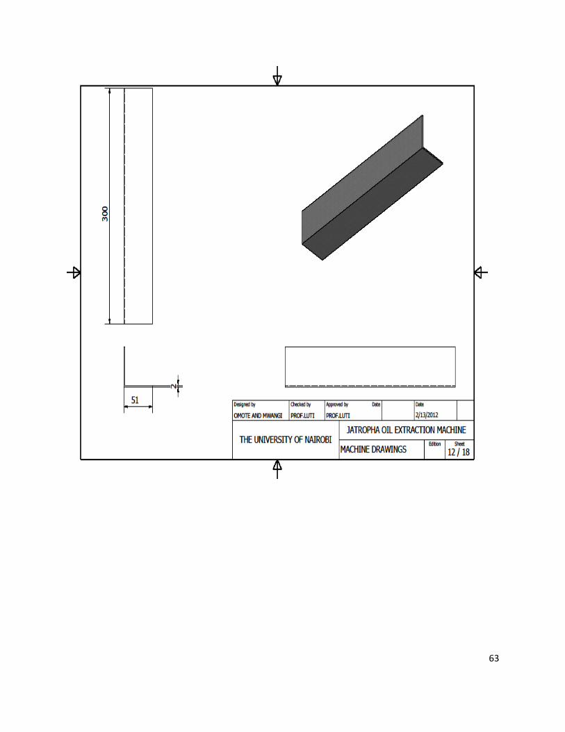
63

64

65

66

67
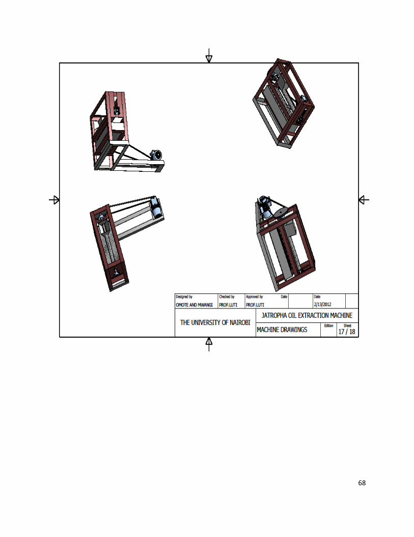
68

69

70

71
APPENDIX B
MACHINE PHOTOS
SIDE VIEW

72
PLAN VIEW

73
SIDE VIEWS

74
TANK