us department of agriculture vehicle barriers: their … dimas, ca 91773-3198 ... director, office...
TRANSCRIPT

Vehicle Barriers:Their Use and Planning Considerations
US Department of Agriculture
Forest Service
National Technology & Development Program
2300—Recreation Mgmt0623 1201—SDTDCJune 2006

Vehicle Barriers: Their Use and Planning Considerations
Ellen Eubanks , Landscape Architect
USDA Forest ServiceSan Dimas Technology and Develoment CenterSan Dimas, CA 91773-3198
June 2006
Information contained in this document has been developed for the guidance of employees of the U.S. Department of Agriculture (USDA) Forest Service, its contractors, and cooperating Federal and State agencies. The USDA For-est Service assumes no responsibility for the interpretation or use of this infor-mation by other than its own employees. The use of trade, firm, or corporation names is for the information and convenience of the reader. Such use does not constitute an official evaluation, conclusion, recommendation, endorse-ment, or approval of any product or service to the exclusion of others that may be suitable.
The U.S. Department of Agriculture (USDA) prohibits discrimination in all its programs and activities on the basis of race, color, national origin, age, disabil-ity, and where applicable, sex, marital status, familial status, parental status, religion, sexual orientation, genetic information, political beliefs, reprisal, or because all or part of an individual’s income is derived from any public assis-tance program. (Not all prohibited bases apply to all programs.) Persons with disabilities who require alternative means for communication of program infor-mation (Braille, large print, audiotape, etc.) should contact USDA’s TARGET Center at (202) 720-2600 (voice and TDD). To file a complaint of discrimina-tion, write USDA, Director, Office of Civil Rights, 1400 Independence Avenue, S.W., Washington, D.C. 20250-9410, or call (800) 795-3272 (voice) or (202) 720-6382 (TDD). USDA is an equal opportunity provider and employer.


v
Table of Contents
FORWARD ......................................................................................................................................... 1
INTRODUCTION ................................................................................................................................ 1
GENERAL DISCUSSION ................................................................................................................... 2
Barrier Types
Bollards ....................................................................................................................... 3
Fences ......................................................................................................................... 4
Gates ........................................................................................................................... 6
Large Rocks ................................................................................................................ 9
Wooden Guardrails ..................................................................................................... 9
Construction Drawings
Bollards ..................................................................................................................... 11
Fences ....................................................................................................................... 17
Gates ......................................................................................................................... 23
Guardrails .................................................................................................................. 49
Large Rocks .............................................................................................................. 65
DEFINITIONS ................................................................................................................................... 68
WEB SITES ...................................................................................................................................... 69
Acknowledgements ............................................................................................................... 69
APPENDIX A
Trail OHV-Width Limiter Gate and Nonmotorizd Trail Barriers .............................................. 70
APPENDIX B
Object and Barrier Markers on OHV routes .......................................................................... 73


1
FORWARDThis publication discusses vehicle barrier types, appropriate uses, and planning considerations. All barrier construction drawings are in the document, other full sized drawings are on the U.S. Department of Agriculture (USDA) Forest Service, San Dimas Technology and Development Center (SDTDC) Intranet site:
http://fsweb.sdtdc.wo.fs.fed.us/. These barriers do not take the place of high-way vehicle barriers or safety barriers on roads.
Use the vehicle barriers described in this publication at forest and grassland trailheads, picnic areas, and campgrounds, and at other facilities where vehicle control is needed to protect natural resources and amenities. This publication is written for designers, managers, recreation and engineering staffs, trail maintenance crews, and organized volunteer trail crews.
During the planning stage—and before installing a barrier—consult the Manual on Uniform Traffic Devices; FSH 7709.59, Chapter 10, Transportation System Operations Handbook, the off-highway vehicle (OHV) policy; and EM-7100-15, Sign and Poster Guidelines for the Forest Service for proper signing (travel management signs) and safety requirements for barriers. (See appendix B.) Also, use these USDA Forest Service and U.S. Department of Transportation, Federal Highway Administration Web sites:
http://mutcd.fhwa.dot.gov/,http://fsweb.wo.fs.fed.us/eng/programs/signs.
htm (see pages 11 through 15 for specifics on using “Road Closed” signs),
http://fsweb.mtdc.wo.fs.fed.us/php/library_card.php?p_num=0371%202812,
and http://fsweb.r1.fs.fed.us/e/access_and_travel_
mgmt/atm_index.shtml. (Scroll down to Field Implementation, click on ATM Signing.)
FORWARD/INTRODUCTION
INTRODUCTIONEach year a greater number of visitors in vehicles use the national forests and grasslands, which increases the need for vehicle barriers. Barriers are one way to define vehicle access and to restrict vehicle encroachment. The degree to which barriers block vehicles varies (figures 1 and 2).
Figure 1. Telephone pole guardrail.
Figure 2. Steel framed width-limiter gate. This gate allows certain width vehicles through.

2
GENERAL DISCUSSIONBarrier design depends on an area’s intended use (for example, OHV use or day use for picnicking); the area’s native materials; the Recreation Opportunity Spectrum (ROS) classification; and the Built Environment Image Guide (BEIG) character type (see Definitions on page 76). Designers and site managers decide appropriate materials and placement of barriers.
Consider vandalism as a factor in barrier planning. Generally, wooden barriers are more at risk because wood is used for campfires or carving projects. Concrete barriers, although more durable, easily succumb to vehicle ramming or chipping from sledge hammers. Often metal is used as the rail portion of a barrier and is at risk from vehicle ramming, too.
Some barriers keep vehicles within defined spaces such as on a road, within a spur, or in a specific parking area. (See figure 3.) Others are meant to deter access to a road or trail. Most visitors recognize and respond to clues and design features such as a simple curb. Use curbs to deter the majority of visitors from driving off-road. Curbs made of concrete or asphalt fit urban or rural ROS classifications while logs, native rock and stones, or mounded dirt act as curbs in less developed ROS classifications. (See figures 4 and 5.)
Figure 3. These 4- by 4-inch timbers are wheel stops that indicate parking spaces.
Figure 4. An extruded curb in a highly developed recreation site.
Figure 5. This rustic curb outlines a road.
Plan for the strongest barriers in areas where there have been vehicle control problems and, in some cases, fabricate specialized barriers for the vehicle type one is trying to control. (See figures 6 through 8.) In general, the larger the vehicle and the more aggressive the driver, the stronger the barrier needs to be. To make barriers more difficult to remove, use:
• Steel instead of wood.• Small boulders. • Larger diameter posts. • Posts buried deeper.• Posts set in concrete.• Posts anchored with rebar spikes.
GENERAL DISCUSSION

3
Figure 6. This wood post and rail fence surrounds a picnic area.
Figure 7. This width-limiter gate not only establishes the vehicle size that can be on the trail, it also marks the forest boundary.
Figure 8. This wood post and steel pipe rail fence keeps motorcycles and ATVs on the road and off the grass. Note the trail entrance in the background.
To anchor a 3- to 6-inch-diameter post, insert a rebar spike (longer than the post is wide) through the post near its bottom edge and set the post in concrete. If an area has small-diameter trees, use two or three posts together to form a stronger post rather than one large post that is out of scale for the area.
Barrier TypesGenerally, barriers are divided into five types: bollards, fences, gates, large rocks, and wooden guard-rails. The barrier size and its material(s) vary depending on the problem’s severity and the proper scale to fit with the site’s resources. Combine materials. For example, use a wooden post and a steel rail or plastic lumber made of recycled plastic. The U.S. Department of the Interior’s Yosemite National Park uses plastic lumber posts with wooden rails.
BollardsA bollard is a large post with no stringer or rail, commonly 1- to 4-feet tall, and used singly or grouped. (See figures 9 through 11.)
Figure 9. Bollards define the site’s edge and separate the road and the parking lot.
Barrier Types

4
Figure 10. Bollards outline the roadway, spurs, and campsite areas.
Figure 11. Bollards keep vehicles away from the restroom.
Purpose: Bollards block vehicle entry.
How to use: Use bollards to define edges such as the edge of a campground road, parking lot, or pedestrian entrance. When bollards define a pedestrian entrance, space them 32 inches apart to allow pedestrian and wheelchair passage; when they define a boundary, space close together.
Where to use: Use at developed sites with urban and rural ROS classifications.
Materials: Make bollards out of wood, concrete, steel, or plastic lumber posts.
Construction techniques: Follow instructions for a fence post.
FencesA fence is a structure functioning as a boundary or barrier, usually made of posts, boards, wire, or rails.
Purpose: Fences keep people and stock in or out of an area. Fences are not designed to withstand vehicular impact.
How to use: Combine fences with a curb, bumper stop, wheel stop, or shrubbery to prevent vehicle intrusion.
Where to use: Use fences for developed sites with urban, rural, and roaded natural ROS classifications. In wide-open spaces, use fences to line roads and trails to protect pastures and natural resources.
Materials: Use wood, metal, or plastic lumber in developed sites. On range lands, a wooden post or steel t-post and wire fence is common. Openings between the wire strands of the fence allow small animals to go through the fence. A fieldstone wall—or rock fence—is appropriate in all ROS classifications, if the rock is local.
Construction techniques: Pound steel t-posts into the ground or dig in a wooden post. String with wire or barbed wire (depending on animal type) and use a come-along to tighten the wire strands. See figures 12 through 15. The following Web site has wire-fence details:
http://www.de.nrcs.usda.gov/technical/technical_references/engineering/eng_
drawings.html
This Web site has information on fieldstone fences
http://www.dswa.org.uk/Publication_frames_page.htm.
Note: If the fence spans a stream or dry wash, use a three-strand wire fence to ensure passage of floodwater and debris.
Barrier Types

5
Barrier Types
Figure 12. Wooden and steel t-post wire fence.
Figure 13. Wooden fence with two strands of barbed wire.
Figure 14. Double post stacked rail fence.
Figure 15. This low wall is held together with mortar; it is similar to using fieldstones to build a rock fence

6
GatesGates allow passage; they may or may not swing open. (See figure 16.) Secure gates to a fence or a substantial natural feature to prevent people from driving around them.
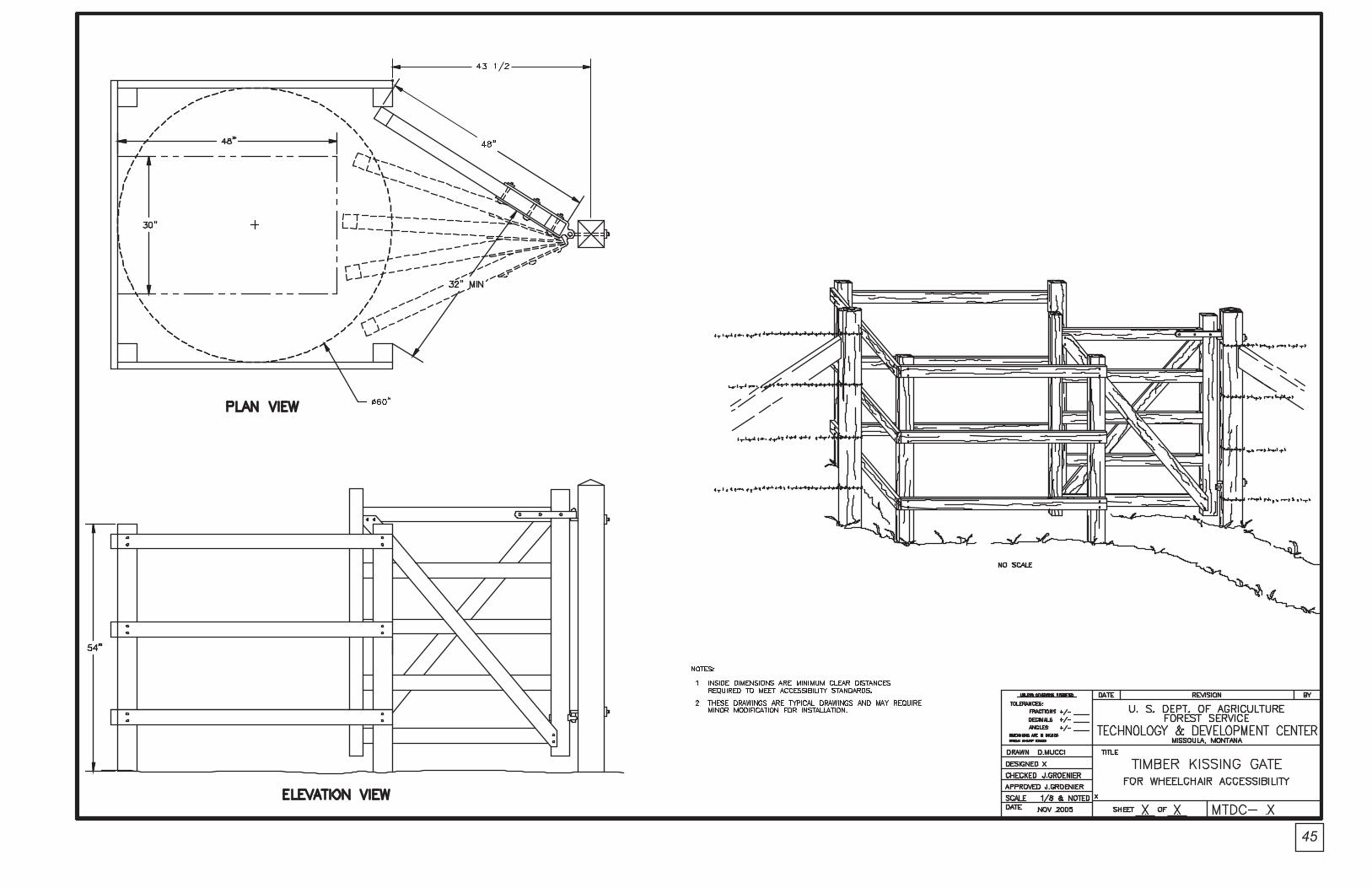
Figure 16. Schematic of kissing gate—designed to allow wheelchair access while blocking ATV access.
Accessible Kissing Gates Purpose: The accessible kissing gate has two openings: a swing gate secures one opening while a person passes through the other. This gate allows wheelchair access and blocks motor vehicle access, including all-terrain vehicles (ATVs).
How to use: Use for pedestrian and wheelchair access, while blocking stock, motorcycle, and ATV access.
Where to use: Use at an accessible site. This gate requires flat ground, an area at least 7-1/2-feet square for the gate, and an additional area for entry and exit paths.
Materials: Build the kissing gate out of wood or steel.
Construction techniques: See construction drawings and the USDA Forest Service Missoula Technology and Development Center’s 2006 publication Accessible Gates for Trails and Roads by James “Scott” Groenier.
http://fsweb.mtdc.wo.fs.fed.us/
Right-angle GatesPurpose: A right-angle gate creates a passageway for pedestrians and stock. (See figures 17 and 18.)
Figure 17. This wooden fence includes two right angle turns. The width of the opening is a maximum of 32 inches (nonaccessible).
Figure 18. This gate has a single right angle turn and may not be as effective at keeping motorcycles out of an area.
Barrier Types

7
How to use:
• Use a u-turn opening with two right-angle turns, which prevent motorized vehicle entry. A vehicle is blocked because the vehicle is either too wide or too long to make the right-angle turns required for passage. This is not an accessible gate.
• Use a one right-angle turn opening to keep out vehicles. This is not as effective as a u-turn pattern.
Where to use: Use where motorized vehicles are prohibited.
Materials: Use wood, steel, or a combination of both.
Construction techniques: Use wooden or steel posts with wooden or pipe rails. See construction drawings.
Steel Road Gates Purpose: Steel road gates prevent vehicle entry to roads, trails, and other closed areas, such as administrative roads and campgrounds. (See figures 19 and 20.)
Figure 19. Standard Angeles National Forest road gate. Note that large rocks and berms have been placed to block entry around the gate.
Figure 20. This double gate is used at an OHV area.
How to use: Close and lock the gate.
Where to use: Use at the entrance to a road or facility.
Materials: Use steel pipe to form posts and steel guardrail material or pipe to form the rails. Attach a travel management sign.
Construction techniques: See construction drawings.
Steel Trail Gates 1. Width-Limiter Gate
Purpose: This gate prevents certain width vehicles from entering. (See figure 21.)
Figure 21. This width-limiter gate is used at trailheads to block certain vehicle types and to allow access by other types. A cross-bar is in place to close the trail to all uses.
Barrier Types

8
How to use: Use this gate to limit the access of four-wheel drive vehicles and ATVs while allowing motorcycle access. (The 27-inch gate is not accessible.)
Where to use: Use at the entrance to a trail or facility. This gate needs to be visible at the trailhead and as one approaches while riding. For safety reasons, do not let the gate completely blend in or disappear into the landscape. On the other hand, do not let it be a focal point from a distance.
Materials: Use steel pipes or used steel well casings.
Construction techniques: See written fabrication instructions, and construction drawings.
2. Nonmotorized Trail Barrier (Stock) GatePurpose: This gate allows stock and pedestrians on trails. (See figures 22 through 25.) This gate is not accessible.
Figure 22. This nonmotorized trail barrier gate allows pedestrians and stock to pass through. The gate is flanked by a steel rail fence to prevent people from skirting the gate.
Figure 23. This nonmotorized trail barrier gate is shown with the upper bar closed, closing the trail to all traffic. A wire fence is attached to the gate to prevent people from skirting the gate.
Figures 24 and 25. A barbed wire fence is strung through the holes on the flange on the side of the post. This prevents people from skirting the gate.
How to use: Use at trail entry. Motorized vehicle entry is impossible without heavy weight lifting (vehicle) or destruction of property (government).
Where to use: Use at the entrance to a trail or facility and where trail use designation changes. Tie gates to a fence or a substantial natural feature to prevent people from driving around them.
Barrier Types

9
Materials: Use steel pipes that will withstand vehicle and equestrian bumps.
Construction techniques: See photographs, construction drawings, and narrative in appendix A.
Large RocksRocks are difficult to drive over in a standard automobile and most drivers would not try. However, OHV users may view the rocks as a challenge. (See figure 26.)
Figure 26. These grouped rocks were placed to protect a fire hydrant.
Purpose: Large rocks prevent people from parking off the pavement and keep drivers within designated parking areas. Rocks block entry to decommissioned roads and trails.
How to use: Mimic nature by planting rocks in clusters of one to five and varying space between the rocks and the clusters. End a cluster of rocks where there is sufficient vegetation to prohibit vehicle entry.
Where to use: Use where large rocks occur naturally. If large rocks are not common, do not use them; they will appear out of place.
Materials: Use barrier rocks that weigh 200 to 400 pounds each.
Construction techniques: Bury one-third of the rock for stability, anchoring, and a more natural look. See drawings.
Wooden GuardrailsWooden guardrails are a series of low posts tied together by wooden rails.
Purpose: Guardrails block and control vehicular access. (See figures 27 and 28.)
Figure 27. This guardrail delineates a parking lot.
Figure 28. Close up view.
How to use: Combine guardrails with a curb, bumper stop, wheel stop, or shrubbery to increase effectiveness against vehicle intrusion.
Where to use: Use them to line roads or areas, such as trailheads or turnouts, in urban and rural ROS classifications, and in limited areas in a roaded natural ROS classification.
Materials: Combine materials, such as concrete posts and wooden rails.
Construction techniques: See photographs and construction drawings, which include a no-dig barrier.
Barrier Types

10
Construction DrawingsThe following drawings show many different barriers. Some were described previously, others were not. The drawings are divided into five types: bollards, fences, gates, large rocks, and wooden guardrails.
Construction Drawings

BOLLARDS


13
1-1/2" CHAMFER
1-1/2"
ELEVATION
PRECAST CONCRETE POST
8"
5"1-1/2"
1-1/2" CHAMFER
1-1/2"
6"
3'-6
"
2" CLEAR#3 REBAR
PLAN
5"
8"
1-1/
2"
1-1/2"
PLASTIC OR ELECTRICAL2 EACH 1" x 8" DIA. PIPE,
1-1/2" CHAMFER6"
CONDUIT SLEEVE
4"
1-1/
2"5"
8"

14
7"8
1/2"
8 1/
2"
8 1/2"5"8 1/2"
4" x
6"
x 5'
TR
EA
TE
DT
IMB
ER
PO
ST
(P
OS
TT
O F
IT IN
SID
E S
TE
EL
TU
BE
)
CO
NC
RE
TE
FO
OT
ING
TR
IM P
OS
T T
O F
ITIN
SID
E S
TE
EL
TU
BIN
G
1/2"
DIA
. x 7
" B
OLT
W/
NU
T &
WA
SH
ER
S (
FO
RS
UP
PO
RT
OF
TIM
BE
R P
OS
T)
OP
EN
AR
EA
FO
R D
EB
RIS
6" x
4"
x 3/
16"
ST
RU
CT
UR
AL
ST
EE
L T
UB
ING
6" x
4"
x 3/
16"
ST
RU
CT
UR
AL
ST
EE
L T
UB
ING
1/2"
DIA
. x 7
" B
OLT
W/
NU
T &
WA
SH
ER
S (
FO
RS
UP
PO
RT
OF
TIM
BE
R P
OS
T)
45°
CH
AM
FE
R
1/2"
NO
TC
H
4" x
6"
x 5'
TR
EA
TE
DT
IMB
ER
PO
ST
1 1/
2" D
EE
P H
AN
DLE
PO
CK
ET
5 3/
4" x
9"
ME
TAL
PLA
TE
WIT
H 1
80°
HIN
GE
4" x
4"
PLA
TE
PA
DLO
CK
(G
OV
ER
NM
EN
TF
UR
NIS
HE
D)
1/2"
x 6
" B
OLT
WIT
H"V
AN
DA
LEG
AR
D N
UT
"
CO
NC
RE
TE
FO
OT
ING
4"
WIT
H S
TAP
LE
FIN
ISH
ED
GR
AD
E
6"
2" x
21"
x 1
/2"
RO
UT
ED
RE
CE
SS
FO
R "
NO
PA
RK
ING
" S
IGN
1'-4 1/2"
1 1/
2"
1'-0"
2"
3"
2'-0"
4"
PLA
NS
TE
EL
SLE
EV
E D
ETA
IL
ST
EE
L T
UB
E D
ETA
IL
FR
ON
T E
LEV
AT
ION
SID
E E
LEV
AT
ION
1/2"
DIA
. x 7
" B
OLT
W/
NU
T &
WA
SH
ER
S (
FO
RS
UP
PO
RT
OF
TIM
BE
R P
OS
T)
6" x
4"
x 3/
16"
ST
RU
CT
UR
AL
ST
EE
L T
UB
ING
6"

15
4'-0"
2'-6"
MA
X. S
IZE
1-1
/2"
5" C
RU
SH
ED
GR
AV
EL
TH
EM
E O
R E
NV
IRO
NM
EN
T.S
TAIN
TO
MA
TC
HLE
AV
E N
AT
UR
AL
OR
DO
UG
LAS
FIR
PO
ST.
PR
ES
SU
RE
TR
EA
TE
D
MA
X. S
IZE
1-1
/2"
3" C
RU
SH
ED
GR
AV
EL
CO
MP
AC
TE
D N
AT
IVE
SO
IL.
OR
EN
VIR
ON
ME
NT.
TO
MA
TC
H D
ES
IGN
NA
TU
RA
L O
R S
TAIN
FIR
PO
ST.
LE
AV
ET
RE
AT
ED
DO
UG
LAS
SA
WN
PR
ES
SU
RE
1'-6"
OP
TIO
NA
L: 8
" -
10"
DIA
.
TYP 1/4"
2"
FIN
ISH
GR
AD
E
1 1/
4" 4
5° C
HA
MF
ER
8X8X
4'-0
" R
OU
GH
1. P
LAC
E P
OS
T B
AR
RIE
RS
2'-0
" M
INIM
UM
FR
OM
ED
GE
OF
TR
AV
ELW
AY
S.
NO
TE
S:
WO
OD
PO
ST
OR
BO
LLA
RD


FENCES


19
Fieldstone Fence Examples
These drawings were made available by the Drystone Conservancy. Specifications for these walls are available in leaflets at: http://www.dswa.org.uk/Publication_frames_page.htm. In the United States these types of walls are referred to as fieldstone fences.
Standard Walls
Coping
Throughs
HeartingFootings
2“ - 3”
Face stones
Bottom width 1’-8” to 3”depending on type of stone.
2‘

20
Single Wall
Cotswold Wall
Clawdd Wall
Cornish Hedge

GATES


.
ANGELES NATIONAL FORESTU.S. DEPARTMENT OF AGRICULTURE FOREST SERVICE
DESIGNED DRAWN
TECHNICIAL APPROVAL:
BYBY
TITLECHECKED
TITLETITLE
DATEDATE
DATEDATE
SHEET OF
CONTROL NO.REV. DATECROWN COMPLEX ROAD REHABILITATION
ROAD CLOSURE GATE DETAILS 6 7
23
32"
DIA
.
24"
DIA
.
24" TRAVEL WA 24"
GATE WIDT
NOTE: LOCKING POSTS, ONE EACH, WILL BE REQUIRED AT THE OPEN AND CLOSED POSITIONS OF THE GATE
PLAN VIENot to Scale
1
CONCRETE FOOTINGCONCRETE FOOTIN
6"36
32"
TRAVEL WA
GATE WIDT
48”
2"
50”
96”
CONCRETEFOOTING
ELEVATIONot to Scale
2
ROAD
CLOSED
1/2” X 18” DIA. STEEL PLATE
HINGE POST - 6-5/8” O.D. x 0.432 PIPE
1/2” X 18” DIA. STEEL COLLAR 6” DIA.HAND HOLE
LOCKING POST - 8-5/8” O.D. x 0.322 PIPE(CONCRETE FILLED AS SHOWN)
GATE ASSEMBLY - 8-5/8” O.D. x 0.322 PIPE
REFLECTOVIZED RED & WHITE TAPE
Y
H
"
Y
H
W
N
G
DETAILS-GATE ATTACHMENT3
Not to Scale
SECTION @ HINGE POST6
Not to Scale
HINGE POST PIPE6-5/8" O.D. x 0.432
GATE ASSEMBLY PIPE8-5/8" O.D. x 0.322
1/2" x 3" SHIM WELDS (8)
1/2" x 15"Ø STEEL COLLAR WELDEDTO GATE ASSEMBLY (BOTTOM)
NYLON WASHER
BREAKOFFGROOVE
BREAKOFFHEX HEAD NU
1/2” Ø x 12" LG. ROUNDHEAD VANDAL-TYPE BOLT
W/ATTACHED NYLON WASHER(2 BOLTS PER SIGN)
1/4" STEEL PLATE x SIGN SIZE
SIGN, BARRICADE, OROBJECT MARKER
3/8
S
T
1/2
9
6"15
3" 1"
3"
ISOMETRIC-LOCKING SYSTEMNot to Scale
4
Not to Scale
ISOMETRIC-LOCKING POST8
1/2" x PIPE Ø STEEL PLATE(WELDED TO POST TOP)
CUT-OUT FOR LOCKING PLAT
6"Ø HAND HOL
8-5/8" O.D. x 0.322 PIPE
LOCKING PIN W/ 1/2"Ø HOLE
15" x 3" x 1" STEEL PLATEW/SLOT FOR LOCKING PIN
3/8”
3"
3/8
Not to Scale
SECTION THRU LOCKING POS5
1/2" x PIPE Ø STEEL PLATE
LOCKING POST
15" x 3" x 1" STEEL LOCKING PLATE
4"
T
E
E
3"3"
3"3"
4848
"
96
3/8
3/8
NOTES:
Not to Scale
DETAIL-HINGE POST7
1/2" x 3" SHIM WELDS (8)
1/2" x 15"Ø STEEL COLLAR
6-5/8" O.D. x 0.432 PIPE
1/2" x 18"Ø STEEL PLATE
PIPE SHALL MEET THE REQUIREMENTS OF ASTM A 53, GRADE B. PIPE SI
CONCRETE SHALL BE IN ACCORDANCE WITH THE REQUIREMENTS OF SPECIFICATION SECTION 601.
GATE AND LOCKING POSTS SHALL BE PRIMED (1 COAT) AND PAINTED (2 COATS), COLOR WHITE, IN ACCORDANCE WITH SECTION 708-PAINT AFTER FABRICATION.
"
"-
-
ZE SHALL BE AS SHOWN ON THE DRAWINGS1.
2.
3.
3/8”
3/8”
3/8”
46” 3/8”
38-1/8”
3/8”
3/8”
3/8”
24”
9-7/8”
1-1/2”1/2”
3/4”
1-1/2”
10-5
/8”
3/4”
1-3/4”
15”
"
"


25


27

28

29


31


33


PR
-GA
TE
.DW
G
RE
V.
1/97
LOCKING POST UPRIGHT (NOT TO BEANCHORED IN CONCRETE, DRILL HOLESTO ACCOMODATE SLIDE LATCHES).
DISTANCE AS REQUIREDTO LOCK GATE INTOPOSITION
VARIABLE OPENING (16' TO 20') SIZE SHOWN IN SCHEDULE OF ITEMS
6"x12" TYPE 2 OBJECT MARKERS,BOTH SIDES (SEE DETAIL B)
PLAN VIEW
1'x3' TYPE 1 BARRICADEMARKER (SEE DETAIL A)
WELD 1/4"x5" DIA. STEELPLATE FOR CAP (TYPICAL
ALL POSTS)
6"x12" TYPE 2 OBJECTMARKERS
STATIONARY UPRIGHT PIPE4"x8' A.S.A. SCH. 40 (3REQUIRED)
FOR HINGE ATTACHMENTSEE DETAIL C
GRADE
CONCRETE ANCHOR
B
B
A
AC C
1 1/4" HIGH STRENGTHTUBING FRAME
WELD CHAIN TO GATE
6" MIN. (VARY TO FIT GROUND CONDITIONS AT INSTALLATION SITE)
2"
VERTICAL 12 GA. STEEL(4 REQ'D AS SHOWN)
FINISHED GRADE
(ROADWAY)
ELEVATION VIEW
3/4" PLYWOOD ROAD CLOSURE
SIGN OR 1' X 3' TYPE 1BARRICADE MARKER
GATE RAILS (14 GAUGE)
3/8x1 1/2" CARRIAGEBOLT WITH NUT ANDWASHERS (4-BOLTSREQUIRED)
DETAIL "A" DETAIL "B"
DETAIL "C"
1/4"X 5" DIA. STEEL PLATEWELDED TO POST TOP
4" DIA. STEEL PIPE POST
1/4"X 7" CARRIAGE BOLTW/NUT & WASHER (5 BOLTSREQUIRED).
6"X 12" ALUMINUM OBJECTMARKERS
3"X 5"X 3/8" FLAT STEEL WELDED TO POST.BOLT HOLES DRILLED TO FIT HINGE HOLES.SPOT WELD BOLT HEAD AND NUT.
GATESTEEL POST
1.) GATE, ALL HARDWARE, SIGNS AND SIGN PLACEMENT, ETC. TYPICAL WITH ELEVATION VIEW AS SHOWN ABOVE. HEAVY DUTY GATE MANUFACTURED BY POWDER RIVER CO. OR EQUAL IS ACCEPTABLE.
2.) ALL STEEL SURFACES SHALL RECIEVE ONE COAT OF PAINT AFTER FABRICATION AND ONE COAT AFTER INSTALLATION. PAINT SHALL MEET THE REQUIRMENTS OF SECTION 708.
3.) ALL SIGNS AND MARKERS FOR THE GATE WILL BE FURNISHED BY THE FOREST SERVICE AND INSTALLED BY THE CONTRACTOR. IN ACCORDANCE WITH THE "MANUAL OF UNIFORM TRAFFIC CONTROL DEVICES".
4.) AFTER THE GATE IS INSTALLED AND ADJUSTED, ALL BOLT THREADS SHALL BE PEENED OR SPOT WELDED TO PREVENT THEIR REMOVAL.
5.) GATES SHALL BE INSTALLED IN THE LOCATIONS MARKED BY THE ENGINEER.
6.) WHEN USING CONCRETE FOR SETTING POST, CONCRETE SHALL BE PLACED AGAINST UNDISTURBED SOIL AND SHALL MEET THE REQUIREMENTS OF SECTION 602.
NOTES:
3' MIN.
LIGHTWEIGHT METAL GATE
CONCRETE SHALL BE PLACED IN EACH POST
HOLE 3' DEPTH , 1' DIA. QUANTITY OF
C.Y. PER POST HOLE
11/2"X 11/2"X 1/4"ANGLE IRON WELDEDEACH END
24"X 24"X 3/8"STEEL PLATE
CONCRETE SHALL NOT BE LESS THAN 1/10
1/4" DIA. RODS WELDED TO UPRIGHT POST
(TYPICAL BOTH POSTS IF THIS METHOD ISUSED)
35


27-30”
37


27-30”
39


41
C1A1
D1B1
1HORSE STILE
DESIGN CATALOG
13
NOT TO SCALE
TYPE A,B,C & D.
X
XX
XXX
X


41a
A1
A
AA
A
2HORSE STILE
DESIGN CATALOG
13
NOT TO SCALE
TYPE I, A - PACKWIDTH.
X
XX
XXX
X


41b
A2
A8
3HORSE STILE
DESIGN CATALOG
13
NOT TO SCALE
TYPE I, A - PACKWIDTH.
X
XX
XXX
X

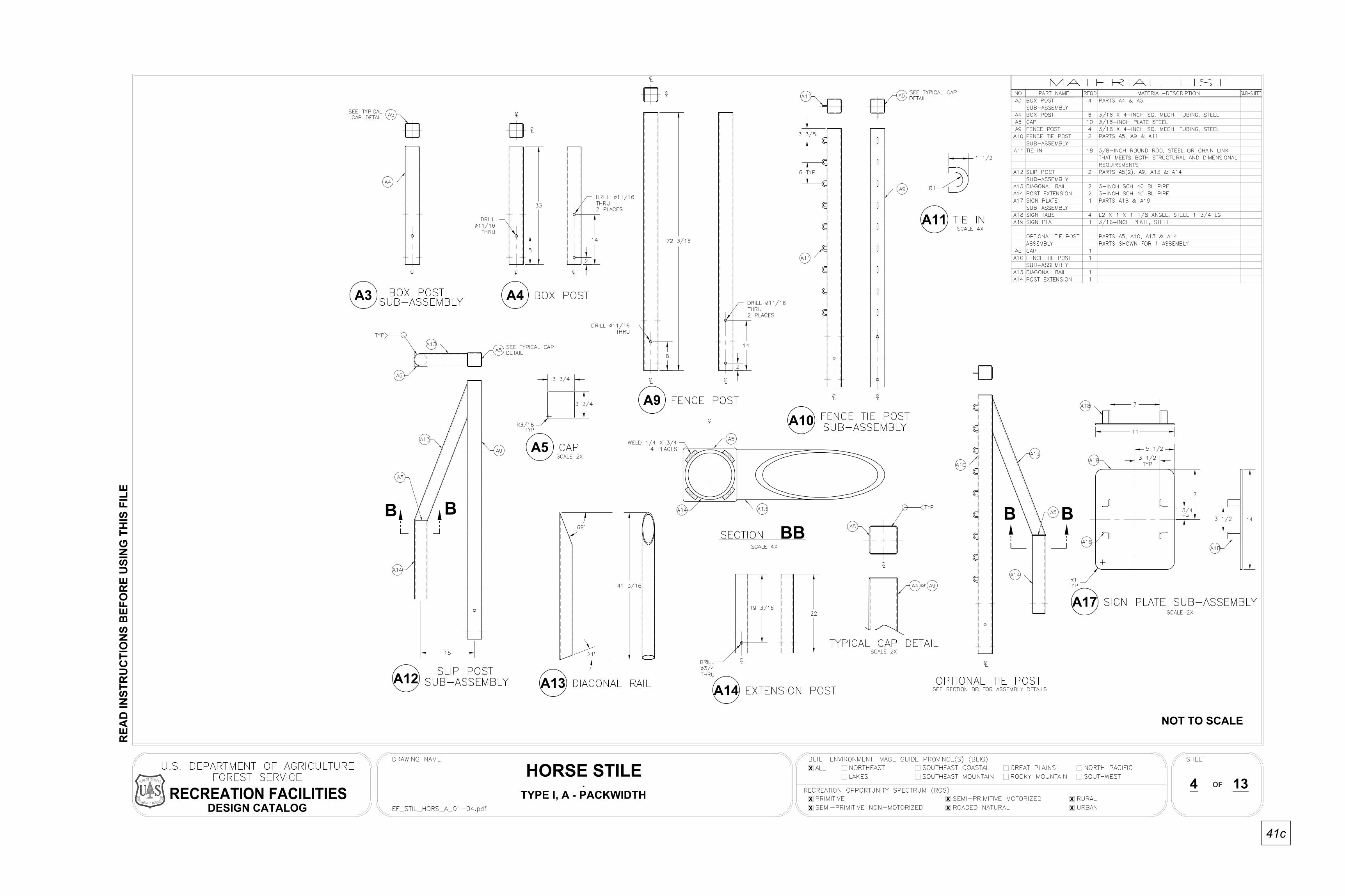
41c
A12
A4
A10
A11
A17
BB
A14A13
BB BB
A5
A3
A9
4HORSE STILE
DESIGN CATALOG
13
NOT TO SCALE
TYPE I, A - PACKWIDTH.
X
XX
XXX
X


41d
B1
A
AA
A
5HORSE STILE
DESIGN CATALOG
13
NOT TO SCALE
TYPE I, B - PACKWIDTH.
X
XX
XXX
X

41e
B10
B2
B8
B9
B7B6
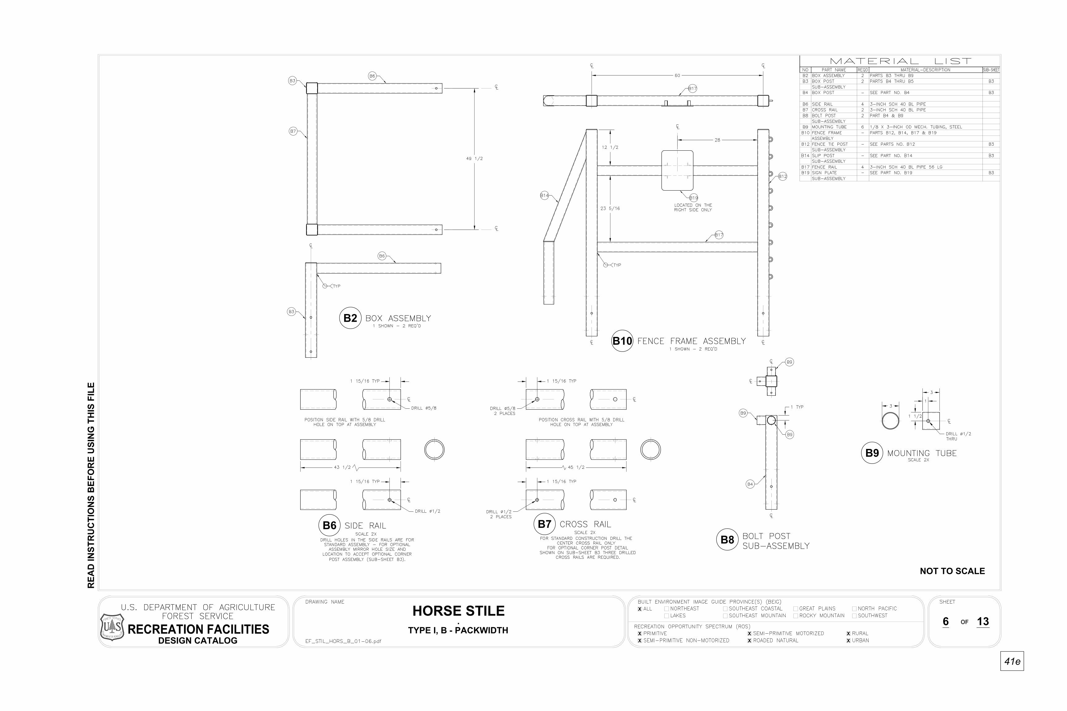
6HORSE STILE
DESIGN CATALOG
13
NOT TO SCALE
TYPE I, B - PACKWIDTH.
X
XX
XXX
X


41f
B14
B12
B13
B19
BB
B16B15
B5
B4B3
B11
BB BB
7HORSE STILE
DESIGN CATALOG
13
NOT TO SCALE
TYPE I, B - PACKWIDTH.
X
XX
XXX
X


41g
C1
A
A
AA
8HORSE STILE
DESIGN CATALOG
13
NOT TO SCALE
TYPE II, C - PACKLESS.
X
XX
XXX
X


41h
C2
C8
9HORSE STILE
DESIGN CATALOG
13
NOT TO SCALE
TYPE II, C - PACKLESS.
X
XX
XXX
X


41i
C12
C10
C11
C16
C5
C14
BB
BB
BB
C4C3
C9
10HORSE STILE
DESIGN CATALOG
13
NOT TO SCALE
TYPE II, C - PACKLESS.
X
XX
XXX
X


41j
D1
A
A
AA
11HORSE STILE
DESIGN CATALOG
13
NOT TO SCALE
TYPE II, D - PACKLESS.
X
XX
XXX
X


41k
D2 D8
D7D6 D9
12HORSE STILE
DESIGN CATALOG
13
NOT TO SCALE
TYPE II, D - PACKLESS.
X
XX
XXX
X


41L
D13
D11
D12
D15
D5
D4
D3
D10
D14
13HORSE STILE
DESIGN CATALOG
13
NOT TO SCALE
TYPE II, D - PACKLESS.
X
XX
XXX
X


43

45


47


49


GUARDRAILS


53

54

55
NO
TC
H T
O F
IT
LOG
, 12'
TO
14'
LO
NG
2'-8"
2"2"
2'-3"
VARIES 2"
2"
BO
LT A
ND
NU
T F
LUS
H W
ITH
TO
P O
F L
OG
WIT
H W
AS
HE
R A
ND
LO
CK
NU
T. R
EC
ES
S3/
4"ÿ
x 24
" G
ALV
. MA
CH
INE
BO
LT
LOG
BA
RR
IER
FR
ON
T E
LEV
AT
ION
8" x
8"
x 32
" R
EIN
FO
RC
ED
CO
NC
RE
TE
PO
ST
SID
E E
LEV
AT
ION
CO
MP
AC
TE
D B
AC
KF
ILL
2" C
LEA
R#3
RE
BA
R
8"
8" T
O 1
2" D
IAM
ET
ER
PE
ELE
D
1 1/
2"
MIN.
2'-0
"
12' O
R 1
4'
8' O
R 1
0'2'
-0"
CH
AM
FE
R

56
CO
MP
AC
TE
D B
AC
KF
ILL
FR
ON
T E
LEV
AT
ION
SA
WE
D T
IMB
ER
GU
AR
D -
RA
IL T
YP
E B
AR
RIE
R
PO
ST
DE
TAIL
)C
ON
CR
ET
E P
OS
T (
SE
E P
RE
CA
ST
CO
NC
RE
TE
)8"
x 8
" x
42"
RE
INF
OR
CE
D
ELE
VA
TIO
NS
IDE
WA
SH
ER
S A
ND
LO
CK
MA
CH
INE
BO
LT W
ITH
7/8"
ÿ x
14"
GA
LV.
NU
T
8"
2'-0
"
12' O
R 1
4'
8' O
R 1
0'
8"3"
2'-0
"
2'-4"
8"
1'-2"
6"
4x8
4x8

57
WE
LD
CO
NC
RE
TE
FO
OT
ER
4" P
IPE
WE
LD
PIP
E R
AIL
1'-6"
4'-6"
5'-0
"5'
-0"
10"
2"


59


61


63

64
NOTES: OPTIONAL 8"-10" POLE. NOTCH POLE 3" TO FIT POST. 1 1/4" 45° CHAMFER ON ENDS. STAIN ALL WOOD MEMBERS TO MATCH DESIGN THEME OR ENVIRONMENT.
FRONT ELEVATION
WOOD RAIL BARRIER
4'
1'-6
"
7' OR 10'
4' OR 7'
COMPACTED
MAX SIZE 1 1/2"
RIGHT ELEVATION
3"1' 6" 0' 1' 2'
SUBGRADE
4"
7"7"
POST
5/8" D X 12" GALVANIZEDMACHINE BOLT WITH NUT,FLAT GALVANIZED WASHERBOTH SIDES. COUNTERSINKFLUSH BOTH SIDES ANDREMOVE AND DEBURR EXCESSLENGTH AFTER INSTALLATION.
FINISH GRADE
4" X 8" ROUGH SAWNDOUGLAS FIR RAIL
3" CRUSHED GRAVEL
1/4" 45° CHAMFER
8 X 8 X 4' PRESSURETREATED DOUGLAS FIR
1'-6"
COMPACTEDSUBGRADE
2"
OPTIONAL ATTACHMENT

65
NO-DIG BARRIERSJeff Applegate, Mendocino National Forest (William Applegate/R5/USDAFS)
The no-dig barrier is a guardrail type barrier that is prefabricated, set into place, and then secured with rebar. The barrier is simple to build and simple to install, and save time and therefore money. Inmate labor has built up to 100 units in a day and has installed up to 120 units in one day. This type barrier is especially good when working around or in archeological sites due to the minimum ground disturbance. There has been very little vandalism or removal of this type barrier. (See figure 29.)
Figure 29.
Materials and ToolsConstruct the no-dig barrier from railroad ties. Purchase the railroad ties in bulk for about $9 each from a lumber yard.
MaterialsStandard railroad ties, #1 or relay gradePressure-treated 8-inch by 8-inch by 8- or 10-foot long Hem-Fir or Douglas-fir posts5/8-inch steel rebar in 20-foot lengths
ToolsChain sawCutting torchHeavy-duty drill (1/2 horsepower)5/8-inch bell-hangers drill bit Sledge hammerStringline Drilling template
Assembly1. Cut the 8-inch by 8-inch pressure-treated
wood (Hem-Fir) into 12-inch lengths using a chain saw. Yield is 8- to 10-support blocks.
2. Cut rebar into 30-inch lengths. Yield is 8 units per 20-foot stick.
3. Use a simple drilling template; set the railroad ties on top of the 8- by 8- by 12-inch blocks, which are placed lengthwise in the template with the outside edge of the block 12 inches from the end of the railroad tie (12.6 inches) on center.
a. The template consists of two plywood squares with a framed “bunk” to hold the 12-inch long lengths of pressure treated Hem-Fir support blocks. Once the blocks are cut to length they are put in the bunks on the two properly spaced templates. A railroad tie is place on top of the two Hem-Fir blocks. The templates allow for a one foot extension of the railroad tie beyond the outside edges of the two Hem-Fir blocks. Once the railroad tie is in the proper position, the tie and the support block are vertically drilled on center with a 5/8-inch diameter bell hangers bit. After drilling, a 30-inch piece of 5/8-inch rebar is pounded down through the hole in the railroad tie and the block, stopping at ground level.

66
4. Drill through the railroad tie and the pressure treated blocks with the 5/8-inch drill bit.
5. Pound a 30-inch stick of rebar through the railroad tie and block with a sledge hammer until flush with the bottom on the block. This will leave about 12 to 14 inches of rebar sticking out of the lumber. (See figure 30.)
Figure 30.
At this point the no-dig barriers are ready to transport on a trailer to the jobsite.
Installation1. Transport the barriers to the jobsite.
2. Use a stringline to lineup the barriers. (This step may not be necessary.)
3. Lineup the barriers with Hem-Fir blocks are in contact with the ground.
4. Use an 8- to 20-pound sledge hammer to pound the 12- to 14-inch length of rebar into the ground until flush with the top of the railroad tie.
5. Simple eyeballing and a little leveling with a McLeod results in a finished product. (See figures 31 and 32.)
Figure 31.
Figure 32.
When in use, if a barrier is backed over or moved out of place by frost heave use a digging bar as a lever to right the barrier. Barriers can be jacked out with a jack and, unless the rebar is badly bent, they can be easily reinstalled.

LARGE
ROCKS


69

70
DEFINITIONSRecreation Opportunity Spectrum (ROS) classificationThe USDA Forest Service uses the Recreation Opportunity Spectrum (ROS) to inventory and classify National Forest System lands. The range of recreational experiences, opportunities, and settings available on a given area of land is classified through the ROS. Classifications include: Primitive, Semiprimitive-Nonmotorized, Semiprimitive-Motorized, Roaded Natural, Rural, and Urban. The USDA Forest Service typically plans and manages for recreational experiences through the application of the ROS. The ROS is a framework for inventorying, planning, and managing the recreational experience and setting.
The public perceives recreation as more than just camping, fishing, and hiking. Research has shown that people choose a specific setting for each of these activities in order to realize a desired set of experiences. For example, hiking on a natural-surfaced trail in a remote setting with few facilities may offer some visitors a sense of solitude, challenge, and self-reliance. In contrast, a hard-surfaced, interpretive, loop trail in an area with facilities and amenities may offer more comfort, security, and social opportunities for other visitors. Maintaining a spectrum of these classes is very important to provide people with choices. See
http://216.239.63.104/search?q=cache:RxHC6ZiIu8YJ:www.fs.fed.us/mntp/plan/
LRMP-D.pdf+recreation+opportunity+spectrum&hl=en.
Built Environment Image Guide (BEIG) The built environment, as used in this publication, refers to the administrative and recreation buildings, landscape structures, site furnishings, structures on roads and trails, and signs installed or operated by the USDA Forest Service, its cooperators, and permittees.
The elements of the built environment constructed on national forest lands and grasslands, or those used for administrative purposes in rural areas, towns, and cities, shall—to the extent practicable—incorporate the principles of sustainability, reflect their place within the natural and cultural landscape, and provide optimal service to our customers and cooperators. These elements will:
• Be located, planned, and designed with respect for the natural systems in which they reside
• Aesthetically integrate their natural, cultural, and experiential context
• Contain design elements, including appropriate signs that reinforce a national agency identity
• Emphasize efficiency of energy and materials consumption in construction and operation
• Serve as premier examples to interpret conservation of natural resources and sustainable development
• Create environments for people to enjoy and gain increased appreciation for the natural environment and in which employees work productively, experiencing the connection to the resources they manage
In so doing, the USDA Forest Service built environment will strengthen and reinforce the image of the agency as an international conservation leader. See
http://fsweb/beig/BEIG_Training/default.htm.
DEFINITIONS
71
WEB SITES
WEB SITES
U.S. Department of Agriculture, Forest Service, Missoula Technology and Development Center. 2003. Sign installation guide.
http://fsweb.mtdc.wo.fs.fed.us/php/library_card.php?p_num=0371%202812.
(Scroll down to Field Implementation, click on ATM Signing.) (26 May 2006).
U.S. Department of Agriculture, Forest Service. 2002. Midewin national tallgrass prairie.
http://www.fs.fed.us/mntp/plan/index.htm. (Scroll down to Prairie Plan, appendixes, D – Recreation Opportunity Spectrum.) (26 May 2006).
U.S. Department of Agriculture, Forest Service. 2005. Sign and poster guidelines for the Forest Service.
http://fsweb.wo.fs.fed.us/eng/roads_trails/signs_os/index.htm.
(See chapter 6 for specifics using the “Road Closed” sign.)
U.S. Department of Agriculture, Forest Service, Northern Regional Office. Access and travel management. http://fsweb.r1.fs.fed.us/e/access_and_travel_
mgmt/atm_index.shtml. (Scroll down to Field Implementation, click on ATM Signing.) (26 May 2006).http://fsweb.wo.fs.fed.us/rhwr/ohv/index.shtml
U.S. Department of Agriculture, Forest Service. 2006. Built environment image guide training. (San Dimas Technology and Development Center.)
http://fsweb/sdtdc.wo.fs.fed.us/programs/rec/beig/BEIG_Training/default.htm.
(26 May 2006).
U.S. Department of Agriculture, Natural Resources Conservation Service. 2006. Delaware standard engineering drawings.
http://www.de.nrcs.usda.gov/technical/technical_references/engineering/eng_
drawings.html. (26 May 2006).
U.S. Department of Transportation, Federal Highway Administration. 2003. Manual on uniform traffic control devices (MUTCD).
http://mutcd.fhwa.dot.gov/. (26 May 2006).
AcknowledgementsSDTDC wishes to thank the following individuals for their review of this publication:
Scott Groenier, civil engineer, USDA Forest Service,
Missoula Technology and Development Center.
Greg Napper, civil engineer, USDA Forest Service,
San Dimas Technology and Development Center.
Don Trammell, USDA Forest Service, Southwest Region,
Trails Unlimited Enterprise Unit.
SDTDC also extends thank yous to all the persons who shared their barrier drawings.
SDTDC’s national publications are available athttp://www.fs.fed.us/eng/pubs.
U.S. Department of Agriculture, Forest Service and U.S. Department of the Interior Bureau of Land Management employees also can view SDTDC’s videos, CDs, and individual project pages on their internal computer networks at:
http://fsweb.sdtdc.wo.fs.fed.us/.

72
TRAIL OHV-WIDTH LIMITER GATE AND NONMOTORIZED TRAIL BARRIERSby Don Trammell, USDA Forest ServiceTrails Unlimited Enterprise Unit
Use these barriers to narrow the width of a trail, thus limiting the type of off-highway vehicle (OHV) allowed on the trail (i.e., keep all-terrain vehicles (ATVs) off motorcycle-only trails) or as a barrier to OHVs on hiking and horse trails.
Trail OHV-width limiter and nonmotorized trail barrier structures can be assembled in several configurations to meet many trail management objectives. Prefabricate the components and then transport them to the installation site for assembly. Depending on the chosen structure, there may be no welding to do in the field. Prefabrication and no field welding are distinct advantages in remote locations.
Consider sight distance (particularly important on higher speed OHV trails) when locating a structure. Install barriers on a level or near level section of trail and provide a turn around area for excluded uses. In addition to making it easier to install the structure, level ground will minimize the impacts of braking and acceleration on the trail segments on each side of the structure. Tie barriers and gates to a fence or a substantial natural feature to prevent people from riding around them. Barriers are less likely to be vandalized in easily viewed locations, such as along side roads.
The left and right halves of the structure are identical in design with the exception of a plate attached to the right half (approach side). Attach a trail-use designation sign to the plate. Use retroreflective, stick-on signs to designate trail use. (See appendix B for sign requirements.)
MaterialsUse 3-inch schedule 40 black iron pipe as a minimum. Corten tubing of similar dimensions also may be used to extend the lifespan of the structure. For either esthetics or in areas of high vandalism, use larger diameter pipe, schedule 80 pipe, or a combination of both. Use continuous welds on all joints and, to prevent a safety hazard, grind down all rough or jagged surfaces. Do not paint the gate; painting creates a long-term maintenance commitment. If the structure is painted, ensure that it contrasts with the background colors of the site so the barrier remains visible.
Use a cross-bar to close the trail to all uses (wet weather, fire danger, and so forth.) (See figure A1.) Slot the interior posts to accommodate a 3-inch by 1/2-inch bar approximately 30 inches above the ground line. Slot the exterior post on one side to accommodate the closure bar when the trail is open. The closure bar must be able to be locked in both the open and closed positions for safety reasons.
Figure A1. This width-limiter gate is closed to all traffic. The sides of the gate are attached to a wire fence.
APPENDIx A

73
Weld loops to the exterior posts (furthest from the trail centerline) and attach a wire fence to prevent users from going around the barrier. Chain links cut in half and welded to the post make excellent loops. Space loops every 4 inches to accommodate various fencing needs. Ensure that these loops do not have square edges so they do not cut the wire.
Anchoring posts makes them more difficult for vandals to remove. Drill 3/4-inch holes through the interior and exterior posts at 3 inches and at 6 inches from the bottom of the posts. The holes should go completely through the posts and be offset 90 degrees from each other. Insert pieces of rebar through holes for post anchors.
Nonmotorized Trail Barrier (Stock) GateThere are four variations that change this gate from a width limiter gate to an OHV barrier. The base structure can be a width-limiter gate or a simple steel rail fence, as shown in the photographs. The variations allow pedestrians and stock to pass over a barrier. Contrast is especially important for visibility if the barrier is used as an OHV barrier and livestock will have to step over the cross-barrier. Place Type 3 object markers or reflective warning tape (red and white stripes) on the structure to warn vehicle users of the barrier’s presence. To promote safe passage, post an informational sign that suggests leading (rather than riding) livestock through the structure.
Variation OneInsert a pipe cross-barrier approximately16 inches above the ground to create a single
horizontal barrier. (An OHV must be lifted over the bar to gain access.) To create this barrier, cut a hole through interior (closest to the trail centerline) posts and insert the next smaller diameter pipe, forming a cross-barrier. This cross-barrier should fit snugly and not be able to be removed once the structure is buried or cemented in the ground. Ensure that the cross-barrier pipe is long enough to span the trail width and still fit securely into the barrier’s side pieces. Done properly, no welding of the cross piece is necessary.
Variation TwoThe second variation adds a U-shaped barrier on both sides of the structure to form a horizontal box. Weld nipples to each side of the interior post parallel to the trail, approximately16 inches above the ground. Each nipple should have an outside diameter sized to fit snugly into the pipe being used for the barrier portion. Fit the whole structure together before the side pieces are buried or cemented in the ground. No welding is necessary if a U-shaped barrier is used on both sides of the structure and the pieces are fitted together properly before being buried or cemented in the ground. If bolts are used to secure the U-shaped barrier pieces to the side pieces for additional strength, vertically insert the bolts to avoid creating a scraping hazard for users.
Construct a U-shaped barrier using a single bent tube for each side with one support leg, or using a welded 3-sided box with 2 support legs. The legs on the U-shaped barrier also should have rebar anchors.
APPENDIx A

74
Variation ThreeThe third variation adds one U-shaped barrier piece along with the cross barrier to crate a shorter box, however, welding is recommended when using this configuration to prevent the structure from being wiggled apart. This addition is to the front of the gate. (See figure A2.)
Figure A2.
Variation FourThe fourth variation adds the cross-barrier piece to the two U-shaped barrier pieces to form three horizontal barriers.
See drawings: Width-Limiter Gate 27 inches, Width-Limiter Gate 30 inches, and Nonmotorized Trail Barrier Gate.
APPENDIx A

75
OBJECT AND BARRIER MARKERS ON OHV ROUTESBy Don Trammell, USDA Forest ServiceTrails Unlimited Enterprise Unit
If the route is a National Forest System (NFS) road, refer to EM-7100-15 Sign and Poster Guidelines for the Forest Service, Chapter 3A, Section 3A.8 – Markings. This section provides all necessary information to properly mark gates or other constructed features that are across, in, or adjacent to roads, and should be followed. (See figures B1 and B2.) Similar guidance for marking objects or barricades within or adjacent to motorized trails is contained in Chapter 5, Section 5.2.2 – Warning Signs and Markers. Mark both sides of all constructed features so they are visible to traffic from both directions. The minimum marking is subject to determination by a recreation study or review.
Figure B1. Striping points down toward the center of the road.
Figure B2. Shows striping on the back side of a double gate.
The following are the suggested minimum markings for constructed features or hazards on motorized NFS trails that intrude into the roadway, trailway, or a combination of both. Constructed features include width limiter gates, cattle guards, and gate posts that are within or immediately adjacent to the trail.
Mark objects with retroreflective yellow and black striped Type 3 object markers or with sheeting applied directly to the object or posts. Type 3 object markers and sheeting come in left and right applications. The stripes should slope down toward the side of the obstruction that traffic is to pass. Whenever possible, install markers approximately 4 feet above the ground. However, if the object is lower than 4 feet, priority should be given to marking the edge of the object closest to the center of the trail regardless of height. A retroreflective area approximately 3-inches wide and 18-inches long is the suggested minimum marking. If
APPENDIx B

76
the closest portion of the object is too low to be effectively marked, a flexible post with retroreflective markers should be installed in line with the obstacle. (See figure B3.)
Figure B3. Wrap the yellow and black sheeting around the pipe pointing to the center of the trail.
If a trail is restricted by a gate or a closure bar, mark the prominent horizontal barrier closest to 4 feet above the ground with retroreflective red and white striped barricade markers or sheeting. At a minimum, two barricade markers, a left-hand and a right-hand marker, should be used on the restriction device with the stripes pointing toward the center of the barrier. The suggested minimum marking area is approximately 3-inches wide by 3-feet long. Mark the horizontal barricades of an off-highway vehicle barrier in the same manner. (See figures B4 and B5.)
Figure B4. Use rectroreflective red and white sheeting to highlight closure bar across trail.
Figure B5. OHV barricade at equestrian gate. (There is no trail in this area.)
Mark gate posts, culvert ends, cattle guard ends, drop offs, and other objects or obstacles located off the trail to warn users a potential hazard. Use retroreflective yellow Type 2 object markers or sheeting. The suggested minimum marking area is approximately 3-inches wide and 6-inches long. (See figure B6.)
Figure B6. Post marked with 6-inch-long yellow sheeting.
APPENDIx B

77
Wherever a restriction device is installed, in addition to the standard barrier and object markings, a sign clarifying the restriction also is recommended. The appropriate access travel management sign should be used. (See EM-7100-15, Chapter 6, Travel Management Signing, at
http://fsweb.wo.fs.fed.us/eng/roads_trails/signs_os/index.htm.
Figures B7 through B11 show the process for applying the sheeting to existing steel structures.
Figure B7. Sand the metal surface to remove rust and prepare a clean and smooth surface.
Figure B8. Clean residue off the surface using a quick drying degreaser/cleaner such as brake parts cleaner. Follow manufacturer’s directions for use.
Figure B9. Measure and cut sheeting to correct size to assure proper fit.
Figure B10. Note, remove backing slowly while pressing sheeting into place to avoid wrinkles.
Figure B11. Apply sheeting to both sides of the barricade.
APPENDIx B


