us navy course navedtra 14028 - aviation electronics technician-basic
TRANSCRIPT
8/14/2019 US Navy Course NAVEDTRA 14028 - Aviation Electronics Technician-Basic
http://slidepdf.com/reader/full/us-navy-course-navedtra-14028-aviation-electronics-technician-basic 1/415
NONRESIDENTTRAINING
COURSE
Aviation Electronics
Technician - Basic
NAVEDTRA 14028
DISTRIBUTION STATEMENT A: Approved for public release; distribution is unlimited.

8/14/2019 US Navy Course NAVEDTRA 14028 - Aviation Electronics Technician-Basic
http://slidepdf.com/reader/full/us-navy-course-navedtra-14028-aviation-electronics-technician-basic 2/415
PREFACE
About this course:
This is a self-study course. By studying this course, you can improve your professional/military knowledge,
as well as prepare for the Navywide advancement-in-rate examination. It contains subject matter about day-to-day occupational knowledge and skill requirements and includes text, tables, and illustrations to help you
understand the information. An additional important feature of this course is its references to useful
information to be found in other publications. The well-prepared Sailor will take the time to look up the
additional information.
History of the course:
• Jun 1991: Original edition released.
• Mar 2003: Minor revision released.
Published by
NAVAL EDUCATION AND TRAINING
PROFESSIONAL DEVELOPMENT
AND TECHNOLOGY CENTER
NAVSUP Logistics Tracking Number
0504-LP-022-3690

8/14/2019 US Navy Course NAVEDTRA 14028 - Aviation Electronics Technician-Basic
http://slidepdf.com/reader/full/us-navy-course-navedtra-14028-aviation-electronics-technician-basic 3/415

8/14/2019 US Navy Course NAVEDTRA 14028 - Aviation Electronics Technician-Basic
http://slidepdf.com/reader/full/us-navy-course-navedtra-14028-aviation-electronics-technician-basic 4/415
TABLE OF CONTENTS
CHAPTER PAGE
1. Physics ................................................................................................................... 1-1
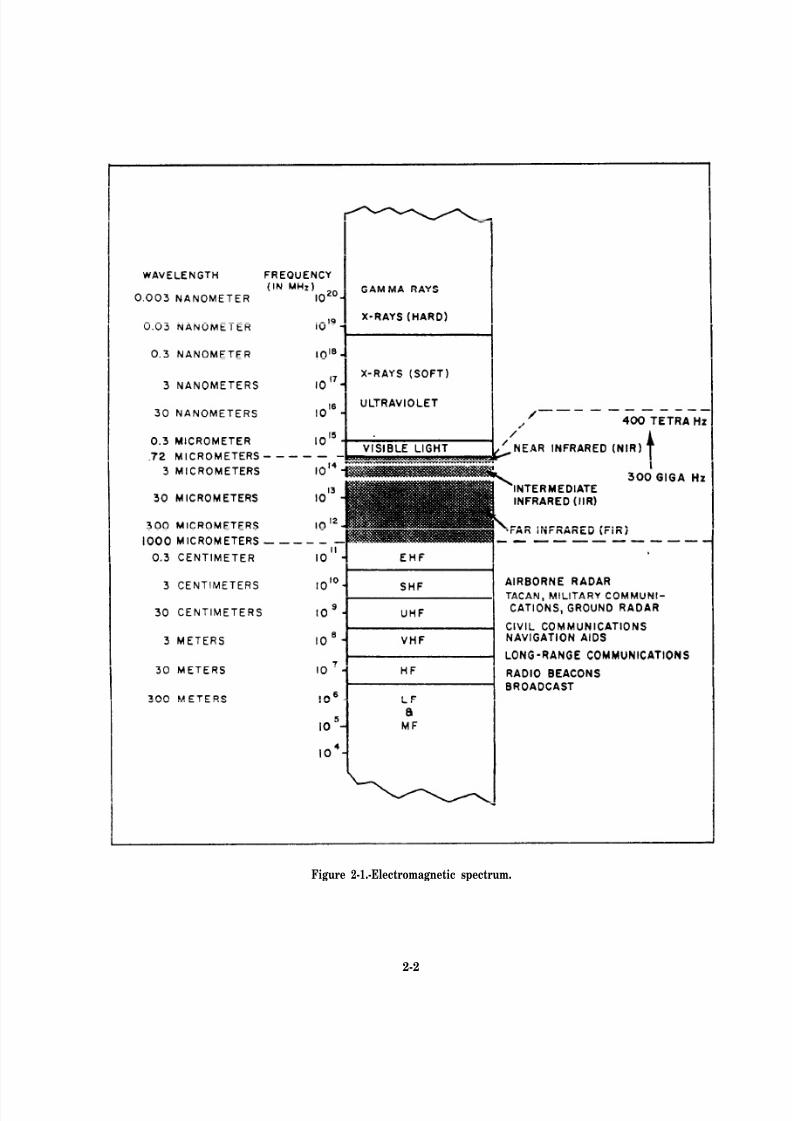
2. Infrared, Lasers, and Fiber Optics.......................................................................... 2-1
3. Analog Fundamentals............................................................................................. 3-1
4. Digital Computers .................................................................................................. 4-1
This chapter has been deleted. For information on number systems, logic, and
digital computers, refer to Nonresident Training Course (NRTC) Navy
Electricity and Electronics Training Series (NEETS), Module 13,
NAVEDTRA 14185, and Module 22, NAVEDTRA 14194.
5. Aviation Systems Fundamentals and Support Equipment ..................................... 5-1
6. Avionics Maintenance............................................................................................ 6-1
7. Avionic Drawings, Schematics, Handtools, and Materials.................................... 7-1
8. Test Equipment ...................................................................................................... 8-1
9. Safety and Security ................................................................................................ 9-1
APPENDIX
I. Glossary ................................................................................................................. AI-1
II. Symbols, Formulas, and Measurements................................................................. AII-1

8/14/2019 US Navy Course NAVEDTRA 14028 - Aviation Electronics Technician-Basic
http://slidepdf.com/reader/full/us-navy-course-navedtra-14028-aviation-electronics-technician-basic 5/415
8/14/2019 US Navy Course NAVEDTRA 14028 - Aviation Electronics Technician-Basic
http://slidepdf.com/reader/full/us-navy-course-navedtra-14028-aviation-electronics-technician-basic 6/415
8/14/2019 US Navy Course NAVEDTRA 14028 - Aviation Electronics Technician-Basic
http://slidepdf.com/reader/full/us-navy-course-navedtra-14028-aviation-electronics-technician-basic 7/415
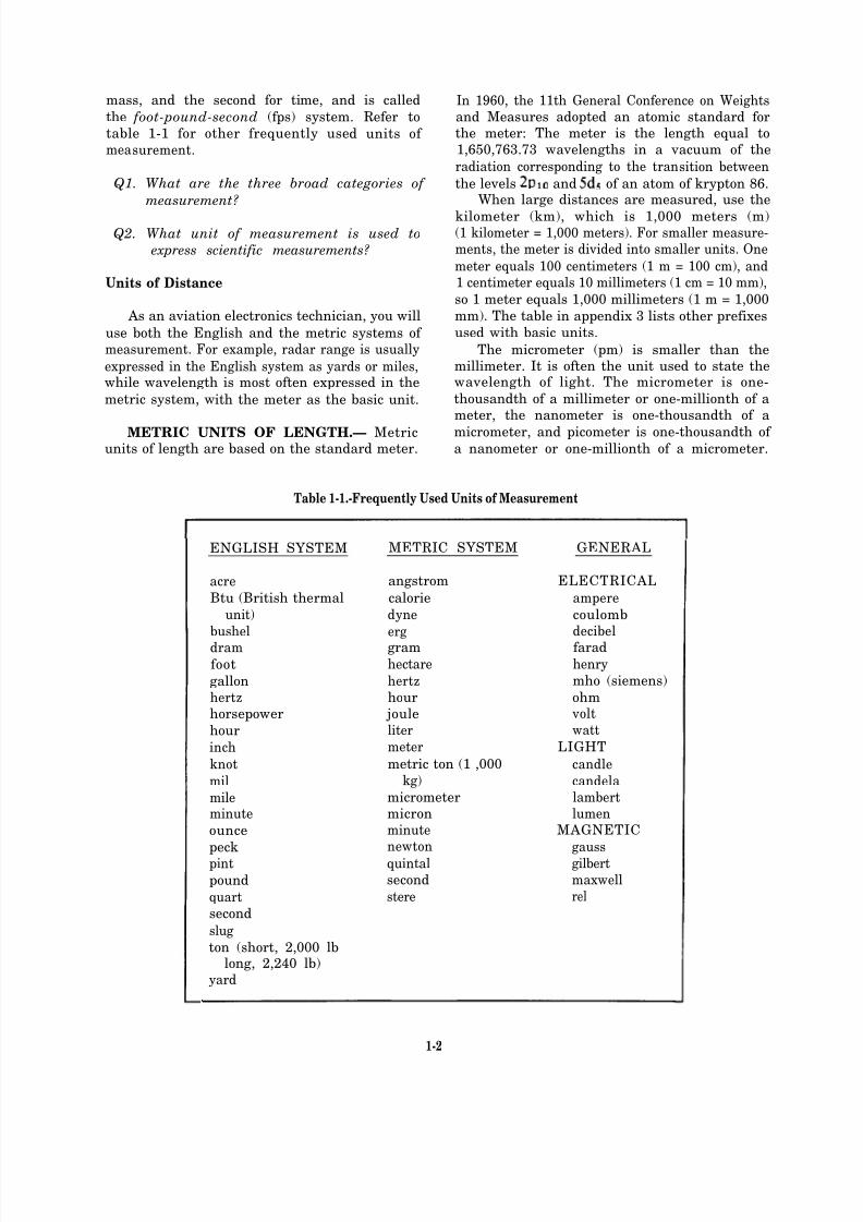
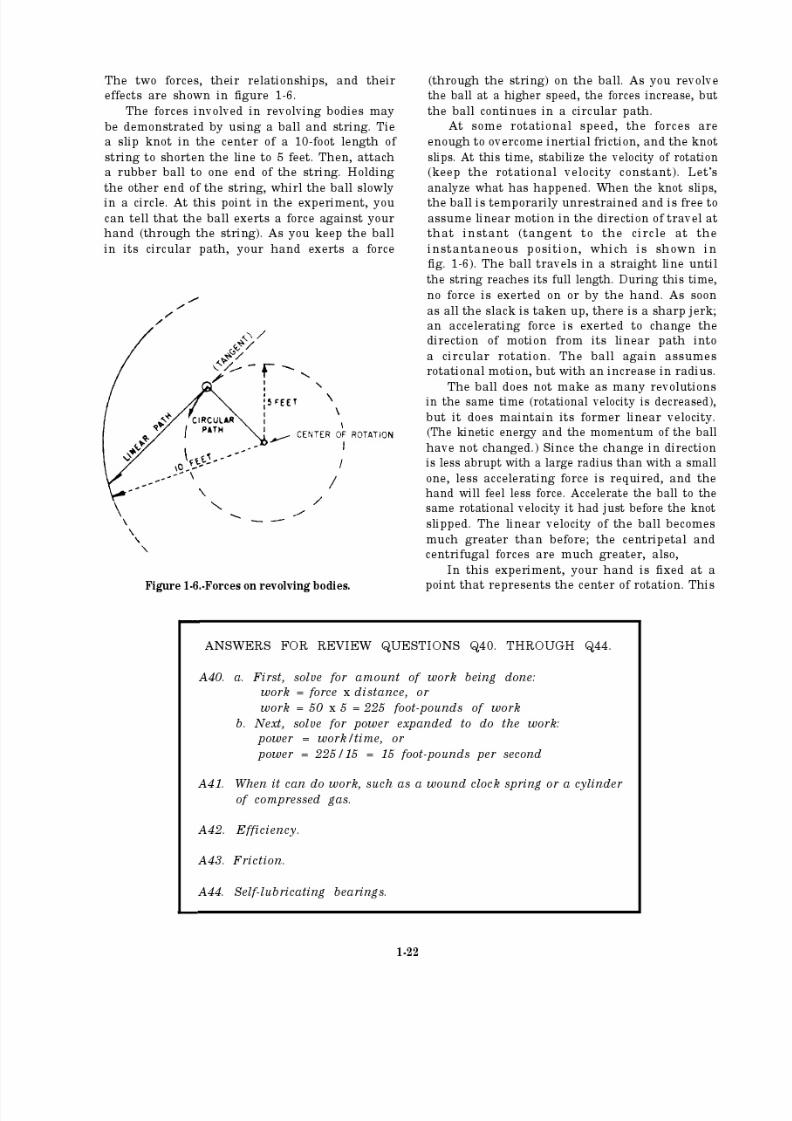
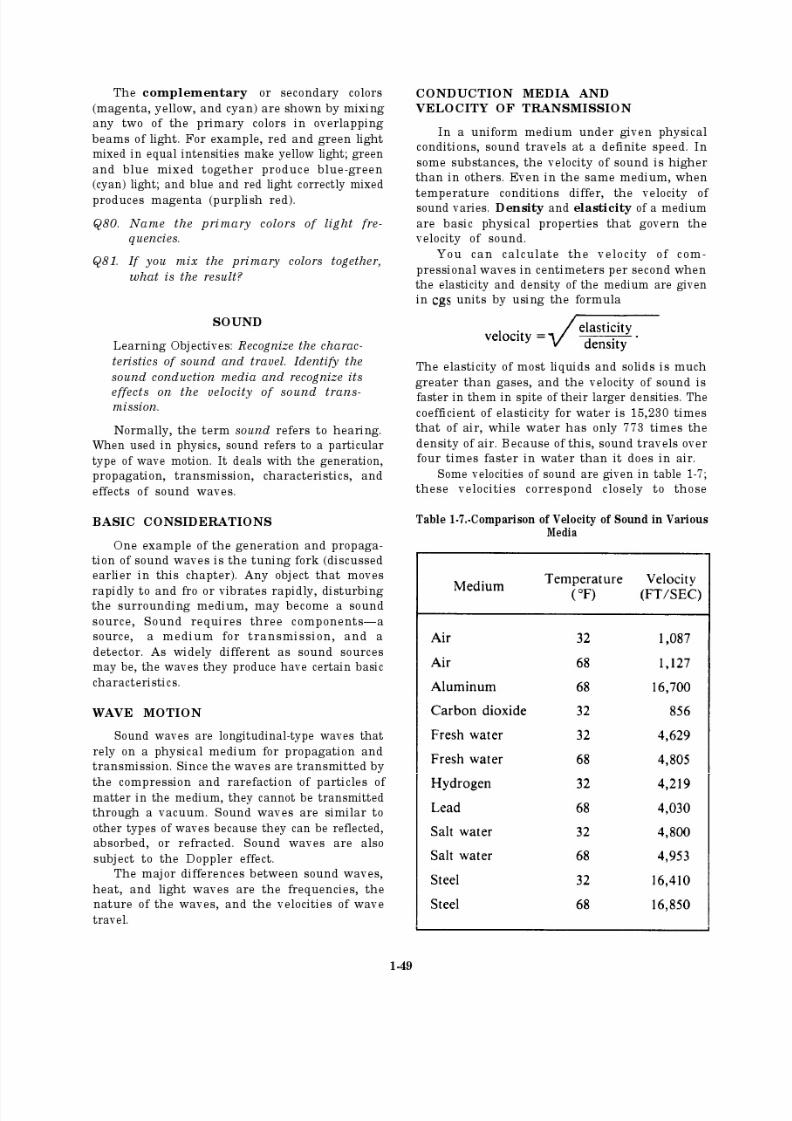
mass, and the second for time, and is called
the foot-pound-second (fps) system. Refer to
table 1-1 for other frequently used units of measurement.
Q1. What are the three broad categories of
measurement?
Q2. What unit of measurement is used to
express scientific measurements?
Units of Distance
As an aviation electronics technician, you will
use both the English and the metric systems of measurement. For example, radar range is usually
expressed in the English system as yards or miles,while wavelength is most often expressed in the
metric system, with the meter as the basic unit.
METRIC UNITS OF LENGTH.— Metricunits of length are based on the standard meter.
In 1960, the 11th General Conference on Weightsand Measures adopted an atomic standard forthe meter: The meter is the length equal to1,650,763.73 wavelengths in a vacuum of the
radiation corresponding to the transition between
the levels and of an atom of krypton 86.When large distances are measured, use the
kilometer (km), which is 1,000 meters (m)(1 kilometer = 1,000 meters). For smaller measure-ments, the meter is divided into smaller units. One
meter equals 100 centimeters (1 m = 100 cm), and1 centimeter equals 10 millimeters (1 cm = 10 mm),
so 1 meter equals 1,000 millimeters (1 m = 1,000
mm). The table in appendix 3 lists other prefixes
used with basic units.
The micrometer (pm) is smaller than themillimeter. It is often the unit used to state thewavelength of light. The micrometer is one-
thousandth of a millimeter or one-millionth of ameter, the nanometer is one-thousandth of a
micrometer, and picometer is one-thousandth of a nanometer or one-millionth of a micrometer.
Table 1-1.-Frequently Used Units of Measurement
ENGLISH SYSTEM METRIC SYSTEM GENERAL
acre angstrom ELECTRICAL
Btu (British thermal calorie ampere
unit) dyne coulomb
bushel erg decibel
dram gram faradfoot hectare henry
gallon hertz mho (siemens)
hertz hour ohmhorsepower joule volt
hour liter watt
inch meter LIGHT
knot metric ton (1 ,000 candle
mil kg) candela
mile micrometer lambertminute micron lumen
ounce minute MAGNETIC
peck newton gauss
pint quintal gilbert
pound second maxwell
quart stere rel
second
slug
ton (short, 2,000 lblong, 2,240 lb)
yard
1-2

8/14/2019 US Navy Course NAVEDTRA 14028 - Aviation Electronics Technician-Basic
http://slidepdf.com/reader/full/us-navy-course-navedtra-14028-aviation-electronics-technician-basic 8/415
8/14/2019 US Navy Course NAVEDTRA 14028 - Aviation Electronics Technician-Basic
http://slidepdf.com/reader/full/us-navy-course-navedtra-14028-aviation-electronics-technician-basic 9/415

8/14/2019 US Navy Course NAVEDTRA 14028 - Aviation Electronics Technician-Basic
http://slidepdf.com/reader/full/us-navy-course-navedtra-14028-aviation-electronics-technician-basic 10/415
8/14/2019 US Navy Course NAVEDTRA 14028 - Aviation Electronics Technician-Basic
http://slidepdf.com/reader/full/us-navy-course-navedtra-14028-aviation-electronics-technician-basic 11/415
8/14/2019 US Navy Course NAVEDTRA 14028 - Aviation Electronics Technician-Basic
http://slidepdf.com/reader/full/us-navy-course-navedtra-14028-aviation-electronics-technician-basic 12/415
8/14/2019 US Navy Course NAVEDTRA 14028 - Aviation Electronics Technician-Basic
http://slidepdf.com/reader/full/us-navy-course-navedtra-14028-aviation-electronics-technician-basic 13/415
ocean than it weighs at sea level, and it weighs
more a mile below sea level.
Q11.
Q12.
Q13.
Q14.
Q15.
Q16.
What relationship is defined by the
equation mc2?
Name the concept of the statement “Two
objects can’t occupy the same space at thesame time.”
What action must be applied to an object
to overcome inertia?
What is meant by the term acceleration?
Why is force considered a vector quantity?
In the English system of measurement, what
force is expressed in pounds?
Density and Specific Gravity
The density of a substance is its weight per unit volume. A cubic foot of water weighs 62.4
pounds; the density of water is 62.4 pounds per
cubic foot. (In the metric system, the density of water is 1 gram per cubic centimeter.)
The specific gravity (sp gr) of a substance is
the ratio of the density of the substance to thedensity of water and is expressed by the equation
weight of substancespecific gravity =
weight of equal volume of water.
Specific gravity is not expressed in units of measurement, but as a pure number. For example,
if a substance has a specific gravity of 4, 1 cubic
foot of the substance weighs 4 times as much as
a cubic foot of water, 62.4 times 4 = 249.6pounds. In metric units, 1 cubic centimeter of a
substance with a specific gravity of 4 weighs 1
times 4, or 4 grams. (Note that in the metricsystem of units, the specific gravity of a substance
has the same numerical value as its density.)Specific gravity and density are independent
of the size of the sample under consideration and
depend only upon the substance of the sample.
See table 1-4 for typical values of specific gravityfor various substances.
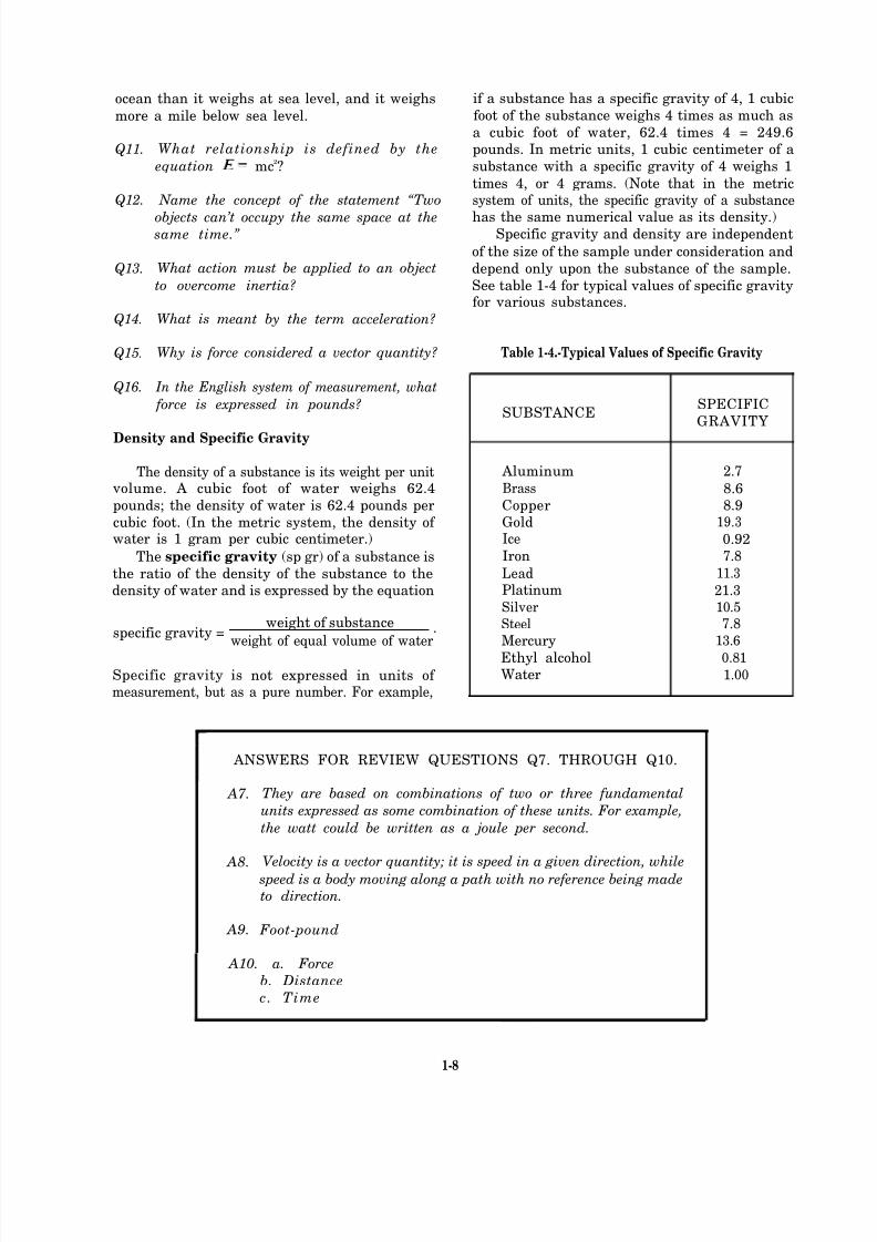
Table 1-4.-Typical Values of Specific Gravity
SUBSTANCESPECIFIC
GRAVITY
Aluminum 2.7
Brass 8.6Copper 8.9Gold 19.3
Ice 0.92Iron 7.8
Lead 11.3
Platinum 21.3Silver 10.5
Steel 7.8
Mercury 13.6
Ethyl alcohol 0.81Water 1.00
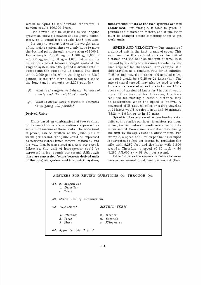
ANSWERS FOR REVIEW QUESTIONS Q7. THROUGH Q10.
A7.
A8.
A9.
They are based on combinations of two or three fundamental
units expressed as some combination of these units. For example,
the watt could be written as a joule per second.
Velocity is a vector quantity; it is speed in a given direction, while
speed is a body moving along a path with no reference being made
to direction.
Foot-pound
A10. a. Force
b. Distance
c. Time
1-8
8/14/2019 US Navy Course NAVEDTRA 14028 - Aviation Electronics Technician-Basic
http://slidepdf.com/reader/full/us-navy-course-navedtra-14028-aviation-electronics-technician-basic 14/415
8/14/2019 US Navy Course NAVEDTRA 14028 - Aviation Electronics Technician-Basic
http://slidepdf.com/reader/full/us-navy-course-navedtra-14028-aviation-electronics-technician-basic 15/415

8/14/2019 US Navy Course NAVEDTRA 14028 - Aviation Electronics Technician-Basic
http://slidepdf.com/reader/full/us-navy-course-navedtra-14028-aviation-electronics-technician-basic 16/415
8/14/2019 US Navy Course NAVEDTRA 14028 - Aviation Electronics Technician-Basic
http://slidepdf.com/reader/full/us-navy-course-navedtra-14028-aviation-electronics-technician-basic 17/415
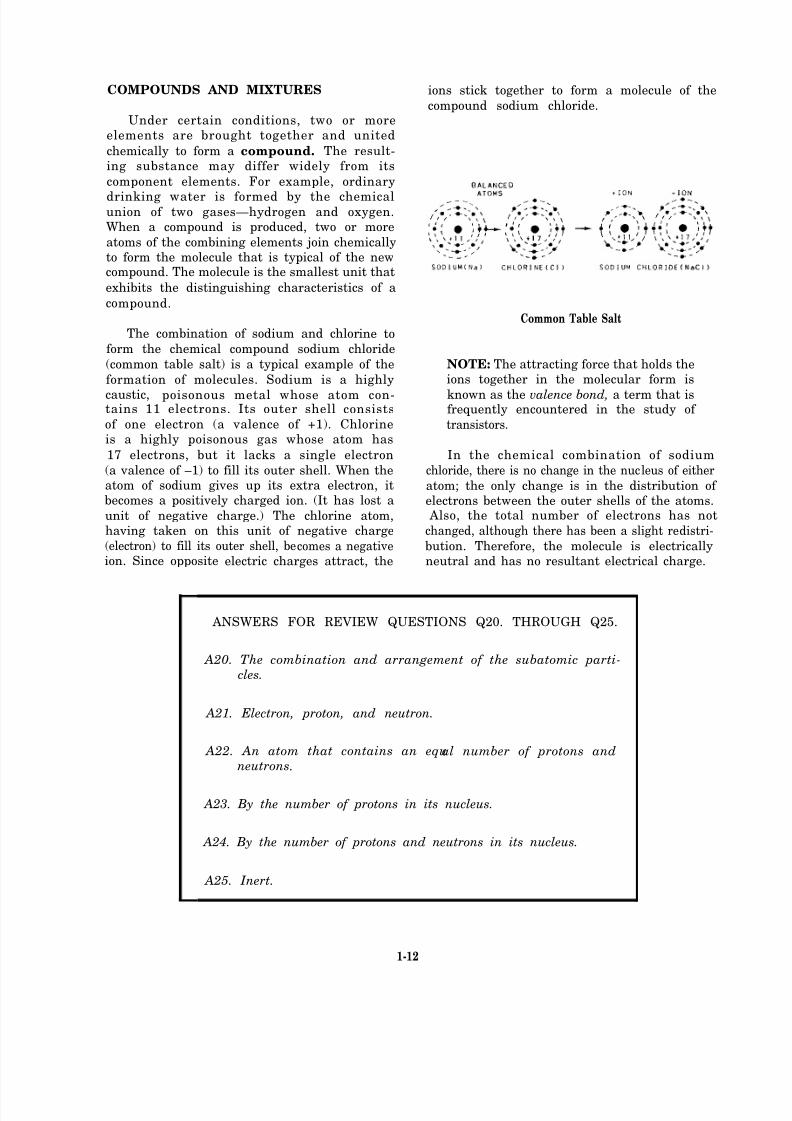
COMPOUNDS AND MIXTURES ions stick together to form a molecule of the
compound sodium chloride.Under certain conditions, two or more
elements are brought together and united
chemically to form a compound. The result-ing substance may differ widely from its
component elements. For example, ordinary
drinking water is formed by the chemicalunion of two gases—hydrogen and oxygen.When a compound is produced, two or more
atoms of the combining elements join chemicallyto form the molecule that is typical of the newcompound. The molecule is the smallest unit that
exhibits the distinguishing characteristics of a
compound.
The combination of sodium and chlorine to
form the chemical compound sodium chloride
(common table salt) is a typical example of the
formation of molecules. Sodium is a highly
caustic, poisonous metal whose atom con-tains 11 electrons. Its outer shell consists
of one electron (a valence of +1). Chlorineis a highly poisonous gas whose atom has
17 electrons, but it lacks a single electron
(a valence of –1) to fill its outer shell. When theatom of sodium gives up its extra electron, itbecomes a positively charged ion. (It has lost a
unit of negative charge.) The chlorine atom,having taken on this unit of negative charge
(electron) to fill its outer shell, becomes a negativeion. Since opposite electric charges attract, the
Common Table Salt
NOTE: The attracting force that holds theions together in the molecular form is
known as the valence bond, a term that isfrequently encountered in the study of
transistors.
In the chemical combination of sodium
chloride, there is no change in the nucleus of either
atom; the only change is in the distribution of electrons between the outer shells of the atoms. Also, the total number of electrons has not
changed, although there has been a slight redistri-
bution. Therefore, the molecule is electricallyneutral and has no resultant electrical charge.
ANSWERS FOR REVIEW QUESTIONS Q20. THROUGH Q25.
A20. The combination and arrangement of the subatomic parti-cles.
A21. Electron, proton, and neutron.
A22. An atom that contains an equal number of protons andneutrons.
A23. By the number of protons in its nucleus.
A24. By the number of protons and neutrons in its nucleus.
A25. Inert.
1-12
8/14/2019 US Navy Course NAVEDTRA 14028 - Aviation Electronics Technician-Basic
http://slidepdf.com/reader/full/us-navy-course-navedtra-14028-aviation-electronics-technician-basic 18/415

8/14/2019 US Navy Course NAVEDTRA 14028 - Aviation Electronics Technician-Basic
http://slidepdf.com/reader/full/us-navy-course-navedtra-14028-aviation-electronics-technician-basic 19/415

8/14/2019 US Navy Course NAVEDTRA 14028 - Aviation Electronics Technician-Basic
http://slidepdf.com/reader/full/us-navy-course-navedtra-14028-aviation-electronics-technician-basic 20/415
8/14/2019 US Navy Course NAVEDTRA 14028 - Aviation Electronics Technician-Basic
http://slidepdf.com/reader/full/us-navy-course-navedtra-14028-aviation-electronics-technician-basic 21/415
8/14/2019 US Navy Course NAVEDTRA 14028 - Aviation Electronics Technician-Basic
http://slidepdf.com/reader/full/us-navy-course-navedtra-14028-aviation-electronics-technician-basic 22/415
8/14/2019 US Navy Course NAVEDTRA 14028 - Aviation Electronics Technician-Basic
http://slidepdf.com/reader/full/us-navy-course-navedtra-14028-aviation-electronics-technician-basic 23/415
needed to give a 1-ton car an acceleration of
In the metric system, the newton is the forcethat causes a mass of 1 kg to be accelerated
Since g = a 1-kg mass exerts
a force of 9.8 newtons due to gravity. A newton
is equal to 0.224 lb.
The dyne is the force that causes a mass of 1 g to be accelerated Therefore, a mass
of 1 g exerts a force of 980 dynes due to gravity.
An accelerating force applied to the center of gravity to accelerate a body with no rotation iscalled a translational force. The force applied to
cause a body to rotate about a point is called atorque force,
Laws of Motion
Among the most important discoveries intheoretical physics are the three fundamental laws
ANSWERS FOR REVIEW QUESTIONS Q28. THROUGH Q38.
A28. a. Solid
b. Liquid
c. Gas
A29. a. Cohesion and adhesion
b. Tensile strengthc. Ductilityd. Malleability
e. Hardness
f. Brittleness
g. Elasticity
A30. a. Component parts of a system can be placed at separated
points
b. Hydraulic energy is transmitted around corners without gears
and levers
A31. To study the kinetic theory of gases.
A32. a. 0 Kelvin
b. -273° Celsius
A33. Boyle.
A34. “All gases expand and contract in direct proportion to the changein the absolute temperature, pro vialed the pressure is held
constant.”
A35. M echanics.
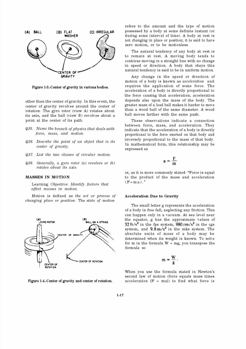
A36. The point where a single force, equal to the gravitational forceand directed up, sustains the body at rest.
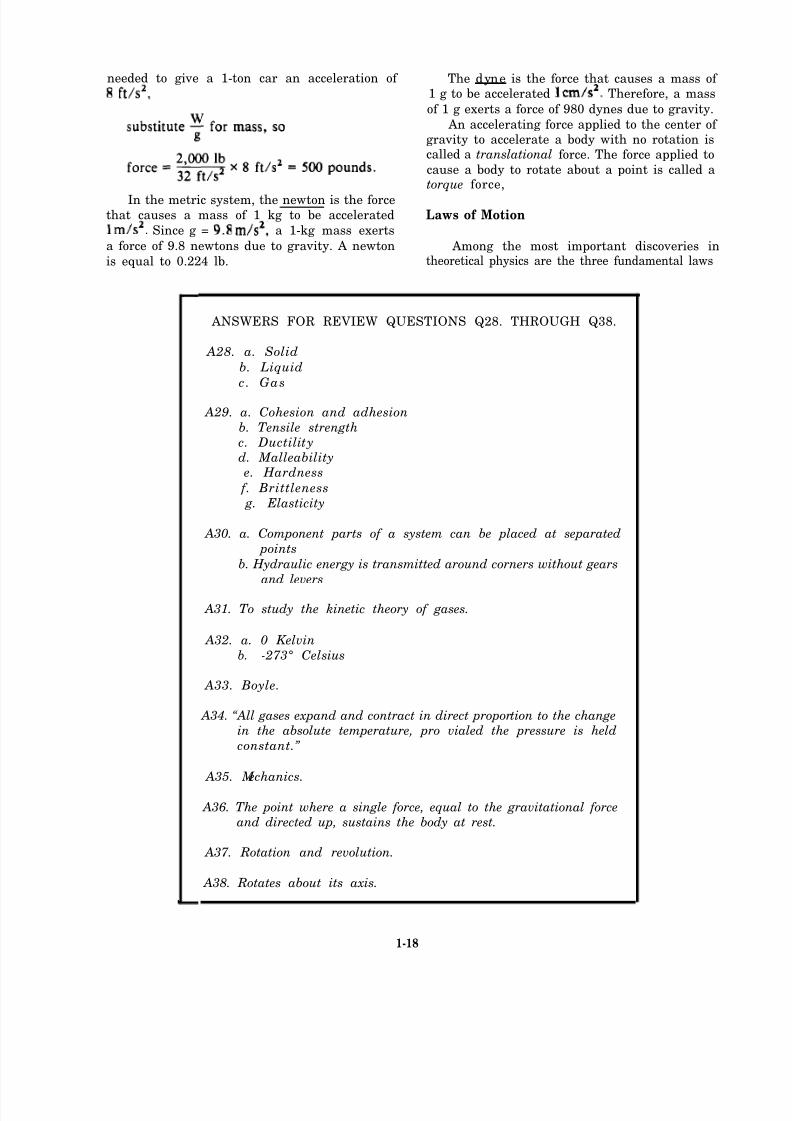
A37. Rotation and revolution.
A38. Rotates about its axis.
1-18

8/14/2019 US Navy Course NAVEDTRA 14028 - Aviation Electronics Technician-Basic
http://slidepdf.com/reader/full/us-navy-course-navedtra-14028-aviation-electronics-technician-basic 24/415
8/14/2019 US Navy Course NAVEDTRA 14028 - Aviation Electronics Technician-Basic
http://slidepdf.com/reader/full/us-navy-course-navedtra-14028-aviation-electronics-technician-basic 25/415
8/14/2019 US Navy Course NAVEDTRA 14028 - Aviation Electronics Technician-Basic
http://slidepdf.com/reader/full/us-navy-course-navedtra-14028-aviation-electronics-technician-basic 26/415
8/14/2019 US Navy Course NAVEDTRA 14028 - Aviation Electronics Technician-Basic
http://slidepdf.com/reader/full/us-navy-course-navedtra-14028-aviation-electronics-technician-basic 27/415
8/14/2019 US Navy Course NAVEDTRA 14028 - Aviation Electronics Technician-Basic
http://slidepdf.com/reader/full/us-navy-course-navedtra-14028-aviation-electronics-technician-basic 28/415
8/14/2019 US Navy Course NAVEDTRA 14028 - Aviation Electronics Technician-Basic
http://slidepdf.com/reader/full/us-navy-course-navedtra-14028-aviation-electronics-technician-basic 29/415
8/14/2019 US Navy Course NAVEDTRA 14028 - Aviation Electronics Technician-Basic
http://slidepdf.com/reader/full/us-navy-course-navedtra-14028-aviation-electronics-technician-basic 30/415
8/14/2019 US Navy Course NAVEDTRA 14028 - Aviation Electronics Technician-Basic
http://slidepdf.com/reader/full/us-navy-course-navedtra-14028-aviation-electronics-technician-basic 31/415
8/14/2019 US Navy Course NAVEDTRA 14028 - Aviation Electronics Technician-Basic
http://slidepdf.com/reader/full/us-navy-course-navedtra-14028-aviation-electronics-technician-basic 32/415
8/14/2019 US Navy Course NAVEDTRA 14028 - Aviation Electronics Technician-Basic
http://slidepdf.com/reader/full/us-navy-course-navedtra-14028-aviation-electronics-technician-basic 33/415

8/14/2019 US Navy Course NAVEDTRA 14028 - Aviation Electronics Technician-Basic
http://slidepdf.com/reader/full/us-navy-course-navedtra-14028-aviation-electronics-technician-basic 34/415
DIFFRACTION
Dif fraction (fig. 1-11.) is the bending of thepath of waves when the wavefront is limited by an
obstruction. This is very easy to observe in water
waves. Generally, the lower frequency waves
diffract more than those at higher frequency. You
can hear the diffraction insound waves bylistening to music from an outdoor source. Then,
step behind a solid obstruction, such as a brickwall. The high notes, having less diffraction, seem
reduced in loudness more than the low notes.
Broadcast band radio waves often travel over tothe opposite side of a mountain from their sourcebecause of diffraction. Higher frequency TV
signals from the same city might not be detected
on the opposite side of the same mountain.
DOPPLER EFFECT
When there is relative motion between the
source of a wave and a detector of that wave, the
Figure 1-11.-Diffraction.
1-29
8/14/2019 US Navy Course NAVEDTRA 14028 - Aviation Electronics Technician-Basic
http://slidepdf.com/reader/full/us-navy-course-navedtra-14028-aviation-electronics-technician-basic 35/415
8/14/2019 US Navy Course NAVEDTRA 14028 - Aviation Electronics Technician-Basic
http://slidepdf.com/reader/full/us-navy-course-navedtra-14028-aviation-electronics-technician-basic 36/415

8/14/2019 US Navy Course NAVEDTRA 14028 - Aviation Electronics Technician-Basic
http://slidepdf.com/reader/full/us-navy-course-navedtra-14028-aviation-electronics-technician-basic 37/415
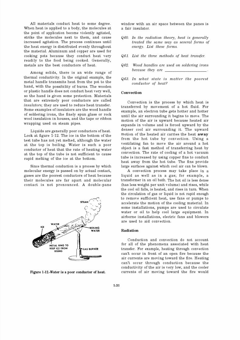
overcome the transfer of heat outward. Therefore,heat must travel across space by some means other
than conduction and convection.
Conduction and convection take place onlythrough molecular contact within some medium;
therefore, heat from the sun reaches the earth by
some other method. (Outer space is an almostperfect vacuum.) The third method of heattransfer is known as radiation.
The term radiation refers to the continual
emission of energy from the surface of all bodies.This energy is known as radiant energy. Radiant
energy is in the form of electromagnetic waves andis identical in nature to light waves, radio waves,and X-rays, except for a difference in wavelength.
Sunlight is radiant heat energy that travels a great
distance through space to reach the earth. These
electromagnetic heat waves are absorbed when
they come in contact with nontransparent bodies.The motion of the molecules in the body increases,
as indicated by an increase in the temperature of the body.
The differences between conduction, con- vection, and radiation are discussed below,
Conduction and convection are extremelyslow, while radiation takes place with the speedof light. You can see this at the time of an eclipseof the sun when heat from the sun is shut off at
the same time as light is shut out.
Radiant heat may pass through a mediumwithout heating it. For example, the air inside a
greenhouse may be much warmer than the glass
through which the sun’s rays pass.
Conducted or convected heat may travelin roundabout routes, while radiant heat alwaystravels in a straight line. For example, radiation
is cut off when a screen is placed between the
source of heat and the body to be protected.
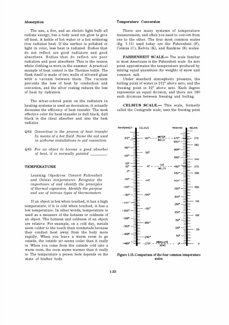
ANSWERS FOR REVIEW QUESTIONS Q56. THROUGH Q63.
A56. As a wave travels through one medium it is traveling at a specificvelocity of propagation. When it reaches a new medium, the
velocity of propagation changes. If the ray is not perpendicular
to the boundary between the two media, the ray will change
direction and bend. This is known as refraction.
A57. a. The angle of incidence
b. The index of refraction
A58. Diffraction occurs when the path of waves is bent because of
an obstruction.
A59. The relative motion between the source of a wave and a detectorof that wave. The frequency of the wave at the detector position
differs from the frequency of the wave at the source.
A60. a. Radio waves
b. Heatc. Light
A61. a. Conduction
b. Convectionc. Radiation
A62. Poor conductors of heat
A63. Gas
1-32
8/14/2019 US Navy Course NAVEDTRA 14028 - Aviation Electronics Technician-Basic
http://slidepdf.com/reader/full/us-navy-course-navedtra-14028-aviation-electronics-technician-basic 38/415
8/14/2019 US Navy Course NAVEDTRA 14028 - Aviation Electronics Technician-Basic
http://slidepdf.com/reader/full/us-navy-course-navedtra-14028-aviation-electronics-technician-basic 39/415
8/14/2019 US Navy Course NAVEDTRA 14028 - Aviation Electronics Technician-Basic
http://slidepdf.com/reader/full/us-navy-course-navedtra-14028-aviation-electronics-technician-basic 40/415

8/14/2019 US Navy Course NAVEDTRA 14028 - Aviation Electronics Technician-Basic
http://slidepdf.com/reader/full/us-navy-course-navedtra-14028-aviation-electronics-technician-basic 41/415
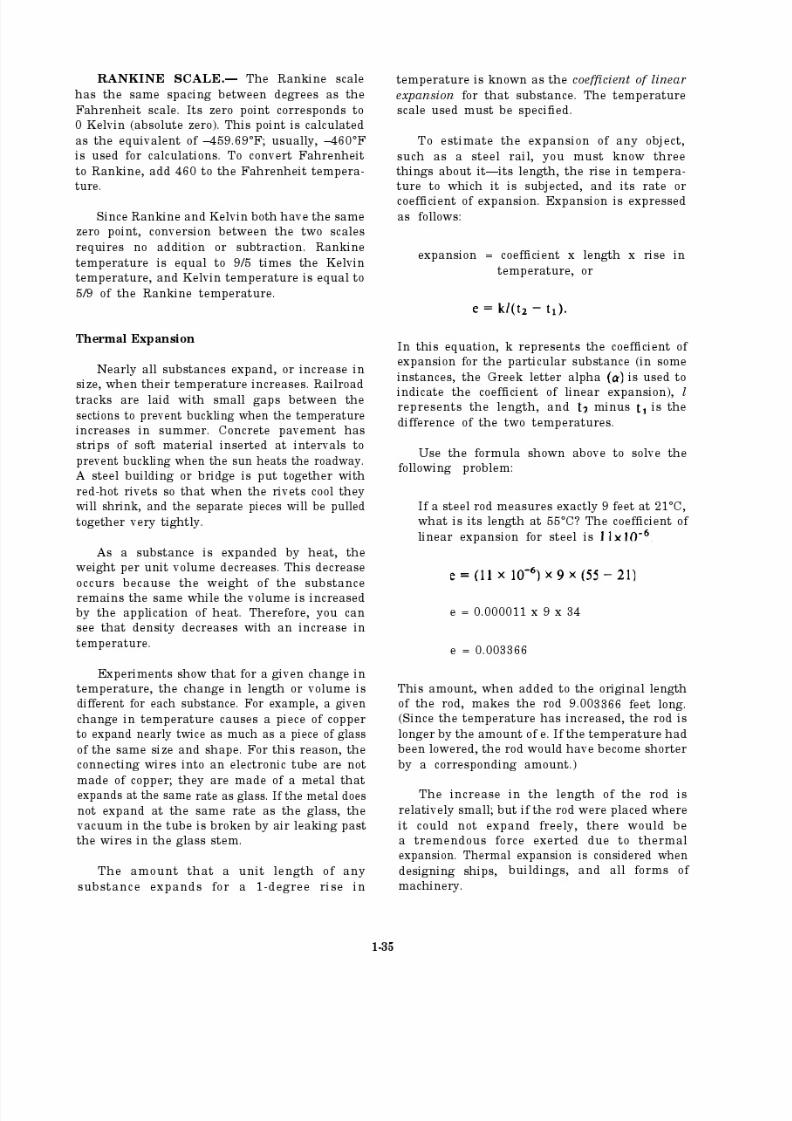
Table 1-5.-Linear Expansion Coefficients
SUBSTANCECOEFFICIENT OF
LINEAR E XPANSION
Aluminum 24 x
Brass 19 x
Copper 17 x
Glass 4 to 9 x
Kovar 4 to 9 x
Lead 28 x
Iron, Steel 11 x
Quartz 0.4 x
Zinc 26 x
Figure 1-15.-Thermostat.
Refer to table 1-5 for a list of the coefficients
of linear expansion (approximate values) of some
substances per °C. A practical application for the difference in
the coefficients of linear expansion is thethermostat. This instrument is made of two strips
of different metals fastened together. When thetemperature changes, the strip bends because of the unequal expansion of the metals (fig. 1-14).
Thermostats (fig. 1-15) are used in overload relays
for motors, in temperature-sensitive switches, andin electric ovens.
The coefficient of surface or area expansionis approximately twice the coefficient of linear
expansion. The coefficient of volume expansion
is approximately three times the coefficient of linear expansion. It is an interesting fact that in
a plate containing a hole, the area of the hole
Figure 1-14.-Compound bar.
expands at the same rate as the surroundingmaterial. In the case of a volume of air enclosed
by a thin solid wall, the volume of air expandsat the same rate as that of a solid body made of the same material as the walls.
Thermometers
The measurement of temperature is known asthermometry. Many modern thermometers use
liquids in sealed containers. The best liquids touse in the construction of thermometers arealcohol and mercury because they have low
freezing points.
LIQUID THERMOMETERS.— The commonlaboratory thermometer is constructed so it
indicates a change of 10 in temperature. A bulb
is blown at one end of a piece of glass tubinghaving a small bore. Then, the tube and bulb arefilled with a liquid. During this process, the
temperature of both the liquid and the tube arekept at a point higher than the thermometer willreach in normal usage. The glass tube is sealed,
and the thermometer is allowed to cool. During
the cooling process, the liquid falls away from the
top of the tube and creates a vacuum in the
thermometer. The thermometer is marked byplacing it in melting ice, The height of the cooledliquid column is marked as the 0°C point.
1-36

8/14/2019 US Navy Course NAVEDTRA 14028 - Aviation Electronics Technician-Basic
http://slidepdf.com/reader/full/us-navy-course-navedtra-14028-aviation-electronics-technician-basic 42/415

8/14/2019 US Navy Course NAVEDTRA 14028 - Aviation Electronics Technician-Basic
http://slidepdf.com/reader/full/us-navy-course-navedtra-14028-aviation-electronics-technician-basic 43/415
8/14/2019 US Navy Course NAVEDTRA 14028 - Aviation Electronics Technician-Basic
http://slidepdf.com/reader/full/us-navy-course-navedtra-14028-aviation-electronics-technician-basic 44/415

8/14/2019 US Navy Course NAVEDTRA 14028 - Aviation Electronics Technician-Basic
http://slidepdf.com/reader/full/us-navy-course-navedtra-14028-aviation-electronics-technician-basic 45/415
8/14/2019 US Navy Course NAVEDTRA 14028 - Aviation Electronics Technician-Basic
http://slidepdf.com/reader/full/us-navy-course-navedtra-14028-aviation-electronics-technician-basic 46/415
1-41
8/14/2019 US Navy Course NAVEDTRA 14028 - Aviation Electronics Technician-Basic
http://slidepdf.com/reader/full/us-navy-course-navedtra-14028-aviation-electronics-technician-basic 47/415
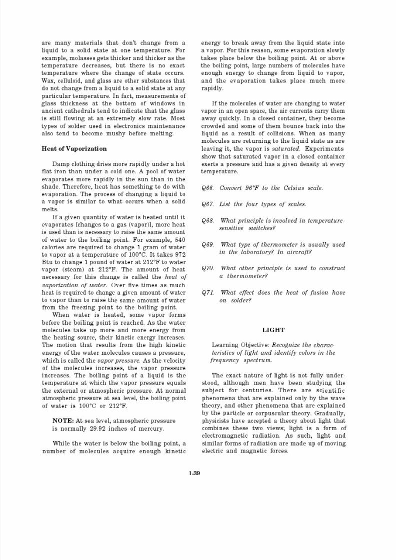
The inverse square law of light holds true for
undirected light only. For light that is directed,
the rate its intensity diminishes depends on the
rate of divergence of the beam.
Lumen. This unit is the amount of light
flowing through a solid angle of 1 radian from
a standard candle. The following example helps
explain the term lumen. If a light source of 1candlepower is placed in the center of a spherewith a radius of 1 foot, it illuminates every point
on the surface of the sphere at an intensity of
1 footcandle. Every square foot of the surface
receives 1 lumen of light. The total surface of the
sphere is found by the formula If the radiusof a sphere is 1 foot, the area is 4 x 3.1416 x 1
2
= 12.5664 square feet. Therefore, a source of 1
candlepower emits 12.5664 lumens.
The output of light bulbs is given either in
candlepower or in lumens. Since the light bulbmay not distribute the light equally in alldirections, the lumen is most frequently used.Light bulb manufacturers measure the light
output in all directions and specify its total outputin lumens. When the total output in lumens isknown, the average candlepower is computed by
dividing the total output in lumens by
(12.5664).
Lux. The lux is the illumination given to a
surface 1 meter away from a 1-candlepower sourceand is sometimes called a meter-candle.
Phot. The phot is the illumination given to
a surface 1 centimeter away from a 1-candlepowersource and is sometimes called a centimeter-
candle.
Luminance. Luminance (or brightness) refers
to the light a surface gives off in the direction of
the observer. The lambert is the unit of luminanceequal to the uniform luminance of a perfectly
diffusing surface that emits or reflects light at the
rate of 1 lumen per square centimeter. For a
perfectly reflecting and perfectly diffusing surface,the number of lamberts is equal to the numberof phots (incident light).
Q72.
Q73.
Q74.
Q75.
Q76.
List the effects on light waves when they
meet a substance.
What is meant b y the term luminous
intensity?
What is meant by the term intensity of
illumination?
What is measured by the footcandle?
What term is usually used to describe the
output of a light bulb?
1-42

8/14/2019 US Navy Course NAVEDTRA 14028 - Aviation Electronics Technician-Basic
http://slidepdf.com/reader/full/us-navy-course-navedtra-14028-aviation-electronics-technician-basic 48/415
Reflection
Light waves obey the law of reflection the same way as other types of waves.
Optical devices that reflect light are generally classed as mirrors. They are
a polished opaque surface, or they are a specially coated glass. Glass mirrorsrefract as well as reflect; however, if the glass is of good quality and not
excessively thick, the refraction causes no trouble. The following discussion
is based on the mirror.
Basically, the reflector is used to change the
direction of a light beam. The angle of thereflected light is changed to a greater or lesser
degree by changing the angle at which the incidentlight impinges upon the mirror.
Changing direction.
The reflector is also used to focus a beam of light. The focusing action of a concave mirror is
indicated. The point of focus may be made anyconvenient distance from the reflector by proper
selection of the arc of curvature of the mirror;the sharper the curvature, the shorter the focallength.
Focusing a beam.
The reflector can be used to intensify the
illumination of an area. The flashlight is anexample of this application. You can see that thelight source (bulb) is located approximately at the
principal focus point, and that all rays reflectedfrom the surface are parallel. You can also seethat the reflector does not concentrate all the rays,
and some are transmitted without being reflected
and are not included in the principal beam.
Illuminating an area.
1-43
8/14/2019 US Navy Course NAVEDTRA 14028 - Aviation Electronics Technician-Basic
http://slidepdf.com/reader/full/us-navy-course-navedtra-14028-aviation-electronics-technician-basic 49/415
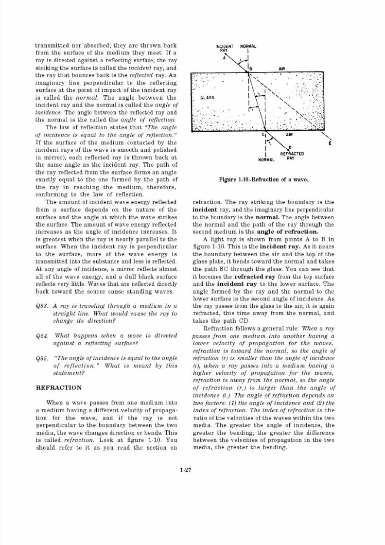
Refraction
As light passes through a transparent substance, it travels in a straightline. When it passes into or out of that substance, it is refracted like otherwaves. Refraction of light occurs because light travels at different velocities
in different transparent media. To make it easier to predict the outcome of specific applications, many transparent substances have been tested forrefractive effectiveness. The ratio of the speed of light in air to its speed in
each transparent substance is called the index of refraction for that substance.
For example, light travels about one and one-half times as fast in air as it
does in glass, so the index of refraction of glass is about 1.5. When the law
of refraction is used in connection with light, a denser medium refers to amedium with a higher index of refraction.
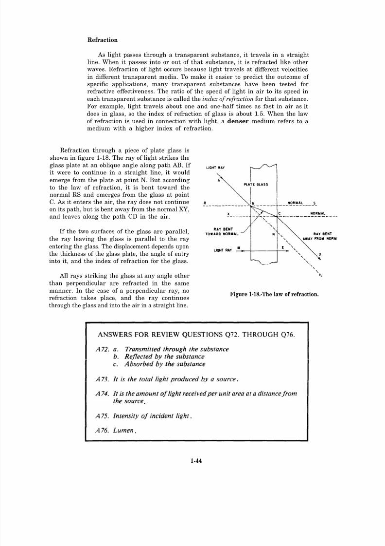
Refraction through a piece of plate glass is
shown in figure 1-18. The ray of light strikes the
glass plate at an oblique angle along path AB. If it were to continue in a straight line, it would
emerge from the plate at point N. But according
to the law of refraction, it is bent toward thenormal RS and emerges from the glass at pointC. As it enters the air, the ray does not continueon its path, but is bent away from the normal XY,and leaves along the path CD in the air.
If the two surfaces of the glass are parallel,
the ray leaving the glass is parallel to the ray
entering the glass. The displacement depends uponthe thickness of the glass plate, the angle of entryinto it, and the index of refraction for the glass.
All rays striking the glass at any angle other
than perpendicular are refracted in the same
manner. In the case of a perpendicular ray, norefraction takes place, and the ray continues
Figure 1-18.-The law of refraction.
through the glass and into the air in a straight line.
1-44
.
.
.
.
8/14/2019 US Navy Course NAVEDTRA 14028 - Aviation Electronics Technician-Basic
http://slidepdf.com/reader/full/us-navy-course-navedtra-14028-aviation-electronics-technician-basic 50/415
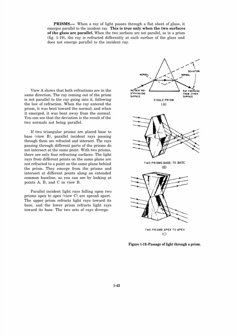
PRISMS.— When a ray of light passes through a flat sheet of glass, itemerges parallel to the incident ray. This is true only when the two surfaces
of the glass are parallel. When the two surfaces are not parallel, as in a prism
(fig. 1-19), the ray is refracted differently at each surface of the glass anddoes not emerge parallel to the incident ray.
View A shows that both refractions are in thesame direction. The ray coming out of the prismis not parallel to the ray going into it, followingthe law of refraction. When the ray entered theprism, it was bent toward the normal; and when
it emerged, it was bent away from the normal.
You can see that the deviation is the result of thetwo normals not being parallel.
If two triangular prisms are placed base to
base (view B), parallel incident rays passingthrough them are refracted and intersect. The rays
passing through different parts of the prisms donot intersect at the same point. With two prisms,
there are only four refracting surfaces. The light
rays from different points on the same plane are
not refracted to a point on the same plane behind
the prism. They emerge from the prisms andintersect at different points along an extended
common baseline, as you can see by looking atpoints A, B, and C in view B.
Parallel incident light rays falling upon twoprisms apex to apex (view C) are spread apart.
The upper prism refracts light rays toward its
base, and the lower prism refracts light rays
toward its base. The two sets of rays diverge.
Figure 1-19.-Passage of light through a prism.
1-45
8/14/2019 US Navy Course NAVEDTRA 14028 - Aviation Electronics Technician-Basic
http://slidepdf.com/reader/full/us-navy-course-navedtra-14028-aviation-electronics-technician-basic 51/415
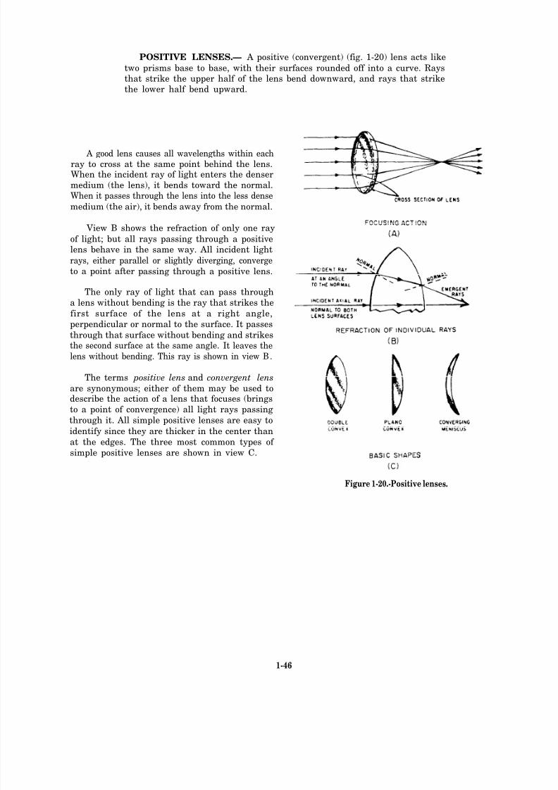
POSITIVE LENSES.— A positive (convergent) (fig. 1-20) lens acts like
two prisms base to base, with their surfaces rounded off into a curve. Raysthat strike the upper half of the lens bend downward, and rays that strikethe lower half bend upward.
A good lens causes all wavelengths within eachray to cross at the same point behind the lens.When the incident ray of light enters the denser
medium (the lens), it bends toward the normal.When it passes through the lens into the less dense
medium (the air), it bends away from the normal.
View B shows the refraction of only one ray
of light; but all rays passing through a positivelens behave in the same way. All incident light
rays, either parallel or slightly diverging, converge
to a point after passing through a positive lens.
The only ray of light that can pass through
a lens without bending is the ray that strikes the
first surface of the lens at a right angle,
perpendicular or normal to the surface. It passes
through that surface without bending and strikesthe second surface at the same angle. It leaves the
lens without bending. This ray is shown in view B.
The terms positive lens and convergent lens
are synonymous; either of them may be used todescribe the action of a lens that focuses (brings
to a point of convergence) all light rays passing
through it. All simple positive lenses are easy to
identify since they are thicker in the center than
at the edges. The three most common types of
simple positive lenses are shown in view C.
Figure 1-20.-Positive lenses.
1-46
8/14/2019 US Navy Course NAVEDTRA 14028 - Aviation Electronics Technician-Basic
http://slidepdf.com/reader/full/us-navy-course-navedtra-14028-aviation-electronics-technician-basic 52/415
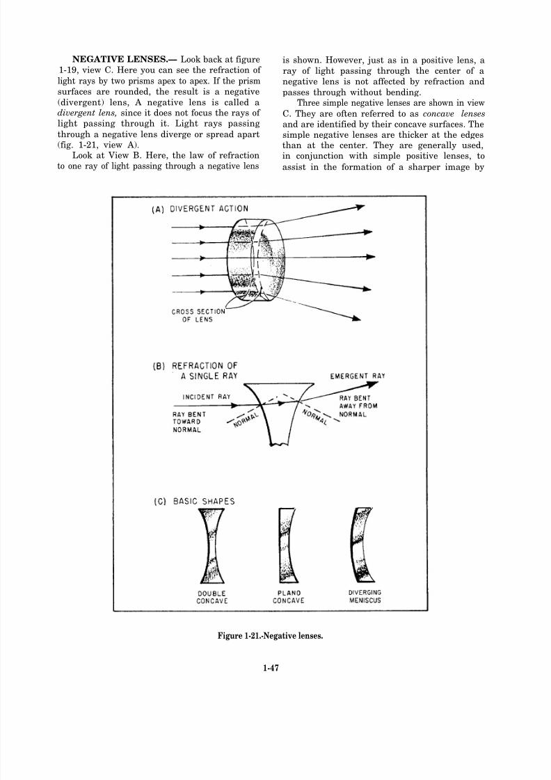
NEGATIVE LENSES.— Look back at figure1-19, view C. Here you can see the refraction of
light rays by two prisms apex to apex. If the prism
surfaces are rounded, the result is a negative
(divergent) lens, A negative lens is called adivergent lens, since it does not focus the rays of light passing through it. Light rays passing
through a negative lens diverge or spread apart(fig. 1-21, view A).
Look at View B. Here, the law of refractionto one ray of light passing through a negative lens
is shown. However, just as in a positive lens, a
ray of light passing through the center of a
negative lens is not affected by refraction and
passes through without bending.Three simple negative lenses are shown in view
C. They are often referred to as concave lenses
and are identified by their concave surfaces. The
simple negative lenses are thicker at the edgesthan at the center. They are generally used,in conjunction with simple positive lenses, to
assist in the formation of a sharper image by
Figure 1-21.-Negative lenses.
1-47
8/14/2019 US Navy Course NAVEDTRA 14028 - Aviation Electronics Technician-Basic
http://slidepdf.com/reader/full/us-navy-course-navedtra-14028-aviation-electronics-technician-basic 53/415
eliminating or subduing various defects presentin an uncorrected simple positive lens.
Q77. What are the principle uses of reflectors?
Q78. What happens when light passes through
a transparent substance?
Q79. List the objects that act as refractors.
FREQUENCIES AND COLOR
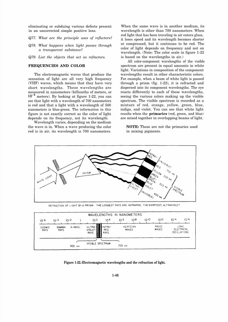
The electromagnetic waves that produce the
sensation of light are all very high frequency(VHF) waves, which means that they have very
short wavelengths. These wavelengths are
measured in nanometers (billionths of meters, or
meters). By looking at figure 1-22, you can
see that light with a wavelength of 700 nanometersis red and that a light with a wavelength of 500nanometers is blue-green. The information in this
figure is not exactly correct as the color of lightdepends on its frequency, not its wavelength.
Wavelength varies, depending on the medium
the wave is in. When a wave producing the color
red is in air, its wavelength is 700 nanometers.
When the same wave is in another medium, its
wavelength is other than 700 nanometers. When
red light that has been traveling in air enters glass,it loses speed and its wavelength becomes shorter
or compressed, but it continues to be red. The
color of light depends on frequency and not onwavelength. (Note: The color scale in figure 1-22
is based on the wavelengths in air.) All color-component wavelengths of the visible
spectrum are present in equal amounts in white
light. Variations in composition of the componentwavelengths result in other characteristic colors.
For example, when a beam of white light is passedthrough a prism (fig. 1-22), it is refracted and
dispersed into its component wavelengths. The eye
reacts differently to each of these wavelengths,
seeing the various colors making up the visiblespectrum. The visible spectrum is recorded as amixture of red, orange, yellow, green, blue,indigo, and violet. You can see that white light
results when the primaries (red, green, and blue)are mixed together in overlapping beams of light.
NOTE: These are not the primaries used
in mixing pigments.
Figure 1-22.-Electromagnetic wavelengths and the refraction of light.
1-48
8/14/2019 US Navy Course NAVEDTRA 14028 - Aviation Electronics Technician-Basic
http://slidepdf.com/reader/full/us-navy-course-navedtra-14028-aviation-electronics-technician-basic 54/415

8/14/2019 US Navy Course NAVEDTRA 14028 - Aviation Electronics Technician-Basic
http://slidepdf.com/reader/full/us-navy-course-navedtra-14028-aviation-electronics-technician-basic 55/415

8/14/2019 US Navy Course NAVEDTRA 14028 - Aviation Electronics Technician-Basic
http://slidepdf.com/reader/full/us-navy-course-navedtra-14028-aviation-electronics-technician-basic 56/415
8/14/2019 US Navy Course NAVEDTRA 14028 - Aviation Electronics Technician-Basic
http://slidepdf.com/reader/full/us-navy-course-navedtra-14028-aviation-electronics-technician-basic 57/415
8/14/2019 US Navy Course NAVEDTRA 14028 - Aviation Electronics Technician-Basic
http://slidepdf.com/reader/full/us-navy-course-navedtra-14028-aviation-electronics-technician-basic 58/415
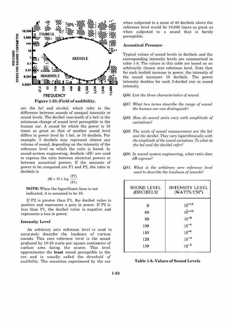
Figure 1-23.-Field of audibility.
are the bel and decibel,
NOTE: When the logarithmic base is not
indicated, it is assumed to be 10.
If P2 is greater than P1, the decibel value ispositive and represents a gain in power. If P2 is
less than P1, the decibel value is negative andrepresents a loss in power.
Intensity Level
An arbitrary zero reference level is used toaccurately describe the loudness of varioussounds. This zero reference level is the soundproduced by 10-16 watts per square centimeter of surface area facing the source. This levelapproximates the least sound perceptible to the
ear and is usually called the threshold of audibility. The sensation experienced by the ear
when subjected to a noise of 40 decibels above thereference level would be 10,000 times as great aswhen subjected to a sound that is barelyperceptible.
Acoustical Pressure
Typical values of sound levels in decibels and the
corresponding intensity levels are summarized intable 1-8. The values in this table are based on anarbitrarily chosen zero reference level. Note thatfor each tenfold increase in power, the intensity of the sound increases 10 decibels. The powerintensity doubles for each 3-decibel rise in soundintensity.
Q86. List the three characteristics of sound.
Q87. What two terms describe the range of soundthe human ear can distinguish?
Q88. How do sound units vary with amplitude of variations?
Q89. The units of sound measurement are the beland the decibel. They vary logarithmically with
the amplitude of the sound variations. To what do
the bel and the decibel refer?
Q90. In sound-system engineering, what ratio doesdB express?
Q91. What is the arbitrary zero reference level
used to describe the loudness of sounds?
Table 1-8.-Values of Sound Levels
1-53
which refer to thedifference between sounds of unequal intensity orsound levels. The decibel (one-tenth of a bel) is theminimum change of sound level perceptible to thehuman ear. A sound for which the power is 10times as great as that of another sound level
differs in power level by 1 bel, or 10 decibels. Forexample, 5 decibels may represent almost any
volume of sound, depending on the intensity of the
reference level on which the ratio is based. Insound-system engineering, decibels (dB) are usedto express the ratio between electrical powers or
between acoustical powers, If the amounts of power to be compared are P1 and P2, the ratio in
decibels isdB = 10 x log
(P2)___ .
(P1)
8/14/2019 US Navy Course NAVEDTRA 14028 - Aviation Electronics Technician-Basic
http://slidepdf.com/reader/full/us-navy-course-navedtra-14028-aviation-electronics-technician-basic 59/415
Power Ratio
The decibel is used to express an electrical
power ratio, such as the gain of an amplifier, the
output of a microphone, or the power in a circuitcompared to an arbitrarily chosen reference powerlevel. The value of decibels is often computedfrom the voltage ratio or the current ratio squared.
These values are proportional to the power ratio
for equal values of resistance. If the resistancesare not equal, a correction must be made. To findthe number of decibels from the voltage ratio,
assuming that the resistances are equal, substitutefor P in the basic equation:
To find the number of decibels from the
current ratio, assuming that the resistances areequal, substitute 1
2for P in the basic equation:
The power level of an electrical signal is often
expressed in decibels above or below a power levelof 0.001 watt (1 milliwatt) as
where, dBm is the power level above 1 milliwatt
in decibels, and P is the power in watts.The volume level of an electrical signal
comprising speech, music, or other complex tones
is measured by a specially calibrated voltmetercalled a volume indicator. The volume levels read
with this indicator are read in v units (vu), the
number being numerically equal to the number
of decibels above or below the reference volumelevel. Zero vu represents a power of 1 milliwattdissipated in an arbitrarily chosen load resistance
of 600 ohms, which corresponds to a voltage of 0.7746 volt. Therefore, when the vu meter is con-
nected to a 600-ohm load, vu readings in decibelsare used as a direct measure of power above orbelow 1 milliwatt. For any other value of
resistance, the following correction must be added
to the vu reading to obtain the correct vu value:
where vu is the actual volume level, and R is the
actual load, or resistance, across which the vumeasurement is made.
1-54
8/14/2019 US Navy Course NAVEDTRA 14028 - Aviation Electronics Technician-Basic
http://slidepdf.com/reader/full/us-navy-course-navedtra-14028-aviation-electronics-technician-basic 60/415
8/14/2019 US Navy Course NAVEDTRA 14028 - Aviation Electronics Technician-Basic
http://slidepdf.com/reader/full/us-navy-course-navedtra-14028-aviation-electronics-technician-basic 61/415

8/14/2019 US Navy Course NAVEDTRA 14028 - Aviation Electronics Technician-Basic
http://slidepdf.com/reader/full/us-navy-course-navedtra-14028-aviation-electronics-technician-basic 62/415
motion of the system in this case is called a forced
vibration.If the force is slowed from 125 vibrations per
second to the shaft’s natural frequency of 25 vibrations per second, the amplitude of vibration
becomes very large. The amplitude builds up to
a point where the driving force is enough to
overcome the inertia of the system. When theseconditions exist, the system is said to be inresonance with the driving force, and sound waves
are produced by this vibration. A common example of resonance is f ound in
a crystal oscillator circuit. When an alternating voltage is applied to a crystal that has the same
mechanical (resonant) frequency as the applied voltage, it vibrates, and only a small applied
voltage is needed to sustain vibration. In turn, the
crystal generates a relatively large voltage at itsresonant frequency.
Q95. What is the effect of excessive reverberation
in a large area when a loudspeaker is being
used?
Q96. Describe action that can be taken to lessen
or eliminate reverberation in a large area,such as a hangar deck.
Q97. Describe the effect of b eat frequency.
Q98. Why is resonance potentially a serious
problem?
1-57

8/14/2019 US Navy Course NAVEDTRA 14028 - Aviation Electronics Technician-Basic
http://slidepdf.com/reader/full/us-navy-course-navedtra-14028-aviation-electronics-technician-basic 63/415
1-58
.
.

8/14/2019 US Navy Course NAVEDTRA 14028 - Aviation Electronics Technician-Basic
http://slidepdf.com/reader/full/us-navy-course-navedtra-14028-aviation-electronics-technician-basic 64/415
8/14/2019 US Navy Course NAVEDTRA 14028 - Aviation Electronics Technician-Basic
http://slidepdf.com/reader/full/us-navy-course-navedtra-14028-aviation-electronics-technician-basic 65/415
Figure 2-1.-Electromagnetic spectrum.
2-2
8/14/2019 US Navy Course NAVEDTRA 14028 - Aviation Electronics Technician-Basic
http://slidepdf.com/reader/full/us-navy-course-navedtra-14028-aviation-electronics-technician-basic 66/415
8/14/2019 US Navy Course NAVEDTRA 14028 - Aviation Electronics Technician-Basic
http://slidepdf.com/reader/full/us-navy-course-navedtra-14028-aviation-electronics-technician-basic 67/415
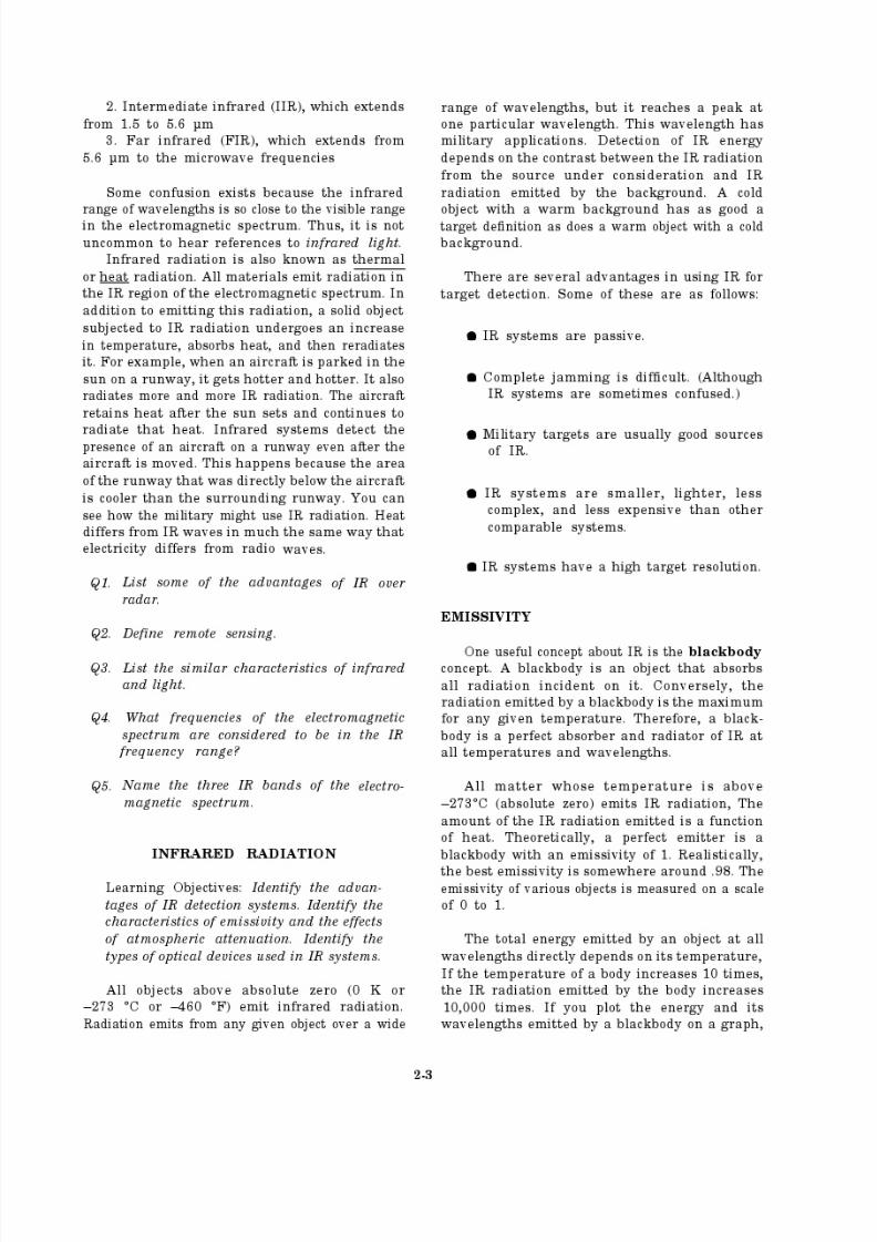
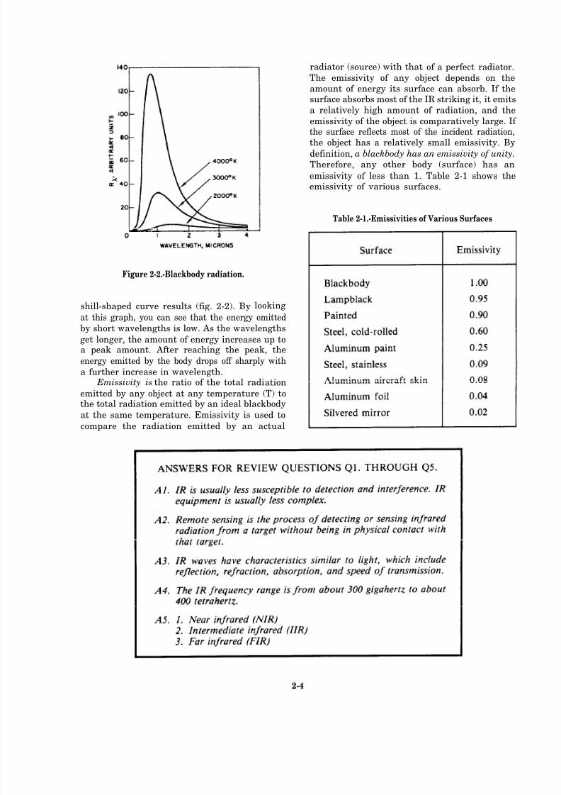
Figure 2-2.-Blackbody radiation.
shill-shaped curve results (fig. 2-2). By looking
at this graph, you can see that the energy emitted
by short wavelengths is low. As the wavelengths
get longer, the amount of energy increases up toa peak amount. After reaching the peak, the
energy emitted by the body drops off sharply with
a further increase in wavelength. Emissivity is the ratio of the total radiation
emitted by any object at any temperature (T) tothe total radiation emitted by an ideal blackbody
at the same temperature. Emissivity is used tocompare the radiation emitted by an actual
radiator (source) with that of a perfect radiator.
The emissivity of any object depends on the
amount of energy its surface can absorb. If thesurface absorbs most of the IR striking it, it emits
a relatively high amount of radiation, and the
emissivity of the object is comparatively large. If the surface reflects most of the incident radiation,
the object has a relatively small emissivity. Bydefinition, a blackbody has an emissivity of unity.
Therefore, any other body (surface) has an
emissivity of less than 1. Table 2-1 shows theemissivity of various surfaces.
Table 2-1.-Emissivities of Various Surfaces
2-4
8/14/2019 US Navy Course NAVEDTRA 14028 - Aviation Electronics Technician-Basic
http://slidepdf.com/reader/full/us-navy-course-navedtra-14028-aviation-electronics-technician-basic 68/415
The basic laws that describe the characteristics
of IR were first developed for blackbody radiation(the ideal case). Then they were modified todescribe radiation from any source.
Temperature is the most important parameter
in determining the IR characteristics of any body.
As the temperature of an object changes, two
specific changes in the IR characteristics takeplace:
1. the wavelength where peak radiation occurs
shifts, and2. the total energy radiated varies with the
fourth power of the temperature.
There are two laws that describe the relation-
ship between these IR characteristics.
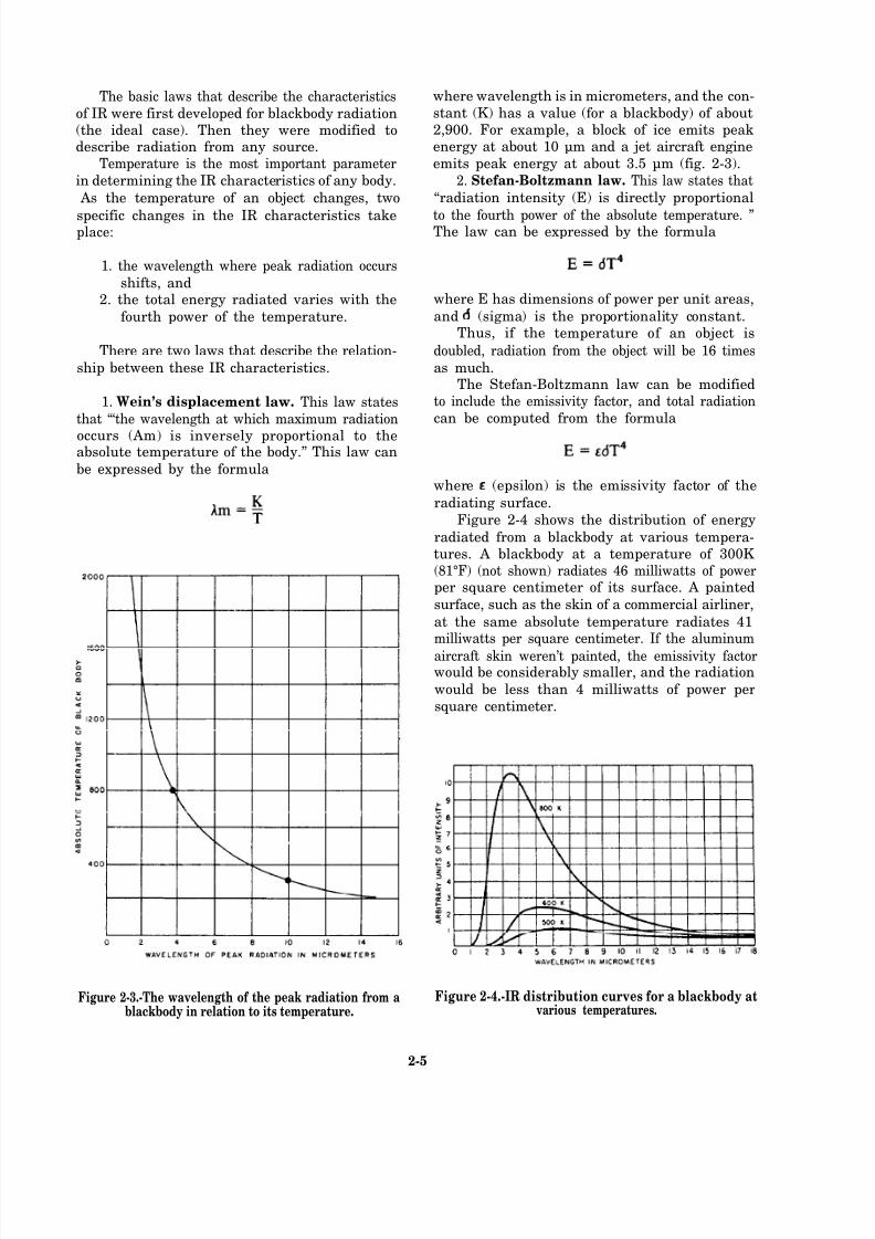
1. Wein’s displacement law. This law states
that “‘the wavelength at which maximum radiation
occurs (Am) is inversely proportional to theabsolute temperature of the body.” This law can
be expressed by the formula
Figure 2-3.-The wavelength of the peak radiation from ablackbody in relation to its temperature.
where wavelength is in micrometers, and the con-
stant (K) has a value (for a blackbody) of about2,900. For example, a block of ice emits peakenergy at about 10 µm and a jet aircraft engine
emits peak energy at about 3.5 µm (fig. 2-3).
2. Stefan-Boltzmann law. This law states that
“radiation intensity (E) is directly proportional
to the fourth power of the absolute temperature. ”The law can be expressed by the formula
where E has dimensions of power per unit areas,
and (sigma) is the proportionality constant.Thus, if the temperature of an object is
doubled, radiation from the object will be 16 times
as much.The Stefan-Boltzmann law can be modified
to include the emissivity factor, and total radiation
can be computed from the formula
where (epsilon) is the emissivity factor of the
radiating surface.
Figure 2-4 shows the distribution of energy
radiated from a blackbody at various tempera-tures. A blackbody at a temperature of 300K (81°F) (not shown) radiates 46 milliwatts of powerper square centimeter of its surface. A painted
surface, such as the skin of a commercial airliner,
at the same absolute temperature radiates 41milliwatts per square centimeter. If the aluminum
aircraft skin weren’t painted, the emissivity factorwould be considerably smaller, and the radiation
would be less than 4 milliwatts of power per
square centimeter.
Figure 2-4.-IR distribution curves for a blackbody atvarious temperatures.
2-5

8/14/2019 US Navy Course NAVEDTRA 14028 - Aviation Electronics Technician-Basic
http://slidepdf.com/reader/full/us-navy-course-navedtra-14028-aviation-electronics-technician-basic 69/415
8/14/2019 US Navy Course NAVEDTRA 14028 - Aviation Electronics Technician-Basic
http://slidepdf.com/reader/full/us-navy-course-navedtra-14028-aviation-electronics-technician-basic 70/415
OPTICAL DEVICES
Optical devices are used in front-end optics to
gather and focus the infrared radiation upon the
detector. They can be used because of the
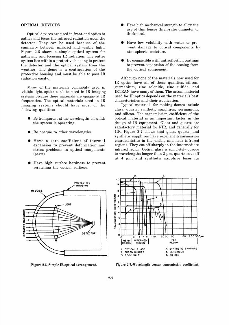
similarity between infrared and visible light.Figure 2-6 shows a simple optical system for
gathering and focusing IR radiation. The entiresystem lies within a protective housing to protect
the detector and the optical system from theweather. The dome is a continuation of the
protective housing and must be able to pass IRradiation easily.
Many of the materials commonly used in visible light optics can’t be used in IR imaging
systems because these materials are opaque at IRfrequencies. The optical materials used in IR
imaging systems should have most of thefollowing qualities:
Be transparent at the wavelengths on which
the system is operating.
Be opaque to other wavelengths.
Have a zero coefficient of thermalexpansion to prevent def ormation and
stress problems in optical components(parts).
Have high surface hardness to prevent
scratching the optical surfaces.
Figure 2-6.-Simple IR optical arrangement.
Have high mechanical strength to allow theuse of thin lenses (high-ratio diameter tothickness).
Have low volubility with water to pre-
vent damage to optical components by
atmospheric moisture.
Be compatible with antireflection coatingsto prevent separation of the coating from
the optical component.
Although none of the materials now used for
IR optics have all of these qualities, silicon,germanium, zinc selenide, zinc sulfide, and
IRTRAN have many of them. The actual material
used for IR optics depends on the material’s best
characteristics and their application.Typical materials for making domes include
glass, quartz, synthetic sapphires, germanium,
and silicon. The transmission coefficient of theoptical material is an important factor in the
design of IR equipment. Glass and quartz aresatisfactory material for NIR, and generally forIIR, Figure 2-7 shows that glass, quartz, and
synthetic sapphires have excellent transmissioncharacteristics in the visible and near infraredregions. They cut off sharply in the intermediate
infrared region. Optical glass is completely opaqueto wavelengths longer than 3 µm, quartz cuts off
at 4 µm, and synthetic sapphire loses its
Figure 2-7.-Wavelength versus transmission coefficient.
2-7

8/14/2019 US Navy Course NAVEDTRA 14028 - Aviation Electronics Technician-Basic
http://slidepdf.com/reader/full/us-navy-course-navedtra-14028-aviation-electronics-technician-basic 71/415
8/14/2019 US Navy Course NAVEDTRA 14028 - Aviation Electronics Technician-Basic
http://slidepdf.com/reader/full/us-navy-course-navedtra-14028-aviation-electronics-technician-basic 72/415
8/14/2019 US Navy Course NAVEDTRA 14028 - Aviation Electronics Technician-Basic
http://slidepdf.com/reader/full/us-navy-course-navedtra-14028-aviation-electronics-technician-basic 73/415
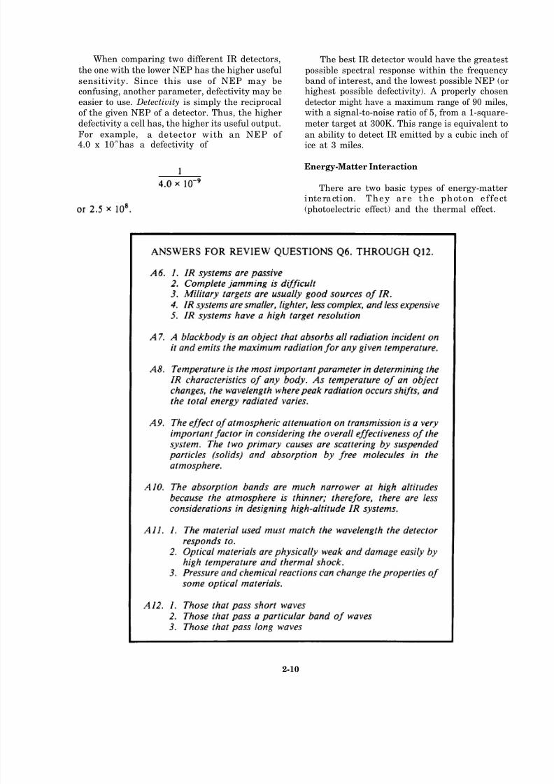
When comparing two different IR detectors,
the one with the lower NEP has the higher useful
sensitivity. Since this use of NEP may beconfusing, another parameter, defectivity may beeasier to use. Detectivity is simply the reciprocal
of the given NEP of a detector. Thus, the higherdefectivity a cell has, the higher its useful output.
For example, a detector with an NEP of 4.0 x 10⁻⁹
has a defectivity of
The best IR detector would have the greatest
possible spectral response within the frequencyband of interest, and the lowest possible NEP (orhighest possible defectivity). A properly chosen
detector might have a maximum range of 90 miles,with a signal-to-noise ratio of 5, from a 1-square-
meter target at 300K . This range is equivalent to
an ability to detect IR emitted by a cubic inch of ice at 3 miles.
Energy-Matter Interaction
There are two basic types of energy-matterinteraction. They are the photon effect
(photoelectric effect) and the thermal effect.
2-10

8/14/2019 US Navy Course NAVEDTRA 14028 - Aviation Electronics Technician-Basic
http://slidepdf.com/reader/full/us-navy-course-navedtra-14028-aviation-electronics-technician-basic 74/415
PHOTON EFFECT.— In the photon effect
energy-matter interaction, the photons of the
radiant energy interact directly with the electronsin the detector material. Usually, detectors using
the photon effect use semiconductor material.There are three specific types of photon effect
detection.
The three major types of photodetectors arethe photoconductive, photovoltaic, and photo-emissive types. The signal-to-noise ratio of eachof these detectors is the limiting factor indetermining its ef fectiveness.
1. Photoconductive. Photoconductivity is the
most widely used photon effect. It is also known
as the internal photoelectric effect. (See fig. 2-8.)Radiant energy changes the electrical conductivity
of the detector material. An electrical circuit
measures the change in the conductivity.
The photoconductor contains a semiconductorcrystal that absorbs the photon energy from the
radiation, which strikes the surface of the
crystal. This changes the crystal’s resistance orconductivity. Several different materials are usedfor this type of detector, including lead sulfide,lead telluride, lead selenide, and cadmium sulfide.
Gold-doped germanium is a good detectormaterial. However, there are some difficulties
such as long time constants.
2. Photovoltaic effect. In the photovoltaic
effect (fig. 2-9), the radiant signal causes a
potential difference across a PN junction. The
Figure 2-8.-Photoconductive detector circuit and graphicsymbols.
Figure 2-9.-Photovoltaic effect and graphic symbol.
photocurrent (current generated by light) adds tothe dark current (current that flows with no
radiant input). The total current is proportionalto the amount of light that falls on the detector.
The photovoltaic effect uses a photovoltaic cell
similar to a solar cell. This is a semiconductor with
a high-resistance, photosensitive barrier between
two layers. When exposed to IR, a potentialdifference builds up across the two layers of thecell.
3. Photoemissive. The photoemissive ef fect
(fig. 2-10) is also the external photoelectric effect.
The action of the radiation causes the emission
of an electron from the surface of the photo-
cathode in the surrounding space.
Figure 2-10.-Photoemissive effect and graphic symbol.
2-11

8/14/2019 US Navy Course NAVEDTRA 14028 - Aviation Electronics Technician-Basic
http://slidepdf.com/reader/full/us-navy-course-navedtra-14028-aviation-electronics-technician-basic 75/415
The photoemissive cell’s cathode is exposed
to IR and causes electronic emission. The number
of emitted electrons depends on the intensity of
the IR striking the cathode.
THERMAL EFFECT. —The thermal effect
type of energy-matter interaction involves the
absorption of radiant energy in the detector. This
results in a temperature increase in the detector
element. You detect the radiation by monitoring
the temperature increase in the detector. Both theelemental and imaging forms of detectors use the
thermal effect.
THERMAL DETECTORS
Thermal detection is the sensing of the change
in temperature of the detector material as a resultof IR striking its surface. There are three differenttypes of sensing elements employed in modern
thermal detectors.
1. The thermopile, a series combination of
several thermocouples
2. The bolometer, which senses changes in
resistance of the detector material
3. The pneumatic cell, which uses the
expansion of a gas as an indicator
Thermocouple
One of the basic heat detectors is the
thermocouple. When applying heat to the junctionof two dissimilar metals such as iron and copper,
a measurable voltage is generated between them.Figure 2-11 shows a basic thermocouple.
The voltage difference across the thermo-
couple is small. However, you can increase the
sensitivity to a point where the thermocouple
becomes useful as an IR detector. You can obtain
an increase in sensitivity by connecting or stackingseveral thermocouples in series, forming a
thermopile. The complete thermopile action is likeconnecting several flashlight cells in series; the
output of each thermocouple adds to the output
of the others. For example, 10 thermocouples,
with individual outputs of 0.001 volt, have a total
output of 0.01 volt when connected in series.
The effective sensitivity increases further by
mounting a thermopile at the focal point of a
parabolic reflector. When using this method, the
reflector focuses the IR from the target onto the
thermopile.
Bolometer
A bolometer is a very sensitive device whose
resistance will vary, depending on the IR
exposure. There are two main classes of
bolometers—the barretter and the thermistor.
A barretter is a variable resistor made of ashort length of very fine wire (usually platinum)
that has a positive temperature coefficient of
resistance. (A substance has a positive temperaturecoefficient if its resistance increases with an
Figure 2-11.-Thermocouple.
2-12
Figure 2-12.-Various thermistors.
8/14/2019 US Navy Course NAVEDTRA 14028 - Aviation Electronics Technician-Basic
http://slidepdf.com/reader/full/us-navy-course-navedtra-14028-aviation-electronics-technician-basic 76/415
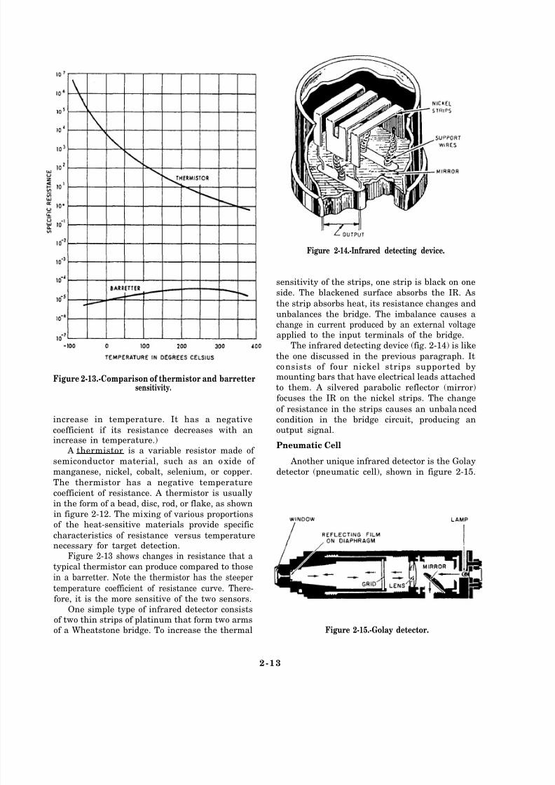
Figure 2-13.-Comparison of thermistor and barrettersensitivity.
increase in temperature. It has a negative
coefficient if its resistance decreases with anincrease in temperature.)
A thermistor is a variable resistor made of
semiconductor material, such as an oxide of
manganese, nickel, cobalt, selenium, or copper.
The thermistor has a negative temperature
coefficient of resistance. A thermistor is usually
in the form of a bead, disc, rod, or flake, as shown
in figure 2-12. The mixing of various proportions
of the heat-sensitive materials provide specific
characteristics of resistance versus temperaturenecessary for target detection.
Figure 2-13 shows changes in resistance that atypical thermistor can produce compared to those
in a barretter. Note the thermistor has the steeper
temperature coefficient of resistance curve. There-fore, it is the more sensitive of the two sensors.
One simple type of infrared detector consists
of two thin strips of platinum that form two arms
of a Wheatstone bridge. To increase the thermal
Figure 2-14.-Infrared detecting device.
sensitivity of the strips, one strip is black on one
side. The blackened surface absorbs the IR. As
the strip absorbs heat, its resistance changes and
unbalances the bridge. The imbalance causes a
change in current produced by an external voltageapplied to the input terminals of the bridge.
The infrared detecting device (fig. 2-14) is like
the one discussed in the previous paragraph. It
consists of four nickel strips supported bymounting bars that have electrical leads attached
to them. A silvered parabolic reflector (mirror)
focuses the IR on the nickel strips. The change
of resistance in the strips causes an unbalancedcondition in the bridge circuit, producing an
output signal.
Pneumatic Cell
Another unique infrared detector is the Golay
detector (pneumatic cell), shown in figure 2-15.
Figure 2-15.-Golay detector.
2-13

8/14/2019 US Navy Course NAVEDTRA 14028 - Aviation Electronics Technician-Basic
http://slidepdf.com/reader/full/us-navy-course-navedtra-14028-aviation-electronics-technician-basic 77/415

8/14/2019 US Navy Course NAVEDTRA 14028 - Aviation Electronics Technician-Basic
http://slidepdf.com/reader/full/us-navy-course-navedtra-14028-aviation-electronics-technician-basic 78/415

8/14/2019 US Navy Course NAVEDTRA 14028 - Aviation Electronics Technician-Basic
http://slidepdf.com/reader/full/us-navy-course-navedtra-14028-aviation-electronics-technician-basic 79/415
electronic circuit to process the information that
it provides. Also, each detector element requires
a preamplifier to boost the signal to a useful level.
SINGLE DETECTOR.— Another methodthat provides the operator with information is thesingle scanning detector (fig. 2-16, view B). Here,
there is one detector requiring one set of supporting circuitry. In this type of system, the
scanning of the image is across the detector so that
the detector can see the whole image. An optical
system supplies the scanning. This type of system
is adequate if real-time information is not
important, or if the object of interest is stationary
or not moving quickly.
Scene Disection System
The scene disection system scans the scene
image. There are many types of scanning—one
associated with each type of detector array. Asingle detector with one fast scan axis and oneslow scan can scan the scene rapidly in the
horizontal direction and slowly in the vertical
direction. A vertical linear array is scanned rapidly in
the horizontal direction. One detector elementscans one line of the image. In the linear array,
there is a space one element wide between each
element. The scan is one axis with an interlace.
After each horizontal scan, the mechanism shiftsthe image upward or downward one detector
element width. This allows the next scan to cover
any of the missed lines.Each system has an optimum configuration
of detector array and image disection. If thenumber of elements in the detector array are
increased, the system becomes more complicated.The cost of the system increases, and the reliability
of the system decreases. If you decrease thenumber of detectors, you reduce the amount of information that you can process. A compromise
between increasing the number of elements
(increased cost) and decreasing the number of elements (reduced information) is to use a lineararray scanned in one direction only. Each detector
2-16
8/14/2019 US Navy Course NAVEDTRA 14028 - Aviation Electronics Technician-Basic
http://slidepdf.com/reader/full/us-navy-course-navedtra-14028-aviation-electronics-technician-basic 80/415
8/14/2019 US Navy Course NAVEDTRA 14028 - Aviation Electronics Technician-Basic
http://slidepdf.com/reader/full/us-navy-course-navedtra-14028-aviation-electronics-technician-basic 81/415
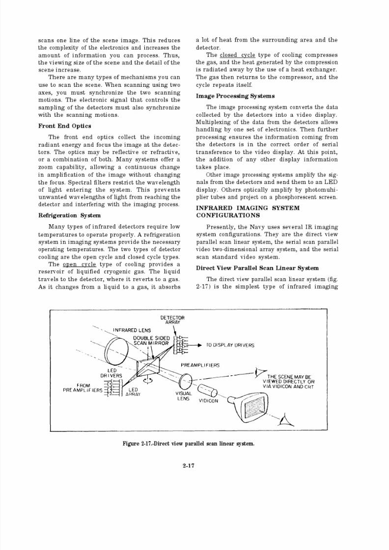
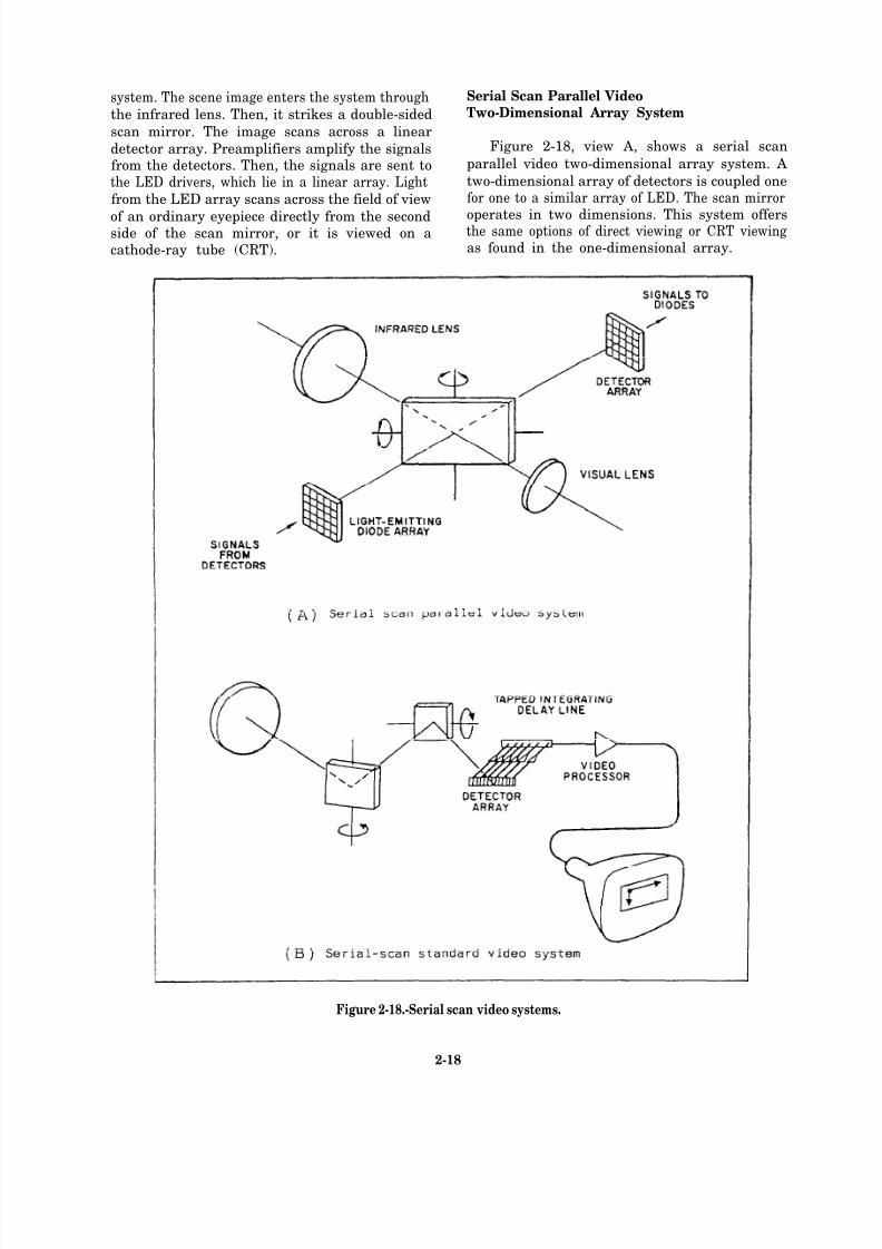
system. The scene image enters the system through Serial Scan Parallel Video
the infrared lens. Then, it strikes a double-sided Two-Dimensional Array System
scan mirror. The image scans across a linear
detector array. Preamplifiers amplify the signals Figure 2-18, view A, shows a serial scan
from the detectors. Then, the signals are sent to parallel video two-dimensional array system. A
the LED drivers, which lie in a linear array. Light two-dimensional array of detectors is coupled one
from the LED array scans across the field of view for one to a similar array of LED. The scan mirror
of an ordinary eyepiece directly from the second operates in two dimensions. This system offersside of the scan mirror, or it is viewed on a the same options of direct viewing or CRT viewing
cathode-ray tube (CRT). as found in the one-dimensional array.
Figure 2-18.-Serial scan video systems.
2-18
8/14/2019 US Navy Course NAVEDTRA 14028 - Aviation Electronics Technician-Basic
http://slidepdf.com/reader/full/us-navy-course-navedtra-14028-aviation-electronics-technician-basic 82/415
Serial Scan Standard Video System
Figure 2-18, view B, shows a serial scan
standard video system. Scanning of the incomingimage is done in two dimensions by a scan mirror
and an interlace mirror. The interlace mirror shiftsthe image one detector element width. This is
using a linear detector array. Preamplifiers
amplify the information from each detector.Then, it is sent to the delay circuitry for changing
into serial form. This circuitry samples each
detector at the appropriate time for correct length
of time, resulting in a serial output to the video
processor.
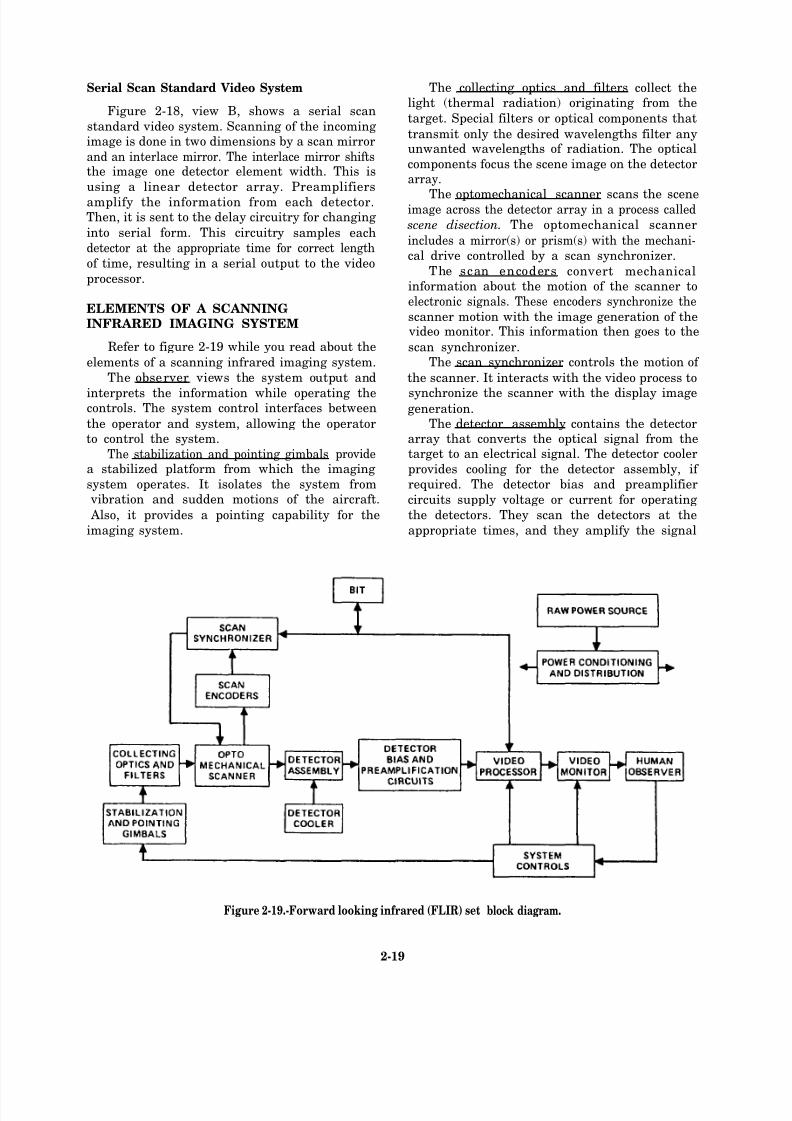
ELEMENTS OF A SCANNINGINFRARED IMAGING SYSTEM
Refer to figure 2-19 while you read about the
elements of a scanning infrared imaging system.
The observer views the system output and
interprets the information while operating thecontrols. The system control interfaces between
the operator and system, allowing the operatorto control the system.
The stabilization and pointing gimbals providea stabilized platform from which the imaging
system operates. It isolates the system from vibration and sudden motions of the aircraft.
Also, it provides a pointing capability for the
imaging system.
The collecting optics and filters collect thelight (thermal radiation) originating from the
target. Special filters or optical components that
transmit only the desired wavelengths filter anyunwanted wavelengths of radiation. The optical
components focus the scene image on the detectorarray.
The optomechanical scanner scans the sceneimage across the detector array in a process called
scene disection. The optomechanical scanner
includes a mirror(s) or prism(s) with the mechani-
cal drive controlled by a scan synchronizer.
The scan encoders convert mechanicalinformation about the motion of the scanner to
electronic signals. These encoders synchronize the
scanner motion with the image generation of the video monitor. This information then goes to the
scan synchronizer.The scan synchronizer controls the motion of
the scanner. It interacts with the video process to
synchronize the scanner with the display imagegeneration.
The detector assembly contains the detectorarray that converts the optical signal from thetarget to an electrical signal. The detector cooler
provides cooling for the detector assembly, if
required. The detector bias and preamplifier
circuits supply voltage or current for operating
the detectors. They scan the detectors at the
appropriate times, and they amplify the signal
Figure 2-19.-Forward looking infrared (FLIR) set
2-19
block diagram.
8/14/2019 US Navy Course NAVEDTRA 14028 - Aviation Electronics Technician-Basic
http://slidepdf.com/reader/full/us-navy-course-navedtra-14028-aviation-electronics-technician-basic 83/415

8/14/2019 US Navy Course NAVEDTRA 14028 - Aviation Electronics Technician-Basic
http://slidepdf.com/reader/full/us-navy-course-navedtra-14028-aviation-electronics-technician-basic 84/415
8/14/2019 US Navy Course NAVEDTRA 14028 - Aviation Electronics Technician-Basic
http://slidepdf.com/reader/full/us-navy-course-navedtra-14028-aviation-electronics-technician-basic 85/415
of heat flow depends upon the following physicalsituations:
a. The higher the temperature gradient,
the greater the rate of heat flow (the temperature
gradient is equal to the difference in temperatures
divided by the distance over which the heat must
flow).b. The larger the area across which the
heat is flowing, the higher the rate of heat flow.
c. The shorter the distance the heat mustflow, the higher the rate of heat flow.
Radiation is the transfer of energy by electro-
magnetic radiation. All bodies that have a
temperature greater than 0 K give off electro-
magnetic radiation. The higher the temperature,the greater the amount of radiation emitted.
2. The first law of thermodynamics states that“the change in the internal energy of a system is equal to the heat introduced into the system minus
the energy expended by the system when it doeswork on the environ merit.”
3. The second law of thermodynamics statesthat “a cyclic process must transfer heat from a
hot reservoir if it is to convert heat into energy.” Also, work must be done to transfer heat from
4. The third law of thermodynamics statesthat “it is not possible by any procedure, no
matter how idealized, to reduce the temperature
of any system to absolute zero in a finite numberof steps.”
Absolute zero is a limit that you can only
approach and never achieve. The lowest tempera-ture that has ever been attained is .00002 K. The
closer that a system gets to 0 K, the harder it isto get heat from the system.
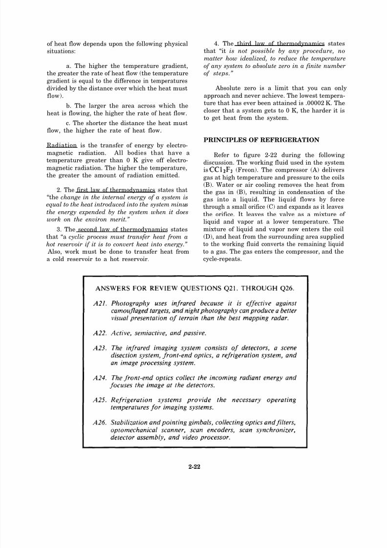
PRINCIPLES OF REFRIGERATION
Refer to figure 2-22 during the following
discussion. The working fluid used in the systemis (Freon). The compressor (A) delivers
gas at high temperature and pressure to the coils(B). Water or air cooling removes the heat from
the gas in (B), resulting in condensation of thegas into a liquid. The liquid flows by forcethrough a small orifice (C) and expands as it leaves
the orifice. It leaves the valve as a mixture of liquid and vapor at a lower temperature. The
mixture of liquid and vapor now enters the coil
(D), and heat from the surrounding area suppliedto the working fluid converts the remaining liquid
to a gas. The gas enters the compressor, and the
a cold reservoir to a hot reservoir. cycle-repeats.
2-22
8/14/2019 US Navy Course NAVEDTRA 14028 - Aviation Electronics Technician-Basic
http://slidepdf.com/reader/full/us-navy-course-navedtra-14028-aviation-electronics-technician-basic 86/415
Q27.
Q28.
Q29.
Q30.
Q31.
Figure 2-22.-Common refrigeration cycle.
Define cyrogenics and identify its tempera-ture range.
What happens when bodi es of differ ent
temperatures meet in thermal contact?
Energy is the driving force of the universe.What assumptions can you make about
energy?
Name the three types of heat flow.
How does heat flow through radiation?
LASERS
Learning Objectives: Identify the principlesof optics and lasers to include t erms,theory, and the partical theory of light.
Recognize the purpose of Q-switching andidentify solid-state laser types.
A laser is a device that produces or amplifies
ultraviolet, visible, or infrared radiation. This isdone by a process of controlled stimulatedemission. The word laser is an acronym for light
amplification by stimulated emission of radiation.The first lasers were used for surveying because
they accurately measured distance. Later, lasers
were used by the military. The initial military
application of the laser was for fire control. To
direct gunfire, the range to and the direction of the target must be determined. This is done by
the laser system. Then, the data gathered by the
laser system is used to direct the weapon system.Currently, the technology exists for laser
designation of the target for laser-guidedmunitions. Military laser systems have both a
range-finding capability for conventional
munitions and a designation for laser-guidedmunitions.
TERMS
There are several terms that you may find
useful when dealing with lasers. These are watts,
irradiance, joules, and radiant exposure.
Watts. A watt is a unit of power associated
with light energy.
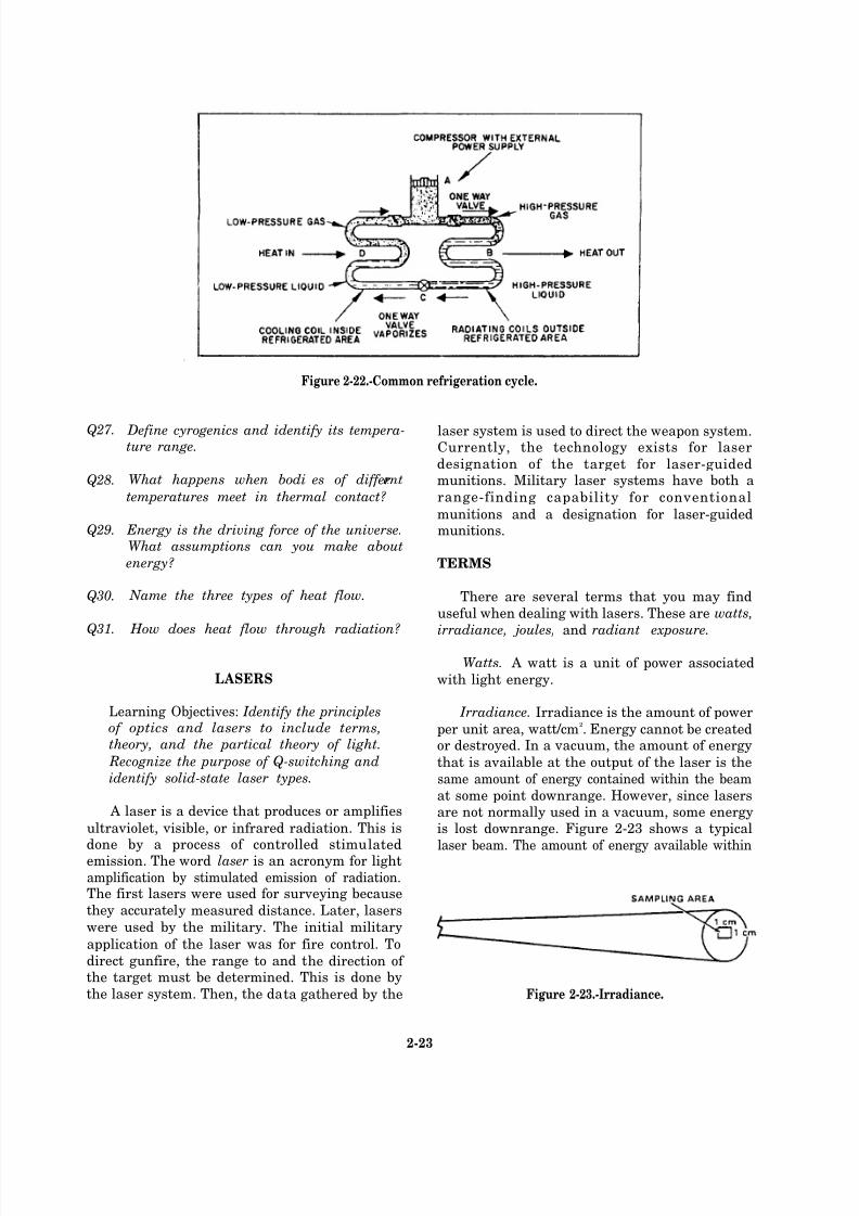
Irradiance. Irradiance is the amount of power
per unit area, watt/cm2. Energy cannot be created
or destroyed. In a vacuum, the amount of energy
that is available at the output of the laser is the
same amount of energy contained within the beam
at some point downrange. However, since lasersare not normally used in a vacuum, some energyis lost downrange. Figure 2-23 shows a typical
laser beam. The amount of energy available within
Figure 2-23.-Irradiance.
2-23

8/14/2019 US Navy Course NAVEDTRA 14028 - Aviation Electronics Technician-Basic
http://slidepdf.com/reader/full/us-navy-course-navedtra-14028-aviation-electronics-technician-basic 87/415
the sampling area is considerably less than the
amount of energy available in the beam. For
example, a 0.1-watt laser output might have 0.04watt measured within a 1-square-centimeter (cm
2)
sampling area. In this example, the irradiance is0.04 watt/cm
2.
Joule. A joule is a unit of energy. It is thenumber of watts being delivered during a short
period of time (1 watt per second).
NOTE: The output of a continuous-wave
(CW) laser is normally given in watts while
the output of a pulsed laser is normallygiven in joules.
Radiant exposure. Radiant exposure is theamount of energy per unit area, J/cm
2.
PRINCIPALS OF OPTICS AND LASERS
NOTE: Before reading this section, you
should review the information on lightfound in chapter 1.
The theory of lasers was published around
1956. Along with the theory, a study wasre viewed. In the study, methods of extending therange of lasers were looked at using various solids
and gases as the method of range extension. Itwas from this study that laser theory evolved. The
first laser was built in 1960 by Hughes ResearchLaboratories.
A simplified solid-state laser currently used by
the military is shown in figure 2-24. The elements
of the laser are the material, pump source, optical
Figure 2-24.-Typical solid-state laser.
2-24

8/14/2019 US Navy Course NAVEDTRA 14028 - Aviation Electronics Technician-Basic
http://slidepdf.com/reader/full/us-navy-course-navedtra-14028-aviation-electronics-technician-basic 88/415

8/14/2019 US Navy Course NAVEDTRA 14028 - Aviation Electronics Technician-Basic
http://slidepdf.com/reader/full/us-navy-course-navedtra-14028-aviation-electronics-technician-basic 89/415
Figure 2-25.-Laser electromagnetic spectrum.
2-26
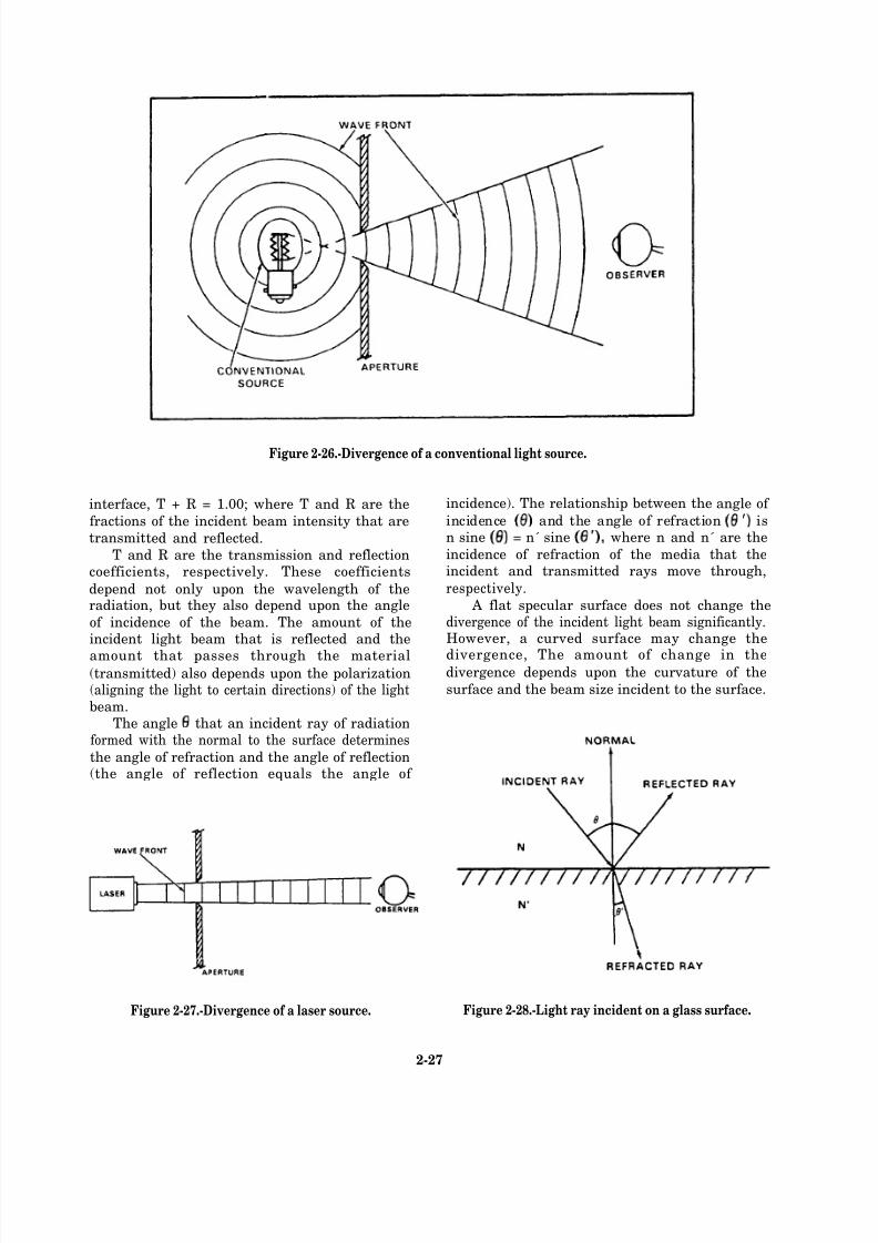
8/14/2019 US Navy Course NAVEDTRA 14028 - Aviation Electronics Technician-Basic
http://slidepdf.com/reader/full/us-navy-course-navedtra-14028-aviation-electronics-technician-basic 90/415
Figure 2-26.-Divergence of a conventional light source.
interface, T + R = 1.00; where T and R are the
fractions of the incident beam intensity that are
transmitted and reflected.
T and R are the transmission and reflectioncoefficients, respectively. These coefficients
depend not only upon the wavelength of theradiation, but they also depend upon the angle
of incidence of the beam. The amount of theincident light beam that is reflected and the
amount that passes through the material(transmitted) also depends upon the polarization(aligning the light to certain directions) of the lightbeam.
The angle that an incident ray of radiationformed with the normal to the surface determines
the angle of refraction and the angle of reflection(the angle of reflection equals the angle of
Figure 2-27.-Divergence of a laser source.
incidence). The relationship between the angle of
incidence and the angle of refraction isn sine = n´ sine where n and n´ are the
incidence of refraction of the media that theincident and transmitted rays move through,
respectively. A flat specular surface does not change the
divergence of the incident light beam significantly.However, a curved surface may change the
divergence, The amount of change in thedivergence depends upon the curvature of the
surface and the beam size incident to the surface.
Figure 2-28.-Light ray incident on a glass surface.
2-27
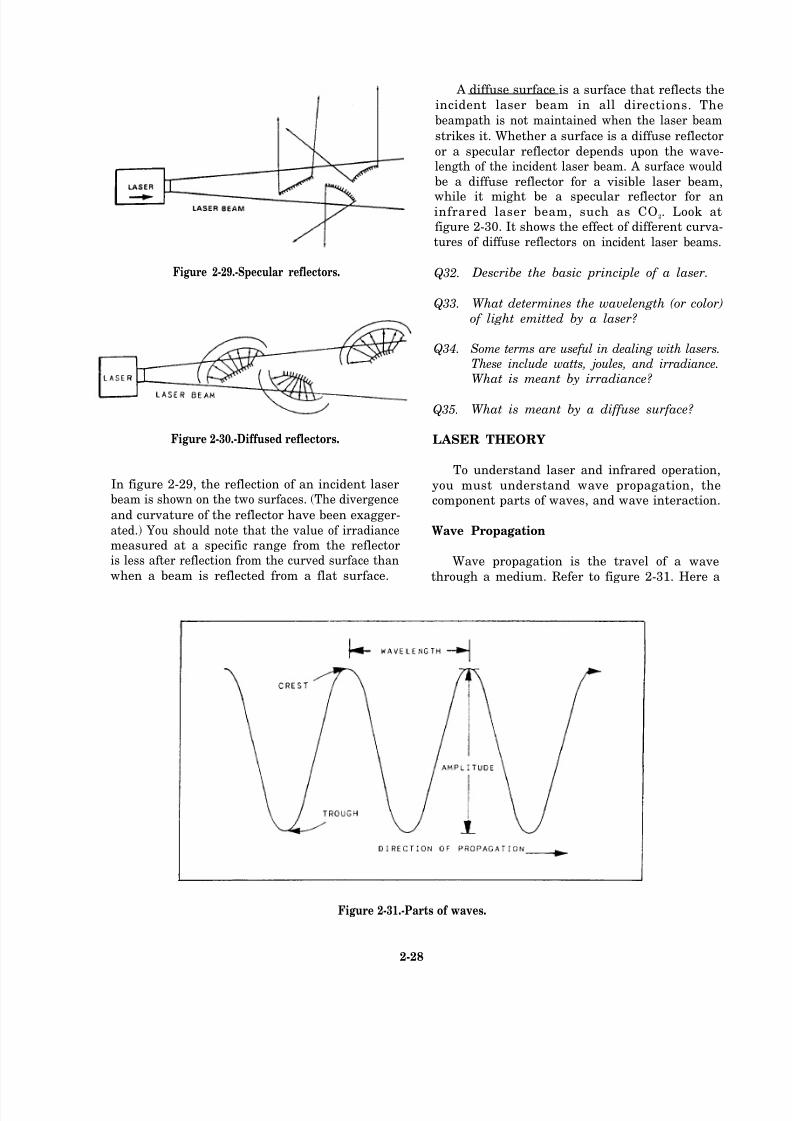
8/14/2019 US Navy Course NAVEDTRA 14028 - Aviation Electronics Technician-Basic
http://slidepdf.com/reader/full/us-navy-course-navedtra-14028-aviation-electronics-technician-basic 91/415
Figure 2-29.-Specular reflectors.
Figure 2-30.-Diffused reflectors.
In figure 2-29, the reflection of an incident laserbeam is shown on the two surfaces. (The divergence
and curvature of the reflector have been exagger-
ated.) You should note that the value of irradiancemeasured at a specific range from the reflectoris less after reflection from the curved surface than
when a beam is reflected from a flat surface.
A diffuse surface is a surface that reflects the
incident laser beam in all directions. The
beampath is not maintained when the laser beam
strikes it. Whether a surface is a diffuse reflector
or a specular reflector depends upon the wave-length of the incident laser beam. A surface would
be a diffuse reflector for a visible laser beam,
while it might be a specular reflector for aninfrared laser beam, such as CO 2. Look atfigure 2-30. It shows the effect of different curva-
tures of diffuse reflectors on incident laser beams.
Q32.
Q33.
Q34.
Q35.
Describe the basic principle of a laser.
What determines the wavelength (or color)
of light emitted by a laser?
Some terms are useful in dealing with lasers.These include watts, joules, and irradiance.What is meant by irradiance?
What is meant by a diffuse surface?
LASER THEORY
To understand laser and infrared operation,
you must understand wave propagation, thecomponent parts of waves, and wave interaction.
Wave Propagation
Wave propagation is the travel of a wave
through a medium. Refer to figure 2-31. Here a
Figure 2-31.-Parts of waves.
2-28

8/14/2019 US Navy Course NAVEDTRA 14028 - Aviation Electronics Technician-Basic
http://slidepdf.com/reader/full/us-navy-course-navedtra-14028-aviation-electronics-technician-basic 92/415
plain wave is shown, and you can see that the
propagation (direction of travel) is perpendicular
to the lines of the crest. Another type of wave is
a spherical wave that propagates outward like thatwhich a pebble causes when it is thrown into a
pond.
Wave Optics
When light strikes an object or a medium, it
is either reflected or absorbed. Wave opticsinvolve the reflection or absorption of waves.
REFLECTION.— Refer to figure 2-32. Thisfigure illustrates light reflection and refraction.
As an incident wave strikes a reflective surf ace,it is reflected from the surface. If the reflective
surface is smooth, the angle of reflection equals
the angle of incidence.
REFRACTION.— Again, refer to figure 2-32.When light passes through a transparent medium,
it is bent or refracted. The term index of refraction
refers to the amount that the light is bent or the
angle of refraction. The higher the index of refraction, the more the light is bent. The index
of refraction is a function of wavelength of the
incident light. Since different colors have differentwavelengths, they have a different index of
refraction.
DIFFUSION.— Earlier, you saw how light isreflected when it strikes a smooth surface. When
the same type of beam strikes a rough surface,
the light is scattered. The term used to describe
this scattering is diffusion. Diffusion allows you
to see nonluminous objects.
Lens Optics
Lenses are used extensively in laser and
infrared system operation. Therefore, you need
to understand lens optics before you can under-
stand the system. A lens is defined as a piece of transparent material with two opposite refracting
surfaces. Converging and diverging lenses are the
two categories of lenses. Within these categories,there are three basic types of lenses—convex,concave, and meniscus (fig. 2-33), The converginglenses are thin at the edge and thick in the middle,while the diverging lenses are thick at the edges
and thin in the middle.
Figure 2-32.-Reflection and refraction. Figure 2-33.-Types of lenses.
2-29
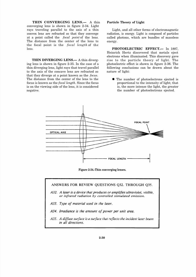
8/14/2019 US Navy Course NAVEDTRA 14028 - Aviation Electronics Technician-Basic
http://slidepdf.com/reader/full/us-navy-course-navedtra-14028-aviation-electronics-technician-basic 93/415
THIN CONVERGING LENS.— A thinconverging lens is shown in figure 2-34. Lightrays traveling parallel to the axis of a thin
convex lens are refracted so that they converge
at a point called the focal point of the lens.The distance from the center of the lens to
the focal point is the focal length of the
lens.
THIN DIVERGING LENS.— A thin diverg-
ing lens is shown in figure 2-35. In the case of a
thin diverging lens, light rays that travel parallel
to the axis of the concave lens are refracted so
that they diverge at a point known as the focus.The distance from the center of the lens to the
focus is known as the focal length. Since the focus
is on the viewing side of the lens, it is considerednegative.
Particle Theory of Light
Light, and all other forms of electromagnetic
radiation, is energy. Light is composed of particles
called photons, which are bundles of massless
energy.
PHOTOELECTRIC EFFECT.— In 1887,Heinrich Hertz discovered that metals eject
electrons when illuminated. This discovery gave
rise to the particle theory of light. Thephotoelectric effect is shown in figure 2-36. The
following conclusions can be drawn about the
nature of light:
The number of photoelectrons ejected isproportional to the intensity of light; thatis, the more intense the light, the greaterthe number of photoelectrons ejected.
Figure 2-34.-Thin converging lenses.
2-30

8/14/2019 US Navy Course NAVEDTRA 14028 - Aviation Electronics Technician-Basic
http://slidepdf.com/reader/full/us-navy-course-navedtra-14028-aviation-electronics-technician-basic 94/415
Figure 2-35.-Thin diverging lenses.
Figure 2-36.-Photoelectric effect.
2-31
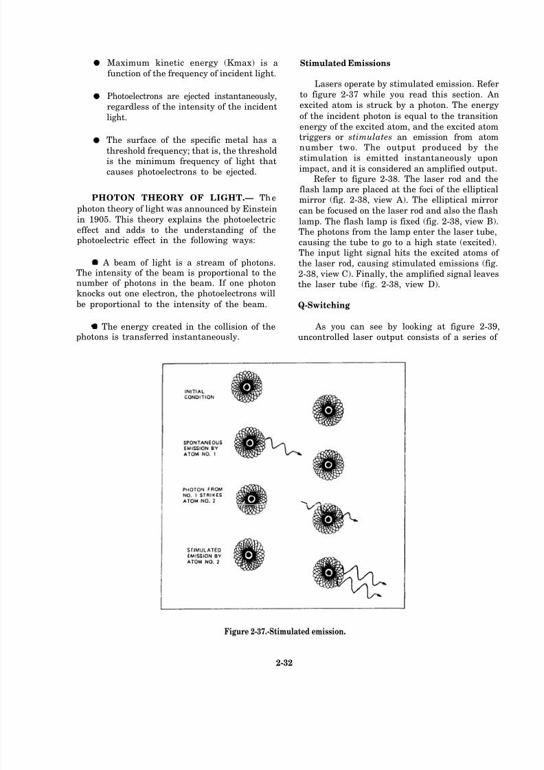
8/14/2019 US Navy Course NAVEDTRA 14028 - Aviation Electronics Technician-Basic
http://slidepdf.com/reader/full/us-navy-course-navedtra-14028-aviation-electronics-technician-basic 95/415
Maximum kinetic energy (Kmax) is a
function of the frequency of incident light.
Photoelectrons are ejected instantaneously,
regardless of the intensity of the incident
light.
The surface of the specific metal has a
threshold frequency; that is, the thresholdis the minimum frequency of light that
causes photoelectrons to be ejected.
PHOTON THEORY OF LIGHT.— The
photon theory of light was announced by Einstein
in 1905. This theory explains the photoelectric
effect and adds to the understanding of thephotoelectric effect in the following ways:
A beam of light is a stream of photons.
The intensity of the beam is proportional to thenumber of photons in the beam. If one photonknocks out one electron, the photoelectrons will
be proportional to the intensity of the beam.
The energy created in the collision of thephotons is transferred instantaneously.
Stimulated Emissions
Lasers operate by stimulated emission. Refer
to figure 2-37 while you read this section. An
excited atom is struck by a photon. The energy
of the incident photon is equal to the transition
energy of the excited atom, and the excited atom
triggers or stimulates an emission from atomnumber two. The output produced by the
stimulation is emitted instantaneously upon
impact, and it is considered an amplified output.Refer to figure 2-38. The laser rod and the
flash lamp are placed at the foci of the ellipticalmirror (fig. 2-38, view A). The elliptical mirror
can be focused on the laser rod and also the flash
lamp. The flash lamp is fixed (fig. 2-38, view B).The photons from the lamp enter the laser tube,
causing the tube to go to a high state (excited).The input light signal hits the excited atoms of
the laser rod, causing stimulated emissions (fig.
2-38, view C). Finally, the amplified signal leavesthe laser tube (fig. 2-38, view D).
Q-Switching
As you can see by looking at figure 2-39,
uncontrolled laser output consists of a series of
Figure 2-37.-Stimulated emission.
2-32
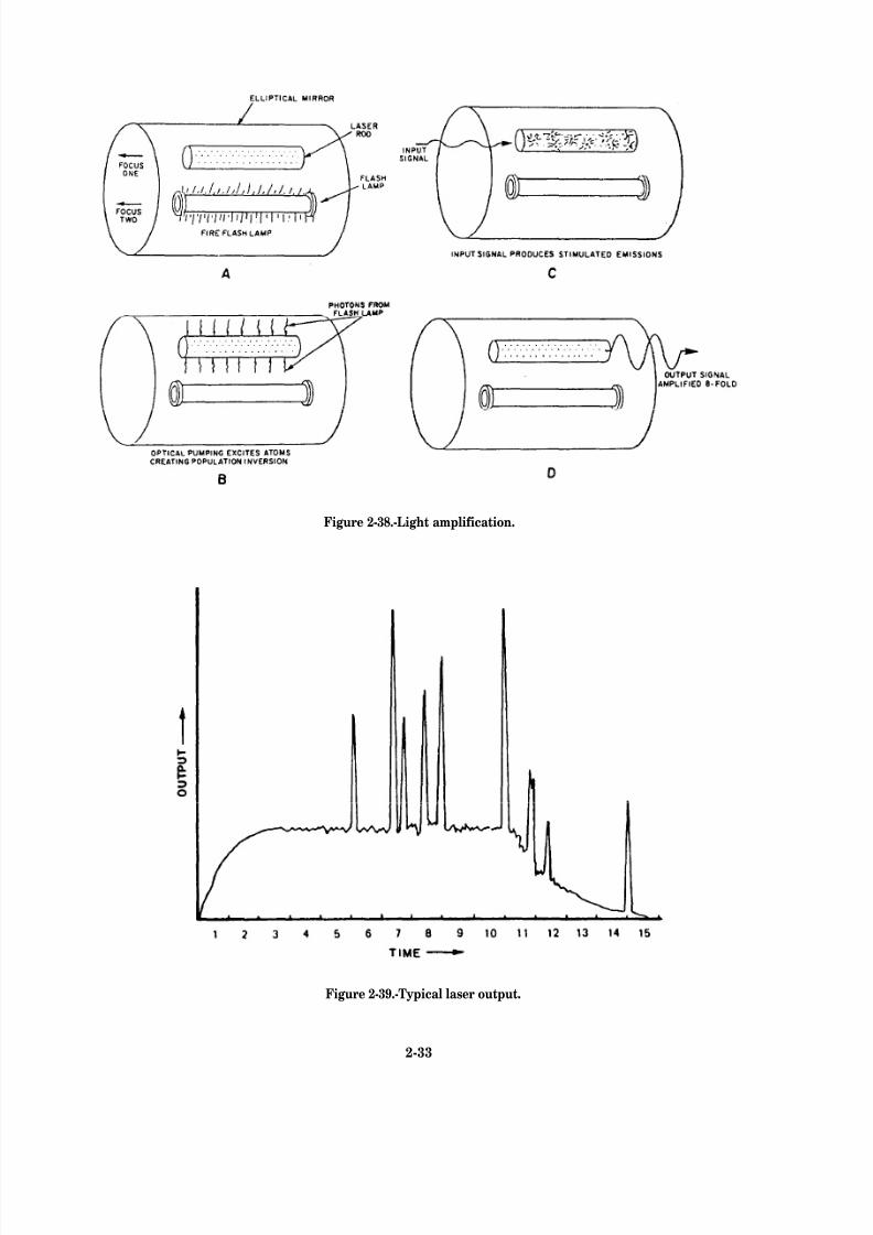
8/14/2019 US Navy Course NAVEDTRA 14028 - Aviation Electronics Technician-Basic
http://slidepdf.com/reader/full/us-navy-course-navedtra-14028-aviation-electronics-technician-basic 96/415
Figure 2-38.-Light amplification.
Figure 2-39.-Typical laser output.
2-33

8/14/2019 US Navy Course NAVEDTRA 14028 - Aviation Electronics Technician-Basic
http://slidepdf.com/reader/full/us-navy-course-navedtra-14028-aviation-electronics-technician-basic 97/415
Figure 2-40.-—Pockels cell.
Figure 2-41.-Laser pulse comparison.
2-34
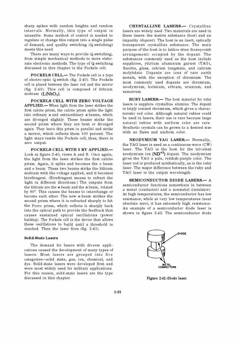
8/14/2019 US Navy Course NAVEDTRA 14028 - Aviation Electronics Technician-Basic
http://slidepdf.com/reader/full/us-navy-course-navedtra-14028-aviation-electronics-technician-basic 98/415
8/14/2019 US Navy Course NAVEDTRA 14028 - Aviation Electronics Technician-Basic
http://slidepdf.com/reader/full/us-navy-course-navedtra-14028-aviation-electronics-technician-basic 99/415
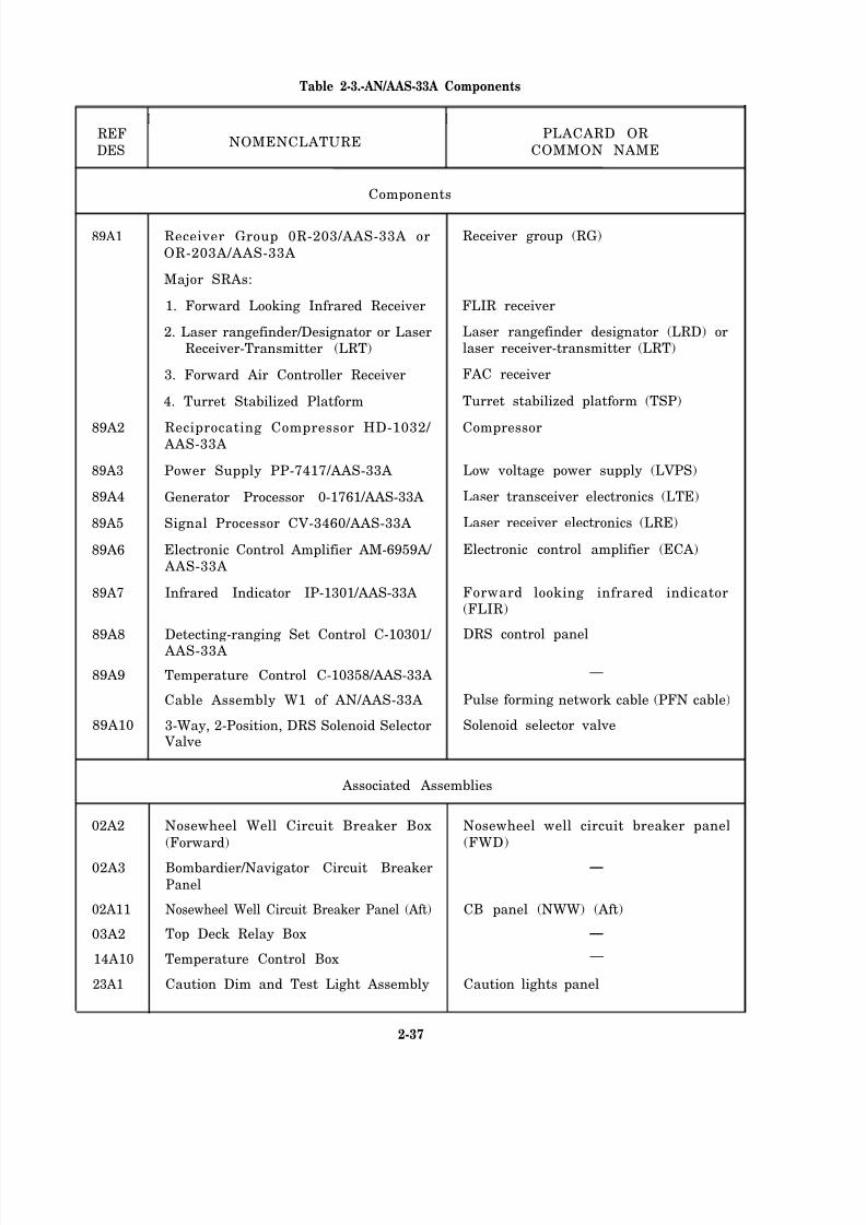
8/14/2019 US Navy Course NAVEDTRA 14028 - Aviation Electronics Technician-Basic
http://slidepdf.com/reader/full/us-navy-course-navedtra-14028-aviation-electronics-technician-basic 100/415
Table 2-3.-AN/AAS-33A Components
I I
REFNOMENCLATURE
PLACARD OR
DES COMMON NAME
Components
89A1
89A2
89A3
89A4
89A5
89A6
89A7
89A8
89A9
89A10
02A2
02A3
02A11
03A2
14A10
23A1
Receiver Group 0R-203/AAS-33A or
OR-203A/AAS-33A
Major SRAs:
1. Forward Looking Infrared Receiver
2. Laser rangefinder/Designator or LaserReceiver-Transmitter (LRT)
3. Forward Air Controller Receiver
4. Turret Stabilized Platform
Reciprocating Compressor HD-1032/ AAS-33A
Power Supply PP-7417/AAS-33A
Generator Processor 0-1761/AAS-33A
Signal Processor CV-3460/AAS-33A
Electronic Control Amplifier AM-6959A/
AAS-33A
Infrared Indicator IP-1301/AAS-33A
Detecting-ranging Set Control C-10301/ AAS-33A
Temperature Control C-10358/AAS-33A
Cable Assembly W1 of AN/AAS-33A
3-Way, 2-Position, DRS Solenoid Selector Valve
Receiver group (RG)
FLIR receiver
Laser rangefinder designator (LRD) orlaser receiver-transmitter (LRT)
FAC receiver
Turret stabilized platform (TSP)
Compressor
Low voltage power supply (LVPS)
Laser transceiver electronics (LTE)
Laser receiver electronics (LRE)
Electronic control amplifier (ECA)
Forward looking infrared indicator(FLIR)
DRS control panel
—
Pulse forming network cable (PFN cable)
Solenoid selector valve
Associated Assemblies
Nosewheel Well Circuit Breaker Box
(Forward)
Bombardier/Navigator Circuit Breaker
Panel
Nosewheel Well Circuit Breaker Panel (Aft)
Top Deck Relay Box
Temperature Control Box
Caution Dim and Test Light Assembly
Nosewheel well circuit breaker panel
(FWD)
CB panel (NWW) (Aft)
—
Caution lights panel
2-37
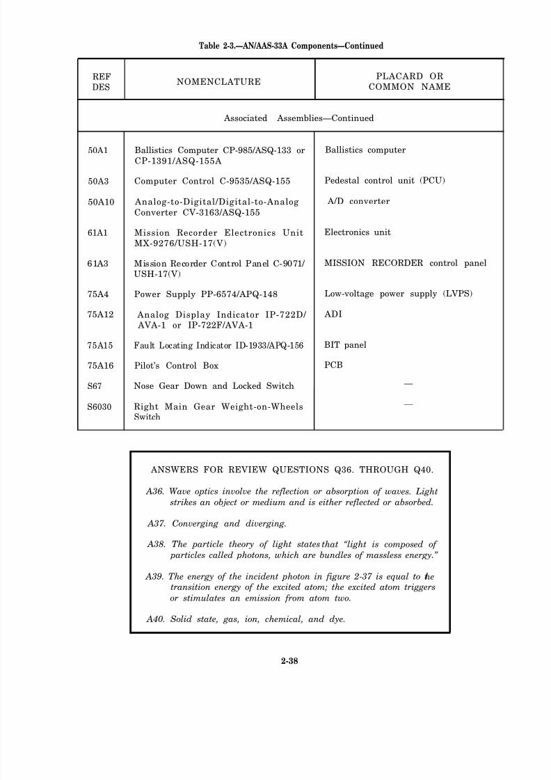
8/14/2019 US Navy Course NAVEDTRA 14028 - Aviation Electronics Technician-Basic
http://slidepdf.com/reader/full/us-navy-course-navedtra-14028-aviation-electronics-technician-basic 101/415
Table 2-3.—AN/AAS-33A Components—Continued
REFNOMENCLATURE
PLACARD OR
DES COMMON NAME
Associated Assemblies—Continued
50A1 Ballistics Computer CP-985/ASQ-133 or Ballistics computer
CP-1391/ASQ-155A
50A3 Computer Control C-9535/ASQ-155 Pedestal control unit (PCU)
50A10 Analog-to-Digital/Digital-to-Analog A/D converter
Converter CV-3163/ASQ-155
61A1 Mission Recorder Electronics Unit Electronics unit
MX-9276/USH-17(V)
61A3 Mission Recorder Control Panel C-9071/ MISSION RECORDER control panel
USH-17(V)
75A4 Power Supply PP-6574/APQ-148 Low-voltage power supply (LVPS)
75A12 Analog Display Indicator IP-722D/ ADI
AVA-1 or IP-722F/AVA-1
75A15 Fault Locating Indicator ID-1933/APQ-156 BIT panel
75A16 Pilot’s Control Box PCB
S67 Nose Gear Down and Locked Switch —
S6030 Right Main Gear Weight-on-Wheels—
Switch
ANSWERS FOR REVIEW QUESTIONS Q36. THROUGH Q40.
A36. Wave optics involve the reflection or absorption of wav es. Light
strikes an object or medium and is either reflected or absorbed.
A37. Converging and diverging.
A38. The particle theory of light states that “light is composed of particles called photons, which are bundles of massless energy.”
A39. The energy of the incident photon in figure 2-37 is equal to thetransition energy of the excited atom; the excited atom triggers
or stimulates an emission from atom two.
A40. Solid state, gas, ion, chemical, and dye.
2-38
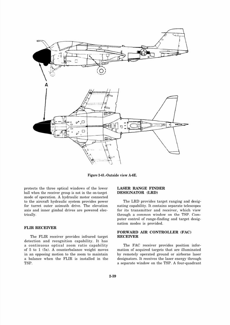
8/14/2019 US Navy Course NAVEDTRA 14028 - Aviation Electronics Technician-Basic
http://slidepdf.com/reader/full/us-navy-course-navedtra-14028-aviation-electronics-technician-basic 102/415
Figure 2-43 .-Outside view A-6E.
protects the three optical windows of the lower
ball when the receiver group is not in the on-targetmode of operation. A hydraulic motor connectedto the aircraft hydraulic system provides powerfor turret outer azimuth drive. The elevation
axis and inner gimbal drives are powered elec-
trically.
FLIR RECEIVER
The FLIR receiver provides infrared target
detection and recognition capability. It hasa continuous optical zoom ratio capabilityof 5 to 1 (5x). A counterbalance weight moves
in an opposing motion to the zoom to maintain
a balance when the FLIR is installed in the
TSP.
LASER RANGE FINDERDESIGNATOR (LRD)
The LRD provides target ranging and desig-
nating capability. It contains separate telescopes
for its transmitter and receiver, which view
through a common window on the TSP. Com-puter control of range-finding and target desig-
nation modes is provided.
FORWARD AIR CONTROLLER (FAC)RECEIVER
The FAC receiver provides position infor-
mation of acquired targets that are illuminated
by remotely operated ground or airborne laser
designators. It receives the laser energy through
a separate window on the TSP. A four-quadrant
2-39
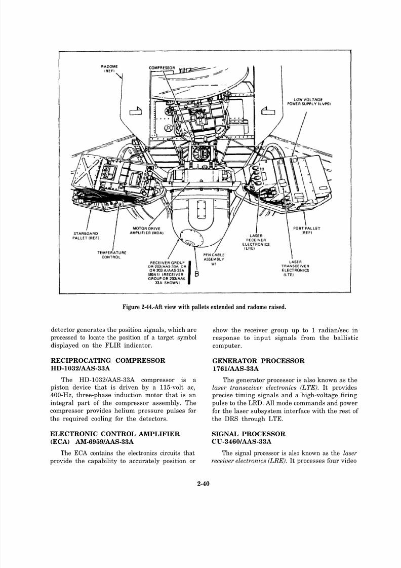
8/14/2019 US Navy Course NAVEDTRA 14028 - Aviation Electronics Technician-Basic
http://slidepdf.com/reader/full/us-navy-course-navedtra-14028-aviation-electronics-technician-basic 103/415
Figure 2-44.-Aft view with pallets extended and radome raised.
detector generates the position signals, which are
processed to locate the position of a target symbol
displayed on the FLIR indicator.
RECIPROCATING COMPRESSOR
HD-1032/AAS-33A
The HD-1032/AAS-33A compressor is apiston device that is driven by a 115-volt ac,
400-Hz, three-phase induction motor that is anintegral part of the compressor assembly. The
compressor provides helium pressure pulses for
the required cooling for the detectors.
ELECTRONIC CONTROL AMPLIFIER
(ECA) AM-6959/AAS-33A
The ECA contains the electronics circuits that
provide the capability to accurately position or
show the receiver group up to 1 radian/sec inresponse to input signals from the ballistic
computer.
GENERATOR PROCESSOR
1761/AAS-33A
The generator processor is also known as thelaser transceiver electronics (LTE). It provides
precise timing signals and a high-voltage firingpulse to the LRD. All mode commands and power
for the laser subsystem interface with the rest of
the DRS through LTE.
SIGNAL PROCESSORCU-3460/AAS-33A
The signal processor is also known as the laserreceiver electronics (LRE). It processes four video
2-40
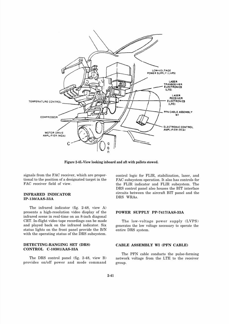
8/14/2019 US Navy Course NAVEDTRA 14028 - Aviation Electronics Technician-Basic
http://slidepdf.com/reader/full/us-navy-course-navedtra-14028-aviation-electronics-technician-basic 104/415
Figure 2-45.-View looking inboard and aft with pallets stowed.
signals from the FAC receiver, which are propor-tional to the position of a designated target in theFAC receiver field of view.
INFRARED INDICATOR
IP-130/AAS-33A
The infrared indicator (fig. 2-48, view A)
presents a high-resolution video display of the
infrared scene in real-time on an 8-inch diagonalCRT. In-flight video tape recordings can be madeand played back on the infrared indicator. Six
status lights on the front panel provide the B/Nwith the operating status of the DRS subsystem.
DETECTING-RANGING SET (DRS)
CONTROL C-10301/AAS-33A
The DRS control panel (fig. 2-48, view B)
provides on/off power and mode command
control logic for FLIR, stabilization, laser, andFAC subsystem operation. It also has controls for
the FLIR indicator and FLIR subsystem. TheDRS control panel also houses the BIT interface
circuits between the aircraft BIT panel and theDRS WRAs.
POWER SUPPLY PP-7417/AAS-33A
The low-voltage power supply (LVPS)
generates the low voltage necessary to operate theentire DRS system.
CABLE ASSEMBLY WI (PFN CABLE)
The PFN cable conducts the pulse-formingnetwork voltage from the LTE to the receiver
group.
2-41
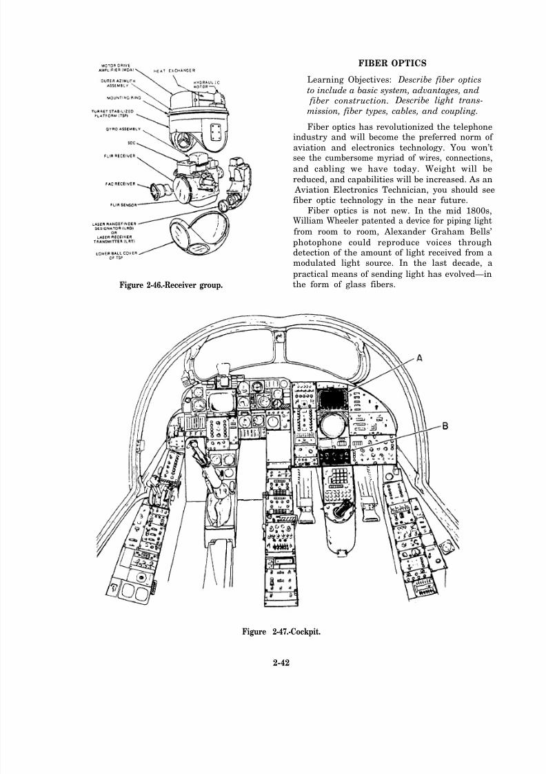
8/14/2019 US Navy Course NAVEDTRA 14028 - Aviation Electronics Technician-Basic
http://slidepdf.com/reader/full/us-navy-course-navedtra-14028-aviation-electronics-technician-basic 105/415
FIBER OPTICS
Learning Objectives: Describe fiber optics
to include a basic system, advantages, and fiber construction. Describe light trans-
mission, fiber types, cables, and coupling.
Fiber optics has revolutionized the telephone
industry and will become the preferred norm of aviation and electronics technology. You won’tsee the cumbersome myriad of wires, connections,
and cabling we have today. Weight will be
reduced, and capabilities will be increased. As an Aviation Electronics Technician, you should seefiber optic technology in the near future.
Fiber optics is not new. In the mid 1800s,William Wheeler patented a device for piping light
from room to room, Alexander Graham Bells’
photophone could reproduce voices throughdetection of the amount of light received from amodulated light source. In the last decade, a
practical means of sending light has evolved—inFigure 2-46.-Receiver group. the form of glass fibers.
Figure 2-47.-Cockpit.
2-42

8/14/2019 US Navy Course NAVEDTRA 14028 - Aviation Electronics Technician-Basic
http://slidepdf.com/reader/full/us-navy-course-navedtra-14028-aviation-electronics-technician-basic 106/415
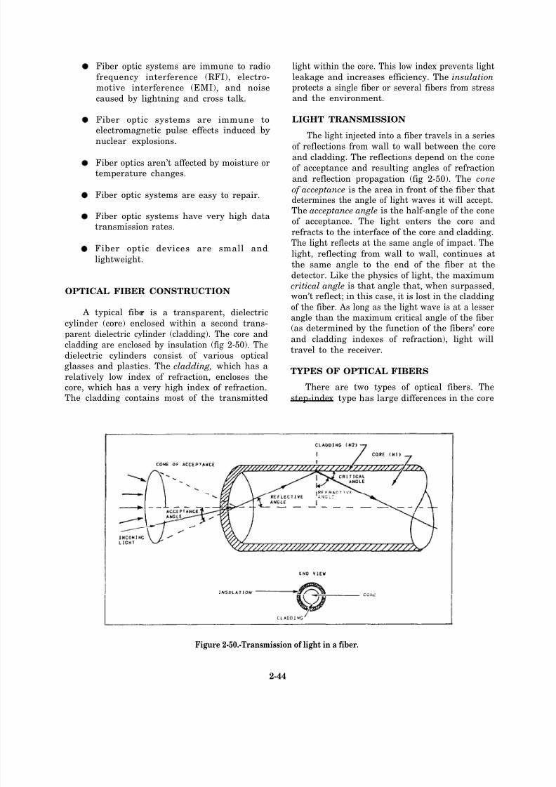
8/14/2019 US Navy Course NAVEDTRA 14028 - Aviation Electronics Technician-Basic
http://slidepdf.com/reader/full/us-navy-course-navedtra-14028-aviation-electronics-technician-basic 107/415
Fiber optic systems are immune to radio
frequency interference (RFI), electro-
motive interference (EMI), and noise
caused by lightning and cross talk.
Fiber optic systems are immune toelectromagnetic pulse effects induced by
nuclear explosions.
Fiber optics aren’t affected by moisture ortemperature changes.
Fiber optic systems are easy to repair.
Fiber optic systems have very high datatransmission rates.
Fiber optic devices are small and
lightweight.
OPTICAL FIBER CONSTRUCTION
A typical fiber is a transparent, dielectric
cylinder (core) enclosed within a second trans-
parent dielectric cylinder (cladding). The core and
cladding are enclosed by insulation (fig 2-50). The
dielectric cylinders consist of various opticalglasses and plastics. The cladding, which has a
relatively low index of refraction, encloses thecore, which has a very high index of refraction.The cladding contains most of the transmitted
light within the core. This low index prevents light
leakage and increases efficiency. The insulationprotects a single fiber or several fibers from stressand the environment.
LIGHT TRANSMISSION
The light injected into a fiber travels in a seriesof reflections from wall to wall between the core
and cladding. The reflections depend on the cone
of acceptance and resulting angles of refraction
and reflection propagation (fig 2-50). The cone
of acceptance is the area in front of the fiber thatdetermines the angle of light waves it will accept.The acceptance angle is the half-angle of the cone
of acceptance. The light enters the core and
refracts to the interface of the core and cladding.The light reflects at the same angle of impact. The
light, reflecting from wall to wall, continues at
the same angle to the end of the fiber at the
detector. Like the physics of light, the maximumcritical angle is that angle that, when surpassed,won’t reflect; in this case, it is lost in the cladding
of the fiber. As long as the light wave is at a lesserangle than the maximum critical angle of the fiber(as determined by the function of the fibers’ core
and cladding indexes of refraction), light will
travel to the receiver.
TYPES OF OPTICAL FIBERS
There are two types of optical fibers. The
step-index type has large differences in the core
Figure 2-50.-Transmission of light in a fiber.
2-44

8/14/2019 US Navy Course NAVEDTRA 14028 - Aviation Electronics Technician-Basic
http://slidepdf.com/reader/full/us-navy-course-navedtra-14028-aviation-electronics-technician-basic 108/415
and cladding indexes of refraction. When heldconstant, these differences cause light to reflect
from the interface back through the core to its
opposite wall.
The graded-index type has a decreasing core
refractive index as the radial distance from the
core increases. This causes the light rays to
continuously refocus as they travel down the fiber.These types operate in either single-mode or multi-
mode operation. Single-mode operation accepts
a specific wavelength, otherwise large attenuationwill result. The multi-mode type operates over a
range of wavelengths with minimum signal loss.
(See fig. 2-51.)
PROPERTIES OF OPTICAL CABLES
Optical cables are affected by many physicalproperties, Some of these are discussed in the
following section.
Numerical Index
The numerical index of optical cables dealswith the sine of the angle of acceptance. The
numerical aperature (NA) or numerical index can
be found using the formula shown below:
where i = acceptance angle, n1 = Core Index of
Refract ion , and n2 = Cladding Index of Refraction.
The acceptance angle is a measure of thenumerical aperature (NA) or numerical indexof a fiber. This lets the manufacturer select
the proper fiber for the desired specific light
waves and for optimum power coupling. NA
is a measure of the light capture angle (half-
acceptance angle). It describes the max core angle
of light rays that will be reflected down the fiberby total reflection.
The refractive index (Index of Refraction) of
a material is the ratio of the speed of light in a vacuum to the speed of light in the material.
Review chapter 1 for more information on
refraction if you don’t understand this section.
The higher the refractive index of a material, the
lower the velocity of light through the material.
Also, there will be more refraction or bending of
the light when it enters the material.If NA increases, angle i must have increased,
and the fiber sees more light. NA can never be
greater than 1.0; normal values are low (0.2 and0.6).
Dispersion
Dispersion is the spreading or widening of light
waves due to the refractive index of the material
and the wavelength of the light traveling in thefiber. There are two types of dispersion—
intermodal and intramodal.
Intermodal (multi-mode) dispersion. Inter-
modal dispersion is the propagation (travel) of
rays of the same wavelength along different paths
through the fiber. These wavelength rays arriveat the receiving end at different times.
Figure 2-51.-Types of optical fibers.
2-45
8/14/2019 US Navy Course NAVEDTRA 14028 - Aviation Electronics Technician-Basic
http://slidepdf.com/reader/full/us-navy-course-navedtra-14028-aviation-electronics-technician-basic 109/415
Intramodal dispersion.
is due to variations of the
the core and cladding.
Attenuation
Intramodal dispersion
index of refraction of
Attenuation is the loss or reduction inamplitude of the energy transmitted. These lossesare due to differences of refractive indexes andimperfections in fiber materials. Also, man-made
scratches or dirt and light scattering within the
fiber cause unwanted losses. Efforts to reducethese losses include the forming of the followingstandard parameters:
Bandwidth parameters. Bandwidth param-
eters include attenuation curves, whichprovide all designers the ability to chose
the best fiber. These parameters are plottedin decibels per kilometer (dB/km). Theymeasure the efficiency of the fiber as a
comparison of light transmission to lightloss through a fiber.
Rise time parameters. These parameters set
speed requirements for operation.
Fiber strength parameters. These
parameters set tensile strength standardsto help reduce flaws and microcracks in thefiber.
FIBER COUPLING
One important aspect of a fiber system is the
connection between the fiber and the other parts.The coupling efficiency is the ratio of power
accepted by the fiber to the power emitted by thesource
Coupling efficiency increases with the square of the NA (numerical aperature) and decreases withsource and fiber mismatches. Optical powercoupled into the fiber is a function of the radianceof the source and the NA.
Q41.
Q42.
Q43.
Q44.
Q45.
A basic fiber optic system consists of a
transmitter, a fiber medium, and a receiver. Describe the basic technique of fiber optics.
List the advantages of fiber optic systems.
By what means does light travel through a
fiber optic?
What is the difference between single-mode
and multi-mode operation?
Attenuation is the loss or reduction of energy transmitted. Efforts to reduce theselosses include the forming of standard
parameters. What are these parameters?
2-46

8/14/2019 US Navy Course NAVEDTRA 14028 - Aviation Electronics Technician-Basic
http://slidepdf.com/reader/full/us-navy-course-navedtra-14028-aviation-electronics-technician-basic 110/415
(THIS PAGE IS INTENTIONALLY LEFT BLANK.)
2-47

8/14/2019 US Navy Course NAVEDTRA 14028 - Aviation Electronics Technician-Basic
http://slidepdf.com/reader/full/us-navy-course-navedtra-14028-aviation-electronics-technician-basic 111/415
ANSWERS FOR REVIEW QUESTIONS Q41. THROUGH Q45.
A41. Fiber optics is the technique of sending data, in the form of light,
through long, thin, flexible fibers of glass, plastic, or other
transparent materials.
A42. (a) Usable in flammable areas
(b) Immune to noises generated by RFI, EMI, lightning, and
cross talk
(c) Immune to electromagnetic pulse effects
(d) Not a ffected by moisture or temperature changes
(e) Easy to repair
(f) Very high transmission rates
(g) Small size and lightweight
A43. The light injected into a fiber travels in a series of reflections
from wall to wall between core and cladding. The reflectionsdepend on the cone of acceptance and resulting angles of
refraction and reflection propagation.
A44. Single-mode types accept a specific wavelength, otherwise, large
attenuation results. Multi-mode types operate over a range of wavelengths, with minimum signal loss.
A45. (a) Bandwidth parameters provide designers the ability to choosethe best fiber.
(b) Rise time parameters set the spe ed requirements for fiber
operation.
(c) Fiber strength parameters set tensile strength requirementsto help reduce flaws and microcracks in the fiber.
2-48
8/14/2019 US Navy Course NAVEDTRA 14028 - Aviation Electronics Technician-Basic
http://slidepdf.com/reader/full/us-navy-course-navedtra-14028-aviation-electronics-technician-basic 112/415
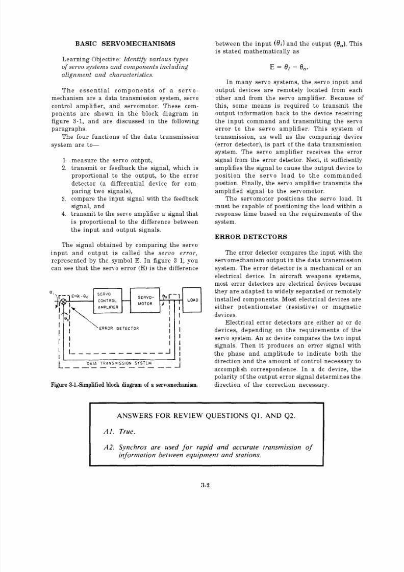
8/14/2019 US Navy Course NAVEDTRA 14028 - Aviation Electronics Technician-Basic
http://slidepdf.com/reader/full/us-navy-course-navedtra-14028-aviation-electronics-technician-basic 113/415

8/14/2019 US Navy Course NAVEDTRA 14028 - Aviation Electronics Technician-Basic
http://slidepdf.com/reader/full/us-navy-course-navedtra-14028-aviation-electronics-technician-basic 114/415
Error detectors are used in gyrostabilizedplatforms and rate gyros. In stabilized platforms,
synchros are attached to gimbals. Any movementof the platform around the gyro axes is detectedby the synchro, and the error voltage is sent tothe appropriate servo system.
In rate gyros, an E-transformer is used todetect gyro precession. The E-transformer is
sensitive to slight changes, but its movement islimited to a small amount. It is used with
constrained gyros.
POTENTIOMETER
Potentiometer error detector systems are usedwhere the input and output of the servo-
mechanism have limited motion. These systems
have the following advantages:
High accuracy.
Small size.
Either a dc or an ac voltage may beobtained as the output.
Disadvantages of potentiometer error detectorsystems include the following:
Limited motion.
A life problem that results from wear of the brush on the potentiometer wire.
A
The potentiometer voltage output changes
in discrete steps as the brush moves fromwire to wire.
Some potentiometers require a high drive
torque to rotate the wiper contact.
balanced potentiometer error detector isshown in figure 3-2. The purpose of this circuit
is to give an output error voltage proportional to
the difference between the input and outputsignals. In the following paragraphs, you willlearn how the potentiometer error detector works.Refer to figure 3-2 as you read the following
paragraphs.
The command input shaft is mechanicallylinked to R1, and the load is mechanically linked
to R2. An electrical source of 115 volts ac is
applied across both potentiometers.When the input and output shafts are in the
same angular position, they are in corre-spondence, and there is no output error voltage.If the input shaft is rotated, the wiper contact of R1 is moved. This action causes an error voltage
to be developed and applied to the control
amplifier. The error voltage is the difference of
the voltages at the wiper contacts of R1 and R2.The amplifier output causes the motor to rotate
both the load and the wiper contact of R2 until
both voltages are equal. When this occurs, there
is no output error voltage.In figure 3-2, both R1 and R2 are shown
grouped together. In actual practice, the
potentiometers may be remotely located fromeach other. R2, the output potentiometer, may
be located at the output shaft or load. The remotelocation of one of the components does not
remove it as part of the error detector.
Figure 3-2.-Balanced potentiometer error detector system.
3-3
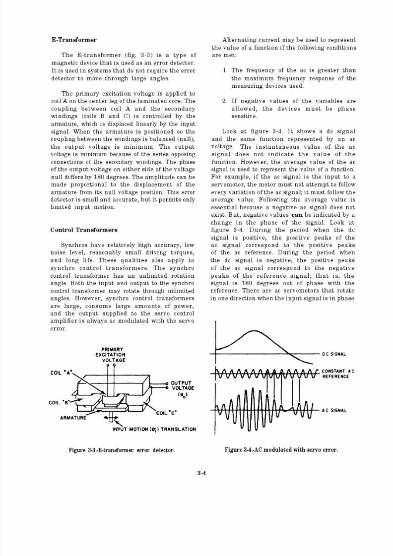
8/14/2019 US Navy Course NAVEDTRA 14028 - Aviation Electronics Technician-Basic
http://slidepdf.com/reader/full/us-navy-course-navedtra-14028-aviation-electronics-technician-basic 115/415
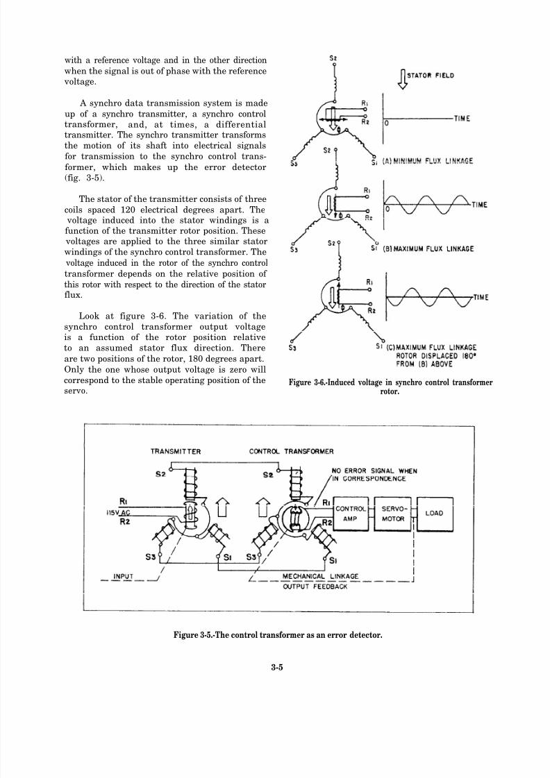
8/14/2019 US Navy Course NAVEDTRA 14028 - Aviation Electronics Technician-Basic
http://slidepdf.com/reader/full/us-navy-course-navedtra-14028-aviation-electronics-technician-basic 116/415
with a reference voltage and in the other direction
when the signal is out of phase with the reference voltage.
A synchro data transmission system is made
up of a synchro transmitter, a synchro controltransformer, and, at times, a differential
transmitter. The synchro transmitter transformsthe motion of its shaft into electrical signals
for transmission to the synchro control trans-
former, which makes up the error detector
(fig. 3-5).
The stator of the transmitter consists of three
coils spaced 120 electrical degrees apart. The voltage induced into the stator windings is afunction of the transmitter rotor position. These
voltages are applied to the three similar stator
windings of the synchro control transformer. The
voltage induced in the rotor of the synchro control
transformer depends on the relative position of this rotor with respect to the direction of the statorflux.
Look at figure 3-6. The variation of the
synchro control transformer output voltageis a function of the rotor position relative
to an assumed stator flux direction. There
are two positions of the rotor, 180 degrees apart.
Only the one whose output voltage is zero will
correspond to the stable operating position of theservo.
Figure 3-6.-Induced voltage in synchro control transformerrotor.
Figure 3-5.-The control transformer as an error detector.
3-5
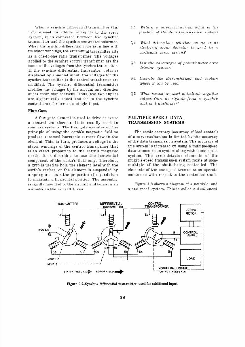
8/14/2019 US Navy Course NAVEDTRA 14028 - Aviation Electronics Technician-Basic
http://slidepdf.com/reader/full/us-navy-course-navedtra-14028-aviation-electronics-technician-basic 117/415
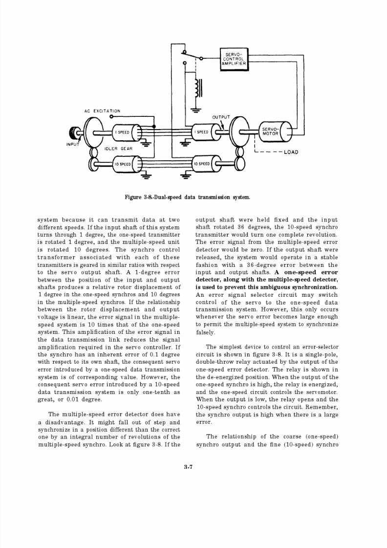
8/14/2019 US Navy Course NAVEDTRA 14028 - Aviation Electronics Technician-Basic
http://slidepdf.com/reader/full/us-navy-course-navedtra-14028-aviation-electronics-technician-basic 118/415
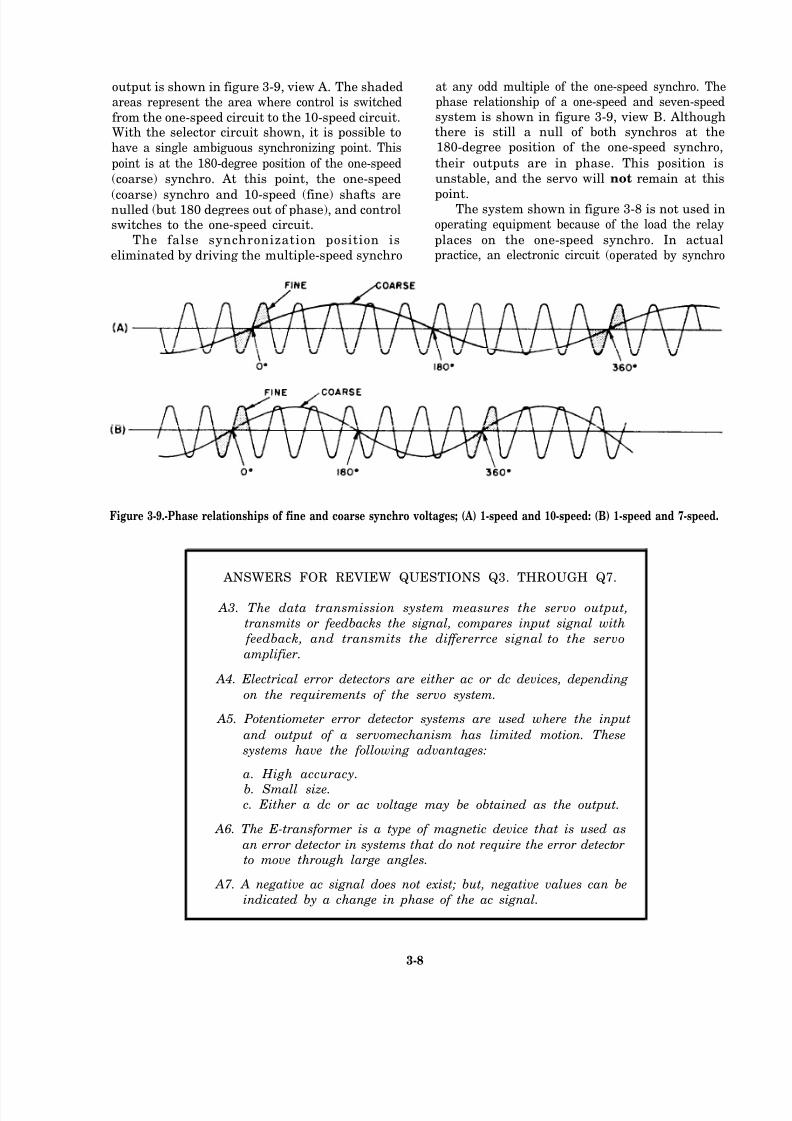
8/14/2019 US Navy Course NAVEDTRA 14028 - Aviation Electronics Technician-Basic
http://slidepdf.com/reader/full/us-navy-course-navedtra-14028-aviation-electronics-technician-basic 119/415
output is shown in figure 3-9, view A. The shadedareas represent the area where control is switched
from the one-speed circuit to the 10-speed circuit.With the selector circuit shown, it is possible to
have a single ambiguous synchronizing point. This
point is at the 180-degree position of the one-speed
(coarse) synchro. At this point, the one-speed
(coarse) synchro and 10-speed (fine) shafts arenulled (but 180 degrees out of phase), and controlswitches to the one-speed circuit.
The false synchronization position is
eliminated by driving the multiple-speed synchro
at any odd multiple of the one-speed synchro. Thephase relationship of a one-speed and seven-speedsystem is shown in figure 3-9, view B. Althoughthere is still a null of both synchros at the180-degree position of the one-speed synchro,
their outputs are in phase. This position is
unstable, and the servo will not remain at this
point.The system shown in figure 3-8 is not used in
operating equipment because of the load the relay
places on the one-speed synchro. In actualpractice, an electronic circuit (operated by synchro
Figure 3-9.-Phase relationships of fine and coarse synchro voltages; (A) 1-speed and 10-speed: (B) 1-speed and 7-speed.
ANSWERS FOR REVIEW QUESTIONS Q3. THROUGH Q7.
A3. The data transmission system measures the servo output,
transmits or feedbacks the signal, compares input signal with
feedback, and transmits the dif fererrce signal to the servo
amplifier.
A4. Electrical error detectors are either ac or dc devices, depending
on the requirements of the servo system.
A5. Potentiometer error detector systems are used where the input
and output of a servomechanism has limited motion. These
systems have the following advantages:
a. High accuracy.
b. Small size.c. Either a dc or ac voltage may be obtained as the output.
A6. The E-transformer is a type of magnetic device that is used as
an error detector in systems that do not require the error detector
to move through large angles.
A7. A negative ac signal does not exist; but, negative values can be
indicated by a change in phase of the ac signal.
3-8

8/14/2019 US Navy Course NAVEDTRA 14028 - Aviation Electronics Technician-Basic
http://slidepdf.com/reader/full/us-navy-course-navedtra-14028-aviation-electronics-technician-basic 120/415
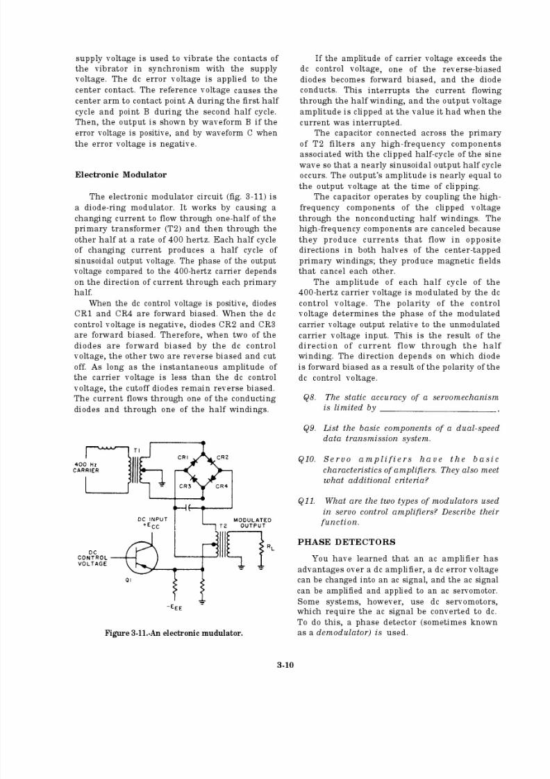
8/14/2019 US Navy Course NAVEDTRA 14028 - Aviation Electronics Technician-Basic
http://slidepdf.com/reader/full/us-navy-course-navedtra-14028-aviation-electronics-technician-basic 121/415
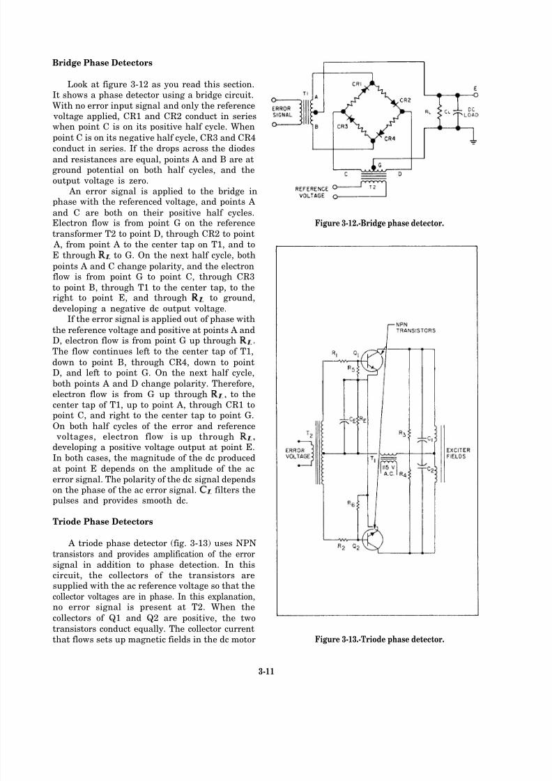
8/14/2019 US Navy Course NAVEDTRA 14028 - Aviation Electronics Technician-Basic
http://slidepdf.com/reader/full/us-navy-course-navedtra-14028-aviation-electronics-technician-basic 122/415
Bridge Phase Detectors
Look at figure 3-12 as you read this section.It shows a phase detector using a bridge circuit.
With no error input signal and only the reference voltage applied, CR1 and CR2 conduct in serieswhen point C is on its positive half cycle. When
point C is on its negative half cycle, CR3 and CR4conduct in series. If the drops across the diodes
and resistances are equal, points A and B are atground potential on both half cycles, and the
output voltage is zero. An error signal is applied to the bridge in
phase with the referenced voltage, and points A
and C are both on their positive half cycles.Electron flow is from point G on the reference
transformer T2 to point D, through CR2 to point
A, from point A to the center tap on T1, and to
E through to G. On the next half cycle, both
points A and C change polarity, and the electron
flow is from point G to point C, through CR3to point B, through T1 to the center tap, to theright to point E, and through to ground,
developing a negative dc output voltage.If the error signal is applied out of phase with
the reference voltage and positive at points A andD, electron flow is from point G up through
The flow continues left to the center tap of T1,
down to point B, through CR4, down to pointD, and left to point G. On the next half cycle,
both points A and D change polarity. Therefore,
electron flow is from G up through to thecenter tap of T1, up to point A, through CR1 topoint C, and right to the center tap to point G.
On both half cycles of the error and reference voltages, electron flow is up throughdeveloping a positive voltage output at point E.
In both cases, the magnitude of the dc produced
at point E depends on the amplitude of the ac
error signal. The polarity of the dc signal dependson the phase of the ac error signal. filters thepulses and provides smooth dc.
Triode Phase Detectors
A triode phase detector (fig. 3-13) uses NPNtransistors and provides amplification of the error
signal in addition to phase detection. In thiscircuit, the collectors of the transistors aresupplied with the ac reference voltage so that the
collector voltages are in phase. In this explanation,no error signal is present at T2. When the
collectors of Q1 and Q2 are positive, the two
transistors conduct equally. The collector current
that flows sets up magnetic fields in the dc motor
Figure 3-12.-Bridge phase detector.
Figure 3-13.-Triode phase detector.
3-11

8/14/2019 US Navy Course NAVEDTRA 14028 - Aviation Electronics Technician-Basic
http://slidepdf.com/reader/full/us-navy-course-navedtra-14028-aviation-electronics-technician-basic 123/415
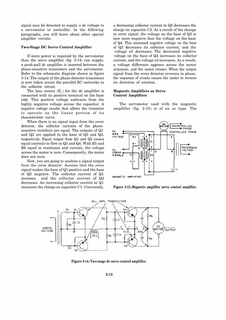
8/14/2019 US Navy Course NAVEDTRA 14028 - Aviation Electronics Technician-Basic
http://slidepdf.com/reader/full/us-navy-course-navedtra-14028-aviation-electronics-technician-basic 124/415
signal may be detected to supply a dc voltage to
a servomotor or controller. In the following
paragraphs, you will learn about other specialamplif ier circuits.
Two-Stage DC Servo Control Amplifier
If more power is required by the servomotorthan the servo amplifier (fig. 3-14) can supply,
a push-pull dc amplifier is inserted between the
phase-sensitive transistors and the servomotor.
Refer to the schematic diagram shown in figure
3-14. The output of the phase detector transistorsis now taken across the parallel RC networks inthe collector circuit.
The bias source (Ecc) for the dc amplifier is
connected with its positive terminal on the baseside. This positive voltage subtracts from the
highly negative voltage across the capacitor. A
negative voltage results that allows the transistor
to operate on the linear portion of itscharacteristic curve.
When there is no signal input from the errordetector, the collector currents of the phase-
sensitive rectifiers are equal. The outputs of Q1and Q2 are applied to the base of Q3 and Q4,
respectively. Equal output from Q1 and Q2 causes
equal currents to flow in Q3 and Q4. With R5 and
R6 equal in resistance and current, the voltage
across the motor is zero. Consequently, the motordoes not turn.
Now, you are going to analyze a signal outputfrom the error detector. Assume that the error
signal makes the base of Q1 positive and the baseof Q2 negative. The collector current of Q1increases, and the collector current of Q2decreases. An increasing collector current in Q1
increases the charge on capacitor C1. Conversely,
a decreasing collector current in Q2 decreases the
charge on capacitor C2. As a result of the changein error signal, the voltage on the base of Q3 is
now more negative that the voltage on the base
of Q4. This increased negative voltage on the base
of Q3 decreases its collector current, and the voltage e3 decreases. The decreased negative
voltage on the base of Q4 increases its collectorcurrent, and the voltage e4 increases. As a result,
a voltage difference appears across the motor
armature, and the motor rotates. When the output
signal from the error detector reverses in phase,the sequence of events causes the motor to reverse
its direction of rotation.
Magnetic Amplifiers as Servo
Control Amplifiers
The servomotor used with the magnetic
amplifier (fig. 3-15) is of an ac type. The
Figure 3-15.-Magnetic amplifier servo control amplifier.
Figure 3-14.-Two-stage dc servo control amplifier.
3-13
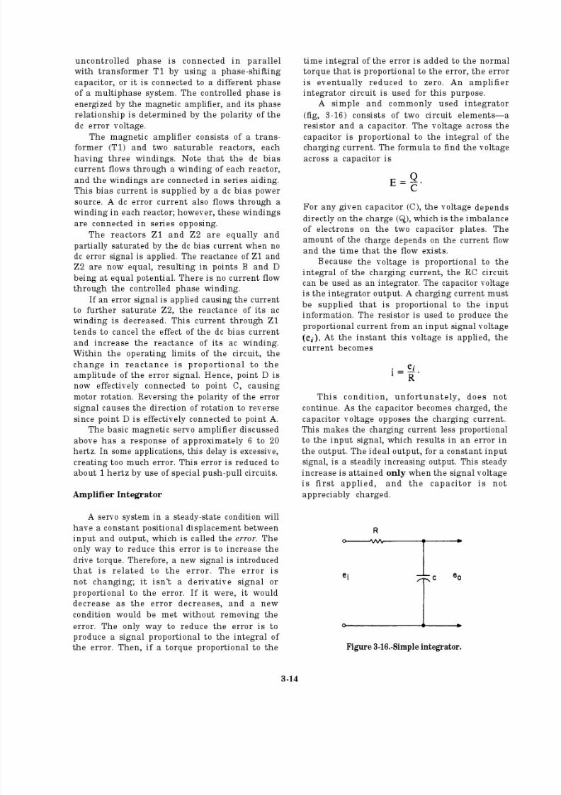
8/14/2019 US Navy Course NAVEDTRA 14028 - Aviation Electronics Technician-Basic
http://slidepdf.com/reader/full/us-navy-course-navedtra-14028-aviation-electronics-technician-basic 125/415
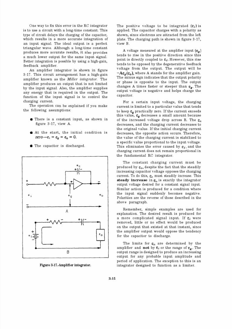
8/14/2019 US Navy Course NAVEDTRA 14028 - Aviation Electronics Technician-Basic
http://slidepdf.com/reader/full/us-navy-course-navedtra-14028-aviation-electronics-technician-basic 126/415
8/14/2019 US Navy Course NAVEDTRA 14028 - Aviation Electronics Technician-Basic
http://slidepdf.com/reader/full/us-navy-course-navedtra-14028-aviation-electronics-technician-basic 127/415
8/14/2019 US Navy Course NAVEDTRA 14028 - Aviation Electronics Technician-Basic
http://slidepdf.com/reader/full/us-navy-course-navedtra-14028-aviation-electronics-technician-basic 128/415
8/14/2019 US Navy Course NAVEDTRA 14028 - Aviation Electronics Technician-Basic
http://slidepdf.com/reader/full/us-navy-course-navedtra-14028-aviation-electronics-technician-basic 129/415

8/14/2019 US Navy Course NAVEDTRA 14028 - Aviation Electronics Technician-Basic
http://slidepdf.com/reader/full/us-navy-course-navedtra-14028-aviation-electronics-technician-basic 130/415
the oscillations in the system, reducing its transittime.
The eddy current damper uses the interaction
of induced eddy currents and a permanent magnetfield to couple the output shaft to a weighted
flywheel. Look at figure 3-18. The solid line shows
the action of the load without damping. Note thetime required to reach a steady-state conditionwithout damping. With damping, this time is
reduced, although the initial overshoot is
increased. You can also see that a viscous
damper effectively reduces transient oscillations,
but it produces an undesired steady-state
error.
How well the load is controlled is a measureof the steady-state performance of a servo system.If the load is moved to an exact given position,then the servo system has a perfect steady-state
performance. If the load is not moved to the exactposition, then the system is not perfect, and thedifference in error is known as the steady-state
error. Steady-state error is either one or both of
the following—a velocity lag or a position error. Velocity error is the steady-state error due to
viscous drag during velocity operation. Position
error is the difference in position between the loadand the position order gi ven to the servo system.
Since the friction damper absorbs power from the
system, its use is normally limited to small
servomechanisms.
Error-rate damping overcomes the disad- vantages of viscous dampers. Error-rate dampingworks by introducing a voltage that is propor-tional to the rate of change of the error signal.The voltage is fed to the servo control amplifier
and combined with the error signal.
Look at figure 3-19. You can see the
effect of error-rate damping on the torque
output of the servomotor. Curve A shows thetorque that results from the error voltage; curveB shows the torque that results from the
error-rate damper; and curve C shows the
resultant of curves A and B.
You should note that the torque that results
from the damper increases the total torque as long
as the error component is increasing. Once the
error component starts to decrease, the error-ratedamper produces a torque in an oppositedirection. This reduces the transit time of thesystem.
Figure 3-18.-Effect of friction damper.
Figure 3-19.-Torque variations using error-rate damping.
3-19
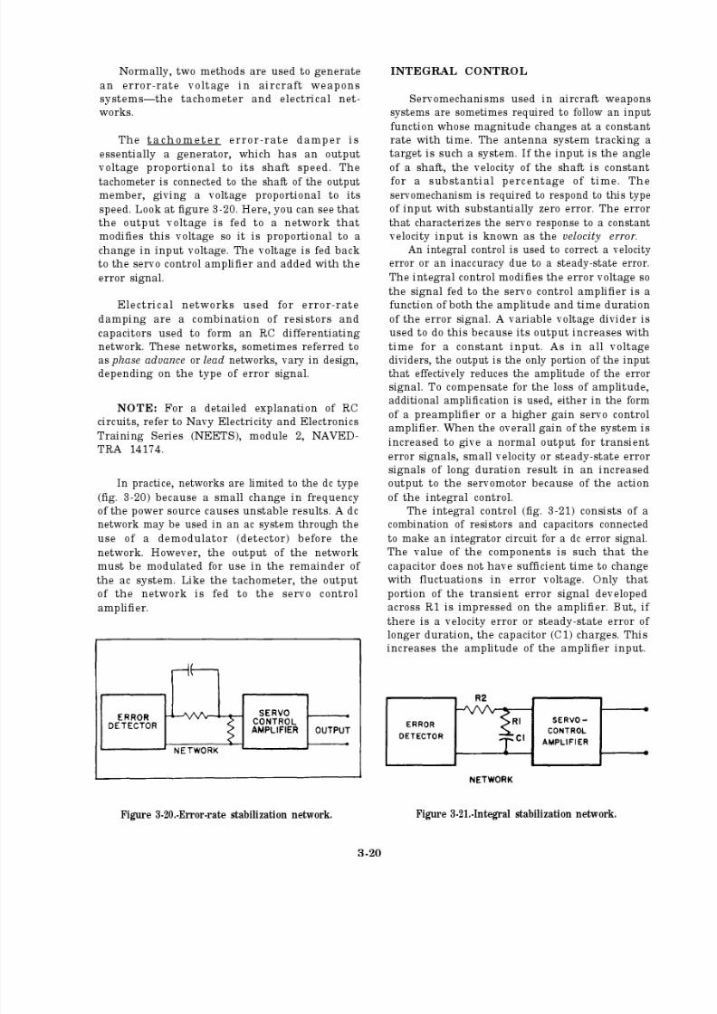
8/14/2019 US Navy Course NAVEDTRA 14028 - Aviation Electronics Technician-Basic
http://slidepdf.com/reader/full/us-navy-course-navedtra-14028-aviation-electronics-technician-basic 131/415
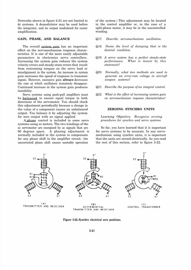
8/14/2019 US Navy Course NAVEDTRA 14028 - Aviation Electronics Technician-Basic
http://slidepdf.com/reader/full/us-navy-course-navedtra-14028-aviation-electronics-technician-basic 132/415
Networks shown in figure 2-21 are not limited to
dc systems. A demodulator may be used before
the integrator, and its output modulated for easieramplification.
GAIN, PHASE, AND BALANCE
The overall system gain has an importanteffect on the servomechanism response charac-teristics. It is one of the more easily adjustable
parameters in electronics servo controllers.Increasing the system gain reduces the system
velocity errors and steady-state errors that result
from restraining torques on the servo load or
misalignment in the system. An increase in system
gain increases the speed of response to transient
inputs. However, excessive gain always decreasesthe rate at which oscillatory transients disappear.
Continued increase in the system gain producesinstability.
Servo systems using push-pull amplifiers mustbe balanced to ensure equal torque in both
directions of the servomotor. You should checkthis adjustment periodically because a change in
the value of a component causes an unbalanced
output. You balance it by adjusting the systemfor zero output with no signal applied.
A phase control is included in some servosystems using ac motors. The two windings of the
ac servomotor are energized by ac signals that are
90 degrees apart. A phasing adjustment isnormally included in the system to compensate
for any phase shift in the amplifier circuit. (An
uncorrected phase shift causes unstable operation
of the system.) This adjustment may be locatedin the control amplifier or, in the case of asplit-phase motor, it may be in the uncontrolledwinding.
Q17.
Q18.
Q19.
Q20.
Q21.
Q22.
Describe servomechanism oscillation.
Name the level of damping that is thedesired condition.
A servo system has a perfect steady-state performance. What is meant by this
statement?
Normally, what two methods are used to
generate an error-rate voltage in aircraftweapon systems?
Describe the purpose of an integral control.
What is the effect of increasing system gainon servomechanism response characteristics?
ZEROING SYNCHRO UNITS
Learning Objective: Recognize zeroing procedures for synchro and servo systems.
So far, you have learned that it is important
for servo systems to be accurate. In any servo-mechanism using synchro units, it is important
that the units are zeroed electrically. As you read
the rest of this section, refer to figure 3-22.
I
Figure 3-22.-Synchro electrical zero positions.
3-21
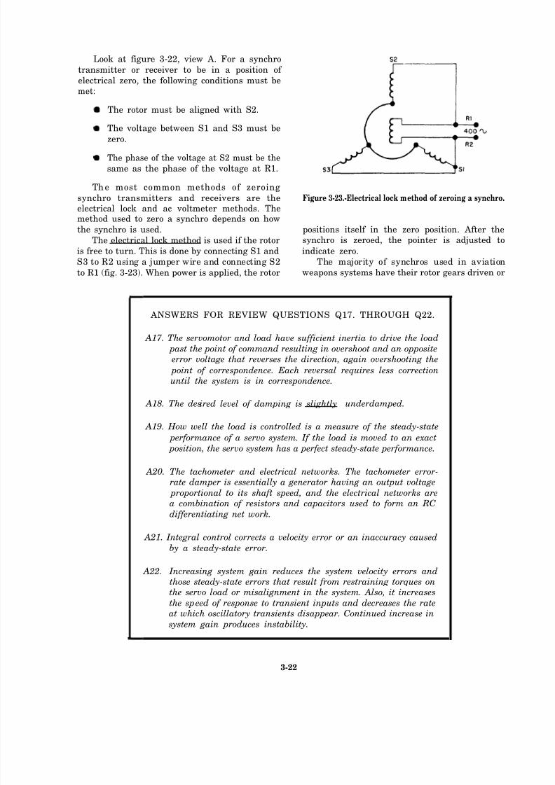
8/14/2019 US Navy Course NAVEDTRA 14028 - Aviation Electronics Technician-Basic
http://slidepdf.com/reader/full/us-navy-course-navedtra-14028-aviation-electronics-technician-basic 133/415
Look at figure 3-22, view A. For a synchro
transmitter or receiver to be in a position of
electrical zero, the following conditions must bemet:
The rotor must be aligned with S2.
The voltage between S1 and S3 must be
zero.
The phase of the voltage at S2 must be the
same as the phase of the voltage at R1.
The most common methods of zeroing
synchro transmitters and receivers are the Figure 3-23.-Electrical lock method of zeroing a synchro.electrical lock and ac voltmeter methods. Themethod used to zero a synchro depends on how
the synchro is used. positions itself in the zero position. After the
The electrical lock method is used if the rotor synchro is zeroed, the pointer is adjusted to
is free to turn. This is done by connecting S1 and indicate zero.
S3 to R2 using a jumper wire and connecting S2 The majority of synchros used in aviation
to R1 (fig. 3-23). When power is applied, the rotor weapons systems have their rotor gears driven or
ANSWERS FOR REVIEW QUESTIONS Q17. THROUGH Q22.
A17. The servomotor and load have sufficient inertia to drive the load
past the point of command resulting in overshoot and an opposite error voltage that reverses the direction, again overshooting the
point of correspondence. Each reversal requires less correctionuntil the system is in correspondence.
A18. The desired level of damping is slightly underdamped.
A19. How well the load is controlled is a measure of the steady-state
performance of a servo system. If the load is moved to an exact
position, the servo system has a perfect steady-state performance.
A20. The tachometer and electrical networks. The tachometer error-rate damper is essentially a generator having an output voltage
proportional to its shaft speed, and the electrical networks area combination of resistors and capacitors used to form an RC
differentiating net work.
A21. Integral control corrects a velocity error or an inaccuracy caused
by a steady-state error.
A22. Increasing system gain reduces the system velocity errors andthose steady-state errors that result from restraining torques onthe servo load or misalignment in the system. Also, it increases
the sp eed of response to transient inputs and decreases the rateat which oscillatory transients disappear. Continued increase in
system gain produces instability.
3-22

8/14/2019 US Navy Course NAVEDTRA 14028 - Aviation Electronics Technician-Basic
http://slidepdf.com/reader/full/us-navy-course-navedtra-14028-aviation-electronics-technician-basic 134/415
mechanically coupled to a driving member. In
these cases, the ac voltmeter method is used tozero the synchro. The synchro is zeroed byrotating the stator or housing until its electricalzero is reached. Before zeroing the synchro, you
must set the mechanical unit that positions the
synchro to its indexing or zeroing position. To dothis, align the unit to this index, and install its
indexing pins in the holes that are provided. The
points hold the unit to its index and keep it frommoving.
The ac voltmeter method is used to zero the
synchro by connecting the meter and jumper wires(fig. 3-24, view A). Rotate the energized synchro
until a zero reading is obtained on the voltmeter.
Since rotor positions of 0 and 180 degrees producethe zero reading, you must determine if the phase
of S2 is the same as R1. Make the connections
shown in figure 3-24, view B. If the proper
polarity relationship exists, the voltmeter indicatesless than the excitation voltage being applied to
Figure 3-24.-Ac voltmeter method of electrically zeroingsynchro receiver or transmitter.
the rotor. If the indication is greater than the rotorexcitation voltage, the rotor or stator must berotated 180 degrees and the previous stepperformed again.
DIFFERENTIAL TRANSMITTER
When the three windings of the rotor are in
correspondence with their respective statorwindings and their respective voltages are in
phase, the synchro differential transmitter or
receiver is in the electrical zero position (fig. 3-22, view B). The differential transmitter synchro isnormally used to insert a correction into a synchro
system; therefore, it is usually driven either
directly or through a gear train. Before you zero
the differential transmitter synchro, zero the unitwhose position the differential synchro transmits
first. After doing this, connect the differential
synchro, as shown in figure 3-25, view A. Turnthe synchro in its mounting until the voltmetershows a minimum indication. Then, make the
connections shown in figure 3-25, view B. Again, turn the synchro slightly in its mounting
until a minimum voltage is indicated by the
voltmeter.
DIFFERENTIAL RECEIVER
Look at figure 3-22, view B. It shows the
electrical zero for a differential receiver. To zeroa diff erential receiver synchro, you make the
Figure 3-25.-Electrically zeroing a differential transmitter.
3-23
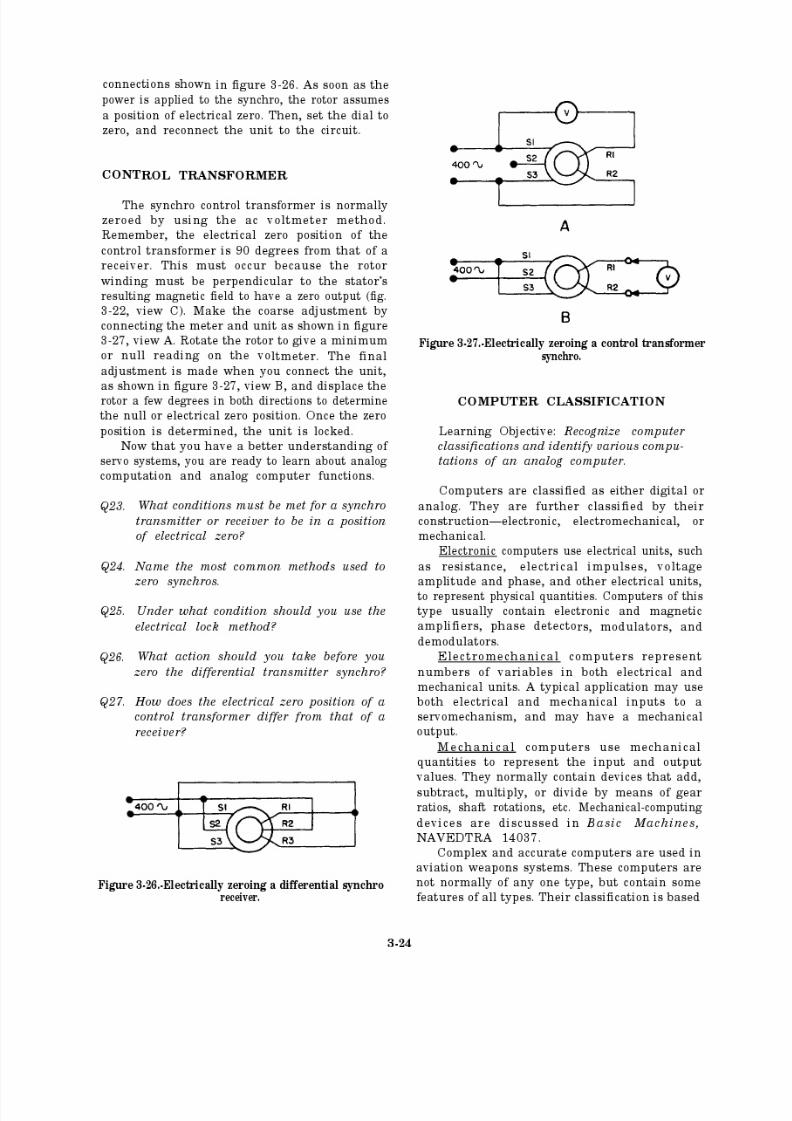
8/14/2019 US Navy Course NAVEDTRA 14028 - Aviation Electronics Technician-Basic
http://slidepdf.com/reader/full/us-navy-course-navedtra-14028-aviation-electronics-technician-basic 135/415
8/14/2019 US Navy Course NAVEDTRA 14028 - Aviation Electronics Technician-Basic
http://slidepdf.com/reader/full/us-navy-course-navedtra-14028-aviation-electronics-technician-basic 136/415
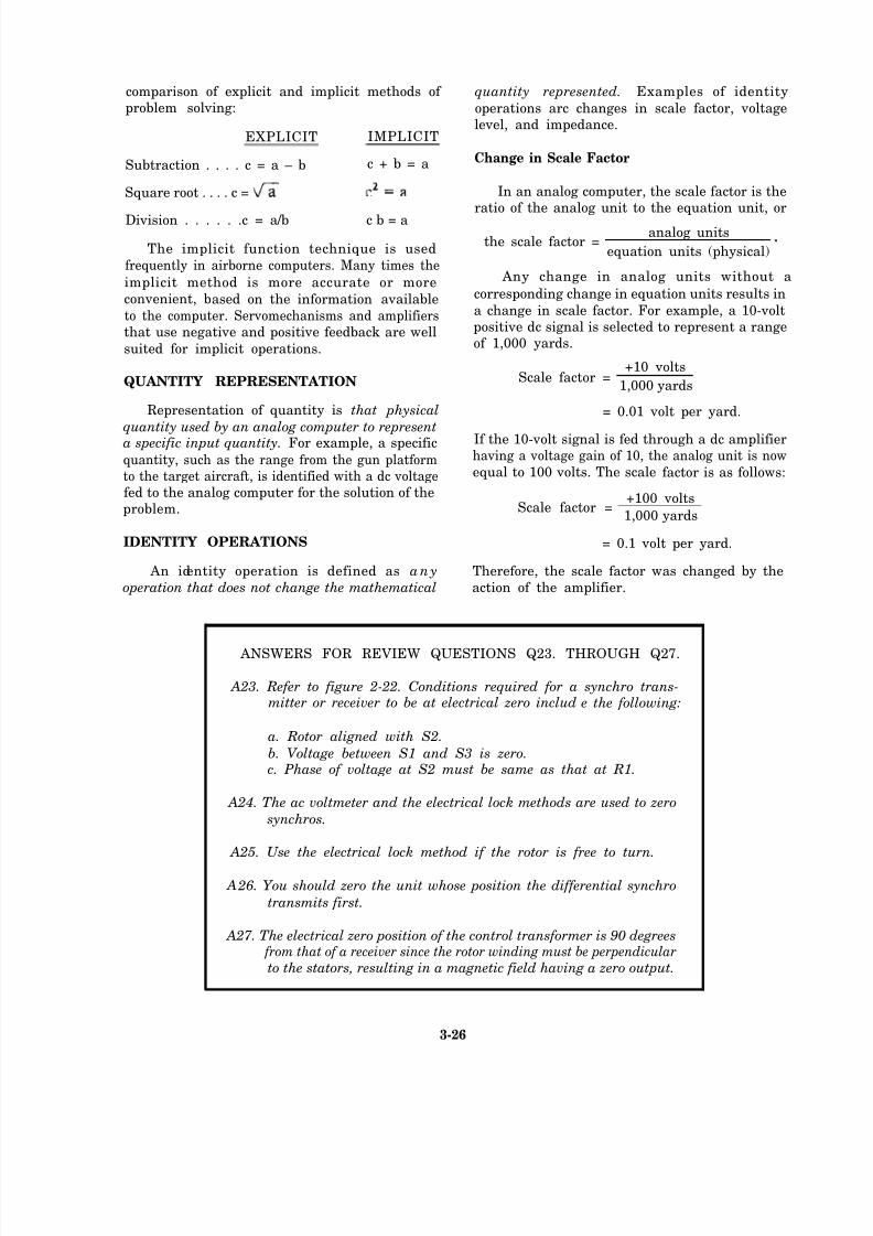
8/14/2019 US Navy Course NAVEDTRA 14028 - Aviation Electronics Technician-Basic
http://slidepdf.com/reader/full/us-navy-course-navedtra-14028-aviation-electronics-technician-basic 137/415
comparison of explicit and implicit methods of
problem solving:
EXPLICIT IMPLICIT
Subtraction . . . . c = a – b c + b = a
Square root . . . . c =
Division . . . . . .c = a/b c b = a
The implicit function technique is used
frequently in airborne computers. Many times the
implicit method is more accurate or more
convenient, based on the information available
to the computer. Servomechanisms and amplifiers
that use negative and positive feedback are well
suited for implicit operations.
QUANTITY REPRESENTATION
Representation of quantity is that physical
quantity used by an analog computer to representa specific input quantity. For example, a specific
quantity, such as the range from the gun platform
to the target aircraft, is identified with a dc voltage
fed to the analog computer for the solution of the
problem.
IDENTITY OPERATIONS
An identity operation is defined as a n y
quantity represented. Examples of identity
operations arc changes in scale factor, voltage
level, and impedance.
Change in Scale Factor
In an analog computer, the scale factor is the
ratio of the analog unit to the equation unit, or
the scale factor =analog units
equation units (physical)
Any change in analog units without a
corresponding change in equation units results in
a change in scale factor. For example, a 10-volt
positive dc signal is selected to represent a range
of 1,000 yards.
Scale factor =+10 volts
1,000 yards
= 0.01 volt per yard.
If the 10-volt signal is fed through a dc amplifier
having a voltage gain of 10, the analog unit is now
equal to 100 volts. The scale factor is as follows:
Scale factor =+100 volts
1,000 yards
= 0.1 volt per yard.
Therefore, the scale factor was changed by the
operation that does not change the mathematical action of the amplifier.
ANSWERS FOR REVIEW QUESTIONS Q23. THROUGH Q27.
A23. Refer to figure 2-22. Conditions required for a synchro trans-mitter or receiver to be at electrical zero includ e the following:
a. Rotor aligned with S2.
b. Voltage between S1 and S3 is zero.c. Phase of voltage at S2 must be same as that at R1.
A24. The ac voltmeter and the electrical lock methods are used to zero
synchros.
A25. Use the electrical lock method if the rotor is free to turn.
A 26. You should zero the unit whose position the differential synchro
transmits first.
A27. The electrical zero position of the control transformer is 90 degrees from that of a receiver since the rotor winding must be perpendicular
to the stators, resulting in a magnetic field having a zero output.
3-26
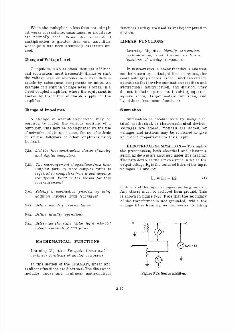
8/14/2019 US Navy Course NAVEDTRA 14028 - Aviation Electronics Technician-Basic
http://slidepdf.com/reader/full/us-navy-course-navedtra-14028-aviation-electronics-technician-basic 138/415
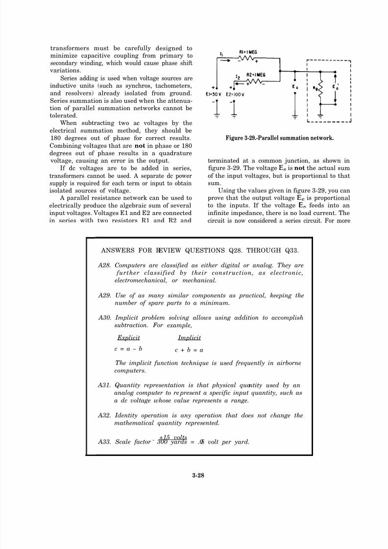
8/14/2019 US Navy Course NAVEDTRA 14028 - Aviation Electronics Technician-Basic
http://slidepdf.com/reader/full/us-navy-course-navedtra-14028-aviation-electronics-technician-basic 139/415
transformers must be carefully designed tominimize capacitive coupling from primary tosecondary winding, which would cause phase shift
variations.
Series adding is used when voltage sources areinductive units (such as synchros, tachometers,
and resolvers) already isolated from ground.Series summation is also used when the attenua-tion of parallel summation networks cannot betolerated.
When subtracting two ac voltages by the
electrical summation method, they should be
180 degrees out of phase for correct results.
Combining voltages that are not in phase or 180degrees out of phase results in a quadrature voltage, causing an error in the output.
If dc voltages are to be added in series,
transformers cannot be used. A separate dc powersupply is required for each term or input to obtain
isolated sources of voltage. A parallel resistance network can be used to
electrically produce the algebraic sum of several
input voltages. Voltages E1 and E2 are connected
in series with two resistors R1 and R2 and
Figure 3-29.-Parallel summation network.
terminated at a common junction, as shown infigure 3-29. The voltage is not the actual sum
of the input voltages, but is proportional to thatsum.
Using the values given in figure 3-29, you canprove that the output voltage is proportionalto the inputs. If the voltage feeds into an
infinite impedance, there is no load current. The
circuit is now considered a series circuit. For more
ANSWERS FOR REVIEW QUESTIONS Q28. THROUGH Q33.
A28. Computers are classified as either digital or analog. They are
further classified by their construction, as electronic,
electromechanical, or mechanical.
A29. Use of as many similar components as practical, keeping the
number of spare parts to a minimum.
A30. Implicit problem solving allows using addition to accomplish
subtraction. For example,
Explicit Implicit
c = a – b c + b = a
The implicit function technique is used frequently in airborne
computers.
A31. Quantity representation is that physical quantity used by ananalog computer to re present a specific input quantity, such as
a dc voltage whose value represents a range.
A32. Identity operation is any operation that does not change the
mathematical quantity represented.
+15 volts A33. Scale factor
= 300 yards = .05 volt per yard.
3-28

8/14/2019 US Navy Course NAVEDTRA 14028 - Aviation Electronics Technician-Basic
http://slidepdf.com/reader/full/us-navy-course-navedtra-14028-aviation-electronics-technician-basic 140/415
information about electrical summation, you
should refer to Naval Electricity and Electronics
Training Series (NEETS), module 15, Principles
of Synchros, Servos, and Gyros, NAVEDTRA14187. Therefore,
I1 = 12. (2)
Then, since all branches are parallel,
E1 + I1R1 = E2 – I2R2 = (3)
Solving for the currents in each part of equation
(3) and substituting the results into equation (2),
Solving equation (4) for
or, by further simplication,
(4)
(5)
(6)
Therefore, an expression for voltage was
obtained in terms of the sum of the two input voltages and their respective series resistors.
The voltage was obtained by assuming a
very high-impedance load. If a grid resistor
is included, the voltage is determined by
As you know, the voltage output is not
the actual sum of the input voltages, but isproportional to that sum. The following exampleillustrates this proportionality:
E1 = 50 volts E2 = 100 volts
R1 = 1 megohm R2 = 1 megohm
Then, using equation (5),
If were the actual sum of the input voltages,
the voltage output would be 150 volts. However,
this difference in actual sum and proportional voltage is compensated for by a change in scale
factor. When a difference between two terms isrequired (subtracted), a negative voltage is used
to represent the quantity being subtracted. Boththe negative and positive voltages are fed to theparallel resistance network.
Scale Factor.— Although addition is a sum-mation of voltages, the computer’s real job is to
add physical units, such as feet per second ordegrees per minute. The proper application of scale factors makes the addition of the physical
units of an equation possible. The following
transformation formula is used for this purpose:
Equation units x scale factor = analog units.
When the physical inputs to the analog
computer are represented by voltages, the finalsolution in the proper units is found by dividingthe summed voltages by the output scale factor.If the voltages E1 and E2 in figure 3-30 were
chosen to represent 1,000 feet each, the scalefactor for the input voltages would be 1 volt per10 feet, and should be written as 1 volt/10 feet.
Figure 3-30.-Scale factors assigned tosummation networks.
parallel resistor
3-29
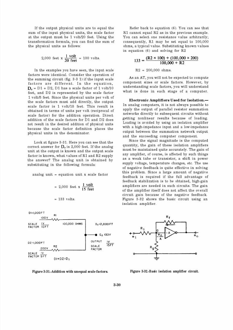
8/14/2019 US Navy Course NAVEDTRA 14028 - Aviation Electronics Technician-Basic
http://slidepdf.com/reader/full/us-navy-course-navedtra-14028-aviation-electronics-technician-basic 141/415

8/14/2019 US Navy Course NAVEDTRA 14028 - Aviation Electronics Technician-Basic
http://slidepdf.com/reader/full/us-navy-course-navedtra-14028-aviation-electronics-technician-basic 142/415
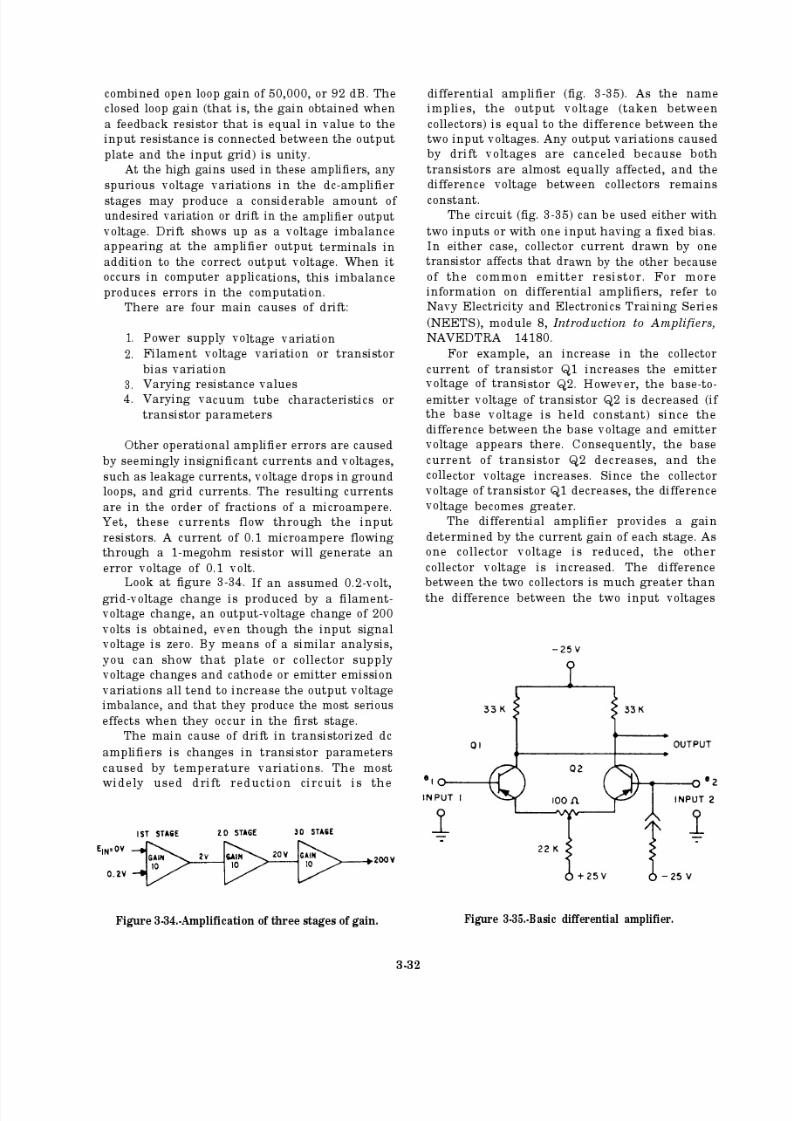
8/14/2019 US Navy Course NAVEDTRA 14028 - Aviation Electronics Technician-Basic
http://slidepdf.com/reader/full/us-navy-course-navedtra-14028-aviation-electronics-technician-basic 143/415
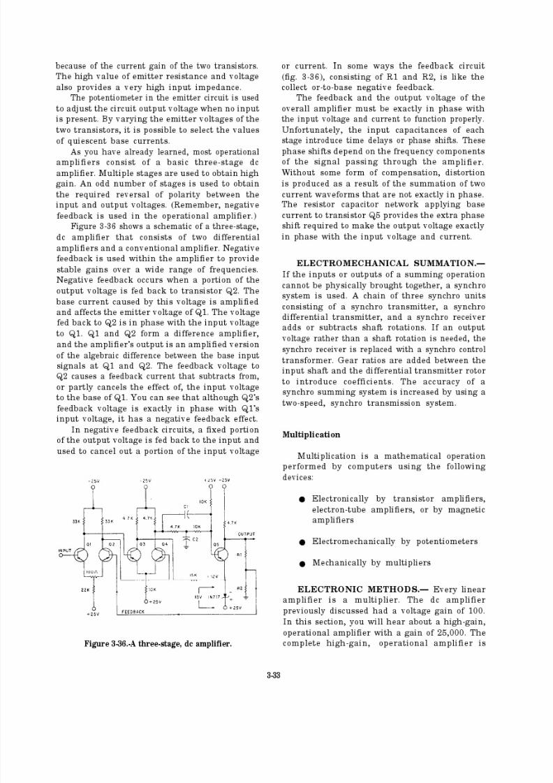
8/14/2019 US Navy Course NAVEDTRA 14028 - Aviation Electronics Technician-Basic
http://slidepdf.com/reader/full/us-navy-course-navedtra-14028-aviation-electronics-technician-basic 144/415
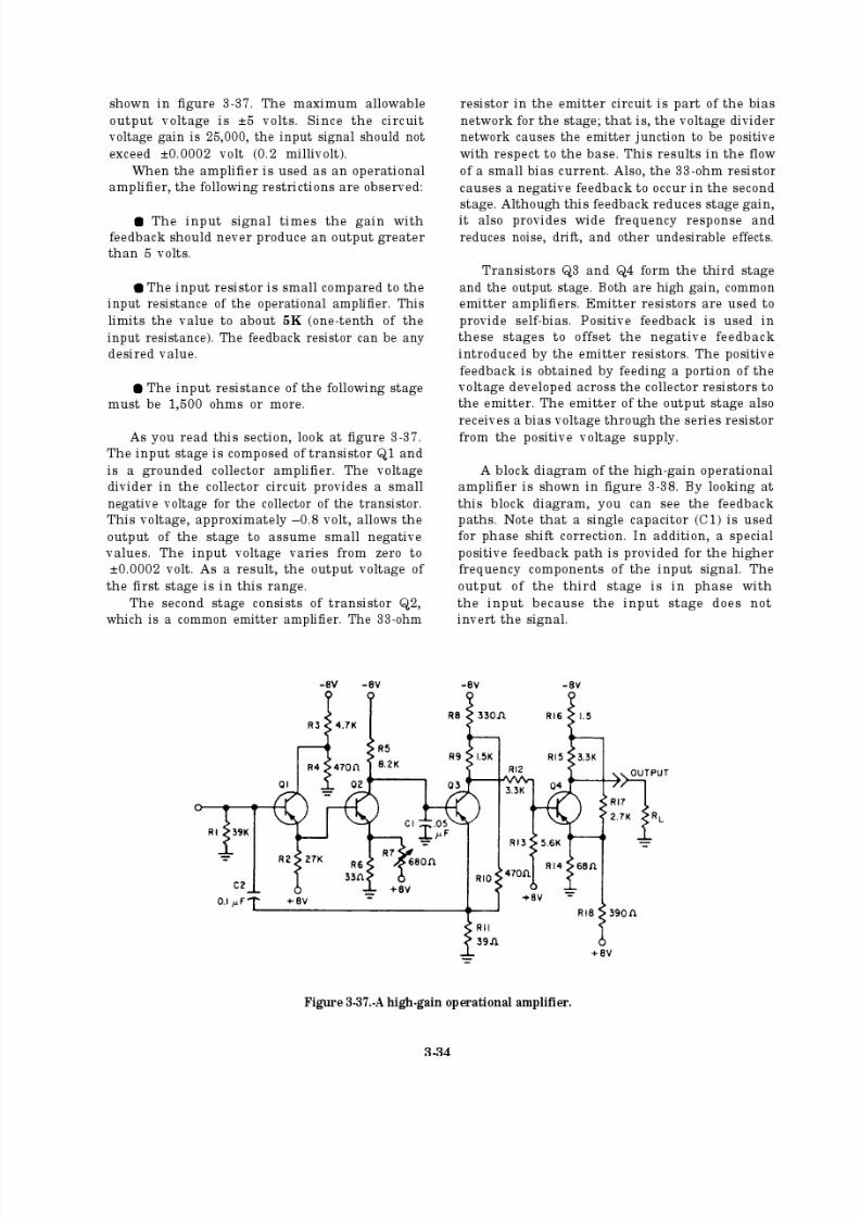
8/14/2019 US Navy Course NAVEDTRA 14028 - Aviation Electronics Technician-Basic
http://slidepdf.com/reader/full/us-navy-course-navedtra-14028-aviation-electronics-technician-basic 145/415

8/14/2019 US Navy Course NAVEDTRA 14028 - Aviation Electronics Technician-Basic
http://slidepdf.com/reader/full/us-navy-course-navedtra-14028-aviation-electronics-technician-basic 146/415
Figure 3-38.-Block diagram of a high-gain operationalamplifier.
External feedback resistors are also shown in
the block diagram. The gain, with feedback, can
be varied from 1 (input resistor of 4.7K and
feedback resistance of 4.7K) to 10 (input resistor
of 4.7K and feedback resistance of 47K). Higher
gains are obtained by using higher values of feedback resistance. In most analog computer
applications, a gain of 10 is sufficient. Feedback
in amplifiers is discussed in detail in Navy
Electricity and Electronics Training Series
(NEETS), module 8, Introduction to Ampli fiers,
NAVEDTRA 14180.
Electron tube amplifiers are also capable of
solving multiplication problems involving two variables as represented by the equation
= kxy.
Figure 3-39 shows a typical triode multiplicationcircuit. One variable input is applied as grid bias
(preferably a dc voltage), which establishes the
gain of the stage. The other variable input is
applied to the grid of the tube.The output is a proportional quantity equal
to the grid signal modified by the gain, which is
Figure 3-39.-Variable-gains tube as a multiplier circuit.
proportional to the variable bias voltage. This
circuit is limited in scope and accuracy due to
variations in tube characteristics, contact
potential, plate and filament supply changes, etc.
An improved multiplying circuit is shown in
figure 3-40, view A. Its operation is like the circuit
shown in figure 3-39 except that it uses two
separate grids. The voltage gain of the stage iscontrolled by the voltage on grid 3 (shown by the
curve in figure 3-40, view B).
The gain of the amplifier is proportional to
the voltage and may be expressed as follows:
A =
If the output voltage is directly proportional
to the input signal is
=
Substituting for A, the equation reads
=
The output is a proportional quantity as indicated
by the constant k.
Figure 3-40 .-A multielectrode tube used as a multiplier.
3-35
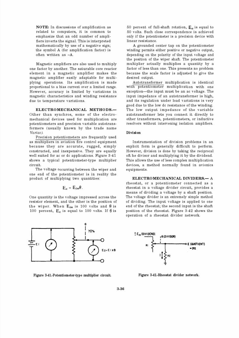
8/14/2019 US Navy Course NAVEDTRA 14028 - Aviation Electronics Technician-Basic
http://slidepdf.com/reader/full/us-navy-course-navedtra-14028-aviation-electronics-technician-basic 147/415
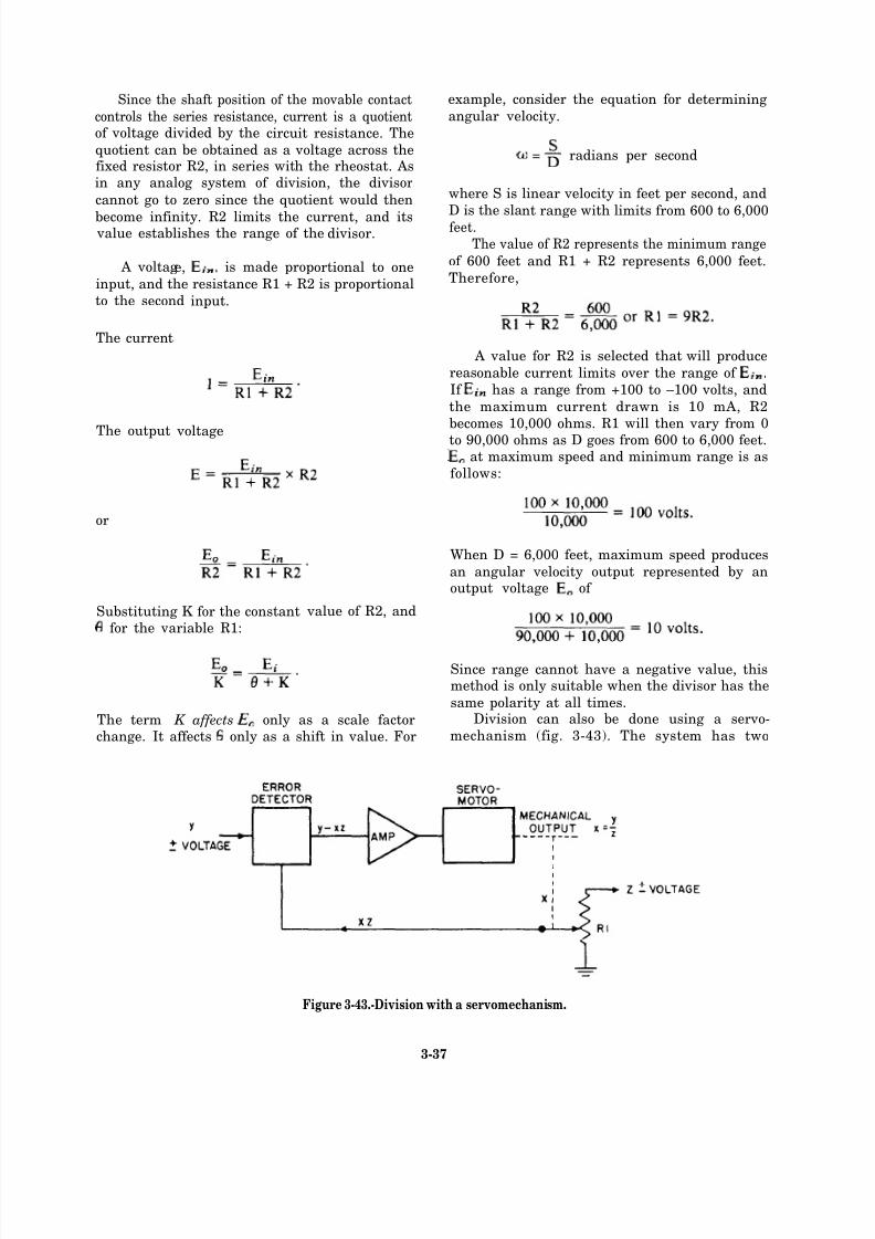
8/14/2019 US Navy Course NAVEDTRA 14028 - Aviation Electronics Technician-Basic
http://slidepdf.com/reader/full/us-navy-course-navedtra-14028-aviation-electronics-technician-basic 148/415
Since the shaft position of the movable contact
controls the series resistance, current is a quotientof voltage divided by the circuit resistance. The
quotient can be obtained as a voltage across thefixed resistor R2, in series with the rheostat. Asin any analog system of division, the divisor
cannot go to zero since the quotient would then
become infinity. R2 limits the current, and its value establishes the range of the divisor.
A voltage, is made proportional to one
input, and the resistance R1 + R2 is proportional
to the second input.
The current
The output voltage
example, consider the equation for determining
angular velocity.
= radians per second
where S is linear velocity in feet per second, and
D is the slant range with limits from 600 to 6,000feet.The value of R2 represents the minimum range
of 600 feet and R1 + R2 represents 6,000 feet.
Therefore,
A value for R2 is selected that will produce
reasonable current limits over the range of
If has a range from +100 to –100 volts, and
the maximum current drawn is 10 mA, R2
becomes 10,000 ohms. R1 will then vary from 0to 90,000 ohms as D goes from 600 to 6,000 feet.
at maximum speed and minimum range is as
or
Substituting K for the constantfor the variable R1:
value of R2, and
The term K affects only as a scale factorchange. It affects only as a shift in value. For
follows:
When D = 6,000 feet, maximum speed produces
an angular velocity output represented by anoutput voltage of
Since range cannot have a negative value, thismethod is only suitable when the divisor has the
same polarity at all times.Division can also be done using a servo-
mechanism (fig. 3-43). The system has two
Figure 3-43.-Division with a servomechanism.
3-37
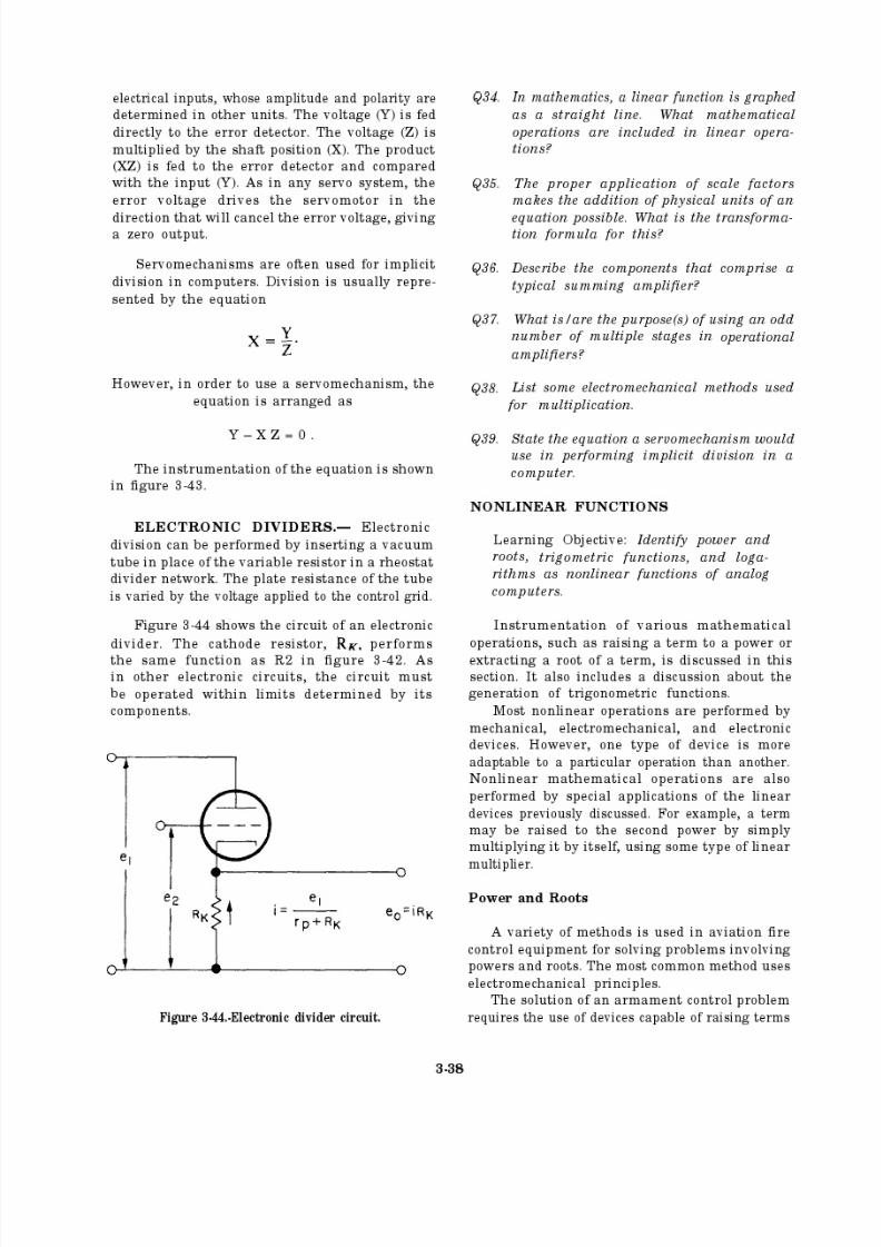
8/14/2019 US Navy Course NAVEDTRA 14028 - Aviation Electronics Technician-Basic
http://slidepdf.com/reader/full/us-navy-course-navedtra-14028-aviation-electronics-technician-basic 149/415
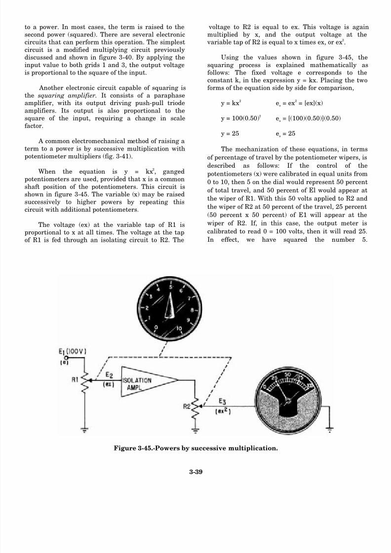
8/14/2019 US Navy Course NAVEDTRA 14028 - Aviation Electronics Technician-Basic
http://slidepdf.com/reader/full/us-navy-course-navedtra-14028-aviation-electronics-technician-basic 150/415
to a power. In most cases, the term is raised to thesecond power (squared). There are several electroniccircuits that can perform this operation. The simplest
circuit is a modified multiplying circuit previouslydiscussed and shown in figure 3-40. By applying theinput value to both grids 1 and 3, the output voltageis proportional to the square of the input.
Another electronic circuit capable of squaring is
the squaring amplifier. It consists of a paraphaseamplifier, with its output driving push-pull triode
amplifiers. Its output is also proportional to thesquare of the input, requiring a change in scalefactor.
A common electromechanical method of raising aterm to a power is by successive multiplication withpotentiometer multipliers (fig. 3-41).
When the equation is y = kx2
, gangedpotentiometers are used, provided that x is a commonshaft position of the potentiometers. This circuit is
shown in figure 3-45. The variable (x) may be raisedsuccessively to higher powers by repeating thiscircuit with additional potentiometers.
The voltage (ex) at the variable tap of R1 isproportional to x at all times. The voltage at the tapof R1 is fed through an isolating circuit to R2. The
voltage to R2 is equal to ex. This voltage is againmultiplied by x, and the output voltage at the
variable tap of R2 is equal to x times ex, or ex2
.
Using the values shown in figure 3-45, the
squaring process is explained mathematically asfollows: The fixed voltage e corresponds to theconstant k, in the expression y = kx. Placing the twoforms of the equation side by side for comparison,
y = kx2
eo= ex
2
= [ex](x)
y = 100(0.50)2
eo= [(100)(0.50)](0.50)
y = 25 eo= 25
The mechanization of these equations, in terms
of percentage of travel by the potentiometer wipers, is
described as follows: If the control of the
potentiometers (x) were calibrated in equal units from
0 to 10, then 5 on the dial would represent 50 percent
of total travel, and 50 percent of El would appear at
the wiper of R1. With this 50 volts applied to R2 and
the wiper of R2 at 50 percent of the travel, 25 percent
(50 percent x 50 percent) of E1 will appear at the
wiper of R2. If, in this case, the output meter is
calibrated to read 0 = 100 volts, then it will read 25
In effect, we have squared the number 5
Figure 3-45.-Powers by successive multiplication.
3-39
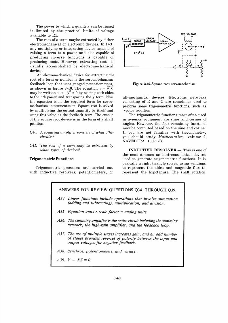
8/14/2019 US Navy Course NAVEDTRA 14028 - Aviation Electronics Technician-Basic
http://slidepdf.com/reader/full/us-navy-course-navedtra-14028-aviation-electronics-technician-basic 151/415
The power to which a quantity can be raised
is limited by the practical limits of voltage
available to R1.The root of a term maybe extracted by either
electromechanical or electronic devices. In fact,any multiplying or integrating device capable of raising a term to a power and also capable of
producing inverse functions is capable of producing roots. However, extracting roots is
usually accomplished by electromechanical
devices.
An electromechanical device for extracting theroot of a term or number is the servomechanism
feedback loop that uses ganged potentiometers,
as shown in figure 3-46. The equation y =may be written as x – = 0 by raising both sidesto the nth power and transposing the y term. Now
the equation is in the required form for servo-mechanism instrumentation. Square root is solved
by multiplying the output quantity by itself and
using this value as the feedback term. The outputof the square root device is in the form of a shaftposition.
Figure 3-46.-Square root servomechanism.
all-mechanical devices. Electronic networksconsisting of R and C are sometimes used to
perform some trigonometric functions, such as vector addition.
The trigonometric functions most often usedin avionics equipment are sines and cosines of angles. However, the four remaining functions
Q40.
Q41.
may be computed based on the sine and cosine. A squaring amplifier consists of what other If you are not familiar with trigonometry,circuits? you should study Mathematics, volume 2,
NAVEDTRA 10071-B.The root of a term may be extracted by
what types of devices? INDUCTIVE RESOLVER.— This is one of
the most common ac electromechanical devicesTrigonometric Functions used to generate trigonometric functions. It is
basically a right triangle solver, using windingsTrigonometric processes are carried out to represent the sides and magnetic flux to
with inductive resolvers, potentiometers, or represent the hypotenuse. The shaft rotation
3-40
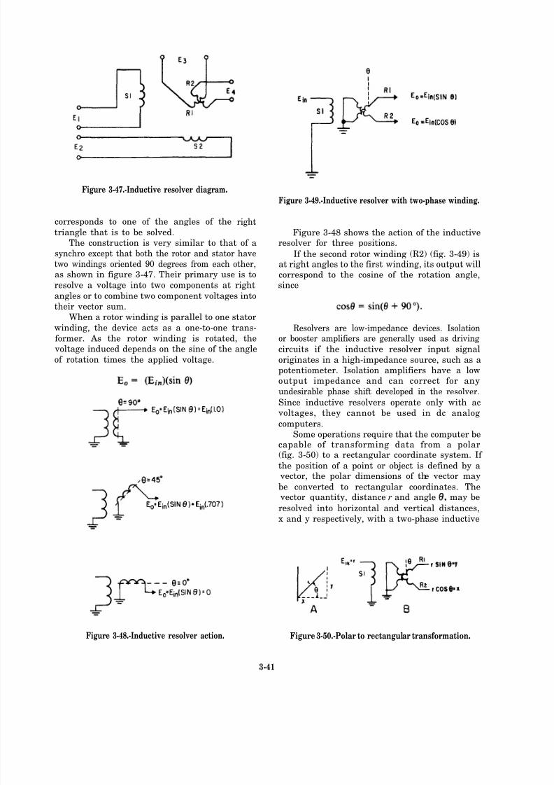
8/14/2019 US Navy Course NAVEDTRA 14028 - Aviation Electronics Technician-Basic
http://slidepdf.com/reader/full/us-navy-course-navedtra-14028-aviation-electronics-technician-basic 152/415
Figure 3-47.-Inductive resolver diagram.
corresponds to one of the angles of the
triangle that is to be solved.The construction is very similar to that of a
synchro except that both the rotor and stator havetwo windings oriented 90 degrees from each other,
as shown in figure 3-47. Their primary use is toresolve a voltage into two components at right
angles or to combine two component voltages into
their vector sum.When a rotor winding is parallel to one stator
winding, the device acts as a one-to-one trans-
former. As the rotor winding is rotated, the voltage induced depends on the sine of the angle
of rotation times the applied voltage.
Figure 3-49.-Inductive resolver with two-phase winding.
right
Figure 3-48.-Inductive resolver action.
Figure 3-48 shows the action of the inductiveresolver for three positions.
If the second rotor winding (R2) (fig. 3-49) isat right angles to the first winding, its output will
correspond to the cosine of the rotation angle,since
Resolvers are low-impedance devices. Isolationor booster amplifiers are generally used as driving
circuits if the inductive resolver input signal
originates in a high-impedance source, such as apotentiometer. Isolation amplifiers have a lowoutput impedance and can correct for any
undesirable phase shift developed in the resolver.
Since inductive resolvers operate only with ac
voltages, they cannot be used in dc analogcomputers.
Some operations require that the computer becapable of transforming data from a polar(fig. 3-50) to a rectangular coordinate system. If
the position of a point or object is defined by a vector, the polar dimensions of the vector may
be converted to rectangular coordinates. The vector quantity, distance r and angle may be
resolved into horizontal and vertical distances,
x and y respectively, with a two-phase inductive
Figure 3-50.-Polar to rectangular transformation.
3-41
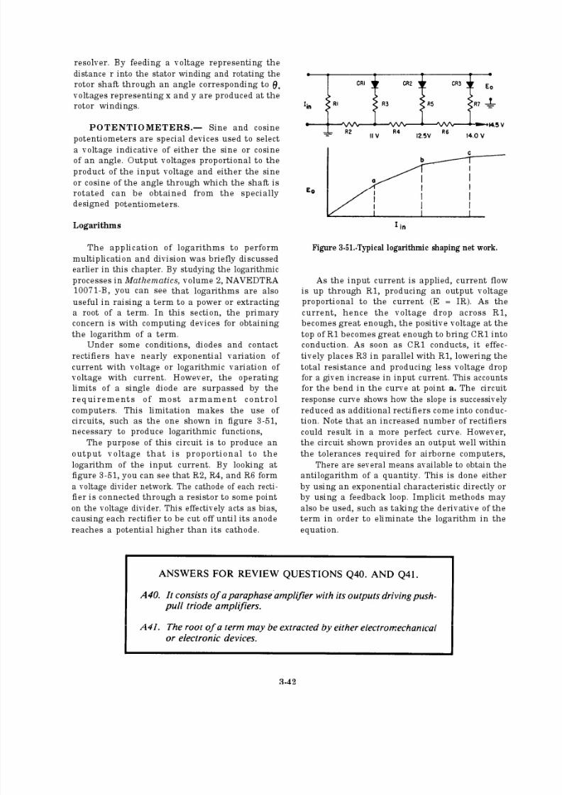
8/14/2019 US Navy Course NAVEDTRA 14028 - Aviation Electronics Technician-Basic
http://slidepdf.com/reader/full/us-navy-course-navedtra-14028-aviation-electronics-technician-basic 153/415
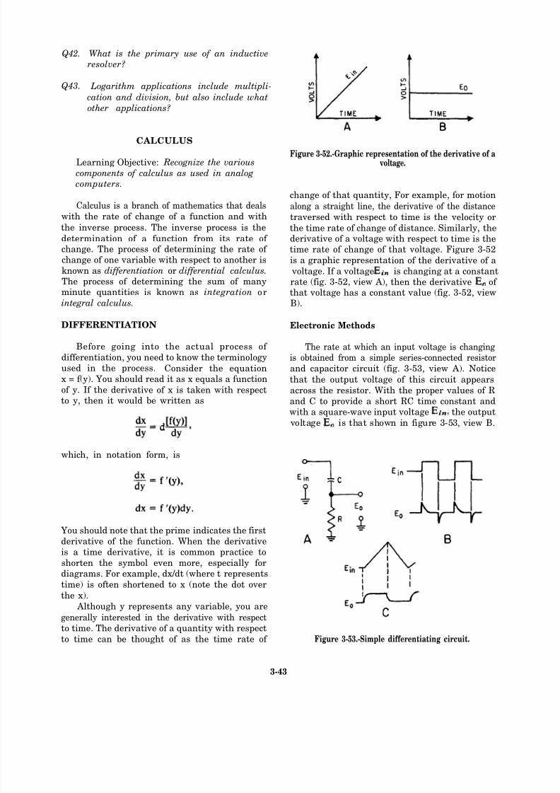
8/14/2019 US Navy Course NAVEDTRA 14028 - Aviation Electronics Technician-Basic
http://slidepdf.com/reader/full/us-navy-course-navedtra-14028-aviation-electronics-technician-basic 154/415
Q42.
Q43.
What is the primary use of an inductive
resolver?
Logarithm applications include multipli-
cation and division, but also include what
other applications?
CALCULUS
Learning Objective: Recognize the various
components of calculus as used in analog
computers.
Calculus is a branch of mathematics that deals
with the rate of change of a function and with
the inverse process. The inverse process is the
determination of a function from its rate of change. The process of determining the rate of change of one variable with respect to another is
known as differentiation or differential calculus.
The process of determining the sum of manyminute quantities is known as inte gration orintegral calculus.
DIFFERENTIATION
Before going into the actual process of
differentiation, you need to know the terminologyused in the process. Consider the equationx = f(y). You should read it as x equals a function
of y. If the derivative of x is taken with respectto y, then it would be written as
which, in notation form, is
You should note that the prime indicates the first
derivative of the function. When the derivative
is a time derivative, it is common practice toshorten the symbol even more, especially fordiagrams. For example, dx/dt (where t represents
time) is often shortened to x (note the dot over
the x).
Although y represents any variable, you are
generally interested in the derivative with respectto time. The derivative of a quantity with respect
to time can be thought of as the time rate of
Figure 3-52.-Graphic representation of the derivative of avoltage.
change of that quantity, For example, for motion
along a straight line, the derivative of the distance
traversed with respect to time is the velocity or
the time rate of change of distance. Similarly, thederivative of a voltage with respect to time is thetime rate of change of that voltage. Figure 3-52
is a graphic representation of the derivative of a
voltage. If a voltage is changing at a constantrate (fig. 3-52, view A), then the derivative of that voltage has a constant value (fig. 3-52, viewB).
Electronic Methods
The rate at which an input voltage is changingis obtained from a simple series-connected resistor
and capacitor circuit (fig. 3-53, view A). Notice
that the output voltage of this circuit appears
across the resistor. With the proper values of R
and C to provide a short RC time constant andwith a square-wave input voltage the output
voltage is that shown in figure 3-53, view B.
Figure 3-53.-Simple differentiating circuit.
3-43
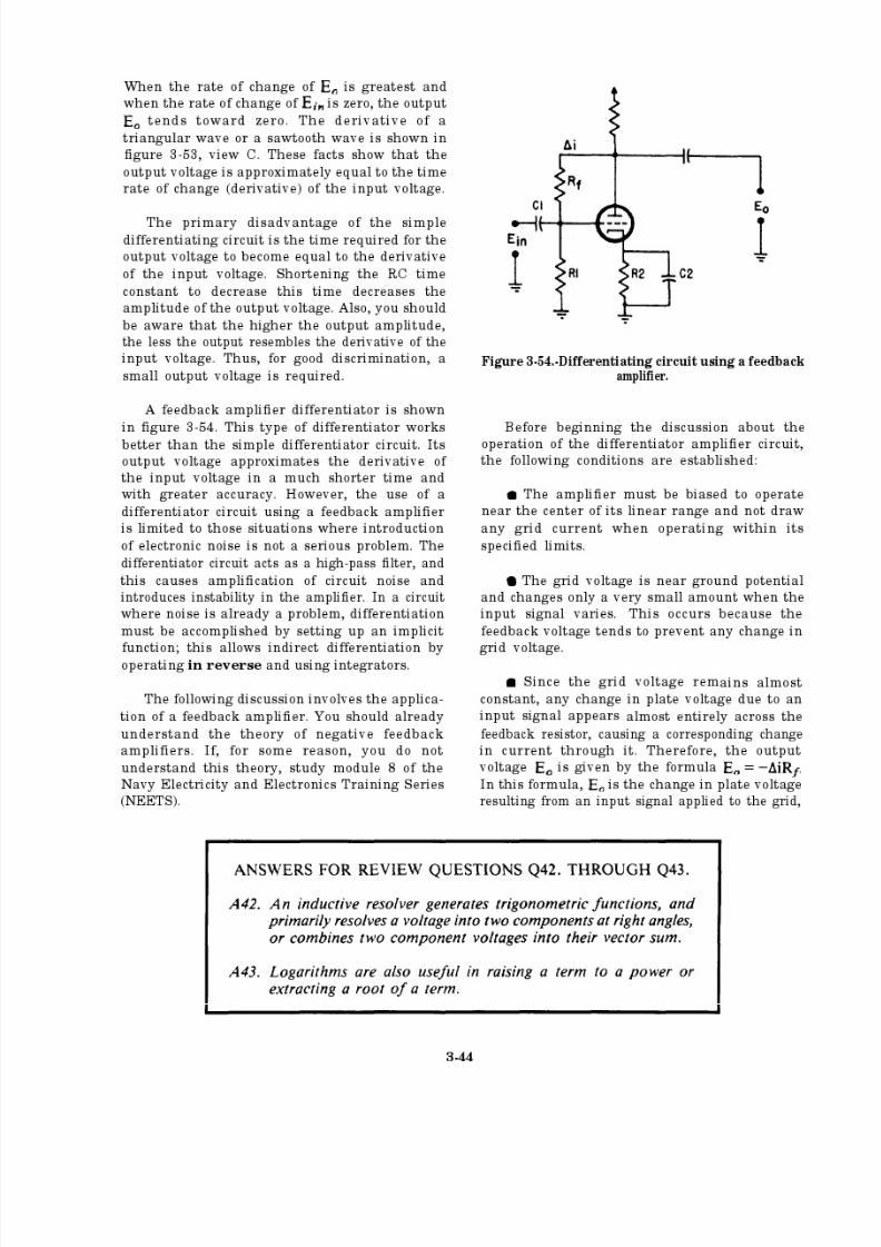
8/14/2019 US Navy Course NAVEDTRA 14028 - Aviation Electronics Technician-Basic
http://slidepdf.com/reader/full/us-navy-course-navedtra-14028-aviation-electronics-technician-basic 155/415
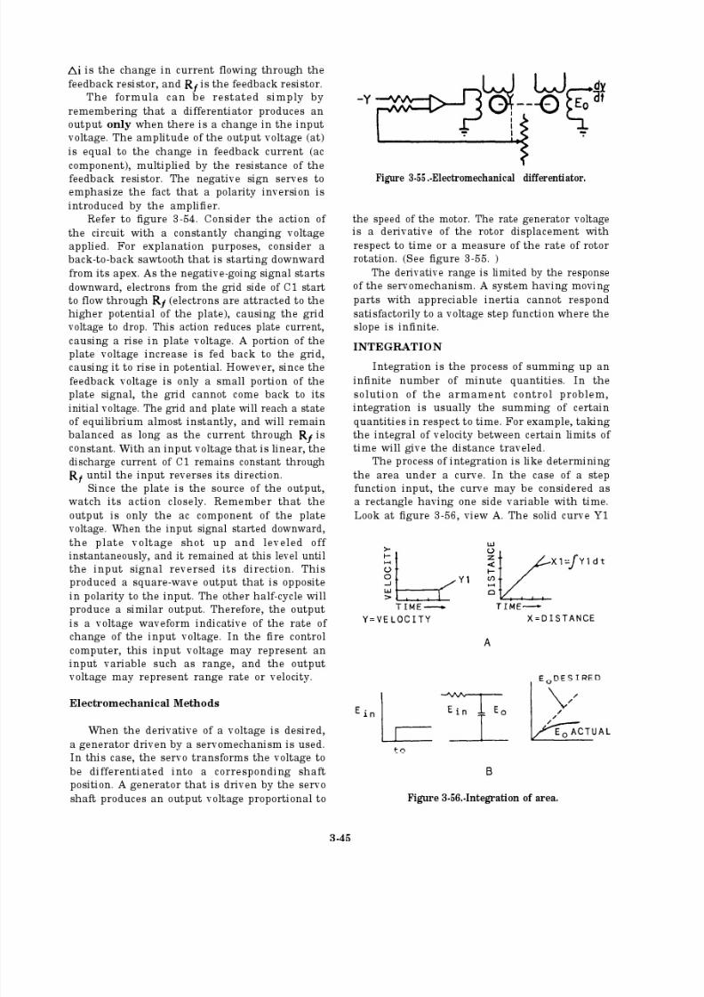
8/14/2019 US Navy Course NAVEDTRA 14028 - Aviation Electronics Technician-Basic
http://slidepdf.com/reader/full/us-navy-course-navedtra-14028-aviation-electronics-technician-basic 156/415
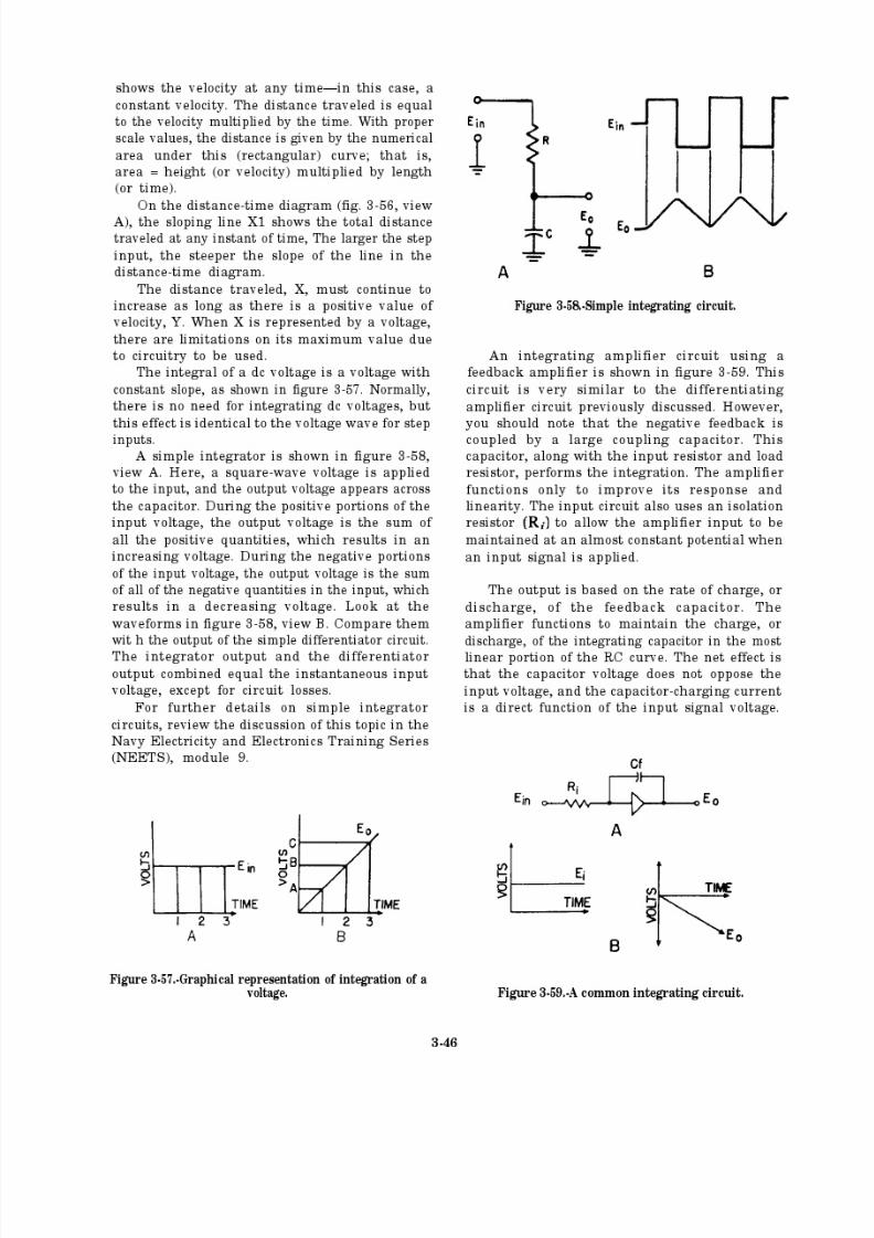
8/14/2019 US Navy Course NAVEDTRA 14028 - Aviation Electronics Technician-Basic
http://slidepdf.com/reader/full/us-navy-course-navedtra-14028-aviation-electronics-technician-basic 157/415
8/14/2019 US Navy Course NAVEDTRA 14028 - Aviation Electronics Technician-Basic
http://slidepdf.com/reader/full/us-navy-course-navedtra-14028-aviation-electronics-technician-basic 158/415

8/14/2019 US Navy Course NAVEDTRA 14028 - Aviation Electronics Technician-Basic
http://slidepdf.com/reader/full/us-navy-course-navedtra-14028-aviation-electronics-technician-basic 159/415
requires a constant solution from the following
equation:
where
r = slant range
H = altitude
R = ground range
A block diagram of a squaring-type triangle
solver is shown in figure 3-60. The quantities Hand R are squared and summed. The summedquantity + is fed to a device that extractsthe square root, giving an output equal to r.
Figure 3-60.-Block diagram of right triangle solver.
A simplified circuit capable of performing theabove operation is shown in figure 3-61. The
quantities H, R, and r are represented by theirrespective shaft positions. Ganged potentiometersare used for squaring each quantity. A voltage
proportional to + appears across R4 andis fed to a feedback amplifier. Here the signal isamplified, and the scale factor is corrected before
being fed to the difference amplifier.
Potentiometers R15 and R16 are squaringpotentiometers, with the output being a voltageproportional to This signal is also amplifiedand fed to the difference amplifier. If the voltage
is equal to the voltage + the output
from the difference amplifier is zero, and theposition of the r shaft is indicative of
However, if there is a difference in the two inputs,the output signal fed to the servo amplifier willcause the servomotor to rotate in a direction to
reduce the difference voltage, thus correcting theoutput r.
Remember, this example is only one of many
possible ways of solving for the values in a right
triangle. It is included only to show you that thedevices discussed earlier in this chapter may begrouped for the solution of more complex
equations.
There are many applications of the analog-type computer in naval aviation. The trend in thedevelopment of today’s weapons systems is
3-48
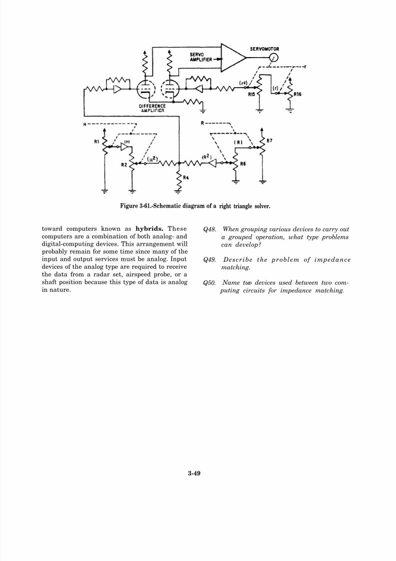
8/14/2019 US Navy Course NAVEDTRA 14028 - Aviation Electronics Technician-Basic
http://slidepdf.com/reader/full/us-navy-course-navedtra-14028-aviation-electronics-technician-basic 160/415
Figure 3-61.-Schematic diagram of a
toward computers known as hybrids. These Q48.computers are a combination of both analog- anddigital-computing devices. This arrangement willprobably remain for some time since many of theinput and output services must be analog. Input Q49.devices of the analog type are required to receive
the data from a radar set, airspeed probe, or a
shaft position because this type of data is analog Q50.in nature.
right triangle solver.
When grouping various devices to carry out
a grouped operation, what type problems
can develop?
Describe the problem of impedance
matching.
Name two devices used between two com-
puting circuits for impedance matching.
3-49

8/14/2019 US Navy Course NAVEDTRA 14028 - Aviation Electronics Technician-Basic
http://slidepdf.com/reader/full/us-navy-course-navedtra-14028-aviation-electronics-technician-basic 161/415
3-50

8/14/2019 US Navy Course NAVEDTRA 14028 - Aviation Electronics Technician-Basic
http://slidepdf.com/reader/full/us-navy-course-navedtra-14028-aviation-electronics-technician-basic 162/415
CHAPTER 4
DIGITAL COMPUTERS
4-1
This chapter has been deleted. For information on digital computers, refer to
Nonresident Training Course (NRTC) Navy Electricity and Electronics Training
Series (NEETS) Module 22, NAVEDTRA 14194. For information on number
systems and logic, refer to Nonresident Training Course (NRTC) Navy Electricityand Electronics Training Series (NEETS) Module 13, NAVEDTRA 14185.

8/14/2019 US Navy Course NAVEDTRA 14028 - Aviation Electronics Technician-Basic
http://slidepdf.com/reader/full/us-navy-course-navedtra-14028-aviation-electronics-technician-basic 163/415

8/14/2019 US Navy Course NAVEDTRA 14028 - Aviation Electronics Technician-Basic
http://slidepdf.com/reader/full/us-navy-course-navedtra-14028-aviation-electronics-technician-basic 164/415
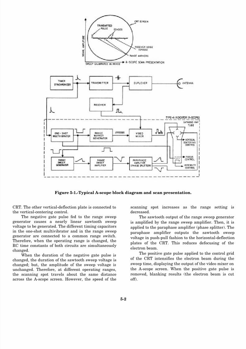
8/14/2019 US Navy Course NAVEDTRA 14028 - Aviation Electronics Technician-Basic
http://slidepdf.com/reader/full/us-navy-course-navedtra-14028-aviation-electronics-technician-basic 165/415
Figure 5-1.-Typical A-scope block diagram and scan presentation.
CRT. The other vertical-deflection plate is connected tothe vertical-centering control.
The negative gate pulse fed to the range sweepgenerator causes a nearly linear sawtooth sweep
voltage to be generated. The different timing capacitors
in the one-shot multivibrator and in the range sweepgenerator are connected to a common range switch.Therefore, when the operating range is changed, the
RC time constants of both circuits are simultaneouslychanged.
When the duration of the negative gate pulse is
changed, the duration of the sawtooth sweep voltage ischanged; but, the amplitude of the sweep voltage isunchanged. Therefore, at different operating ranges,
the scanning spot travels about the same distanceacross the A-scope screen. However, the speed of the
scanning spot increases as the range setting
decreased.
The sawtooth output of the range sweep generat
is amplified by the range sweep amplifier. Then, it
applied to the paraphase amplifier (phase splitter). Th
paraphase amplifier outputs the sawtooth swe
voltage in push-pull fashion to the horizontal-deflecti
plates of the CRT. This reduces defocusing of thelectron beam.
The positive gate pulse applied to the control gr
of the CRT intensifies the electron beam during th
sweep time, displaying the output of the video mixer o
the A-scope screen. When the positive gate pulse
removed, blanking results (the electron beam is cu
off ).
5-2
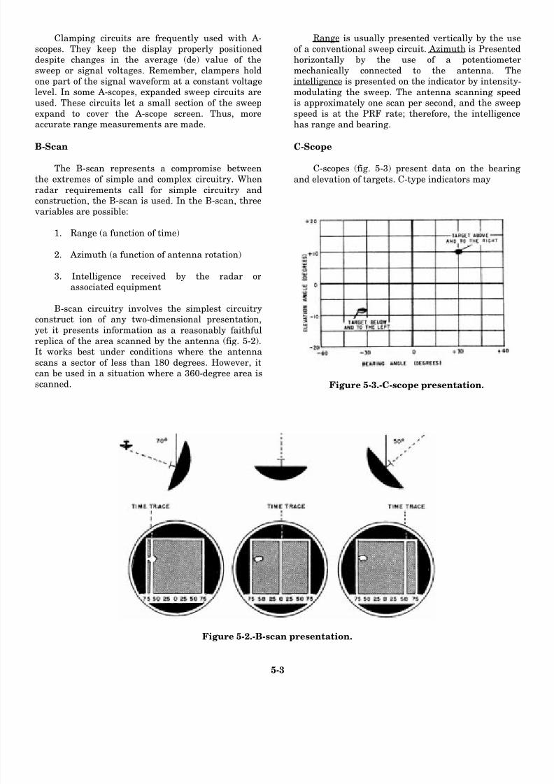
8/14/2019 US Navy Course NAVEDTRA 14028 - Aviation Electronics Technician-Basic
http://slidepdf.com/reader/full/us-navy-course-navedtra-14028-aviation-electronics-technician-basic 166/415
Clamping circuits are frequently used with A-scopes. They keep the display properly positioneddespite changes in the average (de) value of the
sweep or signal voltages. Remember, clampers holdone part of the signal waveform at a constant voltagelevel. In some A-scopes, expanded sweep circuits are
used. These circuits let a small section of the sweepexpand to cover the A-scope screen. Thus, moreaccurate range measurements are made.
B-Scan
The B-scan represents a compromise betweenthe extremes of simple and complex circuitry. When
radar requirements call for simple circuitry andconstruction, the B-scan is used. In the B-scan, three
variables are possible:
1. Range (a function of time)
2. Azimuth (a function of antenna rotation)
3. Intelligence received by the radar orassociated equipment
B-scan circuitry involves the simplest circuitryconstruct ion of any two-dimensional presentation,yet it presents information as a reasonably faithfulreplica of the area scanned by the antenna (fig. 5-2).It works best under conditions where the antenna
scans a sector of less than 180 degrees. However, itcan be used in a situation where a 360-degree area isscanned.
Range is usually presented vertically by the useof a conventional sweep circuit. Azimuth is Presentedhorizontally by the use of a potentiometer
mechanically connected to the antenna. Theintelligence is presented on the indicator by intensity
modulating the sweep. The antenna scanning speedis approximately one scan per second, and the sweepspeed is at the PRF rate; therefore, the intelligence
has range and bearing.
C-Scope
C-scopes (fig. 5-3) present data on the bearing
and elevation of targets. C-type indicators may
Figure 5-3.-C-scope presentation.
Figure 5-2.-B-scan presentation.
5-3

8/14/2019 US Navy Course NAVEDTRA 14028 - Aviation Electronics Technician-Basic
http://slidepdf.com/reader/full/us-navy-course-navedtra-14028-aviation-electronics-technician-basic 167/415
Figure 5-4.—PPI presentation.
5-4
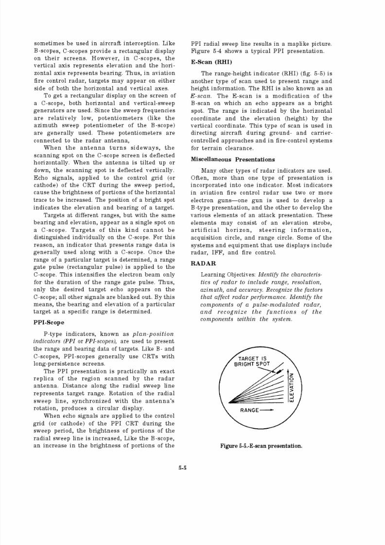
8/14/2019 US Navy Course NAVEDTRA 14028 - Aviation Electronics Technician-Basic
http://slidepdf.com/reader/full/us-navy-course-navedtra-14028-aviation-electronics-technician-basic 168/415
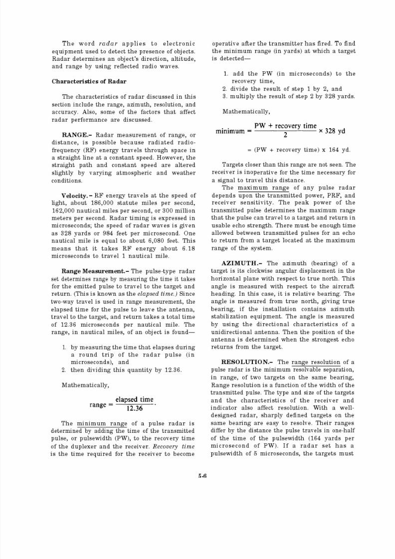
8/14/2019 US Navy Course NAVEDTRA 14028 - Aviation Electronics Technician-Basic
http://slidepdf.com/reader/full/us-navy-course-navedtra-14028-aviation-electronics-technician-basic 169/415

8/14/2019 US Navy Course NAVEDTRA 14028 - Aviation Electronics Technician-Basic
http://slidepdf.com/reader/full/us-navy-course-navedtra-14028-aviation-electronics-technician-basic 170/415
be separated by more than 820 yards before they
could appear as two pips on the scope. Theformulas for range resolution and minimum target
separation are given below:
range resolution = PW x 328 yd
minimum target separation = PW x 164 yd
Azimuth resolutionis the ability to separate
targets at the same range but on different
bearings. Azimuth resolution is a function of the
antenna beamwidth and the range of the targets.The antenna beamwidth is the angular distance
between the half-power points of an antenna’s
radiation pattern. Two targets at the same range
appear as one target instead of two. They must
be separated by at least one beamwidth todistinguish between them. Strong multiple targets
appearing as one target are resolved in azimuth
(bearing) by reducing the gain of the receiver.
ACCURACY.– The accuracy of a radar is a
measure of its ability to determine the correct
range and bearing of a target. To determine the
degree of accuracy in azimuth, the effective
beamwidth is narrowed. On a PPI scope, the echo
begins to appear when energy in the edge of the
beam first strikes the target. The echo is strongestas the axis of the beam crosses the target. The echo
continues to appear on the scope as long as anypart of the beam strikes the target. The target
appears wider on the PPI than it actually is. Therelative accuracy of the presentation depends on
the width of the radar beam and range of the
target.
The true range of a target is the actualdistance between the target and the radar set(fig. 5-6). In airborne radar, the true range is
called slant range. The term slant range indicates
that the range measurement includes the effect of a difference in altitude.
The hor izon tal ran ge of a target is a
straight-line distance (fig. 5-6) along an imaginaryline parallel to the earth’s surface. This concept
is important. An airborne target, or the observer’s
aircraft, only needs to travel the distancerepresented by its horizontal range to reach a
position directly over its target. For example, anaircraft at a slant range of 10 miles at an altitudeof 36,000 feet above the radar observer’s aircrafthas a horizontal range of 8 miles.
The timing sequence of a radar range-indicating device starts at the same instant that
the transmitter starts operation. Therefore, with
airborne surface-search radar, the first targets seenare those directly beneath the aircraft. However,
Figure 5-6.-Slant range versus horizontal range.
5-7

8/14/2019 US Navy Course NAVEDTRA 14028 - Aviation Electronics Technician-Basic
http://slidepdf.com/reader/full/us-navy-course-navedtra-14028-aviation-electronics-technician-basic 171/415
on the PPI scope, there is a hole in the middle of thepicture (fig. 5-7), with a minimum radiuscorresponding to the altitude of the aircraft. The hole
is known as the altitude ring. Objects directlybeneath the aircraft appear on the scope at a distanceequal to the distance between the aircraft andground.
Factors Affecting Radar
Many factors affect radar performance; the
principal one is maintenance. Keeping the
equipment operating at peak efficiency affects theoverall capabilities and limitations of the radar. A
second factor is the radar operator’s knowledge of
the equipment. This knowledge must include themaximum and minimum ranges at which theoperator can expect to pick up various targets, the
range and bearing accuracy of the gear, and therange and bearing resolution. If the radar is a heightfinder, the operator must know the altitude
determination accuracy and the altitude resolutionSome of the factors that affect radar are coveredbelow. For more detailed information, you shoul
refer to the maintenance instruction manual (MIMfor each radar.
PEAK POWER.—The peak power of a radar is
its useful power. The range capabilities of the radar
increase with an increase in peak power.
Figure 5-7.-Effect of altitude on radar. (A) Radar tilted down; (B) radar with zero tilt.
5-8
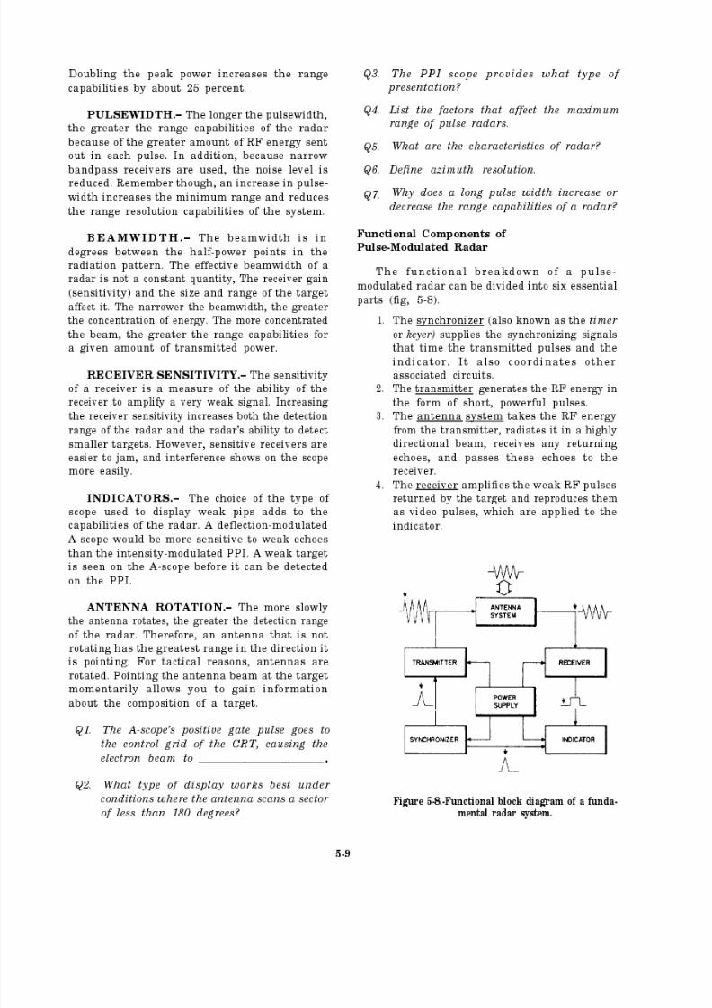
8/14/2019 US Navy Course NAVEDTRA 14028 - Aviation Electronics Technician-Basic
http://slidepdf.com/reader/full/us-navy-course-navedtra-14028-aviation-electronics-technician-basic 172/415
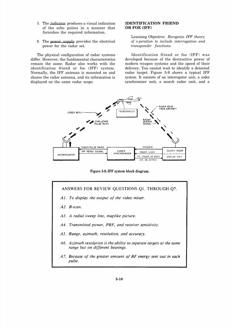
8/14/2019 US Navy Course NAVEDTRA 14028 - Aviation Electronics Technician-Basic
http://slidepdf.com/reader/full/us-navy-course-navedtra-14028-aviation-electronics-technician-basic 173/415
5.
6.
The indicator produces a visual indication
of the echo pulses in a manner thatfurnishes the required information.
The power supply provides the electrical
power for the radar set.
The physical configuration of radar systems
differ. However, the fundamental characteristicsremain the same. Radar also works with the
identification friend or foe (IFF) system.Normally, the IFF antenna is mounted on and
shares the radar antenna, and its information is
displayed on the same radar scope.
IDENTIFICATION FRIENDOR FOE (IFF)
Learning Objective: Recognize IFF theory
of o peration to include interrogation and
transponder functions.
Identification friend or foe (IFF) wasdeveloped because of the destructive power of modern weapon systems and the speed of their
delivery. You cannot wait to identify a detectedradar target. Figure 5-9 shows a typical IFF
system. It consists of an interrogator unit, a coder
synchronizer unit, a search radar unit, and a
Figure 5-9.-IFF system block diagram.
5-10

8/14/2019 US Navy Course NAVEDTRA 14028 - Aviation Electronics Technician-Basic
http://slidepdf.com/reader/full/us-navy-course-navedtra-14028-aviation-electronics-technician-basic 174/415
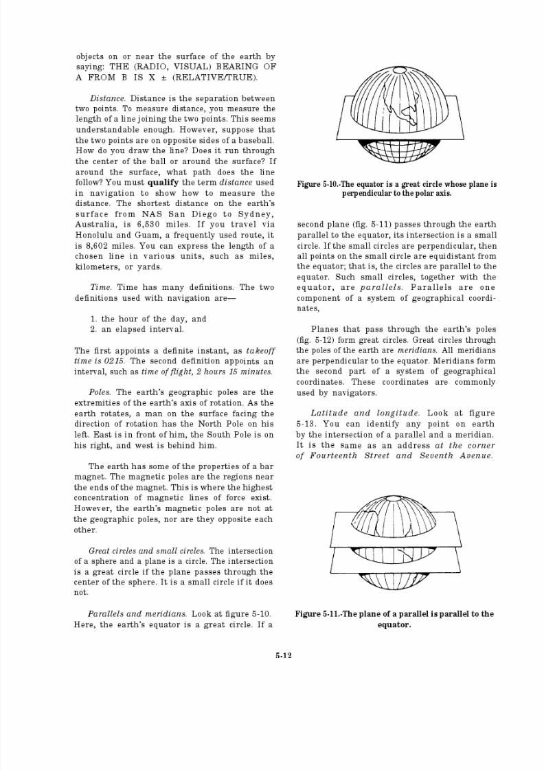
8/14/2019 US Navy Course NAVEDTRA 14028 - Aviation Electronics Technician-Basic
http://slidepdf.com/reader/full/us-navy-course-navedtra-14028-aviation-electronics-technician-basic 175/415
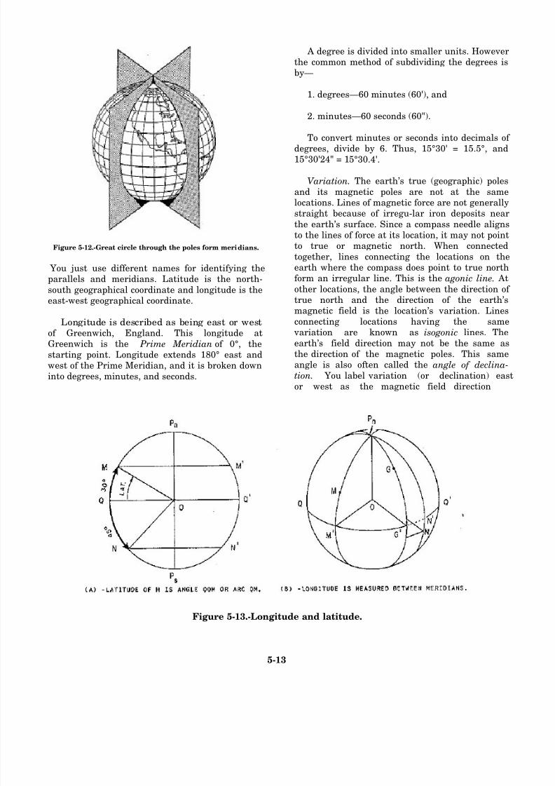
8/14/2019 US Navy Course NAVEDTRA 14028 - Aviation Electronics Technician-Basic
http://slidepdf.com/reader/full/us-navy-course-navedtra-14028-aviation-electronics-technician-basic 176/415
Figure 5-12.-Great circle through the poles form meridians.
You just use different names for identifying the
parallels and meridians. Latitude is the north-south geographical coordinate and longitude is theeast-west geographical coordinate.
Longitude is described as being east or westof Greenwich, England. This longitude atGreenwich is the Prime Meridian of 0°, thestarting point. Longitude extends 180° east andwest of the Prime Meridian, and it is broken downinto degrees, minutes, and seconds.
A degree is divided into smaller units. Howeverthe common method of subdividing the degrees isby—
1. degrees—60 minutes (60'), and
2. minutes—60 seconds (60").
To convert minutes or seconds into decimals of degrees, divide by 6. Thus, 15°30' = 15.5°, and15°30'24" = 15°30.4'.
Variation. The earth’s true (geographic) poles
and its magnetic poles are not at the samelocations. Lines of magnetic force are not generallystraight because of irregu-lar iron deposits near
the earth’s surface. Since a compass needle alignsto the lines of force at its location, it may not pointto true or magnetic north. When connected
together, lines connecting the locations on theearth where the compass does point to true north
form an irregular line. This is the agonic line. Atother locations, the angle between the direction of true north and the direction of the earth’smagnetic field is the location’s variation. Linesconnecting locations having the same
variation are known as isogonic lines. The
earth’s field direction may not be the same asthe direction of the magnetic poles. This sameangle is also often called the angle of declina-tion. You label variation (or declination) eastor west as the magnetic field direction
Figure 5-13.-Longitude and latitude.
5-13
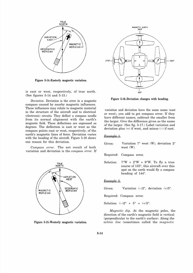
8/14/2019 US Navy Course NAVEDTRA 14028 - Aviation Electronics Technician-Basic
http://slidepdf.com/reader/full/us-navy-course-navedtra-14028-aviation-electronics-technician-basic 177/415
Figure 5-14.-Easterly magnetic variation.
is east or west, respectively, of true north.
(See figures 5-14 and 5-15.)
Deviation. Deviation is the error in a magneticcompass caused by nearby magnetic influences.These influences may relate to magnetic material
in the structure of the aircraft and to electrical
(electronic) circuits. They deflect a compass needlefrom its normal alignment with the earth’s
magnetic field. These deflections are expressed asdegrees. The deflection is east or west as the
compass points east or west, respectively, of the
earth’s magnetic lines of force. Deviation varieswith the heading of the aircraft. Figure 5-16 shows
one reason for this deviation.
Compass error. The net result of both
variation and deviation is the compass error. If
Figure 5-15.-Westerly magnetic variation.
Figure 5-16.-Deviation changes with heading.
variation and deviation have the same name (east
or west), you add to get compass error. If they
have different names, subtract the smaller from
the larger. Give the difference given as the name
of the larger. (See fig. 5-17.) Label variation anddeviation plus (+) if west, and minus (–) if east.
Example 1.
Given:
Required:
Solution:
Variation 7° west (W), deviation 2°west (W).
Compass error.
7°W + 2°W = 9°W. To fly a true
course of 135°, this aircraft over thisspot on the earth would fly a compassheading of 144°.
Example 2.
Given: Variation (–)2°, deviation (+)5°.
Required: Compass error.
Solution: (–)2° + 5° = (+)3°.
Magnetic dip. At the magnetic poles, the
direction of the earth’s magnetic field is vertical
(perpendicular to the earth’s surface). Along theaclinic line (sometimes called the magnetic
5-14
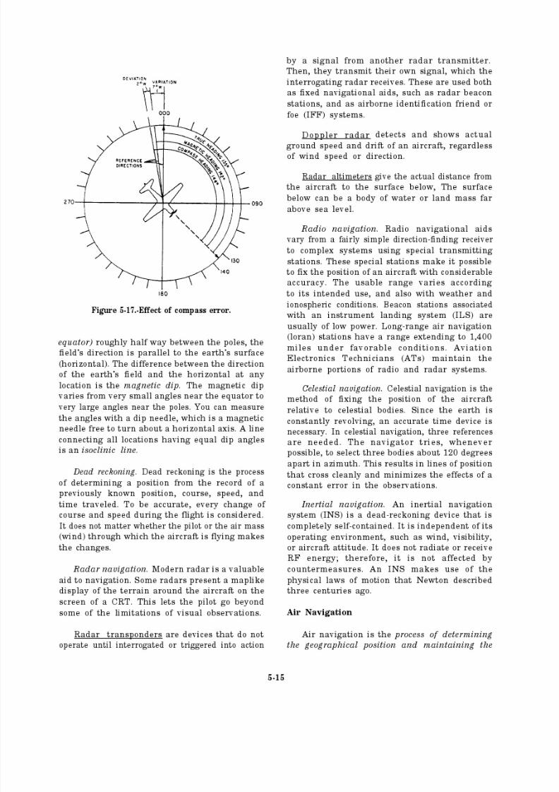
8/14/2019 US Navy Course NAVEDTRA 14028 - Aviation Electronics Technician-Basic
http://slidepdf.com/reader/full/us-navy-course-navedtra-14028-aviation-electronics-technician-basic 178/415
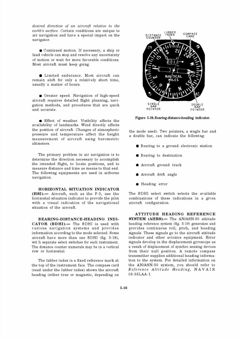
8/14/2019 US Navy Course NAVEDTRA 14028 - Aviation Electronics Technician-Basic
http://slidepdf.com/reader/full/us-navy-course-navedtra-14028-aviation-electronics-technician-basic 179/415
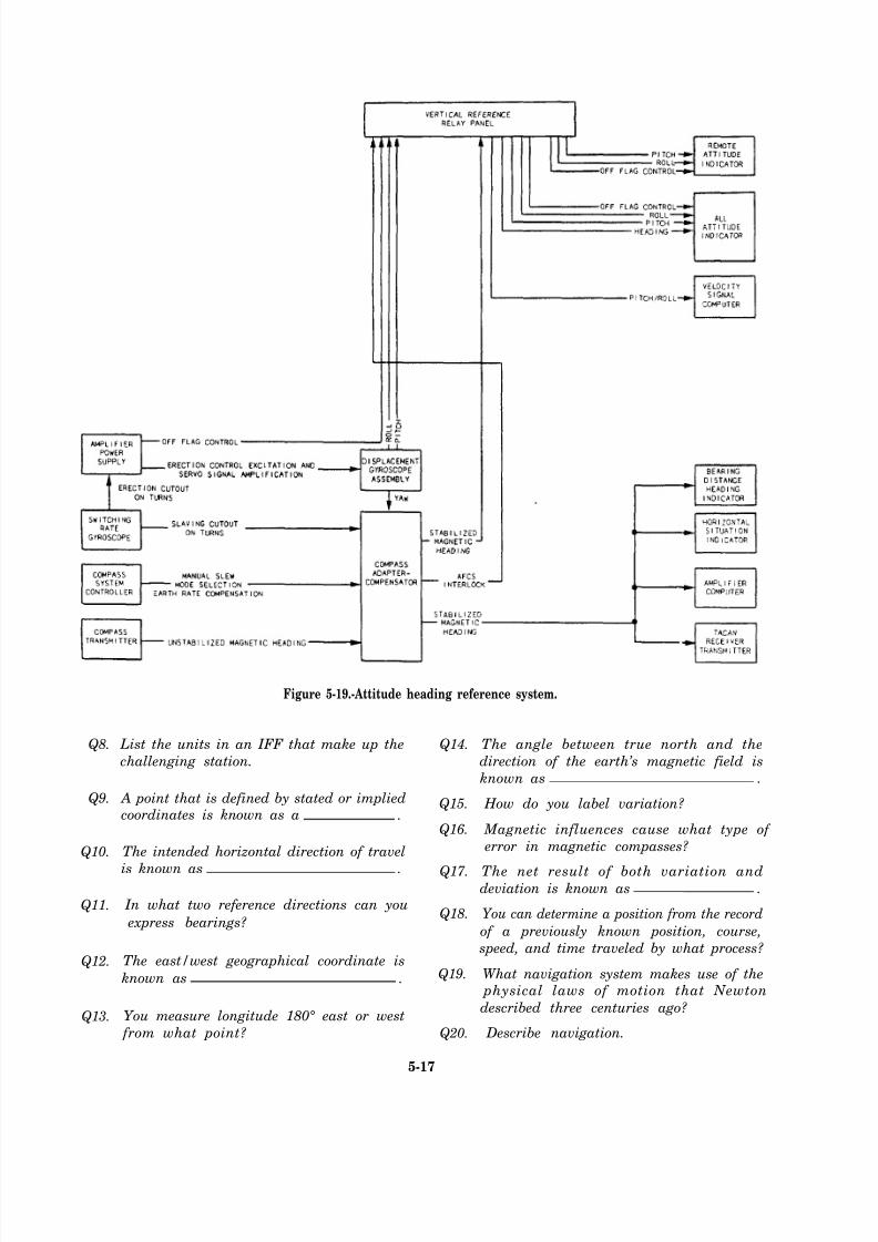
8/14/2019 US Navy Course NAVEDTRA 14028 - Aviation Electronics Technician-Basic
http://slidepdf.com/reader/full/us-navy-course-navedtra-14028-aviation-electronics-technician-basic 180/415
Q8.
Q9.
Q10.
Q11.
Q12.
Q13.
Figure 5-19.-Attitude heading reference system.
List the units in an IFF that make up the Q14.
challenging station.
A point that is defined by stated or implied Q15.coordinates is known as a .
Q16.
The intended horizontal direction of travel
is known as . Q17.
In what two reference directions can you
express bearings?Q18.
The east/west geographical coordinate is
known as . Q19.
You measure longitude 180° east or west
from what point? Q20.
5-17
The angle between true north and the
direction of the earth’s magnetic field is
known as .
How do you label variation?
Magnetic influences cause what type of
error in magnetic compasses?
The net result of both variation anddeviation is known as .
You can determine a position from the record
of a previously known position, course,
speed, and time traveled by what process?
What navigation system makes use of the physical laws of motion that Newton
described three centuries ago?
Describe navigation.
8/14/2019 US Navy Course NAVEDTRA 14028 - Aviation Electronics Technician-Basic
http://slidepdf.com/reader/full/us-navy-course-navedtra-14028-aviation-electronics-technician-basic 181/415
Inertial Navigation System
The inertial navigation system (INS) is
sometimes maintained by personnel in the Aviation Electronics Technician (AT) rating.
Some squadrons have an integrated weapons team(IWT). It is composed of the three
avionics/armament division (work center 200)ratings—AT, AO, and AE.
Navigation is defined as the process of
directing a vehicle from one point to another.Navigation can be divided into two basic
categories—position fixing and dead reckoning.
In position fixing, you determine positionrelative to positions of known objects such as stars
and landmarks. The most common example of
navigation by position fixing is celestial navi-
gation. Loran is another example of navigationby periodic position fixes. Except for INS,
navigation systems rely on some information thatis external to the vehicle to solve its navigationalproblem.
Dead reckoning, the second category, is theprocess of estimating your position from the
following known information:
Previous position
Course
Speed
Time elapsed
Two examples of navigation by dead reckoning
are Doppler radar and inertial navigation systems.
BASIC PRINCIPLES.– The operatingprinciple of the inertial navigation system (INS)
ANSWERS FOR REVIEW QUESTIONS Q8. THROUGH Q20.
A8. The interrogator, synchronizer, and radar.
A9. Position.
A10. Course.
A11. True north or the direction the aircraft is pointing.
A12. Longitude.
A1 3. Prime Meridian, 0 degree in Greenwich, England.
A14. Variation.
A15. You label variation east or west as the magnetic field direction
is east or west, respectively, of true north.
A16. Deviation.
A17. Compass error.
A18. Dead reckoning.
A19. Inertial navigation.
A20. Air navigation is the process of determining the geographical
position and maintaining the desired direction of an aircraft
relative to the earth’s surface.
5-18
8/14/2019 US Navy Course NAVEDTRA 14028 - Aviation Electronics Technician-Basic
http://slidepdf.com/reader/full/us-navy-course-navedtra-14028-aviation-electronics-technician-basic 182/415
8/14/2019 US Navy Course NAVEDTRA 14028 - Aviation Electronics Technician-Basic
http://slidepdf.com/reader/full/us-navy-course-navedtra-14028-aviation-electronics-technician-basic 183/415
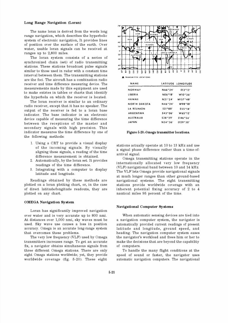
8/14/2019 US Navy Course NAVEDTRA 14028 - Aviation Electronics Technician-Basic
http://slidepdf.com/reader/full/us-navy-course-navedtra-14028-aviation-electronics-technician-basic 184/415
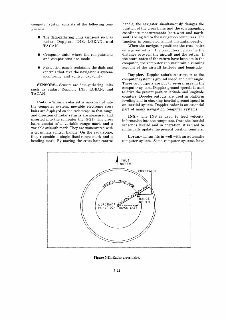
8/14/2019 US Navy Course NAVEDTRA 14028 - Aviation Electronics Technician-Basic
http://slidepdf.com/reader/full/us-navy-course-navedtra-14028-aviation-electronics-technician-basic 185/415
computer system consists of the following com- handle, the navigator simultaneously changes the
ponents: position of the cross hairs and the corresponding
coordinate measurements (east-west and north-
The data-gathering units (sensors) such as south) being fed to the navigation computers. The
radar, Doppler, INS, LORAN, and function is completed almost instantaneously.
TACAN When the navigator positions the cross hairs
on a given return, the computers determine the
Computer units where the computations distance between the aircraft and the return. If and comparisons are made the coordinates of the return have been set in thecomputer, the computer can maintain a running
Navigation panels containing the dials and account of the aircraft latitude and longitude.
controls that give the navigator a system-monitoring and control capability
SENSORS.– Sensors are data-gathering units
such as radar, Doppler, INS, LORAN, andTACAN.
Radar.– When a radar set is incorporated intothe computer system, movable electronic cross
hairs are displayed on the radarscope so that rangeand direction of radar returns are measured andinserted into the computer (fig. 5-21). The crosshairs consist of a variable range mark and a
variable azimuth mark. They are maneuvered with
a cross hair control handle. On the radarscope,they resemble a single fixed-range mark and aheading mark. By moving the cross hair control
Doppler.– Doppler radar’s contribution to the
computer system is ground speed and drift angle.These two outputs are put to several uses in the
computer system. Doppler ground speeds is used
to drive the present position latitude and longitudecounters. Doppler outputs are used in platformleveling and in checking inertial ground speed in
an inertial system. Doppler radar is an essentialpart of many navigation computer systems.
INS.– The INS is used to feed velocityinformation into the computers. Once the inertial
sensor is leveled and in operation, it is used tocontinually update the present position counters.
Loran.– Loran fits in well with an automatic
computer system. Some computer systems have
Figure 5-21.-Radar cross hairs.
5-22

8/14/2019 US Navy Course NAVEDTRA 14028 - Aviation Electronics Technician-Basic
http://slidepdf.com/reader/full/us-navy-course-navedtra-14028-aviation-electronics-technician-basic 186/415
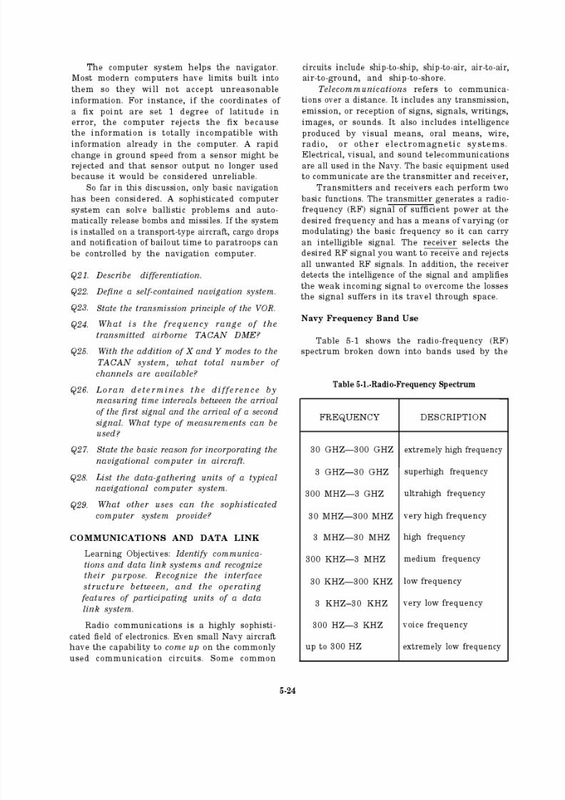
8/14/2019 US Navy Course NAVEDTRA 14028 - Aviation Electronics Technician-Basic
http://slidepdf.com/reader/full/us-navy-course-navedtra-14028-aviation-electronics-technician-basic 187/415
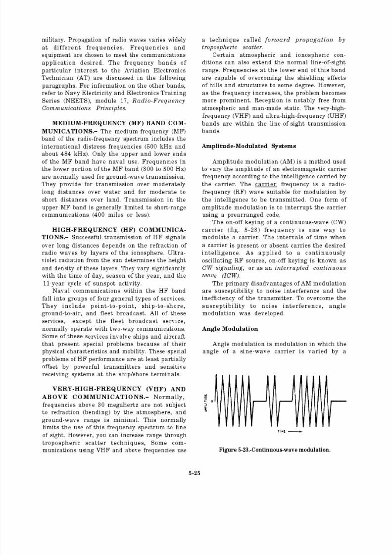
8/14/2019 US Navy Course NAVEDTRA 14028 - Aviation Electronics Technician-Basic
http://slidepdf.com/reader/full/us-navy-course-navedtra-14028-aviation-electronics-technician-basic 188/415
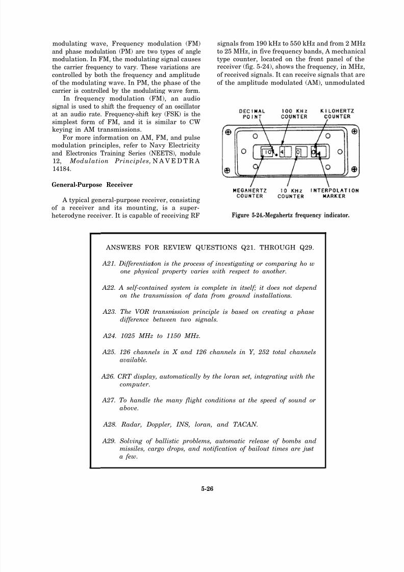
8/14/2019 US Navy Course NAVEDTRA 14028 - Aviation Electronics Technician-Basic
http://slidepdf.com/reader/full/us-navy-course-navedtra-14028-aviation-electronics-technician-basic 189/415
modulating wave, Frequency modulation (FM) signals from 190 kHz to 550 kHz and from 2 MHz
and phase modulation (PM) are two types of angle to 25 MHz, in five frequency bands, A mechanical
modulation. In FM, the modulating signal causes type counter, located on the front panel of the
the carrier frequency to vary. These variations are receiver (fig. 5-24), shows the frequency, in MHz,
controlled by both the frequency and amplitude of received signals. It can receive signals that are
of the modulating wave. In PM, the phase of the of the amplitude modulated (AM), unmodulated
carrier is controlled by the modulating wave form.
In frequency modulation (FM), an audiosignal is used to shift the frequency of an oscillatorat an audio rate. Frequency-shift key (FSK) is the
simplest form of FM, and it is similar to CWkeying in AM transmissions.
For more information on AM, FM, and pulsemodulation principles, refer to Navy Electricity
and Electronics Training Series (NEETS), module12, Modulation Principles, N A V E D T R A
14184.
General-Purpose Receiver
A typical general-purpose receiver, consistingof a receiver and its mounting, is a super-heterodyne receiver. It is capable of receiving RF Figure 5-24.-Megahertz frequency indicator.
ANSWERS FOR REVIEW QUESTIONS Q21. THROUGH Q29.
A21. Differentiation is the process of investigating or comparing ho wone physical property varies with respect to another.
A22. A self-contained system is complete in itself; it does not depend
on the transmission of data from ground installations.
A23. The VOR transmission principle is based on creating a phasedifference between two signals.
A24. 1025 MHz to 1150 MHz.
A25. 126 channels in X and 126 channels in Y, 252 total channels
available.
A26. CRT display, automatically by the loran set, integrating with the
computer.
A27. To handle the many flight conditions at the speed of sound orabove.
A28. Radar, Doppler, INS, loran, and TACAN.
A29. Solving of ballistic problems, automatic release of bombs andmissiles, cargo drops, and notification of bailout times are just
a few.
5-26
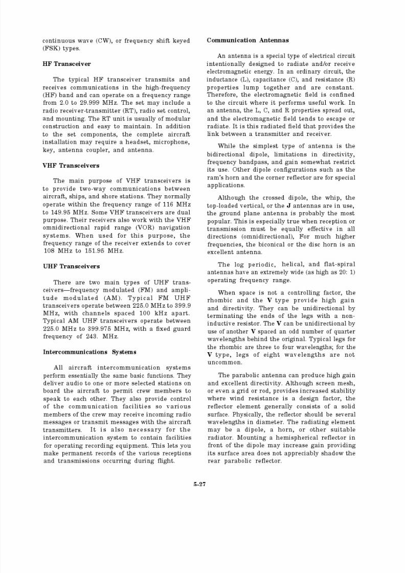
8/14/2019 US Navy Course NAVEDTRA 14028 - Aviation Electronics Technician-Basic
http://slidepdf.com/reader/full/us-navy-course-navedtra-14028-aviation-electronics-technician-basic 190/415
8/14/2019 US Navy Course NAVEDTRA 14028 - Aviation Electronics Technician-Basic
http://slidepdf.com/reader/full/us-navy-course-navedtra-14028-aviation-electronics-technician-basic 191/415
8/14/2019 US Navy Course NAVEDTRA 14028 - Aviation Electronics Technician-Basic
http://slidepdf.com/reader/full/us-navy-course-navedtra-14028-aviation-electronics-technician-basic 192/415
8/14/2019 US Navy Course NAVEDTRA 14028 - Aviation Electronics Technician-Basic
http://slidepdf.com/reader/full/us-navy-course-navedtra-14028-aviation-electronics-technician-basic 193/415
8/14/2019 US Navy Course NAVEDTRA 14028 - Aviation Electronics Technician-Basic
http://slidepdf.com/reader/full/us-navy-course-navedtra-14028-aviation-electronics-technician-basic 194/415
8/14/2019 US Navy Course NAVEDTRA 14028 - Aviation Electronics Technician-Basic
http://slidepdf.com/reader/full/us-navy-course-navedtra-14028-aviation-electronics-technician-basic 195/415
DICASS sonobuoy. A CASS sonobuoy,
equipped with a directional hydrophone, is adirectional commandable sonobuoy (DICASS). A DICASS sonobuoy lets the aircraft acoustic
analysis equipment determine both range andbearing to the target with a single sonobuoy.DICASS sonobuoys are replacing the older RO
and CASS sonobuoys.
SPECIAL-PURPOSE SONOBUOYS.–
Currently there are two categories of special-purpose sonobuoys in use by the fleet—the
bathythermobuoy (BTS), and the Down-Link
Communication (DLC) special-purpose sonobuoys.
These sonobuoys are NOT for use in sub-marine detection or localization.
Bathythermobuoy. The bathythermobuoy(BTS) measures the water temperature versus
depth. The time of descent of a temperature probedetermines the water depth. Once the BTS entersthe water, this probe (fig. 5-25) descendsautomatically at a constant 5 feet per second.
The probe uses a thermistor, a temperature-dependent electronic component, to measure the
temperature. The electrical output of the probe
goes to a voltage-controlled oscillator, whose
output signal frequency modulates the sonobuoytransmitter. The frequency of the transmit signal,which is recovered at the sonobuoy receiver in the
aircraft, is linearly proportional to water
temperature. The water temperature and depthare recorded on graph paper that is visible to the
ASW operator.
DLC. The down-link communition (DLC)
buoys are for communication between air-craft and submarines. The DLC buoy is not com-manded and provides down-link communications
only by a preselected code.
Sonobuoy Receivers
The sonobuoy receiver has many functions.
It receives RF signals from deployed sonobuoys,
ANSWERS FOR REVIEW QUESTIONS Q30. THROUGH Q37.
A30. Module 17.
A31. UHF and VHF.
A32. Module 12, Modulation Principles.
A33. Their receivers also work with VHF and VOR.
A34. The biconical or disc horn.
A35. Active EC M.
A36. The science of motion of projectiles.
A37. The curve o f a projectile describes in space as it travels to the
target.
5-32

8/14/2019 US Navy Course NAVEDTRA 14028 - Aviation Electronics Technician-Basic
http://slidepdf.com/reader/full/us-navy-course-navedtra-14028-aviation-electronics-technician-basic 196/415
Figure 5-25.-Bathythermograph sonobuoy deployment.
detects intelligence on the signals, providesintelligence to various onboard equipment foracoustic analysis and recording and for navigatingor navigation purposes.
SONOBUOY RECEIVER SET.– One com-monly used sonobuoy receiver set includes 31
radio receivers that receive FM-modulated signals
in the VHF range. Thus, simultaneous reception,demodulation (detection), and audio output of up
to 31 RF channels are possible. These channels
may each be any one of 31 preselected channels.Each audio output provides two levels—high
audio and standard audio.
The equipment is primarily for (but not limited
to) installation in either fixed- or rotary-wing
aircraft. Although capable of being an inde-
pendent operating unit, normally, the equipmentis used with some combination of several types
of sonobuoys and a signal processor.
Newer sonobuoy receiver groups provide thecapability of simultaneously receiving 20
sonobuoy signals. To accomplish this they use
20 subassemblies. Each subassembly may be
independently and automatically tuned to any1 of 99 sonobuoy RF channels now in use, and
those that are in development for futuredeployment.
5-33
8/14/2019 US Navy Course NAVEDTRA 14028 - Aviation Electronics Technician-Basic
http://slidepdf.com/reader/full/us-navy-course-navedtra-14028-aviation-electronics-technician-basic 197/415
8/14/2019 US Navy Course NAVEDTRA 14028 - Aviation Electronics Technician-Basic
http://slidepdf.com/reader/full/us-navy-course-navedtra-14028-aviation-electronics-technician-basic 198/415

8/14/2019 US Navy Course NAVEDTRA 14028 - Aviation Electronics Technician-Basic
http://slidepdf.com/reader/full/us-navy-course-navedtra-14028-aviation-electronics-technician-basic 199/415
8/14/2019 US Navy Course NAVEDTRA 14028 - Aviation Electronics Technician-Basic
http://slidepdf.com/reader/full/us-navy-course-navedtra-14028-aviation-electronics-technician-basic 200/415
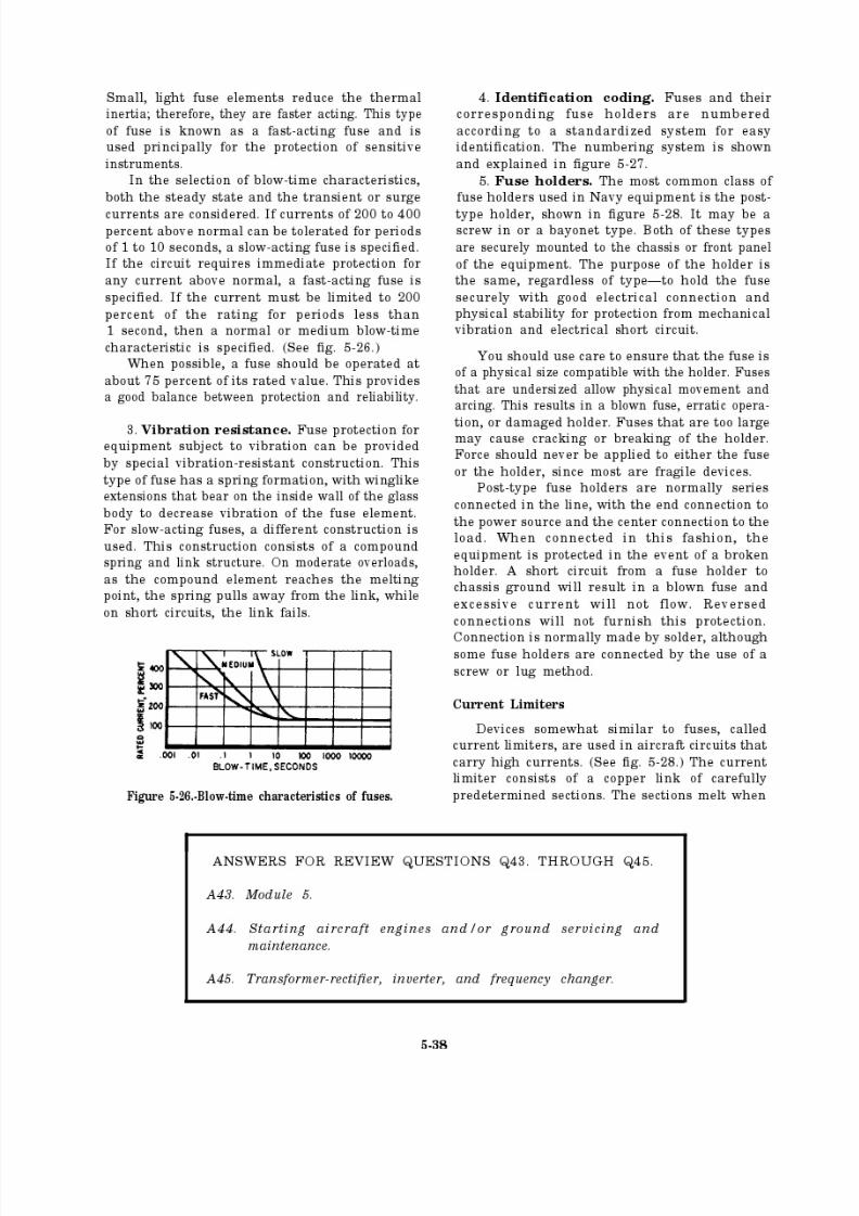
8/14/2019 US Navy Course NAVEDTRA 14028 - Aviation Electronics Technician-Basic
http://slidepdf.com/reader/full/us-navy-course-navedtra-14028-aviation-electronics-technician-basic 201/415

8/14/2019 US Navy Course NAVEDTRA 14028 - Aviation Electronics Technician-Basic
http://slidepdf.com/reader/full/us-navy-course-navedtra-14028-aviation-electronics-technician-basic 202/415
Figure 5-27.-Identification coding: (A) fuses; (B) fuse holders.
Figure 5-28.-Example of aircraft fuses and holders.
abnormally high currents start to flow. Themelting sections have a high-arc resistance to keep
the circuit current within the capacity of thelimiter. If the excessive current is only a temporarysurge, the melting ceases, and the circuit continuesto operate as if no abnormal current had beenpresent. Repeated applications of excessive
current or uninterrupted application for a period
of several seconds melt through the sections andcause the limiter to function in the same manneras a fuse.
Circuit Breakers
In modern naval aircraft, circuit breakers have
replaced fuses as the circuit protection devices for
most of the wires and cables making up the
electrical system. The circuit breaker is designed
to open the circuit under short-circuit or overload
conditions without injury to itself. Thus, itperforms the same function as the fuse, but it hasthe advantage of being reset and used again.Circuit breakers are rated in amperes and volts.
There are three basic types of circuit
breakers—thermal, magnetic, and thermomag-netic. The following discussion is slanted toward
the thermal type, because this type is more widely
used. Circuit breakers are divided into three
categories—the push-button reset type, the toggletype, and the automatic reset type (sometimes
called a circuit protector).The push-button reset type (fig. 5-29) consists
of a bimetallic, thermally actuated, spring-loaded
Figure 5-29.-Thermal circuit breaker.
5-39

8/14/2019 US Navy Course NAVEDTRA 14028 - Aviation Electronics Technician-Basic
http://slidepdf.com/reader/full/us-navy-course-navedtra-14028-aviation-electronics-technician-basic 203/415
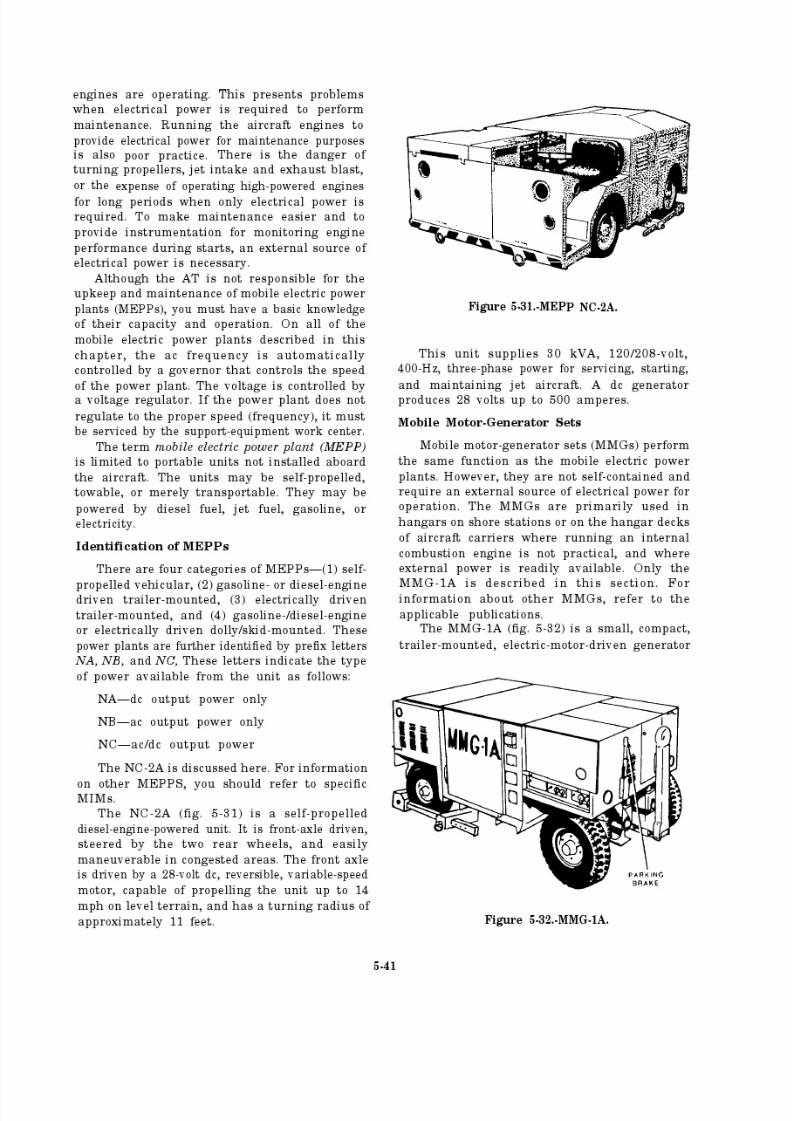
8/14/2019 US Navy Course NAVEDTRA 14028 - Aviation Electronics Technician-Basic
http://slidepdf.com/reader/full/us-navy-course-navedtra-14028-aviation-electronics-technician-basic 204/415

8/14/2019 US Navy Course NAVEDTRA 14028 - Aviation Electronics Technician-Basic
http://slidepdf.com/reader/full/us-navy-course-navedtra-14028-aviation-electronics-technician-basic 205/415
set, used to pro vide 115/200-volt, three-phase,400-Hz ac power for ground maintenance,
calibration, and support for various types of
aircraft systems and equipment. Operation oft heunit requires a three-phase, 60-Hz, 220- or440-volt ac external power source. The unit must
be towed or manually moved.
Additional Support Equipment
Other power systems and support equipmentsavailable to the AT include the deck-edge powersystem, the flight-line distribution system, and
ground-cooling equipment.
DECK-EDGE POWER.— The primary func-tion of the deck-edge electrical power systeminstalled on aircraft carriers is to provide a readily
accessible source of servicing and starting powerto aircraft at almost all locations on the carrier’s
flight and hangar decks.
FLIGHT-LINE ELECTRICAL DISTRIBU-TION SYSTEM.— The flight -line electrical distri-
bution system (FLEDS) is an electrical distribution
system for servicing aircraft on the flight line.Figure 5-33 shows the major parts of the FLEDS.
It consists of three-way junction boxes, inter-
connecting ramps, aircraft service point castings,
and aircraft connector plug assemblies. The totalsystem capability is 24 aircraft. (See fig. 5-33.)Each service point can service one aircraft with
115/200-volt, three-phase, 400-Hz power,
The FLEDS accepts power from a mobile elec-
trical power plant (MEPP) capable of supplying115/200-volt, three-phase, 400-Hz power. Power
is applied at the junction boxes and branches into
the service point castings to the aircraft connectorplug assemblies. The cables connecting the junc-tion boxes, service point castings, and aircraft
connector plugs are installed underneath theinterconnecting ramps for protection.
Figure 5-33.-FLEDS.
5-42
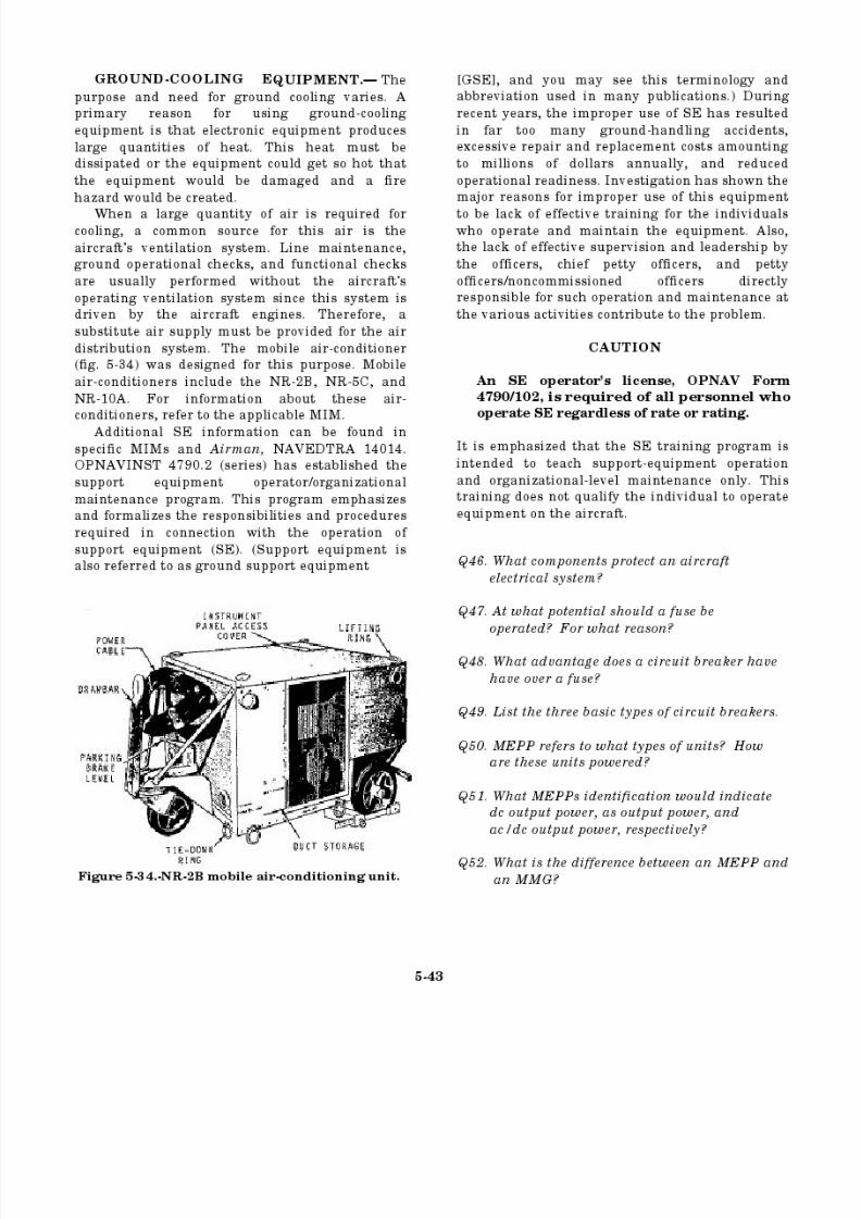
8/14/2019 US Navy Course NAVEDTRA 14028 - Aviation Electronics Technician-Basic
http://slidepdf.com/reader/full/us-navy-course-navedtra-14028-aviation-electronics-technician-basic 206/415
8/14/2019 US Navy Course NAVEDTRA 14028 - Aviation Electronics Technician-Basic
http://slidepdf.com/reader/full/us-navy-course-navedtra-14028-aviation-electronics-technician-basic 207/415
ANSWERS FOR REVIEW QUESTIONS Q46. THROUGH Q52.
A46.
A47.
A48.
A49.
A50.
A51.
A52.
Fuses, current limiters, and circuit breakers.
At about 75 percent of its rated value, it provides a good balance
between protection and reliability.
They can be reset and used again.
Thermal, magnetic, and thermomagnetic.
Portable units not installed aboard aircraft; they are powered
by either diesel fuel, jet fuel, gasoline, or electricity.
NA, NB, and NC.
MMGs are not self-contained and require an external electrical
power source for operation.
5-44
8/14/2019 US Navy Course NAVEDTRA 14028 - Aviation Electronics Technician-Basic
http://slidepdf.com/reader/full/us-navy-course-navedtra-14028-aviation-electronics-technician-basic 208/415
8/14/2019 US Navy Course NAVEDTRA 14028 - Aviation Electronics Technician-Basic
http://slidepdf.com/reader/full/us-navy-course-navedtra-14028-aviation-electronics-technician-basic 209/415
8/14/2019 US Navy Course NAVEDTRA 14028 - Aviation Electronics Technician-Basic
http://slidepdf.com/reader/full/us-navy-course-navedtra-14028-aviation-electronics-technician-basic 210/415
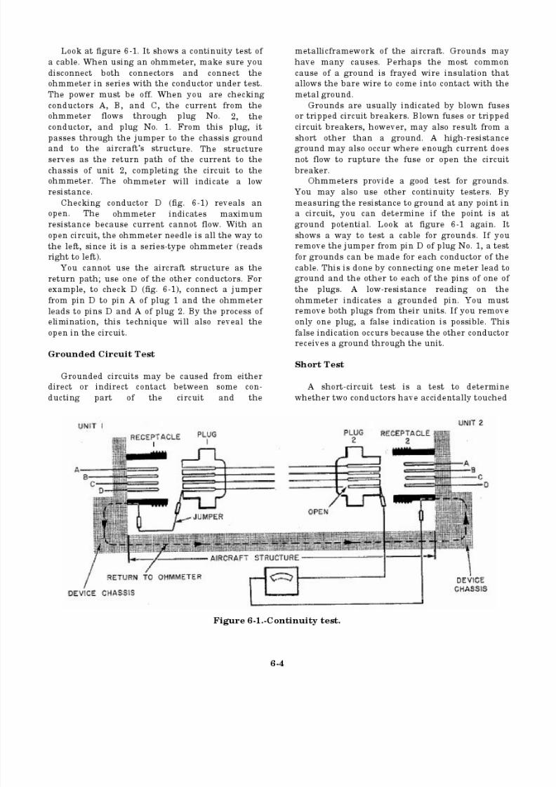
8/14/2019 US Navy Course NAVEDTRA 14028 - Aviation Electronics Technician-Basic
http://slidepdf.com/reader/full/us-navy-course-navedtra-14028-aviation-electronics-technician-basic 211/415
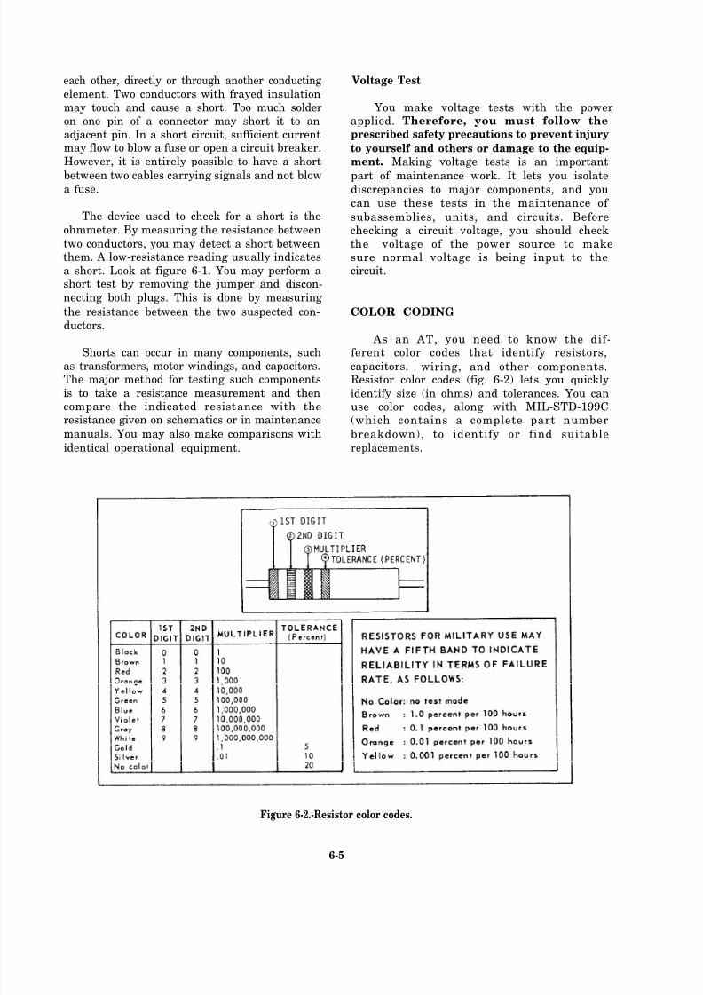
8/14/2019 US Navy Course NAVEDTRA 14028 - Aviation Electronics Technician-Basic
http://slidepdf.com/reader/full/us-navy-course-navedtra-14028-aviation-electronics-technician-basic 212/415

8/14/2019 US Navy Course NAVEDTRA 14028 - Aviation Electronics Technician-Basic
http://slidepdf.com/reader/full/us-navy-course-navedtra-14028-aviation-electronics-technician-basic 213/415
Capacitor color coding is one of two methods number is stamped on the capacitor. For more
used to identify capacitors. Figures 6-3, 6-4, 6-5, information on capacitor identification, you
and 6-6 are several examples of capacitor color should refer to NEETS, module 19, NAVEDTRA
coding for different styles of capacitor. The other 14191, and specific military standards and speci-
method is the typographical method where a fications.
Figure 6-3.-Six-dot color code for mica and molded paper capacitors.
6-6
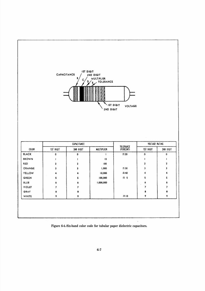
8/14/2019 US Navy Course NAVEDTRA 14028 - Aviation Electronics Technician-Basic
http://slidepdf.com/reader/full/us-navy-course-navedtra-14028-aviation-electronics-technician-basic 214/415
Figure 6-4.-Six-band color code for tubular paper dielectric capacitors.
6-7
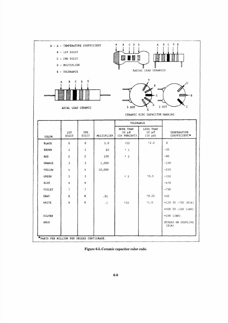
8/14/2019 US Navy Course NAVEDTRA 14028 - Aviation Electronics Technician-Basic
http://slidepdf.com/reader/full/us-navy-course-navedtra-14028-aviation-electronics-technician-basic 215/415
Figure 6-5.-Ceramic capacitor color code.
6-8

8/14/2019 US Navy Course NAVEDTRA 14028 - Aviation Electronics Technician-Basic
http://slidepdf.com/reader/full/us-navy-course-navedtra-14028-aviation-electronics-technician-basic 216/415
Figure 6-6.-Mica capacitor color code.
6-9
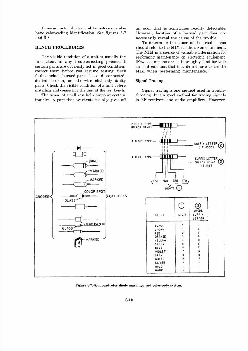
8/14/2019 US Navy Course NAVEDTRA 14028 - Aviation Electronics Technician-Basic
http://slidepdf.com/reader/full/us-navy-course-navedtra-14028-aviation-electronics-technician-basic 217/415
Semiconductor diodes and transformers alsohave color-coding identification. See figures 6-7
and 6-8.
BENCH PROCEDURES
The visible condition of a unit is usually the
first check in any troubleshooting process. If certain parts are obviously not in good condition,correct them before you resume testing. Such
faults include burned parts, loose, disconnected,
dented, broken, or otherwise obviously faulty
parts. Check the visible condition of a unit before
installing and connecting the unit at the test bench.The sense of smell can help pinpoint certain
troubles. A part that overheats usually gives off
an odor that is sometimes readily detectable.However, location of a burned part does not
necessarily reveal the cause of the trouble.To determine the cause of the trouble, you
should refer to the MIM for the given equipment.
The MIM is a source of valuable information for
performing maintenance on electronic equipment.
(Few technicians are so thoroughly familiar withan electronic unit that they do not have to use theMIM when performing maintenance.)
Signal Tracing
Signal tracing is one method used in trouble-shooting. It is a good method for tracing signalsin RF receivers and audio amplifiers. However,
Figure 6-7.-Semiconductor diode markings and color-code system.
6-10
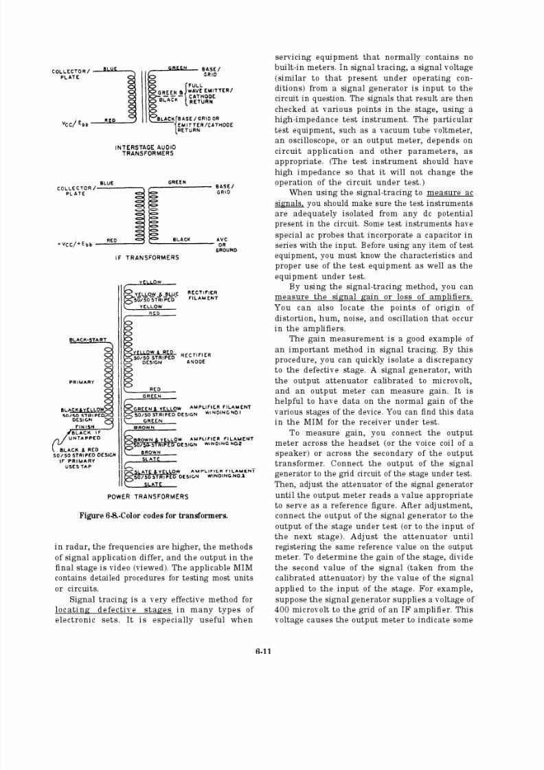
8/14/2019 US Navy Course NAVEDTRA 14028 - Aviation Electronics Technician-Basic
http://slidepdf.com/reader/full/us-navy-course-navedtra-14028-aviation-electronics-technician-basic 218/415

8/14/2019 US Navy Course NAVEDTRA 14028 - Aviation Electronics Technician-Basic
http://slidepdf.com/reader/full/us-navy-course-navedtra-14028-aviation-electronics-technician-basic 219/415
8/14/2019 US Navy Course NAVEDTRA 14028 - Aviation Electronics Technician-Basic
http://slidepdf.com/reader/full/us-navy-course-navedtra-14028-aviation-electronics-technician-basic 220/415
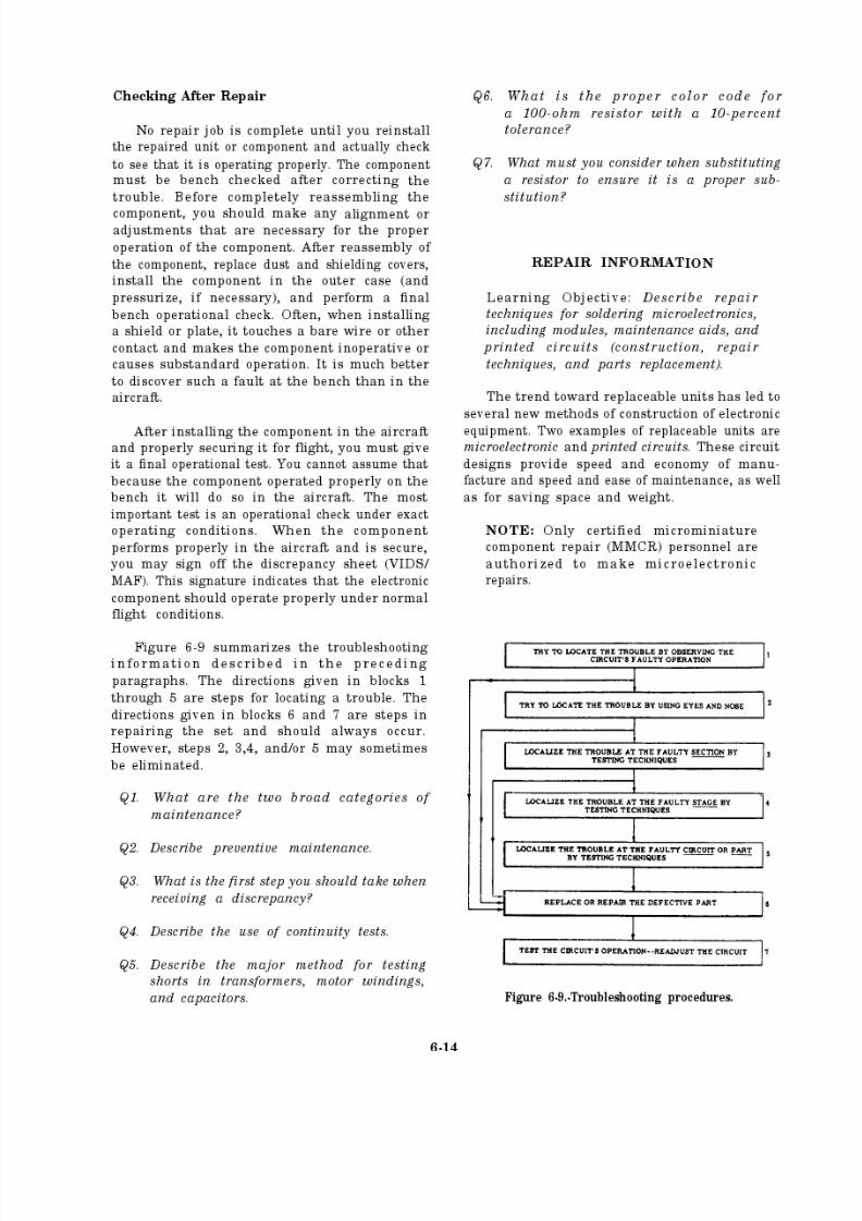
8/14/2019 US Navy Course NAVEDTRA 14028 - Aviation Electronics Technician-Basic
http://slidepdf.com/reader/full/us-navy-course-navedtra-14028-aviation-electronics-technician-basic 221/415
8/14/2019 US Navy Course NAVEDTRA 14028 - Aviation Electronics Technician-Basic
http://slidepdf.com/reader/full/us-navy-course-navedtra-14028-aviation-electronics-technician-basic 222/415

8/14/2019 US Navy Course NAVEDTRA 14028 - Aviation Electronics Technician-Basic
http://slidepdf.com/reader/full/us-navy-course-navedtra-14028-aviation-electronics-technician-basic 223/415
you are inspecting and servicing equipment andcomponents in confined spaces.
A magnifying device is essential for inspecting
minute parts. If the magnifier is on a stand, youwill have both hands free for other tasks.
When you work on a removed printed circuit
or terminal board, the item must remain still. Youcan use a module holder or module jig for thispurpose. The jig provides support and preventsflexing or slipping. Securing the jig to theworktable leaves both of your hands free to work
on the board.
For any resoldering operation, mount the part
so the terminals point out and down. Place thesoldering iron under the terminals so the solderflows away from the joint. To resolder the joint,invert the part.
Some technicians use a drawer or box with a
white cloth to catch (trap) any small parts droppedduring maintenance. (See fig. 6-10.)
NOTE: This procedure is no longer
recommended since the cloth and/or boxmay contain an electrostatic charge. The
static charge may damage solid-statecomponents when they fall on the cloth.Ensure you and your fellow workers DO
NOT use this unless approved by proper
Figure 6-10.-Trap for catching small dropped parts.
For further information on procedures to
follow when resoldering components, refer to Assembly Electronics Repair, Standard Mainte-
nance Practices, NAVAIR 01-1A-23.
PRINTED CIRCUITS
The trend toward replaceable units has led to
several new methods of construction of electronicequipment. An example of such a unit is theprinted circuit. This type of circuit provides forspeed and economy of manufacture and speed and
ease of maintenance, as well as for saving space
authority. and weight.
ANSWERS FOR REVIEW QUESTIONS Q1. THROUGH Q7.
A1. Preventive and corrective maintenance.
A2. Preventive maintenance is maintenance performed to reduce the
likelihood of future troubles or malfunctions.
A3. Determine if the equipment in question is actually faulty.
A4. To check for opens or to see if a circuit is complete or continuous.
A5. The major method for testing these components is to take
resistance m easurements and compare them with schematics, MIMs, or identical operational equipment.
A6. 1st Digit: Brown; 2nd digit: Black; Multiplier: Brown; Tolerance:
Silver; see figure 6-2.
A7. You must consider ohmic value, wattage rating, tolerance, physical dimensions, and type of construction.
6-16
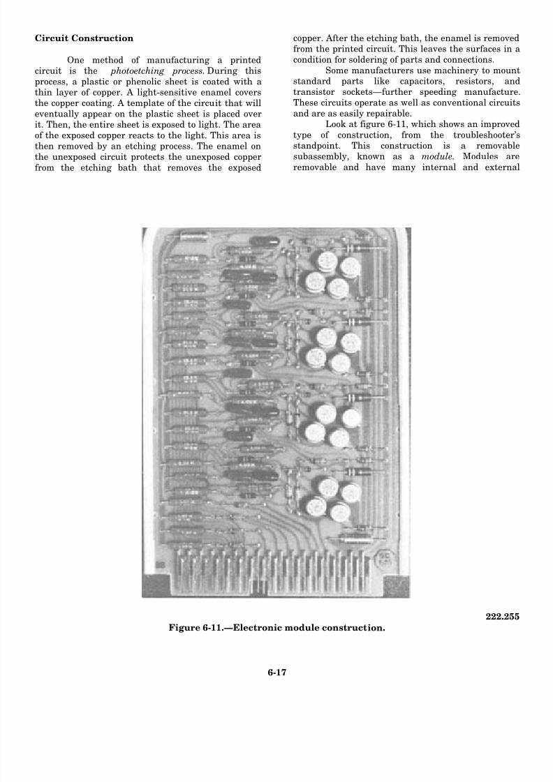
8/14/2019 US Navy Course NAVEDTRA 14028 - Aviation Electronics Technician-Basic
http://slidepdf.com/reader/full/us-navy-course-navedtra-14028-aviation-electronics-technician-basic 224/415
Circuit Construction
One method of manufacturing a printedcircuit is the photoetching process. During this
process, a plastic or phenolic sheet is coated with athin layer of copper. A light-sensitive enamel coversthe copper coating. A template of the circuit that willeventually appear on the plastic sheet is placed overit. Then, the entire sheet is exposed to light. The area
of the exposed copper reacts to the light. This area isthen removed by an etching process. The enamel onthe unexposed circuit protects the unexposed copper
from the etching bath that removes the exposed
copper. After the etching bath, the enamel is removedfrom the printed circuit. This leaves the surfaces in acondition for soldering of parts and connections.
Some manufacturers use machinery to mountstandard parts like capacitors, resistors, andtransistor sockets—further speeding manufacture
These circuits operate as well as conventional circuitsand are as easily repairable.
Look at figure 6-11, which shows an improved
type of construction, from the troubleshooter’sstandpoint. This construction is a removablesubassembly, known as a module. Modules are
removable and have many internal and external
222.255
Figure 6-11.—Electronic module construction.
6-17
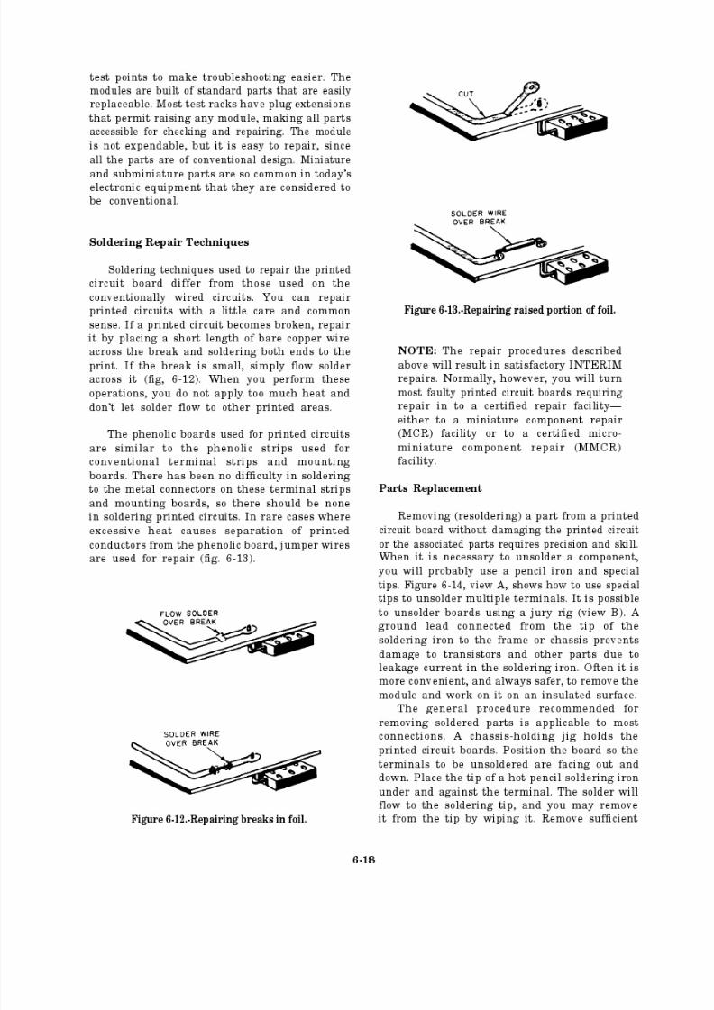
8/14/2019 US Navy Course NAVEDTRA 14028 - Aviation Electronics Technician-Basic
http://slidepdf.com/reader/full/us-navy-course-navedtra-14028-aviation-electronics-technician-basic 225/415
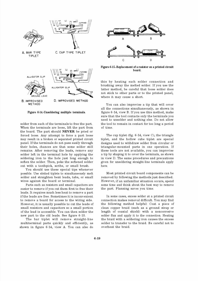
8/14/2019 US Navy Course NAVEDTRA 14028 - Aviation Electronics Technician-Basic
http://slidepdf.com/reader/full/us-navy-course-navedtra-14028-aviation-electronics-technician-basic 226/415

8/14/2019 US Navy Course NAVEDTRA 14028 - Aviation Electronics Technician-Basic
http://slidepdf.com/reader/full/us-navy-course-navedtra-14028-aviation-electronics-technician-basic 227/415
The proper methods of solder removal andapplication are shown in figure 6-16, views A, B,
and C. View A shows the correct and incorrectmethods of solder application. The correct
method for removing solder from a componentwithout damaging the printed wiring circuits is
Figure 6-16.-Soldering techniques.
shown in view B, View C shows the correctmethod of applying solder to a replaced
component.
Resistors
One of the most important considerations
when replacing a resistor is the wattage value of the resistor. The wattage rating is a measure of the ability of the resistor to dissipate heat. Thewattage value is a function of the dimensions of
the resistor.The selection of a resistor with a safe wattage
value is based on a consideration of the working
conditions of the resistor in the circuit. Consider,for example, the replacement of an 850-ohm
resistor with one of equal ohmic value but with
a tolerance of ±20 percent. Suppose the normal voltage existing across the resistor is 40 volts.Because of the 20-percent tolerance, the actual
resistance of the replacement may be as much as1,020 ohms or as little as 680 ohms. If the resistorwith the lesser value is chosen (the more
unfavorable from a heat-dissipating standpoint),
the power that may be developed in the resistorunder circuit conditions is found as follows:
To allow a sufficient safety margin, a resistorshould be capable of dissipating from 1.5 to 2
times the power it will actually meet. In the above
example, this value is not more than 4.7 watts.
Since a 5-watt resistor is the next standard size
above the 4.7-watt value, this is a desirablewattage rating for the replacement.
Under emergency conditions, you may need
to combine resistors in series or in parallel to geta desired resistance value. When doing this, youshould avoid a voltage distribution (or currentdistribution) that would cause any low-wattageresistor in the combination to dissipate an
excessive amount of heat. Suppose, for example,
that you combine two 10-watt resistors of 1-ohm value with a 2-watt resistor of 10-ohm value in
a series circuit with 12 volts applied. The totalwattage now being dissipated by the 10-ohm,
2-watt resistor would be 10 watts, a value far morethan its capabilities. Therefore, you must consider
6-20
2
8/14/2019 US Navy Course NAVEDTRA 14028 - Aviation Electronics Technician-Basic
http://slidepdf.com/reader/full/us-navy-course-navedtra-14028-aviation-electronics-technician-basic 228/415

8/14/2019 US Navy Course NAVEDTRA 14028 - Aviation Electronics Technician-Basic
http://slidepdf.com/reader/full/us-navy-course-navedtra-14028-aviation-electronics-technician-basic 229/415
pins. Now, repeat the cleaning, and then separatethe wires evenly.
2. Thoroughly mix the accelerator and base
compound (fig. 6-17). The ratio of accelerator to
base compound is critical; therefore, you mustadd the entire quantity of accelerator furnished
to the base compound.
3. Place the plugs or receptacles on a table,arranging them so gravity will draw the sealer to
the bottom of the plug. Box receptacles of plugswithout back shells require fittings with a mold
made of masking tape, cellophane tape, or its
equivalent (fig. 6-18, view A). This will retain the
Figure 6-17.-Combining accelerator with base compound.
Figure 6-18.-(A) Making a mold from masking tape;(B) finished potted plug.
sealant during the curing process. If using the back
shell, apply a slight amount of oil to the inner
surface to prevent the compound from adheringto it.
4. Use a spatula, putty knife, or paddle toapply the compound. Ensure good packing
around the base of the pins. When potting,completely fill the part, or at least fill it to a pointwhere you can cover about three-eighths inch of insulated wire. Now, allow the compound to cure.
ANSWERS FOR REVIEW QUESTIONS Q8. THROUGH Q10.
A8.
A9.
A10.
Only c ertified microminiature component repair (MMCR) personnel.
Component damage during maintenance usually results from excess heat during repair, reversed polarity of ohmmeters while
checkin g for continuity , excessive voltage application or signalstrength during testing, rough handling, or using the wrong tools
or materials.
Assembly Electronics Repair, Standard Maintenance Practices, NAVAIR 01-1A-23.
6-22
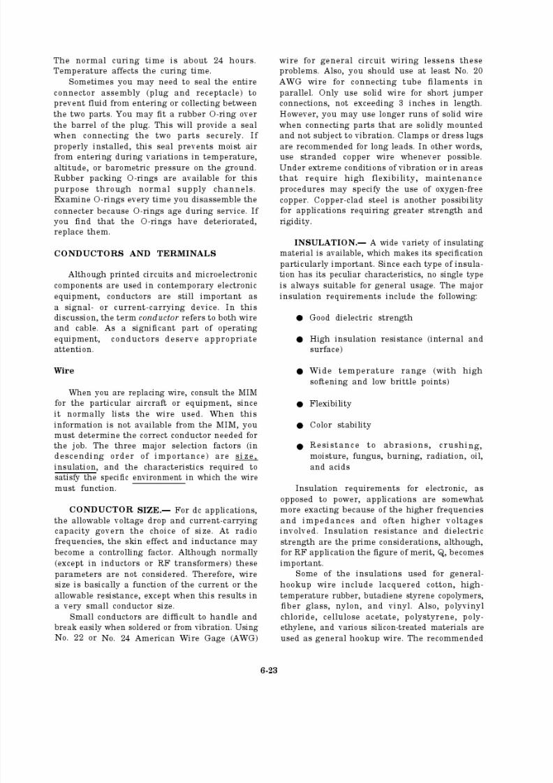
8/14/2019 US Navy Course NAVEDTRA 14028 - Aviation Electronics Technician-Basic
http://slidepdf.com/reader/full/us-navy-course-navedtra-14028-aviation-electronics-technician-basic 230/415
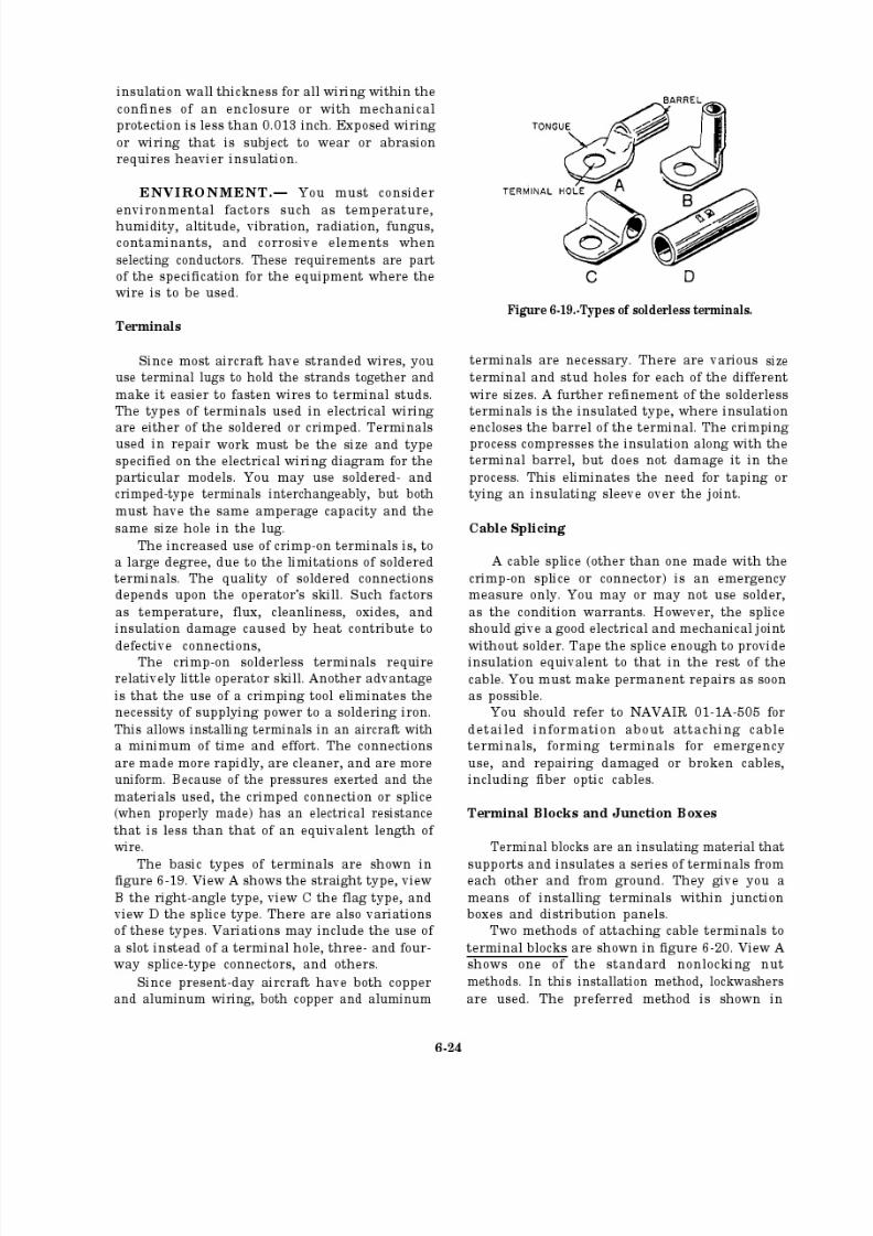
8/14/2019 US Navy Course NAVEDTRA 14028 - Aviation Electronics Technician-Basic
http://slidepdf.com/reader/full/us-navy-course-navedtra-14028-aviation-electronics-technician-basic 231/415
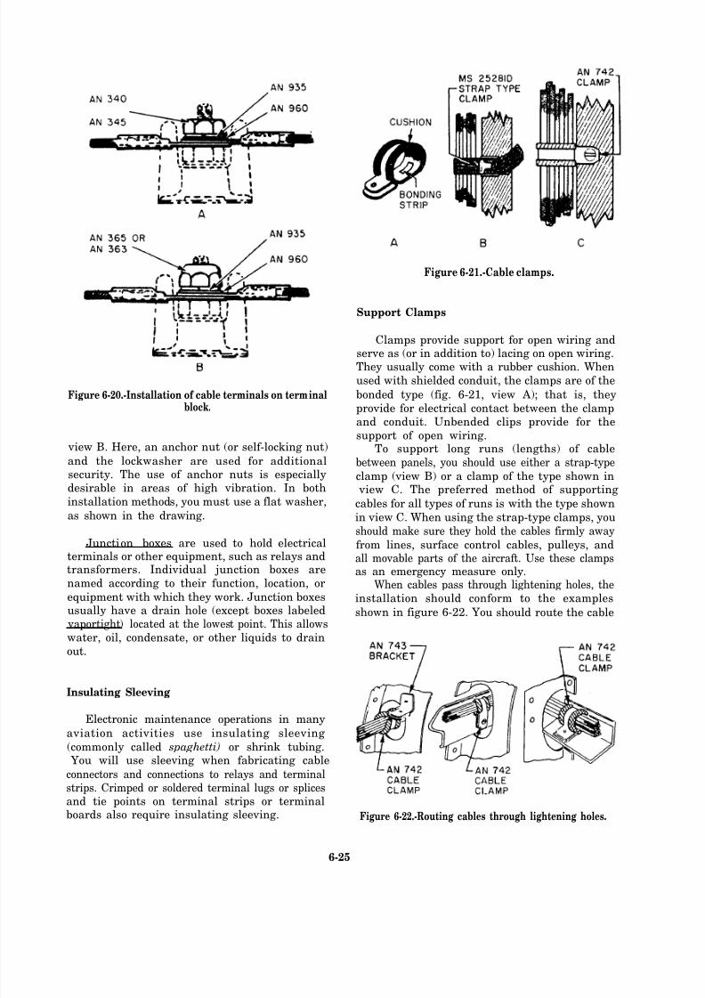
8/14/2019 US Navy Course NAVEDTRA 14028 - Aviation Electronics Technician-Basic
http://slidepdf.com/reader/full/us-navy-course-navedtra-14028-aviation-electronics-technician-basic 232/415
Figure 6-21.-Cable clamps.
Figure 6-20.-Installation of cable terminals on terminalblock.
view B. Here, an anchor nut (or self-locking nut)
and the lockwasher are used for additionalsecurity. The use of anchor nuts is especiallydesirable in areas of high vibration. In both
installation methods, you must use a flat washer,
as shown in the drawing.
Junction boxes are used to hold electricalterminals or other equipment, such as relays andtransformers. Individual junction boxes are
named according to their function, location, or
equipment with which they work. Junction boxesusually have a drain hole (except boxes labeled
vaportight) located at the lowest point. This allows
water, oil, condensate, or other liquids to drain
out.
Insulating Sleeving
Electronic maintenance operations in many
aviation activities use insulating sleeving
(commonly called spaghetti) or shrink tubing. You will use sleeving when fabricating cable
connectors and connections to relays and terminalstrips. Crimped or soldered terminal lugs or splicesand tie points on terminal strips or terminalboards also require insulating sleeving.
Support Clamps
Clamps provide support for open wiring and
serve as (or in addition to) lacing on open wiring.They usually come with a rubber cushion. When
used with shielded conduit, the clamps are of the
bonded type (fig. 6-21, view A); that is, they
provide for electrical contact between the clampand conduit. Unbended clips provide for the
support of open wiring.To support long runs (lengths) of cable
between panels, you should use either a strap-type
clamp (view B) or a clamp of the type shown in view C. The preferred method of supporting
cables for all types of runs is with the type shown
in view C. When using the strap-type clamps, you
should make sure they hold the cables firmly away
from lines, surface control cables, pulleys, andall movable parts of the aircraft. Use these clampsas an emergency measure only.
When cables pass through lightening holes, the
installation should conform to the examples
shown in figure 6-22. You should route the cable
Figure 6-22.-Routing cables through lightening holes.
6-25
8/14/2019 US Navy Course NAVEDTRA 14028 - Aviation Electronics Technician-Basic
http://slidepdf.com/reader/full/us-navy-course-navedtra-14028-aviation-electronics-technician-basic 233/415
clear of the edges of the lightening hole to avoid
any chance of chafing the insulation.
Replacing Wiring
When you install or replace wire or wire
bundles, make sure there is no excessive slack
between cable clamps. Normally, there should beno more than a one-half inch deflection with
normal hand pressure. However, you should allow
sufficient slack at each end of the wire or wirebundles for the following reasons:
To allow easy removal and connection of plugs
To allow replacement of terminals twotimes
To prevent mechanical strain on the wires
To permit free movement of shock- and vibration-mounted equipment
To allow movement of equipment formaintenance
Normally, bends in individual wires should
have a minimum bend radius of 10 times thediameter of the bundles. However, where the wirehas suitable support at each end of the bend, aminimum bend radius of three times the diameter
of the bundle is acceptable.
Never bend coaxial cable to a radius smallerthan six times its outside diameter. Damage willresult. Route coaxial cables as directly as possible,
avoiding any unnecessary bends.
Wires passing through a bulkhead require
support at each hole by a cable clamp. If theclearance between the wires and the edge of thehole is less than one-fourth inch, you should use
a suitable grommet in the hole. See figure 6-23.
You must maintain a minimum clearance of
3 inches between wiring and control cables. If thiscannot be done, install guards to prevent thewiring from contacting the control cables. When
the wiring must be parallel to plumbing carryingflammable fluids or oxygen, maintain as muchseparation as possible. Support the wiring so itcannot come closer than one-half inch to theplumbing. Never support any wire or wire bundle
from a plumbing line that carries combustible
liquids or oxygen.
Install cable clamps so the mounting screws
are above the wire bundle (fig. 6-24). Otherwise,
Figure 6-23.-Cable clamp and grommet at bulkhead hole.
the weight of the cable may bend and break the
clamp. It is also desirable that the back of the
clamp rest against a structural member, if
practical. Be careful not to pinch wires in the cableclamp.
TYING AND LACING WIRE GROUPS AND BUNDLES.— A wire group is two or morewires tied or laced together to give identity to an
individual system. A wire bundle is two or morewires or groups tied or laced together to provide
Figure 6-24.-Safe angles for cable clamps.
6-26
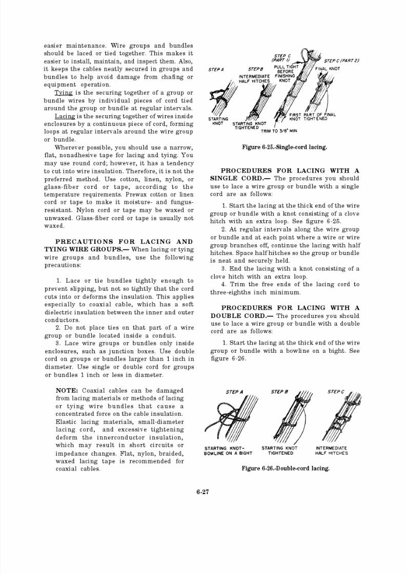
8/14/2019 US Navy Course NAVEDTRA 14028 - Aviation Electronics Technician-Basic
http://slidepdf.com/reader/full/us-navy-course-navedtra-14028-aviation-electronics-technician-basic 234/415
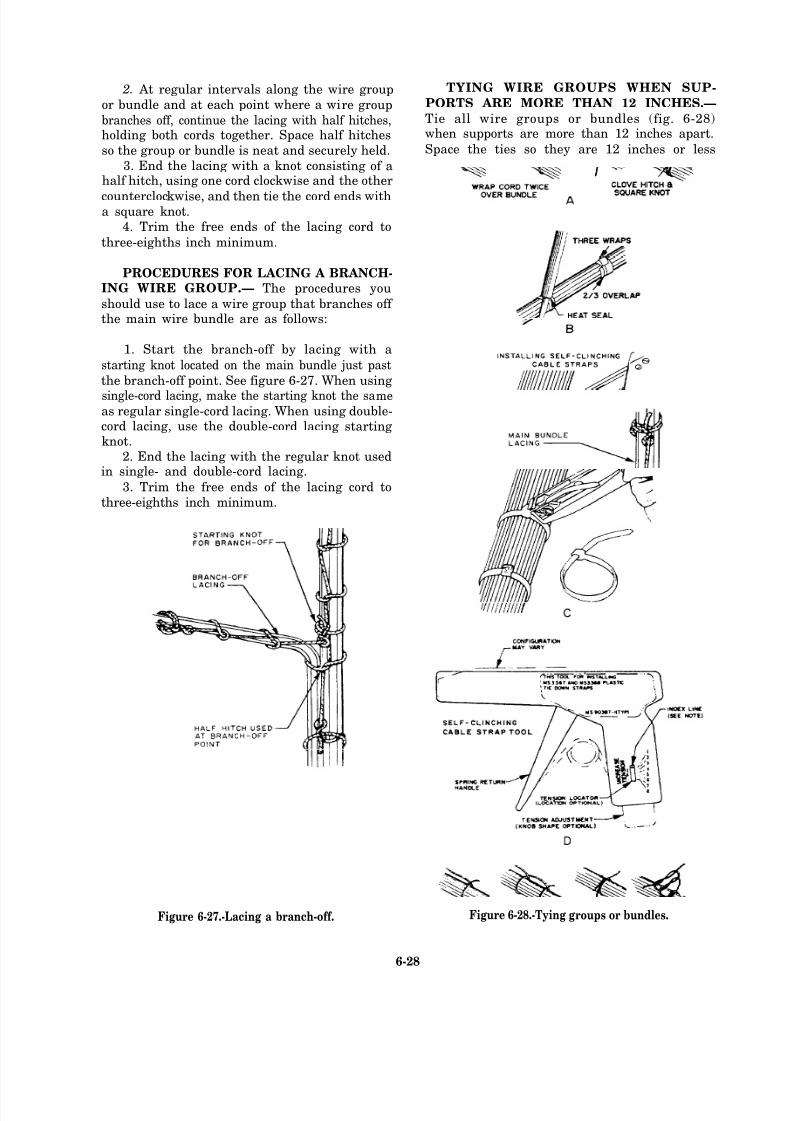
8/14/2019 US Navy Course NAVEDTRA 14028 - Aviation Electronics Technician-Basic
http://slidepdf.com/reader/full/us-navy-course-navedtra-14028-aviation-electronics-technician-basic 235/415
2. At regular intervals along the wire group
or bundle and at each point where a wire group
branches off, continue the lacing with half hitches,holding both cords together. Space half hitches
so the group or bundle is neat and securely held.
3. End the lacing with a knot consisting of ahalf hitch, using one cord clockwise and the other
counterclockwise, and then tie the cord ends witha square knot.
4. Trim the free ends of the lacing cord to
three-eighths inch minimum.
PROCEDURES FOR LACING A BRANCH-ING WIRE GROUP.— The procedures you
should use to lace a wire group that branches off the main wire bundle are as follows:
1. Start the branch-off by lacing with a
starting knot located on the main bundle just past
the branch-off point. See figure 6-27. When using
single-cord lacing, make the starting knot the sameas regular single-cord lacing. When using double-cord lacing, use the double-cord lacing startingknot.
2. End the lacing with the regular knot usedin single- and double-cord lacing.
3. Trim the free ends of the lacing cord to
three-eighths inch minimum.
Figure 6-27.-Lacing a branch-off.
TYING WIRE GROUPS WHEN SUP-
PORTS ARE MORE THAN 12 INCHES.—
Tie all wire groups or bundles (fig. 6-28)when supports are more than 12 inches apart.
Space the ties so they are 12 inches or less
Figure 6-28.-Tying groups or bundles.
6-28
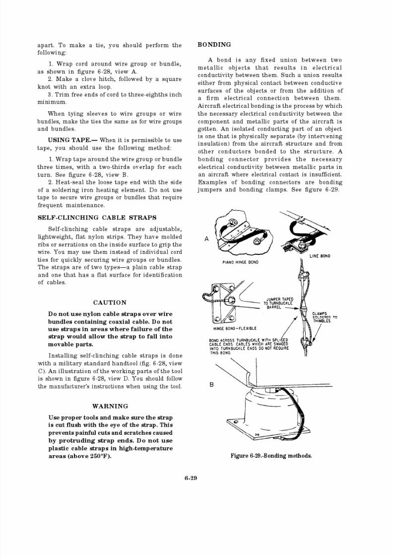
8/14/2019 US Navy Course NAVEDTRA 14028 - Aviation Electronics Technician-Basic
http://slidepdf.com/reader/full/us-navy-course-navedtra-14028-aviation-electronics-technician-basic 236/415

8/14/2019 US Navy Course NAVEDTRA 14028 - Aviation Electronics Technician-Basic
http://slidepdf.com/reader/full/us-navy-course-navedtra-14028-aviation-electronics-technician-basic 237/415
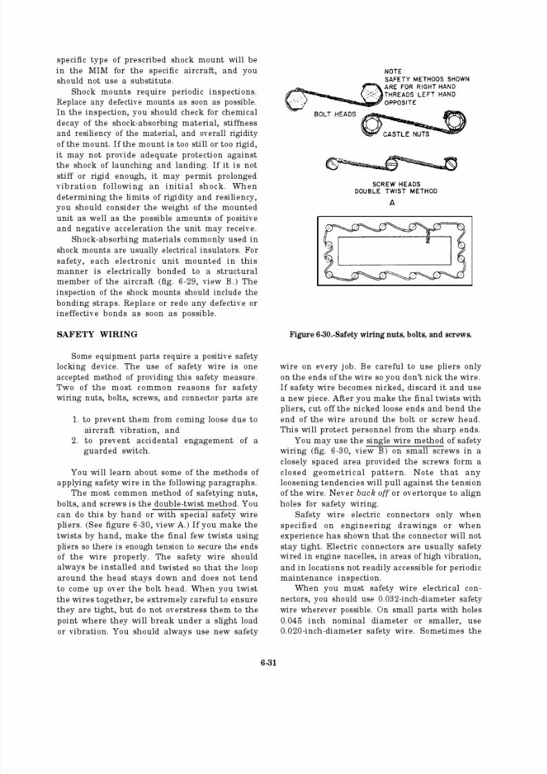
8/14/2019 US Navy Course NAVEDTRA 14028 - Aviation Electronics Technician-Basic
http://slidepdf.com/reader/full/us-navy-course-navedtra-14028-aviation-electronics-technician-basic 238/415
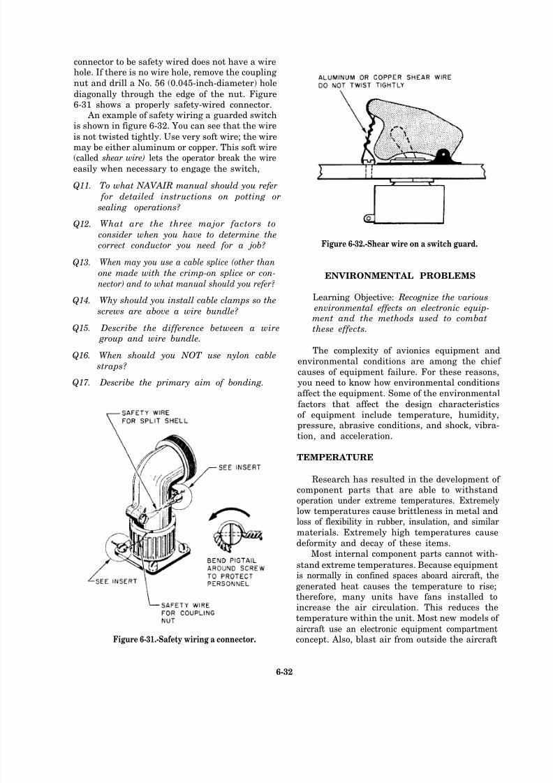
8/14/2019 US Navy Course NAVEDTRA 14028 - Aviation Electronics Technician-Basic
http://slidepdf.com/reader/full/us-navy-course-navedtra-14028-aviation-electronics-technician-basic 239/415
connector to be safety wired does not have a wirehole. If there is no wire hole, remove the coupling
nut and drill a No. 56 (0.045-inch-diameter) hole
diagonally through the edge of the nut. Figure6-31 shows a properly safety-wired connector.
An example of safety wiring a guarded switchis shown in figure 6-32. You can see that the wire
is not twisted tightly. Use very soft wire; the wiremay be either aluminum or copper. This soft wire(called shear wire) lets the operator break the wire
easily when necessary to engage the switch,
Q11.
Q12.
Q13.
Q14.
Q15.
Q16.
Q17.
To what NAVAIR manual should you refer
for detailed instructions on potting or
sealing operations?
What are the three major factors to
consider when you have to determine the
correct conductor you need for a job?
When may you use a cable splice (other than
one made with the crimp-on splice or con-nector) and to what manual should you refer?
Why should you install cable clamps so the
screws are above a wire bundle?
Describe the difference between a wire group and wire bundle.
When should you NOT use nylon cable
straps?
Describe the primary aim of bonding.
Figure 6-31.-Safety wiring a connector.
Figure 6-32.-Shear wire on a switch guard.
ENVIRONMENTAL PROBLEMS
Learning Objective: Recognize the various
environmental effects on electronic equip-ment and the methods used to combat
these effects.
The complexity of avionics equipment and
environmental conditions are among the chief
causes of equipment failure. For these reasons,you need to know how environmental conditions
affect the equipment. Some of the environmental
factors that affect the design characteristics
of equipment include temperature, humidity,pressure, abrasive conditions, and shock, vibra-
tion, and acceleration.
TEMPERATURE
Research has resulted in the development of component parts that are able to withstandoperation under extreme temperatures. Extremelylow temperatures cause brittleness in metal andloss of flexibility in rubber, insulation, and similar
materials. Extremely high temperatures cause
deformity and decay of these items.Most internal component parts cannot with-
stand extreme temperatures. Because equipmentis normally in confined spaces aboard aircraft, the
generated heat causes the temperature to rise;therefore, many units have fans installed toincrease the air circulation. This reduces the
temperature within the unit. Most new models of
aircraft use an electronic equipment compartmentconcept. Also, blast air from outside the aircraft
6-32
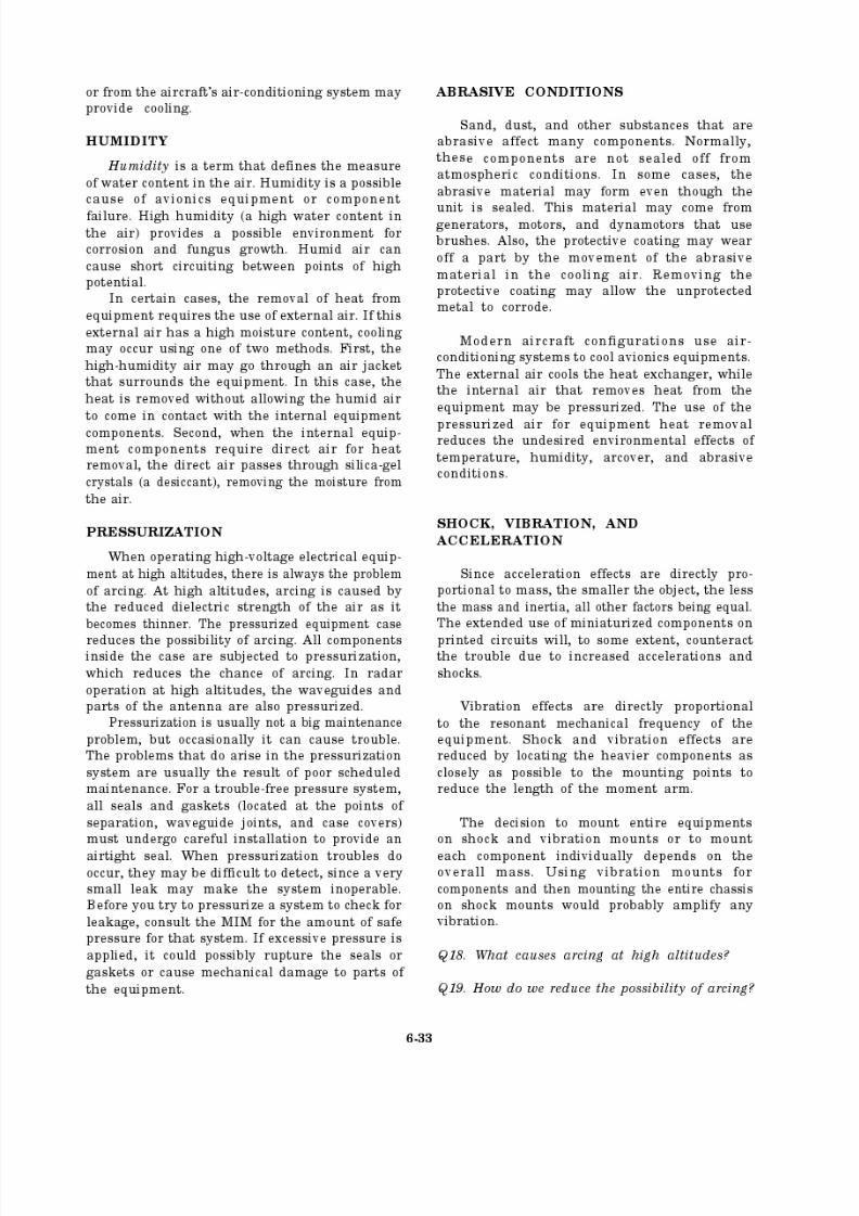
8/14/2019 US Navy Course NAVEDTRA 14028 - Aviation Electronics Technician-Basic
http://slidepdf.com/reader/full/us-navy-course-navedtra-14028-aviation-electronics-technician-basic 240/415
8/14/2019 US Navy Course NAVEDTRA 14028 - Aviation Electronics Technician-Basic
http://slidepdf.com/reader/full/us-navy-course-navedtra-14028-aviation-electronics-technician-basic 241/415
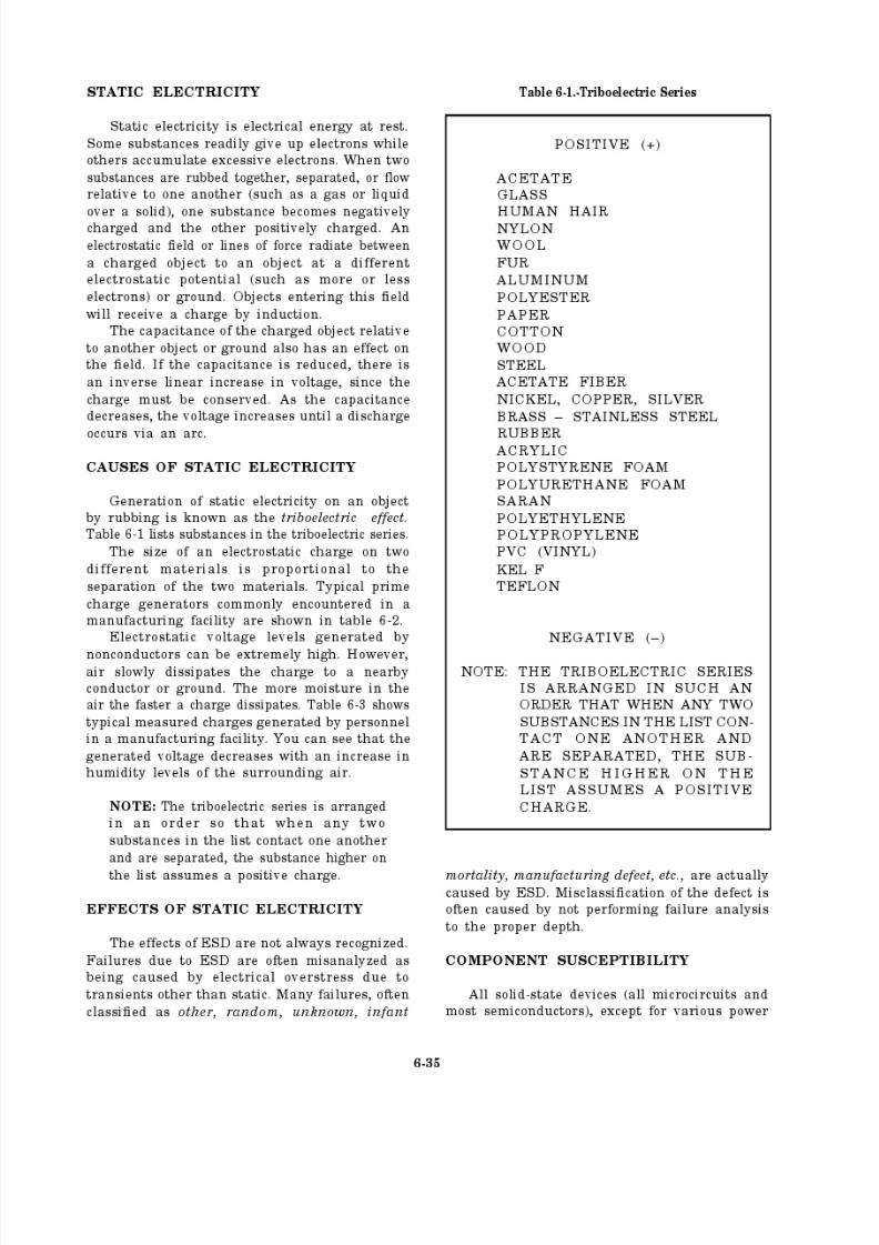
8/14/2019 US Navy Course NAVEDTRA 14028 - Aviation Electronics Technician-Basic
http://slidepdf.com/reader/full/us-navy-course-navedtra-14028-aviation-electronics-technician-basic 242/415
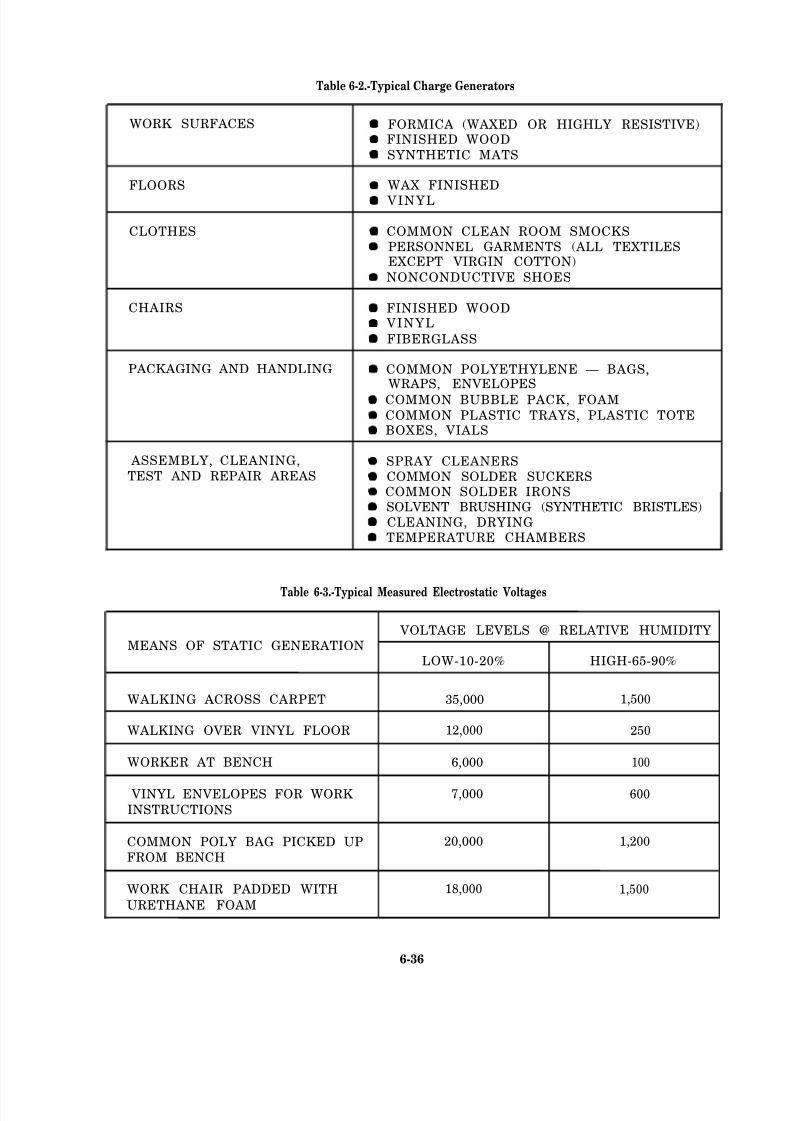
8/14/2019 US Navy Course NAVEDTRA 14028 - Aviation Electronics Technician-Basic
http://slidepdf.com/reader/full/us-navy-course-navedtra-14028-aviation-electronics-technician-basic 243/415
8/14/2019 US Navy Course NAVEDTRA 14028 - Aviation Electronics Technician-Basic
http://slidepdf.com/reader/full/us-navy-course-navedtra-14028-aviation-electronics-technician-basic 244/415
8/14/2019 US Navy Course NAVEDTRA 14028 - Aviation Electronics Technician-Basic
http://slidepdf.com/reader/full/us-navy-course-navedtra-14028-aviation-electronics-technician-basic 245/415
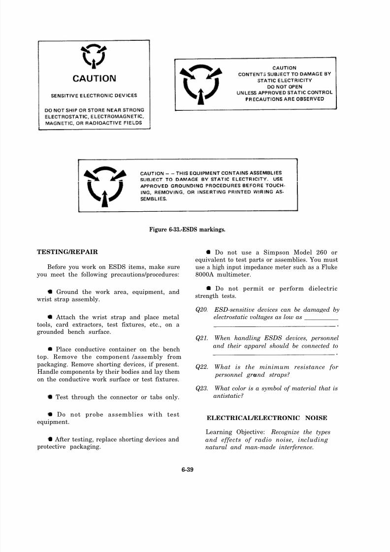
8/14/2019 US Navy Course NAVEDTRA 14028 - Aviation Electronics Technician-Basic
http://slidepdf.com/reader/full/us-navy-course-navedtra-14028-aviation-electronics-technician-basic 246/415
Figure 6-33.-ESDS markings.
TESTING/REPAIR
Before you work on ESDS items, make sure
you meet the following precautions/procedures:
Ground the work area, equipment, andwrist strap assembly.
Attach the wrist strap and place metaltools, card extractors, test fixtures, etc., on agrounded bench surface.
Place conductive container on the bench
top. Remove the component /assembly from
packaging. Remove shorting devices, if present.Handle components by their bodies and lay them
on the conductive work surface or test fixtures.
Test through the connector or tabs only.
Do not probe assemblies with testequipment.
After testing, replace shorting devices andprotective packaging.
Do not use a Simpson Model 260 orequivalent to test parts or assemblies. You mustuse a high input impedance meter such as a Fluke8000A multimeter.
Do not permit or perform dielectricstrength tests.
Q20.
Q21.
Q22.
Q23.
ESD-sensitive devices can be damaged by electrostatic voltages as low as ___________
When handling ESDS devices, personnel
and their apparel should be connected to
What is the minimum resistance for
personnel ground straps?
W hat color is a symbol of material that isantistatic?
ELECTRICAL/ELECTRONIC NOISE
Learning Objective: Recognize the types
and effects of radio noise, includingnatural and man-made interference.
6-39
8/14/2019 US Navy Course NAVEDTRA 14028 - Aviation Electronics Technician-Basic
http://slidepdf.com/reader/full/us-navy-course-navedtra-14028-aviation-electronics-technician-basic 247/415

8/14/2019 US Navy Course NAVEDTRA 14028 - Aviation Electronics Technician-Basic
http://slidepdf.com/reader/full/us-navy-course-navedtra-14028-aviation-electronics-technician-basic 248/415
8/14/2019 US Navy Course NAVEDTRA 14028 - Aviation Electronics Technician-Basic
http://slidepdf.com/reader/full/us-navy-course-navedtra-14028-aviation-electronics-technician-basic 249/415
8/14/2019 US Navy Course NAVEDTRA 14028 - Aviation Electronics Technician-Basic
http://slidepdf.com/reader/full/us-navy-course-navedtra-14028-aviation-electronics-technician-basic 250/415
8/14/2019 US Navy Course NAVEDTRA 14028 - Aviation Electronics Technician-Basic
http://slidepdf.com/reader/full/us-navy-course-navedtra-14028-aviation-electronics-technician-basic 251/415
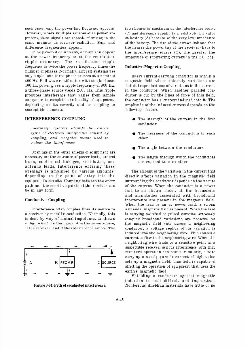
8/14/2019 US Navy Course NAVEDTRA 14028 - Aviation Electronics Technician-Basic
http://slidepdf.com/reader/full/us-navy-course-navedtra-14028-aviation-electronics-technician-basic 252/415
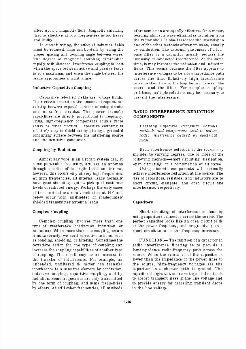
8/14/2019 US Navy Course NAVEDTRA 14028 - Aviation Electronics Technician-Basic
http://slidepdf.com/reader/full/us-navy-course-navedtra-14028-aviation-electronics-technician-basic 253/415
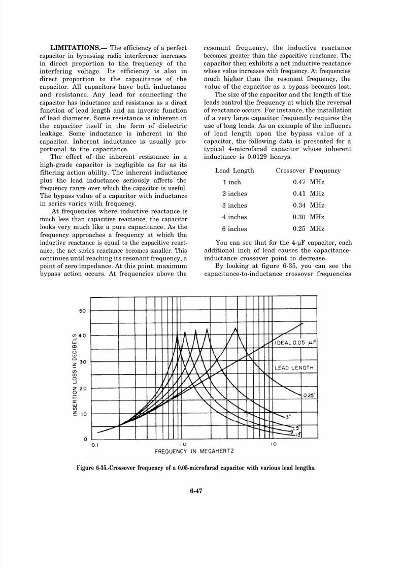
8/14/2019 US Navy Course NAVEDTRA 14028 - Aviation Electronics Technician-Basic
http://slidepdf.com/reader/full/us-navy-course-navedtra-14028-aviation-electronics-technician-basic 254/415
LIMITATIONS.— The efficiency of a perfect
capacitor in bypassing radio interference increases
in direct proportion to the frequency of theinterfering voltage. Its efficiency is also in
direct proportion to the capacitance of thecapacitor. All capacitors have both inductance
and resistance. Any lead for connecting the
capacitor has inductance and resistance as a directfunction of lead length and an inverse function
of lead diameter. Some resistance is inherent inthe capacitor itself in the form of dielectricleakage. Some inductance is inherent in the
capacitor. Inherent inductance is usually pro-
portional to the capacitance.The effect of the inherent resistance in a
high-grade capacitor is negligible as far as its
filtering action ability. The inherent inductance
plus the lead inductance seriously affects the
frequency range over which the capacitor is useful.The bypass value of a capacitor with inductancein series varies with frequency.
At frequencies where inductive reactance is
much less than capacitive reactance, the capacitorlooks very much like a pure capacitance. As the
frequency approaches a frequency at which the
inductive reactance is equal to the capacitive react-
ance, the net series reactance becomes smaller. This
continues until reaching its resonant frequency, apoint of zero impedance. At this point, maximumbypass action occurs. At frequencies above the
resonant frequency, the inductive reactance
becomes greater than the capacitive reactance. The
capacitor then exhibits a net inductive reactancewhose value increases with frequency. At frequencies
much higher than the resonant frequency, the
value of the capacitor as a bypass becomes lost.
The size of the capacitor and the length of the
leads control the frequency at which the reversal
of reactance occurs. For instance, the installationof a very large capacitor frequently requires the
use of long leads. As an example of the influence
of lead length upon the bypass value of acapacitor, the following data is presented for atypical 4-microfarad capacitor whose inherent
inductance is 0.0129 henrys.
Lead Length Crossover Frequency
1 inch 0.47 MHz
2 inches 0.41 MHz
3 inches 0.34 MHz
4 inches 0.30 MHz
6 inches 0.25 MHz
You can see that for the 4-µF capacitor, each
additional inch of lead causes the capacitance-
inductance crossover point to decrease.By looking at figure 6-35, you can see the
capacitance-to-inductance crossover frequencies
Figure 6-35.-Crossover frequency of a 0.05-microfarad capacitor with various lead lengths.
6-47

8/14/2019 US Navy Course NAVEDTRA 14028 - Aviation Electronics Technician-Basic
http://slidepdf.com/reader/full/us-navy-course-navedtra-14028-aviation-electronics-technician-basic 255/415
for various lead lengths of a 0.05 µF capacitor.Notice the difference in the crossover frequencies
for the 3-inch lead of the 4-microfarad capacitor
and the 3-inch lead of the 0.05-µF capacitor infigure 6-35.
COAXIAL FEEDTHROUGH CAPACI-
TORS.— Coaxial feedthrough capacitors are
available with capacitances from 0.00005 to about2µF. These capacitors work well up to frequencies
several times those at which capacitors with leads
become useless.The curves shown in figure 6-36 compare the
bypass value of a feedthrough capacitor of 0.05µF with that of a theoretically perfect capacitorof the same capacitance. The feedthrough
capacitor differs from the capacitor with leads.
The feedthrough capacitor forms a part of both
the filtered circuit and the shield used to isolate
the filtered source. Lead length has been reducedto zero. The center conductor of the feedthrough
capacitor must carry all the current of the filtered
source, and it must have an adequate currentrating to prevent dc loss or power frequency
insertion loss. Figure 6-37 shows the internal
constructions of feedthrough and conventional
capacitors. Notice the differences in the two types.
SELECTION OF CAPACITORS.— Theselection of capacitors for filtering circuits in
aircraft depends on characteristics such as physical
size, high temperature and humidity tolerances,and physical ruggedness. The capacitors shouldhave at least twice the voltage rating of the circuit
to be filtered. When installing capacitors useminimum lead length.
APPLICATION OF CAPACITIVE FIL-
TERS.— Bypass every circuit carrying an
unintentionally varying voltage or current capable
of causing radio interference to ground by usingsuitable capacitors. When variations cause
Figure 6-36.-Crossover frequency of a 0.05-microfarad feedthrough capacitor.
6-48
8/14/2019 US Navy Course NAVEDTRA 14028 - Aviation Electronics Technician-Basic
http://slidepdf.com/reader/full/us-navy-course-navedtra-14028-aviation-electronics-technician-basic 256/415
Figure 6-40.-Capacitive filtering of a servomotor.
Figure 6-37.-Internal construction of feedthrough andconventional capacitors.
Figure 6-38.-Capacitive filtering of a reversible dc seriesmotor.
interference at both high and low frequencies,
chose and install a capacitor that provides an
adequate insertion loss at the lowest interfered
frequency. The overall capacitance required at lowfrequency may provide inadequate insertion loss
at high frequencies. Therefore, you may need tobridge the capacitor in the shortest and most direct
manner possible by a second capacitor.Install a capacitive filter as near as possible
to the actual source of interference. Hold leadlength to an absolute minimum for two reasons.
First, the lead to the capacitor carries interference
that must not radiate. Second, the lead hasinductance that tends to lower the maximumfrequency for which the capacitor is an effective
bypass.When possible, a filter capacitor should be
installed to make use of any element of the filtered
circuit that provides a better filtering action.
Figures 6-38, 6-39, and 6-40 show the proper useof filter capacitors.
CAPACITIVE FILTERING IN AN AC
CIRCUIT.— Radio interference from slip ring acmotors and generators is transient noise causedby sliding contacts plus high-frequency energy
from other internal sources. For this reason,
Figure 6-39.-Capacitive filtering of a three-phase attenuator.
6-49
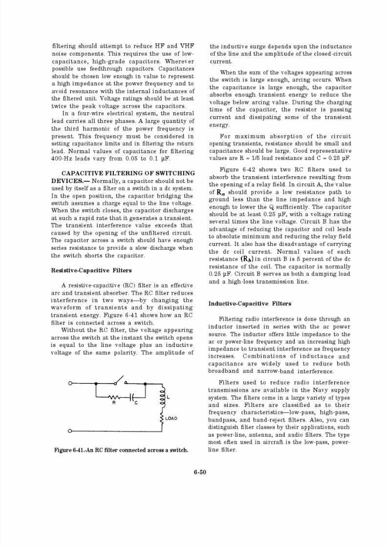
8/14/2019 US Navy Course NAVEDTRA 14028 - Aviation Electronics Technician-Basic
http://slidepdf.com/reader/full/us-navy-course-navedtra-14028-aviation-electronics-technician-basic 257/415
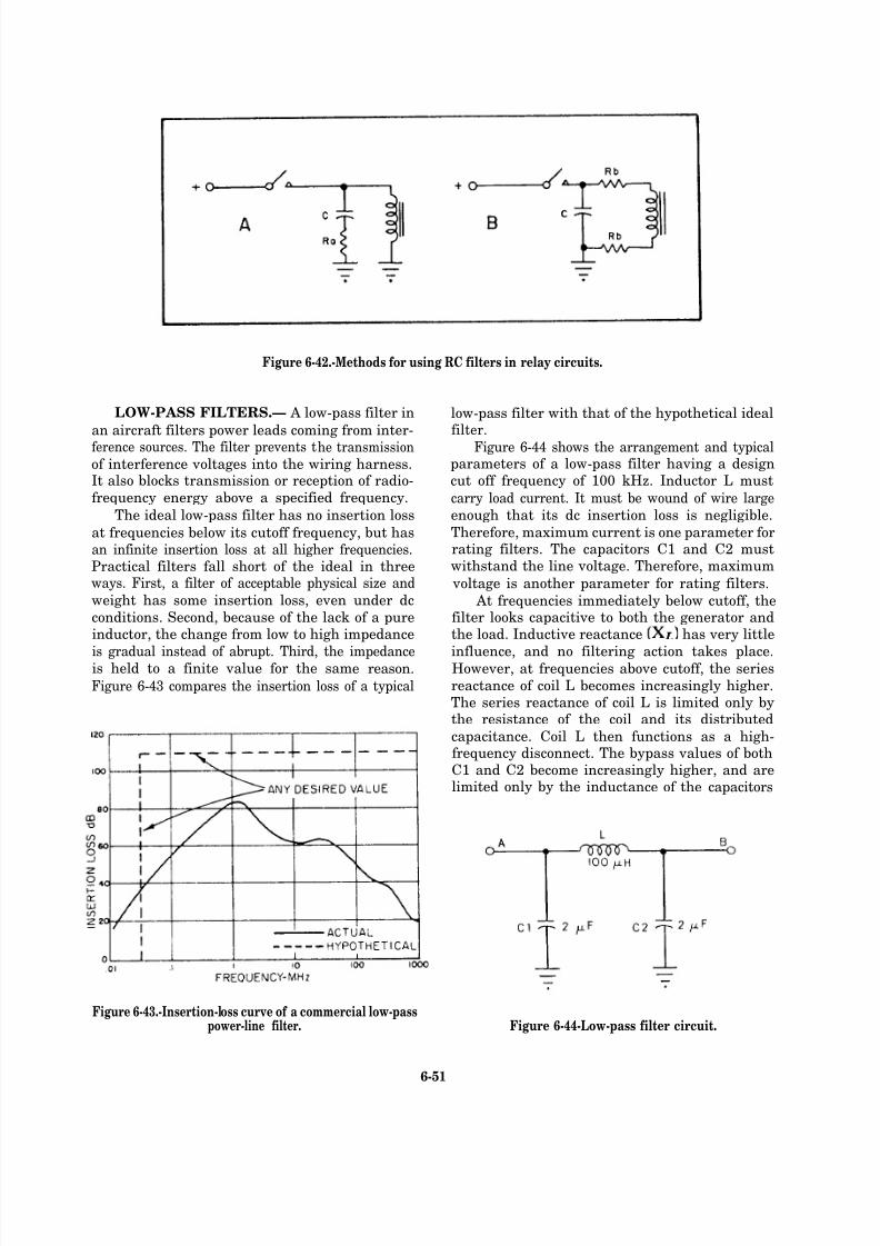
8/14/2019 US Navy Course NAVEDTRA 14028 - Aviation Electronics Technician-Basic
http://slidepdf.com/reader/full/us-navy-course-navedtra-14028-aviation-electronics-technician-basic 258/415
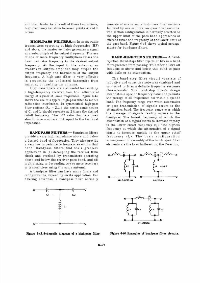
8/14/2019 US Navy Course NAVEDTRA 14028 - Aviation Electronics Technician-Basic
http://slidepdf.com/reader/full/us-navy-course-navedtra-14028-aviation-electronics-technician-basic 259/415

8/14/2019 US Navy Course NAVEDTRA 14028 - Aviation Electronics Technician-Basic
http://slidepdf.com/reader/full/us-navy-course-navedtra-14028-aviation-electronics-technician-basic 260/415
and the Pi-section configurations. (See figure
6-47.) For a more in-depth discussion on the various filters discussed in this chapter, you
should refer to Installation Practices for Electrical
and Electronic Wiring, NAVSHIPS 0967-000-0120,section 4.
Figure 6-47.-Examples of band-reject filter circuits.
Q24.
Q25.
Q26.
Q27.
Q28.
Q29.
Q30.
Q31.
Q32.
Q33.
Q34.
Name the two types of electrical noise
interference that enter aircraft receivers.
Of the three types of natural interference,
which is caused by radiation of stars?
Why are rotating electrical machines a
major source of receiver interference?
Does the size of an electric dc motor
determine its interference capability?
Name the types of equipment that can cause
pulse interference.
Describe rectification ripple frequency.
In aircraft wiring, the effect of induction
fields is reduced by using proper spacing
and coupling angle between wires. When isinterference coupling at its least?
What methods may be used to reduce radio
interference at the source?
Capacitors and capacitive filter circuits
make good filters for reducing and elimi-
nating noise. What characteristics are used
in selecting capacitors for filtering circuits
in aircraft?
How does an RC filter reduce interference?
How can you distinguish filter classes?
6-53
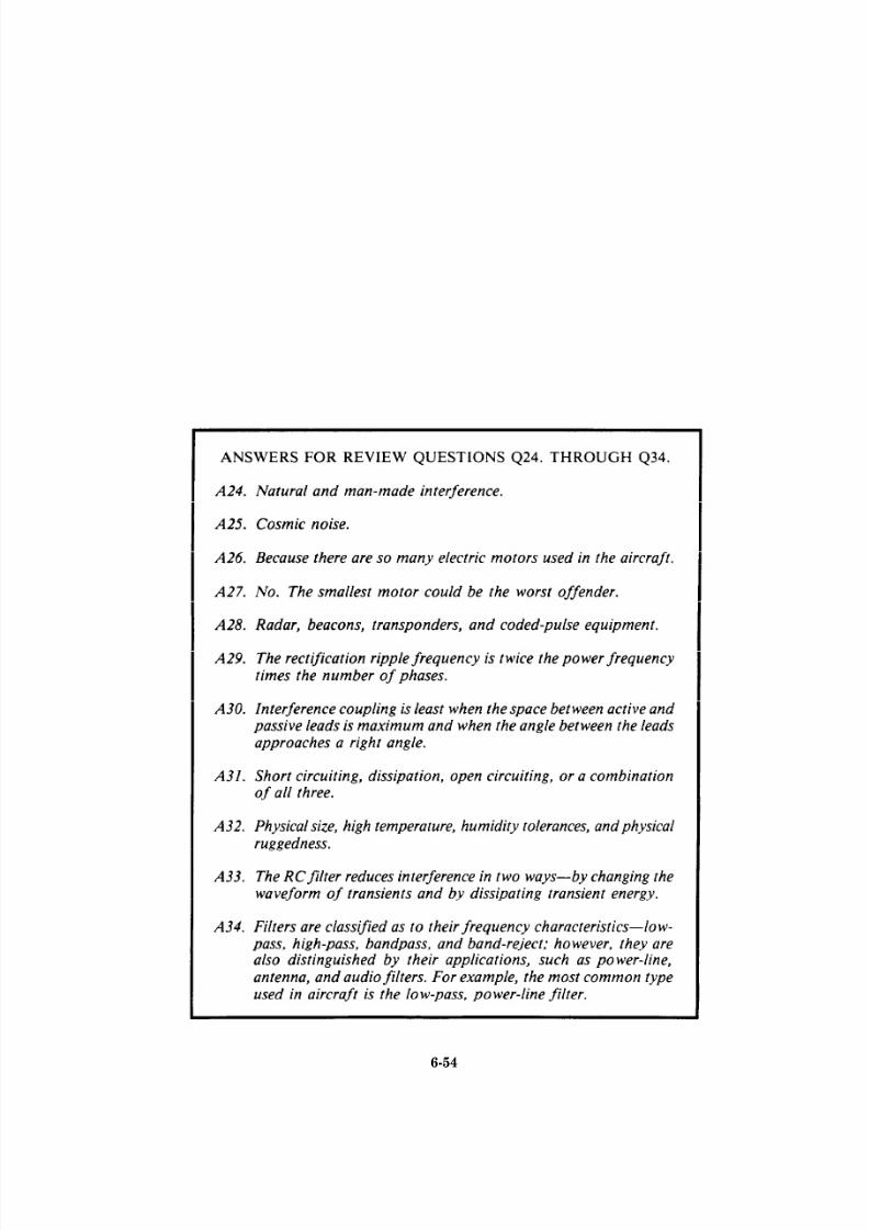
8/14/2019 US Navy Course NAVEDTRA 14028 - Aviation Electronics Technician-Basic
http://slidepdf.com/reader/full/us-navy-course-navedtra-14028-aviation-electronics-technician-basic 261/415
6-54

8/14/2019 US Navy Course NAVEDTRA 14028 - Aviation Electronics Technician-Basic
http://slidepdf.com/reader/full/us-navy-course-navedtra-14028-aviation-electronics-technician-basic 262/415
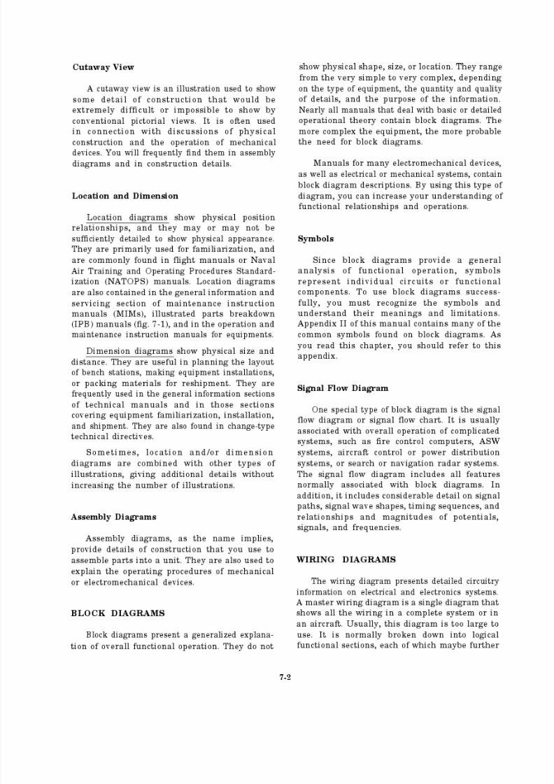
8/14/2019 US Navy Course NAVEDTRA 14028 - Aviation Electronics Technician-Basic
http://slidepdf.com/reader/full/us-navy-course-navedtra-14028-aviation-electronics-technician-basic 263/415

8/14/2019 US Navy Course NAVEDTRA 14028 - Aviation Electronics Technician-Basic
http://slidepdf.com/reader/full/us-navy-course-navedtra-14028-aviation-electronics-technician-basic 264/415
Figure 7-1.-IPB sample figure, radar control panal installation and stick assembly.
7-3
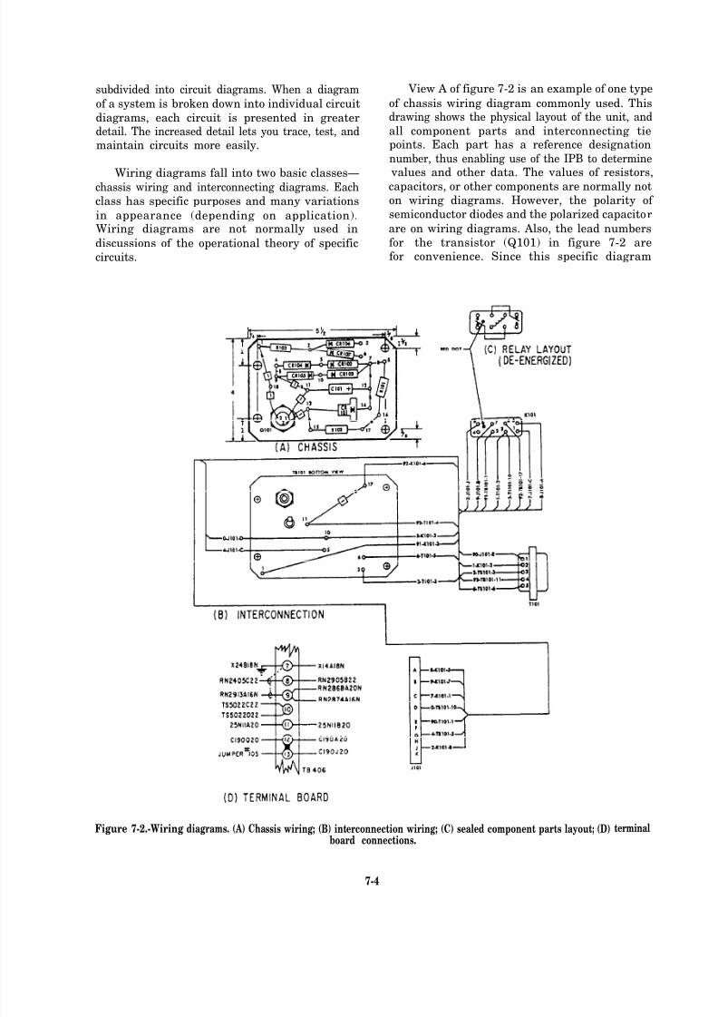
8/14/2019 US Navy Course NAVEDTRA 14028 - Aviation Electronics Technician-Basic
http://slidepdf.com/reader/full/us-navy-course-navedtra-14028-aviation-electronics-technician-basic 265/415
subdivided into circuit diagrams. When a diagram
of a system is broken down into individual circuit
diagrams, each circuit is presented in greaterdetail. The increased detail lets you trace, test, andmaintain circuits more easily.
Wiring diagrams fall into two basic classes—chassis wiring and interconnecting diagrams. Each
class has specific purposes and many variations
in appearance (depending on application).Wiring diagrams are not normally used in
discussions of the operational theory of specific
circuits.
Figure 7-2.-Wiring
View A of figure 7-2 is an example of one type
of chassis wiring diagram commonly used. Thisdrawing shows the physical layout of the unit, and
all component parts and interconnecting tiepoints. Each part has a reference designation
number, thus enabling use of the IPB to determine
values and other data. The values of resistors,capacitors, or other components are normally not
on wiring diagrams. However, the polarity of
semiconductor diodes and the polarized capacitor
are on wiring diagrams. Also, the lead numbers
forfor
the transistor (Q101) in figure 7-2 areconvenience. Since this specific diagram
diagrams. (A) Chassis wiring; (B) interconnection wiring; (C) sealed component parts layout;board connections.
(D) terminal
7-4
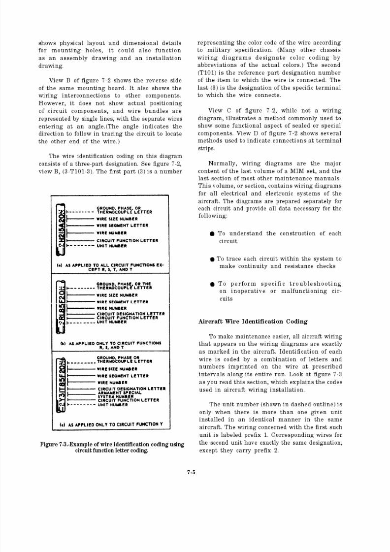
8/14/2019 US Navy Course NAVEDTRA 14028 - Aviation Electronics Technician-Basic
http://slidepdf.com/reader/full/us-navy-course-navedtra-14028-aviation-electronics-technician-basic 266/415

8/14/2019 US Navy Course NAVEDTRA 14028 - Aviation Electronics Technician-Basic
http://slidepdf.com/reader/full/us-navy-course-navedtra-14028-aviation-electronics-technician-basic 267/415
The circuit function letter identifies the basicfunction of the unit. Look at table 7-1. Note that
circuit function R, S, and T wiring may bear a
second letter to designate the functional
breakdown of the circuit.
On new aircraft, the equipment identificationcode replaces the circuit function letters R, S, T,
and Y. The equipment identification code is thepart of the AN nomenclature following thediagonal (/), excluding the hyphen (-) and suffixletters. For example, wires of an AN/APS-115(V)
unit will have an equipment identification code
of APS115. Those of an AN/ARC-52A unit willuse ARC52 (fig. 7-4), and those of an AN/MX-94
unit use MX94 as there equipment identificationcodes.
Each wire within a given circuit function group
has a separate wire number. Wires that have
segments of splices, plug and receptacle con-nectors, terminal strip tie points, etc., have a letter
segment designation. Passage through a switch,relay, circuit breaker, etc., requires assignment
of a new number.Wire size numbers identify the size of the wire
or cable, but are not on coaxial cables. Wire sizenumbers are replaced by a dash and coded
designator when part of a thermocouple arrange-ment.
A suffix is added to designate the phase (or
ground) in three-phase ac power wiring. A
thermocouple has a suffix that denotes the metal
element involved.
For further information on aircraft wiring
codes, you should refer to I nstallation Practices, Aircraft Electric and Electronic Wiring, NAVAIR01-1A-505.
Cable Construction
Cable construction diagrams present details
about the fabrication and construction of cables.These details usually include designation of the
type connectors or terminals, identification of wires for each terminal, and method of connectingwire to terminal. The details also include potting
requirements, length of wires, lacing or sleeving
specif ications, and any other specifications orspecial considerations.
Cable Routing
Diagrams of major systems usually include
an isometric shadow outline of the aircraft,showing the approximate location of equip-ment components and the physical routing of
Table 7-1.-Wiring Circuit Function Code
7-6

8/14/2019 US Navy Course NAVEDTRA 14028 - Aviation Electronics Technician-Basic
http://slidepdf.com/reader/full/us-navy-course-navedtra-14028-aviation-electronics-technician-basic 268/415
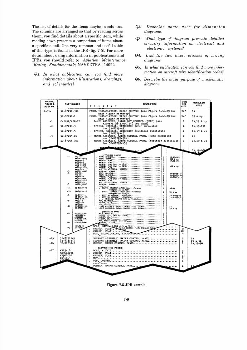
8/14/2019 US Navy Course NAVEDTRA 14028 - Aviation Electronics Technician-Basic
http://slidepdf.com/reader/full/us-navy-course-navedtra-14028-aviation-electronics-technician-basic 269/415
The list of details for the items maybe in columns. Q2.
The columns are arranged so that by reading across
them, you find details about a specific item, whilereading down presents a comparison of items about
Q3.
a specific detail. One very common and useful table
of this type is found in the IPB (fig. 7-5). For more
detail about using information in publications and Q4.
IPBs, you should refer to Aviation Maintenance Rating Fundamentals, NAVEDTRA 14022.Q5.
Q1. In what publication can you find more
information about illustrations, drawings, Q6.
and schematics?
Describe some uses for dimension
diagrams.
What type of diagram presents detailed
circuitry information on electrical and
electronic systems?
List the two basic classes of wiring
diagrams. In what publication can you find more infor-
mation on aircraft wire identification codes?
Describ e the major purpose of a schematic
diagram.
Figure 7-5.-IPB sample.
7-8
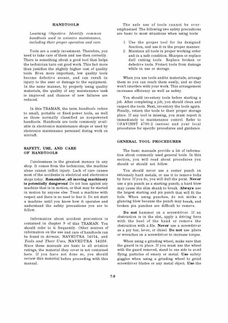
8/14/2019 US Navy Course NAVEDTRA 14028 - Aviation Electronics Technician-Basic
http://slidepdf.com/reader/full/us-navy-course-navedtra-14028-aviation-electronics-technician-basic 270/415
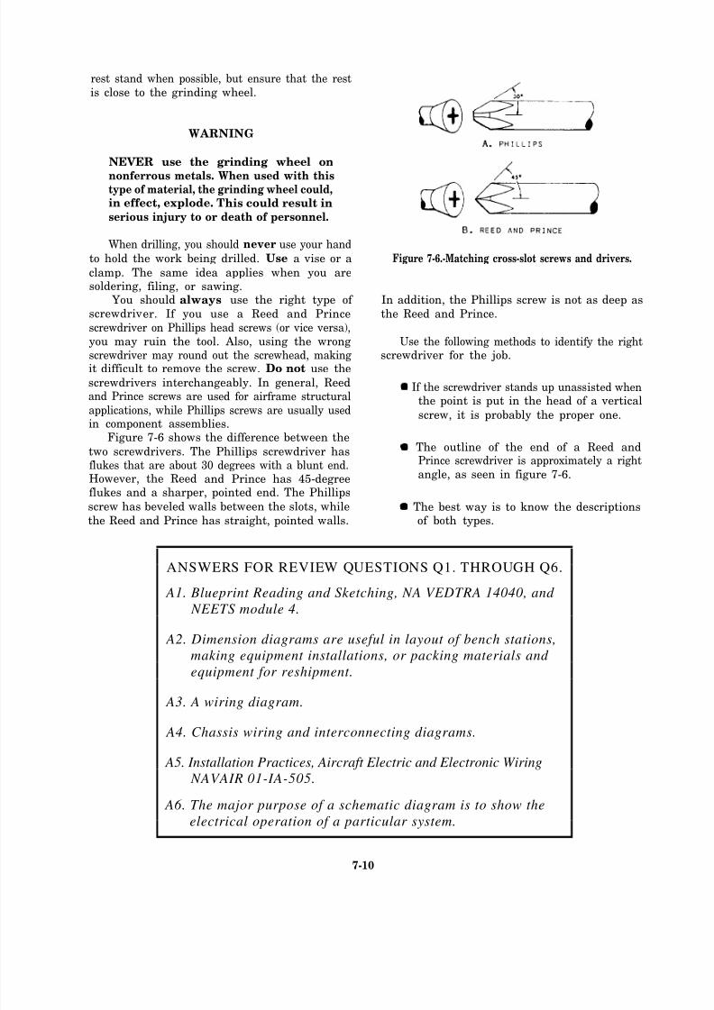
8/14/2019 US Navy Course NAVEDTRA 14028 - Aviation Electronics Technician-Basic
http://slidepdf.com/reader/full/us-navy-course-navedtra-14028-aviation-electronics-technician-basic 271/415
8/14/2019 US Navy Course NAVEDTRA 14028 - Aviation Electronics Technician-Basic
http://slidepdf.com/reader/full/us-navy-course-navedtra-14028-aviation-electronics-technician-basic 272/415
8/14/2019 US Navy Course NAVEDTRA 14028 - Aviation Electronics Technician-Basic
http://slidepdf.com/reader/full/us-navy-course-navedtra-14028-aviation-electronics-technician-basic 273/415
The three most commonly used torquewrenches are the deflecting-beam, dial-indicating,
and micrometer-setting types (fig. 7-7). Whenusing deflecting-beam and dial-indicating torquewrenches, you read the torque visually from
a dial or scale mounted on the handle of thewrench.
The most accurate and reliable torque wrenchis the micrometer-setting type. The next most
accurate and reliable is the dial-indicating type.The least accurate and reliable is the deflecting-
beam type. You should not use the deflecting-
beam type (because of the high probability
of operator error) unless it is absolutely
necessary.
To use the micrometer-setting torque wrench,
unlock the grip and adjust the handle to thedesired setting on the micrometer-type scale, and
then relock the grip. Install the required socketor adapter to the square drive of the handle. Placethe wrench assembly on the nut or bolt and pull
in a clockwise direction with a smooth, steady
motion. (A fast or jerky motion results in an
improperly torqued unit. ) When the appliedtorque reaches the torque value indicated on the
handle setting, the handle automatically releases
or “breaks” and moves freely for a short distance.The release and free travel is easy to feel, sothere is no doubt when the torquing process is
complete.
To make sure the correct amount of torque
is gotten on fasteners, all torque handles
require periodic testing under the metrologyprogram.
You should take the f ollowing precautions
when using torque wrenches.
Always ensure proper calibration.
Do not use the torque wrench as a
hammer.
When using the micrometer-setting type,
do not move the setting handle below the
lowest torque setting. However, youshould place it at its lowest setting beforereturning it to storage.
Do not use the torque wrench to apply
greater amounts of torque than its rated
capacity.
Figure 7-7.-Torque wrenches.
ANSWER FOR REVIEW QUESTION Q7.
A7. TRAMAN, NAVEDTRA 1 2000, and Tools and Their Uses, NAVEDTRA 14256.
7-12

8/14/2019 US Navy Course NAVEDTRA 14028 - Aviation Electronics Technician-Basic
http://slidepdf.com/reader/full/us-navy-course-navedtra-14028-aviation-electronics-technician-basic 274/415
• Do not use the torque wrench to break loosebolts.
• Never store a torque wrench in a toolbox orin an area that may cause damage to it.
• Do not drop the wrench because it will affect
its accuracy.
RELAY TOOLS
You may damage or ruin relay tools if you use
sandpaper or emery cloth to clean the contactpoints. Use of abrasives as a cleaner causes thecent acts to bend. Trying to straighten them with
long-nose pliers causes further damage, eventuallyrequiring replacement of the relays. You can avoidthe whole problem by using a burnishing tool to
clean dirty contact points. Figure 7-8, view A,shows the use of a burnishing tool on a relay.Burnishing tools are available through normalsupply channels. Before using this tool, you should
clean it thoroughly with alcohol; do not touch thetool surface with your fingers before use.Burnishing burned and pitted contacts will notrepair them. You must replace burned and pitted
contacts.
Another tool useful in relay maintenance is a
point bender (fig. 7-8, view B). It can help tostraighten bent relay contacts. You can make thistool locally using a 0.12-inch diameter rod stock,
shaping it as shown in figure 7-8.
WIRE AND CABLE TOOLS
An innovation in electrical connectors is the
taper pin electrical connector for aircraft. Thetaper pin works on the principle of driving a taperwedge into a tapered hole, and depends on friction
to keep the pin in the hole. The taper pinconnector makes a very good electrical andmechanical connection because of the high metal-to- metal contact pressure developed during thedri ving action of the insertion tool. Taper pins let
you make circuit changes quickly and easilywithout using a soldering iron. Tests show that
vibration and corrosion over time can improve theelectrical continuity and increase the mechanicalpulling force required to remove a taper pin.
Another advantage of taper pins is the
accessibility of test points for voltage and circuitcontinuity checks.
Figure 7-8.-View A, burnishing tool; view B, point
bender.
7-13
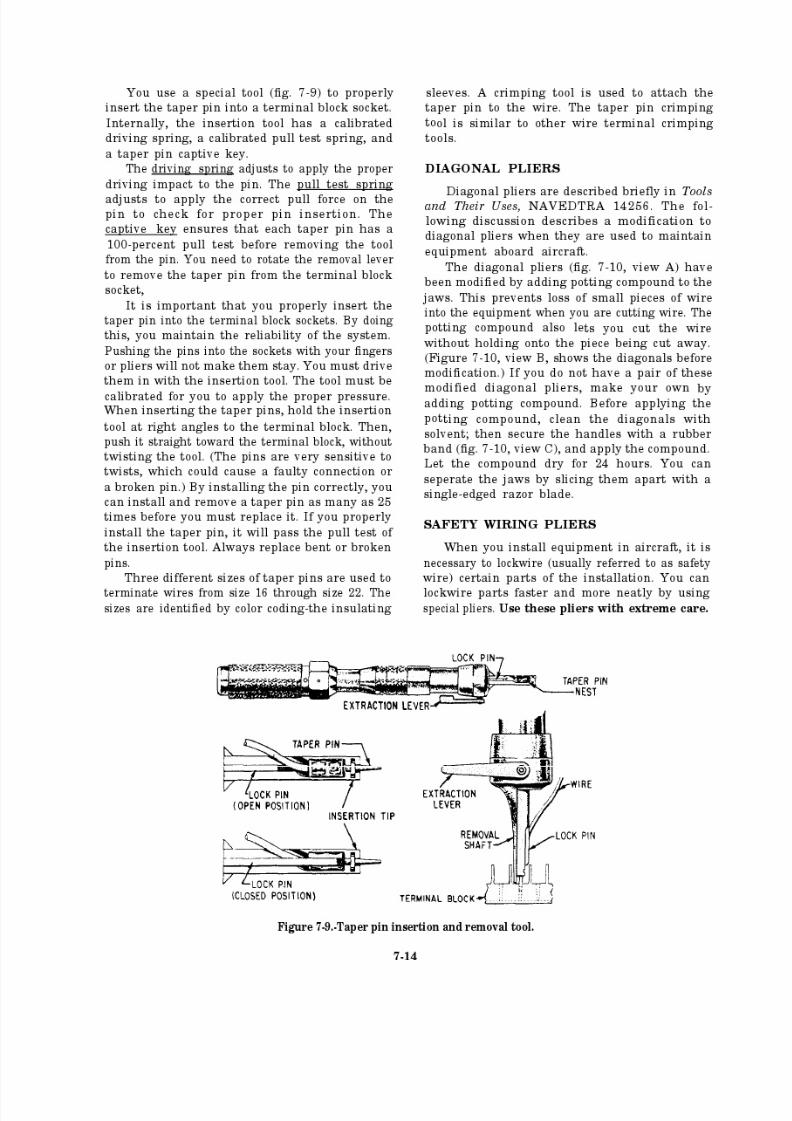
8/14/2019 US Navy Course NAVEDTRA 14028 - Aviation Electronics Technician-Basic
http://slidepdf.com/reader/full/us-navy-course-navedtra-14028-aviation-electronics-technician-basic 275/415
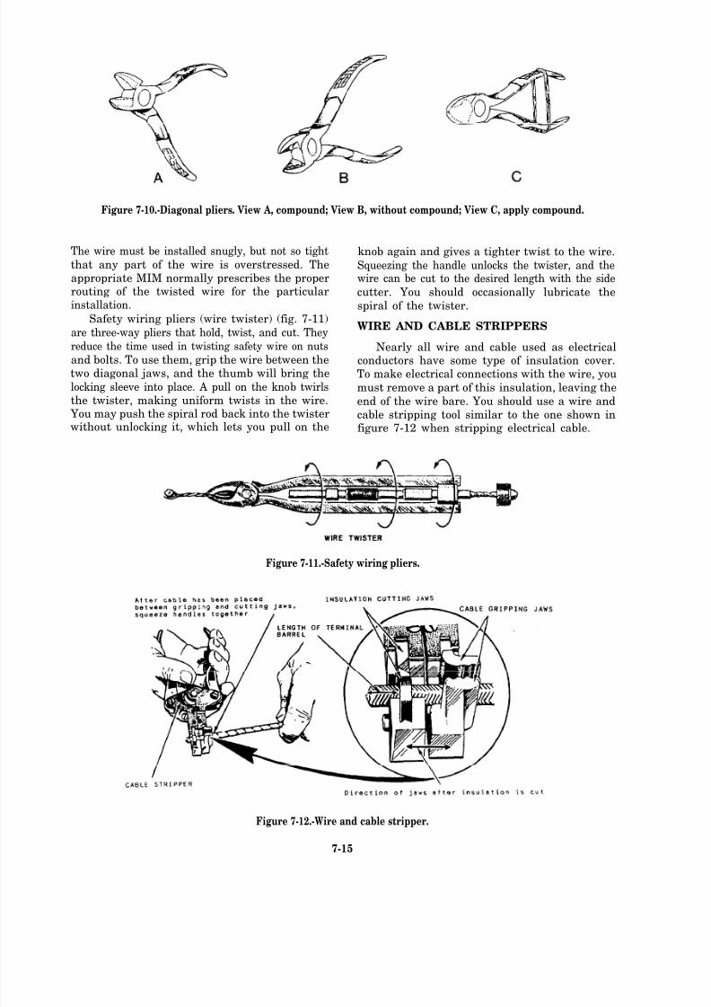
8/14/2019 US Navy Course NAVEDTRA 14028 - Aviation Electronics Technician-Basic
http://slidepdf.com/reader/full/us-navy-course-navedtra-14028-aviation-electronics-technician-basic 276/415
Figure 7-10.-Diagonal pliers. View A, compound; View B, without compound; View C, apply compound.
The wire must be installed snugly, but not so tight
that any part of the wire is overstressed. Theappropriate MIM normally prescribes the properrouting of the twisted wire for the particularinstallation.
Safety wiring pliers (wire twister) (fig. 7-11)
are three-way pliers that hold, twist, and cut. Theyreduce the time used in twisting safety wire on nuts
and bolts. To use them, grip the wire between thetwo diagonal jaws, and the thumb will bring the
locking sleeve into place. A pull on the knob twirlsthe twister, making uniform twists in the wire. You may push the spiral rod back into the twisterwithout unlocking it, which lets you pull on the
knob again and gives a tighter twist to the wire.
Squeezing the handle unlocks the twister, and thewire can be cut to the desired length with the side
cutter. You should occasionally lubricate the
spiral of the twister.
WIRE AND CABLE STRIPPERS
Nearly all wire and cable used as electricalconductors have some type of insulation cover.To make electrical connections with the wire, you
must remove a part of this insulation, leaving the
end of the wire bare. You should use a wire andcable stripping tool similar to the one shown infigure 7-12 when stripping electrical cable.
Figure 7-11.-Safety wiring pliers.
Figure 7-12.-Wire and cable stripper.
7-15
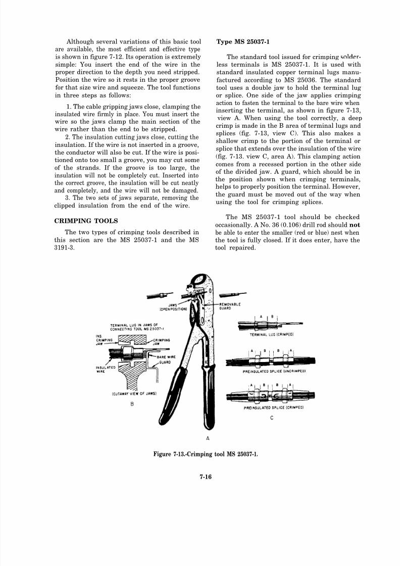
8/14/2019 US Navy Course NAVEDTRA 14028 - Aviation Electronics Technician-Basic
http://slidepdf.com/reader/full/us-navy-course-navedtra-14028-aviation-electronics-technician-basic 277/415
Although several variations of this basic toolare available, the most efficient and effective typeis shown in figure 7-12. Its operation is extremely
simple: You insert the end of the wire in theproper direction to the depth you need stripped.
Position the wire so it rests in the proper groove
for that size wire and squeeze. The tool functions
in three steps as follows:
1. The cable gripping jaws close, clamping theinsulated wire firmly in place. You must insert thewire so the jaws clamp the main section of thewire rather than the end to be stripped.
2. The insulation cutting jaws close, cutting the
insulation. If the wire is not inserted in a groove,
the conductor will also be cut. If the wire is posi-tioned onto too small a groove, you may cut some
of the strands. If the groove is too large, the
insulation will not be completely cut. Inserted intothe correct groove, the insulation will be cut neatlyand completely, and the wire will not be damaged.
3. The two sets of jaws separate, removing theclipped insulation from the end of the wire.
CRIMPING TOOLS
The two types of crimping tools described in
this section are the MS 25037-1 and the MS
3191-3.
Type MS 25037-1
The standard tool issued for crimpingless terminals is MS 25037-1. It is used with
standard insulated copper terminal lugs manu-
factured according to MS 25036. The standard
tool uses a double jaw to hold the terminal lugor splice. One side of the jaw applies crimping
action to fasten the terminal to the bare wire wheninserting the terminal, as shown in figure 7-13,
view A. When using the tool correctly, a deep
crimp is made in the B area of terminal lugs andsplices (fig. 7-13, view C). This also makes a
shallow crimp to the portion of the terminal or
splice that extends over the insulation of the wire
(fig. 7-13. view C, area A). This clamping action
comes from a recessed portion in the other sideof the divided jaw. A guard, which should be inthe position shown when crimping terminals,helps to properly position the terminal. However,
the guard must be moved out of the way whenusing the tool for crimping splices.
The MS 25037-1 tool should be checked
occasionally. A No. 36 (0.106) drill rod should not
be able to enter the smaller (red or blue) nest whenthe tool is fully closed. If it does enter, have thetool repaired.
Figure 7-13.-Crimping tool MS 25037-1.
7-16

8/14/2019 US Navy Course NAVEDTRA 14028 - Aviation Electronics Technician-Basic
http://slidepdf.com/reader/full/us-navy-course-navedtra-14028-aviation-electronics-technician-basic 278/415
Instruction in the proper crimping procedureshould be given to all who need to make solderlessterminal connections. Installation Practices, Aircraft
Electric and Electronic Wiring, NAVAIR 01-1A-505,contains detailed procedures for using manysolderless connector tools.
Type MS 3191-3
MS 3191-3 is the latest standard crimping tooldesigned specifically for use with MS 3191 contactsfor electrical connectors. It features interchangeableheads that fit various size terminals. You may use itwith the turret (fig. 7-14, view A) for normal use orwithout the turret (fig. 7-14, view B) for eyeballcrimping (when material alignment does not allowuse of the turret).
Before you use the tool, you must select thecorrect position on the positioner head and also on
the indentor gap selector plate. To release the turret
for indexing, press the trigger and the spring-loaded
turret snaps out to its indexing position. Select thedesired position from the color-coded nameplate, androtate the turret to align the selected positioner with
the index. Depress the turret until flush, and itautomatically locks into place. To prevent f urtherindexing, insert the lockwire through the hole in thetrigger.
To crimp a terminal, select the proper size and
type terminal. Insert the prepared wire into thecontact pocket until the wire seats on the bottom. Thewire should be visible through the inspection hole
and the insulation should enter the contact insulationsupport. Then, insert the contact and wire into theterminal crimping tool, making sure that the contact
seats properly in the positioner. Close the crimpingtool handles to crimp the contact and wire. At thecompletion of the stroke, the ratchet releases, and
you can open the handles and remove the crimpedcontact from the tool.
Figure 7-14.-Crimping tool MS 3191-3.
7-17
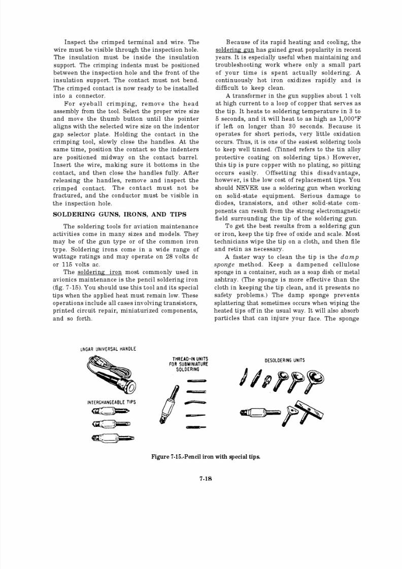
8/14/2019 US Navy Course NAVEDTRA 14028 - Aviation Electronics Technician-Basic
http://slidepdf.com/reader/full/us-navy-course-navedtra-14028-aviation-electronics-technician-basic 279/415
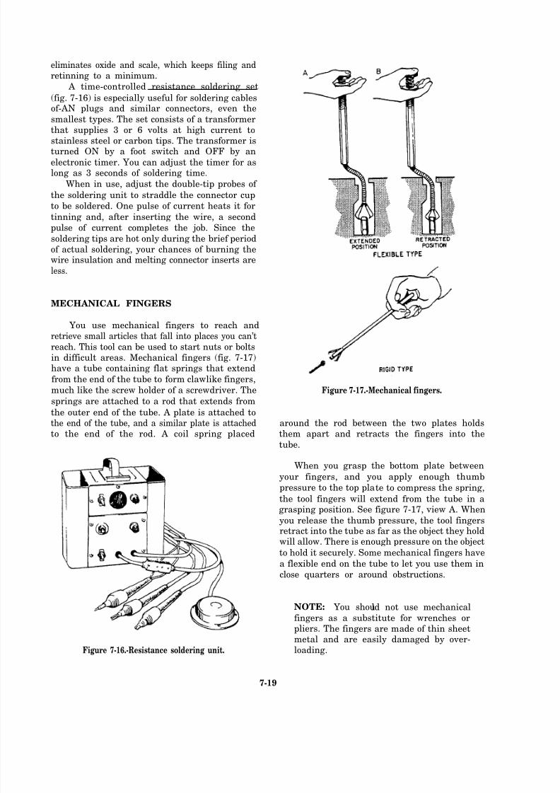
8/14/2019 US Navy Course NAVEDTRA 14028 - Aviation Electronics Technician-Basic
http://slidepdf.com/reader/full/us-navy-course-navedtra-14028-aviation-electronics-technician-basic 280/415
eliminates oxide and scale, which keeps filing andretinning to a minimum.
A time-controlled resistance soldering set
(fig. 7-16) is especially useful for soldering cablesof-AN plugs and similar connectors, even the
smallest types. The set consists of a transformerthat supplies 3 or 6 volts at high current to
stainless steel or carbon tips. The transformer isturned ON by a foot switch and OFF by an
electronic timer. You can adjust the timer for aslong as 3 seconds of soldering time.
When in use, adjust the double-tip probes of
the soldering unit to straddle the connector cup
to be soldered. One pulse of current heats it for
tinning and, after inserting the wire, a second
pulse of current completes the job. Since the
soldering tips are hot only during the brief periodof actual soldering, your chances of burning thewire insulation and melting connector inserts are
less.
MECHANICAL FINGERS
You use mechanical fingers to reach andretrieve small articles that fall into places you can’t
reach. This tool can be used to start nuts or boltsin difficult areas. Mechanical fingers (fig. 7-17)have a tube containing flat springs that extend
from the end of the tube to form clawlike fingers,
much like the screw holder of a screwdriver. The
springs are attached to a rod that extends from
the outer end of the tube. A plate is attached tothe end of the tube, and a similar plate is attachedto the end of the rod. A coil spring placed
Figure 7-16.-Resistance soldering unit.
Figure 7-17.-Mechanical fingers.
around the rod between the two plates holdsthem apart and retracts the fingers into the
tube.
When you grasp the bottom plate between
your fingers, and you apply enough thumb
pressure to the top plate to compress the spring,
the tool fingers will extend from the tube in agrasping position. See figure 7-17, view A. When
you release the thumb pressure, the tool fingersretract into the tube as far as the object they holdwill allow. There is enough pressure on the object
to hold it securely. Some mechanical fingers havea flexible end on the tube to let you use them in
close quarters or around obstructions.
NOTE: You should not use mechanical
fingers as a substitute for wrenches orpliers. The fingers are made of thin sheetmetal and are easily damaged by over-loading.
7-19

8/14/2019 US Navy Course NAVEDTRA 14028 - Aviation Electronics Technician-Basic
http://slidepdf.com/reader/full/us-navy-course-navedtra-14028-aviation-electronics-technician-basic 281/415

8/14/2019 US Navy Course NAVEDTRA 14028 - Aviation Electronics Technician-Basic
http://slidepdf.com/reader/full/us-navy-course-navedtra-14028-aviation-electronics-technician-basic 282/415
Q10.
Q11.
Q12.
Q13.
What special tool will hold, twist, and cut?
Describe the MS 3191-3 crimping tool.
What is the most common soldering iron
used in avionics maintenance?
Where can you find the special tools for fiber optic repair?
AIRCRAFT HARDWARE AND
CONSUMABLE MATERIALS
Learning Objective: Identify aircraft
hardware and consumable materials, and
recognize their use in the maintenance of
integral aircraft parts and substitution of
parts.
As a technician, you should have knowledge
of certain items of hardware and consumablematerial. Hardware and material are used for
installing equipment and repairing installedequipment. You should always use the properparts and material. The applicable MIMs specify
items of hardware and material necessary for
aircraft maintenance. If you find you must make
substitutions, make sure that the substituted itemis satisfactory.
MOUNTING PARTS
The same mounting parts that were removed
from an installation should not always be usedwhen you reinstall equipment. Before reinstalling
the same items, inspect them to make sure thatthey are the specified parts and that they are notdefective or damaged. You must also determineif instructions forbid their reuse. If not forbidden,
then, and only then, reinstall the removed parts.
Information on the use of mounting parts,
such as screws. nuts. bolts, and washers, is of a
general nature. You should follow establisheddoctrine for their use. A valuable source of
detailed information is Aircraft Structural
Hardware for Aircraft Repair, NAVAIR 01-1A-8.
TURNLOCK FASTENERS
Turnlock fasteners secure inspection plates,
doors, and other removable panels on aircraft.
Turnlock fasteners are also referred to by such
terms as quick-opening, quick-action, and stress
panel fasteners. The most desirable feature of these fasteners is that they let you quickly andeasily remove access panels for inspection and
servicing purposes.Turnlock fasteners are manufactured and
supplied by a number of manufacturers under various trade names. Some of the more commonly
used fasteners are the Camloc stress panel fastener
and the Airloc fastener. For a discussion of otherturnlock fasteners, you should refer to Airman,
NAVEDTRA 14014.
Camloc Stress Panel Fasteners
The Camloc stress panel fastener (fig. 7-21)is a high-strength, quick-release, rotary-type
Figure 7-21.-Camloc stress panel fasteners.
7-21
8/14/2019 US Navy Course NAVEDTRA 14028 - Aviation Electronics Technician-Basic
http://slidepdf.com/reader/full/us-navy-course-navedtra-14028-aviation-electronics-technician-basic 283/415
fastener. You may find them on flat or curved
inside or outside panels. The fastener may have
either a flush or a nonflush stud. The studs areheld in the panel with flat or cone-shaped washers,
the latter being used with flush fasteners indimpled holes.
You can tell this fastener from screws by the
deep No. 2 Phillips recess in the stud head andby the bushing in which the stud is installed. A
threaded insert in the receptacle provides an
adjustable locking device. As you insert the stud
and turn it counterclockwise one-half turn ormore, it screws out the insert enough to permit
the stud key to engage the insert cam when youturn it clockwise. Rotating the stud clockwiseone-fourth turn engages the insert, and continuedrotation screws the insert in, tightening the
fastener. Turning the stud one-fourth turn
counterclockwise will then release the stud, butit will not screw the insert out far enough to permit
reengagement in installation. It is necessary toturn the stud at least one-half turn counter-clockwise to reset the insert.
To unlock the stress panel fastener and resetit in the same operation, you should use aNo. 2 Phillips screwdriver to turn the stud
counterclockwise one-half turn or more. Do not
turn the stud past the stop.
CAUTION
Do not use a power screwdriver on this
To lock the stress panel fastener, you should
use a No. 2 Phillips screwdriver. Push the studin, and turn clockwise until you feel increasedtorque; then continue turning until the fasteneris tight.
When installing a large panel, it may be
necessary to engage all the fasteners before
tightening them. This is done by pushing each studin and turning it clockwise one-fourth turn. The
stud should engage the receptacle, but it should
remain loose. If the stud does not engage, it will
pop out, indicating that the insert must be resetby turning the stud counterclockwise one-half turnor more.
Airloc Fastener
The Airloc fastener consists of a stud, a stud
cross pin, and a receptacle (fig. 7-22). The studis attached to the access cover and is held in place
by the cross pin. The receptacle is riveted to theaccess cover frame. A quarter turn of thestud (clockwise) locks the fastener in place.Turning the stud counterclockwise unlocks the
fastener.
THREADED FASTENERS
fastener. text.
For a discussion of threaded fasteners, refer
to Airman, NAVEDTRA 14014. However, a brief
discussion of Torq-set screws is included in this
7-22
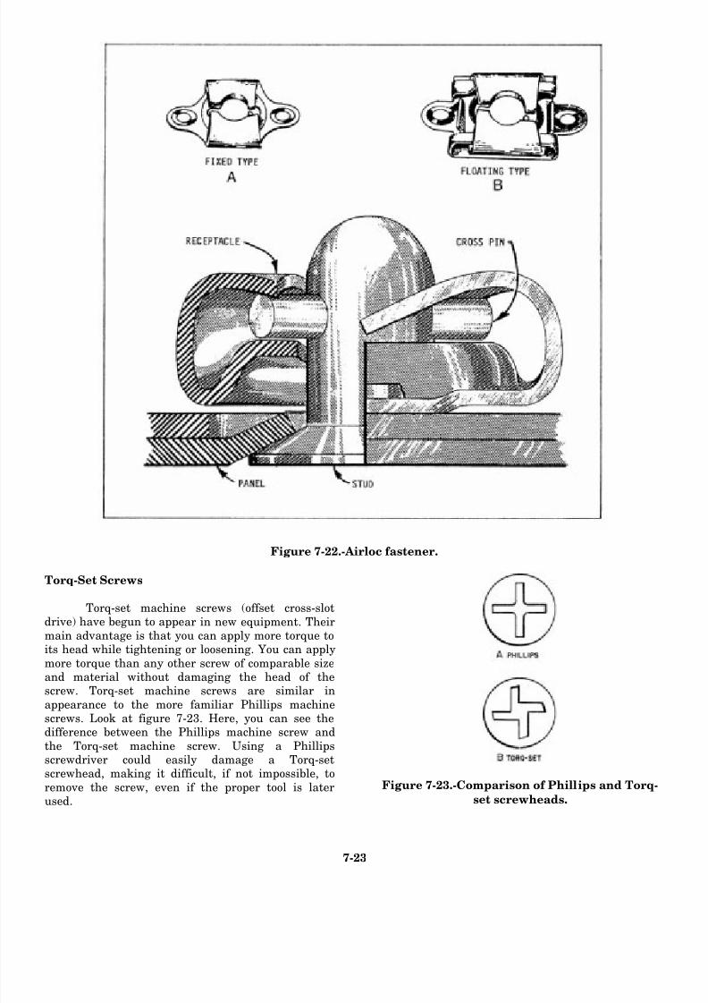
8/14/2019 US Navy Course NAVEDTRA 14028 - Aviation Electronics Technician-Basic
http://slidepdf.com/reader/full/us-navy-course-navedtra-14028-aviation-electronics-technician-basic 284/415
Figure 7-22.-Airloc fastener.
Torq-Set Screws
Torq-set machine screws (offset cross-slotdrive) have begun to appear in new equipment. Theirmain advantage is that you can apply more torque toits head while tightening or loosening. You can apply
more torque than any other screw of comparable sizeand material without damaging the head of thescrew. Torq-set machine screws are similar in
appearance to the more familiar Phillips machinescrews. Look at figure 7-23. Here, you can see thedifference between the Phillips machine screw and
the Torq-set machine screw. Using a Phillipsscrewdriver could easily damage a Torq-setscrewhead, making it difficult, if not impossible, to
remove the screw, even if the proper tool is laterused.
Figure 7-23.-Comparison of Phillips and Torq-
set screwheads.
7-23
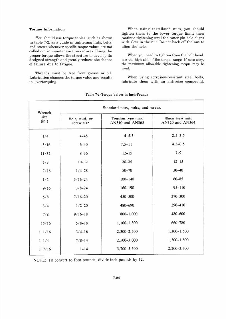
8/14/2019 US Navy Course NAVEDTRA 14028 - Aviation Electronics Technician-Basic
http://slidepdf.com/reader/full/us-navy-course-navedtra-14028-aviation-electronics-technician-basic 285/415
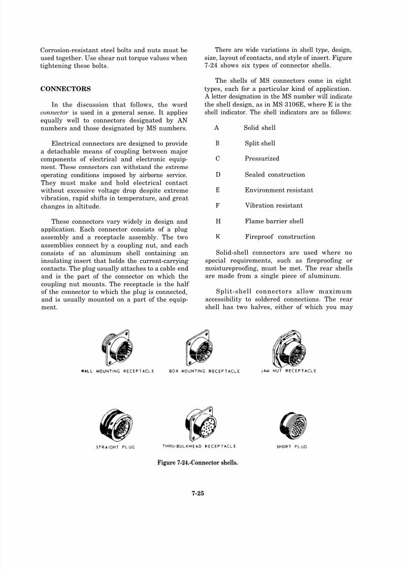
8/14/2019 US Navy Course NAVEDTRA 14028 - Aviation Electronics Technician-Basic
http://slidepdf.com/reader/full/us-navy-course-navedtra-14028-aviation-electronics-technician-basic 286/415
Corrosion-resistant steel bolts and nuts must be
used together. Use shear nut torque values whentightening these bolts.
CONNECTORS
In the discussion that follows, the wordconnector is used in a general sense. It applies
equally well to connectors designated by AN
numbers and those designated by MS numbers.
Electrical connectors are designed to provide
a detachable means of coupling between major
components of electrical and electronic equip-
ment. These connectors can withstand the extreme
operating conditions imposed by airborne service.
They must make and hold electrical contactwithout excessive voltage drop despite extreme
vibration, rapid shifts in temperature, and greatchanges in altitude.
These connectors vary widely in design and
application. Each connector consists of a plug
assembly and a receptacle assembly. The two
assemblies connect by a coupling nut, and each
consists of an aluminum shell containing aninsulating insert that holds the current-carryingcontacts. The plug usually attaches to a cable end
and is the part of the connector on which the
coupling nut mounts. The receptacle is the half of the connector to which the plug is connected,
and is usually mounted on a part of the equip-ment.
There are wide variations in shell type, design,
size, layout of contacts, and style of insert. Figure7-24 shows six types of connector shells.
The shells of MS connectors come in eight
types, each for a particular kind of application.
A letter designation in the MS number will indicatethe shell design, as in MS 3106E, where E is the
shell indicator. The shell indicators are as follows:
A Solid shell
B Split shell
C Pressurized
D Sealed construction
E Environment resistant
F Vibration resistant
H Flame barrier shell
K Fireproof construction
Solid-shell connectors are used where no
special requirements, such as fireproofing ormoistureproofing, must be met. The rear shellsare made from a single piece of aluminum.
Split-shell connectors allow maximum
accessibility to soldered connections. The rearshell has two halves, either of which you may
Figure 7-24.-Connector shells.
7-25

8/14/2019 US Navy Course NAVEDTRA 14028 - Aviation Electronics Technician-Basic
http://slidepdf.com/reader/full/us-navy-course-navedtra-14028-aviation-electronics-technician-basic 287/415

8/14/2019 US Navy Course NAVEDTRA 14028 - Aviation Electronics Technician-Basic
http://slidepdf.com/reader/full/us-navy-course-navedtra-14028-aviation-electronics-technician-basic 288/415
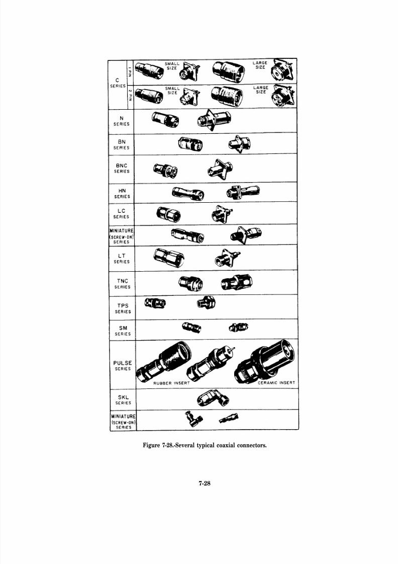
8/14/2019 US Navy Course NAVEDTRA 14028 - Aviation Electronics Technician-Basic
http://slidepdf.com/reader/full/us-navy-course-navedtra-14028-aviation-electronics-technician-basic 289/415
Figure 7-28.-Several typical coaxial connectors.
7-28
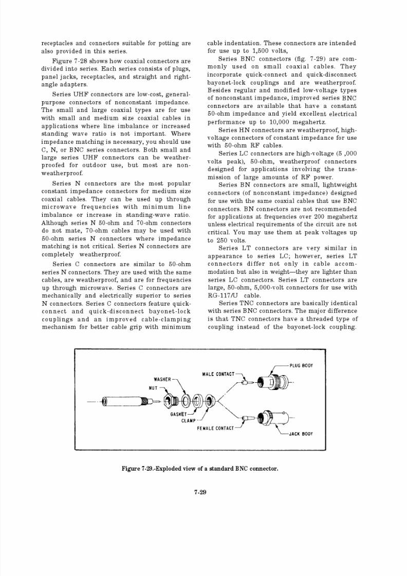
8/14/2019 US Navy Course NAVEDTRA 14028 - Aviation Electronics Technician-Basic
http://slidepdf.com/reader/full/us-navy-course-navedtra-14028-aviation-electronics-technician-basic 290/415
8/14/2019 US Navy Course NAVEDTRA 14028 - Aviation Electronics Technician-Basic
http://slidepdf.com/reader/full/us-navy-course-navedtra-14028-aviation-electronics-technician-basic 291/415
8/14/2019 US Navy Course NAVEDTRA 14028 - Aviation Electronics Technician-Basic
http://slidepdf.com/reader/full/us-navy-course-navedtra-14028-aviation-electronics-technician-basic 292/415
8/14/2019 US Navy Course NAVEDTRA 14028 - Aviation Electronics Technician-Basic
http://slidepdf.com/reader/full/us-navy-course-navedtra-14028-aviation-electronics-technician-basic 293/415

8/14/2019 US Navy Course NAVEDTRA 14028 - Aviation Electronics Technician-Basic
http://slidepdf.com/reader/full/us-navy-course-navedtra-14028-aviation-electronics-technician-basic 294/415

8/14/2019 US Navy Course NAVEDTRA 14028 - Aviation Electronics Technician-Basic
http://slidepdf.com/reader/full/us-navy-course-navedtra-14028-aviation-electronics-technician-basic 295/415
7-34
8/14/2019 US Navy Course NAVEDTRA 14028 - Aviation Electronics Technician-Basic
http://slidepdf.com/reader/full/us-navy-course-navedtra-14028-aviation-electronics-technician-basic 296/415
8/14/2019 US Navy Course NAVEDTRA 14028 - Aviation Electronics Technician-Basic
http://slidepdf.com/reader/full/us-navy-course-navedtra-14028-aviation-electronics-technician-basic 297/415
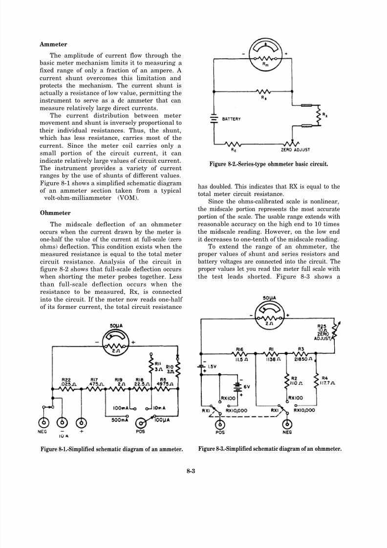
8/14/2019 US Navy Course NAVEDTRA 14028 - Aviation Electronics Technician-Basic
http://slidepdf.com/reader/full/us-navy-course-navedtra-14028-aviation-electronics-technician-basic 298/415
Ammeter
The amplitude of current flow through thebasic meter mechanism limits it to measuring a
fixed range of only a fraction of an ampere. A
current shunt overcomes this limitation andprotects the mechanism. The current shunt is
actually a resistance of low value, permitting theinstrument to serve as a dc ammeter that can
measure relatively large direct currents.The current distribution between meter
movement and shunt is inversely proportional to
their individual resistances. Thus, the shunt,which has less resistance, carries most of the
current. Since the meter coil carries only a
small portion of the circuit current, it can
indicate relatively large values of circuit current.The instrument provides a variety of currentranges by the use of shunts of different values.
Figure 8-1 shows a simplified schematic diagram
of an ammeter section taken from a typical volt-ohm-milliammeter (VOM).
Ohmmeter
The midscale deflection of an ohmmeter
occurs when the current drawn by the meter isone-half the value of the current at full-scale (zeroohms) deflection. This condition exists when themeasured resistance is equal to the total meter
circuit resistance. Analysis of the circuit infigure 8-2 shows that full-scale deflection occurswhen shorting the meter probes together. Less
than full-scale deflection occurs when the
resistance to be measured, Rx, is connected
into the circuit. If the meter now reads one-half of its former current, the total circuit resistance
Figure 8-1.-Simplified schematic diagram of an ammeter.
Figure 8-2.-Series-type ohmmeter basic circuit.
has doubled. This indicates that RX is equal to the
total meter circuit resistance.Since the ohms-calibrated scale is nonlinear,
the midscale portion represents the most accurate
portion of the scale. The usable range extends with
reasonable accuracy on the high end to 10 times
the midscale reading. However, on the low end
it decreases to one-tenth of the midscale reading.To extend the range of an ohmmeter, the
proper values of shunt and series resistors and
battery voltages are connected into the circuit. Theproper values let you read the meter full scale with
the test leads shorted. Figure 8-3 shows a
Figure 8-3.-Simplified schematic diagram of an ohmmeter.
8-3
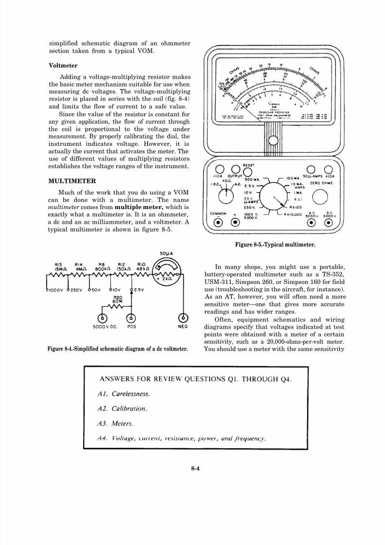
8/14/2019 US Navy Course NAVEDTRA 14028 - Aviation Electronics Technician-Basic
http://slidepdf.com/reader/full/us-navy-course-navedtra-14028-aviation-electronics-technician-basic 299/415
simplified schematic diagram of an ohmmeter
section taken from a typical VOM.
Voltmeter
Adding a voltage-multiplying resistor makesthe basic meter mechanism suitable for use whenmeasuring dc voltages. The voltage-multiplyingresistor is placed in series with the coil (fig. 8-4)
and limits the flow of current to a safe value.
Since the value of the resistor is constant forany given application, the flow of current through
the coil is proportional to the voltage undermeasurement. By properly calibrating the dial, the
instrument indicates voltage. However, it is
actually the current that activates the meter. Theuse of different values of multiplying resistors
establishes the voltage ranges of the instrument.
MULTIMETER
Much of the work that you do using a VOMcan be done with a multimeter. The namemultimeter comes from multiple meter, which isexactly what a multimeter is. It is an ohmmeter,
a dc and an ac milliammeter, and a voltmeter. A
typical multimeter is shown in figure 8-5.
Figure 8-5.-Typical multimeter.
In many shops, you might use a portable,battery-operated multimeter such as a TS-352,
USM-311, Simpson 260, or Simpson 160 for fielduse (troubleshooting in the aircraft, for instance).
As an AT, however, you will often need a more
sensitive meter—one that gives more accurate
readings and has wider ranges.
Often, equipment schematics and wiringdiagrams specify that voltages indicated at testpoints were obtained with a meter of a certainsensitivity, such as a 20,000-ohms-per-volt meter.
Figure 8-4.-Simplified schematic diagram of a dc voltmeter. You should use a meter with the same sensitivity
8-4
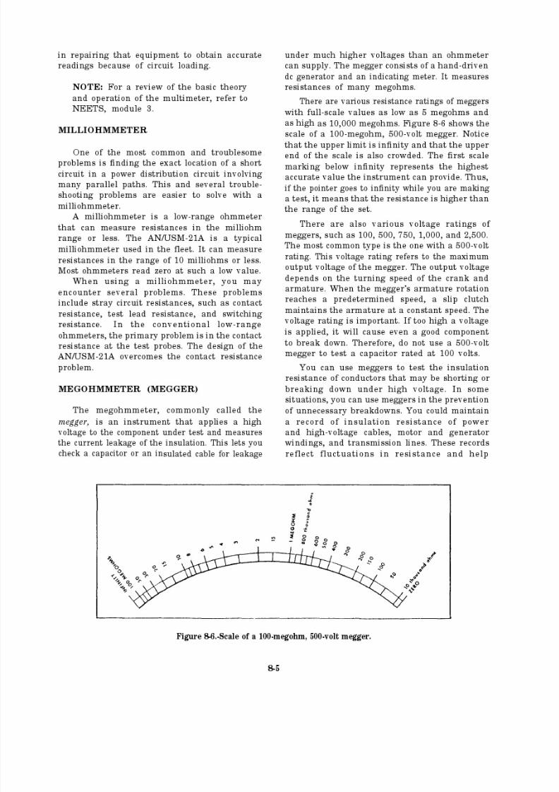
8/14/2019 US Navy Course NAVEDTRA 14028 - Aviation Electronics Technician-Basic
http://slidepdf.com/reader/full/us-navy-course-navedtra-14028-aviation-electronics-technician-basic 300/415
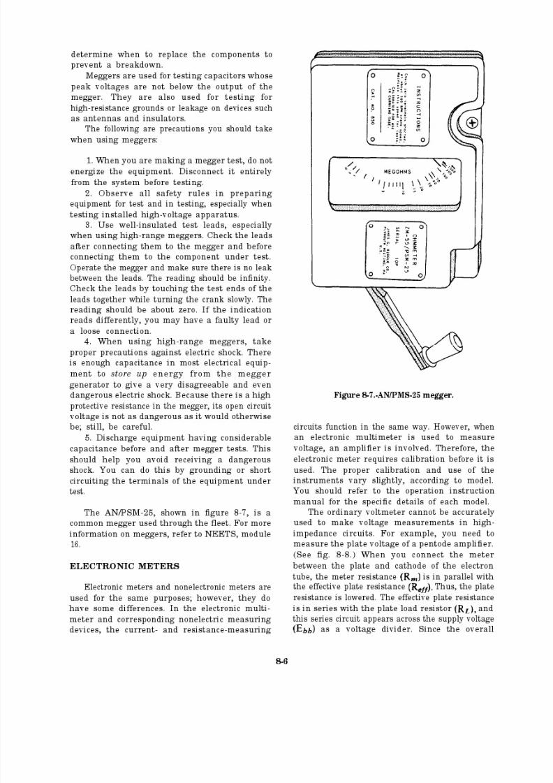
8/14/2019 US Navy Course NAVEDTRA 14028 - Aviation Electronics Technician-Basic
http://slidepdf.com/reader/full/us-navy-course-navedtra-14028-aviation-electronics-technician-basic 301/415
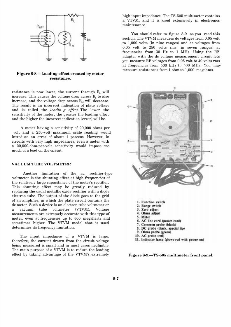
8/14/2019 US Navy Course NAVEDTRA 14028 - Aviation Electronics Technician-Basic
http://slidepdf.com/reader/full/us-navy-course-navedtra-14028-aviation-electronics-technician-basic 302/415
Figure 8-8.—Loading effect created by meter
resistance.
resistance is now lower, the current through RL
willincrease. This causes the voltage drop across R
Lto also
increase, and the voltage drop across Reff
will decrease.The result is an incorrect indication of plate voltageand is called the loadin g effect. The lower the
sensitivity of the meter, the greater the loading effectand the higher the incorrect indication (error) will be.
A meter having a sensitivity of 20,000 ohms per volt and a 250-volt maximum scale reading wouldintroduce an error of about 1 percent. However, in
circuits with very high impedances, even a meter witha 20,000-ohm-per-volt sensitivity would impose toomuch of a load on the circuit.
VACUUM TUBE VOLTMETER
Another limitation of the ac, rectifier-type voltmeter is the shunting effect at high frequencies of
the relatively large capacitance of the meter’s rectifier.This shunting effect may be greatly reduced byreplacing the usual metallic oxide rectifier with a diode
electron tube. The output of the diode goes to the gridof an amplifier, in which the plate circuit contains thedc meter. Such a device is an electron tube voltmeter or
a vacuum tube voltmeter (VTVM). Voltagemeasurements are extremely accurate with this type of meter, even at frequencies up to 500 megahertz andsometimes higher. The VTVM model that is used
determines its frequency limitation.
The input impedance of a VTVM is large;therefore, the current drawn from the circuit voltage
being measured is small and in most cases negligible.The main purpose of a VTVM is to reduce the loadingeffect by taking advantage of the VTVM’s extremely
high input impedance. The TS-505 multimeter containa VTVM, and it is used extensively in electroni
maintenance.
You should refer to figure 8-9 as you read thsection. The VTVM measures dc voltages from 0.05 voto 1,000 volts (in nine ranges) and ac voltages fro
0.05 volt to 250 volts rms (in seven ranges) frequencies from 30 Hz to 1 MHz. Using the R
adapter with the dc voltage measurement circuit leyou measure RF voltages from 0.05 volt to 40 volts rmat frequencies from 500 kHz to 500 MHz. You mmeasure resistances from 1 ohm to 1,000 megohms.
Figure 8-9.—TS-505 multimeter front panel.
8-7
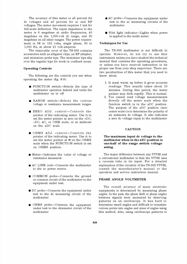
8/14/2019 US Navy Course NAVEDTRA 14028 - Aviation Electronics Technician-Basic
http://slidepdf.com/reader/full/us-navy-course-navedtra-14028-aviation-electronics-technician-basic 303/415
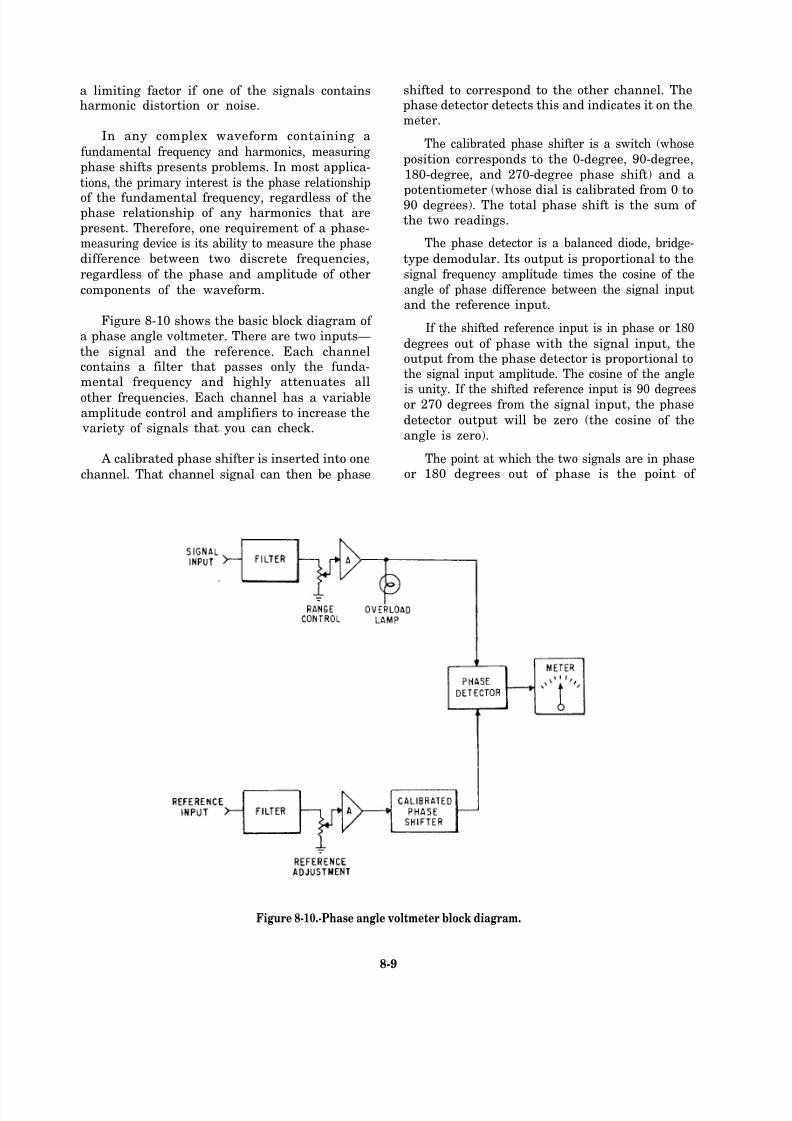
8/14/2019 US Navy Course NAVEDTRA 14028 - Aviation Electronics Technician-Basic
http://slidepdf.com/reader/full/us-navy-course-navedtra-14028-aviation-electronics-technician-basic 304/415
a limiting factor if one of the signals containsharmonic distortion or noise.
In any complex waveform containing a
fundamental frequency and harmonics, measuring
phase shifts presents problems. In most applica-
tions, the primary interest is the phase relationship
of the fundamental frequency, regardless of thephase relationship of any harmonics that are
present. Therefore, one requirement of a phase-measuring device is its ability to measure the phase
difference between two discrete frequencies,
regardless of the phase and amplitude of other
components of the waveform.
Figure 8-10 shows the basic block diagram of
a phase angle voltmeter. There are two inputs—
the signal and the reference. Each channelcontains a filter that passes only the funda-mental frequency and highly attenuates all
other frequencies. Each channel has a variableamplitude control and amplifiers to increase the
variety of signals that you can check.
A calibrated phase shifter is inserted into one
channel. That channel signal can then be phase
shifted to correspond to the other channel. Thephase detector detects this and indicates it on themeter.
The calibrated phase shifter is a switch (whose
position corresponds to the 0-degree, 90-degree,
180-degree, and 270-degree phase shift) and a
potentiometer (whose dial is calibrated from 0 to90 degrees). The total phase shift is the sum of the two readings.
The phase detector is a balanced diode, bridge-
type demodular. Its output is proportional to the
signal frequency amplitude times the cosine of the
angle of phase difference between the signal inputand the reference input.
If the shifted reference input is in phase or 180
degrees out of phase with the signal input, theoutput from the phase detector is proportional tothe signal input amplitude. The cosine of the angle
is unity. If the shifted reference input is 90 degreesor 270 degrees from the signal input, the phase
detector output will be zero (the cosine of the
angle is zero).
The point at which the two signals are in phaseor 180 degrees out of phase is the point of
Figure 8-10.-Phase angle voltmeter block diagram.
8-9
8/14/2019 US Navy Course NAVEDTRA 14028 - Aviation Electronics Technician-Basic
http://slidepdf.com/reader/full/us-navy-course-navedtra-14028-aviation-electronics-technician-basic 305/415
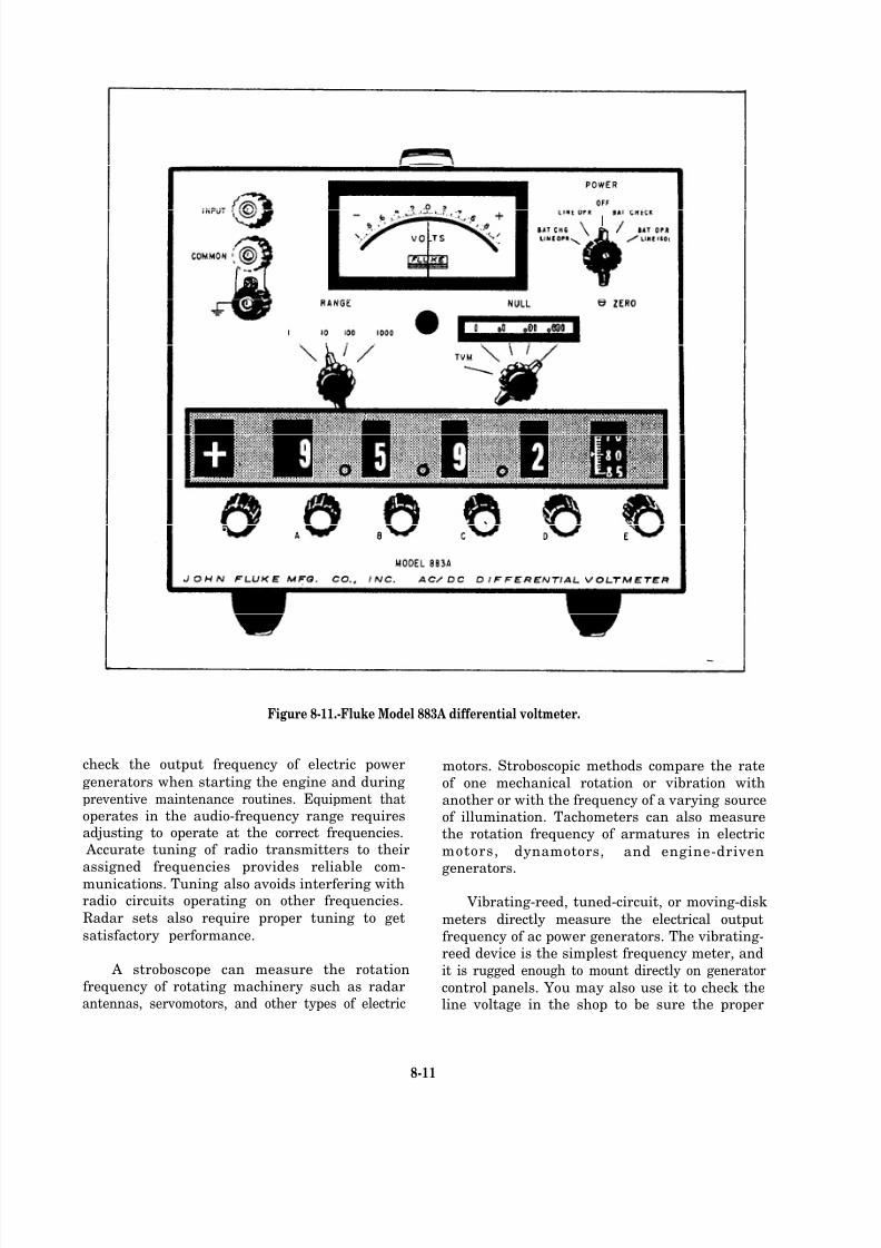
8/14/2019 US Navy Course NAVEDTRA 14028 - Aviation Electronics Technician-Basic
http://slidepdf.com/reader/full/us-navy-course-navedtra-14028-aviation-electronics-technician-basic 306/415
Figure 8-11.-Fluke Model 883A differential voltmeter.
check the output frequency of electric power
generators when starting the engine and during
preventive maintenance routines. Equipment thatoperates in the audio-frequency range requiresadjusting to operate at the correct frequencies.
Accurate tuning of radio transmitters to their
assigned frequencies provides reliable com-
munications. Tuning also avoids interfering withradio circuits operating on other frequencies.
Radar sets also require proper tuning to get
satisfactory performance.
A stroboscope can measure the rotation
frequency of rotating machinery such as radarantennas, servomotors, and other types of electric
motors. Stroboscopic methods compare the rate
of one mechanical rotation or vibration with
another or with the frequency of a varying sourceof illumination. Tachometers can also measurethe rotation frequency of armatures in electric
motors, dynamotors, and engine-driven
generators.
Vibrating-reed, tuned-circuit, or moving-disk
meters directly measure the electrical output
frequency of ac power generators. The vibrating-reed device is the simplest frequency meter, and
it is rugged enough to mount directly on generator
control panels. You may also use it to check theline voltage in the shop to be sure the proper
8-11
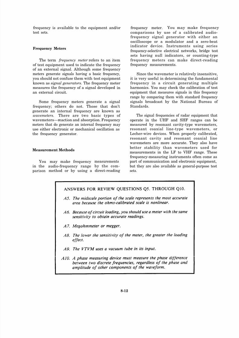
8/14/2019 US Navy Course NAVEDTRA 14028 - Aviation Electronics Technician-Basic
http://slidepdf.com/reader/full/us-navy-course-navedtra-14028-aviation-electronics-technician-basic 307/415
frequency is available to the equipment and/ortest sets.
Frequency Meters
The term frequency meter refers to an itemof test equipment used to indicate the frequencyof an external signal. Although some frequencymeters generate signals having a basic frequency,
you should not confuse them with test equipment
known as signal generators. The frequency metermeasures the frequency of a signal developed in
an external circuit.
Some frequency meters generate a signal
frequency; others do not. Those that don’t
generate an internal frequency are known aswavemeters. There are two basic types of wavemeters—reaction and absorption. Frequencymeters that do generate an internal frequency may
use either electronic or mechanical oscillation as
the frequency generator.
Measurement Methods
Youin the
parison
may make frequency
audio-frequency rangemethod or by using a
measurements
by the com-direct-reading
frequency meter. You may make frequency
comparisons by use of a calibrated audio-frequency signal generator with either an
oscilloscope or a modulator and a zero-beatindicator device. Instruments using series
frequency-selective electrical networks, bridge test
sets having null indicators, or counting-type
frequency meters can make direct-readingfrequency measurements.
Since the wavemeter is relatively insensitive,it is very useful in determining the fundamentalfrequency in a circuit generating multipleharmonics. You may check the calibration of test
equipment that measures signals in this frequency
range by comparing them with standard frequency
signals broadcast by the National Bureau of
Standards.
The signal frequencies of radar equipment that
operate in the UHF and SHF ranges can bemeasured by resonant cavity-type wavemeters,resonant coaxial line-type wavemeters, or
Lecher-wire devices. When properly calibrated,
resonant cavity and resonant coaxial linewavemeters are more accurate. They also have
better stability than wavemeters used for
measurements in the LF to VHF range. Thesefrequency-measuring instruments often come aspart of communication and electronic equipment,
but they are also available as general-purpose testsets.
8-12
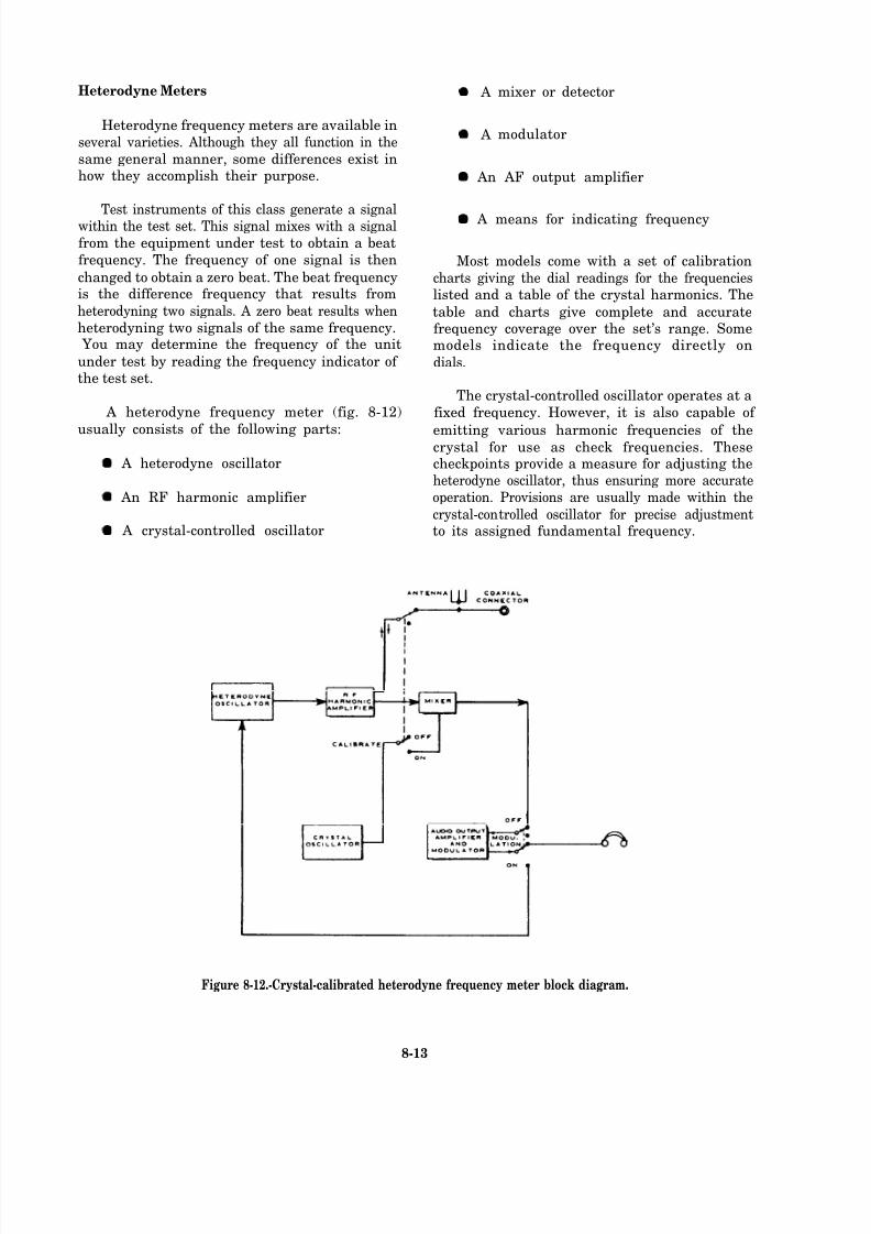
8/14/2019 US Navy Course NAVEDTRA 14028 - Aviation Electronics Technician-Basic
http://slidepdf.com/reader/full/us-navy-course-navedtra-14028-aviation-electronics-technician-basic 308/415
Heterodyne Meters
Heterodyne frequency meters are available in
several varieties. Although they all function in the
same general manner, some differences exist inhow they accomplish their purpose.
Test instruments of this class generate a signalwithin the test set. This signal mixes with a signal
from the equipment under test to obtain a beat
frequency. The frequency of one signal is then
changed to obtain a zero beat. The beat frequencyis the difference frequency that results from
heterodyning two signals. A zero beat results when
heterodyning two signals of the same frequency. You may determine the frequency of the unit
under test by reading the frequency indicator of the test set.
A heterodyne frequency meter (fig. 8-12)
usually consists of the following parts:
A heterodyne oscillator
An RF harmonic amplifier
A crystal-controlled oscillator
A
A
mixer or detector
modulator
An AF output amplifier
A means for indicating frequency
Most models come with a set of calibration
charts giving the dial readings for the frequencieslisted and a table of the crystal harmonics. The
table and charts give complete and accuratefrequency coverage over the set’s range. Somemodels indicate the frequency directly on
dials.
The crystal-controlled oscillator operates at a
fixed frequency. However, it is also capable of
emitting various harmonic frequencies of thecrystal for use as check frequencies. Thesecheckpoints provide a measure for adjusting theheterodyne oscillator, thus ensuring more accurate
operation. Provisions are usually made within the
crystal-controlled oscillator for precise adjustmentto its assigned fundamental frequency.
Figure 8-12.-Crystal-calibrated heterodyne frequency meter block diagram.
8-13
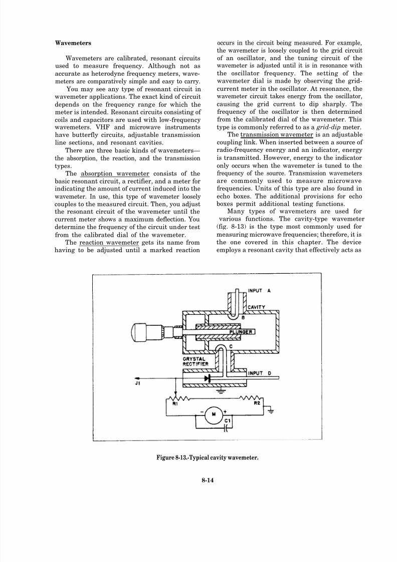
8/14/2019 US Navy Course NAVEDTRA 14028 - Aviation Electronics Technician-Basic
http://slidepdf.com/reader/full/us-navy-course-navedtra-14028-aviation-electronics-technician-basic 309/415
Wavemeters
Wavemeters are calibrated, resonant circuitsused to measure frequency. Although not as
accurate as heterodyne frequency meters, wave-
meters are comparatively simple and easy to carry.
You may see any type of resonant circuit in
wavemeter applications. The exact kind of circuitdepends on the frequency range for which themeter is intended. Resonant circuits consisting of
coils and capacitors are used with low-frequencywavemeters. VHF and microwave instruments
have butterfly circuits, adjustable transmission
line sections, and resonant cavities.
There are three basic kinds of wavemeters—
the absorption, the reaction, and the transmission
types.The absorption wavemeter consists of the
basic resonant circuit, a rectifier, and a meter forindicating the amount of current induced into the
wavemeter. In use, this type of wavemeter looselycouples to the measured circuit. Then, you adjustthe resonant circuit of the wavemeter until the
current meter shows a maximum deflection. You
determine the frequency of the circuit under test
from the calibrated dial of the wavemeter.The reaction wavemeter gets its name from
having to be adjusted until a marked reaction
occurs in the circuit being measured. For example,the wavemeter is loosely coupled to the grid circuit
of an oscillator, and the tuning circuit of thewavemeter is adjusted until it is in resonance with
the oscillator frequency. The setting of thewavemeter dial is made by observing the grid-
current meter in the oscillator. At resonance, the
wavemeter circuit takes energy from the oscillator,causing the grid current to dip sharply. Thefrequency of the oscillator is then determined
from the calibrated dial of the wavemeter. This
type is commonly referred to as a grid-dip meter.The transmission wavemeter is an adjustable
coupling link. When inserted between a source of radio-frequency energy and an indicator, energy
is transmitted. However, energy to the indicator
only occurs when the wavemeter is tuned to thefrequency of the source. Transmission wavemetersare commonly used to measure microwavefrequencies. Units of this type are also found in
echo boxes. The additional provisions for echoboxes permit additional testing functions.
Many types of wavemeters are used for various functions. The cavity-type wavemeter
(fig. 8-13) is the type most commonly used for
measuring microwave frequencies; therefore, it is
the one covered in this chapter. The device
employs a resonant cavity that effectively acts as
Figure 8-13.-Typical cavity wavemeter.
8-14
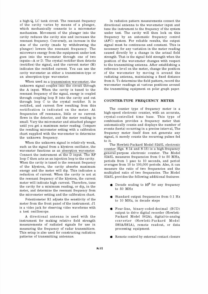
8/14/2019 US Navy Course NAVEDTRA 14028 - Aviation Electronics Technician-Basic
http://slidepdf.com/reader/full/us-navy-course-navedtra-14028-aviation-electronics-technician-basic 310/415
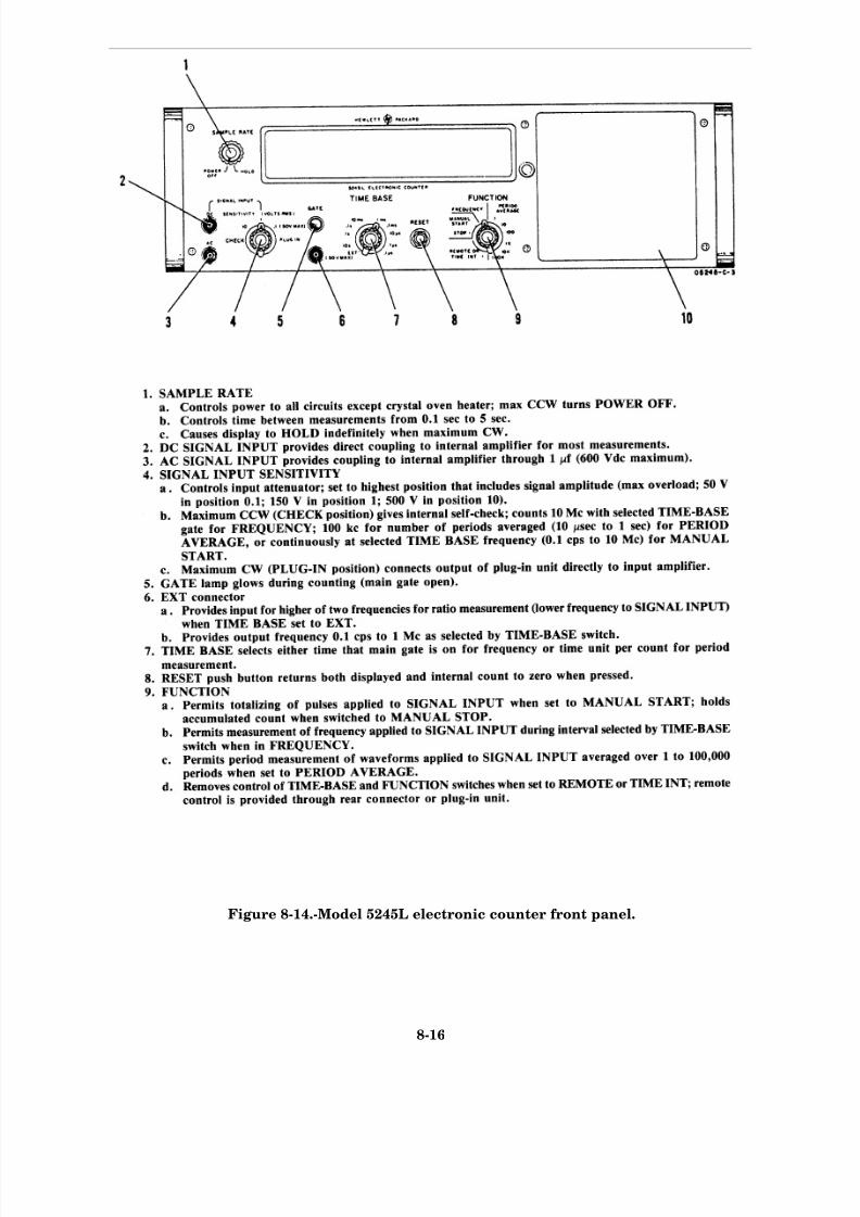
8/14/2019 US Navy Course NAVEDTRA 14028 - Aviation Electronics Technician-Basic
http://slidepdf.com/reader/full/us-navy-course-navedtra-14028-aviation-electronics-technician-basic 311/415
Figure 8-14.-Model 5245L electronic counter front panel.
8-16

8/14/2019 US Navy Course NAVEDTRA 14028 - Aviation Electronics Technician-Basic
http://slidepdf.com/reader/full/us-navy-course-navedtra-14028-aviation-electronics-technician-basic 312/415
Figure 8-15.—Model 5245L electronic counter rear panel.
8-17

8/14/2019 US Navy Course NAVEDTRA 14028 - Aviation Electronics Technician-Basic
http://slidepdf.com/reader/full/us-navy-course-navedtra-14028-aviation-electronics-technician-basic 313/415

8/14/2019 US Navy Course NAVEDTRA 14028 - Aviation Electronics Technician-Basic
http://slidepdf.com/reader/full/us-navy-course-navedtra-14028-aviation-electronics-technician-basic 314/415
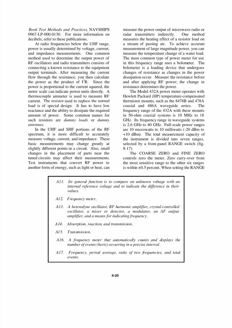
8/14/2019 US Navy Course NAVEDTRA 14028 - Aviation Electronics Technician-Basic
http://slidepdf.com/reader/full/us-navy-course-navedtra-14028-aviation-electronics-technician-basic 315/415
Book Test Methods and Practices, NAVSHIPS
0967-LP-000-0130. For more information on
decibels, refer to these publications.
At radio frequencies below the UHF range,
power is usually determined by voltage, current,
and impedance measurements. One common
method used to determine the output power of RF oscillators and radio transmitters consists of
connecting a known resistance to the equipment
output terminals. After measuring the current
flow through the resistance, you then calculate
the power as the product of I2R. Since the
power is proportional to the current squared, the
meter scale can indicate power units directly. A
thermocouple ammeter is used to measure RF
current. The resistor used to replace the normal
load is of special design. It has to have low
reactance and the ability to dissipate the required
amount of power. Some common names forsuch resistors are dummy loads or dummyantennas.
In the UHF and SHF portions of the RF
spectrum, it is more difficult to accurately
measure voltage, current, and impedance. These
basic measurements may change greatly at
slightly different points in a circuit. Also, small
changes in the placement of parts near the
tuned circuits may affect their measurements.
Test instruments that convert RF power to
another form of energy, such as light or heat, can
measure the power output of microwave radio or
radar transmitters indirectly. One method
measures the heating effect of a resistor load on
a stream of passing air. To achieve accurate
measurement of large magnitude power, you can
measure the temperature change of a water load.
The most common type of power meter for usein this frequency range uses a bolometer. The
bolometer is a loading device that undergoes
changes of resistance as changes in the power
dissipation occur. Measure the resistance before
and after applying RF power; the change in
resistance determines the power.
The Model 432A power meter operates with
Hewlett Packard (HP) temperature-compensated
thermistor mounts, such as the 8478B and 478A
coaxial and 486A waveguide series. The
frequency range of the 432A with these mounts
in 50-ohm coaxial systems is 10 MHz to 18GHz. Its frequency range in waveguide systems
is 2.6 GHz to 40 GHz. Full-scale power ranges
are 10 microwatts to 10 milliwatts (-20 dBm to
+10 dBm). The total measurement capacity of
the instrument is divided into seven ranges,
selected by a front-panel RANGE switch (fig.
8-17).
The COARSE ZERO and FINE ZERO
controls zero the meter. Zero carry-over from
the most sensitive range to the other six ranges
is within ±0.5 percent. When setting the RANGE
A11. Its general function is to compare an unknown voltage with aninternal reference voltage and to indicate the difference in their values.
A12. Frequency meter .
A13. A heterodyne oscillator, RF harmonic amplifier, crystal-controlled oscillator, a mixer or detector, a modulator, an AF output amplifier, and a means for indicating frequency.
A14. Absorption, reaction, and transmission.
A15. Transmission.
A16. A frequency meter that automatically counts and displays thenumber of events (hertz) occurring in a precise interval.
A17. Frequency, period average, ratio of two frequencies, and totalevents.
8-20
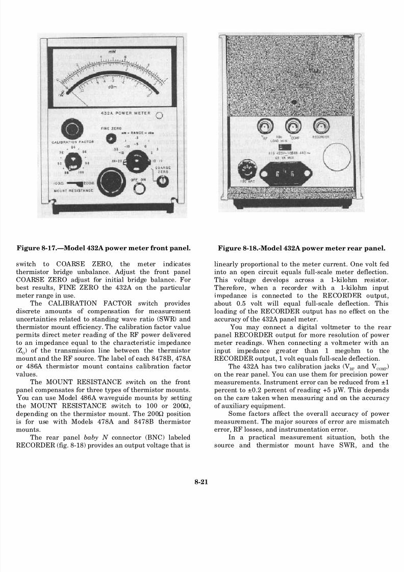
8/14/2019 US Navy Course NAVEDTRA 14028 - Aviation Electronics Technician-Basic
http://slidepdf.com/reader/full/us-navy-course-navedtra-14028-aviation-electronics-technician-basic 316/415
8-21
Figure 8-17.—Model 432A power meter front panel.
switch to COARSE ZERO, the meter indicates
thermistor bridge unbalance. Adjust the front panelCOARSE ZERO adjust for initial bridge balance. Forbest results, FINE ZERO the 432A on the particular
meter range in use.
The CALIBRATION FACTOR switch providesdiscrete amounts of compensation for measurement
uncertainties related to standing wave ratio (SWR) andthermistor mount efficiency. The calibration factor valuepermits direct meter reading of the RF power delivered
to an impedance equal to the characteristic impedance(Z
O) of the transmission line between the thermistor
mount and the RF source. The label of each 8478B, 478Aor 486A thermistor mount contains calibration factor
values.The MOUNT RESISTANCE switch on the front
panel compensates for three types of thermistor mounts.
You can use Model 486A waveguide mounts by settingthe MOUNT RESISTANCE switch to 100 or 200Ω,
depending on the thermistor mount. The 200Ω positionis for use with Models 478A and 8478B thermistor
mounts.The rear panel baby N connector (BNC) labeled
RECORDER (fig. 8-18) provides an output voltage that is
Figure 8-18.-Model 432A power meter rear pan
linearly proportional to the meter current. One volt into an open circuit equals full-scale meter deflect
This voltage develops across a 1-kilohm resisTherefore, when a recorder with a 1-kilohm inimpedance is connected to the RECORDER outp
about 0.5 volt will equal full-scale deflection. Tloading of the RECORDER output has no effect onaccuracy of the 432A panel meter.
You may connect a digital voltmeter to thepanel RECORDER output for more resolution of pometer readings. When connecting a voltmeter with
input impedance greater than 1 megohm toRECORDER output, 1 volt equals full-scale deflection
The 432A has two calibration jacks (VRF and VC
on the rear panel. You can use them for precision pow
measurements. Instrument error can be reduced frompercent to ±0.2 percent of reading +5 µW. This depe
on the care taken when measuring and on the accurof auxiliary equipment.Some factors affect the overall accuracy of po
measurement. The major sources of error are mismaerror, RF losses, and instrumentation error.
In a practical measurement situation, both
source and thermistor mount have SWR, and
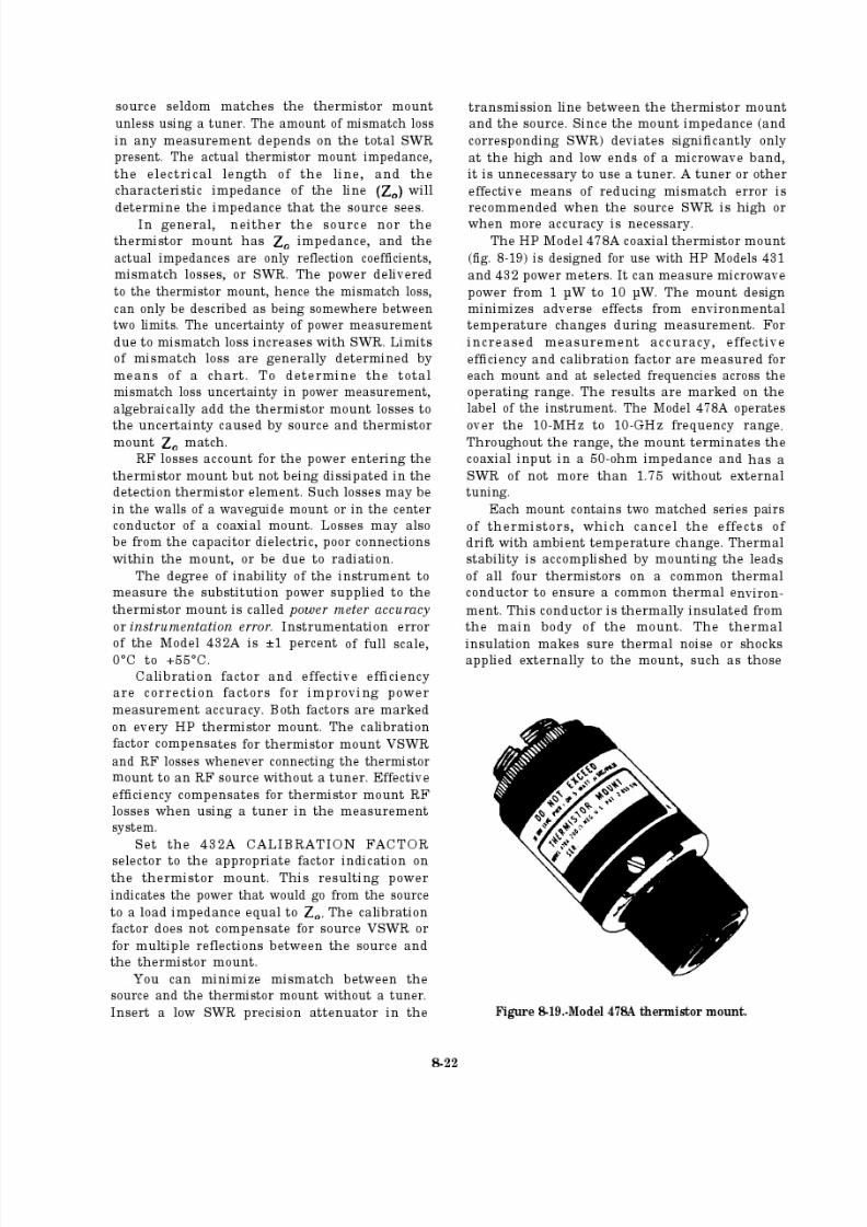
8/14/2019 US Navy Course NAVEDTRA 14028 - Aviation Electronics Technician-Basic
http://slidepdf.com/reader/full/us-navy-course-navedtra-14028-aviation-electronics-technician-basic 317/415
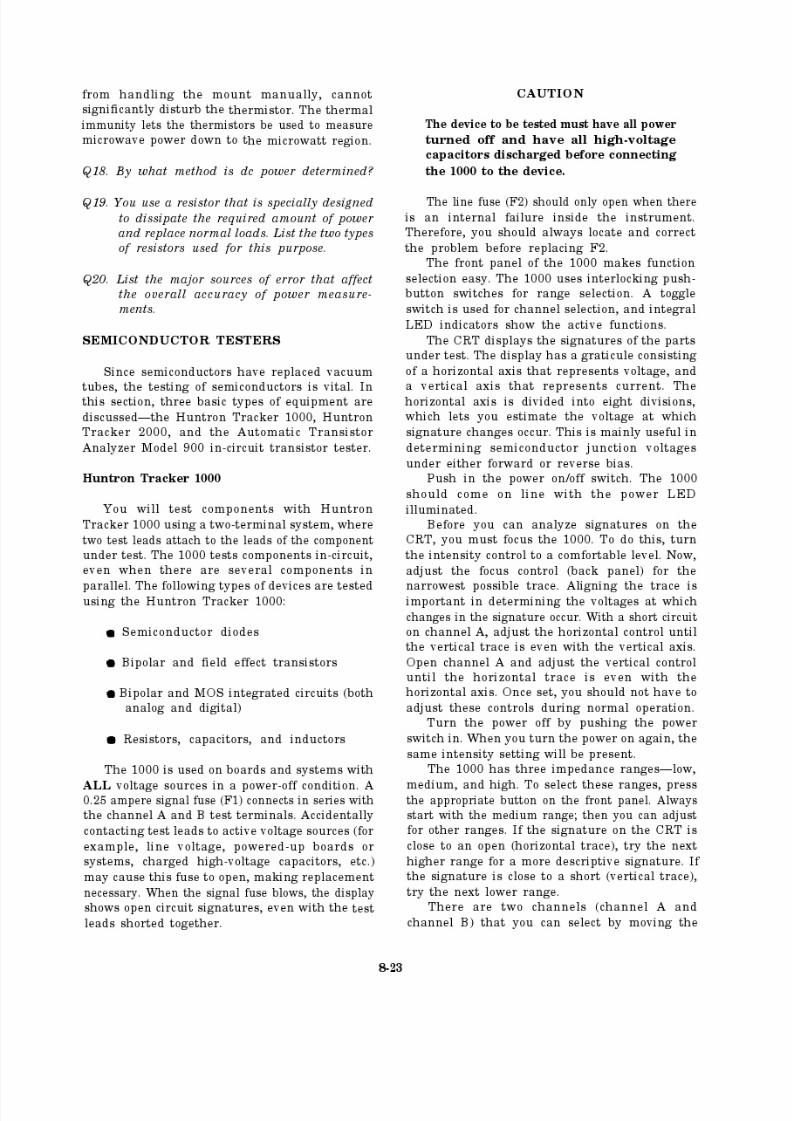
8/14/2019 US Navy Course NAVEDTRA 14028 - Aviation Electronics Technician-Basic
http://slidepdf.com/reader/full/us-navy-course-navedtra-14028-aviation-electronics-technician-basic 318/415
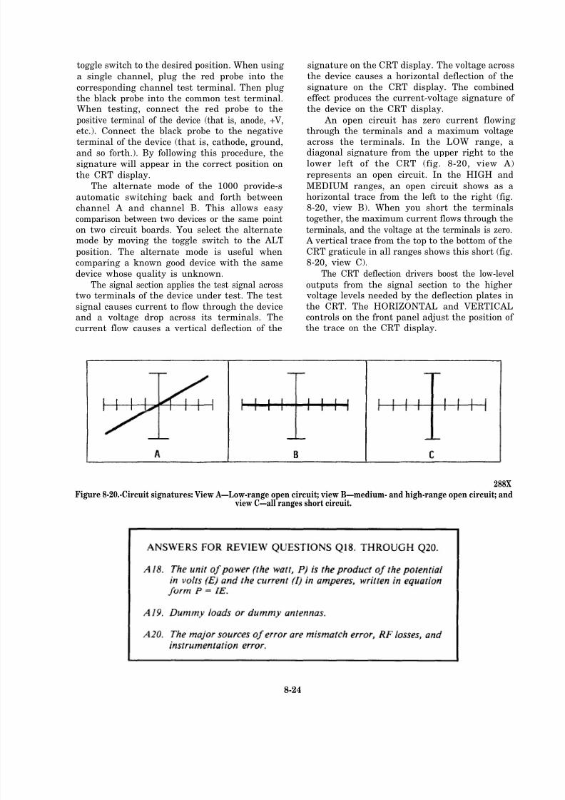
8/14/2019 US Navy Course NAVEDTRA 14028 - Aviation Electronics Technician-Basic
http://slidepdf.com/reader/full/us-navy-course-navedtra-14028-aviation-electronics-technician-basic 319/415
toggle switch to the desired position. When using
a single channel, plug the red probe into the
corresponding channel test terminal. Then plugthe black probe into the common test terminal.When testing, connect the red probe to the
positive terminal of the device (that is, anode, +V,etc.). Connect the black probe to the negative
terminal of the device (that is, cathode, ground,and so forth.). By following this procedure, the
signature will appear in the correct position on
the CRT display.
The alternate mode of the 1000 provide-s
automatic switching back and forth betweenchannel A and channel B. This allows easy
comparison between two devices or the same pointon two circuit boards. You select the alternatemode by moving the toggle switch to the ALT
position. The alternate mode is useful when
comparing a known good device with the same
device whose quality is unknown.
The signal section applies the test signal acrosstwo terminals of the device under test. The test
signal causes current to flow through the deviceand a voltage drop across its terminals. Thecurrent flow causes a vertical deflection of the
signature on the CRT display. The voltage across
the device causes a horizontal deflection of the
signature on the CRT display. The combinedeffect produces the current-voltage signature of
the device on the CRT display.
An open circuit has zero current flowingthrough the terminals and a maximum voltage
across the terminals. In the LOW range, adiagonal signature from the upper right to the
lower left of the CRT (fig. 8-20, view A)
represents an open circuit. In the HIGH and
MEDIUM ranges, an open circuit shows as ahorizontal trace from the left to the right (fig.8-20, view B). When you short the terminals
together, the maximum current flows through the
terminals, and the voltage at the terminals is zero. A vertical trace from the top to the bottom of the
CRT graticule in all ranges shows this short (fig.8-20, view C).
The CRT deflection drivers boost the low-level
outputs from the signal section to the higher voltage levels needed by the deflection plates in
the CRT. The HORIZONTAL and VERTICALcontrols on the front panel adjust the position of the trace on the CRT display.
288XFigure 8-20.-Circuit signatures: View A—Low-range open circuit; view B—medium- and high-range open circuit; and
view C—all ranges short circuit.
8-24
8/14/2019 US Navy Course NAVEDTRA 14028 - Aviation Electronics Technician-Basic
http://slidepdf.com/reader/full/us-navy-course-navedtra-14028-aviation-electronics-technician-basic 320/415
You use three other CRT controls to adjust
the brightness and clarity of the trace—INTENSITY, FOCUS, and ASTIGMATISM.
The front panel intensity control is the primary
means of adjusting the visual characteristics of
the trace. The focus control is on the back paneland is operator adjustable. The astigmatism trim
pot is inside the 1000 on the main printed circuitboard. The pot is factory adjusted to the correct
setting.
Huntron Tracker 2000
The Huntron Tracker 2000 (fig. 8-21) is a versatile troubleshooting tool having the following
features:
Multiple test signal frequencies (50/60 Hz,
400 Hz, 2000 Hz)
Four impedance ranges (low, medium 1,medium 2, high)
Automatic range scanning
Range control: high lockout
Adjustable rate of channel
and/or range scanning
alteration
Dual polarity pulse generator for dynamic
testing of three terminal devices
LED indicators for all functions
Dual channel capability for easy
comparison
Large CRT display with easy to operatecontrols
GENERAL OPERATION.— You will test
components using the 2000 t wo-terminal system.It also has a three-terminal system when using thebuilt-in pulse generator. When using this system,
you place two test leads on the leads of the
component under test. The 2000 tests componentsin-circuit, even when there are several parts in
parallel.Use the 2000 only on boards and systems with
all voltage sources in a power-off condition. A
0.25 ampere signal fuse connects in series with thechannels A and B test terminals. Accidentalcontact of the test leads to active voltage sources,
such as line voltage, powered-up boards or
systems, and charged high-voltage capacitors maycause this fuse to open, making replacementnecessary. When the signal fuse blows, the 2000
displays short circuit signatures even with the test
leads open.
CAUTION
The device under test must have all power
turned off and all high-voltage capacitors
discharged before connecting the 2000 to
the device.
288X
Figure 8-21.-Huntron Tracker 2000.
8-25
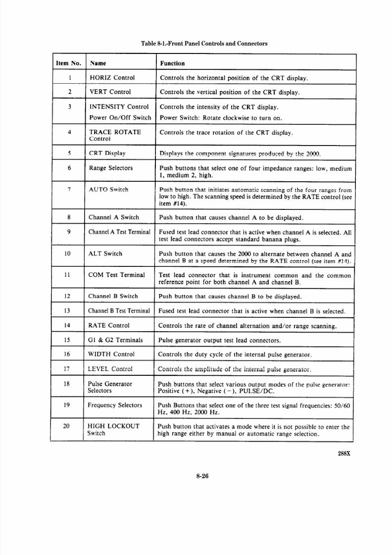
8/14/2019 US Navy Course NAVEDTRA 14028 - Aviation Electronics Technician-Basic
http://slidepdf.com/reader/full/us-navy-course-navedtra-14028-aviation-electronics-technician-basic 321/415
Table 8-1.-Front Panel Controls and Connectors
288X
8-26
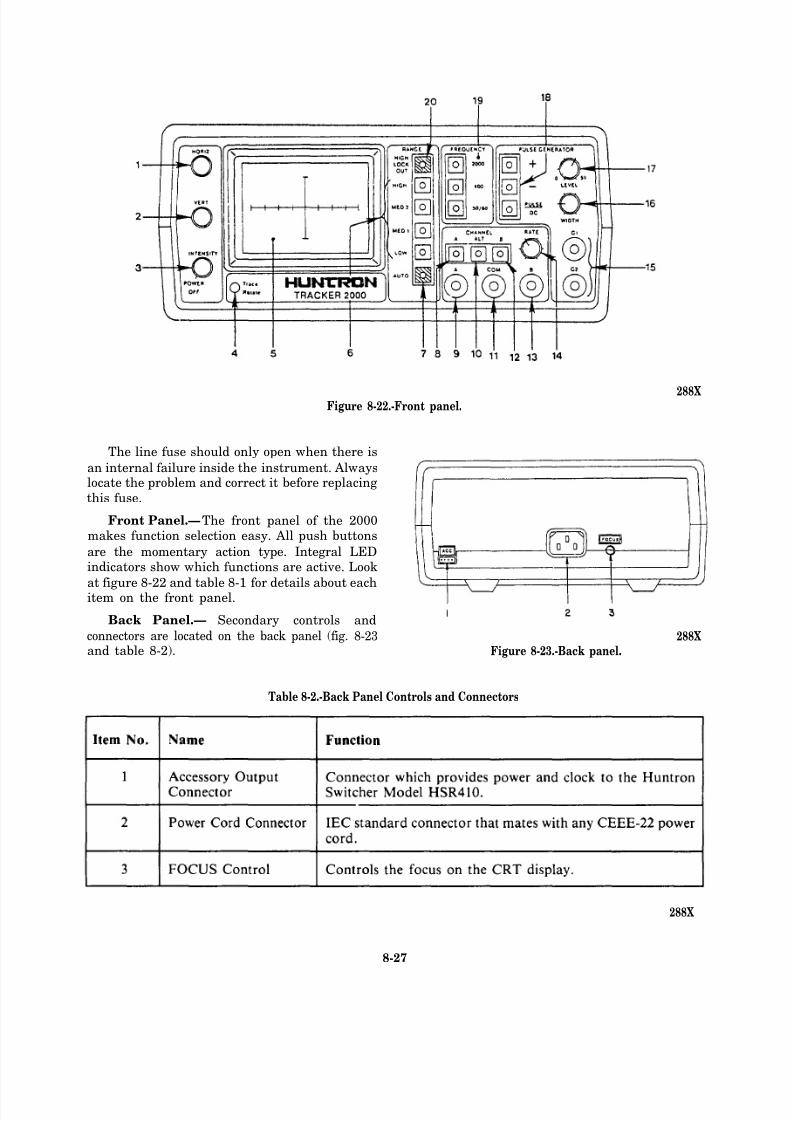
8/14/2019 US Navy Course NAVEDTRA 14028 - Aviation Electronics Technician-Basic
http://slidepdf.com/reader/full/us-navy-course-navedtra-14028-aviation-electronics-technician-basic 322/415
Figure 8-22.-Front panel.288X
The line fuse should only open when there is
an internal failure inside the instrument. Alwayslocate the problem and correct it before replacing
this fuse.
Front Panel.—The front panel of the 2000makes function selection easy. All push buttons
are the momentary action type. Integral LEDindicators show which functions are active. Look
at figure 8-22 and table 8-1 for details about eachitem on the front panel.
Back Panel.— Secondary controls and
connectors are located on the back panel (fig. 8-23and table 8-2). Figure 8-23.-Back panel.
Table 8-2.-Back Panel Controls and Connectors
288X
288X
8-27
8/14/2019 US Navy Course NAVEDTRA 14028 - Aviation Electronics Technician-Basic
http://slidepdf.com/reader/full/us-navy-course-navedtra-14028-aviation-electronics-technician-basic 323/415

8/14/2019 US Navy Course NAVEDTRA 14028 - Aviation Electronics Technician-Basic
http://slidepdf.com/reader/full/us-navy-course-navedtra-14028-aviation-electronics-technician-basic 324/415
8/14/2019 US Navy Course NAVEDTRA 14028 - Aviation Electronics Technician-Basic
http://slidepdf.com/reader/full/us-navy-course-navedtra-14028-aviation-electronics-technician-basic 325/415

8/14/2019 US Navy Course NAVEDTRA 14028 - Aviation Electronics Technician-Basic
http://slidepdf.com/reader/full/us-navy-course-navedtra-14028-aviation-electronics-technician-basic 326/415
8/14/2019 US Navy Course NAVEDTRA 14028 - Aviation Electronics Technician-Basic
http://slidepdf.com/reader/full/us-navy-course-navedtra-14028-aviation-electronics-technician-basic 327/415
8/14/2019 US Navy Course NAVEDTRA 14028 - Aviation Electronics Technician-Basic
http://slidepdf.com/reader/full/us-navy-course-navedtra-14028-aviation-electronics-technician-basic 328/415

8/14/2019 US Navy Course NAVEDTRA 14028 - Aviation Electronics Technician-Basic
http://slidepdf.com/reader/full/us-navy-course-navedtra-14028-aviation-electronics-technician-basic 329/415
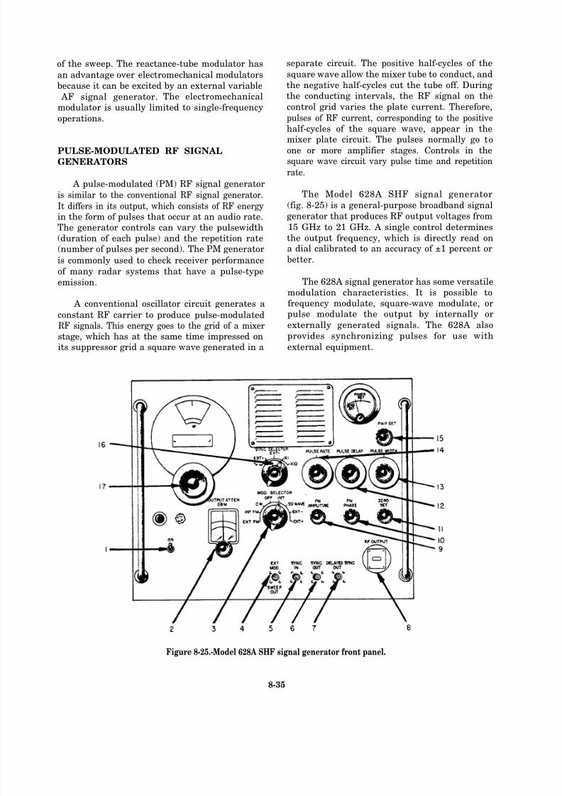
8/14/2019 US Navy Course NAVEDTRA 14028 - Aviation Electronics Technician-Basic
http://slidepdf.com/reader/full/us-navy-course-navedtra-14028-aviation-electronics-technician-basic 330/415
of the sweep. The reactance-tube modulator has
an advantage over electromechanical modulators
because it can be excited by an external variable
AF signal generator. The electromechanical
modulator is usually limited to single-frequency
operations.
PULSE-MODULATED RF SIGNAL
GENERATORS
A pulse-modulated (PM) RF signal generator
is similar to the conventional RF signal generator.
It differs in its output, which consists of RF energyin the form of pulses that occur at an audio rate.The generator controls can vary the pulsewidth(duration of each pulse) and the repetition rate(number of pulses per second). The PM generator
is commonly used to check receiver performance
of many radar systems that have a pulse-type
emission.
A conventional oscillator circuit generates a
constant RF carrier to produce pulse-modulatedRF signals. This energy goes to the grid of a mixerstage, which has at the same time impressed onits suppressor grid a square wave generated in a
separate circuit. The positive half-cycles of the
square wave allow the mixer tube to conduct, and
the negative half-cycles cut the tube off. Duringthe conducting intervals, the RF signal on the
control grid varies the plate current. Therefore,
pulses of RF current, corresponding to the positivehalf-cycles of the square wave, appear in the
mixer plate circuit. The pulses normally go toone or more amplifier stages. Controls in thesquare wave circuit vary pulse time and repetition
rate.
The Model 628A SHF signal generator
(fig. 8-25) is a general-purpose broadband signal
generator that produces RF output voltages from
15 GHz to 21 GHz. A single control determines
the output frequency, which is directly read ona dial calibrated to an accuracy of ±1 percent or
better.
The 628A signal generator has some versatilemodulation characteristics. It is possible tofrequency modulate, square-wave modulate, orpulse modulate the output by internally or
externally generated signals. The 628A also
provides synchronizing pulses for use with
external equipment.
Figure 8-25.-Model 628A SHF signal generator front panel.
8-35
8/14/2019 US Navy Course NAVEDTRA 14028 - Aviation Electronics Technician-Basic
http://slidepdf.com/reader/full/us-navy-course-navedtra-14028-aviation-electronics-technician-basic 331/415
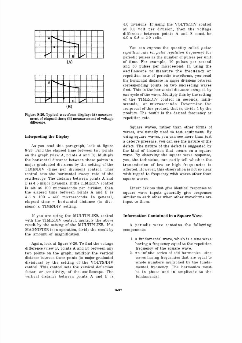
8/14/2019 US Navy Course NAVEDTRA 14028 - Aviation Electronics Technician-Basic
http://slidepdf.com/reader/full/us-navy-course-navedtra-14028-aviation-electronics-technician-basic 332/415
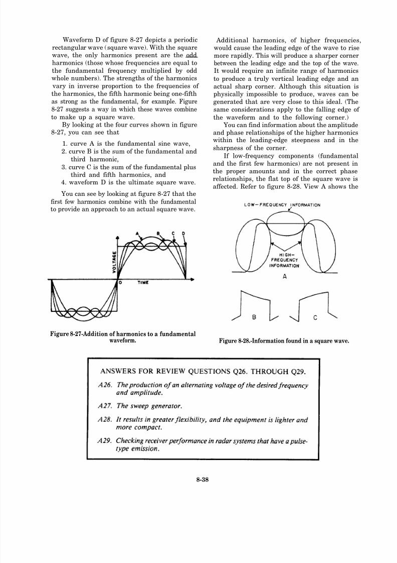
8/14/2019 US Navy Course NAVEDTRA 14028 - Aviation Electronics Technician-Basic
http://slidepdf.com/reader/full/us-navy-course-navedtra-14028-aviation-electronics-technician-basic 333/415
Waveform D of figure 8-27 depicts a periodic
rectangular wave (square wave). With the squarewave, the only harmonics present are the odd
harmonics (those whose frequencies are equal to
the fundamental frequency multiplied by oddwhole numbers). The strengths of the harmonics
vary in inverse proportion to the frequencies of
the harmonics, the fifth harmonic being one-fifth
as strong as the fundamental, for example. Figure
8-27 suggests a way in which these waves combine
to make up a square wave.By looking at the four curves shown in figure
8-27, you can see that
1. curve A is the fundamental sine wave,
2. curve B is the sum of the fundamental and
third harmonic,
3. curve C is the sum of the fundamental plusthird and fifth harmonics, and
4. waveform D is the ultimate square wave.
You can see by looking at figure 8-27 that the
first few harmonics combine with the fundamentalto provide an approach to an actual square wave.
Figure 8-27-Addition of harmonics to a fundamentalwaveform.
Additional harmonics, of higher frequencies,would cause the leading edge of the wave to rise
more rapidly. This will produce a sharper cornerbetween the leading edge and the top of the wave.It would require an infinite range of harmonics
to produce a truly vertical leading edge and an
actual sharp corner. Although this situation isphysically impossible to produce, waves can be
generated that are very close to this ideal. (The
same considerations apply to the falling edge of
the waveform and to the following corner.) You can find information about the amplitude
and phase relationships of the higher harmonicswithin the leading-edge steepness and in the
sharpness of the corner.
If low-frequency components (fundamental
and the first few harmonics) are not present inthe proper amounts and in the correct phaserelationships, the flat top of the square wave is
affected. Refer to figure 8-28. View A shows the
Figure 8-28.-Information found in a square wave.
8-38
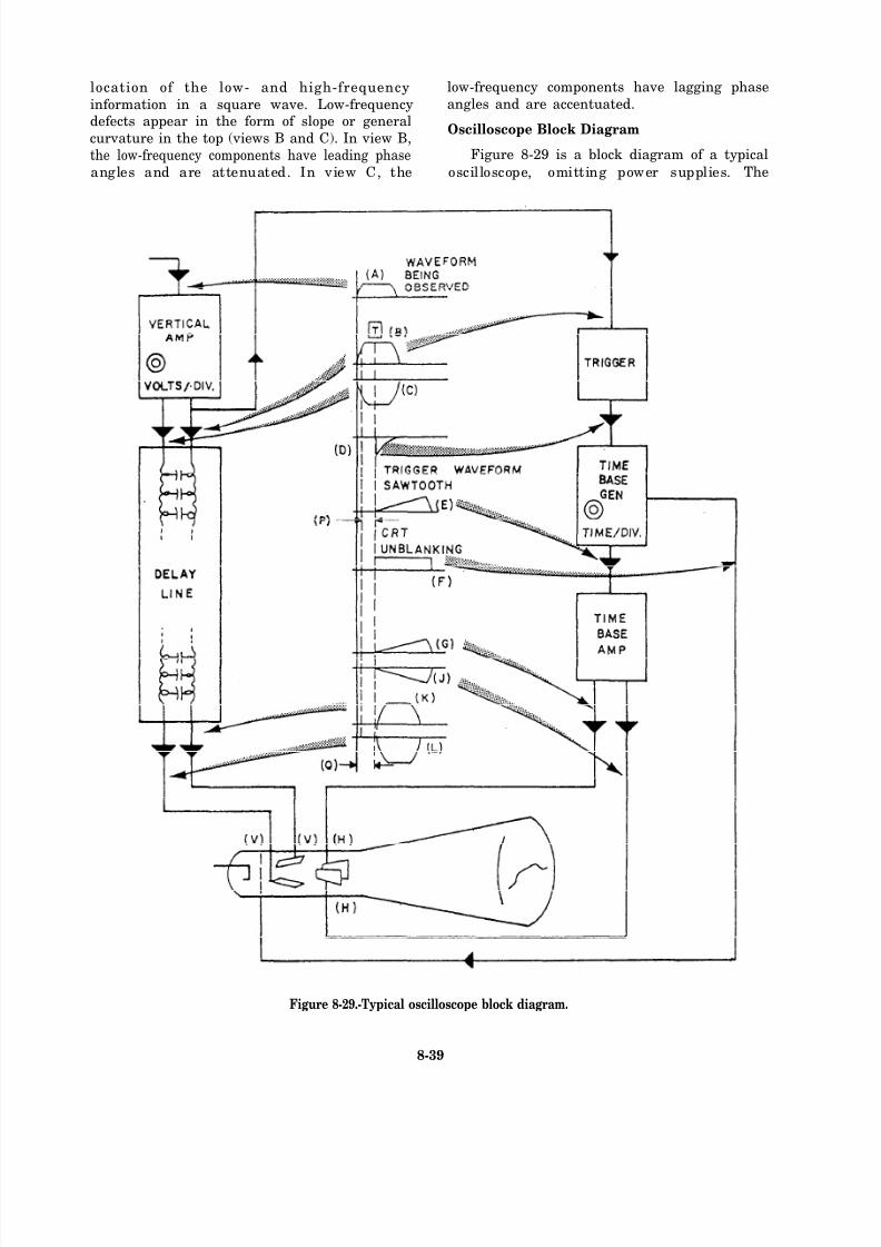
8/14/2019 US Navy Course NAVEDTRA 14028 - Aviation Electronics Technician-Basic
http://slidepdf.com/reader/full/us-navy-course-navedtra-14028-aviation-electronics-technician-basic 334/415
location of the low- and high-frequency low-frequency components have lagging phase
information in a square wave. Low-frequency angles and are accentuated.
defects appear in the form of slope or general
curvature in the top (views B and C). In view B,Oscilloscope Block Diagram
the low-frequency components have leading phase Figure 8-29 is a block diagram of a typical
angles and are attenuated. In view C, the oscilloscope, omitting power supplies. The
Figure 8-29.-Typical oscilloscope block diagram.
8-39
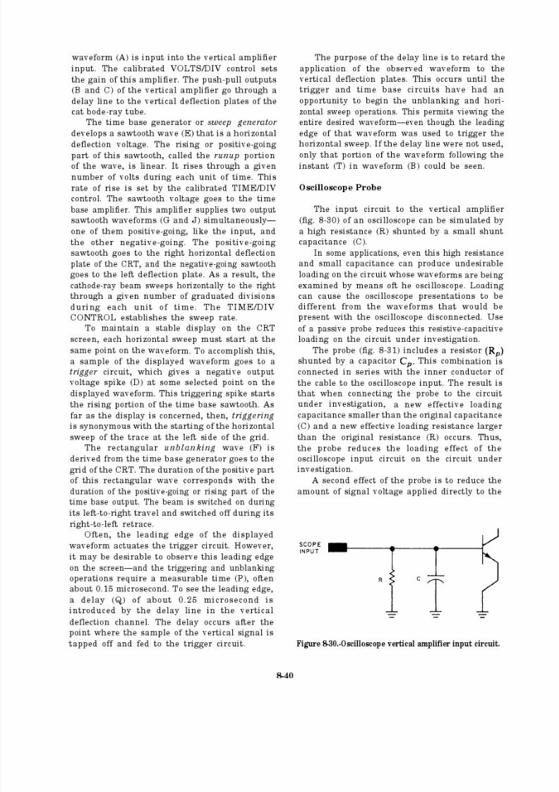
8/14/2019 US Navy Course NAVEDTRA 14028 - Aviation Electronics Technician-Basic
http://slidepdf.com/reader/full/us-navy-course-navedtra-14028-aviation-electronics-technician-basic 335/415

8/14/2019 US Navy Course NAVEDTRA 14028 - Aviation Electronics Technician-Basic
http://slidepdf.com/reader/full/us-navy-course-navedtra-14028-aviation-electronics-technician-basic 336/415
Figure 8-31.-Oscilloscope vertical amplifier using a passive probe input.
oscilloscope input connection for a given amount
of original signal voltage. This occurs because of the voltage-divider action of and R. This effectis taken into account in the attenuation ratio
marked on the probe. Thus, if the probe is a10 x ATTEN, all oscilloscope voltage indications
must be multiplied by 10.
If an oscilloscope equipped with a probe isused to look at a square wave, and the probecapacitor is too small, some of the high-frequency components of the square wave are
bypassed around the oscilloscope input terminalsby the input capacitance (C). Thus, the steepness
of the leading edge of the displayed square wave(fig. 8-32, view A) is reduced.
If the probe capacitor is adjusted to the correct value, a compensating amount of high-frequency
information is bypassed around the probe resistor
Figure 8-32 .-Effects of probe adjustment.
(fig. 8-31). To makeup for the loss through
C (fig. 8-31), the leading edge of the displayedsquare wave is restored to its original steepness(fig. 8-32, view B). If (fig. 8-31) is made toolarge, the high-frequency response of the circuit
is overcompensated and applies too much high-
frequency information to the oscilloscope input
connection. This results in an overshoot in thedisplayed waveform (fig. 8-32, view C) that wasnot present in the original waveform. (fig.
8-31) is adjusted to its correct value by using theprobe to display the square wave generated by the
voltage calibrator, which is a part of theoscilloscope. Adjustment is made to display a
square wave with as flat a top as possible.
You must check the probe adjustmentwhenever you use a probe with an oscilloscope
or a plug-in preamplifier. This is especiallyimportant if the previous use was with an input
capacitance different from that of the instrumentto which you are now connecting the probe.
NOTE: As indicated in figure 8-31, the
attenuation achieved is a result of R as well
as Though you may swap probes with
other types of oscilloscopes, the calibrationmay be in error even though the waveform
distortion may adjust out.
8-41
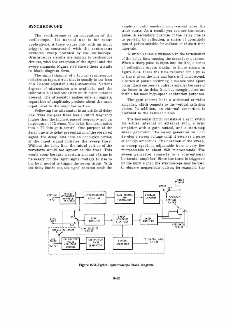
8/14/2019 US Navy Course NAVEDTRA 14028 - Aviation Electronics Technician-Basic
http://slidepdf.com/reader/full/us-navy-course-navedtra-14028-aviation-electronics-technician-basic 337/415
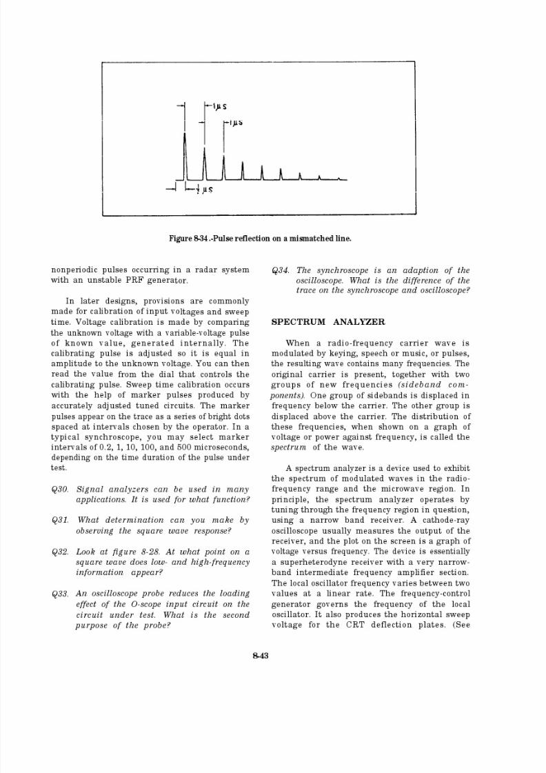
8/14/2019 US Navy Course NAVEDTRA 14028 - Aviation Electronics Technician-Basic
http://slidepdf.com/reader/full/us-navy-course-navedtra-14028-aviation-electronics-technician-basic 338/415
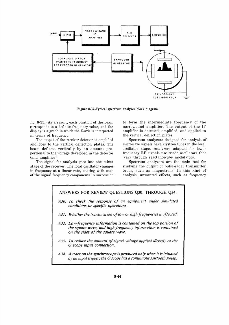
8/14/2019 US Navy Course NAVEDTRA 14028 - Aviation Electronics Technician-Basic
http://slidepdf.com/reader/full/us-navy-course-navedtra-14028-aviation-electronics-technician-basic 339/415
Figure 8-35.-Typical spectrum analyzer block diagram.
fig. 8-35.) As a result, each position of the beam
corresponds to a definite frequency value, and thedisplay is a graph in which the X-axis is interpretedin terms of frequency.
The output of the receiver detector is amplified
and goes to the vertical deflection plates. The
beam deflects vertically by an amount pro-
portional to the voltage de veloped in the detector(and amplifier).
The signal for analysis goes into the mixer
stage of the receiver. The local oscillator changes
in frequency at a linear rate, beating with eachof the signal frequency components in succession
to form the intermediate frequency of thenarrowband amplifier. The output of the IFamplifier is detected, amplified, and applied tothe vertical deflection plates.
Spectrum analyzers designed for analysis of
microwave signals have klystron tubes in the localoscillator stage. Analyzers adapted for lower
frequency RF signals use triode oscillators that vary through reactance-tube modulators.
Spectrum analyzers are the main tool for
studying the output of pulse-radar transmitter
tubes, such as magnetrons. In this kind of analysis, unwanted effects, such as frequency
8-44

8/14/2019 US Navy Course NAVEDTRA 14028 - Aviation Electronics Technician-Basic
http://slidepdf.com/reader/full/us-navy-course-navedtra-14028-aviation-electronics-technician-basic 340/415
Figure 8-36.-Frequency spectra.
modulation of the carrier, are easy to detect. In
pure amplitude modulation of a carrier wave by
a square pulse, the spectrum is symmetrical aboutthe carrier frequency. Lack of symmetry indicates
the presence of frequency modulation. Look at view A of figure 8-36. It shows a spectrum
representing the ideal condition. Views B and C
show examples of undesirable magnetron spectra.These forms indicate trouble in the modulator,
the tuning system, or in the magnetron tube itself.The best definition of carrier frequency is the
center frequency in a symmetrical spectrum (fig.
8-36, view A). Some analyzers use this principle
as a means of carrier frequency measurement. A
sharply resonant circuit in the receiver acts as a
trap to prevent an extremely narrow range of
frequencies from appearing in the output of theIF amplifier. The result of its use is a gap thatappears in the display, and the gap correspondsto the resonant frequency of the trap. The
adjustment of the trap is calibrated in frequency,and the circuit can be adjusted to make the gap
occur in the center of the spectrum. You can thenread the frequency of the carrier from the
calibration of the trap.For more information about spectrum
analyzers, refer to NEETS, module 16. In
addition, the EIMB Test M ethods and Practices,
NAVSHIPS 0967-LP-000-0130, contains detailed
discussions of spectrum analysis techniques.
Echo BOX
The echo box is for use in field testing,
troubleshooting, and adjusting pulsed-type radar
systems. Although simple in construction andoperation, it has many applications. If properlyused within its design limitations, the echo box
can frequently eliminate the need for a complex
test setup and an elaborate step-by-step testingprocedure. The echo box uses passive circuitry,which does not require any external power other
than the radar set whose signal is under analysis.
External power requirement is a critical factorwith most other test sets.
The echo box is similar in operation to a tuned
cavity frequency meter; however, it has different
capabilities. The tuned cavity frequency meter can
measure the frequency of CW or pulsed RF
signals in the microwave range. The echo box,however, has no practical application in the testing
or analysis of CW equipment signals. Figure 8-37indicates the basic functional elements of a typical
echo box.
Energy from the radar transmitter goesthrough the directional couplers to the resonant
Figure 8-37.-Typical echo box functional circuit.
8-45
8/14/2019 US Navy Course NAVEDTRA 14028 - Aviation Electronics Technician-Basic
http://slidepdf.com/reader/full/us-navy-course-navedtra-14028-aviation-electronics-technician-basic 341/415
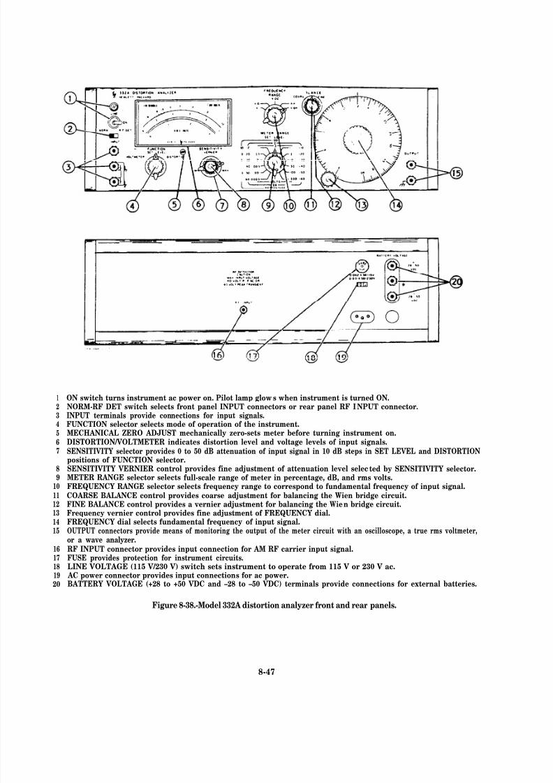
8/14/2019 US Navy Course NAVEDTRA 14028 - Aviation Electronics Technician-Basic
http://slidepdf.com/reader/full/us-navy-course-navedtra-14028-aviation-electronics-technician-basic 342/415
1
2
345
67
89
101112131415
1617181920
ON switch turns instrument ac power on. Pilot lamp glows when instrument is turned ON.NORM-RF DET switch selects front panel INPUT connectors or rear panel RF INPUT connector.INPUT terminals provide connections for input signals.FUNCTION selector selects mode of operation of the instrument.MECHANICAL ZERO ADJUST mechanically zero-sets meter before turning instrument on.DISTORTION/VOLTMETER indicates distortion level and voltage levels of input signals.SENSITIVITY selector provides 0 to 50 dB attenuation of input signal in 10 dB steps in SET LEVEL and DISTORTIONpositions of FUNCTION selector.SENSITIVITY VERNIER control provides fine adjustment of attenuation level selected by SENSITIVITY selector.METER RANGE selector selects full-scale range of meter in percentage, dB, and rms volts.FREQUENCY RANGE selector selects frequency range to correspond to fundamental frequency of input signal.COARSE BALANCE control provides coarse adjustment for balancing the Wien bridge circuit.FINE BALANCE control provides a vernier adjustment for balancing the Wien bridge circuit.Frequency vernier control provides fine adjustment of FREQUENCY dial.FREQUENCY dial selects fundamental frequency of input signal.OUTPUT connectors provide means of monitoring the output of the meter circuit with an oscilloscope, a true rms voltmeter,or a wave analyzer.
RF INPUT connector provides input connection for AM RF carrier input signal.FUSE provides protection for instrument circuits.LINE VOLTAGE (115 V/230 V) switch sets instrument to operate from 115 V or 230 V ac.
AC power connector provides input connections for ac power.BATTERY VOLTAGE (+28 to +50 VDC and –28 to –50 VDC) terminals provide connections for external batteries.
Figure 8-38.-Model 332A distortion analyzer front and rear panels.
8-47

8/14/2019 US Navy Course NAVEDTRA 14028 - Aviation Electronics Technician-Basic
http://slidepdf.com/reader/full/us-navy-course-navedtra-14028-aviation-electronics-technician-basic 343/415
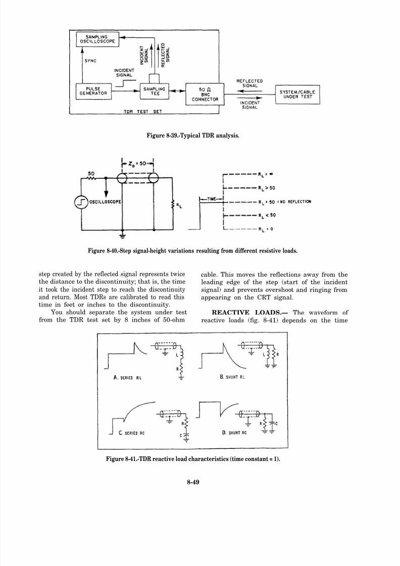
8/14/2019 US Navy Course NAVEDTRA 14028 - Aviation Electronics Technician-Basic
http://slidepdf.com/reader/full/us-navy-course-navedtra-14028-aviation-electronics-technician-basic 344/415
Figure 8-39.-Typical TDR analysis.
Figure 8-40.-Step signal-height variations resulting from different resistive loads.
step created by the reflected signal represents twice cable. This moves the reflections away from thethe distance to the discontinuity; that is, the time leading edge of the step (start of the incidentit took the incident step to reach the discontinuity signal) and prevents overshoot and ringing from
and return. Most TDRs are calibrated to read this appearing on the CRT signal.time in feet or inches to the discontinuity.
You should separate the system under test REACTIVE LOADS.— The waveform of from the TDR test set by 8 inches of 50-ohm reactive loads (fig. 8-41) depends on the time
Figure 8-41.-TDR reactive load characteristics (time constant = 1).
8-49
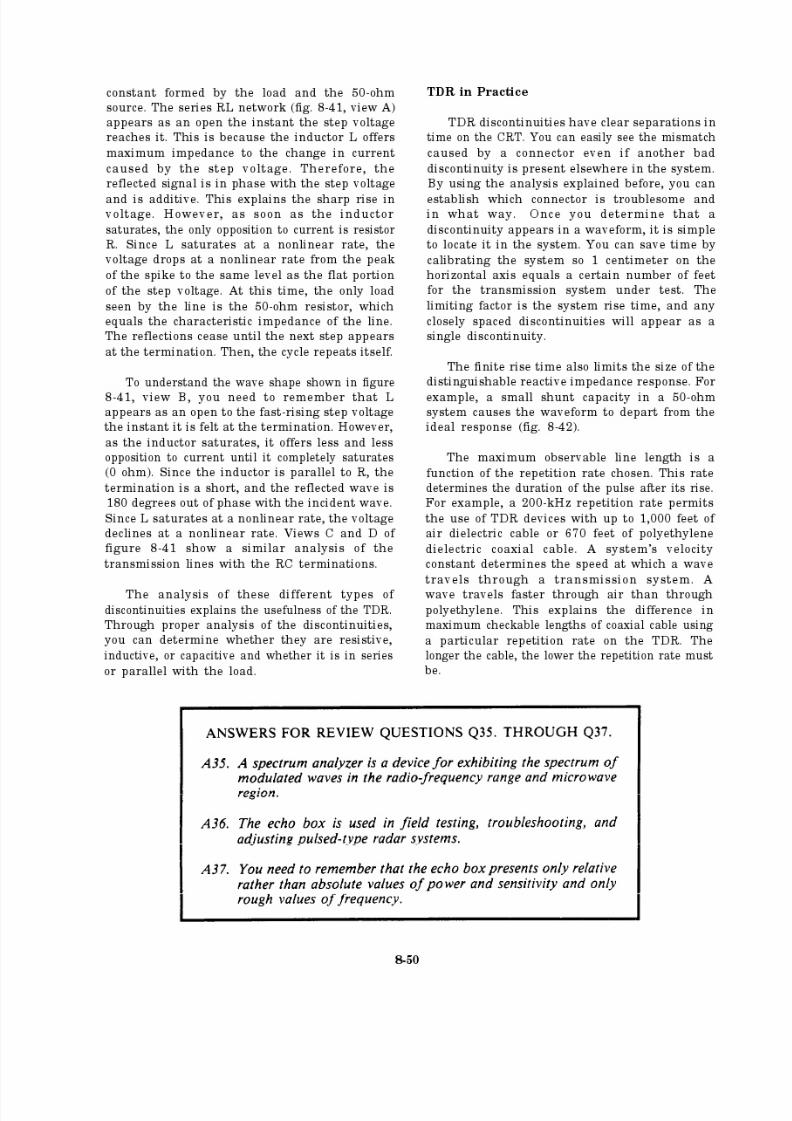
8/14/2019 US Navy Course NAVEDTRA 14028 - Aviation Electronics Technician-Basic
http://slidepdf.com/reader/full/us-navy-course-navedtra-14028-aviation-electronics-technician-basic 345/415

8/14/2019 US Navy Course NAVEDTRA 14028 - Aviation Electronics Technician-Basic
http://slidepdf.com/reader/full/us-navy-course-navedtra-14028-aviation-electronics-technician-basic 346/415
Figure 8-42.-Small shunt capacity in system degrades idealresponse.
Range and Resolution
Assuming that the total impedance equals50 ohms, you may measure a resistance between0.025 ohm and 100 kilohms. Because the heightof the reflection is directly proportional to the
resistance, you may determine the resistance byusing a precalculated transparent overlay.
One common use of the TDR is in analyzinga coaxial cable. The amount of impedance variation that is detectable in a long section of
cable is a function of the flatness of the top of
the incident step. If this step is flat within ±0.5
percent, it can detect an impedance variation of 0.5 ohm along the cable, corresponding to a1 percent check on cable impedance. Thus,
irregularities in cable makeup resulting from variations in the braiding process or tightness of
the insulating jacket show up clearly.
Analyzing Terminations
A departure from 50 ohms in a terminationor cable connector can cause some problems. For
example, large reflections in a pulse system or alarge voltage standing-wave ratio (VSWR) can
occur in a system that carries primarily sinusoidalsignals. Because of human errors in the assembly
process, even the best connectors will cause
reflections or a varying VSWR. Therefore,
expensive connectors do not ensure freedom from
unwanted reflections. However, the TDR helpsyou locate unacceptable connectors by rapidly
showing where the mismatches are and how badthey are. The TDR also indicates if these
connectors are resistive, capacitive, or inductiveand whether series or shunt. Figure 8-43 showsa step being propagated from a section of
RG9A/U into a load. The connector on the load
and the cable are the general radio type 874. It
shows four different cases with varying loads.These cases show how you can analyze the
connection and the load by using the TDR. With
different connectors and loads, the smallmismatches (discontinuities) take on different
Figure 8-43.-Waveforms resulting from the use of differentloads. Horizontal scale 0.4 µsec/cm; vertical scale0.5 percent/cm.
8-51
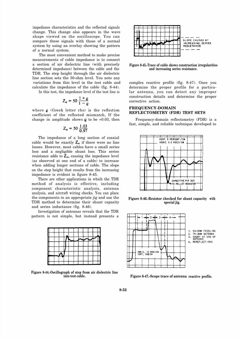
8/14/2019 US Navy Course NAVEDTRA 14028 - Aviation Electronics Technician-Basic
http://slidepdf.com/reader/full/us-navy-course-navedtra-14028-aviation-electronics-technician-basic 347/415
impedance characteristics and the reflected signalschange. This change also appears in the waveshape viewed on the oscilloscope. You can
compare these signals with those of a normalsystem by using an overlay showing the pattern
of a normal system.
The most convenient method to make precise
measurements of cable impedance is to connecta section of air dielectric line (with preciselydetermined impedance) between the cable and theTDR. The step height through the air dielectricline section sets the 50-ohm level. You note any
variations from this level in the test cable and
calculate the impedance of the cable (fig. 8-44).
In this test, the impedance level of the test line is
where (Greek letter rho) is the reflection
coefficient of the reflected mismatch, If the
change in amplitude shows to be +0.03, then
The impedance of a long section of coaxial
cable would be exactly if there were no linelosses. However, most cables have a small seriesloss and a negligible shunt loss. This seriesresistance adds to causing the impedance level
(as observed at one end of a cable) to increasewhen adding longer sections of cable. The slope
on the step height that results from the increasingimpedance is evident in figure 8-45.
There are other applications in which the TDRmethod of analysis is effective, including
component characteristic analysis, antennaanalysis, and aircraft wiring checks. You can placethe components in an appropriate jig and use theTDR method to determine their shunt capacity
and series inductance (fig. 8-46).
Investigation of antennas reveals that the TDRpattern is not simple, but instead presents a
Figure 8-44.-Oscillograph of step from air dielectric lineinto test cable.
Figure 8-45.-Trace of cable shows construction irregularitiesand increasing series resistance.
complex reactive profile (fig. 8-47). Once you
determine the proper profile for a particu-lar antenna, you can detect any improper
construction details and determine the proper
corrective action.
FREQUENCY-DOMAIN
REFLECTOMETRY (FDR) TEST SETS
Frequency-domain reflectometry (FDR) is afast, simple, and reliable technique developed to
Figure 8-46.-Resistor checked for shunt capacityspecial jig.
Figure 8-47.-Scope trace of antenna
with
reactive profile.
8-52
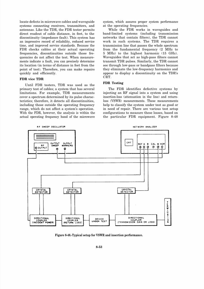
8/14/2019 US Navy Course NAVEDTRA 14028 - Aviation Electronics Technician-Basic
http://slidepdf.com/reader/full/us-navy-course-navedtra-14028-aviation-electronics-technician-basic 348/415
locate defects in microwave cables and waveguide
systems connecting receivers, transmitters, and
antennas. Like the TDR, the FDR tester permits
direct readout of cable distance, in feet, to thediscontinuity (impedance fault). This system hasan impressive record of reliability, reduced service
time, and improved service standards. Because the
FDR checks cables at their actual operatingfrequencies, discontinuities outside those fre-
quencies do not affect the test. When measure-
ments indicate a fault, you can precisely determine
its location (in terms of distance in feet from the
point of test). Therefore, you can make repairsquickly and efficiently.
FDR vice TDR
Until FDR testers, TDR was used as the
primary test of cables; a system that has severallimitations. For example, TDR measurements
cover a spectrum determined by its pulse charac-
teristics; therefore, it detects all discontinuities,including those outside the operating frequency
range, which do not affect a system’s operation.With the FDR, however, the analysis is within the
actual operating frequency band of the microwave
system, which assures proper system performance
at the operating frequencies.
While the FDR works in waveguides andband-limited systems (including transmissionnetworks that contain filters), the TDR cannot
work in such systems. The TDR requires a
transmission line that passes the whole spectrum
from the fundamental frequency (2 MHz to5 MHz) to the highest harmonic (15 GHz).Waveguides that act as high-pass filters cannot
transmit TDR pulses. Similarly, the TDR cannot
see through low-pass or bandpass filters becausethey eliminate the low-frequency harmonics and
appear to display a discontinuity on the TDR’sCRT.
FDR Testing
The FDR identifies defective systems byinjecting an RF signal into a system and using
insertion-loss (attenuation in the line) and return-
loss (VSWR) measurements. These measurementshelp to classify the system under test as good orin need of repair. There are various test setup
configurations to measure these losses, based onthe particular FDR equipment. Figure 8-48
Figure 8-48.-Typical setup for VSWR and insertion performance.
8-53
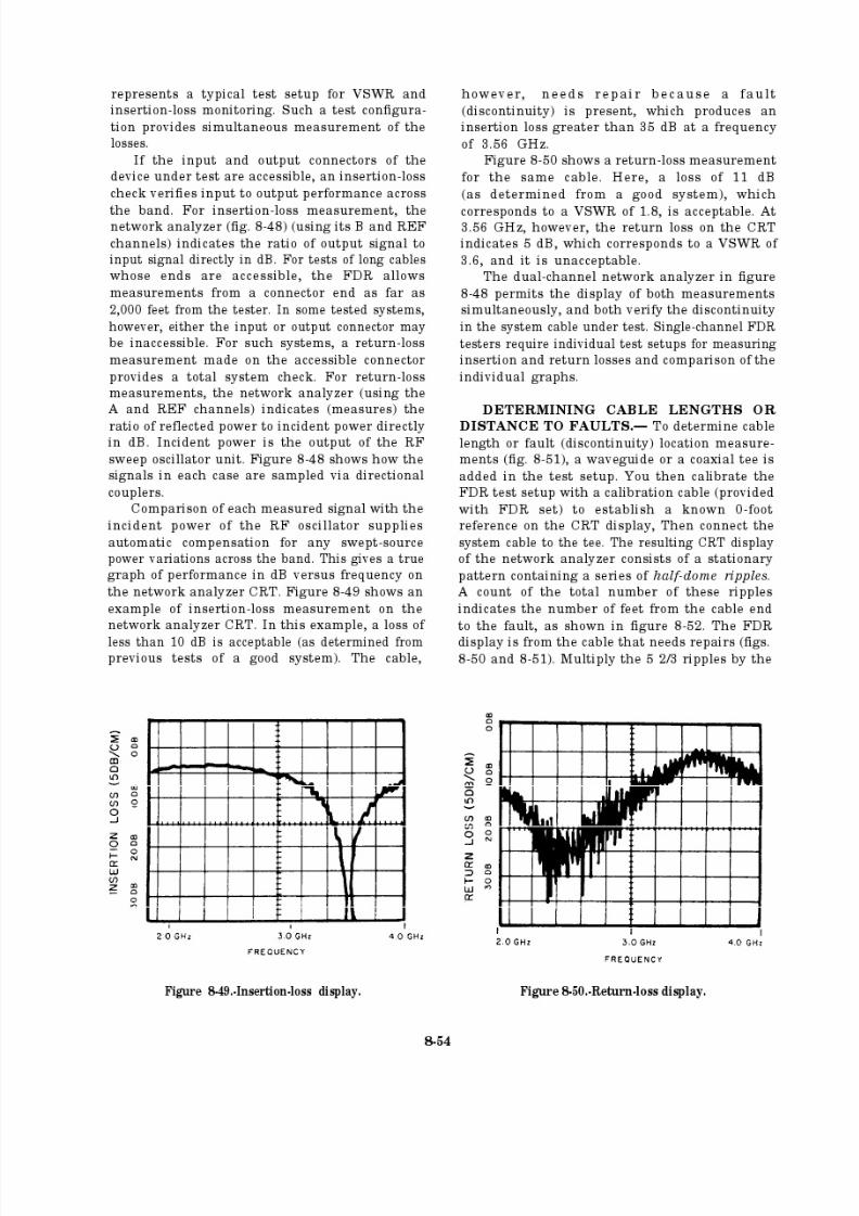
8/14/2019 US Navy Course NAVEDTRA 14028 - Aviation Electronics Technician-Basic
http://slidepdf.com/reader/full/us-navy-course-navedtra-14028-aviation-electronics-technician-basic 349/415

8/14/2019 US Navy Course NAVEDTRA 14028 - Aviation Electronics Technician-Basic
http://slidepdf.com/reader/full/us-navy-course-navedtra-14028-aviation-electronics-technician-basic 350/415
Figure 8-51.-Test setup for fault location measurement.
calibration factor of 2 feet per ripple (CRT to the same tee junction, discontinuities and/or
calibrated that way). You can see that the location
of the fault is 11 1/3 feet from the cable end
connector (5 2/3 x 2 = 11 1/3 ft). Figure 8-53shows a dual-channel display of the cable after
completing the repairs. The insertion loss is lessthan 10 dB and the return loss is greater than 11dB, indicating proper performance of the systemcable.
DETAILED FDR ANALYSIS.— With the
sweep oscillator output, the transmission systemunder test, and the crystal detector all connected
Figure 8-52.-Measuring a cable fault.
termination mismatches in the system reflect some
of the incident power. The reflected power
combines with the incident signal at the crystal
detector, resulting in a changing phase relation-
ship that depends on both distance to thediscontinuity and signal frequency. As thefrequency is swept, it changes the number of wavelengths that occupy the fixed path from the
tee to the point of reflection and back. The display
Figure 8-53.-Dual-channel display of a repaired cable.
8-55

8/14/2019 US Navy Course NAVEDTRA 14028 - Aviation Electronics Technician-Basic
http://slidepdf.com/reader/full/us-navy-course-navedtra-14028-aviation-electronics-technician-basic 351/415
shows amplitude ripples that result from the
summing of the incident and reflected signals.This relationship changes with frequency. Figure
8-54 shows how the magnitude of the vector sumof these signals, which is the signal level detectedfor display, varies with frequency.
The resulting display of the varying-magnitudedetected signal is actually a logarithmic SWR
presentation. The ripple peaks are adjacent VSWR maxima that occur during the sweep. They
occur at each frequency in which the round-trip
length of the reflected wave path from the sourceto the defect has changed by one wavelength. Thenumber of ripples appearing across the full width
of the display is a measure of the distance
from the discontinuity to the crystal detector.
Therefore, a direct readout of fault distance is
available when the swept source operates over asweep width (AF). The sweep width is chosen to
provide a display calibration (in terms of ripplesper foot) compatible with the length of thetransmission system under test.
In a coaxial system, the distance to a
discontinuity, which may be a fault or the cableend, is represented by the equation
Where D is the distance to the fault or cable
end in feet,
492 is the half wavelength in feet of a 1-MHzwave in free space transmission,
K is the propagation constant that relates the
propagation velocity in the coaxial system to
the velocity in free space,
N is the number of ripples observed in the
display, and
AF is the swept-frequency excursion (sweepwidth) of the signal source in MHz.
You should note that for any type of cable,
AF can be selected to equal 492K. The distancein feet is equal to the number of ripples (includingthe fractional ripples) shown in the display.
Figure 8-54.-Magnitude of the vector sum.
8-56
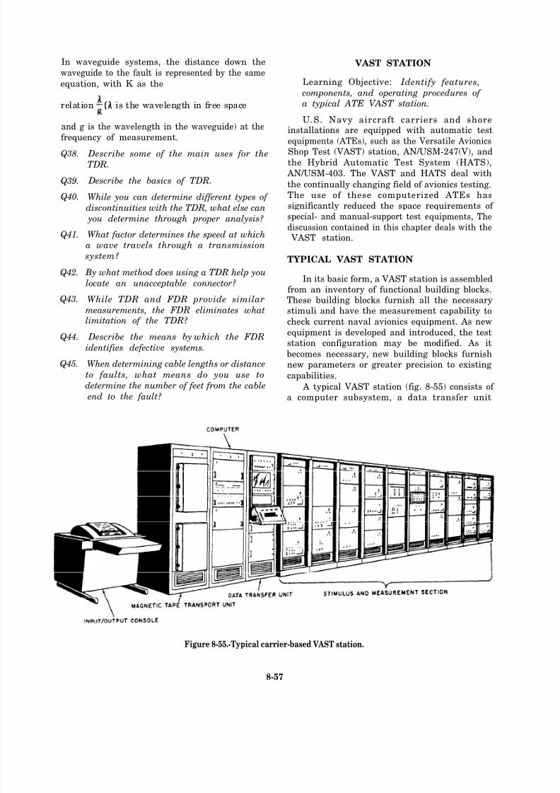
8/14/2019 US Navy Course NAVEDTRA 14028 - Aviation Electronics Technician-Basic
http://slidepdf.com/reader/full/us-navy-course-navedtra-14028-aviation-electronics-technician-basic 352/415
In waveguide systems, the distance down the
waveguide to the fault is represented by the same
equation, with K as the
relation is the wavelength in free space
and g is the wavelength in the waveguide) at the
frequency of measurement.
Q38.
Q39.
Q40.
Q41.
Q42.
Q43.
Q44.
Q45.
Describe some of the main uses for the
TDR.
Describe the basics of TDR.
While you can determine different types of
discontinuities with the TDR, what else can
you determine through proper analysis?
What factor determines the speed at whicha wave travels through a transmission
system?
By what method does using a TDR help you
locate an unacceptable connector?
While TDR and FDR provide similar
measurements, the FDR eliminates whatlimitation of the TDR?
Describe the means by which the FDR
identifies defective systems.
When determining cable lengths or distance
to faults, what means do you use to
determine the number of feet from the cable
end to the fault?
VAST STATION
Learning Objective: Identify features,
components, and operating procedures of a typical ATE VAST station.
U.S. Navy aircraft carriers and shoreinstallations are equipped with automatic test
equipments (ATEs), such as the Versatile AvionicsShop Test (VAST) station, AN/USM-247(V), and
the Hybrid Automatic Test System (HATS),
AN/USM-403. The VAST and HATS deal with
the continually changing field of avionics testing.The use of these computerized ATEs has
significantly reduced the space requirements of special- and manual-support test equipments, The
discussion contained in this chapter deals with the VAST station.
TYPICAL VAST STATION
In its basic form, a VAST station is assembledfrom an inventory of functional building blocks.These building blocks furnish all the necessarystimuli and have the measurement capability to
check current naval avionics equipment. As new
equipment is developed and introduced, the teststation configuration may be modified. As it
becomes necessary, new building blocks furnishnew parameters or greater precision to existing
capabilities.
A typical VAST station (fig. 8-55) consists of a computer subsystem, a data transfer unit
Figure 8-55.-Typical carrier-based V AST station.
8-57

8/14/2019 US Navy Course NAVEDTRA 14028 - Aviation Electronics Technician-Basic
http://slidepdf.com/reader/full/us-navy-course-navedtra-14028-aviation-electronics-technician-basic 353/415
(DTU), and a stimulus and measurement section
containing functional building blocks configuredto meet the intended test application.
A computer subsystem controls the test
station, which executes test programs to assure
accurate and satisfactory testing. The computer
subsystem includes a general-purpose digital
computer that executes test routines and hasdiagnostic and computational capabilities. Also,
this subsystem processes data and furnishes apermanent record of test results. Two magnetictape transports provide rapid access to avionics
test programs and immediate availability of VASTself-check programs.
The data transfer unit (DTU) (fig. 8-56) serves
as the operator-machine interface. It synchronizesinstructions and data flow between the computer
and the functional building blocks. Also, itcontains the display and control panels.
The operator communicates with the com-puter and the stimulus and measurement section
of the VAST system by using the DTU control
panel, which has the keyboard and mode selectkey. The test station may be operated in
three modes—manual, semiautomatic, or fullyautomatic.
The DTU contains a maintenance panel that
monitors station auto-check results and indicatesbuilding block faults. Transmission of instructionsfrom the control computer is on a request/
acknowledge basis. Essentially, the stimulus and
measurement section controls the response rate.
This allows instructions to be transmitted at
an asynchronous rate, corresponding to the
8-58

8/14/2019 US Navy Course NAVEDTRA 14028 - Aviation Electronics Technician-Basic
http://slidepdf.com/reader/full/us-navy-course-navedtra-14028-aviation-electronics-technician-basic 354/415
Figure 8-56.-Data transfer unit (DTU).
maximum frequency at which a given buildingblock or avionics unit can respond. Therefore,
there is no requirement for immediate programstorage in the DTU.
FEATURES OF A VAST STATION
A VAST station may have as many as 14 racksof stimulus and measurement building blocks
(fig. 8-57). Large station configurations may
contain as many as 17 core building blocks. Core
building blocks are designated as a result of high-use factors or because they are needed forself-test requirements. Building blocks not in the
core category are usually selected to meet thespecific test requirements of shop operations or
avionics equipment on board ship. In general, thelocation of such peripheral building blocks is
flexible. To maintain standardization between VAST stations, the effects of building block
interconnection cable losses and switches have toremain within predictable limits; this is the
purpose of the core concept.Ease of maintenance is the main objective of
the VAST station designed. In addition to the
modularized design of VAST building blocks,there are three levels of fault detection, which
ensure rapid confidence tests and easy fault
location. The three levels of detection are
auto-check. self-check, and self-test.Fault detection may be initially made through
auto-check. The auto-check is inherent in the logicand control design of the test station and includes
Figure 8-57.-VAST station with building blocks.
8-59
8/14/2019 US Navy Course NAVEDTRA 14028 - Aviation Electronics Technician-Basic
http://slidepdf.com/reader/full/us-navy-course-navedtra-14028-aviation-electronics-technician-basic 355/415
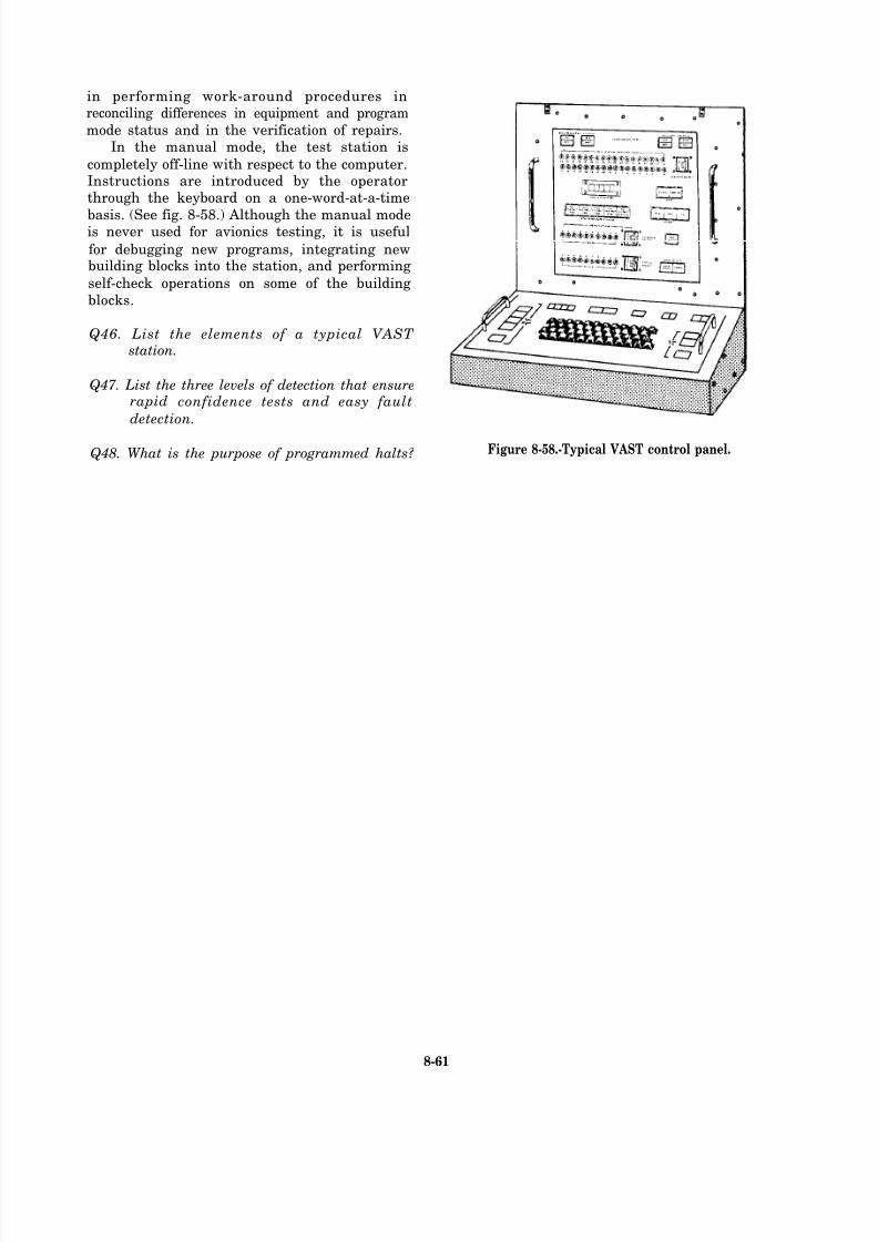
8/14/2019 US Navy Course NAVEDTRA 14028 - Aviation Electronics Technician-Basic
http://slidepdf.com/reader/full/us-navy-course-navedtra-14028-aviation-electronics-technician-basic 356/415
in performing work-around procedures inreconciling differences in equipment and program
mode status and in the verification of repairs.In the manual mode, the test station is
completely off-line with respect to the computer.Instructions are introduced by the operatorthrough the keyboard on a one-word-at-a-time
basis. (See fig. 8-58.) Although the manual modeis never used for avionics testing, it is useful
for debugging new programs, integrating newbuilding blocks into the station, and performing
self-check operations on some of the building
blocks.
Q46. List the elements of a typical VAST station.
Q47. List the three levels of detection that ensurerapid confidence tests and easy fault
detection.
Q48. What is the purpose of programmed halts? Figure 8-58.-Typical VAST control panel.
8-61

8/14/2019 US Navy Course NAVEDTRA 14028 - Aviation Electronics Technician-Basic
http://slidepdf.com/reader/full/us-navy-course-navedtra-14028-aviation-electronics-technician-basic 357/415
8-62

8/14/2019 US Navy Course NAVEDTRA 14028 - Aviation Electronics Technician-Basic
http://slidepdf.com/reader/full/us-navy-course-navedtra-14028-aviation-electronics-technician-basic 358/415
8/14/2019 US Navy Course NAVEDTRA 14028 - Aviation Electronics Technician-Basic
http://slidepdf.com/reader/full/us-navy-course-navedtra-14028-aviation-electronics-technician-basic 359/415
8/14/2019 US Navy Course NAVEDTRA 14028 - Aviation Electronics Technician-Basic
http://slidepdf.com/reader/full/us-navy-course-navedtra-14028-aviation-electronics-technician-basic 360/415
8/14/2019 US Navy Course NAVEDTRA 14028 - Aviation Electronics Technician-Basic
http://slidepdf.com/reader/full/us-navy-course-navedtra-14028-aviation-electronics-technician-basic 361/415
8/14/2019 US Navy Course NAVEDTRA 14028 - Aviation Electronics Technician-Basic
http://slidepdf.com/reader/full/us-navy-course-navedtra-14028-aviation-electronics-technician-basic 362/415
8/14/2019 US Navy Course NAVEDTRA 14028 - Aviation Electronics Technician-Basic
http://slidepdf.com/reader/full/us-navy-course-navedtra-14028-aviation-electronics-technician-basic 363/415
8/14/2019 US Navy Course NAVEDTRA 14028 - Aviation Electronics Technician-Basic
http://slidepdf.com/reader/full/us-navy-course-navedtra-14028-aviation-electronics-technician-basic 364/415
8/14/2019 US Navy Course NAVEDTRA 14028 - Aviation Electronics Technician-Basic
http://slidepdf.com/reader/full/us-navy-course-navedtra-14028-aviation-electronics-technician-basic 365/415
8/14/2019 US Navy Course NAVEDTRA 14028 - Aviation Electronics Technician-Basic
http://slidepdf.com/reader/full/us-navy-course-navedtra-14028-aviation-electronics-technician-basic 366/415
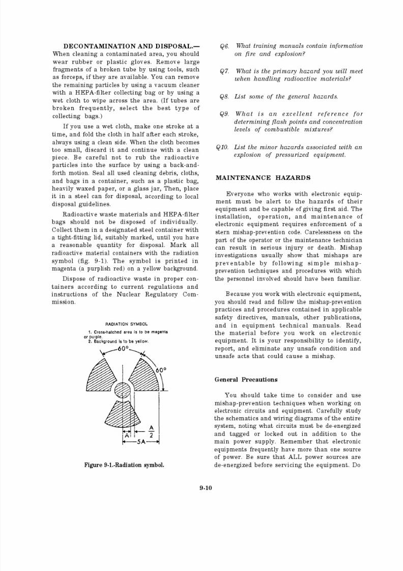
8/14/2019 US Navy Course NAVEDTRA 14028 - Aviation Electronics Technician-Basic
http://slidepdf.com/reader/full/us-navy-course-navedtra-14028-aviation-electronics-technician-basic 367/415
8/14/2019 US Navy Course NAVEDTRA 14028 - Aviation Electronics Technician-Basic
http://slidepdf.com/reader/full/us-navy-course-navedtra-14028-aviation-electronics-technician-basic 368/415
8/14/2019 US Navy Course NAVEDTRA 14028 - Aviation Electronics Technician-Basic
http://slidepdf.com/reader/full/us-navy-course-navedtra-14028-aviation-electronics-technician-basic 369/415
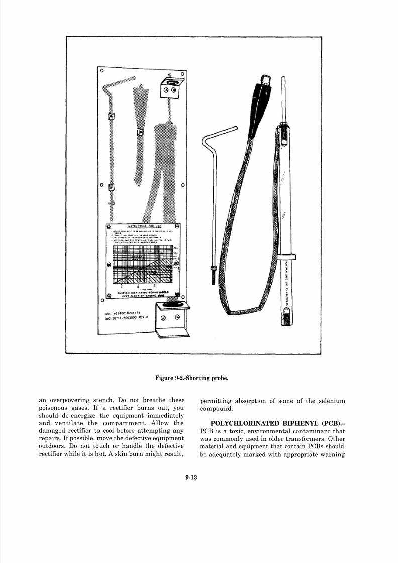
8/14/2019 US Navy Course NAVEDTRA 14028 - Aviation Electronics Technician-Basic
http://slidepdf.com/reader/full/us-navy-course-navedtra-14028-aviation-electronics-technician-basic 370/415
Figure 9-2.-Shorting probe.
an overpowering stench. Do not breathe these permitting absorption of some of the seleniumpoisonous gases. If a rectifier burns out, you compound.should de-energize the equipment immediatelyand ventilate the compartment. Allow the POLYCHLORINATED BIPHENYL (PCB).–damaged rectifier to cool before attempting any PCB is a toxic, environmental contaminant thatrepairs. If possible, move the defective equipment was commonly used in older transformers. Otheroutdoors. Do not touch or handle the defective material and equipment that contain PCBs shouldrectifier while it is hot. A skin burn might result, be adequately marked with appropriate warning
9-13
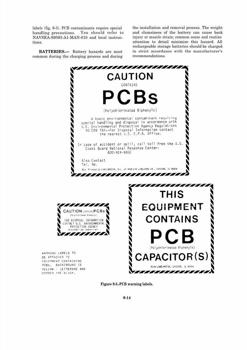
8/14/2019 US Navy Course NAVEDTRA 14028 - Aviation Electronics Technician-Basic
http://slidepdf.com/reader/full/us-navy-course-navedtra-14028-aviation-electronics-technician-basic 371/415
labels (fig, 9-3). PCB contaminants require special the installation and removal process. The weight
handling precautions. You should refer to and clumsiness of the battery can cause back
NAVSEA-S9593-A1-MAN-010 and local instruc- injury or muscle strain; common sense and routine
tions. attention to detail minimize this hazard. Allrechargeable storage batteries should be charged
BATTERIES.— Battery hazards are most in strict accordance with the manufacturer’s
common during the charging process and during recommendations.
Figure 9-3.-PCB warning labels.
9-14
8/14/2019 US Navy Course NAVEDTRA 14028 - Aviation Electronics Technician-Basic
http://slidepdf.com/reader/full/us-navy-course-navedtra-14028-aviation-electronics-technician-basic 372/415

8/14/2019 US Navy Course NAVEDTRA 14028 - Aviation Electronics Technician-Basic
http://slidepdf.com/reader/full/us-navy-course-navedtra-14028-aviation-electronics-technician-basic 373/415
8/14/2019 US Navy Course NAVEDTRA 14028 - Aviation Electronics Technician-Basic
http://slidepdf.com/reader/full/us-navy-course-navedtra-14028-aviation-electronics-technician-basic 374/415
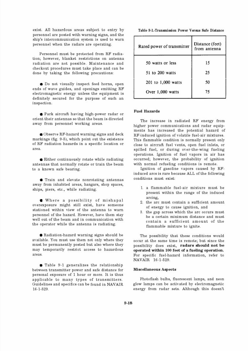
8/14/2019 US Navy Course NAVEDTRA 14028 - Aviation Electronics Technician-Basic
http://slidepdf.com/reader/full/us-navy-course-navedtra-14028-aviation-electronics-technician-basic 375/415

8/14/2019 US Navy Course NAVEDTRA 14028 - Aviation Electronics Technician-Basic
http://slidepdf.com/reader/full/us-navy-course-navedtra-14028-aviation-electronics-technician-basic 376/415
Figure 9-5.-RF hazard warnings.
happen often, personnel should be warned of the exposed to radiation. With some high-power radarpresence of any high-power radar operating in the sets, steel wool ignites with a violent explosion.
area and of the hazards involved. The presence of oils and spilled fuels in the vicinity
In a similar manner, steel wool may be set of aircraft constitutes a serious hazard. This
afire, or metallic chips may produce sparks when makes good housekeeping procedures essential.
9-19
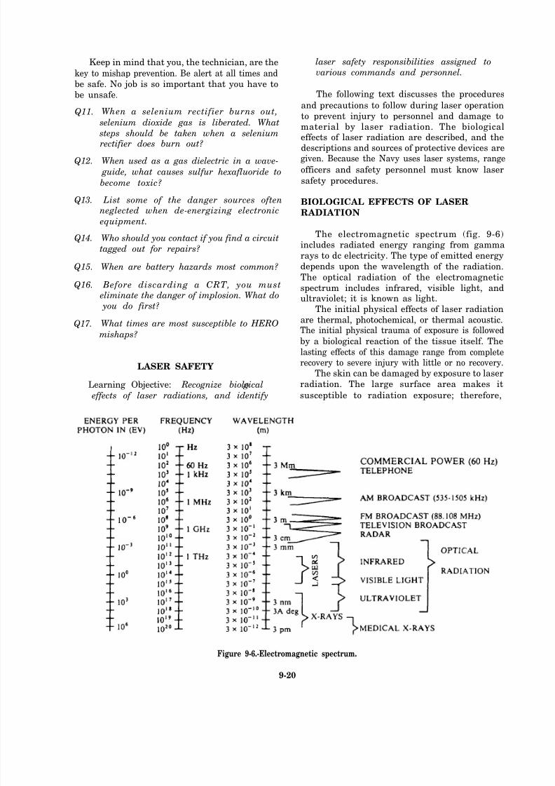
8/14/2019 US Navy Course NAVEDTRA 14028 - Aviation Electronics Technician-Basic
http://slidepdf.com/reader/full/us-navy-course-navedtra-14028-aviation-electronics-technician-basic 377/415
Keep in mind that you, the technician, are the
key to mishap prevention. Be alert at all times and
be safe. No job is so important that you have to
be unsafe.
Q11.
Q12.
Q13.
Q14.
Q15.
Q16.
Q17.
When a selenium rectifier burns out,
selenium dioxide gas is liberated. What
steps should be taken when a seleniumrectifier does burn out?
When used as a gas dielectric in a wave-
guide, what causes sulfur hexafluoride to
become toxic?
List some of the danger sources oftenneglected when de-energizing electronic
equipment.
Who should you contact if you find a circuit
tagged out for repairs?
When are battery hazards most common?
Before discarding a CRT, you must eliminate the danger of implosion. What do
you do first?
What times are most susceptible to HERO
mishaps?
LASER SAFETY
Learning Objective: Recognize biolo gical
effects of laser radiations, and identify
laser safety responsibilities assigned to
various commands and personnel.
The following text discusses the procedures
and precautions to follow during laser operation
to prevent injury to personnel and damage tomaterial by laser radiation. The biological
effects of laser radiation are described, and thedescriptions and sources of protective devices aregiven. Because the Navy uses laser systems, range
officers and safety personnel must know laser
safety procedures.
BIOLOGICAL EFFECTS OF LASER
RADIATION
The electromagnetic spectrum (fig. 9-6)includes radiated energy ranging from gamma
rays to dc electricity. The type of emitted energy
depends upon the wavelength of the radiation.
The optical radiation of the electromagneticspectrum includes infrared, visible light, andultraviolet; it is known as light.
The initial physical effects of laser radiation
are thermal, photochemical, or thermal acoustic.The initial physical trauma of exposure is followed
by a biological reaction of the tissue itself. The
lasting effects of this damage range from completerecovery to severe injury with little or no recovery.
The skin can be damaged by exposure to laser
radiation. The large surface area makes it
susceptible to radiation exposure; therefore,
Figure 9-6.-Electromagnetic spectrum.
9-20
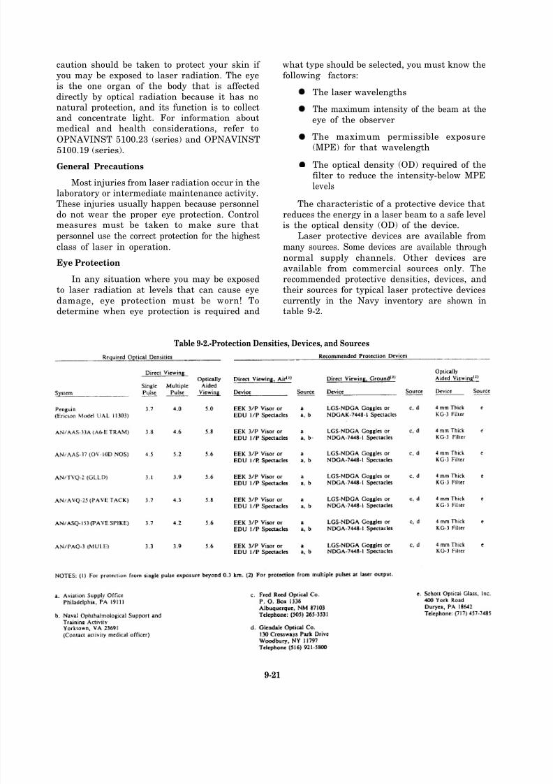
8/14/2019 US Navy Course NAVEDTRA 14028 - Aviation Electronics Technician-Basic
http://slidepdf.com/reader/full/us-navy-course-navedtra-14028-aviation-electronics-technician-basic 378/415
caution should be taken to protect your skin if
you may be exposed to laser radiation. The eyeis the one organ of the body that is affected
directly by optical radiation because it has nonatural protection, and its function is to collectand concentrate light. For information aboutmedical and health considerations, refer to
OPNAVINST 5100.23 (series) and OPNAVINST5100.19 (series).
General Precautions
Most injuries from laser radiation occur in thelaboratory or intermediate maintenance activity.These injuries usually happen because personnel
do not wear the proper eye protection. Controlmeasures must be taken to make sure that
personnel use the correct protection for the highest
class of laser in operation.
Eye Protection
In any situation where you may be exposed
to laser radiation at levels that can cause eye
damage, eye protection must be worn! Todetermine when eye protection is required and
what type should be selected, you must know the
following factors:
The laser wavelengths
The maximum intensity of the beam at the
eye of the observer
The maximum permissible exposure(MPE) for that wa velength
The optical density (OD) required of the
filter to reduce the intensity-below MPElevels
The characteristic of a protective device that
reduces the energy in a laser beam to a safe levelis the optical density (OD) of the device.
Laser protective devices are available from
many sources. Some devices are available through
normal supply channels. Other devices are
available from commercial sources only. Therecommended protective densities, devices, and
their sources for typical laser protective devices
currently in the Navy inventory are shown intable 9-2.
Table 9-2.-Protection Densities, Devices, and Sources
9-21
8/14/2019 US Navy Course NAVEDTRA 14028 - Aviation Electronics Technician-Basic
http://slidepdf.com/reader/full/us-navy-course-navedtra-14028-aviation-electronics-technician-basic 379/415
When assigned to a laser system, ensure that LASER SAFETY RESPONSIBILITIES
you obtain and observe all additional precautionslisted in the applicable maintenance instructions The safety responsibilities for the various
manual. To minimize the danger of laser devices, commands and personnel are discussed in the
you should always follow these general practices: following paragraphs.
1.
2.
3.
4.
5.
6.
7.
8.
9.
10.
11.
Use laser equipment properly.
Know laser hazards.
Ensure research laboratory areas andmaintenance shops are closed areas.
Wear goggles or filter-type goggles when
working with lasers.
Do NOT look directly at an operatinglaser or its reflection in any type of
operation.
Avoid all contact between the skin and the
laser beam.
Report any concern or anxiety about
possible or existing exposure to laserradiation to appropriate medical
personnel.
Do NOT look directly at the pump source.
Use countdown procedures.
Ensure a minimum of two people arepresent whenever the laser is operating.
Identify laser areas properly by posting
Space and Naval Warfare
Systems Command
Space and Naval Warfare Systems Commandis the lead agency for laser safety in the Navy. It
exercises technical direction over laser safety both
afloat and ashore [See SPAWARINST 5100.12
(series)]. The command is responsible for directingand coordinating the following:
The establishment of Navy laser safetydesign standards, documentation, andoperational guidance
Surveys, reviews, and measurements and
safety certification of laser target areas,laser systems, and installations
Reviews of laser systems by the Navy LaserSafety Review Board (LSRB)
The development of laser protective
warning signs (figs. 9-7 and 9-8). devices-
9-22
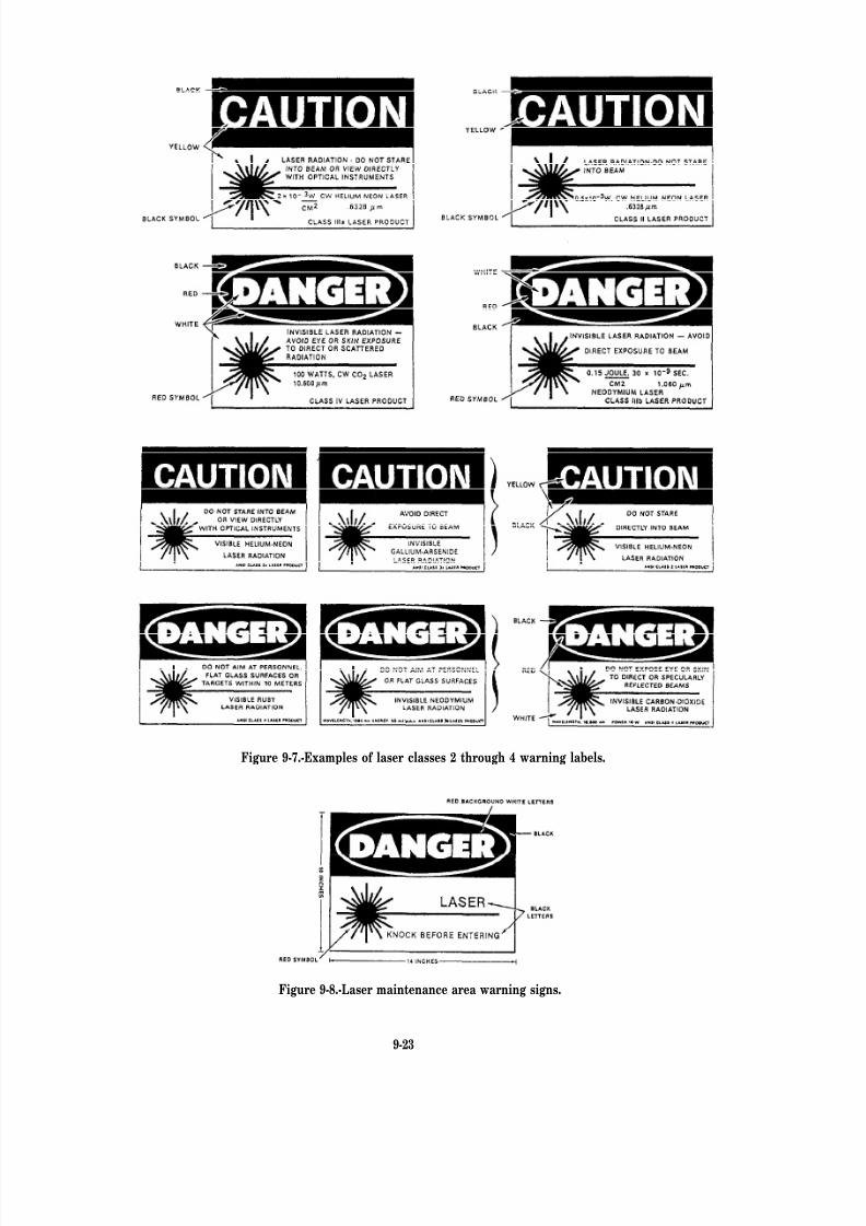
8/14/2019 US Navy Course NAVEDTRA 14028 - Aviation Electronics Technician-Basic
http://slidepdf.com/reader/full/us-navy-course-navedtra-14028-aviation-electronics-technician-basic 380/415
Figure 9-7.-Examples of laser classes 2 through 4 warning labels.
Figure 9-8.-Laser maintenance area warning signs.
9-23

8/14/2019 US Navy Course NAVEDTRA 14028 - Aviation Electronics Technician-Basic
http://slidepdf.com/reader/full/us-navy-course-navedtra-14028-aviation-electronics-technician-basic 381/415
8/14/2019 US Navy Course NAVEDTRA 14028 - Aviation Electronics Technician-Basic
http://slidepdf.com/reader/full/us-navy-course-navedtra-14028-aviation-electronics-technician-basic 382/415
8/14/2019 US Navy Course NAVEDTRA 14028 - Aviation Electronics Technician-Basic
http://slidepdf.com/reader/full/us-navy-course-navedtra-14028-aviation-electronics-technician-basic 383/415
8/14/2019 US Navy Course NAVEDTRA 14028 - Aviation Electronics Technician-Basic
http://slidepdf.com/reader/full/us-navy-course-navedtra-14028-aviation-electronics-technician-basic 384/415

8/14/2019 US Navy Course NAVEDTRA 14028 - Aviation Electronics Technician-Basic
http://slidepdf.com/reader/full/us-navy-course-navedtra-14028-aviation-electronics-technician-basic 385/415
8/14/2019 US Navy Course NAVEDTRA 14028 - Aviation Electronics Technician-Basic
http://slidepdf.com/reader/full/us-navy-course-navedtra-14028-aviation-electronics-technician-basic 386/415
8/14/2019 US Navy Course NAVEDTRA 14028 - Aviation Electronics Technician-Basic
http://slidepdf.com/reader/full/us-navy-course-navedtra-14028-aviation-electronics-technician-basic 387/415
8/14/2019 US Navy Course NAVEDTRA 14028 - Aviation Electronics Technician-Basic
http://slidepdf.com/reader/full/us-navy-course-navedtra-14028-aviation-electronics-technician-basic 388/415
8/14/2019 US Navy Course NAVEDTRA 14028 - Aviation Electronics Technician-Basic
http://slidepdf.com/reader/full/us-navy-course-navedtra-14028-aviation-electronics-technician-basic 389/415
9-32
8/14/2019 US Navy Course NAVEDTRA 14028 - Aviation Electronics Technician-Basic
http://slidepdf.com/reader/full/us-navy-course-navedtra-14028-aviation-electronics-technician-basic 390/415
8/14/2019 US Navy Course NAVEDTRA 14028 - Aviation Electronics Technician-Basic
http://slidepdf.com/reader/full/us-navy-course-navedtra-14028-aviation-electronics-technician-basic 391/415
8/14/2019 US Navy Course NAVEDTRA 14028 - Aviation Electronics Technician-Basic
http://slidepdf.com/reader/full/us-navy-course-navedtra-14028-aviation-electronics-technician-basic 392/415
8/14/2019 US Navy Course NAVEDTRA 14028 - Aviation Electronics Technician-Basic
http://slidepdf.com/reader/full/us-navy-course-navedtra-14028-aviation-electronics-technician-basic 393/415

8/14/2019 US Navy Course NAVEDTRA 14028 - Aviation Electronics Technician-Basic
http://slidepdf.com/reader/full/us-navy-course-navedtra-14028-aviation-electronics-technician-basic 394/415
8/14/2019 US Navy Course NAVEDTRA 14028 - Aviation Electronics Technician-Basic
http://slidepdf.com/reader/full/us-navy-course-navedtra-14028-aviation-electronics-technician-basic 395/415
8/14/2019 US Navy Course NAVEDTRA 14028 - Aviation Electronics Technician-Basic
http://slidepdf.com/reader/full/us-navy-course-navedtra-14028-aviation-electronics-technician-basic 396/415
8/14/2019 US Navy Course NAVEDTRA 14028 - Aviation Electronics Technician-Basic
http://slidepdf.com/reader/full/us-navy-course-navedtra-14028-aviation-electronics-technician-basic 397/415
8/14/2019 US Navy Course NAVEDTRA 14028 - Aviation Electronics Technician-Basic
http://slidepdf.com/reader/full/us-navy-course-navedtra-14028-aviation-electronics-technician-basic 398/415
8/14/2019 US Navy Course NAVEDTRA 14028 - Aviation Electronics Technician-Basic
http://slidepdf.com/reader/full/us-navy-course-navedtra-14028-aviation-electronics-technician-basic 399/415
TRIGGERING—Starting an action in another
circuit, which then operates for a time under its
own control.
TRUE BEARING—A bearing given in relation
to true geographic north. See also BEARING.
TUMBLE (GYRO)—To subject a gyro to atorque so that it presents a precession violent
enough to cause the gyro rotor to spin end over
end.
VELOCITY—A vector quantity that includes
both magnitude (speed) and direction in relation
to a given frame of reference.
VERTICAL PLANE—A vertical plane is
perpendicular to the horizontal plane, and is thereference from which bearings are measured.
Relative bearing, for example, is measured in the
horizontal plane clockwise from the vertical planethrough own ship’s centerline to the vertical planethrough the line of sight. The system of planesmakes possible the design and construction of
mechanical and electronic equipment to solve thefire control problem. These lines and planes are
imaginary extensions of some characteristic of the
ship or target, or of the relation in space between
them.
WAVEGUIDE—Metal tubes or dielectric
cylinders capable of propagating electromagneticwaves through their interiors. The dimensions of
these devices are determined by the frequency
to be propagated. Metal guides are usuallyrectangular or circular in cross section; they
may be evacuated, air filled, or gas filled, and
may or may not be pressurized. Dielectric guides
consist of solid dielectric cylinders surrounded byair.
WAVELENGTH—The distance traveled by
a wave during the time interval of one completecycle, It is equal to the velocity divided by the
frequency.
WAVE PROPAGATION—The radiation, as
from an antenna, of RF energy into space, or of sound energy into a conducting medium.
WORD—In computers, a particular number
of characters handled as a unit by the computerand having a specif ic meaning with respect to the
computation process.
AI-10

8/14/2019 US Navy Course NAVEDTRA 14028 - Aviation Electronics Technician-Basic
http://slidepdf.com/reader/full/us-navy-course-navedtra-14028-aviation-electronics-technician-basic 400/415
APPENDIX II
SYMBOLS, FORMULAS, ANDMEASUREMENTS
AII-1

8/14/2019 US Navy Course NAVEDTRA 14028 - Aviation Electronics Technician-Basic
http://slidepdf.com/reader/full/us-navy-course-navedtra-14028-aviation-electronics-technician-basic 401/415
SYMBOLS
(SEE ANSI/IEEE STD Y32.2-1975 AND 315A-1986)
AII-2

8/14/2019 US Navy Course NAVEDTRA 14028 - Aviation Electronics Technician-Basic
http://slidepdf.com/reader/full/us-navy-course-navedtra-14028-aviation-electronics-technician-basic 402/415
AII-3

8/14/2019 US Navy Course NAVEDTRA 14028 - Aviation Electronics Technician-Basic
http://slidepdf.com/reader/full/us-navy-course-navedtra-14028-aviation-electronics-technician-basic 403/415
AII-4
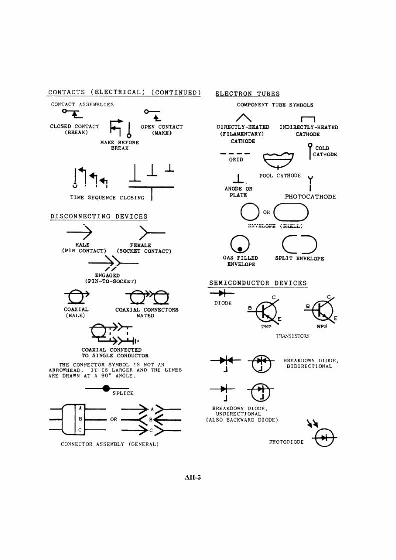
8/14/2019 US Navy Course NAVEDTRA 14028 - Aviation Electronics Technician-Basic
http://slidepdf.com/reader/full/us-navy-course-navedtra-14028-aviation-electronics-technician-basic 404/415
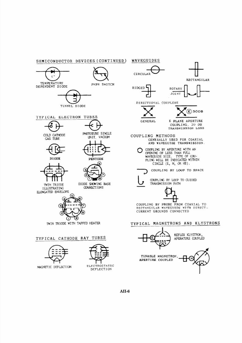
8/14/2019 US Navy Course NAVEDTRA 14028 - Aviation Electronics Technician-Basic
http://slidepdf.com/reader/full/us-navy-course-navedtra-14028-aviation-electronics-technician-basic 405/415
AII-6
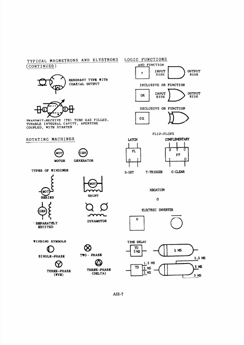
8/14/2019 US Navy Course NAVEDTRA 14028 - Aviation Electronics Technician-Basic
http://slidepdf.com/reader/full/us-navy-course-navedtra-14028-aviation-electronics-technician-basic 406/415
AII-7
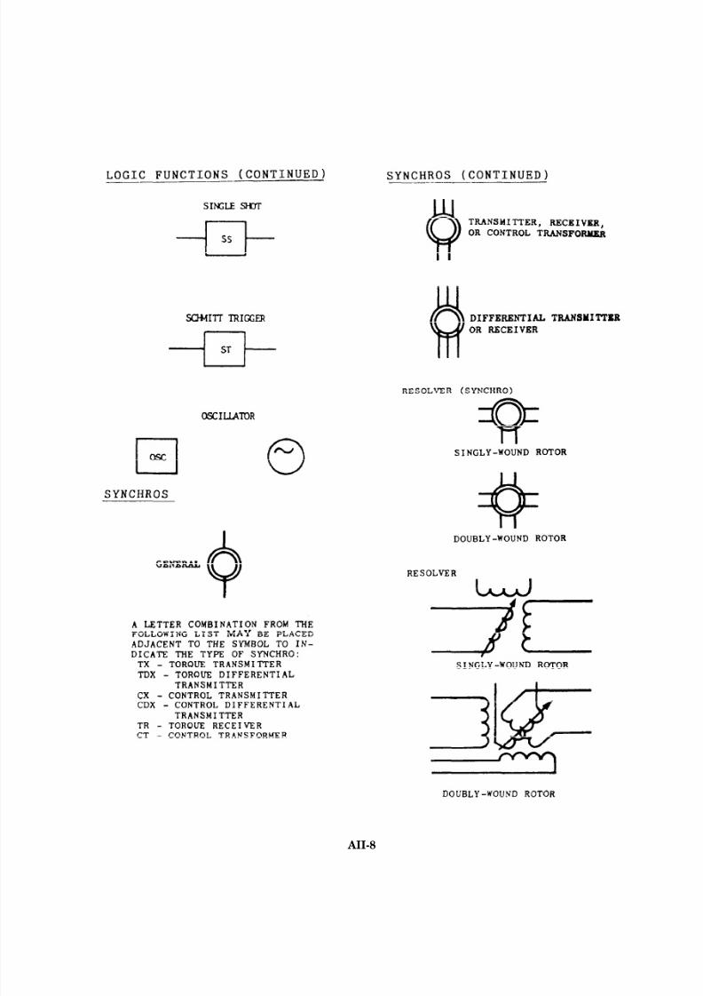
8/14/2019 US Navy Course NAVEDTRA 14028 - Aviation Electronics Technician-Basic
http://slidepdf.com/reader/full/us-navy-course-navedtra-14028-aviation-electronics-technician-basic 407/415
AII-8
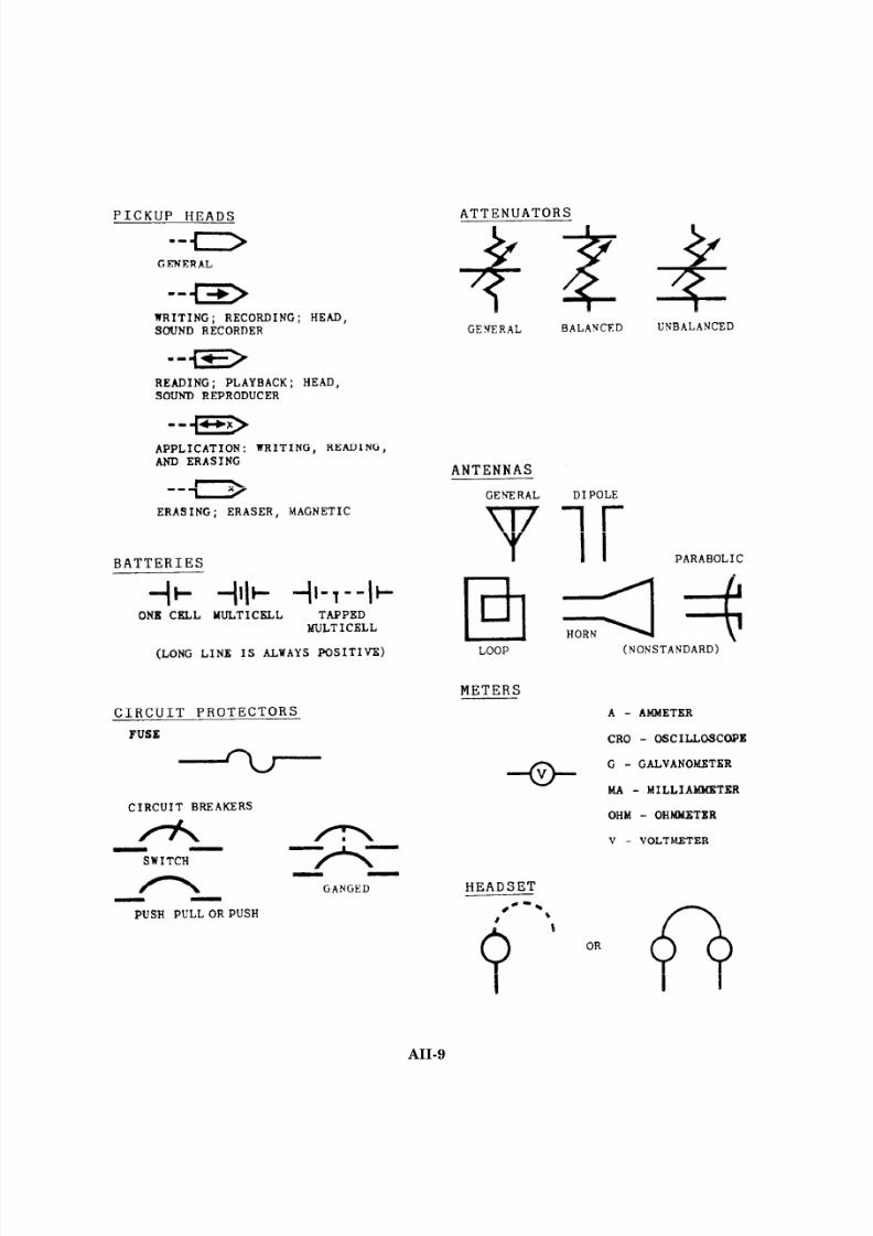
8/14/2019 US Navy Course NAVEDTRA 14028 - Aviation Electronics Technician-Basic
http://slidepdf.com/reader/full/us-navy-course-navedtra-14028-aviation-electronics-technician-basic 408/415
AII-9
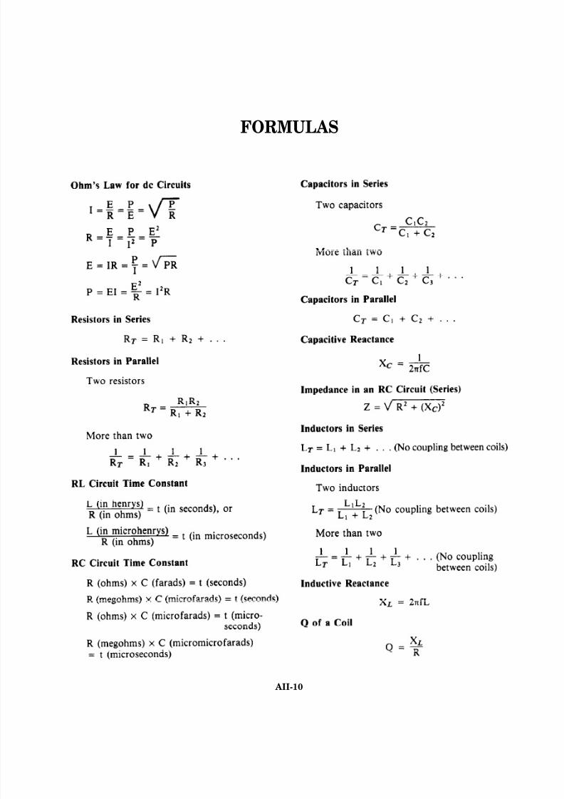
8/14/2019 US Navy Course NAVEDTRA 14028 - Aviation Electronics Technician-Basic
http://slidepdf.com/reader/full/us-navy-course-navedtra-14028-aviation-electronics-technician-basic 409/415
FORMULAS
AII-10

8/14/2019 US Navy Course NAVEDTRA 14028 - Aviation Electronics Technician-Basic
http://slidepdf.com/reader/full/us-navy-course-navedtra-14028-aviation-electronics-technician-basic 410/415
AII-11

8/14/2019 US Navy Course NAVEDTRA 14028 - Aviation Electronics Technician-Basic
http://slidepdf.com/reader/full/us-navy-course-navedtra-14028-aviation-electronics-technician-basic 411/415
AII-12
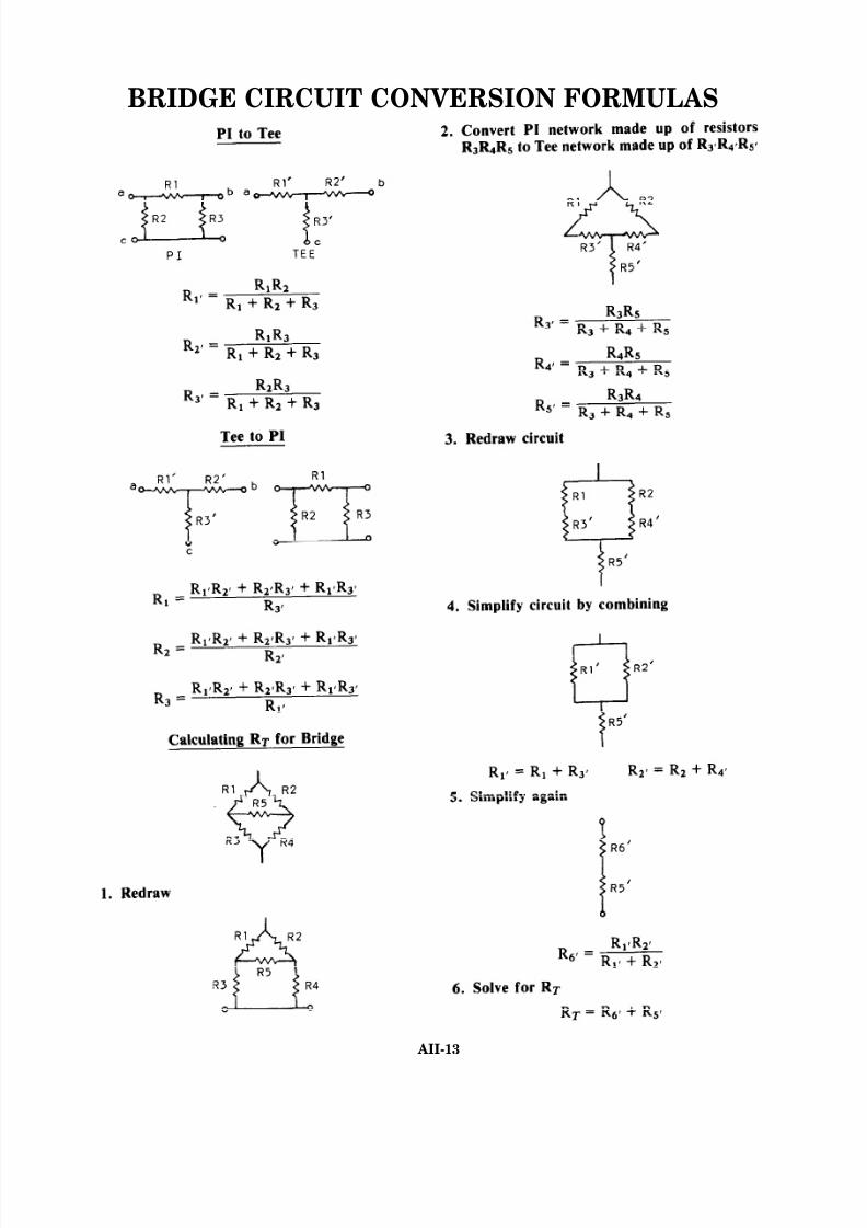
8/14/2019 US Navy Course NAVEDTRA 14028 - Aviation Electronics Technician-Basic
http://slidepdf.com/reader/full/us-navy-course-navedtra-14028-aviation-electronics-technician-basic 412/415
BRIDGE CIRCUIT CONVERSION FORMULAS
AII-13
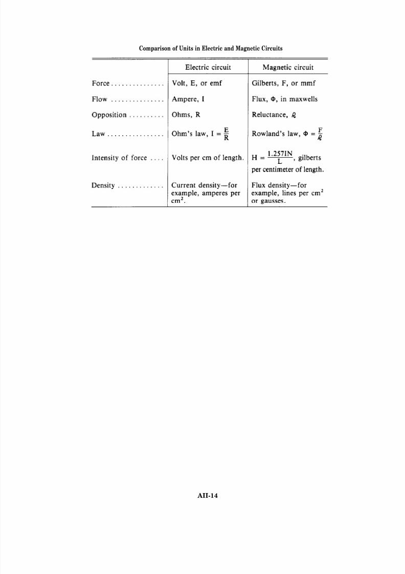
8/14/2019 US Navy Course NAVEDTRA 14028 - Aviation Electronics Technician-Basic
http://slidepdf.com/reader/full/us-navy-course-navedtra-14028-aviation-electronics-technician-basic 413/415
Comparison of Units in Electric and Magnetic Circuits
AII-14
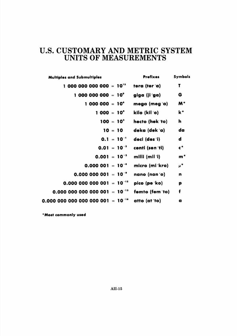
8/14/2019 US Navy Course NAVEDTRA 14028 - Aviation Electronics Technician-Basic
http://slidepdf.com/reader/full/us-navy-course-navedtra-14028-aviation-electronics-technician-basic 414/415
U.S. CUSTOMARY AND METRIC SYSTEM
UNITS OF MEASUREMENTS
AII-15

8/14/2019 US Navy Course NAVEDTRA 14028 - Aviation Electronics Technician-Basic
http://slidepdf.com/reader/full/us-navy-course-navedtra-14028-aviation-electronics-technician-basic 415/415
GREEK ALPHABET