us navy course navedtra 14115 - gas turbine systems technician mechanical) 2
TRANSCRIPT

8/14/2019 US Navy Course NAVEDTRA 14115 - Gas Turbine Systems Technician Mechanical) 2
http://slidepdf.com/reader/full/us-navy-course-navedtra-14115-gas-turbine-systems-technician-mechanical 1/349
DISTRIBUTION STATEMENT A: Approved for public release; distribution is unlimited.
NONRESIDENTTRAINING
COURSEFebruary 1993
Gas Turbine Systems
Technician(Mechanical) 2
NAVEDTRA 14115

8/14/2019 US Navy Course NAVEDTRA 14115 - Gas Turbine Systems Technician Mechanical) 2
http://slidepdf.com/reader/full/us-navy-course-navedtra-14115-gas-turbine-systems-technician-mechanical 2/349
DISTRIBUTION STATEMENT A: Approved for public release; distribution is unlimited.
Although the words “he,” “him,” and“his” are used sparingly in this course toenhance communication, they are notintended to be gender driven or to affront ordiscriminate against anyone.

8/14/2019 US Navy Course NAVEDTRA 14115 - Gas Turbine Systems Technician Mechanical) 2
http://slidepdf.com/reader/full/us-navy-course-navedtra-14115-gas-turbine-systems-technician-mechanical 3/349
COMMANDING OFFICERNETPDTC
6490 SAUFLEY FIELD RD
PENSACOLA, FL 32509-523710 Aug 1999
ERRATA #1
Specific Instructions and Errata forTraining Manual (TRAMAN)
GAS TURBINE SYSTEMS TECHNICIAN (MECHANICAL) 2
1. No attempt has been made to issue corrections for errors in typing,punctuation, etc.
2. Whenever the following manuals are referenced, make the indicated changes
in the training manual:
a. Change Tools and Their Uses, NAVEDTRA 10085, to Use and Care of Hand
Tools and Measuring Tools, NAVEDTRA 12085.b. Change NAVPERS 10868E (change 2), to NAVPERS 18068 (VOLUME 1)
c. Change Blueprint Reading and Sketching, NAVEDTRA 10077, to Blueprint
Reading and Sketching, NAVEDTRA 12014.
d. Change Electrician's Mate 3&2, NAVEDTRA 10546-F to Electrician's Mate,
NAVEDTRA 12164.
3. Change the following items in the training manual:
a.
b.
c.
d.
e.
f.
g.
h.
Delete all references to "Patrol combat missile hydrofoils" and "PHM"throughout the TRAMAN.
In all cases where "AEL Mk I/Mk II" appears, change to read "Free WaterDetector (FWD)."In all cases where "AEL Mk III" appears, change to read "ContaminatedFuel Detector (CFD)."Page 2-8, at the end of the paragraph just before the heading "FlashPoint Tester," add a new sentence to read "The combined features of theFWD and CFD are found in the combined contaminated fuel detector(CCFD)."
Page 2-12, under the heading "Refueling Evolution," to the end of thefirst sentence add "if sediment is present."Page 2-12, under the heading "BS&W TEST," delete procedural steps 1- 8following " two 100-milliliter (mL) centrifuge tubes, and a centrifuge.Replace with "Perform the BS&W test by following the procedures in NSTMChapter 541."
Page 2-13, under the heading "API Gravity Test," delete the lastsentence of the second paragraph and replace with "Perform the APIGravity Test by following the procedures in NSTM Chapter 541." Deleteall information in procedural steps 1-5.Page 2-13, under the heading "FLASH POINT TEST," delete the lastsentence of the second paragraph to replace with "Perform the FlashPoint Test by following the procedures in NSTM Chapter 541." Delete allinformation in procedural steps 1-8 up to "Water Contamination Test" onpage 2-14.

8/14/2019 US Navy Course NAVEDTRA 14115 - Gas Turbine Systems Technician Mechanical) 2
http://slidepdf.com/reader/full/us-navy-course-navedtra-14115-gas-turbine-systems-technician-mechanical 4/349
i.
j.
k.
l.
m.
n.
o.
p.
q.
r.
s.
t.
u.
Page 2-14, under the heading "Service Tank Replenishment," change thelast sentence of the third paragraph to read "If the service tankremains idle for over 48 hours, perform a visual sample and recirculatethe fuel if sediment or water is present." Under the heading "AEL Mk
III" (which now is changed to Contaminated Fuel Detector (CFD)), afterthe sentence "All the equipment and parts you will need are stored in
the unit," delete the remainder of the paragraph and all information inprocedural steps 1-11 up to "With a little practice..." on page 2-15. Add
"Perform the Contaminated Fuel Test by following the procedures in NSTMChapter 541."
Page 2-16, under the heading "AEL Mk II" (which now is changed to "FreeWater Detector," delete the last sentence of the first paragraph andadd "Perform the Free Water Test by following the procedures in NSTMChapter 541." Also delete all information in procedural steps 1-10.Page 2-17, under heading "Testing," change the last sentence of thethird paragraph to read "Perform the FSII test by following theprocedures in NSTM Chapter 542." Also delete all information inprocedural steps 1-11.Page 2-19, under heading ‘Thief Method," change last sentence of firstparagraph to read "Perform a thief sample by following the proceduresin NSTM Chapter 262." Also delete all information in procedural steps
1-6.Page 2-20, under heading "Standards," change second paragraph to read"After the haze has settled out, invert the sample bottle and look forsediment or water particles. If you observe any particulate matter orwater, your sample has failed the clear and bright criteria. Additionaltesting will be required to determine the suitability of the oil. Theadditional tests required depend on the type of oil and the equipmentit lubricates."
Page 2-20, under the heading "BS&W Test" in the first paragraph, changethe first sentence to read "You will perform the BS&W test on all 2000series oils."
Page 2-21, under the heading "Mineral Oil Contamination Test," changethe last sentence of the first paragraph to read "To perform theMineral Oil Contamination Test, use the procedures in NSTM Chapter234." Also delete all information in procedural steps 1-4.
Page 2-21, under the heading ‘Oil Acidity Test," change the lastsentence of the first paragraph to read "Perform the Oil Acidity Testby following the procedures in NSTM Chapter 233." Also delete allinformation in procedural steps 1-5.Page 2-21, under the heading "Fuel Dilution and Oil Thickening Test,"change the last sentence of the first paragraph to read "Perform theFuel Dilution and Oil Thickening tests by following the procedures inNSTM Chapter 233." Also delete all information in procedural steps 1-6and information up to the paragraph starting with "The standards of thetest are logical..." on page 2-22.
Page 2-24, under the heading "STEAMING BOILERS" in item #6, change "1hour" to "90 minutes."Page 2-25, in Table 2-1 in the last row under the second column titled"Test Frequency," change "Within 2 hours after light off and dailythereafter" to ‘Within 2 - 3 hours after light off and daily
thereafter." In the last row under "Maximum Limit or Range," change "5ppb" to "15 ppb." Also in the fifth row, "Distiller Air EjectorDrains," under the column titled "Test Frequency," change "Asrequired*" to "Daily."Pages 2-36 through 2-38, Figures 2-15, 2-16, and 2-17, add "Note: SeeNSTM Chapter 220, Volume 2, Section 27, for sample entries utilizingthese forms."
Page 3-4, under the heading "Starter Air System" in the secondparagraph, change the third sentence to read: "This valve is
2
8/14/2019 US Navy Course NAVEDTRA 14115 - Gas Turbine Systems Technician Mechanical) 2
http://slidepdf.com/reader/full/us-navy-course-navedtra-14115-gas-turbine-systems-technician-mechanical 5/349
controllable at the PLCC or PACC and can provide either one of twofunctions :..."
v. Page 3-18, under the heading "Gas Turbine Control" in the thirdparagraph, change the second sentence to read: "When the operatordepresses the ON push button, the signal is combined with the HIGHPRESS or BLEED indication signal in the input/output multiplexer
hardware."w. Page 3-23, under the heading "Fuel Oil Service System" in the third
paragraph, change the first sentence to read: "The suction and returnelectric-operated valves are electrically connected so when the tanksuction valve is opened, the return valve also opens."
x. Page 4-21, under the heading "Deaerating Feed Tank," change "within 2hours after start-up and daily thereafter" to ‘within 2 - 3 hours afterstart-up and daily thereafter."
y. Page 6-1, change Chapter 6 title from "LCAC AND PHM PROPULSION SYSTEMS"to "LCAC PROPULSION SYSTEMS." Delete all references to "patrolcombatant missile (hydrofoil)" and "PHM."
z. Page 6-7, under the heading "Air Bleed System," change combustor tocompressor.
aa. Page 6-47, under the heading "SUMMARY," change the entire text toread:
"This chapter has provided you with a variety of information tohelp you become familiar with the propulsion systems and electricalsystems on the LCAC-class ships.
In this chapter, we discussed several of the control systems usedon the LCAC. We also discussed the control console, the vessel'selectrical system, and the APU. We briefly described the LCAC'smaintenance system and the troubleshooting techniques used in isolatingand repairing equipment malfunctions.
As a GSM, you may find yourself assigned to one of these ships.This chapter should have provided you with a basic understanding of theengineering systems found on the LCAC-class ships."
bb. Page 7-1, under the heading "PRIME MOVERS," in the second paragraph,delete "The Garrett ME 831-800A GTE is installed on the PHM class
ships."cc. Page 7-9, under the heading "Hand Pump Assembly," rewrite the thirdparagraph to read ‘Now that we have discussed the important designdifferences in the Allison 501-K17 and K34 models, let's look at theSunstrand T-62T-40-7 auxiliary power unit (APU) found on the LCACs. Inchapter 6, you were given an overview of this prime mover. In thefollowing section, we will present additional information that you, theGSM, should be aware of concerning this important engine."
dd. Pages 7-9 through 7-25, delete the entire text from the heading"GARRETT ME 831-800A" through and including "BLEEDAIR (DE-ICING)SYSTEM."
ee. Pages 7-9 through 7-22, delete Figures 7-5 through 7-22.
ff. Page 7-32, under the heading ‘Start Fuel Solenoid Valve," change"At 90 percent" to "At 65 percent."
gg. Page 7-47, under the heading "Water Washing," in the third paragraph,
delete "For example, let's look at the differences between the waterwash system installed on the Allison and the one installed on theGarrett."
hh. Page 7-47, change the heading "ALLISON AND GARRETT" to "ALLISON."
Delete the existing paragraph test and replace with "The water washsystem for the Allison is permanently piped, and the ship's low-pressure air system provides the required pressure."

8/14/2019 US Navy Course NAVEDTRA 14115 - Gas Turbine Systems Technician Mechanical) 2
http://slidepdf.com/reader/full/us-navy-course-navedtra-14115-gas-turbine-systems-technician-mechanical 6/349
ii.
jj.
kk.
ll.
mm.
Page 7-48, under the heading "CUSTOMER BLEED AIR VALVE," in the firstsentence, delete the word ‘Garrett."Page 7-49, delete the headings "Garrett" and associated paragraphs inboth columns on the page.
Page 7-49, under the heading "COMBUSTION LINER," delete "Garrett" from
the text. Under the subheading "Sunstrand," delete ‘Like the Garrett"
and "Also like the Garrett."Page 7-49, under heading "COMBUSTOR DRAIN VALVES" and under thesubheading "Allison," delete "Garrett."
Page 7-50, delete the word "Garrett" in all sentences or paragraphs onthe page. Under the heading "Cables," delete the last sentence inparagraph. Under the heading "FUEL MANIFOLD DRAIN VALVES," delete thefirst sentence and delete the heading ‘Allison." Delete the heading
"Garrett." and the sentence associated with the heading "Garrett."
nn. Page 7-56, delete the heading "PHM-Class Ships" and its associatedparagraph.
oo. Page 7-56, under the heading "Lubricating Oil System," delete thefollowing sentence: "On the PHM-class ships, the SSPUs use 23699 oilfor lubrication."
pp. Page 7-59, under the heading "Cooling System," in the first paragraph,delete "and the SSPU found on the PHM-class ships."
qq. Page 7-61, under the heading ‘SUMMARY," delete "the Garrett found onthe PHM-class ships."
4. Change the following items in the appendices of the training manual:
a. Page AI-l, delete "BULKHEAD-MOUNTED ELECTRONICS ENCLOSURE (BMEE)" andits definition.
b. Page AI-3, delete "ENGINEER'S OPERATING STATION (EOS)" and itsdefinition.
c. Page AI-E, in the definition for "WASTE HEAT BOILER (WHB), "delete
"DDG-51."
d. Page AII-3, delete "PHM" and its definition.

8/14/2019 US Navy Course NAVEDTRA 14115 - Gas Turbine Systems Technician Mechanical) 2
http://slidepdf.com/reader/full/us-navy-course-navedtra-14115-gas-turbine-systems-technician-mechanical 7/349
i
PREFACE
By enrolling in this self-study course, you have demonstrated a desire to improve yourself and the Navy.
Remember, however, this self-study course is only one part of the total Navy training program. Practical
experience, schools, selected reading, and your desire to succeed are also necessary to successfully round
out a fully meaningful training program.
COURSE OVERVIEW: In completing this nonresident training course, you will demonstrate a
knowledge of the subject matter by correctly answering questions on the following: general engineering
administration; oil laboratory procedures and administration; engineering control system operation;
engineering support and auxiliary equipment and systems; propulsion plant systems and drive train
equipment; LCAC and PHM propulsion systems; and an overview of electric plants found aboard gas
trubine-powered ships.
THE COURSE: This self-study course is organized into subject matter areas, each containing learning
objectives to help you determine what you should learn along with text and illustrations to help you
understand the information. The subject matter reflects day-to-day requirements and experiences of
personnel in the rating or skill area. It also reflects guidance provided by Enlisted Community Managers
(ECMs) and other senior personnel, technical references, instructions, etc., and either the occupational or
naval standards, which are listed in the Manual of Navy Enlisted Manpower Personnel Classifications
and Occupational Standards, NAVPERS 18068.
THE QUESTIONS: The questions that appear in this course are designed to help you understand the
material in the text.
VALUE: In completing this course, you will improve your military and professional knowledge.
Importantly, it can also help you study for the Navy-wide advancement in rate examination. If you arestudying and discover a reference in the text to another publication for further information, look it up.
1993 Edition Prepared by
GSCM(SW) Robert Kuzirian
Published by
NAVAL EDUCATION AND TRAINING
PROFESSIONAL DEVELOPMENTAND TECHNOLOGY CENTER
NAVSUP Logistics Tracking Number
0504-LP-026-7810

8/14/2019 US Navy Course NAVEDTRA 14115 - Gas Turbine Systems Technician Mechanical) 2
http://slidepdf.com/reader/full/us-navy-course-navedtra-14115-gas-turbine-systems-technician-mechanical 8/349
ii
Sailor’s Creed
“I am a United States Sailor.
I will support and defend theConstitution of the United States ofAmerica and I will obey the ordersof those appointed over me.
I represent the fighting spirit of theNavy and those who have gonebefore me to defend freedom anddemocracy around the world.
I proudly serve my country’ s Navycombat team with honor, courageand commitment.
I am committed to excellence andthe fair treatment of all.”

8/14/2019 US Navy Course NAVEDTRA 14115 - Gas Turbine Systems Technician Mechanical) 2
http://slidepdf.com/reader/full/us-navy-course-navedtra-14115-gas-turbine-systems-technician-mechanical 9/349
CONTENTS
CHAPTER Page
1.
2.
3.
4.
5.
6.
7.
Engineering Administration. . . . . . . . . . . . . . . . . . . . . . 1-1
Oil Laboratory Procedures and Administration . . . . . . . . . . . . 2-1
Engineering Control System Operation . . . . . . . . . . . . . . . . 3-1
Engineering Support and Auxiliary Equipment and Systems . . . . 4-1
Propulsion Plant Systems and Drive Train Equipment . . . . . . . . 5-1
LCAC and PHM Propulsion Systems. . . . . . . . . . . . . . . . . 6-1
Electric Plant . . . . . . . . . . . . . . . . . . . . . . . . . . . . 7-1
APPENDIX
I.
II.
III.
IV.
V.
VI.
VII.
INDEX
Glossary . . . . . . . . . . . . . . . . . . . . . . . . . . . . . . . AI-1
Abbreviations and Acronyms . . . . . . . . . . . . . . . . . . . AII-1
Electrical Symbols . . . . . . . . . . . . . . . . . . . . . . . . AIII-1
Piping Print Symbols . . . . . . . . . . . . . . . . . . . . . . . AIV-1
Metric Conversions . . . . . . . . . . . . . . . . . . . . . . . . . AV-1
List of Navy Electricity and Electronics Training Series . . . . . AVI-1
References Used to Develop the TRAMAN . . . . . . . . . . . AVII-1
. . . . . . . . . . . . . . . . . . . . . . . . . . . . . . . . . INDEX-1
iii

8/14/2019 US Navy Course NAVEDTRA 14115 - Gas Turbine Systems Technician Mechanical) 2
http://slidepdf.com/reader/full/us-navy-course-navedtra-14115-gas-turbine-systems-technician-mechanical 10/349
iv
INSTRUCTIONS FOR TAKING THE COURSE
ASSIGNMENTS
The text pages that you are to study are listed atthe beginning of each assignment. Study these
pages carefully before attempting to answer the
questions. Pay close attention to tables and
illustrations and read the learning objectives.
The learning objectives state what you should be
able to do after studying the material. Answering
the questions correctly helps you accomplish the
objectives.
SELECTING YOUR ANSWERS
Read each question carefully, then select the
BEST answer. You may refer freely to the text.
The answers must be the result of your own
work and decisions. You are prohibited from
referring to or copying the answers of others and
from giving answers to anyone else taking the
course.
SUBMITTING YOUR ASSIGNMENTS
To have your assignments graded, you must be
enrolled in the course with the Nonresident
Training Course Administration Branch at the
Naval Education and Training Professional
Development and Technology Center(NETPDTC). Following enrollment, there are
two ways of having your assignments graded:
(1) use the Internet to submit your assignments
as you complete them, or (2) send all the
assignments at one time by mail to NETPDTC.
Grading on the Internet: Advantages to
Internet grading are:
• you may submit your answers as soon as
you complete an assignment, and
• you get your results faster; usually by the
next working day (approximately 24 hours).
In addition to receiving grade results for each
assignment, you will receive course completion
confirmation once you have completed all the
assignments. To submit your assignment
answers via the Internet, go to:
https://courses.cnet.navy.mil
Grading by Mail: When you submit answer
sheets by mail, send all of your assignments at
one time. Do NOT submit individual answer
sheets for grading. Mail all of your assignments
in an envelope, which you either provide
yourself or obtain from your nearest Educational
Services Officer (ESO). Submit answer sheets
to:
COMMANDING OFFICER
NETPDTC N331
6490 SAUFLEY FIELD ROAD
PENSACOLA FL 32559-5000
Answer Sheets: All courses include one
“ scannable” answer sheet for each assignment.
These answer sheets are preprinted with your
SSN, name, assignment number, and course
number. Explanations for completing the answersheets are on the answer sheet.
Do not use answer sheet reproductions: Use
only the original answer sheets that we
provide—reproductions will not work with ourscanning equipment and cannot be processed.
Follow the instructions for marking your
answers on the answer sheet. Be sure that blocks
1, 2, and 3 are filled in correctly. Thisinformation is necessary for your course to be
properly processed and for you to receive credit
for your work.
COMPLETION TIME
Courses must be completed within 12 months
from the date of enrollment. This includes time
required to resubmit failed assignments.

8/14/2019 US Navy Course NAVEDTRA 14115 - Gas Turbine Systems Technician Mechanical) 2
http://slidepdf.com/reader/full/us-navy-course-navedtra-14115-gas-turbine-systems-technician-mechanical 11/349
v
PASS/FAIL ASSIGNMENT PROCEDURES
If your overall course score is 3.2 or higher, you
will pass the course and will not be required to
resubmit assignments. Once your assignmentshave been graded you will receive course
completion confirmation.
If you receive less than a 3.2 on any assignment
and your overall course score is below 3.2, youwill be given the opportunity to resubmit failed
assignments. You may resubmit failed
assignments only once. Internet students will
receive notification when they have failed an
assignment--they may then resubmit failedassignments on the web site. Internet students
may view and print results for failed
assignments from the web site. Students who
submit by mail will receive a failing result letterand a new answer sheet for resubmission of eachfailed assignment.
COMPLETION CONFIRMATION
After successfully completing this course, youwill receive a letter of completion.
ERRATA
Errata are used to correct minor errors or delete
obsolete information in a course. Errata mayalso be used to provide instructions to the
student. If a course has an errata, it will be
included as the first page(s) after the front cover.
Errata for all courses can be accessed andviewed/downloaded at:
https://www.advancement.cnet.navy.mil
STUDENT FEEDBACK QUESTIONS
We value your suggestions, questions, and
criticisms on our courses. If you would like tocommunicate with us regarding this course, we
encourage you, if possible, to use e-mail. If you
write or fax, please use a copy of the Student
Comment form that follows this page.
For subject matter questions:
E-mail: [email protected]
Phone: Comm: (850) 452-1001, Ext. 1826
DSN: 922-1001, Ext. 1826FAX: (850) 452-1370
(Do not fax answer sheets.)Address: COMMANDING OFFICER
NETPDTC N314
6490 SAUFLEY FIELD ROADPENSACOLA FL 32509-5237
For enrollment, shipping, grading, or
completion letter questions
E-mail: [email protected]
Phone: Toll Free: 877-264-8583
Comm: (850) 452-1511/1181/1859
DSN: 922-1511/1181/1859FAX: (850) 452-1370(Do not fax answer sheets.)
Address: COMMANDING OFFICER
NETPDTC N331
6490 SAUFLEY FIELD ROAD
PENSACOLA FL 32559-5000
NAVAL RESERVE RETIREMENT CREDIT
If you are a member of the Naval Reserve, you
may earn retirement points for successfully
completing this course, if authorized undercurrent directives governing retirement of Naval
Reserve personnel. For Naval Reserve retire-
ment, this course is evaluated at 8 points. (Refer
to Administrative Procedures for Naval
Reservists on Inactive Duty, BUPERSINST
1001.39, for more information about retirement
points.)

8/14/2019 US Navy Course NAVEDTRA 14115 - Gas Turbine Systems Technician Mechanical) 2
http://slidepdf.com/reader/full/us-navy-course-navedtra-14115-gas-turbine-systems-technician-mechanical 12/349

8/14/2019 US Navy Course NAVEDTRA 14115 - Gas Turbine Systems Technician Mechanical) 2
http://slidepdf.com/reader/full/us-navy-course-navedtra-14115-gas-turbine-systems-technician-mechanical 13/349
vii
Student Comments
Course Title: Gas Turbine Systems Technician (Mechanical) 2
NAVEDTRA: 14115 Date:
We need some information about you:
Rate/Rank and Name: SSN: Command/Unit
Street Address: City: State/FPO: Zip
Your comments, suggestions, etc.:
Privacy Act Statement: Under authority of Title 5, USC 301, information regarding your military status is
requested in processing your comments and in preparing a reply. This information will not be divulged without
written authorization to anyone other than those within DOD for official use in determining performance.
NETPDTC 1550/41 (Rev 4-00

8/14/2019 US Navy Course NAVEDTRA 14115 - Gas Turbine Systems Technician Mechanical) 2
http://slidepdf.com/reader/full/us-navy-course-navedtra-14115-gas-turbine-systems-technician-mechanical 14/349

8/14/2019 US Navy Course NAVEDTRA 14115 - Gas Turbine Systems Technician Mechanical) 2
http://slidepdf.com/reader/full/us-navy-course-navedtra-14115-gas-turbine-systems-technician-mechanical 15/349
CHAPTER 1
ENGINEERING ADMINISTRATION
The higher you advance, the more responsibility
you will have for engineering administration. At this
stage in your naval career, you must become more
involved with the administration portion of your rating.This chapter deals briefly with certain aspects of your
responsibilities in the areas of quality assurance and
engineering administration.
This manual is a source of information as you
continue training in the tasks you perform at the E-5
level of the Gas Turbine Systems Technician
(Mechanical) (GSM) rating. Your understanding of the
information in this training manual (TRAMAN)
combined with essential practical experience should
help you perform your assigned tasks and accept greater
responsibilities.
This TRAMAN should help increase your
knowledge of the GSM rating. It should also provide
you with a foundation from which you can begin your
study and preparation for advancement to second class
petty officer. Your contribution to the Navy, however,
will depend on your ability to accept increasing
responsibilities as you advance. When you assume the
duties of a GSM2, you accept certain responsibilities for
the work of others. As you advance in your career, you
also accept additional responsibilities in military
subjects and in the occupational and training
requirements for the Gas Turbine Specialist (GS) rating.
QUALITY ASSURANCE PROGRAM
Some of your additional responsibilities will
involve your support of the Navy’s quality assurance
(QA) program. The QA program is designed to provide
Navy personnel with the information and guidance they
need to manage a uniform policy of the maintenance and
repair of ships. The QA program introduces discipline
into the repair of equipment, safety of personnel, and
configuration control. All these factors will serve to
enhance your ship’s readiness.
QA MANUAL
Basically, the instructions in the QA manual apply
to every ship and activity in the force and state the
minimum QA requirements for the surface fleet. At
times, however, more stringent requirements will be
imposed by higher authority. These requirements will
take precedence over the minimum requirements set
forth in the basic QA manual. As part of your ship’s QA
program, your QA manual should reflect any necessaryadditional requirements and changes to the basic QA
instructions.
For the most part, requirements set forth in the basic
QA manual pertain to the repair and maintenance done
by the force intermediate maintenance activities
(IMAs). These requirements, however, are also
designed to apply to maintenance performed aboard
ship by ship’s force.
Because there is a wide range of ship types,
equipment, and resources available for maintenance and
repair, the instructions in the basic QA manual aregeneral in nature. The overall goal is to have all repairs
conform to basic QA specifications. Each activity,
however, must carry out its own QA program to meet
the intent of the basic QA manual. In cases where
specifications cannot be met, your ship must complete
a departure-from-specifications request reporting these
conditions.
QA GOALS
The basic thrust of the QA program is to make sure
you follow technical specifications during all work onships of the surface fleet. The key elements of the
program include the following categories:
l Administration. Administrative requirements
include training and qualifying personnel,
monitoring and auditing programs, and
completing QA forms and records.
. Job execution. Job requirements include
preparing work procedures, meeting controlled
material requirements, and requisitioning
material. This category also includes conducting
in-process control of fabrication and repairs,testing and recertifying equipment, and
documenting any departure from specifications.
A properly functioning QA program points out
problem areas to maintenance managers so they can take
corrective actions in a timely manner. The following
goals are common to all Navy QA programs:
1-1

8/14/2019 US Navy Course NAVEDTRA 14115 - Gas Turbine Systems Technician Mechanical) 2
http://slidepdf.com/reader/full/us-navy-course-navedtra-14115-gas-turbine-systems-technician-mechanical 16/349
1.
2.
3.
4.
5.
6.
7.
To improve the quality, uniformity, and
reliability of the total maintenance effort
To improve work environment, tools, and
equipment used in the performance of
maintenance
To cut unnecessary man-hour and dollar
expenses
To improve the training, work habits, and
procedures of all maintenance personnelTo increase the excellence and value of reports
and correspondence generated by the
maintenance activity
To distribute required technical information
more effectively
To set up realistic material and equipment
requirements in support of the maintenance
effort
QA ORGANIZATION
The QA program for naval forces is organized into
different levels of responsibility. For example, the
COMNAVSURFPAC QA program includes the
following levels of responsibility: type commander,
readiness support group/area maintenance coordinator,
and IMAs. The QA program for COMNAVSURFLANT
includes five levels of responsibility: force commander,
audits, squadron commanders, IMAs, and force ships.
The QA program organization (Navy) begins with
the commander in chief of the fleets, who provides the
basic QA program organization responsibilities andguidelines.
The type commanders (TYCOMs) provide
instruction, policy, and overall direction for
implementation and operation of the force QA program.
TYCOMs have a force QA officer assigned to control
the force QA program.
The commanding officers (COs) are responsible to
the force commander for QA in the maintenance and
repair of the ships. The CO is responsible for organizing
and implementing a program to carry out the provisions
of the TYCOM’s QA manual.The CO ensures that all repair actions performed by
ship’s force conform to provisions of the QA manual as
well as to other necessary technical requirements.
The quality assurance officer (QAO) is
responsible to the CO for the organization,
administration, and execution of the ship’s QA program.
The QAO is responsible for coordinating the ship’s
QA training program and for maintaining the ship’s QA
records and test and inspection reports. The QAO
conducts QA audits as required and follows up on
corrective actions to assure compliance with the QA
program.
The ship quality control inspectors (SQCIs) must
have a thorough understanding of the QA program. The
SQCIs are usually the work center supervisor and two
others from the work center. The following list containssome of the other responsibilities the SQCI will have:
1.
2.
3.
4.
5.
Inspect all work for compliance with
specifications.
Maintain ship records to support the QA
program.
Make sure only calibrated equipment is used in
acceptance testing and inspection of work.
Witness and document all tests.
Make sure all materials or test results that fail to
meet specifications are recorded and reported.
SPECIFICATIONS
In the field of quality assurance, the following terms
are often misunderstood and confused: level of
essentialy and level of assurance. To eliminate some
of the confusion, this TRAMAN will define the levels
of essentiality and levels of assurance required for
equipment/systems on surface ships. There is no direct
connection between the two terms.
Levels of Essentiality
Some early failures in surface ship systems were
traced to the use of the wrong materials. This led to a
system of prevention that involved levels of essentiality.
A level of essentiality is a range of controls representing
a certain high degree of confidence that procurement
specifications have been met. The range of controls is
defined into two broad categories.
l Verification of material
l Confirmation of satisfactory completion of testand inspections required by the ordering data
Levels of essentiality are codes that show the degree
to which the ship’s system, subsystem, or components
are necessary in the performance of the ship’s mission.
The ship assigns these codes according to the QA
manual. These codes show the impact that a catastrophic
1-2

8/14/2019 US Navy Course NAVEDTRA 14115 - Gas Turbine Systems Technician Mechanical) 2
http://slidepdf.com/reader/full/us-navy-course-navedtra-14115-gas-turbine-systems-technician-mechanical 17/349
failure would have on the ship’s mission capability and
safety of personnel.
Levels of Assurance
Quality assurance has three levels: A, B, and C.
Each level reflects certain quality verification
requirements of individual fabrication in process or
repair items. In the language of QA, the term
verification refers to the total level of quality controls,tests, and inspections. Level A assurance provides for
the most stringent of restrictive verification techniques.
This level normally will require both quality controls
and test or inspection methods. Level B assurance
provides for adequate verification techniques. This level
normally will require limited quality controls and may
or may not require tests or inspections. Level C
assurance provides for minimum or “as necessary”
verification techniques. This level will require very little
quality control in regard to tests or inspections.
The QA concept involves preventing the occurrence
of defects. For this reason, QA covers all events fromthe start of a maintenance action to its completion and
is the responsibility of all maintenance personnel.
By carefully following the procedures outlined in
your QA program manuals and by paying careful
attention to the quality of work, you will contribute to
the operational effectiveness of your ship. For further
in-depth knowledge about the QA procedures and
practices, consult your area COMNAVSURFLANT/
PACINST QA manual.
ENGINEERING LOGS, RECORDS, ANDREPORTS
As mentioned before, responsibility increases as
you advance in the GSM rating. Part of that
responsibility includes the maintenance of various logs,
records, and reports. You will be responsible for making
sure that the proper logs and records are used. Using the
proper logs and records will help your work center and
department adhere to proper equipment operation and
maintenance procedures.
ADMINISTRATION
Logs and records are a part of the Navy’s record
system. This system improves record keeping through
standardization, automation, speed, and efficiency.
Although the primary vehicle for record keeping aboard
ship is the Maintenance Material Management (3-M)
Systems, you will be required to become familiar with
the administration procedures required for specific logs
and records of the engineering department.
Accurate, legible, and up-to-date engineering logs
and records plus the timely submission of accurate and
legible reports reflect efficient administration of the
engineering department. Logs and records maintained
by the engineering department provide the data for
engineering reports to higher authority. Reviewing the
logs, records, and reports will allow the engineer officer
an easy and effective method of keeping informed of the
state of the equipment in the department.
Proper administration of the engineering logs,
records, and reports system requires the regular and
conscientious attention of all engineering personnel.
The person filling out the log or record must have
knowledge of the material recorded or reported. Your
engineer officer has a record reference file containing
complete information on the methods of maintaining
required records. The engineer officer also uses a report
tickler file. Both files are important tools in theadministration of engineering logs and records.
There is no simple way for your department to
ensure the accuracy of logs, records, and reports. First,
the responsibility for keeping the logs and records and
preparing the reports must be set up within the
department. Next, the responsibility for checking and
verifying the data contained in the logs, records, and
reports must be assigned. The engineering department
and division organization manuals provide excellent
means for setting up departmental record-keeping
responsibilities. This is where your role of a second classpetty officer becomes more apparent. As a work center
supervisor, it will be your duty to review the logs and
records taken on engineering equipment. As a collateral
duty, it will be your responsibility to review the logs and
records for the entire engineering department. An
effective training program should acquaint engineering
personnel with the proper procedures for getting data
and maintaining records.
TYPES
Some engineering logs and records are mandatory.
This means they are required by law. Other logs and
records are essential for efficient operation of the
engineering plant. The following sections of this chapter
will briefly describe some of the logs, records, and
reports necessary for a well-administered engineering
department of a gas turbine-powered ship.
1-3
8/14/2019 US Navy Course NAVEDTRA 14115 - Gas Turbine Systems Technician Mechanical) 2
http://slidepdf.com/reader/full/us-navy-course-navedtra-14115-gas-turbine-systems-technician-mechanical 18/349
Legal Records
The engineering department must maintain certain
legal records. These records are in the category of
mandatory records required by law. The two legal
records the engineering department must maintain are
the Engineering Log and the Engineer’s Bell Book.
Engineering department personnel must make
certain that the Engineering Log and the Engineer’s Bell
Book are maintained in a conscientious and specific
manner. The following list contains some of the basic
guidelines you must follow while preparing or checking
these logs for accuracy:
Do not make erasures.
Any errors should be overlined and initialed by
the person who prepared the original entries. That
person should draw a single line through the
original entry so the entry remains legible. The
same person should then insert the correct entry
to assure clarity and legibility.
The person who enters the change must initial
that change in the margin of the page.
After the commanding officer signs either of
these records, no changes can be made without
his or her permission.
Operating Records
Engineering operating records assure the regular
inspection of operating machinery and provide data for
performance analysis. Operating logs and records do notreplace frequent inspections of operating machinery by
supervisory personnel nor do they warn of impending
casualties. They do, however, provide important
information on the performance of operating equipment.
Personnel who maintain operating logs and records
must be properly trained to interpret and record data
correctly and to report any abnormal conditions.
The following sections will briefly describe some
of the engineering operating logs and how you may
become involved with these logs as you advance in the
GSM rating. A more detailed description and examplesof the logs that are maintained by the oil lab will be
discussed in chapter 2 of this TRAMAN.
LUBRICATING OIL LOGS.– Because of the
importance of good quality lubricating oil, the Lube Oil
Management Program was developed. The guidelines
for this program are presented in the form of an
instruction. Although this instruction may vary
somewhat in the procedures it includes, the goals are the
same. To accomplish these goals, gas turbine ships must
maintain lubricating oil logs.
Samples of lubricating oil should be taken at
definite intervals to determine whether the oil meets all
requirements. The results of the samples must be entered
in the proper log as specified in the Lube Oil
Management Program.
PETROLEUM FUEL LOGS.– Stringent fuelquality requirements protect gas turbine engines from
serious damage, such as corrosion of the gas turbine hot
section, fouling of engine controls, and plugging of fuel
nozzles. Maintaining a fuel system log helps the
engineering department to achieve these requirements.
This log is a locally prepared document that
includes spaces for recording the results of all shipboard
fuel tests. The information in the fuel management log
serves as an integral part of shipboard maintenance. It
aids in the prevention of delivery of contaminated fuel
to the gas turbine engines. Whenever test results exceedmaximum parameters, the entries should include
notations that corrective actions have been taken.
JP-5 LOGS.– Since most gas turbine ships can
support helicopters, an aviation fuel (JP-5) system is
installed. Fuel quality requirements are more critical and
extensive for JP-5 fuel than other fuels. Minute amounts
of dirt and water in the fuel can cause engine failures.
To monitor for these conditions, the oil lab should
maintain a fuel sample log.
MARINE GAS TURBINE RECORDS.– Equip-
ment records are an essential element of the gas turbinetechnical discipline. These records provide a history of
operations, maintenance, and configuration changes of
the equipment. Incomplete or inaccurate records can
cause unnecessary maintenance of equipment. All
activities having custody of marine gas turbine
equipment must maintain service records in a proper and
up-to-date status. Naval S hips’ Technical Manual
(NSTM), chapter 234, “Marine Gas Turbines,” includes
the procedures your department should follow to
maintain these records.
The Marine Gas Turbine Equipment Service Record
(MGTESR) is a comprehensive equipment service
record. This record is in the form of a looseleaf log
contained within a separate cover and bound in a binder.
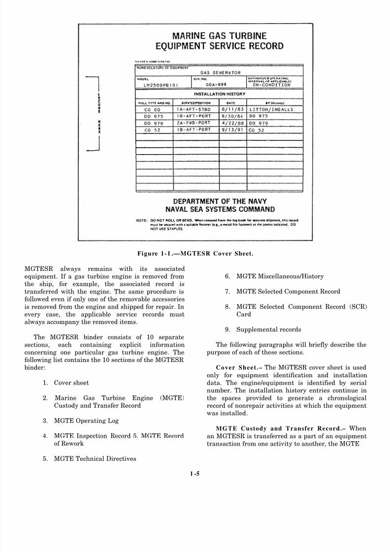
The cover page of an MGTESR is shown in figure 1-1.
The manufacturer of the equipment starts the
MGTESR. The MGTESR is later maintained by the
activity having custody of the equipment. The
1-4
8/14/2019 US Navy Course NAVEDTRA 14115 - Gas Turbine Systems Technician Mechanical) 2
http://slidepdf.com/reader/full/us-navy-course-navedtra-14115-gas-turbine-systems-technician-mechanical 19/349
Figure 1-1 .—MGTESR Cover Sheet.
MGTESR always remains with its associatedequipment. If a gas turbine engine is removed fromthe ship, for example, the associated record is
transferred with the engine. The same procedure isfollowed even if only one of the removable accessories
is removed from the engine and shipped for repair. Inevery case, the applicable service records mustalways accompany the removed items.
The MGTESR binder consists of 10 separate
sections, each containing explicit informationconcerning one particular gas turbine engine. Thefollowing list contains the 10 sections of the MGTESR
binder:
1. Cover sheet
2. Marine Gas Turbine Engine (MGTE)Custody and Transfer Record
3. MGTE Operating Log 4. MGTE Inspection Record 5. MGTE Record
of Rework
5. MGTE Technical Directives
6. MGTE Miscellaneous/History
7. MGTE Selected Component Record
8. MGTE Selected Component Record (SCR)Card
9. Supplemental records
The following paragraphs will briefly describe thepurpose of each of these sections.
Cover Sheet.– The MGTESR cover sheet is used
only for equipment identification and installation
data. The engine/equipment is identified by serialnumber. The installation history entries continue in
the spaces provided to generate a chronologicalrecord of nonrepair activities at which the equipmentwas installed.
MGTE Custody and Transfer Record.– When
an MGTESR is transferred as a part of an equipment
transaction from one activity to another, the MGTE
1 -5

8/14/2019 US Navy Course NAVEDTRA 14115 - Gas Turbine Systems Technician Mechanical) 2
http://slidepdf.com/reader/full/us-navy-course-navedtra-14115-gas-turbine-systems-technician-mechanical 20/349
Figure 1-2.—MGTE Custody and Transfer Record.
Figure 1-3.—MGTE Operating Log.
1-6

8/14/2019 US Navy Course NAVEDTRA 14115 - Gas Turbine Systems Technician Mechanical) 2
http://slidepdf.com/reader/full/us-navy-course-navedtra-14115-gas-turbine-systems-technician-mechanical 21/349
Fi gure 1-4.—MGTE Inspe ct ion Rec ord.
Custody and Transfer Record is completed before thetransfer. (See fig. 1-2.) This record shows who hascustody of the MGTESR and the engine or
equipment’s condition (complete/uncannibalized) atthe time of transfer. The commanding officer or the
person appointed signs this record.
MGTE Operating Log.– The MGTE Operating
Log shows the total operating time of the engine,starting from the time the engine was new. It alsoshows the time interval since the last depot repair or
rework was performed.
A sample of an MGTE Operating Log is shown infigure 1-3. Notice that the operating time and thenumber of starts must be entered on a daily, weekly,
or monthly basis. You should also note that an engine
start is defined as the engine’s successfully going
through the start cycle to idle. Motoring and hungstarts should not be entered in the NO. STARTScolumn of the log.
MGTE Inspection Record.– Accurate inspection
records are a primary requirement, and they prevent
the unnecessary reinspection by a new custodian
upon transfer of an equipment item. The MGTEInspection Record, shown in figure 1-4, provides forthe logging and authenticating of the performance ofall special and conditional inspections performed on
the equipment. You should note that the performanceof routine or periodic inspection requirements of the
Planned Maintenance System (PMS) are not recordedon this record.
1 -7

8/14/2019 US Navy Course NAVEDTRA 14115 - Gas Turbine Systems Technician Mechanical) 2
http://slidepdf.com/reader/full/us-navy-course-navedtra-14115-gas-turbine-systems-technician-mechanical 22/349
Figure 1-5.—MGTE Record of Rework.
Figure 1-6.—MGTE Technical Directives.
1-8

8/14/2019 US Navy Course NAVEDTRA 14115 - Gas Turbine Systems Technician Mechanical) 2
http://slidepdf.com/reader/full/us-navy-course-navedtra-14115-gas-turbine-systems-technician-mechanical 23/349
Figure 1-7 .—MGTE Miscel laneous / History.
MGTE Record of Rework.– The MGTE Record of
Rework, shown in figure 1-5, is a complete record of
all repair, reconditioning, conversion, change,modernization, or rework performed on the
equipment at a repair or rework facility.
MGTE Technical Directives.– The MGTE
Technical Directives sheet is a record of technicaldirectives (TDs) affecting the equipment andaccessories. (See fig. 1-6.) A separate form is used for
each type of TD, and all applicable directives arerecorded. Gas turbine TDs are issued as gas turbine
bulletins (GTBs) or gas turbine changes (GTCs). Allgas turbine TDs, including their revisions andamendments, should be recorded by number in this
section of the MGTESR.
MGTE Misce l laneo us/ History.– The
Miscellaneous/ History sheet, shown in figure 1-7, isused in the MGTESR to record pertinent information
for which no other place has been provided. Thisinformation includes significant details that might beof service to personnel or activities involved in later
diagnoses of problems with the equipment. Thesignificant details include special test data, abnormal
characteristics of the equipment, significant damageor repairs, and engine lay-up procedures.
MGTE Selected Component Record.– The
MGTE Selected Component Record, shown in
1 -9
8/14/2019 US Navy Course NAVEDTRA 14115 - Gas Turbine Systems Technician Mechanical) 2
http://slidepdf.com/reader/full/us-navy-course-navedtra-14115-gas-turbine-systems-technician-mechanical 24/349
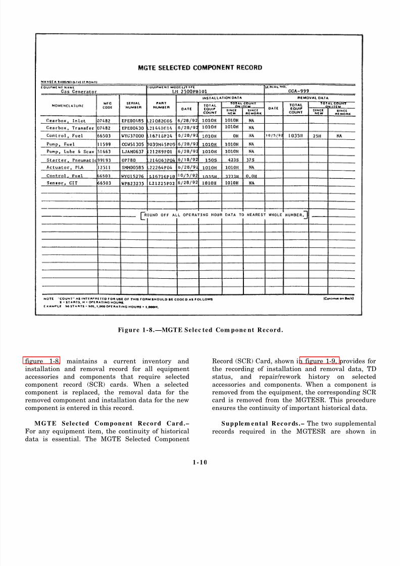
Fi gure 1-8.—MGTE Selec ted Com pone nt Record.
figure 1-8, maintains a current inventory andinstallation and removal record for all equipmentaccessories and components that require selected
component record (SCR) cards. When a selectedcomponent is replaced, the removal data for the
removed component and installation data for the newcomponent is entered in this record.
MGTE Selected Component Record Card.–
For any equipment item, the continuity of historical
data is essential. The MGTE Selected Component
Record (SCR) Card, shown in figure 1-9, provides for
the recording of installation and removal data, TDstatus, and repair/rework history on selected
accessories and components. When a component isremoved from the equipment, the corresponding SCRcard is removed from the MGTESR. This procedure
ensures the continuity of important historical data.
Supplem ental Records .– The two supplemental
records required in the MGTESR are shown in
1-10

8/14/2019 US Navy Course NAVEDTRA 14115 - Gas Turbine Systems Technician Mechanical) 2
http://slidepdf.com/reader/full/us-navy-course-navedtra-14115-gas-turbine-systems-technician-mechanical 25/349
Figure 1-9.—MGTE Selected Component Record Card.
1-11

8/14/2019 US Navy Course NAVEDTRA 14115 - Gas Turbine Systems Technician Mechanical) 2
http://slidepdf.com/reader/full/us-navy-course-navedtra-14115-gas-turbine-systems-technician-mechanical 26/349
Figure 1-10.—Supplemental Record.
1-12

8/14/2019 US Navy Course NAVEDTRA 14115 - Gas Turbine Systems Technician Mechanical) 2
http://slidepdf.com/reader/full/us-navy-course-navedtra-14115-gas-turbine-systems-technician-mechanical 27/349
Figure 1-11.—Diesel Engine Operating Record—All Ships.
figure 1-10. These records are the MGTE TurbineRotor Disc Assembly Service Record and the MGTE
Compressor Rotor Assembly Service Record. When aturbine rotor disc assembly is to be reworked, the
rework activity must ensure that data associatedwith each disc is properly recorded. The samerequirement is true if the compressor rotor assembly
is reworked. Although one record is required for eachturbine rotor disc or stage, only one record is required
for the complete compressor rotor assembly.
DIESEL ENGINE RECORDS.– As a GSM2 on
board an FFG-7 class ship, you can expect to review
diesel engine records. The repair and history recordsare primarily for the operating personnel of the ship.
They will prove valuable in making estimates of partsneeded and work lists for the next availability. A
system must be setup by which completely accurateand up-to-date records can be kept on all dieselengines.
The Diesel Engine Operating Record, shown infigure 1-11, is a daily record maintained for eachoperating diesel engine. For ships with more than one
diesel in the same machinery room, a separate recordsheet is maintained for each operating diesel engine.The watch supervisor enters the remarks and signs
the record for his or her watch. The engineer officerimmediately receives a report of any unusual
conditions noted in the record. The engineer officerthen receives the record for his or her approval.
REDUCTION GEAR RECORDS.– Maintaining a
log for the main reduction gear is extremely
important. This log should be kept in the engine roomand the readings must be taken and recorded atestablished intervals. A reduction gear log serves as a
guide in detecting unusual and inefficient operatingconditions. Temperatures, pressures, and thepresence of oil in the sight flow indicators are
important readings that should be included on thislog.
1-13

8/14/2019 US Navy Course NAVEDTRA 14115 - Gas Turbine Systems Technician Mechanical) 2
http://slidepdf.com/reader/full/us-navy-course-navedtra-14115-gas-turbine-systems-technician-mechanical 28/349
Fi gure 1-12 .—Com pres sor Operating Data Log S he et.
AIR COMPRESSOR RECORDS.– A typical air
compressor Operating Data Log Sheet is shown infigure 1-12. This log is kept by the operator who takes
and records readings at established intervals. Forextended operation, a data log sheet should be filled
out during every watch. A log is helpful not only fromthe operational and maintenance standpoints but alsoas a troubleshooting guide for detecting unusual and
inefficient operating conditions.
Depending on the ship’s air system demand, theactual operating time on each compressor of amulticompressor installation might differ. For each
compressor to provide the best service, the operatingtime should be equalized over each quarterly period.
Reviewing the entries on these logs and noting thehours recorded will allow the operators to change theoperating sequence of the units accordingly.
DISTILLING PLANT OPERATING RE-CORD.–
The Distilling Plant Operating Record is a dailyrecord of the operating ship’s evaporators and theirauxiliaries. Entries are made for each hour while the
distilling plant is operating. Different gas turbineships have many different types of distilling plants,
but all daily distilling plant operating records willrequire practically the same type of data entries. Thefollowing list includes the required information:
1. Temperature, pressure, vacuum, flow, chemicalanalysis, and density data from various points in the
distilling plant
2. Scaling record for each evaporator unit, includingthe date of the last scaling, the hours operated, andthe quantity of distilled water produced since the last
scaling to the day of the record and since the last
scaling to the end of the day record 3. Starting, stopping, and total operating time ofeach evaporator and various auxiliary machinery
parts, such as air ejector and pumps
4. Remarks about the operation and maintenance ofthe distilling plant for each watch of the day
5. You must make accurate entries in the DistillingPlant Operating Record. Accurate entries will help
predict trouble. If abnormal operating conditions
should suddenly develop, the entries in the recordshould aid in locating the sources of trouble.
REFRIGERATION/ AIR-CONDITIONING
RECORDS.– Your department will use the daily
operating log for refrigeration equipment or air-conditioning plants to maintain a record of operating
conditions. The log, shown in figure 1-13, is a guidefor the continued analysis of operating conditions andoperating results found in the equipment. Notice that
1-14

8/14/2019 US Navy Course NAVEDTRA 14115 - Gas Turbine Systems Technician Mechanical) 2
http://slidepdf.com/reader/full/us-navy-course-navedtra-14115-gas-turbine-systems-technician-mechanical 29/349
Figure 1-13.—Refrigeration/Air-Conditioning Equipment Operating Record.
1-15

8/14/2019 US Navy Course NAVEDTRA 14115 - Gas Turbine Systems Technician Mechanical) 2
http://slidepdf.com/reader/full/us-navy-course-navedtra-14115-gas-turbine-systems-technician-mechanical 30/349
data entries are made on both sides of the form. (See
views A and B.)
The information in this log provides a method for
engineering personnel to determine when and what
corrective measures are necessary when a plant is not
operating properly. Data taken at various points in the
system are compared with corresponding data taken
during normal plant operation. The corresponding data
must be taken under the same heat load and circulating
water temperature conditions.
Daily Reports and Records
Maintenance of daily fuel, lubricating oil, and water
accounts is essential to the efficient operation of the
engineering department. The TYCOMs prescribe the
forms and procedures necessary to account for fresh
water and fuel. These reports and records inform the
engineer officer of the status of the ship’s liquid load and
form the basis of several important reports, which are
sent to higher authority. The most important of these
reports is the report of the amount of burnable fuel on
hand.
FUEL AND WATER REPORT.– The Fuel and
Water Report is a daily report of the fuel and water status
prepared to reflect these conditions at 0000 hours. The
commanding officer receives this report daily. The
report contains data, such as total fuel and total lube oil
on board and the amount of potable water and reserve
feedwater on board. The Fuel and Water Report also
includes the previous day’s feedwater and potable water
consumption figures and the results of the water tests.
The officer of the deck (OOD) receives the original copy
in time for submission to the commanding officer orcommand duty officer with the 1200 reports. The OOD
retains the copy.
DAILY WATER ACCOUNT.– Some gas turbine
ships maintain a Daily Water Account. The Daily Water
Account is a daily record of the feedwater for the boilers
and the potable fresh water in the potable water tanks.
The data are recorded on the form by the oil king and
checked for accuracy by his or her leading petty officer.
The division officer also checks the form. When
completed and checked, the record is submitted to the
engineer officer for his or her approval and signature.
DUTIES, RESPONSIBILITIES, AND
REQUIREMENTS
From reading this chapter, you should recognize
that there are many logs and records engineering
department personnel are required to maintain. The
responsibilities only begin with the accurate recording
of data for the machinery and equipment. The entries
must be made not only in the proper logs or records but
also in the appropriate sections of these logs or records.
One of the most important responsibilities will be
verifying the accuracy of these entries. The importance
of this responsibility should not be underestimated.
Engineering personnel will base their determinations in
regard to the condition of the equipment on the
information contained in these logs and records.
Verification Procedures
As you advance in the GSM rating, you will be
required to verify many of the engineering logs and
records. In fact, you may be required to review many
logs and records on a daily basis. In reviewing logs and
records, there are certain details you should look for and
take note of. Although each situation or type of log or
record may have its own set of required procedures, the
following list contains a few of the most important basic
details for which you should check:
All readings and entries must be legible.
All entries must be placed in the proper location
in each log.
Out-of-limits entries must be circled in RED and
explained in the REMARKS section of the logs.
All required initials and signatures must be
present.
All logs and records must be free of erasures.
All required logs and records must be present. As stated earlier, the verification process is one of
the most important responsibilities you will face as you
advance in the GSM rating. Another important part of
your increasing administrative duties will involve
learning the correct disposal procedures for the records
your department will no longer need to keep.
Disposal Procedures
Before destroying any engineering department
records, study the Disposal of Navy and Marine Corps
Records, USN and USNS Vessels, SECNAVINSTP5212.5 (revised). This publication provides the official
procedures for disposing of records. For each
department aboard your ship, these instructions list the
permanent records that must be kept. The instructions
also list the temporary records that may be disposed of
according to schedule.
1-16
8/14/2019 US Navy Course NAVEDTRA 14115 - Gas Turbine Systems Technician Mechanical) 2
http://slidepdf.com/reader/full/us-navy-course-navedtra-14115-gas-turbine-systems-technician-mechanical 31/349
At regular intervals, such as each quarter, records
that are more than 3 years old are usually destroyed.
When a ship that is less than 3 years old is
decommissioned, the current books are retained on
board. If a ship is scrapped, the current books are sent
to the nearest naval records management center. All
reports sent to, and received from, NAVSEA or another
superior command may be destroyed when they are 2
years old, if they are no longer required.
To control the volume of paper work, reports shouldbe kept on board only if they are
1. required,
2. serve a specific purpose, or
3. provide repair personnel with information not
found in other available publications or
manuals.
As you assume more extensive administrative
responsibilities, you will be required to become
increasingly aware of the retention, disposal, and
maintenance procedures required for your department.
FILES AND TICKLER SYSTEMS
As a second class GSM, you will be required to learn
how to maintain correspondence files, messages, and
tickler systems. You will need to determine the
requirements of your division. You should know how to
set up the files, what to file, and how to use the files to
gather necessary information. You will also need to
make sure that information your division develops is
sent to higher authority in the proper form of reports or
packages.
The accuracy of a filing system and the ease in
retrieving information is extremely important if the
system is to be effective. Administration of the
engineering department requires easy access to previous
information either received or sent out. Efficiently
managed files contribute directly to the overall
effectiveness of the engineering department.
Each month the engineering department should
close out the files, logs, and records of the previous
month. This means a new set is needed for each new
month. When starting up a new month’s logs, records,
and files, always take a look at last month’s logs,records, and files. Determine which logs, records, or
files were bulky and which contained only a few pieces
of paper. Use this information to set up your new folders.
Some files may have to be broken down to make them
quicker to find. Some files may be combined to save
space.
One final decision to make when setting up files is
how to keep your logs, records, and files centralized.
This step will help you prevent a backlog of requests for
information or delays when you must produce a
particular log or record.
Efficiency can be maintained by a thorough training
program for all engineering personnel involved in log
keeping. If all personnel are familiar with the filing
system, they will place the logs and records in the proper
location. As a GSM2, you will likely be assigned to maintain
a variety of tiles. Most routine tiles will involve those
for correspondence, messages, or tickler systems. Each
of these categories is briefly described in the following
sections.
Correspondence
Correspondence inc ludes a l l written
material—publications, messages, memoranda, and so
on—sent to and from a command. You must read and
understand these types of correspondence. The system
used to file your division’s correspondence should be
one that all personnel can use.
Messages
Messages are the quickest form of written
communication in the Navy. This is because our
telecommunications system is capable of getting
time-sensitive or critical information to addressees
rapidly for effective use of information. There are
several methods used to file messages. Your division
may file messages according to date-time group (DTG),
precedence category, or subject matter. You should learn
your division’s message filing system to help you locate
critical information.
Tickler Systems
A tickler system consists of record cards, usually
organized in a standard desk-top box, in chronologicalor alphabetical order. This system makes handling
recurring reports simpler. The reports tickler file
requires daily attention if it is to be an effective tool. You
must keep it and the information it contains up to date,
and you must inform responsible personnel of currentrequirements for reports.
1-17

8/14/2019 US Navy Course NAVEDTRA 14115 - Gas Turbine Systems Technician Mechanical) 2
http://slidepdf.com/reader/full/us-navy-course-navedtra-14115-gas-turbine-systems-technician-mechanical 32/349
Figure 1-14.—PMS Feedback Report.
PMS FEEDBACK FORMS
The PMS Feedback Report (FBR) is a form shipsuse to notify the Naval Sea Support Center(NAVSEACEN) or the TYCOM of matters related to
PMS. The FBR is a five-part form composed of anoriginal and four copies. A completed FBR is shown
in figure 1-14. The front side, shown in view A, isused for data describing a specific PMS problem. Thereverse side of the last copy, shown in view B,
provides instructions for preparing and submittingthe form. As you advance in the GSM rating, you will
prepare, submit, and review several FBRs. Thefollowing information will help you understand yourresponsibilities concerning the FBR.
Preparation Procedures
When a PMS-related problem occurs, you should
try to correct the problem, especially if it presents asafety hazard. The PMS FBR is your vehicle for thesolution to the problem. To prevent delays in
correcting the problem, however, you should makecertain to complete and submit the form correctly
according to the instructions on the back.
Once you identify a PMS problem, you shouldimmediately start entering the documentation on theFBR. You can either use a typewriter or neatly
handprint your entries. Remember to insert yourship’s name and hull number. Leave the date and
serial number blank. The 3-M coordinator will insertthe information in these two blocks.
1-18

8/14/2019 US Navy Course NAVEDTRA 14115 - Gas Turbine Systems Technician Mechanical) 2
http://slidepdf.com/reader/full/us-navy-course-navedtra-14115-gas-turbine-systems-technician-mechanical 33/349
Next, you must determine what category yourparticular problem is assigned to. There are two
categories of FBRs—category A and category B.These categories are defined as follows:
• Category A–This category is nontechnical
in nature and meets PMS needs that do notrequire technical review. The FBRsassigned this category pertain to the need
for replacement of missing or mutilatedmaintenance index pages (MIPs) or
maintenance requirement cards (MRCs).
• Category B–This category is technical innature. It is submitted by the ship’s 3-M
coordinator to the applicable TYCOM.FBRs assigned this category pertain to thenotification of a shift in maintenance
responsibilities from one work center toanother. These FBRs also pertain to
TYCOM assistance in the clarification of 3-
M instructions. This category also appliesto technical discrepancies inhibiting PMS
performance. These discrepancies can existin documentation, equipment design,
maintenance, reliability, or safetyprocedures. The discrepancies can beoperational deficiencies in PMS support
(parts, tools, and test equipment), as well.
NOTE
When the reason for submission of a PMS FBRinvolves safety of personnel, or potential for
damage to equipments and relates to thetechnical requirements of PMS, the FBR isconsidered URGENT. Urgent FBRs must be
sent by naval message to both NAVESEACENswith information copies to the cognizant
SYSCOM/BUMED/NAVSAFECEN/TYCOM.
Your next step is to fill in the equipmentidentification section. This information consists of
system, subsystem, or component, allowance parts
list (APL), MIP number, and MRC control number.Under the DESCRIPTION OF PROBLEM section,check the proper block under either CATEGORY A orCATEGORY B. In the REMARKS section, provide a
brief description of the problem or requirement.Remember to include sufficient information to
describe the problem. Next, insert the work centercode and sign the FBR. The FBR will then be routedthrough your chain of command for review and
approval.
Fi gure 1 -15 .—Standard Equipment Guide List.
Review Proc edures
Before sending your FBR through the chain ocommand, you should review the form forcompleteness and accuracy. One section you shouldclosely scrutinize is the equipment identification
section. Errors in this section will cause delays inprocessing your FBR. Provide as much information as
you can. Make certain you use the correct APLnumber for hull, mechanical, or electrical equipment.Read the comments in the REMARKS section. Make
certain the comments are legible and complete. Onhandwritten FBRs, be sure each copy is clear and
legible. Observation of these simple guidelines willhelp you maintain your equipment in a high state of
readiness.
EQUIPMENT GUIDE LIST
The Equipment Guide List (EGL) is a 5" x 8" card
(fig. 1-15) that is used with a controlling MRC. Whenthe MRC applies to the same type of items (motors,controllers, valves, test equipment, and so forth), use
an EGL card. Each ship prepares its own EGLsStandard EGL forms are available from the Navy
supply system.
When determining the number of items to include
on an EGL, you should consider the skill level of theassigned maintenance person and the time that will
be required to complete the maintenance on eachitem. Remember, each page of an EGL should containno more than a single day’s work. If more than one
day is required, prepare a separate EGL page foreach day, and number the pages consecutively.
1-19

8/14/2019 US Navy Course NAVEDTRA 14115 - Gas Turbine Systems Technician Mechanical) 2
http://slidepdf.com/reader/full/us-navy-course-navedtra-14115-gas-turbine-systems-technician-mechanical 34/349
Fi gure 1 -16 .—Simplified all-purpose material
symbol .
DIAGRAMS AND EQUIPMENT
LAYOUTS
Drawings and equipment layouts are the universal
language used by engineers and technicians. They conveyall the necessary information to the individual who will
maintain, operate, and repair the equipment andmachinery.
To complete assigned tasks, a GSM must be able toread and understand various types of machine
(equipment) and piping drawings and system diagrams.
To read any machine or piping drawings or systemdiagrams, you must be familiar with the common terms
and standard symbols used for these drawings anddiagrams.
COMMON TERMS AND SYMBOLS
GSMs use drawings and diagrams in the installation,maintenance, and repair of shipboard equipment and
systems. The following sections will provide a brief description of these common terms and symbols. For more
detailed information, refer to Blueprint Reading and
Sketching, NAVEDTRA 10077-F1.
Tolerances
Tolerances represent the total amount by which aspecific dimension may vary. Tolerances may be shown ondrawings by several different methods. The unilateral
method is used when variations from the design size ispermissible in one direction only. In the bilateral method,
a dimension figure will show the plus or minus variationthat is acceptable. In the limit dimensioning method, themaximum and minimum measurements are shown.
Fillets an d Rounds
Fillets are concave metal corner (inside) surfaces. In
casting, a fillet normally increases the strength of a metalcorner. A rounded corner cools more evenly than a sharpcorner, thereby reducing the chance of a break. Rounds or
radii are edges or outside corners that are rounded toprevent chipping and to avoid sharp edges.
Fi gure 1-17 .—Isom etric drawing o f a clevis .
Fi gure 1-18 .—Oblique and orthographic projec tio
Slots and Sl ides
Slots and slides are for the mating of two specia
shaped pieces of material. Though secured together, pieces can still move or slide.
Casting
Casting refers to the process of making an object pouring molten metal into a mold (normally of sand) of t
desired shape and allowing it to cool.
Forging
Forging is a process of shaping metal while it is hot
pliable. The hammering or forging process is done eithmanually (blacksmith) or by machine.
Ke y
A key is a small wedge or rectangular piece of meinserted in a slot or groove between a shaft and a hub
prevent slippage.
Keyseat
A keyseat is a slot or groove into which the key fits.
Keyway
A keyway is the slot or groove within a cylindrical tuor pipe into which a key fitted into a keyseat will slide.
1-20

8/14/2019 US Navy Course NAVEDTRA 14115 - Gas Turbine Systems Technician Mechanical) 2
http://slidepdf.com/reader/full/us-navy-course-navedtra-14115-gas-turbine-systems-technician-mechanical 35/349
Figure 1 .19 .—Detail drawing of a base pivot.
Tempering
Tempering is the method for hardening steel by
heating it and then suddenly cooling it by immersionin oil, water, or another coolant.
All-Purpos e Mate rial Sym bol
An all-purpose material symbol is shown in figure1-16. In drawings, this symbol represents materials of all types.
MACHINE DRAWINGS AND SYSTEM
DIAGRAMS
Once you grasp a good understanding of the terms
and symbols, drawings and diagrams will become lesscomplex and easier to use. This section will provide
descriptions and illustrations of the most commonlyused drawings and diagrams.
Isom etric Drawings
An example of an isometric drawing is shown infigure 1-17. An isometric drawing is a set of three or
more views of an object that appears rotated. This
gives the appearance of viewing the object from onecorner. All lines are shown in their true length, but
not all right angles are shown as such.
Oblique Drawings
A sample of an oblique drawing is shown in figure
1-18. Notice that an oblique drawing shows an objectin three dimensions. It is a projection of an object’s
front and top surfaces, which shows the viewer thelength, width, and height.
Orth ographic Drawings
Figure 1-18 is also an example of an orthographicdrawing. It is a drawing that provides a two-
dimensional view; that is, it shows only the object’sheight and width.
Detail Drawings
Refer to the detail drawing shown in figure 1-19. Adetail drawing is a print illustrating a singlecomponent or part. It shows a complete and exact
description of the shape and dimensions of the partand how it is made (its construction).
1-21

8/14/2019 US Navy Course NAVEDTRA 14115 - Gas Turbine Systems Technician Mechanical) 2
http://slidepdf.com/reader/full/us-navy-course-navedtra-14115-gas-turbine-systems-technician-mechanical 36/349
Fi gure 1-20 .—Single-line diagram for fuel oi l service s yst em .
Single -Line Diagram
Figure 1-20 is an example of a single-line diagram. A single-line diagram uses lines and graphic symbols
to simplify a complex circuit or system. Contained inthe Engineering Operating Procedures (EOP) section
of EOSS, these types of diagrams are the ones thatyou will use everyday. They will aid you as you aremaintaining, repairing, or aligning shipboard
systems.
EQUIPMENT LAYOUTS
Engineering personnel use equipment layouts asaids to locate various pieces of equipment throughouta machinery space. Equipment layouts are extremely
helpful to newly reporting personnel who are notfamiliar with the engineering spaces. The mainpurpose of an equipment layout is to show the
physical relationship of the equipment to its locationin a space. Some layouts are more detailed than
others, but the primary purpose is the same. While
some equipment layouts may show only the physicallocation of machinery, others will show the pipingthat connects various pieces of equipment together.
Figures 1-20 and 1-21 are examples of equipment
layouts. On a gas turbine-powered ship, you willprimarily find equipment layouts in the EOP andpropulsion plant manuals (PPMs). The equipment
layouts in the EOP are used mainly for training newpersonnel. The use of an equipment layout for system
tracing depends upon the amount of detail includedin the equipment layout.
SUMMARY
This chapter has provided you with a variety ofinformation to help you become a more efficient and
effective GS.
This chapter described the Navy’s QA program
and how you, a work center supervisor, will become
1-22

8/14/2019 US Navy Course NAVEDTRA 14115 - Gas Turbine Systems Technician Mechanical) 2
http://slidepdf.com/reader/full/us-navy-course-navedtra-14115-gas-turbine-systems-technician-mechanical 37/349
Figure 1-21.—Engine-room equipment layout.
involved in this program. This chapter also describedthe engineering administration system. The
preparation procedures for various operating logs andrecords were discussed along with general guidelines
for maintaining files, correspondence, and messages.
This chapter also described preparation andsubmission procedures for PMS FBRs and the various
uses of diagrams and layouts you will encounter as aGSM.
1-23

8/14/2019 US Navy Course NAVEDTRA 14115 - Gas Turbine Systems Technician Mechanical) 2
http://slidepdf.com/reader/full/us-navy-course-navedtra-14115-gas-turbine-systems-technician-mechanical 38/349
8/14/2019 US Navy Course NAVEDTRA 14115 - Gas Turbine Systems Technician Mechanical) 2
http://slidepdf.com/reader/full/us-navy-course-navedtra-14115-gas-turbine-systems-technician-mechanical 39/349
CHAPTER 2
OIL LABORATORY PROCEDURES AND ADMINISTRATION
In your career as a GSM, you may be assigned to
your ship’s oil laboratory. If you have already been
assigned to the oil lab, you are likely aware of thesignificance of your role as a middle manager. In the
oil lab, your most important job will be to maintain
the quality of your ship’s fuels, oils, and water
supplies. The efficient operation of your ship’s
engineering equipment and systems directly depends
on the quality of these products.
This chapter will discuss the safety precautions
you will need to know whenever you are handling,
testing, stowing, or disposing of hazardous fluids,
chemicals and materials. It will also discuss the proper
way to perform certain sampling and testing
procedures, record the results, and review and
maintain the logs related to the operations of the
engineering plant and the oil laboratory. After
studying the information in this chapter, you should
have a good understanding of the inner workings of
the oil laboratory and the important role it plays in the
everyday operations of your ship.
SAFETY PRECAUTIONS
No matter where you are assigned, the
responsibility for safety goes with you. As a GSM,you are already familiar with many of the
job-related safety hazards you can face every day
and the safety precautions you must observe.
Good safety habits are especially important
when you are working in the oil laboratory. On a
day to day basis, you may be required to handle,
test, transfer, and dispose of the most hazardous
and toxic liquids and materials on board your ship.
No matter what you already know or where you are
assigned, it is vitally important for you to
understand and adopt good safety habits in your
daily work routines and responsibilities.
The following sections will discuss some of the
safety precautions you should take. These
precautions are specifically related to the materials
and equipment you will handle in your routine
responsibilities in the oil lab.
HANDLING AND MONITORING
HAZARDOUS MATERIALS
Fire and other potential disasters can occur
whenever you must handle, test, transfer, stow, or
dispose of hazardous solutions and materials. In the
following sections, we will explain the specific safety
precautions you must take whenever you are handling
or monitoring the hazardous solutions and materials you
will have to work with in the oil lab. Because they are
the most dangerous materials on your ship, we will
discuss petroleum products first.
Petroleum products
As you have been frequently reminded, a shipboard
fire is the most dangerous mishap you and your
shipmates can experience. You should consider all
petroleum products to be potential fire hazards.
In your everyday work in the oil lab, you may be
required to handle or monitor petroleum products. Most
petroleum products fall into two basic categories: fuels
and oils. Because they are the most dangerous petroleum
products carried on your ship, we will discuss fuels first.
FUELS.– Fuels are the most dangerous products
aboard ship not only because they ignite easily but also
because your ship must stow them in such large
quantities. To minimize these hazards, the fuels on your
ship must meet applicable safety precautions for
flammables. While assigned to the oil lab, you must be
aware of these safety precautions for characteristics
such as flash points, vapors, spontaneous ignition
temperatures, wicking, and mist formation. In the
following paragraphs, we will explain the required
safety standards for each of these characteristics.
Flash Points.– The flash point of a fuel is the lowest
temperature at which the fuel will give off sufficient vapor to form a flammable mixture with the air above
the surface of the fuel in its liquid state. In other words,
to be able to form a flammable vapor-air mixture,
evaporation of the fuel must take place at or above its
flash point. The required minimum flash point for naval
distillates (F-76) and JP-5 (F-44) is 140°F (60°C).
2-1

8/14/2019 US Navy Course NAVEDTRA 14115 - Gas Turbine Systems Technician Mechanical) 2
http://slidepdf.com/reader/full/us-navy-course-navedtra-14115-gas-turbine-systems-technician-mechanical 40/349
Fuel Vapors.– Fuel vapors form when a liquid fuel
undergoes the process of evaporation. When F-76 and
JP-5 are mixed with air in certain proportions,
flammable vapors result.
Fuel vapors are heavier than air. This is important
for you to understand because fuel vapors will tend to
collect in the lowest levels of your ship’s compartments,
such as the bilges. Fuel vapors can travel rapidly from
compartment to compartment through existing
openings. You may not be aware of these vapors untilthey ignite by an unsuspected source. Some sources that
can cause fuel vapors to ignite are open flames, electric
sparks, sparks produced from striking metals, heat from
exposed hot piping, and smoking.
Spontaneous Ignition Temperatures.– The
spontaneous ignition temperature (SIT) is also called the
autoignition or autogenous ignition temperature (AIT).
The SIT or AIT is the minimum temperature at which a
fuel or fuel blend will ignite spontaneously in air without
the aid of a spark or flame. The importance of the SIT
or AIT is that it identifies the lower limit of fire hazard
whenever you are handling fuels near hot surfaces. In
other words, to conform with prescribed military
standards and safety guidelines, you must not handle
fuels in areas in which temperatures exceed the SIT or
MT.
For both F-76 and JP-5 fuels, the SIT values can be
as low as 450°F (232.2°C). For this reason, you should
consider these two fuels to be equally hazardous.
General specifications for the building of naval ships
require that any surface that might exceed a temperature
of 400°F (204.4°C) must be suitably insulated so that
temperatures of the exposed surface will not exceed thiscritical level.
The procedure by which the SIT or AIT rating of a
fuel is determined is very complex. To do your part in
preventing fire hazards, you must respect and accept the
established laboratory SIT values. In your oil lab duties,
always consider the SIT value of any fuel you must
handle and try to take every precaution to prevent the
fuel from dripping onto a hot surface.
Wicking and Mist Formation.– Normally, fuels do
not form flammable vapor-air mixtures at temperatures
below their flash points. There are two exceptions to this
rule: (1) wicking and (2) mist formation. Both of these
conditions provide the means by which fuels can ignite
even at temperatures below their flash points.
Wicking occurs when a fuel is drawn onto an
absorbent solid material that can be ignited locally.
When a flame is applied to a wick, a hot spot forms on
the wick. The hot spot will continue to give off sufficient
vapors to sustain the flame.
Candles and kerosene lamps are good examples of
wicking. Rags soaked with fuels also make excellent
wicks. For this reason, you should always consider
fuel-soaked rags to be potential fire hazards.
Fuel mists can form when a rupture or small leak
occurs in a pressurized fuel line. Fuel mist formation can
also be caused by fuel vapor condensation that results
from sudden cooling. Mists from fuel droplets mix with
air, forming a flammable mixture. When exposed to an
ignition source, these mists can ignite. Once ignited, the
fuel mists will continue to bum because the fuel spray
droplets entering the flame zone will continue to
vaporize as long as they are exposed to the heat of the
flame.
It is vitally important for you to understand the fuel
characteristics we have just described and the prescribed
safety guidelines and precautions you must use
whenever you come in contact with these products.
Remember, these characteristics are always presentwherever fuels are handled, tested, stowed, transferred,
or used aboard ship. They will always be dangerous
sources of potential fire hazards.
OILS.– Even though oils have a much higher flash
point than fuels, they are still dangerous if they are not
properly handled. The potential for fire always exists,
Like fuels, oils operate in some systems under high
pressure. This is why strict attention must be paid to
system integrity (prevention and control of leaks). The
policy of no leaks in any system carrying flammable
liquids is a good one. If oil should be forced out of a
system in the form of a fine mist, the results could be
disastrous.
Fire hazards are not the only danger associated with
petroleum products. They can also be harmful to
personnel by irritating the skin and eyes. Aboard ship,
fuel and oil products are handled daily. To most people,
the vapors from these products are irritating. To some
people, physical contact with these products can cause
severe skin disorders. This is why you must use
protective clothing, such as rubber gloves, a face shield,
and an apron whenever you handle these products.
Although the oil used in the gas turbines is not a
petroleum-based product, you need to be aware of
certain safety precautions. This oil is an synthetic
ester-based product that can cause dermatitis after
prolonged contact with the skin. If you come into contact
with this oil, wash your skin thoroughly and remove any
saturated clothing immediately.
2-2

8/14/2019 US Navy Course NAVEDTRA 14115 - Gas Turbine Systems Technician Mechanical) 2
http://slidepdf.com/reader/full/us-navy-course-navedtra-14115-gas-turbine-systems-technician-mechanical 41/349
Chemicals
Sampling and testing can be dangerous if you do not
follow the procedures carefully, if your equipment is
faulty, or if you carelessly handle or stow the testing
chemicals. In the oil lab, you will use specific chemicals
and chemical solutions for testing fuel, oil, and water
samples. In the next sections, we will identify these
chemicals and explain their associated safety
precautions. Material safety data sheets (MSDSs) are
available for all hazardous materials used by the Navy.
You should review the MSDSs for each chemical before
use. To be able to perform your fuel, oil, and water
testing procedures correctly, you must know how to use
these chemicals safely.
FUEL AND OIL TESTING.– There are only two
chemicals you will normally use for fuel and oil testing.
These chemicals are dry-cleaning solvent, better known
as P-D-680 type II, and absolute methanol. You will use
very small quantities of these chemicals in the oil lab.
Since both chemicals are flammable, bulk quantities
should be stowed in a flammable liquid store room.
WARNING
Take extra care when you are handling absolute
methanol. It is irritating to the skin, respiratory
tract, and eyes. It is moderately toxic by skin
absorption and highly toxic to the central
nervous system and optic nerve by ingestion.
Always use absolute methanol in a
well-ventilated area to avoid the accumulation
of vapors.
WATER TREATMENT CHEMICALS.–
Trisodium phosphate (TSP) and disodium phosphate
(DSP) are the only two treatment chemicals authorized
for use in waste heat boilers. You and all other oil lab
personnel should take care when either one of these
chemicals is used. In its concentrated form, TSP will
cause burns to the skin, eyes, and body tissues. If you
get TSPor its solution on your skin or in your eyes, flush
the affected area with cold, potable water for 15 minutes
and obtain medical attention.
For both TSP and DSP, the safety dispensing bottlemust be clearly marked and used for these boiler
treatment chemicals only. The type of dispensing bottle
used for both TSP and DSP is made from linear
polyethylene, a material that has a maximum use
temperature of 176°F (80°C). As they dissolve, both
TSP and DSP will generate heat. Do not use hot water
to dissolve these chemicals in their dispensing bottles.
The heat of the solution may exceed the maximum safe
dispensing temperature.
When mixing TSP with feedwater, you can either
add the TSP to the water or add the water to the TSP
without difficulty. When you are using large quantities
of DSP, however, you should add the DSP to the water
because DSP tends to cake when water is poured over
it.
Another water treatment chemical you may have to
handle is Nalcool 2000. This corrosion and rust inhibitor
is used in the jacket water systems of SSDGs, and it is
very hazardous.
Nalcool 2000 is hazardous because it contains
strong alkalies. Do not mix alkalies directly with acids
because the heat generated may cause the chemicals to
spatter. If alkalies come into contact with your skin,
flush the affected area with cold, potable water until the
slippery feeling disappears. If the burning or itching
sensation persists, seek medical attention. If alkalies
come into contact with your eyes, flush with cold,
potable water for 15 minutes at an eyewash station andseek immediate medical attention.
WATER TEST CHEMICALS.– During feedwater
and boiler water testing, you will come in contact with
several chemicals that require special handling and
disposal. If they are not properly handled, these
chemicals are hazardous both to personnel and to the
environment.
Most of these chemicals come in concentrated form
(stock solutions) and contain either caustic soda, nitric
acid, or mercuric nitrate. These chemicals can cause
burns to the skin and eyes and can be fatal if they areingested. To protect yourself, always wear goggles or a
face shield and either plastic or rubber gloves whenever
you are handling these solutions.
Now that we have discussed some of the potential
hazards you should be aware of when you are handling
or stowing the materials and solutions you will be using
or testing in the oil lab, let’s talk about the methods you
should use to dispose of these and other hazardous
products safely.
Hazardous Wastes
The discharge of oils or oily wastes into our aquatic
environment is a serious worldwide pollution concern.
These discharges (effluents) can cause significant and
long-lasting effects on marine life and the quality of
shoreside beaches. Oily discharges can also be a
potential hazard for fires and explosions. Because of
2-3

8/14/2019 US Navy Course NAVEDTRA 14115 - Gas Turbine Systems Technician Mechanical) 2
http://slidepdf.com/reader/full/us-navy-course-navedtra-14115-gas-turbine-systems-technician-mechanical 42/349
these concerns, U.S. Navy vessels must comply with
existing federal, state, local, national, and international
laws.
LAWS.– U.S. Public Law 96-478, Act to Prevent
Pollution from Ships, replaced the Oil Pollution Control
Act and implements the International Convention for the
Prevention of Pollution from Ships and the Clean Water
Act. Without impairing DOD operational capabilities,
U.S. Navy ships must comply with the following basic
standards of these laws and with the applicable Statusof Forces Agreement (SOFA) and OPNAVINST
5090.1A:
1. If operating in navigable waters of the United
States or within 50 nm from the U.S. coastline, your ship
is prohibited from discharging oil in quantities that will
cause a sheen or discoloration on the surface of the water
or deposits of sludge or emulsion beneath the surface or
on the adjoining shorelines. This means that all oily
discharges must be less than 10 ppm of effluent within
12 nm of shore and less than 100 ppm beyond the 12 nm
limit. Basically, this means your ship is prohibited from
directly discharging any oily bilge water at sea beforeprocessing it through an effective oil-water separator
(OWS).
2. If your ship is operating in coastal waters or
territorial seas up to 12 nm from the shoreline of a
foreign country, you must abide by the oily waste
discharge regulations of the applicable SOFA. In the
Mediterranean Sea, for example, your ship is restricted
to an effluent discharge rate of less than 15 ppm. If no
SOFA exists, your ship must operate according to the
standards of the host country’s military forces until a
satisfactory agreement with the host country can be
reached. Unless otherwise provided by a SOFA, U.S.
Navy vessels operating temporarily within a foreign
jurisdiction are subject to that country’s standards to the
extent specified by the clearance for a visit. If no
standards exist, your ship is prohibited from discharging
unprocessed oily wastes within 50 nm from land. Ships
that are not equipped with OWS units must retain all oily
wastes for proper disposal at a shore reception facility.
EQUIPMENT.– Because of the severity of the oil
pollution problem, the Navy is giving high-level
attention to the prevention of oily discharges from its
ships and crafts. Special equipment for monitoring andcontrolling shipboard effluents is currently being
installed throughout the fleet. To operate this equipment
effectively and comply with the laws and regulations,
consult OPNAVINST 5090.1A, Environmental and
Natural Resources Protection Manual, and Naval Ships’
Techical Manual (NSTM), chapter 593, “Pollution
Control.” As a GSM, you should be aware of the
following oil pollution abatement equipment/systems
that are scheduled for installation on U.S. Navy vessels:
1. Oil-water separators, oil content monitors, oily
waste holding tanks, and waste/used oil tanks that will
allow the ship to separate and collect shipboard waste
oil and to process oily wastes before discharging them
2. Bilge pumps (oily waste transfer pumps), piping
risers, and weather-deck connections that will allow safe
and convenient ship-to-shore transfer of oily wastes
3. Two and one-half inch cam-lock discharge
connections (MS27023-14) for oily waste discharge that
will allow for rapid connect/disconnect functions with
shoreside offloading hoses
4. Oily waste discharge adapters to accommodate
hoses with international-standard flanges when Navy
vessels visit foreign and non-Navy ports
5. Mechanical seals on shipboard pumps to
minimize the quantity of oily waste water collected in
the bilges
6. Improved tank level indicators to reduce
overboard spills during fueling and oily waste handling
and transfer operations
7. Contaminated fuel settling tanks to receive and
assist reclamation of fuel tank strippings which might
otherwise be discharged overboard
PROCEDURES.– For detailed procedural
instructions concerning shipboard oil pollution
abatement, you should consult NSTM, chapter 593,
“Pollution Control.” In the following sections, we will
discuss some of the highlights of these procedures and
other important information that you, as a GSM, should
be aware of when your ship must dispose of bilge water
and oily wastes, waste/used oils, and waste water test
chemicals.
Bilge Water and Oily Wastes.– You should be
aware of the procedures your ship will need to use for
the careful disposal of bilge water and oily wastes. As a
GSM in the oil lab, you can use the information in the
following list as a guideline.
1. Your ship must reduce oil contamination of itsbilge water to a minimum. Use of carefully maintained
mechanical seals in oil and water pumps and the proper
segregation of oily and nonoily waste water will help
your ship reduce generation of oily wastes. Your ship’s
efforts to segregate bilge water from oil are important
steps in pollution control.
2-4

8/14/2019 US Navy Course NAVEDTRA 14115 - Gas Turbine Systems Technician Mechanical) 2
http://slidepdf.com/reader/full/us-navy-course-navedtra-14115-gas-turbine-systems-technician-mechanical 43/349
2. Your ship should minimize use of any bilge
cleaners or chemical agents, such as detergents and
surfactants, that will promote chemical emulsion. This
step will enable the OWS units to work more effectively.
3. In port, your ship should off-load oily wastes to
a shore receiving facility. The use of shoreside donuts
(oil disposal rafts) is being phased out. Ships will be
charged an analysis fee for a laboratory analysis of
contaminated bilge water.
4. In port, your ship can use any of the following
methods to dispose of oily bilge water:
a. Oil-water separator (OWS) system–Your
ship should use its OWS system unless state standards
or local port authorities prohibit its use. This is one of
the most important steps in pollution control.
b. Oil-ship waste offload barges (O-SWOBs)–
Ships that are not equipped with bilge OWS systems
should use the O-SWOB system for treating and
collecting oils and oily wastes.
c. Permanent shore reception facilities–Whereadequate oily waste collection lines are provided, your
ship may pump oily bilge wastes directly ashore.
5. Your ship may be equipped with oily waste
holding (OWH) tanks instead of an OWS system. In this
case, your ship must direct all shipboard oily wastes to
the OWH tanks. In the tanks, the oil will be separated
from the water. This step will allow your ship to recover
and transfer ashore valuable reusable waste oil and
reduce pollution. Ensure this OWH tank is never
contaminated with synthetic oils.
6. In normal operations, your ship must not use
eductors to dewater bilges containing oily wastes. In
emergencies when the OWS or OWH system cannot
handle flow requirements, your ship is permitted to use
eductors. In these cases, your ship must be underway,
should try to be at least 12 nm from land, and should
have the proper notations entered into the engineering
logs.
Waste/Used Oil.– Before your ship departs from
port or after it returns, you and other shipboard
personnel must make every effort to use the available
port facilities to dispose of waste/used oil products.These facilities include O-SWOBs, pier-side collection
tanks, tank trucks, bowers, and contaminated fuel
barges.
In the case of used lube oils, your ship must collect
these products separately, store them, and label them for
eventual shore recycling. Your ship must not discharge
these products into the bilge or into the OWH or waste
oil tanks.
In the case of synthetic lube oils and hydraulic oils,
your ship must also collect these products separately
from other used/waste oils. If your ship does not have a
system dedicated to collection of synthetic oils, you
must use 5- or 55-gallon steel containers, properly
labeled, for eventual shore recycling. All personnel who
must handle synthetic oils must wear protective
clothing, such as impermeable gloves, coveralls, andgoggles.
Your ship will receive all oil products in the original
packaging or containers, such as drums or cans. Your
ship should retain these containers and keep them
properly labeled for storing used oil products and
transferring them ashore.
Waste Water Test Chemicals.– You must place the
waste from each chemical product in the original or in
its own properly marked container. Never pour these
products into shipboard drains. For example, you must
store bottles containing mercury wastes (mercuricnitrate) on board until you can turn them over for
disposal to the public works officer or public works
center at a naval installation (base or shipyard) or an
industrial facility.
Whenever you are handling the flammable or
hazardous materials we have just described, always
follow the prescribed safety guidelines. Now, let’s take
a look at some of the safety guidelines you should follow
when you are operating and monitoring laboratory test
equipment.
OPERATING AND MONITORINGLABORATORY TEST EQUIPMENT
While assigned to the oil lab, you will be required
to use a variety of sampling and testing equipment items.
In the following paragraphs, we will briefly describe this
equipment and the precautions you should take to
operate, monitor, and maintain these items safely.
All the equipment we will describe must use some
sort of electrical power device to obtain the power to
operate. As with all types of electrical equipment, youshould periodically check the casing of the equipment
and the power cords for damage. Remember to keep
countertops and decks free of liquids whenever you are
operating this equipment. If you have an electrical
problem or you realize that electrical safety checks need
to be performed, always make sure the electricians are
promptly informed.
2-5
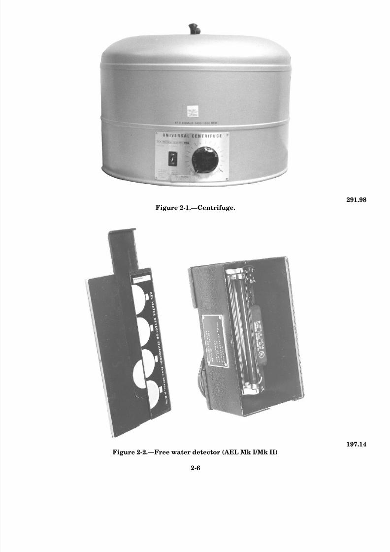
8/14/2019 US Navy Course NAVEDTRA 14115 - Gas Turbine Systems Technician Mechanical) 2
http://slidepdf.com/reader/full/us-navy-course-navedtra-14115-gas-turbine-systems-technician-mechanical 44/349
291.98
Figure 2-1.—Centrifuge.
197.14
Figure 2-2.—Free water detector (AEL Mk I/Mk II)
2-6

8/14/2019 US Navy Course NAVEDTRA 14115 - Gas Turbine Systems Technician Mechanical) 2
http://slidepdf.com/reader/full/us-navy-course-navedtra-14115-gas-turbine-systems-technician-mechanical 45/349
Centr i fuge
Figure 2-3.—Contaminated fuel detector (AEL Mk III).
You will use a centrifuge to test fuels and lubricating
oils for bottom sediment and water (BS&W). Thecentrifuge you use must be capable of holding at leasttwo 100-milliliter pear-shaped tubes. The type of
centrifuge you will likely use is shown in figure 2-1.It is capable of holding four tubes at one time. It also
has an adjustable speed control rheostat, which will
allow you to raise and maintain the rotational speedbetween 1,400 to 1,500 rpm.
To operate this unit safely, remember it is a
rotating piece of equipment. Always keep your handsand all objects away from the unit while it isoperating. Never open the unit while it is operating.
Before you operate the centrifuge, always makecertain the tubes are free from cracks and they are
properly capped. Also, make sure the unit is sitting
on a level surface and the tubes are equally spaced tomaintain proper balance.
AEL Mk I/ Mk II
The AEL Mk I/Mk II free water detector is shownin figure 2-2. You will use this instrument to measure
the amounts of free or mechanically suspended waterin diesel fuels, naval distillate, and JP-5. To operatethe unit safely, follow the precautions mentioned
earlier for the safe operation of electrically poweredequipment.
AEL Mk III
The AEL Mk III contaminated fuel detector isshown in figure 2-3. It is the most extensively used
unit
2 -7

8/14/2019 US Navy Course NAVEDTRA 14115 - Gas Turbine Systems Technician Mechanical) 2
http://slidepdf.com/reader/full/us-navy-course-navedtra-14115-gas-turbine-systems-technician-mechanical 46/349
291.99
Figure 2-4.—Flash point tester.
for fuel testing. Like the AEL Mk I/AEL Mk II,you will use the AEL Mk III to test diesel fuel,naval distillates, and JP-5. If this unit is notoperational, you will not be able to determine thequantity of solid contaminates or free watercontent in the fuel. The reason for this is the AELMk I/Mk II requires the fuel to be drawn throughits detector pad by the AEL Mk III pump.
Although it is portable, the AEL Mk III shouldbe mounted in a permanent location so it will stay
within its proper calibration requirements. Everytime this unit is moved, it must be recalibrated. Itshould only be moved if it is being replaced orrepaired.
The primary safety factor you must consider isto make sure the grounding probe is in goodworking condition and that you, and other oil labpersonnel, use it properly. You must use thegrounding probe to ground the metal filter holder
to the unit case. The grounding function transfersthe static electric charge that is created as the fuelis drawn from the plastic bottle through the filterholder.
Flash Point Tester
The flash point tester shown in figure 2-4 is theonly type of flash point tester that is authorizedfor shipboard use. It is classified as a closed-cuptester because the liquid being tested is heated by
an electric element and not an open flame. You will use this tester to determine the flash
point of a specific petroleum product. Before youuse it, however, always thoroughly clean and dryall parts of the cup and its accessories. Be sure toremove any solvent that was used to clean theequipment. These steps will help you make certainthe solvent will not contaminate the fuel or comein contact with the heating element.
2-8

8/14/2019 US Navy Course NAVEDTRA 14115 - Gas Turbine Systems Technician Mechanical) 2
http://slidepdf.com/reader/full/us-navy-course-navedtra-14115-gas-turbine-systems-technician-mechanical 47/349
Figure 2-5.—Boiler water testing cabinet (inside view).
As shown in figure 2-4, bottled propane is usedwith the tester to supply gas to the test flame.When the tester is not in use, you should make
certain the propane bottle is properly stowed.Because the thermometer in the unit contains
mercury, it must be audited by the hazardousmaterials officer (usually the supply officer). Useand store this thermometer carefully to avoid
breaking it. If it should break be sure to contact
your ship’s hazardous materials spill team.
Boiler Water Testing Cabinet
A typical boiler water testing cabinet is shownin figure 2-5. This portable, steel cabinet contains
the primary equipment and chemicals you willneed to perform approximately 90 percent of all
water chemistry testing. It is equipped with an
internal light and a door that can be locked for
safety purposes. Although the cabinet is portable,for shipboard use it is normally bolted to theworkbench.
Conductivity Meter
With the removal of carbon steel steam-
generating tubes and the installation of stainless-
steel ones, the WHB water chemistry testingprogram has undergone several changes over the
years. One of these changes was the deletion of pHlevel testing and the start of conductivity testing.
To implement this change, U.S. Navy ships havebeen equipped with conductivity meters. There aretwo types of conductivity meters currently in use.
The older meter requires a warm-up
2-9

8/14/2019 US Navy Course NAVEDTRA 14115 - Gas Turbine Systems Technician Mechanical) 2
http://slidepdf.com/reader/full/us-navy-course-navedtra-14115-gas-turbine-systems-technician-mechanical 48/349
Figure 2-6.—Conductivity meter.
period. The newer meter does not require a warm-up period. The newer model is shown in figure 2-6.
SAMPLING AND TESTING FUELS,OILS, AND WATER
Fuels, oils, and water are essential products forthe operation of your ship. Your most importantconcern will be maintaining the quality of theseproducts. By using the proper sampling andtesting procedures, you will play an important rolein keeping your ship’s engineering equipment andsystems in top operating condition. In thepreceding section, we have focused on the safetyprecautions you must use. In this section, we willdiscuss the basic procedures you should follow tosample, test, and analyze the quality of your ship’sfuels, oils, and water supplies.
Sampling and testing are two separateprocesses, each with its own set of required tasksfor a particular product. For this reason, we willdiscuss each of these processes in terms of thebasic tasks involved for each product. Just as withany other set of procedures or tasks, you shouldnever rely solely on your memory. Every task wewill discuss has a specific written procedure in
either the EOSS, the PMS, or an NSTM. Youshould always use the specific procedures andguidelines authorized for your ship. In thefollowing sections, we will briefly describe some of the most important tasks and procedures. We willalso point out some common mistakes.Understanding this information and rememberingthe safety precautions you have just read shouldhelp you become a more proficient and productiveengineer.
FUELS
Sampling and testing are continuous tasks that
allow you to make certain your ship receives thebest quality fuel and that contamination levelsremain within the acceptable specified militarystandards. Fuel contamination can originate froma variety of sources. Fuel tanks can becontaminated by rust particles. Rust particles canbe caused by moisture from air vents,condensation on tank surfaces, and the settling of solids and residues picked up during fueltransfers. Consequently, you may have to performsome type of sampling or testing procedure eachtime your ship prepares to receive, move, stow, oruse fuel products. In the following paragraphs, wewill discuss some of the methods you will use to
sample fuels. We will begin our discussion with F-76 (naval distillate) because you will need tosample this fuel frequently.
F-76 (NAVAL DISTILLATE)
You will sample F-76 (naval distillate) morethan any other fuel product. The information inthe following paragraphs will introduce you tosome of the more commonly used methods,equipment, sampling locations, and standards fornaval distillate.
Sampling
Simply stated, sampling is a visual inspection.It is the first, simplest, and most frequentprocedure you will perform on fuels. A fuel sampleis a small part or quantity of fuel that is drawn for
visual or laboratory
2-10

8/14/2019 US Navy Course NAVEDTRA 14115 - Gas Turbine Systems Technician Mechanical) 2
http://slidepdf.com/reader/full/us-navy-course-navedtra-14115-gas-turbine-systems-technician-mechanical 49/349
Fi gure 2-7.—Soun ding tube oi l sam plers.
inspection because it is representative of the qualityand condition of the total quantity of that fuel.
METHODS AND EQUIPMENT.– The methods
you will use to obtain F-76 samples include tankbottom sampling and pressurized sampling. Toperform tank bottom sampling, you will use a
common thief sampler, such as one of those shown infigure 2-7. To perform pressurized sampling, you will
need standard equipment items, such as a samplebottle, a bucket, rags, and the required personalprotective equipment.
LOCATIONS.– Regardless of the type of fuelsystem on your ship, your ship must be equipped with
valve connections at certain locations. As a minimumrequirement, your ship should at least have required
valve connections in the following areas:
• Each deck fill connection
• Each centrifugal purifier clean-fueldischarge
• Each filter/separator (coalescer) clean-fueldischarge
• Each stripping pump discharge
• All sounding tubes
For you to obtain a representative sample, the
sounding tubes in your ship’s fuel tanks must beperforated along the entire length of the tube.
Regardless of the location and method you use totake fuel samples–whether it is from a deck riser at a
fueling station, a thief bottom sample, or a samplefrom the system piping–remember to follow the safety
precautions we have discussed and the guidelines in
NSTM, chapter 541, “Petroleum Fuel Stowage, Use,and Testing” and chapter 542, “Gasoline and JP-5
Fuel Systems.”
STANDARDS.– After you take an F-76 sample
you must visually inspect it. In some cases, you mustdetermine quickly if the fuel is suitable for use or if
2-11
8/14/2019 US Navy Course NAVEDTRA 14115 - Gas Turbine Systems Technician Mechanical) 2
http://slidepdf.com/reader/full/us-navy-course-navedtra-14115-gas-turbine-systems-technician-mechanical 50/349
another form of testing is required. All fuels should have
a clear and bright appearance. Your sample will have a
clear appearance when solids are not present. Your
sample will have a bright appearance if there is no free
water present.
CONDITIONS AND FREQUENCY.– There are
many conditions for which you will be required to take
F-76 samples. During a refueling evolution, for
example, you must sample F-76 from the deck
connection at the beginning, middle, end, and every 15minutes until the evolution is completed. After sampling
F-76, you may determine that additional tests are
needed. Any time you prepare to test F-76, of course,
you must first obtain a sample. For this reason, we will
continue our discussion of sampling requirements in the
following section on fuel testing.
Testing
You will routinely use the following tests to check
the quality of your ship’s fuels:
. BS&W test
l API gravity test
. Flash point test
. Water contamination tests
We will describe these tests in the following paragraphs.
First, however, let’s look at some of the conditions that
will require you to perform these tests. After we explain
the requirements, we will describe each of the tests,
using F-76 as a typical fuel sample.
REQUIREMENTS AND CONDITIONS.– As aGSM assigned to the oil lab, you should be able to
recognize when you will need to perform routine tests
and when you will need to use additional tests to check
the fuels your ship receives. You will perform routine
tests during a refueling evolution. You must, however,
recognize the different requirements for when your ship
receives fuel from a contracted U.S. government supply
source or a non-U.S. government source. In the
following sections, we will explain these requirements.
Refueling Evolution.– In addition to the visual
sampling requirements previously mentioned, you must
also perform a BS&W test on the samples taken at the
start, midpoint, and end of the refueling evolution. The
sampling procedures and BS&W tests are routine testing
requirements. If at any time during refueling you
discover free water in any of the samples, stop receiving
the fuel until you can locate the source of the
contamination and correct it.
U.S. Government Supply Source.– If your ship is
receiving fuel from a U.S. government supply source,
the only required tests you must perform are the visual
inspections (samples) and the three BS&W tests
discussed in the preceding paragraph.
Non-U.S. Government Supply Source.– If your
ship is receiving fuel from a non-U.S. government
supply source, you must send a representative (if
possible) to the supplier to witness the gauging,
sampling, and laboratory analysis of the fuel. At a
minimum, your ship’s representative should observe
while the fuel is being tested for flash point, API gravity,
and BS&W. The flash point, especially, must be
determined before your ship can be authorized to receive
the fuel. You must determine the API gravity and BS&W
of the transferred fuel.
BS&W TEST.– You will routinely perform the
BS&W test to determine the sediment and water content
in your ship’s fuels. Sediment and water are often
present in heavy fuels. Too much water and sediment in
a fuel can cause blockage in the spray nozzles and poorcombustion of the fuel. In a fuel sample, the maximum
allowable percentage of BS&W is 0.1 percent.
To determine the BS&W, you will need a standard
sample bottle, two 100-milliliter (mL) centrifuge tubes,
and a centrifuge. Use the following steps:
1.
2.
3.
4.
5.
6.
7.
Use the standard sample bottle to obtain the
sample. The temperature of your sample must
not be below 60°F (15.5°C).
Thoroughly agitate the sample. This is an
important step for accurate readings. You mustthoroughly agitate your sample before you
continue to the next step.
Measure exactly 100 mL of the sample into each
of the two centrifuge tubes and tightly cap both
tubes.
Place the tubes on opposite sides of the
centrifuge and whirl for 10 minutes at
approximately 1,500 rpm.
After the unit has completely stopped, remove
each tube, read the volume of water and
sediment at the bottom, and record the results.
Place the tubes back in the unit and centrifuge
for 10 more minutes.
Again, remove the tubes (when the centrifuge
has stopped rotating) and read and record the
results.
2-12

8/14/2019 US Navy Course NAVEDTRA 14115 - Gas Turbine Systems Technician Mechanical) 2
http://slidepdf.com/reader/full/us-navy-course-navedtra-14115-gas-turbine-systems-technician-mechanical 51/349
8. Repeat steps 6 and 7 until the volume of water
and sediment in each tube is the same (for that
tube) for two consecutive readings. (You can
usually obtain these readings within four
repetitions.)
Your readings will indicate a direct percentage of
water and sediment. (You will not have to make
conversions because you are using 100 mL of fuel in
each tube.) By using two tubes, you are checking the
samples against each other for accuracy, Therefore,
when you are determining your final reading and both
tubes have an equal amount of sediment and water, use
only the results of one tube to record the final reading.
If the tubes should have different amounts of sediment
and water, add the readings of both tubes together and
divide by 2 to get the proper total.
API GRAVITY TEST.– You will use the API
gravity test to check the actual weight (volume) of a fuel
that is transferred to your ship from a non-U.S.
government supply source. This test will allow your ship
to have a more accurate account of the actual amount of
fuel your ship will receive.For this test, you will use a clear, smooth glass
container, a stirrer that will reach the bottom of the
container, a hydrometer, a temperature standard of 60°F
(15.5°C), and the conversion charts in NSTM, chapter
541, “Petroleum Stowage, Use, and Testing.” Use the
following steps:
1.
2.
3.
4.
5.
Fill the container with a fuel sample. Make
certain the temperature of the fuel sample is
approximately the same as the temperature of
the surrounding air.
Use the stirrer to agitate the sample thoroughly.
Check the hydrometer to make sure it is clean,
dry, and at about the same temperature as your
fuel sample. Gently lower the hydrometer into
the fuel sample, release it, and allow it to sink
into the sample slightly beyond the point where
it floats naturally. Allow the rise and fall of the
sample to cease and the hydrometer to reach
equilibrium before you continue to the next step.
Read the scale. Make certain your eyes are on
the same level as the surface of the sample. Read
the hydrometer scale at the point that appears tocoincide with the top of the sample.
Convert your reading to the petroleum industrial
standard of 60°F (15.5°C) by referring to the
conversion tables in NSTM chapter 541. Use one
table to find the corresponding industrial
standard for your reading. Refer to the next table
to find the volume correction factor. Take the
volume correction factor and multiply it with the
amount of fuel volume in the tank you are
testing. The result should provide you with the
actual weight or volume of the sampled fuel
according to the industrial standard and should
represent the actual weight of the fuel your ship
will receive from the non-U.S. government
source.
FLASH POINT TEST.– You will use the flash
point test to determine the flash point of a fuel your ship
has received on board. The minimum flash point for all
fuel on Navy ships is 140°F (60°C).
For this test, you will need a closed-cup flash point
tester and a 90 millimeter (mm) paper filter. Use the
following steps:
1.
2.
3.
4.
5.
6.
7.
8.
Thoroughly clean and dry all parts of the cup and
its accessories. Make sure there are no traces of
cleaning solvent on the unit or its accessories.
Filter the fuel sample through the filter paper toremove all traces of water.
Fill the test cup with the fuel sample to the level
indicated as the filling mark. Place the lid on the
cup.
Set the cup in the oven. Be sure you have the
locking device properly engaged. Insert the
thermometer.
Light the test flame and adjust it to 5/32 inch (4
mm) in diameter. Adjust the oven heat so the rate
of temperature rise for the fuel (as indicated by
the thermometer) is 9°F (5°C) to 11°F (6°C) perminute.
Turn the stirrer 90 to 120 rpm in a downward
direction. Now, turn the stirring unit off before
you continue to the next step.
Making sure the temperature of the sample is not
any higher than 30°F (17°C) below the expected
flash point, use the cover mechanism that
controls the shutter and test flame burner to
lower the test flame into the fuel cup. (Lower the
flame into the vapor space of the cup in 0.5
second, leave the flame in its lowered position
for 1 second, and quickly raise it back up.)
Reapply the test flame at every 2°F (1.1°C)
interval.
When the test flame causes a distinct “flash” in
the cup, record the temperature indicated. Do not
2-13

8/14/2019 US Navy Course NAVEDTRA 14115 - Gas Turbine Systems Technician Mechanical) 2
http://slidepdf.com/reader/full/us-navy-course-navedtra-14115-gas-turbine-systems-technician-mechanical 52/349
confuse the true flash point with the bluish halo
that may surround the test flame until the real
“flash” occurs.
WATER CONTAMINATION TEST.– If you
happen to be aboard a ship, such as an FFG, that has
noncompensated fuel oil storage tanks, you must
perform a water contamination (water cut) test. You
should perform this test 24 hours after the receipt of fuel.
If water is present, the tank must be stripped. You must
retest the tank until the fuel meets the requirements set
forth in NSTM chapter 541. Use the procedures in the
following paragraphs.
Service Tank Replenishment.– Noncompensated
fuel oil storage tanks contain the fuel products that will
be used to replenish the main and auxiliary service tanks
of your ship. For this reason, you must test
noncompensated storage tanks for water contamination
and strip them as necessary before the fuel transfer takes
place.
Five minutes after the start of the fuel transfer and
every 30 minutes thereafter, you must sample and
visually inspect the purifier discharge. Your sampleshould meet the clear and bright criteria. If the sample
fails, you need to inspect the tank and clean the purifier.
Once the service tank is replenished, you should
recirculate the fuel. If your ship is equipped with
self-cleaning purifiers, recirculate the fuel in the service
tank for at least 3 hours and as long as possible after this
period. Even if your ship is equipped with manual
purifiers, you should still try to recirculate the fuel forat least 3 hours after replenishment. A properly working
purifier can remove 10 to 50 percent of contaminants in
a single pass. If you operate the purifier for multiple
passes (3 hours), you can remove as much as 90 percent
of the total contaminants. By reducing the level of
contamination in the service tank, you are also reducing
use of the coalescer, separator, and prefilter elements.
As an additional precaution, you must make sure the
purifier bowl is cleaned regularly. If the purifier bowl is
not clean, recirculating the fuel will be of little value. If
the service tank remains idle for over 48 hours,
recirculate the fuel for at least 3 hours.
Your ship can minimize the entry of pollution-laden
harbor water into the compensated fuel tanks by topping
off the service tanks before entering port and by not
transferring fuel between groups. In the same way, your
ship should never use harbor water as tank ballast for
noncompensated fuel stowage tanks.
Service Tank Operations.– Before placing the
auxiliary (standby) service tank in use, you must test the
tank bottom for water contamination and strip it as
necessary. When the service tank is suitable for use,
sample and test the filter/separator discharge 5 minutes
after you place the tank in service and at least once every
4 hours during system operation. To test the fuel, you
will use the AEL Mk I/II and AEL Mk III testers. You
will use the AEL Mk III first.
AEL Mk III.– The AEL Mk III is a portable fuel
detection unit. It consists of a fuel sample container, a
fuel millipore filtration system (with the filter), and a
light transmission system that will determine the
quantity of solids contamination trapped on the
millipore filter. All the equipment and parts you will
need are stored in the unit. Before you begin the test,
however, there are two things you must check: (1) Make
sure the calibration chart is up to date, as it must be
updated quarterly according to the PMS, and (2) make
sure the fuel flask is empty. If you have to drain the flask,
turn the drain handle to allow the fuel to drain through
the tygon tubing to the waste fuel container. Once the
fuel has drained, close the drain cock Now take the
following steps:
1.
2.
3.
4.
5.
6.
7.
Disassemble the filter holder and bottle
receiver assembly by turning the center locking
ring in a counterclockwise direction and
pulling apart the two components. Insert the
filter holder (the equipment with the rubber
stopper) into the opening in the fuel flask.
Using the forceps, place two millipore filters
on the rubber stopper side of the assembly
(filter screen). Do not touch these filters with
your hands!
Reassemble the filter assembly and
temporarily place it in the opening of the fuel
flask. Now, turn on the light switch so the unit
can warm up.
Fill the plastic bottle with 200 mL of the fuel
sample.
Remove the filter assembly from the fuel flask
opening and install it on the plastic sample
bottle. Make sure the entire threaded portion of
the sample bottle is inserted into the filter
assembly.
Insert the ground wire into the receptacle nextto the fuel flask opening. Quickly invert the
sample and place it into the fuel flask opening.
Now, turn on the pump.
After all the fuel has drained from the sample
bottle, carefully remove the bottle from the
2-14

8/14/2019 US Navy Course NAVEDTRA 14115 - Gas Turbine Systems Technician Mechanical) 2
http://slidepdf.com/reader/full/us-navy-course-navedtra-14115-gas-turbine-systems-technician-mechanical 53/349
Fi gure 2-8.—Calibratio n ch art.
filter assembly. Watch to make sure all the fueldrains through the filters. Next, turn off thepump. By now, the light should have had
sufficient time to warm up and you can proceedwith the calibration process, starting with the
next step.
11. Making sure there is no filter in the receptacleand the photocell is clean, swing the photocellinto the measuring position. Use the rheostat
knob to adjust the millimeter until you get areading of 0.6.
12. Using the forceps, pick up the contaminated
filter. Wet the filter completely by pouring a
small amount of clean F-76 on the workingsurface and laying the filter in it. Make sure
you get the entire filter wet with fuel. 13. Using your forceps, place the wet filter in the
measuring receptacle under the photocell.Record the reading on the millimeter andremove the filter. Now, repeat the process with
the second filter.
14. Subtract the contaminated filter reading (filter
No. 1) from the clean filter reading (filter No.
2). Find the corresponding contamination value in milligrams per liter (mg/L) on thecalibration curve chart, such as the one shownin f igure 2-8. Calibration chart readings of 5
mg/L or less are acceptable and equate to 2.64mg/L or less. You will not need to make
corrections for sample size.
With a little practice, you will have no difficulty
using the calibration curve chart. For example, takethe following numbers and plot them on the chart in
figure 2-8: Filter No. 1 (contaminated) equals 0.02milliamps. Filter No. 2 (clean) equals 0.06. Subtractthe reading for filter No. 1 from that of filter No. 2 .
Your answer should equal 0.04 milliamps. To find themg/L reading, look on the left side of the chart and
locate 0.04 milliamps. Draw a straight line across thechart until you intersect the calibration line. At thispoint, move your pencil straight down to find the fuel
contamination level. If you have done these stepscorrectly, you should have a reading of 1.6 mg/L.
2-15

8/14/2019 US Navy Course NAVEDTRA 14115 - Gas Turbine Systems Technician Mechanical) 2
http://slidepdf.com/reader/full/us-navy-course-navedtra-14115-gas-turbine-systems-technician-mechanical 54/349
Now that you have determined the contamination
level of your fuel, you can proceed with the free water
test. For this test, you will use the AEL Mk II free water
detector as well as some parts of the AEL Mk III.
AEL Mk II.– The AEL Mk II free water detector
consists of three main parts: (1) a view box containing
an ultraviolet light source; (2) a set of printed standards,
indicating 0, 5, 10, and 20 ppm; and (3) some water
detector test pads. To maintain detector accuracy, you
must replace the printed standards every 6 months. Thewater detection pads are extremely sensitive to moisture
in the air. To avoid false readings, avoid drawing air
through these pads at times other than when your fuel
sample has passed completely through the pad. Keep
these precautions in mind as you take the following
steps:
1.
2.
3.
4.
5.
6.
7.
8.
9.
Using the same fuel sample bottle you used
with the AEL Mk III, fill the bottle to the 200
mL mark with F-76.
Open a free water detector envelope. Using the
forceps, pick up the detector pad and place it,orange side up, on the contaminated fuel
detector filter base. Attach the bottle receiver to
the filter base and plug in the ground wire jack.
Check to make certain the fuel flask is empty
and the drain valve is closed.
Shake the sample bottle vigorously for at least
30 seconds. Immediately turn on the vacuum
pump. Unscrew the bottle cap and place the
bottle receiver and pad holder assembly firmly
over the end of the sample bottle, making sure
the entire threaded portion of the bottle top isinserted into the bottle receiver.
Pick up the entire assembly, invert it, and insert
the pad holder end into the fuel flask of the AEL
Mk III. Do steps 4 and 5 quickly to keep the
free water in suspension.
Observe the filtration process. Once the entire
sample has passed through the detector pad,
turn off the vacuum pump. Remove the bottle
and the bottle receiver.
Using your forceps, remove the detector pad
from the filter base and place it, orange side up,in the free water detector slide depression.
Hold the light switch in the ON position and
insert the slide containing the test pad.
Look through the view port of the box. To
determine the amount of free water, compare
10.
the brightness of the fluorescence of the test
pad with that of the standards. The numbers
located directly above the standards will
indicate the free water content in ppm. If the
chart reading is 5 ppm or less, then the level of
free water is acceptable. A chart reading of 5
ppm or less equates to an actual limit of about
40 ppm or less. You will not need to make
corrections for sample size.
Your last step is to drain the fuel from the flaskof the AEL Mk II through the tygon tubing.
Up to now, we have discussed sampling and testing
requirements and procedures for F-76. In the following
sections, we will discuss the procedures you will need
to use for F-44, commonly called JP-5.
F-44 (JP-5)
Although most o f your fuel sampling
responsibilities will involve F-76, you also will be
involved with maintaining the quality of F-44. F-44 has
two principal uses on board gas turbine-powered ships.
Its primary use is for the service of aircraft. Its secondary
use is for the ship’s boats. Maintaining a high quality of
this product is very important. As you read about the
sampling and testing procedures for F-44, notice how
the quality requirements for F-44 are much more
stringent than those for F-76.
Sampling
In sampling F-44, you will use the same visual
sampling criteria (clear and bright) as you would for
F-76. The main difference in the sampling requirements
is that you must sample F-44 fuels more frequently, Theconditions under which you must sample F44 and the
frequency with which you must take these samples are
listed in NSTM, chapter 542, “Gasoline and JP-5 Fuel
Systems.” As we are unable to cover the multitude of
conditions and circumstances within the scope of this
TRAMAN, we recommend you consult NSTM, chapter
542, for detailed instructions.
Testing
You will basically use the same tests and testing
procedures for F-44 as you would for F-76. The main
difference is that the testing requirements for F-44 arestricter than those for F-76. The stricter requirements for
F-44 apply mainly to the following maximum allowable
contamination limits:
l Solids contamination must not exceed 2.0 mg/L.
. Free water content must not exceed 5 ppm.
2-16

8/14/2019 US Navy Course NAVEDTRA 14115 - Gas Turbine Systems Technician Mechanical) 2
http://slidepdf.com/reader/full/us-navy-course-navedtra-14115-gas-turbine-systems-technician-mechanical 55/349
Fi gure 2-9 .—FSII refract om et er.
The methods you will use to test F-44 are the sameones we just described for F-76 fuels.
In addition to the tests you will perform on both F-76 4. and F-44 fuels, you must perform one other test
on F-44. In this test, you will check for fuel systemicing inhibitors (FSII). For this test, you will use the
FSII refractometer kit, as shown in figure 2-9. View Aof figure 2-9 shows the components of the test kit andthe 5. set up. Views B and C show front and side
views of the refractometer.
As the name implies, the refractometer uses lightto 6. indicate inhibitor levels. You must handle therefractometer with care. It is delicate and can be
damaged easily. You can use either a fluorescent oran incandescent light source, but the area in whichyou perform test, must be well lighted. To perform
the test use the following steps:
1. Set up the refractometer ring standassembly, as shown in view A of figure 2-9.
2. Using a clean sample bottle, take a 1-quart
sample of the F-44 you will test.
3. Fill the aluminum dish that comes with the
kit one-half full. (If the dish that comeswith the kit is damaged or missing, you canuse any clean dish.)
4. Fill the graduated cylinder and the
separator funnel about one-third full of thetest fuel. Swish the fuel around in both thecylinder and the funnel to clear away any
foreign material, then toss it out.
5. Fill the graduated cylinder with exactly 160mL of the fuel sample. (Make sure thedrain cock on the separator funnel is
closed.)
6. Pour the fuel from the graduated cylinderinto the separator funnel.
7. Using the piston pipets or an eye dropper,add exactly 2 mL of water from the
aluminum dish to the separator funnel.Place the cap on the funnel.
8. Shake the funnel for at least 3 minutes,then place it on the ring stand.
9. Open the hinged plastic cover on the
window of the refractometer. Make sure the
window and cover are clean. Place severaldrops of water on the window. Close thecover and look through the eyepiece.
Observe the shadow line.
2-17

8/14/2019 US Navy Course NAVEDTRA 14115 - Gas Turbine Systems Technician Mechanical) 2
http://slidepdf.com/reader/full/us-navy-course-navedtra-14115-gas-turbine-systems-technician-mechanical 56/349
Figure 2-10.—Views through a refractometer.
Remove the black plastic rod from thebottom of the refractometer. Using the rod
(or a screwdriver), adjust the setscrewuntil the shadow line meets the zero line of the scale, as shown in figure 2-10. (Study
views A and B.)
NOTE
What you have done is added water to thefuel. By shaking the sample, you haveallowed the icing inhibitor to leach into the
water. By adjusting the setscrew until youread zero, you have made the refractometer
ready to compare the FSII in the fuel to thescale inside the instrument.
10. Open the plastic cover and wipe thewater from the window and cover.
Carefully turn the drain cock so severaldrops of water can trickle into a clean,dry aluminum dish. Open the hinged
plastic cover and place two or threedrops of water from the funnel on the
window. Close the cover. Look throughthe eyepiece and read the point wherethe shadow line is on the scale. This
reading should give you the percentageof FSII by volume. (Study view C.)
NOTE
Remember to put only water on therefractometer, no fuel. Use clean water or
water with additives only. If fuel is in thesample you put on the refractometer, you may
get a false reading.
11. Upon completion of the test, empty thefunnel and properly dispose of the fuel.Clean the equipment with soap and
water, then thoroughly rinse it withwater.
OILS
In the oil lab, your job of sampling and
testing oils (lubricants) will be extremelycritical to the effective operation of your ship’sengineering equipment and systems. Oils
reduce friction, dissipate heat, and prevent
corrosion. In addition, they conduct friction-generated heat away from bearings, act as aseal to protect lubricated areas fromcontamination, and act as a carrier for
materials such as rust preventatives, anti-friction agents, and extreme-pressure
additives.
Contamination of oils can seriously harm
equipment. Contamination occurs in oilsmuch in the same manner as it does in fuels.
Whereas fuels are really used only once, oils
are purified and used over and over again.This is where a good sampling and testing
program comes into play.
In the following sections, we will discusstypical sampling and testing procedures foroils. In most of our discussions, we will use
2190 TEP as a typical oil because you willcome into contact with this oil more than any
of the others. Later in this section, we alsowill tell you about the other types of oils andthe sampling and testing procedures you will
be required to perform on them. Because you
will perform sampling more frequently thantesting, let’s talk about oil sampling first.
SAMPLING
Oil sampling will always be your simplest,
most frequently used, and first-line procedureof defense against equipment failure. While
assigned to the oil lab, you will need to knowthe conditions for which you
2-18

8/14/2019 US Navy Course NAVEDTRA 14115 - Gas Turbine Systems Technician Mechanical) 2
http://slidepdf.com/reader/full/us-navy-course-navedtra-14115-gas-turbine-systems-technician-mechanical 57/349
should take oil samples and the frequency with which
you should perform sampling procedures.
Conditions and Frequency
You should take oil samples for shipboard testing at
the intervals specified by the PMS, the EOSS, or the
applicable technical manuals for your ship. Unless
otherwise specified in these documents, you should
sample all equipment at the following times:
l Before start-up
l 30 minutes after start-up
l Daily thereafter
In addition, you must sample idle equipment weekly. Be
sure to check all equipment for proper oil levels before
and after sampling.
You also should sample when unusual conditions
occur, such as abnormal changes in temperature,
pressure, vibration, or noise levels. You should always
sample whenever you observe an abnormal symptom,
such as a sudden oil color change, foaming in the sight
glass, and excessive leakage, venting, or oil
consumption.
NOTE
Normal lube oil sampling and testing
requirements do not apply during engineering
casualty control drills. For equipment involved
in casualty control drills, test the oil 1 hour
before the beginning of the drills and 1 hour
after the completion of the drills.
Methods
The three oil sampling methods you will commonly
use aboard ship are: (1) thief, (2) static, and (3)
pressurized. In the following paragraphs, we will
discuss these methods and the equipment you will need.
THIEF METHOD.— Thief sampling is the method
you will use primarily to sample the bottom of theequipment sump (like that on the main reduction gear)
before the lube oil service pumps are started. You will
use a thief sampler (sounding tube sampler) similar to
one of those shown in figure 2-7. If the sump has a
sounding tube, you must use a pail, a clean 8-ounce
sample bottle, rags, and a thief sampler. (If the sump
does not have a sounding tube, you will be required to
use the pressurized sampling method, which we wil
discuss later.) Use the following steps:
1.
2.
3.
4.
5.
6.
Clean the area around the sounding cap and
remove the cap.
Attach the thief sampler to the sounding tape an
lower it into the sump. Do this slowly so th
sampler will gently hit the striker plate at th
bottom. You can damage the sampler if you le
it hit the striker plate too hard. If you are no
familiar with the depth of the tank, measure ifirst. Then, you can use the sounding tape t
measure the distance from the top of th
sounding tube to the striker plate before you
attach the sampler. Remember, the soundin
tape plumb bob is approximately 4 inche
shorter than the sampler.
Once the sampler is at the bottom of the tank
you can take a sample. However, you will no
keep this sample. You will use it to flush out th
sample bottle. Remember to keep the sampl
bottle capped or closed promptly after you tak
the sample to prevent contamination.
After flushing the sample bottle, dump the o
into a pail for disposal.
Fill the sample bottle. You will have to send th
sampler down several times to obtain enough oi
to fill the bottle.
Label the filled sample bottle with the followin
information:
l Equipment name
l Oil type
. Date
. Time
STATIC METHOD.— You will use the stati
method to take samples on equipment items that hav
sample connections installed on the equipment sump
The equipment items with this type of sampl
connection are usually auxiliary equipment, such as ai
compressors, line shaft bearings, and lube oil storag
and settling tanks.
For static sampling, you will use the same basi
procedures you would use for thief sampling. The onl
difference in static sampling is you must flush th
sample connection. The amount of oil you must use t
flush the connection must beat least equal to or greate
than the amount of stagnant oil already in th
connection.
2-19

8/14/2019 US Navy Course NAVEDTRA 14115 - Gas Turbine Systems Technician Mechanical) 2
http://slidepdf.com/reader/full/us-navy-course-navedtra-14115-gas-turbine-systems-technician-mechanical 58/349
PRESSURIZED METHOD.— You will be able to
perform pressurized sampling on most of the operating
equipment in the engineering plant. In fact, when you
use the pressurized method, you will be taking samples
on equipment that is already in operation. The main
problem with taking pressurized samples is that you
must take additional precautions, such as wearing
protective clothing (rubber gloves, an apron, and
chemical splash goggles), and taking extra care to avoid
an excessive loss of oil. Be very careful when you take
these samples. Try to avoid accidentally dumping the oil
from either the sump or the tank. Sound the sump on
small equipment both before and after you take the
samples because flushing and sampling can both cause
a low sump condition.
Standards
No matter what method you use, all your samples
must meet the visual inspection requirements. These
requirements, the clear and bright criteria, are basically
the same as those you would use for fuels. The only
difference is you must allow an oil sample that has a
hazy appearance to settle for 30 minutes to allow any
entrained air a chance to dissipate. If the sample clears
from the bottom to the top, you can assume the haze was
the result of entrained air. If the haze clears from the top
to the bottom, however, it is likely the result of solids or
free water contamination.
After allowing the haze to clear, you must visually
inspect the sample to determine if it is clear. Start by
inverting the sample bottle and observing the particulate
matter as it settles. Be sure to hold the bottle in theinverted position for at least 1 minute. Then, turn the
bottle in its right-side-up position for 1 minute, and then
invert it again for an additional minute. Invert the sample
bottle at least three times. If you still see any particulate
matter in the oil, the sample has failed your visual
inspection for clear and bright oil and you must perform
additional testing. The additional tests will be based on
the type of oil and the type of equipment.
TESTING
The oil testing procedures we will discuss in this
section are for transparency, BS&W, mineral oil
contamination, acidity, and fuel dilution. These tests are
usually performed either as a PMS maintenance
requirement or under special conditions. In the
following sections, we will describe each of these tests.
Later, we will tell you about each oil type, its testing
requirements, and whether the tests are routine or
conditional.
Transparency Test
Systems without online purification capability
sometimes have difficulty maintaining a clear and bright
oil condition. In such equipment, frequent oil changes
to maintain a clear and bright condition are time
consuming and costly. In these cases, you should
perform the transparency test.
First, place a PMS card behind the sample bottle in
a well-lighted area. Be sure to hold the card directly
against the sample bottle. Try to read the printed words
on the card. If you can read the words, the oil passes the
transparency test. If you can not read the words, the oil
fails the test. If the oil passes the transparency test, it is
satisfactory for use. If it fails the test, your next step is
to perform the BS&W test.
BS&W Test
You will perform the BS&W test on all types of oils.
The BS&W test you will perform on oils is very similar
to the one we described for fuels. Since the procedure is
basically the same, we will just discuss the differences.
The only differences in the procedure for oils are that
you must (1) dilute the oil sample, and (2) add the water
and sediment readings of both tubes to get the final
readings.
To dilute the oil sample, add exactly 50 mL of a
water-saturated mixture of dry-cleaning solvent
(P-D-680, type II) to each of the two 100 mL tubes. After vigorously agitating the oil sample, pour the oil into each
of the 100 mL tubes. Pour enough oil into each tube to
make up the remaining 50 mL. Agitate each tube to make
sure the oil and dry-cleaning solvent are completely
mixed. Invert each tube at least five times. Allow the
liquid to drain thoroughly from the tip of the tube each
time you invert it. Now check your readings against the
following standards:
1. If the sediment is less than or equal to 0.1 percent
and the combined BS&W is less than or equal to 0.2
percent, the oil is satisfactory for use.
2. If the sediment is less than or equal to 0.1 percent
and the combined BS&W is somewhere between 0.2
and 0.4 percent, the equipment is in a warning condition.
In this case, you need to identify the cause of the
contamination and correct it. Either purify the oil or
replace it with clean oil when the equipment is secured.
Do not operate the equipment longer than 7 days after
2-20
8/14/2019 US Navy Course NAVEDTRA 14115 - Gas Turbine Systems Technician Mechanical) 2
http://slidepdf.com/reader/full/us-navy-course-navedtra-14115-gas-turbine-systems-technician-mechanical 59/349
you identify the contamination unless you obtain written
authorization from the commanding officer. For secured
equipment, have the oil either purified or changed
before the equipment is readied for operation.
3. If the combined BS&W exceeds 0.4 percent or
if sediment exceeds 0.1 percent at any BS&W level, the
oil is at the condemning limit. In this case, you must
secure the equipment unless the commanding officer
authorizes its continued use in writing.
Mineral Oil Contamination Test
You will use the mineral oil contamination test on
synthetic oils. In fact, you must routinely test synthetic
oils for mineral oil contamination. Mineral oil
contamination is always a possibility because of the
configuration of the synthetic oil cooling systems.
According to the PMS, you will routinely perform the
test for mineral oil contamination every month. Use the
following steps:
1.
2.
3.
4.
Mix 25 mL of synthetic oil with 75 mL of
absolute methanol in a 100-mL graduated
cylinder that you can cap.
Seal the container and shake it vigorously.
Observe the liquid. If the liquid appears cloudy,
it is contaminated with mineral oil. If the liquid
remains clear, it is not contaminated with
mineral oil.
If the oil is contaminated, find the cause and
correct it. Then, thoroughly flush the oil system
before you add new oil.
Oil Acidity Test
You will be required to perform oil acidity tests on
series 9000 (diesel) oils. You will normally conduct the
oil acidity test at least every 24 hours of engine operation
or once a week, whichever is more frequent. To perform
this test, use the following steps:
1.
2.
3.
4.
Remove the reaction vial from the test kit and
fill it to the 25-mL mark with the preprepared
reaction indicator solution.
Add the engine oil to raise the liquid level to the
40-mL level.
Screw on the top and shake the vial vigorously
for 15 seconds.
Allow the reaction vial to stand for 5 to 10
minutes until the oil and indicator separate.
2-21
5. Remove the reaction indicator card from the kit
and compare the color of the separated indicator
(lower level in vial) with the card. If the indicator
is blue, the oil is satisfactory. If the indicator in
the vial is either green or yellow, the oil is
unsatisfactory and should be changed.
Fuel Dilution and Oil Thickening Test
Like the oil acidity test, you will perform the fuel
dilution and oil thickening test on series 9000 (diesel)
oils. For the fuel dilution and oil thickening test, you will
need a sample of clean (new) lube oil as well as the
sample from the engine (used oil). Take the comparator
from its storage case and set it up on a level, stable work
area. Make sure it is firmly supported and at a slight
angle from the vertical position. Take the following
steps:
1 .
2.
Using the thermometer from the test kit,
measure the temperature of the new and used
oils to make sure the difference is not greaterthan 1°F (-17.2°C).
Fill tube A of the comparator to the gallery (the
enlargement of the diameter) with new oil and
place it in the comparator. Fill tubes 1 and 2 to
the same level with used oils and place them also
in the comparator.
NOTE
You can place samples from two differentengines in the individual comparator tubes
(tubes 1 and 2) at the same time. You will run
the test only on one used sample tube and tube
A at a time.
3.
4.
5.
Use the end buttons to lift the three rod markers
to 100 on the scale. Do not let your fingers touch
the rods. Set the comparator aside for at least 10
minutes to equalize the temperatures.
Run rods A and 1 up and down in their tubes at
least twice. Looking squarely at the markers andthe start line, set the markers of rods A and 1 at
the start line. Place the rod of the other sample
tube in the down position.
Push in the reset button. Start the rods down by
pushing and holding the release button. Then
release the button when one of the rod markers
reaches 100 on the scale.

8/14/2019 US Navy Course NAVEDTRA 14115 - Gas Turbine Systems Technician Mechanical) 2
http://slidepdf.com/reader/full/us-navy-course-navedtra-14115-gas-turbine-systems-technician-mechanical 60/349
6. Record the rod A reading in column 3 of the
diesel engine lube oil testing log. (We will
examine this log later in this chapter.) Record
the used oil rod reading in column 4 of the oil
test log.
You can now repeat the process if you are using
another used oil sample in tube 2. When you have
completed the tests, wipe the rods and the balls and drain
the tubes thoroughly. You must make certain to do this
between each test. Place the comparator back in its
storage case.
The proper analysis of the test results depends upon
the design and size of the engine from which you took
the sample. You can generally use the following
standards:
l
l
l
The normal range of fuel dilution will be within
0.5 to 2.0 percent.
Fuel dilution in the range of 2.0 to 5.0 percent
indicates either a fuel jumper line leak or faulty
injection equipment.
Fuel dilution greater than 5.0 percent should
cause you to be seriously concerned about the
fitness of the engine. In addition to checking for
jumper line leaks and faulty injection
equipment, inspect several of the engine
bearings for abnormal or excessive wear. If the
bearings are worn, you will need to make further
inspections to determine both the extent of
bearing damage and the proper repair actions.
The standards of the test are logical if you just thinkabout how the test works. In the case of fuel dilution, the
higher the fuel dilution (oil thinning), the faster the rod
will move down in the used oil than it will in the new
oil. Oil thickening, however, is just the opposite. The
carbon and sediment picked up by the oil will cause the
oil to become thicker and will cause engine damage if
the oil is not changed.
TYPES OF OILS
We have just discussed the basic tests you will berequired to perform on oil samples. We will now talk
about the different oils you will test and how the
characteristics and testing requirements will differ
depending on the type of oil and the type of equipment
using it. Since they are the most commonly used oils on
your ship, we will discuss mineral oils, or 2190 TEP,
first.
Mineral Oils
Mineral oils, commonly called 2190 TEP, are
extensively used throughout naval engineering plants.
These oils are commonly used in your ship’s main
reduction gears, controllable pitch propeller systems,
and generators.
Earlier in this section, we discussed the procedures
you should use for sampling oils. If a mineral oil sample
fails your visual inspection or remains hazy aftersettling, you will need to perform additional tests. The
tests you will perform on mineral oils are for
transparency and BS&W.
In sampling and testing mineral oils, you should be
aware of some special characteristics. Sometimes the
chemical makeup of a mineral oil will cause a good oil
not to be clear and bright at 77°F (25°C). This usually
happens when the oil is contaminated with trace
amounts of water. After the oil is heated, it becomes clear
and bright. Consequently, if you are sampling a
MIL-L-17331 (2190 TEP) lube oil and your oil sample
is not clear and bright at 77°F (25°C), use a water bath
to heat the oil to 120°F (48.8°C). For the water bath, you
will need a container of water and a heat source, such as
a hot plate. You can also use a deep sink or pot filled
with hot water. Place the sample bottle in the water and
heat the oil until it reaches 120°F (48.8°C). Observe the
oil sample periodically. If the oil becomes clear and
bright when it reaches 120° (48.8°C), it is satisfactory
for use. If the oil fails to become clear and bright after
it reaches 120°F (48.8°C), use the following guidelines:
1. If the equipment has online purification
capability, have the oil purified. If the oil is still not clearand bright after three passes through the purifier, change
it.
2. If the equipment does not have online
purification capability and you discover particulate
matter in the sample, perform the BS&W test. If the
sample is not clear and bright, perform the transparency
test.
Synthetic Oils
Synthetic oils are found in shipboard coolingsystems. You will routinely make visual inspections of
synthetic oils during sampling. In addition to
transparency and BS&W tests, there is one other
shipboard test you will need to be familiar with for
synthetic oils, the test for mineral oil contamination. In
performing this test, you should use the procedure we
described earlier.
2-22

8/14/2019 US Navy Course NAVEDTRA 14115 - Gas Turbine Systems Technician Mechanical) 2
http://slidepdf.com/reader/full/us-navy-course-navedtra-14115-gas-turbine-systems-technician-mechanical 61/349
Series 9000 Oils (Diesel)
In addition to the transparency and BS&W tests, you
will need to perform two other tests on 9000 series oils
(diesel), the oil acidity test and the fuel dilution and oil
thickening test. In performing tests on 9000 series oil
samples, follow the steps we described for each of these
tests in the preceding paragraphs.
WATER
You will sample and test water products almost as
frequently as you will fuel products. In sampling and
testing water, the primary contaminant you will deal
with is chloride. Chloride is the direct result of seawater
contamination, but other contaminants are also
produced when seawater contamination occurs. Rust
formation (corrosion) and scaling can occur in boilers,
feed tanks, piping, and diesel engines. This is why you
must frequently sample water products and provide
prompt and correct treatment for contamination levels.
The only way you can detect these contaminants is
through a program of diligent sampling and testing.
Once you detect the contaminants, you can devise a
treatment plan to control and eliminate the problem.
In the following sections, we will tell you about
various sampling locations, basic testing guidelines, and
fundamental treatment procedures for water products.
We will use different terms to refer to the water you will
sample and test at specific locations in the shipboard
water cycle. These distinctions are necessary because
water quality standards will vary throughout the system.
We will use the following terms to identify water at
various points in the system:
. Distillate—The distillate is the evaporated water
that is discharged from a ship’s distilling plant. The
water in a shipboard water cycle normally begins as
distillate. The distillate is stored in the feedwater tanks.
The chief engineer will designate one of these tanks as
the online feed tank and the others as reserve feed tanks.
The distillate will be stored in the reserve feedwater
tanks until it is needed as makeup feedwater.
. Feedwater—Very simply, feedwater is the water
(distillate) stored in the feedwater tanks. In its broad
sense, feedwater refers to all waters of the feed system,
including the reserve feedwater, makeup feedwater,
condensate, and deaerated feedwater systems. In its
narrow definition, feedwater can include different types,
depending on the location of the feedwater in the system.
l Reserve and makeup feedwater–The distillate
while stored in the feedwater tanks is called reserve
feedwater. Because gas turbine-powered ships that have
waste heat tillers do not have demineralizers, the water
in all tanks (including the tank on makeup) is termed
reserve feedwater. The water flowing to the condensate
system is referred to as makeup feedwater.
. Deaerated feedwater–Deaerated feed water is
produced from the condensate that flows from the
condenser to the deaerating feed tank (DFT) where
dissolved oxygen and other gases are removed. The
resulting deaerated feedwater then goes to the tillers.
Deaerated feedwater specifically refers to that water
contained between the DFT and the boilers.
. Condensate–Condensate is the water that results
when used steam is cooled in a condenser. After the
steam has done its work, it is coded in a condenser and
returned to its liquid state. The condenser is a heat
exchanger that uses seawater to cool the steam and turn
it into water. The liquid condensed from steam is called
condensate. Water from other sources, such as makeup
feedwater and low-pressure drains, mixes with and
becomes part of the condensate. The condensate goes to
a condensate cooler, and back to the feedwater tank.
. Boiler water–If a DFT is installed, the deaerated
feedwater, as it enters the boiler separator, becomes
boiler water. Boiler water specifically refers to the water
in the separator, headers, and generating tubes of the
boiler.
. Fresh water–Fresh water can refer either to a
ship’s potable water or to water from certain steam
drains that is returned to the condensate system.
You should routinely be able to recognize and usethese terms. Keep these terms and their definitions in
mind as you read the following sections.
SAMPLING
Sampling of water products is just as important as
sampling of fuels and oils. The primary difference is that
water products will rarely show any visible signs of
contamination. Because of this, you will draw water
samples primarily for chemical testing.
You will draw water samples from various locationsin the plant. These locations will differ according to
whether the system you are testing is operating under
normal conditions or casualty conditions. In the
following paragraphs, we will discuss when you must
take samples under normal operating conditions and the
sampling locations you should use.
2-23

8/14/2019 US Navy Course NAVEDTRA 14115 - Gas Turbine Systems Technician Mechanical) 2
http://slidepdf.com/reader/full/us-navy-course-navedtra-14115-gas-turbine-systems-technician-mechanical 62/349
Boiler Water
For your ship’s boilers to operate safely and
efficiently, you must pay careful attention to the quality
of the boiler water. Your responsibilities for sampling
boiler water will vary based upon the condition and
operation status of each boiler. In the following
paragraphs, we will talk about some of the more
common conditions you will encounter.
STEAMING BOILERS.— You should sampleboiler
times:
1.
2.
3.
4.
5.
6.
water from a steaming boiler at the following
Within 30 minutes after the generator is started.
As often as you need to maintain the chemical
limits, or at least every 8 hours. The time
between samples should not exceed 8 hours.
Within 1 hour before starting blowdowns.
Between 30 to 60 minutes after blowdowns.
Between 30 to 60 minutes after batch chemical
treatment.
Within 1 hour before the generator is secured.
When taking samples from a steaming boiler, keep
the design of the system in mind. The water and steam
mixture you will sample originates from the boiler. The
water then passes through a cooler which lowers the
water temperature to 100°F (37.7°C) or below. Each
boiler has its own cooler. For this reason, you must
designate and maintain a separate sample bottle for each
boiler. You should also follow all the safety precautions
listed at the beginning of this chapter.
IDLE BOILER.— In sampling boiler water from an
idle boiler, you will use the same locations you would
use for a steaming boiler. For an idle boiler, however,
you will only be required to sample 1 hour before a
blowdown, usually after the boiler is secured. Even if an
idle boiler has been blown down, you will not be
required to sample it either after the blowdown or before
the subsequent start-up.
Feed water
The sampling requirements and standards for
feedwater will vary based upon each specific type of
water, contaminant, or test, and the associated standards,
limitations, and required intervals. Many of the
sampling and testing requirements for feedwater are
shown in table 2-1. Notice how the table shows you the
water type, the required sampling intervals, the
contaminate for which you are testing, the type of test
you should use, and the maximum limit or range. Notice
also that some of the test frequencies say “as required.”
This means the affected sampling locations have
individual salinity/conductivity indicators. In testing the
feedwater at these locations, you will compare the
chemical test results with the meter reading. The
required sampling frequently for each of these locations
will depend upon the chemical test comparison results.
For example, if the chemical chloride test result is more
than 0.02 epm higher than the meter reading, the test isunsatisfactory and the meter is faulty. If the chemical
chloride test result is less than the meter reading by more
than 0.02 epm, then the water must be tested for
hardness. If hardness is less than 0.02 epm than the
meter reading, then once again the meter is faulty. In this
case, you must sample at that location at least once every
4 hours until the indicator is brought back into service.
Remember, many waste heat boilers are not equipped
with a sample connection at the condensate cooler or the
control condenser. In these cases, you should compare
the applicable standards to a feedwater tank sample.
Ship’s Service Diesel Generator and Waste
Heat System (FFG-Class Ships)
Let’s shift gears from waste heat boilers and look at
the water sampling requirements for an FFG-class ship’s
service diesel generator and waste heat system. First,
let’s talk about the treatment chemical you will be
sampling and testing, Nalcool 2000.
NACOOL 2000.— Nalcool 2000 consists of a blend
of corrosion-inhibitor chemicals in a water solution. The
major components of Nalcool 2000 are sodium nitrite,
sodium borate, sodium silicate, and an organic copperinhibitor. Sodium nitrite helps to forma protective oxide
layer on ferrous metal surfaces. Sodium borate is an
alkaline buffer that reduces corrosion by neutralizing the
acidic by-products that result from combustion blow-by
gases leaking into the coolant. Sodium silicate forms a
silicate film on metal surfaces and provides effective
corrosion protection for mixed metal systems. The
organic copper inhibitor chemically bonds with the
copper in copper alloys, resulting in a protective layer
on the surface.
DIESEL JACKET WATER SYSTEM.— To
monitor the diesel jacket water system of an FFG-class
ship, you should take samples at the following times:
l After freshly filling and treating the system
. After adding water to the cooling system
. After adding chemicals to the cooling system
2-24

8/14/2019 US Navy Course NAVEDTRA 14115 - Gas Turbine Systems Technician Mechanical) 2
http://slidepdf.com/reader/full/us-navy-course-navedtra-14115-gas-turbine-systems-technician-mechanical 63/349
Table 2-1 .—Waste Heat Boiler Feedwater Requirem en ts
Type o f Wate r Te s t Fre que nc y Cons t itue n t Te s t Maxim um Lim it
of Range
Distillate Continuously Conductivity SI 0.065 epm
monitored Chloride CC 10 µmho/cmautomatically
As required* Chloride CH 0.07 epm
Feedwater Tank Daily on standby tank Chloride CH 0.10 epmHardness CH 0.10 epm
Feedwater Monitored Conductivity CC 8 µmho/cm
SI 0.05 epm As required* Chloride CH 0.05 epm
Hardness CH 0.02 epm
Condensate/Drains Monitored Chloride CC 0.05 epm
Conductivity SI 8 µmho/cm
As required* Chloride CH 0.05 epmHardness CH 0.02 epm
Distiller Air Monitored Conductivity CC 10 µmho/cm
Ejector SI 0.065 epmDrains As required* Chloride CH 0.05 epm
Deaerated Feedwater Within 2 hours after Oxygen CH 5 ppblight off and daily
thereafter
SI = Salinity Indicator CH = Chemical Test CC = Conductivity Indicator
* Sample and test as required for the daily indicator comparison test and to locate the source of contamination.
• At least once a month
Remember, these frequencies can change
according to circumstances and if any changes aremade to the PMS. The location where you will
usually take these samples is the jacket waterexpansion tank. For additional information, youshould consult NSTM, chapter 233, “Diesel Engines.”
WASTE HEAT SYSTEM.— You must sample thewaste heat system of an FFG-class ship according tothe PMS. In addition, you must sample and test thewaste heat water for nitrite levels daily whenever the
waste heat system is used to operate the distillingplant. You can obtain water samples from aconvenient location in the line upstream of the
supplemental electric heater. Now that we have
discussed the basic sampling locations and
frequencies, let’s talk about the tests you will performon these samples.
TESTING
As stated in the sampling section, water productsrarely show visible signs of contamination. This is
why chemical testing of these products is so
important. All the test and treatment procedures wewill discuss can be found in the PMS, the EOSS, or
NSTM, chapter 220, volume 2, “BoilerWater/Feedwater Test and Treatment,” and chapter
233, “Diesel Engines.” In the following paragraphs,we will describe some of the testing procedures you
will use. We will discuss these
2-25

8/14/2019 US Navy Course NAVEDTRA 14115 - Gas Turbine Systems Technician Mechanical) 2
http://slidepdf.com/reader/full/us-navy-course-navedtra-14115-gas-turbine-systems-technician-mechanical 64/349
Table 2 -2. —Wast e Heat Boile r Con trol Limit s
Alkalinity 0.05 to 0.25 epm
Phosphate 25 to 75 ppm
Conductivity 500 µmho/cm maximum
Chloride 1.0 epm maximum
procedures according to the type of water you will betesting.
Boiler Water
The boiler water testing and treatment procedures
you will use are based on the coordinated phosphateprogram. The Navy uses this program to prevent acidcorrosion, caustic corrosion, and scale formation in
boiler water. Table 2-2 contains the Navy’s standard
boiler water control limits. If you study this tablecarefully, you will see what compounds you will testfor and their acceptable concentration limits.
CHEMICALS.— The first thing you need to learn
about boiler water testing is the treatment chemicalsyou will use and how these chemicals work to control
the contaminants you are monitoring. Trisodiumphosphate (TSP) and disodium phosphate (DSP) are
the chemicals you will use to treat the waste heattiller water. TSP provides alkalinity and some of thephosphate. DSP provides additional phosphate while
contributing little to the alkalinity. Maintainingalkaline boiler water prevents acid corrosion and
provides the necessary environment for thephosphate to react with the scale formers. Theadditional phosphate prevents the formation of free
caustic in the boiler water, an undesirable conditionthat could lead to caustic corrosion. The propulsion
boilers measure the pH of the boiler water ratherthan the alkalinity. The corresponding pH range isabout 9.7 to 10.4. The relationship of the waste heat
boiler water treatment to the coordinated phosphatecurve is shown in f igure 2-11.
In the next few paragraphs, we will discuss someof the highlights of the boiler water testing
procedures you will use. We will also warn you aboutsome of the mistakes that are commonly made during
the performance of these procedures.
PROCEDURES.— Accurate test results are
essential for an effective boiler water treatmentprogram. To get accurate test results, the most
important thing you can do is to use the correctprocedures. In testing and treating boiler water, you
will use a different set of procedures for differentparts of the boiler water system. When testing forchloride and conductivity, for example, you must use
the procedures for propulsion boilers. When testingfor alkalinity and phosphates, you must use the
procedures for auxiliary boilers. Both procedures areexplained in detail in NSTM, chapter 220, volume 2,
“Boiler Water/Feedwater Test and Treatment.” Inroutine testing you will actually be shifting from oneprocedure to the other. The reason for this is based on
the natural order in which you should perform thetesting. For a detailed description of all procedures,we recommend you consult NSTM, chapter 220,
volume 2. At first this process maybe confusing, butthe more familiar you become with this NSTM
chapter, the easier these procedures will become. Wewill explain the highlights of both tests in thefollowing paragraphs.
Boiler Water Conductivity Test.— Let’s go to
the propulsion boiler section for the boiler waterconductivity test. Because it is easy to perform anddoes not require much time, this test should be done
first. (It should also be done first because the testresults can be affected by the absorption of CO2.)
To perform this test, you will use the conductivitymeter, a dip-type conductivity cell (2.0 cell constant),
a thermometer, an 8-ounce square bottle, anddistilled water. As easy as this test procedure is,there are still two important steps that are sometimes
overlooked: (1) You must move the cell up and downin the bottle to remove trapped air bubbles, and (2)
you must move the cell up and down in the bottleduring the measuring phase until the movement nolonger affects the meter readings. Keeping the cell
clean is another important task that is sometimesoverlooked. The most common mistake, however, is
forgetting to change the distilled water in the cellstorage bottle on a daily basis. For accurate results,you must make sure the distilled water in the storage
bottle containing the cell is changed daily.
Alkalinity and Phosphates Test .— A common
mistake in boiler water testing is the use of outdated
test chemicals. Before you perform the alkalinity andphosphates test, you should check your test chemicalsto make certain they are still active. To do this, checkthe dates on the containers to make certain the
chemicals are not outdated. You can avoid usingoutdated chemicals by taking the following steps:
1. Do not overorder your test chemicals.
2-26

8/14/2019 US Navy Course NAVEDTRA 14115 - Gas Turbine Systems Technician Mechanical) 2
http://slidepdf.com/reader/full/us-navy-course-navedtra-14115-gas-turbine-systems-technician-mechanical 65/349
Figure 2 -11 .—Coordinated ph osph ate curve (waste heat boi lers).
2. Periodically check the dates of the chemicals
you have in stock. 3. Dispose of the outdated stock and rotate the
rest to get optimum use of the good stock.
Another precaution you should take is to test your
samples within a reasonable amount of time. Do notallow your samples to sit for long periods of timebefore you test them.
Chloride Test.— The chloride test will be the last
test you will perform. Although this test is not
difficult to perform, you must take care to avoid two
things: (1) adding reagents too quickly duringtitration and (2) attempting to test discolored water.
Adding the reagents too quickly will cause a highchloride reading. Many of the color changes in this
test are very subtle. If you are not careful, you mayadd too much reagent before you notice the color
change.
Now that the testing is complete, we need to know
how to interpret our results and develop a treatment
plan. In the following paragraphs, we will discuss
how to control contamination under normal andabnormal situations. We will also describe some keysymptoms and factors you must be able to interpret
so you can determine what type of contamination hasoccurred.
CONTAMINATION CONTROL
To monitor your ship’s water for contaminants,you must first be able to recognize the standards for
normal operating conditions for both the boiler waterand the feedwater systems. Next, you must be able torecognize when contaminant levels start to exceed
normal control limits and threaten to become ahazard to your ship’s engineering equipment and
systems. First, let’s talk about the contaminationcontrol procedures you will use for boiler water.
Boiler Water
In monitoring and maintaining the quality of yourship’s boiler water, you will follow routine procedures
2-27

8/14/2019 US Navy Course NAVEDTRA 14115 - Gas Turbine Systems Technician Mechanical) 2
http://slidepdf.com/reader/full/us-navy-course-navedtra-14115-gas-turbine-systems-technician-mechanical 66/349
for normal operating conditions. At times, however,
contamination levels will present hazards to engineering
equipment and systems. In these cases, you must use
special procedures to correct the problems. In the
following paragraphs, we will discuss the procedures
you will use for both normal and abnormal
contamination levels. First, let’s look at the normal
routines.
ROUTINE PROCEDURES.— Using the correct
routine chemical treatment procedures will help you
keep boiler water contamination levels under control.
During normal boiler operations and when a normal
depletion of treatment chemicals has occurred, you
should follow the steps in the logic chart shown in figure
2-12. Study these steps and pay particular attention to
the options associated with each step.
For normal operations, you can generally provide
the recommended control limits by using two methods:
(1) the continuous chemical injection system and (2) the
batch chemical injection system. First, let’s talk about
the preferred method, the continuous chemical injection
system.
Continuous Chemical Injection System.— For
Navy ships, the continuous chemical injection system is
the preferred treatment method. You should check this
system to make sure it is operating properly. When the
system is operating properly and outside contamination
has not occurred, you should have very few cases
requiring batch chemical injections. Normally, the
continuous injection pump stroke setting is 60 percent
(1 gallon per hour of treatment chemical). This setting
can be changed if two consecutive samples show low
levels of alkalinity and phosphates. In this case, you can
increase the injection pump stroke in 10 percentincrements until the proper levels are maintained. If the
alkalinity and phosphates are continually over the upper
limit, then reduce the pump stroke in 10 percent
increments until proper levels are maintained.
Remember, the continuous injection system does
not operate automatically when the generator is started.
You must start the system within 30 minutes after the
generator is started and secure it as soon as the generator
is stopped. You must also monitor the tank level to make
sure the treatment solution is entering the boiler. Record
the tank level and the pump stroke in the boiler water
log within 30 minutes after start-up and at least every 8
hours thereafter. Refill the injection tank when the level
drops to between 10 and 20 gallons.
Batch Injection System.— In certain occasions, you
will need to use the batch injection system. You should
use this system if the continuous injection system is
inoperative, if the system needs additional chemicals to
compensate for an improper pump stroke setting, or
during a casualty. The procedure for batch injecting
chemicals is described in the EOSS (WHBP). You must
strictly adhere to this procedure.
SPECIAL PROCEDURES.— You can control low
levels of seawater contamination by using the normal
dosage tables and blowdowns as long as you first
identify the source of contamination and correct it.
There are times, however, when contamination levels
may exceed the normal control limits. At these times,
you may need to use special treatment procedures.
While assigned to the oil lab, you must be able to
recognize the symptoms of excessive contamination and
the steps you need to take to correct them. Some of the
abnormal conditions you may face are excessive
seawater contamination, chemical hideout, and
chemical carryover. For some of these problems, you
must use special chemical treatment plans; for others,
you must use blowdowns. Before you start to treat a
problem, however, you must first identify the condition
or agent that caused it.
Seawater.— You can recognize serious seawater
contamination by the following symptoms:
. Alkalinity of 0.00 epm
. Chloride greater than 2.0 epm
This condition is serious. You should recognize these
symptoms and realize that this condition requires special
treatment. When serious contamination occurs, inject
only TSP according to the following formula:
CONSECO TSP = 60 x chloride
CE TSP = 30 x chloride
where: TSP = grams trisodium phosphate, dodeca-
hydrate chloride = tiller water chloride, epm
NOTE
Do not inject more than 500 grams (18
ounces) of TSP at one time.
Chemical hideout and carryover also contribute tochemistry control problems. These two conditions, if not
properly handled, can also cause boiler damage.
Chemical Hideout.— The chemical hideout seen
in waste heat boilers is caused by concentration of
boiler water chemicals. The symptoms of chemical
2-28

8/14/2019 US Navy Course NAVEDTRA 14115 - Gas Turbine Systems Technician Mechanical) 2
http://slidepdf.com/reader/full/us-navy-course-navedtra-14115-gas-turbine-systems-technician-mechanical 67/349
Fi gure 2-12 .—Treatm ent logic chart for ste aming waste heat boi lers.
hideout are a decrease in all of the boiler water
parameters. These symptoms are usually associatedwith an increase in generator load. When the load isreduced, the chemical levels increase. Another
symptom is a large increase in the alkalinity or thephosphate after the boiler is secured.
Do not mistake the symptoms of carryover for
hideout. If you suspect chemical hideout, secure theboiler and allow it to cool. Recirculate the boilerwater for about 5 minutes and then obtain a boiler
water sample. If the chemical level more thandoubles, then hideout is confirmed.
Occasional incidents of hideout are normal whenthe generator is operating at high load. Reducing the
generator load will stop the hideout. Do not continueto batch inject treatment chemicals if hideout has
been confirmed. Maintain a minimum of at least
0.025 epm alkalinity and 5 ppm phosphate. When theboiler is secured, make sure it is drained and flushed
repeatedly until a sample of the flush water showsthe chemical levels to be within limits. Continualhideout that occurs at all generator loads may be
caused by excessive waterside deposits. When thishappens, inspect the boiler watersides to see if there
is a need for chemical cleaning.
Chemical Carryover.— With waste heat boilers,
a certain amount of boiler water carryover is acommon occurrence. Waste heat boilers are supposedto have less than 1 percent carryover. In reality,
however, many waste heat boilers have much higherlevels. When high levels of carryover treatment
chemicals and contaminants enter the steamcondensate system, deposits can form in the steamlines, causing
2-29
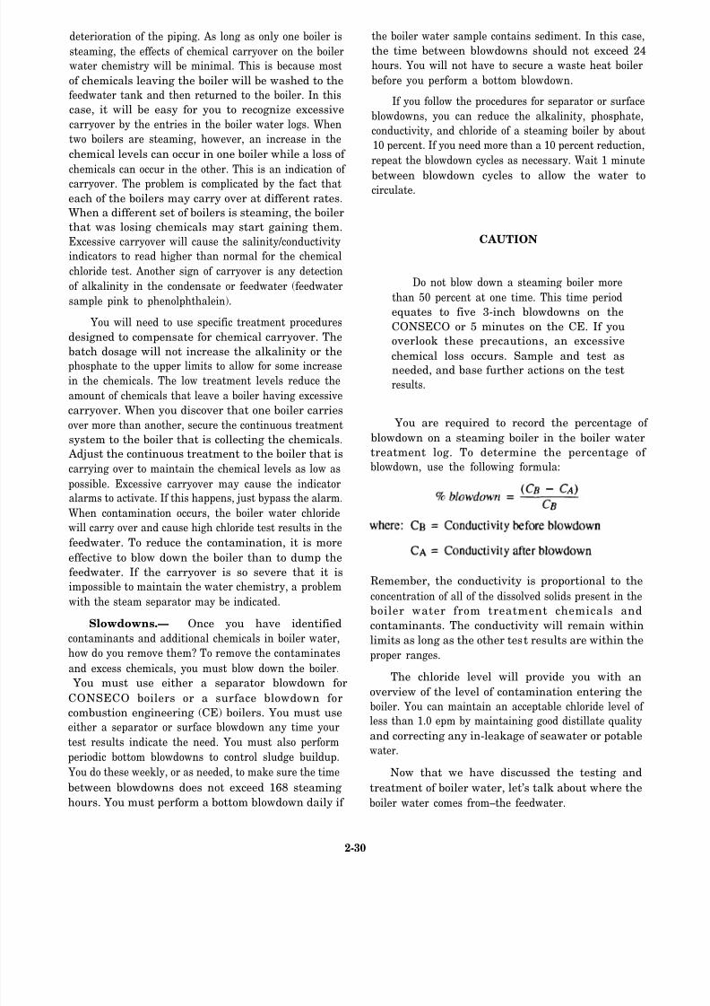
8/14/2019 US Navy Course NAVEDTRA 14115 - Gas Turbine Systems Technician Mechanical) 2
http://slidepdf.com/reader/full/us-navy-course-navedtra-14115-gas-turbine-systems-technician-mechanical 68/349
deterioration of the piping. As long as only one boiler is
steaming, the effects of chemical carryover on the boiler
water chemistry will be minimal. This is because most
of chemicals leaving the boiler will be washed to the
feedwater tank and then returned to the boiler. In this
case, it will be easy for you to recognize excessive
carryover by the entries in the boiler water logs. When
two boilers are steaming, however, an increase in the
chemical levels can occur in one boiler while a loss of
chemicals can occur in the other. This is an indication of
carryover. The problem is complicated by the fact that
each of the boilers may carry over at different rates.
When a different set of boilers is steaming, the boiler
that was losing chemicals may start gaining them.
Excessive carryover will cause the salinity/conductivity
indicators to read higher than normal for the chemical
chloride test. Another sign of carryover is any detection
of alkalinity in the condensate or feedwater (feedwater
sample pink to phenolphthalein).
You will need to use specific treatment procedures
designed to compensate for chemical carryover. The
batch dosage will not increase the alkalinity or thephosphate to the upper limits to allow for some increase
in the chemicals. The low treatment levels reduce the
amount of chemicals that leave a boiler having excessive
carryover. When you discover that one boiler carries
over more than another, secure the continuous treatment
system to the boiler that is collecting the chemicals.
Adjust the continuous treatment to the boiler that is
carrying over to maintain the chemical levels as low as
possible. Excessive carryover may cause the indicator
alarms to activate. If this happens, just bypass the alarm.
When contamination occurs, the boiler water chloride
will carry over and cause high chloride test results in thefeedwater. To reduce the contamination, it is more
effective to blow down the boiler than to dump the
feedwater. If the carryover is so severe that it is
impossible to maintain the water chemistry, a problem
with the steam separator may be indicated.
Slowdowns.— Once you have identified
contaminants and additional chemicals in boiler water,
how do you remove them? To remove the contaminates
and excess chemicals, you must blow down the boiler.
You must use either a separator blowdown for
CONSECO boilers or a surface blowdown for
combustion engineering (CE) boilers. You must use
either a separator or surface blowdown any time your
test results indicate the need. You must also perform
periodic bottom blowdowns to control sludge buildup.
You do these weekly, or as needed, to make sure the time
between blowdowns does not exceed 168 steaming
hours. You must perform a bottom blowdown daily if
the boiler water sample contains sediment. In this case,
the time between blowdowns should not exceed 24
hours. You will not have to secure a waste heat boiler
before you perform a bottom blowdown.
If you follow the procedures for separator or surface
blowdowns, you can reduce the alkalinity, phosphate,
conductivity, and chloride of a steaming boiler by about
10 percent. If you need more than a 10 percent reduction,
repeat the blowdown cycles as necessary. Wait 1 minute
between blowdown cycles to allow the water tocirculate.
CAUTION
Do not blow down a steaming boiler more
than 50 percent at one time. This time period
equates to five 3-inch blowdowns on the
CONSECO or 5 minutes on the CE. If you
overlook these precautions, an excessive
chemical loss occurs. Sample and test asneeded, and base further actions on the test
results.
You are required to record the percentage of
blowdown on a steaming boiler in the boiler water
treatment log. To determine the percentage of
blowdown, use the following formula:
Remember, the conductivity is proportional to the
concentration of all of the dissolved solids present in the
boiler water from treatment chemicals and
contaminants. The conductivity will remain within
limits as long as the other test results are within the
proper ranges.
The chloride level will provide you with an
overview of the level of contamination entering the
boiler. You can maintain an acceptable chloride level of less than 1.0 epm by maintaining good distillate quality
and correcting any in-leakage of seawater or potable
water.
Now that we have discussed the testing and
treatment of boiler water, let’s talk about where the
boiler water comes from–the feedwater.
2-30
8/14/2019 US Navy Course NAVEDTRA 14115 - Gas Turbine Systems Technician Mechanical) 2
http://slidepdf.com/reader/full/us-navy-course-navedtra-14115-gas-turbine-systems-technician-mechanical 69/349
Feedwater
Feedwater is extremely important to the overall
operation of the steam plant. After all, the feed tank is
where the water that supplies the boilers comes from and
where the water will return after it is condensed. This is
why the quality of your ship’s feedwater is so important.
The quality of feedwater can ultimately affect the
efficiency of your ship’s engineering equipment and
systems.In a properly operating waste heat boiler system, the
distillate (evaporator supply) contains the highest level
of contaminants. Therefore, the makeup feedwater rate
will determine the contaminate level that will enter the
boiler. High makeup rates will cause the boiler water
chloride and conductivity to increase. This condition
will lead to higher use of treatment chemicals. Both
conditions will cause greater sludge formations and an
increase in the deposits on the watersides. To keep the
makeup rate at a minimum, make sure all system leaks
are corrected. In a properly maintained system, the
makeup feedwater rate should be less than 900 gallons
per day.
CONTAMINANTS.— There are four primary
feedwater contaminants you will need to monitor: (1)
seawater, (2) shore water, (3) oil, and (4) dissolved
oxygen. In the following paragraphs, we will briefly
discuss the origin, detection methods, effects, and
corrective actions in regard to these contaminants.
Seawater.— Seawater is the most common
contaminant found in marine boiler water/feedwater
systems. The most routine source of intermittent
seawater contamination in feedwater is the distillers,
especially during start-up of the distillers.
Contamination from the distiller air ejector drains can
ultimately cause a rapid and large increase in boiler
water chloride. The source of this contamination, of
course, is from concentrated seawater, more commonly
called brine.
Another source of seawater contamination in
feedwater that will ultimately cause an increase in boiler
water chloride are leaks in the condensate system. Small
condenser leaks can cause a continual, low level
increase in boiler water chloride. Tube leaks in a
condensate cooler or control condenser can cause
varying levels of contamination, depending on the
amount of leak-by. The most common methods of
detection you can use are the salinity/conductivity
indicators or the chemical chloride test. You should
readily notice the effects of condensate system leaks on
the boiler water chemistry. There will be a noticeable
decrease in alkalinity and phosphate and usually a
somewhat large increase in conductivity and chloride.
You must locate, isolate, and correct the source of
the contamination. You must continue to monitor
(sample and test) the water, add chemicals, and blow
down as needed to maintain these contaminants within
their specified control limits. To remove high levels of
contamination, however, the most effective method you
can use is to secure, cool, dump, and flush the system.
Shore Water.— The second most common
contaminant is shore water. Shore water contamination
originates from a potable water supply from shore.
Shore water can enter the feedwater system through a
leaking steam coil in a hot water heater or by the use of
contaminated shore source feedwater or steam.
You can detect contaminated shore water by
monitoring the condensate cooler salinity indicator or
by performing a feedwater hardness test. By reviewing
the logs, you should also notice an effect on water
chemistry, as indicated by a decrease in phosphate and
increase in alkalinity. In most cases, you will also see an
increase in conductivity and chloride. The corrective
actions you should take are the same ones you should
take for seawater contamination.
Oil.— The third major contaminate is oil. Steam, as
well as feedwater, can become contaminated by oil if a
leak develops in either a fuel oil or lube oil heater. Oil
contamination can be indicated in the feedwater or
boiler water sight glass, in feedwater or boiler water
samples, or by oily condensate in the inspection tank.
The effect oil contamination can have on boiler water
chemistry is that it can induce carryover with no effecton alkalinity, phosphate, conductivity, or chloride. The
corrective actions you should take are to find, isolate,
and correct the source of the contamination. Surface
blow the CE boiler to remove the contamination. If the
boiler is steaming, treat the water as needed to keep the
alkalinity and phosphate levels within the limits. You
may have to secure, dump, and flush the boiler water to
remove the oil contamination. If contamination levels
are severe, clean the boiler with an alkaline boilout
according to the procedures in NSTM, chapter 221,
“Boilers.”
Dissolved Oxygen.— The last contaminant we will
discuss is dissolved oxygen. Dissolved oxygen in the
feedwater as it enters the boiler will cause corrosion of
the nonstainless-steel coils.
On the CE boilers and on some of the CONSECO
boilers, a DFT is installed to reduce the oxygen level and
minimize the corrosion rate. A DFT is not required on a
2-31

8/14/2019 US Navy Course NAVEDTRA 14115 - Gas Turbine Systems Technician Mechanical) 2
http://slidepdf.com/reader/full/us-navy-course-navedtra-14115-gas-turbine-systems-technician-mechanical 70/349
boiler that has stainless-steel coils. You will need to
check the DFT to make sure it is working properly. You
will use the feedwater dissolved oxygen test to detect a
malfunctioning DFT. In the case of a malfunctioning
DFT, you must find the cause of the malfunction and
have it corrected immediately. Dissolved oxygen
contamination can often be traced to the following
mechanical failures:
1.
2.
3.
4.
Improper operation of the DFT spray valves or
steam atomizing valve
Inadequate venting of the DFT
Excessive water level in the DFT, flooding the
steam atomizing valve
A fluctuating steam supply pressure as a result
of a malfunction of the steam control valve
CONTROL METHODS.— For a brief review of the
methods you should use for feedwater contamination
control, look again at the chart in table 2-1. Again, notice
that some of the test frequencies say “as required.” All
of these areas are monitored by an individual
salinity/conductivity indicator. The test frequency will
be based on the chemical test comparison results.
To perform salinity indicator comparison tests
correctly, there are two things you must keep in mind:
1.
2.
Do not perform a comparison test on a feedwater
tank sample within 1 hour of adding distillate to
the feed tank.
Do not perform comparison tests within 1 hour
after starting or securing a waste heat boils.
During start-up and securing, the water level inthe steam drum/separator will increase and
boiler water will overflow into the
steam/condensate system. This contamination
will cause the indicators to read higher than the
chemical chloride test.
Jacket Water
You must test the jacket water system for nitrite and
chloride concentration levels. For proper protection of
the jacket water cooling system, you should maintain the
nitrite (NO2) concentration level at a minimum of 1,000
ppm and the chloride level below 100 ppm. If the nitrite
level is below 1,000 ppm, the Nalcool 2000 will not
provide adequate corrosion protection. Chloride levels
above 100 ppm indicate that seawater has leaked into
the coding system. Another characteristic you should
know about seawater is that it contains “hardness.” The
hardness in seawater will cause scale formation on hot
metal surfaces in which the temperature is 130°F
(54.4°C) or above. In dealing with these characteristics,
let’s first briefly describe the test for chloride.
CHLORIDE TEST.— To perform the chloride test,
you should add two dippers of cupric sulfate to a 10 mL
sample of Nalcool 2000 treated coolant. Allow it to stand
until the sample is filtered. Then, immerse the end of a
quantab chloride test strip in the sample. After an
exposure period, remove the quantab and read the scale.
Use the conversion chart included in the quantab test
strip bottle to convert the scale reading to ppm chloride.
NITRITE TEST.— For the nitrite test, take 1 mL of
Nalcool treated coolant and dilute it with 100 mL of
distilled water. Dip a nitrite test strip into the diluted
sample. After a brief development time, compare the
color on the stick with the color chart on the side of the
test stick container to determine the nitrite content.
When chloride and nitrite tests are performed, there
are some important steps that are frequently overlooked.
You can avoid these mistakes by taking the following
precautions:
1.
2.
3.
4.
Always check the expiration date on the quantab
and nitrite test stick bottles. Do not use the test
sticks if the date has expired.
Do not try to use another quantab conversion
chart if the one for the bottle you are using is
missing. Because the quantabs are produced in
batches, the conversion chart with each quantab
bottle is specifically for use with the quantabs in
that bottle.
Always keep the quantab and nitrite test stickbottles tightly closed when they are stored.
Never immerse the entire quantab test strip
beneath the level of the solution you are testing;
otherwise, the test will give you a false low
result.
By taking these precautions and preforming the tests
correctly, you can obtain reliable test results that will
help you monitor and maintain the jacket water system.
Waste Heat Water
The nitrite test is the only test you will need for the
waste heat water system. To perform this test, dip a
nitrite test stick directly into a sample of waste heat
water. After a brief development time, compare the color
on the stick to the color chart on the container to
determine the nitrite concentration level. Ideally, the
nitrite concentration should he zero. From time to time,
2-32

8/14/2019 US Navy Course NAVEDTRA 14115 - Gas Turbine Systems Technician Mechanical) 2
http://slidepdf.com/reader/full/us-navy-course-navedtra-14115-gas-turbine-systems-technician-mechanical 71/349
Fi gure 2 -13 .—Suggested fuel managem ent log.
however, leaks can develop in the waste heat
exchanger and jacket water will enter the waste heatwater system. If a leak develops, you must have itrepaired as soon as possible. The nitrite concentration
level must not exceed 25 ppm for any reason. There isa good reason for this concern. Both nitrites and
berates are poisonous. Both of these toxins couldenter the ship’s potable water system through the
heat exchangers of the distillers.
To summarize, we have discussed the basic
procedures you should use to sample, test, andanalyze the quality of the fuels, oils, and watersupplies received, stored, and prepared for use aboard
your ship. In the next section, we will tell you aboutsome of the responsibilities you will have for
documenting the quality of these important supplies.
LOGS AND RECORDS
The logs and records you will maintain in the oil
lab are apart of the Navy’s record system. Thissystem will help you improve your record keeping
through standardization, automation, speed, andefficiency.
Accurate, legible, and up-to-date logs and recordsplus the timely submission of accurate and legible
reports reflect efficient administration of the oillaboratory. Remember, the logs and recordsmaintained by the oil laboratory provide the data for
engineering reports to higher authority. Reviewing
the logs, records, and reports will allow the engineerofficer an easy and effective method of keeping
informed of the state of the equipment in thedepartment.
Proper administration of the oil laboratory logs,records, and reports system requires the regular and
conscientious attention of all oil lab personnel. Theperson filling out the log or record must haveknowledge of both the material recorded or reported
and the correct method of documentation. Yourengineer officer has a record reference file containing
complete information on the methods of maintainingthese important records.
FUEL OIL TEST LOGS
Stringent fuel quality requirements protect gasturbine engines from serious damage, such as
corrosion of the gas turbine hot section, fouling of
engine controls, and plugging of fuel nozzles.Maintaining a fuel oil (FO) test log system helps the
engineering department to achieve theserequirements.
Fuel Managem en t Log
An example of a fuel management log is shown inf igure 2-13. This log is a locally prepared document
that
2-33

8/14/2019 US Navy Course NAVEDTRA 14115 - Gas Turbine Systems Technician Mechanical) 2
http://slidepdf.com/reader/full/us-navy-course-navedtra-14115-gas-turbine-systems-technician-mechanical 72/349
includes spaces for recording the results of all shipboard
fuel tests. Whenever test results exceed maximum
control limits, the entries should include notations that
corrective actions have been taken.
The fuel management log should include the
following important categories:
1.
2.
3.
4.
5.
A sequential listing of sample analyses, in-
cluding:
a. visual inspections,
b. shipboard analyses, and
c. laboratory analyses.
An operational procedures check-off list
Centrifugal purifier cleaning actions
Prefilter and filter/separator replacement actions
Tank inspections and findings
The information in the fuel management log serves
as an important part of shipboard maintenance. It aids
in the prevention of delivery of contaminated fuel to the
gas turbine engines.
JP-5 Fuel Sample Log
Since most gas turbine ships can support
helicopters, an aviation fuel (JP-5) system is installed.
As we mentioned earlier, fuel quality requirements are
more critical and extensive for JP-5 fuel than for other
fuels. Minute amounts of dirt and water in the fuel cancause engine failures. To monitor for these conditions,
the oil lab should maintain a fuel sample log. This log
must include a sequential listing of samples submitted
for testing and the results of the tests as they are reported
by the testing laboratory. The oil lab should include the
following information in the JP-5 sample log:
Identification of the ship submitting the sample
(name and hull number)
Type of fuel
Date the sample is drawn
Name of the person drawing the sample
Fueling station number or filter/separator
sampled
Heading: Aviation Fuel Sample – Sediment and
Flash Point
The oil lab will use the fuel sample log in a continuing
shipboard QA program to document the ship’s QA
efforts.
LUBE OIL TEST LOGS
Because of the importance of good quality
lubricating oil, the Lube Oil Management Program was
developed. The guidelines for this program are
presented in the form of an instruction. Although this
instruction may vary somewhat in the procedures it
includes, the goals are the same. To accomplish these
goals, gas turbine ships must maintain lubricating oil
(LO) logs.
Samples of lubricating oil should be taken at
definite intervals to determine whether the oil meets all
requirements. The results of the samples must be entered
in the proper log as specified in the Lube Oil
Management Program.
Naval Oil Analysis Program Logs
The Naval Oil Analysis Program (NOAP) was
developed for off-ship analysis. Under the computerized
NOAP, special oil sampling techniques, sample
equipment, sample markings, and shipping instructions
are prescribed for shipboard machinery systems
assigned to this program. All NOAP oil samples must
be handled exactly as prescribed in the existing NOAP
directives. These directives can be found in your current
type commander’s instructions.
Diesel Oil Log
For each shipboard diesel engine, the viscosity and
reaction (acidity) test results must be recorded in the
diesel engine oil test log, such as the one shown in figure
2-14. The oil lab must maintain a separate oil test log for
each shipboard diesel engine.
WATER TREATMENT LOGS
The importance of maintaining accurate boilerwater and feedwater chemistry logs and records must
not be underestimated. The engineer officer and his or
her assistants use the data reflected in these logs to
measure the performance, stability, efficiency, and state
of material readiness of the engineering plant.
Remember, the decision-making process involved in an
effective water chemistry program aboard your ship will
be supported by the information in these logs.
2-34

8/14/2019 US Navy Course NAVEDTRA 14115 - Gas Turbine Systems Technician Mechanical) 2
http://slidepdf.com/reader/full/us-navy-course-navedtra-14115-gas-turbine-systems-technician-mechanical 73/349
Fi gure 2-14 .—Diesel Engine Lube Oil Testing Log.
The engineering department of your ship will needboth the engineer officer and the commanding officer,
specific data to maintain the proper water conditionsin the waste heat steam plant. The three logs you will
use to record and maintain these data are:
1. Cover Sheet and Monthly Boiler Data Log 2. Feedwater Chemistry Worksheet/Log
3. Waste Heat Boiler Water Chemistry
Worksheet/Log
4. Reserve/Makeup Feedwater Tests Log
5. Fuel and Water Report
6. Boiler Water/Feedwater Test and Treatment
Chemical Inventory Log
To be an effective engineer, you should be familiarwith the purpose, content, and general procedures for
each of these logs. Let’s take a brief look at each of them.
Cover She et and Monthly Boiler Data Log
You must prepare a cover sheet and MonthlyBoiler Data log sheet, such as the one shown in figure
2-15. Notice in view A that the log contains the
signatures of verifying they have reviewed thepackage. On the reverse side of the cover sheet (viewB) are the proper data entries for the boiler. These
entries include information such as total steaminghours, safety valve settings, and water chemistry
standards.
Feedwate r Chem istry Workshee t/ Log
The Feedwater Chemistry Worksheet/Log contains
the daily chemical condition of the waste heat boilerfeedwater system. The information you will record in
this log includes the results of chemical tests, salinityindicator comparisons, shore steam and shorefeedwater chemical test data, and remarks.
A sample of the Feedwater Chemist
Worksheet/Log is shown in figure 2-16. Notice thatthe data entries are made on the front side (view A)and the section for remarks is on the reverse side
(view B).
You must start a Feedwater ChemistWorksheet/Log daily for each feedwater andcondensate system in operation. A daily log is not
needed, however, for a system that is not inoperation. In this case, just use
2-35

8/14/2019 US Navy Course NAVEDTRA 14115 - Gas Turbine Systems Technician Mechanical) 2
http://slidepdf.com/reader/full/us-navy-course-navedtra-14115-gas-turbine-systems-technician-mechanical 74/349
2-36

8/14/2019 US Navy Course NAVEDTRA 14115 - Gas Turbine Systems Technician Mechanical) 2
http://slidepdf.com/reader/full/us-navy-course-navedtra-14115-gas-turbine-systems-technician-mechanical 75/349
Figure 2-16.—Feedwater Chemistry Worksheet/Log.
2-37

8/14/2019 US Navy Course NAVEDTRA 14115 - Gas Turbine Systems Technician Mechanical) 2
http://slidepdf.com/reader/full/us-navy-course-navedtra-14115-gas-turbine-systems-technician-mechanical 76/349
Figure 2-17.—Waste Heat Boiler Water Chemistry Worksheet/Log.
2-38
8/14/2019 US Navy Course NAVEDTRA 14115 - Gas Turbine Systems Technician Mechanical) 2
http://slidepdf.com/reader/full/us-navy-course-navedtra-14115-gas-turbine-systems-technician-mechanical 77/349
the front of a single log sheet to record the dates that
testing was not needed. You should also include a
remark stating why testing was not necessary.
Waste Heat Boiler Water Chemistry
Worksheet/Log
The Waste Heat Boiler Water Chemistry
Worksheet/Log is started daily and should contain any
significant event or action that took place in regard to
the waste heat boilers.
A sample of a Waste Heat Boiler Water Chemistry
Worksheet/Log is shown in figure 2-17. Notice in views
A and B that both the front and back sides of this log
contain sections for data on chemical test results, chemical
treatments, blowdowns, steaming hours, and remarks.
Reserve/Makeup Feedwater
Tests Log
A sample of the Reserve/Makeup Feedwater Tests
Log is shown in figure 2-18. The front and back of this
log, displayed in views A and B, contain sections for
chemical test results for salinity indicator
comparisons and shore source feedwater (steam
condensate or processed feedwater) quality. This log
is normally prepared daily unless all of the feedwater
tanks are empty. If all of the tanks are empty and no
testing is required, enter the inclusive dates on the
front of the log and give the reason in the remarks
section.
Fuel and Water Report
The Fuel and Water Report, shown in figure
2-19, is a daily report of the fuel and water status
the oil lab must prepare to reflect these conditions
at 0000 hours. The commanding officer receives
this report daily. The report contains data, such as
total fuel and lube oil on board and the amount of
potable water and reserve feedwater on board. TheFuel and Water Report also includes the previous
day’s feedwater and potable water consumption
figures and the results of the water tests. The
officer of the deck (OOD) receives the original
copy in time for submission to the commanding
officer or command duty officer with the 12
o’clock reports. The OOD retains the copy.
Boiler Water/Feedwater Test and Treatment
Chemical Inventory Log
The Boiler Water/Feedwater Test and
Treatment Chemical Inventory Log shown in figure
2-20 provides a record and monthly inventory of
test and treatment chemicals. As shown in views A
and B of the log, each standard, treatment
chemical, and stock chemical must be accounted
for monthly. This log, when properly maintained,is a valuable asset the oil lab can use to keep the
test and treatment chemical stocks properly rotated
and as fresh as possible.
Jacket Water Log
An example of a Diesel Engine Jacket Cooling
Water System/Treatment Log is shown in figure 2-21.
As shown in views A and B, you will use both the front
and the back to record data.
This is a monthly log, consisting of the following
sections:
1. Chemical Test Results: You must maintain this
section on a 2400-hour clock basis. You should enter the
date and time for the following actions:
a.
b.
c.
d.
e.
Completion of jacket water sampling
Completion of draining a portion of jacket
water
Completion of dumping the entire jacket
water system
Completion of freshly filling
Completion of water additions
Make sure you use the appropriate codes listed on the
back of the log for all entries. Both the tester and the
EOOW/EDO must enter their initials when the tests are
completed.
2. Chemical Treatment: Make appropriate entries
for the following information:
a. Amount of Nalcool 2000 required
b. Date and time of completion of the chemicaladdition
Circle all out-of-limits readings. Make sure the person
who performed the chemical treatment calculations has
initialed the results.
3. Remarks:
significant events
This section should describe
related to the jacket cooling water
2-39

8/14/2019 US Navy Course NAVEDTRA 14115 - Gas Turbine Systems Technician Mechanical) 2
http://slidepdf.com/reader/full/us-navy-course-navedtra-14115-gas-turbine-systems-technician-mechanical 78/349
Figure 2-18.—Reserve/Makeup Feedwater Tests Log.
2-40

8/14/2019 US Navy Course NAVEDTRA 14115 - Gas Turbine Systems Technician Mechanical) 2
http://slidepdf.com/reader/full/us-navy-course-navedtra-14115-gas-turbine-systems-technician-mechanical 79/349
Figure 2-19.—Fuel and Water Report.
system of that particular diesel engine. You may need
to insert additional pages for remarks. Make sure allremarks are accompanied by the date and time. If you
have a doubt whether or not you should make acertain entry, go ahead and enter it. You should
record the following types of information: a. The reasons for out-of-limits conditions and the
actions taken to correct the problem b. The source of water used for filling or topping off
the cooling system
c. The reason for partially draining or dumping acooling system
The LCPO/MPA must review and initial this log.
The log must then be reviewed and signed by theengineer officer.
Waste Heat Water Log
This locally prepared log is recommended, but it isnot required by NAVSEA. Remember, although a log
is not required by NAVSEA, your ship or typecommander may have different requirements. Even ifyou do not use a log, the test results must still be
entered in the engineering log.
2-41

8/14/2019 US Navy Course NAVEDTRA 14115 - Gas Turbine Systems Technician Mechanical) 2
http://slidepdf.com/reader/full/us-navy-course-navedtra-14115-gas-turbine-systems-technician-mechanical 80/349
Figure 2-20.—Boiler Water/Feedwater Test and Treatment Inventory Log.
2-42

8/14/2019 US Navy Course NAVEDTRA 14115 - Gas Turbine Systems Technician Mechanical) 2
http://slidepdf.com/reader/full/us-navy-course-navedtra-14115-gas-turbine-systems-technician-mechanical 81/349
Fi gure 2-21 .—Diesel Engine Jacket Cooling Water System Nalcool 2000 Treatment Log.
SUMMARY
As an oil king, you will be responsible for one of the most important operations in the engineeringdepartment, the maintenance of the fuels and
lubricating oils. This chapter has pointed out theimportance of having clean fuel reach the gas turbine
engines and the necessity of maintaining a highquality lubricating oil product. The knowledge yougained from this chapter concerning safety, test
requirements, and record keeping should provide youwith a foundation you can use to ensure the sound
operation of the propulsion plant.
This also holds true if you are assigned waste heatboilers (WHBs) or diesel generators. The proper
testing and treatment of the WHBs and SSDGs willensure their proper operation and provide for alonger life-span for the equipment. As a GSM
assigned to the oil lab, you hold an important andnecessary job within the engineering department
structure.
2-43

8/14/2019 US Navy Course NAVEDTRA 14115 - Gas Turbine Systems Technician Mechanical) 2
http://slidepdf.com/reader/full/us-navy-course-navedtra-14115-gas-turbine-systems-technician-mechanical 82/349

8/14/2019 US Navy Course NAVEDTRA 14115 - Gas Turbine Systems Technician Mechanical) 2
http://slidepdf.com/reader/full/us-navy-course-navedtra-14115-gas-turbine-systems-technician-mechanical 83/349
CHAPTER 3
ENGINEERING CONTROL SYSTEM OPERATION
One of the most remarkable design features of a gas
turbine-powered ship is that the engineering plant can
be controlled from a central area located away from the
actual equipment and systems. This central location,
known as the central control station (CCS), is your ship’s
primary control watch station for operating nearly all the
equipment in the engineering plant. Any of your ship’s
engineering systems that are not controlled in the CCS
can at least be monitored there. The CCS system not
only allows for efficient watch standing but also permits
the engineering officer of the watch (EOOW) and the
propulsion, electrical, and damage control watch
standers of your ship to have a quicker and more
comprehensive look at the vital parameters of all
engineering equipment and systems. In all gas
turbine-powered ships, the foundation of the CCS is the
engineering control system.
The engineering control systems on gas
turbine-powered ships come in three major designs. The
design of the control system is based on the class of ship.
The DD-963, DDG-993, and CG-47 class ships use the
engineering control and surveillance system (ECSS) to
operate their gas turbine equipment. The FFG-7 class
ships use the engineering plant control system (EPCS)
to both operate and monitor their gas turbine equipment.
The relatively new DDG-51 class ships use the
machinery control system (MCS) to both control and
monitor their gas turbine equipment. In your career as a
GSM, you may not be directly involved with all of these
control systems. You should, however, be aware of each
of these systems and how they relate to the engineering
plant. Of course, as you advance in the GS rating, you
should also be aware of certain watch-standing
requirements associated with these systems.
After reading this chapter, you should have a good
understanding of the function and operation of the three
major engineering control systems used on gas
turbine-powered ships. You should also be able to
discuss how each of these control systems interacts with
the equipment and systems of the ship’s engineeringplant. Although you may not work on all these systems,
the knowledge you gain from this chapter should help
you to both study for advancement and prepare for your
watch-standing qualifications as you become senior in
the GS rating.
Remember, the information in this chapter is
intended for training and advancement study only. It is
not intended to replace the engineering operational
sequencing system (EOSS) or the appropriate technical
manuals for your ship’s equipment and systems. In this
chapter, we will provide you with an overview of the
consoles of the three major engineering control systems
used on gas turbine-powered ships. We will not discuss
these consoles in depth. For a detailed description, we
recommend you review Gas Turb ine Sys tems
Technician (Electrical) 3/ Gas Turbine System s
Technician (Mechanical) 3, Volume 2, NAVEDTRA
10564.
CENTRAL CONTROL STATIONOPERATIONS
In all gas turbine-powered ships, the CCS is the
main operating station from which the engineering plant
can be monitored and controlled. The specific control
consoles located in the CCS will vary, however,
depending on the class of ship. On the DD-963,
DDG-993, and CG-47 class ships, the propulsion and
auxiliary control console (PACC), electric plant control
console (EPCC), fuel system control console (FSCC),
and damage control console (DCC) are located in the
CCS. On the DDG-51 class ships, the PACC, EPCC,
engineering officer of the watch/logging unit(EOOW/LU), and DCC are located in the CCS. On the
FFG-7 class ships, the propulsion control console
(PCC), EPCC, auxiliary control console (ACC), and
DCC are located in the CCS. In this chapter, we will
briefly discuss some basic operations performed from
the major control consoles located in the CCS. We will
begin our discussion with the CCS control consoles
found on the DD-963, DDG-993, and CG-47 class ships.
Next, we will describe those found on the DDG-51 class
ships. Last, we will talk about the ones on the FFG-7
class ships. We will provide you with a fundamental
overview of these consoles. For a detailed descriptionof operating procedures for specific control consoles,
we recommend you refer to the EOSS, engineering
operational procedures (EOP), and appropriate
technical manuals for your ship’s equipment and
systems.
3-1

8/14/2019 US Navy Course NAVEDTRA 14115 - Gas Turbine Systems Technician Mechanical) 2
http://slidepdf.com/reader/full/us-navy-course-navedtra-14115-gas-turbine-systems-technician-mechanical 84/349
Figure 3-1.—PACC layout.
DD-963, DDG-993, AND CG-47 CLASS
CCS OPERATIONS
On DD-963, DDG-993, and CG-47 class ships, the
CCS is located remotely from the ship’s machinery
spaces. This design allows the engineering plant to be
monitored and controlled with a minimum of personnel.
The two major consoles that control the engineering
plants on these ships are the PACC and the EPCC. The
PACC is the console in the ECSS where control of thepropulsion plant and auxiliary systems is normally
located. The EPCC is the console where control of the
electric plant is normally located. On the CG-47 class
ships, the EPCC also controls and monitors the
distribution of the ship’s 400-Hz power. We will briefly
discuss the operation of these two consoles in the
following paragraphs.
PACC
The PACC is the central control point in thepropulsion plant’s control system. The PACC monitors
and controls the operation and performance of the ship’s
main propulsion equipment and systems by sending
commands that will operate specific controls to
sequence the operation of equipment or control
subsystem operation.
The PACC contains electrical equipment that is
capable of controlling and monitoring both propulsion
plants and most of the ship’s auxiliary systems. Notice
in figure 3-1 how each panel of the PACC is dedicated
to particular types of control and monitoring. In this
section, we will briefly discuss the following control and
monitoring systems that are operated from the PACC:
1.
2.
3.
4.
5.
6.
7.
8.
Fuel oil service system
Lube oil system
Air system
Gas turbine module (GTM) control
Engine order telegraph (EOT) control
Throttle and pitch
Plant mode
Auxiliaries
In the following paragraphs, we will provide a basic
overview of these systems. For detailed information,
consult the appropriate EOSS, EOP, and technicalmanuals.
Fuel Oil Service System
For the fuel oil service system, the control and
monitoring functions at the PACC can be divided into
3-2

8/14/2019 US Navy Course NAVEDTRA 14115 - Gas Turbine Systems Technician Mechanical) 2
http://slidepdf.com/reader/full/us-navy-course-navedtra-14115-gas-turbine-systems-technician-mechanical 85/349
two major categories: (1) fuel oil service control and
monitoring, and (2) GTM control and monitoring.
Together they function to deliver fuel oil at the proper
pressure and temperature to the individual propulsion
gas turbines. In the following paragraphs, we will
describe the monitoring and control functions available
at the PACC for these two categories. Let’s first talk
about those for the fuel oil service.
FUEL OIL SERVICE.— For fuel oil service
monitoring and control, the following nine functions are
available at the PACC:
1.
2.
3.
4.
5.
6.
7.
8.
9.
Fuel oil service tanks A/B temperature
monitoring
Fuel oil service tank suction and recirculating
valves control and monitoring
Fuel oil service booster pump A and B control
and monitoring
Prefilter differential pressure monitoring
(CG-47 class only)
Header pressure and temperature monitoring
Heater temperature monitoring
Coalescer filter monitoring
Leak detection tank monitoring
Suction strainer differential pressure monitoring
For all nine functions, monitoring is continuously
available at both the PACC and the propulsion local
control console (PLCC), but control is available only at
one console at a time.
At the PACC, control of the fuel oil service system
consists of remote manual control of the suction and
recirculating valves in the two service tanks and remote
automatic or manual control of the two fuel oil service
pumps. For valve control, the PACC sends open or close
commands to the valve motor controllers. Because both
valves in a service tank must be in the same state (either
open or closed) to operate properly, the PACC can send
these commands simultaneously to both the suction and
the recirculating valves. For service tank control,
separate control switches at the PACC allow the
operator to control each service tank independently. Atthe PACC, service tank monitoring consists of tank
temperature high and low alarms.
From the PACC, the operator can operate the two
fuel oil service pumps in either the manual or automatic
control mode. By setting the pump mode switch to
MANUAL, the operator can control each of the pumps
individually by using the push buttons on the PACC.
Setting the pump mode switch to either the A LEAD or
B LEAD position sets up the automatic control circuits,
allowing the operator to select a lead pump and a standby
pump. From this point, pump control becomes a
function of header pressure and time.
GTE FUEL OIL SERVICE.— For gas turbine
engine (GTE) fuel oil monitoring and control, the
following five functions are available at the PACC:
1.
2.
3.
4.
5.
Supply temperature monitoring
Fuel purge control
Fuel filter monitoring
Main fuel valves control and monitoring
Emergency trip fuel valve control
The primary function of the GTE fuel oil controls
available at the PACC is to control the GTE fuel
shutdown valves and the emergency trip valves. Some
controls are also provided for fuel purging. By closing
either of the two main fuel valves, the operator can
prevent fuel from flowing to the engine fuel manifold.The operator’s control of these valves, however,
depends on whether the GTE control mode is manual,
manual initiate, or auto initiate. With the GTE in the
manual control mode, the operator can use the
push-button indicator on the PACC to generate main
fuel valve control signals to the freestanding electronics
enclosure (FSEE). With the GTE in either the manual
initiate or auto initiate control mode, the fuel valve
control signals are automatically generated by the
start/stop sequence control logic.
The other GTE fuel oil controls at the PACC arerelated to fuel purging operations. A common condition
requiring fuel purging is when an engine has been shut
down for over 15 days. The fuel will likely have to be
purged before the engine is started. This can be done by
motoring the GTE with the fuel purge valve open. At the
PACC, the operator opens the fuel purge valve by
depressing the FUEL PURGE ON push button. This
allows the fuel oil to flow through the engine fuel lines
and into the leak detection tank. In fact, the only way the
fuel valve can open is if an operator pushes the FUEL
PURGE ON push button at either the PACC or PLCC.
Now that we have described the fuel oil service
controls located at the PACC, let’s talk about the controls
for the lube oil system.
Lube Oil System
Each main engine room (MER) has its own separate
and independent lube oil system that can be monitored
and controlled from the PACC. Monitoring is available
3-3

8/14/2019 US Navy Course NAVEDTRA 14115 - Gas Turbine Systems Technician Mechanical) 2
http://slidepdf.com/reader/full/us-navy-course-navedtra-14115-gas-turbine-systems-technician-mechanical 86/349
continuously at both the PACC and the PLCC, but
control is available only at one of the consoles at a time.
At the PACC, lube oil control consists of either manual
or automatic control of the two lube oil service pumps.
The function of these pumps is to provide additional oil
to the lube oil pump that is attached to the main reduction
gear.
For the operator to be able to enable the pump
controls at the PACC, the local control switches on the
pumps must be in the REMOTE position. Then, the
operator can obtain individual manual control of each
of the two pumps by using the three push-button
indicators on the PACC. Setting the pump mode
auto/manual logic switch to MANUAL allows the
operator to control pump speed. When the operator
depresses the push-button indicator at the PACC, the
associated command goes to the PLCC circuitry and
then to the pump motor controller. Setting the pump
mode switch to either the A LEAD or B LEAD position
sets up the automatic control circuits, allowing the
operator to select a lead pump and a standby pump. Fromthis point, pump control becomes a function of header
pressure and time.
Lube oil control can be transferred from the PLCC
to the PACC by depressing the control transfer switch
at the PLCC. Then, the control commands can go from
the PACC over the serial data bus to the PLCC. The
PLCC pump control circuitry then initiates the proper
signals to the pump motor controllers.
Air System
There are two main air systems associated with theGTMs and the gas turbine generator sets (GTGSs): (1)
the bleed air system, and (2) the high-pressure air
system. These two air systems are interconnected by
piping and valves. Both systems are monitored and
controlled at the PACC. Control for both systems is
available continuously and simultaneously at both the
PACC and the PLCC. Let’s now look at each of these
systems separately, starting with the bleed air system.
BLEED AIR SYSTEM.— There is a separate bleed
air line to each GTM. Located in each of these lines is a
motor-operated bleed air valve. The position of the valvecan be controlled manually at the PACC as long as GTM
control is transferred to the PACC. The valve can also
be controlled automatically by the start/stop sequence
logic circuits. The status indicator lights on the PACC
will show the position of each bleed air valve.
The GTGS No. 3 has a bleed air isolate valve that
can isolate the GTGs No. 3 bleed air from the rest of the
ship’s bleed air system. The ISOLATE push button,
located on the PACC, will illuminate when the valve is
closed and the No. 3 GTGS has been isolated. On the
CC-47 class ships, the GTGS solenoid-operated bleed
air valves can be controlled from a bleed air valve
control panel next to the EPCC in the CCS.
Now let’s examine the bleed air system in terms of
its four distinct subsystems:
1. Starter air2. Masker air
3. Prairie air
4. Anti-icing air
We will briefly discuss each of these subsystems in the
following paragraphs.
Starter Air System.— The starter air system has
three operating modes available at the PACC: (1)
normal, (2) emergency, and (3) motor. Let’s first look at
the normal start air mode.
Normal start air is used during a normal start
sequence. The start air for the GTM is controlled by the
motor air regulator valve. This valve is controllable at
the PACC and can provide either one of two functions:
a valve-opened, nonregulated (start) position or a
valve-opened, regulated at 22 psi (motoring) position.
In the GTM, the last valve in the start air flow is the
starter air valve. The operator at the PACC can control
this valve either manually or automatically as long as
GTM control has been transferred to the PACC. The last
valve in the GTGS start air flow is through one of the
two starter air valves, either high pressure or lowpressure, depending on which is selected. Once the
valve is selected, then the start air control is maintained
by the GTGS’s system throughout the start sequence.
The operator at the PACC can start the emergency
start air by depressing the EMERGENCY push button.
This action allows air from the high-pressure storage
flasks to be made available for GTM starts. The
exception to this is in the case of the DDG-993 class
ships, which do not have a high-pressure/low-pressure
(HP/LP) air reducing station for GTM starting. The
high-pressure air is reduced and enters the GTM start airsystem upstream of the motor air regulator valve.
Masker Air System.— The operator can align the
masker air system from the PACC. The masker air
system causes the valves of the start air system to line
up to either one of two possible positions, depending
upon whether the masker air is ON or OFF and whether
the air system is in the automatic control mode. With the
3-4
8/14/2019 US Navy Course NAVEDTRA 14115 - Gas Turbine Systems Technician Mechanical) 2
http://slidepdf.com/reader/full/us-navy-course-navedtra-14115-gas-turbine-systems-technician-mechanical 87/349
masker air ON after a start sequence, the start air system
valves will automatically align to allow masker air to
flow to the masker air belts. With the masker air in the
OFF condition after a start sequence, the masker transfer
valve will remain in the start position. The operator can
perform both of these valve alignments manually from
the PACC.
Prairie Air System.— The prairie air system consists
of the prairie air supply valve. At the PACC, the operator
can use the ON/OFF push-button indicator to operate
and control prairie air in both engine rooms. If one of
the prairie supply valves should fail to respond to a
command, both sections of the push-button indicator
will fail to illuminate.
Anti-Icing Air System.— The anti-icing air system
includes a bleed air injection system and an electrical
intake heater system. For both the GTMs and GTGSs,
the bleed air injection system is used to increase the
intake combustion air temperature. The electrical heater
in this system is used to prevent ice formation of the
stack intake louvers and the blow-in doors. For the
operator at the PACC to be able to use the pushbuttons
to control the heaters, the intake heater controllers must
be in the ON position.
For each GTM and GTGS, monitoring for the bleed
air injection system and the anti-icing system is
available at the PACC. The operator at the PACC can
control the bleed air injection system manually.
High-Pressure Air System.— The high-pressure air
system is used for emergency starting of the gas turbine
generators (GTGs) and the main propulsion GTEsthrough an HP/LP air reducing station (except on
DDG-993 class ships). It is also the primary means to
start the first GTG, because bleed air is not available.
The two HP air compressors provide the system air to
the five air flasks in each MER and to the four air flasks
in the No. 3 GTG room.
GTM Control System
Most of the GTM control and monitoring circuitry
is used primarily for normal start-up and shutdown of
the propulsion gas turbines. All four GTM control andmonitoring functions can be accomplished at the PACC.
At the PACC, there are three possible start/stop modes
for each GTM: (1) manual, (2) manual initiate, and (3)
auto initiate. We will describe the auto initiate mode in
the plant mode control section of this chapter. For now,
let’s take a brief look at the manual and manual initiate
modes.
In the manual mode, the operator must generate the
start or stop commands at every step of the sequence.
This means the operator must make sure each step is
accomplished at the proper time. The sequencing of
these manual controls is the same as those shown in the
time sequential flow charts found in the EOSS and
appropriate technical manuals.
In the manual initiate mode, the starting and
stopping of the GTE is in a semiautomatic mode. In this
mode, the engine will start up or shut down
automatically. The control electronics at the PLCC will
automatically sequence the required start-up and
shutdown steps. This mode is semiautomatic because
operation of the brake and clutch (the brake only on the
CG-47 class ships) must be done manually. Now, let’s
shift from the GTM control system and take a look at
the EOT control system.
EOT Control System
The EOT control system controls the rpm and pitch
signals for both engine rooms. This system is used when
the PACC is in control of the throttles.
To generate propulsion command information, the
ECSS uses the three following types of EOTs:
1. Standard order–EOTs consisting of standard
engine commands, such as 2/3 back, 1/3 back, stop, 1/3
ahead, 2/3 ahead, and so forth
2. Digitized–An EOT system that provides rpm
commands to 0 to 200 rpm in 1-rpm increments and
pitch commands of -50 to +100 percent in 1-percent
increments
3. Plant mode–EOTs consisting of commands for
secured, split-plant, and full-power operations
These three EOT’s are at the SCC and the PACC. All
three communicate via the command and control serial
data bus.
STANDARD ORDERS.— For standard orders, the
operator initiates the commands at the SCC by moving
the integrated throttle control (ITC) lever to the standard
order position and depressing the stand order ALERT
push button. This sends the order to the PACC and the
PLCC for that particular shaft. If the PACC has control,
the operator can acknowledge the order by using either
one of the two following procedures:
1. Pushing the STD ORDER switch indicator,
which silences the EOT bell, and moving the ITC to
match the command from the bridge, as displayed by the
3-5
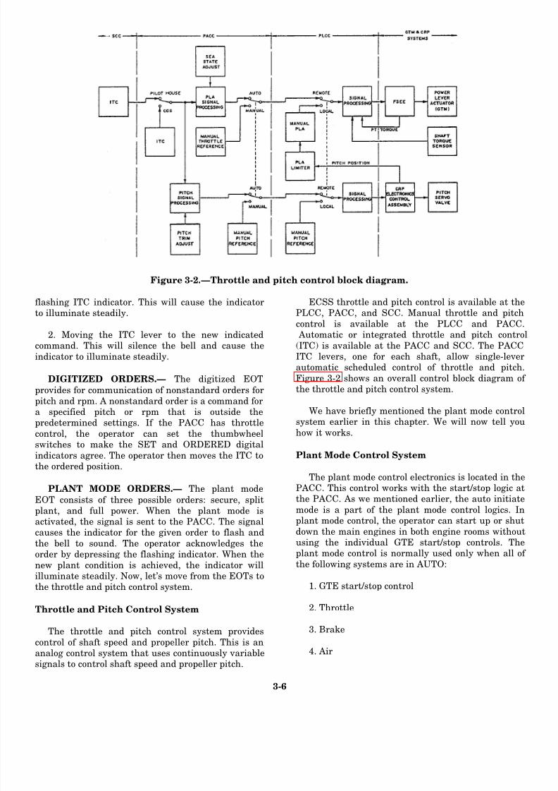
8/14/2019 US Navy Course NAVEDTRA 14115 - Gas Turbine Systems Technician Mechanical) 2
http://slidepdf.com/reader/full/us-navy-course-navedtra-14115-gas-turbine-systems-technician-mechanical 88/349
Figure 3-2.—Throttle and pitch control block diagram.
flashing ITC indicator. This will cause the indicatorto illuminate steadily.
2. Moving the ITC lever to the new indicatedcommand. This will silence the bell and cause the
indicator to illuminate steadily.
DIGITIZED ORDERS.— The digitized EOT
provides for communication of nonstandard orders for
pitch and rpm. A nonstandard order is a command for
a specified pitch or rpm that is outside thepredetermined settings. If the PACC has throttle
control, the operator can set the thumbwheelswitches to make the SET and ORDERED digital
indicators agree. The operator then moves the ITC tothe ordered position.
PLANT MODE ORDERS.— The plant mode
EOT consists of three possible orders: secure, split
plant, and full power. When the plant mode isactivated, the signal is sent to the PACC. The signalcauses the indicator for the given order to flash and
the bell to sound. The operator acknowledges the
order by depressing the flashing indicator. When thenew plant condition is achieved, the indicator willilluminate steadily. Now, let’s move from the EOTs tothe throttle and pitch control system.
Throttle and Pitch Control System
The throttle and pitch control system provides
control of shaft speed and propeller pitch. This is ananalog control system that uses continuously variablesignals to control shaft speed and propeller pitch.
ECSS throttle and pitch control is available at thePLCC, PACC, and SCC. Manual throttle and pitch
control is available at the PLCC and PACC. Automatic or integrated throttle and pitch contro
(ITC) is available at the PACC and SCC. The PACCITC levers, one for each shaft, allow single-leverautomatic scheduled control of throttle and pitch.
Figure 3-2 shows an overall control block diagram ofthe throttle and pitch control system.
We have briefly mentioned the plant mode controlsystem earlier in this chapter. We will now tell you
how it works.
Plant Mode Control System
The plant mode control electronics is located in thePACC. This control works with the start/stop logic atthe PACC. As we mentioned earlier, the auto initiate
mode is a part of the plant mode control logics. Inplant mode control, the operator can start up or shut
down the main engines in both engine rooms withoutusing the individual GTE start/stop controls. The
plant mode control is normally used only when all ofthe following systems are in AUTO:
1. GTE start/stop control
2. Throttle
3. Brake
4. Air
3-6

8/14/2019 US Navy Course NAVEDTRA 14115 - Gas Turbine Systems Technician Mechanical) 2
http://slidepdf.com/reader/full/us-navy-course-navedtra-14115-gas-turbine-systems-technician-mechanical 89/349
Figure 3-3 .—EPCC layout.
As long as these systems are in AUTO and the
propulsion plant is in one of the three propulsionconfigurations (either secure, split plant, or full power),the plant mode system control is enabled. With plantmode control enabled, the operator can perform the
following mode changes at the PACC:
1. Secure to split plant (CG-47 class ships only) 2. Split plant to full power
3. Full power to split plant
4. Full power or split plant top secure
5. Change engine
Now let’s shift from the plant mode control systemto the remaining system that can be controlled at thePACC, the auxiliaries.
Auxil iaries Sy ste ms
There are certain engineering plant auxiliaries that
can be both monitored and controlled by the ECSS.There are other auxiliaries that can only be monitored.
The following list contains the auxiliaries that can beeither monitored or controlled at the PACC:
1. Waste heat boiler (WHB) (emergency stop only) 2. Seawater service (start/stop)
3. Freshwater service (start/stop)
4. Refrigeration plant
5. Sewage and waste system 6.
6. Distilling plant 7. Air-conditioning (A/C) plant
8. High-pressure air system
9. Ship’s service air system 10. Chilled-water expansion tank system (CG-4
class only)
11. Combat dry-air system (CG-47 class only)
12. AEGIS pump system (CG-47 class only)
You have just read about the eight control system
available at the PACC in DD-963, DDG-993, and CG47 class ships. Now, let’s take a look at the controsystems at the EPCC for these ships.
EPCC
The electric plant control systems monitor an
control the performance and operation of thequipment associated with the ship’s electric
systems. The EPCC contains the controls anindicators that are used for remote operation anmonitoring of the ship’s service power generation an
distribution systems. Remotely produced commandfrom the EPCC operate controls to sequence thoperation of equipment or control subsystem operation
In fact, the operation of the equipment associated witthe electrical distribution systems is normal
controlled from the EPCC.
Figure 3-3 shows a typical layout of an EPCC
Notice how each panel is dedicated to particular type
3 -7

8/14/2019 US Navy Course NAVEDTRA 14115 - Gas Turbine Systems Technician Mechanical) 2
http://slidepdf.com/reader/full/us-navy-course-navedtra-14115-gas-turbine-systems-technician-mechanical 90/349
of control and monitoring. Notice also that the EPCC on
the CG-47 class ships has an additional section for the
400-Hz system.
We will briefly discuss the following control
systems operated from the EPCC:
1. GTGS monitoring
2. Electrical distribution system monitoring
3. Circuit breaker control
4. Gas turbine control
5. Generator control
6. System configurations
7. Load shedding
8. Turbine overload protection system (TOPS)
9. 400-Hz power system
We will provide only an overview of these systems. For
a detailed description of the operation of these systems,we recommend you consult the EOSS, EOP, and specific
technical manuals for the equipment and systems of
your ship.
GTGS Monitoring
Each GTGS has sensors to provide remote
monitoring of the gas turbine engine and the generator.
The sensor information is sent to the EPCC in any one
of the three following ways:
1. Directly from alarm contact switches
2. Through alarm detector circuits in the generator
control panel
3. Through the propulsion and auxiliary machinery
information system equipment (PAMISE) via
the signal conditioning enclosure (S/CE) No. 1
The PAMISE provides the high vibration alarm and
parameter information for the demand display indicator
(DDI).
There are several GTGS alarms at the EPCC that
indicate abnormal conditions to the operator. With two
exceptions, these alarms are initiated by contact sensors
at the GTGS. The two alarms that are not initiated by
the contact sensors are the vibration high alarm and the
high turbine inlet temperature (TIT) alarm. The
vibration high alarm is generated by an alarm detector
in S/CE No. 1. The high TIT alarm is initiated by a TIT
high relay in the gas turbine generator control panel. In
addition to the alarm lights, there are status lights at the
EPCC for each GTGS.
Electrical Distribution System Monitoring
The generator status panel at the EPCC provides
meter displays and alarms for monitoring the output of
the GTGSs. An additional section of this panel is for
shore power monitoring. The electrical distributionsystem provides monitoring by using meter displays and
alarm lights. The operator can test the conditions of
shore power by using the phase sequence meter and its
associated switch.
Circuit Breaker Control
The EPCC provides centralized control and
monitoring of the generator circuit breakers, bus tie
breakers, and load center breakers. The push-button
indicators used to operate these breakers are located on
the EPCC mimic panel. Control of circuit breakers fromthe EPCC is enabled only when the generator control
switches at the switchboards are in the REMOTE
position.
Circuit breaker control at the EPCC can be divided
into two categories: operator initiated and logic
initiated. Operator-initiated circuit breaker control is
provided at the mimic panel with the push-button switch
indicators. Logic-initiated circuit breaker close
commands originate when the EPCC is in the automatic
operating mode. Bus tie breakers 3S-1S and 3S-2S are
the only breakers with auto trip commands. The
commands isolate switchboard No. 3 if all three
generators are in parallel for more than 2 minutes.
Gas Turbine Control
Gas turbine control available at the EPCC consists
of gas turbine start and stop control and gas turbine
frequency control.
Manual GTGS control available at the EPCC
consists of a START push button, a STOP push button,
and a HP AIR/LP AIR GTRB start mode selector switch.
The start controls are enabled only when the control
transfer switch at the generator control panel and
switchboard are in the REMOTE position. The operator
initiates a start by selecting the type of air (HP or LP) to
use and depressing the START push button.
The EPCC STOP push button is not affected by the
control transfer switches. When this button is depressed,
a signal is sent to the turbine stop relay at the
3-8

8/14/2019 US Navy Course NAVEDTRA 14115 - Gas Turbine Systems Technician Mechanical) 2
http://slidepdf.com/reader/full/us-navy-course-navedtra-14115-gas-turbine-systems-technician-mechanical 91/349
Figure 3-4.—Electric plant configurations.
switchboard. The stop relay sends a stop signal to thegenerator control panel to initiate a normal stop.
The frequency of each GTGS is controlled by anelectronic governor. The electronic governor senses
the frequency of the permanent magnet alternator(PMA) and sends signals to a hydraulic actuator onthe gas turbine. The actuator adjusts the fuel flow in
the engine to maintain engine speed. The operatorcan make the frequency adjustment at the EPCC by
raising or lowering a motor-driven potentiometer.There are two modes of governor operation:NORMAL and DROOP. The NORMAL mode is
isochronous, or constant frequency. The DROOPmode is an alternate mode where frequency decreases
with increasing load.
Generator Control
For a GTGS, control of generator field excitation isaccomplished by its voltage regulator. There are twomodes of voltage regulator operation available at the
EPCC: AUTO and MANUAL. In the AUTO mode, the voltage regulator regulates the generator output voltage to a level set by a motor-driven reference
potentiometer. In the MANUAL voltage regulatormode, excitation current from the is set by a motor-
driven rheostat located at the switchboard. Theoperator can make the voltage adjustment at the
EPCC by commanding either the referencepotentiometer motor (AUTO mode) or the manual
rheostat motor (MANUAL mode) in the RAISE orLOWER direction. Just as for the generator, thereare two modes of operation for the voltage regulator:
normal and droop.
System Configurations
The electrical system is designed so that twogenerators can supply all electrical loads. The thirdGTGS can be put on standby and then automatically
started and synchronized to the bus if one or both ofthe on-line generators should fail. Automatic failure
detection and recovery is available only when theEPCC is in control and in the automatic mode, andthe electric plant is in a standard parallel or standard
split-plant configuration.
STANDARD SPLIT-PLANTCONFIGURATION.—Standard split-plant
operation requires two generators to be on line butnot paralleled. The switchboard bus of the off-line
generator is energized through the bus tie connectionto one of the on-line switchboards. The remaining bus
ties are not energized. (See fig. 3-4, view A.) TheEPCC
3-9
8/14/2019 US Navy Course NAVEDTRA 14115 - Gas Turbine Systems Technician Mechanical) 2
http://slidepdf.com/reader/full/us-navy-course-navedtra-14115-gas-turbine-systems-technician-mechanical 92/349
configuration status logic can identify any split-plant
configuration by monitoring the open and close status
of the generator and bus tie breakers.
STANDARD PARALLEL-PLANT CONFIGU-
RATION.— In standard parallel-plant operations, two
generators are on line and paralleled. Additionally, all
bus tie breakers are closed so that the three main
switchboards are connected in a loop system.
Configuration status logic at the EPCC identifies the
on-line generators for auto recovery logic. (See fig. 3-4, view B.)
NONSTANDARD PLANT CONFIGURA-
TIONS.— The open-loop paralleled generator
configuration, as shown in view C of figure 3-4,
energizes all three switchboards with two generators.
These configurations are either operator selected or the
result of a failure. All electrical distribution functions
have these configurations, but automatic recovery
capability is not available.
EMERGENCY CONFIGURATIONS.— Normal
plant operation requires two generators to be either inthe parallel or split-plant configuration. In an emergency
with two generators inoperative, one generator must
energize the three switchboards. (See fig. 3-4, view D.)
Overpower protection will cause load shedding of
preselected nonvital and semivital loads. If automatic
load shedding does not reduce the load sufficiently,
additional loads will have to be removed manually.
Load shedding
Load shedding is a process by which loads are
removed from the electrical bus to prevent overloadingof the on-line generators. Load shedding can be
accomplished manually or automatically. On the CG-47
class ships, load shedding is completely independent of
the TOPS.
At the EPCC, the operator can engage manual load
shedding by depressing the LOAD SHED push-button
indicator. This switch transfers +28 volt dc power to a
load shed relay.
The operator can start automatic load shedding by
using any overpower sensor circuit in one of the
switchboards. The sensor circuit energizes aself-contained relay whose contacts are in parallel with
the LOAD SHED ACTIVATED push button at the
EPCC. Closing these contacts energizes the same load
shedding control relay as in manual load shedding.
When the operator energizes the load shedding
control relay, its contacts pickup tripping relays in each
main switchboard. The tripping relays complete the
power circuits to the trip coils on selected main
switchboard circuit breakers. The coils open the circuit
breakers to remove load from the line. Additionally,
other loads are similarly inhibited in load center
switchboards as tripping relays are actuated by their load
shedding control relays.
TOPS
The TOPS is an automatic protection system
designed to prevent the loss of a GTGS because of
overtemperature. An example of the TOPS control panel
is shown in figure 3-5. This panel receives analog inputs,
such as GTGS inlet temperature, rpm, kilowatt, and so
forth. These signals originate from the PAMISE. The
control panel also receives digital inputs from the
EPCC. These signals are generator breaker status, bus
tie breaker status, and shore power status. The control
panel processes the signals and provides a listing to the
display unit. Based upon the results of the analysis of the data, the control panel issues the commands to close
the bleed air valves and/or initiate load shed. The TOPS
control panel will take whatever action is needed to
maintain the vital electrical load.
400-Hz Power System
The EPCC on the CG-47 class ships can remotely
operate a total of six 60/400-Hz static converters. Only
four converters, however, are used on CG-47 class ships.
On the DD-963 and DDG-993 class ships, the60/400-Hz converters cannot be controlled from the
EPCC. The three converter units on these classes of
ships each provide a shutdown signal, a summary
temperature high signal, and a power available signal to
the EPCC.
On the CG-47 class ships, operators at the EPCC
can control the converters only when the CCS IN
CONTROL indicator is illuminated. Starting as well as
paralleling and stopping of the 60/400-Hz converters is
possible from the EPCC. Control and monitoring of
each static converter is provided by the following
controls and indicator lights:
1. 60-HERTZ POWER AVAILABLE - Ship’s
power is available at the converter input breaker.
2. 400-HERTZ POWER AVAILABLE - The
converter is running. Closing of the converter
output breaker is enabled.
3-10

8/14/2019 US Navy Course NAVEDTRA 14115 - Gas Turbine Systems Technician Mechanical) 2
http://slidepdf.com/reader/full/us-navy-course-navedtra-14115-gas-turbine-systems-technician-mechanical 93/349
Figure 3 -5.—TOPS control panel.
1. BUS TIE ENABLE - The converters’
synchronized parallel operation is enabled.Closure of bus tie breaker is enabled.
2. SHUTDOWN - The converter is off. An
alarm or the operator has stopped the
converter.
3. COOLANT FLOW LOW - Summary alarmof all three liquid cooling mediums. Theflow is low or has stopped.
4. TEMPERATURE HIGH - Summary of
high-temperature shutdown alarms. 5. LOCAL CONTROL - Control of the
converter input and output breakers is atthe converter master control unit.
6. CCS IN CONTROL - Control of converter
input and output breakers is at the EPCC.
7. CURRENT - A meter shows the converter
amperage to a maximum of 481 amps.
For a detailed description of the operation of thestatic converters, we recommend you consult thappropriate technical manual for the 60/400-Hz
converter.
You have just read about the two major controconsoles in the CCS on the DD-963, DDG-993, and
CG-47 class ships: the PACC and the EPCC. In thefollowing section, we will talk about CCS monitoringand control operations for the DDG-51 class ships. As
you study this section, try to recognize thesimilarities and differences in the design andoperational characteristics of the CCS consoles for the
DD-963, DDG-993, and CG-47 class ships and thoseof the DDG-51 class ships.
DDG-5 1 CLASS CCS OPERATIONS
The CCS on the DDG-51 class ships is also locatedremotely from the machinery spaces. The CCS is the
main operating station from which the engineeringplant, with the exception of the steering system, can
be controlled and monitored. On the DDG-51 classships, the three major consoles of the engineeringplant are the PACC, the EPCC, and the EOOW/LU.
The PACC can
3-11
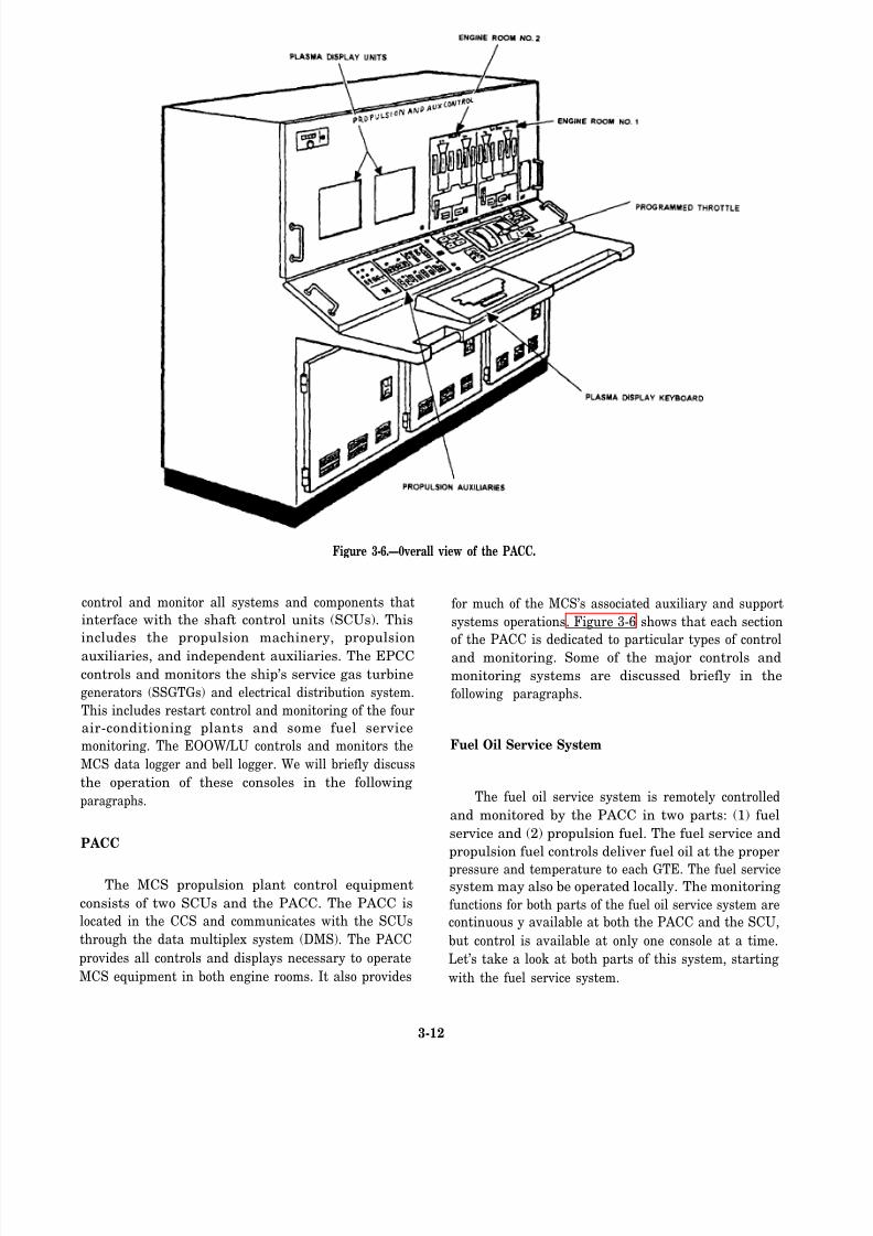
8/14/2019 US Navy Course NAVEDTRA 14115 - Gas Turbine Systems Technician Mechanical) 2
http://slidepdf.com/reader/full/us-navy-course-navedtra-14115-gas-turbine-systems-technician-mechanical 94/349
Figure 3-6.—0verall view of the PACC.
control and monitor all systems and components that
interface with the shaft control units (SCUs). This
includes the propulsion machinery, propulsion
auxiliaries, and independent auxiliaries. The EPCC
controls and monitors the ship’s service gas turbine
generators (SSGTGs) and electrical distribution system.
This includes restart control and monitoring of the four
air-conditioning plants and some fuel service
monitoring. The EOOW/LU controls and monitors the
MCS data logger and bell logger. We will briefly discuss
the operation of these consoles in the following
paragraphs.
PACC
The MCS propulsion plant control equipment
consists of two SCUs and the PACC. The PACC is
located in the CCS and communicates with the SCUs
through the data multiplex system (DMS). The PACC
provides all controls and displays necessary to operate
MCS equipment in both engine rooms. It also provides
for much of the MCS’s associated auxiliary and support
systems operations. Figure 3-6 shows that each section
of the PACC is dedicated to particular types of control
and monitoring. Some of the major controls and
monitoring systems are discussed briefly in the
following paragraphs.
Fuel Oil Service System
The fuel oil service system is remotely controlled
and monitored by the PACC in two parts: (1) fuel
service and (2) propulsion fuel. The fuel service and
propulsion fuel controls deliver fuel oil at the proper
pressure and temperature to each GTE. The fuel servicesystem may also be operated locally. The monitoring
functions for both parts of the fuel oil service system are
continuous y available at both the PACC and the SCU,
but control is available at only one console at a time.
Let’s take a look at both parts of this system, starting
with the fuel service system.
3-12

8/14/2019 US Navy Course NAVEDTRA 14115 - Gas Turbine Systems Technician Mechanical) 2
http://slidepdf.com/reader/full/us-navy-course-navedtra-14115-gas-turbine-systems-technician-mechanical 95/349
FUEL SERVICE SYSTEM.— The following six
monitoring and control functions of the fuel service
system are available at the PACC:
1.
2.
3.
4.
5.
6.
Fuel service tank level monitoring
Fuel service tank suction and return valves
control and monitoring
Fuel service pumps A and B control and
monitoring
Fuel service heater temperature monitoring
Prefilter differential pressure monitoring
Filter/separator differential pressure monitoring
PACC control of the fuel service system consists of
remote manual control of the suction and return valves
associated with the two service tanks. The PACC also
has automatic or remote manual control of the two fuel
service pumps.
The computer program for the fuel suction and
return valves allows the operator to open or close both
service tank valves simultaneously. Separate control
push buttons are available so the operator can operate
the pair of valves in one service tank independently of
the pair of valves in the other service tank. The computer
simultaneously sends the selected (open or close)
command to both of the valve motor controllers
associated with a single service tank. The PACC
controls all four valves through their respective SCU
computers.
The PACC operates the fuel service pumps
automatically when their respective motor controllers
are aligned for remote operation. The push-button
indicators at the PACC allow the operator to assume
manual control of the computer function program for the
fuel service pumps. The operator can depress the OFF,
LOW SPEED, or HIGH SPEED push button whenever
the service pump motor controller is in remote.
However, the computer program function will override
operator LOW SPEED and HIGH SPEED push-button
inputs if they are contrary to the automatic mode logic
of the computer program function. The operator may
command the operating fuel service pumps OFF at any
time. When a fuel service pump is in the OFF state, theautomatic mode of the computer program function is
inhibited for that pump. If the PACC is in the automatic
mode before a fuel service pump is started, the operation
of that pump is controlled by the computer function
program. The computer program controls the fuel
pumps with respect to fuel header pressure and time.
PROPULSION FUEL SYSTEM.— The following
four functions are available at the PACC for propulsion
fuel monitoring and control:
1. GTE fuel manifold pressure monitoring
2. GTE fuel valve controls and monitoring
3. GTE fuel purge control and monitoring
4. GTM fuel filter differential pressure monitoring
The propulsion fuel controls available at the PACCare limited to opening and closing the module fuel inlet
valve and fuel purging. Alarm and status indicators are
also located at the PACC.
The one solenoid-operated module fuel valve
external to the module is located in the fuel supply
piping near each GTE. This valve isolates the module
fuel system from the fuel service system. Push-button
indicators on the PACC allow the operator to control the
valve. From the PACC, the operator either can
electrically energize the valve closed or de-energize it
open. The operator has separate controls for each GTE.
By depressing the MODULE VALVE CLOSE pushbutton, the operator energizes the valve. This prevents
fuel flow to the GTE regardless of its operating status.
If the operator should depress the MODULE VALVE
CLOSE push button while a GTE is either ON LINE,
ON, or in a cool down, an automatic shutdown recurs.
At the PACC, the operator can initiate the fuel
purging function. The fuel purging function allows the
operator to drain the GTE manifold of any cold or
contaminated fuel before starting. Purge control is
available for each GTE through the PURGE ON and
PURGE OFF push-button indicators at the PACC. The
operator starts a fuel purge by depressing the PURGE
ON push button. This action energizes (opens) the
solenoid-operated purge valve in the GTE. The operator
depresses the PURGE OFF push button to de-energize
(close) the valve when fuel temperature and purity are
satisfactory. The position of the purge valve is indicated
by limit switches that control the PURGE ON and
PURGE OFF indicators at the PACC. A status message
is also shown on the plasma display unit (PDU). Now
let’s move onto the lube oil system.
Lube Oil System
Each MER contains an independent lube oil system
that is controlled and monitored from the PACC.
Monitoring is available continuously at both consoles,
but control is available at only one of the consoles at a
time. At the PACC, the operator can control the lube oil
service system pressure through the computer program
3-13
8/14/2019 US Navy Course NAVEDTRA 14115 - Gas Turbine Systems Technician Mechanical) 2
http://slidepdf.com/reader/full/us-navy-course-navedtra-14115-gas-turbine-systems-technician-mechanical 96/349
function of the lube oil service pumps. The operator
initiates these commands by depressing the push-button
indicators in the reduction gear lube section of the
propulsion mimic panel.
The motor-driven lube oil service pump control
signals from the PACC are sent via the DMS to the
appropriate SCU computer. Two modes of motor-driven
lube oil service pump control are available: MANUAL
and AUTO LEAD. The MANUAL mode allows the
operator to select pump speed with OFF, LOW SPEED,and HIGH SPEED push-button indicators. The AUTO
LEAD mode also allows the operator to select pump
speeds manually and tells the SCU computer which
pump to start first in response to the MRG hydraulically
most remote bearing pressure. The control location
switch on a lube oil service pump motor controller must
be in REMOTE before the computer can control pump
operation. Three push-button indicators at the PACC
allow the operator to assume control of the lube oil
pumps individually. Automatic and manual pump
operation are enabled when the operator depresses an
AUTO LEAD push button. AUTO LEAD prevents theoperator from commanding pump speeds that contradict
the lube oil service pumps automatic mode logic. When
pump control is in AUTO LEAD, the pumps cycle as a
function of the main reduction gear (MRG)
hydraulically most remote bearing pressure. Now that
we have described the lube oil system, let’s go on to the
air system.
Air System
There are two compressed air systems associatedwith the GTEs and the GTGSs: (1) the bleed air system
and (2) the high-pressure air system. Let’s look at the
bleed air system first.
The bleed air system contains the following four
distinct subsystems:
1. Starter air
2. Masker air
3. Prairie air
4. Anti-icing air
The bleed air system is supplied with combustion
air extracted from each operating GTE and SSGTG
compressor. Each GTE and SSGTG has a bleed air valve
that controls the flow of air from the engine to the bleed
air header. The bleed air valve for each GTE is
motor-operated and may be controlled from the SCU or
the PACC. The bleed air valve for the SSGTG is
solenoid-operated and may be controlled from the
SSGTG local operating panel (LOCOP) or the EPCC.
The starting air system is supplied by the
high-pressure air system through banks of high-pressure
air flasks and the bleed air header. The bleed air system
is the normal source of starting air when gas turbines are
operating. The high-pressure air system flasks are the
starting air source when no turbines are operating or a
bleed air PRESS LOW alarm is set.
At the PACC, the operator selects the starting air
source by depressing the starting air BLEED or HIGH
PRESS push-button indicator. These push buttons
interface with the starting air select computer program
function in the SCU computer. When the BLEED or
HIGH PRESS push button is depressed, a status
message appears on the PDU. The BLEED or HIGH
PRESS signal is sent with an ON or ON LINE command
to align the appropriate starting air valve. Valve
alignment for a BLEED or HIGH PRESS start is
initiated by the SCU engine state logic-on computer
program function. A GTE may be motored with bleed or high-pressure
air using the same air paths as a bleed or high-pressure
start. The only difference is the motor air regulator valve
is set to the motor position by the engine state
logic-motor computer program function. The motor air
regulator valve regulates air pressure to 22 psig when it
is in the motor position. At the PACC, the operator can
start the motor sequence for a GTM in the OFF state by
depressing the MOTOR push button.
The masker air system is aligned by the HULL
MASKER ON and OFF push-button indicators at thePACC. These push buttons operate the masker air select
computer program function in the SCU computer. The
HULL MASKER ON push button places the bleed air
transfer valve in the masker position if a GTE start or
motor command is not active in the same MER. The
HULL MASKER OFF push button places the bleed air
transfer valve in the start/motor position. The bleed air
transfer valve position is displayed on the PDU.
The prairie air system is supplied with bleed air
through a prairie air cooler and supply valve in each
MER. The PRAIRIE ON and OFF push-button
indicators provide manual inputs to the SCU computer
to issue commands to its connected prairie air supply
valve. When the prairie air supply valves are operated
from the PACC, the appropriate indicator illuminates
and a status message is displayed on the PDU.
The anti-icing system is supplied by bleed air
injected into the gas turbine intakes upstream of the
3-14

8/14/2019 US Navy Course NAVEDTRA 14115 - Gas Turbine Systems Technician Mechanical) 2
http://slidepdf.com/reader/full/us-navy-course-navedtra-14115-gas-turbine-systems-technician-mechanical 97/349
moisture separator/blow-in panels. A manually operated
anti-icing valve is located downstream of each GTM
bleed air regulating valve. The anti-icing valve position
is monitored by the computer in the SCU, which
generates a status message on the PDU. An ICING alarm
indicator for each GTE
propulsion mimic panel.
GTE Control System
is provided on the PACC
Control and monitoring of all four GTEs is available
from the PACC. However, normal control functions are
only available from either the PACC or the appropriate
SCU at any one time. The following items of the GTE
control system are discussed in this section:
1. Engine fan control
2. Engine state logic
3. Emergency controls
The engine fan control computer program functionis always enabled. It automatically operates the module
cooling fan and damper in response to three inputs: (1)
the GTE cooling air outlet temperature transducer, (2) a
GTE start command, or (3) the Halon release command.
The SCU computer controls the GTE cooling fan and
vent damper.
There are five possible engine states for a GTE.
Each engine state is associated with a computer program
function in the SCU computer. An engine state computer
program function senses the actual state of the GTE and
allows an operator to start an engine state change. The
push buttons that enable an engine state change are onthe gas turbine propulsion mimic of the PACC and SCU.
The five engine state logic computer program functions
are as follows:
1.
2.
3.
4.
5.
Off - Fuel off; power turbine (PT) brake on and
disconnected from programmed control
Motor - Engine off before alignment of an air
system for motoring
On - Engine running at idle, disconnected from
programmed control; PT brake on; and stop not
commanded
On line - Engine running, connected to
programmed control; PT brake off; and clutch
engaged
Cooldown - Engine running at idle, dis-
connected from programmed control; and PT
brake on
The SCU computer controls the GTE brakes, valve
alignment, cooling fan, and vent damper automatically
to fulfill any legal engine state change requested by the
operator.
The GTE emergency controls consist of three
separate, but interrelated, categories: (1) emergency
stops, (2) automatic shutdowns, and (3) GTE fire
detection and control.
An operator can initiate an emergency stop while a
GTE is in the ON or ON LINE state by depressing
EMER STOP, PRI OR RSV HALON RLSE, or
MODULE VALVE CLOSE. Depressing a HALON
RLSE or MODULE VALVE CLOSE push button
indirectly causes the SCU to send an emergency stop
command to the interim integrated electronic control
(IIEC). The SCU sends an emergency stop command to
the IIEC in response to a module Halon actuation alarm
or loss of GTE fuel manifold pressure.
An IIEC automatic shutdown is indicated when the
AUTO SHUT DOWN lamp on the PACC illuminates.
Each automatic shutdown causes the SCU computer tocarry out an emergency stop in addition to the IIEC
shutdown sequence. There are nine automatic
shutdowns associated with the MCS system. GTE lube
oil supply pressure low, power turbine vibration high,
and power turbine overspeed shutdown are examples of
automatic shutdowns. Five of the nine automatic
shutdowns are inhibited when BATTLE OVRD ON is
depressed. The five automatic shutdowns inhibited by
battle override are as follows:
1. GTM fail to light off or flameout shutdown
2. GTM lube oil supply low-pressure shutdown3. GTM power TIT high shutdown
4. GTM gas generator vibration high
5. GTM power turbine vibration high
The GTE tire detection system consists of three
ultraviolet flame detectors in the module and a signal
conditioner located under the module. When a fire is
detected, an alarm message appears on the PDU and a
MODULE FIRE lamp illuminates on the PACC and
SCU. At the PACC, the operator can activate Halon by
depressing the PRI OR RSV HALON RLSE push
button. AHALON SYSTEM ACTUATED alarm is then
displayed on the PDU.
Thrust Control System
The thrust control system consists of throttle/pitch
and brake mode control from an MCS control station.
3-15

8/14/2019 US Navy Course NAVEDTRA 14115 - Gas Turbine Systems Technician Mechanical) 2
http://slidepdf.com/reader/full/us-navy-course-navedtra-14115-gas-turbine-systems-technician-mechanical 98/349
This station can be the PACC, SCU, or the bridge control
unit (BCU). Throttle/pitch control is unified under the
programmed control and order difference computer
program functions when the NORMAL PRO-
GRAMMED MODE is selected. Throttle and pitch
controls are separated, and only available at the SCU,
when the LOCKOUT MANUAL MODE is selected.
Brake mode control is available in both modes.
However, brake engagement requires additional
operator action when LOCKOUT MANUAL isselected. The LOCKOUT MANUAL MODE places
unit control at the SCU and inhibits control station
transfers.
Programmed control is the normal method of
controlling a DDG-51 class ship’s speed. Programmed
control allows the operator to use a single lever to
position the controllable pitch propeller (CPP) blades
and GTE power lever angle (PLA) for a propulsion
shaft. TWO programmed control levers are available at
the PACC. The port and starboard programmed control
levers at the PACC maybe latched to ensure the shaft
horsepower is equal. The programmed control levershave a TRIM potentiometer for fine throttle/pitch
adjustments.
The programmed control computer program
function is designed for fuel economy. To provide this
fuel economy, the programmed control has been divided
into two operating regions: (1) the modulate
transmission mode used for slower ahead and astern
thrust settings, and (2) the modulate engine mode used
for faster ahead and astern settings.
Independent Auxiliaries Systems
The independent auxiliaries are systems controlled
and/or monitored through an SCU, which do not have a
direct impact on the propulsion and propulsion auxiliary
equipment. The seawater cooling system pumps are the
only independent auxiliaries controlled from the PACC.
The following independent auxiliaries are associated
with the MCS system:
1.
2.
3.
4.
5.
6.
7.
Seawater cooling system
Sewage and drainage system
Freshwater service system
Air-conditioning/chill-water system
High-pressure air system
Ship’s service air system
Internal communication system
Now that you have read about the controls available
at the PACC, let’s take a look at the ones available at the
EPCC.
EPCC
The EPCC provides centralized control of the ship’s
electric plant. The electric plant on the DDG-51 class
ships consists of the SSGTGs and the bus distribution
equipment. These features include a panel arrangement
of SSGTG controls and display devices in three groups,
one for each generator. Each group also has controls and
indicators for generator circuit breaker operation and
status. Load shedding, shore power switching, and a
visual synchronization presentation for all power
sources are added features. Limited status of each
air-conditioning plant status is displayed, and restart
controls for each plant are provided. The major electrical
generation and distribution equipment is located in
auxiliary machinery room (AMR) No. 1, MER No. 2,
and the generator room. Each of these spaces contains
one SSGTG and its associated switchboard.
An integral AN/UYK-44(V) computer provides for
control and monitoring of the electric plant. The MCS
requires that the electric plant remain operable if the
EPCC computer fails. So, many switch functions are
hardwired rather than using the DMS. The wiring is
from the EPCC to the controlled device in the generator
spaces. The required electric plant sensors are also
hardwired to the EPCC panel indicators to provide
status. An EPCC computer failure will cause a loss of
electrical plant alarm detection, EPCC and DMS
communications, and any displays at the PDU.The EPCC contains the controls and indicators that
the operator can use for remote operating and
monitoring of the ship’s service power generation and
distribution systems. Figure 3-7 shows the locations of
the control and indicator panels of the EPCC. We will
briefly discuss the following control systems that are
operated from the EPCC:
1.
2.
3.
4.
5.
6.
7.
8.
SSGTG control and monitoring
Electrical distribution monitoring and control
Circuit breaker operation
Gas turbine control
Generator control
Load shedding system operation
A/C plant operation
400-Hz power system operation
3-16

8/14/2019 US Navy Course NAVEDTRA 14115 - Gas Turbine Systems Technician Mechanical) 2
http://slidepdf.com/reader/full/us-navy-course-navedtra-14115-gas-turbine-systems-technician-mechanical 99/349
Figure 3-7.—EPCC panel locations.
Again, refer to the EOSS, EOP, and appropriate
technical manuals for a detailed description of the
operation of these systems.
SSGTG Control and Monitoring
Most SSGTG control systems reside in the LOCOPand exciter control panel (EXCOP). The EPCC and
switchboard control stations provide only discrete
inputs to the LOCOP and EXCOP. The LOCOP provides
monitoring for the gas turbine and generator, and control
for the gas turbine. This includes speed control, which
the LOCOP governor uses to regulate generator output
frequency. The EXCOP controls generator output
voltage by regulating generator field excitation. The
EXCOP is enabled by the LOCOP when gas turbine
speed exceeds 12,225 rpm.
A SSGTG has sensors to allow remote monitoring
of its gas turbine, generator, and supporting systems.The EPCC receives sensory information in any one of
the following four ways:
1. Directly from controllers or contact switches
2. Directly from temperature or level monitoring
devices
3. Discrete inputs from the SSGTG LOCOP
4. Analog inputs from the SSGTG LOCOP
Inputs to EPCC are processed by its computer to
determine if an alarm condition exists. Alarms are
indicated on the PDU and by an EPCC control panel
alarm indicator. At the EPCC, eight alarm conditions for
each SSGTG are displayed by specific alarm indicators. All other alarms are indicated by the appropriate
SSGTG summary alarm light above the PDU.
At the EPCC, there is one SSGTG summary alarm
LED for each SSGTG. The summary alarm light for
SSGTGS No. 1 and No. 2 operate when at least one of
22 alarm conditions occur. The summary alarm light for
SSGTG No. 3 operates when at least 1 of 25 alarm
conditions occur.
Any inputs to the EPCC that do not originate from
the SSGTG LOCOP are classified as direct. These direct
inputs can be either discrete or analog. Direct discrete
inputs are typically received from auxiliary contacts in
equipment controllers or contact switches associated
with a SSGTG support system. Direct analog inputs are
received from resistance temperature elements (RTE) or
tank level receivers associated with a SSGTG.
3-17

8/14/2019 US Navy Course NAVEDTRA 14115 - Gas Turbine Systems Technician Mechanical) 2
http://slidepdf.com/reader/full/us-navy-course-navedtra-14115-gas-turbine-systems-technician-mechanical 100/349
Electrical Distribution Monitoring and Control
An electrical switchboard has both analog and
discrete sensing devices for monitoring generator or bus
output and circuit breaker status. Alarm, status, and
control information flows between the switchboard and
the EPCC. The EPCC receives this information in one
of three ways:
1. Directly from potential transformers and current
transformers
2. Directly from circuit breakers
3. Discrete inputs from switchboard relay logic
circuits
The voltage and current signals from the current and
potential transformers are sent to transducers in the
EPCC to generate voltage, current, frequency, and
power signals. These signals directly drive the power
generation and distribution system output LED meters.
These signals are also sent to the computer for alarm
generation and the PDU’s demand display. The operator
can select the voltage displayed on the system output
panel meter by positioning the associated SOURCE
selector switch.
The electrical distribution system can be operated
manually from either the switchboard or the EPCC.
Automatic sequencing takes place in the switchboards
only when a fault condition exists. The EPCC does not
automatically control any circuit breakers as a part of
the standby generator start or any other function. The
switchboard relay logic and the LOCOP sequencer
generator breaker trip command are the only automatic
breaker controls.
Shore power breaker control from the EPCC islimited to the operator’s sending a trip command to each
breaker simultaneously by depressing the ALL CB
OPEN push button. All shore power close control and
phase monitoring devices are locally operated from
switchboard No. 2 in MER No. 2. When the shore power
breakers are closed, circuits in each switchboard will
automatically command each sSGTG governor to
DROOP to prepare for a shift from ship’s power to shore
power.
Circuit Breaker Operation and Control
The EPCC provides centralized control and
monitoring of 3 generator circuit breakers, 6 bus tie
breakers, and 12 shore power breakers. The push-button
indicators for
EPCC mimic
these circuit breakers are located on the
panel. Control of these circuit breakers
from the EPCC is enabled only when the operator
extinguishes the LOCAL CONTROL alarm light for a
switchboard.
EPCC operation of circuit breakers is accomplished
through the same circuits used by the switchboard
controls. Depressing an EPCC push-button indicator
allows the operator to energize a 28-volt dc close or trip
relay at the associated switchboard. The 10-position
synchronization CIRCUIT BREAKERS select switch
and SYNC MONITOR BYPASS push button enable
operation of the close circuit. When a relay is energized,
a control circuit in the breaker assembly energizes a
close or open trip coil to execute the desired status
change.
Gas Turbine Control
The gas turbine controls available at the EPCC
consist of gas turbine start air selection, governor
mode selection, and manual bleed air valve control.
Also available at EPCC are gas turbine start and stop
control and gas turbine frequency control. These
operator interfaces provide discrete inputs to the
LOCOP, which operates all SSGTG support systems
and gas turbine control elements.
The availability of an SSGTG start from the
EPCC is a function of the LOCOP 301 sequencer
ready to start discrete output, LOCOP LOCAL/
REMOTE switch, and switchboard voltage regulator
mode switch. When the LOCOP is in REMOTE, an
operator at either the switchboard or the EPCC can
start the SSGTG. When the switchboard GTG START
TRANSFER switch is in LOCAL, operators at both
the switchboard and the EPCC can start the SSGTG.
When the switchboard GTG START TRANSFER
switch is in REMOTE, an operator only at the EPCC
can start the SSGTG.
The manual SSGTG start controls at the EPCC are
the ON, HIGH PRESS, and BLEED push buttons. When
the operator depresses the ON pushbutton, the signal is
combined with the HIGH PRESS or BLEED indication
signal in the output multiplexer hardware. The start air
push buttons provide only a hardware logic signal within
the EPCC and do not cause the start air piping valves to
realign. Depending upon which start air indicator is
illuminated, the EPCC will send a high-pressure start orbleed air start signal to the LOCOP.
An SSGTG stop is always available from its
LOCOP, its associated switchboard, and the EPCC.
Depressing the EPCC OFF push-button switch sends a
signal to the LOCOP, which initiates a normal SSGTG
3-18
8/14/2019 US Navy Course NAVEDTRA 14115 - Gas Turbine Systems Technician Mechanical) 2
http://slidepdf.com/reader/full/us-navy-course-navedtra-14115-gas-turbine-systems-technician-mechanical 101/349
stop and opens the associated generator circuit breaker.
An SSGTG will also automatically stop if certain
abnormal conditions, such as slow start, module fire,
and so forth, occur.
The output frequency of each SSGTG is controlled
by an electronic governor in the LOCCP. The electronic
governor regulates the frequency by adjusting fuel flow
to the gas turbine. When the governor control is at the
EPCC, frequency adjustments can only be made from
the governor mode RAISE/LOWER switch at theEPCC. RAISE increases fuel flow to the gas turbine,
while LOWER reduces the fuel flow to the engine.
There are two modes of governor operation:
isochronous (ISO) and DROOP. The ISO mode is a
constant frequency mode where fuel flow is regulated
to maintain a constant generator output frequency. The
DROOP mode is a constant fuel flow mode where
increasing or decreasing the electrical load will cause
the frequency to decrease or increase, respectively. At
the EPCC, the operator selects the mode by depressing
either the ISPO or DROOP push button. When on shore
power, DROOP isswitchboard.
Generator Control
automatically selected by the
Generator field excitation is controlled by one of
two automatic voltage regulators in the EXCOP.
Generator output voltage can be controlled either
manually or automatically. One manual mode and two
automatic modes are available at both the switchboard
and the EPCC. In the MANUAL mode, excitation
current from the voltage regulator is set by a
motor-driven manual voltage adjust circuit in theEXCOP. The two automatic modes are differential
(DIFF) and DROOP. In these modes, the voltage
regulator sets the general output voltage to a level
determined by the setting of a motor-operated
potentiometer in the EXCOP. The DIFF mode is used
during parallel operations to allow the on-line SSGTGs
to share the reactive load equally at a selected output
voltage. The DROOP mode is used for operating
generators on an isolated bus. The DROOP mode is
basically the DIFF mode without cross-current
compensation.
Load Shedding System Operation
A load shedding operation can be started manually
or automatically. An operator can start manual load
shedding by depressing the appropriate INIT
push-button indicator at the EPCC or the spring-loaded
LOAD SHED switch at the switchboard. An operator
can start automatic load shedding by energizing either
an overpower relay in a switchboard or an overcurrent
relay on a shore power breaker.
When one overpower relay is energized, its contacts
operate tripping relays in each switchboard. The
tripping relays complete the power circuits to the trip
coils on selected circuit breakers. When a shore power
overcurrent relay is energized, load shed stage 1 and
stage 2 relays in switchboard No. 2 are also energized.This completes the power circuits in the switchboards
to trip the circuit breakers in the load shed system. All
circuit breakers opened during a load shed operation
must be closed locally. An exception is the
air-conditioning plant circuit breakers that can be closed
remotely from the EPCC. The tripped circuit breakers
cannot be closed until an existing overpower or
overcurrent condition is cleared.
Air-Conditioning Plant Operation
The normal and alternate supply circuit breakers forthe air-conditioning (A/C) plant can be closed from the
EPCC. At the EPCC, all four A/C plants have a remote
restart capability to bring a plant that was operating
before a power interruption back online. Each A/C plant
can be reconnected to the main bus and restarted from
the EPCC after a stage 2 load shed or an unexpected
power loss.
After a stage 2 load shed, all the primary and
alternate sources of power to each A/C plant will have
been tripped. Depressing the POWER RESTORE push
button at the EPCC closes the primary and alternate A/C
plant circuit breakers. All eight breakers will close,
regardless of the switchboard LOCAL CONTROL
alarm status, to energize each A/C plant controller.
400-Hz Power System Operation
The 400-Hz power systems consists of two
60/400-Hz static converters that feed separate 400-Hz
switchboards. On the DDG-51 class ship, the EPCC
cannot control or monitor any part of the 400-Hz power
system. Remote operation of the 400-Hz power system
is accomplished in combat systems maintenance central.The only 400-Hz monitoring done by the MCS is in the
interior communication switchboards.
Now that you have read about the monitoring and
control functions available at the PACC and EPCC, let’s
look at some of these controls available at the
EOOW/LU.
3-19

8/14/2019 US Navy Course NAVEDTRA 14115 - Gas Turbine Systems Technician Mechanical) 2
http://slidepdf.com/reader/full/us-navy-course-navedtra-14115-gas-turbine-systems-technician-mechanical 102/349
Figure 3-8.—Overall view of the EOOW/LU.
EOOW/LU
The EOOW/LU provides a central location for the
EOOW to monitor the status of the DDG-51 class
machinery plants. The EOOW/LU, shown in figure 3-8,
provides a centralized station for the basic functions of
accumulating, processing, and displaying the MCS
status. Additional functions of the console are to provide
the data for display on the console displays on the PDUs
on the bridge and in the combat information center
(CIC). This console also provides the means of loading
the bubble memories used by the other MCS consoles.
An operator can also use this console to change selected
alarm parameters in the software tables of the
AN/UYK-44 computer memories in the other consoles,
to set the date and time, and to update the shaft
revolutions count for use by other programs. The
following five principal operating units
with this console:
1.
2.
3.
4.
5.
are furnished
Two PDUs and one keyboard
A bubble memory tape drive unit
A bell log printer
An AN/USH-26(V) signal data recorder-
reproducer set
An AN/UYH-44(V) computer
In the following paragraphs, we will briefly
describe the units of this console. Again, for detailed
information, we recommend you consult the EOSS,
EOP, and appropriate technical manuals.
Plasma Display Units
The EOOW/LU panel has two PDUS with a single
keyboard. The panel CONTROLLED DISPLAY switchconnects the keyboard to either the left or right unit. The
keyboard CONTROLLABLE PLASMA/WORK-
STATION SELECT key swaps the PDU controllable
assignments for those of the workstation. This
arrangement separates the housekeeping and operation
functions. It also eases the PDU casualty operations for
the EOOW. The controlled PDU assignments include
the automatic alarm and status unit and the summary
group and demand display unit. The PDU workstation
capabilities include manual entry, log tape read, alarm
acknowledgement, bubble memory loadng, and edit
operations.
Manual entry is a keyboard message input system
that allows up to 32 characters. The message is released
to all PDUs in nearly simultaneous fashion. The log tape
reading function causes data from a tape cartridge to
appear on the PDU. This function is useful for reviewing
events that occurred previously. Single entry and tabular
3-20

8/14/2019 US Navy Course NAVEDTRA 14115 - Gas Turbine Systems Technician Mechanical) 2
http://slidepdf.com/reader/full/us-navy-course-navedtra-14115-gas-turbine-systems-technician-mechanical 103/349
modes are also available. The single entry mode displays
the latest entry and allows the operator to scroll to view
older data. The tabular mode displays up to 25 demand
display selections produced on six dates at a particular
time. The operator views an individual 25-entry set as a
log page and uses the keyboard to progress page to page.
The editing function allows the operator to adjust the
current date and time, alarm parameters, and shaft
revolution counter reset.
Bubble Memory Unit
When the EOOW/LU is first energized, the operator
must install bubble memory cassettes in the drive unit.
The computer’s start-up program will then cause the
console’s operating program software on the cassettes
to be loaded into the computer’s memory. Anytime the
computer is rebooted with the cassettes installed, the
operator must repeat the loading operation.
Each bubble memory for the MCS has unique
console software programming. When software
changes are required, a new AN/USH-26 master tape
cartridge is provided. The operator inserts the newcartridge in tape drive O. Bubble memory cassettes are
then loaded into the EOOW/LU bubble memory drive
unit. The EOOW/LU console transcribes the new master
tape program to the cassettes. New programs are set in
motion after the cassettes are installed in their MCS
console and the console’s initialization and bootstrap
procedure is run.
Bell Log Printer
The bell log printer is installed in the EOOW/LU
console front panel. It is a thermal style printer. The
printing head elements are heated and pressed againstthe heat-sensitive paper. The EOOW/LU computer
program issues the printer control and data print
commands.
Signal Data Recorder-Reproducer Set
The AN/USH-26(V) signal data recorder-
reproducer set is panel mounted. It is a cartridge tape
drive unit configured for four tape drives. The tape
drives are numbered drive 0 through 3. Only two tape
drives are used, however, and no hardware is installed
in drives 2 and 3. Drive 0 is a read only drive and drive1 is a write only drive. There is a magnetic tape driver
in the computer program. The driver interfaces with the
set to provide data writing and data program readings.
The driver also rewinds the tape and reads the set’s status
register.
A tape read or write operation starts when the
EOOW/LU computer sends a 16-bit command word to
the AN/USH-26(V). The tape unit performs the action
and follows up with feedback status. The feedback is a
status word reporting on the command word’s
operational success within the tape unit. Feedback status
after each command operation is issued. When the status
word is error free, the system is assured that satisfactory
command completion has resulted. If a status error
exists and may result in a local tape error alarm,
additional operations can be entered.
EOOW/LU Computer
Embedded in the EOOW/LU, the AN/UYK-44(V)
controls and monitors the MCS by using the DMS. The
AN/UYK-44(V) is a general-purpose self-contained
computer. The acronym AN/UYK-44(V) is defined as
follows:
AN – Army/Navy
U–
General utility
Y – Data processing
K – Computing
44 – 44th machine designated as AN/UYK
V – Various component groupings available
The computer has a set of hardware modules
contained in an air-cooled card cage. It also has a cooling
fan, a control and maintenance panel, and power
supplies. The basic modules are standard electronic
modules (SEMs), built to military standards
(MILSTDs). The control and maintenance panel is
located on each console for convenient start-up and
maintenance purposes.
The computer is the principle unit in the interchange
of information for the EOOW/LU. It works with the
DMS to accomplish these tasks. Each MCS console has
an AN/UYK-44(V) computer that may monitor the
propulsion plant, electric plant, auxiliary machinery,
and firemain and hazard detection systems. The control
and alarm input capabilities, however, will vary within
the program functions assigned to each consolecomputer. The computer enters a bootup process at
power turn-on. (It may also be rebooted from the control
panel whenever this is required.) During the boot
process, the operating program is loaded from the
bubble memory cassettes installed in a tape drive unit in
3-21

8/14/2019 US Navy Course NAVEDTRA 14115 - Gas Turbine Systems Technician Mechanical) 2
http://slidepdf.com/reader/full/us-navy-course-navedtra-14115-gas-turbine-systems-technician-mechanical 104/349
Figure 3-9.—Overall view of PCC.
the console. The program is unique to each console
housing a computer.
You have now read about CCS operations on the
DD-963, DDG-993, CG-47, and DDG-51 class ships.
Let’s now look at these operations for the FFG-7 class
ships.
FFG-7 CLASS CCS OPERATIONS
On the FFG-7 class ships, the CCS is the main
operating station. Most of the engineering plant
machinery can be controlled and monitored from this
station. The CCS is designed for remote monitoring andcontrol of the engineering plant with a minimum of
personnel. The major consoles of the engineering plant
on the FFG-7 class ships are the PCC, EPCC, and ACC.
The PCC provides all controls and displays needed to
operate the GTEs and their associated auxiliary and
support systems. The EPCC provides control of the
diesel generators and the electrical distribution
equipment. The ACC controls and monitors 15auxiliary subsystems. In the following paragraphs, we
will briefly discuss the operation of these consoles.
PCC
The PCC, located in the CCS, is the primary
propulsion plant operating station on the FFG-7 class
ships. The PCC provides all the controls and indications
required to startup and shutdown the propulsion system
and its related auxiliaries. It also provides the controls
and indications to operate the propulsion control system(PCS) in the programmed control mode or the remotemanual control mode. The PCC contains the signal
conditioning, logic, and multiplexing circuits, and the
processor for the PCS. Notice in figure 3-9 how each
section of the PCC is dedicated to particular types of
control and monitoring. In the following paragraphs, we
3-22

8/14/2019 US Navy Course NAVEDTRA 14115 - Gas Turbine Systems Technician Mechanical) 2
http://slidepdf.com/reader/full/us-navy-course-navedtra-14115-gas-turbine-systems-technician-mechanical 105/349
will briefly discuss some of the major control and
monitoring systems.
Fuel Oil service System
The fuel oil service system supplies fuel to the
GTEs. The control and monitoring functions available
at the PCC can be divided into two major categories: (1)
fuel oil service and (2) GTM fuel oil. Together they
function to deliver fuel oil at the proper pressure andtemperature to the individual propulsion GTEs.
The following eight fuel oil service monitoring and
control functions are available at the PCC:
1.
2.
3.
4.
5.
6.
7.
8.
Fuel oil service tank level monitoring
Fuel oil service tank suction and return valves
monitoring and control
Service pump suction valve monitoring
Service pump control and monitoring
Service pump discharge valve monitoring
Fuel oil heater discharge temperature
monitoring
Fuel oil prefilter strainer differential pressure
monitoring
Fuel oil filter/separator differential pressure
monitoring
The following three GTE fuel oil monitoring and
control functions are available at the PCC:
1. Emergency fuel supply valve monitoring
2. Supply cutoff valve control and monitoring
3. Fuel supply pressure monitoring
PCC control of the fuel oil service system consists
of remote control of the suction and return valves and
automatic or remote manual control of the fuel oil
service pumps.
The suction and return motor-operated valves are
electrically connected so when the tank suction valve is
opened, the return valve also opens. An OPEN/CLOSE
alternate-action push button controls the valves from the
PCC. The split-legend indicator provides the OPEN or
CLOSE status of the valves.
The fuel oil service pump operation can be
controlled at the PCC in either the auto speed advance
or the manual mode. The operator selects low speed,
high speed, or stop by depressing the corresponding
switch in the manual mode. The pump will advance from
low speed to high speed if the pressure is below 40 psig
and in the auto advance mode. The operator must
manually reset the pump to low speed.
The fuel pressure entering the GTE is monitored on
an edgewise meter located on the PCC. The supply
cutoff valve control at the PCC is provided by an
alternate-action switch. his switch is inoperative when
local lockout is in affect. The fuel oil supply cutoff valv
is a normally-closed, energized-open valve that fails t
the closed position upon loss of power. A split-legend
indicator on the PCC provides the status of the fue
supply cutoff valve.
The gas turbine emergency supply valve is a
normally-open, energized closed valve that fails to the
open position upon loss of electrical power. A
split-legend indicator at the PCC provides the status o
the emergency fuel supply valve.
Lube Oil System
The reduction gear lubricating oil service system
consists of two main parallel branches, each containin
a pump and a relief valve. An air motor drives a
coastdown pump that provides lube oil automatically
upon loss of electrical power to both lube oil pumps.
The right most panel on the PCC center section is
the auxiliary panel that provides the control and
monitoring for the MRG lube oil system. The norma
pump assignment signal to the indicator on the PCC
comes from the position of the local transfer switch a
the lube oil service pump control station. The manuamode requires the operator to start, stop, or change
speeds of the normal and standby pumps. The auto speed
advance mode increases the speed of the normal pump
starts the standby pump, and increases the speed of the
standby pump to maintain lube oil pressure. Lube oi
pressure is monitored at the most remote bearing for the
auto speed advance mode. The auto speed advance
mode has no control features, however, to reduce the
speed or stop either pump. Reducing the speed or
stopping either pump is a manual operation, regardles
of the position of the mode switch.
The PCC propulsion control panel provides a mimic
layout of the MRG with 29 indicators representing the
28 gearbox bearings and the one line shall bearing. Al
the bearing temperature alarms are set at 20 degree
above the maximum full power builder trial data
specified for each ship.
3-23
8/14/2019 US Navy Course NAVEDTRA 14115 - Gas Turbine Systems Technician Mechanical) 2
http://slidepdf.com/reader/full/us-navy-course-navedtra-14115-gas-turbine-systems-technician-mechanical 106/349
Air System
There are three main air systems associated with the
start air for the GTEs: (1) the bleed air system, (2) the
high-pressure air system, and (3) the emergency start air
system from the start air compressors (SACs). The
SACs are driven by the diesel generators.
The bleed air system provides air for starter air,
masker air, prairie air, and anti-icing air. The bleed air
system can be supplied by either of the running GTEs. An electric motor-operated bleed air valve is located in
each bleed air line inside the module enclosure. The
operator at the PCC can open and close this valve by
using the BLEED AIR VALVE OPEN/CLOSE
push-button indicating switch. The bleed air lines will
direct the bleed air to both the anti-icing system
associated with the respective GTE and the check valve
leading to the bleed air system header.
Each gas generator provides the bleed air for
anti-icing for its associated intake system and intake
plenum. At the PCC, the operator can use the controlalternate-action push-button switches and split-legend
indicators to control the solenoid-operated bleed air
shut-off valve and the motor-operated anti-icing valve.
The anti-icing system splits into two branch lines. One
line is for downstream of the moisture separators with a
manual valve that is normally open. The other line is for
anti-icing upstream of the moisture separators with an
isolation valve that is normally closed.
GTE Control System
At the PCC, the operator can use a three-position
switch to select the following three modes: (1) OFF
LINE, (2) MANUAL, and (3) AUTOMATIC. The
engine 1A and 1B start panels are mirror images of each
other. They provide the same controls and indicators
presented in the following four subsystems:
1. Pre-start status
2. Starting systems
3. Engine water-wash group
4. Sequencer mode switch
The off-line auxiliary mode is used for motoring and
maintenance. In the off-line mode, the fuel and ignition
cannot be enabled simultaneously. Tests of either the
ignition or fuel control system without starting the GTE
is accomplished in the off-line mode. An engine water
wash is also accomplished in this mode.
A manual mode of starting the GTE from the PCC
is available provided the 18 permissive conditions
required are satisfied. The READY TO START
indicator illuminates when all 18 pre-start permissive
conditions are met. The STARTER ON momentary-
action push button will begin the manual starting
sequence. The command to the start/stop sequencer
located in the FSEE enables the starter to turn the gas
turbine. The start/stop sequencer provides the time
sequence and engine parameters for information only,
The IGNITION ON and FUEL ON push-button
switches on the PCC must be manually operated to
provide the commands.
The automatic (program) mode starts the associated
GTE with automatic timed commands from the
start/stop sequencer in the FSEE. The same permissive
as in a manual start must be satisfied before the engine
can be started. The auto sequence START push button
initiates the auto start command to the start/stop
sequencer. The start/stop sequencer that initiates the
IGNITION ON and FUEL ON commands as acceptable
parameters are detected by the FSEE.
Three different methods for securing a GTE are
available at the PCC: (1) normal stop, (2) manual stop,
and (3) emergency stop. The engine will also be shut
down automatically either during a start sequence or
while running if certain faults are detected.
To initiate a normal stop, the operator can use either
the programmed control mode or the manual control
mode. The operator must use the manual stop, however,
if control was transferred from the local operating panel
(LOP) to the PCC after the engine was started. The
operator initiates a normal stop by depressing the
NORMAL STOP alternate-action push-button switch. A
normal stop can be aborted at any time before the
automatic fuel shutdown valve closes by advancing the
gas generator speed above idle.
The operator can initiate a manual stop in either the
programmed control mode or the remote manual control
mode. Before initiating a manual stop, the operator
should make sure the gas generator is run at idle speed
for 5 minutes. This precaution allows the engine parts
to cool evenly. A manual stop uses the circuitry in the
start/stop sequencer to stop the GTE. To provide the
manual stop command, the operator depresses the
MANUAL STOP push-button switch. This action
causes both automatic fuel shutdown valves to close.
The operator can initiate an emergency stop at any
time, in any control mode, and without regard as to
which console has GTE control. The EMERGENCY
3-24

8/14/2019 US Navy Course NAVEDTRA 14115 - Gas Turbine Systems Technician Mechanical) 2
http://slidepdf.com/reader/full/us-navy-course-navedtra-14115-gas-turbine-systems-technician-mechanical 107/349
Figure 3-10.-EPCC panel locations.
STOP OVERRIDE switch at the LOP must not be used
to accomplish an emergency stop at the PCC. The
emergency stop command causes the circuitry in the
LOP and FSEE to immediately de-energize the POWER
TURBINE OVERSPEED TRIP switch. This action will
cause both automatic fuel shutdown valves to close and
latch. This will shut down the GTE.
EOT Control System
The EOT control system on the FFG-7 class ships
is a standard Navy installation. The EOT provides an
electromechanical communication system between the
bridge and the PCC. The EOT on the PCC is located on
the lower or propulsion control panel and provides
continuous position indication. The EOT also provides
signals to the discrete multiplexer, which are inputs to
the PCS bell logger program.The EOT is used to relay standard orders from the
bridge to the PCC. When the bridge orders a change of
speed, one of the pointers in the EOT will point to the
requested speed. The PCC operator acknowledges the
order by moving the other pointer to match the bridge
pointer. This is done by using the knob below the EOT.
Throttle and Pitch Control System
The throttle and pitch control system provides
control of shaft speed and propeller pitch. The control
system can be operated in three modes: (1) local manual
control, (2) remote manual control, and (3) programmed
control.
The propulsion control system can be operated in
the manual control mode from the PCC or the LOP. The
programmed control mode is the primary mode of
operation and is initiated from the PCC or SCC. The
relationship between the pitch and throttle is
automatically scheduled by the PCS in the programmed
mode.
You have just read about the controls available at
the PCC. Now, let’s look at the controls available at the
EPCC.
EPCC
The EPCC contains the controls and indicators that
are used to remotely operate and monitor the ship’s
service power generation, distribution, and related
support systems. As shown in figure 3-10, each panel
incorporates a variety of control and monitoring
devices. These are alarm and status indicators, generator
status, mimic and distribution control, and plant system
3-25

8/14/2019 US Navy Course NAVEDTRA 14115 - Gas Turbine Systems Technician Mechanical) 2
http://slidepdf.com/reader/full/us-navy-course-navedtra-14115-gas-turbine-systems-technician-mechanical 108/349
control. In this section, we will briefly discuss the
following control systems that are operated from the
EPCC:
1.
2.
3.
4.
5.
6.
7.
8.
Diesel control and monitoring
Generator monitoring and control
Switchboard and distribution monitoring and
control
Shore power monitoring and control
Engine fuel service system
Auxiliary fuel service system
Jacket water system
Supervisory control system (SCS)
Again, refer to the EOSS, EOP, and appropriate
technical manuals for a detailed description of these
systems.
Diesel Control and Monitoring
Each ship’s service diesel generator (SSDG) has
sensors to provide remote monitoring of the diesel
engine and generator. The sensor information can be
viewed either on meters or the DDI. Sensor signals are
of two types: analog and discrete. Analog signals
represent parameters such as fuel levels, temperature,
pressure, or rpm. Discrete signals indicate the
occurrence of an event, such as a breaker open, breaker
closed, motor running, or motor not running.
Commands are control outputs from the EPCC, and
some action is expected in response to these signals.
The EPCC monitors several conditions of the SSDG
and displays them in several ways. The EPCC monitors
the diesel for the following conditions.
l
c
l
l
l
l
Engine fuel tank level, fuel pressure, and return
temperature
SSDG manifold pressure
Diesel fuel temperature
turbocharger air pressure
SSDG lube oil discharge pressure, temperature,
and sump level
Engine speed and exhaust temperature
Alarms on the EPCC are of two types: hardwired
and processor generated. Hardwired alarms come
directly to the alarm display unit; they sound an alarm
and light a lamp. The operator can cancel the sound by
depressing the ALARM ACKNOWLEDGE push
button. There are two levels of audible alarms at the
EPCC. The first level is a horn that signifies a problem
that requires immediate action to prevent damage or loss
of power. The second level is a bell for a problem that
needs correction as soon as practical.
The EPCC controls the diesel for start-up and
shutdown. The SSDG can be shut down either under
normal or emergency conditions. Under emergency
conditions, some diesel functions must be reset. Once
the generator set is running, the EPCC controls what
type of voltage regulation will be used and how the
governor will control SSDG speed and load. The
processor in the EPCC can control the operation of the
SSDG when the AUTO mode is selected.
The EPCC operator can start the generator set if the
LOCAL/REMOTE switch is ON and all safety
conditions are met. Starting from EPCC can be
automatic or manual. As engine speed builds up, a fuel
pressure switch opens and de-energizes a pilot cracking
relay. Once the engine is started and engine speed starts
to pick up, the governor will maintain SSDG speed.Initially the speed is controlled by the mechanical
governor until the limit setting is reached. Then, as
generator voltage builds up, the electrical governor
takes over control. Although 115-volt ac power is
required for this start sequence, the start can be
accomplished manually.
Under normal conditions, the operator can stop the
engine by pushing the engine STOP push button on the
local panel or depressing the remote PRIME MOVER
STOP push button on the EPCC. During this stop
sequence, the governor actuator is disconnected from
the governor control circuit. Dropping resistors apply afixed voltage into the governor actuator, causing it to go
to the shutdown mode. As the engine loses speed, the
fuel pressure drops and opens a switch that deactivates
the shutdown condition.
The operator can initiate an emergency stop at the
EPCC by depressing the EMERGENCY STOP push
button. This is the same sequence as the normal
shutdown, except the air intake system is closed off by
activating the engine air box relay. After an emergency
stop, the operator must manually reset the air intake
solenoid. Until it is reset, an engine-mounted shutdown
lockout switch will inhibit the engine from being started.
Generator Monitoring and Control
The generator section of each SSDG is monitored
for control and synchronizing. Transducers pick up
3-26
8/14/2019 US Navy Course NAVEDTRA 14115 - Gas Turbine Systems Technician Mechanical) 2
http://slidepdf.com/reader/full/us-navy-course-navedtra-14115-gas-turbine-systems-technician-mechanical 109/349
parameters that need to be monitored and send them up
to the EPCC. The parameters are processed by the DDI,
the SCS, and alarm circuits and gauges.
At the EPCC, the operator can obtain current,
voltage, frequency, and power readings by dialing in the
appropriate address on the DDI or by reading the
parameters directly off meters on the EPCC. Stator
temperature is monitored for each phase of the
generator. This is the only meter on the EPCC that reads
out in degrees centigrade rather than degrees Fahrenheit.The status of the voltage regulator and fields exciter is
indicated on the EPCC by two green lights, one for
manual mode and the other for automatic mode. Two
more green lights on the EPCC monitor the state of the
differential or droop selector.
The generator can be controlled through the
governor system, the voltage regulator, and the
synchronizer. The voltage regulator is used to vary the
field excitation that, in turn, controls the speed of the
generator.
The governor controls the generator set in two
different modes: isochronous and droop. The
isochronous mode is used to share the loading on
generators and to keep a constant speed or frequency.
The amount of fuel to the diesel determines the load each
generator can carry. In the droop mode, the frequency
will vary as the load is changed, but only within
predefine limits. This predefine area of droop is 0 to
6 percent of the bus frequency. The operator can control
the frequency of a generator manually from the front
panel of the EPCC. Using the increase/decrease knob
will change the frequency higher or lower, when the
operator needs to match a generator to a bus to parallelit.
The voltage regulator controls the generator output
through the field excitation. The voltage can be
controlled from the respective switchboards, except
switchboard No. 4. Switchboard No. 4 is in the same
space as the EPCC and has the MANUAL voltage
control on the EPCC panel. The manual preset
potentiometer on switchboard No. 4 at the EPCC gives
the field excitation circuit a reference from which to
work. The second mode is the AUTOMATIC mode. The
voltage regulator AUTO ADJUST potentiometer on the
EPCC can raise or lower the voltage by controlling a
motorized potentiometer on the generator set. The
motorized potentiometer sets a limit for field excitation
and voltage output. If the voltage goes up, feedback
causes the field excitation to drop, bringing the voltage
back into tolerance.
Switchboard and Distribution
Monitoring and Control
Power from the generator is monitored, controlled,
and distributed through a system of meters, electronics,
and circuit breakers. Under automatic operation, the
EPCC can perform all three functions through the
procesor software programs.
The circuit breaker status of each SSDG is
monitored for the generation, bus tie, and load shed
circuit breaker position. The EPCC will illuminate a
status indicator if the circuit breaker at the switchboard
is different from the switch position at the EPCC. Vital
power circuit breakers, such as fire pump controls, are
monitored at the EPCC on the vital power feeder circuit
breaker status panel.
The main breakers for the generator set, load
shedding, and bus ties are monitored on the EPCC.
Other circuit breakers can also be monitored, such as
those in the radar room or seawater pump. These circuit
breakers are monitored but not controlled from the
EPCC. Power supplies, including the uninterruptiblepower supplies (UPSs) and the console heaters, can also
be monitored. The total output for the ac generation
system is monitored for frequency, voltage, and current.
Individual bus ties can be monitored for current loads.
The operator uses the rotary switch on the EPCC to
select each bus tie.
The generator can be taken off the line if REMOTE
control is given to the EPCC and the generator switch is
turned to the TRIP position. The switch will work in the
CLOSE position only if the paralleling mode switch is
in the BYPASS or PERMISSIVE position and the
generator switch is at the BUS position. The
PERMISSIVE mode permits manual closure of the
breaker only when the automatic paralleling device
(APD) senses the generator is in synchronization with
the power bus. The BYPASS disables the APD so
synchronization has to be accomplished manually, The
generator breaker is closed manually by the operator.
The load shed circuit breaker can be opened and
tripped by the EPCC operator when the EPCC is in the
REMOTE mode. This circuit breaker can be either
manually or automatically tripped. When an overload
condition is sensed, the sensors from the generator buswill trip all the load shed circuit breakers. This action
will remove the nonvital bus from the bus ring.
The manual voltage control for the No. 4
switchboard is on the EPCC since the switchboard and
EPCC are both in the CCS. The No. 4 switchboard does
3-27
8/14/2019 US Navy Course NAVEDTRA 14115 - Gas Turbine Systems Technician Mechanical) 2
http://slidepdf.com/reader/full/us-navy-course-navedtra-14115-gas-turbine-systems-technician-mechanical 110/349
not have a remote control mode, therefore, there is no
LOCAL/REMOTE indicator on the EPCC for this
switchboard.
Shore Power Monitoring and Control
The EPCC can monitor the seven breakers
connected to shore power. At the EPCC, the operator can
trip all seven breakers by using the TRIP lever. Current
from the shore power source is monitored on a meter
that reads up to 3,000 amperes. Each of the seven
breakers can handle 400 amperes. The status of each
breaker is indicated at the EPCC by an illuminated blue
light indicator. The EPCC only controls the transfer of
shore power to ship’s power. The transfer of ship’s
power to shore power can only be accomplished by the
3SA switchboard.
Engine Fuel Service System
The EPCC provides for remote monitoring of the
SSDG’s fuel service system. Alarms at the EPCC
activate when the fuel tank level is beyond the high level
of 90 percent of tank capacity or lower than the low level
of 20 percent of capacity. Engine fuel discharge pressure
and manifold pressure are monitored by the EPCC
through the SCS. Engine fuel discharge pressure is
displayed on edgewise meters on the EPCC front panel.
To avoid transient alarms, the SCS provides a 16-second
delay on the level indicating alarms. We will take a
closer look at the SCS later in this chapter.
Auxiliary Fuel Service System
The EPCC controls the suction valves for each of
the six auxiliary fuel tanks. The EPCC operator can
control which tank is used to supply SSDG No. 4 or
SSDG No. 1 since they each have two tanks. The SSDGs
No. 2 and No. 3 share two day tanks; therefore, the
EPCC operator can only open or close the tanks. The
EPCC operator cannot transfer fuel to the day tanks.
This transfer must be done locally in auxiliary room
No. 2.
Jacket Water System
The jacket water system provides cooling water to
the jacket of the diesel engine and acts to cool the
lubricating oil. Each engine is served by its own jacket
water system. The water is circulated through each
system by a centrifugal pump that is a part of the diesel
engine.
Two resistance temperature detectors (RTDs) are
provided in the jacket water outlet line from the diesel
engine. One detector provides a signal to the EPCC to
provide continuous display and to actuate a HIGH
TEMPERATURE audible and visual alarm. The second
detector supplies a signal to an indicator mounted on the
diesel engine gauge board. A temperature switch is also
located in the diesel engine jacket water outlet piping.
The switch energizes a high temperature alarm on the
local switchboard.
A pressure transducer, located at the discharge of the
jacket water pump, provides a signal to the EPCC for
demand display readout. The expansion tanks have both
a liquid level gauge and a low level alarm. The low level
alarm energizes an audible and visual alarm at the EPCC
when the level drops to 7 1/2 gallons.
The EPCC controls the flow of seawater to the
jacket water system by opening or shutting the
motor-operated valve leading from the seawater chest.
A dual-illuminated indicator on the EPCC monitors the
OPEN or SHUT condition of the seawater valve. The
discharge of seawater, after it has picked up heat from
the jacket cooler, is routed to the overboard valve. The
EPCC has the control and monitoring functions
associated with this discharge.
Supervisory Control System
The program module for the SCS monitors the
electric plant for failures or degradation of performance.
The program either initiates corrective action or alerts
the operator to take corrective action. The supervisory
control is executed during the allotted 50-millisecond
interval of every 200-millisecond program cycle when
the supervisory control mode switch is in the AUTO
position. When executed, this function reads the
SHORE POWER indicator, the supervisory control
mode, and each SSDG control mode. If the electric plant
is on shore power, i f the supervisory control mode is off,
or if all SSDGs arc in the local control mode, control is
returned to the executive control program. Otherwise,
the status of each SSDG is established, and a bit pattern
is generated to identify the SSDG status and those
SSDGs operating in parallel. Each SSDG status is
recorded in a 16-bit computer word and updated eachprogram cycle. You should refer to the appropriate
technical manual for a detailed discussion on the SCS.
Now that you have read about the PCC and EPCC
controls for FFG-7 class ships, let’s take a look at the
controls at the ACC.
3-28

8/14/2019 US Navy Course NAVEDTRA 14115 - Gas Turbine Systems Technician Mechanical) 2
http://slidepdf.com/reader/full/us-navy-course-navedtra-14115-gas-turbine-systems-technician-mechanical 111/349
Figure 3-11.-Auxiliary control console.
ACC
The ACC, shown in figure 3-11, controls and
monitors 15 auxiliary subsystems and interfaces withthe software program of the EPCC. This interface
provides for demand display readout, alarmmonitoring, and the logging of data on the datalogger. Controls and indicators are arranged on the
ACC in a logical manner to help the operator relatethe panel control and monitoring functions to the
location of the auxiliary systems in the ship.
There are 15 specific auxiliary subsystemsinterfacing with the ACC. These 15 subsystems are asfollows:
1. Machinery space ventilation
2. Fuel fill, transfer, and purification
3. Chilled-water circulation
4. Waste heat water circulation
5. Compressed air plants
6. Main engine starting air
7. Potable water
8. Fill valves
9. Distilling plants
10. Saltwater service system
11. Drainage system
12. Masker, prairie, and bleed air
13. Sewage disposal system
14. Refrigeration system
15. IC/SM - Summary alarm
In this chapter, we will only mention thesesystems. For a detailed description of these systems
and the associated controls and indicators, refer to
GSE3/ GSM3, Volume 2, NAVEDTRA 10564.
The parameters that are considered critical arecontinuously displayed on the ACC for operator
monitoring. The parameters that are not consideredto be critical are available to the operator. For these
parameters, the operator uses the thumbwheel switchassembly to enter a specific code for the desired
parameter. This assembly is located next to thealphanumeric demand display. In addition to theauxiliary system parameters, all electrical system
and propulsion system demand display parameterscan be selected at the ACC.
The ACC interfaces with the data processor in theEPCC to exchange information. Three of the primary
functions performed by this interface are as follows:
1. Processing of the discrete and analog data to
provide a backup for alarm detection
2. Processing of data for output to the demanddisplay at the ACC
3. Data logging through communications withthe data processor in the PCC
Each of these functions is under the control of the
electric plant and auxiliary control system softwareprogram. This program is stored in the EPCC dataprocessor memory. Data is transferred from the
EPCC
3-29

8/14/2019 US Navy Course NAVEDTRA 14115 - Gas Turbine Systems Technician Mechanical) 2
http://slidepdf.com/reader/full/us-navy-course-navedtra-14115-gas-turbine-systems-technician-mechanical 112/349
to the ACC over digital data lines that connect the digital
transmitter circuits with the digital receiver circuits in
the ACC. This EPCC output data consists of address
information for both input and output data transfers and
digital data that drives the DDIs on the ACC.
We have now discussed the CCS operations for
DD-963, DDG-993, CG-47, and FFG-7 class ships. If
you have questions concerning the basic operation of
any of the consoles, we suggest you review the
appropriate sections. For detailed information on any of
these consoles, you should consult the appropriate
EOSS and technical manuals.
ENGINEERING CASUALTY CONTROL
The mission of engineering casualty control is to
maintain engineering services in a state of maximum
reliability under all conditions of operation. In the CCS,
casualty control includes both machinery and electrical
casualty control. Efficient CCS casualty control is the
result of effective personnel organization and training.
Remember, your ability to detect and identify signs of
initial trouble in your ship’s engineering equipment isbased on how well you have familiarized yourself with
engineering plant operations.
The details on specific casualties that can occur in
the CCS of a gas turbine-powered ship are beyond the
scope of this TRAMAN. For detailed information on
casualty control, you should refer to the engineering
operational casualty control (EOCC) portion of the
EOSS. The EOCC contains information you can use to
recognize casualty symptoms and identify their
probable causes and effects. The EOCC contains
information on the actions you can take to prevent a
casualty and the specific procedures your ship shoulduse to control single- and multiple-source casualties.
The EOCC manuals are available at each watch station
in the CCS for self-indoctrination. These manuals
contain official documentation to assist engineering
personnel in developing and maintaining maximum
proficiency in controlling casualties to the ship’s
propulsion plant.
In the CCS, the speed with which a corrective action
can be applied to an engineering casualty is frequently
of paramount importance. This is particularly true when
casualties might affect propulsion power, steering, or
electrical power generation and distribution. If
casualties associated with these functions are allowed to
increase, they may lead to serious damage to the
engineering plant. When possible risk of permanent
damage exists, the commanding officer has the
responsibility of deciding whether to continue operation
of the affected equipment under casualty conditions.
Although speed in controlling a casualty is essential,corrective actions should never be undertaken without
accurate information; otherwise, the casualty may be
mishandled, and irreparable damage and possible loss
of the ship may result. Speed in the handling of
casualties can be achieved only by a thorough
knowledge of the equipment and associated systems and
by thorough and repeated training in the routines your
ship requires to handle specific predictable casualties.
SUMMARY
This chapter has provided you with a variety of
information you can use to become an efficient gas
turbine specialist. In this chapter, we discussed various
engineering control system operations found on the
DD-963, DDG-993, CG-47, DDG-51, and FFG-7 class
gas turbine-powered ships. We described the methods
these systems use to exchange and process the
information necessary to control a gas turbine
engineering plant. This chapter also discussed some
basic operational procedures performed at the consoles
located in the CCS.
As you advance in the GS rating, yourresponsibilities for the engineering control system and
its operation will increase. The information provided in
this chapter should help you further understand the
electrical and electronic interfaces provided by the
engineering control systems. In this chapter, we also
referred you to other publications that will give you a
more in-depth explanation of the material we have
covered. You should study them to become a more
proficient and reliable technician.
3-30

8/14/2019 US Navy Course NAVEDTRA 14115 - Gas Turbine Systems Technician Mechanical) 2
http://slidepdf.com/reader/full/us-navy-course-navedtra-14115-gas-turbine-systems-technician-mechanical 113/349
CHAPTER 4
ENGINEERING SUPPORT AND AUXILIARYEQUIPMENT AND SYSTEMS
As a GS or even an engineer, you should know the
important role the engineering auxiliary equipment and
systems play in the overall operations of the ship. Eventhough most of the support and auxiliary equipment are
located in the engineering spaces, their systems extend
throughout the ship. For the most part, you and your
shipmates may forget what services this equipment and
these systems provide until your telephone rings and the
captain is on the line telling you he has soap in his eyes
and hair and no water to rinse with. As a GS, you are not
directly responsible for the making and distribution of
fresh water. You are, however, responsible for the
production of the steam or electricity that is needed to
operate the distilling plants.
This chapter will provide you with some basic
component descriptions for support and auxiliary
equipment and their systems. It also will discuss
operations, system interaction, and maintenance
requirements. Because of the similarities in the
equipment, system designs, and service requirements,
all the topics in this chapter will be discussed in general
terms.
OPERATION AND MAINTENANCE OF
SUPPORT AND AUXILIARY
EQUIPMENT
The proper operation of and good maintenance
practices for the support and auxiliary equipment should
be high on your list of priorities. Your attention to these
priorities should minimize the need for telephone calls
like the one we just described. In this section, we will
highlight some of the operational and maintenance
requirements that are crucial to the efficient
performance of the support and auxiliary equipment.
LOW-PRESSURE AIR COMPRESSORS
Basically, the reciprocating and helical screw are the
two types of low-pressure air compressors (LPACs)
used on gas turbine-powered ships. The helical-screw
type is the most widely used. It is rated at 100 cfm and
is installed on the CG-47, DDG-51, and FFG-7 class
ships. The reciprocating type is rated at 200 cfm and is
installed on DD-963 and DDG-993 class ships.
There are two LPACs installed on the DD-963,
DD-993, and FFG-7 class ships. Because of the ship
size, lower compressor capacity, and air volume
demand, there are three LPACs installed on the CG-47
and DDG-51 class ships.
Normal Operation
Gas turbine-powered ships will normally have at
least two LPACs aligned for operation to provide
low-pressure air for maintenance, service, control,
pneumatic power, and other utility purposes. For those
ships with only two compressors, the normal alignment
is to have one unit in constant run and the other in
standby. However, if one unit is out of commission, then
only one unit will be available.
For those ships with three compressors, normal
operations will have the cutout pressure switches set at
125 psig, 120 psig, and 115 psig. The compressor run
status will depend on the pressure cutout selection. For
example, the compressor set at 125 psig will be in
constant run. The unit set at 120 psig will be designated
as intermittent. The third unit, set at 115 psig, will be in
emergency standby.
Even though multiple units are installed on gas
turbine ships, they may not all be needed during routine
operations. During normal operations, one compressor
will usually provide sufficient air to supply the system.
Each LPAC has its own low-pressure air subsystem.
Each subsystem consists of the LPAC, a dehydrator, and
a main receiver. When in operation, each LPAC system
supplies air to a common vital air piping header. This
header usually runs longitudinally near the centerline of
the ship. The mission-essential equipment services are
isolated from the nonessential services by two priority valves, which actuate at 85 psig. These priority valves
do not operate very frequently–only when they are
needed. For example, if a large leak develops in the air
system, the priority valve will activate to maintain
sufficient operating air pressure to mission-essential
equipment. If the leak becomes too large for the priority
4-1
8/14/2019 US Navy Course NAVEDTRA 14115 - Gas Turbine Systems Technician Mechanical) 2
http://slidepdf.com/reader/full/us-navy-course-navedtra-14115-gas-turbine-systems-technician-mechanical 114/349
valve to handle, HP air can then be aligned through a
reducing station to supplement the LP air system.
Maintenance
Because of the wide range of use, proper
maintenance of the LPACs is extremely important. All
of the maintenance requirements are really very easy to
accomplish. Even though these requirements may seem
easy and almost insignificant, you should not
underestimate their importance. If these procedures are
not performed correctly and in a timely manner,
long-range detrimental effects on the equipment will
result. Always use the PMS when accomplishing
maintenance on LPACs. Remember, the PMS is only
sufficient to meet the minimum requirements. As a GS,
you must be aware of the more extensive requirements
that may be required by your type commander.
Troubleshooting
Generally, as the operator you will not be equipped
to correct all malfunctions; however, you should be able
to identify them when they occur and make a
preliminary diagnosis of the probable cause. There are
occasions when a malfunction can be caused by one or
more possible faults. Using fault logic diagrams and
flow charts, you should be able to investigate, isolate,
and correct a malfunction with a minimum amount of
compressor downtime. When you encounter troubles for
which the possible causes are not readily adaptable to a
fault logic diagram, you can usually find specific
explanations in the applicable manufacturer’s technical
manual.
In the following paragraphs, we will discuss some
common problems that may occur to both types of
LPACs and some key points to help you identify them
and minimize equipment downtime. If we state a
problem or possible cause that refers to a specific LPAC
type or model, we will indicate the type of model in
parentheses.
COMPRESSOR WILL NOT START IN
MANUAL MODE.– Check the following components
for the possible cause of this malfunction:
1.
2.
3.
4.
Power switch–Is it operational?
Fuses–Are they blown?
Last shutdown–Was the last shutdown an
automatic safety shutdown?
Control panel–Do the failure indicating lights
illuminate when start-up is initiated
5. Air receiver pressure–Is it below the falling
pressure set point, as it should be?
COMPRESSOR RUNS ONLY FOR A SHORT
PERIOD.– Examine the following conditions as the
possible cause:
1.
2.
3.
Compressor runs for 5 seconds or less–-Is the
water in the separator holding tank too low?
(Screw-type LPAC)
Compressor runs for only 5 to 12 seconds–
Check for the following conditions (screw-type
LPAC):
a. Oil pressure–Is it too low?
b. Injection water pressure–Is it too low?
c. Compressor–Is it running in the wrong
direction?
Compressor runs for only 12 to 15 seconds-Is
the oil pressure 100 low? (Reciprocating-type
LPAC)
COMPRESSOR DOES NOT AUTOMATI-
CALLY UNLOAD OR STOP.– Check the following
components for the possible cause:
1. Receiver air pressure switch-Is it operating?
it at the proper setting?
2. Compressor air intake butterfly valve–Is
closing properly? (Screw-type LPAC)
3. Ten-minute unloaded run timing relay–Is
operational? (Screw-type LPAC)
Is
it
it
4. Unloading solenoid valve–Is it operational?
(Reciprocating-type LPAC)
COMPRESSOR DOES NOT AUTOMATI-
CALLY START OR LOAD.– Check these
components:
1.
2.
3.
Receiver pressure switch–Is it operational? Is it
at the proper setting?
Compressor air intake butterfly valve–Is it
opening properly? (Screw-type LPAC)
Unloading solenoid valve–Is it operational?(Reciprocating-type LPAC)
AIR PRESSURE IS TOO HIGH AND
RECEIVER RELIEF VALVE IS OPENING.– Check
the following conditions:
1. Relief valve–Is it set incorrectly? Is it defective?
4-2

8/14/2019 US Navy Course NAVEDTRA 14115 - Gas Turbine Systems Technician Mechanical) 2
http://slidepdf.com/reader/full/us-navy-course-navedtra-14115-gas-turbine-systems-technician-mechanical 115/349
2. Valve alignment–Are the valves properly
aligned? Could the receiver discharge valve be
closed?
AIR PRESSURE IS TOO LOW.– Check for the
following conditions:
1.
2.
3.
4.
Excessive usage or system leaks–Are system
leaks causing excessive use of air?
Relief valves–Is there evidence of premature
opening or leak-by? Automatic blowdown valves–Is there evidence
of leak-by?
Injection water pressure–Is it low? (Screw-type
LPAC)
ABNORMAL NOISE.– Check for the following
conditions:
1.
2.
3.
4.
5.
Compressor air inlet–Is there insufficient air? Is
the filter blocked?
Compressor–Is it rotating properly?
Drive coupling–Is it defective? (Screw-type
LPAC)
Drive belts–Are the drive belts hose? Are they
defective? (Reciprocating-type LPAC)
Bearings–Are the bearings defective in either
the motor or compressor?
LOW OIL PRESSURE.– Check the following
components and conditions:
1. Oil pump suction piping–Are there loose
connections?
2. Oil pressure gauge–Is it faulty?
3. Oil level dipstick–Is the oil level below the low
mark on the dipstick?
4. Oil pump relief valve–Is this valve faulty?
5. Oil pump–Is it defective?
Even though the problems we listed are not
all-inclusive, they are probably the most reoccurring
problems you will face.
Overhaul and Repair
The overhaul and major repair of an LPAC is
usually performed by a ship’s repair facility. An
emergency situation, however, may require your
ship to perform major repair work on the
compressor. Normally, the compressor will be
replaced from a pool of reconditioned units. The
old units will be removed and replaced during a
ship repair availability (SRA) or overhaul. As a
GSM, you will be limited primarily to the
performance of general maintenance (PMS) and
minor repairs. In the following sections, we will
take a look at some of the components you will
need to maintain.
AUTOMATIC CONTROL VALVES AND
ASSOCIATED COMPONENTS
Even before the conception of the gas turbine-
powered ship, the Navy was using automatic
control valves and automated components. The
need to develop better and more reliable auto-
matic systems came into play with the
introduction of the unmanned engine room
concept to be implemented on gas turbine-
powered ships.
In every gas turbine-powered ship, automatic
control valves and their associated components
play a very important role in the operations of the
engineering plant. There is at least one automatic
control valve installed in every system in the
engineering plant. There arc so many different
types of automatic valves, however, we must limit
our discussion to some of the most prominent valve
types and their various applications, such as
controlling a tank liquid level, LO temperature, and
LO pressure. For the remainder of this section, we
will discuss some of the uses, operations, and
maintenance of these valves and their associated
components.
Normal Operation
In any system, the type of valve used is normally
determined by the needs of the system. We will talk
about some of the more commonly used valves and their
design and normal operating characteristics.
AUTOMATIC TEMPERATURE CONTROL
VALVES.– An automatic temperature control valve is
installed in the MRG LO system of a gas
turbine-powered ship to maintain the oil temperature
within safe operating limits. The type of valve used for
this purpose is of the same basic design for all classesof gas turbine-powered ships. The valve is
pneumatically operated via an externally mounted air
pilot controller. To function properly, the valve must first
receive the proper command air signal from the air pilot
controller. In fact, without the proper command air
signal from the controller, the valve is worthless.
4-3

8/14/2019 US Navy Course NAVEDTRA 14115 - Gas Turbine Systems Technician Mechanical) 2
http://slidepdf.com/reader/full/us-navy-course-navedtra-14115-gas-turbine-systems-technician-mechanical 116/349
Figure 4-1.-Bimetal l ic tem perature pi lot
control ler.
The externally mounted temperature pilot
controller shown in figure 4-1 is used in most gasturbine MRG LO systems. It receives inputs from the
increasing or decreasing length of the bimetallicsensing element, as shown in detail in figure 4-2, Thesensing bulb is installed in the MRG LO cooler outlet
piping where it senses the oil temperature before theoil enters the MRG. The tube, which is fixed at one
end, expands and contracts with temperaturechanges. Since there is a difference in the coefficientof expansion between the tube and the Invar rod,
temperature changes at the tube will createmovement of the rod. The movement of the rod is
transmitted and amplified by a lever that contacts thediaphragm assembly. As the rod moves, it regulatesthe amount of air pressure that is sent to or bled off
the automatic control valve. For example, if thecontroller shown in figure 4-2 should sense anincrease in liquid temperature, it will cause the tube
to lengthen, allowing a downward movement of therod, which, in turn, will increase airflow to the
automatic control valve. Consequently, a temperatureincrease will cause the automatic control valve toopen, thereby increasing the cooling medium or the
oil flow (depending on system design) through thecooler.
Figure 4-2.-Detail drawing of a bimetallic
tem perature pi lot c ont rol ler.
NOTE
Remember, our description of this operation
pertains only to the controller shown in figure 4-2.Normally, most automatic temperature control
valves used for cooling will fail to the ope
position. Our description and the controller shownin figure 4-2 are intended to provide you with abasic example of controller operation.
VALVE ACTUATORS.– As well as automati
control valves, there are several types of valve
actuators. Many actuators are pneumatic, such as theone in the automatic temperature control valve we
just described. Some valve actuators are mechanical A large number of valve actuators you will encounter
are electrical (solenoid type).
The mechanical actuators, either spring-loaded or
manual, are stand alone operators or are sometimesused
4 -4

8/14/2019 US Navy Course NAVEDTRA 14115 - Gas Turbine Systems Technician Mechanical) 2
http://slidepdf.com/reader/full/us-navy-course-navedtra-14115-gas-turbine-systems-technician-mechanical 117/349
to override a pneumatic or electrical type of actuatorin the case of an actuator or control valve failure. For
example, the steam diverting valve used on the CG-47 and DD-963 class ships has a valve handwheel.The handwheel is coupled directly through the
diaphragm to the valve stem to allow for manualoperation of the valve.
MECHANICAL LINKAGES.– The purpose of
valve operator mechanical linkages is to connect
remotely positioned valves with an operatorhandwheel by a series of rods (linkages) or a flexible
cable. Valve operator mechanical linkages are neededto control hard-to-inch valves, such as those locatedin the bilge area or the overhead. With proper
maintenance and upkeep, these mechanical operatorsserve as real time savers.
Now that we have discussed some of the automaticcontrol valves in terms of their basic operations and
components, let’s talk about how you will be requiredto test, inspect, and maintain them.
Tests and Inspec t ions
In this section, we will briefly discuss some of thetests and inspections you may be required to perform
on the various types of control valves and otherassociated components. Normally, you will conductperiodic tests and inspections when the component is
operating or according to approved maintenanceprocedures, such as the PMS.
LEVEL CONTROL VALVES– In testing and
inspecting level control valves, you will sometimes
require the assistance of a GSE. If the test orinspection pertains only to the valve itself or if thesensing features of the system are mechanical, such
as those on the WHBs, then you will be able tocomplete the checks on your own. If the operation of
the tank level sensing system you must test orinspect is electrical, however, then you will need theassistance of a GSE.
Frequently, you will inspect the operation of a
level control valve during normal operation. You willnormally perform tests on this valve during a
training evolution or a propulsion plant inspection, or
when you are planning to perform generalmaintenance. Regardless of the circumstances, you
must perform your inspections and tests of these valves according to the PMS or other authorized
procedures just as you would for any other test orinspection you are required to accomplish.
Basically, the two most popular types of levelcontrol valves you will need to be familiar with are
the solenoid-operated, needle type and thepneumatic-operated globe type.
Fi gure 4 -3. -Diaphragm con trol valve actu ator.
Solenoid Valves.– Solenoid valves are used
extensively throughout the engineering plant of any
gas turbine-powered ship. The solenoid valve we willdiscuss as our typical example is the one that is usedas a level control device in the FO service system on
DD-963 class ships. These valves do not have anyspecific tests or inspections as per PMS. According to
the NSTM, Chapter 505, “Piping Systems,” however,extensive damage may occur if these valves are notexercised periodically. This is particularly true if the
valves are located in areas that are difficult to keepclean, such as the bilges in main engine room (MER)
No. 1.
Solenoid valves should always be cycled before the
system is placed in operation. For proper operation,they should also be cycled at least once per month.
You can perform an operational test on a solenoid valve by using the thumbwheel override built into theside of the valve. When performing a test or
inspection, you should be checking for properoperation of the valve and leaks around the stem or
associated fittings and flanges.
Pilot Operated Valves.– Pilot operated valves
are normally tested and inspected according to thePMS. In performing a normal test, you will check thefull travel range of the valve stem and match it with
the scale mounted on the control valve actuator yoke,as shown in figure 4-3. To perform this test, you must
use an
4 -5

8/14/2019 US Navy Course NAVEDTRA 14115 - Gas Turbine Systems Technician Mechanical) 2
http://slidepdf.com/reader/full/us-navy-course-navedtra-14115-gas-turbine-systems-technician-mechanical 118/349
Fi gure 4-4.-External cont rol pi lot .
external air source with an in-line pressure regulatorthat is connected to the diaphragm inlet air
connection. With the air pressure regulator set atzero psi, the valve position indicator should be
pointing at zero percent on the position scale,indicating a normally closed valve. As you apply airpressure to the diaphragm, the valve should begin to
open. The amount of air pressure you apply to the valve will determine the percent of valve opening,
depending on the valve spring pressure. Normally, allof these valves will require approximately 5 psi of airpressure to start valve stem movement. At 20 to 22
psi, the valve should be fully open. If more airpressure than 22 psi is required to move the valve
stem, there is a good possibility the diaphragm has ahole in it, the stem seal is leaking, or the valve isbinding. Any one of these problems can seriously
affect the responsiveness of the valve, so you shouldinvestigate these conditions as soon as possible.
Generally, you will perform an inspection of a pilotoperated valve during normal valve operation.
During the inspection, you will need to check thepacking gland for leakage, watch the stem cycle for
smooth operation, examine the diaphragm telltale
hole and stem collar seal for air leakage, and check
the externally mounted pilot controllers, such as the
one shown in figure 4-4, for proper supply airpressure settings.
TEMPERATURE CONTROL VALVES.– The
types of temperature control valves we normally useare either the air pilot operated valves, such as theone we described earlier, or the spring-loaded,
bellows-actuated valves. These two valves are used inalmost every system in the engineering plant. You
will find either one located near every heat exchangerin the plant.
Pilot Operated Valves.– The tests and
inspections you will use for the pilot operated valvesare the same as those we previously described for the
level control valves.
Spring-Loaded Bellows Actuated Valves.– A
typical spring-loaded bellows actuated valve is shownin f igure 4-5. For this valve, you will normally
conduct
4 -6
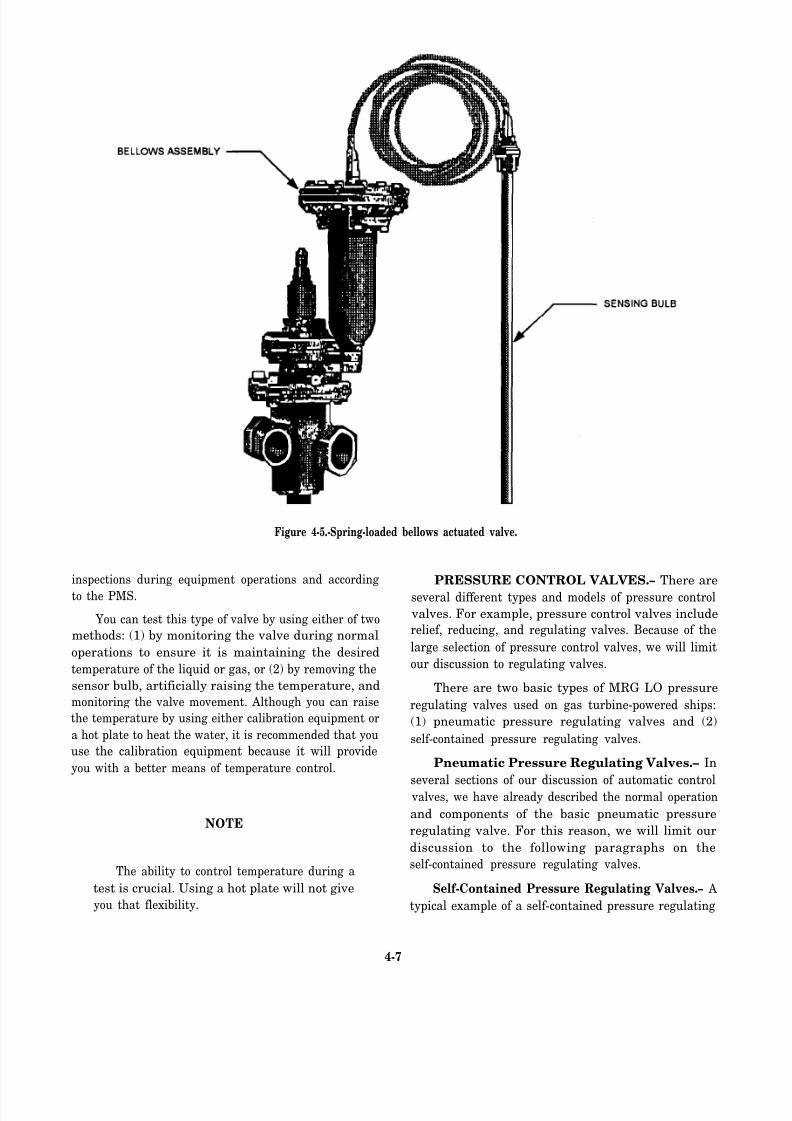
8/14/2019 US Navy Course NAVEDTRA 14115 - Gas Turbine Systems Technician Mechanical) 2
http://slidepdf.com/reader/full/us-navy-course-navedtra-14115-gas-turbine-systems-technician-mechanical 119/349
Figure 4-5.-Spring-loaded bellows actuated valve.
inspections during equipment operations and according
to the PMS.
You can test this type of valve by using either of two
methods: (1) by monitoring the valve during normal
operations to ensure it is maintaining the desired
temperature of the liquid or gas, or (2) by removing the
sensor bulb, artificially raising the temperature, and
monitoring the valve movement. Although you can raise
the temperature by using either calibration equipment or
a hot plate to heat the water, it is recommended that you
use the calibration equipment because it will provide
you with a better means of temperature control.
NOTE
The ability to control temperature during a
test is crucial. Using a hot plate will not give
you that flexibility.
PRESSURE CONTROL VALVES.– There are
several different types and models of pressure control
valves. For example, pressure control valves include
relief, reducing, and regulating valves. Because of the
large selection of pressure control valves, we will limit
our discussion to regulating valves.
There are two basic types of MRG LO pressure
regulating valves used on gas turbine-powered ships:
(1) pneumatic pressure regulating valves and (2)
self-contained pressure regulating valves.
Pneumatic Pressure Regulating Valves.– In
several sections of our discussion of automatic control valves, we have already described the normal operation
and components of the basic pneumatic pressure
regulating valve. For this reason, we will limit our
discussion to the following paragraphs on the
self-contained pressure regulating valves.
Self-Contained Pressure Regulating Valves.– A
typical example of a self-contained pressure regulating
4-7
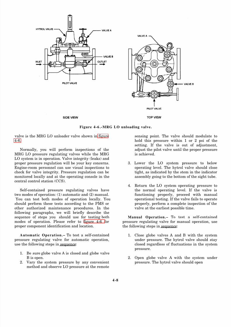
8/14/2019 US Navy Course NAVEDTRA 14115 - Gas Turbine Systems Technician Mechanical) 2
http://slidepdf.com/reader/full/us-navy-course-navedtra-14115-gas-turbine-systems-technician-mechanical 120/349
Figure 4-6 .-MRG LO unloading valve.
valve is the MRG LO unloader valve shown in figure4-6.
Normally, you will perform inspections of the
MRG LO pressure regulating valves while the MRGLO system is in operation. Valve integrity (leaks) and
proper pressure regulation will be your key concerns.Engine-room personnel can use visual inspections to
check for valve integrity. Pressure regulation can bemonitored locally and at the operating console in thecentral control station (CCS).
Self-contained pressure regulating valves havetwo modes of operation: (1) automatic and (2) manual.
You can test both modes of operation locally. Youshould perform these tests according to the PMS or
other authorized maintenance procedures. In thefollowing paragraphs, we will briefly describe thesequence of steps you should use for testing both
modes of operation. Please refer to f igure 4-6 f orproper component identification and location.
Automatic Operation.– To test a self-contained
pressure regulating valve for automatic operation,
use the following steps in sequence:
1. Be sure globe valve A is closed and globe valveB is open.
2. Vary the system pressure by any convenientmethod and observe LO pressure at the remote
sensing point. The valve should modulate tohold this pressure within 1 or 2 psi of the
setting. If the valve is out of adjustment,adjust the pilot valve until the proper pressure
is achieved. 3. Lower the LO system pressure to below
operating level. The hytrol valve should close
tight, as indicated by the stem in the indicatorassembly going to the bottom of the sight tube.
4. Return the LO system operating pressure to
the normal operating level. If the valve isfunctioning properly, proceed with manualoperational testing. If the valve fails to operate
properly, perform a complete inspection of the valve at the earliest possible time.
Manual Operation.– To test a self-contained
pressure regulating valve for manual operation, use
the following steps in sequence:
1. Close globe valves A and B with the system
under pressure. The hytrol valve should stayclosed regardless of fluctuations in the system
pressure. 2. Open globe valve A with the system under
pressure. The hytrol valve should open
4 -8

8/14/2019 US Navy Course NAVEDTRA 14115 - Gas Turbine Systems Technician Mechanical) 2
http://slidepdf.com/reader/full/us-navy-course-navedtra-14115-gas-turbine-systems-technician-mechanical 121/349
completely and stay in that position. This will be
indicated by the stem rising to the top of the sight
tube.
3. Close globe valve A. The indicator stem should
drop, indicating that the hytrol valve is closed.
(The speed of this closure is controlled by the
size of the orifice in the strainer and orifice
assembly. This small hole prevents excessively
fast closing.)
4. Open globe valve B. The unloading valve should
resume automatic operation.
VALVE OPERATOR MECHANICAL LINK-
AGES.– Valve operator mechanical linkages, as we
previously stated, are used to connect a remotely
positioned valve with an operator (handwheel). In this
section, we will discuss the tests and inspections for the
two types of mechanical linkages used on gas
turbine-powered ships: (1) the rods and universal joint
type and (2) the cable type.
Rod-Type Linkage.– In the design of the rod-typelinkage, a series of rods is connected together by
universal joints. The number of rods is determined by
the distance between the operator and the valve. The
number of joints is determined by the number of rods
used and the number of bends that are less than 90
degrees. If a bend of 90 degrees is needed, then a
gearbox assembly should be used.
Cable-Type Linkage.– In the design of the flexible
cable type of linkage, a wire woven cable is housed in a
flexible metal tube. In this type of linkage, gearbox
assemblies should also be used when 90-degree bendsare required.
The methods you will use for testing and inspecting
these two types of mechanical linkages are very similar.
These requirements are normally covered under the
PMS. When testing these operators, your primary
concern will be to check the freedom of movement. If
difficulty in operation occurs, there are several areas you
should inspect as possible causes of the problem. Use
the following sequence of steps:
1. Determine if the problem is the operator or the
valve. To do this, disconnect the operator fromthe valve and retest the operator. If it is still hard
to operate the operator, then the problem is the
operator.
2. Next, you must determine where the operator is
binding. The first and easiest method you can
use is to visually inspect the entire length of the
operator. The following are some key things to
look for:
a.
b.
c.
d.
e.
Positive signs of lubrication
Loose or improperly positioned hold down
brackets
Excessive bending in the cable or individual
universal joints
Improperly positioned packing gland or a
packing nut that is too tight on the deck or
bulkhead penetration fittings
Rusted or corroded fittings
In testing and inspecting automatic control valves,
mechanical linkages, and their components, you may
find that many of the problems will be obvious. In the
following paragraphs, we will discuss the more common
problems and tell you how to determine the required
repairs.
Maintenance and Repair Procedures
Most maintenance will be covered by the PMS or
maintenance procedures described in an appropriate
manufacturer’s technical manual. Therefore, we will
briefly discuss some preventative maintenance and
focus primarily on repair and component replacement.
Because they are the most important preventive
maintenance actions, we will start with cleaning and
lubrication procedures.
CLEANING AND LUBRICATION.– The
cleaning and lubrication of automatic control valves and
mechanical linkages is extremely important. You maynot realize how important it is until you are told to
operate a valve and you cannot get the valve to move
(open or close). Valves and operators located in high
moisture systems or in the bilge areas are extremely
susceptible to corrosion and will require more attention
than any other propulsion plant valves. A key thing to
remember is all valves do not use the same lubricants or
solvents.
High-pressure Air System Valves.– High-pressure
(HP) air system valves require a nonpetroleum-based
lubricant. This type of lubricant must be used because
of the static electric charge that is developed as the airmoves through the piping.
WARNING
Use of a petroleum-based lubricant can
create a very explosive condition.
4-9

8/14/2019 US Navy Course NAVEDTRA 14115 - Gas Turbine Systems Technician Mechanical) 2
http://slidepdf.com/reader/full/us-navy-course-navedtra-14115-gas-turbine-systems-technician-mechanical 122/349
CAUTION
Use of an inappropriate solvent can cause
damage to the components of the valve.
For these reasons, you should always follow an
approved materials listing on the PMS card or in the
manufacturer’s technical manual.
Automatic Control Valves.– The cleaning and
lubrication of automatic control valves and theiractuators is vital to the proper operation of every system
in the engineering plant. Electric solenoid valves and the
self-contained LO unloader valves we have already
described are the only automatic control valves that will
require cleaning but not lubrication. All the other types
will require continuous care involving both cleaning and
lubrication.
You must pay very close attention to the control
valve and actuator stem area. The stem and surrounding
area is where most of the dirt will collect. If the packing
gland has any leakage, corrosion will start in that area.
Valve Operator Mechanical Linkages.– Proper
cleaning and lubrication of valve operator mechanical
linkages is very important to maintain ease of operation.
These mechanisms are designed to be helpful and
timesaving because they allow you to operate valves that
are located in hard-to-reach places. Remember, if you
want to avoid waking three compartments over and five
decks down, you must properly maintain these
operators.
The rod or rigid type of operators with universal
joints and gear cases will require more attention than the
flexible cable operators. This is because the universal joints in the rod-type operators are not enclosed and are
constantly exposed to the environment. Being exposed,
these valves will require more frequent cleanings. After
cleaning, you must also apply a fresh coat of lubricant.
To maintain the gear cases, you should periodically open
them (if a cover is provided), remove the old grease,
clean them, and repack them with new grease.
The flexible cable valves are similar to a
speedometer cable in design, except each end of the
cable has a bearing installed. Each bearing housing is
fitted with a grease fitting, so you can use a grease gun
to provide lubrication.
OVERHAUL, REPAIR, AND REPLACEMENT
OF COMPONENTS.– Depending on the age of the
equipment and the availability of parts, it is usually more
cost effective to overhaul or repair the equipment rather
than replace it. Try to avoid complete replacement
whenever possible. In the following paragraphs, we will
discuss some tips concerning component repairs that
should save your ship money and your equipment
downtime.
Automatic Control Valves.– Automatic control
valves are very versatile and, if properly maintained,
they will provide long periods of service before
complete replacement is necessary. The air-operated
type of valve, however, will require more repair
attention than the other valve types.
Air-operated valves use a rubber diaphragm and
stem collar seal to operate. These rubber components
have a much higher failure rate than the valves that
operate without them. The main factor that causes
diaphragm failure is the system in which the valve is
installed. For example, the rubber diaphragm in a steam
system valve will have a much higher failure rate than
one on an LO system valve. Heat transfer from the
system piping through the valve body is one of the
primary factors that will contribute to the diaphragm’s
failure. Another factor is the amount of moisture and
foreign material (rust) in the air supplied by the ship’s
service air system. Over a period of time, any moisture
in the air system can cause the diaphragm to rot.
Moisture in the air system will also cause rust to form
in the piping. Eventually, the rust particles will flake off
and be carried downstream to the diaphragm area,
causing wear and holes in the rubber.
As maintenance goes, these rubber components are
inexpensive and easy to replace. When replacing the
stem collar seal, you must remember to treat it in the
same way as you would a bicycle tube. The seal is
delicate and can be easily damaged or punctured. Toavoid damage to the seal, you must clean the housing
thoroughly and make sure it is free of abrasives. You
must also be careful during assembly to avoid pinching
the seal between the metal surfaces.
Your ability to make shipboard repairs to the valve
body will also be a time-saver. You can perform minor
repairs, such as repacking and lapping the valve disk and
seat, with minimal effort. Occasionally, however,
according to the PMS or because of component failure,
you will have to remove the valve and have it delivered
to an IMA for an overhaul.
In the case of the air pilot controllers, all repairs will
have to be performed by an IMA. Sometimes the larger
IMAs will maintain a pool of controllers. If this is the
case, you need only to send a faulty air pilot controller
in and pickup an already reconditioned unit that is ready
for installation.
4-10

8/14/2019 US Navy Course NAVEDTRA 14115 - Gas Turbine Systems Technician Mechanical) 2
http://slidepdf.com/reader/full/us-navy-course-navedtra-14115-gas-turbine-systems-technician-mechanical 123/349
Electric solenoid valves will usually require
component replacement instead of repair. The whole
assembly is divided into two parts, the solenoid and the
valve. The diaphragm in the valve is the only minor part
in the whole assembly that can be replaced to effect a
minor repair. In most cases, you will have to replace
either the solenoid or the whole valve.
Valve Operator Mechanical Linkages.–
Mechanical linkages are designed to provide years of
trouble-free service when properly maintained.
Probably the leading cause of operator failure is
negligence. This statement pertains to both types of
operators we have discussed. For example, an operator
will work fine until it has to be detached from the valve
or component it is operating. Then, during reassembly,
a bracket bolt may be missing. Instead of finding a
replacement, you might think “Oh well, one bolt will
hold it.” The problem is there are usually two bolts per
bracket. Using one bolt will definitely cause a
misalignment in the operator. If both bolts are missing
and you are tempted to install bolts of the wrong size,
you will still cause the operator to be out of alignment.
Shipboard repairs to rigid rod-type operators will
normally consist of freeing up a binding universal joint
or gearbox, replacing the packing, and tightening or
replacing any loose or missing support bracket bolts.
Binding universal joints are usually caused by excessive
bends or operator misalignment, as we have already
discussed. Depending on the operator’s age, however,
the joint may be worn out and you will need to replace
it. In most cases, the joint will be attached to the operator
rod end by a removable pin. If necessary, you can drive
out the pin with a punch. You can then remove the joint
and install a new one.
Gearbox repairs will be more difficult and in some
cases impossible to perform. Many of the gearboxes are
sealed units and repairs cannot be made. Even if the
gearboxes can be opened, you must call on your
machinery repairman to manufacture the new gears. If
the materials and equipment are available, you might be
successful. In most cases, however, it is easier to order
a new part.
Even though the flexible valve operators have fewer
parts than the rigid operators, shipboard repairs to
flexible valve operators are usually limited by the
availability of parts. This means most repairs must beaccomplished by outside activities. Depending on the
problem, sometimes the repair personnel can make the
repairs while leaving the operator in place. If this is not
possible, the whole operator should be removed and sent
to an outside repair facility.
OPERATION AND MAINTENANCE OF
SUPPORT AND AUXILIARY SYSTEMS
Up to now, we have talked about some of the
components associated with the support and auxiliary
systems. You should realize, however, that these
components are just a small portion of the total design
and operation of these systems. In this section, we will
tell you how these components interact to make the
support and auxiliary systems work. Although we will
briefly describe how the systems operate, we will focus
primarily on their maintenance and repair.
SHIP’S SERVICE AIR SYSTEMS
The ship’s service air system (SSAS) on a gas
turbine-powered ship is used extensively everyday. It
supplies air for maintenance, service, control,
pneumatic power, and other utilities. All of these
services come under one or more of the four subsystems
we will describe in the following paragraphs.
Electronics Dry Air System
The electronics dry air system is a vital system in
which the air is dried twice. Before entering the system,
the air passes through a condenser filter and then a type
11 dehydrator. The electronics dry air system services all
electronic systems, AC plants, and gun and missile
control panels that require dry air.
Ship’s Vital Air System
The ship’s vital air system produces air that is dried
only once. The only difference between the vital and
nonvital air systems is the equipment serviced. Theship’s vital header services the sonar dome, ammo
elevator, close-in weapon system (CIWS), No. 3 GTG
signal air, and many others.
MER Vital Air System
Like the ship’s vital air system, the MER vital air
system is tapped off the main header just before the
priority valve. This tap location ensures that all vital
equipment will have air if there is high air use or a leak
occurs in the nonvital subsystem. This air is for vital
propulsion equipment. It is also the receiving piping foremergent y air from the HP/LP air reducing station. On
the CG-47, DD-963, DDG-993 class ships, there is one
HP/LP air reducing station located in MER No. 1. On
the DDG-51 class ships, there are two HP/LP air
reducing stations, one in each MER.
4-11

8/14/2019 US Navy Course NAVEDTRA 14115 - Gas Turbine Systems Technician Mechanical) 2
http://slidepdf.com/reader/full/us-navy-course-navedtra-14115-gas-turbine-systems-technician-mechanical 124/349
Ship’s and MER Nonvital Air Systems
These two subsystems, the ship’s nonvital air
system and the MER nonvital air system, are used for
all of the same types of service. Both systems are
designed to service all nonvital equipment, such as the
pilothouse window washer, tool outlets, and several
other nonvital equipment units.
The number of compressors needed to support these
four basic subsystems will vary according to the class
of ship. It does not matter, however, how many
compressors are available because all these subsystems
can be cross-connected or isolated from each other with
the proper valve confikguration. An occasion may arise
when none of the LPACs may be available. If this
occurs, then the SSAS can be cross-connected with the
HP air system (HPAS). For this configuration, you must
make sure all nonvital systems are isolated. Isolating the
nonvital system will help you make certain the depletion
of the HPAS is minimal.
Tests and Inspections
Tests and inspections for the SSAS are normally
scheduled according to the PMS, with the primary
emphasis on the individual components, such as the
compressors, driers, dehydrators, and reducing valves.
For the driers and dehydrators, you can accomplish
many of the required tests and inspections during normal
operation. Technically, you are performing an
inspection of each unit every time you take hourly
equipment readings.
For the system piping, you can accomplish a
complete inspection for leaks and any other problemduring the normal watch routine and while you are
performing valve maintenance. While you are
inspecting the air system, some of your major concernsshould be damaged or rusted piping, broken or missing
pipe hangers, and even painted or missing rubber
isolation mounts.
Troubleshooting
In troubleshooting the SSAS, using common sense
is your best tool. For example, visualize a situation in
which you discover a large leak in the air system.
Because the leak is very large, you must use the priority
valve to isolate air to the nonvital header. The air
pressure, however, still does not completely restore.
Where should you look first for the cause of this
problem?
Your first step is to narrow down the possible
sources of the problem by isolating each of the three
remaining SSAS subsystems, one at a time. The first
subsystem you should check is the MER vital air,
Identify the operating equipment supplied by the MER
vital air subsystem. If practical, secure these equipment
units. Once you have isolated the MER header and air
pressure is restored, then you have narrowed down thelocation of the leak to this area. If air pressure does not
restore, however, then you will need help from outside
the MER. Before proceeding, you must check with allother divisions who receive service from the MER vital
air system and have them inspect their equipment and
piping until the problem is isolated.
Maintenance
Upkeep of the overall SSAS will consist of two
main areas: (1) valve maintenance and preservation and
(2) maintenance of the compressors and their associated
driers and dehydrators. Valve maintenance will include
maintaining and preserving the reducing stationassemblies and all the manual valves. Maintenance of
the manual valves will normally be limited to general
cleaning and lubrication. Shipboard maintenance for the
reducing stations will include adjusting, lubricating, and
cleaning the air inlet strainers.
Like tests and inspections for the air driers and
dehydrators, the maintenance of valves should be
carried out according to the PMS.
BLEED AIR SYSTEMS
As you work toward becoming a GSM2, you will
need to be familiar with the major equipment, basic
operations, and general maintenance of the ship’s bleed
air system. You can find a detailed discussion of this
system in Gas T urbine S ystem s T echnician (Electrical)
3/ Gas Tu rbine Systems T echn ician (Mechanical) 3,
Volume 2, NAVEDTRA 10564,
In this section, we will give you only a brief
overview of the following five major bleed air systems:
l
l
*
l
l
Bleed air collection and distribution system
Masker air system
Prairie air system
Start air system
Anti-icing air system
4-12

8/14/2019 US Navy Course NAVEDTRA 14115 - Gas Turbine Systems Technician Mechanical) 2
http://slidepdf.com/reader/full/us-navy-course-navedtra-14115-gas-turbine-systems-technician-mechanical 125/349
For each of these systems, we will describe the major
equipment, maintenance, and system similarities or
differences among the ship classes.
Bleed Air Collection and Distribution System
The bleed air collection and distribution system
collects compressed air extracted from the compressors
of all propulsion turbines and SSGTGs. It then
distributes the air to the four other systems as needed.This is the primary system and contains the bulk of the
hardware, consisting of regulating valves, isolation
valves, collection piping, the main header, distribution
piping, and relief valves.
The bleed air collection and distribution system
extracts compressed air from the customer bleed piping
of the turbines through a bleed air shutoff valve. To
prepare the air for use throughout the system, a
regulating valve reduces and regulates the extracted air
to 75 psi. Once regulated to 75 psi, the air enters the main
bleed air header and is distributed to the start air, maskerair, prairie air, or anti-icing air system, depending on the
valve configurations of these individual systems.
TESTS AND INSPECTIONS.– Your respon-
sibilities for testing the components of the bleed air
collection and distribution system will be minimal. For
example, if you are stationed on a twin-shaft ship, there
are only 13 valves outside of the main engine enclosures
that will require some kind of testing. These valves
include the three 14-stage bleed air valves, seven bleed
air regulating valves (three GTG valves and four GTM
valves), the bleed air isolation valve, and two relief valves. If you arc stationed aboard an FFG-7 class ship,
only two valves will require testing, one relief valve and
the pressure regulator and flow control valve. For the
most part, all testing for these valves will be covered
under the PMS or as part of the Engineering Operational
Procedures (EOP). According to the PMS, you will test
the operation of the 14-stage bleed air valves and the
relief valves. The PMS for the 14-stage bleed air valve
must be conducted quite frequently and usually in
conjunction with a major propulsion plant inspection
(safety checks). According to the PMS, the relief valves
must be periodically tested for proper lifting and
reseating pressure.
Other tests and inspections will be more frequent.
For example, you must test the bleed air isolation valves
whenever the No. 3 SSGTG is started. You must test the
other isolation valve (header) daily according to the EOP
to ensure proper operation.
As for inspections, the bleed air regulating valves
and the overall system must be inspected and monitored
continuously by engineering personnel while it is in
operation.
TROUBLESHOOTING.– Troubleshooting a
problem in the bleed air collection and distribution
system is usually fairly easy to accomplish. Remember,
the movement of air follows the same principles as
electricity: Air always takes the path of least resistance.
In the following paragraphs, we will describe a few of the more common problems and some of the steps you
can take to isolate their probable causes.
Bleed Air System Pressure is Too High.– When the
bleed air system pressure is too high, use the following
steps, in sequence, to isolate the problem:
1. Check and compare pressure readings
throughout the plant to verify gauge accuracy.
2. Check the bleed air regulating valves. For CG-,
DD-, and DDG-class ships, if more than one
GTG is operating, you will need to alternate the
securing of the bleed air regulating valves to
pinpoint which one is faulty. Also, because
bleed air from the main engines is not used very
often, the regulating valves tend to
overpressurize the system. For FFG-class ships,
check the bleed air regulating and flow control
valve. If a start air compressor (SAC) is
operating, you should check the start air
system’s isolation check valve for leak-by into
the main bleed air header.
Relief Valve is Lifting.– When this condition
occurs, check the following two areas:
1. System pressure is too high–Follow the
guidelines in the preceeding paragraph for high
system pressure.
2. System pressure is normal–Is the relief valve
faulty? Is it improperly set?
System Pressure is Too Low.– If the system
pressure is too low, take the following steps:
1. Verify the accuracy of the gauge.
2. Check the relief valves for blowby.3. Check the system for leaks.
4. Check the pressure regulating valve for proper
operation.
MAINTENANCE.– You must perform the
maintenance of all valves (electric or air operated) in the
bleed air collection and distribution system according to
4-13
8/14/2019 US Navy Course NAVEDTRA 14115 - Gas Turbine Systems Technician Mechanical) 2
http://slidepdf.com/reader/full/us-navy-course-navedtra-14115-gas-turbine-systems-technician-mechanical 126/349
the PMS. Except for the module bleed air cutout valves,
you may in some cases use a type of planned
maintenance program. You will also maintain the valves
in the remaining subsystems of the bleed air system
according to the PMS and possibly a planned
maintenance program. The planned maintenance
programs are usually contractual agreements between
the Navy and the manufacturers of the valves. In some
cases, valve manufacturers may keep a rotational pool
of valves that will allow the ship to remove and replace
all of the system valves with new or rebuilt ones during
an SRA. Plans, such as these, will significantly reduce
system downtime and increase reliability for months.
Because all the bleed air system valves are basically
maintained in the same manner, this is the last time we
will discuss their maintenance requirements.
Masker and Prairie Air Systems
Both the masker and prairie air systems take the hot
bleed air from the bleed air collection and distribution
system. These two systems cool the air in independentcoolers before sending it to the masker emitter belts or
leading edge of the propeller blades. The purpose of
masker air is to muffle or modify the ship’s machinery
noises that are transmitted into the water through the
ship’s hull. Prairie air is then used to disguise the
propeller noise signature. We will discuss the basic
design and operational characteristics and maintenance
requirements of both systems in the following
paragraphs.
MASKER AIR SYSTEM.– The number of valves
used and the direction of airflow through the masker air
system will depend on the ship’s class. Because of thedifferences in masker air system designs, we will
discuss the system installed on the CG-47, DD-963, and
DDG-993 class ships. After we discuss this system, we
will then point out the differences in the systems
installed on other gas turbine-powered ships.
CC-47, DD-963, and DDG-993 Class Ships.– For
the masker air system in these ships, the air is first
extracted from the bleed air header and then piped to the
masker air valve (masker cooler valve). The masker air
valve is located between the header and the masker air
cooler. When the operator selects the ON position forthis valve, the hot bleed air flows through the cooler to
an air/water cyclone-type separator and then to the
masker transfer valve. The masker transfer valve is a
two-way directional flow valve. The valve position
selected by the operator will determine the direction of
airflow, either to the start air system or to the masker air
system. As the air is directed to the masker air system,
the bleed air pressure is then reduced by a pressure
regulating valve before the air is sent to the masker air
distribution manifold. The air then enters the
distribution manifold where it can be directed manually
to any of the desired emitter belts.
DDG-51 Class Ships.– The basic masker air system
installed on the DDG-51 class ships is the same as the
one installed on the CG-47, DD-963, and DDG-993
class ships. The only difference worth mentioning is the
way in which the masker air (cooler) valve operates. Thetype of masker air valve installed on the DDG-51 class
ships is manually operated. The type installed on the
CG-47, DD-963, and DDG-993 class ships is an electric
solenoid-controlled valve that is operated from the
PACC or the PLCC.
FFG-7 Class ships.– The masker air system
installed on the FFG-7 class ships has only two
characteristics in common with the masker air systems
installed on the other ship classes: (1) where the masker
air comes from and (2) the basic principles of operation.
In the FFG-7 class ships, the air is piped from thebleed air cooler through a normally open, manually
operated cutout valve and then to the masker air pressure
regulating valve. The air pressure is reduced and the air
is then piped to the two masker air supply cutout valves.
These two solenoid-controlled valves are then operated
from the auxiliary control console (ACC) in the CCS to
send air to one or both emitter belts.
PRAIRIE AIR SYSTEM.– Now let’s discuss the
prairie air system. The prairie air systems installed on
all gas turbine-powered ships have the same basic
design. They all have a solenoid-controlled valve that isoperated from the control consoles, a cooler, and the
associated piping that supplies air to the rotary air seal
on the OD box for distribution to the propeller blades.
Because these valves are operator selected either open
or closed, the airflow and pressure are not reduced or
regulated by these valves before the air is required for
use.
TESTS AND INSPECTIONS.– For both the
masker and prairie air systems, all tests and inspections
must be carried out according to the PMS.
There are two primary tests that are normallyconducted on these systems. In the first test, you will use
a portable air flowmeter to check for the proper airflow.
For the other test, you will check the operational
effectiveness of these two systems against an acoustical
range. In most cases, you can perform the two tests at
the same time unless all flow rates arc set correctly
before you make the required passes over the range.
4-14

8/14/2019 US Navy Course NAVEDTRA 14115 - Gas Turbine Systems Technician Mechanical) 2
http://slidepdf.com/reader/full/us-navy-course-navedtra-14115-gas-turbine-systems-technician-mechanical 127/349
TROUBLESHOOTING.– Neither the masker or
prairie air system will have a vast number of
components to cause the system to fail. This means
troubleshooting a problem with either system should be
fairly simple. Let’s take a look at some problems that
may occur and their possible solutions.
Incorrect Masker Air System Pressure.– In the
masker air system, when the air pressure is either too
high or too low, use the following steps:
1. Check the pressure gauge for accuracy.
2. Check the bleed air header pressure.
3. Check the regulating valve for the proper setting.
Incorrect Prairie Air System Pressure.– If the air
pressure in the prairie air system is too high or too low,
take the following steps:
1. Check the pressure gauge for accuracy.
2. Check the bleed air header pressure.
If there is no air pressure in the prairie air system,
take the following steps:
1. Check the pressure gauge for accuracy.
2. Check the system supply cutout valve to make
sure it is open. Sometimes this valve will
indicate OPEN and will actually be closed if the
pin connecting the actuator to the valve should
shear. A sheared pin will allow the actuator to
move, but not the valve.
Incorrect Masker or Prairie System Airflow.–
Incorrect airflow in either system can be caused by the
following conditions:
1. Improper system pressure–Is the regulating
valve faulty or improperly set?
2. Misaligned manual belt cutout valves
3. Blocked holes in the masker belts or propeller
High Masker or Prairie System Air Tempera-
ture.– If the air temperature is too high in either the
masker or prairie air system, take the following steps:
1. Check the gauge for accuracy.
2. Check the masker or prairie air coolers.
a. Is the seawater cooling system pressure
insufficient?
b. Are the cooler tubes clogged?
Any of these conditions could be the cause of high air
temperatures in either system.
Start Air Systems
The start air systems installed on all gas
turbine-powered ships serve the same purpose: To start
all the ship’s propulsion or electric plant turbines. Even
though the start air systems have the same goal, the start
air system in each ship class will accomplish this goal
in its own individualized way. Except for the DDG-993
class ships, all gas turbine-powered ships have two
methods of starting each propulsion or electric plant
turbine: (1) LP start air and (2) HP start air. In the
DDG-993 class ships, the start air system has only LP
start air capabilities for the propulsion turbines.
Because there are several differences in the start air
systems installed in the different ship classes, we will
first discuss the basic system installed on the CG-47,
DD-963, and DDG-993 class ships. We will then discuss
the differences.
CG-47, DD-963, AND DDG-993 CLASS
SHIPS.– The start air systems installed on the CG-47,
DD-963, and DDG-993 class ships use hot bleed airfrom the bleed air header and cool masker air from the
masker air system to provide each turbine with LP
starting air. These start air systems were designed to use
a bleed-air/masker-air combination because the
propulsion turbine and GTG starters consume a lower
amount of air when the air temperature is increased.
There are three modes of operation for the starter air
system: (1) normal, (2) motor, and (3) emergency. With
the bleed air system in the automatic mode, the normal
position for starter air is the primary method of operation
for GTM starting and the motor position is the primary
method of operation for GTM motoring. Also, with the
bleed air system in the automatic mode, the ECSS logics
for the start air system valves will automatically align
for either starting or motoring the GTM. When a GTG
is started, however, its start air system does not interface
with the ECSS logics. This is why a manual air valve
alignment must be used for GTG starting.
GTM Starting and Motoring.– In the start air
system for a GTM start, there are five valves that must
be aligned before the GTM start air valve can open:
1.
2.
3.
4.
5.
MASKER XFRMASKER CLR
HI TEMP BLEED
MOTOR AIR REG
MIXING BYPASS
4-15

8/14/2019 US Navy Course NAVEDTRA 14115 - Gas Turbine Systems Technician Mechanical) 2
http://slidepdf.com/reader/full/us-navy-course-navedtra-14115-gas-turbine-systems-technician-mechanical 128/349
Fi gure 4-7 .-DD-963 start air syst em (sim plified).
If you trace the system shown in figure 4-7 and
compare it with the following listing of the five valvesand their positions, you will see the proper valvealignment for GTM LP starting and motoring.
VALVE VALVE POS ITION FOR:
TYPE STARTING MOTORING
MASKER XFR START START
MASKER CLR OPEN OPEN
HI TEMP BLEED OPEN CLOSE
MOTOR AIR REG OFF ON
MIXING BYPASS CLOSE OPEN
Now that you have seen the valve alignment for
GTM LP starting and motoring, let’s discuss the valve alignment for GTG starting.
GTG Starting.– If you reexamine figure 4-7, you
can see that the valve alignment for a GTG start or
motor should be same as for a GTM motor. The onlyexception is that it does not matter what position themotor air regulating valve is in.
HP and LP Starting.– As we mentioned at the
beginning of this section, there are two methods of
starting—using either HP or LP air. Again, if youstudy f igure 4-7, you can see that the HP air system
interfaces with the start air system just before themotor air regulating valve. Notice also in figure 4-7that the HP-to-LP air reducing valve pressure and
the orifice are configurations that only apply to DD-963 ships.
The CG-47 ships share this basic system design,but the CG-47 HP/LP reducing station has a lower
outlet pressure (45 psig), which eliminates the needfor the orifice pack. Because of the location at which
the HP air enters the system, there is only one valvethat must be aligned, the motor air regulator.
4-16

8/14/2019 US Navy Course NAVEDTRA 14115 - Gas Turbine Systems Technician Mechanical) 2
http://slidepdf.com/reader/full/us-navy-course-navedtra-14115-gas-turbine-systems-technician-mechanical 129/349
Figure 4 -8.-DDG-51 start air sys tem (sim plified).
As we indicated earlier, the start air systems we have just discussed are found on the CG-47, DD-963, andair DDG-993 class ships. In the following paragraphs,
will point out the differences found on the tworemaining systems installed on the DDG-51 and
FFG-7 class ships.
DDG-51 CLASS SHIPS.– The start air system on
the DDG-51 class ships shares some basic similaritieswith the systems we have already described. If youstudy figure 4-8 and compare it to figure 4-7, you can
see the start air system for the DDG-51 class shipsperforms the same functions as the DD-963 system
with fewer valves. Instead of using five valves, the
DDG-51 start air system does the same job with onlytwo valves. The console controls are also muchsimpler in design. At the DDG-51 console, you will
have only one of two choices to make–to use HP air orbleed air to start the engine.
In the DDG-51 start air system, another design
difference is that the HP-to-LP air reducing stationoutlet that is 75 psig. In the DDG-51 system, anorifice pack is not installed because additional air
pressure reduction is simply not necessary.
4-17

8/14/2019 US Navy Course NAVEDTRA 14115 - Gas Turbine Systems Technician Mechanical) 2
http://slidepdf.com/reader/full/us-navy-course-navedtra-14115-gas-turbine-systems-technician-mechanical 130/349
Figure 4-9 .-FFG-7 start air system (simplified).
FFG-7 CLASS SHIPS.– The last start air system
we will discuss is the one installed on the FFG-7
ships. This system is shown in figure 4-9.
If you look closely at figure 4-9, you should notice
there are three methods or sources of air for startingthe GTMs: (1) HP air, (2) LP (bleed) air from the start
air compressors, or (3) LP (bleed) air from the cross-bleed piping from the online GTM. You can use any of the three methods, depending on the circumstances.
In most cases, HP air will be available and will be the
primary means of starting the GTMs during acasualty. As you can see in figure 4-8, the air
pressure is reduced to a workable pressure by theHP/LP air reducing valve, which alleviates the needfor further pressure reduction. This design is very
similar to the one used on the CG-47 class ships.
The second method is using LP (bleed) air fromthe start air compressors. In this method, two startair
4-18

8/14/2019 US Navy Course NAVEDTRA 14115 - Gas Turbine Systems Technician Mechanical) 2
http://slidepdf.com/reader/full/us-navy-course-navedtra-14115-gas-turbine-systems-technician-mechanical 131/349
compressors (SACs) provide LP air for GTM starting.
The two SACS are attached to the front end of the
SSDG. One is installed in the No. 2 SSDG enclosure.
The other one is installed in the No. 4 SSDG
enclosure. In this system, the air is treated in much the
same way as it is in the DD-963 system. Hot
compressed air is supplied by one of the SACs. The
air is then split into two flow paths before reaching
the starter. Part of the air will remain hot; the other
part will be routed through a cooler. The hot air will
then be mixed with the air that was routed through thecooler. The mixing of air takes place in the
temperature regulating valve (similar to the DD-963
mixing valve), which will regulate the start air
temperature to 400°F.
The third method, referred to as cross-bleed
starting, is not very frequently used. In fact, you will
use it only when performing the PMS or during a
casualty. Remember, this method can only be used if
the other GTM is already running with a gas generator
(GG) speed of 7,500 rpm or greater. The reason the
GG speed has a specific set point is because at a lower
GG speed, sufficient air volume cannot be supplied to
the GTM for starting.
TESTS AND INSPECTIONS– You must carry
out all tests and inspections for all the start air systems
according to the PMS. Generally, there are two tests you
will conduct on these systems. The first test is checking
for the proper operation of the HP/LP start air reducing
stations installed on the CG-, DD-, and DDG-51 class
ships. Because the reducing stations are not used very
frequently, they must be tested periodically.
Another periodic inspection you must make is
on the SACs installed on the FFG-7 class ships.
Even though the SACs on the FFG-7 class ships are
used and tested more frequently than the reducing
stations installed on the CG-, DD-, and DDG-51
class ships, you must still inspect them
periodically. As a GSM, you should keep in mind
that the air produced by these compressors may be
used to start your turbines, but the maintenance and
upkeep of these compressors may not be your
responsibility. As a watch stander, however, you
will be responsible for reporting any discrepancies
you might observe during the operation of these
units.
TROUBLESHOOTING.– At times, your proce-
dures for troubleshooting a start air system can be quite
difficult. If all the problems that might arise were
mechanical, then solving those problems would not
be that difficult. Unfortunately, a start air system is
highly reliant on electronic interfacing with the
control consoles. With so many different variables
associated with the control consoles and the start air
system, such as FO, LO, air permissive, and so forth,
in most cases you will need to call upon a GSE to assist
you in troubleshooting this system. Occasionally,
however, you may get lucky and encounter a problem
that is strictly mechanical. With this in mind, we
will discuss some of the mechanical and minorelectrical problems you might encounter in ‘the start
air system and some methods you can use to
identify the faulty components.
Air Valve Will Not Cycle.– If the air valve will not
cycle, perform the following checks:
1. Check the valve’s actuating air supply. On the
DD-963 and DDG-993 class ships, the actuating air is
supplied from the bleed air system. In all the other
ship classes, the activating air is supplied from the
ship’s LP air system. If activating air is available,
check the pilot air inlet fitting and its filter to see if
they are clogged.
2. Check the pilot actuator assembly. Most of
the valves for this assembly are equipped with a
manual override device. First, activate the
override. If the valve operates, you have narrowed
the problem down to a faulty solenoid, a faulty or
loose cannon plug, or loss of the command signal.
If the valve still does not operate, it may be jammed
or the actuating piston seal may be leaking by and
the resulting pressure may be insufficient to over-
come the spring pressure.
3. Check the cannon plug connection. If the
connection is clean, dry, and tight, then have a GSE
check the solenoid and the control circuit.
Faulty Air Valve Appears to Operate
Properly.– This situation will occur occasionally when
the pin that connects the pilot actuator with the valve
stem shears. When this occurs, the actuator will move
properly but the valve stem will not. For a good
example of this situation, visualize attempting a start
on a DD-963 class ship. During the start attempt,monitor the start air manifold pressure. It will likely
read normal. Notice, however, that once the GTM
start valve opens, the air pressure drops to zero. When
this occurs, you will need to either replace the valve
or, if time permits, disassemble the valve and install
a new pin.
4-19
8/14/2019 US Navy Course NAVEDTRA 14115 - Gas Turbine Systems Technician Mechanical) 2
http://slidepdf.com/reader/full/us-navy-course-navedtra-14115-gas-turbine-systems-technician-mechanical 132/349
Air Valve Opens and Closes Slowly.– As a GSM,
you must watch for the valve’s performance. The valve
may open and close, but it will take an abnormally long
time to do so. When this occurs, you should immediately
check the system’s filters and low-point drains for
excessive amounts of water and debris.
Anti-Icing Air System
The last bleed air subsystem we will discuss is the
anti-icing system. Even though this system is not used very often, it is still an important part of the overall bleed
air system.
The function of the anti-icing air system is to use
hot bleed air to prevent the formation of ice on the
gas turbine cooling air inlet moisture separators on
the FFG-class ships and the combustion air intakes
on all the ship classes. Among the different classes
of gas turbine ships, the ice detectors will be
installed in critical locations to warn the operators
when an icing condition exists. If an icing condition
should occur, the operators in the CCS will always
inform the engine-room personnel and direct them
to open the anti-icing valves manually. These valves
will control the pressure and flow of air that will be
required to raise the intake air temperature to a level
that will eliminate the icing condition. Except for the
FFG-7 class ships, all classes of the gas turbine-
powered ships are equipped with this anti-icing
valve system. Although the anti-icing air system on
the FFG-class ships is equipped with a manual
cutout valve, the pressure is automatically regulated.
TESTS AND INSPECTIONS.– On all classes of
gas turbine-powered ships, tests and inspections of the
anti-icing air system will not be performed very often.
The tests will mainly pertain to the operational
capability of the system’s valves. You will perform these
tests according to the PMS. Your main concerns will be
to test these valves for freedom of movement and check
the console indicator lights for proper valve position
indications.
The inspections you will perform on the
components of the anti-icing air system are very
important. You must use great care whenever you
conduct these inspections and handle thesecomponents. You must be so careful because the
primary component for this system is located inside
the turbine’s combustion air intake. You must regard
any work inside the combustion air intake with the
same care and concern you would any work on the
main reduction gear. To protect the safety of
personnel and equipment, you must adhere strictly
to all security and safety guidelines. While
inspecting the bleed air manifold, your primary
concern will be not so much the manifold itself
but its fasteners. In inspecting the fasteners, you
must make certain that all the bolts are made of
the proper material (stainless steel) and that they
are properly tightened and safety wired. You must
check every bolt for tightness, corrosion, and the
presence of properly installed safety wire.
TROUBLESHOOTING.– As a GSM, you should
have very little difficulty troubleshooting a problem
in this system. Because the majority of the system’s
valves are manually operated, most of the system’s
problems will be related to improper alignment. The
only exception to this is the anti-icing air system
installed on the FFG-class ships, which has a pressure
regulating valve installed. If you should identify this
valve as the source of a problem, you should approach
its repairs and testing the same way as you would any
of the other bleed air system automatic control valves
we have discussed. The most important thing to
remember about the pressure regulating valve in the
FFG anti-icing air system is that it is not used very
often and may have a tendency to stick.
MAINTENANCE.– In all gas turbine-powered
ships, your maintenance of the anti-icing air system will
be fairly limited to valve maintenance and the required
repairs you will determine after performing the
previously mentioned tests and inspections.
WASTE HEAT RECOVERY SYSTEMS
As a GSM, there is a good chance you will
encounter one or both types of waste heat recovery
systems we will discuss in this section. The first type of
waste heat recovery system we will discuss is installed
on the CG-47, DD-963, and DDG-993 class ships. The
other system we will describe is installed on the FFG-7
class ships.
In this section, we will briefly discuss the role of the
waste heat recovery system during routine operations.
We will focus on some of the maintenance and upkeep
requirements for this system.
CG-47, DD-963, and
DDG-993 Class Ships
The CG-47, DD-963, and DDG-993 class ships use
waste heat boilers (WHBs) that are installed in the
4-20

8/14/2019 US Navy Course NAVEDTRA 14115 - Gas Turbine Systems Technician Mechanical) 2
http://slidepdf.com/reader/full/us-navy-course-navedtra-14115-gas-turbine-systems-technician-mechanical 133/349
ship’s service gas turbine generator (SSGTG) exhaust
stream. The WHB is positioned so it can effectively
capture the hot exhaust gases from the turbine before
they are exhausted from the ship.
On the CG-47, DD-963, and DDG-993 class
ships, there are two different styles of WHBs. One is
a horizontal straight tube style manufactured by
Combustion Engineering (CE). The other style,
manufactured by Conseco, has a horizontal coiled
tube bundle. Even though these boilers are differentin design, they serve the same purpose-to generate
steam for cooking, laundry services, and heating the
water, FO, and LO. These boilers also function
according to the same principles, with only small
differences in their operating parameters. Since the
design differences are minimal, and a complete
description can be found in each unit’s applicable
propulsion plant manual, we will only discuss the
differences.
The first and probably the most obvious
difference is in the design of the steam generating unit
(boiler). The CE boiler is square and has straighttubes. The Conseco boiler is round and has coiled
tubes. The second design difference is that the CE
boiler system uses a deaerating feed tank (DFT) to
remove excess oxygen from the water. The last
difference is not as obvious as the others. The steam
drum (separator) has steam connections installed to
enable the operator to perform a surface blow. Surface
blowing is an additional method commonly used on
propulsion steam plants to maintain proper water
chemistry limits.
TESTS, INSPECTIONS, AND FUNCTIONALCHECKS.– All steam system tests, inspections, and
functional checks are either covered in the PMS or in
the EOSS. Some of the equipment items on which you
will perform tests, inspections, or functional checks are
briefly discussed in the following paragraphs.
Boiler Control Panel.– The tests or inspections
associated with this piece of equipment are usually
conducted before the boiler is placed in operation. When
performing the preoperational EOSS procedure
(WHBP), check all of the indicating lamps and alarms
for proper operation.
Water Level Controller.– Most tests or inspections
performed on this equipment are accomplished
during boiler operations. The best time to pinpoint
a problem is during normal operations. There is a
specified time, however, when you will need to
remove the gauge for calibration, unless an onsite
calibration team can perform the adjustments
with the instrument in place.
Safety Valves.– These valves are routinely
inspected during normal boiler operation. They should
also be periodically tested according to the PMS. During
these tests, you should check for proper lifting and
reseating pressures. Periodically, these safety valves
must be removed so they can be bench tested according
to the PMS and the requirements in NSTM, chapter 221,
or if they fail the installed PMS tests.
Pilot Operated Valves.– Tests and inspections
performed on these valves should be handled in the same
manner as those for the valves described earlier in this
chapter.
Steam Drum.– The steam drum is primarily a
reservoir and is usually only inspected in conjunction
with a boiler inspection.
Deaerating Feed Tank.– The DFT is similar to the
separator in that it serves as a reservoir, but that is the
only similarity. When the DFT is in normal operation,
you should test its ability to remove dissolved oxygen
within 2 hours after start-up and daily thereafter.
There are also some internal components that will
periodically require maintenance according to the
PMS or as a result of an unsatisfactory dissolved
oxygen test.
Boiler.– The boiler should be tested continuously
while it is in operation. Inspections, however, should be
accomplished periodically according to the PMS; NSTM, chapters 220, Vol. 2 and 221; and any other
applicable NAVSEA technical directive. These
inspections are normally driven by the number of boiler
operating hours and performance.
TROUBLESHOOTING.– The two most common
problems you will encounter with the WHB steam
system are (1) maintaining the proper steam pressure
and (2) maintaining the proper steam drum water level.
The most frequent of these problems will be maintaining
a proper water level.
Maintaining the Proper Water Level.–
Maintaining the proper water level is very crucial.
Failure to maintain the proper water level can lead
to some very serious problems. When this problem
occurs, a quick diagnosis is needed to restore the water
level to normal before the boiler tubes run dry. The
4-21

8/14/2019 US Navy Course NAVEDTRA 14115 - Gas Turbine Systems Technician Mechanical) 2
http://slidepdf.com/reader/full/us-navy-course-navedtra-14115-gas-turbine-systems-technician-mechanical 134/349
Figure 4-10.-Troubleshooting chart for low boiler water.
troubleshooting chart in figure 4-10 explains some
key items you can check to help pinpoint the source of the problem.
NOTE
The troubleshooting chart shown in figure 4-10contains general information only and should
not take the place of the EOSS or approvedmanufacturer’s technical guide.
Maintaining the Proper Steam Pressure.– The
second most common problem that we will discuss ismaintaining a proper steam pressure. The followinglist contains the components or conditions that aremost likely to cause this problem:
1. Low boiler water - Review f igure 4-10 of this
chapter and the procedures in the EOSS or approvedtechnical manuals.
2. Faulty diverting valve - If this valve fails openor the pneumatic pilot valve malfunctions, most of the
steam pressure will be diverted back to thecondensate system. Remember, this valve has manual
override capabilities.
3. Faulty or airbound recirculating pump - If the
recirculating pump stops operating, no water can bemoved from the separator to the boiler coils. Also, if
the pump becomes airbound, you should try to ventthe pump casing to restore water flow. Remember, ifeither of these two problems cannot be resolved
quickly, the boiler will run dry. A quick way tdetermine if the boiler tubes are dry is to watch the
inlet and outlet exhaust gas temperatures. The closeror more equal they are, the more likely the boiler isapproaching or is already in dry operation.
MAINTENANCE.– In this section, we will discuss
some of the maintenance you as a GSM will either be
required to perform or expected to know. We will only
4-22

8/14/2019 US Navy Course NAVEDTRA 14115 - Gas Turbine Systems Technician Mechanical) 2
http://slidepdf.com/reader/full/us-navy-course-navedtra-14115-gas-turbine-systems-technician-mechanical 135/349
provide a brief discussion of these procedures that will
pertain mostly to the major components of the WHB
system.
Cleaning.– Most of the cleaning you will be
involved in will pertain to the exterior of the system’s
components. For example, valve maintenance (PMS)
procedures contain cleaning as one of the first steps you
will perform.
Unless you are extremely lucky, however, there will
come a time when you will be required to assist orperform the exhaust path cleaning of the boiler. This
procedure is normally performed according to the PMS,
during an extended repair availability, or as deemed
necessary as a result of a boiler inspection or a casualty.
Cleaning the exhaust gas path is an extremely dirty
and time-consuming job. In this procedure, you will be
required to clean the external surfaces of the boiler
tubes. Soot blowing during boiler operation is the only
way you can perform this procedure without entering
the boiler. Unfortunately, soot blowing is more of a
preventive measure to lessen soot buildup. It is not as
thorough a cleaning measure as entering the boiler and
cleaning the tubes.
Another painstaking cleaning procedure is cleaning
the tubes in the heat exchangers (condensate cooler or
control condenser). Technically, the work is not difficult
but it is heavy and time consuming. It is heavy because
you must remove the end caps of the heat exchangers to
allow access to the steam or water lance. It is time
consuming because you must be very thorough to make
sure all of the tubes are cleaned. Also, each end cap
gasket must be hand made.
The last and most difficult procedure we will
discuss is cleaning the internal surfaces of the boiler
tubes. This procedure is normally scheduled and
performed according to the PMS, as directed as a result
of a boiler inspection, or according to instructions in
NSTM, chapter 221. Normally, this is a chemical type of
cleaning that must be performed by an outside activity
(repair facility).
Removal of Components.– The need for the
removal and replacement of waste heat system
components depends on the PMS, NAVSEA
instructions, and the condition of the components. Forexample, the boiler’s safeties will probably need to be
removed and replaced more frequently than any other
component. The safeties come under two guidelines for
maintenance and repair. The first guideline is the PMS;
the other one is NSTM, chapter 221.
Most of the other components are usually removed
or replaced out of necessity because of a failure. The
only other component that will be removed according to
an established time table is the boiler itself. The boiler
is usually replaced during a ship’s major overhaul
period.
FFG-7 Class Ships
The FFG-7 class ship’s waste heat recovery system
does not use a WHB to supply heating for LO, FO,potable water, and distilling. Instead it uses the waste
heat produced by the ship’s service diesel generators
(SSDGs) jacket water system.
The FFG-7 waste heat circulating system contains
a total of four heat exchangers (one for each SSDG) and
four hot-water circulating pumps. The waste heat
system is pressurized by a compression tank that
maintains sufficient pressure (about 5 psig) to prevent
cavitation on the suction side of the circulating pump.
Although high circulating water temperatures up to
195°F can occur when the heating demand is light, the
normal operating temperature range is between 170° to
175°F. Sometimes there are conditions when the
demand for waste heat will exceed the available waste
heat. When this condition occurs, there are two
300-kilowatt supplementary electric heaters to assure a
minimum temperature of 170°F in the system regardless
of the available waste heat. Normally, at sea these
heaters will not be needed because two or three SSDGs
will be in operation. When a SSDG is put on the line,
the associated hot-water circulating pump starts
automatically. Each pump also has a manual mode and
can be started or stopped manually without harming the
system or its equipment.
Now that we have given you a brief overview of the
waste heat recovery system’s purpose and operations,
let’s discuss some of the tests, inspections, and
functional checks that you will be required to perform.
TESTS, INSPECTIONS, AND FUNCTIONAL
CHECKS.– Like the steam system in other gas
turbine-powered ships, the tests, inspections, and
functional checks for the FFG-7 waste heat circulation
system are either covered in the PMS or EOSS. Some
of the equipment items in the FFG-7 waste heat
circulating system on which you will perform tests,
inspections, or functional checks are briefly described
in the following paragraphs.
Temperature Control Valves.– All the temperature
control valves that service the waste heat circulation
system are air pilot operated valves. The tests and
4-23

8/14/2019 US Navy Course NAVEDTRA 14115 - Gas Turbine Systems Technician Mechanical) 2
http://slidepdf.com/reader/full/us-navy-course-navedtra-14115-gas-turbine-systems-technician-mechanical 136/349
inspections for these valves are the same as the ones we
described earlier in this chapter. Remember, the
temperature of the water in the waste heat circulation
system is maintained by the SSDG jacket water
temperature regulating valves. This means that most of
your tests and inspections will require the operation of
the SSDG jacket water system and waste heat water
system.
Supplementary Heaters.– As mentioned earlier,
the supplementary heaters are used to boost the wasteheat water temperature to its normal operating range
when there is an large demand on the system or the
SSDGs are secured. Heaters should be frequently
inspected while in operation. Perform all tests and
functional checks according to the PMS and applicable
manufacturer’s technical manual.
Relief Valves.– There are only three relief valves
installed in the FFG-7 system. One is installed on each
of the two supplementary heaters and one is installed on
the compression tank. These valves must be periodically
tested in place. They should also be removed annually
and delivered to a repair facility for testing andinspection. Remember, no matter where the tests are
performed or who performs them, they all must be
accomplished according to the PMS.
TROUBLESHOOTING.– Sometimes, tracking
down a problem in the FFG-7 waste heat circulation
system can be very easy. Other times, it can be very
difficult. Never attempt to make adjustments to this
system unless you are extremely knowledgeable of the
system’s operation or troubleshoot a failure without
using an approved troubleshooting guide contained in
the appropriate manufacturer’s or NAVSEA technical
manual. Remember, the operation of this system
depends on the proper operation of the SSDG jacket
water system and the supplementary heaters.
MAINTENANCE.– In this section, we will be
discussing some of the maintenance you will need to
perform or will be expected to know as a GSM2. For the
most part, the maintenance topics discussed in this
section will be brief and will pertain primarily to the
FFG-7 system’s major components. All maintenance
discussed in this section normally will be covered under
the PMS.
Cleaning.– The cleaning requirements for this
system are no different from those for the steam systems
we have already discussed. Most of the cleaning you will
be involved in will pertain to the exterior of the system
components. For example, valve maintenance (PMS)
procedures contain cleaning as one of the first steps youwill perform. In this system, valve cleaning will be
approximately 90 percent of all your maintenance
responsibilities.
Removal and Replacement of Components.– You
will probably remove and replace the relief valves in the
FFG-7 system more frequently than any other
component. Just like the safeties in the steam system,
the relief valves must be periodically tested in place and
removed annually to be tested and repaired as needed.
All other components of this system, such as the
supplementary heating elements, temperature control
valves, and circulating pumps, will only be removed orreplaced because of component failure or as part of the
ship’s overall planned maintenance program.
SUMMARY
In this chapter, we have provided you with an
overview of the engineering support and auxiliary
equipment and systems used on gas turbine-powered
ships. We discussed some of the equipment and system
similarities and differences you will encounter among
the various ship classes. We also discussed some ways
in which you can properly operate and use your ship’ssupport and auxiliary equipment and systems. If you
properly maintain this equipment and their systems,
they will continue to provide your ship with a high level
of efficient service. With the information provided in
this chapter and the recommended technical
publications, you should become a more effective gas
turbine systems technician.
4-24

8/14/2019 US Navy Course NAVEDTRA 14115 - Gas Turbine Systems Technician Mechanical) 2
http://slidepdf.com/reader/full/us-navy-course-navedtra-14115-gas-turbine-systems-technician-mechanical 137/349
CHAPTER 5
PROPULSION PLANT SYSTEMS AND DRIVETRAIN EQUIPMENT
As a GSM, you will primarily operate and maintain
the GTEs. You will also be tasked with the maintenance
and repair of other major equipment and their related
systems, such as the fuel oil, lube oil, and controllable
pitch propeller systems.
This chapter will focus on the maintenance and
repair of these main propulsion systems needed to
support the operations of the main propulsion gas
turbine engines.
After studying the information in this chapter, you
should have a basic understanding of the propulsion
plant systems and drive train equipment in gas
turbine-powered ships in terms of normal operations,
some common malfunctions, and the generalmaintenance responsibilities that you, the GSM, may
encounter.
PROPULSION PLANT SYSTEMS
The main propulsion plant could not operate
without fuel oil for the engines and lube oil for the main
reduction gears. These systems and others are part of the
overall main propulsion plant and are in your areas of
responsibility. You will likely be assigned to perform or
supervise the PMS and repairs and to maintain the
equipment and components associated with thesesystems.
As you advance in the GSM rating, you may be
assigned as a work center supervisor. At this level, it will
become increasingly important for you to be able to
identify reoccurring system and equipment problems
and be able to initiate timely repairs. You should also be
proficient at troubleshooting so you can also identify
less common malfunctions. In this chapter, we will tell
you about some of the common problems you may
encounter during system operations. We will also give
you some troubleshooting and maintenance tips that
should help you handle these problems more effectively.
SHIP’S SERVICE FUEL OIL SYSTEM
As you are likely aware, your ship’s fuel oil (FO)
service system is vital to propulsion plant operations.
Care and maintenance of this system is equally
important for the effective operation of propulsion plant
equipment and systems. All of the FO service systems
you will encounter on gas turbine-powered ships are
basically the same. For this reason, we will discuss the
normal operations, common malfunctions, and general
troubleshooting and maintenance procedures associated
with a basic FO service system. This information is
designed to help you to recognize normal operations and
to identify and handle some of the more common
problems you may encounter in the operation and
maintenance of a typical FO service system.
NORMAL OPERATIONS
A typical FO service system on a gas
turbine-powered ship has one or more service tanks that
are replenished from the ship’s FO storage tanks via the
FO transfer system. From the FO service tank, the fuel
passes through a suction strainer (in some cases)
immediately before entering the FO booster pump. The
pump then delivers the fuel to a heater. In most cases,
the fuel flows from the heater, through a prefilter, and
then to the filter/coalescer. From the filter/coalescer, the
fuel reaches its final delivery point-the engines.
Normally, the fuel is delivered to the engines at a
nominal pressure of 45 to 55 psi. To deliver or maintainthe fuel at the ideal pressure, however, several different
pieces of equipment must work in harmony. These
equipment units cannot always perform as designed
without routine maintenance, some repairs, or even
component replacement. As a GSM, you should be able
to recognize some of the basic problems and understand
the steps you will need to take to solve them.
MAINTENANCE AND
TROUBLESHOOTING
From studying the information in GSE 3/ G SM 3, volumes 1 and 2, on FO service systems, you should
have already learned about basic system layouts, local
operations, and remote console operations from the
CCS. If you do not remember the basic design and
operation of a typical FO service system, we
recommend you take time to review these references
5-1

8/14/2019 US Navy Course NAVEDTRA 14115 - Gas Turbine Systems Technician Mechanical) 2
http://slidepdf.com/reader/full/us-navy-course-navedtra-14115-gas-turbine-systems-technician-mechanical 138/349
and the earlier sections of this TRAMAN. In the
following paragraphs, we will discuss FO service
system maintenance and repair. We will provide you
with some helpful hints for both preventive and
corrective maintenance of your ship’s FO service
system. Remember, propulsion plant equipment and
systems will vary among the different classes of ships.
For this reason, we will discuss the tests, inspections,
and maintenance procedures in general terms. For
specific guidelines, you should consult the EOSS and
other authorized technical publications for your ship.
Now, let’s talk about some general aspects of preventive
maintenance.
Preventive Maintenance
Simply stated, preventive maintenance is taking the
necessary planned steps so you can remove or reduce
the possibility y of equipment failure. These actions will
help prolong the useful life of your ship’s equipment.
All the preventive maintenance actions or steps you will
need to perform can be grouped into the following threebasic categories:
1. Routine maintenance
2. Testing
3. Adjusting
In the following paragraphs, we will briefly discuss
each of these categories. To acquire a more in-depth
knowledge of preventive maintenance, including the
planning and scheduling of routine maintenance,
testing, and adjusting of equipment, we recommend you
review the discussion of the Planned Maintenance
System (PMS) in GSE3/ GSM3, Volume 1, NAVEDTRA
10563. We also recommend you review the Ships’
Maintenance and Material Management (3-M)
Manual, OPNAVINST 4790.4.
ROUTINE MAINTENANCE.– Routine mainte-
nance is carrying out the special procedures you must
use for inspecting, cleaning, and lubricating equipment.
These procedures are special because you must use the
approved and standard methods to perform the required
maintenance actions. For example, you must use certain
approved methods for cleaning and lubricating ball
bearings. When a ball bearing needs lubricating, youmust first clean it and then use the proper lubricant to
lubricate it. Included in the instructions you must use for
lubricating ball bearings are charts specifying the
approved lubricants and their uses. These approved
methods are considered to be routine because (1) they
are the authorized procedures for lubricating ball
bearings, and (2) they must be performed at specified
intervals.
Routine inspections include checking equipment
ground straps, screws, nuts, and bolts. They also include
such tasks as checking oil reservoirs for proper levels
and checking front panel indicators and bulbs for proper
operation. These inspections require you to perform a
direct analysis as you are doing the check To perform
an inspection, you will use only your human
senses-especially sight, touch, and hearing-to make adirect examination and judgment concerning the
operating condition of a system or piece of equipment.
To perform a test, however, you must also use an
instrument to make a determination.
TESTING.– Testing of mechanical or electrical
equipment usually involves the use of calibrated
instruments to monitor and record data. By observing
the responses and indications of the test instruments, and
by comparing the data with established standards, you
can determine if the device or circuit is operating
properly.
The difference between a test and an inspection is
that a test requires the use of an instrument (portable or
installed) to indicate the necessary information. This
information represents a form or function of energy that
is not perceivable by human senses. Using the
information provided by the instrument, you can make
an examination or analysis of the equipment or system
you are checking.
ADJUSTING.– The adjusting of mechanical or
electrical equipment is a broad area that encompasses
all phases of the following actions:
l
l
l
Rearranging or changing a function or
characteristic
Aligning circuits by adjusting two or more
sections of a circuit or system so their functions
are properly synchronized
Calibrating circuits in which you check circuits
or instruments of a given standard of accuracy
against standards of higher accuracy, and then
align or adjust them accordingly
Anytime you change, align, or calibrate the mechanical
or electrical equipment you are checking for operational
effectiveness, you are performing preventive mainte-
nance.
Remember, all categories of preventive mainte-
nance are designed to help you to avoid mechanical and
electrical problems before they start. In spite of the best
5-2

8/14/2019 US Navy Course NAVEDTRA 14115 - Gas Turbine Systems Technician Mechanical) 2
http://slidepdf.com/reader/full/us-navy-course-navedtra-14115-gas-turbine-systems-technician-mechanical 139/349
preventive maintenance program, however, you will
eventually be called upon to correct a problem. In the
following section, we will tell you about some of the
actions you can take to correct the more common
malfunctions in a typical FO service system.
Corrective Maintenance
Corrective maintenance of mechanical or electricalequipment consists of the actions and operations you
must perform to restore an improperly operating piece
of equipment to a fully operative condition. Some
examples of corrective maintenance actions are
repairing a piece of equipment after a tire or locating
and replacing a faulty part. Corrective maintenance
actions are also needed to locate a faulty function and
adjust its circuit for an output that is within
specifications. Common to each corrective maintenance
action is a sequence of three basic operations that are
always performed. These are
1. symptom recognition,
2. malfunction location, and
3. repair.
We will briefly discuss each of these operations. As you
read the following sections, try to envision the ways that
you, the GSM, maybe called upon to correct a problem.
SYMPTOM RECOGNITION.– Symptom recog-
nition is the weakest link in the three basic operations.
Many incidents occur where malfunctioning equipment
is operated for hours, days, and even months without
notice of a failure. This can occur because the symptomsof many malfunctions are subtle and are not easily
recognized. This makes the need for trained operators
and technicians in the methods of symptom recognition
even more important.
To be a good technician, you must first know the
proper equipment operation and the function of each
operating control. Very often, a qualified console
operator can detect a malfunction in an operating unit of
equipment and may even be able to make some minor
adjustments to the equipment. The console operator is,
however, still responsible for reporting any symptoms
of a malfunction to a GSM or GSE.
Not all equipment will produce symptoms that are
easily recognized. In fact, some symptoms may be
detected only when you are performing preventive
maintenance on the affected equipment item or system.
For these reasons, you must be able to recognize the
not so apparent as well as the apparent troubles. Once
you realize a malfunction exists, your next step is to
locate the source of the trouble,
MALFUNCTION LOCATION.– In the language
of the GSM, the process of malfunction location is better
known as troubleshooting. The process of
troubleshooting begins after you recognize a symptom
of a malfunction and ends when you locate and correct
the cause of the malfunction.
As a GSM, you are aware that other GSMs, theGSEs, the equipment or console operators, and your
other shipmates who have worked with mechanical or
electrical equipment readily understand what the term
troubleshooting means. If that is so, then why does so
much downtime occur? The answer is simple. The
amount of downtime resulting from a malfunction in a
piece of equipment or a system will be directly
proportional to: (1) the complexity of the system or
equipment with the problem, (2) the lack of knowledge
concerning the affected system or equipment, and (3)
the proper troubleshooting methodology on the part of
the people who are actually trying to locate the problem.Troubleshooting is not an easy job. Modern
mechanical, electrical, and electronic equipment and
systems are extremely complex. The complexity results
from the multitude of interfacing and interacting
components and circuitry that can exist in a single
system or piece of equipment. The complexity of a
system or piece of equipment can make troubleshooting
a difficult and frustrating job. As a GSM, you will
discover that the complexity of a system or equipment
item will be your biggest challenge in troubleshooting.
Your troubleshooting efficiency will depend on the
knowledge you have of the operation of the equipment.In troubleshooting any equipment or system, the
greatest tool you can use is your knowledge of the
equipment or system in terms of its normal operational
characteristics. his is very important: You must first
know w hat th e equipm ent or system should do un der
normal operating conditions before you can determine
what it is not doing or what it is doing incorrectly.
In addition to a thorough knowledge of the affected
equipment or system, you must know how to
troubleshoot effectively. To troubleshoot efficiently and
effectively, you should perform the following fivelogical operations in sequence:
1.
2.
3.
4.
Identify the symptom.
Identify the malfunction.
Localize the malfunction.
Locate the cause of the malfunction.
5-3
8/14/2019 US Navy Course NAVEDTRA 14115 - Gas Turbine Systems Technician Mechanical) 2
http://slidepdf.com/reader/full/us-navy-course-navedtra-14115-gas-turbine-systems-technician-mechanical 140/349
5. Perform failure analysis.
In the following paragraphs, we will briefly describe
each of these operations. Again, try to envision your
responsibilities as a GSM in each of these steps.
Identifying the Symptom.– After recognizing an
equipment malfunction, a good technician will then use
all available aids designed into the equipment to
elaborate on the symptom. As a GSM, you have several
available aids. By using the front panel controls,
indicators, and other testing aids, you can obtain a betterdescription of the symptom. Once you identify the
symptom, your next step is to identify the malfunction.
Identifying the Malfunction.– In this step in the
troubleshooting process, you must determine some
logical choices for the basic cause of the symptom. Your
determinations will be based on your knowledge of
equipment or system operation and a full description of
the symptom. The overall functional description of the
equipment or system in the appropriate technical
manuals can help you outline some logical choices.
Localizing the Malfunction.– Now that you haveidentified the malfunction, you must localize its basic
source. Localizing the malfunction is normally
accomplished by using the troubleshooting flow charts
and block diagrams in the technical manuals. If one test
does not prove that the function is faulty, test the next
logical choice. Continue this procedure until you can
localize the faulty function.
Locating the Cause of the Malfunction.– After
localizing the malfunction, you must make additional
choices to find which component or circuit is at fault. If
the trouble is not immediately apparent, use the proper
test methods to further isolate the fault. Continue thisprocess until you locate the specific cause. Defective
components, vibration, misalignment, improper wiring,
and improperly soldered components are all examples
that might be specific causes of an engine problem.
Performing Failure Analysis.– After you have
located the fault, review your troubleshooting
procedures before you make the repair. This step will
help you determine exactly why the fault had a certain
effect on the equipment. It will also help you make
certain that the fault you found is actually the cause of
the malfunction and not the result of the malfunction.For example, excessive vibration may have caused a
component failure. Upon analysis, you may have
determined that equipment misalignment caused the
vibration, which, in turn, caused the component to fail.
The real culprit could simply be loose equipment
foundation bolts that allowed the vibration. In addition
to replacing the faulty component, you must realign the
equipment and make certain the foundation bolts are
torqued to the proper values.
Following the five troubleshooting operations in
their logical sequence will help you to be more efficient
and effective in your troubleshooting responsibilities.
Remember, your most important tool in troubleshooting
is your thorough knowledge of the equipment or system
in terms of its normal operational characteristics. The
next most important tool is to follow the correct
troubleshooting procedures or operations in their proper
sequence.
TESTS AND INSPECTIONS
The operational performance of the FO system on
board your ship should be constantly monitored. Good
maintenance habits and the proper use of the PMS as a
scheduling tool for routine tests and inspections will
ensure the optimum performance from your ship’s FO
system. In the following paragraphs, we will describe
some components of the FO system and the most
common tests and inspections. As you advance in theGSM rating, you will be required either to perform these
inspections and tests or to make certain they have been
done.
Fuel Pump Coupling
Inspection of the fuel pump coupling similar to the
one shown in figure 5-1 is usually performed
semiannually. The normal steps of this inspection are
disassembling the coupling cover, cleaning out the old
grease, and inspecting the coupling grid and hub teeth.
If your inspection shows that the fuel pump coupling issatisfactory for operation, then your next steps are to
reinstall the grid, apply the specified grease, and
reassemble the coupling cover.
In inspecting the fuel pump coupling, there are some
key points you should look for during the disassembly
and inspection steps. We will describe these points in the
following sections. Remember, you should consider
both the symptoms of the malfunctions and the signs of
normal operation when you are checking the
components.
COVER SEAL.– A symptom of deterioration of thecoupling cover seal or a bad seal is the collection of
grease on the inside of the coupling guard or on the pump
base, depending on the type of pump installation. You
can perform a check of the cover seal at any time, even
with the pump in operation. If a seal is bad, the natural
thing for you to do is to replace it. Before you replace
5-4

8/14/2019 US Navy Course NAVEDTRA 14115 - Gas Turbine Systems Technician Mechanical) 2
http://slidepdf.com/reader/full/us-navy-course-navedtra-14115-gas-turbine-systems-technician-mechanical 141/349
Figure 5-1.-Grid-type flexible coupling.
it, however, the most important thing you should do
at this point is to ask yourself this question: How long
has this coupling been operated with an insufficientgrease supply? Improper lubrication can easily causea fuel pump coupling to become damaged because of the heat that is generated during normal operation.
GRID.– The coupling grid is a shaped spring steel
band that interlocks the coupling hub gear teeth. Thegrid is usually coated or painted. You should checkthe grid for deterioration or wearing of the coating or
paint. The condition of the coating or paint canprovide you, at a glance, with a clue to the condition
of the coupling. If the coupling has been operatedwith insufficient grease, the coating or paint may be
worn off and the metal will have a bluish appearance.The bluish color on the metal means that the metalwas allowed to become too hot. This is a goodindication that the component is possibly fatigued
and requires replacement. The coating or paint canalso provide you with an indication of coupling
misalignment. If you detect an uneven wear pattern,there is a good possibility the coupling is misaligned.
HUB.– You should check for damaged or worn
teeth on the coupling hub. Normally, the coupling
hub teeth will not show symptoms of damage or wearunless the hub was improperly installed on the pumpor motor shaft. (This usually happens when a hub has
been hammered onto the pump or motor shaft.) Thehub teeth can, however, become damaged if theybecome fatigued or overheated. As in the case of the
grid, you will notice a bluish tint on the metal whenthese conditions occur. Each coupling hub is attached
to its respective shaft by a key. Although the key doesnot fail very often, you should check to make certainthe hub fits snugly on the shaft. If the hub moves at
all on the shaft, then you should check the hub insidediameter, the shaft key way, and the hub outside
diameter for wear.
Fuel Pump Logic
Normally, the logic circuits of a ship’s fuel pumps
are tested semiannually or during scheduledpropulsion plant inspections (safety checks). Duringthis maintenance check, you will test the pump logic
circuit to see if the pump will cycle up in speed withincreased
5 -5

8/14/2019 US Navy Course NAVEDTRA 14115 - Gas Turbine Systems Technician Mechanical) 2
http://slidepdf.com/reader/full/us-navy-course-navedtra-14115-gas-turbine-systems-technician-mechanical 142/349
pressure demands or stop in the event of a large leak in
the system. All of these functions are controlled by
means of cooperating system components, consisting of
a timing circuit card, pressure transducer, and
detroit-type pressure switch. In most cases if the timing
is off, you will have to replace the circuit card. (This is
because you cannot adjust the circuit card.) If the
transducer or detroit switch should activate the pressure
alarms or pump control signals at the wrong pressure,
however, you can adjust these components for properoperation.
Relief Valves
All relief valves in a ship’s FO service system are
usually inspected and tested annually. These valves are
normally removed and carried to an intermediate
maintenance activity (IMA) for bench testing. You can,
however, test these valves while they are installed in the
system and you can inspect them every time the system
is placed in operation. Remember, most of the low
pressure problems in a FO service system can usually
be traced to a faulty pressure relief or unloader valve.
Prefilter A P Alarm Operation
Normally, you will test the alarms associated with
the FO prefilter during system start-up, propulsion plant
inspections, and filter element changeout. Your
inspection procedure, however, will be limited to a lamp
status check.
Separator/Coalescer A P Alarms and
Changeover Valve Operation
Depending on the class of ship, these two tests will
likely be performed either according to the PMS or
according to the authorized procedures for a particular
ship. The tests you will be required to perform will
depend on the design of the FO equipment and system
on your ship. Although FO equipment and systems may
differ among gas turbine-powered ships, the testing
procedures and alarm set points are almost identical.
These tests are usually performed as required or for a
propulsion plant inspection.
Unloader Valve
The unloader valve does not have a specific test or
inspection. The only maintenance that you will normally
perform will coincide with the valve maintenance
program (lubrication). Normally, you will inspect the
operation of this valve during system start-up and
normal operation, and when you are troubleshooting for
system pressure problems.
In any inspection or test of the FO system, your most
important tools are (1) your knowledge of the system
and its normal operating characteristics, and (2) your
understanding and ability to detect the signs and
symptoms of abnormal operation. Once you detect the
problem and trace the cause of abnormal operation, your
next logical step is to remove and replace the faultycomponents.
REMOVAL AND REPLACEMENT
OF COMPONENTS
Normally, you will need to remove and replace
components because of component failure. At times,
however, you may be required to perform a partial or
complete removal of a component to satisfy the
guidelines of a required maintenance procedure. To
perform an inspection of a FO flexible coupling, for
example, you will need to perform a partial disassembly
or removal of the coupling components to complete the
task. If you must test a FO pump relief valve, however,
you must completely remove the relief valve from the
system so it can be properly tested. The removal and
replacement procedures you will perform will be based
on the specific inspections, tests, troubleshooting, and
preventive and corrective maintenance required for the
FO system of your ship.
MAIN REDUCTION GEAR LUBE OILSERVICE SYSTEM
On any gas turbine-powered ship, the primary
function of the main reduction gear (MRG) lube oil (LO)
service system is to supply oil to the MRG and its
accessories. In the majority of the gas turbine ship
classes, there are three LO service pumps–two are
electric and one is either gear or air driven for each
MRG. In the case of the LCACs, however, each gearbox
has its own pump or pumps. No matter how big or
complex the MRG service system maybe on your ship,
you will need to know the primary components and
functions of this system and what your responsibilities
as a GSM will be to maintain them. In maintaining any
system, your most important tool will be your thorough
knowledge of normal operational characteristics.
Because of this, let’s briefly discuss these systems
how they work under normal operating conditions.
and
5-6

8/14/2019 US Navy Course NAVEDTRA 14115 - Gas Turbine Systems Technician Mechanical) 2
http://slidepdf.com/reader/full/us-navy-course-navedtra-14115-gas-turbine-systems-technician-mechanical 143/349
NORMAL OPERATIONS
In the case of most gas turbine ships, the LO
system supplies oil to the MRG through one of the two
electric pumps. The electric pumps supply oil to the
system when the propulsion shaft is stopped and
augment the attached pump at low shaft speeds. After
the oil leaves the pumps, it fills the main header piping
where it will travel toward the LO unloader valve and
the LO cooler. One exception to this design is the LO
service system on the DDG-51 class ships in which
the oil goes to the main LO filter assembly before it
goes to the cooler.
Unloader Valves
On the DD-963, DDG-993, and FFG-7 class
ships, the unloader valves are pneumatic pilot-type
valves. On the CG-47 and DDG-51 class ships, the
unloader valves are the hydraulically operated
(Cla-valve) design. Although the unloader valves areof different designs for the different ship classes, they
all perform the same job. They maintain proper design
oil pressure throughout the system by maintaining the
required pressure as sensed at the most remote
bearing. Depending on the ship class, the oil will pass
through the unloader valves to either the oil cooler or
the oil filter assembly. As we mentioned earlier, most
ships have the cooler as the next component in the
line. Because of this, we will discuss this
configuration first.
Lube Oil Coolers
All the LO coolers used on gas turbine ships are
basically the same. The only differences exist in the
way in which the oil temperature is regulated. On the
DDG-51 and FFG-7 class ships, the oil flow is
regulated at the inlet of the cooler to maintain the oil
temperature. On the CG-47, DD-963, and DDG-993
class ships, however, the seawater flow is regulated to
maintain the oil temperature. The placement of the
seawater regulating valve, however, is different for
each of these ship classes. On the CG-47 class ships,
for example, the regulating valve is installed on the
inlet side of the cooler. On the DD-963 and DDG-993
class ships, the regulating valve is placed on the cooler
outlet. Regardless of the class of ship, after the oil
leaves the cooler, it enters a duplex filter or strainer
assembly.
Filter Assemblies
On the CG-47, DD-963, and DDG-993 class ships,
the filter assembly consists of a single wire mesh strainer
basket in each tower. On the DDG-51 and FFG-7 class
ships, the filter assembly consists of multiple filter
elements in each tower. After the oil leaves the filter
assembly or the cooler, depending on the ship class, it is
then sent to the MRG.
Headers
Lubrication and cooling is provided to the MRG and
its accessories through the main LO headers. The
headers are located at the top of the gear case. Gear and
pinion teeth are lubricated and cooled by spray nozzles
arranged to direct oil across the full face width at the
gear mesh. Oil flow to the journal bearings and main
thrust bearings is controlled by orifice plates. When the
lubrication and cooling process is complete, gravity then
drains the oil back to the sump where the cycle starts
over again.
MONITORING AND TROUBLESHOOTING
PROCEDURES
Now that we have discussed some of the basic
design features of the MRG LO systems of the different
ship classes, let’s talk about some general monitoring
and troubleshooting procedures.
Monitoring equipment performance is the key to
identifying early equipment failures. As a GSM, you
will be the primary technician and watch stander. You
should be knowledgeable in the normal operating
parameters of this system and be able to identify most
abnormalities. Once you have identified a problem, you
must use sound troubleshooting procedures to isolate the
faulty component or components before you can make
the appropriate repairs. In troubleshooting the MRG LO
service system of your ship, you can use the same
general procedures we described earlier for
troubleshooting the FO service system. In the following
paragraphs, we will provide you with some additionalguidelines you can use as tools to help you maintain the
MRG LO system of your ship effectively.
TESTS AND INSPECTIONS
The safe operation and performance of the LO
system on board your ship must be constantly
5-7
8/14/2019 US Navy Course NAVEDTRA 14115 - Gas Turbine Systems Technician Mechanical) 2
http://slidepdf.com/reader/full/us-navy-course-navedtra-14115-gas-turbine-systems-technician-mechanical 144/349
monitored. By consistently using good maintenance
habits and the PMS as a scheduling tool for routine tests
and inspections, you can ensure the optimum
performance from your system. In the following
paragraphs, we will describe some of the components in
the LO system and the most commonly performed tests
and inspections. As a GSM, you will be responsible for
either performing these tests and inspections or making
sure they are completed correctly.
Lube Oil Strainer/Filter Assembly
Of all the components in the MRG LO service
system, the strainer or filter assembly will probably
receive the most attention. On CG-47, DD-963, and
DDG-993 class ships, the filter/strainer assemblies are
frequently cleaned and inspected. In inspecting and
cleaning your ship’s LO strainer/filter assembly, always
remember to follow the requirements listed in the EOSS.
You should also follow the requirements listed in NSTM,
chapter 262, “Lubricating Oils, Greases, Hydraulic
Fluids and Lubricating Systems.” The requirements
listed in NSTM, chapter 262, may exceed those listed in
your ship’s EOSS. In this case, you should follow all the
requirements in your EOSS and those described in
NSTM, chapter 262, that are not included in your EOSS.
In the following paragraphs, we will tell you about the
requirements set forth in NS TM, chapter 262, as they
pertain to your responsibilities for maintaining the
components of the MRG LO service system on CG-47,
DD-963, and DDG-993 class ships.
Normally, you should shift and inspect the main
propulsion LO strainer baskets once a day. Under thefollowing circumstances, you must shift and inspect
these baskets once each watch:
l
l
l
l
When you detect any indication that pressure
differential has shifted from normal or when any
other symptom of abnormal operation (such as
high bearing temperatures) is seen
For the first 24 hours of operation following a
shutdown in excess of a week, after rough
weather, or any time you notice an abnormal
pressure differential (in excess of 1.5 lb/in2)
through the strainer
For the first 48 hours of operation after repairs to
the LO system or to any equipment serviced by
the LO system have been made
When the propulsion plant is operating at more
than 85 percent full power
These inspection requirements are for the LO
filter/strainer assemblies installed in the CG-47,
DD-963, and DDG-993 class ships. The inspection
requirements for the LO filters installed on the DDG-51
and FFG-7 class ships are different. That is why you
should always strictly follow the requirements listed in
the EOSS and PMS for your ship.
Lube Oil Pump Logics
On most gas turbine ships, the LO pump logics are
routinely tested semiannually. In reality, however, this
test is usually performed more frequently because your
ship will perform safety checks for various training and
inspection evolutions throughout the year. These checks
and inspections will include tests of the LO pump logics.
The LO pump logics test is fairly simple to perform.
It does, however, require two people and
communication lines between the LO pressure switch or
pressure transducer and the control console. The
performance of this test is almost the same as that forthe FO pump logics test. For the LO pump logics test,
however, the desired results are different because the
operational design of the LO system is different from
that of the FO system. During a continuous loss of
pressure, for example, the FO system will stop, whereas
the LO pumps will continue to operate. Analysis has
shown that a continuous small amount of oil provided
to a multimillion dollar MRG is less likely to cause
massive damage than no oil at all.
CLEANING AND LUBRICATION
Cleaning and lubrication of the MRG LO service
system are continuous tasks. Proper lubrication of the
components of this system is vital for system
performance and safety. Let’s take a look at some of the
components that will need frequent cleaning and
lubrication.
Valves
Most of the components in the MRG LO servicesystem that will require frequent cleaning and
lubrication are valves. In cleaning and lubricating these
valves, you must pay close attention to details because
most of this system’s piping and valves are located in
the bilge area. Being in the bilge area means that the
valves are constantly exposed to corrosive elements.
5-8

8/14/2019 US Navy Course NAVEDTRA 14115 - Gas Turbine Systems Technician Mechanical) 2
http://slidepdf.com/reader/full/us-navy-course-navedtra-14115-gas-turbine-systems-technician-mechanical 145/349
Pump Couplings
Other components that require cleaning and
lubrication are the LO pump couplings. Even though the
couplings will not need as much attention as the valves,
frequent cleaning and lubrication are still very
important.
The procedures for cleaning and lubricating LO
pump couplings are the same as those we describedearlier in this chapter for the FO pump couplings. The
alignment procedures for LO pump couplings are also
the same as those we described for FO pumps. The main
difference is that the LO system has three pumps,
whereas the FO system has two pumps. Because the
third LO pump is driven by the MRG, the alignment
procedure is much more difficult than the one for the
electric pump. For the MRG LO service systems found
on the CG-47, DD-963, and DDG-993 class ships, the
alignment procedures for the third pump require a
special short shaft assembly. This special shaft is notnormally kept on board these ships. You must acquire
this tool and special assistance to use it from a SIMA or
tender. On DDG-51 class ships, however, the attached
LO pump is mounted on a pedestal in the horizontal
position and will not require any special tools for
coupling alignment.
REMOVAL AND REPLACEMENT
OF COMPONENTS
All relief valves in the LO system are usually
inspected and tested annually. Just like the relief valves
in the FO system, these valves are normally removed
and carried to a SIMA or tender for bench testing. They
can, however, be tested while they are being installed in
the system and they can be inspected every time the
system is placed in operation. As in the FO system, most
of the low pressure problems in an MRG LO service
system can usually be traced to a faulty pressure relief
or unloader valve.
You may need to remove and replace components
because of component failure. Whether you are partially
or completely removing a component for inspection,
testing, cleaning, or lubrication, you should always
follow the EOSS and other specific procedures required
for your ship.
CONTROLLABLE PITCH PROPELLER
SYSTEMS
Depending on the class of ship, your ship’s
propulsive thrust is provided by a hydraulically
actuated propeller system. Each propeller is driven by
one or two GTEs through a reduction gear assembly
and line shaft.
NORMAL OPERATIONS
The controllable reversible pitch (CRP) or
controllable pitch propeller (CPP) systems installed
on all gas turbine-powered ships perform the same
basic duties. For this reason, we will confine our
discussion of the CRP/CPP systems to the major
differences in the design features and operational
characteristics found on the different ship classes. If
you require additional information on the
fundamental design and operation of these systems,
we recommend you consult the applicable sections of GS E3/ GS M3, volumes 1 and 2.
The CRP/CPP systems were designed to
maximize the ability of the ship’s propulsion GTE
to accelerate and decelerate rapidly and to enhance
its maneuverability. To further enhance the
systems’ performance and to make them more “user
friendly,” some subtle changes were made. These
changes have been installed on the newest gas
turbine ship platform, the DDG-51 class ship. In
the following sections, we will tell you about some
of these changes and the contributions they make
to system performance.
After studying this section, you should have a good
understanding of the design, operation, and major
system differences in the CRP/CPP systems installed on
the different classes of gas turbine-powered ships. You
should also have a basic understanding of your
responsibilities for caring for and maintaining these
systems properly.
DDG-51 Class Ships
As an operator or technician, you should be aware
of the changes incorporated in the CRP/CPP systems
installed on the DDG-51 class ships and the advantages
they offer in the performance and operation of these
systems. Let’s take a look at some of the components
that have changed.
5-9

8/14/2019 US Navy Course NAVEDTRA 14115 - Gas Turbine Systems Technician Mechanical) 2
http://slidepdf.com/reader/full/us-navy-course-navedtra-14115-gas-turbine-systems-technician-mechanical 146/349
Figure 5-2 .-Emergency pitch arrangement.
OIL DISTRIBUTION BOX.– On the DD-51 class
ships, the configuration of the oil distribution (OD)box has undergone several changes. First, theemergency pitch pump hose connections have been
moved from the bottom of the OD box to the lowpressure chamber cover, as shown in figure 5-2.
These changes make it easier for the operator tomake the connections during testing or in case of anemergency.
PITCH INDICATING SYSTEM.– Another
significant change was made to the pitch indicating
system. Now there are two types of pitch indicating
systems installed on the DDG-51 class ships. Onesystem is temperature compensated while the other iselectronic. Because these two systems operate
independently, the DDG-51 class ships have both anormal and alternate means of measuring propeller
pitch. Let’s take a brief look at both systems.
Temperature-Compensated Pitch Indicator
Sys tem. – On the DDG-class ships, the temperature-
compensated pitch scale platform is rigidly connectedto the OD box. The scale platform holds the feedback
5-10

8/14/2019 US Navy Course NAVEDTRA 14115 - Gas Turbine Systems Technician Mechanical) 2
http://slidepdf.com/reader/full/us-navy-course-navedtra-14115-gas-turbine-systems-technician-mechanical 147/349
Fi gure 5-3.-P itch scale plat form showing tem perature-compens ated pi tch indicat ing sys tem .
potentiometer and local pitch indicator, as shown in
views A and B of figure 5-3. This indicator is definedastemperature compensated because the indicator arm
is connected to the prairie air tube. (See view B.) Theprairie air tube is normally pressurized with air at a
controlled temperature, and will have a fixed amountof thermal growth. Hence, the indicator arm isprovided with a thermally stable (temperature
compensated) surface and a primary means to sense
and indicate propeller pitch and to relay thatinformation to the machinery control system (MCS).
Electronic Pitch Indicator System.– In
addition to the temperature-compensated pitchindicator installed on the OD box of DDG-51 class
ships, an electronic pitch position transducer isinstalled behind a cover
5-11

8/14/2019 US Navy Course NAVEDTRA 14115 - Gas Turbine Systems Technician Mechanical) 2
http://slidepdf.com/reader/full/us-navy-course-navedtra-14115-gas-turbine-systems-technician-mechanical 148/349
Figure 5-4.-Hub-mounted electronic pitch posit ion transducer.
plate on the propeller hub, as shown in view A of
figure 5-4. The electronic pitch indicator receives aninput from a sensor assembly mounted inside the
propeller hub, as shown in detail in view B of figure5-4. The sensor (wand) extends from the smallelectronics package (handle) located in the hub cone
and cover into an axial hole drilled into the pistonrod. The hole contains a magnetic ring that allows
the sensor to measure CPP position.
The electronic pitch indicator system also contains
a stationary electronics cabinet, rotary transformer,and rotating electronics cylinder. The stationary
electronics cabinet is mounted adjacent to the OD
box. It contains the circuitry to provide a 10-kHzexcitation signal to, and receive a CPP position
feedback signal from, the rotary transformer. Thecabinet also has two light emitting diode (LED)
displays that show propeller pitch in both feet andpercent of design ahead pitch. The rotary transformercontains both the transducer excitation and output
coils. The rotating electronics rectifies the rotarytransformer excitation to 24 V dc for powering the
hub-mounted transducer and receives the transduceroutput. The rotating electronics is attached to theprairie air tube extension at the end of the OD box. It
regulates
5-12

8/14/2019 US Navy Course NAVEDTRA 14115 - Gas Turbine Systems Technician Mechanical) 2
http://slidepdf.com/reader/full/us-navy-course-navedtra-14115-gas-turbine-systems-technician-mechanical 149/349
the transducer output to 3 kHz for the rotary transformer.
For a more detailed description of this system’s
operation, consult the DDG-51 propulsion plant manual
or the CPP system technical manual.
CG-47, DD-963, DDG-993, and
FFG-7 Class Ships
With the exception of the previously mentioned
modifications to the CPP system on the DDG-51 class
ships, the basic design of the CRP/CPP systems on allgas turbine-powered ships is generally the same. The
basic operational characteristics are also fundamentally
the same. If you need to review the basic design and
operational characteristics of these systems, we
recommend you consult GSE3/ GSM3, volumes 1 and 2.
Because of the similarities among these systems, we will
describe in general terms some of the troubleshooting
and maintenance tips you can use to monitor and
maintain these systems effectively.
TROUBLESHOOTING AND
MAINTENANCE PROCEDURES
Even though the CRP/CPP systems installed on a
gas turbine-powered ship use the same types of pumps
and fluids as the MRG lube oil system, they are much
more sophisticated. Paying close attention to system
operating pressures is your most important step in
successfully troubleshooting any problems and making
the appropriate repairs. The following paragraphs will
describe some of the common problems associated with
system pressure and the methods you can use to identify
the component or components that might be causing the
problems. Let’s first look at two of the most common
casualties that you can identify just by noting variations
in the system pressure–loss of pitch control and loss of
hydraulic oil pressure.
Loss of Pitch Control
A loss of pitch control can be caused by either a
mechanical or an electrical failure. Mechanical failures
will tend to occur more frequently. You should be aware,
however, that electrical problems can occur that will
occasionally produce a loss of control. Normally, an
electrical problem, such as a broken or loose cannon
plug or loss of feedback position, will require the system
to be shifted to manual control. In the case of the
DDG-51 class ships, however, the CPP system has both
a normal and an alternate system by which the pitch
position can be monitored. If the normal system should
fail to provide command or feedback data, the CPP
system can be shifted to the alternate system. In
investigating a loss of pitch control on any gas
turbine-powered ship, you must be aware of the
components in the CRP/CPP systems that are most
likely to fail. Let’s take a look at some of the components
you will have to monitor most frequently.
ELECTROHYDRAULIC SERVO VALVE.– The
most common component failure is the electrohydraulic
servo valve. This valve is the primary component for
remote operation and control. If this valve were not
installed, all operations would require personnel to bestationed at the OD box at all times.
You can easily identify a faulty electrohydraulic
servo valve. Any of the following symptoms should alert
you as to the possible failure of this valve:
1.
2.
3.
The pitch fails to respond to a desired change of
the integrated throttle control (ITC).
Pitch changes (fluctuations) occur without a
pitch change command.
There is a steady increase in hub servo pressure
without a change in system demands.
AUXILIARY RELIEF VALVE.– A faulty
auxiliary relief valve will also cause a loss of pitch
control. If the valve fails in the open position, all of the
control oil will be ported back to the sump. As you
should know, pitch cannot be changed without control
oil to position the auxiliary servo piston in the OD box.
In addition to the loss of pitch control, you should
investigate any loss of pressure. You should be able to
spot a pressure loss by checking the HOPM pressure
gauges. This should be one of your first steps in
checking the system.
REDUCING VALVE.– A faulty reducing valve is
another cause for a loss of pitch control. If this valve
happens to fail in the closed position, the flow of control
oil will be cut off to the auxiliary servo piston and pitch
will fail to respond. Again, this loss of pressure will have
to be viewed at the HOPM during initial system
investigation.
Loss of Hydraulic Oil Pressure
Usually, a loss of hydraulic oil pressure will cause
an alarm to be generated at the PACC/PCC. The
generation of this alarm, of course, will immediately
alert the operator of a problem. The alarm will sound
when casualties occur either to the main relief valve or
to a sequencing valve. The alarm will not sound,
however, when a major leak occurs. Let’s look at the
5-13

8/14/2019 US Navy Course NAVEDTRA 14115 - Gas Turbine Systems Technician Mechanical) 2
http://slidepdf.com/reader/full/us-navy-course-navedtra-14115-gas-turbine-systems-technician-mechanical 150/349
methods you can use to identify failure of these
components.
MAIN RELIEF VALVE.– A faulty main relief
valve can be identified by a low-pressure alarm at the
console, but the actual answers can be found at the
HOPM. This component failure can be easily identified
by the operator. The operator simply looks at the HOPM
pressure gauges and notes that all pressures are
extremely low or nonexistent.
SEQUENCING VALVE.– You may suspect that asequencing valve is faulty by detecting a loss of pitch
control as well as a loss of hydraulic oil pressure,
depending on how the valve fails. For instance, if the
valve fails in the open position, then all the oil would
become high-pressure oil and the low-pressure alarm
would not sound. In this case, the auxiliary servo supply
(control oil) pressure would be drastically low and
system control would fade. On the other hand, if the
sequencing valve were to fail in the closed position, a
low-pressure alarm would sound and alert the operator.
In this instance, the operator would also be able to see
an extremely sluggish pitch response time.MAJOR LEAK.– A major leak can provide the
same symptoms as a loss of hydraulic oil pressure,
depending on the location of the leak.
We have just told you about some of the components
you should check for failure when you detect a loss of
pitch control or a loss of hydraulic oil pressure. Now,
let’s talk about some of the most common maintenance
procedures you will be expected to perform.
Cleaning and Lubrication
Cleaning is an continuous task. As a GS, you are
likely already aware that good housekeeping practices
must be maintained at all times. Your responsibilities for
cleaning and lubricating the components of the
CRP/CPPsystems are very similar to those we discussed
for the MRG LO system. This is because the majority
of the components that require cleaning in both the
MRG LO system and the CRP/CPP systems are valves.
In cleaning the valves of the CRP/CPP systems, you
must pay close attention to detail. This is because most
of the valves and piping of the CRP/CPP systems are
located in the bilge area. Being in this area, these valvesare constantly exposed to corrosive elements.
Other components that require cleaning and
lubrication are the two CPP pump couplings. Even
though the couplings are not cleaned and lubricated as
frequently as the valves, cleaning and lubricating are
still very important responsibilities. The procedures for
cleaning and lubricating CPP pump couplings are the
same as those we described earlier in this chapter for the
FO and LO pump couplings.
Alignments and Adjustments
You will routinely make alignments and
adjustments to couplings and other components. You
will usually perform these tasks after you have cleanedand lubricated the components. Alignments and
adjustments are either scheduled or conditional. During
the cleaning process, for example, you may discover that
a coupling requires an alignment check or adjustment.
To Perform an alignment check you can follow the same
guidelines you would use for checking the alignment of
a FO or LO pump. These guidelines were described
earlier in this chapter.
The CPP system is one of the few systems that you
as a technician will be required to check for proper
operating pressures. You will also be required to makesome of the necessary mechanical adjustments. You will
periodically perform these procedures through your
ship’s PMS. Remember, you must first monitor the
operation of the CPP system as a whole, and then isolate
individual components (one at a time) to ensure they are
functioning properly. Let’s take a look at some of the
components you may be required to adjust and the
functions they are designed to perform when the system
is operating properly.
UNLOADING VALVE.– The unloading valve
unloads the pressure of the attached pump back to thesump if the electric pump is operating and functioning
properly.
SEQUENCING VALVE.– The sequencing valve
serves two purposes: (1) It maintains a back pressure
on the system to ensure that a minimum of 400 psi is
supplied to the inlet side of the reducing valve, and
(2) it provides high-pressure oil to the OD box.
REDUCING VALVE.– The reducing valve
provides control oil to the OD box.
AUXILIARY SERVO RELIEF VALVE.– Theauxiliary servo relief valve relieves excess control oil
pressure back to the sump.
MAIN RELIEF VALVE.– The main relief valve
relieves excessive pump pressure, either from the
electric pump or attached pump, back to the sump.
5-14

8/14/2019 US Navy Course NAVEDTRA 14115 - Gas Turbine Systems Technician Mechanical) 2
http://slidepdf.com/reader/full/us-navy-course-navedtra-14115-gas-turbine-systems-technician-mechanical 151/349
REMOVAL AND REPLACEMENT OF
COMPONENTS
This system seldom requires the removal or
replacement of components. However, there is one
component that you will be required to replace–the
electrohydraulic servo valve. As previously discussed,
this valve is in constant use and its probability of failure
is much higher than any other component in the system.
There is only one other set of components that you
will need to remove frequently–the system’s filters. In
fact, you will need to remove these components even
more frequently than the electrohydraulic servo valve.
This is because you will need to remove the filters for
periodic cleaning according to the PMS. Of course, you
will also need to remove them in the event of a casualty.
Now that we have discussed the maintenance and
repair of the major propulsion plant systems, let’s take
a look at the machinery that these systems support.
DRIVE TRAIN EQUIPMENT
Next to the propulsion turbines, the drive train
equipment is probably the most significant equipment
unit in the engineering plant. In this section, we will
discuss the operation and care of the equipment that
transmits the GTEs’ power to the propeller.
MAIN REDUCTION GEAR
The MRG is probably the most significant
component that we will discuss in this section. The
MRG reduces the GTEs’ high rpm to a workable speed
for the propellers. The workable speed is that rpm rangebelow the cavitation point. The speed reduction capacity
of an MRG must be correctly proportioned according to
the size of the ship, the desired speed range, and the size
of the propeller. Since all MRGs on gas turbine-powered
ships are similar in design, we will discuss the
operational and maintenance requirements in basic
terms.
NORMAL OPERATIONS
The MRGs on the larger gas turbine-powered ships
have multiple engine inputs. To allow for multipleengine inputs, each engine must be coupled to the MRG
through a special type of clutch assembly: There are two
types of clutch assemblies capable of accommodating
multiple engine inputs. Each larger gas turbine-powered
ship will be equipped with one of these two types of
clutch assemblies.
The MRGs with multiple engine inputs are all rated
at approximately a 21 to 1 gear reduction ratio (where
3,600 PT speed equals 168 srpm). As the rotation of the
GTEs cannot be reversed and the MRGs are identical on
twin-shaft ships, the MRGs are installed to “mirror
image” each other to allow for opposite shaft rotations.
MAINTENANCE OF COMPONENTS
The amount of MRG component maintenance youwill encounter on gas turbine-powered ships will
depend on the type of MRG installed on your ship. The
variations in maintenance routines will depend on the
type of brake assembly installed on your particular class
of ship. For example, on a DDG-51 or FFG-7 class snip,
an externally mounted PT brake is installed on the
interface between the output shaft of the GTE and the
input shaft of the MRG. In CG-47, DD-963, and
DDG-993 class ships, the PT brakes are internal and part
of the clutch/brake assembly. The systems with the
externally mounted braking systems will normally
require more maintenance than those that are internal.
In addition to the brake assemblies, there are other
components in the MRG system that will require
maintenance. As a GSM, you will likely be required to
perform maintenance on the following components:
1.
2.
3.
4.
5.
Sight flow indicators
Shock mounts and snubbers
Attached pump angle drives
Vent fog precipitator
Dehumidifier
For these components, your specific maintenance duties
will include cleaning, inspecting, and testing.
Cleaning
Cleaning the MRG is extremely important. The
MRG is equipped with numerous removable inspection
covers and maintenance access plates. Remember, the
cleaner you maintain the MRG, the easier it will be for
you to identify new leaks.
SIGHT FLOW INDICATORS.– Keeping the sightflow indicators clean is an especially important
requirement. The sight flow indicators must be clean so
bearing oil flow can be properly monitored. Even
though there is not a specific maintenance procedure for
cleaning the sight flow indicator glass, this component
can become covered with an oil film and dirt. By
5-15

8/14/2019 US Navy Course NAVEDTRA 14115 - Gas Turbine Systems Technician Mechanical) 2
http://slidepdf.com/reader/full/us-navy-course-navedtra-14115-gas-turbine-systems-technician-mechanical 152/349
periodically cleaning the sight flow indicator glass, you
can prevent oil and dirt accumulation.
SHOCK MOUNTS AND SNUBBERS.– The
cleaning of shock mounts and snubbers is covered by
the PMS. For this maintenance requirement, you will
need to keep the rubber portions of the mounts and
snubbers free of paint, dirt, and oils, and to coat them
with a silicone type of lubricant.
ATTACHED PUMP ANGLE DRIVES.– You
must also clean the attached pump angle drives. Thisrequirement coincides with the overall external cleaning
of the MRG. Remember, each drive unit has two
access/inspection covers, and they can develop leaks.
VENT FOG PRECIPITATOR.– You can also
clean the external portion of the vent fog precipitator at
the same time you perform the overall external cleaning
of the MRG. Normally, all other maintenance will be
performed by the GSEs. Because the MRG casing will
be open when the vent fog precipitator is removed, you
may be called upon to be a safety or security observer.
DEHUMIDIFIER.– Even though the dehumidifieris not physically attached to the MRG, its cleanliness is
an important requirement. Technically, the cleanliness
of the air filters is what is so important. For the unit to
operate efficiently and to provide the MRG with the
maximum protection from moisture, make sure the
cleaning requirements listed in the PMS are consistently
performed.
TURNING GEAR.– Cleaning the turning gear is
usually a part of the overall cleaning of the MRG.
Keeping the turning gear clean will make it easier for
you to identify any leaks that might develop from the
various flanges and inspection cover plates.
Inspections and Tests
The MRG and its components should be inspected
and tested quite frequently. While in operation, the MRG
and its components are inspected hourly. Remember,
almost all inspections and tests of these components are
requirements of the PMS. Let’s take a look at some of
these components and the most important points you
should watch for while you are inspecting and testing
the MRG.
MAIN REDUCTION GEAR.– The MRG
inspection is the most important inspection you will
perform. Generally, an MRG internal inspection will
take place at the following times:
1. At least once a quarter
2.
3.
When a casualty or other unusual conditions
exist
When the engineer officer is relieved of his or
her duties
Remember, it is extremely important for all persons
involved in an MRG inspection to adhere strictly to the
prescribed safety and security guidelines. Safety is an
extremely important factor in this inspection. You or
another technician may be required to climb around on
the MRG while accompanying the engineer officer onthis inspection. Another important factor is security.
While the MRG covers are open, all other work that
might possibly interfere with the MRG inspection must
be stopped. A controlled area must be set up around the
MRG. A watch, consisting of E-5 personnel or above,
must be posted to check all personnel and equipment
entering and leaving this area.
ATTACHED COMPONENTS.– In addition to the
MRG, you must also inspect the attached components
for proper operation. In the following paragraphs, we
will look at a few of these components.Sight Flow Indicators.– Although it is simple in
design, the sight flow indicator will be a very valuable
tool for you in your responsibilities as watch stander.
This small, installed component will allow you to check
the oil flow and oil temperature coming from the
bearing. While the MRG is operating, you must check
the bearing oil flow and oil temperature at least once an
hour.
Shock Mounts and Snubbers.– Although they are
often ignored because they are out of sight, the shock
mounts and snubbers not only maintain the propermounting and alignment of the MRG but also reduce the
noise signature of the MRG, which would otherwise be
transferred to the hull. The noise reduction feature is
especially significant in antisubmarine warfare (ASW).
Because shock mounts and snubbers play such
important roles, they should not be ignored. As a good
technician, you should avoid the “out of sight, out of
mind” thinking you may encounter in other technicians
regarding the maintenancc of these components. While
inspecting these components according to the PMS, pay
close attention to details. By giving proper attention to
details, you are doing your job to make certain thesecomponents do not fail prematurely.
Attached Pump Angle Drive.– According to the
PMS, you will occasionally be required to inspect the
attached pump angle drive. Because you must open the
MRG casing to perform this inspection, you are required
5-16

8/14/2019 US Navy Course NAVEDTRA 14115 - Gas Turbine Systems Technician Mechanical) 2
http://slidepdf.com/reader/full/us-navy-course-navedtra-14115-gas-turbine-systems-technician-mechanical 153/349
to follow the same safety and security guidelines used
during an MRG inspection.
Vent Fog Precipitator.– While the MRG is in
operation, the vent fog precipitator should be inspected
hourly. Check the indicator light installed on a side panel
of the power plant. This light serves two purposes: (1)
to show that supply power is available, and (2) to
indicate that the unit is operating. If the light is out, first
check the unit’s circuit breaker to make sure the unit is
on, then check the indicating light bulb to make sure it
is not loose or burned out. If the circuit breaker is on and
the indicating light bulb is not loose or burned out, then
have a GSE check the unit for proper operation.
Dehumidifier.– The dehumidifier is used whenever
the MRG is in an extended layup of 8 weeks or longer.
During this period the dehumidifier should be checked
daily for proper operation and to ensure the relative
humidity of the gear casing remains below 35 percent.
Turning Gear.– As far as inspections go, special
inspections of the turning gear will be limited to those
times when the equipment fails. Consistent performanceof the PMS should allow you to keep this equipment in
good working order and to limit any special inspections
resulting from equipment failures.
During any inspection, it is important for you to be
thorough, especially if you are performing an inspection
after a casualty. In the following section, we will tell you
about some of the important steps you should take and
the conditions you should check when you are
troubleshooting the failure of an MRG component.
Troubleshooting
The MRG itself is not very complex. To identify a
problem in the MRG, you can use the prescribed
inspection procedures contained on the PMS
maintenance requirement card and those for
troubleshooting contained in NSTM, Chapter 9420,
“Propulsion Reduction Gears, Couplings, and
Associated Components,” to help you pinpoint the
problem. The attached components, however, make the
MRG more complex to deal with.
As we explained earlier, the attached MRGcomponents include the sight flow indicators, shock
mounts and snubbers, pump angle drive assembly, and
turning gear. In the following paragraphs, we will tell
you about some important troubleshooting lessons
learned by experienced technicians that you can use to
deal with these attached components.
SIGHT FLOW INDICATORS.– As we mentione
earlier, you will use the sight flow indicators to monito
the oil flow of the MRG bearings. If the oil flow i
reduced or if it disappears, this mayor may not indicat
a serious problem. In any event, you should investigat
the condition immediately according to your ship
EOCC. In the following paragraphs, we will describ
some of the problems that could cause these symptom
to appear and some methods that can help you to isolat
them.
Restricted or Reduced Oil Flow.– This conditio
can be caused by a blockage (dirt) in the sight flow
indicator itself, a partially unseated oil supply tube,
small hole in the oil supply tube, or a blockage in th
bearing oil passage. Of these conditions, blockage in th
bearing oil passage is the only one that might indicate
serious problem.
A blockage in the bearing oil passage can resu
from the introduction of a foreign object, such as a rag
into the LO system. Dirt, or even the babbit of
damaged bearing can also cause a blockage. Whicheve
of these problems has occurred, the process oidentification is the same. To help identify the problem
you can use the following steps, keeping in mind tha
these steps are not meant to replace other alread
approved troubleshooting procedures for your ship:
1. First, you must determine if the reduced oil flo
remains unchanged at various speeds. For example,
the oil flow increases at a slower speed, you ca
eliminate a blocked sight flow indicator, an unseated o
supply tube, or an oil tube with a hole in it as the probab
cause. With these conditions, the reduced oil flow wou
remain unchanged. An increase in oil flow at slowespeeds could signify a bearing problem. A damage
bearing, for example, could possibly have move
because of the changing thrust requirements durin
speed changes. A moved bearing could have, in tur
covered or uncovered the bearing oil passage. If th
bearing appears to be the problem, the engineer office
must determine if he or she wants ship’s force t
continue the investigation or call for outside assistanc
2. Now, with the engineer officer present, you ca
determine if the problem is associated with the sigh
flow indicator or its supply tube. You can do this bcarefully removing the sight flow indicator. Firs
inspect the sight flow indicator for a blockage. If yo
detect no blockage, remove and inspect the oil supp
tube for damage or shrinkage. If you detect no problem
in these areas, then you must seriously consider a fu
MRG inspection to determine if a foreign material ha
5-17

8/14/2019 US Navy Course NAVEDTRA 14115 - Gas Turbine Systems Technician Mechanical) 2
http://slidepdf.com/reader/full/us-navy-course-navedtra-14115-gas-turbine-systems-technician-mechanical 154/349
entered the oil system. The condition must be resolved
before it damages any other components on the MRG.
No Oil Flow Evident in an Individual Sight Flow
Indicator.– If there is no oil flow detected in any one of
the sight flow indicators, this may or may not be a
serious problem. According to the EOCC, however, you
should always treat this symptom as if it were an
indication of a loss of LO pressure to the entire MRG.
Once the MRG is stopped, you can begin
troubleshooting by using the approved procedures. In
most cases, you will find the casualty was caused by one
of the previously mentioned problems we discussed in
the section concerning restricted or reduced oil flow.
SHOCK MOUNTS AND SNUBBERS.– A typical
shipboard technician would have trouble identifying a
problem with the MRG shock mounts and snubbers
unless the problem were obvious. You will likely
discover the more obvious problems, such as severe
MRG vibration, loose, missing, or broken mounting
bolts, or large cracks in the shock mount or snubber
isolation material, during your operation or PMS
inspections. The repair work will be accomplished by aship repair facility under the direct supervision of the
Naval Sea Systems Command (NAVSEASYSCOM).
PUMP ANGLE DRIVE ASSEMBLY.–
Determining a problem in this area is not very difficult.
Symptoms such as excessive noise, difficulty in
engaging or disengaging the drive, and a high failure rate
of the attached pump flexible couplings are all good
indications of a damaged drive assembly. If the problem
is caused by a failed bearing, the ship can usually make
the repairs. In most cases, however, the drive shaft will
be damaged and machine work will probably be
required. If this is the case, assistance from a repair
activity will be needed because your ship is not likely to
have the experienced personnel or the required materials
for this type of work.
TURNING GEAR.– If the problem with the turning
gear is mechanical, then you would probably approach
troubleshooting the problem in much the same manner
as you would a problem with the pump angle drive
assembly. Just remember the turning gear is driven by
an electric motor and not by the MRG. If the problem is
electrical, you will need to call upon a GSE to assist in
the troubleshooting.
Removal and Replacement of Components
Remember: Before you remove or replace any
components that require the MRG casing to be opened,
the engineer officer must be present. In most cases, if
the casing covers must be opened for any reason other
than inspections, such as bearing removal, the work will
be performed by an outside activity. While the repairs
are being made, however, ship’s company may be
allowed to assist in the repairs and will be required to
provide the security watches.
There are a few components that you may be
authorized to remove and repair. These components are
the attached pump angle drive assemblies and the
clutch/brake assemblies, with we will discuss in the
next section.
CLUTCH AND BRAKE ASSEMBLIES
Depending on the type of ship to which you will be
assigned, you will encounter either one or both of the
two types of clutch assemblies currently in use on gas
turbine-powered ships. The first and most widely used
clutch assembly is the syncro-self-shifting (SSS) type.
This type of clutch assembly is installed on all CG-47,
DDG-51, and FFG-7 class ships. The other is a
pneumatically operated, forced-synchronization type of
clutch assembly, which is installed on DD-963 and
DDG-993 class ships.
Along with the two types of clutch assemblies, there
are two types of PT brake assemblies installed on gas
turbine-powered ships. One ship class has a separate
shaft brake assembly, The type of brake assembly used
depends not only on the ship class but also on the type
of clutch assembly installed.
In this section, we will briefly discuss the normal
operation and the maintenance related to both types of
clutch assemblies and all the brake assemblies. Because
of its complexity, its elaborate control system, and the
large number of labors hours required for its
maintenance, the Navy is gradually phasing out the
forced-synchronization type of clutch. For this reason,
we will focus our discussion mostly on the maintenance
practices associated with the SSS type of clutch.
NORMAL OPERATIONS
Both types of clutch assemblies perform the same
function-they connect a GTM or the GTMs to the MRG
to drive the propulsion shaft. However, the method of
clutch engagement varies drastically between the SSS
and forced-synchronization clutches.
Forced-Synchronization Clutch
The forced-synchronization type of clutch requires
ship’s service air and MRG LO to be available before
5-18

8/14/2019 US Navy Course NAVEDTRA 14115 - Gas Turbine Systems Technician Mechanical) 2
http://slidepdf.com/reader/full/us-navy-course-navedtra-14115-gas-turbine-systems-technician-mechanical 155/349
normal engagement can occur. The clutch is made up of
a friction pack and dental clutch assembly. The friction
pack is needed to bring the GTM input shaft speed to
within 11 rpm of the first reduction pinion. Once the
speed permissives are met, air pressure is applied to the
dental clutch to complete engagement. When the dental
clutch is engaged, all torque is transmitted from the
GTM input shaft to the MRG’s first reduction pinion.
This clutch assembly also houses a friction-type PT
brake that serves two purposes. The primary purpose of
the PT brake is to stop and hold the PT stationary. If thePT brake is used in conjunction with an engaged clutch,
the PT brake also acts as a shaft brake. The
forced-synchronization clutch is being phased out of
Navy service in favor of the SSS clutch.
Synchro-Self-Shifting Clutch
The SSS clutch system performs the same functions
by transmitting engine torque through the input shaft to
the MRG first reduction pinion. It does not, however,
require any external controls to perform the engagement
sequence. For clutch engagement to occur, the SSS
clutch requires only that the input shaft speed be greater
than the speed of the first reduction pinion. The SSS
clutch is fully automatic, and by design, centrifugal
force causes the main sliding member to move and
engage with the output assembly.
Depending on the ship class, the SSS clutch system
uses two different types of PT brake assemblies. The
CC-47 class ships have a PT brake assembly similar to
those installed on the DD-963 class ships. It is an
internally housed friction clutch design that is mounted
to, but operates independently of, the SSS clutchassembly. The main difference between this brake and
the one installed on the DD-963 class ships is that it
cannot be used as a shaft brake. Because of the SSS
clutch design, even if the brake is applied with the clutch
engaged, the clutch will disengage once the PT input
speed drops below the speed of the first pinion.
The other type of PT brake assembly is the one
installed on the DDG-51 and FFG-7 class ships. This is
a single-disc caliper brake assembly that is externally
mounted to each PT input shaft. These brakes are also
used in conjunction with the SSS type of clutch in whichtheir only purpose is to stop and hold the PT stationary
when required.
The last type of brake assembly we will discuss is
the shaft brake assembly. Shaft brake assemblies are
installed only on the FFG-7 class ships. The shaft break
assembly is also a single-disc caliper brake assembly,
such as the PT brake assemblies we just described.
Consisting of two complete units, a shaft break
assembly is mounted on each starboard first reduction
quill shaft. Once all permissive are met, the single
purpose of this break is to stop MRG rotation.
MAINTENANCE OF EQUIPMENT
AND COMPONENTS
The maintenance of the clutch and brake assemblies
and associated equipment and components willnormally be accomplished according to the PMS.
General cleaning, tests, and inspections will be your
primary concern. Because of the good operational track
record associated with the SSS clutches,
troubleshooting and repairs should be minimal. This is
the main reason the Navy is phasing out the
forced-synchronization type of clutch.
In the following paragraphs, we will discuss some
general maintenance and repair practices associated
with clutch and brake assemblies that you, the GSM,
may be required to perform or supervise.
Cleaning
The cleaning of clutch and brake assemblies will
primarily be accomplished when the MRG is cleaned.
Cleaning the clutch assembly will be limited to external
cleaning with attention to the areas around the
inspection and access cover plates and the clutch
position indicating ports.
The cleaning of externally mounted brake
assemblies will require a little more effort. To properly
and thoroughly clean any of the external brakeassemblies, you must remove the guard screen. Once
you remove the screen, pay particular attention to
removing any dust accumulation on the brake and to the
cleanliness of the disc. It is important for you to keep
dust accumulation to a minimum. Once the dust mixes
with oil, it can be deposited on the brake disc or absorbed
into the pads. Excessive dust and/or oil accumulation
can seriously degrade the brake’s operation.
Tests and Inspections
Unless a casualty occurs to either the clutch or brakeassemblies, all tests and inspections will be performed
according to the PMS. For all practical purposes, there
are no tests or inspections related to SSS clutch
assemblies, unless you are assigned to a CG-47 class
ship. Remember, that particular type of SSS clutch has
an internal PT brake assembly. The ship’s maintenance
5-19

8/14/2019 US Navy Course NAVEDTRA 14115 - Gas Turbine Systems Technician Mechanical) 2
http://slidepdf.com/reader/full/us-navy-course-navedtra-14115-gas-turbine-systems-technician-mechanical 156/349
action plan periodically requires that an inspection of
the disc assembly be made and the clearances between
the discs measured.
Additionally, the externally mounted PT and shaft
brake assemblies must be checked on a regular basis
according to the PMS. These inspections will normally
include checking the brake pad thickness
measurements, rotor condition, proper operation of air
or hydraulic actuators, and proper lubrication of vital
moving parts.
TROUBLESHOOTING
Because the SSS clutches are reliable, problems that
require troubleshooting should be minimal. Like all
other gear-driven assemblies, the SSS clutches have a
tendency to wear and produce noise with age. Normal
failures, however, are usually limited to faulty position
indicator switches and failures related to the PT brake
assemblies. For these reasons, we will not dwell on the
clutch assemblies. Let’s move on and discuss some of
the problems related to the installed brake assemblies
and look at the ways in which you, the GSM, can better
identify them.
The basic operation of both the PT and shaft brakes
are the same as the disc brake system installed in most
automobiles. They all require some type of medium (air,
oil, or air and oil) to force the caliper piston against the
brake pad which, in turn, is pushed against the disc. This
action slows the rotation of the disk until the disk stops.
Let’s talk about some common malfunctions that may
occur in this system and the ways you can isolate the
cause.
Failure to Engage
There are several problems that can cause a brake
to fail to engage, Let’s go back to the operating
principles associated with this system. First, check to see
if there is sufficient air or oil pressure for operation. Its
pretty obvious that if the activating medium (air or oil)
is missing, this condition should produce an alarm at the
console.
Once you determine that the activating medium is
available, then you should try the manual control. If the
manual control works, then you should consider an
electrical fault as the source of this problem. If the
manual control does not work, then you should continue
troubleshooting. If the pressure regulator is not working,
then the supply cutout valve (if installed) may be closed,
or there may be a blockage or leak in the supply line.
These are all possible causes for the failure. The last part
to check is the electrical control. Did the brake actually
engage? If the brake engages, but you do not receive a
brake engaged indication, just look at the PT speed to
verify if it is slowing down or has already stopped. If the
FT has stopped, then your indicator light maybe out or
the indicator switch may be bad. If the PT does not stop,
then you probably need to contact a GSE to help locate
where the command signal is lost.
Failure to Release
When a brake fails to release, the most common
causes are a command problem, a bad position indicator
switch, or a bad indicator light, If these conditions are
not the cause, then you should check for a binding
caliper and weak or damaged return springs.
Failure to Stop Rotation
When the brake applies but does not stop rotation,
the most common causes are insufficient actuating
pressure, contaminated brake pads, a damaged rotor
(disc), or a binding caliper piston.
ALIGNMENTS AND ADJUSTMENTS
Basically, the only components that have any type
of an adjustment or alignment check are the PT and shaft
brake systems. Normally, all of these adjustments or
alignments are performed as requirements resulting
from a PMS inspection.
REMOVAL AND REPLACEMENT OF
COMPONENTS
The removal and replacement of a clutch may be
performed by your ship’s personnel if there is sufficient
time or if a casualty occurs. Most of the time, however,
the engineer officer will opt to have an outside activity
perform the work.
On the other hand, the brakes and their subsystems
can be easily maintained by your ship’s maintenance
technicians and personnel.
PROPULSION SHAFTING AND
BEARINGS
Now that wc have discussed the MRG and propeller
assemblies, we need to tie the MRG assemblies together
with a discussion of the shafting.
The size and class of a ship will dictate the number
of required propulsion shafts, bulkhead seals, and
5-20

8/14/2019 US Navy Course NAVEDTRA 14115 - Gas Turbine Systems Technician Mechanical) 2
http://slidepdf.com/reader/full/us-navy-course-navedtra-14115-gas-turbine-systems-technician-mechanical 157/349
support bearings. Because of the similarity in shafts,
bulkhead seals, and support bearings among the various
classes of gas turbine-powered ships, our discussion will
be in general terms.
Normally, the propulsion shaft operations and
maintenance you will encounter will be related to the
main engine room (MER) to which you are assigned.
For example, if your MER drives the port shaft, then the
shaft, all bulkhead and stern tube seals, and support
bearings on that shaft will be your responsibility,
NORMAL OPERATIONS
We know that when the GTE is coupled to the MRG,
it transmits its rotation and torque through a series of
gears to reduce its speed. This rotation and torque is then
relayed to the propeller through the propulsion shafting.
But, as this power is transmitted, another force develops.
This force is referred to as thrust. The propeller
generates this thrust that pushes the ship through the
water. To react to this thrust, a thrust bearing is required
on the propeller shaft to prevent the shaft from beingpushed into the hull of the ship. As we described in detail
in GSE3/GSM3, volume 1, the main thrust bearing
transmits thrust to the hull and properly positions the
shaft axially relative to the hull.
Without all of the complexity and to a lesser degree,
the line shaft bearings perform many of the same
functions as the main thrust bearing. The line shaft
bearings maintain the shaft in axial alignment and guide
the workable rotational speed to the propeller. The
bulkhead seals do not assist in shaft alignment. In fact,
they have quite the opposite effect because they are
aligned to the shaft to maintain a watertight seal between
machinery spaces to prohibit progressive flooding. The
stern tube seal is also aligned to the shaft so it can
maintain a watertight seal where the shaft penetrates the
ship’s hull.
MAINTENANCE OF EQUIPMENT
AND COMPONENTS
As we mentioned earlier, there may be more than
one work center involved in the maintenance of the
propulsion shafting, depending on the class of your ship.Whenever more than one work center is involved, team
work and coordination are critical. All work centers
involved should get together to plan all maintenance
related to the propulsion shafting and to make
arrangements to provide each other with assistance as
needed.
Remember, even though more than one work cen
may be involved, your own work center is ultimat
responsible for the readiness of the propulsion shafti
In the following paragraphs, we will describe som
the key maintenance requirements and helpful hints
can use to maintain the propulsion shafting in p
operational condition.
Cleaning
Depending on the delegation of responsibility
your ship, the responsibility for cleaning the propuls
shafting and its components could be assigned to
MER personnel or to the personnel in the machin
space through which the shaft passes. The external p
of the shaft, bulkhead and stern tube seals, and line sh
bearings only require general cleaning, such as wip
down, and preservation against rust and corrosion. T
internal cleaning of the line shaft bearings and bulkh
and stern tube seals, however, will be requi
occasionally according to the PMS. As a GSM, you m
be assigned the responsibility for cleaning thcomponents.
LINE SHAFT BEARINGS.– The line sh
bearing sump may need to be cleaned periodically
the following reasons:
1.
2.
3.
4.
5.
If the oil is contaminated and requires chang
either by the results of a visual inspection or
off-ship analysis.
If a temperature sensor fails, the oil must
drained and the inspection covers removed.
If a casualty has occurred and an inspectiorequired.
When major work has been completed on
bearing.
Any time cleaning is required by the PMS.
BULKHEAD SEALS.– The bulkhead seals sho
be periodically cleaned according to the PMS. T
procedure includes the complete disassembly of the
for cleaning, lubricating, and inspecting. The only ot
reason for seal disassembly would be a condition cau
by a casualty.STERN TUBE SEALS.– The stern tube seal and
components are normally cleaned as part of a gen
cleanup in the space where this assembly is instal
Other cleaning requirements may have to be perform
to the internal parts of this assembly as apart of the P
or when a casualty occurs.
5-21

8/14/2019 US Navy Course NAVEDTRA 14115 - Gas Turbine Systems Technician Mechanical) 2
http://slidepdf.com/reader/full/us-navy-course-navedtra-14115-gas-turbine-systems-technician-mechanical 158/349
Figure 5 -5.-Depth micrometer readings.
MAIN THRUST BEARING.– The main thrust
bearing does not require any special cleaning. Itscleaning is usually performed as part of the MRGcleaning. You should follow the cleaning tips we
described earlier for the components of the MRG.
Inspec t ions and Tests
Most of the tests and inspections we will discuss
are accomplished according to the PMS. Because of casualties, however, you may be required to
participate in some unscheduled inspections. We willnow discuss some of the most common tests andinspections performed on the components we just
discussed in the preceding paragraphs.
LINE SHAFT BEARINGS.– The task you will
perform the most frequently on the line shaft bearing(LSB) will be a visual inspection while the propulsion
shaft is in operation. You should perform thisinspection once an hour to check for proper oil flow,oil temperature, and leaking seals and covers.
The other inspection that you as a technician
could be required to perform will be a bearing wearmeasurement. This procedure is covered under thePMS, but here are some important tips you should
remember:
1. All of the line shaft bearings installed on gasturbine ships have a machined flat surface and
a removable plug for micrometer access on thetop of the upper bearing shell cap. This flat
surface must be kept clean and free of nicks socorrect depth readings can be taken.
2. A depth constant (installation reading) isinscribed on or near this flat surface. You
must use this reading every time you performa depth measurement, as shown in figure 5-5.
You must make sure you give the same care to
acquiring depth micrometer readings as youwould give to the measuring flat surface.
BULKHEAD SEALS.– You will usually inspecthe bulkhead seals at the same time you clean them
This inspection will require the complete disassemblyof the seal to expose those parts shown in figure 5-6.Once the seal cover is removed, pay particular
attention to the condition of the compression andgarter springs and the surfaces of the two
(segmented) carbon sealing rings. These springsshould not be cracked or distorted. The sealing ringsmust have an even wear pattern and should be free of
nicks and scratches. An uneven wear pattern on theface of the sealing rings is an indication of improper
garter or compression spring pressure or possibly thebinding of a ring segment. Remember, the conditionof a sealing ring is only as good as the condition of the
journal surface on the propulsion shaft.
You should also inspect the surfaces of the twosealing discs to make sure the discs have not slippedfrom their correct position. (Remember, these discs
are stationary.) Scoring on the sealing surface ofeither
5-22

8/14/2019 US Navy Course NAVEDTRA 14115 - Gas Turbine Systems Technician Mechanical) 2
http://slidepdf.com/reader/full/us-navy-course-navedtra-14115-gas-turbine-systems-technician-mechanical 159/349
Figure 5 -6.-Cutaway view o f a typical bulkhe ad seal .
sealing disc is a good indication that you have a fewweak compression springs that have allowed the disc
to rotate with the shaft.
Another key point to look for is signs of wear onthe buffers installed on the bottom of the sealing
discs. If you detect wear and the pattern of wear isnot uniform, then the shaft to bulkhead seal
alignment is most likely incorrect.
STERN TUBE SEALS.– Your inspection of an
individual stem tube seal should consist of the seal
and its support systems. There are two supportsystems you should check: (1) the seawater service
system, which provides cooling; and (2) the ship’sservice air system, which provides the air for sealinflation.
You should check both subsystems for proper
operation as they pertain to the operation of the sterntube seals. For example, you should check the
inflatable seal operation at least every 6 months.Remember, the proper operation of the inflatable sealis crucial to safety and your ship’s ability to survive.
Check both the ship’s service air system, whichprovides air pressure under normal operationconditions, and the compressed air bottles, which
supply emergency air pressure to the seals, to makecertain the inflatable seal is always supplied with the
required air pressure. Next, you should check the
seawater cooling system. Check both the ship’sseawater cooling system, which provides cooling
seawater during normal operations, and the firemainsystem, which provides emergency cooling seawater,for proper pressure and flow. If a seawater strainer is
included in your ship’s seawater cooling system,check it also and clean it as required. Then, you
should check the stem tube seal itself for leakage.Even though the sealing assembly is mechanical, youcan adjust the spring pressure to maintain a proper
seal. We will explain this adjustment procedure laterin this chapter.
MAIN THRUST BEARING.– The main thrust
bearing will normally be inspected as frequently as
the MRG when the propulsion plant is in operation.During a normal inspection, you should check for theproper oil flow and oil temperature and for leakage.
You should also periodically inspect the main thrustbearing according to the PMS for excessive thrust.
Like the LSB, you should use a depth micrometer tomeasure the thrust. Normally, the measurement plugis located on the propulsion shaft side of the MRG
casing. By moving the shaft first in the ahead andthen in the astern direction, you can measure the
actual movement of the second reduction gear (bullgear). Use these readings in the same reamer as youwould the thrust readings for a LSB.
5-23

8/14/2019 US Navy Course NAVEDTRA 14115 - Gas Turbine Systems Technician Mechanical) 2
http://slidepdf.com/reader/full/us-navy-course-navedtra-14115-gas-turbine-systems-technician-mechanical 160/349
Troubleshooting
All of the propulsion shaft components we have
described demonstrate similar symptoms when a
casualty occurs. These symptoms include unusual noise,
excessive vibration, and overheating. Unusual noise and
excessive vibration can be especially tricky to detect,
identify, and trace. That is why whenever you detect one
of these symptoms, it is extremely important that you
make a thorough inspection of all propulsion shafting
components. Let’s take a closer look at each of these
symptoms.
UNUSUAL NOISE.– This symptom may be
accompanied by vibration and can have several causes.
Since the most common causes are already listed in the
EOCC, we will keep our description brief.
If the sealing disc in a bulkhead seal begins to rotate
against the inside of the cover plate, a squeaking or
squealing noise will be produced. Another cause could
be an object that has fallen or is improperly stowed
against the propulsion shaft. The type of noise can vary,
depending on the position of the object and the materialfrom which it is made (cardboard, wood, or steel, for
example).
EXCESSIVE VIBRATION.– Internal damage to
one of the drive train components or propeller damage
are the usual causes of this symptom. Broken or
damaged MRG teeth may cause internal damage. A
fouled or damaged (unbalanced) propeller blading can
also cause excessive vibration.
OVERHEATING.– Of the three major symptoms,
this is the one you will encounter the most often. A lack
of lubrication, such as a low oil level in a LSB orinsufficient cooling water to the stem tube seal, is
normally the first thing you should check. If overheating
becomes too severe, another symptom, such as unusual
noise, may occur. That is why a quick response and
proper identification of the casualty are so important.
Alignments and Adjustments
The alignment or adjustment of the bulkhead and
stern tube seals arc the only propulsion shaft
components that shipboard personnel will normally be
able to perform. If an IMA is making the repairs,shipboard personnel will be required for quality
assurance inspections and in most cases called upon to
help in the repair effort.
If an alignment (or even checking the alignment) of
the propulsion shaft is required, then a ship repair
facility must be called in. Remember, the alignment of
the shafting and bearings is not permanently fixed but
changes with every dry docking, in keel blocking, and
throughout temperature variations.
The alignment of the struts and stern tubes must be
in relation to each other as well as to the main propulsion
machinery. These alignments will undergo a natural
change if the propeller, propeller shaft, LSBs, or all of
these parts are temporarily removed.
The temporary removal of any machinery attached
to shafting, bearings, or their immediate surrounding
areas can redistribute weight and stresses in the system.
This can result in misalignment. Furthermore,
alignment is not the same when the vessel is waterborne
as it is when the vessel is in dry dock. Remember, the
final alignment and bolting up of the main propulsion
shafting of any vessel should always be done when the
vessel is waterborne.
There is really only one component of the
propulsion shafting to which you may have to perform
an adjustment–the stern tube seal. There are only two
times when you should adjust this component: (1) when
the seal is leaking, and (2) when emergency packing
must be installed and you must compress the packing to
maintain a proper seal and leakage rate. Always take
special care when you are adjusting the seal seating
pressure. If overcompression occurs, the seal will
overheat. If the spring is undercompressed, the seal will
leak.
Removal and Replacement of Components
Believe it or not, there will be occasions when youwill be required to remove and replace components on
the propulsion shaft. There is one type of component that
is subject to failure and is installed in all of the
previously mentioned components-a seal. In the
following paragraphs, we will briefly discuss some of
the key points for seal removal and replacement.
LINE SHAFT BEARINGS.– The line shaft
bearings have a double sealing system in which there is
a combination of two seals installed at each end of the
bearing. All four seals are identical in design and can be
easily removed and replaced by the ship’s company. Animportant thing to remember, however, is that the
sealing lip of each seal must face in opposite directions,
as shown in figure 5-7. The innermost seal faces inward
to keep the oil from leaking out of the bearing and the
outer seal faces outward to keep water from entering the
bearing if the space becomes flooded.
5-24
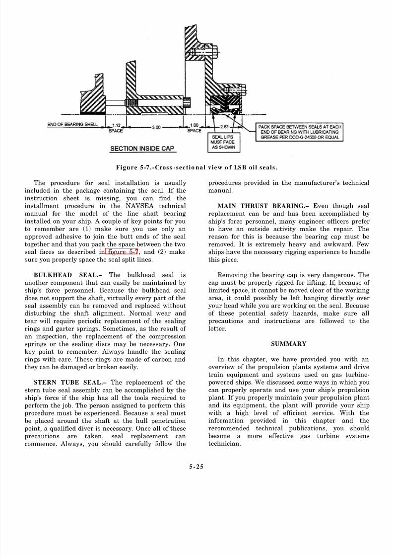
8/14/2019 US Navy Course NAVEDTRA 14115 - Gas Turbine Systems Technician Mechanical) 2
http://slidepdf.com/reader/full/us-navy-course-navedtra-14115-gas-turbine-systems-technician-mechanical 161/349
Figure 5-7.-Cross -sectio nal view o f LSB oi l seals .
The procedure for seal installation is usuallyincluded in the package containing the seal. If the
instruction sheet is missing, you can find theinstallment procedure in the NAVSEA technicalmanual for the model of the line shaft bearing
installed on your ship. A couple of key points for youto remember are (1) make sure you use only an
approved adhesive to join the butt ends of the sealtogether and that you pack the space between the twoseal faces as described in figure 5-7, and (2) make
sure you properly space the seal split lines.
BULKHEAD SEAL.– The bulkhead seal is
another component that can easily be maintained by
ship’s force personnel. Because the bulkhead sealdoes not support the shaft, virtually every part of theseal assembly can be removed and replaced withoutdisturbing the shaft alignment. Normal wear and
tear will require periodic replacement of the sealingrings and garter springs. Sometimes, as the result of
an inspection, the replacement of the compressionsprings or the sealing discs may be necessary. Onekey point to remember: Always handle the sealing
rings with care. These rings are made of carbon andthey can be damaged or broken easily.
STERN TUBE SEAL.– The replacement of the
stern tube seal assembly can be accomplished by theship’s force if the ship has all the tools required toperform the job. The person assigned to perform thisprocedure must be experienced. Because a seal must
be placed around the shaft at the hull penetrationpoint, a qualified diver is necessary. Once all of these
precautions are taken, seal replacement cancommence. Always, you should carefully follow the
procedures provided in the manufacturer’s technicalmanual.
MAIN THRUST BEARING.– Even though seal
replacement can be and has been accomplished by
ship’s force personnel, many engineer officers preferto have an outside activity make the repair. Thereason for this is because the bearing cap must be
removed. It is extremely heavy and awkward. Fewships have the necessary rigging experience to handle
this piece.
Removing the bearing cap is very dangerous. Thecap must be properly rigged for lifting. If, because of
limited space, it cannot be moved clear of the workingarea, it could possibly be left hanging directly overyour head while you arc working on the seal. Because
of these potential safety hazards, make sure allprecautions and instructions are followed to theletter.
SUMMARY
In this chapter, we have provided you with anoverview of the propulsion plants systems and drive
train equipment and systems used on gas turbine-powered ships. We discussed some ways in which you
can properly operate and use your ship’s propulsionplant. If you properly maintain your propulsion plantand its equipment, the plant will provide your ship
with a high level of efficient service. With theinformation provided in this chapter and the
recommended technical publications, you shouldbecome a more effective gas turbine systemstechnician.
5-25

8/14/2019 US Navy Course NAVEDTRA 14115 - Gas Turbine Systems Technician Mechanical) 2
http://slidepdf.com/reader/full/us-navy-course-navedtra-14115-gas-turbine-systems-technician-mechanical 162/349

8/14/2019 US Navy Course NAVEDTRA 14115 - Gas Turbine Systems Technician Mechanical) 2
http://slidepdf.com/reader/full/us-navy-course-navedtra-14115-gas-turbine-systems-technician-mechanical 163/349
CHAPTER 6
LCAC AND PHM PROPULSION SYSTEMS
The GSMs assigned to landing craft, air cushion
(LCAC) vessels and patrol combatant missile
(hydrofoil) (PHM) class ships are responsible for the
upkeep and maintenance of the propulsion and electric
plant control systems. If you are assigned to an LCACor a PHM, the watches you will stand will be different
from those on the DD-963, DDG-993, DDG-51, CG-47,
and FPG-7 class ships. In this chapter you will read
about some of these differences and the associated
responsibilities you may be expected to assume.
After reading this chapter, you should be familiar
with the operation of the engineering plant equipment
on the LCAC and PHM class ships. The information
presented in this TRAMAN is designed only to
familiarize you with the equipment on these ships. (In
chapter 7, we will discuss the electric plants for these
ships.) Remember, you should always use the
appropriate EOSS and PQS to qualify for a particular
watch station.
After reading this chapter and completing the
associated self-study questions in the NRTV, you should
have acquired enough knowledge to begin qualifying at
the individual watch stations on board these ships. Even
though you may never be assigned to an LCAC or PHM,
the information in this chapter should familiarize you
enough with the equipment to help you advance in the
GS rating. As you become more senior in the GS rating,
you may find yourself assigned to an LCAC or PHMclass ship, or to one of their maintenance depots. In
either case, this indoctrination could help you begin your
qualifications.
LANDING CRAFT, AIR CUSHION
The LCAC is a high-speed, ship-to-shore,
over-the-beach vehicle that will deliver a 60-ton payload
to the ground elements of a Marine amphibious force. It
provides the Navy and Marine Corps with high-speed
delivery capabilities to support amphibious operations.
The LCAC is an air cushion vehicle that is powered
by four AVCO Lycoming TF40B marine gas turbines
that provide a total of 15,820 horsepower (hp). Two
shrouded reversible pitch propellers provide forward
and reverse motion. The air cushion on which the craft
rides is created by four double-entry fans. These fans are
63 inches in diameter, providing the desired amount of
airflow. The steering system consists of two rotatable
bow thrusters and two aerodynamic rudders. Figure 6-1
is an illustration of an LCAC craft.
The LCAC engineering plant consists of
propulsion, lift, and control systems. The plant is
operated by the craft engineer/assistant operator while
the craft is underway. There are no traditional watches
as these limited endurance craft carry only enough
personnel to man the operating stations. The crew
consists of an operator, craft engineer/assistant
operator, navigator, load master, and deck hand/
engineer. This small crew is completely responsible for
underway operations, and embarkation and dis-
embarkation of troops and supplies. The only GS is the
craft engineer/assistant operator.
AVCO LYCOMING TF40B GAS
TURBINE ENGINE
The AVCO Lycoming TF40B gas turbine engine is
the major propulsion plant for the LCAC. As a GSM,
you will come into contact with the TF40B if you are
assigned to an LCAC or to one of its maintenance
depots.
There are four TF40B engines on the LCAC, two
on the port side and two on the starboard side. These
engines are the power sources that drive the lift fans,propellers, and forward and aft gearboxes. In the
following paragraphs, we will take a look at the TF40B
in terms of its design and normal operating
characteristics. Later in this chapter, we will take a look
at the control and other systems for its functions.
DESIGN AND OPERATION
The TF40B is a direct-drive, high-speed turbine
consisting of a 2-stage, free-power turbine and a
combination 7-stage, axial-centrifugal compressor
driven by a 2-stage, axial-flow turbine. It also
incorporates a reverse-flow, annular-type atomizing
combustor chamber assembly, oil cooler assembly,
topmounted accessory gearbox module, and an integral
lubrication system. The major sections of the TF40B are
shown in figure 6-2.
6-1

8/14/2019 US Navy Course NAVEDTRA 14115 - Gas Turbine Systems Technician Mechanical) 2
http://slidepdf.com/reader/full/us-navy-course-navedtra-14115-gas-turbine-systems-technician-mechanical 164/349
6-2

8/14/2019 US Navy Course NAVEDTRA 14115 - Gas Turbine Systems Technician Mechanical) 2
http://slidepdf.com/reader/full/us-navy-course-navedtra-14115-gas-turbine-systems-technician-mechanical 165/349
6-3

8/14/2019 US Navy Course NAVEDTRA 14115 - Gas Turbine Systems Technician Mechanical) 2
http://slidepdf.com/reader/full/us-navy-course-navedtra-14115-gas-turbine-systems-technician-mechanical 166/349
Figure 6-3.-Operation and primary airflow of TF40B gas turbine engine (LCAC).
Components and Assemblies
As you study figure 6-2, notice how the TF40B isbasically composed of two major sections: (1) the
output group assembly and (2) the power producergroup. The power producer group includes the gasproducer module and the combustor and the power
turbine assembly. The output group assembly
includes the accessory gearbox module, inlet housingmodule, and sump module. The power producer groupprovides a reverse annular flow path for air and hotgases. (See fig. 6-3.) The compressor rotor assembly is
directly connected to the first and second gasproducer disk assemblies. The fourth turbine rotor
disk assembly is directly connected to the powerturbine integral third turbine wheel disk shaftassembly. This assembly, which runs inside of the
compressor shaft, is splined to the power output shaftassembly. The power output shaft assembly is located
at the forward end of the engine. Its speed is equal topower turbine speed. Externally, the power outputgroup assembly provides mounting pads for several
accessories and components required for engineoperation.
Notice how the two major sections of the TF40Bare structurally interdependent. Working together asan operating unit, they provide an annular flow pathfor the air or hot gases, support internal rotating
systems, and provide external attaching capabilitiesfor components and accessories required for engine
operation. An important advantage of this design isthat it allows for the removal and installation ofengine modules. This
6-4

8/14/2019 US Navy Course NAVEDTRA 14115 - Gas Turbine Systems Technician Mechanical) 2
http://slidepdf.com/reader/full/us-navy-course-navedtra-14115-gas-turbine-systems-technician-mechanical 167/349
means you are able to make repairs and replace a variety
of engine-related components without having to ship the
complete engine to a depot repair facility.
O p e r a t i o n
Study figure 6-3 as you read about the operation of
the TF40B. The compressor rotor assembly is turned by
the air starting system as air enters the inlet housing
module. The inlet air is directed into the compressor
rotor assembly and is compressed. The compressed airthen flows through the air diffuser assembly and into the
atomizing combustor chamber assembly. When the
engine reaches 2,246 rpm, the fuel valve assembly and
fuel flow divider allow metered main fuel to flow to the
28 main fuel injection nozzles. The air mixes with fuel
from the fuel injection nozzles to form a combustible
mixture. Two igniter assemblies provide spark and
ignite the mixture, creating the hot, expanding gases
which are discharged through the turbine section. Some
energy from the hot gases drives the two gas producer
disk assemblies which, in turn, drive the compressor
rotor assembly. The remaining energy from the hot gasesdrives the integral third turbine wheel shaft assembly
and fourth turbine rotor disk assembly which, in turn,
drive the power output shaft assembly.
Systems
The operation of the TF40B is supported by the
following major systems:
1. Electrical control system
2. Ignition system
3. Engine gas temperature (EGT) system4. Speed sensing system
5. Fuel system
6. Lubrication system
7. Electronic control system
8. Air system
In the following paragraphs, we will give you a brief
overview of these systems. You will need to become
familiar with the fundamental systems of this engine
before you read about your general maintenance
responsibilities. For detailed descriptions of these
systems, you should consult the appropriate technical
manuals.
ELECTRICAL CONTROL SYSTEM.– The
electrical control system is energized by a separate 24-
to 28-V dc ungrounded two-wire power source. The
system consists of engine-mounted accessories and
sensors, an electronic control system, and panel-
mounted controls and indicators. AU engine harnesses
are designed to withstand salt spray, sand, dust, fungi,
vibrations, immersion during washdown and steam
cleaning, and fuel and oil residues. The connector ends
are molded for wiring integrity and suitable strain relief.
The cable assemblies provide electrical continuity
between the engine accessories and engine interfaces.
All molded ends of the harness assemblies are stamped
with their respective plug numbers, making it easier foryou to locate and identify these assemblies in the
appropriate engine electrical control system wiring
schematic.
CAUTION
System ground is isolated and should not be
connected to frame ground.
IGNITION SYSTEM.– The ignition system is
used for start procedures only. It consists of a single-box,high-energy, capacitor-discharge ignition exciter that is
used with two ignition leads and two shunted surface
gap-type igniter assemblies.
Ignition Exciter.– The ignition exciter is designed
to operate in ambient temperatures of -30° to 250°F
(-34° to 121°C). It uses an input voltage of 16 to
30 V dc and will produce an output voltage of at
least 2,400 V at the igniter assemblies. Its duty cycle is
2 minutes on, 3 minutes off, 2 minutes on, 23 minutes
off.
Ignition Leads and Igniter Assemblies.– Theignition leads will operate in ambient air temperatures
of –30° to 500°F (–34° to 260°C). Both the ignition
leads and the igniter assemblies are designed to operate
in a marine environment.
ENGINE GAS TEMPERATURE SYSTEM.–
The EGT system works with the electronic control
system to sense turbine speeds and provide monitoring
information. First, the gas temperature is sensed by a
chromel-alumel parallel thermocouple averaging
arrangement. Then, it is biased by the air inlet
temperature sensing device assembly and finally
applied to the electronic control system for automaticmonitoring purposes.
SPEED SENSING SYSTEM.– The gas producer
(N1) and power turbine (N2) speeds are sensed by theirmagnetic pickups located nearby. The N 1 speed
magnetic pickup is located on the rear face of the
6-5

8/14/2019 US Navy Course NAVEDTRA 14115 - Gas Turbine Systems Technician Mechanical) 2
http://slidepdf.com/reader/full/us-navy-course-navedtra-14115-gas-turbine-systems-technician-mechanical 168/349
accessory gearbox module. The N2 speed magnetic
pickup is located inside the inlet housing. The pickup
signals, fed to the electronic control system, provide
visual speed readout signals along with engine control
and governing functions.
FUEL SYSTEM.– The major function of the
engine fuel system is to provide fuel to the atomizing
combustor chamber assembly at a specific, regulated
flow rate to ensure optimum engine performance at all
stages of operation. The basic components of the fuel
system are the fuel valve assembly (consisting of the
fuel valve, limiter, and actuator), connecting hoses,
main fuel and redundant valves, oil cooler assembly,
high-pressure fuel filter, fuel flow divider, fuel return
solenoid valve, fuel manifolds, and 28 fuel injection
nozzles.
Filtered fuel flows from the fuel valve assembly. It
then flows through the fuel solenoid valve, oil cooler
assembly, and redundant fuel solenoid valve. Next, it
flows into the fuel flow divider that provides primary
and secondary fuel flow to the fuel injection nozzles,
which deliver the fuel into the atomizing combustor
chamber assembly.
A pressure-actuated combustion chamber drain
valve assembly is mounted on the bottom perimeter of
the atomizing combustor housing assembly. In the event
of a shutdown, an aborted start, or engine flameout, this
assembly automatically drains residual fuel from the
combustion area. The fuel return solenoid valve
automatically reduces fuel flow to reduce the EGT
during the start sequence only if EGT rises to the
warning offset set point.
NOTE: This can also be done manually during the
start sequence or at any time during engine operation.
The operator positions the START/STOP switch to the
START position and holds it there.
The high-pressure fuel filter assembly consists of a
throwaway 10-micron filter element and ahead and case
assembly. The fuel filter has a rated flow of 12 gallons
per minute.
The head assembly incorporates a stainless-steel
bypass relief valve that opens at 45 to 55 psid and a
differential pressure indicator that actuates a red pop-up
button at 30 to 40 psid to indicate the filter is clogged.The pop-up indicator has a thermal lockout feature for
temperatures from 20° to 50°F (–7° to 10°C) to prevent
false indications in extremely cold conditions. If the
pop-up indicator actuates, you must flush the filter case.
You must also replace the filter when you reset the
pop-up button.
LUBRICATION SYSTEM.– The TF40B lubri-
cation system consists of the sump module, an accessory
gearbox module driven lube and scavenge pump, an
engine-mounted oil cooler assembly, the necessary
piping, and a lube filter assembly. The lube and scavenge
pump draws oil from the sump module and delivers it to
the oil cooler assembly. The oil then flows from the oil
cooler assembly into the oil inlet port where it surrounds
the lube filter assembly, which contains a 7-micron
element. The oil flows through the filter, up through thecore, and out of the oil outlet port to the oil distribution
block. From here, the oil flows into the accessory
gearbox module and inlet housing module to lubricate
the forward internal bearings and gears. If the 7-micron
filter becomes clogged, the oil is bypassed. Located in
the head assembly is a differential oil pressure switch,
which actuates at 13 to 19 psid, and a bypass valve,
which opens at 21 to 29 psid if the filter becomes
clogged and can no longer function. The differential oil
pressure switch will actuate just before bypass to
illuminate an oil filter warning light on the instrument
panel. This switch is mechanically locked until oiltemperature reaches 115° to 155°F (46° to 68°C) to
provide for warmup in cold weather conditions.
External piping in the lubrication system also
supplies filtered oil to the power output shaft assembly
and to the compressor and power turbine bearings. A
scavenge oil pump mounted on the accessory gearbox
is integral to the lube and scavenge pump. The scavenge
oil pump provides positive drainage of the No. 4 and
No. 5 bearing scavenge oil through external oil hose
assemblies and the lube monitor assembly to the top of
the inlet housing module. An external oil hose assembly
provides gravity drainage of the No. 2 bearing scavenge
oil from the combustor and power turbine assembly to
the sump module. The scavenge oil drains internally by
gravity from all the other components through the
accessory gearbox module, inlet housing module, and
compressor housing to the sump module. Electronic
chip indicators in the No. 4 and No. 5 bearing oil
scavenge lines and in the sump module initiate warnings
in case of metallic chip accumulation in the lubricating
oil.
ELECTRONIC CONTROL SYSTEM.– The
TF40B electronic control system provides for automaticstart and power control and monitoring of engine
operations. It also sequences automatic shutdown of the
engine.
The electronic control system consists of a modular
control box assembly, instrument and control panel, the
associated wiring and cabling, and sensing and
6-6

8/14/2019 US Navy Course NAVEDTRA 14115 - Gas Turbine Systems Technician Mechanical) 2
http://slidepdf.com/reader/full/us-navy-course-navedtra-14115-gas-turbine-systems-technician-mechanical 169/349
Figure 6-4.-LCAC operator station c om man d mo dule.
indicating devices for engine pressure, temperature,
and speed. Visual indications of engine sequencing,EGT, speed, and lubrication conditions are providedon the command station instrument and control panel
and on the modular control box assembly modules.
The modular control box assembly is a solid-statemodular unit encased in a splashproof enclosure. Thisassembly contains the system power supply,
temperature monitor, GP speed monitor, PT speedmonitor, engine sequence, malfunction monitor, fuel
control, isolation analog, and utility panel modules.
During the start cycle, a maximum current drain
of approximately 10 amperes at 24 V dc is required.This current requirement is reduced to approximately
6 amperes after the start sequence is completed.
AIR SYSTEM.– We will discuss the TF40B air
system in terms of its major sections and generalfunctions.
Air Starter System.– The starter is mounted on
a pad on the accessory gearbox module in the poweroutput section. Air enters the inlet housing module
through ports on each side of the inlet housingassembly. The inlet air is then powered by 37 to 46
psi through the air start valve and directed to thecompressor rotor assembly where it is compressed.
The compressed air then flows through the airdiffuser assembly and into the combustion chamber.
After the engine has started, a control switch
terminates starter operation. For a more detaileddiscussion of these components, refer to the specifictechnical manual for this system.
Air Bleed Syst em .– The air bleed system consists
of an air bleed valve assembly that is located on the
air bleed manifold housing. The air bleed manifoldhousing is located on the combustor housing
assembly. The air bleed valve is spring loaded. It is
modulated by P4 air from the combustor. The functionof the air bleed system is to provide a margin for
compressor surge. This function protects the enginewhile it is accelerating to maximum power. The air is
vented overboard through ports in a screened flangein the assembly.
LCAC CONTROL S YSTEMS
In the following paragraphs, we will describe the
basic physical and functional characteristics of theLCAC control systems. The LCAC control systems
include all the systems and controls the operatorneeds to maneuver the craft. Maneuvering an LCACbasically consists of controlling the craft’s direction,
speed, and cushion.
The LCAC control systems are divided into thefollowing subsystems:
1. Steering control system
2. Propeller pitch control system 3. Lift fan control system
4. AVCO Lycoming TF40B engine control system
5. Command and control keyboard
6. Rate of turn system
7. Outside air temperature system 8. Speed/sideslip indicator
These subsystems are controlled by the operator in
the LCAC operator station command module or theoperator in the engineer control station. Figure 6-4shows the physical arrangement of a typical LCAC
6 -7
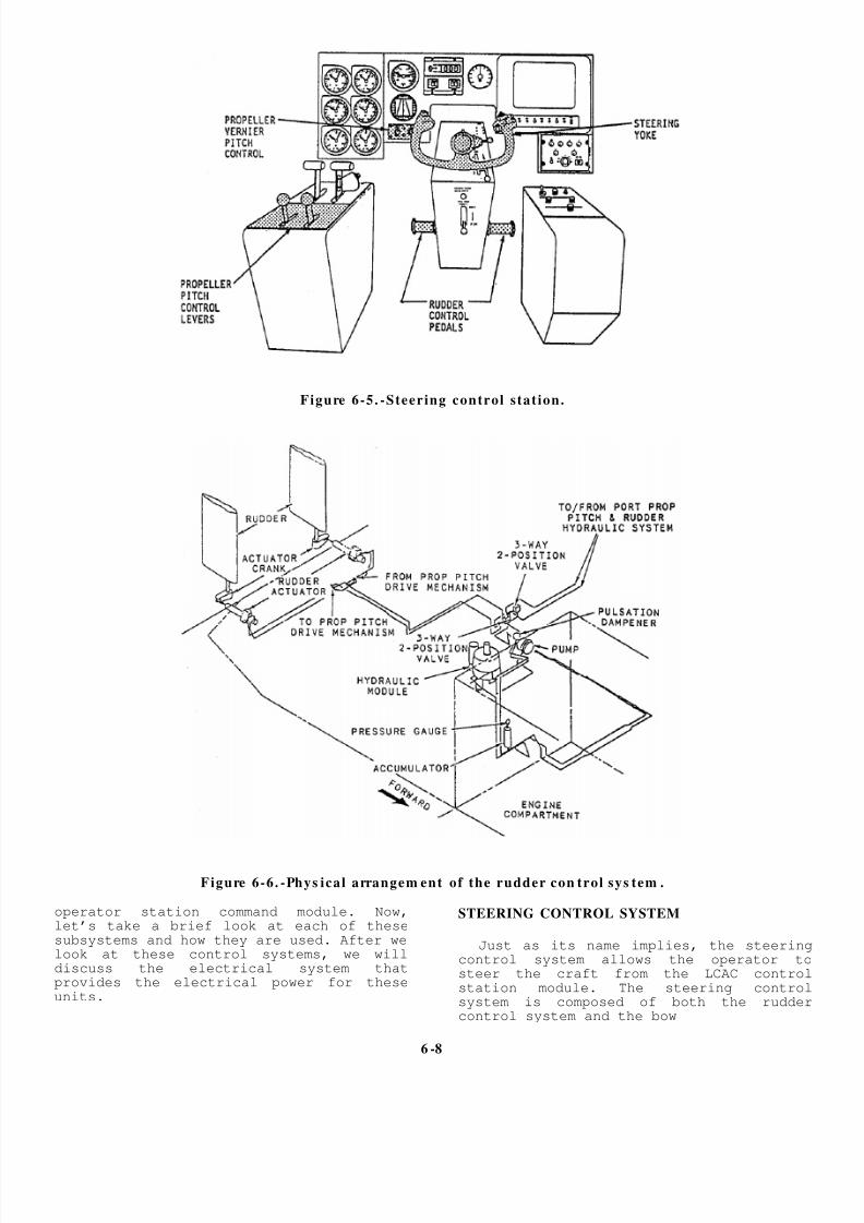
8/14/2019 US Navy Course NAVEDTRA 14115 - Gas Turbine Systems Technician Mechanical) 2
http://slidepdf.com/reader/full/us-navy-course-navedtra-14115-gas-turbine-systems-technician-mechanical 170/349
Figure 6-5. -Steering control station.
Figure 6-6. -Phys ical arrangem ent of the rudder con trol sys tem .
operator station command module. Now,let’s take a brief look at each of thesesubsystems and how they are used. After welook at these control systems, we willdiscuss the electrical system thatprovides the electrical power for theseunits.
STEERING CONTROL SYSTEM
Just as its name implies, the steeringcontrol system allows the operator tosteer the craft from the LCAC controlstation module. The steering controlsystem is composed of both the ruddercontrol system and the bow
6 -8

8/14/2019 US Navy Course NAVEDTRA 14115 - Gas Turbine Systems Technician Mechanical) 2
http://slidepdf.com/reader/full/us-navy-course-navedtra-14115-gas-turbine-systems-technician-mechanical 171/349
Figure 6-7 .-Rudder pedals.
thruster control system and the associatedoperational controls, as shown in the shaded areas of
figure 6-5. In the following paragraphs, we willbriefly describe the major assemblies and componentsand their functions within the design and operation
of the craft control system.
Rudder Cont rol Syst em
The function of the rudder control system is toprovide the capability for turning power at the sternof the craft. Figure 6-6 shows the basic configuration
of the rudder control system. (Study and comparefigs. 6-1 and 6-6.) Study figure 6-6 as you read about
the components and their functions.
There are two rudders mounted vertically across
the trailing edge of each propeller duct. The ruddersare used with the bow thrusters to provide turning
capability. The function of the rudders is to deflectpropeller slipstream which, in turn, provides aturning force at the stern of the craft.
Operation of the rudder control system is based on
hydraulic pressure. In fact, a hydraulic pressure
system supplies power to both the rudder controlsystem and the propeller pitch control system. There
is a separate hydraulic system for each side of thecraft, consisting of pumps, valves, actuators, and
piping. The control station operator controls therudders by moving the rudder control pedals forwardor aft, as required. Movement of a rudder control
pedal is converted into an electrical signal. Theelectric signal, in turn, controls a hydraulic position
actuator that moves the rudder for that side of thecraft to the selected position. Figure 6-5 shows the
location of the rudder control pedals at the steeringcontrol station. Figure 6-7 shows a side view of the
rudder pedal assembly.
PEDAL CONTROLS.– The control station
operator moves the rudders by operating the twopedals on the rudder control assembly. (See shadedareas of figs. 6-5 and 6-7.) The rudder pedals pivot on
an axle to allow the operator to move the rudders inboth directions. To move the rudders to full port or
full starboard, the operator pushes the port orstarboard pedal forward. This action causes apotentiometer to send a negative (port) or positive
(starboard) electrical signal through the controlsystem electronic package (CSEP) and to the rudder
actuator, thereby causing the rudder to move left orright as directed. The pedal controls are spring-loaded to allow them to return to the neutral position
after the rudder has moved to the commandedposition.
CSEP AND RUDDER INTERFACE ASSEM-
BLY.– The function of the CSEP is to control and
send the command signals initiated by the operator inthe control station to the various components in thecraft control system. The LCAC has two identical
CSEPs, labeled CSEP A and CSEP B. Each CSEP hasa single circuit specifically for rudder control. A
rudder control signal initiated by the control stationoperator will be routed through one of these channelsto the rudder
6 -9

8/14/2019 US Navy Course NAVEDTRA 14115 - Gas Turbine Systems Technician Mechanical) 2
http://slidepdf.com/reader/full/us-navy-course-navedtra-14115-gas-turbine-systems-technician-mechanical 172/349
Figure 6-8.-Physical arrangement of the LCAC bow thruster control system.
control components. The operator can use either
CSEP A or CSEP B to route a rudder control signal.
RUDDER POSITION DRIVE ASSEMBLY.–
The rudder position drive assembly contains a valvecoil, hydraulic drive servomotor, and feedback
potentiometer. The CSEP sends an electrical drivesignal to the electric drive servomotor through the
valve coil to position the rudders. As the rudders are
positioned, a feedback signal goes to the CSEP. Whenthe feedback signal is equal and opposite to the drive
signal, the rudders are in the desired position.
RUDDER BLADES.– The craft’s two rudders arc
mounted vertically across the trailing edge of each
propeller shroud. The rudder blades are broad, flat,aerodynamic, movable devices that measure 10.4 feetlong and 2.3 feet wide. The rudder blades allow the
operator to maneuver the craft by deflecting thepropeller slipstream at various angles.
RUDDER CHANNEL SELECTOR SWITCH.–
The rudder channel selector switch is located on the
command and control (C&C) keyboard at theengineer station. This
switch, labeled RUDDER A/B, allows the operator to
choose between channels of the CSEP in case of an
emergency or system fault.
RUDDER CONTROL SYSTEM
INDICATORS.– Indicators are provided on the
alarm and monitor system (AMS) cathode ray tube(CRT) display monitor, The display monitor is locatedat the engineer control station. The indicators include
the following:
• Rudder control failure
• Port and starboard hydraulic reservoir low
• Port and starboard hydraulic pressure low
Bow Thruster Control System
The purpose of the bow thruster control system isto allow the operator to turn the bow of the craft and
to move the craft in close places. This system isextremely useful when the operator must dock andundock the LCAC in the dry well of the support ship
6-10

8/14/2019 US Navy Course NAVEDTRA 14115 - Gas Turbine Systems Technician Mechanical) 2
http://slidepdf.com/reader/full/us-navy-course-navedtra-14115-gas-turbine-systems-technician-mechanical 173/349
Figure 6 -9 . -Steering yoke and con trols .
and assembly port and one The bow thruster controlsystem consists of two bow thrusters (one starboard),the steering yoke assembly, and the associated
electrical and hydraulic operating mechanism. Thephysical arrangement of these components and
assemblies is shown in figure 6-8. The bow thrustersprovide thrust for the craft. The controls andoperating mechanisms allow the control station
operator to control the rotation of the bow thrustersto achieve the desired directional thrust. Basically,
the control station operator uses the steering yoke inthe steering control assembly to turn the craft rightor left, respectively. Turning the yoke left causes the
craft to turn left, while turning the yoke right causesthe craft to turn right. The steering yoke contains
potentiometers that detect yoke movement and sendelectrical signals through the CSEP to the hydraulicoperating mechanism.
Like the rudder control system, the bow thruster
control system uses hydraulic power to turn the bowthrusters. A system of pumps, flow control valves,
and piping supplies hydraulic power to the bowthruster wheel units and lift fan cushion vanes.When the operator turns the yoke, electrical signals
are generated and routed through the CSEP to thebow thruster actuators. The basic components of thebow thruster control system are the steering yoke,
forward/reverse switch, bow thruster drivemechanism, turning vanes, channel selector switch,
and indicators.
STEERING YOKE.– The relative location of the
steering yoke in the operator control station is shownin f igure 6-5. The components and controls of the
steering yoke are shown in greater detail in figure 6-9. The operator at the steering control station usesthe steering yoke to control the direction of the bow
thrusters. The steering yoke will turn 45° in eitherdirection.
FORWARD/ REVERSE SWITCH.– This switch
allows the operator to select the direction in which
the bow thrusters apply thrust. The switch is locatedon the steering yoke. (See fig. 6-9) The switch allows
an electrical signal to pass through the CSEP to thebow thruster drive mechanism to position the bowthruster as ordered.
BOW THRUSTER DRIVE MECHANISM.– The
bow thruster drive mechanism works to move the
bow thrusters to the position ordered by the operator.When the yoke is turned, it positions a potentiometer
and sends an electrical signal to a mode and bias
amplifier in the CSEP. The signal then goes to thebow thruster drive mechanism to position the bow
thruster. The bow thruster turns, positioning afeedback potentiometer, and sends a feedback signal
to the CSEP. When the feedback signal equals thecommand signal, the bow thruster is in the desiredposition.
6-11

8/14/2019 US Navy Course NAVEDTRA 14115 - Gas Turbine Systems Technician Mechanical) 2
http://slidepdf.com/reader/full/us-navy-course-navedtra-14115-gas-turbine-systems-technician-mechanical 174/349
Figure 6-1 0.-Bow thruster turning vanes.
BOW THRUSTER TURNING VANES.– The
purpose of the turning vanes is to direct airflowtoward and out of the bow thrusters. Figure 6-10
shows the configuration of the bow thruster turning vanes. Notice how the fixed vanes are attached into
the air duct of the lift fan module and into the bow
thruster volute. This design allows the airflow toreach the bow thrusters with a minimum of
turbulence inside the volute and air duct.
BOW THRUSTER CHANNEL SELECTOR
SWITCH.– The bow thruster channel selector switch
is located on the C&C keyboard at the engineer
station. This switch, labeled BOW THRUSTER A/B,allows the operator to choose between channels of theCSEP in case of an emergency or system fault.
BOW THRUSTER INDICATORS.– The function
of the bow thruster control system indicators is to
inform the operator of existing operating conditionsand alarm conditions concerning the following areas:
• Bow thruster control failure
• Port and starboard hydraulic reservoir low
• Port and starboard hydraulic pressure low
Now that you have read about the most important
components of the steering control system, let’s take alook at an associated system that is supplied by thesame hydraulic power source–the propeller pitch
control system.
PROPELLER PITCH CONTROL SYSTEM
The purpose of the propeller pitch control system
is to allow the operator to control the speed anddirection of the LCAC by changing propeller pitch.
The LCAC propeller assembly is capable of bothforward and reverse pitch. The greater the angle ofpitch, the faster the craft will move.
The propeller pitch control system is composed of
the yoke assembly, propeller pitch indicator, a controlunit, propeller pitch control levers, potentiometers,
and amplifiers. The control station operator controls
the propeller pitch by using the two levers on the left-hand console and the in/out movement of the yoke.
Pushing the yoke in or pulling it out will sendelectrical signals to the electrohydraulic servo valve
and actuator, allowing the operator to control thepitch of the propellers. An indicator at the operatorstation provides an indication of propeller pitch.
Figure 6-5 shows the physical location of thepropeller pitch controls in the operator station. Let’stalk shout some of these controls and how they work.
6-12

8/14/2019 US Navy Course NAVEDTRA 14115 - Gas Turbine Systems Technician Mechanical) 2
http://slidepdf.com/reader/full/us-navy-course-navedtra-14115-gas-turbine-systems-technician-mechanical 175/349
Figure 6-11.-Propeller pitch control levers.
Propeller Pitch Control Levers
The function of the propeller pitch control
levers is to allow the operator to control the pitchof the propellers. By controlling the pitch of the
propellers, the operator can control the speed anddirection of the craft. Figure 6-11 shows a detailed
view of the propeller pitch control levers. Each
control lever has a detent stop at zero degrees of propeller pitch with adjustable mechanical stops at
both ends. The propellers are adjustable from +40°to -30°.
Propeller Pitch Drive Assembly
The propeller pitch drive works to position the
propeller to the position ordered by the operator.When the operator moves the control levers, anelectrical signal range is produced and sent to the
CSEP where it is amplified. From the CSEP, the
amplified signal is sent to the propeller pitch drivemechanism. The propeller pitch drive mechanismturns the propeller, causing a feedbackpotentiometer to send a signal to the CSEP. When
the feedback signal equals the command signal,the propeller is in the ordered position, The
propeller pitch drive mechanism can also betriggered by the vernier pitch control circuit wewill describe in the following paragraph.
Vernier Pitch Control Switch
The function of the vernier pitch controlswitch is to allow the operator to select thecontrol source, or combination of control sources,
to control propeller pitch. When the vernierpitch control switch is in the OFF position, the
operator can control propeller pitch only bymoving the control levers. When the vernier
pitch control switch is ON, the operator cancontrol propeller pitch by using both the controllevers and the in-and-out movement of the yoke.
The operator uses the control levers to set themidrange for the yoke propeller pitch controlrange.
Propeller Pitch Selector Switch
The propeller pitch channel selector switch islocated on the C&C keyboard at the engineer
station. This switch, labeled PROP A/B, allows theoperator to choose between channels of the CSEP
in case of an emergency or system fault.
Propeller Pitch Control System Indicators
The function of the propeller pitch indicatorsis to inform the operator of existing conditions. Theoperator uses this information to move the craft as
effectively and safely as possible. This subsysteminforms the operator of the following conditions:
• Propeller control failure
• Port and starboard hydraulic reservoir low
• Port and starboard hydraulic pressure low
• Propeller pitch
These indicators are provided at both the operator
control station and the engineer control station.
You have just read about the steering controlsystem and the propeller pitch control system.Now, let’s take a look at another system that works
with these two systems to allow the operator tomaneuver the craft.
LIFT FAN CONTROL SYSTEM
The lift fan control system allows the engineer
to control the airflow to the cushion of the craft. An emergency dump switch is provided at the
operator control station to allow the operator tostop the craft in an emergency by taking it off theair cushion.
6-13
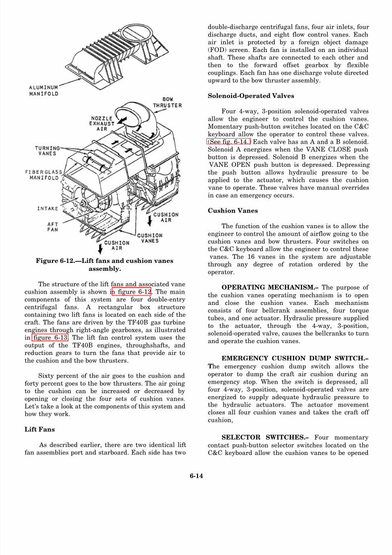
8/14/2019 US Navy Course NAVEDTRA 14115 - Gas Turbine Systems Technician Mechanical) 2
http://slidepdf.com/reader/full/us-navy-course-navedtra-14115-gas-turbine-systems-technician-mechanical 176/349
Figure 6-12.—Lift fans and cushion vanes
assembly.
The structure of the lift fans and associated vane
cushion assembly is shown in figure 6-12. The maincomponents of this system are four double-entry
centrifugal fans. A rectangular box structurecontaining two lift fans is located on each side of the
craft. The fans are driven by the TF40B gas turbineengines through right-angle gearboxes, as illustratedin figure 6-13. The lift fan control system uses the
output of the TF40B engines, throughshafts, andreduction gears to turn the fans that provide air to
the cushion and the bow thrusters.
Sixty percent of the air goes to the cushion and
forty percent goes to the bow thrusters. The air going
to the cushion can be increased or decreased byopening or closing the four sets of cushion vanes.Let’s take a look at the components of this system andhow they work.
Lift Fans
As described earlier, there are two identical liftfan assemblies port and starboard. Each side has two
double-discharge centrifugal fans, four air inlets, four
discharge ducts, and eight flow control vanes. Eachair inlet is protected by a foreign object damage
(FOD) screen. Each fan is installed on an individualshaft. These shafts are connected to each other andthen to the forward offset gearbox by flexible
couplings. Each fan has one discharge volute directedupward to the bow thruster assembly.
Solenoid-Operated Valves
Four 4-way, 3-position solenoid-operated valves
allow the engineer to control the cushion vanes.Momentary push-button switches located on the C&C
keyboard allow the operator to control these valves.(See fig. 6-14.) Each valve has an A and a B solenoid.Solenoid A energizes when the VANE CLOSE push
button is depressed. Solenoid B energizes when the VANE OPEN push button is depressed. Depressing
the push button allows hydraulic pressure to beapplied to the actuator, which causes the cushion
vane to operate. These valves have manual overrides
in case an emergency occurs.
Cushion Vanes
The function of the cushion vanes is to allow the
engineer to control the amount of airflow going to thecushion vanes and bow thrusters. Four switches onthe C&C keyboard allow the engineer to control these
vanes. The 16 vanes in the system are adjustablethrough any degree of rotation ordered by the
operator.
OPERATING MECHANISM.– The purpose of
the cushion vanes operating mechanism is to open
and close the cushion vanes. Each mechanismconsists of four bellcrank assemblies, four torque
tubes, and one actuator. Hydraulic pressure suppliedto the actuator, through the 4-way, 3-position,solenoid-operated valve, causes the bellcranks to turn
and operate the cushion vanes.
EMERGENCY CUSHION DUMP SWITCH.–
The emergency cushion dump switch allows the
operator to dump the craft air cushion during an
emergency stop. When the switch is depressed, all
four 4-way, 3-position, solenoid-operated valves areenergized to supply adequate hydraulic pressure tothe hydraulic actuators. The actuator movementcloses all four cushion vanes and takes the craft off
cushion,
SELECTOR SWITCHES.– Four momentary
contact push-button selector switches located on theC&C keyboard allow the cushion vanes to be opened
6-14

8/14/2019 US Navy Course NAVEDTRA 14115 - Gas Turbine Systems Technician Mechanical) 2
http://slidepdf.com/reader/full/us-navy-course-navedtra-14115-gas-turbine-systems-technician-mechanical 177/349
Figure 6-13.-TF40B propulsion and drive system arrangement.
Figure 6-14.-Command and control (C&C) keyboard.
6-15

8/14/2019 US Navy Course NAVEDTRA 14115 - Gas Turbine Systems Technician Mechanical) 2
http://slidepdf.com/reader/full/us-navy-course-navedtra-14115-gas-turbine-systems-technician-mechanical 178/349
and closed from the engineer station. These switches do
not use power from the CSEP.
INDICATORS.– The following indicators are
provided to inform the operator of the status of the
cushion vanes:
. Port and starboard cushion vane position (bar
graph)
. Port and starboard cushion vane digital position
The operator uses this information
effective movement of the craft.
LYCOMING TF40B ENGINE
CONTROL SYSTEM
to achieve the most
The TF40B engine control system provides the
operator with controls and indicators to operate the
engines and to move the craft effectively and safely. The
engine control system consists of the following five
control and indicator panels:
1. N1
2. N2
3. Engine balancing
4. Engine instrument
5. Engine start
The NI unit is the gas producer control unit. The N2 unit
is the power producer control unit. The engine balancing
control unit is combined with the N2 unit to balance the
power outputs of the four TF40B engines. The engine
instrument panel provides an analog indication of engine operating conditions. The engine start panel
gives the engineer or craft operator control of the engine
start and shutdown cycles.
The controls for the TF40B engine control system
are powered from two dc power panels and by signals
from the CSEP. The N2 and engine balance control
signals are combined through the CSEP. The NI control
signals are supplied with a positive-to-negative control
voltage range from the CSEP.
Now that you have read about the control and
indicator panels, let’s take a look at the gas turbineengines and their associated controls.
Gas Turbine Engines
As stated earlier, the four direct-drive, high-speed
TF40B gas turbine engines are located in pairs on the
port and starboard sides of the craft. The two-engine
assembly for each side of the craft consists of a 2-stage,
free-power turbine and a combination axial/centrifugal
compressor driven by a two-step, axial-flow turbine.
(Compare figs. 6-1 and 6-13.) Each of these assemblies
is the power source that drives the lift fans, propellers,
and forward and aft gearboxes for that side of the craft.
The lift fans and propellers are interconnected through
the drive train by offset and engine gearboxes. There is
a manual clutch provided on each power train to allow
the forward engine to be disconnected from the aftengine.
Engine Start/Stop Switches
The function of the TF40B engine start/stop
switches is to allow the operator to start and stop the
engines from the control station. Each engine has a
START/STOP switch and an OFF/IDLE/RUN master
switch. The START/STOP switches send signals to the
engine sequencing units, then to the respective engine
control box, to carry out the ordered function.
Engine Balancing Control Potentiometers
The function of the engine balancing control
potentiometers is to control the power output of each
engine to make sure the engines are balanced.
Gas Producer Controls
The gas producer controls (Nl) are used by the
engineer to set the speed of the engines. These controls
are located in the engineer control station. The primary
function of these controls is to allow the operator tocontrol the speed of the gas turbine engines and move
the craft.
Power Producer Controls
Like the gas producer controls, the primary function
of the pwer producer controls (Nz) is to allow the
operator to control the speed of the engines. When the
operator uses the power producer controls, a signal goes
to the CSEP and the correct engine control boxes to
control that engine’s speed.
Automatic Shutdown Normal/Override Switch
The automatic shutdown, normal/override switch
allows the craft operator to inhibit all automatic
shutdown features of the TF40B except an overspeed
condition. This switch allows the operator to control the
engines under battle conditions. This component was
6-16
8/14/2019 US Navy Course NAVEDTRA 14115 - Gas Turbine Systems Technician Mechanical) 2
http://slidepdf.com/reader/full/us-navy-course-navedtra-14115-gas-turbine-systems-technician-mechanical 179/349
built into the engine control system to provide maximum
safety for LCAC personnel.
Engine Control Channel Selector Switch
The function of the engine control channel selector
switch is to select which CSEP will be used for engine
control. The operator can select the desired channel by
using the ENGINE CNTL A/B switch located on the
C&C keyboard. his switch provides redundancy in
case of a system malfunction or an emergency.
Alarm and Monitor System Indicators
The function of the TF40B engine control AMS
indicators is to inform the operator of existing operating
conditions and any alarm condition that may affect craft
movement. The TF40B AMS includes the following
indicators:
l
l
l
l
l
l
l
l
l
l
l
l
l
l
l
l
l
l
These
Engine intake air filter alarm
Blow-in door open alarm
Lube oil filter alarm
Compartment hot alarm
Chip sump alarm
Chip bearing alarm
Low oil quantity alarm
Engines 1,2,3, and 4 ready to start
Engines 1,2, 3, and 4 sequence failure
Engines 1, 2, 3, and 4 degradation alarm and
percentage
Engines 1, 2, 3, and 4 lube oil temperature
Engines 1, 2,3, and 4 lube oil pressure
Engines 1, 2, 3, and 4 exhaust gas temperature
Engines 1, 2, 3, and 4 inlet temperature
Engines 1, 2, 3, and 4 inlet pressure
Engines 1, 2, 3, and 4 compressor pressure
NI, Engines 1,2,3, and 4
N2, Engines 1,2,3, and 4
indicators are provided at the engineer control
station. Refer to the appropriate technical manual for a
detailed functional description of these indicators.
COMMAND AND CONTROL KEYBOARD
The function of the C&C keyboard is to provide the
operator or engineer with a centralized means of control
for various craft functions. Each control function is
designated on an applicable keyboard switch. As shown
in views A and B of figure 6-14, the LCAC C&C
keyboard comes in two styles. The design represented
in view A is found on LCACS 1 through 14 and 24. The
design represented in view B is found on LCACs 25 andabove.
The C&C keyboard
five functional areas:
1. FUEL/DEFUEL
2. MISC
3. LUBE
4. ENGINE FEED
5. APU FEED
is divided into the following
In the following paragraphs, we will briefly discuss eachof these functions. Refer to figure 6-14 as you read about
these functional areas.
FUEL/DEFUEL Section
The FUEL/DEFUEL section contains the switches
the operator or engineer can use to control the fuel
transfer valves, defueling valves, and fuel transfer
pump.
MISC Section
The MISC (miscellaneous) section contains
switches that the operator or engineer can use to control
the application of 60-Hz electrical power, battery power,
and shore power to the craft. This section also has
switches the engineer can use to test the generators. It
also contains the CSEP channel switches for the bow
thrusters, rudders, and engine control system. The
cushion vanes and engine compartment ventilation fans
are also controlled from this section of the C&C
keyboard.
LUBE Section
The LUBE section contains the switches the
engineer can use to control the lube oil system valves.
There are four switches in this section, one for each lube
oil system valve.
6-17

8/14/2019 US Navy Course NAVEDTRA 14115 - Gas Turbine Systems Technician Mechanical) 2
http://slidepdf.com/reader/full/us-navy-course-navedtra-14115-gas-turbine-systems-technician-mechanical 180/349
Figure 6-15.-Rate of turn gyro system.
ENGINE FEED Section
The ENGINE FEED section contains theswitches that control fuel flow to the engines. This
section also contains the switches that control thefuel valves for the fuel tanks. The switches in this
section allow the operator to select the primary orsecondary fuel pump and control the main enginecoalescer drains. Other switches in this section allow
the engineer to test the automatic pump shiftingroutine. The CHIPZAP switch in this section allows
the operator to destroy small particles in thetransmission system and main engine sumps.
APU FEED Section
The auxiliary power unit (APU) FEED section
contains the switches that control the port andstarboard APU coalescer drains. The sump chip
detector alarm circuitry can be turned on and off from this section. Switches are also provided to bring400-Hz power from the aft switchboards to the
forward power panels.Located to the left of the C&C keyboard are
switches and knobs that control panel illuminations
(not shown). A push-button switch is provided to testthe AMS and C&C keyboard lighting.
RATE OF TURN SYSTEM
The function of the rate of turn system
is to provide an indication in degrees of the
craft ’s rate of turn. The components of theLCAC rate of turn system are shown in theshaded portions of f igure 6-15. The systemconsists of a rate of turn directional gyro, an
indicator, and a power transformer. The400-Hz power panel or command module
400-Hz load center provides power throughthe power transformer to the directionalgyro. The output from the directional gyro is
routed to the CSEP, where the signal isamplified and conditioned. The CSEP output
is routed to the rate of turn indicatormounted on the operator console.
OUTSIDE AIR TEMPERATURE SYSTEM
The outside air temperature system provides an
indication of the outside ambient air temperature fordisplay on the AMS flight data display page. Thetemperature probe is mounted on the outside of the
personnel and equipment module forward bulkhead. An illustration of the outside air temperature probe is
shown in figure 6-16.
6-18

8/14/2019 US Navy Course NAVEDTRA 14115 - Gas Turbine Systems Technician Mechanical) 2
http://slidepdf.com/reader/full/us-navy-course-navedtra-14115-gas-turbine-systems-technician-mechanical 181/349
Figure 6-16.—Outside air temperature probe
installation.
SPEED/SIDESLIP INDICATOR
The speed and sideslip indication is generated bythe high-speed velocity log (HSVL). The HSVL
system develops craft speed and sideslip (drift) angledata relative to the surface on which the craft is
traveling. This information is provided to the dataconverter unit (DCU) where it is checked against
calibration curves designed to reflect terraincharacteristics. The output from the DCU is sent tothe engineer AMS display and to the analog speed
and sideslip indicator on the operator console.
The sideslip analog indication is displayed on theoperator console as a left or right bar movement. (See
fig. 6-17.) The bar movement has zero degrees at thecenter and a maximum travel of 60° to the left andright. The sideslip indication on the engineer AMS
display is a digital numeric readout, with alphacharacters showing PORT and STARBOARD.
LCAC ELECTRICAL SYSTEM
In this chapter, we will give you anoverview of the LCAC’s electrical system. In
chapter 7, we will discuss the electric plant ingreater detail.
The electrical power generation for the LCACprovides alternating and direct current requirements
for power and lighting loads on the craft. The APUsystem, generator set, and its associated auxiliarycontrol equipment are responsible for the generation
of 120/208-V ac, 60-kW, 400-Hz, 3-phase power. Thecraft is organized into primary and secondary power
distribution. Power is distributed over a common,redundant bus system in a manner that affordsmaximum protection from battle damage and
equipment failure. Primary power consists of the
craft generator 400-Hz ac power and the externalshore 400-Hz ac power systems. Secondary powerconsists of the transformer rectifier unit (TRU) 28-
V dc power system, the emerge
Figure 6-17.—Operator station sideslip indicator.
6-19

8/14/2019 US Navy Course NAVEDTRA 14115 - Gas Turbine Systems Technician Mechanical) 2
http://slidepdf.com/reader/full/us-navy-course-navedtra-14115-gas-turbine-systems-technician-mechanical 182/349
Figure 6-18.—Auxiliary power unit (APU) locations.
6-20
8/14/2019 US Navy Course NAVEDTRA 14115 - Gas Turbine Systems Technician Mechanical) 2
http://slidepdf.com/reader/full/us-navy-course-navedtra-14115-gas-turbine-systems-technician-mechanical 183/349
Gearbox Sectionpower system, and 28-V dc tank power receptacle. The
secondary 28-V dc system is also distributed over a
common, redundant bus.
AUXILIARY POWER UNIT
As shown in figure 6-18, the gas turbine generator
sets are mounted port and starboard on the LCAC. Each
set consists of an ac generator, air inlet chamber,combustor assembly, turbine assembly, and reduction
gear drive assembly. The gas turbine engine is a radial-
flow, 150-hp, single-stage compressor, single-stage
turbine. The APU is a Turbomach Model No.
T-62T-40-7. Filtered air within the compartments is used
for turbine inlet combustion air and generator cooling.
An enclosure assembly houses each gas turbine engine
and provides mounting of the turbine, exhaust
connections, ship pipes, drain connections, and
electrical connections. The access doors provided on the
enclosure allow for inspection and maintenance of the
gas turbine components.
APU Turbine Engine
The major components of the gas turbine engine are
the generator, turbine, combustor, and reduction gear
drive. In addition, electrical control devices,
accessories, and associated plumbing and wiring are
also part of the gas turbine assembly. The gas turbine
incorporates an integral lubrication system. The
lubricating oil is contained in an integral oil sump on the
bottom of the reduction gear and accessory drivehousing. A 24-V dc electrical control system provides
electrical energy for ignition and for operating the
electrical components. Although a fuel system is
integral to the gas turbine engine, a fuel supply must be
connected to the engine.
The APU gas turbine assembly consists of an air
inlet assembly, rotor assembly, diffuser, turbine nozzle
assembly, and input pinion. The air inlet housing is a
contoured, cylindrical casting with forward and aft inlet
flanges. The flanged forward end of the air inlet housing
is bolted to an adapter. The adapter is bolted to the aftend of the reduction drive housing. The aft end of the air
inlet housing is externally flanged to permit attachment
of the combustor assembly. This configuration allows
the air inlet housing to serve as a rigid member between
the reduction drive assembly and the combustor
assembly. An air inlet screen assembly covers the intake
portion of the air inlet housing.
The reduction gear and accessory drive assembly
reduces the output rotational speed (61,091 rpm) of the
rotor assembly to the speeds necessary to drive the APU
generator and accessories. The two-piece reduction
drive housing is machined from aluminum sand
castings. The reduction drive inlet pinion drives three
planetary gears which, in turn, drive an internally
splined ring gear. The ring gear is centrally splined to a
short output shaft. The external gear of the output shaft
drives the oil pump drive gear. The internal splines of
the output shaft connect the driven equipment to the
engine.
The upper portion of the reduction gear drive
assembly contains the accessory drive. The output
shaft transmits power through an intermediate gear
to the fuel pump drive and starter gears, which
convert the reduction gear output speed to 6,000
rpm. This is the speed required to drive the APU’s
accessories, The fuel pump gear operates at 4,200
rpm. With the starter disengaged, the starter gear isfree to rotate with the intermediate gear. When the
starter is engaged, the starter gear drives the
accessory drive gear train to supply the necessary
starting torque to the GTE.
The gears and bearings in the accessory drive are
lubricated by an air-oil mist from the reduction drive
assembly. To prevent the mist from leaking, seals are
mounted in the reduction drive housing at the ends of
the output shaft and the fuel pump drive and starter
gears. The fuel pump and engine acceleration control
assembly, which is mounted in tandem with the fuel
pump, is mounted on the left forward pad of the
reduction gear housing. The starter assembly is mounted
on the right forward pad.
APU Lubrication System
The APU lubricating oil system provides lubrication
to the high-speed input pinion, the reduction and
accessory gears, and the shafts and bearings. This
integral lubrication system consists of an oil pump, a
filter, a filter bypass relief valve, a pressure relief valve,
an oil pressure switch, an oil distribution ring assembly,
and an oil sump. All components of the APU lubrication
system are contained within the reduction gear and
accessory drive assembly.
A high oil temperature switch is installed in the
reduction gear drive. The switch is electrically
connected to the electronic sequence unit (ESU) to
6-21

8/14/2019 US Navy Course NAVEDTRA 14115 - Gas Turbine Systems Technician Mechanical) 2
http://slidepdf.com/reader/full/us-navy-course-navedtra-14115-gas-turbine-systems-technician-mechanical 184/349
enable the ESU to monitor the oil temperature and
shut down the APU when the oil temperature reaches
275° ti°F.
APU Fuel System
The APU fuel system automatically provides proper
engine acceleration and maintains a nearly constant
operating speed under all operating conditions. Fuel is
supplied to the GTE at 5 to 40 psig with a minimum flow
capacity of 200 pounds per hour. The main components
of this system are an inlet fuel filter, a fuel pump, an
engine acceleration control assembly, start-fuel,
main-fuel, and maximum-fuel solenoid valves, a
start-fuel nozzle, a purge valve, and a manifold
assembly.
During the APU start, the start-fuel solenoid valve
opens. The resulting fuel pressure forces the piston in
the purge valve to one side in the valve chamber to allow
fuel to flow through the start-fuel nozzle. At
approximately 65 percent engine speed, the start-fuel
solenoid valve closes to cut off the fuel pressure. Areturn spring transfers the piston in the purge valve to
the purge position. In the purge position, compressor
discharge air flows through the start-fuel nozzle to clear
the nozzle of residual fuel. The residual fuel is then
directed to the combustor to be burned.
Electronic Sequence Unit
The ESU is a control device that monitors APU
speed, turbine exhaust temperature, low oil pressure,
sequence failure, APU temperature, and APU
underspeed. The ESU shuts down the APU if
malfunctions occur in these circuits. Each 40
milliseconds, the ESU checks all functions and confirms
that input data is greater or lesser than programmed
values. In the event input data is outside the programmed
values, an indication is provided in the built-in test
equipment (BITE) box assembly and, if required, the
engine is shut down.
Generators
The generators driven by the APUs produce a
120/208-V ac, 400-Hz, 60-kW, 3-phase current. The
generator is a salient-pole, brushless, permanent-
magnet type that incorporates a fan and generator air
inlet adapter for cooling. The ac voltage generated by
the permanent magnet rotor and stator is connected to
an external voltage regulator where it is rectified and
regulated. When both generators are operating, the load
is divided, but either generator can supply total craft
power requirements under normal operating
conditions.
The control components consist of two governor
control units (GCUs), ESUs, current transformers,
BITE boxes, an APU start panel, and generator start
boxes. The controls are used to monitor operating
conditions for both the engine and generator. The control
components for each gas turbine generator set are
mounted in a control enclosure.
Generator Control Unit
A GCU is installed for each ac generator. The GCU
circuits are functionally divided into the power supply,
regulator, generator relay controls, contactor relay
controls, feeder fault, overvoltage sensing, under-
voltage sensing, underfrequency, and over-frequency
sensing sections. Each GCU monitors and controls
generator output parameters. The GCU provides voltage
regulation, controls the generator output voltage,
and protects the generator from frequency and cur-
rent malfunctions. Generator input powerapplication and output power regulation is
accomplished by controlling the excitation applied
to the generator by the GCU. The GCU also controls
the excitation to the line contactor that distributes
generator feeder lines to the load. The GCU also
contains features that are used to establish a test mode
of operation for the generator.
ELECTRICAL DISTRIBUTION
The electrical distribution system aboard the LCAC
is composed of a 400-Hz/208-V ac system and a 28-V
dc system. The generators each supply separate 400-Hz
switchboards which serve as central control points for
power distribution. We will take a brief look at these two
power systems in the following paragraphs.
400-Hz/208-V AC Distribution System
Primary power (400 Hz/208 V ac) is provided from
either external shore power or the two APU-driven
generators. Generator power and shore power is
distributed through the craft using the same busses.
After the generators are started and power is available,
the generators can be placed on line by depressing the
appropriate switch on the C&C keyboard. The power
control relays are energized and route power to the main
line contractors to energize the aft busses, port and
starboard. The forward busses are controlled
automatically through relay contacts of the line
contractors. An isolation power supply wired between
6-22

8/14/2019 US Navy Course NAVEDTRA 14115 - Gas Turbine Systems Technician Mechanical) 2
http://slidepdf.com/reader/full/us-navy-course-navedtra-14115-gas-turbine-systems-technician-mechanical 185/349
the battery switchboard and the switchboard control
panels provides isolation between the ac and dc power
distribution systems.
28-V DC Power Distribution System
All 28-V dc power is provided from two sources:
(1) the storage batteries and (2) the transformer/rectifier
(T/R) units. The storage batteries are made up of two
12-volt batteries connected in series. The T/R units
convert 400 Hz/208 V ac to 28 V dc. The 400-Hz load
centers are energized from the APU-driven generators
or from 400-Hz external shore power. The No. 1 and No.
2 primary dc busses are cross connected through the
emergency dc power panels. The reverse current relays
function to prevent damage to the T/R units if a T/R unit
should fail. When shore power or generator power is
unavailable, the battery serves as the emergency dc
power source.
Now that you have read about the LCAC propulsion
control system and the associated components and
systems, let’s look at some important aspects involvingthe maintenance of these systems.
LCAC SYSTEMS MAINTENANCE
As with all equipment and systems, the propulsion
control systems and related equipment on the LCAC
must be monitored for effective and safe operation.
Monitoring these systems is also a way of providing
early warnings concerning potential trouble areas.
In this section, we will talk about the general
maintenance and troubleshooting routines you will
encounter with the LCAC control systems and equip-
ment. For detailed information concerning the
procedures you should use for removing and replacing
specific parts, we recommend you consult the
appropriate technical manuals.
SCHEDULED MAINTENANCE
Scheduled maintenance of the LCAC control
systems includes the procedures you must perform for
preventive maintenance and performance tests. You will
discover that you must accomplish these procedures ona scheduled or condition monitoring basis.
You can find the appropriate scheduled mainte-
nance actions in the technical manuals for the specific
equipment items. Remember, the scheduled mainte-
nance instructions in these technical manuals are not
intended to duplicate the instructions furnished in the
PMS. In the case of conflicts, the PMS documentation
takes precedence.
MAINTENANCE REPAIR LEVELS
For the LCAC, the maintenance repair levels are
divided into the following four categories:
1. Organizational
2. Enhanced organizational
3. Depot
4. Specialized repair facilities
These repair levels are part of the source, maintenance,
and recoverability (SMR) codes for each part,
subassembly, and module. The SMR codes are
identified and explained in the Coordinated Shipboard
Allowance List (COSAL) for the LCAC. Let’s briefly
look at each of these levels.
Organizational Maintenance
Organizational maintenance includes the type of
maintenance actions that are performed on the LCAC
craft, afloat. Organizational maintenance consists of all
the maintenance actions required to maintain the
operational status of the LCAC during deployment.
Enhanced Organizational Maintenance
Enhanced organizational maintenance includes the
maintenance actions that are normal] y performed on the
LCAC craft, ashore. This level of maintenance normally
consists of craft system troubleshooting, component
replacement, or part manufacturing. The LCAC craft
unit, ashore, is normally a complete repair facility. The
only maintenance actions that are not performed at this
facility are those that require a depot or specialized
facility maintenance.
Depot Maintenance
Depot maintenance is normally based at a shore
facility. This level of maintenance involves the repair or
disposition of components, modules, or assemblies that
are sealed or require major overhaul. Depot
maintenance also consists of repair procedures that are
not available at the enhanced organizational level and
those that are not cost effective at the lower levels.
6-23

8/14/2019 US Navy Course NAVEDTRA 14115 - Gas Turbine Systems Technician Mechanical) 2
http://slidepdf.com/reader/full/us-navy-course-navedtra-14115-gas-turbine-systems-technician-mechanical 186/349
6-24
8/14/2019 US Navy Course NAVEDTRA 14115 - Gas Turbine Systems Technician Mechanical) 2
http://slidepdf.com/reader/full/us-navy-course-navedtra-14115-gas-turbine-systems-technician-mechanical 187/349
Specialized Repair Facility
Specialized repair facility maintenance is normally
accomplished at a shore facility that has the specialized
capabilities required for specific parts that need
maintenance actions beyond the scope provided by the
depot maintenance level.
Now that we have talked about the different
maintenance levels, let’s look at some of the trouble-
shooting procedures you may need in maintaining the
LCAC control equipment and systems.
TROUBLESHOOTING PROCEDURES
In troubleshooting the components and systems of
the LCAC, you will use the basic troubleshooting
methodology we discussed earlier in this TRAMAN.
Sometimes, system analysis will allow you to go
directly to a specific faulty component or cable. When
you need to use a more comprehensive process,
however, the half-split method of troubleshooting willprovide you with the most logical approach to fault
isolation.
To perform the half-split method of fault isolation,
you should first pick a circuit midpoint on a specific
wiring diagram. Your ability to gain access to this
midpoint should be the determining factor. By taking a
signal measurement at the midpoint, you will be able to
determine which half of the circuit is defective. After
you determine a midpoint, refer to the wiring diagram
to identify the signal level or range required. If the signal
is correct at the midpoint, then the defective part or
circuit lies somewhere between that point and the end
of the circuit. If the signal made at the midpoint is not
connect, the problem lies somewhere between that point
and the point at which the signal starts. Your next step
is to continue to use the half-split method on the part of
the original circuit you have found to be defective.
You should continue this process until you can
isolate the defective part or area. In the last stage of the
half-split method, you should be able to isolate the fault
to a specific component or part of the circuit. At this
point, you should use a voltage and continuity check to
confirm the specific cause of the problem.In the preceding sections of this TRAMAN, you
have read about the design, control systems, and basic
maintenance you will encounter in your duties and
responsibilities aboard an LCAC. Now, let’s look at the
propulsion system of another type of landing craft, the
patrol combatant missile (hydrofoil) or PHM.
PATROL COMBATANT MISSILE
(HYDROFOIL)
The PHM is an advanced design, fast, highly
maneuverable, foilborne warship. The mission of the
PHM is to operate offensively against hostile,
heavy-surface combatants and other surface craft and to
conduct surveillance operations, such as screening
coastal convoys or amphibious forces in the arrival and
departure areas. This small, fast, and versatile ship
provides the Navy with high-speed support capabilities.
The basic design of the PHM is shown in figure
6-19. This design offers the stability and ride comfort
normally limited to much larger ships at a much lower
cost. It also offers the high maneuverability and speed
associated with smaller vessels. Its propulsion system
consists of both a foilborne and a hullborne system. This
combination design offers the advantages of a diesel
engine in its economical, long-range cruising and
close-in, low-speed, twin-engine maneuvering ability
and those of a lightweight GTE in its immediate,
high-speed, foilborne capabilities. Its maximum
hullborne range is greater than 1,200 nautical miles witha maximum speed of 11 knots. While the craft’s takeoff
speed is dependent on the loading, sea state, and power
settings of its controls, its maximum foilborne speed is
greater than 40 knots with a maximum cruising range of
greater than 500 nautical miles.
As we discuss the PHM, we will provide you with
a general description of the physical and functional
characteristics of its propulsion systems and controlling
stations. The basic control system includes the systems,
controls, and equipment needed for direction, speed, and
other maneuvering operations. Its propulsion and
auxiliary systems include the following six subsystems:
1.
2.
3.
4.
5.
6.
In the
Main propulsion (foilborne) subsystem
Main propulsion (hullborne) subsystem
Power train subsystem
Automatic control subsystem
Electrical subsystem (ship’s service power unit)
Auxiliary subsystems
following paragraphs, we will briefly describe
these systems and how they work to propel and controlthe craft.
PROPULSION SYSTEMS
The PHM has two complete and separate main
propulsion systems: (1) the foil borne system and (2) the
6-25

8/14/2019 US Navy Course NAVEDTRA 14115 - Gas Turbine Systems Technician Mechanical) 2
http://slidepdf.com/reader/full/us-navy-course-navedtra-14115-gas-turbine-systems-technician-mechanical 188/349
Figure 6-20.—Main machinery arrangement for foilborne and hullborne propulsion systems.
hullborne system. As its name implies, the foilborne
propulsion system propels the ship in the foilbornemock In addition, the foilborne system can propel the
ship in the hullborne mode, either with the foilsextended or retracted. The hullborne propulsionsystem, however, can propel the ship only in the
hullborne mode, either with the foils up or down. Themachinery arrangement for both the foilborne and
hullborne propulsion systems is shown in figure 6-20.
Both foilborne and hullborne operations arecontrolled from a common helm. When the PHM is in
the hullborne mode, a water jet nozzle pivots inresponse to an operator command from the helm toprovide steering and reversing functions. A bowthruster provides for close-in maneuvering and
docking. Consequently, the hullborne mode is usedfor any type of close maneuvering, such as docking or
reversing the craft’s direction. When the craft is inthe foilborne mode, a control system consisting of thehelm, throttle, and an automatic control system
(ACS) provides continuous dynamic control during all
foilborne operations. By providing trim and attitudecontrol, automatic banking in turns, and seaway
disturbance alleviation, the foilborne control systemmakes it possible for the PHM to achieve its desirableriding qualities and fast speeds. The foilborne control
surfaces include the trailing edge flaps on each of thefoils and the swiveled forward strut which acts as a
rudder. (See fig. 6-20.) In the following paragraphs,we will get a closer look at both the hullborne andfoilborne propulsion systems. Let’s first look at the
foilborne system.
FOILBORNE PROPULSION SYSTEM
The foil borne propulsion system providesthe PHM with speed and stability. The basic
components of the foilborne propulsion systemare shown in figure 6-21. The foilborne power
plant supplies the thrust required for takeoffand foilborne operations. Foilborne propulsion iscreated by a 2-stage water jet pump powered by
a gas turbine engine. The propulsion thrust
6-26

8/14/2019 US Navy Course NAVEDTRA 14115 - Gas Turbine Systems Technician Mechanical) 2
http://slidepdf.com/reader/full/us-navy-course-navedtra-14115-gas-turbine-systems-technician-mechanical 189/349
Figure 6-21.-Foilborne propulsion system.
occurs as seawater is pumped through the water jetsand expelled through a nozzle at the stem. The
reactive force resulting from the acceleration andexpulsion of the seawater drives the ship forward.
The main advantage of this system is its speed andefficiency in driving the craft forward. Whenfoilborne, the PHM can attain speeds greater than 40
knots. A disadvantage, however, is that there is noprovision for reversing the craft when the PHM is in
the foilborne mode.
The basic foilborne propulsion system consists of
the GTE (power plant), a power train assembly, and apropulsor assembly. In the following sections, we will
examine the main components of the foilborne
system, starting with its power plant, the LM2500GTE.
LM2500 GTE ASSEMBLY
The power for the foilborne system is provided bya General Electric LM2500 GTE located in the gas
turbine machinery room. This GTE is the same typethat is used in the twin-shaft and single-shaft ships.The gas turbine assembly consists of a gas generator,
a power turbine, a high-speed coupling shaft, and anexhaust duct. At 100 percent power, this GTE is
capable of delivering 16,767 hp to the gearbox
assembly at about 3,100 rpm.
The LM2500 GTE draws combustion air throughknit-mesh filters located on the weather deck. The
combustion air flows through the demister panels andthe air intake plenum, which interfaces with theforward end to the gas turbine machinery room. A
barrier wall and seal prevent any air from the areasurrounding the engine from entering the combustion
air intake. The exhaust gases flow from the GTE
exhaust duct through primary and secondary eductornozzles, which create a flow of secondary cooling air
through the gas turbine machinery room. Located inthe aft end of the gas turbine machinery room is the
foilborne engine exhaust collector. When the GTE isrunning, the exhaust works like an eductor to drawcooling air into this compartment from ventilation
ducts through the auxiliary machinery room No. 1.When the GTE is secured, fans on either side of the
combination air inlet furnish cooling air for theengine and its compartment. The exhaust gaseseventually exit through the foilborne engine exhaust
stack located just aft of the superstructure.
In addition to the LM2500 GTE, the gas turbine
machinery room contains other foilborne propulsionsystem equipment, including the foilborne engine
lube oil supply and return filters, engine lube oil-to-fuel heat exchanger, engine fuel heater, propulsor
gearbox lube oil-to-engine fuel heat exchanger foroperating in cold areas, and propulsor gear lube oil-to-engine lube oil heat exchanger for operating in hot
areas.
Lube Oil System
The LM2500 GTE lube oil system provides two
main functions: (1) it supplies cool oil to the gas
turbine bearings, gears, and splines to preventexcessive friction and heat, and (2) it supplies heat
through the oil-to-fuel heat exchanger to heat the fuelfor the gas turbine. The lube oil is stored in a 7.2-
gallon oil tank located over the engine. The oil isgravity-fed from the storage tank to the lube andscavenge pump mounted on the gas turbine. The
single-supply element of the pump forces the lube oilthrough tubes to the specific areas requiring
lubrication.
6-27

8/14/2019 US Navy Course NAVEDTRA 14115 - Gas Turbine Systems Technician Mechanical) 2
http://slidepdf.com/reader/full/us-navy-course-navedtra-14115-gas-turbine-systems-technician-mechanical 190/349
A duplex filter mounted beneath the engine on the
starboard side provides filtration for the supply oil. A
duplex filter mounted beneath the engine on the port side
provides filtration for the scavenge oil. The scavenge oil
housing assembly contains a magnetic chip detector.
The scavenge oil is filtered, cooled, and returned to the
storage tank.
Fuel Oil System
The GTE fuel system on the PHM is essentially the
same as the fuel systems on other gas turbine-powered
ships. The PHM fuel system regulates and distributes
fuel to the combustion section of the gas generator,
providing a control over gas generator speed. Although
the power turbine speed is not directly controlled by the
GTE fuel system, it is established by the gas stream
energy level produced by the gas generator.
Operation
The GTE is started by the operator in the engineer’soperating station (EOS). Throttle control then is
transferred to the helm (pilothouse) for foilborne
operation. During foilborne operation, the monitoring
of operating parameters continues to take place in the
EOS. Before the GTE is shut down, control is
transferred back to the EOS where the GTE is shut down
by automatically controlled logic. Auxiliary functions,
such as the GTE machinery room cooling, compressor
washing, and engine waste drain pumping, are
controlled by the operator in the EOS.
There is no local control at the GTE. The EOS
operator normal] y starts and stops the GTE by using theautomatically controlled sequencer. In case of system
malfunction or damage to the GTE, however, manual
starting and stopping of the engine can be accomplished
at the EOS control console.
The GTE drives the propulsor assembly by means
of the power train assembly. We have already talked
about the LM2500 GTE that provides the power for the
foilborne propulsion system. Now, let’s take a look at
the propulsor assembly for this system.
PROPULSOR ASSEMBLY
The foilborne propulsor consists of a 2-stage
Aerojet Liquid Rocket waterjet pump, a bearing, and a
seal assembly. The Aerojet pump forces seawater up
through the two ducts in the two aft foil struts into a
single foilborne water jet nozzle that exhausts the
seawater through a transom at the hullborne waterline.
(See figs. 6-20 and 6-21.) The first stage of the waterjet
pump operates at a lower speed for good suction
performance. The second stage runs at a higher speed to
increase pressure and velocity. The propulsor assembly
is driven by the GTE through the gearbox assembly or
power train, which we will discuss next.
POWER TRAIN ASSEMBLY
The power train assembly consists of the gearbox,flexible coupling, and shaft assemblies.The GTE drives
the gearbox through a high-speed flexible coupling
shaft. This shaft is designed to accommodate any axial
or radial movement between the GTE and gearbox that
results from dynamic loads and thermal expansion.
Because the GTE is directly coupled to the propulsor
through the gearbox, there is no disengagement
capability. This means that whenever the GTE is
operating, the propulsor is being driven.
Gearbox Assembly
The gearbox assembly is a Western Gear
lightweight, reduction transmission unit that sends
power from the GTE to the foilborne propulsor through
the bearing and seal assembly. The gearbox is split
vertically into a high-speed assembly and a low-speed
assembly and consists of main drive pinions that drive
two coaxial output shafts through two sets of
double-helical reduction gears. This design allows it to
provide speed reduction and power split to the two
propulsor impellers. It does this by reducing the input
speed from the GTE and providing separate outputshafts to the propulsor first-stage inducer and the
second-stage impeller, allowing these two sections to
operate at different speeds. An access hole in the
high-speed assembly and one in the low-speed assembly
provide a means for inspection. The gearbox assembly
also provides four hydraulic pump accessory drive pads
as well as the drive pads for the lube oil supply and
scavenge pumps. Eight thermocouples, one in each
main bearing, monitor bearing temperatures.
Flexible Coupling and Shaft Assemblies
A double-diaphragm flexible coupling connects the
low-speed and high-speed pinion shafts. Each coaxial
output shaft consists of an inner high-speed quill shaft
and an outer low-speed quill shaft. Splines in the
high-speed and low-speed output gears drive the output
shafts.
6-28

8/14/2019 US Navy Course NAVEDTRA 14115 - Gas Turbine Systems Technician Mechanical) 2
http://slidepdf.com/reader/full/us-navy-course-navedtra-14115-gas-turbine-systems-technician-mechanical 191/349
Figure 6-22.-FBCS controls at the pilothouse control console,
FOILBORNE CONTROL SYSTEMS AND
OPERATING STATIONS
The foilborne control systems include all thesystems that allow a PHM in the foilborne mode to
respond to control commands. These systems include the ACS, foilborne engine control system (FECS), foilbornepropulsor control system (FPCS), and the bulkhead-
mounted electronics enclosure (BMEE). The foilborne
control systems also include the foilborne equipment andsystems found in the foilborne control stations, such asthe EOS and the pilothouse.
Pilothouse
Foilborne operation is primarily controlled from
the pilothouse. The pilothouse control console, whichis shown in figure 6-22, is designed for a two-man
operation under normal conditions. The helmsman isseated on the right with the primary maneuvering
controls and displays arranged on the console withinhis or her reach. The displays necessary for conning
and monitoring the ship are grouped on the left infront of the OOD seat. Overhead panels, which can bereached from either seat, contain the controls and
indicator lights for critical ship’s systems and thewindshield washer/wiper controls.
Engineer Operating Station
The EOS is located on the port side of theplatform deck adjacent to the gas turbine machineryroom and turbine inner intake plenum. Although a
seat is available for a second operator or for trainingpurposes, the EOS is basically arranged for a one-
man operation.
6-29

8/14/2019 US Navy Course NAVEDTRA 14115 - Gas Turbine Systems Technician Mechanical) 2
http://slidepdf.com/reader/full/us-navy-course-navedtra-14115-gas-turbine-systems-technician-mechanical 192/349
Figure 6-23.-Engineer operating station (EOS) showing panel arrangement.
The EOS control panel arrangement is shown in
on the fuel, electrical, hydraulic, seawater,freshwater, f igure 6-23. The power plantcontrols are on the main console. The electrical
and fuel controls are on the inboard cabinet. Thehydraulic panel is placed diagonally at the
corner. A more detailed view of a control panel isshown in figure 6-24. Notice that the 2-inchmeters are front mounted and clamp held. The
dial faces are white with black markings and thedials are configured to provide a normal
operating pointer position at the 9 o’clock
position. Flow lines are shown and bilge flooding
panels and are connected through certainannunciators as part of the display. Alarmannunciators flash in conjunction with anaudible alarm when an alarm indication is
received. When the operator presses the flashingannunciator, the audible alarm is silenced and
the visual alarm becomes steady. Anytime thealarm indication becomes normal, the lamp isextinguished. Action cutout switches allow the
operator to isolate short-circuited sensors oractuators.
6-30

8/14/2019 US Navy Course NAVEDTRA 14115 - Gas Turbine Systems Technician Mechanical) 2
http://slidepdf.com/reader/full/us-navy-course-navedtra-14115-gas-turbine-systems-technician-mechanical 193/349
Figure 6-24.—Foilborne engine control system (FECS) panel at the EOS.
6-31

8/14/2019 US Navy Course NAVEDTRA 14115 - Gas Turbine Systems Technician Mechanical) 2
http://slidepdf.com/reader/full/us-navy-course-navedtra-14115-gas-turbine-systems-technician-mechanical 194/349
Figure 6-25.-Bulkhead-mount & electronics enclosure (BMEE).
Bulkhead-Mounted Electronics Enclosure
The BMEE is located in the EOS. The exteriorand interior views of this unit are shown if figure 6-
25. The BMEE contains the following gas turbineelectronics that interface with the propulsion control
system:
1. Power lever angle (PLA) actuator electronics
2. Torque computer electronics
3. Speed and acceleration electronics
4. Overspeed switch electronics
5. Start/stop sequencer electronics
Let’s take a brief look at how these electronics
interface with each other and with the propulsioncontrol system.
The PLA actuator, which is mounted on
the main fuel control of the GTE, receivessignals from the BMEE torque computer
electronics. A voltage booster, which ismounted on the aft bulkhead of the EOSbelow the BMEE, maintains the ship’s +28 V
dc input at a constant potential under loadsto 30 amperes. The ship’s +28 V dc feeds theBMEE, FECS, and FPCS panels from a
circuit breaker located on either one of thetwo dc distribution panels.
6-32

8/14/2019 US Navy Course NAVEDTRA 14115 - Gas Turbine Systems Technician Mechanical) 2
http://slidepdf.com/reader/full/us-navy-course-navedtra-14115-gas-turbine-systems-technician-mechanical 195/349
Foilborne Control System
The foilborne control system (FBCS) controls the
PHM during foilborne operations and duringtransitions between foilborne and hullborne
operations. The FBCS consists of the followingequipment and systems:
1. Automatic control system (ACS)
2. Ready and warning system
3. Heading hold system4. Foilborne throttle system5. Forward and aft hydrofoils6. Bow doors
The FBCS also monitors several critical
parameters of the foilborne system and provides visual (and some audible) warnings of unsatisfactoryconditions. A self-test feature is available in most
sections of the FBCS. The major systems of the FBCSthat allow the PHM helmsman to monitor and control
foilborne operations are the ACS, the FECS, and theFPCS. In the following paragraphs, we will take a
look at some examples of how these systems work.
AUTOMATIC CONTROL SYSTEM.– The ACS
controls the PHM during takeoff, landing, and all
foilborne operations. By automatically y positioningthe foilborne control surfaces, such as the forwardflap, port and starboard flaps, and forward strut, in
response to sensed ship motion and manualcommands from the helm, the ACS provides attitude
control, stability, and operation in rough water. The ACS also provides a self-test capability to allow theoperator to perform system operational tests and
fault isolation procedures.
The heart of the ACS is the control computerthat receives command inputs and sensor inputs,performs the necessary logic, and processes the
proper control signals to the proper control surfaces.It also receives feedback signals from the position
transducer in the control surface actuators.Command inputs consist of heading change (turn)signals from the helm and foil depth command
signals from the ACS control panel assembly. Sensorinputs are from attitude sensors (gyros), foil depth
sensors (height sensors), and heave sensors
(accelerometers).
The ACS electrical power assembly consists of an ACS power supply assembly, an ACS inverter, a
dc line contactor, an ac line contactor, an isolationtransformer, and blocking diodes. As shown infigure 6-26, these components are all mounted to
the top shel f o f the ship control e lectronicsi n s t a l l a t io n . T h e A C S p o w e r s u p p l y
Figure 6-26.-Ship control electronics
installation showing ACS.
assembly input is 115 V ac, 400 Hz from either the ACS inverter, which is powered by +28 V dc (from
two dc panels for redundancy) or from ship’s 115 Vac, 400 Hz through an isolation transformer. The +28
V dc is the system’s primary source with the ship’s115 V ac as the backup source. Circuits within the
ACS power supply assembly monitor the incoming
power at the changeover relay and provide forswitching from primary to backup power when a lossof primary power occurs.
Let’s look at how this system works. Once the
helmsman sets the foil depth level command, the ACSmaintains the appropriate depth during all shipmaneuvers and throughout all sea conditions. As the
helmsman rotates the helm for a heading change, the
ACS adjusts the flaps and forward strut for coordinated turn. When the helmsman adjusts thefoilborne throttle to control the ship’s speed, the ACSaccommodates the resulting hydrodynamic forces
that change during the ship’s change in speed byadjusting the ship’s pitch angle and the foil’s angle of
attack to maintain the required lift. The helmsmancan set the ACS MODE switch at the helm station toSTRUT STEERING. This will activate
6-33

8/14/2019 US Navy Course NAVEDTRA 14115 - Gas Turbine Systems Technician Mechanical) 2
http://slidepdf.com/reader/full/us-navy-course-navedtra-14115-gas-turbine-systems-technician-mechanical 196/349
Figure 6-27.-Foilborne propulsor control system (FITS) panel.
a portion of the ACS and the forward strut steering
circuits, allowing the helmsman to steer with theforward strut while the craft is hullborne.
FOILBORNE ENGINE CONTROL
SYSTEM.– The FECS provides for automatic startingand stopping of the GTE and the gearbox auxiliarylube oil pump. With the mode selector switch in the
auxiliary (AUX) position, the helmsman can obtainmanual control of some of these functions by usingthe individual control switches. Functions that can be
controlled manually are engine compressor washing,engine waste drain transfer, demister panel anti-
icing, engine secondary cooling air, engine fuelshutoff valve test, engine fuel system purging, enginefuel heating, starting air compressor activation,
gearbox lube oil heating, and system self-tests. Thedetailed view of the EOS panel shown in figure 6-24
is an FECS panel. Notice the dial faces and how theindicating and warning lights and temperature andpressure gauges are provided for monitoring foilborne
operations. The circuit cards used in the FECS haveLEDs and test points on the edges for
troubleshooting.
As mentioned earlier, the GTE is started by the
operator in the EOS. Then, throttle control istransferred to the helm for foilborne operation. Before
shutdown, control is transferred back to the EOSwhere the GTE is shut down with automaticallycontrolled logic.
FOILBORNE PROPULSOR CONTROL
SYSTEM.– The FPCS consists of a GTE, a WesternGear gearbox, an Aerojet Liquid Rocket propulsor
assembly, and an ELDEC propulsion controlsystem. Interfacing support systems include thegas turbine inlet and exhaust air systems,
secondary cooling air, air starting (pneumatic)system, and electrical power.
Although control for the gearbox auxiliary lubeoil pump is contained in the FECS, manual control
for the lube oil tank heater is provided on the FPCSpanel, as shown in figure 6-27. Indicating and
warning lights and temperature and pressure gauges
are provided for monitoring propulsor systemoperation. Test points are provided on the edges of
the FPCS circuit cards.
FOILBORNE OPERATIONS
From reading the preceding sections on the maincomponents and control systems of the foilborne
propulsion system, you have likely deduced how theequipment units and control systems work together to
6-34

8/14/2019 US Navy Course NAVEDTRA 14115 - Gas Turbine Systems Technician Mechanical) 2
http://slidepdf.com/reader/full/us-navy-course-navedtra-14115-gas-turbine-systems-technician-mechanical 197/349
stabilize and propel the craft forward. Basically,
foilborne propulsion is achieved through the interaction
of hydrodynamic forces similar to the aerodynamic
forces in flying. To understand the interaction of
hydrodynamic forces involved in the propulsion of the
PHM, let’s take a look at some normal events.
The FBCS senses the manual inputs from the
helmsman (pilothouse) as well as those monitored by
the ACS, such as roll, pitch angle, yaw rate, vertical
acceleration, height of the bow above the surface of thewater, and other measurements associated with the
motion, direction, and weight of the ship and the sea
conditions. The FBCS then converts these inputs to the
appropriate control-surface deflections to provide
continuous dynamic control of the ship.
In general, foil borne control is accomplished
through operator and control system inputs, causing the
FBCS to position the control surfaces, such as the
trailing edge flaps on the forward and aft foils, and to
swivel the forward strut. Each control surface and the
forward strut are controlled by separate electrohydraulic
actuators. For example, the port and starboard flapsegments on each hydrofoil will operate simultaneously.
The flaps on the forward and aft foils will move up and
down differentially to give pitch and foil depth control.
Differential movement of the flaps on the two aft foils
will allow the craft to accomplish roll control (banking).
For example, port flaps up and starboard flaps down will
counter a ship roll to starboard. Along with roll control
capability (banking), steering of the forward strut will
provide the craft with directional heading control.
TROUBLESHOOTING THE FOILBORNE
PROPULSION SYSTEM
In troubleshooting the foilborne propulsion system,
you will be mostly concerned with isolating faults
within the control systems. Let’s look at some of the
procedures you may be required to use when you are
troubleshooting the different FBCSs.
ACS Procedures
We mentioned earlier that the foilborne ACS was
equipped with self-tests. All ACS troubleshooting
procedures are derived from test failures of the ACS
operational self-tests. The BITE will enable you to faultisolate a high percentage of ACS failures within a high
degree of probability.
Regarding ACS troubleshooting procedures, you
should be especially aware of the ACS power supply and
any special conditions you may encounter. For example,
if another ACS component fails so that its power input
is shorted, the microfuses for that specific power in the
ACS power supply will be blown. his condition will
result in a failure of the ACS power supply. Your use of
the correct fault isolation procedures will likely prevent
the possibility of a random double failure of this type.
Nevertheless, you should be aware of this possibility
whenever you are troubleshooting the ACS.
FBCS Procedures
In troubleshooting the FBCS, the best method you
can use to perform fault isolation techniques is to use
deductive reasoning, experience, instructions, panel
indications, and the BITE. You should use the following
procedures for troubleshooting the FBCS:
1.
2.
3.
4.
5.
6.
Identify the trouble symptom.
Locate the trouble symptom in the system fault
directory.
Note the probable causes of failure.
Perform the specified corrective procedures.
Heed all precautions and warnings.
When a specified procedure recommends
component replacement as a corrective action,
refer to the removal/installation section of the
appropriate technical manual.
You have just read about the foilborne propulsion
system and how it provides for speed, handling, and
propulsion of the PHM. In the following paragraphs, we
will take a look at the other PHM main propulsionsystem, the hullborne system.
HULLBORNE PROPULSION SYSTEM
The hullborne propulsion system provides the PHM
with the capability of steering, reversing, docking, and
other operations requiring close-in maneuvering. The
hullborne propulsion system consists of both a port and
starboard unit.
The principles of operation for the hullborne system
are very similar to those of the foilborne system. In eachhullborne propulsion unit, the rotational speed of the
diesel engine is reduced by the gearbox and transmitted
to the propulsor assembly. Working together, both port
and starboard hullborne propulsion units can propel the
craft in the hullborne mode at speeds up to 11 knots.
6-35

8/14/2019 US Navy Course NAVEDTRA 14115 - Gas Turbine Systems Technician Mechanical) 2
http://slidepdf.com/reader/full/us-navy-course-navedtra-14115-gas-turbine-systems-technician-mechanical 198/349
Figure 6-28.-HBCS controls at the pilothouse control console.
MAJOR ASSEMBLIES
Each of the two hullborne plants is made up of three
major components: (1) a diesel engine, (2) a speed reductiongearbox, and (3) a water jet pump that acts as the propulsor
assembly. Let’s take a brief look at the most importantdesign features of these components.
Diesel Engine
Each hullborne propulsion unit is powered by its
own Mercedes-Benz Model 8V331TC81 diesel engine.The diesel engine for each unit is located in the dieselpump and machinery room. Combustion air for the
diesels and cooling air for the diesel pump andmachinery room are drawn into the space through a
screened compartment inlet located in the forwardend of the air trunk. As the diesels draw combustionair from this compartment, the air goes through the
screens and filters and enters the diesel engines.Diesel engine exhaust gases are collected and vented
up and out through the inside of the compartment
inlet.
Reduction Gear
The reduction gear assembly for each hullborne
propulsion unit is built into the diesel engine for thatunit. The speed reduction gearbox drives thepropulsor assembly through an overrunning clutch
assembly.
Propulsor
The hullborne propulsor assembly drawsseawater from a sea chest, accelerates the water, and
expels it through a nozzle at the stern. The hullbornepropulsor inlet is a rectangular bellmouth type of
penetration in the hull dead rise to which thepropulsor is directly attached. The propulsor andinlet ducts are located in the auxiliary machinery
room.
6-36

8/14/2019 US Navy Course NAVEDTRA 14115 - Gas Turbine Systems Technician Mechanical) 2
http://slidepdf.com/reader/full/us-navy-course-navedtra-14115-gas-turbine-systems-technician-mechanical 199/349
Figure 6-29.-Hullborne steering system equipment.
Now that you have read about the maincomponents of the hull borne propulsion system, let’stake a look at its control system and subsystems.
HULLBORNE CONTROL SYSTEM
Whenever the PHM is in the hullborne mode, the
craft is controlled by the hullborne control system(HBCS). The HBCS consists of the following threesubsystems:
1. Hullborne steering system
2. Heading hold system
3. Hullborne throttle system
Operation of the HBCS takes place almost
entirely from the pilothouse, as shown in figures 6-28and 6-29. The only HBCS controls located in the EOS
are the throttle assembly and the throttle transfermodule assembly. These assemblies are used inconjunction with the foilborne control system. Let’s
take a brief look at the three subsystems of theHBCS.
Hullborne Steering System
The hullborne steering system provides
directional control and maneuvering capability while
the PHM is in the hullborne mode. The location
of each major equipment item in the hullbornesteering system is shown in figure 6-29.
Primary steering control is provided by ahydraulic actuator that vectors the hull borne
steering nozzles in response to position
commands from the helm. Additional directionalcontrol is provided by the thrust reversers onthe hullborne propulsory. A bow thruster isincluded in this system to allow for improved
low-speed maneuverability and to assist indocking. The capability for strut steering is alsoincluded in this system. In the foils down mode,
for example, the forward strut can be swiveledfor hullborne steering.
Heading Hold System
The heading hold system provides the PHMwith the capability of automatically maintaininga preset heading while the craft is in either the
hullborne or foilborne propulsion mode. Thehelmsman establishes a preset heading
command. A heading error signal is developed asa difference occurs between the craft’sgyrocompass and the preset heading command
from the helmsman. A steering correction signalis then applied to the ACS or hullborne steering
system.
6-37

8/14/2019 US Navy Course NAVEDTRA 14115 - Gas Turbine Systems Technician Mechanical) 2
http://slidepdf.com/reader/full/us-navy-course-navedtra-14115-gas-turbine-systems-technician-mechanical 200/349
Figure 6-30.—Electrical system indicator and control panel.
6-38

8/14/2019 US Navy Course NAVEDTRA 14115 - Gas Turbine Systems Technician Mechanical) 2
http://slidepdf.com/reader/full/us-navy-course-navedtra-14115-gas-turbine-systems-technician-mechanical 201/349
Hullborne Throttle System
The hullborne throttle system allows for control
of hullborne engine power and position of the thrustreversers to originate either from the pilothouse or
the EOS. It also allows for the transfer of controlbetween these stations when the throttle controls areplaced in the idle position.
The hullborne throttle system consists of thethrottle assembly, the throttle transfer panelassembly in the pilothouse, and the throttle transfermodule assembly in the EOS. The throttle assemblies
at each station are identical except for paint color andthe guarded ENGINE-OFF switch, which is located
only in the pilothouse unit. The throttle assembliesoperate in conjunction with the throttle panelassemblies at each station. This feature allows the
HBCS to transfer control of the engines between thehelm station and EOS.
You have just read about the hullborne
propulsion system. Earlier in this chapter, you readabout the foilborne propulsion system. In thefollowing section, we will discuss the PHM electrical
system that allows both main propulsion systems towork.
PHM ELECTRICAL SYSTEM
The PHM electrical system generates,
distributes, and controls the craft’s onboard electricalpower. Two 450-V ac, 400-Hz, 3-phase brushless
generators supply power to the craft’s electricalequipment. These generators are driven by powersupplied by the ship’s service power units (SSPUs).
Switchboards and distribution panels distribute andcontrol the electrical output. Transformers,converters, and inverters convert a portion of the
generator output to lower ac and dc voltages tosupply the lower voltage equipment needs. Four
shore power receptacles, two for 400-Hz and two for60-Hz power, are provided to receive power fromshore installations or other ships upon need.
Basic control of the generators is at the EOS,
with emergency controls and voltage/amp meters
provided on each switchboard. As shown in figure 6-30, the EOS console contains the electrical systemindicator and control panel that displays the voltage,amp, frequency, and kilowatt output of each
generator. This panel also provides the switches tocontrol and test the entire electrical system
associated with the output of each individualgenerator. A dc voltmeter and dc ammeter monitoring
voltage and current are included on this panel. Ground
fault detection lights and test switches on
Figure 6-31.—Ship’s service power unit (SSPU).
the panel provide a means of monitoringcircuit condition.
Two battery chargers supply the normal dcpower requirements for the craft. They alsoprovide the voltage required to maintain the
three emergency power battery sets at aspecified charge level. Battery power is used for
normal SSPU and diesel engine starts. Thebatteries also supply normal dc power for
various control circuits, indicating circuits, and
dc fuel pumps. The batteries are also used as anemergency power source to supply emergency
loads after an ac voltage failure. For emergencypower, the primary source is voltage suppliedfrom the two battery chargers paralleled with
the three battery sets. A secondary emergencypower source is dc voltage supplied from two
diesel engine alternators.
SHIP’S SERVICE POWER UNITS
The two SSPUs that supply power to thegenerators and other PHM electrical
equipment are installed in nonadjacent
auxiliary engine compartments. The majorcomponents of an SSPU are shown in figure
6-31. Each SSPU includes a turbine engineand a mechanical gearbox. Each SSPU must
supply the power to drive an ac generator,two hydraulic pumps, and a load compressor,all of which are mounted on the gearbox.
Each SSPU is installed by means of a 3-point suspension and is attached to the
ship’s structure by means of
6-39

8/14/2019 US Navy Course NAVEDTRA 14115 - Gas Turbine Systems Technician Mechanical) 2
http://slidepdf.com/reader/full/us-navy-course-navedtra-14115-gas-turbine-systems-technician-mechanical 202/349
Figure 6-32.—Cutaway view showing main
components of an SSPU turbine engine.
resilient mounts. These mounts are composed of bonded elastomer spool pieces secured in trunnionblocks.
Normal SSPU control is maintained from the
SSPU panel located in the EOS. The PHM electricalsystem allows the SSPUs to operate individually orsimultaneously. When both SSPUs are operating,
each 200-kVA, 400-Hz alternator shares the ship’selectrical load. Each SSPU is capable of supplying the
PHM’s total electrical load. Reduction in electricalload, however, is necessary for an SSPU to start theLM2500 GTE.
Now that you have read about the general
purpose and assembly of an SSPU, let’s take a closerlook at some of its main components.
SSPU Turbine Engine
The SSPU turbine engine is composed of four
major parts: (1) a 2-stage centrifugal-flow compressor,(2) a 3-stage axial-flow turbine, (3) an inlet plenum
assembly, and (4) a combustion system. Figure 6-32 is
a cutaway vie w of an SSPU turbine engine showingthe relative position of each of these components.
The compressor impellers and three turbine
wheels are locked together by means of curviccouplings. A tie bolt through the center of the wheelsmakes this assembly a single rotating unit. A floating
ring journal bearing and seal assembly on each end of the shaft support this rotating unit.
Outside air is drawn into the compressor
through the inlet plenum into the combustorwhere it is mixed with fuel. The fuel/airmixture is ignited by the igniter plug at 10
percent of engine speed. When the unitreaches 95 percent of engine speed, the
ignition system is automatically de-energizedbecause at this point combustion is self-sustained. The hot gases pass from the
combustion chamber into the torus assembly.The torus assembly directs the hot gases onto
the three turbine wheels. By imparting energyto the turbine wheels, the hot gases causethem to rotate and provide shaft power for
operation of the compressor, gearboxassembly, and driven equipment. The spentgases are expelled through the tail pipe into
the PHM exhaust duct.
Gearbox Assembly
The external gearbox assembly providesfor two of the SSPU’s mount pads and themounting area for the SSPU’s power section.
The internal gearbox assembly contains thereduction gearing that enables the powersection to drive the supporting accessories and
the loading components at the proper speed.When the power section is operating at 100
percent speed (41,730 rpm), the unit’s gearsprovide the following output speeds:
Generator 8,000 rpm
Load compressor 8,000 rpm
Hydraulic pumps 3,600 rpm
Lubrication System
The SSPU lubrication system provideslubrication for the engine and gearbox assembly, load
compressor, and generator. It is a full pressure, wetsump system consisting of the oil pump assembly, oil
filter assembly, oil pressure regulator, and a check valve. The system is also equipped with pressure and
temperature switches and a temperature sensor forreadouts on the PHM indicators. The oil sump is anintegral part of the SSPU assembly. The oil sump has
a capacity of 7.8 gallons and is equipped with a drainfitting, a dip stick, and a sight glass for monitoringoil quantity. The SSPU lubrication system is
serviced through a filler cap. The filler cap shouldbe removed only when the SSPU is shut down. The
oil level should be checked daily.
6-40

8/14/2019 US Navy Course NAVEDTRA 14115 - Gas Turbine Systems Technician Mechanical) 2
http://slidepdf.com/reader/full/us-navy-course-navedtra-14115-gas-turbine-systems-technician-mechanical 203/349
Figure 6-33.—SSPU control panel.
Fuel System
The SSPU fuel system automaticallyregulates fuel flow to maintain constant engine speed
and safe operating temperatures under varyingconditions of starting, acceleration, and load
application. If the fuel supply pressure decreases to 4psig, a LOW FUEL PRESSURE indicator on the EOS
panel will illuminate.
Control Panel
The control panel for each SSPU islocated in the EOS. This panel is divided intothree sections, as shown in figure 6-33. Th e
top section provides switches for SSPU de-icing and engine wash functions. The center
Figure 6-34.—SSPU local control (emergency)
panel.
section provides meters to indicate the operating oiltemperature, oil pressure, exhaust gas temperature,
and percent speed of each SSPU engine. Filterassemblies, located on the side of the center panel,are used to filter electromagnetic interference (EMI)
generated in the exhaust gas temperature metertransducers and transmission lines. The panel lower
section provides switch controls to start, run, andstop both engines. This section also contains faultindicators that illuminate to display the cause of the
fault if an operating fault should occur.
Local Control Panel
The SSPU local control panel is shown infigure 6-34. The local control panel is located in the
same space as the SSPU and allows operation of theSSPU from that location under emergency conditions.
The SSPU local control panel includes a LOCAL/EOSswitch. The local operator can use this switch toselect where SSPU operational control will take
place. The SSPU local control panel also includes amaster switch for START/STOP/RUN operations and
a dc circuit breaker. Also located on the SSPUlocal control panel is an hour
6-41

8/14/2019 US Navy Course NAVEDTRA 14115 - Gas Turbine Systems Technician Mechanical) 2
http://slidepdf.com/reader/full/us-navy-course-navedtra-14115-gas-turbine-systems-technician-mechanical 204/349
meter to record the elapsed time the turbine has been
running. The start counter records the number of starts.
AC GENERATORS
Each SSPU drives its own ac generator. The two ac
generators driven by the SSPUs are brushless, 250-kVA
units that produce 450-V ac, 400-Hz, 3-phase power.Each generator consists of three machines (generators)
in one housing. Two of these machines are 3-phase
salient-pole synchronous units (alternators). The third
machine is a permanent-magnet, high-frequency
(4,800 Hz at 8,000 rpm), single-phase unit that provides
a low power output used for initial excitation and control
circuits.
The main generator is a rotating-field unit that
develops the 400-HZ, 3-phase power supplied to the
output terminals. Excitation of the main field of the main
generator is received from the second 3-phase generator.
The second 3-phase generator is an acting exciter thatprovides ac voltage. The ac voltage is rectified to dc
voltage by rotor-mounted silicon diodes and capacitors.
The generator is driven at a constant speed through a
splined shaft that connects the unit to the SSPU gearbox.
The main generator provides its own internal
coding. Compartment air is drawn in at the generator
Figure 6-35.—Main deck switchboard.
outboard end. An external shroud collects the air and
routes it out of the compartment.
GENERATOR CONTROL UNIT
A GCU is installed in each switchboard to monitor
the corresponding ac generator output. The GCU
monitors ac generator output to provide voltageregulation and control and to protect the generator and
its electrical load. The GCU provides these functions
through sensing, time delay, logic, and output control
circuits. These functions are mostly contained on eight
printed circuit boards (PCBs). The PCBs are mounted
within a natural convection ventilated enclosure. They
are connected to the switchboard wiring by means of
two multiple pin connectors.
The GCU regulates the generator output voltage by
controlling the amount of power delivered to the
generator exciter field. It also protects the electrical load
by monitoring the generator output for over/
undervoltage, overcurrent, underfrequency, over/
underexcitation, and differential phase currents for both
single and parallel operation. In its monitoring function,
the (ICU activates control circuits to isolate the faulty
output from the ship’s electrical distribution system.
6-42

8/14/2019 US Navy Course NAVEDTRA 14115 - Gas Turbine Systems Technician Mechanical) 2
http://slidepdf.com/reader/full/us-navy-course-navedtra-14115-gas-turbine-systems-technician-mechanical 205/349
ELECTRICAL DISTRIBUTION SYSTEM
The generators each supply separate switchboards
that serve as the central control points for the PHM’s
electrical distribution system. A bus tie between the
main switchboard busses allows the generators to
supply the ship’s systems either individually, in the
split-plant mode, or in the parallel mode. There are two
switchboards used for power distribution: (1) the main
deck switchboard and (2) the platform deckswitchboard.
Main Deck Switchboard
The main deck switchboard (1S) is shown in figure
6-35. The main deck switchboard interfaces electrically
with the 450-V ac, 400-Hz, 3-phase power output of
generator No. 1 and shore power receptacle No. 1.
As shown in figure 6-35 the enclosure for this
switchboard is equipped with hinged doors andremovable faceplate panels. For operational access, the
circuit breakers, switches, and fuses are mounted on
these panels. Internally, the switchboard contains
contractors, relays, fuses, transformers, control modules,
and electrical busses.
Platform Deck Switchboard
The platform deck switchboard (2S) is shown in
figure 6-36. The platform deck switchboard is
essentially the same as the main deck switchboard,except that it serves generator No. 2 and shore power
receptacle No. 2.
As shown in figure 6-36, the enclosure for the
platform deck switchboard is equipped with hinged
faceplate doors and removable front panels for
maintenance access. Circuit breakers, switches, and
display meters are installed on the panel doors. The
electrical power busses, terminal strips, switching units,
and control modules are mounted inside the enclosure.
Figure 6-36.—Platform deck switchboard.
Shore Power Receptacles
The two shore power receptacles, shore power
receptacles No. 1 and No. 2, are each capable of
receiving 450-V, 3-phase, 400-Hz shore power. Each
receptacle is rated for the shore power electrical load of
the ship, plus a 30 percent growth margin.
Each receptacle is connected to its respective ship’s
electrical power system switchboards. Manual controls
for the receptacles are provided both at the EOS consoleand the switchboards. Shore power monitors are
installed in each switchboard to make certain the input
voltage, frequency, and phase rotation are within the
following limits before shore power is applied to the
ship’s electrical system:
l Voltage 410 to 471 V ac
. Frequency 365 to 435 Hz
. Phase rotation AB, BC, CA
SHORE POWER
A means of supplying electrical power to the PHM
from an external source is known as shore power. This
installation consists of shore power receptacles, a
portable shore power cable, and a mobile electric power
plant.
The shore power receptacles also provide capability
to supply 450-V, 3-phase, 400-Hz power to one or two
sister ships, although feedthrough capability is not
provided. Instead, a portable shore power cable
assembly, 30 meters in length, is provided to connect the
shore power receptacles to the sister ship.
6-43

8/14/2019 US Navy Course NAVEDTRA 14115 - Gas Turbine Systems Technician Mechanical) 2
http://slidepdf.com/reader/full/us-navy-course-navedtra-14115-gas-turbine-systems-technician-mechanical 206/349
Shore power of 60 Hz can also be connected tothe PHM through two connectors on a common
housing attached to the aft bulkhead of thedeckhouse on the starboard side. One receptacle
provides connection capability for 120-V, 3-phasepower, while the other receptacle provides the samecapability for 450-V, 3-phase power.
Mobile Electric Power Plant
Most piers where the PHM will dock cannotprovide the special power required by the hydrofoil’selectrical system. For this reason, mobile electric
power plants are usually shipped to the ports wherethe PHM will be docked.
Each mobile electric power unit is composed of amotor generator and a shore power transformer. The
unit is completely equipped with voltage regulatorinstruments, protective devices, and operating
controls enclosed in a weatherproof, ventilatedhousing. The entire enclosure is mounted on a
steerable, highway towable, 4-wheel trailer. (See fig.6-37.)
The motor generator is a brushless, two-bearing,salient-pole unit. The unit is self-ventilated. The
rotating brushless system consists of the salient-polemotor and generator rotor assemblies, fan assembly,rotating rectifier assembly and exciter armature
assembly, all mounted on a common shaft anddynamically balanced.
The voltage regulator unit is a completely static,modular unit. It is provided with a plug-in connector for
ease of removal and replacement. The regulator containsplug-in circuit modules for 3-phase voltage sensing,
Figure 6-37.—Mobile electric power plant.
exciter field control, over/undervoltage monitoring,and underfrequency monitoring.
The control panel is hinged for easy access and
provided with a weatherproof shield to prevent directrainfall on the panel during operation of the controlsor observation of the instruments.
The shore power transformer is a 3-phase,
single-core, isolating type. It takes power from thepower unit input terminals and provides two isolated,ungrounded output circuits. The shore power system
is provided with both input and output circuitbreakers, instruments, and indicators.
The mobile electric power unit is capable of
continuous duty. It can maintain the electrical andphysical performance characteristics required for thePHM under specified input and environmental
conditions. The unit operates on a 480-V ac, 3-phase, 60-Hz power source with a continuous rating of 150 kVA
(180 amperes). It will supply 450-V ac, 3-phase, 400-Hz
power to the PHM at 125 kW continuous duty.
TROUBLESHOOTING PROCEDURES
In troubleshooting the PHM’s electrical system,
you should first use the fault or out-of-toleranceindications displayed on the electrical system controlpanel. You should then locate the associated fault
directory and fault trees in the appropriate technicalmanuals.
Use the panel indications and the appropriateguidelines in the technical manuals to analyze the
symptoms of the trouble, isolate them to a probablecause, and recommend corrective procedures to
return the system to its operational condition. Theinformation you can derive from the panelindications, the technical manuals, and the electrical
power system one-line diagram should provide youwith the information you will need to perform basic
fault isolation procedures.
In the preceding sections, you read about the
main propulsion, power train, control, and electricalsystems of the PHM. In the following section, we will
take a look at the auxiliary systems, theircomponents, and the relationship of these systems tothe engineering plant.
AUXILIARY SYSTEMS
The auxiliary systems of the PHM include thefollowing systems:
• Fuel system
• Hydraulic power system
6-44

8/14/2019 US Navy Course NAVEDTRA 14115 - Gas Turbine Systems Technician Mechanical) 2
http://slidepdf.com/reader/full/us-navy-course-navedtra-14115-gas-turbine-systems-technician-mechanical 207/349
l
l
l
Compressed air system
Seawater system
Bilge drainage system
Let’s take a closer look at each of these systems and
how they interface with the engineering plant.
FUEL SYSTEM
The PHM fuel system delivers diesel fuel, marine
(DFM) or JP5 to the hullborne propulsion diesel
engines, to the foilborne propulsion GTE, and to the
SSPUs. The fuel is supplied from dockside or tender
sources through the main deck port or starboard fuel
replenishment fill stations. It is piped to four integral
hull tanks at a rate of 250 gpm without spill or tank
overpressure. From the tanks, the fuel is distributed to
the engines or SSPUs through a cross-feed piping and
controls system. The distribution system is serviced by
one of three pumping systems. Each pumping system
consists of the following units:1. Four ac-powered pumps
2. Two dc-powered pumps, used as engine-starting
fuel delivery pumps and standby pumps
3. One emergency operation hydraulic pump
For operation and underway replenishment
operations, fuel system control is accomplished at the
fuel system panel at the EOS console. Defueling
operations are manually controlled by operation of local
and manually-operated valves. The onboard fuel can be
dewatered and the particulate removed by passing the
fuel through an onboard fuel purifier. The fuel can beremoved from any tank passed through the purifier and
returned to any tank, including the tank from which the
fuel was originally removed. The fuel purification
process is controlled from either the FUEL PURIFIER
panel in the EOS or the FUEL PURIFIER LOCAL
CONTROL BOX in auxiliary machinery room No. 2.
The fuel purifier can process about 25 gallons of fuel
per minute.
HYDRAULIC POWER SYSTEM
To operate, the foilborne and hullborne controls,
foils, capstan, and foilborne emergency fuel pump all
require hydraulic power. Normally, the 3,000-psi
hydraulic power supply needed to meet these
requirements is provided by four separate systems. The
two forward systems provide hydraulic power to the
bow. The two aft systems provide hydraulic power to
the stern.
In the event of major damage, a dual hydraulic
power supply can be provided for each system functionwith subsystem isolation forward and aft. If loss of
hydraulic pressure from the primary hydraulic source
should occur, hydraulic pressure for maintaining
foilborne operations is automatically supplied from the
standby source.
COMPRESSED AIR SYSTEM
The compressed air system provides pressurized air
to various components and systems that require
pressurization to work properly. For example, these
units, components, and systems must receive
pressurized air for the following purposes:
l
l
l
l
l
Hydraulic power system for pressurization of the
hydraulic reservoirs
Foilborne ACS for pressurization of components
and cabling
Windshield washer system for pressurization of
the window washing fluid storage tank
Service outlets for varying maintenance
requirements
Seawater system, hullborne diesel engine
seawater sea chest blowdown lines, and bilge
drainage system for pressurized operation of
air-actuating valves and valve-actuating
solenoids
Pressurized air to the compressed air system is
supplied from the following two sources:
1.
2.
Second-stage bleed air at a flow rate of 120 psi
at 600°F from either of the two SSPUs. This is
the primary source of compressed air. Passing
through seawater-cooled condensers allows this
air supply to cool down to 86°F.
Air compressor and tank assembly of the
compressed air system at a flow rate of 60 to 90
psi. This is the secondary source of pressurized
air. It should be used only when the SSPUs are
not supplying a minimum airflow rate of 60 psior are supplying bleed air to the ship’s
propulsion de-icing system.
Pressurized air from both sources must be dried,
filtered, and pressure-regulated as required before
entering into the various systems and components.
6-45

8/14/2019 US Navy Course NAVEDTRA 14115 - Gas Turbine Systems Technician Mechanical) 2
http://slidepdf.com/reader/full/us-navy-course-navedtra-14115-gas-turbine-systems-technician-mechanical 208/349
SEAWATER SYSTEM
The seawater system has two modes of operation:
(1) foilborne and (2) hullborne. The PHM seawater
system serves the following three primary purposes:
1.
2.
3.
Cooling machinery
Lubricating propulsor bearings
Combating fires and other conditions involving
overheating
The seawater system consists of four pumps. These
pumps provide cooling seawater to the diesel engines,
the SSPU heat exchangers, the SSPU bleed air coolers
of the compressed air system, the heat exchangers of the
hydraulic power system, the heat transfer chiller of the
environmental control system condenser, and the gun
assemblies. As indicated earlier, seawater is also
supplied to the hullborne diesel engine propulsory for
bearing lubrication and to the fire-extinguishing
systems for fire-fighting purposes.
BILGE DRAINAGE SYSTEM
The bilge drainage system provides the PHM with
a means for dumping fluids from the bilges and voids.
This system also provides a method for storing these
fluids until they can be off-loaded to a receiving facility.
The bilge drainage system consists of electrically
driven fixed bilge pumps, a portable bilge pump, fluid
storage tanks, a transfer pump for off-loading, and fluid
level switches in the bilges, voids, and storage tanks.
PHM SYSTEMS MAINTENANCE
The PHM is supported by a progressive ship
maintenance concept. This means that the individual
PHM is designed so it will acquire significant
maintenance support from external sources. This
concept clearly conforms with the PHM’s mission,
physical characteristics, and specified manning levels
that demand that onboard maintenance be kept to a
minimum. As a result, the overall maintenance concept
for the PHM gives primary consideration to the
accomplishment of maintenance tasks while the ship is
in port.
In other words, the basic concept of progressive ship
maintenance for the PHM de-emphasizes corrective
maintenance at the shipboard level and emphasizes the
role of both the organizational and intermediate
maintenance levels of the mobile logistic support group
(MLSG). This concept also highlights
standard depot level maintenance.
MAINTENANCE REPAIR LEVELS
the role of
The maintenance repair levels for the PHM are
organized into three groups. These three groups,
arranged in increasing order of complexity are
l organizational level maintenance,
. intermediate level maintenance, and
l depot level maintenance.
In the following paragraphs, we will briefly describe the
maintenance levels used on the PHM.
Organizational Level Maintenance
Organizational level maintenance is the routine
maintenance that is performed by the MLSG with the
help of the PHM ship crew. Certain organizational level
tasks, such as daily preventive maintenance that cannot
be scheduled for in-port periods and limited corrective
maintenance, are performed at sea. Normally, the PHM
crew will perform underway maintenance by using only
the standard test equipment and tools that are carried
aboard the PHM and the significant BITE. The onboard
repair parts of the PHM are very limited in number and
variety. Usually, they consist of fuses, bulbs, and critical
modules and parts.
Most routine organizational level maintenance
actions are accomplished in port during 2-day weekly
upkeep periods that follow each PHM mission. During
these upkeep periods, the PHM crew, with the MLSG,
performs preventive maintenance scheduled for
completion weekly. They also perform corrective
maintenance required to restore systems and
equipments to operational standards.
Intermediate Level Maintenance
Intermediate level maintenance is conducted in port
by MLSG personnel. The MLSG facility consists of a
complex of containerized mobile facilities. These
facilities provide diagnostic skills, special tools, testequipment, technical manuals, and other maintenance
resources not available aboard the PHM. The PHM is
scheduled for a 7-day technical availability period each
month to allow the completion of more extensive
maintenance tasks. The ship is also scheduled for a
15-day restricted availability period each quarter to
6-46

8/14/2019 US Navy Course NAVEDTRA 14115 - Gas Turbine Systems Technician Mechanical) 2
http://slidepdf.com/reader/full/us-navy-course-navedtra-14115-gas-turbine-systems-technician-mechanical 209/349
permit the installation of service changes and other
maintenance actions requiring extended periods.
Depot Level Maintenance
Depot level maintenance is conducted at a ship
repair facility, at a shipyard, or at the shipbuilder’s
facilities. The work accomplished at the depot level
consists of major repairs, overhauls, modifications,
rework, and maintenance tasks beyond the scope of theMLSG. The depot repair point for the PHM LM2500
gas turbine is NADEP, North Island, California. The
Garrett ME 831-800 gas turbine receives depot level
maintenance at the contractor’s facilities.
SUMMARY
This chapter has provided you with a variety of
information to help you become familiar with the
propulsion systems and electrical systems on the LCAC
and PHM class ships.
In the first part of this chapter, we discussed severalof the control systems used on the LCAC. We also
discussed the control console, the vessel’s electrical
system, and the APU. We briefly described the LCAC’s
maintenance system and the troubleshooting techniques
used in isolating and repairing equipment malfunctions.
In the last part of this chapter, we described the
propulsion and electrical control systems used on the
PHM class ships. We covered the procedures used for
foilborne and hullborne operations. We discussed the
components of the main propulsion system and the
ship’s electrical system. We briefly described the
troubleshooting procedures used to repair the foilborne
and hullborne control systems. You were given a brief
description of the electrical distribution system used on
the PHM. You also read about how the PHM class ships
receive shore power from a mobile electric power unit.
We also discussed some of the auxiliary systems that
interface with the main propulsion systems. Finally, we
described the unique maintenance system associated
with the PHM and the MLSG.
As a GSM, you may find yourself assigned to one
of these classes of ships. This chapter should have
provided you with a basic understanding of theengineering systems found on the LCAC and PHM class
ships.
6-47

8/14/2019 US Navy Course NAVEDTRA 14115 - Gas Turbine Systems Technician Mechanical) 2
http://slidepdf.com/reader/full/us-navy-course-navedtra-14115-gas-turbine-systems-technician-mechanical 210/349

8/14/2019 US Navy Course NAVEDTRA 14115 - Gas Turbine Systems Technician Mechanical) 2
http://slidepdf.com/reader/full/us-navy-course-navedtra-14115-gas-turbine-systems-technician-mechanical 211/349
CHAPTER 7
ELECTRIC PLANT
As a GSM2, you will need to be familiar with not
only the basic construction and function of the electric
plant on board your ship but also the basictroubleshooting techniques and repair procedures.
Several different electric plants exist on gas
turbine-powered ships. Some are diesel powered, like
those installed on FFG-class ships. The majority,
however, are gas turbine powered, with the Allison
501-K17 GTE being the most widely used.
After reading the information in this chapter, you
should be able to answer basic questions in regard to
the basic design, operations, and maintenance and
repair responsibilities for the power-generating prime
movers and generators installed on gas turbine-powered ships.
PRIME MOVERS
As the most widely used prime mover, the Allison
501-K17 GTE is installed on the CG-47, DD-963, and
DDG-993 class ships. The Allison 501-K34, a modified
version of the K17, is installed on the latest addition to
the fleet, the DDG-51 class ships.
The Garrett ME 831-800A GTE is installed on the
PHM-class ships. The LCAC-class ships use theSunstrand TX32T-40-7 GTE. On FFG-chss ships, the
electric power is supplied by the Detroit Diesel 16V149.
Throughout this chapter, we will focus on areas that
you, the GSM, should understand to be able to carry out
your basic responsibilities to maintain these prime
movers in an operational state of readiness. The
information provided in this TRAMAN and in Gas
Tu rbine Systems T echnician (Electrical) 3/ Gas Tu rbine
Systems Technician (Mechanical) 3 should help you
identify the equipment, systems, and components these
plants have in common and recognize their individualdifferences. In each case, we will discuss your role as a
GSM in the cleaning and maintenance requirements,
tests and inspections, troubleshooting and repair
techniques, and removal and replacement of selected
components. Let’s start with the electric plant for the
most commonly used GTE, the Allison 501-K17, and its
modified version, the Allison 501-K34.
ALLISON 501-K17 AND 501-K34
To be proficient as a GSM2, you will need a
well-rounded knowledge of the operations and routinemaintenance requirements for both the Allison 501-K17
and 501-K34. This chapter will discuss some basic
engine operations and frequently performed
maintenance and repair requirements. For a better
understanding of the information presented in this
section, we recommend you review the construction,
design, and operations information on the Allison
501-K17 provided in chapter 3 of Gas Turbine Systems
Technician (Electrical) 3/ Gas Turbin e S ystems
Technician (Mechanical) 3, Volume 2, NAVEDTRA
10564.
GTGS DESIGN AND OPERATION
On the CG- and DDG-51 class ships, ship’s service
electric power is provided by three 2,500-kW GTGSs.
On the DD- and DDG-993 class ships, except for USS
Paul E Foster, ship’s service electric power is provided
by three 2,000-kW GTGSs. USS Paul F. Foster has a
fourth GTGS, model 170, which is a modified version
of model 104. For detailed information on this GTGS,
refer to the current edition of NAVSEA technical
manual, Description, Operation and Installation,
Model 104 Gas Turbin e Generator Set, S9234-BC-MMO-010.
For the CG-, DDG-51, DD-, and DDG-993 class
ships, under normal operating conditions, any two
generators can supply the entire ship’s demand. The
third GTGS can be set up in auto standby, allowing it to
come on the line automatically in case either of the two
on-line GTGSS should fail.
Location
On the CG-, DD-, and DDG-993 class ships, the No.1 GTGS and the No. 2 GTGS are located in the No. 1
and No. 2 engine rooms, respectively, on the second
platform level. They are located opposite the main
engines. The No. 3 GTGS is located in the No. 3
generator room at the first platform level.
On the DDG-51 class ships, the No. 1 GTGS is
located in auxiliary machinery room (AMR) No. 1. The
7-1

8/14/2019 US Navy Course NAVEDTRA 14115 - Gas Turbine Systems Technician Mechanical) 2
http://slidepdf.com/reader/full/us-navy-course-navedtra-14115-gas-turbine-systems-technician-mechanical 212/349
No. 2 GTGS is located in main engine room (MER)
No. 2. The No. 3 GTGS is located in the generator room.
In each ship class, the engine arrangements and
relative locations of the GTGSs separate each GTGS by
at least three watertight bulkheads. his placement of
the GTGSs reduces the chance of total loss of electric
power resulting from battle damage.
Monitoring and Control
In each ship class, the GTGSs can be started and
monitored either locally at the local operating panel
(LOCOP) mounted on the generator end of the unit or
remotely from the SWBD or the EPCC in the CCS. The
LOCOP contains the electronic controls that sequence
and monitor the operation of the GTE. Control of the
generator voltage, frequency, and circuit breaker is
available at either the EPCC or the switchboard.
Construction
Each GTGS is a module consisting of a GTE, a
reduction gear assembly, and a generator. These main
components are mounted on a common base with the
associated engine controls and monitoring devices. The
GTE and the reduction gear assembly are housed in an
acoustical enclosure.
On the CG-, DD-, and DDG-993 class ships, each
generator has a remotely mounted generator control
unit. The lube oil cooler for each gas turbine/reduction
gear system is mounted under the module base.
On the DDG-51 class ships, the configurations for
the generator control unit and the turbine lube oil cooler
are somewhat different from those on the other ship
classes. We will point out these configuration
differences later in this chapter.
In all ship classes, each GTGS has its own seawater
cooling system, lube oil system, and start air system.
Each GTGS module receives cooling and emergency
cooling water from the seawater service system, fuel
from the engine room’s fuel oil (FO) service system, and
gas turbine cleaning and rinsing solution from the water
wash system. It also receives starting air from the bleed
(low-pressure) air system and high-pressure air systems
and signal air from the ship’s service air system (SSAS).
On the DD- and DDG-class ships, the GTGS
module is cooled by air supplied from the intake system
through a single electric fan. On the CG-47 class ships,
cooling air is supplied from two fans.
On the CG-, DD-, and DDG-993 class ships, the
GTGS module receives carbon dioxide (C02) from the
fire-extinguishing system. On the DDG-51 class ships,
the GTGS module receives Halon from its
fire-extinguishing system.
ALLISON 501-K34 VERSUS
THE ALLISON 501-K17
If you have not recently reviewed chapter 3 of theGas Tu rbine Systems T echn ician (Electrical) 3/ Gas
Tu rbine System s Technician (Mechan ical) 3, Volume 2,
NAVEDTRA 10564, you should at least make certain
you understand the basic design and operational features
of the Allison 501-K17. In this section, we will discuss
some basic design differences between the Allison
501-K17 and the newer K34 model found on the
DDG-51 class ships. After studying the information in
this section, you should have a better understanding of
the design changes in the newer engine and how these
changes make the KI7 and the K34 different.
In discussing the differences between the two
engines, we will describe the basic changes to the
equipment in terms of design and location. We will only
briefly mention the changes to equipment operating set
points or parameters, as these changes are minimal. In
fact, we will mention them only to give you a basis for
comparison. Remember, all equipment set points and
parameters are listed in your ship’s EOSS and in the
applicable technical manuals.
Engine Foundation and Enclosure
Let’s first look at the changes made to the engine
foundation and its enclosure because most of the
configuration changes from the Allison 501-K17 to the
K34 model are in these areas.
In the Allison 501-K34, the foundation and
enclosure for the engine are larger to provide more space
for the internal and external equipment additions and
modifications. Actually, the size of the original
equipment on the older engine did not change. The
engine foundation for the K34, however, had to be made
longer to accommodate both the additional equipment
and the relocation of the LOCOP.
Study figure 7-1. Notice that the K34 has several
new equipment items. Notice also that the location of
some of the equipment on the K34 is different from that
on the K17. Notice on the K34 how several new pieces
of equipment are located on the generator end of the
foundation. Refer to figure 7-1 as we describe the design
and location of some of these new items. Remember, the
7-2

8/14/2019 US Navy Course NAVEDTRA 14115 - Gas Turbine Systems Technician Mechanical) 2
http://slidepdf.com/reader/full/us-navy-course-navedtra-14115-gas-turbine-systems-technician-mechanical 213/349
Figure 7-1.—Side views of the Allison 501-K34 gas turbine generator.
7-3

8/14/2019 US Navy Course NAVEDTRA 14115 - Gas Turbine Systems Technician Mechanical) 2
http://slidepdf.com/reader/full/us-navy-course-navedtra-14115-gas-turbine-systems-technician-mechanical 214/349
Figure 7-2.—Excitation control panel (internal view).
Allison 501-K34 is found specifically on the DDG-51class ships.
Excitation Control Panel (EXCOP)
On the DDG-51 class ships, the EXCOP on the Allison 501-K34 replaces the governor control unit
(GCU) on the Allison 501-K17 model found on theCG-, DD-, and DDG-993 class ships.
The DDG-51’s EXCOP is a stainless-steel housinglocated on the module base. It receives speed, voltage,
and current sensing signals from the SSGTG output. Italso receives ac power from the PMA. It uses theseoutputs in combination with performance control signals
to regulate the following major components:
• Automatic voltage regulator (AVR)
• Power control module (PCM)
• Overvoltage limiter (OVL)
• Interface module (IFM)
• Manual voltage adjust (MVA)
• Motor-operated potentiometer (MOP)
• Diode fault detector (DFD)
• Failure detector module (FDM)
• Current limiter (CL)
Figure 7-2 is an illustration of the EXCOP showing
the relative location of these components, which wewill briefly describe in the following paragraphs.Please refer to figure 7-2 as you read the following
sections.
AUTOMATIC VOLTAGE REGULATO
ASSEMBLIES.– There are two AVR assemblies in the
7-4

8/14/2019 US Navy Course NAVEDTRA 14115 - Gas Turbine Systems Technician Mechanical) 2
http://slidepdf.com/reader/full/us-navy-course-navedtra-14115-gas-turbine-systems-technician-mechanical 215/349
EXCOP. Each AVR provides generator field excitation
through the other major components. The AVR selection
is made at the switchboard, with only one AVR active at
a time. Unless it is disabled, the inactive AVR becomes
an automatic backup.
A PMA output is required for field excitation. A dc
bridge rectifier contains silicon controlled rectifiers
(SCRs) that convert the PMA ac voltage output to dc
voltage. The SCR circuits are influenced by system
adjustments and controls.
NOTE
On the switchboard operating panels, each
AVR switch is labeled voltage regulator (VR).
POWER CONTROL MODULE.– The PCM
routes PMA power to the DFD, OVL, and primary AVR
modules. The PCM also converts the PMA power into
28 volts dc for use by the EXCOP electronic circuits.
OVERVOLTAGE LIMITER.– The OVL limits
the field excitation if the output voltage should
exceed the 552-volt trip point value or the
instantaneous trip setting of 590 volts. An OVL trip
is set to hold the voltage at 518 volts (a setting that
can be adjusted), to start the cooling fan, and to
illuminate the LIMITING IN CONTROL indicator
on the LOCOP. The OVL can be reset by either of
the following two methods:
1. Placing the switchboard VOLT REG SELECTswitch in the OFF position. This will shut down the
exciter and turn the fan off. (This switch is labeled
EXCITATION SELECTOR SWITCH (ESS) in the
SSGTG technical manual.)
2. Securing the SSGTG by normal means. This will
cause a reset to occur as the voltage drops to half the
450-volt ac rated value.
INTERFACE MODULE.– The IFM connects the
EXCOP to the ship’s cables and the SSGTG auxiliaries.
The IFM also routes the control signals within theEXCOP and controls the signals to the LOCOP and
exciter armature.
MANUAL VOLTAGE ADJUST.– The MVA
controls
variable
the generator output
ratio transformer to
voltage by using a
change the exciter
field dc power level in the MANUAL mode. When
the switchboard AUTO/OFF/MANUAL switch is in
MANUAL, the MVA will move the motor-operated
variable ratio transformer on demand from either
the EPCC or the switchboard LOWER/RAISE
control.
MOTOR-OPERATED POTENTIOMETER.–
With the VOLTAGE RAISE/LOWER switch in the
AUTO mode, the MOP will adjust the AVR operating
level by establishing a reference voltage for automatic
voltage regulation operation.
DIODE FAULT DETECTOR.– The DFD protects
the exciter armature from high current damage resulting
from open, shorted, or leaking (unwanted current)
rotating diodes. The three LED-type DIODE STATUS
indicators on the module labeled DETECTOR
STATUS/OPEN/SHORTED can be seen through
chassis openings.
FAILURE DETECTOR MODULE.- The FDMhas two principal functional areas: (1) AVR switching
and (2) signaling the LOCOP of failures.
CURRENT LIMITER.– The CL monitors the
current phase transformers. Transformer signal
values representing more than 3.2 times the rated
current (12.9 kA) will override the other AVR
signal inputs, reducing the field excitation and, in
turn, reducing the generator voltage and current.
The CL has three adjusting rheostats, one for each
phase, that are used to set the maximum currentoutput. The rheostats are mounted on the EXCOP
cover.
There are three junction boxes in the K34’s CL.
They are installed in the area where you would normally
find the LOCOP on the CG-, DD-, or DDG-993 class
ships.
Local Operating Panel (LOCOP)
The LOCOP controls and monitors the SSGTGoperation. Control and monitoring functions include
starting control, events sequencing, indicating
parameters, and stopping the SSGTG.
On the Allison 501-K34, the LOCOP is located on
the base assembly front edge. (See fig. 7-1.) The
LOCOP has two front doors with attached control and
7-5

8/14/2019 US Navy Course NAVEDTRA 14115 - Gas Turbine Systems Technician Mechanical) 2
http://slidepdf.com/reader/full/us-navy-course-navedtra-14115-gas-turbine-systems-technician-mechanical 216/349
Figure 7-3.–LOCOP meters.
status features. (The LOCOP meters are shown in fig.7-3. The annunciator and controls are shown in fig. 7-4.) The two doors provide access to the internal
components. A removable rear panel provides accessto SSGTG junction box 7.
The LOCOP contains the following internal
components:
1. The 301 electronic sequencer
2. Electronic governor
7-6

8/14/2019 US Navy Course NAVEDTRA 14115 - Gas Turbine Systems Technician Mechanical) 2
http://slidepdf.com/reader/full/us-navy-course-navedtra-14115-gas-turbine-systems-technician-mechanical 217/349
Figure 7-4.–LOCOP annunciator and controls.
3. Speed/temperature box
4. Vibration monitor
5. Relay boxes
6. Optoisolators
7. Electromagnetic interference (EMI) filters
8. Isolated signal converters (ISCs)
9. Transient load sensor
In the following paragraphs, we will briefly describeeach of these components. For a more detailed
description, consult the appropriate technicalmanuals.
301 ELECTRONIC SEQUENCER.– The 301
electronic sequencer is a commercial gas turbine
microprocessor-based control that has been modifiedfor military use. It stops, starts, and monitors theSSGTG. It also decides upon actions, activates
alarms, and initiates shutdowns during its SSGTGcontrol. The sequencer receives discrete and analog
signal information, manipulates this information, and
produces discrete and analog outputs during itscontrol process.
The sequencer is installed in an enclosure that
has upper and lower sections. The upper sectioncontains the input/output modules and the centralprocessor unit. The lower section contains two power
supplies and a power auxiliary module. Anothermodule, located on the top of the enclosure, contains
power supplies for external
7-7

8/14/2019 US Navy Course NAVEDTRA 14115 - Gas Turbine Systems Technician Mechanical) 2
http://slidepdf.com/reader/full/us-navy-course-navedtra-14115-gas-turbine-systems-technician-mechanical 218/349
system functions. For its internal and external
connections, the 301 sequencer uses a motherboard.
ELECTRONIC GOVERNOR.– The electronic
governor is located in the LOCOP and is powered by an
external dc supply. The function of the electronic
governor is to regulate fuel flow to the engine during (1)
light-off, (2) temperature control, (3) acceleration, and
(4) power generation. To produce output control signals
for these operations, the governor uses the following
input signals:
1. Generator current
2. Generator voltage
3. Engine speed
4. Compressor inlet temperature (CIT)
5. Calculated turbine inlet temperature (CTIT)
The governor uses these inputs to provide several
output control functions. First, the generator current and
voltage use provides the load sharing and parallel
operation control signals. The engine speed signal
provides a fuel schedule during start-up and any
frequency matching requirements commanded from the
EPCC. The CIT is used to correct the speed and turbine
inlet temperature (TIT) reference circuits. The CTIT is
used to maintain safe operating temperatures during
start and rated speed.
The governor control output signal causes the
governor actuator mechanical linkage to position the
fuel metering valve. The valve’s position is then fed
back to the control to tighten the servo loop and improve
the responses to speed demands.
For testing, a suitcase-type electronic governor test
Set is used. The test set is equipped with hookup cables
for power, an interface, and a 28-volt dc power supply
10 power the governor during test only.
SPEED/TEMPERATURE BOX.– The speed/
temperature box monitors the SSGTG for speed and
correct operating temperatures. This box is an electronic
digital control that provides data for starting, normal
running, and emergency shutdown. Inputs to the
speed/temperature box include the following:
1. SSGTG speed
2. Turbine outlet temperature (TOT)
3. CIT
Turbine speed comes from a magnetic pickup positioned
at the power takeoff (PTO) shaft. The TOT is taken from
12 engine-mounted thermocouples whose outputs are
averaged together. The CIT sensor at the compressor
inlet provides the ambient temperature and the CIT
signal. The box computes the CTIT for the governor to
control engine temperature.
VIBRATION MONITOR.– The vibration monitor
determines the vibration value during all SSGTG
operations from start-up to shutdown. The vibration
levels are presented on the LOCOP panel. When
vibration design levels are exceeded, an alarm is
initiated on the annunciator panel.
RELAY BOXES.– The relay boxes furnish the
discrete output relay contacts for the electronic
sequencer and governor circuits. These contacts provide
isolation for the governor’s sensitive circuits, thereby
protecting them from any electrical noise developed on
the wiring to the devices using the outputs.
OPTOISOLATORS.– The optoisolators provide
isolation for the input data wiring to the sequencer and
the governor. Optoisolators use alighting device to keep
electrical noise on the current path from being
transmitted to the sequencer or governs. The lighting
device breaks the current paths of the wiring and
associated electronic device with alight beam that stops
any electrical noise on the current path from being
transmitted to the sequencer or governs.
ELECTROMAGNETIC INTERFERENCE
FILTERS.– The EMI filters are also used on the LOCOP
input and output electrical lines. These filters are tuned
devices that shunt current in a certain frequency rangeto ground or the current supply return. This action
prevents these bothersome currents from interfering
with the desired signals and distorting their value or
utility.
ISOLATED SIGNAL CONVERTERS.– The
ISCs provide very stable and accurate current or voltage
signal outputs. The ISCs receive inputs that have
inherent instability characteristics. They develop these
signals into very stable and accurate current or voltage
output signals. The inputs are data from the
speed/temperature box and represent TIT and enginespeed. As a GSM, you may also hear ISCs referred to as
4-20 milliampere conversion modules.
TRANSIENT LOAD SENSOR.– The function of
the transient load sensor is to monitor varying loads and
prevent engine stalls. The transient load sensor uses a
0- to 2-volt ac signal from burden resistors placed
7-8

8/14/2019 US Navy Course NAVEDTRA 14115 - Gas Turbine Systems Technician Mechanical) 2
http://slidepdf.com/reader/full/us-navy-course-navedtra-14115-gas-turbine-systems-technician-mechanical 219/349
across the current transformers. This signal
represents the kilowatt load on the generator’sindividual phase windings. At 1,000 kW, thecircuit is armed for high transient loads. With a
500-kW step increase, however, the sensor willtransmit a signal to close the turbine’s 14-th
stage bleed air valve. This action of the sensorwill prevent engine stalls resulting from suchload variations.
The transient load sensor also monitors the
generator’s main circuit breaker and itsshutdown relays. Consequently, other SSGTGson the bus will receive a bleed valve closure
signal if a shutdown should occur.
Hand Pump Assembly
Study figure 7-1 and focus your attention on
the space between the generator and theenclosure. On the Allison 501-K34, a new piece
of equipment, a hand pump-operated actuatormounted on the module’s exterior wall, has beenadded. The pump is used to close the fire damper
if ship’s service air or power is not available.
Because of this new item, a change wasmade to the K34’s start air piping. The changeon the K34 provides a single manifold where the
high-pressure and low-pressure start air enterthe starter inlet. In the older Allison model, the
high-pressure and low-pressure start air wereindividually piped to the starter.
Now that we have discussed the importantdesign differences in the Allison 501-K17 and
K34 models, let’s take a look at the prime moverused on the PHM-class ships, the Garrett ME831-800A.
GARRETT ME 831-800A
Manufactured by the Garrett Corporation,the ME 831-800A ship’s service power unit
(SSPU) is the electrical and hydraulic powersource on the PHM-class ships. On these
hydrofoils, the SSPU provides the electricalpower to (1) activate the compressed air systemthat starts the foil borne engine, (2) drive the ac
generator, (3) support the speed and load controlcircuitry and equipment, and (4) operate the two
hydraulic pumps.
In chapter 6, we gave you an overview of this SSPU. Now, let’s take a slightly closer lookat some of its systems and components.
Figure 7-5.–Garrett ship’s service power unit
(SSPU).
CONSTRUCTION AND DESIGN
The electric plant of the Garrett ME 031-800ASSPU includes the following five systems:
1. Electrical system
2. Lubrication system
3. Fuel system
4. Water wash system
5. Bleed air (de-icing) system
Before we look at each of these systems and how they
work, let’s first describe the SSPU in terms of its twomajor sections: (1) the power section and (2) thegearbox assembly section. Figure 7-5 shows an
orthographic view of the SSPU. Refer to figure 7-5 aswe describe the construction and design features of
both sections.
The power section consists of the 2-stage
centrifugal-flow compressor, the 3-stage axial-flowturbine, the inlet plenum, and the combustion
system. The power turbine is mounted on the rear ofthe gearbox assembly.
The gearbox section consists of the reductiongear train contained in a split-housing assembly.
Mounted on the reduction gear assembly are the acgenerator, two hydraulic pumps, and a loadcompressor. A more detailed description of the
gearbox and its operations will be provided later inthis chapter.
7-9

8/14/2019 US Navy Course NAVEDTRA 14115 - Gas Turbine Systems Technician Mechanical) 2
http://slidepdf.com/reader/full/us-navy-course-navedtra-14115-gas-turbine-systems-technician-mechanical 220/349
Figure 7-6.—SSPU left and right side views.
Figure 7-6 shows the design and construction of
the SSPU as you would see it from the left side (view A) and right side (view B). The power section iscoupled to the reduction gear train by a splined
torsion shaft. The shaft transmits power from theSSPU to drive the driven components at a constant
speed. This gear train arrangement allows theelectrical starter to drive the power section andnecessary equipment during the start cycle.
To understand the design and operation of
the SSPU, let’s take a closer look at the powersection. Figure 7-7 is a diagram of airflow in the
power section. As we describe the majorcomponents, we will include numbers inparentheses. Use these numbers to refer to the
corresponding parts on the figure.
In the compressor and turbine assembly, the
compressor impellers (5, 21) and turbine wheels(18, 19, 20) are locked together by curved
couplings. A shaft assembly, consisting of a tiebolt through the center (22) with a nut on each
end (15, 24), allows the assembly to work as a single
rotating group. The rotating group is supported by journal bearings (3, 14) and seals (4, 13) on each endof the shaft assembly. A thrust washer (23) and the
rotor (2) take up end thrust at the compressor end.Study how this assembly works as we trace the
airflow.
Outside air is drawn into the compressor
through the inlet plenum (1). Here it is compressed intwo stages. The first-stage diffuser (6) guides the
discharged air from the first-stage impeller (5) intothe inlet of the second-stage impeller (21). Thesecond-stage diffuser (7) then guides the compressed
air into the turbine plenum (17), which providesoutlets for de-icing bleed air and other external uses.
From the turbine plenum, the compressed air flowsinto the combustion liner assembly (11) of thecombustion chamber (9, 11). In the combustion
chamber, the compressed air is mixed with fuelsupplied by the fuel nozzles (10) and ignited by the
igniter plug (8). The resulting hot gases flow to the
first-, second-, and third-stage turbine wheelassemblies (18, 19, 20). The spent gases are expelled
through the exhaust flange assembly or tailpipe (16).
Now that we have traced the airflow, let’s look atthe SSPU in terms of its different systems, startingwith the electrical system.
ELECTRICAL SYSTEM
The SSPU electrical system automaticallyactuates various electrical circuits in proper
sequence. These circuits control starting, accelerationand governed speed, fuel flow, and monitoring duringSSPU operation. The major components of the
electrical system, as identified in figure 7-8, includethe following units:
• Electric starter
• Oil pressure switches
• Ignition unit
• Monopoles
• Speed switch
• Load and speed control
• Thermocouples
• Electronic temperature control (ETC)
• Governor actuator
7-10

8/14/2019 US Navy Course NAVEDTRA 14115 - Gas Turbine Systems Technician Mechanical) 2
http://slidepdf.com/reader/full/us-navy-course-navedtra-14115-gas-turbine-systems-technician-mechanical 221/349
Figure 7-7.–Power section airflow schematic.
7-11

8/14/2019 US Navy Course NAVEDTRA 14115 - Gas Turbine Systems Technician Mechanical) 2
http://slidepdf.com/reader/full/us-navy-course-navedtra-14115-gas-turbine-systems-technician-mechanical 222/349
7-12

8/14/2019 US Navy Course NAVEDTRA 14115 - Gas Turbine Systems Technician Mechanical) 2
http://slidepdf.com/reader/full/us-navy-course-navedtra-14115-gas-turbine-systems-technician-mechanical 223/349
7-13

8/14/2019 US Navy Course NAVEDTRA 14115 - Gas Turbine Systems Technician Mechanical) 2
http://slidepdf.com/reader/full/us-navy-course-navedtra-14115-gas-turbine-systems-technician-mechanical 224/349
Figure 7-9.–SSPU circuit actuation sequence.
In the following paragraphs, we will discuss each of
these units and their functions. Refer to figures 7-8and 7-9 as you read about these components.
Electric Starter
The electric starter is mounted on the gearbox
accessory pad. When energized, the starter engagesthe gearbox drive train, permitting the starter todrive the power section and necessary equipment.
A 24-volt dc battery set provides power to
energize the starter. When 95 percent GTE speed isattained, the speed relay disengages the starter.
When 95 percent of GTE speed cannot be obtained, a60-second (overcrank) relay disengages the starter.
Oil Pressure Switches
Oil pressure switches include the oil
pressure sequencing switch, low oil pressureswitch, high oil temperature switch, fuelpressure switch, and compressor discharge
switch. We will discuss each of these switches interms of its relative location in the SSPU,
function, and pattern of normal operation.
OIL PRESSURE SEQUENCING SWITCH.–
The oil pressure sequencing switch is located near the
oil pressure transducer. The function of the oilpressure sequencing switch is to monitor oil pressure
during starts. If an oil pressure of 4 ± 1 psig is notobtained within 10 seconds, the oil pressure
sequencing switch activates to disable the fuel andignition logics. This ensures sufficient oil pressure toprotect the engine from internal damage.
LOW OIL PRESSURE SWITCH.– The low oil
pressure switch is located in the same area as the oil
pressure sequencing switch. The function of the lowoil pressure switch is to monitor oil pressure duringnormal operation. When oil pressure decreases to 55
± 4 psig, the switch opens, causing the SSPU to shutdown.
HIGH OIL TEMPERATURE SWITCH.– The
function of the high oil temperature switch is to sense
SSPU oil temperature during normal operation.When the oil temperature reaches 183 ± 3°F, the
switch breaks circuit to the fuel shutoff valve. Thefuel valve closes causing the SSPU to shut down.
FUEL PRESSURE SWITCH.– The fuel
pressure switch monitors turbine fuel pressureduring normal operation. When fuel pressure drops
below 4 ± 1 psig, the fuel pressure switch opens. Analarm is activated, warning the operator thatcorrective action is necessary.
COMPRESSOR DISCHARGE PRESSURE
SWITCH.– The compressor discharge pressure (CDP)
switch senses pressure in the SSPU turbine plenum
during normal operation. When pressure in theturbine plenum drops below 70 ± 5 psig, the CDP
switch closes and the flame out relay is energized.When energized, the flame out relay breaks thecircuit to the fuel shutoff valve. The fuel shutoff valve
then closes, causing the SSPU to shut down.
Ignition Unit
The ignition unit is a high energy capacitor
discharge unit that supplies the air-gap igniter plugwith a high intensity voltage of short duration. Theignition unit is energized between 10 and 95 percent
of engine speed.
The role of the igniter plug is to provide an airgap to create a spark while conducting the currentflow supplied from the ignition unit. The spark
ignites the fuel/air mixture used for combustion.
Monopoles
A simple diagram of a monopole assembly i
shown in f igure 7-10. A monopole consists of a softiron core surrounded by a coil. It is attached to asmall permanent magnet. The monopole assembly is
enclosed in a metal encasement provided with amount flange and an electrical connector.
Two monopoles are used for SSPU speed control.These monopoles, referred to as monopole (pickup)
No. 1 and monopole (pickup) No. 2, are shown infigure 7-11. The soft iron core is mounted close to the
main shaft nut. As the shaft rotates, the nut apexpasses through the magnetic lines of flux from thepermanent magnet, and voltage is generated.
7-14

8/14/2019 US Navy Course NAVEDTRA 14115 - Gas Turbine Systems Technician Mechanical) 2
http://slidepdf.com/reader/full/us-navy-course-navedtra-14115-gas-turbine-systems-technician-mechanical 225/349
Figure 7-10.–SSPU showing monopole assembly.
The frequency and amperage of the generated
voltage will vary proportionally with SSPU speed. As
shown in figure 7-11, the output signal from onemonopole (No. 1) is directed to the speed switch toactuate the 10, 95, and 108 percent speed switchesand to provide signal conditioning to drive the
tachometer indicator. The output signal from theother monopole (No. 2) is directed to the speed
control. Its function is to maintain constant SSPUspeed under varying load conditions.
Speed Switch
The speed switch, also shown in figure 7-11,
receives an input signal from monopole No. 2. It
produces a dc voltage output proportional to themonopole No. 2 input to close the 10, 95, and 108percent switches. The 10, 95, and 108 percentswitches energize the relays that control the
SSPU start, acceleration, and overspeedfunctions.
The speed switch provides a signal for readouton the SSPU rpm indicator. If SSPU speed reaches
108 percent, the 108 percent switch closes. Thisaction energizes the overspeed relay, which causes
the fuel shutoff valve to close. This shutdown
feature cannot be disabled by a battle overridefunction.
Load and Speed Control
The function of the load and speed control unit isto provide constant SSPU speed. The load and speedcontrol circuitry is housed in the local/emergency
control panel. The ship’s 24-volt dc battery setprovides the power required for its operation.
Figure 7-11.–SSPU speed control block
schematic diagram.
The load and speed control unit providesconstant SSPU speed for either single or parallel
generator operations. The speed control receivesinputs from monopole No. 1. The load control
receives inputs from three current transformersand the line voltage. The output from the loadand speed control unit to the governor and to the
switchboards (load sensors) is not subject tochange. This allows the unit to provide the
desired speed and load relationship called for bythe input signals to the control.
Thermocouples
The thermocouples are shown in figure 7-8. They
consist of two dissimilar metals (alumel and chromel) joined together in a metal encasement.
Refer to figure 7-11. Four thermocouples,indicated as TC 1 through TC4, are installed into
the SSPU exhaust duct gas stream. As athermocouple is heated, a voltage is produced that
is proportional to the heat to which thethermocouple is exposed. A 1-millivolt output fromone thermocouple (TC1) is used by the exhaust gas
temperature indicator (EGT IND). The other threethermocouples (TC2, TC3, and TC4) are paralleled
for electronic temperature control.
7-15

8/14/2019 US Navy Course NAVEDTRA 14115 - Gas Turbine Systems Technician Mechanical) 2
http://slidepdf.com/reader/full/us-navy-course-navedtra-14115-gas-turbine-systems-technician-mechanical 226/349
Figure 7-12.–Governor actuator assembly showing mechanical and electrical control sections.
Electronic Temperature Control
The ETC, also shown in figure 7-11, receives an
electrical signal from the thermocouple unit andautomatically controls the overtemperature
protection circuit during SSPU acceleration andoperation. When exhaust gas temperature reaches1,575 ± 75°F during acceleration, the
overtemperature protection relays are energized,causing the fuel shutoff valve to close. The normalrun operation overtemperature shutdown limit is
l,025°F to 1,100°F. The battle override function willdisable this shutdown feature.
Governor Actuator
The various components of the governor actuatorand their relative locations are shown in f igure 7-12.The governor actuator is driven by the gearbox
assembly. A mechanical linkage connects thegovernor to the fuel control valve.
The governor actuator consists of two controllingsections: (1) the mechanical (centrifugal) control
section and (2) the electric control section. As youread the following paragraphs, try to visualize how
the components in both sections work, along with thedroop feature, to accommodate load and speed
requirements. Notice also how the principles o
operation we similar for both sections. Let’s first lookat the electric governor section.
ELECTRIC GOVERNOR SECTION.– The main
components of the electric governor section includethe governor terminal shaft, loading piston, actuator
power piston, actuator pilot valve, restoring spring,solenoid coil, and armature magnet assemblies. Studythe electric governor section in figure 7-12 (right side)
and locate these components as you read thefollowing paragraphs.
Governor Terminal Shaft.– In figure 7-12, the
governor terminal shaft is located to the extreme leftof the electric section (center of fig. 7-12). Its function
is to position the fuel control valve for the desired fuelflow. During starting, the governor terminal shaft
positions the fuel control valve for maximum fuelflow. During steady state (governed) speed, itpositions the valve to decrease the rate of fuel flow.
Loading Piston.– In figure 7-12, the loading
piston is located to the immediate left of the
governor terminal shaft. The role of the loadingpiston is to rotate the governor terminal shaft.This rotation causes the governor terminal shaft,
through linkage, to position the
7-16

8/14/2019 US Navy Course NAVEDTRA 14115 - Gas Turbine Systems Technician Mechanical) 2
http://slidepdf.com/reader/full/us-navy-course-navedtra-14115-gas-turbine-systems-technician-mechanical 227/349
fuel control valve for the desired fuel flow. Oil from the
SSPU lube oil system is supplied to the governor oil
pump gears through check and relief valves. The
resulting oil pressure forces the loading piston up. As
the loading piston moves up, the governor terminal
shaft, through linkage, positions the fuel control valve
to decrease the rate of fuel flow. A decrease in oil
pressure causes the loading piston to move downward,
causing the governor terminal shaft to position the fuel
control valve to increase the rate of fuel flow. Actuator Power Piston, Pilot Valve, and
Restoring Spring.– Along with the actuator pilot valve
and the restoring spring, the actuator power piston plays
an important role in the relationship between the SSPU
speed and the speed control signal. (See fig. 7-12.)
When the SSPU speed increases, the speed control
signal decreases. The restoring spring raises the actuator
pilot valve, causing the oil under the actuator power
piston to drain back to the SSPU oil sump. The resulting
change in oil pressure causes the loading piston and the
actuator power piston to move downward. As both
pistons move downward, the terminal shaft rotates and
positions the fuel control valve to decrease the fuel flow.
While both pistons are moving down, the load on the
restoring spring begins to increase. (The load is created
by the force of the first restoring lever pushing down on
the second restoring lever.) The actuator power piston
continues to move downward until the restoring spring
force offsets the speed control signal. When the actuator
pilot valve is centered, movement of both the actuator
power piston and the terminal shaft will stop. These
events work in reverse when the SSPU speed decreasesand the speed control signal increases.
Actuator Pilot Valve, Armature Magnet and
Solenoid Coil.– Locate the actuator pilot valve,
armature magnet, and solenoid coil in the electric
governor section of figure 7-12. The main function of
the actuator pilot valve is to control oil flow to the
actuator power piston. An armature magnet is connected
to the actuator pilot valve. This magnet is suspended in
a field flux created by the solenoid coil. The solenoid
coil receives electrical signals from the SSPU speed
control unit.
During steady-state speed, the speed control signals
will tend to center the actuator pilot valve. When the
actuator pilot valve is centered, no oil will flow to the
actuator power piston and movement of both the
actuator power piston and the governor terminal shaft
will stop.
MECHANICAL (CENTRIFUGAL) GOVER-
NOR SECTION.– The mechanical governor section is
shown in the left side of figure 7-12. The main
components in the mechanical governor section are the
governor power piston, governor pilot valve, speeder
spring, flyweights, buffer piston, compensation land,
and needle valve assemblies. As we discuss each of
these components and their functions, notice how the
principles of operation are similar to those of the
components in the electric governor section.
Governor Pilot Valve.– The role of the governor
pilot valve is to control the oil flow to and from the
governor power piston. The description in the following
paragraph of how the governor pilot valve and governor
power piston work should give you abetter idea of how
the governor actuator unit, through linkage, controls the
required fuel flow.
Governor Power Piston, Flyweights, Speeder
Spring, and Buffer Piston.– Two opposing forces move
the governor pilot valve: (1) the speeder spring force
tends to push the valve down; (2) the centrifugal forceof the rotating flyweights tends to force it up.
During steady-state speed, the governor pilot valve
will tend to remain centered. No oil will flow, of course,
when the pilot valve is centered. However, when the
speeder spring setting is slightly higher than that of the
actuator, the valve will not center and the resulting oil
pressure will hold the power piston against its stop.
At steady-state speed, the actuator pilot valve is
centered. When a load is applied, the SSPU speed and
governor speed decrease. The speeder spring force is
now greater than the force of the flyweights, so the pilot valve is now pushed down by the speeder spring. When
pressure oil flows to the buffer piston, it moves towards
the power piston. The oil displaced by the buffer piston
forces the power piston up, the loading piston rises, and
the terminal shaft rotates to increase fuel to meet the new
load demand. When the fuel requirement is met, the
terminal shaft and power piston movement stop. Then,
the pilot valve centers and the SSPU speed increases to
normal speed, thereby decreasing the force of the
flyweights.
Compensation Land and Needle Valve Assemblies.– Centering of the pilot valve is aided by
differential pressure created across the compensation
land by the action of the needle valve. As the power
piston moves upward, the needle valve orifice starts to
displace the oil pressure created by the movement of the
buffer piston, and soon equalizes the oil pressure above
and below the compensation land. his oil displacement
7-17

8/14/2019 US Navy Course NAVEDTRA 14115 - Gas Turbine Systems Technician Mechanical) 2
http://slidepdf.com/reader/full/us-navy-course-navedtra-14115-gas-turbine-systems-technician-mechanical 228/349
is proportional to the return of normal SSPU speed.Once the oil pressure is equalized, the buffer spring
force recenters the buffer piston.
Now, picture the operation of all the mechanicalsection components in reverse. As the SSPU loaddecreases, the flyweights begin to move outward,
causing the governor pilot valve to rise. The oil on theleft side of the buffer piston drains to the oil sump,
thereby causing both the loading piston and thepower piston to move down. Once the fuelrequirement is met, movement of both the loading
piston and the power piston will stop, and thegovernor pilot valve will recenter.
Speed Droop Function.– The speed droop
function divides and balances loads between theSSPUs. The speed droop function is automatic when
both generators are operating in parallel and drivinga common load.
The governor power piston, through linkages,creates the speed droop function. The linkage
mechanism varies the speeder spring loads. Thelinkage assembly has an adjustable pin that is
integral with the speed droop bracket. (See fig. 7-12.) Any movement of the power piston will cause achange in the position of the adjustable pin. The
changed position of the adjustable pin, in turn, willdetermine the change in speeder spring force. No
change occurs when the speed adjustment lever pivotpin and the adjustable pin are on the same centerline. As the adjustable pin moves from the center line,
however, the speeder spring force will change
accordingly.
During electric governor control, the powerpiston will be in the maximum fuel flow position. This
position will be maintained throughout all loadconditions. Therefore, the speed droop function will
be inoperative during electric governor control.During governor actuator control, the speed drooplinkage will not alter the speeder spring force.
LUBRICATION SYSTEM
The lubrication system for the Garrett ME-831-800A is a full pressure, wet sump type. Thissystem provides lubricating oil to the SSPU
bearings, gear meshes, and shafts. It alsoprovides lubrication to the ac generator and the
load compressor.
The capacity of this oil system is 7.8 gallons.
The lower part of the gearbox forms the oilsump, which is equipped with a filler cap and
dipstick for servicing.
Figure 7-13.–Oil cooler, duplex oil filter, and
thermostatic valve installation.
Cooling for the Garrett’s lube oil is provided by aseawater type of oil cooler, such as the one shown in
f igure 7-13. The cooler is equipped with athermostatic bypass valve.
The Garrett’s lubrication system is composed ofthe following major units:
• Oil pump
• Oil filter assembly
• Oil inlet (filter) screen
• Oil manifold assembly
• Oil cooler
• Thermostatic valve
• Gearbox vent valve
• Duplex oil filter assembly
• Oil sample valve
7-18

8/14/2019 US Navy Course NAVEDTRA 14115 - Gas Turbine Systems Technician Mechanical) 2
http://slidepdf.com/reader/full/us-navy-course-navedtra-14115-gas-turbine-systems-technician-mechanical 229/349
Figure 7-14.-Garrett lubrication system.
Figure 7-15.–Garrett lubrication system block
diagram.
Figure 7-16.–Garret lube oil manifold assembly
showing oil flow.
These components are shown in f igures 7-14 through7-17. Refer to these figures as we discuss the Garrettlube oil system’s components and their functions.
Oil Flow
First, locate the oil pump and suction tube in figure7-14. The oil pump uses the suction tube to pickup theoil. A screen in the suction tube filters the oil before it
enters the pump. From the pump, the oil flows through
7-19

8/14/2019 US Navy Course NAVEDTRA 14115 - Gas Turbine Systems Technician Mechanical) 2
http://slidepdf.com/reader/full/us-navy-course-navedtra-14115-gas-turbine-systems-technician-mechanical 230/349
Figure 7-17.–Gearbox vent valve.
the cooler, the thermostatic bypass valve, and the
duplex oil filter to the pressure regulator. Duringsteady-state speed, the pressure regulator maintains
the oil pressure at 95 ± 15 psig and the oiltemperature at 160°F. From the oil pressureregulator, the oil flows to the oil filter assembly. At
this point, relief oil is returned to the sump from theoil pressure regulator and the filtered oil flows to the
oil manifold assembly. From the oil manifoldassembly, the oil flows to the load compressor,turbine bearings, ac generator, governor, gearbox
assembly, and fuel pump spline.
Now that you have traced the oil flow and readhow these components work together, let’s look moreclosely at the individual components, starting with
the oil pump.
Oil Pump
The oil pump consists of an oil pressure pump
and a dual-inlet scavenge pump. (See figs. 7-14 and 7-15.) Both pumps are driven by a common shaft.
OIL PRESSURE PUMP.– The oil pressure
pump is a positive-displacement pump that suppliesoil under pressure to all bearings, major gear meshes,and shafts. It also supplies oil under pressure to the
ac generator, load compressor, governor, and fuelpump shaft. At governed speed, minimum flow from
the pump is 20.8 gallons per minute.
DUAL- INLET SCAVENGE PUMP .– At
governed speed, the positive-displacement, dual- inlet
Figure 7-18.—Fuel, air, and water system
block diagram.
scavenge pump has a minimum flow of 13 gallons perminute. The compressor and turbine bearings are
scavenged separately by this pump.
Oil Filter Assembly
The function of the oil filter assembly is to
remove foreign materials from the oil. The filterelement is a high-pressure, 10-micron replacementtype. This oil filter assembly also includes a bypass
valve to bypass oil around the filter if the filteelement should become blocked. The filter assemblyalso has an indicator to show you when the filter is
contaminated. Before raising the indicator, however,you must make certain that the differential pressure
in the unit is 50 psid.
Oil Inlet Filter Screen
As mentioned earlier, the oil inlet filtescreen is a wire-mesh screen installed in the oil
pump suction tube. This screen prevents foreignmaterial from entering the pump and pressure
regulator.
Lube Oil Manifold Assembly
As shown in the oil flow pattern illustrated infigure 7-16, the lube oil manifold assembly is installeddownstream from the oil filter assembly. The manifold
7-20

8/14/2019 US Navy Course NAVEDTRA 14115 - Gas Turbine Systems Technician Mechanical) 2
http://slidepdf.com/reader/full/us-navy-course-navedtra-14115-gas-turbine-systems-technician-mechanical 231/349
Figure 7-19.–Fuel, air, and water system schematic.
provides mounting for the oil temperature and oilpressure sensors.
The manifold assembly consists of a dual flow-byfilter. Each filter is a self-cleaning, 100-micron, wire-
mesh element.
Oil Pressure Regulator
Refer to the oil pressure regulator shown in
figure 7-8 (end view). This oil pressure regulator is anadjustable valve type. The adjustable spring pressureforces the valve closed. When oil pressure exceeds
spring pressure, the valve opens. At governed speed,the oil pressure regulator maintains the oil pressureat 95 ± 15 psig by relieving the excess oil back to the
sump.
Oil Cooler
Locate the oil cooler in figure 7-13. The function
of the oil cooler is to use seawater flow to maintainthe desired lubricating oil temperature.
Thermostatic Valve
The thermostatic valve is mounted on the oil
cooler, as shown in figure 7-13. This valve maintainsthe oil temperature at 160°F by permitting the oil toeither bypass or flow through the oil cooler. When the
oil temperature is above 170°F, the thermostatic valve will not open below 75 psig.
Gearbox Vent Valve
Proper SSPU lubrication depends on a balanced airpressure level within the system. The role of the gearbox vent
valve is to help maintain this balanced air pressure level.
The gearbox vent valve is shown in figures 7-14
and 7-17. This removable valve is installed on thegearbox cover. It can be adjusted to maintain -2 to -4
inches of water within the system. A filter in the vent
valve housing filters the vent air pressure. Gearbox venting is through the tailpipe connection.
Duplex Oil Filter Assembly
The duplex oil filter assembly is shown in figures7-8 and 7-13. The duplex filter system receives oilfrom the output of the heat exchanger. The system is
equipped with a diverter valve that directs the oilthrough the selected filter element. The system
provides continuous flow and filtration through oneunit while servicing the other. An oil samplingconnection is also provided on the downstream side of
the assembly. The needle valve in this connectionallows for either static or operational sampling.
FUEL SYSTEM
The Garrett’s fuel system automatically
regulates fuel flow to maintain constant speed. Studythe fuel system sections in figures 7-18 and 7-19 as
we describe the fuel flow pattern.
7-21

8/14/2019 US Navy Course NAVEDTRA 14115 - Gas Turbine Systems Technician Mechanical) 2
http://slidepdf.com/reader/full/us-navy-course-navedtra-14115-gas-turbine-systems-technician-mechanical 232/349
Figure 7-20.–Fuel control functional schematic diagram.
From the ship-mounted boost pump and inletfilter, the fuel flows to the fuel pump. From the fuelpump, the fuel under pressure flows to the filter
assembly, then to the fuel control valve. The fuelcontrol valve meters the fuel flow and directs it to the
fuel nozzle assembly. The fuel is then sprayed intothe combustion liner assembly.
The following major units make up the Garrett’sfuel system:
• Fuel pump
• Fuel filter assembly
• Fuel control valve
• Fuel shutoff valve
• Fuel nozzle assembly
• Fuel nozzle drain valve
• Plenum drain valve assembly
• Air assist system (air compressor and the airshutoff valve)
Let’s briefly look at each of these units.
Fuel Pump
The fuel pump is a positive-displacement pump
that is mounted to the oil pump assembly and it isdriven through a splined shaft. This shaft is
lubricated prolong spline life. The pump output
pressure controlled by a relief valve, which is set to
lift to is at 500 ± 25 psig. During governed speedoperation, excess fuel flow is bypassed back to thefuel pump inlet by the fuel control valve.
Fuel Filter Assembly
The fuel filter assembly removes contaminantsfrom the fuel before the fuel enters the fuel control
valve. The fuel filter assembly also protec
downstream components in case of a fuel pumpfailure. The filter element is a 10-micron replaceable
type.
Fuel Control Valve
The role of the fuel control valve is to meter fuelfor combustion under all operating conditions.
Metered fuel flow is directed from the fuel control
valve to the fuel nozzle assembly, where it is thensprayed into the combustion liner assembly.
The fuel control valve meters fuel flow during
starting, acceleration, steady-state speed, and all loadchange operations. During acceleration, fuel flow
metering is a function of CDP and ambient pressure.During steady-state speed, fuel flow is controlled bythe governor through a mechanical linkage.
7-22

8/14/2019 US Navy Course NAVEDTRA 14115 - Gas Turbine Systems Technician Mechanical) 2
http://slidepdf.com/reader/full/us-navy-course-navedtra-14115-gas-turbine-systems-technician-mechanical 233/349
Figure 7-21.–Air assist system.
Figure 7-20 shows the fuel controlcomponents in their relative positions. During
initial start, the metering piston is in theminimum fuel flow position for 15 seconds.The limiter lever tends to hold the piston in
the start position by spring force. As thecompressor discharge pressure increases with
speed and begins to overcome the limiterspring force, the limiter lever moves themetering piston toward the fully open
position. This action continues until governorspeed is reached. At governed speed, the
governor controls fuel flow (P2) by the
governor connecting lever.
Fuel (P0) that is not required to maintain
governed speed is bypassed to the fuel pump inlet.This function is provided by the bypass piston and
valve spring. Fuel flow adjustments on fuel control
valve are as follows:
• Fuel lever (start acceleration adjustment)
• Specific gravity
•Minimum limit stops (acceleration adjustment)
• Maximum and minimum fuel stops
Fuel Shutoff Valve
The fuel shutoff valve is a normally closed, two-way valve. When the valve is open, fuel is directed to
the fuel nozzle assembly.
Fuel Nozzle Assembly
The fuel nozzle assembly, as shown in figure 7-8,is an air-assist, air-blast type. It is mounted on the
combustion chamber cap.
Fuel Nozzle Drain Valve
The fuel nozzle drain valve, shown in figure 7-8,is normally open, allowing the fuel nozzle assembly
and line to drain during shutdown. This valve isenergized closed during start at 10 percent speed andremains closed until shutdown.
Plenum Drain Valve Assembly
The plenum drain valve assembly, also shown infigure 7-8, is a spring-loaded, open-type valve. It
allows fuel, air, and water to drain from the turbineplenum. The compressor discharge pressure is usedto close the valve during turbine operation.
Air Assist System
The air assist system is shown in figure 7-21.The main components of this system include an aircompressor and an air shutoff valve. The 24-volt dc
air compressor supplies compressed air to the fuelnozzle assembly to aid in fuel atomization. The unit is
de-energized automatically at 95 percent turbinespeed.
7-23

8/14/2019 US Navy Course NAVEDTRA 14115 - Gas Turbine Systems Technician Mechanical) 2
http://slidepdf.com/reader/full/us-navy-course-navedtra-14115-gas-turbine-systems-technician-mechanical 234/349
Figure 7-22.—Bleed air (de-icing) system.
7-24

8/14/2019 US Navy Course NAVEDTRA 14115 - Gas Turbine Systems Technician Mechanical) 2
http://slidepdf.com/reader/full/us-navy-course-navedtra-14115-gas-turbine-systems-technician-mechanical 235/349
The air shutoff valve is opened to direct air to the fuel
nozzle assembly to assist in fuel atomization. The valve
remains open until the 95 percent turbine speed switch
de-energizes the air compressor, then the valve closes.
The air compressor switch closes when air
compressor pressure is 7 psi. This allows the fuel shutoff
valve to open and the fuel nozzle drain valve to close
and lock in the circuit.
WATER WASH SYSTEM
The water wash system removes salt deposits from
the compressor’s internal parts. The system sprays wash
water solution into the compressor turbine plenum. The
used solution is then expelled from the exhaust. As
shown in figure 7-8, a water shutoff valve is mounted
on the SSPU. The wash water solution is supplied from
a ship shore connection at a pressure of 30 psi. A
ship-mounted water shutoff valve is located next to the
SSPU. The wash switch, located in the EOS, controls
the water shutoff valve.
The water spray nozzle is mounted in the turbine
inlet plenum. It consists of an orifice and a whirl plate.
This design generates a turbulence within a whirl
chamber, causing water wash solution to spray into the
compressor inlet. The flow rate through the nozzle is 3.5
gallons per minute at 30 psi inlet pressure.
To operate the wash system, place the wash switch
in the ON position. This opens the water shutoff valve
and deactivates the fuel and ignition systems. Then,
position the START-RUN-STOP switch to the RUN
position to energize the starter. At 20 percent turbine
speed, the ship-mounted water shutoff valve should bemanually opened to allow wash water to flow through
the water spray nozzle. The starter automatically
de-energizes after 60 seconds. When the starter
de-energizes, the water wash switch is positioned to
OFF. The manually operated water valve is also closed.
For rinsing, this procedure is repeated using fresh water.
Afler the rinse is completed, the SSPU should be
operated for 5 minutes.
BLEED AIR (DE-ICING) SYSTEM
The bleed air system prevents icing in the air inletducts. The system works by directing compressor
discharge pressure from the turbine plenum into the
ship’s air inlet demisters.
At the onset of an icing condition, the thermal
switch closes at 37°F, completing the circuit to the
BLEED AIR REQUIRED warning light located on the
SSPU control module assembly. The warning light
alerts the operator to the icing condition. The
operator then places the DE-ICING switch located
on the SSPU wash and de-icing module assembly
in the ON position. This switch energizes the
de-icing bleed air valve OPEN, directing
compressor discharge pressure to the spray tubes in
the air inlet demisters. (See fig. 7-22.) The hot
compressor discharge pressure raises the inlet air
temperature. When icing conditions no longer
exist, the thermal switch opens and the BLEED
AIR REQUIRED warning light extinguishes. The
operator then positions the DE-ICING switch to
OFF, closing the de-icing bleed air valve.
The de-icing bleed air valve is spring-loaded closed
and electrically actuated open. When placed in the ON
position, the DE-ICING switch on the EOS wash and
de-icing module assembly sends a 24-volt dc signal to
open the de-icing bleed air valve. When the valve opens,
the compressor discharge pressure is directed to the
ship’s air inlet demisters to start the de-icing process in
the air inlet ducts.
Now that you have read about the Garrett SSPU
found on the PHM-class ships, let’s look at the
Sunstrand T-62T-40-7 auxiliary power unit (APU)
found on the LCACs. In chapter 6, you were given an
overview of this prime mover. In the following section,
we will present additional information that you, the
GSM, should be aware of concerning this important
engine.
SUNSTRAND T-62 APU
The T-62T-40-7 APU used on the LCACs is
manufactured by the Sunstrand Corporation. Mounted
both port and starboard on the LCAC-class ships, the
Sunstrand T-62 APU provides electrical power and
bleed air for main engine starting. In chapter 6, we
provided an overview of this APU. In this chapter, we
will take a closer look at this important unit.
CONSTRUCTION AND DESIGN
The Sunstrand T-62T-40-7 APU system installed on
the LCAC-class ships consists of two GTGSs, two
GCUs, an electronic sequencing unit (ESU), a relay
(K1), two current transformers, and two built-in test
equipment (BITE) annunciator box assemblies.
7-25

8/14/2019 US Navy Course NAVEDTRA 14115 - Gas Turbine Systems Technician Mechanical) 2
http://slidepdf.com/reader/full/us-navy-course-navedtra-14115-gas-turbine-systems-technician-mechanical 236/349
7-26

8/14/2019 US Navy Course NAVEDTRA 14115 - Gas Turbine Systems Technician Mechanical) 2
http://slidepdf.com/reader/full/us-navy-course-navedtra-14115-gas-turbine-systems-technician-mechanical 237/349
Gas Turbine Generator Set
The basic internal components of the Sunstrand’s
GTGS are shown in figure 7-23. There are two GTGSs
on the LCAC; one mounted port, the other mounted
starboard. These sets are mounted in modules within
plenum compartments.
COMPONENTS AND DESIGN.– Each GTGS
consists of an ac generator, air inlet housing, combustor
assembly, turbine assembly, and reduction gear driveassembly. Filtered air within the plenum compartments
is used for turbine inlet combustion air and generator
cooling.
Enclosure Assembly.– An enclosure assembly
houses each GTE and provides mounting for the turbine,
exhaust connections, ship’s pipes and drain connections,
and electrical connections. Access doors on the
enclosure provide for access to the gas turbine
components and enable inspection and maintenance.
Generator.– The generator is a 120/208-volt,
400-Hz, 60-kW ac generator. The GTE is a radial-flow,150-horsepower, single-stage turbine, coupled gas
turbine.
Control Components.– The control components
for each GTGS are mounted in a controls enclosure
located in a compartment below the GTGS. (This
location is on both port and starboard sides.)
The control components consist of a GCU, an ESU,
and a K1 relay. The gas turbine is controlled and
monitored by the ESU. The ESU contains all the logic
circuitry to start, control, monitor, and shutdown the gas
turbine. The APU speed is monitored at the craft’s alarmand monitoring system. The ESU provides the signals
to this system.
The GCU controls the operation of the generator. It
provides voltage regulation, controls output voltage, and
protects the generator from overvoltage, undervoltage,
underfrequency, overfrequency, and fault current. Relay
K1 (port and starboard sides) is a generator protective
device that opens and disconnects the generator when a
fault is sensed by the ESU.
Current Transformer.– A current transformer,
located on both port and starboard sides, provides feederfault protection for the generator. It will sense a short
between the generator and any of its line contacts. If a
short exists, the current transformer will disconnect the
generator.
BITE Annunciator Box Assemblies.- The BITE
annunciator box assemblies are located in the port and
starboard sides of the craft. The BITE box is an indicator
unit that receives gas turbine status signals from the
ESU. The BITE display identifies probable causes of
GTE shutdown.
Gas Turbine Engine
The Sunstrand T-62T-40-7 engine is a radial-flow,
150-horsepower, single-stage compressor, single-stage
turbine, coupled gas turbine unit. Figure 7-24 providesseveral views of this unit. The top and one side are shown
in view A. The front and rear are shown in view B.
The Sunstrand T-62T-40-T consists of the following
major units:
l Compressor
. Combustor
. Turbine
Q Gear reduction drive
In the following paragraphs, we will briefly discussthe Sunstrand and its associated equipment, including
the electrical control devices, accessories, and piping.
Let’s first start with the air inlet housing.
AIR INLET ASSEMBLY.– The air inlet housing is
a contoured, cylindrical casting with forward and aft
flanges. The forward flange is bolted to an adapter,
which is bolted to the aft end of the reduction drive
housing. The aft end of the air inlet housing is externally
flanged to permit attachment of the combustor
assembly. The air inlet housing thus serves as a rigid
member between the reduction drive assembly and the
combustor assembly. An air inlet screen assembly
covers the intake portion of the housing.
ROTOR ASSEMBLY.– The rotor assembly
consists of a rotor shaft, single-stage centrifugal
compressor wheel, radial-inflow turbine wheel,
bearing retainer and oil slinger nut, spacer, forward
ball bearing, and aft roller bearing. The rotor shaft is
mounted on bearings within a sleeve in the bore of the
air inlet housing. The single forward ball bearing
resists thrust and radial loads, while the aft roller
bearing resists radial loads only. The forward ball
bearing is held in position by a retainer plate and anoil slinger nut.
COMPRESSOR WHEEL ASSEMBLY.– The
compressor wheel shoulders against a flange on the aft
end of the rotor shaft. Three threaded compressor bolts
are inserted through the flange into the compressor
wheel. These bolts maintain the alignment of the
7-27

8/14/2019 US Navy Course NAVEDTRA 14115 - Gas Turbine Systems Technician Mechanical) 2
http://slidepdf.com/reader/full/us-navy-course-navedtra-14115-gas-turbine-systems-technician-mechanical 238/349
Figure7-24.—Sunstrand T-62-40-7 generating unit.
7-28
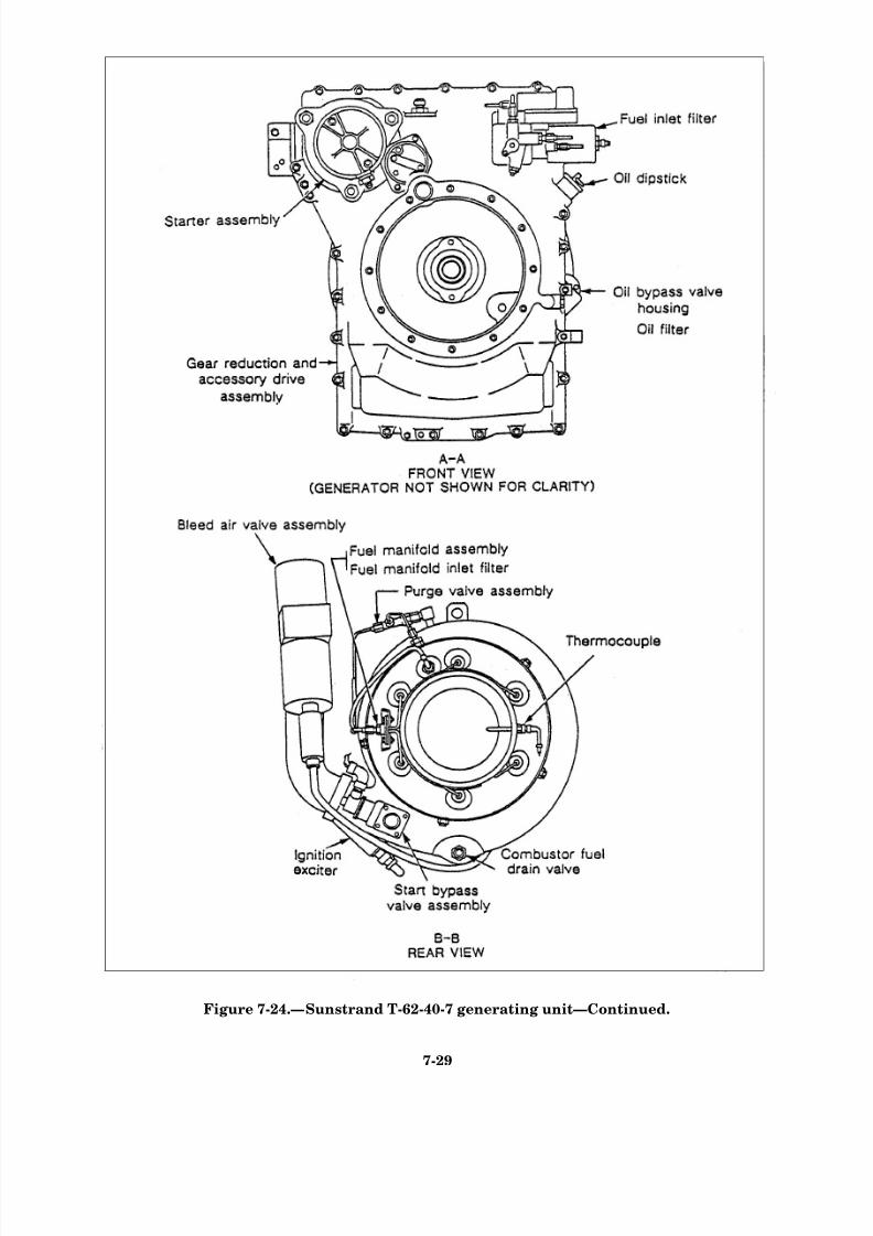
8/14/2019 US Navy Course NAVEDTRA 14115 - Gas Turbine Systems Technician Mechanical) 2
http://slidepdf.com/reader/full/us-navy-course-navedtra-14115-gas-turbine-systems-technician-mechanical 239/349
Figure 7-24.—Sunstrand T-62-40-7 generating unit—Continued.
7-29

8/14/2019 US Navy Course NAVEDTRA 14115 - Gas Turbine Systems Technician Mechanical) 2
http://slidepdf.com/reader/full/us-navy-course-navedtra-14115-gas-turbine-systems-technician-mechanical 240/349
compressor wheel and secure it to the rotor shaft flange.
The turbine wheel is pressed onto the aft end of the rotor
shaft and aligned by three dowels. A threaded bolt
fastens the turbine wheel to an internally threaded plug
in the aft end of the rotor shaft.
A circular, compressor-to-turbine air seal separates
the compressor section from the turbine section. The
seal is radially positioned on the nozzle assembly. The
axial position of the seal on the rotor shaft is maintainedby compressor pressure, which forces the seal against a
shoulder on the turbine nozzle. The cantilevered
arrangement of the rotor assembly in the air inlet
housing places both the forward and aft bearings in areas
of minimal temperature. Cooling and lubrication of the
rotor shaft bearings are accomplished by a air-oil mist
from the reduction gear and accessory drive housing,
through the output pinion (within the rotor shaft),
through the aft and forward bearings, and back into the
gear reduction and accessory drive housing.
COMBUSTOR ASSEMBLY.– The combustor is
an annular air atomizing-type. It encases the combustorliner assembly. The combustor liner is secured in the
combustor housing by four locating bolts. An external
flange at the forward end of the combustor housing
mates with an external flange on the aft end of the
turbine assembly. The combustor is secured to the
assembly by a quick-release, V-type clamp (marmon)
that fits over the flanges. The outer wall of the
combustor liner fits snugly under the outer aft edge of
the turbine nozzle assembly. The mating of the
combustor housing inner wall with the aft end of the
turbine nozzle assembly forms a circular exhaust duct
for the flow of the exhaust gases as they leave the turbineportion of the rotor assembly and flow out of the APU.
(See fig. 7-24.)
Airflow.– Intake air passes through the vanes of the
diffuser, flows between the walls of the combustor
housing and liner, and reverses direction to enter the
burner section of the combustor. This flow of air cools
the combustor housing and liner. Air is also directed
between the inner walls of the combustor housing and
liner; then it flows to the aft surface of the turbine nozzle
assembly. Additional cooling of the turbine nozzle is
accomplished by a flow of cooling air that is forced
around the aft, internal edge of the diffuser, through
equally spaced holes in the ring on the combustor inner
liner assembly, and over the aft side of the forward plate
of the nozzle assembly.
Fuel Delivery and Combustion Process.– An
igniter plug, which is mounted in a boss at the aft, left
side of the combustor housing, ignites the fuel-air
mixture by the start fuel nozzle during a start. Fuel to
the combustor is supplied through an external fuel
manifold assembly. The outlet tips of the fuel manifold
assembly are equally spaced around the combustor
housing. The tips are swagged to form an orifice at their
ends. The fuel manifold assembly provides six jets of
fuel into the throats of six small venturis, which atomize
the fuel at the aft end of the combustor liner. A combustor
drain port in the lowest point of the combustor housing
provides a drain for the fuel that might accumulate inthe combustor during a false start or other malfunction.
Thermocouple.– A dual-element thermocouple is
mounted in a boss at the aft, right side of the combustor
housing. The function of the thermocouple is to sense
exhaust temperatures. The two elements of the
thermocouple are mounted on bosses at the aft, right side
of the combustor housing. One element functions as an
overtemperature detector. The other element functions
in conjunction with the load control valve.
DIFFUSER AND TURBINE NOZZLE ASSEM-
BLY.- The diffuser is a circular casing consisting of 36 vanes on the outer periphery and 17 vanes on the
forward face. The turbine nozzle is a brazed, matched
assembly consisting of a forward circular plate and an
aft circular plate. The diffuser is secured in the aft
position of the air inlet housing by six threaded nozzle
retaining pins. These pins pass through the diffuser and
also secure the turbine nozzle assembly concentric with
the rotor assembly. The turbine nozzle assembly seats
against a mating of the diffuser at the fore and aft ends
only (not radially).
GEAR REDUCTION AND ACCESSORYDRIVE ASSEMBLY.– The gear reduction and
accessory drive assembly reduces the output rotational
speed (61,091 rpm) of the rotor assembly to the speeds
necessary to drive the APU generator and accessories.
The two-piece reduction drive housing is machined
from aluminum sand castings.
Input Pinion Assembly.– The reduction drive input
pinion drives three planetary gears that drive an
internally splined ring gear. The ring gear is centrally
splined to a short output shaft.
Output Shaft Assembly.– The external gear of the
output shaft drives the oil pump drive gear. The internal
splines of the output shaft provide for connecting the
driven equipment to the engine. The aft end of the output
shaft is supported by a ball bearing in the bearing carrier
of the planetary gear system. The middle of the output shaft
is supported by a ball bearing mounted in the forward,
internal support web of the reduction drive housing.
7-30
8/14/2019 US Navy Course NAVEDTRA 14115 - Gas Turbine Systems Technician Mechanical) 2
http://slidepdf.com/reader/full/us-navy-course-navedtra-14115-gas-turbine-systems-technician-mechanical 241/349
Planetary Gear Shafts.– The forward and aft ends
of the planetary gear shafts are supported by ball
bearings. Within the bearing carrier housing, there is a
circular bearing carrier. The circular bearing carrier is
fitted and bolted in the aft face of the drive housing,
which holds the six planetary gears’ ball bearings in
position inside the ring gear.
Intermediate Accessory Drive Assembly.– The
intermediate accessory drive gear is mounted on the gear
support shaft in the forward, upper end of the reduction
drive housing. The gear shaft is supported by a
double-row ball bearing.
The accessory drive is the upper portion of the
reduction drive assembly. The output shaft transmits
power through the intermediate gear to the fuel pump
drive and starter gears, which convert the reduction
output speed to 6,000 rpm. This is the speed required to
drive the APU’s accessories.
Fuel Pump and Starter Gears.– The fuel pump
gear operates at 4,200 rpm. When the starter is
disengaged, the starter gear is free to rotate with the
intermediate gear. When the starter is engaged, the
starter gear drives the accessory drive gear train to
supply starting torque to the GTE.
These gears are mounted on shafts supported by ball
bearings within the accessory drive portion of the
reduction drive housing. The gears and bearings are
lubricated by an air-oil mist from the reduction drive
assembly. To prevent leakage of the air-oil mist, seals
are mounted in the reduction drive housing at the ends
of the output shaft, fuel pump drive, and starter gears.
The fuel pump and engine acceleration control, whichis mounted in tandem with the fuel pump, is mounted on
the left forward pad of the reduction drive assembly. The
starter assembly is mounted on the right forward pad.
SYSTEMS
In the next sections, we will look at the following
operating systems of the Sunstrand T-62:
. Fuel system
lLubricating oil system
l Air system
. Electrical system
In the following paragraphs, we will provide a brief
description of each of these systems. For additional
information, we recommend you consult the appropriate
technical manuals.
Fuel System
The Sunstrand’s fuel system, shown in figures 7-24
and 7-25, automatically provides proper engine
acceleration and maintains a nearly constant operating
speed under all operating conditions. Fuel is supplied to
the GTE at 5 to 40 psig with a minimum flow capacity
of 200 pounds per hour.
The Sunstrand’s fuel system consists of thefollowing main components:
l
l
l
l
l
l
l
Inlet fuel filter
Fuel pump
Start, main, and maximum fuel solenoid valves
Start fuel nozzle
Purge valve
Manifold assembly
Acceleration control assembly
Let’s take a brief look at each of these areas.
INLET FUEL FILTER.– The inlet fuel filter
assembly is threaded into the fuel pump inlet port and
contains a fitting for the connection of an external fuel
supply line. The filter assembly contains a 25-micron,
disposable element.
FUEL PUMP.– The fuel pump is a positive-
displacement, gear-type pump. The pump is mounted on
the left forward pad of the accessory drive portion of the
reduction drive assembly. A 25-micron, cleanable filterelement is installed in the pump housing. The fuel pump
splined shaft fits into an eight-point square drive in the
shaft portion of the accessory drive gear. The other end
of the fuel pump driveshaft is spline-coupled to the
drivehead assembly in the engine acceleration control.
A drain port in the pump housing drains fuel that might
leak past the pump drive seal or past the drop regulating
valve pin. At 4,200 rpm, the pump is capable of
delivering 400 pounds per hour of fuel against a
discharge pressure of 400 psig.
START, MAIN, AND MAXIMUM FUELSOLE-NOID VALVES.– The start, main, and maximum fuel
solenoid valves are hermetically sealed. They are
installed on the fuel valve mounting bracket. They are
operated by an electrical input of 14 to 28 volts dc.
Stainless-steel tubing connects each valve with the
engine acceleration control assembly. The fuel solenoid
valves are controlled by the ESU.
7-31
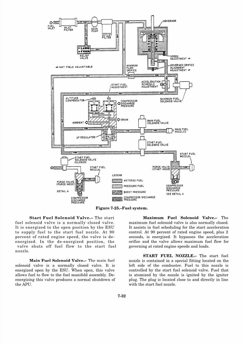
8/14/2019 US Navy Course NAVEDTRA 14115 - Gas Turbine Systems Technician Mechanical) 2
http://slidepdf.com/reader/full/us-navy-course-navedtra-14115-gas-turbine-systems-technician-mechanical 242/349
Figure 7-25.–Fuel system.
Start Fuel Solenoid Valve.– The start
fuel solenoid valve is a normally closed valve.It is energized to the open position by the ESU
to supply fuel to the start fuel nozzle. At 90percent of rated engine speed, the valve is de-
energized. In the de-energized position, the valve shuts off fuel flow to the start fuelnozzle.
Main Fuel Solenoid Valve.– The main fuel
solenoid valve is a normally closed valve. It is
energized open by the ESU. When open, this valveallows fuel to flow to the fuel manifold assembly. De-energizing this valve produces a normal shutdown of
the APU.
Maximum Fuel Solenoid Valve.– The
maximum fuel solenoid valve is also normally closed.It assists in fuel scheduling for the start accelerationcontrol. At 90 percent of rated engine speed, plus 2
seconds, is energized. It bypasses the acceleration
orifice and the valve allows maximum fuel flow forgoverning at rated engine speeds and loads.
START FUEL NOZZLE.– The start fuel
nozzle is contained in a special fitting located on the
left side of the combuster. Fuel to this nozzle iscontrolled by the start fuel solenoid valve. Fuel that
is atomized by the nozzle is ignited by the igniterplug. The plug is located close to and directly in linewith the start fuel nozzle.
7-32

8/14/2019 US Navy Course NAVEDTRA 14115 - Gas Turbine Systems Technician Mechanical) 2
http://slidepdf.com/reader/full/us-navy-course-navedtra-14115-gas-turbine-systems-technician-mechanical 243/349
PURGE VALVE ASSEMBLY.– A start fuel nozzle
purge system is used to prevent the buildup of varnish
resulting from fuel evaporation. The purge system
consists of a purge valve assembly and rigid tubing
connected to the start fuel nozzle. The purge valve
assembly is threaded into a special fitting that is installed
on the compressor discharge pressure port.
During an APU start, the start fuel solenoid valve
opens and fuel pressure forces the piston in the purge valve to one side in the valve chamber. This allows fuel
to flow through the start fuel nozzle. At approximately
65 percent of engine speed, the start fuel solenoid valve
closes to cut off fuel pressure. A return spring transfers
the piston in the purge valve to the purge position. In the
purge position, compressor discharge air flows through
the start fuel nozzle to clear the nozzle of residual fuel.
The residual fuel is directed to the combustor to be
burned.
FUEL MANIFOLD ASSEMBLY.– The fuel
manifold assembly consists of a brazed assembly of sixstainless-steel lines, each terminated with a 0.016-inch
orifice at the exit end. The main fuel transfer line is
connected between the main fuel solenoid valve outlet
and the distribution boss on the fuel manifold.
The fuel manifold filter assembly contains a
wire-cloth element. The filter is internally installed in
the housing at the inlet end of the fuel manifold assembly
and held in place by a retaining ring. The filter provides
a 10-micron, in-line filtration of the fuel before it enters
the combuster.
ACCELERATION CONTROL ASSEMBLY.–The engine acceleration control assembly consists of
three components secured together: (1) the governor,
(2) the fuel control, and (3) the bellows cover assembly.
Governor.– The governor includes a pressure relief
valve, a governor control spring, a flyweight assembly
mounted in a drivehead assembly, and a matched ball
bearing set, which supports the internally splined shaft
end of the drivehead assembly. The flyweight assembly
is located between the bearing and valve assembly and
the governor drivehead assembly. It is pivot-mounted
against the governor drivehead assembly and the
bearing plate of the bearing and valve assembly.
The threaded ports in the governor provide
attaching points for the fuel line to the main fuel solenoid
valve and the relief valve. The governor also includes a
ported differential pressure regulating valve, which
maintains a differential pressure across the fuel metering
valve ports proportional to compressor discharge
pressure and controls fuel flow to the APU.
Fuel Control.– The fuel control, which is secured to
the forward face of the governor, contains a minimum
fuel flow orifice, an acceleration needle adjustment, a
ported fuel metering valve assembly, a governor
adjusting plunger, a governor tension lever, a bearing
and valve assembly, and an outlet port. The aft end of
the fuel metering valve extends into the fuel control
housing. The spring retainer, which fits over the end of
the fuel metering valve, is held in position around the
metering valve by flanges on the spring retainer and the
bearing and valve assembly. The piston of the bearing
and the valve assembly fits into the center of the fuel
metering valve assembly.
Bellows Cover Assembly.– The bellows cover
assembly is secured to the top of the governor housing
and consists of two interconnected sections. These
sections are the diaphragm and bellows housing and a
lever housing. The diaphragm is located between the
pressure sensing portion of the bellows cover assembly
and the lever housing which, through a mechanical
connection, operates the differential pressure regulating valve in the governor housing. A diaphragm adjusting
screw is installed in the pressure sensing portion of the
bellows cover assembly.
FUEL DISTRIBUTION SYSTEM.– A single
low-pressure fuel line is necessary to supply the engine’s
fuel system from an external source (5 to 40 psig with
200 pounds per hour minimum flow). The turbine
engine’s high-pressure fuel system has stainless-steel
piping that connects the engine acceleration control
assembly with the fuel solenoid valves, compressor
pressure outlet port, purge valve, start fuel nozzle, andfuel manifold assembly. An additional stainless-steel
line supplies compressor discharge pressure to the load
control valve.
Lubricating Oil System
The lubricating oil system provides lubrication to
the high-speed input pinion, reduction and accessory
gears, shafts, and bearings. The Sunstrand’s integral
lubrication system consists of the following parts:
l Oil pump
. Oil filter and bypass relief valve
l Oil pressure relief valve (main)
. Oil pressure switch
. Oil temperature switch
l Oil distribution ring assembly
7-33
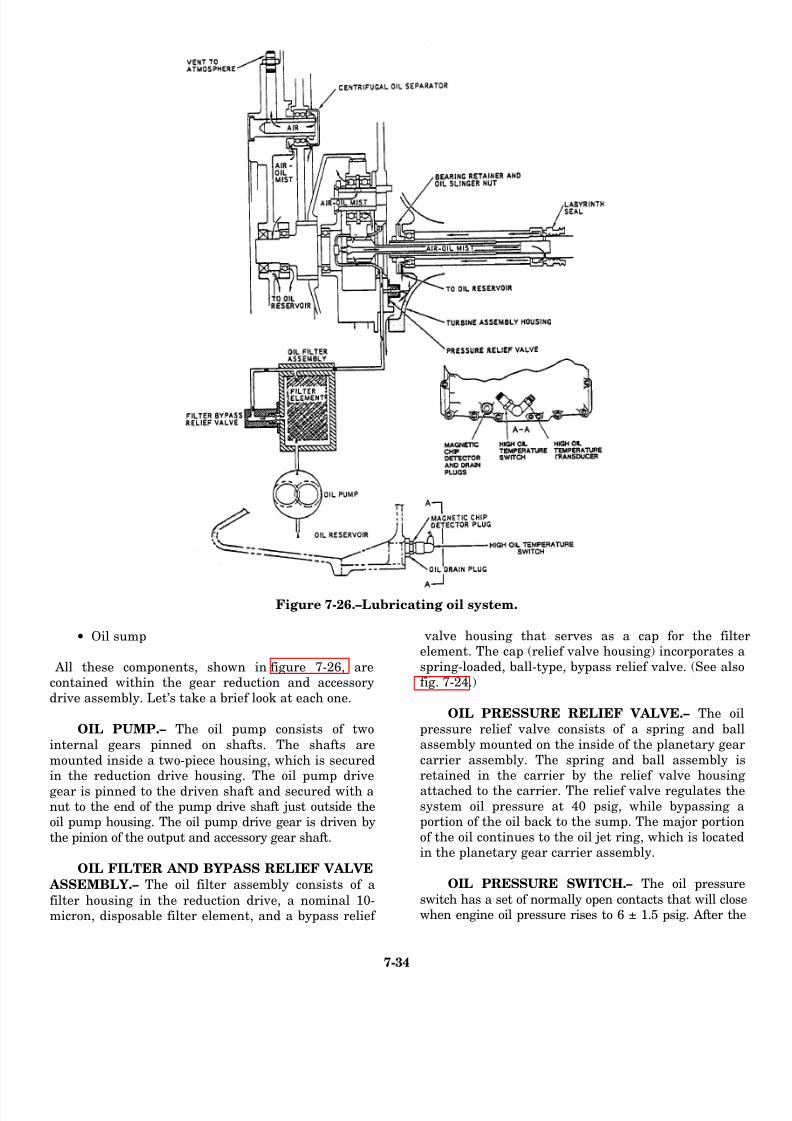
8/14/2019 US Navy Course NAVEDTRA 14115 - Gas Turbine Systems Technician Mechanical) 2
http://slidepdf.com/reader/full/us-navy-course-navedtra-14115-gas-turbine-systems-technician-mechanical 244/349
Figure 7-26.–Lubricating oil system.
• Oil sump
All these components, shown in figure 7-26, arecontained within the gear reduction and accessory
drive assembly. Let’s take a brief look at each one.
OIL PUMP.– The oil pump consists of two
internal gears pinned on shafts. The shafts are
mounted inside a two-piece housing, which is securedin the reduction drive housing. The oil pump drive
gear is pinned to the driven shaft and secured with anut to the end of the pump drive shaft just outside theoil pump housing. The oil pump drive gear is driven by
the pinion of the output and accessory gear shaft.
OIL FILTER AND BYPASS RELIEF VALVE
ASSEMBLY.– The oil filter assembly consists of a
filter housing in the reduction drive, a nominal 10-micron, disposable filter element, and a bypass relief
valve housing that serves as a cap for the filteelement. The cap (relief valve housing) incorporates a
spring-loaded, ball-type, bypass relief valve. (See alsofig. 7-24.)
OIL PRESSURE RELIEF VALVE.– The oil
pressure relief valve consists of a spring and ballassembly mounted on the inside of the planetary gear
carrier assembly. The spring and ball assembly isretained in the carrier by the relief valve housing
attached to the carrier. The relief valve regulates thesystem oil pressure at 40 psig, while bypassing aportion of the oil back to the sump. The major portion
of the oil continues to the oil jet ring, which is locatedin the planetary gear carrier assembly.
OIL PRESSURE SWITCH.– The oil pressure
switch has a set of normally open contacts that will closewhen engine oil pressure rises to 6 ± 1.5 psig. After the
7-34

8/14/2019 US Navy Course NAVEDTRA 14115 - Gas Turbine Systems Technician Mechanical) 2
http://slidepdf.com/reader/full/us-navy-course-navedtra-14115-gas-turbine-systems-technician-mechanical 245/349
Figure 7-27.–Air pressure system.
APU is operating at or above 90 percent of ratedengine speed, decreasing oil pressure below 6 ± 1.5psig opens the contacts and, through the ESU, the
APU will shut down because of low oil pressure.
OIL TEMPERATURE SWITCH.– The high
oil temperature switch is installed in the reduction
drive assembly. The switch is electrically connected tothe ESU to enable the ESU to monitor the oil
temperature and shut down the APU when the oiltemperature reaches 275° ± 5°F.
OIL DISTRIBUTION RING ASSEMBLY.–
The oil jet ring is located in the bearing carrierassembly for the planetary gear system. The jet ring
encircles the high-speed input pinion that providesthe three jets of oil that are directed at the meshpoints of the input pinion and the planetary gears.
OIL SUMP.– The oil sump is integrally cast
with the reduction gear housing. The oil sump has a
full capacity of 5 U.S. quarts. This represents the oil
requirement for (approximately) a 1-minutedeaeration period to minimize oil foaming. An oil
shield is cast integrally with the reduction drivehousing between the gears of the reduction driveassembly and the oil sump. The shield prevents the
lubricating oil in the sump from coming into contactwith the moving gears. It also prevents foaming of
the oil.
An expansion-type dipstick mounted in thereduction drive housing indicates the oil level in thesump. The dipstick is retained in place by an integral
rubber seal, which expands against the dipstick
receptacle when the dipstick folding ring is rotatedclockwise. The dipstick is integral with the oil filler
cap.
Air Pressure System
The air pressure system, shown in figure 7-27,
controls the flow of fuel during the starting phase, as afunction of engine speed. This is accomplished as the
7-35

8/14/2019 US Navy Course NAVEDTRA 14115 - Gas Turbine Systems Technician Mechanical) 2
http://slidepdf.com/reader/full/us-navy-course-navedtra-14115-gas-turbine-systems-technician-mechanical 246/349
Figure 7-28.–Sunstrand electrical system.
fuel control assembly senses the compressor
discharge pressure tapped from the air inlet housing.
START AIR OPERATION.– For starting, the
air is drawn in by the compressor wheel. Thecompressed air is tapped from the compressor
chamber through a special fitting located on top theaft center of the turbine assembly. From this point,the discharge air is transmitted to the engine
acceleration control assembly. The accelerationcontrol senses this pressure and reacts to meter thefuel to the main fuel nozzles on the fuel manifold
during the starting operation.
PURGE VALVE ASSEMBLY.– The air fromthe special compressor pressure fitting is also routedto the purge valve assembly. (The purge valve isconnected to the special compressor pressure fitting.)
During the start cycle, fuel pressure to the start fuelnozzle is greater than the compressor pressure
impinging on the purge valve; therefore, only startfuel can flow through the purge valve to the start fuelnozzle at this time. When fuel flow to the start fuel
nozzle ceases, the purge valve opens to allow
compressor discharge air pressure to flow throughthe purge valve to purge the start fuel nozzle of allresidual fuel.
LOAD CONTROL VALVE ASSEMBLY.– Com-
pressor discharge pressure is also tapped from anoutlet port on the aft bottom of the turbine housing
through tubing and a 20-micron, in-line, disposablefilter. This air pressure is used for operation of thebutterfly valve piston and the electropneumatic
torque motor in the load control valve.
The operation of the bleed air system, which
consists of the start bypass valve and bleed air valve,will be described under the electrical system.
Electrical System
Some of the components we have already described forthe other systems are also part of the Sunstrand’s electrical
system. We will now indicate how these componentsfunction as an integral part of the Sunstrand
7-36

8/14/2019 US Navy Course NAVEDTRA 14115 - Gas Turbine Systems Technician Mechanical) 2
http://slidepdf.com/reader/full/us-navy-course-navedtra-14115-gas-turbine-systems-technician-mechanical 247/349
Figure 7-29.—Sunstrand electrical harness assembly.
APU. (Refer to fig. 7-24.) Our discussions willbasically include the following engine-mountedcomponents:
• Generator
• Starter assembly
• Start bypass valve
• Start counter
• Ignition exciter
• Ignition cable
• Igniter plug
• Thermocouples
• Magnetic pickup
• Time totalizing meter (hour meter)
• Electropneumatic air bleed valve
• Oil pressure switch
• Fuel solenoid valves
As we indicated, you have already read about some of
these components. For example, the oil pressureswitch and the fuel solenoid were described in the
fuel and lubricating oil sections. You have alreadyread about the generator and the start air operation.In the following paragraphs, we will confine our
discussions to the other engine-mounted components
of the Sunstrand’s electrical system.
For the electrically operated components on theSunstrand’s GTE power unit to function properly,
electric power at 12 to 30 V dc is required during theengine start sequence. Keep this requirement in mind
and refer to figures 7-28 and 7-29 as you read aboutthe following components.
7-37

8/14/2019 US Navy Course NAVEDTRA 14115 - Gas Turbine Systems Technician Mechanical) 2
http://slidepdf.com/reader/full/us-navy-course-navedtra-14115-gas-turbine-systems-technician-mechanical 248/349
STARTER ASSEMBLY.– The starter assembly is
mounted on the forward, upper, right pad of the gear
reduction and accessory drive assembly. It is a 24-volt
dc disengaging-type starter, with an integral solenoid
and contactor assembly that is totally enclosed. The
enclosure protects this unit from exposure to dirt and
foreign material. (See figs. 7-24 and 7-27.)
The solenoid, mounted on the motor field frame,
operates the lever mechanism to shift the splined drive
into mesh with the mating splint of the starter gear inthe gear reduction and accessory drive assembly.
START BYPASS VALVE.– The start bypass valve
is a spring-loaded, normally closed, solenoid valve. The
valve is installed on the lower portion of the combustor
air manifold. A minimum of 2 to 4 psig compressor air
is sufficient to start to open the valve. (A minimum of 7
to 9 psig will fully open the valve.)
During the start cycle, the start bypass valve is open
to prevent a surge condition. When the APU reaches 90
percent of rated engine speed, plus 2 seconds, the start
bypass valve is energized to the closed position throughoutput current from the ESU upon actuation of the bleed
air valve.
START COUNTER.– The miniature start counter
is installed on the fuel valve and the electrical equip-
ment mounting bracket. This assembly is located on
the upper left side of the reduction drive. The start
counter records the total APU starts and operates on
12 to 30 volts dc.
IGNITION EXCITER.– The ignition exciter is
bolted to the turbine assembly housing. This capacitor
discharge-type exciter converts a dc input to a
high-energy ac output. The high-energy ac output is
supplied to the igniter plug for fuel ignition. The
minimum igniter rate is four sparks per second at 12
volts dc input. (See fig. 7-24.)
IGNITION CABLE.– The ignition cable connects
the ignition exciter to the igniter plug. The high-energy
pulse from the exciter to the plug is supplied through the
ignition cable. The cable is protected by a flexible metal
shielding.
IGNITER PLUG.– The igniter plug is a
10-millimeter, surface-discharge type. It is threaded into
a boss in the upper left aft section of the combustor. As
we mentioned earlier, the igniter plug provides the spark
necessary for initial ignition of the fuel during the
starting phase of the APU. (See fig. 7-24.)
THERMOCOUPLE.– A dual-element, chromel/
alumel thermocouple extends into the exhaust stream
and senses engine exhaust temperature. The output
signal of each element is transmitted to the ESU.
Overtemperature from the thermocouple to the ESU will
result in either an APU shutdown or operation of the
bleed air valve to limit bleed air flow. (See fig. 7-24.)
MAGNETIC PICKUP.– The magnetic pickup is
installed in the top center section of the reduction drive
housing assembly. The magnetic pickup generates a
voltage output as the ring gear passes through the
magnetic field surrounding the pole piece at the sensingend of the pickup. The voltage output is then transmitted
to the ESU. An overspeed/underspeed signal from the
ESU will result in an APU shutdown. (See fig. 7-24.)
TIME TOTALIZING METER.– The time
totalizing meter (hour meter) indicates the total
accumulated hours of APU operation. This unit is
installed in the fuel valve and the electrical equipment
mounting bracket, located on the upper left side of the
reduction drive. The time totalizing meter operates on
12 to 30 volts dc.
ELECTROPNEUMATIC AIR BLEED
VALVE.– The electropneumatic servo actuated air
bleed valve (load control valve) consists of a piston
operated butterfly flapper and an electropneumatic
torque motor. Operating air pressure for the butterfly
piston is obtained from compressor discharge air
pressure through a port in the valve body. (See fig.
7-24.) The air pressure (filtered) is controlled by the
electropneumatic torque motor, which regulates the
pneumatic pressure to the piston in the air bleed valve,
thereby positioning the butterfly flapper. This
operation is performed as a function of an electrical
signal produced by the ESU. Thus, any changes in
exhaust temperature will result in movement of the
butterfly flapper to control the bleed air flow from the
APU, maintaining exhaust gas temperatures within
safe operating limits.
We have just discussed the major design and
operating systems of the Sunstrand APU found on the
LCAC-class ships. In the following sections let’s shift
our focus to the FFG-7 class ship and the Detroit Diesel
16V149, which furnishes its electric power.
DETROIT DIESEL 16V149If assigned aboard an FFG-7 class ship, you, the
GSM, will need to be familiar with the Detroit Diesel
16V 149. The FFG-7 class ship’s electric power is
supplied by four ac generators, shown in figure 7-30.
Each of these generators is driven by a Detroit Diesel
16V149. These units are also capable of providing
7-38

8/14/2019 US Navy Course NAVEDTRA 14115 - Gas Turbine Systems Technician Mechanical) 2
http://slidepdf.com/reader/full/us-navy-course-navedtra-14115-gas-turbine-systems-technician-mechanical 249/349
Figure 7-30.—Detroit Diesel 16V149 (SSDG on FFG-7 class ships) (left and right side view).
take-home power in the event of a casualty to the
propulsion system. Two of the units are equippedwith start air compressors, which we will describelater in this chapter.
DESIGN AND OPERATION
Each SSDG set is driven by a 1,600
horsepower, V-type, 16-cylinder, two-cycle,turbocharged, intercooled Detroit Diesel engine with
right-hand rotation. The engine has a total
displacement of 2,389 cubic inches and acompression ratio of 16:1. Normal operating speedis 1,800 rpm.
The engine has individual cylinder heads,crosshead-type pistons, unit fuel injection, and a full
scavenging air system. Figure 7-30 shows the designand location of the key components of the DetroitDiesel 16V149.
7-39

8/14/2019 US Navy Course NAVEDTRA 14115 - Gas Turbine Systems Technician Mechanical) 2
http://slidepdf.com/reader/full/us-navy-course-navedtra-14115-gas-turbine-systems-technician-mechanical 250/349
SYSTEMS
Refer to figure 7-30 as we talk about the following
five major systems of the Detroit Diesel 16V149:
l
l
l
l
l
Fuel system
Lubricating oil system
Jacket water cooling system
Starting air system
Air intake and exhaust system
We will take just a brief look at each of these systems.
For a more in-depth view, we recommend you consult
the appropriate technical manuals.
Fuel System
The diesel’s fuel system consists of the following
components:
l
l
l
l
l
l
Fuel strainer (primary)
Fuel pump
Fuel filter (secondary)
Fuel block and check valves
Fuel manifolds
Fuel injectors
The components that are external to the engine
include the fuel service tank, fuel return cooler, and
connecting lines.
OPERATION.– During operation, the fuel is drawnfrom the service tank through the (primary) strainer
by the engine-mounted fuel pump. The pump passes
the fuel to the secondary filter to the junction block.
At the junction block, the fuel is routed to the fuel inlet
manifolds for each cylinder bank. The injectors
receive fuel from the inlet manifold through
individual pipes. A small portion of the fuel supplied
to the injector is pumped into the cylinder through the
spray tip at high pressure. Surplus fuel passes through
the injector, serving to lubricate and cool the working
parts. It then returns from the outlet side of the
injector, through the fuel outlet pipes, to the returnmanifold. The return fuel the passes through the fuel
junction block, to the cooler, and returns to the engine
fuel inlet.
CONTROL AND MONITORING COMPO-
NENTS.– The control and monitoring components in
the auxiliary fuel service system consist of the
solenoid-operated tank suction valves and the
quick-closing shut-off valves located in the supply line
from each tank.
Solenoid-Operated Tank Suction Valves.–The
solenoid valves can be opened and closed locally or
from the EPCC. They are provided with a manual
override in case of coil failure or loss of power.
Quick-Closing Shut-Off Valves.– The quick-
closing shut-off valves are operated from the space entryaccess trunks.
Resistance Temperature Deteetor and Ther-
mometer Assemblies.– A resistance temperature
detector (RTD) and a thermometer are located in the
discharge line from the fuel cooler. The RTD provides a
signal to the EPCC for a demand display readout, and
actuates audible and visual alarms when fuel
temperature exceeds 115°F. The thermometer is
provided for local monitoring.
Pressure Transducers.– Two pressure transducers
on each engine provide a demand display readout anda continuous display of the engine fuel pump
discharge pressure. The pressure transducers also
provide low fuel pressure audible and visual alarms at
the EPCC downstream of the fuel filter. The alarm is
set at 35 psig.
Pressure Switches.– Three pressure switches in the
fuel system area part of the automatic control circuit. A
tank level instrument in each fuel tank provides
continuous tank level, demand display readout, and
high- and low-level alarms at the EPCC.
STRAINER ASSEMBLY.– The fuel strainer is a
metal-edge disk-type simplex unit with dual strainer
elements. The strainer consists of a strainer element
surrounded by a sump to collect foreign material
removed from the fuel stream. The element consists
of a series (stack) of thin edge-type disks separated
slightly by spacer disks. The strainer element is
arranged on a spindle and clamped together by long
screws or studs. A handle attached to the spindle is
used to rotate the strainer element against the cleaner
or scraper blade.
The fuel that enters the strainer is forced between
the casing and the disk assembly and then passesthrough the disks to the center of the element. The fuel
then passes up through the element and out through the
strainer outlet.
FUEL PUMP ASSEMBLY.– The fuel pump is a
positive-displacement gear-type pump. It is used to
7-40

8/14/2019 US Navy Course NAVEDTRA 14115 - Gas Turbine Systems Technician Mechanical) 2
http://slidepdf.com/reader/full/us-navy-course-navedtra-14115-gas-turbine-systems-technician-mechanical 251/349
transfer fuel from the service tank to the fuel injectors.
The pump circulates an excess fuel supply through the
injectors. The excess fuel purges air from the system and
cools the injectors. The used fuel is returned to the
engine fuel inlet through the cooler.
The fuel pump is mounted on an adapter attached to
the flywheel housing and is driven off the end of the
blower drive gear by a coupling fork. The fuel pump is
a right-hand rotation pump. The fuel pump pressure is
regulated by a spring-loaded relief valve that is
incorporated into the pump casing. The relief valve is
set to lift at 100 psig in the event of high pump discharge
pressure. The excess fuel recirculates from the pump
discharge to the suction side of the pump.
FILTER ASSEMBLY.– The fuel filter assembly
consists of four housing units in a duplex arrangement.
A selector handle is used to shift from the active
elements to the standby units. Each filter unit consists
of a shell, a cover, and five replaceable filtering
elements. The filter elements slide over a filter guide.
The fuel enters the shell and passes inward through the
filter element, where it enters the filter guide and passesto the filter outlet. Check valves are installed in the filter
outlet connections to prevent fuel backflow to the
standby unit. The filter elements should be replaced
when the differential pressure exceeds 15 psid.
FUEL BLOCK AND CHECK VALVE
SYSTEM.– The fuel junction block distributes fuel
from the filter to the fuel manifolds through flexible
lines. A valve, located in the inlet piping before the fuel
junction block, prevents fuel stoppage through the
injector, which could cause cylinder head damage. A
check valve, installed in the fuel junction block on theoutlet (spill) side, prevents fuel from draining from a
high mounted fuel tank back into the injectors when the
engine is not running. An orifice (0.136 inch and 0.1695
inch) drilled in the fuel pressure relief valve plug
maintains pressure in the fuel system.
FUEL MANIFOLDS.– The fuel manifolds are
attached to the top of the cylinder block on each bank of
the engine. Fuel connectors, installed in the bottom of
the manifold, supply fuel to the injector and return
excess fuel from the injector back to the return passage
in the manifold. The manifolds are installed with the
supply passages on the outboard side on each injectorbank. Surplus fuel is returned to the fuel strainer inlet
through the return fuel cooler.
UNIT INJECTOR ASSEMBLIES.– Combustion
required for satisfactory engine operation depends on
the injection of a small quantity of accurately metered
and finely atomized fuel into the cylinder at the correct
time. Unit injectors combine the high pressure pump
necessary for proper injection and the injection nozzle
in one unit. The injectors create the high fuel pressure
required for efficient injection. They both meter and
inject the correct amount of fuel required by the engine
load, and atomize the fuel for mixing with the air in the
combustion chamber.
The injector fits snugly in the injector tube
installed in the cylinder head. The tip projects slightlybelow the bottom of the cylinder head. Jacket water
circulates around the lower part of the injector tube to
keep it cool.
Each injector has two connections, one to supply
fuel and the other to carry away bypassed fuel (spill).
The injector is actuated by the injector rocker, which
works directly off the camshaft. The amount of fuel
injected is regulated by the control rack which is
operated by a lever secured to the rack control tube. The
control tube is positioned by linkages from the governor
actuator.
COOLER.– The return fuel cooler is of the shell and
tube design. The cooler is a single-pass heat exchanger.
The heads are bolted to the shell assembly. Baffles are
used along the length of the tube bundle to support the
tubes and to direct the flow of fuel. Seawater is used as
the coding medium.
Now that we have looked at the Detroit Diesel’s fuel
system, let’s examine its lubricating oil system.
Lubricating Oil System
This efficient lubricating oil system provides
lubrication for both the diesel engine and the generator
from a common system. The Detroit Diesel’s lubricating
oil system consists of the following main components:
l Oil sump
. Oil pump and relief valves
* Oil filter
l Oil cooler
. Regulating valves
. Monitoring system
Let’s look briefly at each of these components. For an
in-depth view, again, we recommend you consult the
appropriate technical manuals.
7-41
8/14/2019 US Navy Course NAVEDTRA 14115 - Gas Turbine Systems Technician Mechanical) 2
http://slidepdf.com/reader/full/us-navy-course-navedtra-14115-gas-turbine-systems-technician-mechanical 252/349
MAIN OIL SUMP.– The main oil sump is a
reinforced fabricated steel plate assembly that supports
the engine on its base assembly. The main oil sump is
equipped with a series of handholes along the sides for
access to the rod bearings, oil pump, and pressure
regulating valves. Mounted on the handhole covers are
the lube oil discharge fitting, the lube oil fill and drain
fittings, and the ribbon-type dipstick.
OIL PUMP.– The oil pump is mounted on the two
rear main bearing caps and is driven by the rearcrankshaft gear. The oil pump assembly consists of a
main section and a scavenging pump section mounted
in tandem. The scavenging oil pump is not used.
The main oil pump takes a suction from the sump
through the inlet screen and suction pipe and
discharges into the oil discharge line. When the pump
discharge pressure exceeds 100 psig, the
spring-loaded relief valves mounted on the oil
discharge fitting lift to direct the excess oil back to the
sump. The oil discharge pipe leads out of the sump
through the rear hand hole cover on the right side and
connects to the ship’s lube oil piping system througha flexible connection.
LUBE OIL FILTER AND COOLER ASSEM-
BLIES.– The lube oil filter and cooler are mounted off
the engine. Ship’s piping routes the lube oil from the
engine oil outlet to the lube oil filter, where particulate
matter is filtered out.
Filter Assembly.– The lube oil filter is a four-
element, full-flow assembly. It is equipped with a bypass
relief valve at each filter element. If one of the filter
elements should become clogged, the bypass valve for
that element will open when the differential pressurereaches 20 psid. The bypass valve will then maintain the
oil flow with only a slight reduction of filtration. Lube
oil is piped from the filter to the shell side of the oil
cooler.
Oil Cooler.– The lube oil cooler is similar in design
to the fuel return cooler. It is a single-pass, shell and tube
design heat exchanger. This oil cooler uses jacket water
as the cooling medium. After passing through the oil
cooler, the lube oil returns to the engine through a
flexible connector and the final lube oil strainer, which
is mounted on the left-hand side.
REGULATING VALVES.– The main oil gallery
extends the full length of the cylinder block and
connects with the main bearings, camshaft bearing, and
gear trains through drilled passages. Stable oil pressure
is maintained under various conditions by two
spring-loaded pressure regulating valves. These valves
are located at the ends of two of the four vertical oil
galleries. These pressure regulating valves are similar in
construction to the pressure relief valves mounted at the
main oil pump. When the oil pressure at a regulating
valve exceeds 50 psig, the valve lifts and discharges the
excess oil back to the engine oil sump.
OIL DISTRIBUTION SYSTEM.– Oil from the
main oil gallery flows through drilled passages to each
main bearing and through drilled passages in the
crankshaft to each adjacent journal bearing. A groove inthe upper half of the rod bearing directs oil to the piston
pin through a drilled passage in the connecting rod. A
portion of the oil is used to lubricate the piston pin; the
other part is sprayed on the underside of the piston dome
for cooling.
Oil from the main oil gallery is also picked up by
diagonal holes in the camshaft and directed through an
axial passage to the couplings and drive shafts located
at the rear of the camshaft. The valve and injector
operating mechanism is lubricated from both the
camshaft bearing caps and the grooves in the camshaft
bearings. The camshaft lobes and the rocker arm rollersare lubricated by spray jets machined in the bearing
caps. Excess oil from the rocker arms lubricates the
valve stems.
The gear train is lubricated by oil from passages
drilled in the cam hubs and the idler gear retaining bolts,
and from splash from the main oil sump. A certain
amount of oil also spills into the gear train compartment
from the blower drive bearing and the idler gear
bearings. The idler gear bearings are pressure lubricated
from the main oil gallery.
The lube oil manifold is mounted between theengine and the block. It supplies oil to the turbochargers
and generator bearings. Oil flows from the lube oil
manifold to the turbochargers through an external tube
and flexible hose connections.
MONITORING SYSTEM COMPONENTS.–
The lube oil monitoring system consists of a pre-start
lube oil pump, pressure gauges, transducers,
temperature sensors, pressure shutdown and alarm
switches, a low oil level switch, and an oil filter
differential pressure transducer. Except for the
pre-start lube oil pump, these lube control and
monitoring system components are automatic without
any operator control.
Pre-Start Lube Oil Pump.– The pre-start lube oil
pump is provided to ensure the lube oil system is charged
with oil while the engine is in a standby condition. This
pump permits the system to be charged after
7-42

8/14/2019 US Navy Course NAVEDTRA 14115 - Gas Turbine Systems Technician Mechanical) 2
http://slidepdf.com/reader/full/us-navy-course-navedtra-14115-gas-turbine-systems-technician-mechanical 253/349
maintenance or any extended idle periods. This unit
consists of an electric motor directly connected to a
pump. It has local start/stop controls and remote start
controls and monitoring adjacent to the EPCC.
Resistance Temperature Detectors.– RTDs are
provided at both the engine inlet (cooler outlet) and the
pump discharge. The inlet RTD provides a signal to the
EPCC to actuate an audible and visual alarm if the oil
temperature exceeds 225°F. The signal also allowsdemand display or data logger printout. The pump
discharge RTD provides a continuous display at the
EPCC.
Pressure Transucers.– Pressure transducers are
located at the engine inlet, the oil manifold, and the
pump discharge. The manifold transducer provides
continuous display and actuates an audible and visual
alarm at the EPCC when the oil pressure drops to 48
psig. The discharge transducer gives a demand display
only. The engine inlet transducer provides a gauge
readout on the local control panel.
Level and Pressure Switches.– A level switch
mounted in the oil sump provides an audible and visual
alarm when the sump level drops 9.5 inches below the
full mark.
Two pressure switches are provided on the system.
One switch actuates an audible and visual alarm. The
other switch automatically shuts the engine down when
oil pressure drops below 42 psig.
Ventilation System.– The crankcase ventilation
system removes harmful vapors from the crankcase,gear train, and valve compartments. The crankcase is
vented through four breather assemblies. These
assemblies are mounted on the rocker covers to an
electrostatic vent fog precipitator. The breather
assemblies are connected to the precipitator by four
rubber hoses.
The precipitator is a two-stage device that removes
oil fog and particulate matter from the airstream flowing
from the breather vents. It is designed for continuous
operation in a maximum ambient air temperature of
225°F and a maximum flow rate of 150 cubic feet per
minute (cfm). It is most efficient in the 50 to 100 cfm
range.
Now that you have taken a look at the components
of the lube oil system, let’s look at the Detroit Diesel’s
cooling system.
Jacket Water Cooling System
The jacket water cooling system uses fresh water,
circulated by a centrifugal pump, to keep the engine
cool. The jacket water system also cools the lube oil and
gives up heat to the waste heat system.
COMPONENTS.– The Detroit Diesel’s jacket
water cooling system contains both engine-mounted and
off-engine components. Let’s take a look at these
components and how they work together.Engine-Mounted Components.– The engine-
mounted components include the following units:
l Water pump and inlet adapter
. Water inlet and outlet manifolds
. Jacket water outlet
These components are mounted on or to the engine
itself.
Off-Engine Components.– The off-engine
components include the following units:
l
l
l
l
l
l
These
A 30-gallon jacket water expansion tank
A 5-gallon water treatment tank
Cooler
Waste heat exchanger
Temperature regulating valve
Lube oil cooler
components are mounted off the engine and are
located in the ship’s piping system.OPERATION.– The water pump is mounted on the
engine front cover and is driven by the front
crankshaft gear through two idler gears. It draws a
suction from the off-engine system and pumps water
into the cylinder block, around the cylinder liners, and
through the cylinder heads, to the water outlet
manifolds. The flow divides in the water outlet
manifolds with approximately 60 gallons per minute,
discharging to the exhaust manifolds at 30 gallons per
minute per side.
A flow of approximately 400 gallons per minutedischarges into the jacket water outlet. From the jacket
water outlet, the water then returns to the off-engine
system for cooling.
Monitoring, Control, and Regulating
Components.– Two RTDs are provided in the jacket
water outlet line. One RTD sends a signal to the EPCC
7-43

8/14/2019 US Navy Course NAVEDTRA 14115 - Gas Turbine Systems Technician Mechanical) 2
http://slidepdf.com/reader/full/us-navy-course-navedtra-14115-gas-turbine-systems-technician-mechanical 254/349
for a continuous display and to actuate a high
temperature audible and visual alarm. The alarm is set
at 205°F. The second RTD supplies a signal to an
indicator mounted on the LOP.
A differential pressure switch is located between the
inlet and outlet of the engine. This switch sends an alarm
signal to the EPCC, which will shut down the engine
upon a loss of jacket water flow.
Water from the exhaust manifolds enters cored
passages in the engine front cover and returns to thepump suction. After leaving the engine, the flow of
jacket water is diverted between the jacket water cooler
and the waste heat exchanger. (A three-way temperature
regulating valve in the piping system is used to control
the division of the flow.) The jacket water recombines
after passing through one or both heat exchangers, flows
through the lube oil cooler, and back to the water pump
suction flange.
The three-way temperature regulating valve and
auxiliaries form a control circuit that diverts the jacket
water to the jacket water cooler or the waste heat
exchanger, depending on the engine jacket water and
the waste heat exchanger freshwater outlet
temperatures. The temperature regulating valve
assembly consists of a three-way diverting valve with
a reverse-acting, air-operated diaphragm actuator and
a valve positioner controlled by two temperature pilot
controllers. The pilot controllers work together to
direct all jacket water to the waste heat exchanger
when the outlet temperature of the waste heat fresh
water is < 171°F and that of the jacket water is
< 191°F. When the waste heat temperature is between
171°F and 178.5°F and the jacket water is between
191°F and 199°F, both controllers will regulate to divide
the flow between the jacket water cooler and the waste
heat exchanger. If the waste heat temperature rises
above 178.5°F or the jacket water temperature rises
above 199°F, the affected pilot will close, shutting off
control air pressure to the control valve and diverting the
jacket water to the required area.
Now that you have seen how the jacket water
cooling system works, let’s look at the air systems.
Air Systems
The Detroit Diesel’s air systems consist of
starting air system and the intake and exhaust
system.
STARTING AIR SYSTEM.– The starting
the
air
air
system supplies compressed air to the engine starter
from the high-pressure air flasks. Each flask is charged
at 3,000 psig from the ship’s high-pressure air system.
The system has sufficient capacity for 10 engine starts
before recharging is necessary.
The high-pressure air is reduced to 150 psig
through a reducing station. One start air reducing
station with associated piping is installed at each
SSDG. A pressure transducer and pressure switch are
installed in the start air piping to the engine. The
transducer provides a signal to the EPCC to actuatean audible and visual alarm whenever the air pressure
drops to 100 psig. The pressure switch actuates an
alarm at the local alarm panel outside the SSDG
enclosure.
AIR INTAKE AND EXHAUST SYSTEM.– The
air intake and exhaust system supplies air to the
cylinders for combustion and scavenging. During
operation, the air is drawn into the blower section of
the turbocharger through an air filter, where it is
compressed and the temperature is increased. It is then
delivered to the intercooler where the air temperature
is reduced. From the intercooler, the cooled dense
charge of air is routed to the blower intake. The blower
further compresses the air and sends it to the air box
that surrounds the cylinder liners. The air is then
forced into the cylinders for combustion.
After combustion takes place, the exhaust valves
open and the hot gases are discharged to the exhaust
manifold. The exhaust manifold and adapter direct the
exhaust gases to the turbine section of the turbocharger.
After providing the turbocharger with its driving
medium, the hot exhaust gases are routed to a muffler
located in the uptake space.
The turbocharger consists of a radial inward flow
turbine wheel and shaft assembly and a centrifugal
compressor wheel mounted on the opposite end of the
turbine shaft. The turbine housing is a heat-resistant
alloy casting that encloses the turbine wheel and
provides flanged exhaust gas inlet and an axial exhaust
gas outlet. The turbine housing is bolted to the center
housing. The compressor housing has an axial air inlet
and a discharge connection. It is connected to the inlet
air cleaner and to the outlet piping with a clamp
arrangement. The compressor housing is clamped to the
compressor end of the center housing. The turbocharger
is mounted on the exhaust manifold adapter with
connectors.
The two intercoolcrs are mounted at the rear of the
engine at the top. They are used to cool the compressed
air from the turbochargers. They consist of an air inlet
7-44

8/14/2019 US Navy Course NAVEDTRA 14115 - Gas Turbine Systems Technician Mechanical) 2
http://slidepdf.com/reader/full/us-navy-course-navedtra-14115-gas-turbine-systems-technician-mechanical 255/349
housing, a core, a cover plate, and a seawater inlet/outlet
plate. Each intercooler is shared by two turbochargers
with an air elbow and hose attached to the air inlet
shutdown assembly with bolted flanges. The air is
cooled by circulating seawater through the core of the
intercoolers.
The air shutdown housing is mounted between the
intercoolers and serves as a plenum chamber for the
intake manifold. The air shutdown assembly is
mounted in the shutdown housing. It consists of aspring-actuated damper (valve) pivoted over the air
outlet to the intake manifold and a shutdown solenoid.
The solenoid actuates a latch mechanism to release
the valve plate when an emergency shutdown signal
is received. The emergency shutdown solenoid can be
actuated by a signal from the Halon interlock, the
engine overspeed circuitry, or the remote
EMERGENCY STOP push button at the EPCC. A
manual trip cable is also provided at the machinery
space access.
The two roots-type blowers are connected in tandem
and mounted to the air box between the cylinder banks.The two three-lobed rotors rotate in opposite directions
to provide supercharged air to the engine. The helical
designed lobes are used because fewer lobes are needed
to provide a greater airflow capacity in a smaller size
without sacrificing the smoothness of flow.
You have now read about the basic construction,
functions, and operations of the electric plants installed
on gas turbine-powered ships. In the remainder of this
chapter, you will read about some of the important safety
requirements and practices you must observe whenever
you are preparing to perform or supervise maintenance
of these plants. You will also read about some of the
more common routine maintenance procedures for these
plants. As a GSM, you will need to be aware of these
procedures and your responsibilities for performing
them correctly.
ROUTINE MAINTENANCE AND
REPAIRS
In this section, we will briefly discuss some of the
common shipboard maintenance practices and repair
procedures that you, the GSM, will be expected toperform on your ship’s electric plant. First, we will take
a look at some of the more common maintenance
responsibilities you will encounter for your ship’s GTE.
Next, we will tell you about some maintenance
responsibilities you will likely have concerning other
areas of the electric plant. Because it is so important in
today’s Navy, we will also tell you about some important
safety considerations you should keep in mind
whenever you are working with or around GTEs or your
ship’s electric plant equipment.
GAS TURBINE ENGINES
As we mentioned earlier, the Allison 501-K17 is
the most widely used GTE on board the Navy’s gas
turbine-powered ships for electric power generation.
This is why we will use the Allison 501-K17 as astandard model as we discuss the general maintenance
and repair requirements that are fairly common to
most of the GTEs. Remember, even though we may
use the Allison 501-K17 as our standard example, you
should be aware that the maintenance requirements
will be applicable to more than one type of prime
mover. Wherever necessary, we will indicate the
specific procedures that apply to a particular prime
mover. To maintain your engine in peak performance,
you will perform these routine procedures quite
frequently.
NOTE
The contents of this section are provided for
training purposes only and are not intended to
replace the authorized maintenance and repair
procedures for your ship. For the authorized
maintenance practices and specifications for
your ship, always consult the appropriate
MRCs and technical publications.
Before continuing with this section, you should take
time to refresh your memory concerning the safety
precautions you should follow whenever you plan to
perform maintenance on any GTE prime mover.
SAFETY PRECAUTIONS
Chapter 2 of this TRAMAN told you about some
of the safety precautions you should use whenever
you are handling fuels or other hazardous petroleum
products. In the following paragraphs, we will focus
on the safety precautions you should take whenever
you are performing, supervising, or preparing to
perform maintenance on any section of a GTE prime
mover.
Remember, these precautions are general. You
should always follow the authorized guidelines and
specifications for your ship. In fact, the most important
safety rule you can follow is to adhere conscientiously
7-45

8/14/2019 US Navy Course NAVEDTRA 14115 - Gas Turbine Systems Technician Mechanical) 2
http://slidepdf.com/reader/full/us-navy-course-navedtra-14115-gas-turbine-systems-technician-mechanical 256/349
to all authorized safety practices, requirements, and
procedures for your ship. As a responsible GSM, you
must comply with the guidelines and regulations
contained in the current edition of Navy Safety
Precautions for Forces Afloat, OPNAVINST 5100.19B,
and your ship’s EOSS documents.
Let’s first look at some of the safety precautions for
maintenance performed inside the engine enclosure.
Next, we will talk about safety precautions for
maintenance performed within the turbine inlet plenum.
ENGINE ENCLOSURE
As you are already aware, the base enclosure
assembly of a GTE consists of a shock-mounted base,
an enclosure, a gas turbine mounting system, intake and
exhaust systems, fire detection and extinguishing
systems, a fuel enclosure heater, a lighting system, and
a gas turbine water wash system.
The purpose of the engine enclosure is to provide athermally and acoustically insulated structure for the gas
turbine assembly as well as connections for electrical,
fire extinguishing, and air and liquid services. Because
the GTE operates inside this enclosure, its inner walls
arc designed to withstand high temperatures. Because
ventilation air is supplied to the enclosure, the
temperature of its outer walls normally will not exceed
150°F.
Among the gas turbine ship classes we have
discussed, the main design differences in the enclosure
are in the access areas to the engine. The FFG-7 class
ship has doors on either side of the enclosure. The
DD-963, DDG-993, and CG47 class ships have only
one door with a top hatch and an access ladder. On the
DDG-51 class ships, GTM access is provided by a side
door and a top hatch. Removable side panels are
provided next to the door. On the LCAC-class ships, the
enclosure is modular.
Regardless of the class of ship or the design of the
engine enclosure, you must observe the following
standard safety practices whenever you are preparing to
perform or supervise maintenance within an engine
enclosure:
1. Comply with all authorized safety regulations
and requirements for your ship, including Navy Safety
Precautions for Forces Afloat, OPNA IVIN S T 5100.19B,
and the EOSS documents for your ship.
2. Tag the gas turbine/diesel generator OUT OF
SERVICE.
3. Deactivate the fire-extinguishing system.
4. Allow the engine to cool. In the event of an
emergent y shutdown of a turbine engine when it is not
possible to cool down the engine according to the
normal shutdown procedures, you must use an
additional precaution.
CAUTION
To minimize time before personnel can
safely enter the enclosure, you may want to cool
the turbine by motoring. But do not motor for
more than 2 minutes. Also, keep in mind that it
may not be desirable or possible to motor a gas
turbine engine, depending on the reason for the
emergency shutdown.
5. Post a safety observer at the door.
6. Wear the required protective clothing.
7. Open the access doors and make sure they
remain open during all maintenance procedures.
8. Make sure the power sources are secured
because of the potentially hazardous voltages.
9. Make certain that tools, parts, materials, test
equipment, and other objects are accounted for before
personnel enter and after they exit the enclosure.
10. After the maintenance has been completed,
make certain all personnel have exited and are clear of
the enclosure before the access doors are closed.
As you are following the required safety procedures for
your ship, use your common sense. Remember, many
accidents are the result of inattentiveness.
TURBINE INLET PLENUM
In addition to the safety precautions we just
discussed for maintenance within the engine enclosure,
you must comply with the following special precautions
whenever you prepare to perform or supervise
maintenance within a turbine inlet plenum:
1. Before entering the enclosure, comply with all
the precautions we described for maintenance within the
engine enclosure.
2. Before entering the intake plenum or inlet air
duct, remove all articles from your pockets. This means
all personnel should remove all objects from clothing or
pockets, including badges, identification tags, and hats.
7-46

8/14/2019 US Navy Course NAVEDTRA 14115 - Gas Turbine Systems Technician Mechanical) 2
http://slidepdf.com/reader/full/us-navy-course-navedtra-14115-gas-turbine-systems-technician-mechanical 257/349

8/14/2019 US Navy Course NAVEDTRA 14115 - Gas Turbine Systems Technician Mechanical) 2
http://slidepdf.com/reader/full/us-navy-course-navedtra-14115-gas-turbine-systems-technician-mechanical 258/349
the wash is complete, the GTE is usually started and run
for approximately 5 minutes to dry out the engine.
TESTS AND INSPECTIONS
Many tests and inspections that are routinely
accomplished are covered by the PMS or
manufacturer’s technical manuals. As part of your
responsibilities for troubleshcmting and inspecting theGTE, you must also be knowledgeable of borescoping.
We will discuss borescoping later in this chapter.
In the following paragraphs, we will confine our
discussion to the tests and inspections you will be
required to perform for specific components and various
parts of your GTE. After we look at the individual
components, we will take a look at the GTE and your
responsibilities for borescoping.
Compressor
The compressor contains several pieces of
equipment that will require maintenance much more
frequently than the compressor itself. Most of the
internal maintenance for a compressor will be
accomplished at a naval air depot (NADEP) or shore
intermediate maintenance activity (SIMA).
Unless you are assigned to a SIMA, the only
maintenance procedure that you, the GSM, will likely
perform on the compressor is cleaning. In the following
paragraphs, let’s take a look at your responsibilities for
cleaning and maintaining the various componentsassociated with the compressor.
BLEED AIR VALVES.– On the Allison GTE, the
fifth- and tenth-stage bleed air valves are used to prevent
compressor stalls during engine start up. Your
maintenance of these valves will be basically limited to
cleaning the screens and visually inspecting the
wire-braid hoses for proper operation during starts, fire
stops, and water washing.
START AIR BYPASS VALVE.– Much like the
Allison’s fifth- and tenth-stage bleed air valves, the
Sunstrand uses the start air bypass valve to preventcompressor surge (stall) during starting. Your
maintenance for the Sunstrand’s valve will be similar to
that for the Allison’s fifth- and tenth-stage bleed air
valves. In both cases, your responsibilities will be
limited to visual inspections and checking for proper
operation during starts.
Two other valves that work hand-in-hand with the
fifth- and tenth-stage bleed air valves are the
three-way bleed air control valve and the speed
sensitive valve.
THREE-WAY BLEED AIR CONTROL
VALVE.– The three-way control valve is used to
port fourteenth-stage bleed air to the fifth- and
tenth-stage bleed air valves. The air holds these
valves closed at engine speeds above 12,780 rpm.The three-way control valve also ports ship’s
service air to hold these valves closed during an
enclosure fire stop sequence. Your maintenance of
the three-way bleed air control valve will consist
of tests and inspections through routine PMS and
in conjunction with safety checks.
SPEED SENSITIVE VALVE ASSEMBLY.– The
speed sensitive valve is the controller (brain) for the
bleed air system. It is attached to and driven by the
accessory gearbox. When engine speed is below
12,780 rpm, the valve activates to vent the bleed airreceived from the diffuser (fourteenth-stage air) to the
atmosphere, thereby allowing the engine’s internal air
pressure to push open the bleed air valves. When
engine speed exceeds 12,780 rpm, the air is ported
through a filter to the bleed air valves to hold them
closed.
Your main responsibility for this system is to keep
the filter located between the speed sensitive valve and
the bleed air valves clean. The filter is a cleanable mesh
type that is consistently exposed to salt, dirt, and
moisture. If this filter is not kept clean, the system mayend up with sufficient air pressure to hold the fifth-stage
bleed air valves closed but not enough to hold the
tenth-stage valves closed. If the filter becomes
completely blocked, both sets of valves will remain
open, creating excess air pressure in the engine
enclosure and increasing the chances of a compressor
stall.
CUSTOMER BLEED AIR VALVE.– Although it
is installed in the Allison, Garrett, and Sunstrand
systems, the customer bleed air valve serves a different
function on each GTE.
Allison.– The Allison’s bleed air valve is installed in
the enclosure on the base. It provides bleed air to the
entire bleed air system. This air is used for SSGTG and
GTM starting, prairie air, masker air, and anti-icing air.
While the valve is supplying bleed air, it works
automatically to regulate TIT to keep it below the high
TIT alarm set point.
7-48

8/14/2019 US Navy Course NAVEDTRA 14115 - Gas Turbine Systems Technician Mechanical) 2
http://slidepdf.com/reader/full/us-navy-course-navedtra-14115-gas-turbine-systems-technician-mechanical 259/349
There are two solenoids (A and B) installed on the
Allison’s customer bleed air valve to control the valve’s
position. These solenoids are adjustable and receive the
TIT signal inputs from a relay driver card in the LOCOP.
The A solenoid controls the high temperature (valve
closing) operation. The B solenoid controls the low
temperature (valve opening) operation. Other than
removal and replacement, the only maintenance you, the
GSM, may have to perform will be the solenoid
adjustments, and you will most likely be assisted by aGSE in this task.
Garrett.– The Garrett’s bleed air (de-icing) valve is
installed on the side of the engine. The Garrett’s bleed
air valve serves only one function: it supplies hot bleed
air to the turbine air inlet plenum for de-icing. Valve
removal and replacement is the only maintenance that
you will usually have to perform.
Sunstrand.– The Sunstrand’s bleed air (load
control) valve operates in a reamer similar to the bleed
air valve installed on the Allison. The Sunstrand’s bleed
air valve provides bleed air for main engine starting andanti-icing air. The bleed air is directed to the propeller
shrouds, not the engine intakes. The Sunstrand’s bleed
air valve also has automatic controls to maintain the
exhaust gas temperature (EGT) within safe operating
limits while it is in use. The removal and replacement
of this valve is the only maintenance that you will
usually perform.
Combustor
The combustor section has a large number of serviceable components. Most of these components are
designed to be serviceable due to their location on the
engine and the extreme conditions to which they are
subjected during operation. All of the combustor-related
components we will discuss in this section are fairly
easy to maintain and can provide a long service life if
properly cared for.
COMBUSTION CHAMBER.– Unlike the other
components, when a combustion chamber is damaged,
it must be replaced. This procedure is usually
accomplished by a SIMA because your ship will likely
lack the required special tools and experienced
personnel.
COMBUSTION LINER.– On the Allison, Garrett,
and Sunstrand GTEs, you will use a slightly different
procedure to determine the condition of the combustion
liner.
Allison.– On the Allison GTE, you will use a
borescope inspection to determine the condition of the
liner. The Allison has individual liners or cans. This
design will allow you to replace only the cans that are
damaged, not the whole combustion section.
Garrett.– The Garrett has a single combustion
chamber. If it is damaged, the Garrett’s combustion
chamber will require complete replacement. The
replacement procedure is not difficult and can be
performed at the shipboard maintenance level.
Sunstrand.– On the Sunstrand GTE, you can use the
500-hour hot-section teardown inspection to check the
condition of the liner. Like the Garrett, the Sunstrand has
a single combustion chamber that will require complete
replacement if it is damaged. Also like the Garrett, the
replacement procedure for the Sunstrand is quite simple
and can be performed at the shipboard maintenance
level.
COMBUSTOR DRAIN VALVES.– The com-
bustor drain valves are installed on the Allison and
Sunstrand GTEs. For the Allison and the Sunstrand, thetests, inspections, and maintenance of these valves will
involve specific procedures. These procedures are
covered in the PMS and the applicable manufacturer’s
technical manual.
Sunstrand.– Every 500 hours of operation, the
Sunstrand’s drain valves must be removed for testing,
inspection, and cleaning.
Allison.– The Allison’s drain valves, however, are
usual] y tested in place. You must consult the appropriate
documentation for each of these GTEs.
For either the Allison, Garrett, or Sunstrand, nomatter what procedure you use or engine you maintain,
it is extremely important for you to be thorough. If you
find a faulty valve in either one of these GTEs, you
should repair or replace it immediately. Allowing a
faulty valve to remain in operation can cause serious
damage to the engine either through hot starts or a
post-shutdown fire.
IGNITION SYSTEM.– Your maintenance respon-
sibilities for your GTE’s ignition system will be fairly
common, especially concerning the igniters and
exciters.Igniters.– The igniters on your GTE are cleanable.
The frequency with which you should clean your
igniters will be based on the hours of engine operation.
Although the cleaning procedure is easy to accomplish,
you must take extra care to make certain the ignition
system is completely de-energized.
7-49

8/14/2019 US Navy Course NAVEDTRA 14115 - Gas Turbine Systems Technician Mechanical) 2
http://slidepdf.com/reader/full/us-navy-course-navedtra-14115-gas-turbine-systems-technician-mechanical 260/349
WARNING
The voltages produced by the ignition
exciter unit can be lethal.
CAUTION
You should also take special care when you
are handling the PD 680 type-II solvent you willnormally use to clean the igniters. The safety
precautions you should use for handling this
solvent are contained on the PMS card, in the
manufacturer’s technical manual, and in
chapter 2 of this TRAMAN.
The igniters used on the Garrett and Allison GTEs
are similar in design. They both have a fixed flange.
Unlike the igniters installed on the LM2500 GTE, you
will not have to take a depth measurement on the Allison
and Garrett igniters before you install them.
Exciters.– As a rule, the Allison and Garrett ignition
exciter units will not require much maintenance.
Cables.– You must, however, make certain the
cables are inspected at the appropriate intervals. On the
Allison, you must inspect the cables during every GTGI.
On the Garrett, you must inspect the cables after each
shutdown and before each start-up.
FUEL NOZZLES.– The maintenance frequency
for the fuel nozzles is also determined by hours of engine
operation. Dirty fuel nozzles will not only rob the engine
of its power, the resulting poor spray pattern can damage
the combustion liners in the form of hot spots. To
maintain your GTE at peak operating efficiency, you
must keep the fuel nozzles clean.
FUEL MANIFOLD DRAIN VALVES.– On the
Allison GTE and the Garrett GTE, your responsibilities
for maintaining the fuel manifold valves will be
different.
Allison.– The fuel manifold drain valves on the
Allison GTE must be checked for proper mechanical
and electrical operation approximately every quarter. As
a GSM, you will be testing the mechanical functions of
the Allison’s valves to make certain they open and the
residual fuel can drain. The GSEs will be checking the
electrical signal sent to the valve. Both mechanical and
electrical checks will also be accomplished periodically
during safety checks.
Garrett.– Even though a manifold drain valve is
installed on the Garrett GTE, there are no specific
maintenance requirements for which you, the GSM, will
be responsible.
FUEL SHUTOFF VALVE.– The fuel shutoff valve
performs the same function on all of the GTEs we have
discussed. This valve is the fuel’s last stop before it
reaches the fuel nozzles.
The only engine that has a required maintenance
procedure on this valve is the Allison. This check is
usually performed in conjunction with safety checks.There are really only two types of failures that
will normally occur with the Allison’s fuel shutoff
valve. The first failure is when the valve fails to
open and the engine does not start. This problem is
fairly simple to solve. The first thing you should
check is the fuel manifold pressure gauge. Do this
while attempting a start. If fuel pressure does not
register on the gauge, you should have a GSE check
the electrical signal to the valve. If a GSE verifies
that the valve is receiving the proper electrical
signal, then you must replace the valve. The second
type of failure is when the valve fails to close or itleaks by. Valve leak by is not a rare occurrence on
the Allison GTE. This problem will usually
manifest itself in a spectacular fashion–either by a
post shutdown fire or an exhaust boot fire. The only
remedy to this problem is to replace the valve.
Turbine
The turbine section of your GTE will have very few
shipboard serviceable components. As with most of the
major engine components, the repairs will normally beaccomplished by a SIMA.
Most of the shipboard maintenance on the turbine
section will be electrical. The GSEs will service the
thermocouples and the vibration pickup. You, the
GSM, will service the rear scavenge oil pump and the
air/oil vent system. Your maintenance of the rear
scavenge oil pump will be limited to the removal and
replacement of the pump and the inspection of the
pump cover oil seal.
Accessory Gearbox
In each of the GTEs we have discussed, a generator
set will have an accessory gearbox. On the Garrett and
Sunstrand, however, the gearboxes serve a double role.
They not only provide drive and mounting capabilities
for the accessories, they also serve as the reduction gear
and the turbine’s oil reservoir.
7-50

8/14/2019 US Navy Course NAVEDTRA 14115 - Gas Turbine Systems Technician Mechanical) 2
http://slidepdf.com/reader/full/us-navy-course-navedtra-14115-gas-turbine-systems-technician-mechanical 261/349
The number of tests and inspections and the type
of maintenance performed on any of the gearbox
assemblies will vary somewhat, depending on the type
of unit. Most of the service requirements will pertain
to the gearbox accessories rather than the gearbox
itself.
Most of the components attached to the accessory
gearbox can be serviced, repaired, or replaced by the
ship’s personnel. The gearbox itself, on the other hand,
is normally not serviced by the ship. These units arenormally replaced when damage is suspected. The
activity that will perform the removal and replacement
procedures will depend upon the circumstances, special
tool availability, and experience of the activity’s
personnel. In most cases an IMA or support activity will
be called upon to perform the job.
BORESCOPING
Some very basic information on borescoping was
provided to you in the Gas Turbine Systems Technician
(Electrical) 3/ Gas Tu rbine System s Techn ician
(Mechanical) 3, Volume 1, NAVEDTRA 10563. In this
section, however, we will go into more detail to
familiarize you more thoroughly with borescoping
equipment and procedures.
BoreScope Kit
In most cases, your ship should have its initial
equipment load out consisting of one set of borescope
equipment. Your ship’s borescope set or kit will be
provided by either Wolfe or Eder, as these are the only
two manufacturers that currently supply the Navy with
this type of equipment.
As for your borescoping responsibilities, it will
not matter which company manufactured your
particular unit. The basic borescoping operation will
always be the same. In the following paragraphs, we
will tell you about how you should make the proper
probe selection, inspect for damage, and determine
the extent of any damage you discover. We will also
tell you about specific guidelines you should follow
when you are documenting the results of your
inspection.
Remember, the borescoping kit for your ship was
originally assembled for the LM2500. Fortunately,
many factors were taken into consideration so that the
borescoping kit would contain a combination of
components that would suit the overall inspection
requirements of the engine. Because of this foresight,
the borescoping kit that was originally designed for the
LM2500 remains very versatile and can also be used for
many other types of GTEs. As a GSM, your main
responsibility will be to use this equipment in the most
effective way.
Selection of Equipment
Now, let’s look at figure 7-31 and talk about some
of the major factors that will influence your selection of
borescoping components.PROBES.– Your borescope kit will contain three
probes. Each probe has a unique configuration with
special capabilities. The parameters that are varied
among each of the three probes to achieve each probe’s
special capabilities are the viewing angle, field of vision,
and magnifying factor. Let’s consider the characteristics
of each of the three probes.
Probe No. 1.– Probe No. 1 has a 90-degree direction
of vision, a narrow field of view, and a high
magnification factor. Its most important advantage is its
high magnification factor. Its main disadvantage is itsnarrow field of view, making it difficult to usc for
searching for an object. Its short depth of field will also
require constant refocusing. You will most likely use
probe No, 1 last. After using probe No. 2, and even probe
No. 3, you will then use probe No. 1 to view a
discrepancy close up.
Probe No. 2.– Use probe No. 2 (red) for all initial
inspections. Probe No. 2 is for looking down. In fact, its
view of 100° from the axis of the probe is designed
specifically for looking down. Probe No. 2 also has a
wide angle view, making it very useful for searching. Its
wide angle view, good depth of field, and an angle of
view ( 100°) that is closest to the horizontal plane (90°)
all serve to minimize distortion. In fact, you can perform
an almost complete borescope inspection by using just
probe No. 2.
Probe No. 3.– Use probe No. 3 only after you have
used probe No. 2 for your initial inspection. In fact, you
will use probe No. 3 only for retrospect viewing.
Because its angle of view is 70° from the axis of the
probe, probe No. 3 is used only for looking up. In spite
of its wide view, probe No. 3 tends to be tricky to use.
For example, when using probe No. 3 to lookup at (to
obtain a retrospect view of) the compressor or turbine
blade tips. you can accidentally bring the probe into the
path of the rotating blades, causing damage to the probe
and possibly the engine. Use probe No. 3 with extreme
caution.
7-51

8/14/2019 US Navy Course NAVEDTRA 14115 - Gas Turbine Systems Technician Mechanical) 2
http://slidepdf.com/reader/full/us-navy-course-navedtra-14115-gas-turbine-systems-technician-mechanical 262/349
Figure 7-31.-Factors influencing borescope component selection.
7-52

8/14/2019 US Navy Course NAVEDTRA 14115 - Gas Turbine Systems Technician Mechanical) 2
http://slidepdf.com/reader/full/us-navy-course-navedtra-14115-gas-turbine-systems-technician-mechanical 263/349
ORDER OF USE.– As a general rule, use the
borescope probes in the following order:
1. First, use probe No. 2 for all initial inspections.
2. Then, use probe No. 3 to obtain a retrospect view
in areas where you cannot obtain a retrospect view in
any other way or if there is danger of damaging probe
No. 2.
3. Finally, when you have discovered a
discrepancy or discontinuity by using probe No. 2 andthen probe No. 3, use probe No. 1 to investigate that area
more closely.
Now, let’s look at some other important factors in
your responsibilities for borescoping.
Borescope Inspection
The configuration of the engine’s components and
the location of the borescope holes will determine how
you must use the borescoping equipment to accomplish
the desired inspections. Referring to the physicaldescription of the engine in the manufacturer’s technical
manual, you should be able to determine which
equipment you will need to use to complete the
inspection.
Now, let’s quickly review the most important steps
you must remember while doing a borescope inspection.
First, review the MRC for inspection procedures,
inventory of tools and equipment, safety precautions,
preinspection procedures, and the procedure for engine
rotation.
BORESCOPING PROCEDURE.– Next, use thefollowing important steps and guidelines:
1. Know your equipment. By knowing your
equipment, you will also know how to find what you are
looking for. Before beginning your inspection, review
your engine’s construction information. This will
refresh your memory as to the internal construction of
your engine, the location and numbering of its
borescope ports, and the convention for directional
orientation.
2. Locate all inspection areas. The MRC will guide
you to all the areas you should inspect. The inspectionslog book and the back of the MRC will tell you if a
condition was noted during the last inspection and
should be surveyed again.
3. Establish internal reference points. Photographs
and drawings will allow you to choose a familiar feature
or compment as a point of reference. This will allow
you to confirm that you understand what you are looking
at.
4. Scan the inspection area thoroughly and in an
orderly manner. Your goal is to do a thorough job in a
timely manner. There are a limited number of hours
during which you can effectively borescope before
fatigue and boredom will threaten to render the results
of your inspection questionable.
5. Note all inconsistencies. The purpose of scanning is to provide an overview of all parts. An
inconsistency passing through your view should
automatically alert you to perform a more thorough
analysis of the affected area.
6. Evaluate all inconsistencies. Use authorized
techniques and guidelines to determine the type and
magnitude of all defects.
7. Report your conclusions. A definitive repent is
the only way you have to recall a previous condition.
Just as you must use the conclusions drawn by former
inspectors, you must thoroughly report and documentyour own conclusions of existing conditions. Your
report must include an identification of the component
and the surface involved. You should also describe the
type and magnitude of the defect.
8. Determine the serviceability of your engine. You
can determine the serviceability of your engine based on
the data you have collected from the borescope
inspection and the serviceability limits established by
the MRC.
PHYSICAL SIZE EVALUATION PROCE-
DURES.– Once you find a discrepancy, you must
evaluate its physical size. You can use several different
ways to make a physical size evaluation.
Dimensional Data Charts.– Using the dimensional
data charts that are usually located in the manufacturer’s
technical manual, you can estimate the physical size of
a discrepancy by comparing the discrepancy area to a
known dimension in the field of view.
Lockwire.– Another way to evaluate size,
particularly in regard to cracks, is to use a lockwire of a
known diameter. Insert the lockwire into the field of view and place it next to the crack for size comparison.
When using this method, take care to make certain the
lockwire does not fall inside the engine. Using an
absolute reference for size, such as the lockwire of a
known dimension, is more reliable than estimating by
the appearance of size through the borescope.
7-53

8/14/2019 US Navy Course NAVEDTRA 14115 - Gas Turbine Systems Technician Mechanical) 2
http://slidepdf.com/reader/full/us-navy-course-navedtra-14115-gas-turbine-systems-technician-mechanical 264/349
Figure 7-32.—Damage measurement techniques.
Polaroid Camera Equipment.– It is relatively easy
to make a comparative measurement if Polaroidequipment is available, such as the photograph
shown in f igure 7-32. For the Polaroid method of estimating damage, use the following steps:
1. Position the rotor to obtain the best view of thedefect, usual] y normal (at a right angle) to the defect
and centered in the field of view.
2. Obtain a Polaroid photo of the defect.
3. Using a full-scale cross section of the engine
for reference, locate a scale (machinist 6-inch rule) inthe relative axial and circumferential position outside
the compressor case. Withdraw the borescope probewith the camera attached. Hold the borescope alignedwith the center line of the borescope port and obtain a
photo of the measurement scale. (Holding theborescope aligned with the center line of the
borescope port means using the same position, axial,
angle of look, and circumferential orientation by
which you obtained the defect photo.)
4. By comparative measurement, apply themagnified scale increments from the photo of thescale to the photo of the actual defect. These two
photos should be at the same relative magnification.
Comparative Assessment.– If photographic
equipment is not available, the comparativeassessment becomes more difficult. You can still
make a comparative assessment successfully by usingthe following procedure:
1. Position the rotor at the optimum rotationangle to view the defect.
2. Use a sample blade (if available) and mark asimilar or depiction of the blade defect. Place your
sample blade in the relative position of the installeddefective blade on the outside of the engine.
7-54

8/14/2019 US Navy Course NAVEDTRA 14115 - Gas Turbine Systems Technician Mechanical) 2
http://slidepdf.com/reader/full/us-navy-course-navedtra-14115-gas-turbine-systems-technician-mechanical 265/349
3. Withdraw the borescope retaining the axial
circumferential orientation, look at the angle relation-
ship, and visually assess the comparison of the actual to
the marked defect (from the installed blade to the
external sample).
4. Correct the depiction until you are satisfied that
the two images compare.
5. Measure the marked defect.
Regardless of the method you use to determine thesize of the damaged area, you must always document
your conclusions.
DOCUMENTATION.– At the completion of any
borescoping procedure or inspection, you must always
document your observations so that an accurate
evaluation of engine condition can be made. Remember,
the decision to continue engine operation or to remove
the engine from service will be made according to
documented engine conditions.
In performing your routine maintenance,
inspection, and repair responsibilities, you mayfrequently discover component deterioration that will be
within the acceptable limits. This is why it is so
important that you keep an accurate record of the degree
of deterioration. You should consult the applicable
equipment and component records before you begin an
inspection. After your inspection, you should carefully
document the extent or degree of deterioration and
damage to each affected area. When subsequent
inspections must be performed, other inspectors must be
able to use your documentation in the same way you
were able to use the existing documentation before
beginning your own inspections. Before any inspection,the records and documentation concerning the condition
of each component should be consulted before the
inspection is started so areas of concern can be
emphasized and not overlooked. This will allow a
subsequent inspection to determine how rapidly the
component is failing. With experience and good
documentation, it is often possible to make estimates of
the remaining life of a component.
We have now discussed your maintenance
responsibilities for the GTE. In the following sections,
we will take a look at some of your responsibilities for
other areas of the electrical generating plant.
GENERATORS AND REDUCTION
GEARS
As a GSM2, you will need to become more and
more familiar with the total electrical plant. Remember,
just because you are a GSM, you are not exempt from
learning about the operations of the generators. In this
section, we will give you a brief explanation of the
operations of the generators and their accessories. The
primary goal of this section, however, will be to tell you
about your responsibilities concerning maintenance,
troubleshooting deficiencies, and repair of these
generators, their support systems, and reduction gears.
NORMAL OPERATIONS OFDIFFERENT MODELS
The primary function of all generators installed on
any gas turbine-powered ship is to provide stable 60-or
400-Hz electrical power for distribution throughout the
ship. As we have explained throughout this chapter, gas
turbine ships use a variety of prime movers to rotate
these generators.
At the time this book was written, there were six
different models of generators used on gas
turbine-powered ships. Of theses six models, fourprovide stable 60Hz, 450-volt ac power to their
respective ships. In the following paragraphs, let’s take
a closer look at these four models.
CG-, DD-, DDG-51, DDG-993, and
FFG-Class Ships
All of the four generator models that produce the
same 60-Hz, 450-volt ac power arc installed on the CG-,
DD-, DDG-51, DDG-993, and FFG-class ships. Among
the four generator models installed on these ships, the
main difference is in their kW outputs.
KILOWATT OUTPUTS.– On the FFG-class
ships, the generators have a 1,000 kW output. On the
DD- and DDG-993 class ships, the generators are rated
at 2,000 kW. On the CG- and DDG-51 class ships, the
generators are rated at 2,500 kW.
ACCESSORIES.– Among these four generator
models, another difference you will find is in the
accessories that are installed to support these units.
REDUCTION GEAR ASSEMBLIES.– Although
all of these generators receive the transmission of power
(rotation) from their prime movers through some form
of reduction gear, the reduction gear assembly will be
different, depending on the class of ship. On the
DD-class ships, for example, the generators need only
1,800 rpm to produce the required frequency, voltage,
and power output. Remember, 1,800 rpm is significantly
lower than the turbine’s speed of 13,821 rpm.
7-55

8/14/2019 US Navy Course NAVEDTRA 14115 - Gas Turbine Systems Technician Mechanical) 2
http://slidepdf.com/reader/full/us-navy-course-navedtra-14115-gas-turbine-systems-technician-mechanical 266/349
LCAC-Class Ships
The fifth model of ac generator, found only on the
LCAC-class ships, supplies 400-Hz, 120-to 208-volt ac
power. You have already read about the LCAC electrical
power system in chapter 6 and earlier sections of this
chapter.
PHM-Class Ships
The sixth model generator is installed only on the
PHMs and supplies the PHM-class ships with 400-Hz,
450-volt ac power. You have already read about the
PHM’s electrical power distribution system in chapter 6
and in earlier sections of this chapter.
GENERAL MAINTENANCE AND
REPAIR PROCEDURES
For the CG-, DD-, DDG-993, and DDG-51 class
ships, probably 90 percent of all generator maintenance
will be performed at the shipboard level. As a GSM, youwill be responsible for most of this maintenance. Only
a small portion of the overall maintenance will be
performed by the GSEs. In fact, the primary concern of
the GSEs will be to maintain the internal cleanliness of
the external switches and their wiring connections. On
the other hand, as a GSM, you will be concerned with
maintaining all of the generator’s support components
and systems, including the lube oil and cooling systems.
Because of the small number of design and
operational differences among the models of the
generators installed on the CG-, DD-, DDG-993, andDDG-51 class ships, the maintenance and upkeep of
these generators and their associated systems will be the
primary focus of our discussion. We will occasionally
mention the LCAC, PHM, and FFG electrical systems.
For detailed information concerning these ships, we
recommend you consult the appropriate technical
manuals.
Lubricating Oil System
All of the generators installed on the CG-, DD-,
DDG-993, and DDG-51 class ships use 2190 TEP oilfor bearing lubrication. Except for those installed on the
DDG-51 class ships, all of these generators have their
own independent oil sump. On the DDG-51 class ships,
the generators share the lubricating oil that also supplies
the reduction gear. On the FFG-class ships, however, the
generators use 9250 (diesel) oil. On the PHM-class
ships, the SSPUs use 23699 oil for lubrication. On the
LCAC-class ships, the APUs have sealed bearings,
which do not require external lubrication.
Even though the lubricating oil systems installed on
gas turbine-powered ships use a variety of oils, they all
have the same primary goals and basic system design.
The goal of all these systems is to provide cooling and
lubrication to the generator bearings. Regardless of the
class of ship, the basic design of the lubricating oil
system is the same. The system draws oil from a sump
through a positive-displacement pump, where it is
pumped through an oil cooler (seawater cooled) and
then through a filter assembly. Lubricating oil is then
distributed to the generator bearings, and then (in most
cases) gravity drained back to the sump.
DESIGN DIFFERENCES.– Except for those on
the DDG-51 class ships, the majority of the generator
oil systems installed on gas turbine-powered ships are
of this design. On the DDG-51 class ships, however,
three differences make the lubricating oil system unique
from all of the other Allison generator sets. These
differences are shown in figure 7-33. In the DDG-51class ships, the first difference is that the generator
shares the reduction gear oil system. The second
difference is the installation of a generator scavenge
pump. The last difference is the installation of a jet
pump eductor.
Look closely at figure 7-33 and follow along as we
describe the function of the jet pump eductor. Since the
generator no longer has its own sump, gravity draining
of the generator bearing housing is not very efficient, a
condition that could cause flooding of the bearing
housing. That is why a lube oil scavenging system was
installed. The pump, however, only operates when the
generator is operating; therefore, the scavenging system
only solves half of the problem. The other half of the
problem was what to do with the excess oil during
prelube operations. That is why the eductor was
installed. Look again at figure 7-33. Notice that the
prelube oil is used twice. Not only does it provide
sufficient pre-start lubrication for the reduction gear and
generator, it also powers the eductor that scavenges oil
from the generator oil return lines.
Now that we have briefly discussed the basic system
operations and some of the system design differences,
let’s move on and discuss some of the common
maintenance and repair procedures you will probably be
required to perform.
TESTS AND INSPECTIONS.– All generator tests
and inspections, if not performed during the normal
watch routine, will be covered in the PMS.
7-56

8/14/2019 US Navy Course NAVEDTRA 14115 - Gas Turbine Systems Technician Mechanical) 2
http://slidepdf.com/reader/full/us-navy-course-navedtra-14115-gas-turbine-systems-technician-mechanical 267/349
7-57

8/14/2019 US Navy Course NAVEDTRA 14115 - Gas Turbine Systems Technician Mechanical) 2
http://slidepdf.com/reader/full/us-navy-course-navedtra-14115-gas-turbine-systems-technician-mechanical 268/349
Electrical Tests.– Most of the tests will be electrical.
As a GSM, you will be primarily concerned with
assisting the GSEs. Even then, most of the tests will be
minor and easily accomplished. Primarily, these tests
will consist of voltage and resistance readings on the
generator, lube oil pressure and air temperature switch
testing, and testing of the associated alarms.
Generator Load Testing.– The last test we will
discuss is generator load testing. Load testing is
normally required and accomplished after major repairshave been made to the generator. This procedure is
usually accomplished by a repair activity because of the
special equipment (salt box) required and the magnitude
of the job.
Inspections.– Inspections, on the other hand, are
primarily accomplished as part of the watch routine as
well as during maintenance. As a watch stander, you
will continually inspect the generator for oil leaks and
overall operating efficiency. Depending on the location
of the leak, an oil leak can be extremely detrimental to
the operation of any generator. For this reason, you will
normally inspect the oil system for leakage inside as
well as outside the generator. You will perform this
inspection by looking through an inspection window
(where provided) on the end of the generator.
If an oil system develops a leak on the inside of the
generator, several problems can result. The first and
probably the most serious problem is a fire. Other
problems include the abnormal or rapid wearing of the
generator brushes (if installed) and the lowering of the
generator’s overall insulation resistance. Ultimately,
these other problems can also cause a fire if they are left
unattended.
TROUBLESHOOTING.– Trouble shooting a
problem in any of the generator oil systems is fairly cut
and dry. There are really only four problems that you
will probably encounter. In the following paragraphs,
we will describe these problems and some of their
probable causes. We will discuss these problems in pairs
because of the similarities in their symptoms and
probable causes. Remember, this information is
intended to make your job a little easier; it is not meant
to replace your use of the approved maintenance
publications.
Low or No Oil Flow.– A condition of low or no oil
flow must be verified locally, unless accompanied by a
low-pressure alarm. Always inspect the system for leaks
first. Afterwards, use the following steps:
1. Verify the oil pressure. If the oil pressure is low,
this condition should be accompanied by an
2.
alarm. If the oil pressure is sufficient, then a
blockage in the system maybe the cause of the
problem. In this case, because the system’s oil
pressure is measured after the filter, you can
eliminate the filter as the problem.
Check the sump level. If the level is low, inspect
for leakage or an improperly positioned drain
valve and then add oil if the loss can be
explained. If the oil level is satisfactory, you
must trace the system and identify the faulty
component. Some of the likely causes of the
problem could include;
a. A faulty pump. Check for a faulty relief
valve or sheared drive.
b. A faulty bypass valve (DD- and DDG-993
class ships).
c. A blocked cooler (DDG-51 class ships).
High Oil or Bearing Temperature.– In many cases,
a high oil or bearing temperature can accompany or
cause the other problem to occur. For example, if the oiltemperature becomes too high, the bearing temperatures
will also increase. Also, if a bearing becomes
overheated, the excess heat will be transferred to the oil.
If either one of these problems should occur, take the
following steps:
1. Verify the oil pressure and flow. Low oil
pressure or low oil flow can cause the generator bearings
to overheat. If either of these symptoms is the probable
cause, refer to the preceding section on low or no oil
flow.
2. Inspect the oil for contamination. If the oil is
contaminated with water, it will lose its lubricating and
cooling capabilities. The primary cause of water
contamination is cooler leakage. Also, the oil sumps
cannot be purified. Sometimes, in high humidity areas,
condensation forms and cannot be removed. The
condensation thereby contaminates the oil.
3. Verify the seawater pressure and flow through
the cooler. Normally, if flow and pressure are both low,
then the seawater strainer is likely clogged. It will be
easy to identify if the strainer is clogged. Remember, all
the generator set coolers are connected in series. Youwill probably receive a high turbine oil temperature
alarm before you get a high generator bearing
temperature alarm. If a generator bearing high
temperature alarm is your only indication and a loss of
cooling water is the cause, then either the valves are
misaligned or the cooler is clogged.
7-58

8/14/2019 US Navy Course NAVEDTRA 14115 - Gas Turbine Systems Technician Mechanical) 2
http://slidepdf.com/reader/full/us-navy-course-navedtra-14115-gas-turbine-systems-technician-mechanical 269/349
REMOVAL AND REPLACEMENT OF COM-
PONENTS.– Except for the generator itself, all of the
support components can be removed and replaced by
ship’s personnel. Even generator bearing and seal
replacement (sometimes with outside assistance) can be
performed by ship’s personnel. But, because system
reliability is high, your maintenance may be limited to
the removal and replacement of oil filters for quite some
time.
Cooling System
Like the oil system, the proper operation of the
cooling system is vital to the overall performance of the
generator. However, similar to the oil system, a
generator/air/seawater cooling system is used on all of
the generator sets except the APU found on the
LCAC-class ships and the SSPU found on the
PHM-class ships.
The generator’s cooling system plays a multiple
role. On the larger GTGSs, the cooling system will
supply cooling water through three coolers. For
example, the normal cooling water flow path on a
DD-963 with proper valve alignment is from (1)
generator cooling water pump, (2) a strainer, (3) the
generator air cooler, (4) the generator oil cooler, and then
to (5) the reduction gear and engine oil cooler before it
is discharged overboard.
TESTS AND INSPECTIONS.– As the GSM, you
will be responsible for all tests and inspections for the
cooling water system. There are very few electrical
components installed in this system. In fact, the primary
electrical component is the pressure switch. This switch
on a DD-963 class ship, for example, controls the flow
of emergency cooling water if the normal pressure is
lost. For the most part, the only tests you will need to
perform will be operational checks on the cooling water
pump and the emergency cooling water system.
Inspections will normally be performed as part of
the watch routine. For the cooling water system, even
though water is not flammable, a leak, depending on its
location, can be extremely damaging. For example, just
like in the oil system, a leak inside the generator can
damage components and even cause a fire. The PMS
will also require the cleaning and inspection of all of the
generator’s coolers.TROUBLESHOOTING.– The troubleshooting
procedures you should perform were described in the
section on high oil or bearing temperatures. Also,
remember always to use an approved technical
reference.
REMOVAL AND REPLACEMENT OF COM-
PONENTS.– If required, all of the components in the
cooling system can be removed and replaced by ship’s
personnel. Except for the relief valve, the cooling water
pump will probably be removed, replaced, or rebuilt
more than any other system component. The primary
reason for pump disassemble y or removal will be because
of a faulty mechanical seal.
Reduction Gear Assembly
All of the GTGSs that we have discussed throughout
this chapter use some type of a reduction gear assembly.
These assemblies are used to reduce the high speeds of
the turbine to a workable speed used to turn the
generator. For example, the generator on a DD-963
class ship requires only 1,800 rpm to produce its rated
output. This means the 13,821 rpm speed of the turbine
must be reduced by an approximate ratio of 7.67 to 1.
The proper operation and care of these reduction
gears will play a vital role in the overall performance of
the generating plant. Without the reduction gear, thegenerator would be inoperable.
In this section we will discuss how to maintain,
troubleshoot, and repair this very vital piece of
equipment and its support components. However, we
will only discuss the most prominent type of reduction
gear. These units are installed on the CG-, DD-, and
DDG-993 class ships.
TESTS AND INSPECTIONS.– Testing is
normally limited to the reduction gear’s lubricating oil
and some alarm circuits. On the other hand, inspections
are constantly performed. Inspections vary in
complexity from the normal routine or visual
inspections performed while the unit is operating to the
complicated task of opening the gear casing to inspect
gear teeth wear and high-speed pinion axial thrust.
Remember, even though this reduction gear is part of
the generator, an internal inspection must be treated in
the same manner as if you were inspecting the main
reduction gear.
There are some other inspections that you will
probably be required to perform. These inspections are
performed on the reduction gear support components,
such as the turbine starter, power take off (PTO) shaft,and reduction gear to generator drive shaft.
Turbine Starter.– The turbine starter is probably
the one support component you will inspect the most
frequently. You will normally check the turbine starter
for oil leaks, diffuser vane wear, and drive gear
7-59
8/14/2019 US Navy Course NAVEDTRA 14115 - Gas Turbine Systems Technician Mechanical) 2
http://slidepdf.com/reader/full/us-navy-course-navedtra-14115-gas-turbine-systems-technician-mechanical 270/349
clearances. The drive gear clearance inspection is very
important because you must check for proper starter
drive engagement to the reduction gear drive assembly.
PTO Shaft.– The PTO shaft inspection is part of an
overall maintenance check in which you will measure
the turbine-to-reduction gear alignment. There are two
other components that are associated with the PTO shaft
that you will be responsible to inspect-the midbearing
oil spray nozzle and the turbine speed pick up.
Midbearing Oil Spray Nozzle.– You should
periodically remove and inspect the oil spray nozzle to
ensure the nozzle holes are clear of debris and that the
nozzle has been providing a proper oil supply to the
midbearing.
Turbine Speed Pick Up.– The last component in the
PTO shaft you should check is the turbine speed pick
up. You should normally clean and inspect this
component to make certain the measuring surface is
clean and undamaged.
Reduction Gear to Generator Shaft.– The lastinspection we will discuss is the reduction gear to
generator shaft. This inspection is not difficult or
involved. Your main concerns will be inspecting for any
loose flange bolts or foreign objects rubbing against the
shaft. You should also make sure the shaft is free of dents
or dings that could affect the shaft’s balance.
ALIGNMENTS AND ADJUSTMENTS.– As we
talked about in the previous section, the proper
alignment of reduction gear components is very crucial.
Since we have already discussed the components that
require aligning, let’s talk about the adjustments needed
to make these alignments correct.
Starter.– The proper engagement of the starter is
necessary for the smooth transmission of power from
the starter to the reduction gear. Considering the price
of a starter and the fact that you have never done this
procedure before, you will probably be pretty nervous
on your first try.
Essentially, the adjustment is made by the addition
or removal of shims on the backside of the reduction
gear drive gear. This adjustment is made to ensure a
predetermined distance between the two gears is
maintained before engagement. This distance is based
on the maximum amount of travel of the starter drive
gear. The space between the two gears is not very hard
to calculate if you use the following steps:
1. With the starter removed, measure the distance
from the starter mounting flange to the face of the gear
and record this amount. (We will refer to this distance
as measurement A.)
2. Measure the distance from the reduction gear
mounting flange to the face of the driven gear
(measurement B) and record this amount. (We will refer
to this distance as measurement B.)
3. You already have the measurement for the
predetermined amount of the starter shaft travel, which
we will refer to as measurement C. Now that you havemeasurements A, B, and C, you will need to calculate
whether the addition or removal of shims is necessary.
In most cases, due to wear of gear teeth, the addition of
shims will be necessary.
4. Add measurements A and C together and record
the total (measurement D). Now subtract measurement
B from measurement D and record this amount. (You
will usually subtract because of wear.)
5. The last amount you must determine is the
distance that needs to be compensated for with shims.
Select the shims and install and repeat the measurement
procedure until the proper clearances are achieved.
The procedure we have just described is an
overview and is not intended to replace the procedures
found in the PMS or another approved technical
procedure.
PTO Shaft.– To achieve proper PTO shaft
alignment (turbine to reduction gear), you must make an
adjustment by changing the turbine’s position on its
mounts. Usually the addition of shims to the turbine’s
pedestal mount is necessary to bring the engine back to
the proper alignment height. Since this procedure can be
very involved, we recommend you consult the
appropriate technical references.
Generator Drive Shaft.– This procedure is very
difficult to perform. Although you may be asked to
assist, the work will be accomplished by a repair facility
and sometimes under the close supervision of a
NAVSEA representative. The key things that make this
job so difficult are the following conditions:
1.
2.
The equipment is very heavy, and experienced
rigging is required.
Changes in ambient air temperature willadversely affect accurate measuring
capabilities.
TROUBLESHOOTING AND REPAIRS.–
Troubleshooting a problem on the generator’s reduction
gear or its support components can sometimes be
difficult. The hardest problem for you to isolate will be
7-60

8/14/2019 US Navy Course NAVEDTRA 14115 - Gas Turbine Systems Technician Mechanical) 2
http://slidepdf.com/reader/full/us-navy-course-navedtra-14115-gas-turbine-systems-technician-mechanical 271/349
an unusual noise. Since the majority of the components
are metal, they will readily transmit noise. The noise will
be amplified and will sound as though it is everywhere.
For this reason, it is extremely important for you, the
GSM, to make yourself very familiar with every little
noise that pertains to the unit’s operation. Simply stated,
you should be able to recognize what is normal so you
will be able to identify a problem if one should occur.
Starter.– There are some problems with the starter
that you, the GSM, should be able to diagnose and repair.The following list contains a description of these
problems and their probable solutions:
1. The starter fails to engage. When this occurs,
you should first check to see if the starter is turning.
Next, verify the condition of the drive and driven gears.
Remember, if they are worn excessively they will not
engage. Also check for proper clearances between the
gear faces. The last item to check is the starter drive shaft
movement. Is it actually moving out for engagement?
Most of these problems can be repaired at the shipboard
level. The exception is if the starter drive fails to move
out. In this case, the whole starter must be removed and
replaced.
2. The starter fails to disengage. This condition will
normally occur when the starter drive binds up in the
extended position or the gear-to-gear clearance is too
small.
PTO Shaft.– A problem in the PTO shaft will
probably be one of the easiest to solve. For example, if
the midbearing seizes, the shaft assembly is designed to
shear at the taper coupling. This design prevents damage
to the turbine. After all, a PTO shaft is much cheaper to
replace than a turbine. The following list includes a
description of symptoms that will appear if the taper
coupling shears:
1. While attempting a start, the starter engages and
the reduction gear is rotating, but the turbine is not.
2. While operating, the generator voltages drop
rapidly and the turbine and reduction gear oil pressure
diminishes because the reduction gear is not turning
(CG-, DD-, and DDG-993 class ships). If you are on a
DDG-51 class ship, then the generator and reduction
gear oil pressures would be affected,
Generator Drive Shaft.– You will probably never
encounter a problem in which you can pinpoint this shaft
as the failed part. There are only two ways that could
cause this shaft to fail: (1) if the shaft has been dropped
in shipping, installation, or removal, and (2) a
catastrophic failure due to a manufacturer’s defect.
REMOVAL AND REPLACEMENT OF COM-
PONENTS.– All of the components we have discussed,
except the complete reduction gear assembly and the
generator drive shaft, can be removed and replaced at
the shipboard maintenance level.
The starter, as you know, is removed all the time for
periodic inspections and maintenance. Therefore, if the
starter fails, replacing it is not considered to be a major
evolution.
On the other hand, the PTO shaft does not fail that
often and you may never see the time when it will have
to be replaced. The procedure for replacing the PTO
shaft requires the engine to be removed from its mounts
and moved back. Once the engine is moved back far
enough to be uncoupled, it must then be angled inside
the enclosure to allow enough access for shaft removal.
You will likely be required use an IMA for assistance inthis procedure.
As already discussed, the removal and replacement
of the generator drive shaft cannot be accomplished at
the shipboard maintenance level.
SUMMARY
You have just read about some of the components,
systems, and maintenance requirements associated with
the electric plants installed on the different gas
turbine-powered ships. You also read about the
operations, maintenance requirements, and
troubleshooting techniques for prime movers, such as
the Allison 501-K17 and K34 models, the Garrett found
on the PHM-class ships, the Sunstrand found on the
LCAC-class ships, and the Detroit Diesel you will
encounter on the FFG-class ships. After reading the
information in this chapter, you should be able to
recognize the similarities among these important units
and their operating, design, and functional differences.
Most importantly, you, as a GSM who may be assigned
to any of these gas turbine ships, should be able to
identify your responsibilities for the maintenance,
repair, and operational readiness of these important
units.
.
7-61

8/14/2019 US Navy Course NAVEDTRA 14115 - Gas Turbine Systems Technician Mechanical) 2
http://slidepdf.com/reader/full/us-navy-course-navedtra-14115-gas-turbine-systems-technician-mechanical 272/349

8/14/2019 US Navy Course NAVEDTRA 14115 - Gas Turbine Systems Technician Mechanical) 2
http://slidepdf.com/reader/full/us-navy-course-navedtra-14115-gas-turbine-systems-technician-mechanical 273/349
APPENDIX I
GLOSSARY
ALARM ACKNOWLEDGE.– Apush button that must
be depressed to silence an alarm.
ALTERNATING CURRENT (ac).– An electricalcurrent that constantly changes amplitude and
polarity at regular intervals.
AMBIENT TEMPERATURE.– The surrounding
temperature, such as the air temperature that
surrounds a conductor in a compartment or piece of
equipment.
AMBIENT PRESSURE.– The surrounding pressure,
such as the air pressure that surrounds a conductor
in a compartment or piece of equipment.
AMPERE (amp).– A unit of electrical current or rate of flow of electrons. One volt across 1 ohm of resist-
ance causes a current flow of 1 ampere.
ANALOG SIGNAL.– A measurable quantity that is
continuous y variable throughout a given range and
that is representative of a physical quantity.
ANALOG-TO-DIGITAL CONVERSION (A/D or
ADC).– A conversion that takes an analog in the
form of electrical voltage or current and produces a
digital output.
ARMATURE.– The moving element in an electro-mechanical device such as the rotating part of a
generator or motor or the movable part of a relay.
AUTOMATIC BUS TRANSFER (ABT).– Normal
and alternate power sources are provided to vital
loads, These power sources are supplied from
separate switchboards through separated cable runs.
Upon loss of normal power supply, the ABT
automatically disconnects this source and switches
the load to the alternate source.
AUTOMATIC PARALLELING DEVICE (APD).–The APD automatically parallels any two
generators when an auto parallel command is
initiated by the EPCC.
AUXILIARY CONTROL CONSOLE (ACC).– The
console in CCS used to monitor the auxiliary
systems on FFG-class ships.
AUTOMATIC CONTROL SYSTEM.– Controls the
PHM during takeoff, landing, and all foilborne
operations.
AUXILIARY POWER UNIT (APU).– The APU
system provides ac power to the LCAC and also
provides bleed airflow to start the main propulsion
engines. The system consists of a gas turbine
generator set, GCU, electronic sequencing unit, a
relay, a current transformer, and built-in test
equipment.
BATTERY.– A device for converting chemical energy
into electrical energy.
BINARY SIGNAL.– A voltage or current that carries
information in the form of changes between two
possible values.
BIT.– Abbreviation for binary digit. A unit of
information equal to one binary decision, or the
designation of one of two possible and equally
likely values or states (such as 1 or 0) of anything
used to store or convey information.
BLEED AIR.– Air bled off the compressor stages of the
GTEs. See BLEED AIR SYSTEM.
BLEED AIR SYSTEM.– This system uses as its source
compressed air extracted from the compressor stage
of each GTE or GTG. It is used for anti-icing, prairieair, masker air, and LP gas turbine starting for both
the GTEs and GTGs.
BRIDGE CONTROL UNIT (BCU).– The console
located on the bridge of the DDG-51 class ship that
has equipment for operator control of ship’s speed
and direction.
BRIDGE WING DISPLAY UNIT (BWDU).– Part of
the SCE. Displays actual port and starboard shaft
rpm and standard orders. One BWDU is mounted
on the port and one on the starboard bridge wing.
BUBBLE MEMORY.– A read-only device used
sparingly and considered nonvolatile. This type of
memory is found in the consoles on the DDG-51
class ships.
BULKHEAD-MOUNTED ELECTRONICS
ENCLOSURE (BMEE).– Contains the gas
turbine electronics that interface with the
AI-1

8/14/2019 US Navy Course NAVEDTRA 14115 - Gas Turbine Systems Technician Mechanical) 2
http://slidepdf.com/reader/full/us-navy-course-navedtra-14115-gas-turbine-systems-technician-mechanical 274/349
propulsion control system of the PHM. It performs
the same functions as the FSEE on other gas
turbine-poweredships.
BUS TIE BREAKER (BTB).– A device used to
connect one main switchboard to another main
switchboard.
BUS.– An uninsulated power conductor (a bar or wire)
usually found in a switchboard.
CALIBRATION.– (1) The operation of making anadjustment or marking a scale so that the readings
of an instrument conform to an accepted standard.
(2) The checking of reading by comparison with an
accepted standard.
CASUALTY.– An event or series of events in progress
during which equipment damage and/or personnel
injury has already occurred. The nature and speed
of these events are such that proper and correct
procedural steps will only serve to limit equipment
damage and/or personnel injury.
CENTRAL CONTROL STATION (CCS).– The mainoperating station from which a majority of the
engineering plant machinery can be controlled and
monitored.
CENTRAL INFORMATION SYSTEM EQUIP-
MENT (CISE).– Located in CCS and is part of the
PAMISE. It includes the general-purpose digital
computer (ECU), S/CE No. 1, and supporting
equipment.
CIRCUIT BREAKER (CB).– A device used to
energize/de-energize an electrical circuit and for
interrupting the circuit when the current becomes
excessive.
CONTROL SYSTEMS ELECTRONIC PACKAGE
(CSEP).– Acts as a signal conditioning interface
between the commands generated and the execution
by the equipment on the LCACs.
CONTROLLABLE REVERSIBLE PITCH (CRP)
PROPELLER.– A propeller whose blade pitch can
be varied to control the amount of thrust in both the
ahead and astern directions. (Known as controllable
pitch propeller (CPP) on FFG-class ships.)
CURRENT.– The movement of electrons past a
reference point. The passage of electrons through a
conducts. It is measured in amperes.
DAMAGE CONTROL CONSOLE (DCC).– This
console is located in CCS and provides monitoring
for hazardous conditions (tire, high bilge levels, and
so forth). It also monitors the ship’s firemain and
can control the fire pumps.
DATA MULTIPLEX SYSTEM (DMS).– A general-
purpose information transfer system that provides
data transfer for most of the major systems aboard
the DDG-51 class ship.
DEMAND DISPLAY INDICATOR (DDI).– A
numerical display that is used to read values of
parameters within the engineering plant.DIGITAL-TO-ANALOG CONVERSION (D/A or
DAC).– A conversion that produces an analog
output in the form of voltage of current from a
digital input.
DIRECT CURRENT.– An essentially constant value
electric current that flows in one direction.
DROOP MODE.– This mode is normally used only for
paralleling with shore power. This mode provides a
varying frequency for any varying load. Droop
mode inhibits the load sharing circuitry.
ELECTRIC PLANT CONTROL ELECTRONICS
ENCLOSURE (EPCEE).– The EPCEE is part of
the EPCE. It contains power supplies that provide
the various operating voltage required by the EPCC
on the CG- and DD-class ships.
ELECTRIC PLANT CONTROL CONSOLE
(EPCC).– This console contains the controls and
indicators used to remotely operate and monitor the
generators and the electrical distribution system.
ELECTRIC PLANT CONTROL EQUIPMENT
(EPCE).– The EPCE provides centralized remote
control of the GTGS and electrical distribution
equipment. The EPCE includes the EPCC and
EPCEE and is located in CCS.
ELECTROLYTE.– A substance used in batteries in
which the conduction of electricity is accompanied
by chemical action.
ELECTRONIC GOVERNOR (EG).– A system that
uses an electronic control unit with an
electrohydraulic governor actuator (EGA) to
control and regulate engine speed.
EMERGENCY.– An event or series of events inprogress which will cause damage to equipment
unless immediate, timely, and correct procedural
steps are taken.
ENGINEERING CONTROL AND SURVEIL-
LANCE SYSTEM (ECSS).– An automatic
electronic control and monitoring system using
AI-2

8/14/2019 US Navy Course NAVEDTRA 14115 - Gas Turbine Systems Technician Mechanical) 2
http://slidepdf.com/reader/full/us-navy-course-navedtra-14115-gas-turbine-systems-technician-mechanical 275/349
analog and digital circuitry to control the propulsion
and electric plant. The ECSS consists of the EPCE,
PAMCE, PAMISE, PLOE, and SCE on the CG- and
DD-class ships.
ENGINEERING OFFICER OF THE WATCH/
LOGGING UNIT (EOOW/LU).– The EOOW/LU
is located in the CCS on DDG-51 class ships. It
provides a centralized station for accumulating,
processing, and displaying the MCS status.ENGINEERING OPERATING PROCEDURES
(EOP).– Technically correct written procedures,
status charts, and diagrams required for the normal
transition between steady state operating
conditions.
ENGINEERING OPERATIONAL CASUALTY
CONTROL (EOCC).– Technically correct,
logically sequenced procedures for responding to
and controlling commonly occurring casualties.
ENGINEER’S OPERATING STATION (EOS).–
This station, located on the PHM, containsmachinery controls , fire detection and
extinguishing panel, flooding panel, and damage
control central.
ENGINEERING OPERATIONAL SEQUENCING
SYSTEM (EOSS).– A two-part system of operating
instructions bound in books for each watch station.
It provides detailed operating procedures (EOP) and
casualty control procedures (EOCC) for the
propulsion plant.
ENGINE ORDER TELEGRAPH (EOT).– A
non-voice communication system providedbetween the command station (pilot house), CCS,
and the main engine room.
EXCITER CONTROL PANEL (EXCOP).– Controls
the generator output voltage by regulating generator
field excitation. The EXCOP is enabled by the
LOCOP on DDG-51 class ships.
EXECUTIVE CONTROL UNIT (ECU).– A computer
(part of PAMISE) that is the nucleus of the
information center of the ECSS. The ECU gathers
data information from the ship’s propulsion,
auxiliary, and electric plant equipment.
FEEDBACK.– A value derived from a controlled
function and returned to the controlling function.
FEEDWATER.– Distilled water made in evaporators
for use in boilers. Feedwater is more pure than
drinking (potable) water.
FILTER.– (1) A device that removes insoluble
contaminants from the fluid power system. (2) A
device through which gas or liquid is passed; dint,
dust, and other impurities are removed by the
separating action.
FOREIGN OBJECT DAMAGE (FOD).– Damage as
a result of entry of foreign objects into a gas turbine
inlet.
FREE STANDING ELECTROMC ENCLOSURE(FSEE).– The FSEE provides the supporting
electronic and engine control interface between the
GTE and the control consoles. One FSEE is located
in each MER.
FREQUENCY.– The number of cycles (as in an
alternating electrical current) completed per second.
FUEL SYSTEM CONTROL CONSOLE (FSCC).–
Located in CCS and is the central station for
monitoring and control of the fuel fill and transfer
system.
FUEL OIL SYSTEM.– This system provides a
continuous supply of clean fuel to the GTEs.
FULL POWER.– The condition in which both engines
(GTEs) in one engine room are engaged and driving
the reduction gear and propeller shaft.
GAS TURBINE ENGINE (GTE).– A GTE consists of
a compressor, a combustor, a turbine, and an
accessory drive system. Many variations of GTEs
exist.
GAS TURBINE GENERATOR SET (GTGS).– The
GTGS has a GTE, a reduction gearbox, and agenerator.
GENERATOR.– A rotating machine which converts
mechanical energy into electrical energy.
GENERATOR BREAKER (GB).– The GB is used to
connect a generator to its main switchboard.
GOVERNOR CONTROL UNIT (GCU).– A static
GCU is supplied for each GTGS consisting of a
static exciter/voltage regulator assembly, field
rectifier assembly, motor-driven rheostat, and mode
select rotary switch. It controls the output voltage
of the generator.
GROUND.– (1) A metallic connection with the earth to
establish ground potential. (2) The voltage
reference point in a circuit. There may or may not
bean actual connection to earth, but it is understood
that a point in the circuit said to be at ground
AI-3

8/14/2019 US Navy Course NAVEDTRA 14115 - Gas Turbine Systems Technician Mechanical) 2
http://slidepdf.com/reader/full/us-navy-course-navedtra-14115-gas-turbine-systems-technician-mechanical 276/349
potential could be connected to earth without
disturbing the operation of the circuit in any way.
HERTZ (Hz).– A unit of frequency equal to one cycle
per second.
HORSEPOWER (hp).– A standard unit of power that
equals 550 foot pounds of work per second.
HYDRAULIC.– Conveyed, operated, or moved by
water or other liquid in motion.
IMPELLER.– A blade or series of blades of a rotor that
imparts motion.
INTERIM INTEGRATED ELECTRONIC
CONTROL (IIEC).– The IIEC provides the
supporting electronic and engine control interface
between the GTE and the control consoles.
ISOCHRONOUS MODE.– This mode is normally
used for generator operation. This mode provides a
constant frequency for all load conditions. When
two (or more) generators are operated in parallel,
the isochronous mode also provides equal loadsharing between units.
JP-5.– The primary type of fuel used for helicopters and
small boats. The emergency source of fuel for the
GTEs and GTGs.
KILOWATT.– A unit of electrical power equal to 1000
watts. (A watt is a unit of power equal to the rate of
work represented by a current of 1 ampere under a
pressure of 1 volt.)
LOAD SHEDDING.– Protects a generator from
overloading by automatically dropping preselected
loads when generator output reaches 100 percent.
LOCAL CONTROL PANEL (LOCOP).– The
LOCOP is the local operating station for the SSGTG
on the CG-, DD-, and DDG-class ships. It is located
in the MER near the SSGTG.
LOCAL OPERATING PANEL (LOP).– The LOP is
the local operating station for GTEs on the
FFG-class ships. It is located in the MER and is used
primarily for maintenance.
MACHINERY CONTROL SYSTEM (MCS).–
Provides centralized and remote monitoring and
control of propulsion, electrical, auxiliary, and
damage control systems of the DDG-51 class ship.
MANUAL BUS TRANSFER (MBT).– Provides
selection between normal and alternate power
sources for selected equipment. This transfer switch
is used for controllers with low voltage protection
that requires manual restarting after voltage failure
and for electronic power distribution panels.
MAIN REDUCTION GEAR (MRG).– A gear
arrangement designed to reduce the rpm output of
the GTE and drive the propeller shaft.
MAIN FUEL CONTROL (MFC).– A hydro-
mechanical device on the propulsion GTE that
controls NCG, schedules acceleration fuel flow,
deceleration fuel flow, and stator vane angle forstall-free, optimum performance over the operating
range of the GTE.
MAINTENANCE INDEX PAGE (MIP).– A basic
PMS reference document prepared and issued for
each installed system/equipment for which PMS
support has been established.
MAINTENANCE REQUIREMENT CARD
(MRC).– A card that provides detailed procedures
for performing maintenance requirements and tell
who, how, and with what resources a specific
requirement is to be accomplished.
MARINE GAS TURBINE SERVICE RECORDS.–
A comprehensive equipment service record that
provides a history of operation, maintenance, and
configuration changes to gas turbine equipment.
MASKER AIR SYSTEM.– This system disguises the
sound signature of the ship and alters transmission
of machinery noise to the water by emitting air from
small holes in the emitter rings on the ship’s hull.
MEGGER.– A high-range ohmmeter having a built-in,
hand-driven generator as a direct voltage source,
used for measuring insulation resistance values andother high resistances.
MILLIAMPERE.– One one-thousandth (.001) of an
ampere. Abbreviated mA.
MOTOR.– A device that moves an object. Specifically,
a machine that converts electric energy into
mechanical energy.
MULTIPLEXING.– The process of combining several
measurements for transmission over the same signal
path.
OHM.– Symbolized by the Greek letter omega (2). The
unit of resistance. One ohm is the value of resistance
through which a potential difference of one volt will
maintain a current of one ampere.
OIL DISTRIBUTION (OD) BOX.– This box is located
at the forward end of each MRG assembly. It directs
HP oil from the HOPM to the propeller hub through
AI-4

8/14/2019 US Navy Course NAVEDTRA 14115 - Gas Turbine Systems Technician Mechanical) 2
http://slidepdf.com/reader/full/us-navy-course-navedtra-14115-gas-turbine-systems-technician-mechanical 277/349
the shaft bore. The OD box also establishes
propeller pitch by using control oil from the HOPM
to position the valve rod, which extends through the
shaft to the hub.
OPEN CIRCUIT.– A circuit which does not provide a
complete path for the flow of current.
ORIFICE.– A circular opening in a flow passage that
creates a flow restriction.
PARAMETER.– A variable, such as temperature,
pressure, flow rate, voltage, current, or frequency
that may be indicated, monitored, checked, or
sensed in any way during operation or testing.
PERMANENT MAGNET ALTERNATOR (PMA).–
The PMA is mounted on the generator shaft
extension of each GTGS and supplies speed sensing
and power to the electronic governor. The PMA also
supplies initial generator excitation.
PHASE.– (1) The angular relationship between current
and voltage in ac circuits. (2) The number of
separate voltage waves in an ac supply (e.g.,
single-phase, three-phase, etc.).
PHOTOELECTRIC.– Electricity produced by the
action of light.
PITCH.– A term applied to the distance a propeller will
advance during one revolution.
PLASMA DISPLAY UNIT (PDU).– An orange-
colored backlit display screen mounted in the panel
face of the MCS consoles. Typed data in
alpha-numeric format is printed on the interior
plasma face of the unit. It is used to present
equipment status data to operators for informationor action.
PMS FEEDBACK REPORT.– A form ships use to
notify the Naval Sea Support Center or the Type
Commander of matters related to PMS.
POTENTIOMETER.– A variable resistance unit
having a rotating contact arm that can be set at any
desired point along the resistance element.
POWER.– The rate at which work is done. Units of
power are: the watt, the joule, and the kilowatt.
POWER LEVEL ANGLE (PLA).– A rotary actuator
mounted on the side of the GTE fuel pump and its
output shaft lever. It is mechanically connected to
the MFC power lever. The PLA actuator supplies
the torque to position the MFC power lever at the
commanded rate.
POWER SUPPLY.– A unit that supplies electrical
power to another unit. It changes ac to dc and
maintains a constant voltage output within limits.
POWER TURBINE (PT).– The GTE turbine that
converts the GG exhaust into energy and transmits
the resulting rotational force via the attached output
shaft.
PRAIRIE AIR SYSTEM.– This system emits cooled
bleed air from small holes along the leading edge of
the propeller blades. The resulting air bubblesdisturb the thrashing sound so identification of the
type of ship through sonar detection becomes
unreliable.
PRESSURE.– Force per unit of area, usually expressed
as psi.
PRESSURE SWITCH.– A switch actuated by a change
in the pressure of a gas or liquid.
PRESSURE TRANSDUCER.– An instrument which
converts a static or dynamic pressure input into the
proportionate electrical output.
PRIME MOVER.– (1) The source of motion-as a GTE,
(2) the source of mechanical power used to drive a
pump, or compressor, (3) or rotor of a generator.
PROPELLER– A propulsive device consisting of a
boss or hub carrying two or more radial blades.
(Also called a screw.)
PRO PU L SIO N AU X IL IARY C O N T RO L
CONSOLE (PACC).– This console is located in
CCS and is part of the PAMCE. It contains the
electronic equipment capable of controlling and
monitoring both propulsion plants and auxiliary
equipment on a CG-47, DD-963, or DDG-993 class
ship. (Also known as PACC on the DDG-51 class
ship but not a part of PAMCE.)
PROPULSION AND AUXILIARY MACHINERY
CONTROL EQUIPMENT (PAMCE).– This
equipment is located in CCS, is part of the ECSS,
and includes the PACC and PACEE. This equipment
provides centralized control and monitoring of both
main propulsion plants and auxiliary machinery on
a CG- or DD-class ship.
PROPULSION AND AUXILIARY MACHINERY
INFORMATION SYSTEM EQUIPMENT
(PAMISE).– This equipment is located in CCS and
is part of the ECSS. This equipment receives,
evaluates, and logs the engineering plant
performance, status, and alarm state. The PAMISE
AI-5
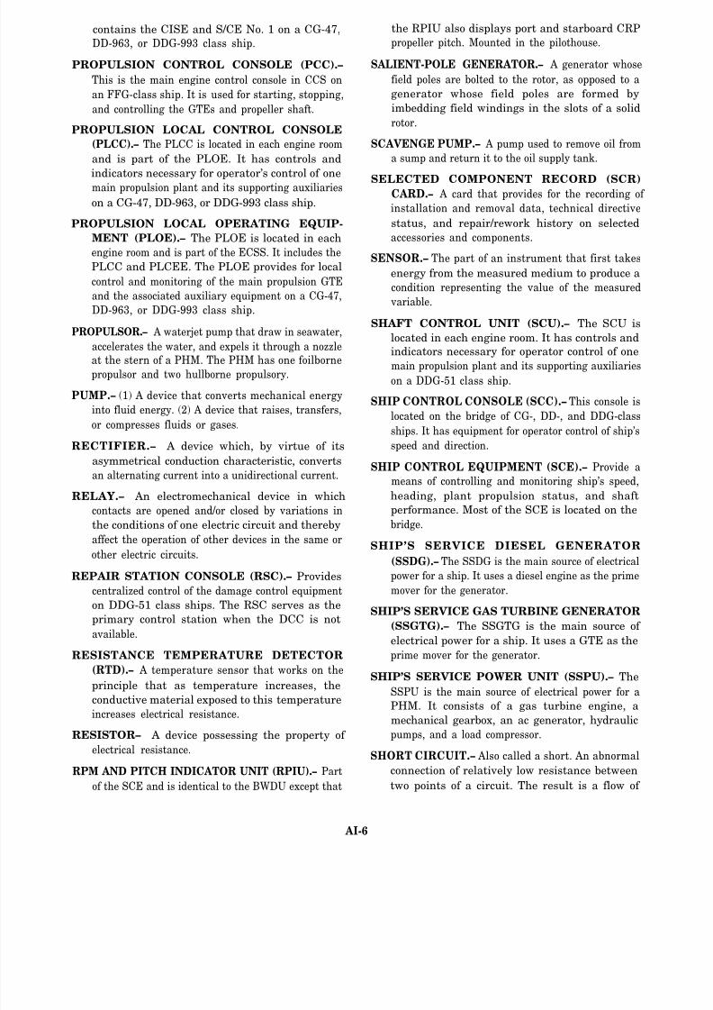
8/14/2019 US Navy Course NAVEDTRA 14115 - Gas Turbine Systems Technician Mechanical) 2
http://slidepdf.com/reader/full/us-navy-course-navedtra-14115-gas-turbine-systems-technician-mechanical 278/349
contains the CISE and S/CE No. 1 on a CG-47,
DD-963, or DDG-993 class ship.
PROPULSION CONTROL CONSOLE (PCC).–
This is the main engine control console in CCS on
an FFG-class ship. It is used for starting, stopping,
and controlling the GTEs and propeller shaft.
PROPULSION LOCAL CONTROL CONSOLE
(PLCC).– The PLCC is located in each engine room
and is part of the PLOE. It has controls and
indicators necessary for operator’s control of onemain propulsion plant and its supporting auxiliaries
on a CG-47, DD-963, or DDG-993 class ship.
PROPULSION LOCAL OPERATING EQUIP-
MENT (PLOE).– The PLOE is located in each
engine room and is part of the ECSS. It includes the
PLCC and PLCEE. The PLOE provides for local
control and monitoring of the main propulsion GTE
and the associated auxiliary equipment on a CG-47,
DD-963, or DDG-993 class ship.
PROPULSOR.– A waterjet pump that draw in seawater,
accelerates the water, and expels it through a nozzle
at the stern of a PHM. The PHM has one foilborne
propulsor and two hullborne propulsory.
PUMP.– (1) A device that converts mechanical energy
into fluid energy. (2) A device that raises, transfers,
or compresses fluids or gases.
RECTIFIER.– A device which, by virtue of its
asymmetrical conduction characteristic, converts
an alternating current into a unidirectional current.
RELAY.– An electromechanical device in which
contacts are opened and/or closed by variations in
the conditions of one electric circuit and thereby
affect the operation of other devices in the same or
other electric circuits.
REPAIR STATION CONSOLE (RSC).– Provides
centralized control of the damage control equipment
on DDG-51 class ships. The RSC serves as the
primary control station when the DCC is not
available.
RESISTANCE TEMPERATURE DETECTOR
(RTD).– A temperature sensor that works on the
principle that as temperature increases, the
conductive material exposed to this temperature
increases electrical resistance.
RESISTOR– A device possessing the property of
electrical resistance.
RPM AND PITCH INDICATOR UNIT (RPIU).– Part
of the SCE and is identical to the BWDU except that
the RPIU also displays port and starboard CRP
propeller pitch. Mounted in the pilothouse.
SALIENT-POLE GENERATOR.– A generator whose
field poles are bolted to the rotor, as opposed to a
generator whose field poles are formed by
imbedding field windings in the slots of a solid
rotor.
SCAVENGE PUMP.– A pump used to remove oil from
a sump and return it to the oil supply tank.
SELECTED COMPONENT RECORD (SCR)CARD.– A card that provides for the recording of
installation and removal data, technical directive
status, and repair/rework history on selected
accessories and components.
SENSOR.– The part of an instrument that first takes
energy from the measured medium to produce a
condition representing the value of the measured
variable.
SHAFT CONTROL UNIT (SCU).– The SCU is
located in each engine room. It has controls and
indicators necessary for operator control of onemain propulsion plant and its supporting auxiliaries
on a DDG-51 class ship.
SHIP CONTROL CONSOLE (SCC).– This console is
located on the bridge of CG-, DD-, and DDG-class
ships. It has equipment for operator control of ship’s
speed and direction.
SHIP CONTROL EQUIPMENT (SCE).– Provide a
means of controlling and monitoring ship’s speed,
heading, plant propulsion status, and shaft
performance. Most of the SCE is located on the
bridge.
SHIP’S SERVICE DIESEL GENERATOR
(SSDG).– The SSDG is the main source of electrical
power for a ship. It uses a diesel engine as the prime
mover for the generator.
SHIP’S SERVICE GAS TURBINE GENERATOR
(SSGTG).– The SSGTG is the main source of
electrical power for a ship. It uses a GTE as the
prime mover for the generator.
SHIP’S SERVICE POWER UNIT (SSPU).– The
SSPU is the main source of electrical power for a
PHM. It consists of a gas turbine engine, amechanical gearbox, an ac generator, hydraulic
pumps, and a load compressor.
SHORT CIRCUIT.– Also called a short. An abnormal
connection of relatively low resistance between
two points of a circuit. The result is a flow of
AI-6

8/14/2019 US Navy Course NAVEDTRA 14115 - Gas Turbine Systems Technician Mechanical) 2
http://slidepdf.com/reader/full/us-navy-course-navedtra-14115-gas-turbine-systems-technician-mechanical 279/349
excess (often damaging) current between these
points.
SIGNAL CONDITIONING ENCLOSURE (S/CE).–
Part of the PAMISE and provides the major
input interface between the propulsion plant
machinery and the ECSS control consoles. The
S/CE accepts inputs from the plant machinery
and outputs normalized signals to the ECSS
control consoles. Also has alarm detection and
alarm output circuitry. One S/CE is located in
each engine room and one is a part of the CISE
(located in CCS).
SILICON CONTROLLED RECTIFIER (SCR).– A
four layer pnpn semiconductor device that, when in
its normal state, blocks a voltage applied in either
direction. The SCR is enabled to conduct in the
forward direction when an appropriate signal is
applied to the gate electrode.
SOLDERING.– The joining of metallic surfaces (e.g.,
electrical contacts) by melting a metal or an alloy
(usually tin and lead) over them.
SOLENOID.– A coil of wire in the form of a long
cylinder that resembles a bar magnet. When current
flows in the wire, a movable core is drawn into the
coil .
SOLID-STATE.– (1) Pertaining to circuits and
components using semiconductors. (2) The physics
of materials in their solid form (e.g., diodes,
transistors, etc.).
SPLIT PLANT.– The condition in which only one
engine in an engine room is driving the reduction
gear/propulsion shaft.
STARTER AIR SYSTEM.– Takes both hot
compressed bleed air from the bleed air collection
and distribution system and cool compressed
bleed air from the masker air system and
distributes it to both the GTEs and GTGs for
starting and motoring.
STARTING AIR COMPRESSOR (SAC).– The
shaft-driven centrifugal compressor mounted on the
end of a diesel engine on the FFG-7 class ships. It
is used to supply compressed air to the GTEs for the
purpose of starting.
STATOR.– The nonrotating part of the magnetic
structure in an induction motor or a generator.
SUMMARY ALARM.– An indicator at a console that
indicates to an operator that one of several abnormal
conditions has occurred on a certain piece of
equipment.
SWITCHBOARD.– A single large panel or an
assembly of panels on which are mounted the
switches, circuit breakers, meters, fuses, and
terminals essential to the operation of electrical
equipment.
TACHOMETER.– An instrument used to measure the
speed of rotation of a device.
TEMPERATURE.– The quantitative measure of therelative hotness or coldness of an object.
THERMAL ENERGY.– The potential and kinetic
energy of particles of a body which can be evolved
as heat.
THERMOCOUPLE.– (1) a bimetallic device capable
of producing an emf roughly proportional to
temperature differences on its hot and cold
junction ends. (2) A junction of two dissimilar
metals that produces a voltage when the junction
is heated.
TOLERANCE.– The allowable deviation from a
specification or standard.
TRANSDUCER.– (1) A device that converts a
mechanical input signal into an electrical output
signal. (2) Generally, a device that converts energy
from one form into another, always retaining the
characteristic amplitude variations of the energy
converted.
TRANSFORMER.– A device composed of two or
more coils, linked by magnetic lines of force, used
to step up or step down an ac voltage.
TURBINE OVERTEMPERATURE PROTEC-
TION SYSTEM (TOPS).– A system used on a CG-
or DD-class ship to protect a surviving generator
from overload if another generator fails.
TURBINE INLET TEMPERATURE (TIT).– The
GTGS turbine inlet temperature on the Allison
501-K17. (Known as T5.4 for an LM2500 GTE.)
ULTRAVIOLET (UV) DETECTOR.– A device that
senses the presence of fire in the GTE and GTG
enclosure and generates an electrical signal that is
sent to the ECSS, MCS, or PCS.
UNINTERRUPTIBLE POWER SUPPLY (UPS)
SYSTEM.– Critical ship control systems have a
UPS as an emergency power source. The UPS is
used to maintain operations during any interruption
of the normal power source.
AI-7

8/14/2019 US Navy Course NAVEDTRA 14115 - Gas Turbine Systems Technician Mechanical) 2
http://slidepdf.com/reader/full/us-navy-course-navedtra-14115-gas-turbine-systems-technician-mechanical 280/349
VOLT.– A unit of electrical potential.
VOLTAGE.– An electric potential difference, ex-
pressed in volts.
VOLTAGE REGULATOR.– A circuit that holds an
output voltage at a predetermined value or causes it
to vary according to a predetermined plan,
regardless of normal input-voltage changes or
changes in the load.
WASTE HEAT BOILER (WHB).– Each waste heat
boiler is associated with a GTGS and uses the hot
exhaust gases to convert feedwater to steam for
various ship’s services on CG-, DD- or DDG-51
class ships.
WATT.– A unit of electric power equal to the rate of
work represented by a current of 1 ampere under a
pressure of 1 volt.
AI-8

8/14/2019 US Navy Course NAVEDTRA 14115 - Gas Turbine Systems Technician Mechanical) 2
http://slidepdf.com/reader/full/us-navy-course-navedtra-14115-gas-turbine-systems-technician-mechanical 281/349
APPENDIX II
ABBREVIATIONS AND ACRONYMS
A
ABT–automatic bus transfer
at–alternating current
ACC–auxiliary control console
A/C–air conditioning
ACS–automatic control system
A/D–analog-to-digital
AMR–auxiliary machinery room
AMS–alarm and monitor system
APD–automatic paralleling device
APL–allowance parts list
APU–auxiliary power unit
B
BCU–bridge control unit
BIT–built in test
BITE–built-in test equipment
BMEE–bulkhead mounted electronics enclosure
BWDU–bridge wing display unit
C
C&C–command and control
CB–circuit breaker
CCS–central control station
CNO–Chief of Naval Operations
COSAL–shipboard allowance list
CO–commanding officer
This appendix is a listing of the abbreviations and acronyms used in this text.
Although this is an extensive listing, it is not an all-inclusive list of abbreviations
and acronyms used by the Gas Turbine Systems Technicians. However, this list will
help form a basis for your qualification under the PQS system and allow for rapidaccess to terms used by Gas Turbine Systems Technicians.
CPP–controllable pitch propeller
CPR–cardiopulmonary resuscitation
CPU–central processing unit
CRP–controllable reversible pitch
CRT–cathode ray tube
CSEP–Control systems electronic package
D
dc–direct current
DCC–damage control console
DCU–data converter unit
DDI–demand display indicator
DMS–data multiplex system
DSP–disodium phosphate
DTG–date-time group
E
ECM–engine control module
ECSS–egineering control and surveillance system
ECU–executive control unit
EGL–equipment guide list
EIMB–electronics installation and maintenance book
EM–electrician’s mate
EMI–electromagnetic interference
EOCC–engineering operational causalty control
EOOW/LU–engineering officer of the watch/logging
unit
EOOW–engineering officer of the watch
AII-1

8/14/2019 US Navy Course NAVEDTRA 14115 - Gas Turbine Systems Technician Mechanical) 2
http://slidepdf.com/reader/full/us-navy-course-navedtra-14115-gas-turbine-systems-technician-mechanical 282/349
EOP–engineering operational procedures IMA–intermediate maintenance activity
EOS–engineer’s operating station
EOSS–engineering operational sequencing system
EOT–engine order telegraph
EPCC–electric plant control console
EPCE–electric plant control equipment
EPI–electronic pitch indicator
ESM–electronic support module
EXCOP–exciter control panel
F
FBCS–foilborne control system
FBR–feedback report
FECS–foilborne engine control system
FOD–foreign object damage
FPCS–foilborne propulsor control system
FSCC–fuel system control console
FSEE–free standing electronics enclosure
G
GCU–generator control unit
GS–gas turbine systems technician
GSE–gas turbine systems technician (electrical)
GT–gas turbine
GTB–gas turbine bulletin
GTC–gas turbine change
GTE–gas turbine engine
GTGS–gas turbine generator set
H
HBCS–hullborne control system
hp–horsepower
HSVL–high speed velocity log
Hz–hertz
I
IC–interior communication electrician
IIEC–interim integrated electronic control
in.lb–inch pound
in.H 2O–inches of water
I/O-input/output
ITC-integrated throttle control
K
kW–kilowatt
L
LCAC–landing craft, air cushion
LED–light emitting diode
LOCOP–local control panel
LOP–local operating panel
LVP–low-voltage protection
LVR–low-voltage release
M
mA–milliampere
MBT–manual bus transfer
MCS–machinery control system
MER–main engine room
MGT–marine gas turbine
MGTE–marine gas turbine engine
MGTESR–marine gas turbine equipment service record
MIP–maintenance index page
MLSG–mobile logistic support group
MRC–maintenance requirement card
MRG–main reduction gear
N
NAVSEACEN–naval sea support center
NRTC–nonresident training courseNSTM–naval ships’ technical manual
O
OD–oil distribution
OOD–officer of the deck
AII-2

8/14/2019 US Navy Course NAVEDTRA 14115 - Gas Turbine Systems Technician Mechanical) 2
http://slidepdf.com/reader/full/us-navy-course-navedtra-14115-gas-turbine-systems-technician-mechanical 283/349
P
PACC–propulsion and auxiliary control console
PAMCE–propulsion and auxiliary machinery control
equipment
PAMISE–propulsion and auxiliary machinery
information system
PCBæprinted circuit board
PCC–propulsion control console
PCS–propulsion control system
PDU–plasma display unit
PHM–patrol combatant missile (hydrofoil)
PLA–power lever angle
PLCC–propulsion local control console
PLOE–propulsion local operating equipment
PMA–permanent magnet alternator
PMS–planned maintenance system
PQS–personnel qualification standard
psi–pounds per square inch
psia–pounds per square inch absolute
psid–pounds per square inch differential
psig–pounds per square inch gauge
PT–power turbine
PWB–printed wiring board
Q
QA–quality assurance
QAO–quality assurance officer
R
RAM–random access memory
ROM–read only memory
RPIU–rpm and pitch indicator unit
rpm–revolutions per minute
RTD–resistance temperature detector
RTE–resistance temperature element
S
SAC–start air compressors
SCC–ship control console
SCE–ship control equipment
S/CE–signal conditioning enclosureSCR–silicon controlled rectifier
SCS–supervisory control system
SCU–shaft control unit
SEM–standard electronic module
SIMA–shore intermediate maintenance activity
SMR–source, maintenance, and recoverability
SQCI–ship quality control inspector
SSDG–ship’s service diesel generator
SSGTG–ship’s service gas turbine generator
SSPU–ship’s service power unit
T
TCPI–temperature compensated pitch indicator
TD–technical directive
TIT–turbine inlet temperature
TLI–tank level indicator
TOPS–turbine overload protection system
TRAMAN–training manual
TSP–trisodium phosphate
TYCOM–type commander
U
UPS–uninterrupted power supply
W
WHB–waste heat boiler
AII-3

8/14/2019 US Navy Course NAVEDTRA 14115 - Gas Turbine Systems Technician Mechanical) 2
http://slidepdf.com/reader/full/us-navy-course-navedtra-14115-gas-turbine-systems-technician-mechanical 284/349

8/14/2019 US Navy Course NAVEDTRA 14115 - Gas Turbine Systems Technician Mechanical) 2
http://slidepdf.com/reader/full/us-navy-course-navedtra-14115-gas-turbine-systems-technician-mechanical 285/349
APPENDIX III
ELECTRICAL SYMBOLS
AIII-1

8/14/2019 US Navy Course NAVEDTRA 14115 - Gas Turbine Systems Technician Mechanical) 2
http://slidepdf.com/reader/full/us-navy-course-navedtra-14115-gas-turbine-systems-technician-mechanical 286/349
AIII-2

8/14/2019 US Navy Course NAVEDTRA 14115 - Gas Turbine Systems Technician Mechanical) 2
http://slidepdf.com/reader/full/us-navy-course-navedtra-14115-gas-turbine-systems-technician-mechanical 287/349

8/14/2019 US Navy Course NAVEDTRA 14115 - Gas Turbine Systems Technician Mechanical) 2
http://slidepdf.com/reader/full/us-navy-course-navedtra-14115-gas-turbine-systems-technician-mechanical 288/349

8/14/2019 US Navy Course NAVEDTRA 14115 - Gas Turbine Systems Technician Mechanical) 2
http://slidepdf.com/reader/full/us-navy-course-navedtra-14115-gas-turbine-systems-technician-mechanical 289/349
APPENDIX IV
PIPING PRINT SYMBOLS
AIV-1

8/14/2019 US Navy Course NAVEDTRA 14115 - Gas Turbine Systems Technician Mechanical) 2
http://slidepdf.com/reader/full/us-navy-course-navedtra-14115-gas-turbine-systems-technician-mechanical 290/349
AIV-2

8/14/2019 US Navy Course NAVEDTRA 14115 - Gas Turbine Systems Technician Mechanical) 2
http://slidepdf.com/reader/full/us-navy-course-navedtra-14115-gas-turbine-systems-technician-mechanical 291/349
AIV-3

8/14/2019 US Navy Course NAVEDTRA 14115 - Gas Turbine Systems Technician Mechanical) 2
http://slidepdf.com/reader/full/us-navy-course-navedtra-14115-gas-turbine-systems-technician-mechanical 292/349

8/14/2019 US Navy Course NAVEDTRA 14115 - Gas Turbine Systems Technician Mechanical) 2
http://slidepdf.com/reader/full/us-navy-course-navedtra-14115-gas-turbine-systems-technician-mechanical 293/349
APPENDIX V
METRIC SYSTEM
Table AV-1.-Decimal System Prefixes
AV-1

8/14/2019 US Navy Course NAVEDTRA 14115 - Gas Turbine Systems Technician Mechanical) 2
http://slidepdf.com/reader/full/us-navy-course-navedtra-14115-gas-turbine-systems-technician-mechanical 294/349
Table AV-2.-Metric Conversions
AV-2
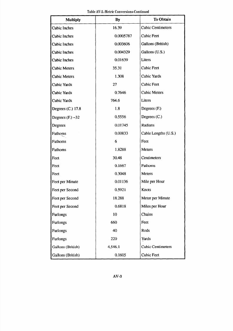
8/14/2019 US Navy Course NAVEDTRA 14115 - Gas Turbine Systems Technician Mechanical) 2
http://slidepdf.com/reader/full/us-navy-course-navedtra-14115-gas-turbine-systems-technician-mechanical 295/349
Table AV-2.-Metric Conversions-Continued
AV-3

8/14/2019 US Navy Course NAVEDTRA 14115 - Gas Turbine Systems Technician Mechanical) 2
http://slidepdf.com/reader/full/us-navy-course-navedtra-14115-gas-turbine-systems-technician-mechanical 296/349
Table AV-2.-Metric Conversion–Continued
AV-4

8/14/2019 US Navy Course NAVEDTRA 14115 - Gas Turbine Systems Technician Mechanical) 2
http://slidepdf.com/reader/full/us-navy-course-navedtra-14115-gas-turbine-systems-technician-mechanical 297/349
Table AV-2.-Metric Conversions–Continued
AV-5

8/14/2019 US Navy Course NAVEDTRA 14115 - Gas Turbine Systems Technician Mechanical) 2
http://slidepdf.com/reader/full/us-navy-course-navedtra-14115-gas-turbine-systems-technician-mechanical 298/349
Table AV-2.-Metric Conversions–Continued
AV-6

8/14/2019 US Navy Course NAVEDTRA 14115 - Gas Turbine Systems Technician Mechanical) 2
http://slidepdf.com/reader/full/us-navy-course-navedtra-14115-gas-turbine-systems-technician-mechanical 299/349
Table AV-2.-Meric Conversions–Continued

8/14/2019 US Navy Course NAVEDTRA 14115 - Gas Turbine Systems Technician Mechanical) 2
http://slidepdf.com/reader/full/us-navy-course-navedtra-14115-gas-turbine-systems-technician-mechanical 300/349
Table AV-2.-Metric Conversion–Continued
AV-8

8/14/2019 US Navy Course NAVEDTRA 14115 - Gas Turbine Systems Technician Mechanical) 2
http://slidepdf.com/reader/full/us-navy-course-navedtra-14115-gas-turbine-systems-technician-mechanical 301/349
APPENDIX VI
LIST OF NAVY ELECTRICITY ANDELECTRONICS TRAINING SERIES
Module 1
Module 2
Module 3
Module 4
Module 5
Module 6
Module 7
Module 8
Module 9
Module 10
Module 11
Module 12
Module 13
Module 14
Module 15
Module 16
Module 17
Introduction to Matter, Energy, and Direct Current
Introduction to Alternating Current and Transformers
Introduction to Circuit Protection, Control, and Measure-
ments
Introduction to Electrical Conductors, Wiring Techniques,
and Schematic Reading
Introduction to Generators and Motors
Introduction to Electronic Emission, Tubes, and Power
Supplies
Introduction to Solid-State Devices and Power Supplies
Introduction to Amplifiers
Introduction to Wave-Generation and Wave-Shaping Circuits
Introduction to Wave Propagation, Transmission Lines, and Antennas
Microwave Principles
Modulation Principles
Introduction to Number Systems and Logic Circuits
Introduction to Microelectronics
Principles of Synchros, Servos, and Gyros
Introduction to Test Equipment
Radio-Frequency Communications Principles
AVI-1

8/14/2019 US Navy Course NAVEDTRA 14115 - Gas Turbine Systems Technician Mechanical) 2
http://slidepdf.com/reader/full/us-navy-course-navedtra-14115-gas-turbine-systems-technician-mechanical 302/349
Module 18 Radar Principles
Module 19 The Technician’s Handbook
Module 20 Master Glossary and Index
Module 21 Test Methods and Practices
Module 22 Introduction to Digital Computers
Module 23 Magnetic Recording
Module 24 Introduction to Fiber Optics
AVI-2

8/14/2019 US Navy Course NAVEDTRA 14115 - Gas Turbine Systems Technician Mechanical) 2
http://slidepdf.com/reader/full/us-navy-course-navedtra-14115-gas-turbine-systems-technician-mechanical 303/349

8/14/2019 US Navy Course NAVEDTRA 14115 - Gas Turbine Systems Technician Mechanical) 2
http://slidepdf.com/reader/full/us-navy-course-navedtra-14115-gas-turbine-systems-technician-mechanical 304/349
Naval S hips’ Technical Man ual, 0901-LP-420-0002, Chapter 9420, “Propulsion
Reduction Gears, Couplings, and Associated Components,” Naval Sea Systems
Command, Washington, D.C., 15 August 1985.
S hip’s Maintenan ce and M aterial Management (3-M) Manu al, OPNAVINST
4790.4B, Office of the Chief of Naval Operations, Washington, D.C., 13 August
1987.
S tandard Organization an d Regulations of the U.S . Navy, OPNAVINST 3132.32B,
Office of the Chief of Naval Operations, Washington, D.C., 26 September 1986.
Chapter 2
Engineering Administration, NAVEDTRA 10858-F1, Naval Education and
Training Program Management Support Activity, Pensacola, Fla., April 1988.
Naval S hips’ Technical Man ual, S9086-GX-STM-020, Chapter 220, “Boiler
Water/Feedwater Test and Treatment,” Volume 2, Naval Sea Systems
Command, Washington, D.C., 15 December 1987.
Naval S hips’ Technical Man ual, S9086-HB-STM-000, Chapter 233, “Diesel
Engines,” Naval Sea Systems Command, Washington, D.C., 15 June 1987.
Naval S hips’ Technical Manua l, S9086-HC-STM-000, Chapter 234, “Marine Gas
Turbines,” Naval Sea Systems Command, Washington, D.C., 15 August 1988.
Naval S hips’ Technical Manu al, S9086-H7-STM-010, Chapter 262, “Lubricating
Oils, Greases, Hydraulic Fluids and Lubrication Systems,” Naval Sea Systems
Command, Washington, D.C., 15 September 1987.
Naval S hips’ Technical Manu al, S9086-KC-STM-010, Chapter 300 R2, “Electric
Plant-General,” Naval Sea Systems Command, Washington, D.C., 28 February
1991.
Naval S hips’ Technical Man ual, S9086-SN-STM-000, Chapter 541, “Petroleum
Fuel Stowage, Use, and Testing,” Naval Sea Systems Command, Washington,
D.C., 1 September 1986.
Naval S hips’ Technical Manu al, S9086-SP-STM-010, Chapter 542, “Gasoline andJP-5 Fuel Systems,” Naval Sea Systems Command, Washington, D.C., 28
September 1990.
Chapter 3
Gas Turbin e S ystems Technician (Electrical) 3/ Gas Turbin e Systems T echn ician
(Mechanical) 3, Volume 2, NAVEDTRA 10564, Naval Education and Training
program Management Support Activity, Pensacola, Fla., September 1989.
Propulsion Plant Manu al, “propulsion Plant System for CG-47 Class Ships,”
Volume 4, S9234-D8-GTP-040/CG-47 PPM, Naval Sea Systems Command,
Washington, D.C., 15 December 1990.
Propulsion Plant Man ual, “propulsion Plant System for DD-963 Class Ships,”
Volume 4, S9234-AL-GTP-040/DD-963 PPM, Naval Sea Systems Command,
Washington, D.C., 1 March 1990.
Propulsion Plant Manual, “Propulsion Plant System for DDG-51 Class Ships,”
Volume 4, S9234-GA-GTP-040/DDG-51 PPM, Naval Sea Systems Command,
Washington, D.C., 1 February 1991.
AVII-2

8/14/2019 US Navy Course NAVEDTRA 14115 - Gas Turbine Systems Technician Mechanical) 2
http://slidepdf.com/reader/full/us-navy-course-navedtra-14115-gas-turbine-systems-technician-mechanical 305/349
Propulsion Plant Manu al, “propulsion Plant System for FFG-7 Class Ships,”
Volume 4, S9234-BL-GTP-040/FFG-7 PPM, Naval Sea Systems Command,
Washington, D.C., 15 August 1984.
Chapter 4
Gas Turbine Systems Technician (Mechanical) 2 & 3, NAVEDTRA 10548-2, Naval
Education and Training Program Management Support Activity, Pensacola,
Fla., August 1988. Naval Ships Technical Manual. S9086-GY-STM-010, Chapter 221, “Boilers,”
Naval Sea Systems Command, Washington, D.C., 15 September 1990.
Naval S hips’ Technical Man ual, S9086-RK-STM-010, Chapter 505, “Piping
Systems,” Naval Sea Systems Command, Washington, D.C., 15 April 1988.
Naval S hips’ Technical Manu al, S9086-SY-STM-010, Chapter 551, “Compressed
Air Plants and Systems,” Naval Sea Systems Command, Washington, D.C., 15
September 1989.
Naval S hips’ Technical Manu al, S9253-AD-MMM-010, “Maintenance For Valves,
Traps, and Orifices (Non-Nuclear),” Volume 2, Naval Sea Systems Command,
Washington, D.C., 15 April 1988.
Propulsion Plant Manual, “Propulsion Plant System for CG-47 Class Ships,”
Volume 1, S9234-D8-GTP-010/CG-47 PPM, Naval Sea Systems Command,
Washington, D.C., 15 December 1990.
Propulsion Plant Manu al, “Propulsion Plant System for CG-47 Class Ships,”
Volume 2, S9234-D8-GTP-020/CG-47 PPM, Naval Sea Systems Command,
Washington, D.C., 15 December 1990.
Propulsion Plant Man ual, “Propulsion Plant System for CG-47 Class Ships,”
Volume 3, S9234-D8-GTP-030/CG-47 PPM, Naval Sea Systems Command,
Washington, D.C., 15 December 1990.
Propulsion Plant Manu al, “Propulsion Plant System for DD-963 Class Ships,”
Volume 1, S9234-AL-GTP-010/DD-963 PPM, Naval Sea Systems Command,Washington, D.C., 1 April 1991.
Propulsion Plant Manu al, “Propulsion Plant System for DD-963 Class Ships,”
Volume 2, S9234-AL-GTP-020/DD-963 PPM, Naval Sea Systems Command,
Washington, D.C., 15 February 1991.
Propulsion Plant Manu al, “Propulsion Plant System for DD-963 Class Ships,”
Volume 3, S9234-AL-GTP-030/DD-963 PPM, Naval Sea Systems Command,
Washington, D.C., 1 March 1991.
Propulsion Plant Man ual, “Propulsion Plant System for DD-963 Class Ships,”
Volume 4, S9234-AL-GTP-040/DD-963 PPM, Naval Sea Systems Command,
Washington, D.C., 1 March 1990.
Propulsion Plant Man ual, “Propulsion Plant System for DDG-51 Class Ships,”
Volume 1, S9234-GA-GTP-010/DD-51 PPM, Naval Sea Systems Command,
Washington, D.C., 1 February 1991.
Propulsion Plant Manu al, “Propulsion Plant System for DDG-51 Class Ships,”
Volume 2, S9234-GA-GTP-020/DD-51 PPM, Naval Sea Systems Command,
Washington, D.C., 1 February 1991.
AVII-3

8/14/2019 US Navy Course NAVEDTRA 14115 - Gas Turbine Systems Technician Mechanical) 2
http://slidepdf.com/reader/full/us-navy-course-navedtra-14115-gas-turbine-systems-technician-mechanical 306/349
Propulsion Plant Man ual, “Propulsion Plant System for FFG-7 Class Ships,”
Volume 1, S9234-BL-GTP-010/FFG-7 PPM, Naval Sea Systems Command,
Washington, D.C., 15 January 1992.
Propulsion Plant Manual, “Propulsion Plant System for FFG-7 Class Ships,”
Volume 3, S9234-BL-GTP-030/FFG-7 PPM, Naval Sea Systems Command,
Washington, D.C., 15 August 1984.
Propulsion Plant Manual, “Propulsion Plant System for FFG-7 Class Ships,”
Volume 4, S9234-BL-GTP-040/FFG-7 PPM, Naval Sea Systems Command,
Washington, D.C., 1 March 1992.
Chapter 5
Electronic Installation and Maintenance Book, General, NAVSEA SE000-00-
EIM-100, Naval Sea Systems Command, Washington, D.C., April 1983.
Gas Turbine Systems Technician (Mechanical) 2 & 3, NAVEDTRA 10548-2, Naval
Education and Training Program Management Support Activity, Pensacola,
Fla., August 1988.
Naval S hips’ Technical Man ual, S9243-A7-MMA-010/77842, “Stern Tube Seal,”
Naval Sea Systems Command, Washington, D.C., 14 April 1989.
Naval S hips’ Technical Manual, S9244-AT-MMA-010, “Propulsion Line Shaft
Bearing, Oil Disc Lubricated,” Naval Sea Systems Command, Washington,
D.C., 14 April 1989.
Naval S hips’ Technical Man ual, S9086-HN-STM-010, Chapter 244, “Propulsion
Bearings and Seals,” Naval Sea Systems Command, Washington, D.C., 31 July
1991.
Naval S hips’ Technical Manua l, S9086-KC-STM-010, Chapter 300 R2, “Electric
Plant-General,” Naval Sea Systems Command, Washington, D.C., 28 February
1991.
Naval S hips’ Technical Man ual, 0901-LP-420-0002, Chapter 9420, “Propulsion
Reduction Gears, Couplings, and Associated Components,” Naval Sea Systems
Command, Washington, D.C., 15 August 1985.
Naval S hips’ Technical Man ual, 0901-LP-430-0012, Chapter 9430, “Shafting,
Bearings, and Seals,” Naval Sea Systems Command, Washington, D.C., 15
August 1985.
Propulsion Plan t Man ual, “Propulsion Plant System for CG-47 Class Ships,”
Volume 1, S9234-D8-GTP-010/CG-47 PPM, Naval Sea Systems Command,
Washington, D.C., 15 December 1990.
Propulsion Plant Manual, “Propulsion Plant System for DDG-51 Class Ships,”
Volume 1, S9234-GA-GTP-010/DDG-51 PPM, Naval Sea Systems Command,
Washington, D.C., 1 February 1991.
Propulsion Plant Manu al, “Propulsion Plant System for FFG-7 Class Ships,”
Volume 1, S9234-BL-GTP-010/FFG-7 PPM, Naval Sea Systems Command,
Washington, D.C., 15 January 1992.
AVII-4

8/14/2019 US Navy Course NAVEDTRA 14115 - Gas Turbine Systems Technician Mechanical) 2
http://slidepdf.com/reader/full/us-navy-course-navedtra-14115-gas-turbine-systems-technician-mechanical 307/349
Chapter 6
AC Generator, S6265-AB-MMO-010/977J031-2/3, Naval Sea Systems Command,
Washington, D.C., 1 December 1989.
Electrician’s M ate 3 & 2, NAVEDTRA 10546-F, Naval Education and Training
Program Management Support Activity, Pensacola, Fla., July 1988.
Gas T urbin e Generator S et, Model 831-800 S eries, S9234-EL-MMO-010/MOD
ME831-800, Naval Sea Systems Command, Washington, D.C., 15 March 1986.
Gas Turbin e S ystems Technician (Electrical) 3/ Gas Turbine S ystems Technician
(Mechanical) 3, Volume 1, NAVEDTRA 10563, Naval Education and Training
program Management Support Activity, Pensacola, Fla., September 1989.
Gearbox Assembly, S9567-AD-MMO-010/ P/N 44267R1, Naval Sea Systems
Command, Washington, D.C., 31 December 1991.
IC Electrician 3, NAVEDTRA 10559-A, Naval Education and Training Program
Management Support Activity, Pensacola, Fla., May 1989.
Instrumentman 3 & 2, NAVEDTRA 10193-D, Naval Education and Training
Program Management Support Activity, Pensacola, Fla., January 1986.
Landing Craft, Air Cushion (LCAC) Craft Control Systems, S9568-AK-MMA-010,
Naval Sea Systems Command, Washington, D.C., 15 April 1991.
Mobile Electric Power Plant, SG320-AA-MMO-010/90911, Naval Sea Systems
Command, Washington, D.C., 15 March 1985.
Propulsion Gas Turbine Module LM5200, Trouble Isolation, Volume 2, Part 1,
S9234-AD-MMO-030/LM2500, Naval Sea Systems Command, Washington,
D.C., 30 September 1991.
Propulsion Gas Turbine Module LM5200, Trouble Isolation, Volume 2, Part 3,
S9234-AD-MMO-050/LM2500, Naval Sea Systems Command, Washington,
D.C., 30 September 1991.
S y s t e m O p e r a t i o n a n d O n b o a r d M a i n t e n a n c e P H M - 3 S e r i e s ,
S9PHM-AC-SHP-010/(U) PHM-3 CL, Naval Sea Systems Command,
Washington, D.C., 1 May 1991.
S y s t e m O p e r a t i o n a n d O n b o a r d M a i n t e n a n c e P H M - 3 S e r i e s ,
S9PHM-AC-SHP-020/(U) PHM-3 CL, Naval Sea Systems Command,
Washington, D.C., 1 October 1990.
S y s t em O p e ra t i on a n d O n b oa rd M a i n ten a n ce P H M -3 S er ies ,
S9PHM-AC-SHP-030/(U) PHM-3 CL, Naval Sea Systems Command,
Washington, D.C., 1 November 1991.
S y s t em O p er a t ion a n d O n b oa r d M a i n t en a n c e P H M -3 S er i es ,
S9PHM-AC-SHP-040/(U) PHM-3 CL, Naval Sea Systems Command,
Washington, D.C., 1 May 1991.
S y s t em O p e ra t i on a n d O n b oa rd M a i n ten a n ce PH M -3 S er ies ,
S9PHM-AC-SHP-050/(U) PHM-3 CL, Naval Sea Systems Command,
Washington, D.C., 1 November 1991.
AVII-5

8/14/2019 US Navy Course NAVEDTRA 14115 - Gas Turbine Systems Technician Mechanical) 2
http://slidepdf.com/reader/full/us-navy-course-navedtra-14115-gas-turbine-systems-technician-mechanical 308/349
Chapter 7
Gas Turbine Generator Set, Model 831-800 Series, S9234-EL-MMO-010/MOD
ME831-800, Naval Sea Systems Command, Washington, D.C., 15 March 1986.
Naval S hips’ Techn ical Man ual, S9234-D1-GTP-010, “Internal Inspection and
Evaluation of Marine Gas Turbine Engines,” Naval Sea Systems Command,
Washington, D.C., 15 October 1982.
Naval S hips’ Techn ical Man ual, S9311-A3-MMA-010, “Operational and
Maintenance Manual For Auxiliary Power Unit (APU) System/Installation,”Naval Sea Systems Command, Washington, D.C., 15 July 1991.
Propulsion Plant Manual, “Propulsion Plant System for CG-47 Class Ships;
Volume 2, S9234-D8-GTP-020/CG-47 PPM, Naval Sea Systems Command,
Washington, D.C. 15 December 1990.
Propulsion Plant Man ual, “Propulsion Plant System for DDG-51 Class Ships,”
Volume 2, S9234-GA-GTP-020/DD-51 PPM, Naval Sea Systems Command,
Washington, D.C. 1 February 1991.
Propulsion Plant Manual, “propulsion Plant System for FFG-7 Class Ships,”
Volume 2, S9234-BL-GTP-020/FFG-7 PPM, Naval Sea Systems Command,
Washington, D.C., 15 January 1992.
AVII-6

8/14/2019 US Navy Course NAVEDTRA 14115 - Gas Turbine Systems Technician Mechanical) 2
http://slidepdf.com/reader/full/us-navy-course-navedtra-14115-gas-turbine-systems-technician-mechanical 309/349
INDEX
A
Administrative duties, responsibilities, and require-
ments, 1-16
disposal procedures, 1-16
verification procedures,1-16
Allison 501-K17 and 501-K34, 7-1 to 7-9
engine foundation and enclosure, 7-2
EXCOP, 7-4
GTGS design and operation, 7-1
hand pump assembly, 7-9
LOCOP, 7-5
Automatic control valves and components, 4-3 to 4-11,
4-23
level control valves, 4-5maintenance and repair, 4-9 to 4-11
mechanical linkage, 4-5,4-9
pressure control valves, 4-7 to 4-10
temperature control valves, 4-3,4-6,4-23
valve actuators, 4-4
AVCO Lycoming TF40B GTE, 6-1 to 6-7
B
Bleed air systems, 4-12 to 4-20
anti-icing air, 4-20
collection and distribution, 4-13
masker and prairie air, 4-14
start air, 4-15
Boiler water, 2-26 to 2-30
contamination control, 2-27 to 2-30
test procedures, 2-28
treatment, 2-28 to 2-30
C
Casualty control, 3-30
CCS operations (FFG-7), 3-22 to 3-30
ACC, 3-29
EPCC, 3-25 to 3-28
PCC, 3-22 to 3-25
CCS operations, CG-47, DD-963, and DDG-993 ships,
3-2 to 3-11
PACC, 3-2 to 3-7
EPCC, 3-7 to 3-11
CCS operations, DDG-51, 3-11 to 3-22
EOOW/LU, 3-20 to 3-22
EPCC, 3-16 to 3-19
PACC, 3-12 to 3-16
Chemicals, 2-3
fuel and oil test chemicals, 2-3
water chemicals, 2-3
Clutch and brake assemblies, 5-18 to 5-20
alignments and adjustments, 5-20
maintenance, 5-19
replacement of components, 5-20
troubleshooting, 5-20
Contamination control, 2-26 to 2-32
boiler water, 2-26 to 2-30feedwater, 2-32
Controllable pitch propeller system, 5-9 to 5-15
replacement of components, 5-13
troubleshooting and maintenance, 5-15
D
Daily records and reports, 1-16
Detroit diesel 16V149, 7-38 to 7-45
Diagrams and equipment layouts, 1-20 to 1-22
common terms and symbols, 1-20
equipment layouts, 1-22
machine drawings and system diagrams, 1-21
INDEX-1

8/14/2019 US Navy Course NAVEDTRA 14115 - Gas Turbine Systems Technician Mechanical) 2
http://slidepdf.com/reader/full/us-navy-course-navedtra-14115-gas-turbine-systems-technician-mechanical 310/349
Diesel lube oil testing, 2-21 to 2-22
fuel dilution and oil thickening test, 2-21
oil acidity test, 2-21
Drive train equipment, 5-15 to 5-25
clutch and brake assemblies, 5-18 to 5-20
main reduction gear, 5-15 to 5-18
shafting and bearings, 5-20 to 5-25
E
Electric plant configurations,
DDG-993 ships, 3-9
emergency, 3-10
nonstandard, 3-10
standard parallel, 3-10
standard split, 3-9
CG-47, DD-963, and
Electrical plant, routine maintenance and repairs of,
7-45 to 7-61
generators and reduction gears, 7-55
GTE, 7-45
safety, 7-45
Engineering logs, records, and reports, 1-3 to 1-19
administrative duties, responsibilities, and require-
ments, 1-16
daily records and reports, 1-16
equipment guide lists, 1-19
files and tickler systems, 1-17
FO and logs, 1-4
legal records, 1-4
marine gas turbine records 1-4 to 1-13
operating records, 1-4 to 1-17
PMS feedback reports 1-18
EOOW/LU, 3-20 to 3-22
EPCC (FFG-7), 3-25 to 3-28
EPCC, CG-47, DD-963, and DDG-993 ships, 3-7 to
3-11
EPCC, DDG-51, 3-16 to 3-19
F
F-44 (JP-5) test equipment and procedures, 2-12 to 2-18
FSII refractometer kit, 2-17
FSII test procedures, 2-17
F-44 (JP-5) testing, 2-16 to 2-18
equipment and procedures, 2-16 to 2-18
requirements, 2-16
sampling, 2-16
F-76 (naval distillate) sampling, 2-10 to 2-12
F-76 (naval distillate) testing, 2-12 to 2-16
API gravity test, 2-13
BS & W test, 2-12
flash point test, 2-13
free water test, 2-16
requirements and conditions, 2-12
solids contamination test, 2-14 to 2-16
sources, 2-12
water contamination test, 2-14
Feedwater contaminants and control, 2-31
Files and tickler systems, 1-17
Fuel oil test logs, 2-33
G
Garrett, ME 831-800A, 7-9 to 7-25
Generator and reduction gears. 7-56 to 7-61
cooling systems, 7-59
maintenance and repair, 7-56 to 7-61
oil systems, 7-56
GTE maintenance and repairs, 7-47 to 7-55
accessory gearbox, 7-50
borescoping, 7-51
cleaning, 7-47
combustor, 7-49
compressor, 7-48
turbine, 7-50
INDEX-2

8/14/2019 US Navy Course NAVEDTRA 14115 - Gas Turbine Systems Technician Mechanical) 2
http://slidepdf.com/reader/full/us-navy-course-navedtra-14115-gas-turbine-systems-technician-mechanical 311/349
H
Handling hazardous materials, 2-1 to 2-5
chemicals, 2-3
hazardous wastes, 2-3 to 2-5
petroleum products, 2-1 to 2-3
Hazardous wastes, 2-3 to 2-5
J
JP-5, 2-12 to 2-18. S ee F-44
L
Landing craft, air cushion, 6-1 to 6-25
AVCO Lycoming TF40B GTE, 6-1
electrical system, 6-19
control systems, 6-7maintenance, 6-23
LCAC control systems, 6-7 to 6-19
lift fan control, 6-13
propeller pitch control, 6-12
steering control, 6-8
TF40B GTE control, 6-16
LCAC electrical system, 6-19 to 6-23
APU (generator set), 6-21distribution, 6-22
LCAC maintenance, 6-23 to 6-25
Low-pressure air compressors, 4-1 to 4-3
Lube oil system, main reduction gear, 5-6 to 5-9
monitoring and troubleshooting, 5-7
replacement of components, 5-9
tests and inspections, 5-7
Lube oil test logs, 2-34
M
Machine drawings and system diagrams, 1-21
Main reduction gears, maintenance of , 5-15 to 5-18
Marine gas turbine records, 1-4 to 1-13
Mineral oil, 2-18 to 2-21
sampling, 2-19
testing of, 2-20
O
Oil laboratory logs and records, 2-32 to 2-42
bw/fw test and treatment chemical inventory log,
2-39
fuel and water report, 2-39
fuel oil test logs, 2-33
jacket water test log, 2-32
lube oil test logs, 2-34
water treatment logs, 2-34 to 2-42
Oil types, 2-22
Operating and monitoring laboratory test equipment,2-5 to 2-10
AEL Mk I/II and III, 2-7
boiler water testing cabinet, 2-9
centrifuge, 2-7
conductivity meter, 2-9
flash point tester, 2-8
P
PACC, CC-47, DD-963, DDG-993 ships, 3-2 to 3-7
PACC DDG-51, 3-12 to 3-16
Patrol combatant missile (hydrofoil), 6-25 to 6-47
auxiliary subsystem, 6-44
electrical subsystem, 6-39
main propulsion (Foilborne) subsystem, 6-26
main propulsion (hullborne) subsystem, 6-35
PHM maintenance, 6-46
PCC (FFG-7), 3-22 to 3-25
PHM auxiliary systems, 6-44 to 6-46
PHM electrical system, 6-39 to 6-44
ac generator, 6-42
electrical distribution. 6-43
INDEX-3

8/14/2019 US Navy Course NAVEDTRA 14115 - Gas Turbine Systems Technician Mechanical) 2
http://slidepdf.com/reader/full/us-navy-course-navedtra-14115-gas-turbine-systems-technician-mechanical 312/349
PHM main propulsion (foilborne), 6-26 to 6-35
control systems and operating stations, 6-29
LM2500 GTE, 6-27
power train assembly, 6-28
propulsor assembly, 6-28
PHM main propulsion (hullborne), 6-35 to 6-37
control system, 6-37
major assemblies, 6-36
PMS feedback reports, 1-18
Prime movers, 7-1,7-9,7-25,7-38
Allison 501-K17 and 501-K34, 7-1
Detroit diesel 16V - 149,7-38
Garrett ME 831-800A, 7-9
Sunstrand T-62T-40-7, 7-25
Propulsion plant systems, 5-1 to 5-15
controllable pitch propeller system, 5-9 to 5-15
fuel oil system ship’s service, 5-1 to 5-6
lube oil system main reduction gear, 5-6 to 5-9
Propulsion shafting and bearings, maintenance of, 5-20
to 5-25
Q
Quality assurance program, 1-1
goals, 1-1manual, 1-1
organization, 1-2
specifications, 1-20
R
Records, marine gas turbine, 1-4 to 1-13
cover sheet, 1-5
custody and transfer record, 1-5
inspection record, 1-7
miscellaneous/history, 1-9
operating log, 1-7
rework record, 1-9
selected component records, 1-9
Records, marine gas turbine–Continued
supplemental records, 1-10 to 1-13
technical directions, 1-9
Records, operating, 1-13 to 1-17
air compressors, 1-14
diesel engines, 1-13
distilling plant, 1-14
reduction gear, 1-13
refrigeration/air conditioning plants, 1-14
Reduction gear assemblies electric plant, 7-59 to 7-61
S
Safety precautions, 2-1 to 2-10
handling and monitoring hazardous materials, 2-1
to 2-5
Sampling and testing, 2-10 to 2-33
fuels, 2-10 to 2-18
oils, 2-18 to 2-22
waste heat water testing, 2-32
Ship’s service fuel oil system, 5-1 to 5-6
maintenance and troubleshooting, 5-1
replacement of components, 5-6
tests and inspections, 5-4
Sunstrand T-62T-40-7, 7-25 to 7-38
construction and design, 7-25
systems, 7-31
Synthetic oil testing, 2-21
Systems, Detroit diesel, 7-40 to 7-45
air systems, 7-44
fuel system, 7-40
jacket water cooling system, 7-43
lubricating oil system, 7-41
Systems, Garrett ME 831-800A, 7-9 to 7-25
bleed air system, 7-25
electrical system, 7-10
fuel system, 7-21
INDEX-4

8/14/2019 US Navy Course NAVEDTRA 14115 - Gas Turbine Systems Technician Mechanical) 2
http://slidepdf.com/reader/full/us-navy-course-navedtra-14115-gas-turbine-systems-technician-mechanical 313/349
Systems, Garrett ME 831-800A–Continued
lubrication system, 7-18
water wash system, 7-25
Systems, operation, and maintenance of , 4-11 to 4-24
bleed air systems, 4-12 to 4-20
ship’s service air system, 4-11
waste heat recovery system, 4-20 to 4-24
Systems, Sunstrand, 7-31 to 7-38
air pressure system, 7-35
electrical system, 7-36
fuel system, 7-31
lubricating oil system, 7-33
T
Terms and symbols, common, 1-20
TF40B GTE, design and operation, 6-2 to 6-7
TF40B GTE, systems, 6-5 to 6-7
W
Waste heat recovery system, 4-20 to 4-24
CG-47, DD-963, and DDG-993 class ships, 4-20 to
4-23
FFG-7 class ships, 4-23
Water contamination test, 2-14
Water sampling, 2-23 to 2-25
Water testing, 2-26 to 2-33
Water treatment logs, 2-34 to 2-42
Water types, 2-23
INDEX-5

8/14/2019 US Navy Course NAVEDTRA 14115 - Gas Turbine Systems Technician Mechanical) 2
http://slidepdf.com/reader/full/us-navy-course-navedtra-14115-gas-turbine-systems-technician-mechanical 314/349

8/14/2019 US Navy Course NAVEDTRA 14115 - Gas Turbine Systems Technician Mechanical) 2
http://slidepdf.com/reader/full/us-navy-course-navedtra-14115-gas-turbine-systems-technician-mechanical 315/349
Assignment Questions
Information: The text pages that you are to study are
provided at the beginning of the assignment questions.

8/14/2019 US Navy Course NAVEDTRA 14115 - Gas Turbine Systems Technician Mechanical) 2
http://slidepdf.com/reader/full/us-navy-course-navedtra-14115-gas-turbine-systems-technician-mechanical 316/349
COMMANDING OFFICERNETPDTC
6490 SAUFLEY FIELD RDPENSACOLA, FL 32509-5237
10 Aug 1999
ERRATA #1
Specific Instructions for Errata forNonresident Training Course
GAS TURBINE SYSTEMS TECHNICIAN (MECHANICAL) 2
1. No attempt has been made to issue corrections for errors in typing,punctuation, etc., that do not affect your ability to answer the question orquestions.
2. To receive credit for deleted questions, show this errata to your local
course administrator (ESO/scorer). The local course administrator is directedto correct the course and the answer key by indicating the questions deleted.
3. Assignment Booklet
Delete the following questions, and leave the corresponding spaces blank onthe answer sheets:
Questions
2-10 through 2-132-15 through 2-172-22 through 2-262-282-33 through 2-40
4-63 through 4-655-7 through 5-49
Make the following changes:
Question Change
2-5 Change the question to read: "When testing F-76 fuels, youwill use the CFD (previously called the AEL MK III) toperform how many of the required tests?"
2-48 Change "Na/COO/2000" to "Nalcool 2000"Page 21 Top of page in "Textbook Assignment," delete "and PHM" so
the title of chapter 6 reads "LCAC Propulsion Systems"
Page 28 Top of page in "Textbook Assignment," delete "and PHM" sothe title of chapter 6 reads "LCAC Propulsion Systems"
5-59 Change all four responses to reflect the following:1. 95 3. 65
2. 85 4. 55

8/14/2019 US Navy Course NAVEDTRA 14115 - Gas Turbine Systems Technician Mechanical) 2
http://slidepdf.com/reader/full/us-navy-course-navedtra-14115-gas-turbine-systems-technician-mechanical 317/349
ASSIGNMENT 1
Textbook Assignment: “Engineering Administration,” chapter 1, pages 1-1 through 1-23, and
“Oil Laboratory Procedures and Administration,” chapter 2, pages 2-1
through 2-4.
1-1. Information and guidance necessary
to manage a uniform policy of
maintenance and repair of ships is
provided by which of the following
programs?
1. PMS
2. PQS3. 3-M
4. QA
1-2. The QA manual for the surface fleet
describes what level of QA
requirements?
1.Basic
2. Detailed
3. Minimum
4. Maximum
1-3. The instructions in the basic QA
manual are general in nature for
which of the following reasons?
1. Because of the wide range of
ship types
2. Because of the wide range of
equipment types
3. Because of the number ofresources available for repair
and maintenance
4. All of the above
1-4. What are the two key elements of
the Navy’s QA program?
1. Administration and job
execution
2. Administration and supervision
3. Job execution and supervision
4. Job execution and job training
1-5.
1-6.
1-7.
1-8.
Which of the following goals are
NOT common to all Navy QA programs?
1. To improve the quality of
maintenance
2. To cut unnecessary man-hour and
dollar expense
3. To set up realistic material
requirements
4. To eliminate the need for
technical documentation
The QA program for COMNAVSURFLANT
includes a total of how many levels
of responsibility?
1. Five
2. Two
3. Three
4. Four
The QA officer (QAO) is responsible
directly to which of the following
officials?
1. TYCOM
2. SQCI
3. CO
4. XO
The QAO has which of the following
responsiblities?
1. Coordinating the ship’s QA
training program
2. Conducting QA audits
3. Both 1 and 2 above
4. Controlling the force QA
program
1

8/14/2019 US Navy Course NAVEDTRA 14115 - Gas Turbine Systems Technician Mechanical) 2
http://slidepdf.com/reader/full/us-navy-course-navedtra-14115-gas-turbine-systems-technician-mechanical 318/349
1-9.
1-10.
1-11.
1-12.
1-13.
1-14.
The ship quality control inspector
(SQCI) has all of the following
responsibilities EXCEPT which one?
1. Witnessing and documenting all
tests
2. Inspecting all work for
compliance with specifications
3. Ensuring failed test results
are reported and recorded
4. Repairing the failed equipment
Which of the following
often misunderstood inQA?
1. Level of assurance
availability
2. Level of assurance
essentiality
terms are
the field of
and level of
and level of
3. Level of essentiality and level
of availability
4. Level of availability and level
of nonavailability
QA consists of a total of how many
levels of quality verification
requirements?
1. One
2. Two
3. Three
4. Four
What QA level provides the least
amount of quality control?
1. A
2. B
3. c
4. D
QA covers all events from the start
of a maintenance action to its
completion.
1. True
2. False
On board ship, what is the primary
vehicle for record keeping?
1. PQS system
2. 3-M systems
3. QA system
4. 2-M system
1-15. Which of the following engineering
logs are considered to be legal
records?
1. Engineering Log and Electrical
Log
2. Engineering Log and MRG Log
3. Engineering Log and Engineer’s
Bell Book
4. Engineer’s Bell Book and MRG
Log
1-16. An error in the Engineering Log is
corrected in what way?
1. The error is erased completely
and the correct entry is made
2. The error is
initialed by
prepared the
3. The error is
initialed by
4. The error is
overlined and
the person who
original entry
overlined and
the chief engineer
scratched out and
the correct entry is made to
the right of the error
1-17. After the CO signs the Engineer’s
Bell Book, no changes can be made
to the book without permission from
what authority?
1. CO
2. XO
3. Engineer officer
4. Log custodian
1-18. Which of the following activities
must maintain marine gas turbine
records?
1. Depots only
2. Ships only
3. All facilities
of gas turbine
4. Shipyards only
having custody
equipment
1-19. Which of the following NSTM
chapters includes the procedures
for maintaining marine gas turbine
equipment service records
(MGTESRs)?
1. Chapter 220
2. Chapter 234
3. Chapter 244
4. Chapter 262
2

8/14/2019 US Navy Course NAVEDTRA 14115 - Gas Turbine Systems Technician Mechanical) 2
http://slidepdf.com/reader/full/us-navy-course-navedtra-14115-gas-turbine-systems-technician-mechanical 319/349
1-20. Which of the following activitiesstarts the MGTESR?
1. The ship receiving the gas
turbine engine
2. The shipyard
3. The manufacturer
4. The squadron receiving the gas
turbine engine
1-21. When a GTE is removed from the
ship, what happens to its
associated MGTESR?
1. It is sent to an archives file
2. It is transferred with the GTE
3. It is returned to the
manufacturer
4. It is destroyed
1-22. A standard MGTESR binder consists
of what total number of separate
sections?
1. 5
2. 8
3. 10
4. 12
1-23. In which of the following sections
of the MGTESR binder can you find a
chronological record of nonrepair
activities where the GTE was
installed?
1.MGTE Operating Record
2. MGTE Inspection Record
3. Cover Sheet
4. MGTE Miscellaneous/History
1-24. A GTE start should be recorded on
the MGTE Operating Log for which of
the following events?
1. The GTE successfully goes
through the start cycle to idle
2. The GTE is motored
3. The GTE has a hung start
4. Both 2 and 3 above
1-25. Which of the following entries areNOT made on the MGTE Inspection
Record?
1. Special inspections made on the
gas turbine equipment
2. Conditional inspections made on
the gas turbine equipment
3. Conditional inspections made on
the gas turbine engine
4. Periodic inspections required
by the PMS
1-26. In what section of the MGTESR are
engine lay-up procedures recorded?
1. MGTE Technical Directives
2. MGTE Record of Rework
3. MGTE Selected Component Record
4. MGTE Miscellaneous/History
1-27. What authority prescribes the
required forms a ship must use to
account for the daily fresh water
and fuel usage?
1. TYCOM
2. CO
3. XO
4. Chief engineer
1-28. A supplemental service record sheet
must be maintained for each disc or
stage of the compressor rotor
assembly.
1. True
2. False
1-29. At what interval does the CO
receive a fuel and water report?
1. Monthly
2. Weekly
3. Daily
4. Hourly
3

8/14/2019 US Navy Course NAVEDTRA 14115 - Gas Turbine Systems Technician Mechanical) 2
http://slidepdf.com/reader/full/us-navy-course-navedtra-14115-gas-turbine-systems-technician-mechanical 320/349
1-30. When verifying operating records,
you should check for all of the
following details EXCEPT which one?
1. That records are free from
erasures
2. That out-of-limits entries are
circled
3. That all readings and entries
are legible4. That out-of-limits entries are
lined out
1-31. Disposal procedures for Navy
records can be found in which of
the following SECNAV instructions?
1. SECNAVINST A5212.5
2. SECNAVINST B5212.5
3. SECNAVINST P5212.5
4. SECNAVINST L5212.5
1-32. If they are no longer needed orrequired on board, all reports sent
to or received from NAVSEA can be
destroyed after what total amount
of time?
1. 1 year
2. 2 years
3. 3 years
4. 6 months
1-33. What is the quickest form of
written communication used in the
Navy?
1. Correspondence
2. Message
3. Tickler
4. Letter
1-34. Reports should be kept on board for
all of the following reasons EXCEPT
which one?
1. They serve a specific purpose
2. They serve as duplicate
publications for a back-up
resource
3. They provide information not
found in other available
publications or manuals
4. They are required
1-35. The system used to file divisional
correspondence should be made
available only to the keeper of the
file and the division officer.
1. True
2. False
1-36. Which of the following methods is
NOT used to file messages?
1. Alphabetical arrangement
2. Date-time group
3. Order of precedence
4. Subject matter
1-37. Which of the following filing
systems refers specifically to a
desk-top method of maintaining
important information?
1. Correspondence
2. Message3. Tickler
4. Letter
1-38. Which of the following filing
systems makes handling recurring
reports easier?
1. Letter
2. Tickler
3. Message
4. Correspondence
1-39. What method or means should ships
use to notify the NAVSEACEN or
TYCOM of nonurgent matters
pertaining to the PMS?
1. PMS feedback report
2. Correspondence
3. Naval message
4. OPNAV 4790/2L
1-40. The instructions for preparing and
submitting a PMS feedback report
(FBR) are located in what part of
the report?
1. On the front of the first copy
2. On the back of the first copy
3. On the front of the last copy
4. On the back of the last copy
4
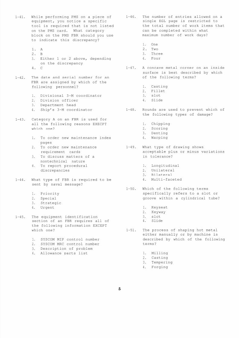
8/14/2019 US Navy Course NAVEDTRA 14115 - Gas Turbine Systems Technician Mechanical) 2
http://slidepdf.com/reader/full/us-navy-course-navedtra-14115-gas-turbine-systems-technician-mechanical 321/349
1-41. While performing PMS on a piece of
equipment, you notice a specific
tool is required that is not listed
on the PMS card. What category
block on the PMS FBR should you use
to indicate this discrepancy?
1. A
2. B
3. Either 1 or 2 above, dependingon the discrepancy
4. C
1-42. The date and serial number for an
FBR are assigned by which of the
following personnel?
1. Divisional 3-M coordinator
2. Division officer
3. Department head
4. Ship’s 3-M coordinator
1-43. Category A on an FBR is used for
all the following reasons EXECPT
which one?
1. To order new maintenance index
pages
2. To order new maintenance
requirement cards
3. To discuss matters of a
nontechnical nature
4. To report procedural
discrepancies
1-44. What type of FBR is required to be
sent by naval message?
1. Priority
2. Special
3. Strategic
4. Urgent
1-45. The equipment identificationsection of an FBR requires all of
the following information EXCEPT
which one?
1. SYSCOM MIP control number
2. SYSCOM MRC control number
3. Description of problem
4. Allowance parts list
1-46. The number of entries allowed on a
single EGL page is restricted to
the total number of work items that
can be completed within what
maximum number of work days?
1. One
2. Two
3. Three
4. Four
1-47. A concave metal corner on an inside
surface is best described by which
of the following terms?
1. Casting
2. Fillet
3. slot
4. Slide
1-48. Rounds are used to prevent which of
the following types of damage?
1. Chipping
2. Scoring
3. Denting
4. Warping
1-49. What type of drawing shows
acceptable plus or minus variations
in tolerance?
1. Longitudinal
2. Unilateral
3. Bilateral
4. Multi-faceted
1-50. Which of the following terms
specifically refers to a slot or
groove within a cylindrical tube?
1. Keyseat
2. Keyway
3. slot
4. Slide
1-51. The process of shaping hot metal
either manually or by machine is
described by which of the following
terms?
1. Milling
2. Casting
3. Tempering
4. Forging
5

8/14/2019 US Navy Course NAVEDTRA 14115 - Gas Turbine Systems Technician Mechanical) 2
http://slidepdf.com/reader/full/us-navy-course-navedtra-14115-gas-turbine-systems-technician-mechanical 322/349
1-52. What type of drawing method is used
when variations from the design
size are permissible in one
direction only?
1. Bilateral
2. Unilateral
3. Longitudinal
4. Multi-faceted
1-53. A drawing that provides a
two-dimensional view (height and
width) is which of the following
types?
1. Oblique
2. Orthographic
3. Isometric
4. Detail
1-54. A drawing that projects the front
and top of an object (height,width, and length) is which of the
following types?
1. Oblique
2. Orthographic
3. Isometric
4. Detail
1-55. A set of three or more views of an
object where all lines are shown in
their true length describes which
of the following drawings?
1. Oblique
2. Orthographic
3. Isometric
4. Detail
1-56. The flash point of a fuel is the
highest temperature at which the
fuel will give off sufficient vapor
to form a flammable mixture.
1. True
2. False
1-57. What is the minimum flash point for
naval distillates?
1. 135°F
2. 140°F
3. 145°F
4. 150°F
1-58. The general specifications for the
building of ships require suitable
insulation to be installed on any
surface that might exceed what
maximum temperature?
1. 200°F
2. 300°F
3. 400°F
4. 500°F
1-59. Because most chemicals are
hazardous by nature, what
information source should you
review before using a chemical?
1. MSDS
2. MSOS
3. MSIG
4. MSIB
1-60.The testing of oils is normallylimited to what two types of
chemicals?
1. Isopropyl alcohol and
dry-cleaning solvent
2. Dry-cleaning solvent and
absolute methanol
3. Absolute methanol and hydrogen
peroxide
4. Hydrogen peroxide and isopropyl
alcohol
1-61. Absolute methanol is considered tobe highly toxic if ingested.
1. True
2. False
1-62. When mixing water treatment
chemicals such as DSP or TSP, you
are cautioned against using hot
water for what main reason?
1. The chemicals will tend to cake
2. The chemicals will generate
heat that may exceed the safedispensing temperature
3. The chemicals will tend to foam
4. The chemicals will become
inactive
6

8/14/2019 US Navy Course NAVEDTRA 14115 - Gas Turbine Systems Technician Mechanical) 2
http://slidepdf.com/reader/full/us-navy-course-navedtra-14115-gas-turbine-systems-technician-mechanical 323/349
1-63. If alkalies come into contact with
your eyes, you should flush your
eyes for at least what period of
time?
1. 5 minutes
2. 10 minutes
3. 15 minutes
4. 20 minutes
1-64. Which of the following hazardous
compounds will likely be present in
the water test chemicals you must
use aboard ship?
1-65. You can find authorized procedures
for handling and disposing of
hazardous wastes in which of the
following OPNAV instructions?
1. OPNAVINST 5090.1A
2. OPNAVINST 51OO.23B
3. OPNAVINST 3540.1B
4. OPNAVINST 3540.12B
1. Caustic soda
2. Nitric acid
3. Mercuric nitrate
4. All of the above
7

8/14/2019 US Navy Course NAVEDTRA 14115 - Gas Turbine Systems Technician Mechanical) 2
http://slidepdf.com/reader/full/us-navy-course-navedtra-14115-gas-turbine-systems-technician-mechanical 324/349
ASSIGNMENT 2
Textbook Assignment: “Oil Laboratory Procedures and Administration,”
through 2-43.
chapter 2, pages 2-4
2-1.
2-2.
2-3.
2-4.
All oily discharges within 12 nm of
the U.S. coastline must not exceed
what maximum ppm of effluent?
1. 5 ppm
2. 10 ppm
3. 15 ppm
4. 20 ppm
If your ship does not have a waste
oil system dedicated to collecting
waste synthetic oil, the synthetic
oily waste must be stored in what
minimum size of steel container?
1. 5 gal2. 10 gal
3. 30 gal
4. 55 gal
All bottles containing mercury
wastes can be turned over for
disposal to all of the following
persons or facilities EXCEPT which
one?
1. Public works officer
2. Engineering officer
3. Public works center at a navalinstallation
4. Industrial facility
To perform a BS&W test, the
centrifuge you use must be capable
of holding (a) at least how many
pear-shaped tubes (b) of what
standard capacity (per tube)?
1. (a) Two; (b) 50 ml
2. (a) Two; (b) 100 ml
3. (a) Four; (b) 50 ml
4. (a) Four; (b) 100 ml
2-5. When testing F-76 fuels, you will
use the AEL MK III contaminated
fuel tester to perform how many ofthe required tests?
1. Five
2. Two
3. Three
4. Four
2-6. The flash point tester uses a
propane flame to heat the fuel
being tested.
1. True
2. False
2-7. As a minimum requirement, your ship
should have FO sample valve
connections at all of the following
locations EXCEPT which one?
1. Each sounding tube connection
2. Each purifier clean-fuel
discharge
3. Each coalescer fuel inlet
4. Each coalescer fuel outlet
2-8. Visual samples for F-76 fuel duringa refueling evolution must be taken
at what intervals?
1. Every 15 minutes
2. The beginning, middle, and end
3. Both 1 and 2 above
4. Every 40 minutes
2-9. When receiving F-76 fuel from a
U.S. government supply source, your
ship must perform which of the
following tests to satisfy the
minimum requirements for samplingand testing?
1. API gravity test
2. Flash point test
3. Visual samples only
4. Visual inspections and three
BS&W tests
8

8/14/2019 US Navy Course NAVEDTRA 14115 - Gas Turbine Systems Technician Mechanical) 2
http://slidepdf.com/reader/full/us-navy-course-navedtra-14115-gas-turbine-systems-technician-mechanical 325/349
2-10. When performing a BS&W test on F-76
fuel, the fuel sample must not be
below what minimum temperature?
1. 80°F
2. 70°F
3. 60°F
4. 50°F
2-11. Each time a FO sample is tested forBS&W, the sample must spin for what
specified amount of time”?
1. 5 minutes
2. 10 minutes
3. 15 minutes
4. 20 minutes
2-12. You must centrifuge a BS&W fuel
sample until you obtain the same
reading for what total number of
consecutive times?
1. Five
2. Two
3. Three
4. Four
2-13. To determine the total BS&W of a
fuel sample, you must always add
the readings of both tubes and then
divide by 2.
1. True
2. False
2-14. The API gravity conversion charts
for F-76 fuel can be found in what
chapter of the Naval Ships’
Technical Manual?
1. Chapter 233
2. Chapter 234
3. Chapter 541
4. Chapter 542
2-15. When performing a flash point test,
you should set the test flame to
what specified height?
1. 3/16 in.
2. 5/16 in.
3. 3/32 in.
4. 5/32 in.
2-16. During a flash point test, the rate
of temperature rise of the test
fuel should NOT exceed what maximum
amount?
1. ll°F
2. 10°F
3. 9°F
4. 8°F
2-17. During a flash point test, you
should lower the test flame into
the vapor space each time the fuel
sample temperature rises what
specified number of degrees?
1. 1°F
2. 2°F
3. 3°F
4.4°F
2-18. After receipt of fuel, a water
contamination test will beperformed on noncompensated FO
storage tanks after what specified
number of hours has elapsed?
1. 12 hours
2. 24 hours
3. 36 hours
4. 48 hours
2-19. During a service tank
replenishment, you must sample and
inspect the purifier discharge at
what specified intervals?
1. 5 minutes after the start of
transfer and every 15 minutes
thereafter
2. 5 minutes after the start of
transfer and every 30 minutes
thereafter
3. 15 minutes after the start of
transfer and every 15 minutes
thereafter
4. 15 minutes after the start of
transfer and every 30 minutes
thereafter
2-20. A properly working FO purifier can
remove up to what maximum amount of
contaminates in a single pass?
1. 50%
2. 60%3. 70%
4. 80%
9

8/14/2019 US Navy Course NAVEDTRA 14115 - Gas Turbine Systems Technician Mechanical) 2
http://slidepdf.com/reader/full/us-navy-course-navedtra-14115-gas-turbine-systems-technician-mechanical 326/349
2-21. Once a FO service tank is placed on
suction, you must sample and test
the coalscer discharge (a) within
what maximum number of minutes
after the tank is placed on suction
and (b) at what specified interval
thereafter?
1. (a) 15 min; (b) every 2 hr
2.(a) 15 min; (b) every 4 hr
3. (a) 5 min; (b) every 2 hr
4. (a) 5 min; (b) every 4 hr
2-22. When performing a fuel
contamination test on F-76, you
must fill the AEL Mk III tester’s
plastic sample bottle with test
fuel to what prescribed level?
1. 100 mL
2. 200 mL
3. 400 mL
4.800 mL
2-23. Before pumping an F-76 test sample
through the water detection pad,
you should shake the sample
vigorously for at least how many
seconds?
1. 10 seconds
2. 20 seconds
3. 30 seconds
4. 60 seconds
2-24. To be suitable for use, F-44 fuelscannot exceed what maximum amount
of solids contamination?
1. 2.00 mg/L
2. 2.64 mg/L
3. 5.00 ppm
4. 40.0 ppm
2-25. An FSII test requires what amount
of fuel to be poured into the
graduated cylinder?
1. 100 mL2. 120 mL
3. 140 mL
4. 160 mL
2-26. During an FSII test, after adding
water to the fuel, you must shake
the sample to allow the icing
inhibitor to leach into the water.
1. True
2. False
2-27. At a minimum, the LO on idle
equipment should be sampled at whatspecified interval?
1. Daily
2. Weekly
3. Biweekly
4. Monthly
2-28. An F-76 free water test result of
5 ppm or less by chart equates to
an actual limit of which of the
following amounts?
1.10 ppm or less
2. 20 ppm or less
3. 30 ppm or less
4. 40 ppm or less
2-29. What number of LO sampling methods
are commonly used aboard ship?
1. One
2. Two
3. Three
4. Four
2-30. Normal LO sampling for the MRG mustbe performed for all of the
following situations EXCEPT which
one?
1. Daily on operating equipment
2. Weekly on idle equipment
3. During casualty control drills
4. 30 minutes after equipment
start-up
2-31. A LO thief sampler is approximately
how many inches longer than the
sounding tape plumb bob?
1. 6 in.
2. 5 in.
3. 3 in.
4. 4 in.
10

8/14/2019 US Navy Course NAVEDTRA 14115 - Gas Turbine Systems Technician Mechanical) 2
http://slidepdf.com/reader/full/us-navy-course-navedtra-14115-gas-turbine-systems-technician-mechanical 327/349
2-32. Which of the following information
is NOT required on a properly
labeled LO sample?
1. Equipment name
2. Equipment sump level
3. Oil type
4. Date
2-33. To perform a visual inspection on a
LO sample, you should invert the
sample bottle (a) a minimum of how
many times, and allow the fuel
sample to settle (b) a minimum of
how many seconds between
inversions?
1. (a) Two; (b) 30 sec
2. (a) Two; (b) 60 sec
3. (a) Three; (b) 30 sec
4. (a) Three; (b) 60 sec
2-34. A LO sample you have taken from an
LPAC fails a visual test. Which of
the following actions should you
take next?
1. Change the oil
2. Change the oil filter
3. Perform a BS&W test
4. Perform a transparency test
2-35. To perform a BS&W test on a LO
sample, you should dilute the LO
with what solution?
1. Water-saturated, dry-cleaning
solvent
2. Isopropyl alcohol
3. Absolute methanol
4. Hydrogen peroxide
2-36. The results of a BS&W test on a LO
sample show that sediment is less
than 0.1% and combined BS&W is
0.3%. What is the actual status of
the LO?
1.Satisfactory
2. Warning
3. Controlled
4. Condemned
2-37. To perform a mineral oil
contamination test, you should use
what specified amount of synthetic
oil in your test sample?
1. 75 mL
2. 50 mL
3. 25 mL
4. 10 mL
2-38. A diesel LO acidity test must be
performed on an idle diesel at what
minimum periodicity?
1. Daily
2. Weekly
3. Biweekly
4. Monthly
2-39. When performing a diesel LO
dilution test, you must make
certain the temperature difference
between the new LO and the used LO
does not exceed what maximum
amount?
1. l°F
2. 2°F
3. 3°F
4. 4°F
2-40. Diesel LO must be changed when fuel
dilution reaches what maximum
percentage?
1. 0.2%
2. 0.5%
3. 2.0%
4. 5.0%
2-41. A water bath is used to raise the
temperature of a cloudy LO sample
to what specified amount?
1. 100°F
2. 11O°F
3. 120°F
4. 140°F
2-42. What is the primary contaminant of
shipboard water?
1. Rust
2. Silica
3. Sediment
4. Chloride
11

8/14/2019 US Navy Course NAVEDTRA 14115 - Gas Turbine Systems Technician Mechanical) 2
http://slidepdf.com/reader/full/us-navy-course-navedtra-14115-gas-turbine-systems-technician-mechanical 328/349
2-43. Water that results when used steam
is cooled is referred to by what
term?
1. Reserve feedwater
2. Deaerated feedwater
3. Condensate
4. Distillate
2-44. When samples are taken from a
steaming boiler, the time betweensamples should not exceed what
maximum number of hours?
1. 24 hours
2. 12 hours
3. 8 hours
4. 4 hours
2-45. A waste heat boiler water sample
must be taken for all of the
following situations EXCEPT which
one?
1. A minimum of every 8 hours when
operating
2. Prior to every start-up
3. Prior to a blowdown
4. 30 minutes after start-up
2-46. If a chemical chloride test result
is less than the salinity indicator
reading by more than 0.02 epm, what
action(s), if any, should you take
next?
1. Perform a hardness test
2. Perform another chloride test
3. Secure and dump the boiler
4. None
2-47. As indicated by the conductivity
indicator, the water draining from
the air ejector drains must not
exceed what specified conductivity
amount?
1. 1 JJ mho/cm
2. 5 p mho/cm3. 8 p mho/cm
4. 10 v mho/cm
2-48. Sodium nitrite used in Na/COO/2000
helps to form what type of
protective layer on ferrous metal
surfaces?
1. Alkaline
2. Borate
3. Oxide
4. Silicate
2-49. You can find authorized dieseljacket water test procedures in
which of the following NSTM
publications?
1. Chapter 220, Volume 2
2. Chapter 233
3. Chapter 234
4. Chapter 262
2-50. Whenever the waste heat system is
used to operate a distilling plant,
the waste heat water must be
sampled and tested for nitrite
levels at what minimum periodicity?
1. Every 8 hours
2. Every 12 hours
3. Every 24 hours
4. Every 48 hours
2-51. The addition of DSP to boiler water
should result in what change, if
any, to the (a) phosphates and (b)
alkalinity?
1. (a) Increase;
(b) slight increase
2. (a) No change;
(b) increase
3. (a) Decrease;
(b) no change
4. (a) Slight increase;
(b) decrease
2-52. In the testing of boiler water,
which of the following tests should
be accomplished first?
1. Alkalinity and phosphate
2. Conductivity
3. Chloride
4. Either 2 or 3 above, depending
on the availability of test
equipment
12

8/14/2019 US Navy Course NAVEDTRA 14115 - Gas Turbine Systems Technician Mechanical) 2
http://slidepdf.com/reader/full/us-navy-course-navedtra-14115-gas-turbine-systems-technician-mechanical 329/349
2-53. A common mistake when performing achloride test is to add reagents
too quickly while titrating.
1. True
2. False
2-54. When the continuous chemical
injection system is started, the
pump stroke should be at what
setting?
1. 40%
2. 50%
3. 60%
4. 70%
2-55. The continuous chemical injection
tank must be refilled when the
liquid level drops to what capacity
range?
1. Between 1 and 5 gallons
2.Between 5 and 10 gallons
3. Between 10 and 20 gallons
4. Between 20 and 25 gallons
2-56. What is the maximum amount of TSP
that can be injected into a boiler
at one time?
1. 200 grams
2. 300 grams
3. 400 grams
4. 500 grams
2-57. Which of the following symptomsdoes NOT describe chemical hideout?
1. A large chemical decrease when
the generator load decreases
2. A large chemical increase when
the generator load decreases
3. A large chemical decrease when
the generator load increases
4. A large chemical increase when
the generator is secured
2-58. When chemical hideout has been
confirmed, alkalinity and
phosphates must be maintained above
what minimum levels?
1. 25.0 epm alkalinity and 0.005
ppm phosphate
2. 2.50 epm alkalinity and 0.050
ppm phosphate
3. 0.25 epm alkalinity and 0.050
ppm phosphate
4. 0.025 epm alkalinity and 5.0
ppm phosphate
2-59. It boiler water samples contain
sediment, the maximum time between
blowdowns should not exceed how
many hours?
1. 48 hours
2. 24 hours
3. 12 hours
4. 8 hours
2-60. To allow the water to circulate and
the boiler to stabilize, you should
wait a minimum of how many seconds
between blowdown cycles?
1. 30 seconds
2. 45 seconds
3. 60 seconds
4. 90 seconds
2-61. With the feedwater system operating
properly, the makeup feedwater rate
should be less than what specifiedamount per day?
1. 500 gallons
2. 600 gallons
3. 900 gallons
4. 1,000 gallons
2-62. Dissolved oxygen contamination can
be caused by all of the following
mechanical failures EXCEPT which
one ?
1. Low water level in the DFT2. Improper operation of the DFT
spray nozzles
3. Inadequate venting of the DFT
4. A malfunctioning steam control
valve
13

8/14/2019 US Navy Course NAVEDTRA 14115 - Gas Turbine Systems Technician Mechanical) 2
http://slidepdf.com/reader/full/us-navy-course-navedtra-14115-gas-turbine-systems-technician-mechanical 330/349
2-63. Maintaining nitrite levels below
1,000 ppm is ideal for corrosion
control in a diesel jacket water
system.
1. True
2. False
2-64. Conversion charts supplied with
each quantab bottle can only be
used with the test strips from thatbottle.
2-65. The nitrite concentration level in
the waste heat system must not
exceed what maximum amount?
1. 5 ppm
2. 10 ppm
3. 20 ppm
4. 25 ppm
1. True
2. False
14

8/14/2019 US Navy Course NAVEDTRA 14115 - Gas Turbine Systems Technician Mechanical) 2
http://slidepdf.com/reader/full/us-navy-course-navedtra-14115-gas-turbine-systems-technician-mechanical 331/349
ASSIGNMENT 3
Textbook Assignment: “Engineering Control System Operation,” chapter 3, pages 3-1 through
3-30, and “Engineering Support and Auxiliary Equipment and Systems,”
chapter 4, pages 4-1 through 4-8.
3-1. Which of the following classes of
gas turbine-powered ships uses the
machinery control system (MCS) tocontrol and monitor its gas turbine
equipment?
1. DD-963
2. DDG-993
3. DDG-51
4. FFG-7
3-2. The ECSS is found on which of the
following classes of gas
turbine-powered ships?
1. DD-963,2. DD-963,
3. DDG-51,
4. DDG-51,
DDG-993, and FFG-7DDG-993, and CG-47
DDG-993, and CG-47
FFG-7, and CG-47
3-3. On gas turbine-powered ships, what
is the main operating station from
which the engineering plant is
controlled and monitored?
1.
2.
3.
4. AMR
3-4. On
MER
Pilothouse
CCS
the CG-47 class ships, what two
major engineering control consoles
are located in the CCS?
1. FSCC and PACC
2. FSCC and EPCC
3. EPCC and PCC
4. EPCC and PACC
3-5. On the DD-963 class ships, which of
the following FO service system
functions are available at the PACC?
1. FO transfer system control
2. FO service control and
monitoring
3. GTE FO control and monitoring
4. Both 2 and 3 above
3-6. On the DDG-993 class ships, which
the following fuel service functio
are available at the PACC and thePLCC simultaneously?
1. Monitoring
2. Control
3. Both 1 and 2 above
4. Defueling control
3-7. On the CG-47 class ships, which of
the following methods will cause t
GTE fuel purge valve to open?
1. Depressing the FUEL PURGE ON
push button at the PACC2. Depressing the FUEL PURGE ON
push button at the PLCC
3. Either 1 or 2 above, depending
on the operator
4. Automatic activation of the
start/stop sequence control
logic
3-8. On the DD-963 class ships, what ar
the two main air systems associate
with the GTEs and GTGSs?
1. Bleed air and ship’s service a2. Bleed air and HP air
3. Ship’s service air and HP air
4. Emergency air and HP air
3-9. On a DD-963 class ship, when the
start air mode on the PACC is in
NORMAL and the motor air regulator
valve is in the motoring position.
start air pressure is regulated to
what specific pressure?
1. 10 psig
2. 19 psig
3. 22 psig
4. 35 psig
15

8/14/2019 US Navy Course NAVEDTRA 14115 - Gas Turbine Systems Technician Mechanical) 2
http://slidepdf.com/reader/full/us-navy-course-navedtra-14115-gas-turbine-systems-technician-mechanical 332/349
3-10. On a DDG-993 class ship, all of the
following GTE start/stop modes are
available at the PACC EXCEPT which
one?
1. Manual
2. Manual initiate
3. Auto initiate
4. Supervisory control
3-11. What type of throttle and pitch
control system is used on a CG-47
class ship?
1. Analog
2. Digital
3. Discrete
4. Binary
3-12. On the CG-47 class ships, GTGS
sensor information is sent to the
EPCC in all of the following ways
EXCEPT which one?
1. Through the PAMISE via S/CE
No. 1
2. Directly from the alarm contact
switches
3. Through the alarm detector
circuits in the LOCOP
4. Through the alarm generator in
the PLCC
3-13. On the DD-963 class ships, which of
the following bus tie breakers have
Auto Trip commands?
1. 1S-2S and 1S-3S
2. 2S-1S and 2S-3S
3. 3S-1S and 3S-2S
4. 3S-1S and 2S-1S
3-14. On the EPCC of a DD-963 class ship,
the two modes of governor operation
are normal and what other mode?
1. Isochronous
2. Droop
3. Continuous speed4. Automatic
3-15. On the CG-47 class ships, the load
shed relay is activated by what
control power?
1. +5 V dc
2. -5 V dc
3. +28 V dc
4. -28 V dc
3-16. The TOPS prevents the loss of a GT
resulting from which of the
following abnormal conditions?
1. Overtemperature
2. Overspeed
3. Overload
4. Overvoltage
QUESTIONS 3-17 THROUGH 3-36 PERTAIN TO
DDG-51 CLASS SHIPS.
3-17. The propulsion fuel controls
available at the PACC are limited
all of the following primary
functions EXCEPT which one?
1. Fuel cooling
2. Fuel purging
3. Closing the module fuel inlet
valve
4. Opening the module fuel inlet
valve
3-18. The solenoid-operated module fuel
inlet valve assumes what position
when it is electrically(a) energized or (b) de-energized?
1. (a) Open; (b) open
2. (a) Open; (b) closed
3. (a) Closed; (b) closed
4. (a) Closed; (b) open
3-19. The bleed air valve for the SSGTG
can be controlled from which of th
following locations?
1. SSGTG LOCOP or EPCC
2. SSGTG LOCOP or PACC3. EPCC or PACC
4. EPCC or SCU
16

8/14/2019 US Navy Course NAVEDTRA 14115 - Gas Turbine Systems Technician Mechanical) 2
http://slidepdf.com/reader/full/us-navy-course-navedtra-14115-gas-turbine-systems-technician-mechanical 333/349
3-20. The engine fan control computer
program function automatically
operates the module cooling fan and
damper in response to all of the
following Inputs EXCEPT which one?
1. Cooling air outlet temperature
transducer
2. GTE start command
3. Halon release command
4. Compressor inlet temperature
3-21. What are the five possible engine
states for a GTE?
1. OFF LINE, MOTOR, ON LINE,
RUNNING, and SECURED
2. OFF, MOTOR, ON, ON LINE, and
COOLDOWN
3. OFF, MOTOR, ON, RUNNING, and
COOLDOWN
4. OFF, MOTOR, STANDBY, RUNNING,
and COOLDOWN
3-22. What total number of the nine
automatic GTE shutdowns can be
inhibited by placing battle overrideon?
1. Five
2. Seven
3. Eight
4. Nine
3-23. What is the basic method of
controlling a ship’s speed?
1. Manual control mode
2. Lockout manual control mode
3. Normal programmed control mode
4. Automatic control mode
3-24. The programmed control computer
program function of the MCS is
designed for which of the following
purposes?
1. Ship maneuverability
2. Fuel economy
3. Speed
4. Flexibility
3-25. Which of the following independent
auxiliary systems can be controlled
from the PACC?
1. Freshwater service
2. Ship’s service air
3. Air conditioning and chill wate
4. Seawater cooling
3-26. Which of the following equipment
features will allow the electric
plant to remain operable if the EPC
computer fails?
1. The DMS signal transfer
functions
2. The hardwired switch functions
3. The backup batteries
4. A reserve computer
3-27. Which of the following EPCC
functions will be lost when the EPC
computer fails?
1. Electric plant alarm detection
2. EPCC DMS communications
3. Display at the EPCC plasma
display unit
4. All of the above
3-28. The generator field excitation is
regulated by which of the following
components?
1. EXCOP
2. LOCOP
3. Switchboard
4. EPCC
3-29. At what specific gas turbine speed
does the LOCOP enable the EXCOP?
1. 2,200 rpm
2. 4,525 rpm
3. 8,455 rpm
4. 12,225 rpm
3-30. The EPCC automatically controls
circuit breakers as a part of the
standby generator start function.
1. True
2. False
17

8/14/2019 US Navy Course NAVEDTRA 14115 - Gas Turbine Systems Technician Mechanical) 2
http://slidepdf.com/reader/full/us-navy-course-navedtra-14115-gas-turbine-systems-technician-mechanical 334/349
3-31. The shore power breaker close
control and phase monitoring devices
are operated from what location?
1. Switchboard No. 1
2. Switchboard No. 2
3. Switchboard No. 3
4. EPCC
3-32. The output frequency of an SSGTG iscontrolled by an electronic governor
located in which of the following
components?
1. EXCOP
2. LOCOP
3. EPCC
4. Switchboard
3-33. All of the following circuit
breakers opened during a load shed
operation must be closed locally
EXCEPT which ones?
1. Ventilation
2. Anti-icing heaters
3. Air-conditioning plants
4. Engine room nonvital panels
3-34. The bell log printer is a part of
what MCS console?
1. EPCC
2. PACC
3. SCU
4. EOOW/LU
3-35. Which of the following signal data
recorder-reproducer set tape drive
units is the Write Only drive?
1. Drive 1
2. Drive 2
3. Drive 3
4. Drive O
3-36. In the acronym AN/UYK-44(V), what
does the letter Y indicate?
1. Computing
2. Data processing
3. General utility
4. Army/Navy
3-37. Which of the following consoles is
specifically used to control and
monitor the auxiliary subsystems?
1. ACC
2. DCC
3. EPCC
4. PCC
3-38. The two modes of operation for theFO service pumps are manual and wh
other mode?
1. LEAD
2. AUTO SPEED ADVANCE
3. LEAD SPEED ADVANCE
4. AUTO LEAD
3-39. The gas turbine emergency supply
valve fails to what position upon
loss of electrical power?
1. Open2. Closed
3. Diverted
4. Regulated
3-40. The LO coastdown pumps are driven
which of the following components?
1. Electric motor
2. Hydraulic actuator
3. Air motor
4. Piston actuator
3-41. The MRG contains a total of how ma
(a) gearbox bearings and (b) line
shaft bearings?
1. (a) 1; (b) 28
2. (a) 1; (b) 29
3. (a) 28; (b) 1
4. (a) 29; (b) 1
3-42. Which of the following GTE control
modes are available on FFG-7 class
ships?
1. OFF LINE, MANUAL, and MANUAL
INITIATE
2. OFF LINE, MANUAL, and AUTOMATI
3. MOTOR, MANUAL, and AUTOMATIC
4. MOTOR, MANUAL INITIATE, and
AUTOMATIC
QUESTIONS 3-37 THROUGH 3-48 PERTAIN TO
FFG-7 CLASS SHIPS.
18

8/14/2019 US Navy Course NAVEDTRA 14115 - Gas Turbine Systems Technician Mechanical) 2
http://slidepdf.com/reader/full/us-navy-course-navedtra-14115-gas-turbine-systems-technician-mechanical 335/349
3-43. A normal stop on a GTE can be
initiated by the PCC operator in
either the programmed control mode
or the manual control mode.
1. True
2. False
3-44. The stator temperature meter on the
EPCC is graduated in what type of
degree measurement units?
1. Fahrenheit
2. Centimeters
3. Centigrade
4. Rankine
3-45. With the governor mode in droop,
within what specific percentage
range of bus frequency will the
generator frequency vary as the load
changes?
1. 0% to 6%
2. 7% to 10%
3. 11% to 17%
4. 18% to 25%
3-46. An alarm will be indicated on the
EPCC when the SSDG’s fuel service
tank level drops below what specific
percentage of tank capacity?
1. 20%
2. 25%
3. 30%4. 40%
3-47. The ACC interfaces with the data
processor in which of the following
consoles?
1. SCC
2. DCC
3. EPCC
4. PCC
3-48. Detailed information on the casualty
control procedures used in the CCScan be found in which of the
following manuals?
1. EOP
2. EOCC
3. ECSS
4. PMS
3-49.
3-50.
3-51.
3-52.
3-53.
3-54.
The helical-screw type of LPAC
installed on a CG-47 has what CFM
rating?
1. 50 cfm
2. 100 cfm
3. 150 cfm
4. 200 cfm
On ships with three LPACs, during
normal operations the cutoutpressure switches should be set at
what prescribed pressures?
1. 150 psig, 145 psig, 140 psig
2. 145 psig, 140 psig, 135 psig
3. 140 psig, 135 psig, 130 psig
4. 125 psig, 120 psig, 115 psig
An LPAC fails to start. All of th
following malfunctions could be th
cause EXCEPT which one?
1. A previous automatic safety
shutdown
2. A blown fuse
3. The air receiver pressure is
above the falling pressure set
point
4. The power switch is tripped
When a screw-type LPAC starts and
runs in the wrong direction, it wi
automatically stop between 5 to 12
seconds.
1. True
2. False
Loose drive belts on a
reciprocating-type LPAC will NOT
cause an abnormal noise during
operation.
1. True
2. False
Most automatic temperature control
valves used for cooling fail towhich of the following positions?
1. Closed
2. Open
3. Off
19

8/14/2019 US Navy Course NAVEDTRA 14115 - Gas Turbine Systems Technician Mechanical) 2
http://slidepdf.com/reader/full/us-navy-course-navedtra-14115-gas-turbine-systems-technician-mechanical 336/349
3-55. The steam diverting valve installed
in a WHB system uses what device, if
any, for manual operation?
1. A pneumatic override
2. A special wrench
3. A handwheel
4. None
3-56. The types and sizes of valves used
in any system are determined by the
needs of the system.
1. True
2. False
3-57. Valve operator mechanical linkages
are used for which of the following
purposes?
1. To reach valves installed in the
overhead
2. To reach valves installed in the
bilges
3. To reach valves installed in an
adjoining space
4. All of the above
3-58. Extensive damage may occur to a
solenoid-operated valve if it is not
exercised periodically according to
the standards in which of the
following NSTM chapters?
1. Chapter 504
2. Chapter 5053. Chapter 551
4. Chapter 555
3-59. To ensure proper operation, solenoid
valves should be cycled at what
minimum frequency?
1. Once a day
2. Once a week
3. Once every two weeks
4. Once a month
3-60. Most diaphragm control valve
actuators require what minimum
amount of air pressure to start
valve stem movement?
1. 1 psi
2. 2 psi
3. 5 psi
4. 10 psi
3-61. The use of a hot plate provides the
most efficient means to regulate
temperature during calibration of a
temperature control device.
1. True
2. False
3-62. What two basic types of LO pressure
regulating valves are used on gas
turbine-powered ships?
1. Pilot and bellows-operated
2. Pneumatic and self-contained
3. Solenoid-operated and
needle-type
4. Manual and operator-controlled
3-63. Self-contained pressure regulating
valves have which of the following
modes of operation?
1. Manual only
2. Automatic only
3. Manual and automatic
4. Bypass
3-64. You are testing automatic operation
of a self-contained pressure
regulating valve. It should
modulate and maintain the set
pressure within what specified
range?
1. 1 to 2 psi
2. 2 to 3 psi
3. 3 to 4 psi
4. 0 to 1 psi
20

8/14/2019 US Navy Course NAVEDTRA 14115 - Gas Turbine Systems Technician Mechanical) 2
http://slidepdf.com/reader/full/us-navy-course-navedtra-14115-gas-turbine-systems-technician-mechanical 337/349
ASSIGNMENT 4
Textbook Assignment: “Engineering Support and Auxiliary Equipment and Systems,” chapter 4,
pages 4-11 through 4-24; “Propulsion Plant Systems and Drive Train
Equipment,” chapter 5, pages 5-1 through 5-25; and “LCAC and PHM
Propulsion Systems,” chapter 6, pages 6-1 through 6-47.
4-1.
4-2.
4-3.
4-4.
4-5.
The ship’s service LP air system is
divided into what total number of
basic subsystems?
1. Six
2. Two
3. Three
4. Four
Which of the following LP air
subsystems provides air to the
sonar dome?
1. MER vital air system
2. Ship’s vital air system
3. Electronic dry air system
4. MER nonvital air system
On a DDG-51 class ship, an HP/LP
air reducing station is located in
which of the following areas?
1. AMR1
2. MER1
3. MER 2
4. Both 2 and 3 above
The bleed air collection and
distribution system supports
total number of subsystems?
1. One
2. Two
3. Three
4. Four
The bleed air collection and
what
distribution system is regulated to
what specified pressure?
1. 100 psi
2. 80 psi
3. 75 psi
4. 65 psi
4-6. What is the only gas turbine-class
ship that does not have HP air
starting capabilities for thepropulsion GTEs?
1. DDG-51
2. DDG-993
3. GG-47
4. DD-963
4-7. The GTM start air system on
DD-963 class ship mixes hot
air and cool masker air for
of the following reasons?
bleed
which
1.
2.
3.
4.
The increase in air temperature
allows the propulsion turbine
end GTE starters to consume a
lower amount of air
The decrease in air temperature
causes the propulsion turbine
and GTE starters to use a
greater amount of air
The increase in air temperature
allows for HP start air
capabilities
The decrease in air temperature
allows for HP start air
capabilities
4-8. The start air system on a CG-47
class ship has what three modes of
operation?
1. Normal, motor, and automatic
2. Motor, automatic, and emergency
3. Normal, motor, and emergency
4. Normal, automatic, and
emergency
21
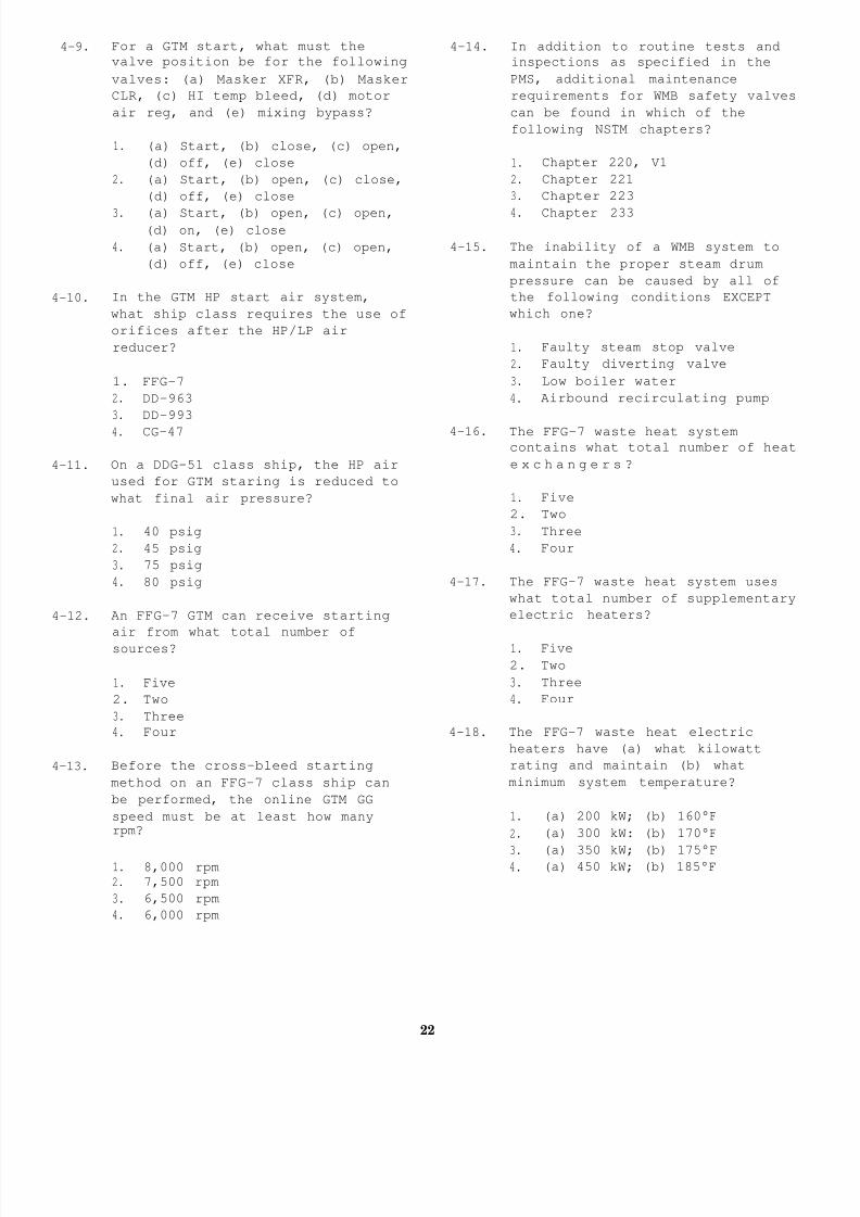
8/14/2019 US Navy Course NAVEDTRA 14115 - Gas Turbine Systems Technician Mechanical) 2
http://slidepdf.com/reader/full/us-navy-course-navedtra-14115-gas-turbine-systems-technician-mechanical 338/349
4-9. For a GTM start, what must the
valve position be for the following
valves: (a) Masker XFR, (b) Masker
CLR, (c) HI temp bleed, (d) motor
air reg, and (e) mixing bypass?
1. (a) Start, (b) close, (c) open,
(d) off, (e) close
2. (a) Start, (b) open, (c) close,
(d) off, (e) close
3. (a) Start, (b) open, (c) open,(d) on, (e) close
4. (a) Start, (b) open, (c) open,
(d) off, (e) close
4-10. In the GTM HP start air system,
what ship class requires the use of
orifices after the HP/LP air
reducer?
1. FFG-7
2. DD-963
3. DD-993
4. CG-47
4-11. On a DDG-51 class ship, the HP air
used for GTM staring is reduced to
what final air pressure?
1. 40 psig
2. 45 psig
3. 75 psig
4. 80 psig
4-12. An FFG-7 GTM can receive starting
air from what total number of
sources?
1. Five
2. Two
3. Three
4. Four
4-13. Before the cross-bleed starting
method on an FFG-7 class ship can
be performed, the online GTM GG
speed must be at least how manyrpm?
1. 8,000 rpm
2. 7,500 rpm
3. 6,500 rpm
4. 6,000 rpm
4-14. In addition to routine tests and
inspections as specified in the
PMS, additional maintenance
requirements for WMB safety valves
can be found in which of the
following NSTM chapters?
1. Chapter 220, V1
2. Chapter 221
3. Chapter 223
4. Chapter 233
4-15. The inability of a WMB system to
maintain the proper steam drum
pressure can be caused by all of
the following conditions EXCEPT
which one?
1. Faulty steam stop valve
2. Faulty diverting valve
3. Low boiler water
4. Airbound recirculating pump
4-16. The FFG-7 waste heat system
contains what total number of heat
e x c h a n g e r s ?
1. Five
2. Two
3. Three
4. Four
4-17. The FFG-7 waste heat system uses
what total number of supplementary
electric heaters?
1. Five
2. Two
3. Three
4. Four
4-18. The FFG-7 waste heat electric
heaters have (a) what kilowatt
rating and maintain (b) what
minimum system temperature?
1. (a) 200 kW; (b) 160°F
2. (a) 300 kW: (b) 170°F
3. (a) 350 kW; (b) 175°F4. (a) 450 kW; (b) 185°F
22

8/14/2019 US Navy Course NAVEDTRA 14115 - Gas Turbine Systems Technician Mechanical) 2
http://slidepdf.com/reader/full/us-navy-course-navedtra-14115-gas-turbine-systems-technician-mechanical 339/349
4-19. What total number of relief valves
are installed in the FFG-7 waste
heat system?
1. Five
2. Two
3. Three
4. Four
4-20. All preventive maintenance actions
or steps can be grouped into which
of the following three basiccategories?
1. Troubleshooting, routine
maintenance, and repair
2. Testing, adjusting, and
troubleshooting
3. Routine maintenance, testing.
and adjusting
4. Adjusting, testing, and repair
4-21. Using authorized maintenance
procedures and performing
maintenance at specified intervalsare included in what type of
maintenance actions?
1. Casualty
2. Routine
3. Emergent
4. Deferred
4-22. Which of the following corrective
maintenance actions is considered
to be the weakest link in the
corrective maintenance process?
1. Repair
2. Malfunction location
3. Testing
4. Symptom recognition
4-23. In the area of troubleshooting, the
amount of equipment downtime is
generally proportional to all of
the following conditions EXCEPT
which one?
4-24. The most important tool you can use
in troubleshooting is to have a
thorough knowledge of an equipment
or system’s normal operating
condition.
1. True
2. False
4-25. While performing a FO pump logic
test, you discover that pump timing
is off. Which of the followingactions should you take to correct
this problem?
1. Adjust the timing circuit card
2. Replace the pressure transducer
3. Repair the pressure switch
4. Replace the timing circuit card
4-26. Most FO service system low pressure
problems can be traced to which of
the following sources?
1. Faulty instruments2. Faulty unloader valves
3. Faulty pressure relief valves
4. Both 2 and 3 above
4-27. The MRG system LO pressure Is
regulated to the proper pressure as
sensed at which of the following
locations?
1. The LO pump discharge
2. The LO unloader valve inlet
3. The MRG most remote bearing
4. The MRG inlet header
4-28. Requirements for the operation and
care of the MRG LO strainer can be
found in which of the following
NSTM chapters?
1. Chapter 262
2. Chapter 244
3. Chapter 234
4. Chapter 233
1. Parts availability
2. System complexity
3. Poor methodology
4. Lack of system knowledge
23

8/14/2019 US Navy Course NAVEDTRA 14115 - Gas Turbine Systems Technician Mechanical) 2
http://slidepdf.com/reader/full/us-navy-course-navedtra-14115-gas-turbine-systems-technician-mechanical 340/349
4-29. On DD-963 class ships, the MRG LO
strainers should be shifted and
inspected once per watch for all of
the following conditions EXCEPT
which one?
1. For the first 48 hours
following MRG repairs
2. During normal operations
3. When the propulsion plant is
operating at more than 85% full
power
4. For the first 24 hours after
rough weather
4-30. The aligning of an attached LO pump
on CG-47 ships requires which, if
any, of the following components or
tools?
1. A special set of feeler gauges
2. A special dial indicator
3. A special shaft assembly
4. None of the above
4-31. All twin-screw, gas turbine-powered
ships have identical CRP/CPP
systems.
1. True
2. False
QUESTIONS 4-32 THROUGH 4-35 PERTAIN TO
CRP/CPP SYSTEMS INSTALLED ON THE DDG-51
CLASS SHIPS.
4-32. The electronic pitch position
transducer is located in which of
the following areas?
1. In the CRP electronics
enclosure
2. On the right side of the OD box
3. On the front end of the OD box
4. In the propeller hub
4-33. The CRP/CPP stationary electronics
cabinet sends an excitation signal
of what value to the rotarytransformer?
1. 4 kHz
2. 8 kHZ
3. 10 kHz
4. 12 kHz
4-34.
4-35.
4-36.
4-37.
4-38.
The temperature-compensated pitch
indicating system depends on the
thermal stability of which of the
following transmitting mediums to
sense pitch position?
1. Seawater
2. Prairie air
3. Masker air
4. CRP oil
The CRP rotating electronics
rectifies the rotary transformer
excitation to which of the
following power levels?
1. 12 V dc
2. -12 V dc
3. 24 V dc
4. -24 V dc
A steady increase in hub servo
pressure, without a change in
system demands, is a good
indication that which of the
following components is faulty?
1. Auxiliary relief valve
2. Sequencing valve (closed
position)
3. Reducing valve
4. Electrohydraulic servo valve
Which of the following components
supplies control oil to the OD box?
1. Reducing valve
2. Sequencing valve
3. Main servo piston
4. Auxiliary servo piston
When an MRG is opened for
inspection or repair, the persons
assigned to the security watch must
be in what minimum paygrade or
above?
1. E-3
2. E-43. E-5
4. E-6
24

8/14/2019 US Navy Course NAVEDTRA 14115 - Gas Turbine Systems Technician Mechanical) 2
http://slidepdf.com/reader/full/us-navy-course-navedtra-14115-gas-turbine-systems-technician-mechanical 341/349
4-39. Some MRG inspection requirements
and troubleshooting guides can be
found in which of the following
NSTM chapters?
1. Chapter 9340
2. Chapter 9420
3. Chapter 9430
4. Chapter 9880
4-40. An indication of reduced oil flow
in an MRG sight flow indicator can
result from all of the following
problems EXCEPT which one?
1. Air leakage around the base or
glass of the sight flow
indicator
2. A partially unseated sight flow
indicator oil supply tube
3. A small hole in the sight flow
indicator oil supply tube
4. Dirt accumulation in the
bearing oil passage
4-41. Even if oil flow is missing from
only one sight flow indicator, the
condition must be treated as if a
loss of LO has occurred to the
entire MRG.
1. True
2. False
4-42. Which of the following symptoms can
indicate a faulty pump angle drive
assembly?
1. High failure rate of the
attached pump flexible coupling
2. Difficulty in disengaging
3. Both 1 and 2 above
4. Failure of the electrical motor
4-43. An SSS clutch system requires which
of the following inputs or
conditions to make engagement
possible?
1. LP air
2. HP air
3. Electronic signals
4. PT input shaft speed greater
than that of the first
reduction pinion
4-44. In the SSS clutch systems installed
on Navy gas turbine ships, a total
of how many different types of PT
brake systems are used?
1. Six
2. Two
3. Three
4. Four
4-45. The shaft brake assembly installed
on an FFG-7 class ship is what
type?
1. Internally housed, friction
pack assembly
2. Externally mounted, friction
pack assembly
3. Internally housed, single-disc
caliper assembly
4. Externally mounted, single-disc
caliper assembly
4-46. Propulsion shaft bulkhead seals
perform which of the following
functions?
1. Maintain propulsion shaft axial
alignment
2. Maintain propulsion shaft
radial alignment
3. Both 1 and 2 above
4. Maintain watertight integrity
between machinery spaces
4-47. A line shaft bearing sump should be
drained and opened for all of the
following reasons or conditions
EXCEPT which one?
1. Bearing wear measurements ,
(depth readings) must be taken
2. The oil becomes contaminated
and must be changed
3. A bearing temperature sensor
needs to be replaced
4. Excessive leakage from bearing
oil seals is observed
4-48. Propulsion shaft alignment will be
affected under all of the following
circumstances EXCEPT which one?
1. Placing the ship in drydock
2. The removal of the ship’s
propeller or propellers
3. A faulty bulkhead seal
4. Damage to a line shaft bearing
25

8/14/2019 US Navy Course NAVEDTRA 14115 - Gas Turbine Systems Technician Mechanical) 2
http://slidepdf.com/reader/full/us-navy-course-navedtra-14115-gas-turbine-systems-technician-mechanical 342/349
4-49. A line shaft bearing contains what
total number of sealing rings?
1. One
2. Two
3. Three
4. Four
4-50. Bulkhead sealing rings are made of
such durable material that no
lubrication will ever be required.
1. True
2. False
4-51. The LCAC is powered by which of the
following types of GTEs?
1. LM2500
2. AVCO Lycoming TF40B
3. Allison 501-K34
4. Pratt Whitney 1500TB
4-52. On the LCAC, which of the following
personnel is of the GS rating?
1. Craft engineer/assistant
operator
2. Load master
3. Deck hand/engineer
4. Navigator
4-53. Rudder pedal movement on the LCAC
is converted into an electrical
signal that controls which of the
following components?
1. Pneumatic position piston
2. Electric motor positioner
3. Hydraulic position actuator
4. Steam actuator positioner
4-54. Which of the following components
of the LCAC steering control system
controls and sends signals to
various electrical components?
1. Rudder position drive assembly
2. Rudder channel selector3. CSEP
4. Pedal control
4-55. Each propeller pitch control lever
on the LCAC has a detent stop at
what specific degree of pitch?
1. 0
2. +15
3. -30
4. +40
4-56. The LCAC lift fan control system
consists of which of the following
components?
1. Two single-entry centrifugal
fans only
2. Two double-entry centrifugal
fans only
3. Four single-entry centrifugal
fans
4. Four double-entry centrifugal
fans
4-57. On the LCAC, what maximumpercentage of air produced by the
lift fan control system goes to the
(a) bow thrusters and (b) cushion?
1. (a) 60%; (b) 40%
2. (a) 70%; (b) 30%
3. (a) 30%; (b) 70%
4. (a) 40%; (b) 60%
4-58. In the engine control system on the
LCAC, which of the following units
is the power producer control unit?
1.N
1
2. N2
3. N3
4. N4
4-59. The power turbine section of the
TF40B GTE consists of what total
number of stages?
1. Eight
2. Two
3. Six
4. Four
26
8/14/2019 US Navy Course NAVEDTRA 14115 - Gas Turbine Systems Technician Mechanical) 2
http://slidepdf.com/reader/full/us-navy-course-navedtra-14115-gas-turbine-systems-technician-mechanical 343/349
4-60. On the LCAC, the automatic
shutdown, normal override switch
inhibits all automatic shutdowns of
the TF40B GTE EXCEPT which one?
1. Undertemperature
2. Overtemperature
3. Overspeed
4. Underspeed
4-61. What section of the C&C keyboard
contains the switches that control
the main engine coalescer drains?
1. FUEL/DEFUEL section
2. MISC section
3. APU FEED section
4. ENGINE FEED section
4-62. Which of the following categories
is NOT a maintenance repair level
for the LCAC?
1. Depot
2. Routine repair facility
3. Organizational
4. Specialized repair facility
4-63. The mission of the PHM is described
in all of the following statements
EXCEPT which one?
1. To screen amphibious forces in
the arrival and departure area
2. To conduct surveillance
3. To operate offensively against
hostile surface combatants
4.To provide low-speedair-cushion transport
capability
4-64. The PHM has what total number of
complete but separate propulsion
systems?
1. One
2. Two
3. Three
4. Four
4-65. Foilborne propulsion on the PHM isprovided by which of the following
components?
1. A single-stage water jet pump
powered by a diesel engine
2. A single-stage water jet pump
powered by a GTE
3. A 2-stage water jet pump
powered by a diesel engine
4. A 2-stage water jet pump
powered by a GTE
27

8/14/2019 US Navy Course NAVEDTRA 14115 - Gas Turbine Systems Technician Mechanical) 2
http://slidepdf.com/reader/full/us-navy-course-navedtra-14115-gas-turbine-systems-technician-mechanical 344/349
ASSIGNMENT 5
Textbook Assignment: “LCAC and PHM
and “Electric
Propulsion Systems,” chapter 6, pages 6-27 through 6-4
Plant,” chapter 7, pages 7-1 through 7-61.
5-1.
5-2.
5-3.
5-4.
5-5.
On gas turbine-powered ships, what
is the most widely used generator
prime mover?
1.
2.
3.
4.
On
Sunstrand T-62T-40-7
Garrett ME 831-800A
Allison 501-K17
Allison 501-K34
the DDG-51 class ships, the GTG
foundation and enclosure were made
larger for which of the following
reasons?
1. The turbine is larger
2. The generator is larger
3. To provide more space for
maintenance
4. To provide more space for
internal and external equipment
additions
The Allison 501-K34 GTE uses which
of the following major components
to replace the GCU used with the
501-K17 GTE?
1. PCM
2. EXCOP
3. IFM
4. FDM
On a 501-K34, PMA power is routed
to various modules by what
component?
1. DFD
2. OVL
3. AVR
4. PCM
To regulate GTE fuel flow on a
501-K34, the electronic governor
uses all of the following input
signals EXCEPT which one?
1. Calculated turbine inlet
temperature
2. Compressor discharge pressure
3. Generator voltage
4. Generator current
5-6. The 501-K34 start air piping was
modified to accommodate which of
the following components?
1. The band pump
2. The turbine prelube pump
3. The EXCOP
4. The LOCOP
5-7. On a PHM operating at 100 percent
power, the GTE delivers what
maximum (a) horsepower to the
gearbox assembly and at what
approximate (b) input speed?
1. (a) 16,767 hp; (b) 3,100 rpm2. (a) 15,541 hp; (b) 2,900 rpm
3. (a) 13,821 hp; (b) 2,500 rpm
4. (a) 12,780 hp; (b) 2,100 rpm
5-8. In the PHM, the gas turbine
electronics that interface with the
propulsion control system are
contained in what component?
1. FSEE
2. EOP
3. BMEE
4. FBCP
5-9. What system of the PHM provides
automatic starting and stopping of
the GTE and gearbox auxiliary LO
pump?
1. FECS
2. FPCS
3. HECS
4. HPCS
5-10. The gearbox assembly in the powertrain subsystem of the PHM consists
of what type of reduction gear?
1. Single helical
2. Double helical
3. Single herringbone
4. Double herringbone
28
8/14/2019 US Navy Course NAVEDTRA 14115 - Gas Turbine Systems Technician Mechanical) 2
http://slidepdf.com/reader/full/us-navy-course-navedtra-14115-gas-turbine-systems-technician-mechanical 345/349
5-11. What total number of thermocouples
is located in the power train
subsystem gearbox assembly of thePHM?
1. Eight
2. Two
3. Six
4. Four
5-12. In the PHM, the GTE is directly
coupled to the propulsor through
the gearbox with no disengagement
capabilities.
1. True
2. False
5-13. The FBCS provides dynamic control
of the PHM by sensing which of the
following ship motions?
1. Vertical acceleration
2. Yaw rate
3. Roll
4. All of the above
5-14. What is the input power to the ACS
power supply assembly of the PHH?
1. 115 V ac, 60 HZ
2. 115 V ac, 400 Hz
3. 450 V ac, 60 Hz
4. 450 V ac, 400 Hz
5-15. On the PHM, the GTE is located inwhat area?
1. AMR No. 1
2. MER No. 2
3. Gas turbine machinery room
4. Propulsion gear room
5-16. Each hullborne power plant on a PHM
consists of a diesel engine and
which of the following components?
1. Propulsor assembly and water
brake2. Water jet pump and speed
reduction gearbox
3. Water jet pump and water brake
4. Speed reduction gearbox and
5-17. The hullborne power plants can
propel the PHM up to what maximum
speed?
1. 5 knots
2. 11 knots
3. 22 knots
4. 40 knots
5-18. The hullborne propulsion system of
the PHM consists of a total of how
many diesel engines?
1. One
2. Two
3. Three
4. Four
5-19. On the PHM, what is the purpose of
the bow thruster?
1. To provide improved low-speed
maneuverability
2. To assist in docking
3. Both 1 and 2 above
4. To provide lift power to the
forward strut
5-20. On the PHM, basic control of the
electrical generators is provided
at what station?
1. EOS
2. CCS
3. EPCC
4. Pilothouse
5-21. Emergency electrical power on the
PHM is provided by what source?
1. An emergency ac generator
2. Two diesel engine alternators
3. Three battery sets
4. Either 2 or 3 above, depending
on the source selected
5-22. What type of compressor is used in
the SSPUs on the PHM?
1. Single-stage, axial-flow
2. Two-stage, axial-flow
3. Single-stage, centrifugal-flow
4. Two-stage, centrifugal-flow
water brake
29

8/14/2019 US Navy Course NAVEDTRA 14115 - Gas Turbine Systems Technician Mechanical) 2
http://slidepdf.com/reader/full/us-navy-course-navedtra-14115-gas-turbine-systems-technician-mechanical 346/349
5-23. During the start of an SSPU, at
what percentage of engine speed
does the ignition system
automatically de-energize?
1. 10%
2. 50%
3. 95%
4. 100%
5-24. When the power section of the PHM
SSPU is operating at 100 percent,
what is its maximum speed?
1. 39,476 rpm
2. 41,730 rpm
3. 45,822 rpm
4. 49,630 rpm
5-25. With the power section of the PHM
SSPU operating at 100 percent
speed, the load compressor is
running at what specific speed?
1. 3,600 rpm
2. 4,500 rpm
3. 8,000 rpm
4. 12,800 rpm
5-26. On the PHM, the SSPU lubricating
system is what type?
1. Full-pressure, wet-sump
2. Full-pressure, dry-sump
3. Forced-fed, dry-sump
4. Forced-fed, open-sump
5-27. In the PHM, what is the capacity of
the oil sump for each SSPU?
1. 7.8 quarts
2. 7.4 quarts
3. 7.8 gallons
4. 7.4 gallons
5-28. What minimum percent of SSPU speed
will cause an overspeed trip?
1. 105%
2. 108%
3. 110%
4. 115%
5-29. The SSPU load and speed control
unit requires what specific level
of power to operate?
1. 11O-V ac
2. 11O-V dc
3. 24-V ac
4. 24-V dc
5-30. During steady-state speed, the oilpressure regulator maintains what
minimum SSPU oil pressure?
1. 60 psi
2. 70 psi
3. 80 pSi
4. 90 psi
5-31. In the PHM, the filter assemblies
located on the side of the SSPU
meter panel serve what function?
1. To smooth out the pulsating dc
provided by the rectifier
2. To filter out dirt and dust
3. To filter the feedback signal
from the SSPU
4. To filter the EM1 generated by
the exhaust gas temperature
meter transducers
5-32. Which of the following best
describes the ac generators on thePHM?
1. Brushless, 250-kVA, 450-V ac,
400-Hz, 3-phase
2. Brushless, 250-kVA, 450-V ac,
60-Hz, 3-phase
3. Brushless, 250-kVA, 450-V ac,
400-Hz, single-phase
4. Brushless, 250-kVA, 450-V ac,
60-Hz, single-phase
5-33. Initial excitation of the ac
generator on the PHM is provided by
which of the following components?
1. An external PMA
2. A 3-phase alternator
3. An internal single-phase
generator
4. An internal 3-phase generator
30
8/14/2019 US Navy Course NAVEDTRA 14115 - Gas Turbine Systems Technician Mechanical) 2
http://slidepdf.com/reader/full/us-navy-course-navedtra-14115-gas-turbine-systems-technician-mechanical 347/349
5-34. On the PHM, where is the GCU
located?
1. Adjacent to each switchboard
2. Adjacent to each generator
3. Inside each switchboard
4. Inside each generator
5-35. The generators on the PHM can be
operated in all of the followingmodes EXCEPT which one?
1. Individual
2. Series
3. split-plant
4. Parallel
5-36. The shore power receptacles on the
PHM are rated for the shore power
electrical load of the ship plus
what percent growth margin?
1. 10%2. 20%
3. 30%
4. 40%
5-37. Before the shore power monitor will
allow power to be applied to the
PHM, all of the following
conditions must be met EXCEPT which
one ?
1. AB, BC, or CA phase rotation
2. 410 V ac to 471 V ac
3. 365 Hz to 435 Hz4. 57 HZ to 63 HZ
5-38. Which of the following best
describes the motor generator of
the mobile electric power unit used
to provide shore power to the PHM?
1. Two-bearing, salient-pole,
brushless
2. Two-bearing, squirrel-cage,
brushless
3. Single-bearing, salient-pole,
brushless
4. Single-bearing, squirrel-cage,
brushless
5-39. The mobile electric power unit used
to provide the PHM with shore power
operates from what power source?
1. 450-V ac, 3-phase, 400-Hz
2. 450-V ac, 3-phase, 60-Hz
3. 480-V ac, 3-phase, 400-Hz
4. 480-V ac, 3-phase, 60-HZ
5-40. The PHM fuel system delivers whattypes of fuels to the diesels,
GTEs, and SSPUS?
1. JP-5 and DFM
2. DFM and MOGAS
3. MOGAS and JP-5
4. Gasoline and MOGAS
5-41. The fuel purifier on the PHM can
process a maximum of how many
gallons of fuel per minute?
1. 15 gal/min2. 25 gal/min
3. 35 gal/min
40
45 gal/min
5-42. On the PHM, what is the primary
source of compressed air?
1. A compressed air system air
compressor
2. SSPU 2nd-stage bleed air
3. An HP air compressor
4. LM2500 16th-stage bleed air
5-43. The primary source of compressed
air is cooled to what temperature
before it is used?
1. 86°F
2. 75°F
3. 60°F
4. 54°F
5-44. The seawater system on the PHM
serves all of the following
purposes EXCEPT which one?
1. Combating fires
2. Machinery cooling
3. Propulsor bearing lubricating
4. Turbine aft bearing cooling
31

8/14/2019 US Navy Course NAVEDTRA 14115 - Gas Turbine Systems Technician Mechanical) 2
http://slidepdf.com/reader/full/us-navy-course-navedtra-14115-gas-turbine-systems-technician-mechanical 348/349
5-45. On the PHM, the seawater system
consists of a total of how many
pumps?
1. One
2. Two
3. Three
4. Four
5-46. The maintenance repair levels forthe PHM are organized into what
three groups?
1. Organizational, training, and
depot
2. Intermediate, training, and
depot
3. Intermediate, training, and
organizational
4. Organizational, intermediate,
and depot
5-47. On the PHM, routine maintenance iscategorized under what maintenance
level?
1. Training
2. Organizational
3. Intermediate
4. Depot
5-48. What level of maintenance is
conducted at sea by the PHM crew?
1. Training
2. Organizational
3. Intermediate
4. Depot
5-49. On the PHM, major modifications are
categorized under what maintenance
level?
1. Training
2. Organizational
3. Intermediate
4. Depot
5-50. Depot level maintenance is normally
conducted at all of the following
facilities EXCEPT which one?
5-51. The APU controls enclosure is
mounted in which of the following
locations?
1. In the compartment below the
GTGS
2. In the compartment aft of the
GTGS
3. In the forward bulkhead inside
the GTGS enclosure4. In the aft bulkhead inside the
GTGS enclosure
5-52. Which of the following best
describes the ac generators on the
LCAC?
1. 120/208-V ac, 60-Hz, 90-kW
2. 120/208-V ac, 400-Hz, 90-kW
3. 120/208-V ac, 60-Hz, 60-kW
4. 120/208-V ac, 400-Hz, 60-kW
5-53. Which of the following bestdescribes the Sunstrand GTE?
1. Radial-flow, 150-horsepower,
single-stage turbine
2. Radial-flow, 150-horsepower,
multistage turbine
3. Axial-flow, 150-horsepower,
single-stage turbine
4. Axial-flow, 150-horsepower,
multistage turbine
5-54. The Sunstrand GTE
compressor-to-turbine air seal
axial position is maintained by
which of the following methods?
1. Turbine pressure
2. Spring pressure
3. Compressor pressure
4. Nozzle pressure
5-55. The Sunstrand GTE combustor line is
secured to the combustor housing by
which of the following ways?
1. Clipped
2. Bolted
3. Pinned
4. Spot welded
1. Ship repair facility
2. Shipyard
3. Shipbuilder’s facility
4. MLSG
32
8/14/2019 US Navy Course NAVEDTRA 14115 - Gas Turbine Systems Technician Mechanical) 2
http://slidepdf.com/reader/full/us-navy-course-navedtra-14115-gas-turbine-systems-technician-mechanical 349/349
5-56.
5-57.
5-58.
5-59.
5-60.
5-61.
What is the minimum speed required
to drive APU accessories?
1. 4,000 rpm
2. 5,000 rpm
3. 6,000 rpm
4. 7,000 rpm
The APU fuel pump is mounted to the
reduction drive assembly on what
location?
1. Left forward mounting pad
2. Left aft mounting pad
3. Right forward mounting pad
4. Right aft mounting pad
Fuel is supplied to the Sunstrand
GTE at a minimum flow capacity of
how many pounds per hour?
1. 50
2. 100
3. 150
4. 200
The APU start fuel solenoid valve
de-energizes at what percent of
rated engine speed?
1. 75
2. 80
3. 90
4. 95
The APU purge valve uses what
medium to clear the start fuel
solenoid valve of residual fuel?
1. Load compressor air
2. Compressor discharge air
3. Ship’s service LP air
4. HP air
The APU start bypass valve Is
energized closed by output current
from which of the following
components?
1. GCU
2. ESU
3. BITE
4. DTNA
5-62. The SSDG FO solenoid operated tank
suction valves can be operated from
how many different locations?
1. One
2. Two
3. Three
4. Four
5-63. The SSDG fuel filter elements
should be replaced whendifferential pressure exceeds what
specified amount?
1. 5 psid
2. 10 psid
3. 15 psid
4. 20 psid
5-64. The SSDG oil pump relief valve
directs excess oil pump discharge
pressure to the sump at what
maximum pressure?
1. 70 psi
2. 80 psi
3. 90 psi
4. 100 psi
5-65. The SSDG vent fog precipitator has
what maximum flow rate?
1. 200 cfm
2. 150 cfm
3. 125 cfm
4. 100 cfm
5-66. The SSDG start air system has
sufficient air capacity for how
many starts before recharging is
necessary?
1. 15
2. 12
3. 10
4. 8
5-67. Of all GTE routine maintenance
practices, which of the following
will be performed more frequently
than the others?
1. Lubricating
2. Aligning
3. Adjusting
4. Cleaning