usc ming hsieh department of electrical and computer
TRANSCRIPT


PC
XA
Reg. File
XA
RA
RDR-Write
0
10
1
0
10
1
A
Cout
A
Cout
Comp Station in ID Stage
ID_XMEX1 ID_XMEX2
P P Q
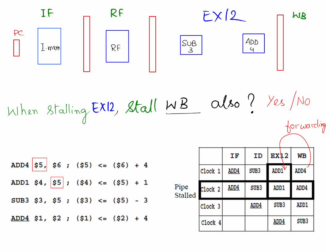
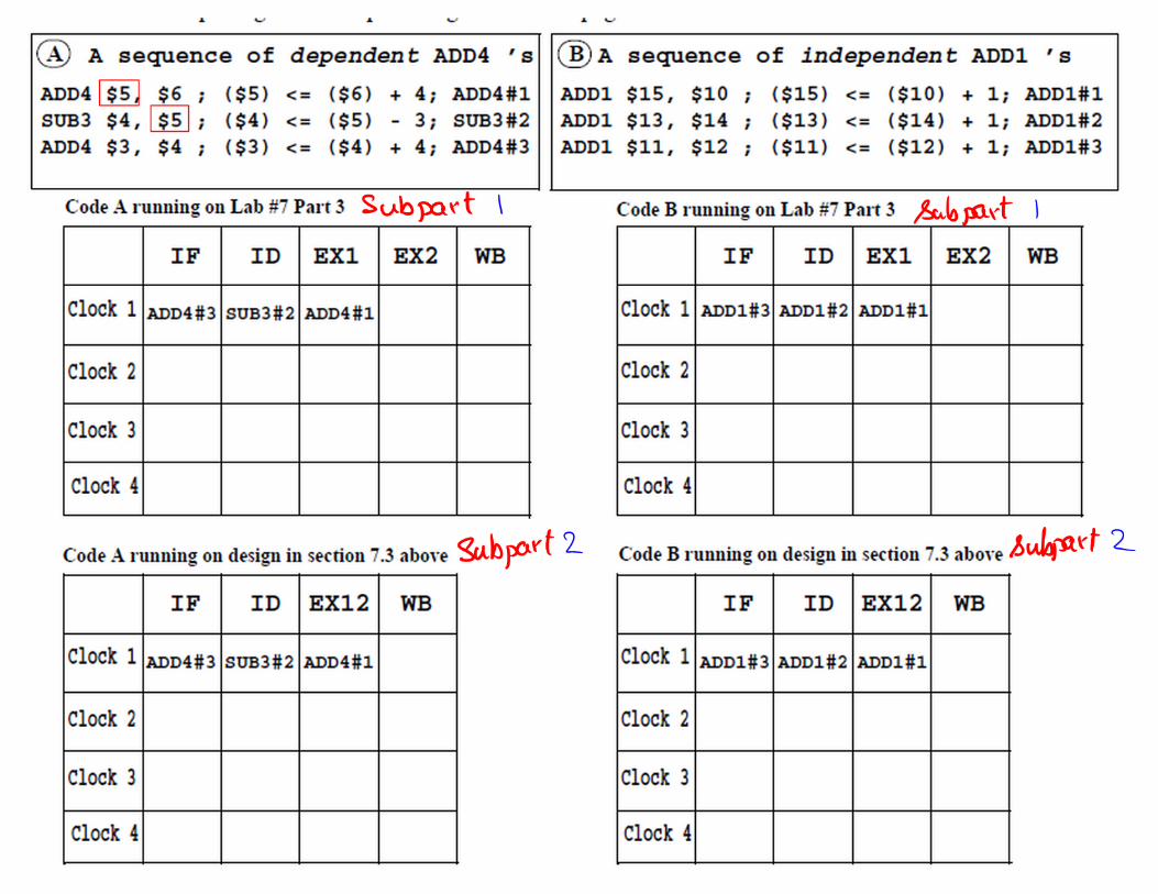
IF ID EX1 EX2 WBComp Station in ID Stage
Q
ID_XA EX1_RA ID_XA EX2_RA
P=Q P=Q
ID_XMEX1= ID_XA Matched with EX1_RA
XD
HDU
EN
XM
EX1
XM
EX2
A-3 A+4
EN
XM
EX1
FU1
EN
RD
Writ
e
RA
FU2
XD
XD
EX1_ADD4
EX1_SUB3
EX1_ADD1
EX1_RA
PRIORITY0 1
RESET_BRESET_B RESET_B RESET_B
1. Complete all missing connections to the Reg. File. Also complete the RA(Result Addreee) connection in ID stage (ID_RA).2. Complete all five enable (EN) controls on the pipeline registers (including PC).
4. Complete the skip controls(SKIP1,SKIP2).5. Draw the logic for the HDU, FU1, and FU2, producing STALL, PRIORITY, FORW1, FORW2.
EX2_ADD4
EX2_SUB3
EX2_ADD1EX2_RA
WB_RA
WB_Write
WB_RDX1_Mux
R1_Mux X2_Mux
R2_Mux
SKIP
1
SKIP
2
Qualifying signals
Qualifyingsignals
QualifyingSignals
LAB 7 Part 3 Block Diagram
I-MEMEN
RESET_B
PRIORITYEX2_XMEX1
ADD4SUB3STALL
EN
FOR
W1 FO
RW
2
Fig. 1
ADD4
SUB3
AD
D1
RAM
OV
ADD4
SUB3
AD
D1
RA
MO
V
ADD4
SUB3
AD
D1
RA
MO
V
EX1_MOVEX2_MOV
revised 7/18/2010
3. Complete the forwarding path from EX2 to EX1. Should it start from upstream or downstream of the X2_mux?

PC
XA
Reg. File
XA
RA
RDR-Write
0
1
0
10
1
A
Cout
A
Cout
Comp Station in ID Stage
ID_XMEX12
P
IF ID EX12 WBComp Station in ID Stage
Q
ID_XA EX12_RA
P=Q
ID_XMEX12 = ID_XA Matched with EX12_RA
XD
EN
XMEX
12
A-3 A+4
FU
EN
RD
Writ
e
RA
XD
EX12_RA
EX12_ADD4
EX12_SUB3
EX12_ADD1 WB_RA
WB_Write
WB_RDX_Mux
R1_MuxR2_Mux
SKIP
1
SKIP
2
Qualifying signals
LAB 7 Part 3 with EX1 and EX2 merged Block Diagram
I-MEMEN
ADD4SUB3
EN
FORW
D QCLKCLRCLK
1. Complete the missing connections to the register file.2. Design the forwarding unit. Generate SKIP1 and SKIP2 signals.3. Use the flip-flop in EX12 stage to get one extra clock for ADD1 instruction.4. Control the EN (ENABLE) control signal on PC and the three stage registers IF/ID, ID/EX12, and EX12/WB.
ADD4
SUB3
AD
D1
RA
MO
V
ADD4
SUB3
AD
D1
RA
MO
V
EX12_MOV
RESET_B
RESET_BRESET_B
RESET_B
RESET_B


