use of electromagnetic clutch water pumps in vehicle engine cooling systems to reduce fuel...
TRANSCRIPT

at SciVerse ScienceDirect
Energy 57 (2013) 624e631
Contents lists available
Energy
journal homepage: www.elsevier .com/locate/energy
Use of electromagnetic clutch water pumps in vehicle engine coolingsystems to reduce fuel consumption
Yoon Hyuk Shin a, Sung Chul Kim a,*, Min Soo Kimb
aGreen Car Powertrain R&D Division, Korea Automotive Technology Institute, Chungnam 330-912, Republic of Koreab School of Mechanical and Aerospace Engineering, Seoul National University, Seoul 151-744, Republic of Korea
a r t i c l e i n f o
Article history:Received 28 November 2012Received in revised form29 April 2013Accepted 30 April 2013Available online 21 June 2013
Keywords:Electromagnetic clutch water pumpPlanetary gearFuel consumptionWarm-upNEDC (New European Driving Cycle)
* Corresponding author. Tel.: þ82 41 559 3093; faxE-mail address: [email protected] (S.C. Kim).
0360-5442/$ e see front matter � 2013 Elsevier Ltd.http://dx.doi.org/10.1016/j.energy.2013.04.073
a b s t r a c t
In general, when the internal combustion engine of a vehicle is started, its operationally connectedcooling system provides excessive cooling, resulting in unnecessary energy consumption and excessiveemission of exhaust gas. If the rotational speed of the engine is high, the excessive cooling causes thecombustion efficiency to decrease. Therefore, better control of the operating temperature range of theengine through use of an active cooling system can achieve better fuel economy and reduction of exhaustgas emission. Effective control of the cooling system in accordance with the operating conditions of theengine can be realized by changing the mass flow rate of the coolant. In this study, we designed elec-tromagnetic clutch water pumps that can control the coolant flow. We made two types of water pump:(1) a planetary gear (PG)-type water pump which can reduce the rotation speed of the water pump by65%, compared with a pulley; and (2) an on/off-type water pump which can completely stop the rotationof the impeller. The performance evaluation of these pumps consisted of a warm-up test and the NewEuropean Driving Cycle (NEDC). Warm-up test results showed that the time required to achieve atemperature of approximately 80 �C with the PG water pump and the on/off water pump was improvedby 7.3% and 24.7% respectively, compared with that of a conventional water pump. Based on the NEDCresults, we determined that the fuel economy of the engine using the PG water pump and the on/offwater pump was improved by 1.7% and 4.0% compared with the fuel economy when using the con-ventional water pump. The application of clutch water pumps is expected to contribute to theimprovement of engine cooling system performance, because their effect in reducing the fuel con-sumption rate is similar to that of an electric water pump.
� 2013 Elsevier Ltd. All rights reserved.
1. Introduction
As fossil fuel problems and environmental issues have becomeincreasingly critical, the development of ecotechnologies toimprove the energy efficiency of vehicles is increasingly important.Furthermore, regulations for automobile fuel consumption andemission control have been become stringent internationally. InEurope, Euro 6 will take effect, and in the USA, the issue of CO2
emission control is an important consideration in enactment ofnew statutes.
Recently, hybrid electric vehicles have been actively studied as agood means of reducing energy usage and harmful emissions [1,2].However, aside from studies on improving the energy efficiency ofelectric and hybrid electric vehicles, there is renewed interest inefficiency enhancement technologies for the traditional internal
: þ82 41 559 3070.
All rights reserved.
combustion engine. These technologies have been regarded asvaluable again in recent years, because advanced technologies havebeen developed that can be applied to traditional vehicles at lowcost and with comparative ease. Other studies are needed toimprove the efficiency of the heavy-duty diesel engine.
High-efficiency technology to save fuel in conventional vehicleshas been suggested for various parts of the vehicle system. Repre-sentative methods of vehicle improvement include reductions inweight and air resistance, and improvements in thermal efficiency.In particular, optimization of the typical cooling system for internalcombustion engines is a field of interest for developing high energyefficiency in vehicles [3e5]. Because vehicle safety is more impor-tant than energy efficiency, the enhanced management of enginethermal characteristics has resulted in realizing advanced functionsin vehicles such as compact front-end module and active thermalmanagement system [6,7].
The typical engine cooling system consists of a water pump,thermostat, radiator, and engine block water jacket. Conventional

Fig. 1. Design and photo of the electromagnetic clutch.Fig. 2. Design of the PG water pump to be two-speed gear.
Fig. 3. Cross-section of the PG water pump design.
Y.H. Shin et al. / Energy 57 (2013) 624e631 625
mechanical water pumps are operated in proportion to the enginespeed to circulate the coolant in the cooling system. In this config-uration, the direct connection between the engine crank shaft andthe water pump results in an excessive mass flow rate of coolants atengine cold start and under partial load conditions. To avoid theexcessive cooling effect and meet the need for high efficiency in thecooling system, electrification of the cooling components has beenproposed as a good alternative. As a result, the electric water pumpsand intelligent thermostat valves have been used in vehicle coolingsystems [8e10]. The electric components can provide efficientcooling on demand under all operating conditions by changing thecoolant mass flow rate. The electric water pump’s efficiency ishigher than that of the conventional mechanical water pump.However, the electrical energy for and electric pump (and otherelectric features of the vehicle) comes from the transformation ofmechanical to electrical energy by the alternator, which occurs withan energy efficiency of less than 60% [11]. In addition, electric pumpsare not regarded as being fail-safe, as opposed to a mechanicalpump, which is belt-driven. Considering these weaknesses of elec-tric water pumps, it is important to modify and improve the me-chanical water pump in conventional vehicles [12].
Furthermore, improving the engine cooling system for heavy-duty vehicles is very important [13]. Given their high rate of fuelconsumption, the effect of fuel savings is significantly greater.
Generally, for heavy-duty diesel engines, the mass flow rate of thecoolant is relatively high at low engine speeds. Therefore, a waterpump is needed that will properly change the impeller speed inaccordance with the thermal load.

Table 1Material properties used in the FEM analysis.
Material properties Structural steel(clutch)
Aluminumalloy (pulley)
Young’s modulus (GPa) 200 71Density (kg/m3) 7800 2770Poisson’s ratio 0.29 0.33Tensile yield strength (MPa) 373 280
Table 2Boundary conditions of structural analysis.
Boundary conditions
Pump speed (rpm) 4200Belt tension (N) 600Torque (N m) 2.4
Fig. 4. Von Mises stress and deformation distributions of the PG water pump.
Y.H. Shin et al. / Energy 57 (2013) 624e631626
In the current study, we suggest a method to improve the fuelefficiency of the internal combustion engine by using an electro-magnetic clutch water pump that can control the engine coolingsystem at both low and high coolant mass flow rates. We made twokinds of electromagnetic clutch water pumps for supply coolants tothe engine cooling system by the operation of an electromagneticclutch equipped in a pulley. The first type is the planetary gear (PG)water pump, and the second is the on/off-type water pump. Theperformance of the pumps in reducing fuel consumption and CO2
emission was demonstrated by experimental means.The analysis of the design for and performance of the clutch
water pumps will form the basis of improvements to the efficiencyof the internal combustion engine cooling system. In addition, useof an electromagnetic clutch water pump will be a reasonablemethod to improve fuel consumption of a heavy-duty engine.
2. Design and development of clutch water pump
In a conventional mechanical water pump, the impeller isoperated by a pulley and belt connected to the engine crankshaft.However, with an electromagnetic clutch water pump, the rotationspeed is controlled by the transfer of the engine speed from thepulley to the water pump’s impeller, which makes the coolingsystem function effectively.
To better control the mass flow rate of coolant in an internalcombustion engine, we designed and manufactured two kinds ofelectromagnetic clutch water pumps: the PG water pump and theon/off water pump. Both pumps have a pump part that is already inexistence, as well as a pulley part that includes the newly designedelectromagnetic clutch. For the PG water pump, the planetary gearis added in the pulley part to change the speed of the impeller.
2.1. Design of clutch water pump
We designed the electromagnetic clutch part to consist of a coil,coil housing and back plate, and other parts.We designed the coil to
Table 3Results of structural analysis.
Part of the water pump Max. VonMises stress (MPa)
Max. deformation(mm)
Pulley 72.5 0.105Planetary gear 102.4 0.088Gear pin 106.5 0.064Disc, shaft & hub 130.1 0.07
have the proper resistance value to minimize power consumption.In addition, we adjusted the coil diameter and number of turns toattain the minimum heating value. As shown in Fig. 1, we alsodesigned the electromagnetic clutch to be a single item; this wasdone by designing the coil housing and back plate for easy assemblyof the parts and attainment of sufficient clamping force.
As shown in Fig. 2, we designed the PG water pump to be a two-speed gear. Fig. 3 shows a cross-sectional diagram of the PG waterpump including the electromagnetic clutch. In addition to the PGpump, we designed an on/off water pump that transfers rotation of
Fig. 5. Schematic diagram of an engine cooling system.
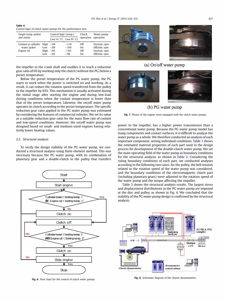
Table 4Control logic of clutch water pumps for the performance test.
Target temp. pointsand status
Control logic (temp.) Clutchoperation
Water pumpoperation
Case A (�C) Case B (�C)
Coolant at cylinderwater jacket
High >94 >110 Off On/max. rpmLow <89 <105 On Off/min. rpm
Engine oil High >85 >101 Off On/max. rpmLow <82 <98 On Off/min. rpm
Fig. 7. Photos of the engine room equipped with the clutch water pumps.
Y.H. Shin et al. / Energy 57 (2013) 624e631 627
the impeller to the crank shaft and enables it to reach a reductiongear ratio of 0% byworking only the clutch (without the PG) belowapreset temperature.
Below the preset temperature of the PG water pump, the PGstarts to work when the power is switched on and working. As aresult, it can reduce the rotation speed transferred from the pulleyto the impeller by 65%. This mechanism is usually activated duringthe initial stage after starting the engine and during low-loaddriving conditions when the coolant temperature is lower thanthat of the preset temperature. Likewise, the on/off water pumpoperates its clutch according to the preset temperature. The specificreduction gear ratio applied to the PG water pump was estimatedby considering the features of commercial vehicles. We set its valueas a suitable reduction gear ratio for the mass flow rate of coolantand low-speed conditions. However, the on/off water pump wasdesigned based on small- and medium-sized engines having rela-tively lower heating values.
2.2. Structural analysis
To verify the design stability of the PG water pump, we con-ducted a structural analysis using finite element method. This wasnecessary because the PG water pump, with its combination ofplanetary gear and a double-clutch in the pulley that transfers
Fig. 6. Flow chart for the control of clutch water pumps.
power to the impeller, has a higher power transmission than aconventional water pump. Because the PG water pump model hasmany components and contact surfaces, it is difficult to analyze thewater pump as awhole.We therefore conducted an analysis of eachimportant component, setting individual conditions. Table 1 showsthe estimated material properties of each part used in the designprocess for development of the double-clutch water pump. We setthe main operating field of the water pump as boundary conditionsfor the structural analysis, as shown in Table 2. Considering theruling boundary conditions of each part, we conducted analysesaccording to the following two cases: for the pulley, the belt tensionrelated to the rotation speed of the water pump was considered,and the boundary conditions of the electromagnetic clutch part(including planetary gears) were adjusted to the rotation speed ofthe water pump and the torque affecting the impeller.
Table 3 shows the structural analysis results. The largest stressand displacement distributions in the PG water pump are imposedat the disc and pulley, as shown in Fig. 4. We concluded that thestability of the PGwater pump design is confirmed by the structuralanalysis.
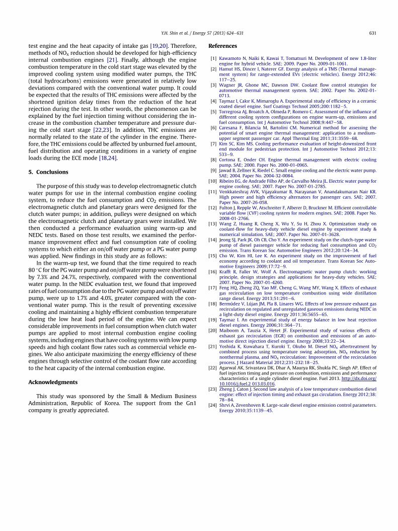
Fig. 8. Schematic diagram of the chassis dynamometer.

Table 5Specifications of the vehicle and the chassis dynamometer.
Item Value
Vehicle Displacement 2900 ccTurbocharger VGTIdle condition 800 rpm
Chassisdynamometer
Vehicle mass simulation 453e5443 kgMax speed 200 km/hRoll diameter Single roll 48 inch (1220 mm)
Y.H. Shin et al. / Energy 57 (2013) 624e631628
3. Control algorithm and experimental equipment
To evaluate the performance of the clutch water pumps, wedeveloped a control method for the water pumps and prepared apractical application of the water pump, as well as experimentalequipment including a chassis dynamometer. Various vehicles thatare suitable for the experimental environment and comparativeevaluation, and that can also show maximum performance, varyaccording to the features of their types. For this study, we chose tomake clutch water pumps using a medium-size 2.9 L engine from ageneral diesel vehicle.
3.1. Water pump control method
To control the clutch water pump, it is necessary to set a stan-dard temperature for operating the clutch and also to install tem-perature sensors. As shown in Fig. 5, we installed temperaturesensors at two points: near the cylinder water jacket that wouldhave the highest temperature along the coolant’s path through theengine cooling system, and near the bottom of the engine oil pan.
The control conditions were set as shown in Table 4, and dividedinto Cases A and B. We used the coolant temperature near thecylinder water jacket and the engine oil temperature near the oilpan as control variables [14]. Because it is known that the engineshows a good performance at about 105e110 �C, and the engine
Fig. 9. The Engine rpm and speed pr
does not perform well above this temperature range due to over-heating, we set this temperature as the maximum temperature inCase B [15]. When the controlled temperature reaches the low-temperature condition and is activated by the 12 V power trans-fer, the rotation speed of the impeller goes down to its minimumvalue, which is adjusted to the features of the newly developedwater pump. On the other hand, when the controlled temperaturereaches the high-temperature condition, the clutch does not workand the water pump operates in the same way as a conventionalwater pump. This means that the stability of the engine coolingsystem is secured because the water pump is always operating,evenwhen power is not transferred or the clutch is malfunctioning.While the control logic is set as Case A and B for the on/off waterpump, in the case of the PG water pump, we controlled only Case Abecause its maximum control temperature was relatively low. Thereason is that the increase in coolant temperature is limited in theperformance test because the PG water pump, unlike the on/offwater pump, keeps the coolant flowing. Fig. 6 has a flow chart thatshows the control process based on the temperatures of the coolantand engine oil.
3.2. Test methods and equipment
To use control logic and a controller developed for performanceevaluation of clutch water pumps, we installed temperature sen-sors at sensing points for the coolant temperature near the cylinderwater jacket and the engine oil temperature near the oil pan. Wealso installed another temperature sensor at the radiator inlet.These temperature sensors, K-type thermocouples, have a mea-surement range of 0e800 �C and a margin of error of �0.2 �C. Dataacquisition equipment, which can identify variable flow rates andsave temperature values at each point, was connected to thevehicle. As shown in Fig. 7, we installed clutch water pumpsdeveloped for performance evaluation in the test vehicle (variablegeometry turbocharger engine of 2900 cc). The performance
ofile of the test vehicle in NEDC.

Table 6Power consumption of the electromagnetic clutch.
Sample 1 Sample 2
1 2 3 4 1 2 3 4
Input voltage (V) 12 12Current consumption (A) 1.660 1.679 1.671 1.670 1.676 1.658 1.679 1.687Power consumption (W) 19.92 20.15 20.05 20.04 20.11 19.90 20.15 20.24Average of power consumption (W) 20.04 20.1
Y.H. Shin et al. / Energy 57 (2013) 624e631 629
evaluation consisted of a warm-up test and the NEDC (New Euro-pean Driving Cycle) using a chassis dynamometer, as shown inFig. 8. Fig. 8 is a schematic diagram of the system equipment,consisting of a chassis dynamometer (AVL, RPL1220) and a gasanalyzer (PIERBURG, AMA2000C) to evaluate NEDC performance;Table 5 lists the specifications of the vehicle and the chassisdynamometer.
For the performance evaluation, we equilibrated the test vehiclein a chamber of ordinary temperature (25 �C) for more than 6 h. The
Fig. 10. Temperature change in Warm-up test (Case A).
warm-up test was conducted by measuring the time it took for thecoolant temperature to reach 80 �C after the engine started. Asshown in Fig. 9, the NEDC test consists of ECE15(Part 1) andEUDC(Part 2) driving cycles, which are used in Korea to test the fuelefficiency and exhaust emissions of diesel vehicles. The totalmileage of the driving cycle was 11.01 km and the time to completethis distance was 1180 s. The NEDC test was repeated three timeseach for the conventional and two electromagnetic water pumps tofind the reliability of the test vehicle fuel economy and CO2emissions.
4. Test results and discussion
4.1. Electromagnetic clutch test
The power consumption of the electromagnetic clutch in thedeveloped water pump was tested on two samples; tests wererepeated four times per sample. The results showed that the powerconsumption was approximately 20 W under almost all operatingconditions, as shown in Table 6. The additional power wasconsumed in the solenoid actuator of the electromagnetic clutch.Considering the total power of a combustion engine, the additionalpower consumption in the electromagnetic clutch water pump is areasonable method for enhancing the engine efficiency [16].
4.2. Warm-up test
Fig. 10(a) shows a comparison of the coolant temperaturechanges that occurred in the cylinder water jacket of the PG waterpump with variable-volume flow rate and the on/off water pumpwith electromagnetic clutch. These two pumpswere also comparedwith a conventional-type pump. The coolant temperature changeswere figured out through the warm-up tests for the two clutch-type pumps. Fig. 10(b) shows the coolant temperature changes inthe radiator inlet for the same conditions asmentioned above.Withthese results, we can get a more accurate comparison of the ther-mostat’s opening time for each water pump and certainly confirmthe shortening of the warm-up time.
The warm-up test results in Table 7 show that the times for thePG and on/off water pumps to reach 80 �C were shortened by 153 sand 516 s, respectively, compared with the base water pump. Thismeans that the warm-up times of the PG and on/off water pumpswere shorter by 7.3% and 24.7%. The time required for the engine towarm up to 80 �C was proportionately shortened due to thedecreased rotation speed of the impeller, according to its controlcondition during warm-up. By using clutch water pumps, the initial
Table 7Results of the warm-up test.
Type of water pump Control logic Warm-up time (s)
Base e 2082PG Case A 1929On/off Case A 1566

Table 8Results of the NEDC test.
Type of waterpump
Control logic Fuel consumption(km/L)
CO2 emission(g/km)
Base W/P e 10.039 265.17PG W/P Case A 10.215 260.61On/off W/P Case A 10.353 257.14
Case B 10.450 254.73
Y.H. Shin et al. / Energy 57 (2013) 624e631630
coolant workload can be reduced when the vehicle engine is star-ted, resulting in a reduction in fuel consumption. We can thencompare the features of the clutch water pumps to each other, aswell as the characteristics of their coolant temperature changes.The on/off water pump is a cooling systemwith a high pump speedand low coolant flow rate, and is therefore suitable for relativelysmall- and medium-sized engines that can rapidly change theirtemperature rapidly because of low heat capacity. On the otherhand, the PG water pump is suitable for heavy-duty engines withhigh heat capacity because of its cooling system with a low pumpspeed and high flow rate of coolant.
4.3. The New European Driving Cycle test
Fig. 11(a) shows the coolant temperature change in the cylinderwater jacket during the NEDC test. The on/off water pump shows amuch higher temperature range than the base water pump, due tothe warm-up effect in the early stage of the test. Fig. 10(b) alsoshows the coolant temperature change at the radiator inlet. Fromthe NEDC evaluation test for the clutch water pumps, we can getthe results for fuel consumption and CO2 emissions, as shown in
Fig. 11. Temperature change in NEDC test.
Table 8. When compared with the conventional water pump, theclutch water pumps generally showed improved fuel consumptionand CO2 emissions; the improvements in PGwater pump and on/offwater pump were up to 1.7%e1.8% and 4.0%e4.1%, respectively. Weconducted experiments on medium-sized diesel engine vehicles tocompare the performance of the PG water pump, which has suit-able properties for application to commercial vehicles, to that of theon/off water pump. The result shows a slight decrease in theimprovement in fuel consumption, compared with that of the on/off water pumps. The reason for the difference is believed to be dueto the fact that rapid control of the coolant in an on/off water pumpis more suitable when the heat capacity of the test vehicle’s engineis considered.
Generally, emissions in the cold start stage are important forevaluating the effects of improvements on an internal combustionengine. Fig. 12 shows the emissions, CO2, and fuel economy of theECE (Part 1) mode at the cold start stage. The CO (carbonmonoxide)emissions in ECE modewere reduced by approximately 6.4%e21.6%as a result of the high combustion temperature, when using elec-tromagnetic clutch water pumps instead of a conventional waterpump for the engine cooling system. The cylinder wall temperaturewas increased as the heat rejection of the test engine in cold startstage was decreased by controlling the engine coolant flow rate.The higher cylinder temperature in the diesel engine can reduce theignition delay period during the ECE mode. In other words, thatmeans the oxidation of CO to CO2 can be enhanced. The combustioncondition for a general diesel engine is commonly lean. Therefore,the higher combustion temperature could affect strongly thereduction of CO emissions [17]. The CO2 emissions in the ECE modewere reduced by approximately 2.4%e6.8%. In addition, the fueleconomy during the ECE mode was enhanced by 2.3%e7.0%. Theimprovement effect in ECE mode was greater than in EUDC (Part 2)mode. The reason for the reduction in fuel consumption is that asthe cycle evolves, the engine warms up and engine losses decreasedue to lower friction losses and temperature gradients [18]. On theother hand, the NOx (nitrogen oxides) emissions were slightlyhigher because the higher temperature in the combustion cylinderhad been occurred by the decrease of both the heat rejection of the
Fig. 12. Emissions, CO2 and fuel economy in the ECE (Part 1) mode.
Y.H. Shin et al. / Energy 57 (2013) 624e631 631
test engine and the heat capacity of intake gas [19,20]. Therefore,methods of NOx reduction should be developed for high-efficiencyinternal combustion engines [21]. Finally, although the enginecombustion temperature in the cold start stage was elevated by theimproved cooling system using modified water pumps, the THC(total hydrocarbons) emissions were generated in relatively lowdeviations compared with the conventional water pump. It couldbe expected that the results of THC emissions were affected by theshortened ignition delay times from the reduction of the heatrejection during the test. In other words, the phenomenon can beexplained by the fuel injection timing without considering the in-crease in the combustion chamber temperature and pressure dur-ing the cold start stage [22,23]. In addition, THC emissions arenormally related to the state of the cylinder in the engine. There-fore, the THC emissions could be affected by unburned fuel amount,fuel distribution and operating conditions in a variety of engineloads during the ECE mode [18,24].
5. Conclusions
The purpose of this study was to develop electromagnetic clutchwater pumps for use in the internal combustion engine coolingsystem, to reduce the fuel consumption and CO2 emissions. Theelectromagnetic clutch and planetary gears were designed for theclutch water pumps; in addition, pulleys were designed on whichthe electromagnetic clutch and planetary gears were installed. Wethen conducted a performance evaluation using warm-up andNEDC tests. Based on those test results, we examined the perfor-mance improvement effect and fuel consumption rate of coolingsystems to which either an on/off water pump or a PG water pumpwas applied. New findings in this study are as follows:
In the warm-up test, we found that the time required to reach80 �C for the PGwater pump and on/off water pumpwere shortenedby 7.3% and 24.7%, respectively, compared with the conventionalwater pump. In the NEDC evaluation test, we found that improvedrates of fuel consumptiondue to thePGwater pumpandon/offwaterpump, were up to 1.7% and 4.0%, greater compared with the con-ventional water pump. This is the result of preventing excessivecooling and maintaining a highly efficient combustion temperatureduring the low heat load period of the engine. We can expectconsiderable improvements in fuel consumptionwhen clutch waterpumps are applied to most internal combustion engine coolingsystems, includingengines that have cooling systemswith lowpumpspeeds and high coolant flow rates such as commercial vehicle en-gines. We also anticipate maximizing the energy efficiency of theseengines through selective control of the coolant flow rate accordingto the heat capacity of the internal combustion engine.
Acknowledgments
This study was sponsored by the Small & Medium BusinessAdministration, Republic of Korea. The support from the Gn1company is greatly appreciated.
References
[1] Kawamoto N, Naiki K, Kawai T, Tomatsuri M. Development of new 1.8-literengine for hybrid vehicle. SAE; 2009. Paper No. 2009-01-1061.
[2] Hamut HS, Dincer I, Naterer GF. Exergy analysis of a TMS (Thermal manage-ment system) for range-extended EVs (electric vehicles). Energy 2012;46:117e25.
[3] Wagner JR, Ghone MC, Dawson DW. Coolant flow control strategies forautomotive thermal management system. SAE; 2002. Paper No. 2002-01-0713.
[4] Taymaz I, Cakır K, Mimaroglu A. Experimental study of efficiency in a ceramiccoated diesel engine. Surf Coatings Technol 2005;200:1182e5.
[5] Torregrosa AJ, Broatch A, Olmeda P, Romero C. Assessment of the influence ofdifferent cooling system configurations on engine warm-up, emissions andfuel consumption. Int J Automotive Technol 2008;9:447e58.
[6] Caresana F, Bilancia M, Bartolini CM. Numerical method for assessing thepotential of smart engine thermal management: application to a medium-upper segment passenger car. Appl Thermal Eng 2011;31:3559e68.
[7] Kim SC, Kim MS. Cooling performance evaluation of height-downsized frontend module for pedestrian protection. Int J Automotive Technol 2012;13:533e9.
[8] Cortona E, Onder CH. Engine thermal management with electric coolingpump. SAE; 2000. Paper No. 2000-01-0965.
[9] Jawad B, Zellner K, Riedel C. Small engine cooling and the electric water pump.SAE; 2004. Paper No. 2004-32-0084.
[10] Ribeiro EG, de Andrade Filho AP, de Carvalho Meira JL. Electric water pump forengine cooling. SAE; 2007. Paper No. 2007-01-2785.
[11] Venkkateshraj AVK, Vijayakumar B, Narayanan V, Anandakumaran Nair KR.High power and high efficiency alternators for passenger cars. SAE; 2007.Paper No. 2007-26-058.
[12] Fulton J, Repple W, Atschreiter F, Alberer D, Bruckner M. Efficient controllablevariable flow (CVF) cooling system for modern engines. SAE; 2008. Paper No.2008-01-2766.
[13] Wang Z, Huang R, Cheng X, Wu Y, Su H, Zhou X. Optimization study oncoolant-flow for heavy-duty vehicle diesel engine by experiment study &numerical simulation. SAE; 2007. Paper No. 2007-01-3628.
[14] Jeong SJ, Park JK, Oh CB, Cho Y. An experiment study on the clutch-type waterpump of diesel passenger vehicle for reducing fuel consumption and CO2emission. Trans Korean Soc Automotive Engineers 2012;20:124e34.
[15] Cho W, Kim HI, Lee K. An experiment study on the improvement of fueleconomy according to coolant and oil temperature. Trans Korean Soc Auto-motive Engineers 2009;17:72e9.
[16] Krafft R, Faller W, Wolf A. Electromagnetic water pump clutch: workingprinciple, design strategies and applications for heavy-duty vehicles. SAE;2007. Paper No. 2007-01-4260.
[17] Feng HQ, Zheng ZQ, Yao MF, Cheng G, Wang MY, Wang X. Effects of exhaustgas recirculation on low temperature combustion using wide distillationrange diesel. Energy 2013;51:291e6.
[18] Bermúdez V, Lújan JM, Pla B, Linares WG. Effects of low pressure exhaust gasrecirculation on regulated and unregulated gaseous emissions during NEDC ina light-duty diesel engine. Energy 2011;36:5655e65.
[19] Taymaz I. An experimental study of energy balance in low heat rejectiondiesel engines. Energy 2006;31:364e71.
[20] Maiboom A, Tauzia X, Hetet JF. Experimental study of various effects ofexhaust gas recirculation (EGR) on combustion and emissions of an auto-motive direct injection diesel engine. Energy 2008;33:22e34.
[21] Yoshida K, Kuwahara T, Kuroki T, Okubo M. Diesel NOx aftertreatment bycombined process using temperature swing adsorption, NOx reduction bynonthermal plasma, and NOx recirculation: Improvement of the recirculationprocess. J Hazard Material 2012;231-232:18e25.
[22] Agarwal AK, Srivastava DK, Dhar A, Maurya RK, Shukla PC, Singh AP. Effect offuel injection timing and pressure on combustion, emissions and performancecharacteristics of a single cylinder diesel engine. Fuel 2013. http://dx.doi.org/10.1016/j.fuel.2 013.03.016.
[23] Zheng J, Caton J. Second law analysis of a low temperature combustion dieselengine: effect of injection timing and exhaust gas circulation. Energy 2012;38:78e84.
[24] Shrvi A, Zevenhoven R. Large-scale diesel engine emission control parameters.Energy 2010;35:1139e45.