use of geothermal energy in dairy processing
TRANSCRIPT

6 GHC BULLETIN, NOVEMBER 2012
USe of GeoThermal enerGy in dairy ProceSSinGJack Kiruja, Geothermal Development Company, Nairobi, Kenya
abstractThe growth of industries is dependent on the availability and
affordability of energy. However, conventional energy sources such as fossil fuels are getting depleted and their price is increasing rapidly due to market forces and world politics. It is therefore necessary to consider alternative sources of energy and geothermal energy is a potential option. Geothermal energy can be utilized for both electricity generation and direct uses such as heating and cooling. The dairy industry in Kenya can benefit immensely from the vast geothermal energy in the country since both dairy farming and the geothermal resources are located in the same region i.e. the Rift Valley region. Furthermore, dairy processing involves both heating and cooling operations, whose energy requirements are within a range for the geothermal resource in Kenya to cater. This paper discusses some of the dairy processing operations which can utilize geothermal energy and the appropriate technology which can be applied for each operation. The energy demand and the cost of each operation are also discussed.
introductionKenya is largely an agricultural country in which crop
cultivation, livestock keeping, fisheries and beekeeping are the main activities especially in the rural areas where most of the population live. These activities are practiced in different parts of the country depending on the prevailing climatic conditions of the region and the customs of the people living in that region.
Livestock keeping has been practiced for centuries in Kenya, mainly in the semiarid North and North-eastern parts of the country where the drought resistant Zebu cattle are the main breed. Traditionally the cattle were kept to provide milk and blood which were the main diet at the time and as a measure of wealth. However, with the coming of the European settlers, new breeds of cattle were introduced into the country mainly for milk production. These included Friesian, Ayrshire and Guernsey among others (EPZA, 2005).
Dairy farming is practiced extensively in the Central highlands and in the Rift Valley region of Kenya. The output from these regions account for about 80% of the milk produced in the country (KDB, 2010). Table 1 below shows the areas of the country in which dairy farming is most active. It is important to note that Nakuru and Naivasha are in the Rift Valley while Nairobi gets most of the milk from Kiambu which is in the Central region.
Since the liberalization of the dairy industry in 1992, there has been an increased entry of milk processors in the market. Among the products they process are liquid pasteurized milk, yoghurt, cheese, ice cream and ghee (EPZA, 2005). Liquid pasteurized milk is by far the largest output due to its huge demand in the country especially in the urban centres. There are wide discrepancies in milk consumption in rural and urban populations and across income groups. However, consumption
at household level is higher in urban than in the rural regions. Statistics for 1999 indicate that the annual per capita consumption of milk in rural areas was 45 litres for milk-producing households and 19 litres for milk-purchasing households, while the urban per capita milk consumption was estimated at 125 litres (KDB, 2009).
table 1. dairies in central kenya and rift valley region (EPZa, 2005).Area Producers Processors Milk Dairies
Nairobi 499 11 6
Mombasa 65 3 -
Nakuru 65 7 2
Naivasha 73 3 2
Initially, large scale dairy farming was the main driver of the dairy industry but at the moment small scale dairy farming accounts for about 70% of the produce (EPZA, 2005). The dairy industry in Kenya has been growing steadily over the years and at the moment; milk production from cows only is about 4 billion litres per year. This is illustrated in Figure 1.
Figure 1. Milk production in Kenya (KDB, 2009).
Energy source for dairy Processing The Kenyan Rift Valley is not only home to dairy farming
but also the largest geothermal resource in Africa. The expansion of geothermal energy production in the country is expected to avail surplus thermal energy. Proper planning for the use of this energy is important prior to reinjecting the water back into the ground.
Kenya’s geothermal resources are high temperature and liquid dominated. This means that large quantities of hot water are produced as by-products of power generation. It is also important to note that some of these geothermal resources are strategically situated in agriculturally rich areas such as Menengai geothermal prospect in Nakuru County. Nakuru town is one of the fastest growing towns in Kenya, where several industries are starting their operations. This provides vast opportunities for utilising the geothermal energy directly.
7GHC BULLETIN, NOVEMBER 2012
The heating and cooling processes of dairy processing can benefit from direct utilisation of the geothermal energy in Menengai. The technology that has been developed to utilise heat to provide cooling is known as absorption refrigeration while pasteurization is the technology for the thermal treatment of milk.
The dairy processing plants in Nakuru are situated close to the geothermal prospect and therefore transporting the geothermal fluid from the source to the target location will be relatively easy. Table 2 shows some of these dairies and their processing capacities. Geothermal wells have already been drilled close to some of these locations, and the use of geothermal fluid in the dairy industry can be considered as a by-product while electricity production is the primary product.
table 2. dairy Plants close to the Geothermal Prospect of menengai (EPZa, 2005).
Processor LocationInstalled Capacity (Lt/Day)
Actual Capacity (Lt/Day)
Spin Knit Dairy Nakuru/Nairobi 150,000 100,000
Lelkina Dairy Molo/Nakuru 30,000 20,000
Kenya Milk Products Nakuru 15,000 6,000
Ilara Rongai/Nakuru 40,000 5,000
Solai Mawa Factory Solai/Nakuru 3,000 2,000
Supa Duka Nakuru 1,500 1,000
Total 239,500 134,000
dairY ProcEssinGMilk starts to go bad within hours once it is out of the body
of the cow. It is therefore important to begin to process it as soon as possible in order to preserve it for longer. Processed milk can be preserved for days or even months depending on the kind of treatment it has been subjected to. The major methods of treatment are chilling, heat treatment and evaporation (Bylund, 1995). It is clear that these are all thermal processes that entail the removal or addition of heat.
chillingChilling is the initial treatment of milk prior to further
processing. The temperature of milk is reduced to 2-4°C so as to slow down the action of microorganisms and enzymes which are responsible for spoilage. In addition, after processing the milk should be cooled again before packaging to secure a longer shelf life. Ice water is used to provide cooling in storage silos and in the cooling section of the pasteurizer.
thermal treatmentThermal treatment involves heating of every particle of
milk or milk product to a specific temperature for a specific period of time without allowing recontamination of that milk or milk product during the heat treatment process. This thermal treatment of milk is done for two major reasons.
Firstly, it should achieve total destruction of all pathogenic microorganisms which could cause diseases in people. Secondly, a significant reduction in the quantity of spoilage enzymes and microorganisms in the milk should be achieved in order to improve the shelf life of the milk from a day or two up to about two weeks (DST, 1999).
In order to meet its objectives without destroying the natural chemical and physical properties of milk as well as the nutrients, a suitable time-temperature combination for heat treatment should be determined. The combination is determined by the concentration of microorganisms to be destroyed, the acceptable concentration of microorganisms that can remain behind after thermal treatment and the thermal resistance of the target microorganisms. This combination is based on the thermal death time of Coxelliae burnettii, which is the most heat resistant pathogen found in milk (Bylund, 1995).
Some of the most common thermal treatment techniques are shown in Table 3 below together with their required time-temperature combinations. Pasteurization is the most common of these techniques and can either be low temperature long time (LTLT) or high temperature short time (HTST).
table 3. the main categories of heat treatment in dairy Processing (bylund, 1995).
Process Temp. (°C) Time (sec.)
Thermisation 63 – 65 15
LTLT pasteurisation of milk 63 1800
HTST pasteurisation of milk 72 – 75 15 – 20
HTST pasteurisation of cream. >80 1 – 5
Ultra pasteurisation 125 – 138 2 – 4
UHT (flow sterilisation) normally 135 – 140 1-3
Sterilisation in container 115 – 120 1200-1800
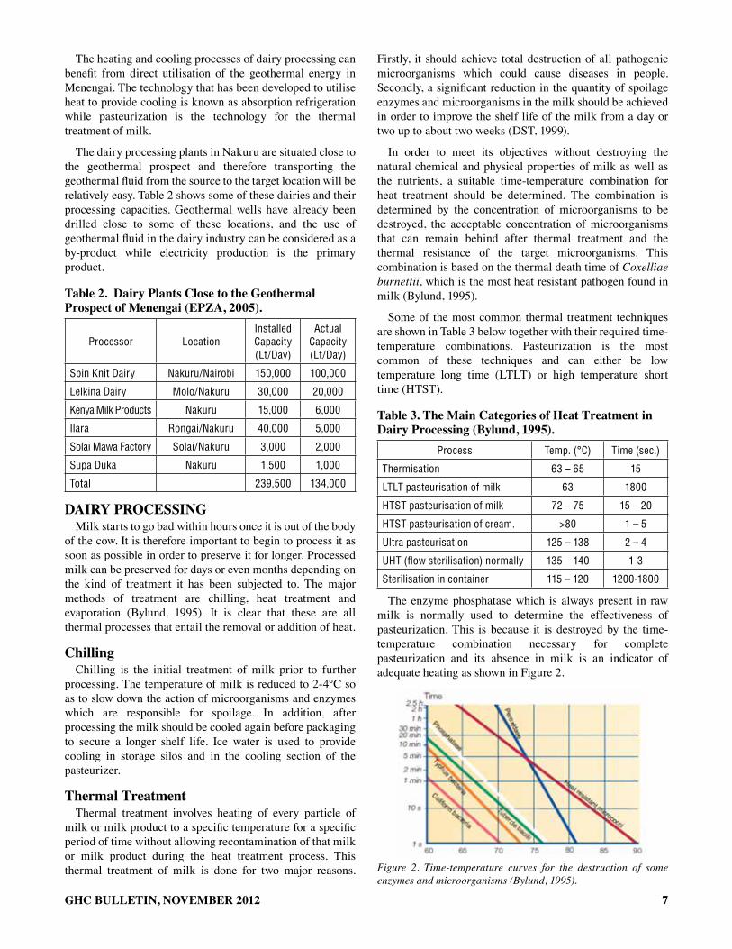
The enzyme phosphatase which is always present in raw milk is normally used to determine the effectiveness of pasteurization. This is because it is destroyed by the time-temperature combination necessary for complete pasteurization and its absence in milk is an indicator of adequate heating as shown in Figure 2.
Figure 2. Time-temperature curves for the destruction of some enzymes and microorganisms (Bylund, 1995).

8 GHC BULLETIN, NOVEMBER 2012
Energy demandsThe growth of industries the world over has relied heavily
on the availability of energy to drive the mechanical, electrical and thermal processes. The energy demand varies from one industry to another with the smelting industries leading with the highest demand.
The energy demand in dairy processing is mainly for heating the water which is used in pasteurization and cleaning of the equipment. Other operations that require energy are running of the machinery, refrigeration of the milk before and after processing to control spoilage and evaporation in order to obtain milk powder. Table 4 below shows the energy consumption in a typical modern dairy.
table 4. data on total consumption of Energy in kWh/litre of Processed milk from some nordic dairies (korsström and lampi, 2002).
Product range* Sweden Denmark Finland Norway
Market milk + cultured products 0.11 – 0.34 0.07 – 0.09 0.16 – 0.28 0.45
Cheese, whey 0.15 – 0.34 0.12 – 0.18 0.27 – 0.82 0.21
Powder, cheese and/or liquid products
0.18 – 0.65 0.30 – 0.71 0.28 – 0.92 0.29 – 0.34
hEat EXchanGErsA heat exchanger is a partition that keeps the hot water, hot
pasteurized milk, unpasteurized milk and cooling water separated during dairy processing. The heat exchangers in dairy processing are made of stainless steel plates which have a good overall heat transfer coefficient and are corrosion resistant. These are the pasteurizer, the regenerator and the cooling section.
Pasteurizer A pasteurizer is the heat exchanger in which the milk
attains the desired temperature from the heating medium. The heating medium could be hot water or low pressure steam but water is preferred. The temperature difference between the milk and the hot water should be maintained at 2-3°C at every point in the pasteurizer to prevent coagulation of the proteins as this will result in fouling (Bylund, 1995). Fouling creates a layer of organic material on the surface of the heat exchanger resulting in a reduction in the heat transfer coefficient of the plates.
regeneratorIn processing, products such as milk are heated and then
cooled. The heat of the pasteurized milk is in most cases used to heat the cold incoming milk. By so doing, the incoming milk is preheated while the outgoing milk is precooled. This saves energy for heating and refrigeration, and it is referred to as heat recovery or regenerative heat exchange. In dairy processing, 90-95% of the energy is recovered through regeneration.
(1)
Where R = regenerative efficiency (%)tr = milk temperature after regeneration (°C)ti = temperature of raw incoming milk (°C)tp = pasteurisation temperature (°C)
cooling sectionAfter pasteurization, a few spoilage microorganisms still
remain in the milk. It is for this reason that milk should be cooled to ≤ 4°C after pasteurization to keep these microorganisms inactive in order to minimise spoilage. Cooling of the milk takes place at the last section of the heat exchanger using ice water at a temperature close to 0°C. In some cases glycol is added to the cooling water to lower its freezing point and attain lower temperatures (Bylund, 1995). Figure 3 below shows the three heat exchangers used in milk pasteurization and cooling in a dairy plant.
Figure 3. Cooling section (1), regenerator (2) and Pasteuriser (3) (Bylund, 1995)
The good overall heat transfer coefficient in the heat exchangers is made possible not only by the thinness and good thermal conductivity of stainless steel plates, but also by the design of the plates. The plates are corrugated to create turbulence in the flow of milk and hot water. Furthermore, the two fluids flow in opposite directions to enhance energy efficiency as shown in Figure 4.
logarithmic mean temperature differenceThe driving force for heat transfer in a heat exchanger is
the temperature difference between the heating medium and the product being heated. The bigger the temperature difference the bigger the quantity of heat transferred. However, the temperature difference when heating milk should be small to avoid fouling in the heat exchanger. Since this temperature difference varies within the heat exchanger, a logarithmic mean value is normally used and it is called Logarithmic mean temperature difference (LMTD).
In order to achieve efficient utilisation of energy during heat transfer, the two fluids should flow in opposite directions i.e. counter current flow, where the cold milk meets the cold heating medium at the inlet, and a progressively warmer medium as it passes through the heat exchanger. During the passage the milk is gradually heated so that the temperature is always only a few degrees below that of the heating medium at the corresponding point as shown in Figure 5.
9GHC BULLETIN, NOVEMBER 2012
Figure 4. Plate heat exchanger (DST, 1999).
Figure 5. Counter current flow of fluids in a heat exchanger (Bylund, 1995).
(2)
The amount of energy transferred across a heat exchanger depends to a large extent on the area of the exchange surface. Area of the heat exchanger is determined as follows:
Q = UAΔTm (3)
Where
A = Required heat transfer area [m2]∆Tm = logarithmic mean temperature difference [°C]U = overall heat transfer coefficient [W/m2K]Q = Heat transfer rate in the heat exchanger [W]
milk PoWdErThe processing of milk powder entails the reduction of
moisture down to 2.5-5% through evaporation and drying. At this moisture content, bacteria cannot grow and therefore, the milk can be stored for up to six months in the case of whole milk and three years for skimmed milk (Bylund, 1995). Not only does drying increase the shelf life of milk but also reduce its volume and weight, and hence saves on transport and storage cost.
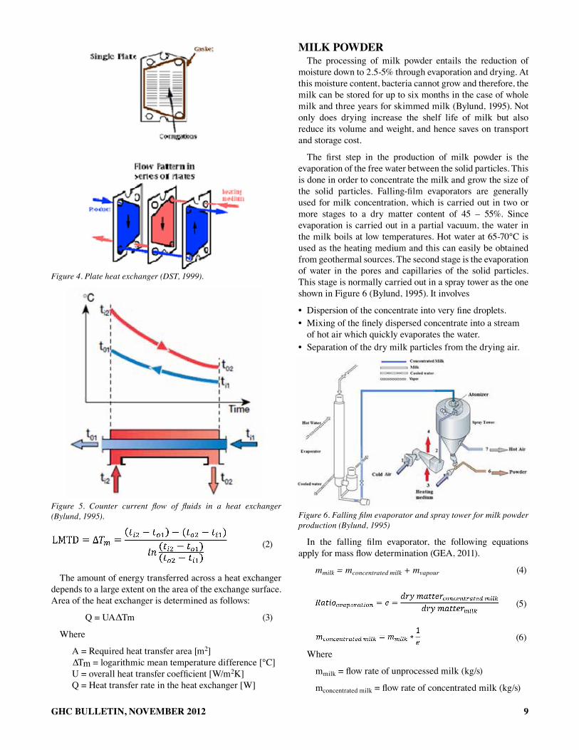
The first step in the production of milk powder is the evaporation of the free water between the solid particles. This is done in order to concentrate the milk and grow the size of the solid particles. Falling-film evaporators are generally used for milk concentration, which is carried out in two or more stages to a dry matter content of 45 – 55%. Since evaporation is carried out in a partial vacuum, the water in the milk boils at low temperatures. Hot water at 65-70°C is used as the heating medium and this can easily be obtained from geothermal sources. The second stage is the evaporation of water in the pores and capillaries of the solid particles. This stage is normally carried out in a spray tower as the one shown in Figure 6 (Bylund, 1995). It involves
• Dispersion of the concentrate into very fine droplets.• Mixing of the finely dispersed concentrate into a stream
of hot air which quickly evaporates the water.• Separation of the dry milk particles from the drying air.
Figure 6. Falling film evaporator and spray tower for milk powder production (Bylund, 1995)
In the falling film evaporator, the following equations apply for mass flow determination (GEA, 2011).
mmilk = mconcentrated milk + mvapour (4)
(5)
(6)
Where
mmilk = flow rate of unprocessed milk (kg/s)
mconcentrated milk = flow rate of concentrated milk (kg/s)
c
___ ~JMI.i"
r::==- \~~ ...... - -
dry matterconcentrated milk Ratioevaporation = e = dry mattermilk
1 mconcentrated nlilk == mmilk * -;

10 GHC BULLETIN, NOVEMBER 2012
mvapor = evaporation rate (kg/s)
dry matterconcentrated milk = dry matter in concentrated milk
dry matter milk = dry matter in unprocessed milk
clEaninGCleaning in dairy processing is very important for hygienic
reasons and for maintaining good energy efficiency in the heat exchangers. This is because during pasteurisation and storage, milk particles stick on the surfaces of the equipment and could harbour bacteria and other harmful microorganisms. These particles usually have insulating properties and reduce the transfer of heat across the surfaces thereby leading to poor energy efficiency.
Cleaning achieves the removal of physical dirt from the surfaces, chemical dirt such as fats and vitamins and finally disinfection. In modern dairies, cleaning in place (CIP) without dismantling the equipment is the common practice and is of two types.
• CIP programs for circuits with pasteurisers and other equipment with heated surfaces.
• CIP programs for circuits with pipe systems, tanks and other process equipment with no heated surfaces.The main difference between the two types is that acid
circulation must always be included in the first type to remove encrusted protein and salts from the surfaces of heat-treatment equipment. A CIP program for a pasteuriser, i.e. hot components, consists of the following stages:
a) Rinsing with warm water for about 10 minutes.b) Circulation of an alkaline detergent solution (0.5 –
1.5%) for about 30 minutes at 75°C.c) Rinsing out alkaline detergent with warm water for
about 5 minutes.d) Circulation of (nitric) acid solution (0.5 – 1.0 %) for
about 20 minutes at 70°C.e) Post-rinsing with cold water.f) Gradual cooling with cold water for about 8
minutes.The pasteuriser is usually disinfected before production
starts. This is typically done by circulating hot water at 90 – 95°C for 10 – 15 minutes.
A CIP program for a circuit with pipes, tanks and other “cold components” can comprise the following stages:
a) Rinsing with warm water for 3 minutes.b) Circulation of a 0.5 – 1.5% alkaline detergent at
75°C for about 10 minutes.c) Rinsing with warm water for about 3 minutes.d) Disinfection with hot water 90 – 95°C for 5
minutes.f) Gradual cooling with cold tap water for about 10
minutes.The Table 5 shows the consumption of water by some
dairies in the Nordic countries.
tablE 5. data on the consumption of Water in litres/litre of Processed milk from some nordic dairies (korsström and lampi, 2002)
Product range Sweden Denmark Finland Norway
Market milk + cultured products
0.96 – 2.8 0.60 – 0.97 1.2 – 2.9 4.1
Cheese, whey 2.0 – 2.5 1.2 – 1.7 2.0– 3.1 2.5 – 3.8
Powder, cheese and/or liquid products
1.7 – 4.0 0.69 – 1.9 1.4 – 4.6 4.6 – 6.3
milk coolinG and cold storaGEMilk has a very short shelf life because it is a medium with
an excellent environment for micro-organisms to thrive. It is therefore important to consume it as soon as possible after production. However, this is not always possible due to the requirement to heat treat it and also because of the need to transport it to different location for consumption after processing. In order to ensure that the milk does not go bad while awaiting processing or during storage, cooling should be undertaken to lower the activity of the micro-organisms.
When the milk arrives at the dairy, it is pumped into silos where it could remain for up to 24 hours before being processed. The micro-organisms in the milk if not contained will destroy the quality of the milk and alter its flavour and taste. The milk is therefore cooled to ≤4°C using ice water to decrease the activity of the micro-organisms (Korsström and Lampi, 2002).
After pasteurisation, most of the micro-organisms are destroyed by the heat but a few remain in the milk and can make it go bad in a short duration of time. It is because of these that the milk must be cooled again rapidly and stored in cold rooms before, during and after distribution. The thermal energy of geothermal fluids together with absorption refrigeration systems are suitable to provide the necessary cooling for a dairy processing factory.
vapour absorption refrigerationVapour absorption systems are of two types: Lithium
Bromide/water cycle, where water is the refrigerant while lithium bromide is the absorbent. This configuration is used mainly for air conditioning where temperatures do not go below 0°C as this would result in freezing of the refrigerant. The second configuration is the water/ammonia cycle where ammonia is the refrigerant. This is mainly used for refrigeration since it achieves temperatures below 0°C. In dairy processing, it is common for milk to be cooled to less than 4°C. To attain this temperature, chilled water or ice water at 1-2°C is required (Korsström and Lampi, 2002). This implies that only machines running on the ammonia cycle would be suitable for this application since the common Lithium Bromide machines in the market today can provide chilled water only down to 7°C (YESI, 2002).
The production of chilled water at 1-2°C risks resulting into freezing. This problem can be overcome by mixing the water with glycerol which forms strong hydrogen bonds with water
11GHC BULLETIN, NOVEMBER 2012
molecules, competing with water-water hydrogen bonds. This disrupts the crystal lattice formation of ice unless the temperature is significantly lowered.
An absorption cooling system is made up of an absorber, an evaporator, a desorber, a condenser, heat exchanger, expansion valves and a pump. Two fluids, an absorbent and a refrigerant circulate through the system to provide the required cooling. Hot water is supplied to the desorber section and its heat transferred to the absorbent/refrigerant rich mixture. This heat causes the refrigerant to be boiled out of the mixture in a distillation process. A weak absorbent/refrigerant mixture remains and flows to the absorber. The refrigerant vapour that is generated passes into the condenser section where a cooling medium is used to condense the vapour back to a liquid state. After that, the liquid refrigerant flows through an expansion valve and the pressure drops. Hereafter, the boiling temperature is lower than in the condenser. The refrigerant then flows down to the evaporator section where it is sprayed over tubes containing the fluid to be cooled. The refrigerant liquid boils at a very low temperature. This boiling causes the refrigerant to absorb heat from the medium to be cooled, thus, lowering its temperature. Evaporated refrigerant then passes into the absorber section where it is mixed with an absorbent/refrigerant solution that is very low in refrigerant content. This solution tends to absorb the refrigerant vapour from the evaporator section. This is the absorption process that gives the cycle its name. The solution is then pumped to the desorber section to repeat the cycle as shown in Figure 7 (Herold et al., 1996).
Figure 7. Vapour absorption cycle
An absorption system operates at two pressure levels. The desorber, solution heat exchanger and condenser are at a higher pressure than the evaporator and absorber.
Water/ammonia systemThe ammonia/water mixture boils over a range of
temperature at a given pressure unlike pure liquids which boil at a constant temperature. The point at which the first bubble forms is called the bubble point and this bubble has considerably higher ammonia content than the liquid mixture. The point at which the last liquid droplet evaporates is the dew point and this drop has considerably lower ammonia than the vapour (Herold et al., 1996).
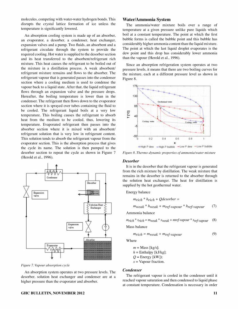
Since an absorption refrigeration system operates at two pressure levels, it means that there are two boiling curves for the mixture, each at a different pressure level as shown in Figure 8.
Figure 8. Thermo-dynamic properties of ammonia/water mixture
DesorberIt is in the desorber that the refrigerant vapour is generated
from the rich mixture by distillation. The weak mixture that remains in the desorber is returned to the absorber through the solution heat exchanger. The heat for distillation is supplied by the hot geothermal water.
Energy balance
mrich * hrich + Qdesorber =
mweak * hweak + mref-vapour * href-vapour (7)
Ammonia balance
mrich * xrich = mweak * xweak + mref-vapour * xref-vapour (8)
Mass balance
mrich = mweak + mref-vapour (9)
Where
m = Mass [kg/s]; h = Enthalpy [kJ/kg]; Q = Energy [kW]); x = Vapour fraction.
CondenserThe refrigerant vapour is cooled in the condenser until it
reached vapour saturation and then condensed to liquid phase at constant temperature. Condensation is necessary in order
• .. .. ..
12 GHC BULLETIN, NOVEMBER 2012
for the refrigerant to acquire the potential to extract heat from the evaporator. Cooling water is the medium that extracts heat from the refrigerant vapour.
Energy balance
Qcond = mref * (href-vapour – href-liq) = mcooling water (hcooling water-out – hcooling water-in) (10)
Expansion ValveThe high pressure refrigerant liquid from the condenser is
throttled to the evaporator pressure by the expansion valve. The liquid neither does work nor is there work done on it, therefore, this process is assumed to be isenthalpic.
href-in = href-out (11)
EvaporatorThe medium being chilled extracts heat from the
refrigerated space and carries this heat to the evaporator. The liquid refrigerant extracts this heat and in the process it evaporates. The chilled medium is cooled and returned back to the refrigerated space.
Energy balance
Qevap = mref * (href-vapour – href-lig) =mIce water * (hIcewater-in – hIce water-out) (12)
AbsorberThe refrigerant vapour is absorbed by the weak mixture to
form a rich mixture. In this process, latent heat of vaporisation of the refrigerant is released and must be extracted using cold water in order to achieve a high concentration of ammonia in the rich mixture.
Energy balance
mweak * hweak + mref-vapour * href-vapour = mrich * hrich + Qabsorber (13)
Ammonia balance
mweak * xweak + mref-vapour * xref-vapour = mrich * xrich (14)
Mass balance
mweak + mref-vapour = mrich (15)
PumpThe pump increases the pressure of the rich mixture from
the evaporator pressure to the condenser pressure. In the process, it does work on the rich mixture and hence increases its enthalpy.
hafter pump = hbefore pump + wpump (16)wpump = vbefore pump * (Phigh – Plow) / ηpump (17)
Where w = work v = specific volume (m3/kg) p = pressure η = efficiency (%)
Solution Heat ExchangerIn order to improve the coefficient of performance of the
absorption system the solution heat exchanger recovers some of the heat from the weak mixture leaving the desorber and transfers it to the rich mixture entering the desorber.
Energy balance
mrich-in * hrich-in + mweak-in * hweak-in = mrich-out * hrich-out + mweak-out * hweak-out (18)
Coefficient of Performance (COP)Thermal energy is supplied to the absorption refrigerator
in order to produce the refrigeration effect. The measure of the ability of the absorption machine to transform supplied thermal energy to refrigeration effect is called COP and given by the following equation.
(19)
rEsults and discussionThe processing of milk is energy dependent and large
quantity of heat is consumed during this exercise. At every stage of the processing, heat is either added or extracted from the milk in order to make milk safer for consumption or increase its shelf life.
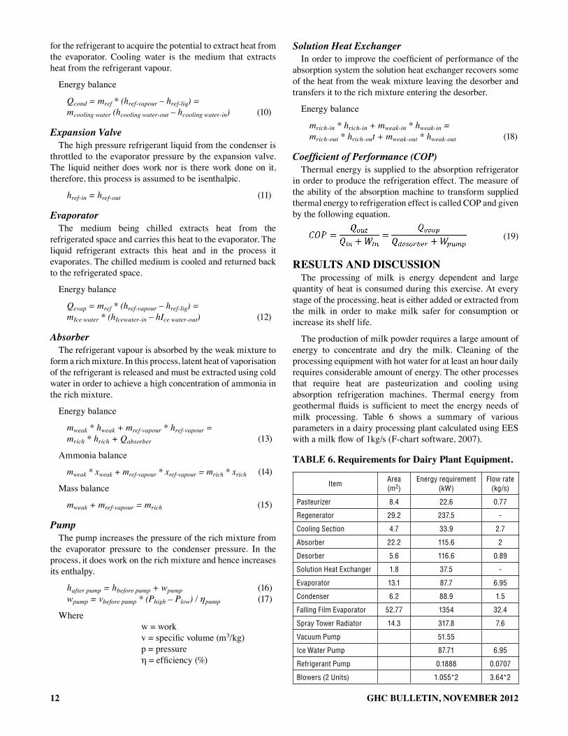
The production of milk powder requires a large amount of energy to concentrate and dry the milk. Cleaning of the processing equipment with hot water for at least an hour daily requires considerable amount of energy. The other processes that require heat are pasteurization and cooling using absorption refrigeration machines. Thermal energy from geothermal fluids is sufficient to meet the energy needs of milk processing. Table 6 shows a summary of various parameters in a dairy processing plant calculated using EES with a milk flow of 1kg/s (F-chart software, 2007).
tablE 6. requirements for dairy Plant Equipment.
ItemArea (m2)
Energy requirement (kW)
Flow rate (kg/s)
Pasteurizer 8.4 22.6 0.77
Regenerator 29.2 237.5 -
Cooling Section 4.7 33.9 2.7
Absorber 22.2 115.6 2
Desorber 5.6 116.6 0.89
Solution Heat Exchanger 1.8 37.5 -
Evaporator 13.1 87.7 6.95
Condenser 6.2 88.9 1.5
Falling Film Evaporator 52.77 1354 32.4
Spray Tower Radiator 14.3 317.8 7.6
Vacuum Pump 51.55
Ice Water Pump 87.71 6.95
Refrigerant Pump 0.1888 0.0707
Blowers (2 Units) 1.055*2 3.64*2

13GHC BULLETIN, NOVEMBER 2012
fluid milk ProcessingFluid milk refers to milk that has been processed for
consumption as a fresh product. The processing of fluid milk entails heating it to 76°C and holding it at this temperature for about 15 seconds to obtain an adequately pasteurised product. The pasteurised product is then cooled to ≤ 4°C before packaging or storage. An absorption chiller is used to provide ice water which is used to cool the milk as shown in Figure 9.
In fluid milk processing, pasteurization and cooling are the main processes involved. Thermal energy from hot water provides the necessary energy to achieve the objectives of these two processes.
Figure 9. Pasteurisation and absorption cooling processes
The energy consumption in the dairy industry depends on the amount of milk that is being processed. Therefore, the more milk there is to process, the more the energy required. This energy is transferred across heat exchangers either from the heating medium to the milk during pasteurization or from the milk to ice water during cooling. The heat exchange area depends on the quantity of thermal energy being transferred and the flow rate of the fluids exchanging the heat as shown in Figure 10.
Figure 10. Heat exchange area and energy requirements for pasteurization
Pasteurization requires that each droplet of milk should attain the pasteurization temperature and maintain that temperature for a certain period of time. This means that the heating medium which is in most cases hot water should be
sufficiently hot and have adequate flow rate to meet this requirement. The flow rate of the heating medium is therefore determined by the flow rate of the milk.
In the regenerator, no external heat is introduced into the system. The heat in the hot pasteurized milk is used to preheat the incoming cold milk. The amount of heat transferred in the regenerative section is very large and therefore, this is normally the biggest heat exchanger in dairy processing. 90-95% of the heat in the milk between the pasteurization and storage temperature is transferred at the regenerator.
Due to the pinch in the regenerator, the precooled milk is at a higher temperature than the storage temperature. It is necessary therefore to cool the milk to the storage temperature using ice water. Heat from the environment is conducted or gets infiltrated into the storage room and it must be removed so as to maintain the cold room at the storage temperature. Heat from other sources such as the storage containers, lighting, electrical appliances and people also finds its way into the storage room and should be removed or kept as low as possible.
The milk arriving at the processing plant from the farmers is usually not processed immediately because it should be de-aerated and the waiting period can be longer if there is backlog. To preserve this milk as it waits processing, it is cooled while in the storage silos.
The heat that should be removed from milk before processing, after processing and during storage constitutes the cooling load. Chilled water or ice water is the medium which is used to extract the cooling load from the milk and from the cold storage room. This means that the production of ice water is a continuous process even when there is no milk being processed in order to maintain the low temperature of the cold storage room as shown in Figure 11. In the processing of fluid milk, hot water is required both for pasteurization and to power the cooling process.
Figure 11. Hot water requirements and ice water production
The production of ice water or chilled water is a refrigeration process that involves extraction of heat from water at 3°C to about 0°C. The heat is removed by a refrigerant medium which extracts it from the water at the evaporator and rejects it at the condenser. In a vapour absorption system, an input of thermal energy at the desorber is required to drive the
.. "
\ ~-By
•
J
.. i , .. I I
D -
j [ •
I ,
I J .. .. • • .. .. .. .. .. .. ..
-"'

14 GHC BULLETIN, NOVEMBER 2012
refrigerant through the system. The thermal energy required depends on the cooling demand that needs to be met. Figure 12 illustrates the amount of energy required by the desorber in order to provide adequate refrigeration at the evaporator.
Figure 12. Energy requirements for adequate refrigeration
In order to meet the cooling demand of the dairy plant, the evaporator area should be large enough and the flow of the ice water adequate. The efficiency of the absorption refrigerator is determined by the ratio of cooling load to the energy input into the desorber and the refrigerant pump. In this design the COP of the absorption chiller was found to be 0.75.
The evaporator and the condenser are some of the heat exchangers in an absorption refrigeration machine. The other heat exchangers are the absorber, desorber or generator and the solution heat exchanger. To a large extent, the size of these devices depends on the refrigeration demand of the system which in turn depends on the milk being processed and the need to keep the cold room at a given temperature. On the other hand, milk processing has three heat exchangers namely the pasteurizer, regenerator and the cooling section. The size of these heat exchangers depends on the amount of milk being processed. The relationship between pasteurization heat exchange area and the chiller heat exchange area in relation to the milk being processed is shown in Figure 13.
Figure 13. Area of the heat exchangers in a dairy processing plant
It is clear from this diagram that the area of the chiller heat exchangers is lowest relative to that of the pasteurization heat exchangers when the milk flow rate is between 0.8 kg/s and 1.3 kg/s. This can therefore be assumed to be the optimum operating range for the system at which the investment cost is
lowest since the cost will depend on the size of the heat exchangers used.
milk PowderThe production of milk powder is the most energy intensive
dairy processing activity in terms of energy consumption per litre of milk processed. In the falling film evaporator, hot water at 70°C is used as the heat source and it is here that about 80% 0f the water that should be evaporated from the milk is removed. The resulting product is called concentrated milk and has a dry matter content of 45-55%. In the spray tower, atomized milk is dried by hot air. The air is heated in a coil by hot water or steam. The temperature of the drying air is 95°C while the temperature of the heating medium is 110°C as shown in Figure 14.
Figure 14. Falling film evaporator and spray tower
The quantity of milk to be dried depends entirely on the amount of energy available in the heating medium and the evaporation/drying area as shown in Figure 15. This energy is on the other hand determined by the temperature of the heating medium and its flow rate.
Figure 15. Milk powder energy and heat exchange area requirements
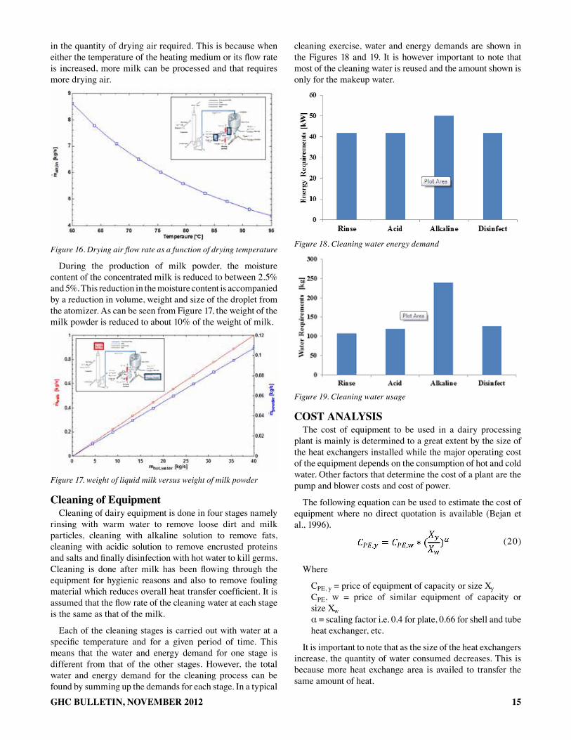
The air entering into the spray tower is at a constant temperature. Therefore, to ensure there is uniform drying of the milk while using a given quantity of heat, the air flow rate must be varied if the drying air temperature is to be varied as shown below in Figure 16.
The other factors that determine the flow rate of drying air are the temperature of the heating medium and its flow rate. An increase in any of these two factors results in an increase
I
J
-~;;r----::7: - ~¥)r ~
-r=~/
-••
• l •
• '.L,.~~" "" . " .. .. :: .. ", .. --
---j -
_. . --
.... 1_._ , -
" 'J"~-'--" -. . ' - --
15GHC BULLETIN, NOVEMBER 2012
in the quantity of drying air required. This is because when either the temperature of the heating medium or its flow rate is increased, more milk can be processed and that requires more drying air.
Figure 16. Drying air flow rate as a function of drying temperature
During the production of milk powder, the moisture content of the concentrated milk is reduced to between 2.5% and 5%. This reduction in the moisture content is accompanied by a reduction in volume, weight and size of the droplet from the atomizer. As can be seen from Figure 17, the weight of the milk powder is reduced to about 10% of the weight of milk.
Figure 17. weight of liquid milk versus weight of milk powder
cleaning of EquipmentCleaning of dairy equipment is done in four stages namely
rinsing with warm water to remove loose dirt and milk particles, cleaning with alkaline solution to remove fats, cleaning with acidic solution to remove encrusted proteins and salts and finally disinfection with hot water to kill germs. Cleaning is done after milk has been flowing through the equipment for hygienic reasons and also to remove fouling material which reduces overall heat transfer coefficient. It is assumed that the flow rate of the cleaning water at each stage is the same as that of the milk.
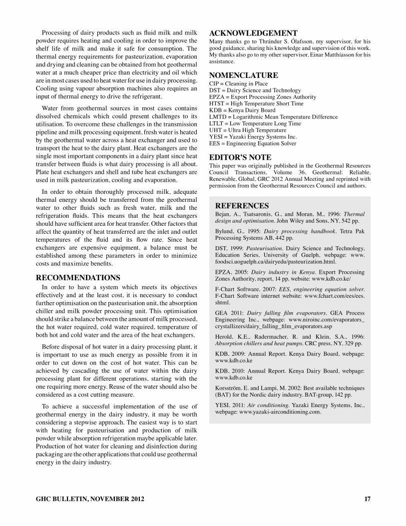
Each of the cleaning stages is carried out with water at a specific temperature and for a given period of time. This means that the water and energy demand for one stage is different from that of the other stages. However, the total water and energy demand for the cleaning process can be found by summing up the demands for each stage. In a typical
cleaning exercise, water and energy demands are shown in the Figures 18 and 19. It is however important to note that most of the cleaning water is reused and the amount shown is only for the makeup water.
Figure 18. Cleaning water energy demand
Figure 19. Cleaning water usage
cost analYsisThe cost of equipment to be used in a dairy processing
plant is mainly is determined to a great extent by the size of the heat exchangers installed while the major operating cost of the equipment depends on the consumption of hot and cold water. Other factors that determine the cost of a plant are the pump and blower costs and cost of power.
The following equation can be used to estimate the cost of equipment where no direct quotation is available (Bejan et al., 1996).
(20)
Where
CPE, y = price of equipment of capacity or size XyCPE, w = price of similar equipment of capacity or size Xwα = scaling factor i.e. 0.4 for plate, 0.66 for shell and tube heat exchanger, etc.
It is important to note that as the size of the heat exchangers increase, the quantity of water consumed decreases. This is because more heat exchange area is availed to transfer the same amount of heat.
60
o ~~--~'~~-----=70~--~7~6 -----:ILO----~"------~--~ Rinse Acid Alkaline DisinCect
r: .... poIr<ly .. tel
300 ~
... ,2
U
UI
... ! ~
UG
J IIA G.IM
11.2 tA~
0 , '10 15 :ZO 2~ 3IJ ", 0 ""-"-1M ~l

16 GHC BULLETIN, NOVEMBER 2012
Table 7 below shows the sizes of some of the dairy plant equipment, their sizes and cost.
tablE 7. cost of dairy Plant Equipment
Pasteurisation Area (m2)Rating (kW)
Cost (USD)
PasteurizerRegeneratorCooling sectionTotal
8.3429.184.71
2207364317577607
Absorption ChillersDesorberCondenserEvaporatorAbsorberSolution heat exchangerRefrigerant pumpIce water pumpPiping = 7% of heat exchangersTotal
5.596.14
13.0722.191.79
0.188887.71
294531305153730911931009001914
22644
Milk PowderFalling film evaporatorVacuum pumpRadiatorBlower (2 pieces)Total
52.77
14.2851.55
1.055*2
12948665306245
14164
Total investment cost 44415
The approximation method presented above in equation 20 uses a benchmark that does not originate from the dairy industry and hence care should be taken on absolute cost estimates. It is possible that the dairy industry requires specific stainless steel, surfacing methods or other finishing procedures that could have a significant effect on the estimates.
It is also important to note that this analysis does not include the cost of the wells, pipeline to the site of utilisation, wellheads and separators. The costs covered here are for those components which are in the circuit which is in direct contact with the heating and cooling medium or directly affected by these circuits. Therefore, circuits in which the milk only is flowing such as pipes and tanks are not included.
Before money is invested in any project, it is important to determine the total cost of the project over its entire life cycle. The costs included in the cost analysis of a dairy plant are the initial investment cost, the cost of electricity, the cost of hot water and the cost of cold water.
PriceHot Water = 0.45USD/m3 (21)PriceCold water = 0.28USD/m3 (22)Priceelec = 0.11USD/kWh (23)
Water consumption accounts for the largest annual operating cost. Hot water is used for pasteurization, concentrating and drying the milk, evaporating the refrigerant in the absorption chiller and cleaning while cold water is used mainly for cooling the refrigerant fluids and for cleaning. The cost of water depends on the price of water and the water consumption rate. In the case of hot water it is assumed that between 50% and 90% of the water is recycled at various
stages of consumption because it still contains some useable energy, and therefore, the cost of hot water is mainly for makeup water. Dairy processing operations are also assumed to be carried out for 350 days in a year.
costwater = mwater / ρwater * Pricewater * 3600 * hr/day * 350 (24)costelec = powerequip * hr * priceelec (25)
Where
ρ = density of water
The present value of the plant after a given period of time is given by
(26)
Where
PO = present valueFa = constant annual costρ = rate of returnn = life cycle of the project.hr = operation time per day in hours.
For this dairy plant, the operating cost for the first year is shown in Table 8.
tablE 8. annual operating cost of a dairy Processing Plant
ItemWater
consumption (m3)
Electricity consumption (USD/kWh)
Annual Running cost
(USD)
Fluid milkHot waterCold waterRefrigerant pumpWater pump
849923594
707328478
32246606
8036133
Milk powderblowerVacuum pumpHot water 20152
738.436082
8239699068
CleaningCleaning water 2097 936
ToTal 54342 366006 60098
conclusionThere are many energy sources available in the world
today. The conventional sources such as fossil fuels are quickly getting depleted and release large quantity of pollutants into the atmosphere after combustion. Others such as hydropower have been exploited almost to the limit and cannot meet the growing energy demand. However, other renewable energy resources such as geothermal are relatively underdeveloped and underutilized. With the recent focus and growth in geothermal technology, a lot of emphasis is being put in the utilisation of geothermal energy both for electricity generation and direct uses. Direct use applications utilize the waste heat in the geothermal water before it is disposed.
17GHC BULLETIN, NOVEMBER 2012
Processing of dairy products such as fluid milk and milk powder requires heating and cooling in order to improve the shelf life of milk and make it safe for consumption. The thermal energy requirements for pasteurization, evaporation and drying and cleaning can be obtained from hot geothermal water at a much cheaper price than electricity and oil which are in most cases used to heat water for use in dairy processing. Cooling using vapour absorption machines also requires an input of thermal energy to drive the refrigerant.
Water from geothermal sources in most cases contains dissolved chemicals which could present challenges to its utilisation. To overcome these challenges in the transmission pipeline and milk processing equipment, fresh water is heated by the geothermal water across a heat exchanger and used to transport the heat to the dairy plant. Heat exchangers are the single most important components in a dairy plant since heat transfer between fluids is what dairy processing is all about. Plate heat exchangers and shell and tube heat exchangers are used in milk pasteurization, cooling and evaporation.
In order to obtain thoroughly processed milk, adequate thermal energy should be transferred from the geothermal water to other fluids such as fresh water, milk and the refrigeration fluids. This means that the heat exchangers should have sufficient area for heat transfer. Other factors that affect the quantity of heat transferred are the inlet and outlet temperatures of the fluid and its flow rate. Since heat exchangers are expensive equipment, a balance must be established among these parameters in order to minimize costs and maximize benefits.
rEcommEndationsIn order to have a system which meets its objectives
effectively and at the least cost, it is necessary to conduct further optimisation on the pasteurisation unit, the absorption chiller and milk powder processing unit. This optimisation should strike a balance between the amount of milk processed, the hot water required, cold water required, temperature of both hot and cold water and the area of the heat exchangers.
Before disposal of hot water in a dairy processing plant, it is important to use as much energy as possible from it in order to cut down on the cost of hot water. This can be achieved by cascading the use of water within the dairy processing plant for different operations, starting with the one requiring more energy. Reuse of the water should also be considered as a cost cutting measure.
To achieve a successful implementation of the use of geothermal energy in the dairy industry, it may be worth considering a stepwise approach. The easiest way is to start with heating for pasteurisation and production of milk powder while absorption refrigeration maybe applicable later. Production of hot water for cleaning and disinfection during packaging are the other applications that could use geothermal energy in the dairy industry.
acknoWlEdGEmEntMany thanks go to Thrándur S. Ólafsson, my supervisor, for his good guidance, sharing his knowledge and supervision of this work. My thanks also go to my other supervisor, Einar Matthíasson for his assistance.
nomEnclaturECIP = Cleaning in PlaceDST = Dairy Science and TechnologyEPZA = Export Processing Zones AuthorityHTST = High Temperature Short TimeKDB = Kenya Dairy BoardLMTD = Logarithmic Mean Temperature DifferenceLTLT = Low Temperature Long TimeUHT = Ultra High TemperatureYESI = Yazaki Energy Systems Inc.EES = Engineering Equation Solver
Editor’s notEThis paper was originally published in the Geothermal Resources Council Transactions, Volume 36, Geothermal: Reliable, Renewable, Global, GRC 2012 Annual Meeting and reprinted with permission from the Geothermal Resources Council and authors.
rEfErEncEsBejan, A., Tsatsaronis, G., and Moran, M., 1996: Thermal design and optimisation. John Wiley and Sons, NY, 542 pp.
Bylund, G., 1995: Dairy processing handbook. Tetra Pak Processing Systems AB, 442 pp.
DST, 1999: Pasteurisation. Dairy Science and Technology, Education Series, University of Guelph, webpage: www.foodsci.uoguelph.ca/dairyedu/pasteurization.html.
EPZA, 2005: Dairy industry in Kenya. Export Processing Zones Authority, report, 14 pp, website: www.kdb.co.ke/
F-Chart Software, 2007: EES, engineering equation solver. F-Chart Software internet website: www.fchart.com/ees/ees.shtml.
GEA 2011: Dairy falling film evaporators. GEA Process Engineering Inc., webpage: www.niroinc.com/evaporators_crystallizers/dairy_falling_film_evaporators.asp
Herold, K.E., Radermacher, R. and Klein, S.A., 1996: Absorption chillers and heat pumps. CRC press, NY, 329 pp.
KDB, 2009: Annual Report. Kenya Dairy Board, webpage: www.kdb.co.ke
KDB, 2010: Annual Report. Kenya Dairy Board, webpage: www.kdb.co.ke
Korsström, E. and Lampi, M. 2002: Best available techniques (BAT) for the Nordic dairy industry. BAT-group, 142 pp.
YESI, 2011: Air conditioning. Yazaki Energy Systems, Inc., webpage: www.yazaki-airconditioning.com.