user guide optidrive vtc - invertek · pdf fileuser guide optidrive vtc ... basic parameters...
TRANSCRIPT
User Guide
Optidrive VTC
Variable Torque Control AC Variable Speed Drive 1.5 – 160kW (2 – 250HP)
Installation and operating instructions
Optidrive VTC – User Guide
2 www.invertek.co.uk
Declaration of Conformity:
Invertek Drives Ltd hereby states that the Optidrive VTC product range conforms to the relevant safety provisions of the Low Voltage Directive 2006/95/EC and the EMC Directive 2004/108/EC and has been designed and manufactured in accordance with the following harmonised European standards:
EN 61800-5-1: 2003 Adjustable speed electrical power drive systems. Safety requirements. Electrical, thermal and energy.
EN 61800-3 2nd
Ed: 2004 Adjustable speed electrical power drive systems. EMC requirements and specific test methods
EN 55011: 2007 Limits and Methods of measurement of radio disturbance characteristics of industrial, scientific and medical (ISM) radio-frequency equipment (EMC)
EN60529 : 1992 Specifications for degrees of protection provided by enclosures
Electromagnetic Compatibility
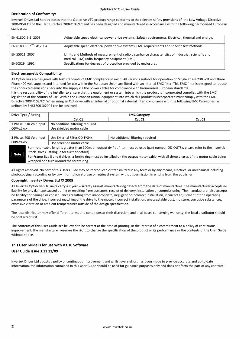
All Optidrives are designed with high standards of EMC compliance in mind. All versions suitable for operation on Single Phase 230 volt and Three Phase 400 volt supplies and intended for use within the European Union are fitted with an internal EMC filter. This EMC filter is designed to reduce the conducted emissions back into the supply via the power cables for compliance with harmonised European standards. It is the responsibility of the installer to ensure that the equipment or system into which the product is incorporated complies with the EMC legislation of the country of use. Within the European Union, equipment into which this product is incorporated must comply with the EMC Directive 2004/108/EC. When using an Optidrive with an internal or optional external filter, compliance with the following EMC Categories, as defined by EN61800-3:2004 can be achieved:
Drive Type / Rating EMC Category
Cat C1 Cat C2 Cat C3
1 Phase, 230 Volt Input ODV-x2xxx
No additional filtering required Use shielded motor cable
3 Phase, 400 Volt Input ODV-x4xxx
Use External Filter OD-Fx34x No additional filtering required
Use screened motor cable
Note
For motor cable lengths greater than 100m, an output dv / dt filter must be used (part number OD-OUTFx, please refer to the Invertek Stock Drives Catalogue for further details)
For Frame Size 5 and 6 drives, a ferrite ring must be installed on the output motor cable, with all three phases of the motor cable being wrapped one turn around the ferrite ring.
All rights reserved. No part of this User Guide may be reproduced or transmitted in any form or by any means, electrical or mechanical including photocopying, recording or by any information storage or retrieval system without permission in writing from the publisher.
Copyright Invertek Drives Ltd © 2009
All Invertek Optidrive VTC units carry a 2 year warranty against manufacturing defects from the date of manufacture. The manufacturer accepts no liability for any damage caused during or resulting from transport, receipt of delivery, installation or commissioning. The manufacturer also accepts no liability for damage or consequences resulting from inappropriate, negligent or incorrect installation, incorrect adjustment of the operating parameters of the drive, incorrect matching of the drive to the motor, incorrect installation, unacceptable dust, moisture, corrosive substances, excessive vibration or ambient temperatures outside of the design specification. The local distributor may offer different terms and conditions at their discretion, and in all cases concerning warranty, the local distributor should be contacted first. The contents of this User Guide are believed to be correct at the time of printing. In the interest of a commitment to a policy of continuous improvement, the manufacturer reserves the right to change the specification of the product or its performance or the contents of the User Guide without notice.
This User Guide is for use with V3.10 Software.
User Guide Issue 3.11 11/09
Invertek Drives Ltd adopts a policy of continuous improvement and whilst every effort has been made to provide accurate and up to date information, the information contained in this User Guide should be used for guidance purposes only and does not form the part of any contract.
Optidrive VTC – User Guide
www.invertek.co.uk 3
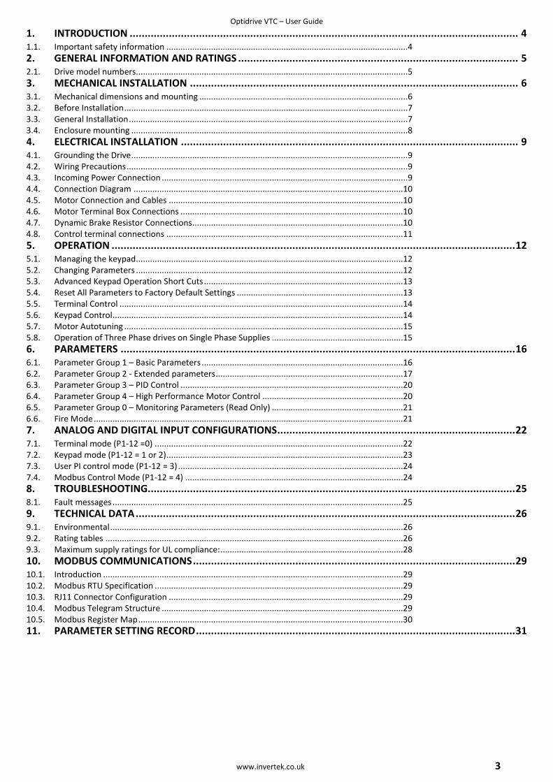
1. INTRODUCTION ................................................................................................................................. 4
1.1. Important safety information .......................................................................................................4 2. GENERAL INFORMATION AND RATINGS ............................................................................................. 5
2.1. Drive model numbers....................................................................................................................5 3. MECHANICAL INSTALLATION ............................................................................................................. 6
3.1. Mechanical dimensions and mounting .........................................................................................6 3.2. Before Installation .........................................................................................................................7 3.3. General Installation .......................................................................................................................7 3.4. Enclosure mounting ......................................................................................................................8 4. ELECTRICAL INSTALLATION ................................................................................................................ 9
4.1. Grounding the Drive ......................................................................................................................9 4.2. Wiring Precautions ........................................................................................................................9 4.3. Incoming Power Connection .........................................................................................................9 4.4. Connection Diagram ...................................................................................................................10 4.5. Motor Connection and Cables ....................................................................................................10 4.6. Motor Terminal Box Connections ...............................................................................................10 4.7. Dynamic Brake Resistor Connections..........................................................................................10 4.8. Control terminal connections .....................................................................................................11 5. OPERATION ...................................................................................................................................... 12
5.1. Managing the keypad..................................................................................................................12 5.2. Changing Parameters ..................................................................................................................12 5.3. Advanced Keypad Operation Short Cuts .....................................................................................13 5.4. Reset All Parameters to Factory Default Settings .......................................................................13 5.5. Terminal Control .........................................................................................................................14 5.6. Keypad Control ............................................................................................................................14 5.7. Motor Autotuning .......................................................................................................................15 5.8. Operation of Three Phase drives on Single Phase Supplies ........................................................15 6. PARAMETERS ................................................................................................................................... 16
6.1. Parameter Group 1 – Basic Parameters ......................................................................................16 6.2. Parameter Group 2 - Extended parameters ................................................................................17 6.3. Parameter Group 3 – PID Control ...............................................................................................20 6.4. Parameter Group 4 – High Performance Motor Control ............................................................20 6.5. Parameter Group 0 – Monitoring Parameters (Read Only) ........................................................21 6.6. Fire Mode ....................................................................................................................................21 7. ANALOG AND DIGITAL INPUT CONFIGURATIONS ............................................................................... 22
7.1. Terminal mode (P1-12 =0) ..........................................................................................................22 7.2. Keypad mode (P1-12 = 1 or 2) .....................................................................................................23 7.3. User PI control mode (P1-12 = 3) ................................................................................................24 7.4. Modbus Control Mode (P1-12 = 4) .............................................................................................24 8. TROUBLESHOOTING.......................................................................................................................... 25
8.1. Fault messages ............................................................................................................................25 9. TECHNICAL DATA .............................................................................................................................. 26
9.1. Environmental .............................................................................................................................26 9.2. Rating tables ...............................................................................................................................26 9.3. Maximum supply ratings for UL compliance: ..............................................................................28 10. MODBUS COMMUNICATIONS ........................................................................................................... 29
10.1. Introduction ................................................................................................................................29 10.2. Modbus RTU Specification ..........................................................................................................29 10.3. RJ11 Connector Configuration ....................................................................................................29 10.4. Modbus Telegram Structure .......................................................................................................29 10.5. Modbus Register Map .................................................................................................................30 11. PARAMETER SETTING RECORD .......................................................................................................... 31

Optidrive VTC – User Guide
4 www.invertek.co.uk
1. Introduction
1.1. Important safety information
Please read the IMPORTANT SAFETY INFORMATION below, and all Warning and Caution information elsewhere.
Indicates a potentially hazardous situation which, if not avoided, could result in injury or death.
Indicates a potentially hazardous situation which, if not avoided, could result in damage to property.
This variable speed drive product (Optidrive) is intended for professional incorporation into complete equipment or systems as part of a fixed installation. If installed incorrectly it may present a safety hazard. The Optidrive uses high voltages and currents, carries a high level of stored electrical energy, and is used to control mechanical plant that may cause injury. Close attention is required to system design and electrical installation to avoid hazards in either normal operation or in the event of equipment malfunction.
System design, installation, commissioning and maintenance must be carried out only by personnel who have the necessary training and experience. They must carefully read this safety information and the instructions in this Guide and follow all information regarding transport, storage, installation and use of the Optidrive, including the specified environmental limitations.
The level of integrity offered by the Optidrive control functions – for example stop/start, forward/reverse and maximum speed, is not sufficient for use in safety-critical applications without independent channels of protection. All applications where malfunction could cause injury or loss of life must be subject to a risk assessment and further protection provided where needed.
Within the European Union, all machinery in which this product is used must comply with Directive 98/37/EC, Safety of Machinery. In particular, the machine manufacturer is responsible for providing a main switch and ensuring the electrical equipment complies with EN60204-1.
The driven motor can start at power up if the enable input signal is present.
The STOP function does not remove potentially lethal high voltages. ISOLATE the drive and wait 10 minutes before starting any work on it.
Electric shock hazard! Disconnect and ISOLATE the Optidrive before attempting any work on it. High voltages are present at the terminals and within the drive for up to 10 minutes after disconnection of the electrical supply.
Where supply to the drive is through a plug and socket connector, do not disconnect until 10 minutes have elapsed after turning off the supply.
Ensure correct earthing connections. The earth cable must be sufficient to carry the maximum supply fault current which normally will be limited by the fuses or MCB. Suitably rated fuses or MCB should be fitted in the mains supply to the drive.
Flammable material should not be placed close to the drive
Parameter P1-01 can be set to operate the motor at up to 120,000 rpm, hence use this parameter with care.
If it is desired to operate the drive at any frequency/speed above the rated speed (P1-09/ P1-10) of the motor, consult the manufacturers of the motor and the driven machine about suitability for over-speed operation.
Carefully inspect the Optidrive before installation to ensure it is undamaged
The Optidrive VTC has an Ingress Protection rating of IP20 or IP)) depending on the model. Units should be installed in a suitable enclosure.
Optidrives are intended for indoor use only.
Do not perform and flash test or voltage withstand test on the Optidrive. Any electrical measurements required should be carried out with the Optidrive disconnected.
The entry of conductive or flammable foreign bodies should be prevented
Relative humidity must be less than 95% (non-condensing).
Ensure that the supply voltage, frequency and no. of phases (1 or 3 phase) correspond to the rating of the Optidrive as delivered.
Never connect the mains power supply to the Output terminals U, V, W.
Do not install any type of automatic switchgear between the drive and the motor
Wherever control cabling is close to power cabling, maintain a minimum separation of 100 mm and arrange crossings at 90 degrees Ensure that all terminals are tightened to the appropriate torque setting
Optidrive VTC – User Guide
www.invertek.co.uk 5
2. General Information and Ratings
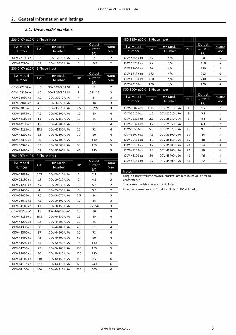
2.1. Drive model numbers
480-525V ±10% - 3 Phase Input
kW Model Number
kW HP Model Number
HP Output Current
(A)
Frame Size
ODV-55550-xx 55 N/A 90 5
ODV-55750-xx 75 N/A 110 5
ODV-55900-xx 90 N/A 150 5
ODV-65132-xx 132 N/A 202 6
ODV-65160-xx 160 N/A 240 6
ODV-65200-xx 200 N/A 270 6
500-600V ±10% - 3 Phase Input
kW Model Number
kW HP Model Number
HP Output Current
(A)
Frame Size
ODV-25075-xx 0.75 ODV-25010-USA 1 1.7 2
ODV-25150-xx 1.5 ODV-25020-USA 2 3.1 2
ODV-25220-xx 2.2 ODV-25030-USA 3 4.1 2
ODV-25370-xx 3.7 ODV-25050-USA 5 6.1 2
ODV-25550-xx 5.5 ODV-25075-USA 7.5 9.5 2
ODV-35075-xx 7.5 ODV-35100-USA 10 14 3
ODV-35110-xx 11 ODV-35150-USA 15 18 3
ODV-35150-xx 15 ODV-35200-USA 20 24 3
ODV-45220-xx 22 ODV-45300-USA 30 39 4
ODV-45300-xx 30 ODV-45400-USA 40 46 4
ODV-45450-xx 45 ODV-45600-USA 60 62 4
Notes Output current values shown in brackets are maximum values for UL conformance.
* Indicates models that are not UL listed
Input line choke must be fitted for all size 2 500 volt units
200-240V ±10% - 1 Phase Input
kW Model Number
kW HP Model Number
HP Output Current
(A)
Frame Size
ODV-22150-xx 1.5 ODV-12020-USA 2 7 2
ODV-22220-xx 2.2 ODV-12030-USA 3 10.5 2
200-240V ±10% - 3 Phase Input
kW Model Number
kW HP Model Number
HP Output Current
(A)
Frame Size
ODV3-22150-xx 1.5 ODV3-22020-USA 2 7 2
ODV3-22220-xx 2.2 ODV3-22030-USA 3 10.5 (* 9) 2
ODV-32030-xx 3.0 ODV-32040-USA 4 14 3
ODV-32040-xx 4.0 ODV-32050-USA 5 18 3
ODV-32055-xx 5.5 ODV-32075-USA 7.5 25 (*24) 3
ODV-42075-xx 7.5 ODV-42100-USA 10 39 4
ODV-42110-xx 11 ODV-42150-USA 15 46 4
ODV-42150-xx 15 ODV-42200-USA 20 61 4
ODV-42185-xx 18.5 ODV-42250-USA 25 72 4
ODV-42220-xx 22 ODV-42300-USA 30 90 4
ODV-52300-xx 30 ODV-52400-USA 40 110 5
ODV-52370-xx 37 ODV-52500-USA 50 150 5
ODV-52450-xx 45 ODV-52600-USA 60 180 5
380-480V ±10% - 3 Phase Input
kW Model Number
kW HP Model Number
HP Output Current
(A)
Frame Size
ODV-24075-xx 0.75 ODV-24010-USA 1 2.2 2
ODV-24150-xx 1.5 ODV-24020-USA 2 4.1 2
ODV-24220-xx 2.2 ODV-24030-USA 3 5.8 2
ODV-24400-xx 4 ODV-24050-USA 5 9.5 2
ODV-34055-xx 5.5 ODV-34075-USA 7.5 14 3
ODV-34075-xx 7.5 ODV-34100-USA 10 18 3
ODV-34110-xx 11 ODV-34150-USA 15 25 (24) 3
ODV-34150-xx* 15 ODV-34200-USA* 20 30 3
ODV-44185-xx 18.5 ODV-44250-USA 25 39 4
ODV-44220-xx 22 ODV-44300-USA 30 46 4
ODV-44300-xx 30 ODV-44400-USA 40 61 4
ODV-44370-xx 37 ODV-44500-USA 50 72 4
ODV-44450-xx 45 ODV-44600-USA 60 90 4
ODV-54550-xx 55 ODV-54750-USA 75 110 5
ODV-54750-xx 75 ODV-54100-USA 100 150 5
ODV-54090-xx 90 ODV-54120-USA 120 180 5
ODV-64110-xx 110 ODV-64150-USA 150 202 6
ODV-64132-xx 132 ODV-64175-USA 175 240 6
ODV-64160-xx 160 ODV-64210-USA 210 300 6

Optidrive VTC – User Guide
6 www.invertek.co.uk
3. Mechanical Installation
3.1. Mechanical dimensions and mounting
3.1.1. Frame Size 2
Overall Dimensions
Height 260mm
Width 100mm
Depth 175mm
A 210mm
B 92mm
Incoming Power Terminals C 25mm
Help Card
Keypad & Display – See Section 0 on page 12 Footprint View
RJ11 Connector – See Section
Infra Red Interface Weight : 2.6Kg
Control Terminals – See Section on page 10
Motor & Brake Resistor Connection Terminals
Fixings : 2 x M4 Keyhole slots
Power Terminals Torque Setting : 1Nm
3.1.2. Frame Size 3
Overall Dimensions
Height 260mm
Width 171mm
Depth 175mm
A 210mm
B 163mm
Incoming Power Terminals C 25mm
Help Card
Keypad & Display – See Section 0 on page 12 Footprint View
RJ11 Connector – See Section
Infra Red Interface Weight : 5.3Kg
Control Terminals – See Section on page 10
Motor & Brake Resistor Connection Terminals
Fixings : 4 x M4 Keyhole slots
Power Terminals Torque Setting : 1Nm
3.1.3. Frame Size 4
Overall Dimensions
Height 520mm
Width 340mm
Depth 220mm
A 420mm
B 320mm
Incoming Power Terminals C 50mm
Help Card
Keypad & Display – See Section 0 on page 12 Footprint View
RJ11 Connector – See Section
Infra Red Interface Weight : 28Kg
Control Terminals – See Section on page 10
Motor & Brake Resistor Connection Terminals
Fixings : 4 x M8 Keyhole slots
Power Terminals Torque Setting : 4Nm
Optidrive VTC – User Guide
www.invertek.co.uk 7
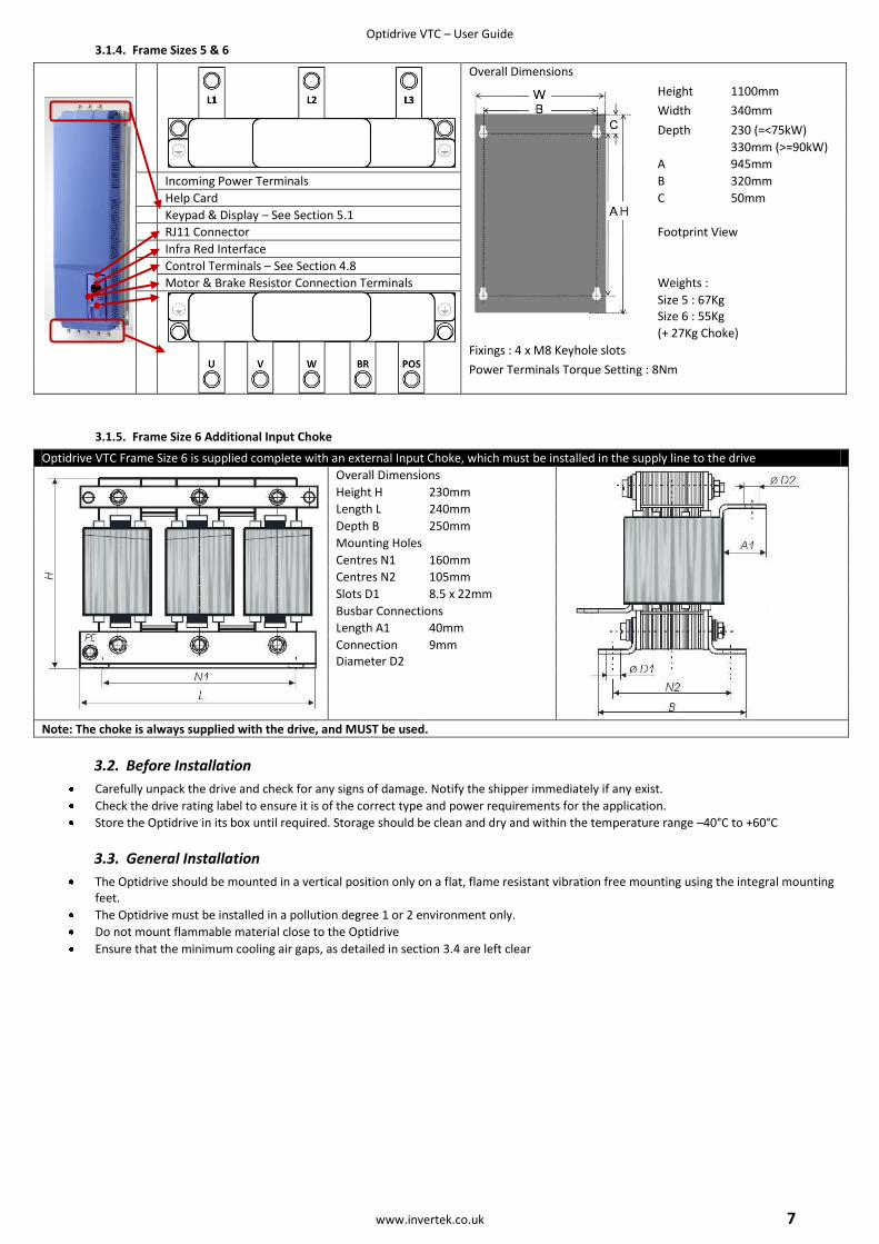
3.1.4. Frame Sizes 5 & 6
Overall Dimensions
Height 1100mm
Width 340mm
Depth 230 (=<75kW)
330mm (>=90kW)
A 945mm
Incoming Power Terminals B 320mm
Help Card C 50mm
Keypad & Display – See Section 5.1
RJ11 Connector Footprint View
Infra Red Interface
Control Terminals – See Section 4.8
Motor & Brake Resistor Connection Terminals Weights :
Size 5 : 67Kg Size 6 : 55Kg
(+ 27Kg Choke)
Fixings : 4 x M8 Keyhole slots
Power Terminals Torque Setting : 8Nm
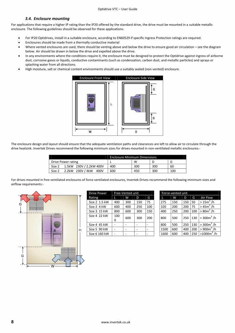
3.1.5. Frame Size 6 Additional Input Choke
Optidrive VTC Frame Size 6 is supplied complete with an external Input Choke, which must be installed in the supply line to the drive
Overall Dimensions
Height H 230mm
Length L 240mm
Depth B 250mm
Mounting Holes
Centres N1 160mm
Centres N2 105mm
Slots D1 8.5 x 22mm
Busbar Connections
Length A1 40mm
Connection Diameter D2
9mm
Note: The choke is always supplied with the drive, and MUST be used.
3.2. Before Installation
Carefully unpack the drive and check for any signs of damage. Notify the shipper immediately if any exist.
Check the drive rating label to ensure it is of the correct type and power requirements for the application.
Store the Optidrive in its box until required. Storage should be clean and dry and within the temperature range –40°C to +60°C
3.3. General Installation
The Optidrive should be mounted in a vertical position only on a flat, flame resistant vibration free mounting using the integral mounting feet.
The Optidrive must be installed in a pollution degree 1 or 2 environment only.
Do not mount flammable material close to the Optidrive
Ensure that the minimum cooling air gaps, as detailed in section 3.4 are left clear
Optidrive VTC – User Guide
8 www.invertek.co.uk
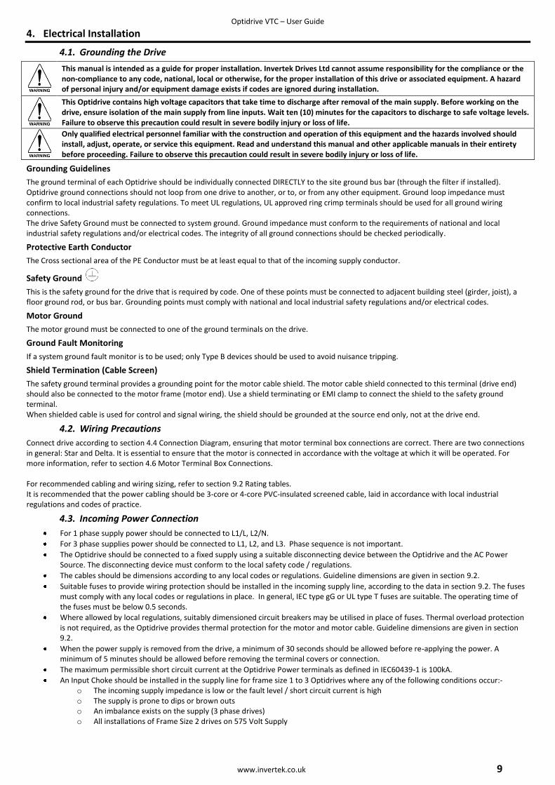
3.4. Enclosure mounting
For applications that require a higher IP rating than the IP20 offered by the standard drive, the drive must be mounted in a suitable metallic enclosure. The following guidelines should be observed for these applications:
For IP20 Optidrives, install in a suitable enclosure, according to EN60529 if specific Ingress Protection ratings are required.
Enclosures should be made from a thermally conductive material
Where vented enclosures are used, there should be venting above and below the drive to ensure good air circulation – see the diagram below. Air should be drawn in below the drive and expelled above the drive.
In any environments where the conditions require it, the enclosure must be designed to protect the Optidrive against ingress of airborne dust, corrosive gases or liquids, conductive contaminants (such as condensation, carbon dust, and metallic particles) and sprays or splashing water from all directions.
High moisture, salt or chemical content environments should use a suitably sealed (non-vented) enclosure.
Enclosure Front View Enclosure Side View
The enclosure design and layout should ensure that the adequate ventilation paths and clearances are left to allow air to circulate through the drive heatsink. Invertek Drives recommend the following minimum sizes for drives mounted in non-ventilated metallic enclosures:-
Enclosure Minimum Dimensions
Drive Power rating L W D G
Size 2 1.5kW 230V / 2.2kW 400V 400 300 300 60
Size 2 2.2kW 230V / 4kW 400V 600 450 300 100
For drives mounted in free ventilated enclosures of force ventilated enclosures, Invertek Drives recommend the following minimum sizes and airflow requirements:-
Drive Power Rating
Free-Vented unit Force-vented unit
L W D G L W D G Air Flow
Size 2 1.5 kW 400 300 150 75 275 150 150 50 > 15m3 /h
Size 2 4 kW 600 400 250 100 320 200 200 75 > 45m3 /h
Size 3 15 kW 800 600 300 150 400 250 200 100 > 80m3 /h
Size 4 22 kW 1000
600 300 200
800 500 250 130 > 300m3 /h
Size 4 45 kW - - - - 800 500 250 130 > 300m3 /h
Size 5 90 kW - - - - 1500 600 400 200 > 900m3 /h
Size 6 160 kW - - - - 1600 600 400 250 >1000m3 /h
Optidrive VTC – User Guide
www.invertek.co.uk 9
4. Electrical Installation
4.1. Grounding the Drive
This manual is intended as a guide for proper installation. Invertek Drives Ltd cannot assume responsibility for the compliance or the non-compliance to any code, national, local or otherwise, for the proper installation of this drive or associated equipment. A hazard of personal injury and/or equipment damage exists if codes are ignored during installation.
This Optidrive contains high voltage capacitors that take time to discharge after removal of the main supply. Before working on the drive, ensure isolation of the main supply from line inputs. Wait ten (10) minutes for the capacitors to discharge to safe voltage levels. Failure to observe this precaution could result in severe bodily injury or loss of life.
Only qualified electrical personnel familiar with the construction and operation of this equipment and the hazards involved should install, adjust, operate, or service this equipment. Read and understand this manual and other applicable manuals in their entirety before proceeding. Failure to observe this precaution could result in severe bodily injury or loss of life.
Grounding Guidelines
The ground terminal of each Optidrive should be individually connected DIRECTLY to the site ground bus bar (through the filter if installed). Optidrive ground connections should not loop from one drive to another, or to, or from any other equipment. Ground loop impedance must confirm to local industrial safety regulations. To meet UL regulations, UL approved ring crimp terminals should be used for all ground wiring connections. The drive Safety Ground must be connected to system ground. Ground impedance must conform to the requirements of national and local industrial safety regulations and/or electrical codes. The integrity of all ground connections should be checked periodically.
Protective Earth Conductor
The Cross sectional area of the PE Conductor must be at least equal to that of the incoming supply conductor.
Safety Ground
This is the safety ground for the drive that is required by code. One of these points must be connected to adjacent building steel (girder, joist), a floor ground rod, or bus bar. Grounding points must comply with national and local industrial safety regulations and/or electrical codes.
Motor Ground
The motor ground must be connected to one of the ground terminals on the drive.
Ground Fault Monitoring
If a system ground fault monitor is to be used; only Type B devices should be used to avoid nuisance tripping.
Shield Termination (Cable Screen)
The safety ground terminal provides a grounding point for the motor cable shield. The motor cable shield connected to this terminal (drive end) should also be connected to the motor frame (motor end). Use a shield terminating or EMI clamp to connect the shield to the safety ground terminal. When shielded cable is used for control and signal wiring, the shield should be grounded at the source end only, not at the drive end.
4.2. Wiring Precautions
Connect drive according to section 4.4 Connection Diagram, ensuring that motor terminal box connections are correct. There are two connections in general: Star and Delta. It is essential to ensure that the motor is connected in accordance with the voltage at which it will be operated. For more information, refer to section 4.6 Motor Terminal Box Connections. For recommended cabling and wiring sizing, refer to section 9.2 Rating tables. It is recommended that the power cabling should be 3-core or 4-core PVC-insulated screened cable, laid in accordance with local industrial regulations and codes of practice.
4.3. Incoming Power Connection
For 1 phase supply power should be connected to L1/L, L2/N.
For 3 phase supplies power should be connected to L1, L2, and L3. Phase sequence is not important.
The Optidrive should be connected to a fixed supply using a suitable disconnecting device between the Optidrive and the AC Power Source. The disconnecting device must conform to the local safety code / regulations.
The cables should be dimensions according to any local codes or regulations. Guideline dimensions are given in section 9.2.
Suitable fuses to provide wiring protection should be installed in the incoming supply line, according to the data in section 9.2. The fuses must comply with any local codes or regulations in place. In general, IEC type gG or UL type T fuses are suitable. The operating time of the fuses must be below 0.5 seconds.
Where allowed by local regulations, suitably dimensioned circuit breakers may be utilised in place of fuses. Thermal overload protection is not required, as the Optidrive provides thermal protection for the motor and motor cable. Guideline dimensions are given in section 9.2.
When the power supply is removed from the drive, a minimum of 30 seconds should be allowed before re-applying the power. A minimum of 5 minutes should be allowed before removing the terminal covers or connection.
The maximum permissible short circuit current at the Optidrive Power terminals as defined in IEC60439-1 is 100kA.
An Input Choke should be installed in the supply line for frame size 1 to 3 Optidrives where any of the following conditions occur:- o The incoming supply impedance is low or the fault level / short circuit current is high o The supply is prone to dips or brown outs o An imbalance exists on the supply (3 phase drives) o All installations of Frame Size 2 drives on 575 Volt Supply
Optidrive VTC – User Guide
10 www.invertek.co.uk
In all other installations, an input choke is recommended to ensure protection of the drive against power supply faults. The recommended chokes can be found in the Invertek Stock Drives Catalogue
For compliance with CE and C Tick EMC requirements, a symmetrical shielded cable is recommended.
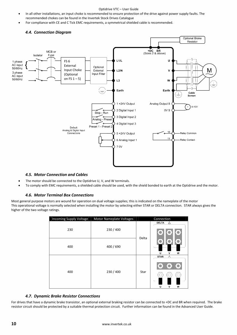
4.4. Connection Diagram
4.5. Motor Connection and Cables
The motor should be connected to the Optidrive U, V, and W terminals.
To comply with EMC requirements, a shielded cable should be used, with the shield bonded to earth at the Optidrive and the motor.
4.6. Motor Terminal Box Connections
Most general purpose motors are wound for operation on dual voltage supplies; this is indicated on the nameplate of the motor This operational voltage is normally selected when installing the motor by selecting either STAR or DELTA connection. STAR always gives the higher of the two voltage ratings.
Incoming Supply Voltage Motor Nameplate Voltages Connection
230 230 / 400
Delta
400 400 / 690
400 230 / 400 Star
4.7. Dynamic Brake Resistor Connections
For drives that have a dynamic brake transistor, an optional external braking resistor can be connected to +DC and BR when required. The brake resistor circuit should be protected by a suitable thermal protection circuit. Further information can be found in the Advanced User Guide.
FS 6 External Input Choke (Optional on FS 1 – 5)
Optidrive VTC – User Guide
www.invertek.co.uk 11
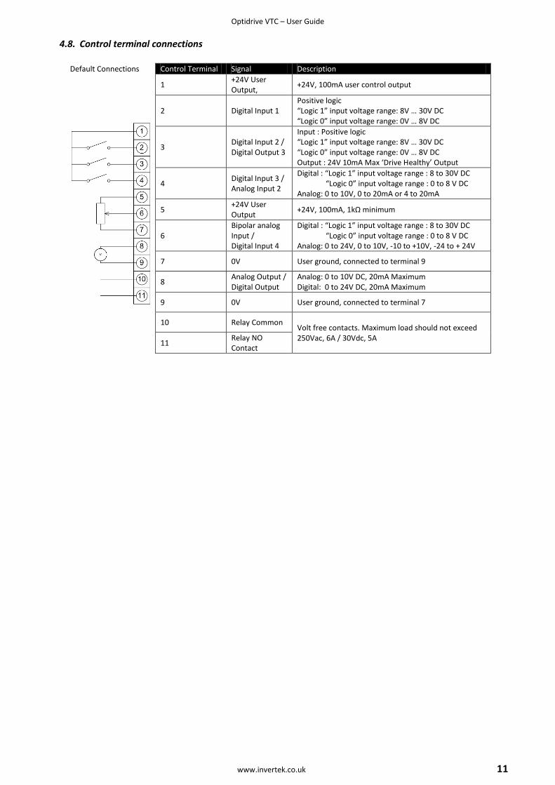
4.8. Control terminal connections
Default Connections Control Terminal Signal Description
1 +24V User Output,
+24V, 100mA user control output
2 Digital Input 1 Positive logic “Logic 1” input voltage range: 8V … 30V DC “Logic 0” input voltage range: 0V … 8V DC
3 Digital Input 2 / Digital Output 3
Input : Positive logic “Logic 1” input voltage range: 8V … 30V DC “Logic 0” input voltage range: 0V … 8V DC Output : 24V 10mA Max ‘Drive Healthy’ Output
4 Digital Input 3 / Analog Input 2
Digital : “Logic 1” input voltage range : 8 to 30V DC “Logic 0” input voltage range : 0 to 8 V DC Analog: 0 to 10V, 0 to 20mA or 4 to 20mA
5 +24V User Output
+24V, 100mA, 1kΩ minimum
6 Bipolar analog Input / Digital Input 4
Digital : “Logic 1” input voltage range : 8 to 30V DC “Logic 0” input voltage range : 0 to 8 V DC Analog: 0 to 24V, 0 to 10V, -10 to +10V, -24 to + 24V
7 0V User ground, connected to terminal 9
8 Analog Output / Digital Output
Analog: 0 to 10V DC, 20mA Maximum Digital: 0 to 24V DC, 20mA Maximum
9 0V User ground, connected to terminal 7
10 Relay Common Volt free contacts. Maximum load should not exceed 250Vac, 6A / 30Vdc, 5A
11 Relay NO Contact
Optidrive VTC – User Guide
12 www.invertek.co.uk
5. Operation
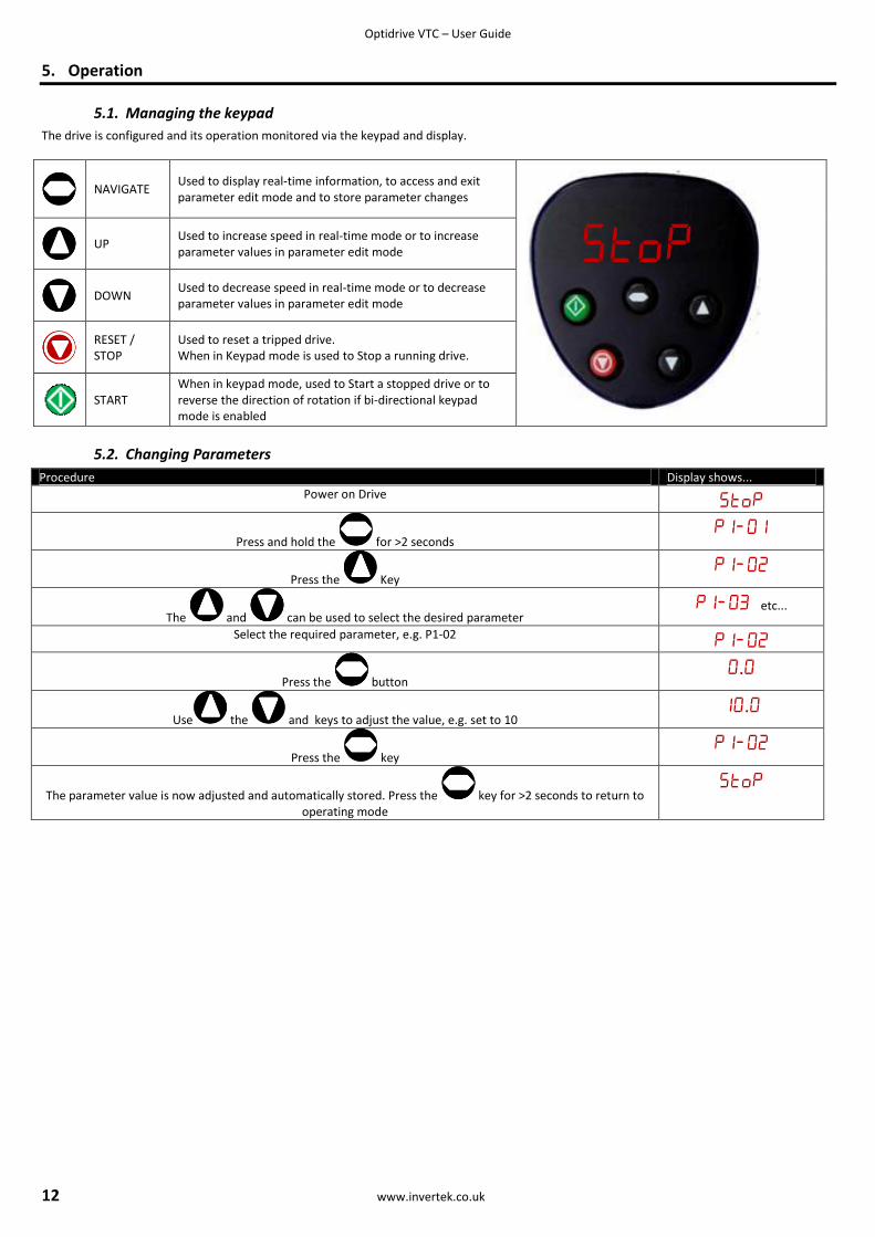
5.1. Managing the keypad
The drive is configured and its operation monitored via the keypad and display.
NAVIGATE
Used to display real-time information, to access and exit parameter edit mode and to store parameter changes
UP
Used to increase speed in real-time mode or to increase parameter values in parameter edit mode
DOWN
Used to decrease speed in real-time mode or to decrease parameter values in parameter edit mode
RESET / STOP
Used to reset a tripped drive. When in Keypad mode is used to Stop a running drive.
START
When in keypad mode, used to Start a stopped drive or to reverse the direction of rotation if bi-directional keypad mode is enabled
5.2. Changing Parameters
Procedure Display shows...
Power on Drive
Press and hold the for >2 seconds
Press the Key
The and can be used to select the desired parameter etc...
Select the required parameter, e.g. P1-02
Press the button .
Use the and keys to adjust the value, e.g. set to 10 .
Press the key
The parameter value is now adjusted and automatically stored. Press the key for >2 seconds to return to operating mode
Optidrive VTC – User Guide
www.invertek.co.uk 13
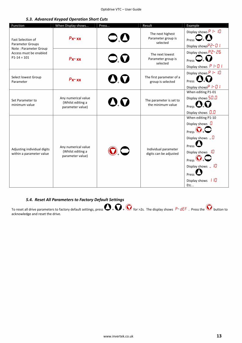
5.3. Advanced Keypad Operation Short Cuts
Function When Display shows... Press... Result Example
Fast Selection of Parameter Groups Note : Parameter Group Access must be enabled P1-14 = 101
xxx +
The next highest Parameter group is
selected
Display shows
Press +
Display shows
xxx+
The next lowest Parameter group is
selected
Display shows
Press +
Display shows
Select lowest Group Parameter xxx
+
The first parameter of a group is selected
Display shows
Press +
Display shows
Set Parameter to minimum value
Any numerical value (Whilst editing a parameter value) +
The parameter is set to the minimum value
When editing P1-01
Display shows .
Press +
Display shows.
Adjusting individual digits within a parameter value
Any numerical value (Whilst editing a parameter value) +
Individual parameter digits can be adjusted
When editing P1-10
Display shows
Press +
Display shows
Press
Display shows
Press +
Display shows
Press
Display shows Etc...
5.4. Reset All Parameters to Factory Default Settings
To reset all drive parameters to factory default settings, press + + for >2s. The display shows . Press the button to acknowledge and reset the drive.
Optidrive VTC – User Guide
14 www.invertek.co.uk
5.5. Terminal Control
When delivered, the Optidrive is in the factory default state, meaning that it is set to operate in terminal control mode and all parameters have the default values as indicated in section 6 Parameters.
Connect the drive to the supply, ensuring the correct voltage and fusing / circuit breaker protection – see section 9.2 on page 26.
Connect the motor to the drive, ensuring the correct star/delta connection for the voltage rating - see section 4.6 on page 10.
Enter the motor data from motor nameplate; P1-07 = motor rated voltage, P1-08 = motor rated current, P1-09 = motor rated frequency.
Connect a control switch between the control terminals 1 and 2 ensuring that the contact is open (drive disabled).
Connect a potentiometer (1kΩ min to 10 kΩ max) between terminals 5 and 7, and the wiper to terminal 6.
With the potentiometer set to zero, switch on the supply to the drive. The display will show .
Close the control switch, terminals 1-2. The drive is now ‘enabled’ and the output frequency/speed are controlled by the potentiometer.
On first enable from factory default parameters, the Optidrive will carry out an Autotune, and the display shows . Leave the control switch closed an allow this to complete.
Following completion of the Autotune, the display shows zero speed in Hz (.) with the potentiometer turned to minimum.
Turn the potentiometer to maximum. The motor will accelerate to 50Hz, (60Hz for USA drives), the default value of P1-01, under the
control of the acceleration ramp time P1-03. The display shows 50Hz (.) at max speed.
If the potentiometer is turned to minimum, the motor will decelerate to 0Hz, the default minimum speed set in P1-02, under the control of the deceleration ramp P1-04. The output speed can be adjusted anywhere between minimum and maximum speed using the potentiometer.
To display motor current (Amps), briefly press the (Navigate) key.
Press again to display the motor power.
Press again to return to speed display.
To stop the motor, disable the drive by opening the control switch (terminals 1-2).
If the enable/disable switch is opened the drive will decelerate to stop at which time the display will show .
5.6. Keypad Control
To allow the Optidrive to be controlled from the keypad in a forward direction only, set P1-12 =1:
Connect the supply and motor as for terminal control above.
Enable the drive by closing the switch between control terminals 1 & 2. The display will show .
Press the key. If this is the first enable from factory default parameters, the drive will carry out an Autotune as described above. On
completion of the Autotune, the display shows ..
Press to increase speed.
The drive will run forward, increasing speed until is released.
Press to decrease speed. The drive will decrease speed until is released. The rate of deceleration is limited by the setting in P1-04
Press the key. The drive will decelerate to rest at the rate set in P1-04.
The display will finally show at which point the drive is disabled
To preset a target speed prior to enable, press the key whilst the drive is stopped. The display will show the target speed, use the
& keys to adjust as required then press the key to return the display to .
Pressing the key will start the drive accelerating to the target speed.
To allow the Optidrive to be controlled from the keypad in a forward and reverse direction, set P1-12 =2:
Operation is the same as when P1-12=1 for start, stop and changing speed.
Press the key. The display changes to ..
Press to increase speed
The drive will run forward, increasing speed until is released. Acceleration is limited by the setting in P1-03. The maximum speed is the speed set in P1-01.
To reverse the direction of rotation of the motor, press the key again.
Optidrive VTC – User Guide
www.invertek.co.uk 15
5.7. Motor Autotuning
Optidrive VTC uses a sophisticated Voltage Vector control method as a factory default setting to ensure best possible motor operation. This control method requires the Optidrive to carry out an autotune to measure certain motor parameters prior to operation, to ensure this function operates correctly, and reduce the risk of nuisance tripping.
Whilst the autotune procedure does not rotate the motor shaft, during the autotune procedure, the motor shaft may still turn. It is not normally necessary to uncouple the load from the motor, however the user should ensure any that no risk arises from the possible movement of the motor shaft.
Autotune after Factory Reset
Following a factory reset (See section 6.1.3), the correct data from the motor nameplate should be entered in P1-07, P1-08 and P1-09. Providing that P1-08 is adjusted from the factory default setting, the Optidrive will automatically carry out an autotune on the motor the first time it is
enabled. During the autotune, the display will show . The test procedure may take several minutes to complete depending on the motor. Once the autotune is completed, the drive will operate as normal, and no further autotuning will be required unless the motor or drive control mode is changed (P4-01).
User Selected Autotune
The user can program the drive to carry an autotune if required, as follows:- Ensure the motor nameplate values are correctly entered in P1-07 (Motor Rated Voltage), P1-08 (Motor Rated Current) and P1-09 (Motor Rated Frequency) Set P1-14 = 101 to allow access to Parameter Groups 2, 3 and 4 Set P4-02 = 1
The autotune will begin immediately when P4-02 is set to 1, and no external enable signal is required. During the autotune procedure, the motor shaft may turn. It is not normally necessary to uncouple the load from the motor, however the user should ensure any that no risk arises from the possible movement of the motor shaft.
5.8. Operation of Three Phase drives on Single Phase Supplies
Applies to: - Optidrive VTC, 230 Volt Supply versions, Size 3 and above Optidrive VTC, 400 Volt Supply versions, Size 2 and above It is possible to operate the above drive units from a single phase supply of the same rated voltage. When used in this way, the maximum output current capacity is reduced by 50%. In order to operate on a single phase supply, the supply MUST be connected to the L1 and L2 terminals of the
drive. The user must then press + + for >2s. The display will show , and all parameters will be reset to factory default
settings. Press the button to acknowledge and reset the drive. The maximum motor rated current setting in P1-08 will now be limited to 50% of its original value, and the Phase Loss and Phase Imbalance Protection features will be disabled.
Optidrive VTC – User Guide
16 www.invertek.co.uk
6. Parameters
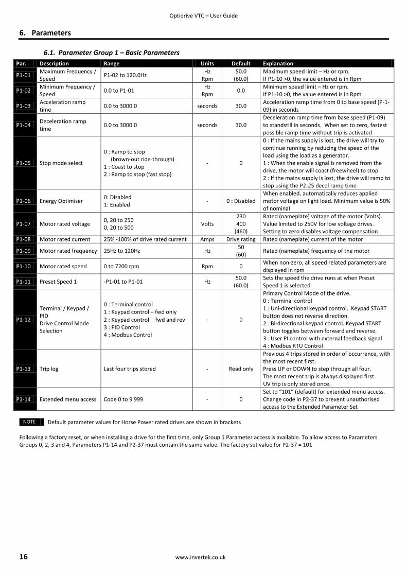
6.1. Parameter Group 1 – Basic Parameters
NOTE Default parameter values for Horse Power rated drives are shown in brackets
Following a factory reset, or when installing a drive for the first time, only Group 1 Parameter access is available. To allow access to Parameters Groups 0, 2, 3 and 4, Parameters P1-14 and P2-37 must contain the same value. The factory set value for P2-37 = 101
Par. Description Range Units Default Explanation
P1-01 Maximum Frequency / Speed
P1-02 to 120.0Hz Hz
Rpm 50.0
(60.0) Maximum speed limit – Hz or rpm. If P1-10 >0, the value entered is in Rpm
P1-02 Minimum Frequency / Speed
0.0 to P1-01 Hz
Rpm 0.0
Minimum speed limit – Hz or rpm. If P1-10 >0, the value entered is in Rpm
P1-03 Acceleration ramp time
0.0 to 3000.0 seconds 30.0 Acceleration ramp time from 0 to base speed (P-1-09) in seconds
P1-04 Deceleration ramp time
0.0 to 3000.0 seconds 30.0 Deceleration ramp time from base speed (P1-09) to standstill in seconds. When set to zero, fastest possible ramp time without trip is activated
P1-05 Stop mode select
0 : Ramp to stop (brown-out ride-through) 1 : Coast to stop 2 : Ramp to stop (fast stop)
- 0
0 : If the mains supply is lost, the drive will try to continue running by reducing the speed of the load using the load as a generator. 1 : When the enable signal is removed from the drive, the motor will coast (freewheel) to stop 2 : If the mains supply is lost, the drive will ramp to stop using the P2-25 decel ramp time
P1-06 Energy Optimiser 0: Disabled 1: Enabled
- 0 : Disabled When enabled, automatically reduces applied motor voltage on light load. Minimum value is 50% of nominal
P1-07 Motor rated voltage 0, 20 to 250 0, 20 to 500
Volts 230 400
(460)
Rated (nameplate) voltage of the motor (Volts). Value limited to 250V for low voltage drives. Setting to zero disables voltage compensation
P1-08 Motor rated current 25% -100% of drive rated current Amps Drive rating Rated (nameplate) current of the motor
P1-09 Motor rated frequency 25Hz to 120Hz Hz 50
(60) Rated (nameplate) frequency of the motor
P1-10 Motor rated speed 0 to 7200 rpm Rpm 0 When non-zero, all speed related parameters are displayed in rpm
P1-11 Preset Speed 1 -P1-01 to P1-01 Hz 50.0
(60.0) Sets the speed the drive runs at when Preset Speed 1 is selected
P1-12
Terminal / Keypad / PID Drive Control Mode Selection
0 : Terminal control 1 : Keypad control – fwd only
2 : Keypad control fwd and rev 3 : PID Control 4 : Modbus Control
- 0
Primary Control Mode of the drive. 0 : Terminal control 1 : Uni-directional keypad control. Keypad START button does not reverse direction. 2 : Bi-directional keypad control. Keypad START button toggles between forward and reverse. 3 : User PI control with external feedback signal 4 : Modbus RTU Control
P1-13 Trip log Last four trips stored - Read only
Previous 4 trips stored in order of occurrence, with the most recent first. Press UP or DOWN to step through all four. The most recent trip is always displayed first. UV trip is only stored once.
P1-14 Extended menu access Code 0 to 9 999 - 0 Set to “101” (default) for extended menu access. Change code in P2-37 to prevent unauthorised access to the Extended Parameter Set

Optidrive VTC – User Guide
www.invertek.co.uk 17
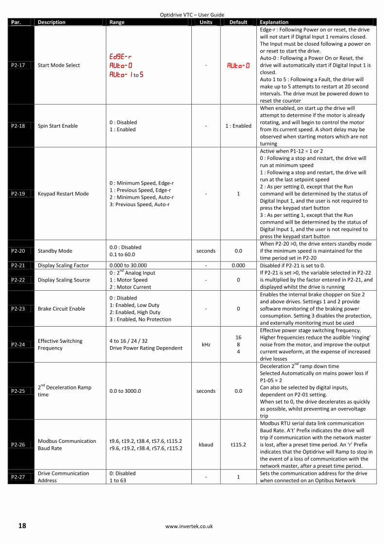
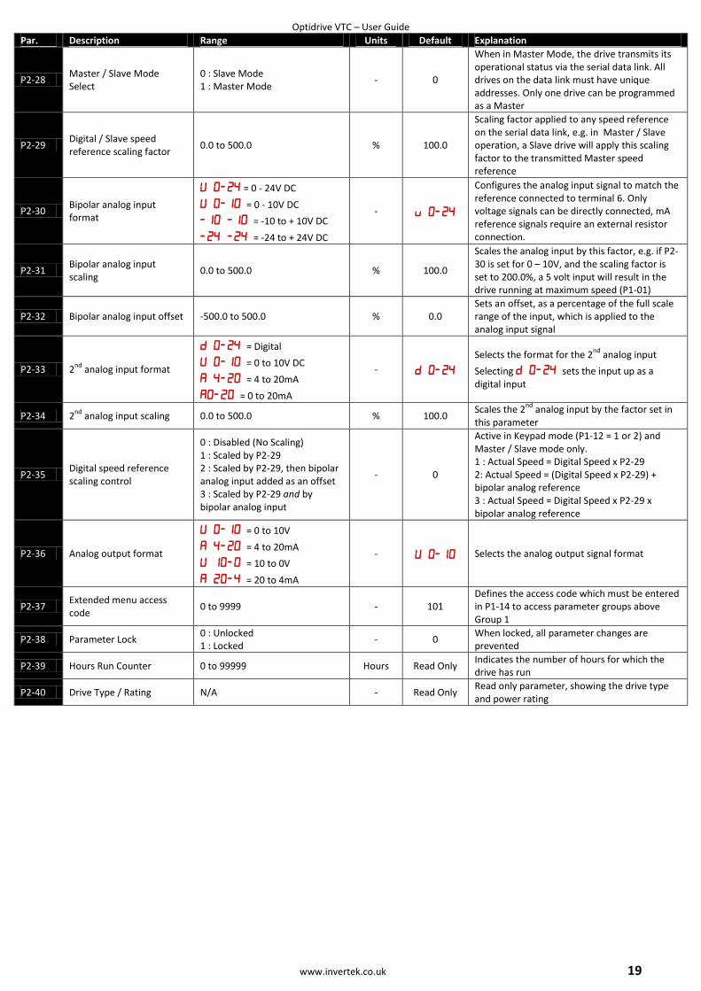
6.2. Parameter Group 2 - Extended parameters
Par. Description Range Units Default Explanation
P2-01 Digital input function select
0 to 23 - 0
Defines the function of the digital inputs depending on the control mode setting in P-12. See section 7 Analog and Digital Input Configurations for more information.
P2-02 Preset Speed 2 -P1-01 to P1-01 Hz 0.0 Sets jog / preset speed 2
P2-03 Preset Speed 3 -P1-01 to P1-01 Hz 0.0 Sets jog / preset speed 3
P2-04 Preset Speed 4 -P1-01 to P1-01 Hz 0.0 Sets jog / preset speed 4
P2-05 Preset Speed 5 -P1-01 to P1-01 Hz 0.0 Sets jog /preset speed 5
P2-06 Preset Speed 6 -P1-01 to P1-01 Hz 0.0 Sets jog / preset speed 6
P2-07 Preset speed 7 -P1-01 to P1-01 Hz 0.0 Sets jog / preset speed 7
P2-08 Preset speed 8 -P1-01 to P1-01 Hz 0.0 Sets jog / preset speed 8
P2-09 Skip frequency P1-02 to P1-01 Hz 0.0 Centre point of skip frequency band set up in conjunction with P2-10
P2-10 Skip frequency band 0 to P1-01 Hz 0.0 Width of skip frequency band centred on frequency set in P2-09
P2-11 Analog output / Digital Output 1 Function select
Digital output mode 0 : Drive enabled 1 : Drive healthy 2 : Motor at target speed 3 : Motor Speed > 0 4 : Motor speed >= limit 5 : Motor current >= limit 6 : 2
nd Analog Input >= limit
Analog Output Mode 7 : Motor speed 8 : Motor Current 9 : Motor power
7
Digital Output Mode. Logic 1 = +24V DC 0 : Logic 1 when the drive is enabled (Running) 1: Logic 1 When no Fault condition exists on the drive 2 : Logic 1 when the motor speed matches the setpoint speed 3 : Logic 1 when the motor runs above zero speed Options 4 to 6 : the Digital output is enabled using the level set in P2-12h and P2-12L Analog Output Mode 7 : Motor Speed, 0 to 10V = 0 to P-01 8 : Motor Current, 0 to 10V = 0 to 200% of P1-08 9 : Motor power, 0 to 10V = 0 to 150% of drive rated power 10 :
P2-12h Digital Output Control High Limit
0.0 to 200.0 % 100.0 With P2-11 = 4 to 6, Digital Output 1 is set to Logic 1 (+24V DC) when the value set in P2-12h is exceeded, and returns to Logic 0 (0V) when the selected value reduces below the limit set in P2-12L
P2-12L Digital Output Control Low Limit
0.0 to P2-12h % 100.0
P2-13 User Relay Output Function Select
0 : Drive enabled 1 : Drive healthy 2 : Motor at target speed 3 : Motor Speed >0 4 : Motor speed >= limit 5 : Motor current >= limit 6 : 2
nd Analog Input >= limit
1
Selects the function assigned to the relay output. 0 : Logic 1 when the drive is enabled (Running) 1 : Logic 1 When no Fault condition exists on the drive 2 : Logic 1 when the motor speed matches the setpoint speed 3 : Logic 1 when the motor runs above zero speed Options 4 to 6 : the Digital output is enabled using the level set in P2-14h and P2-14L
P2-14h Relay Output Control High Limit
0.0 to 200.0 % 100.0 With P2-13 = 4 to 6, the User Relay Output is set to Logic 1 (+24V DC) when the value set in P2-14h is exceeded, and returns to Logic 0 (0V) when the selected value reduces below the limit set in P2-12L
P2-14L Relay Output Control Low Limit
0.0 to P2-14h % 100.0
P2-15 Relay Output Mode 0 : Normally Open 1 : Normally Closed
- 0
Inverts the operating status of the User Relay 0 : Logic 1 = Relay Contacts Closed 1 : Logic 1 = Relay Contacts Open The drive must be powered for the contacts to close
P2-16 Standby Mode Wake Up Speed
0.0 to 100.0 % 0.0 Drive will wake from Standby Mode if the setpoint exceeds this value
Optidrive VTC – User Guide
18 www.invertek.co.uk
Par. Description Range Units Default Explanation
P2-17 Start Mode Select
to
-
Edge-r : Following Power on or reset, the drive will not start if Digital Input 1 remains closed. The Input must be closed following a power on or reset to start the drive. Auto-0 : Following a Power On or Reset, the drive will automatically start if Digital Input 1 is closed. Auto 1 to 5 : Following a Fault, the drive will make up to 5 attempts to restart at 20 second intervals. The drive must be powered down to reset the counter
P2-18 Spin Start Enable 0 : Disabled 1 : Enabled
- 1 : Enabled
When enabled, on start up the drive will attempt to determine if the motor is already rotating, and will begin to control the motor from its current speed. A short delay may be observed when starting motors which are not turning
P2-19 Keypad Restart Mode
0 : Minimum Speed, Edge-r 1 : Previous Speed, Edge-r 2 : Minimum Speed, Auto-r 3: Previous Speed, Auto-r
- 1
Active when P1-12 = 1 or 2 0 : Following a stop and restart, the drive will run at minimum speed 1 : Following a stop and restart, the drive will run at the last setpoint speed 2 : As per setting 0, except that the Run command will be determined by the status of Digital Input 1, and the user is not required to press the keypad start button 3 : As per setting 1, except that the Run command will be determined by the status of Digital Input 1, and the user is not required to press the keypad start button
P2-20 Standby Mode 0.0 : Disabled 0.1 to 60.0
seconds 0.0 When P2-20 >0, the drive enters standby mode if the minimum speed is maintained for the time period set in P2-20
P2-21 Display Scaling Factor 0.000 to 30.000 - 0.000 Disabled if P2-21 is set to 0. If P2-21 is set >0, the variable selected in P2-22 is multiplied by the factor entered in P2-21, and displayed whilst the drive is running
P2-22 Display Scaling Source 0 : 2
nd Analog Input
1 : Motor Speed 2 : Motor Current
- 0
P2-23 Brake Circuit Enable
0 : Disabled 1: Enabled, Low Duty 2: Enabled, High Duty 3 : Enabled, No Protection
- 0
Enables the internal brake chopper on Size 2 and above drives. Settings 1 and 2 provide software monitoring of the braking power consumption. Setting 3 disables the protection, and externally monitoring must be used
P2-24 Effective Switching Frequency
4 to 16 / 24 / 32 Drive Power Rating Dependent
kHz 16 8 4
Effective power stage switching frequency. Higher frequencies reduce the audible ‘ringing’ noise from the motor, and improve the output current waveform, at the expense of increased drive losses
P2-25 2
nd Deceleration Ramp
time 0.0 to 3000.0 seconds 0.0
Deceleration 2nd
ramp down time Selected Automatically on mains power loss if P1-05 = 2 Can also be selected by digital inputs, dependent on P2-01 setting. When set to 0, the drive decelerates as quickly as possible, whilst preventing an overvoltage trip
P2-26 Modbus Communication Baud Rate
t9.6, t19.2, t38.4, t57.6, t115.2 r9.6, r19.2, r38.4, r57.6, r115.2
kbaud t115.2
Modbus RTU serial data link communication Baud Rate. A‘t’ Prefix indicates the drive will trip if communication with the network master is lost, after a preset time period. An ‘r’ Prefix indicates that the Optidrive will Ramp to stop in the event of a loss of communication with the network master, after a preset time period.
P2-27 Drive Communication Address
0: Disabled 1 to 63
- 1 Sets the communication address for the drive when connected on an Optibus Network
Optidrive VTC – User Guide
www.invertek.co.uk 19
Par. Description Range Units Default Explanation
P2-28 Master / Slave Mode Select
0 : Slave Mode 1 : Master Mode
- 0
When in Master Mode, the drive transmits its operational status via the serial data link. All drives on the data link must have unique addresses. Only one drive can be programmed as a Master
P2-29 Digital / Slave speed reference scaling factor
0.0 to 500.0 % 100.0
Scaling factor applied to any speed reference on the serial data link, e.g. in Master / Slave operation, a Slave drive will apply this scaling factor to the transmitted Master speed reference
P2-30 Bipolar analog input format
= 0 - 24V DC
= 0 - 10V DC
= -10 to + 10V DC
= -24 to + 24V DC
-
Configures the analog input signal to match the reference connected to terminal 6. Only voltage signals can be directly connected, mA reference signals require an external resistor connection.
P2-31 Bipolar analog input scaling
0.0 to 500.0 % 100.0
Scales the analog input by this factor, e.g. if P2-30 is set for 0 – 10V, and the scaling factor is set to 200.0%, a 5 volt input will result in the drive running at maximum speed (P1-01)
P2-32 Bipolar analog input offset -500.0 to 500.0 % 0.0 Sets an offset, as a percentage of the full scale range of the input, which is applied to the analog input signal
P2-33 2nd
analog input format
= Digital
= 0 to 10V DC
= 4 to 20mA
= 0 to 20mA
-
Selects the format for the 2nd
analog input
Selecting sets the input up as a digital input
P2-34 2nd
analog input scaling 0.0 to 500.0 % 100.0 Scales the 2
nd analog input by the factor set in
this parameter
P2-35 Digital speed reference scaling control
0 : Disabled (No Scaling) 1 : Scaled by P2-29 2 : Scaled by P2-29, then bipolar analog input added as an offset 3 : Scaled by P2-29 and by bipolar analog input
- 0
Active in Keypad mode (P1-12 = 1 or 2) and Master / Slave mode only. 1 : Actual Speed = Digital Speed x P2-29 2: Actual Speed = (Digital Speed x P2-29) + bipolar analog reference 3 : Actual Speed = Digital Speed x P2-29 x bipolar analog reference
P2-36 Analog output format
= 0 to 10V
= 4 to 20mA
= 10 to 0V
= 20 to 4mA
- Selects the analog output signal format
P2-37 Extended menu access code
0 to 9999 - 101 Defines the access code which must be entered in P1-14 to access parameter groups above Group 1
P2-38 Parameter Lock 0 : Unlocked 1 : Locked
- 0 When locked, all parameter changes are prevented
P2-39 Hours Run Counter 0 to 99999 Hours Read Only Indicates the number of hours for which the drive has run
P2-40 Drive Type / Rating N/A - Read Only Read only parameter, showing the drive type and power rating
Optidrive VTC – User Guide
20 www.invertek.co.uk
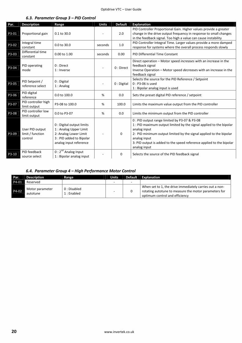
6.3. Parameter Group 3 – PID Control
6.4. Parameter Group 4 – High Performance Motor Control
Par. Description Range Units Default Explanation
P3-01 Proportional gain 0.1 to 30.0 - 2.0 PID Controller Proportional Gain. Higher values provide a greater change in the drive output frequency in response to small changes in the feedback signal. Too high a value can cause instability
P3-02 Integral time constant
0.0 to 30.0 seconds 1.0 PID Controller Integral Time. Larger values provide a more damped response for systems where the overall process responds slowly
P3-03 Differential time constant
0.00 to 1.00 seconds 0.00 PID Differential Time Constant
P3-04 PID operating mode
0 : Direct 1 : Inverse
- 0 : Direct
Direct operation – Motor speed increases with an increase in the feedback signal Inverse Operation – Motor speed decreases with an increase in the feedback signal
P3-05 PID Setpoint / reference select
0 : Digital 1 : Analog
- 0 : Digital Selects the source for the PID Reference / Setpoint 0 : P3-06 is used 1 : Bipolar analog input is used
P3-06 PID digital reference
0.0 to 100.0 % 0.0 Sets the preset digital PID reference / setpoint
P3-07 PID controller high limit output
P3-08 to 100.0 % 100.0 Limits the maximum value output from the PID controller
P3-08 PID controller low limit output
0.0 to P3-07 % 0.0 Limits the minimum output from the PID controller
P3-09 User PID output limit / function control
0 : Digital output limits 1 : Analog Upper Limit 2: Analog Lower Limit 3 : PID added to Bipolar analog input reference
- 0
0 : PID output range limited by P3-07 & P3-08 1 : PID maximum output limited by the signal applied to the bipolar analog input 2: PID minimum output limited by the signal applied to the bipolar analog input 3: PID output is added to the speed reference applied to the bipolar analog input
P3-10 PID feedback source select
0 : 2nd
Analog Input 1 : Bipolar analog input
- 0 Selects the source of the PID feedback signal
Par. Description Range Units Default Explanation
P4-01 Reserved - -
P4-02 Motor parameter autotune
0 : Disabled 1 : Enabled
- 0 When set to 1, the drive immediately carries out a non-rotating autotune to measure the motor parameters for optimum control and efficiency
Optidrive VTC – User Guide
www.invertek.co.uk 21
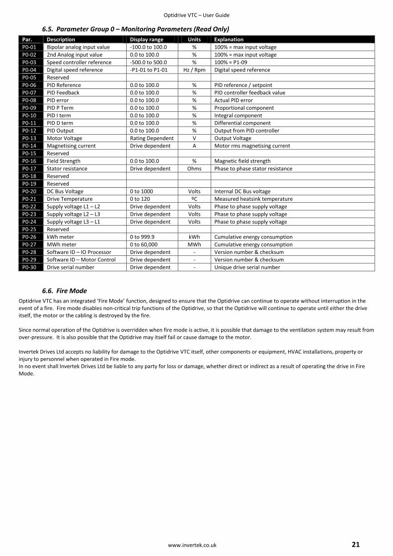
6.5. Parameter Group 0 – Monitoring Parameters (Read Only)
Par. Description Display range Units Explanation
P0-01 Bipolar analog input value -100.0 to 100.0 % 100% = max input voltage
P0-02 2nd Analog input value 0.0 to 100.0 % 100% = max input voltage
P0-03 Speed controller reference -500.0 to 500.0 % 100% = P1-09
P0-04 Digital speed reference -P1-01 to P1-01 Hz / Rpm Digital speed reference
P0-05 Reserved
P0-06 PID Reference 0.0 to 100.0 % PID reference / setpoint
P0-07 PID Feedback 0.0 to 100.0 % PID controller feedback value
P0-08 PID error 0.0 to 100.0 % Actual PID error
P0-09 PID P Term 0.0 to 100.0 % Proportional component
P0-10 PID I term 0.0 to 100.0 % Integral component
P0-11 PID D term 0.0 to 100.0 % Differential component
P0-12 PID Output 0.0 to 100.0 % Output from PID controller
P0-13 Motor Voltage Rating Dependent V Output Voltage
P0-14 Magnetising current Drive dependent A Motor rms magnetising current
P0-15 Reserved
P0-16 Field Strength 0.0 to 100.0 % Magnetic field strength
P0-17 Stator resistance Drive dependent Ohms Phase to phase stator resistance
P0-18 Reserved
P0-19 Reserved
P0-20 DC Bus Voltage 0 to 1000 Volts Internal DC Bus voltage
P0-21 Drive Temperature 0 to 120 ºC Measured heatsink temperature
P0-22 Supply voltage L1 – L2 Drive dependent Volts Phase to phase supply voltage
P0-23 Supply voltage L2 – L3 Drive dependent Volts Phase to phase supply voltage
P0-24 Supply voltage L3 – L1 Drive dependent Volts Phase to phase supply voltage
P0-25 Reserved
P0-26 kWh meter 0 to 999.9 kWh Cumulative energy consumption
P0-27 MWh meter 0 to 60,000 MWh Cumulative energy consumption
P0-28 Software ID – IO Processor Drive dependent - Version number & checksum
P0-29 Software ID – Motor Control Drive dependent - Version number & checksum
P0-30 Drive serial number Drive dependent - Unique drive serial number
6.6. Fire Mode
Optidrive VTC has an integrated ‘Fire Mode’ function, designed to ensure that the Optidrive can continue to operate without interruption in the event of a fire. Fire mode disables non-critical trip functions of the Optidrive, so that the Optidrive will continue to operate until either the drive itself, the motor or the cabling is destroyed by the fire. Since normal operation of the Optidrive is overridden when fire mode is active, it is possible that damage to the ventilation system may result from over-pressure. It is also possible that the Optidrive may itself fail or cause damage to the motor. Invertek Drives Ltd accepts no liability for damage to the Optidrive VTC itself, other components or equipment, HVAC installations, property or injury to personnel when operated in Fire mode. In no event shall Invertek Drives Ltd be liable to any party for loss or damage, whether direct or indirect as a result of operating the drive in Fire Mode.

Optidrive VTC – User Guide
22 www.invertek.co.uk
7. Analog and Digital Input Configurations
7.1. Terminal mode (P1-12 =0)
P2-01 Digital input 1 (T2) Digital input 2 (T3) Digital input 3 (T4) Analog input (T6)
0 Open: Stop (disable) Closed: Run (enable)
Open : Bipolar analog speed ref Closed : Preset speed ref
Open : Preset Speed 1 Closed : Preset Speed 2
Bipolar analog input
1 Open: Stop (disable) Closed: Run (enable)
Open: Preset Speed 1 Closed: Preset speed 2
Open: Preset speed 1 / 2 Closed: Preset speed 3
Open : Preset Speed 1 / 2 / 3 Closed : Preset Speed 4
2 Open: Stop (disable) Closed: Run (enable)
Digital Input 2 Digital Input 3 Bipolar analog input Speed Setpoint
Open Open Open Preset Speed 1
Closed Open Open Preset Speed 2
Open Closed Open Preset Speed 3
Closed Closed Open Preset Speed 4
Open Open Closed Preset Speed 5
Closed Open Closed Preset Speed 6
Open Closed Closed Preset Speed 7
Closed Closed Closed Preset Speed 8
3 Open: Stop (disable) Closed: Run (enable)
Open : Forward Closed : Reverse
Open: Bipolar analog ref Closed: Preset Speed 1
Bipolar analog input
4 Open: Stop (disable) Closed: Run (enable)
Open : Forward Closed : Reverse
Analog input 2 Speed Reference No Function
5 Open: Stop (disable) Closed: Run (enable)
Open : Forward Closed : Reverse
Digital Input 3 Bipolar analog input Speed Setpoint
Open Open Preset Speed 1
Closed Open Preset Speed 2
Open Closed Preset Speed 3
Closed Closed Preset Speed 4
6 Open: Stop (disable) Closed: Run (enable)
Open : Forward Closed : Reverse
External trip input : Open: Trip, Closed: No Trip
Bipolar analog input
7 Open: Stop (disable) Closed: Fwd Run (enable)
Open: Stop (disable) Closed: Rev Run (enable)
Open: Bipolar analog speed ref Closed: Preset Speed 1
Bipolar analog input
8 Open: Stop (disable) Closed: Fwd Run (enable)
Open: Stop (disable) Closed: Rev Run (enable)
Open: Preset Speed 1 Closed: Bipolar Analog Ref
Bipolar analog input
9 Open: Stop (disable) Closed: Forward Run (enable)
Open: Stop (disable) Closed: Reverse Run (enable)
Digital Input 3 Bipolar analog input Preset Speed
Open Open Preset Speed 1
Closed Open Preset Speed 2
Open Closed Preset Speed 3
Closed Closed Preset Speed 4
10 Open: Stop (disable) Closed: Forward Run (enable)
Open: Stop (disable) Closed: Reverse Run (enable)
External trip input : Open: Trip, Closed: No Trip
Bipolar analog input
11 Open: Stop (disable) Closed: Run (enable)
Open : Bipolar analog speed ref Closed : Preset speed 1
External trip input : Open: Trip, Closed: No Trip
Bipolar analog input
12 Open: Stop (disable) Closed: Run (enable)
Open : Preset Speed 1 Closed : Bipolar analog speed ref
External trip input : Open: Trip, Closed: No Trip
Bipolar analog input
13 Normally Open (NO) Momentarily Close to Run
Normally Closed (NC) Momentarily Open to Stop
Open: Bipolar analog speed ref Closed: Preset Speed 1
Bipolar analog input
14 Normally Open (NO) Momentarily Close to Run Fwd
Normally Closed (NC) Momentarily Open to Stop
Normally Open (NO) Momentarily Close to Run Rev
Bipolar analog input
15 Open: Stop (disable) Closed: Run (enable)
Open : Forward Closed : Reverse
Open: Decel Ramp 1 (P1-04) Closed: Decel Ramp 2 (P2-25)
Bipolar analog input
16 Open: Stop (disable) Closed: Run (enable)
Open : Forward Closed : Reverse
Open: Decel Ramp 1 (P1-04) Closed: Decel Ramp 2 (P2-25)
Open: Preset Speed 1 Closed : Preset speed 2
17 Normally Open (NO) Momentarily Close to Run Fwd
Normally Closed (NC) Momentarily Open to Stop
Normally Open (NO) Momentarily Close to Run Rev
Open: Preset Speed 1 Closed : Keypad Speed Ref
18 Open: Stop (disable) Closed: Run (enable)
Digital Input 2 Digital Input 3 Preset Speed Ref
Open : Preset Speed Ref Closed : Keypad Speed Ref
Open Open Preset Speed 1
Closed Open Preset Speed 2
Open Closed Preset Speed 3
Closed Closed Preset Speed 4
19 Open: Stop (disable) Closed: Run (enable)
Open : Bipolar analog speed ref Closed : Analog input 2 speed ref
Analog input 2 Bipolar analog input
20 Open: Stop (disable) Closed: Run (enable)
Digital Output : Drive Healthy = +24V
Open : Bipolar analog speed ref Closed : Preset Speed 1
Bipolar analog input
21 Open: Stop (disable) Closed: Run (enable)
Digital Output : Drive Healthy = +24V
Open : Forward Closed : Reverse
Bipolar analog input
22 Open: Stop (disable) Closed: Run (enable)
Digital Output : Drive Healthy = +24V
External trip input : Open: Trip, Closed: No Trip
Bipolar analog input
23 Open: Stop (disable) Closed: Run (enable)
Open : Normal Operation Closed : Fire Mode
Open: Bipolar analog ref Closed: Preset Speed 1
Bipolar analog input
NOTE Negative Preset Speeds will be inverted if Run Reverse selected. The external trip input can be used to connect a motor thermistor by connecting between terminals 1 and 4
Optidrive VTC – User Guide
www.invertek.co.uk 23
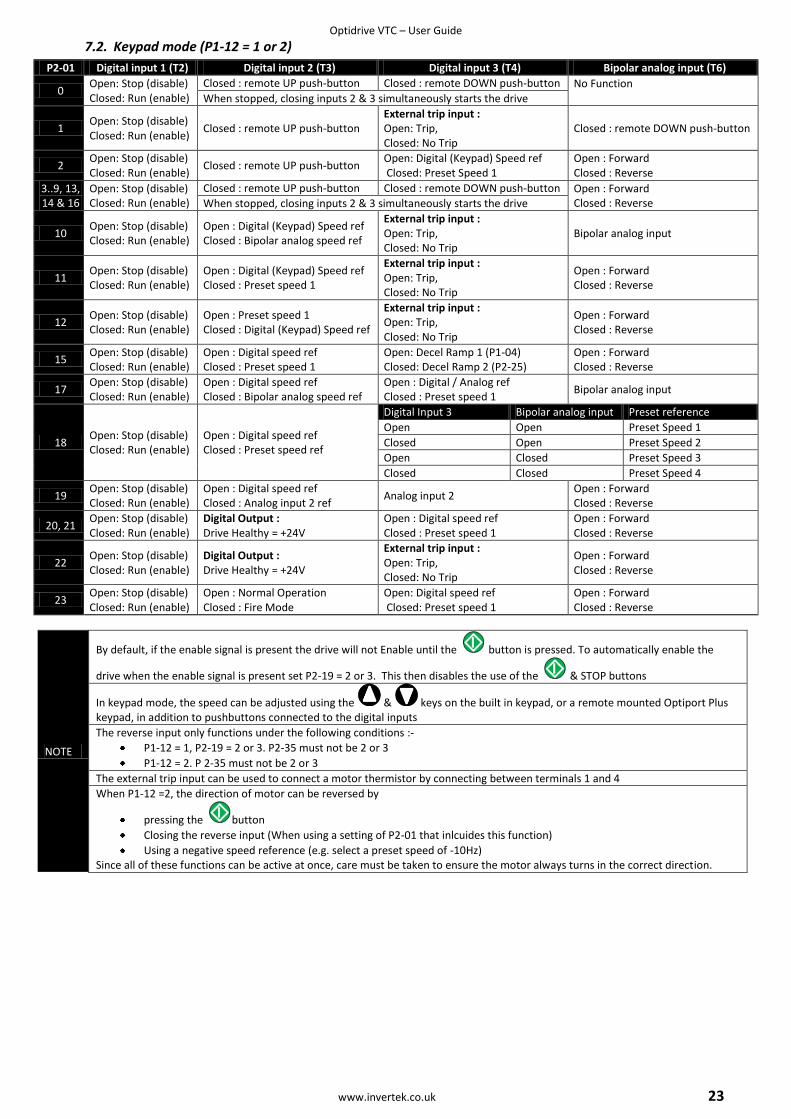
7.2. Keypad mode (P1-12 = 1 or 2)
P2-01 Digital input 1 (T2) Digital input 2 (T3) Digital input 3 (T4) Bipolar analog input (T6)
0 Open: Stop (disable) Closed: Run (enable)
Closed : remote UP push-button Closed : remote DOWN push-button No Function When stopped, closing inputs 2 & 3 simultaneously starts the drive
1 Open: Stop (disable) Closed: Run (enable)
Closed : remote UP push-button External trip input : Open: Trip, Closed: No Trip
Closed : remote DOWN push-button
2 Open: Stop (disable) Closed: Run (enable)
Closed : remote UP push-button Open: Digital (Keypad) Speed ref Closed: Preset Speed 1
Open : Forward Closed : Reverse
3..9, 13, 14 & 16
Open: Stop (disable) Closed: Run (enable)
Closed : remote UP push-button Closed : remote DOWN push-button Open : Forward Closed : Reverse When stopped, closing inputs 2 & 3 simultaneously starts the drive
10 Open: Stop (disable) Closed: Run (enable)
Open : Digital (Keypad) Speed ref Closed : Bipolar analog speed ref
External trip input : Open: Trip, Closed: No Trip
Bipolar analog input
11 Open: Stop (disable) Closed: Run (enable)
Open : Digital (Keypad) Speed ref Closed : Preset speed 1
External trip input : Open: Trip, Closed: No Trip
Open : Forward Closed : Reverse
12 Open: Stop (disable) Closed: Run (enable)
Open : Preset speed 1 Closed : Digital (Keypad) Speed ref
External trip input : Open: Trip, Closed: No Trip
Open : Forward Closed : Reverse
15 Open: Stop (disable) Closed: Run (enable)
Open : Digital speed ref Closed : Preset speed 1
Open: Decel Ramp 1 (P1-04) Closed: Decel Ramp 2 (P2-25)
Open : Forward Closed : Reverse
17 Open: Stop (disable) Closed: Run (enable)
Open : Digital speed ref Closed : Bipolar analog speed ref
Open : Digital / Analog ref Closed : Preset speed 1
Bipolar analog input
18 Open: Stop (disable) Closed: Run (enable)
Open : Digital speed ref Closed : Preset speed ref
Digital Input 3 Bipolar analog input Preset reference
Open Open Preset Speed 1
Closed Open Preset Speed 2
Open Closed Preset Speed 3
Closed Closed Preset Speed 4
19 Open: Stop (disable) Closed: Run (enable)
Open : Digital speed ref Closed : Analog input 2 ref
Analog input 2 Open : Forward Closed : Reverse
20, 21 Open: Stop (disable) Closed: Run (enable)
Digital Output : Drive Healthy = +24V
Open : Digital speed ref Closed : Preset speed 1
Open : Forward Closed : Reverse
22 Open: Stop (disable) Closed: Run (enable)
Digital Output : Drive Healthy = +24V
External trip input : Open: Trip, Closed: No Trip
Open : Forward Closed : Reverse
23 Open: Stop (disable) Closed: Run (enable)
Open : Normal Operation Closed : Fire Mode
Open: Digital speed ref Closed: Preset speed 1
Open : Forward Closed : Reverse
NOTE
By default, if the enable signal is present the drive will not Enable until the button is pressed. To automatically enable the
drive when the enable signal is present set P2-19 = 2 or 3. This then disables the use of the & STOP buttons
In keypad mode, the speed can be adjusted using the & keys on the built in keypad, or a remote mounted Optiport Plus keypad, in addition to pushbuttons connected to the digital inputs
The reverse input only functions under the following conditions :-
P1-12 = 1, P2-19 = 2 or 3. P2-35 must not be 2 or 3
P1-12 = 2. P 2-35 must not be 2 or 3
The external trip input can be used to connect a motor thermistor by connecting between terminals 1 and 4
When P1-12 =2, the direction of motor can be reversed by
pressing the button
Closing the reverse input (When using a setting of P2-01 that inlcuides this function)
Using a negative speed reference (e.g. select a preset speed of -10Hz) Since all of these functions can be active at once, care must be taken to ensure the motor always turns in the correct direction.
Optidrive VTC – User Guide
24 www.invertek.co.uk
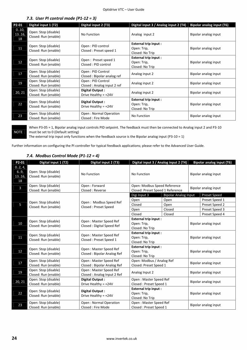
7.3. User PI control mode (P1-12 = 3)
P2-01 Digital input 1 (T2) Digital input 2 (T3) Digital input 3 / Analog input 2 (T4) Bipolar analog input (T6)
0..10, 13..16,
18
Open: Stop (disable) Closed: Run (enable)
No Function Analog input 2 Bipolar analog input
11 Open: Stop (disable) Closed: Run (enable)
Open : PID control Closed : Preset speed 1
External trip input : Open: Trip, Closed: No Trip
Bipolar analog input
12 Open: Stop (disable) Closed: Run (enable)
Open : Preset speed 1 Closed : PID control
External trip input : Open: Trip, Closed: No Trip
Bipolar analog input
17 Open: Stop (disable) Closed: Run (enable)
Open : PID Control Closed : Bipolar analog ref
Analog input 2 Bipolar analog input
19 Open: Stop (disable) Closed: Run (enable)
Open : PID Control Closed : Analog input 2 ref
Analog input 2 Bipolar analog input
20, 21 Open: Stop (disable) Closed: Run (enable)
Digital Output : Drive Healthy = +24V
Analog input 2 Bipolar analog input
22 Open: Stop (disable) Closed: Run (enable)
Digital Output : Drive Healthy = +24V
External trip input : Open: Trip, Closed: No Trip
Bipolar analog input
23 Open: Stop (disable) Closed: Run (enable)
Open : Normal Operation Closed : Fire Mode
No Function Bipolar analog input
NOTE When P3-05 = 1, Bipolar analog input controls PID setpoint. The feedback must then be connected to Analog input 2 and P3-10 must be set to 0 (Default setting) The external trip input only functions when the feedback source is the Bipolar analog input (P3-10 = 1)
Further information on configuring the PI controller for typical feedback applications; please refer to the Advanced User Guide.
7.4. Modbus Control Mode (P1-12 = 4)
P2-01 Digital input 1 (T2) Digital input 2 (T3) Digital input 3 / Analog input 2 (T4) Bipolar analog input (T6)
0..2, 4, 6..9,
13..16, 18
Open: Stop (disable) Closed: Run (enable)
No Function No Function Bipolar analog input
3 Open: Stop (disable) Closed: Run (enable)
Open : Forward Closed : Reverse
Open: Modbus Speed Reference Closed: Preset Speed 1 Reference
Bipolar analog input
5 Open: Stop (disable) Closed: Run (enable)
Open : Modbus Speed Ref Closed : Preset Speed
Digi Input 3 Bipolar Analog Input Preset Speed
Open Open Preset Speed 1
Closed Open Preset Speed 2
Open Closed Preset Speed 3
Closed Closed Preset Speed 4
10 Open: Stop (disable) Closed: Run (enable)
Open : Master Speed Ref Closed : Digital Speed Ref
External trip input : Open: Trip, Closed: No Trip
Bipolar analog input
11 Open: Stop (disable) Closed: Run (enable)
Open : Master Speed Ref Closed : Preset Speed 1
External trip input : Open: Trip, Closed: No Trip
Bipolar analog input
12 Open: Stop (disable) Closed: Run (enable)
Open : Master Speed Ref Closed : Bipolar Analog Ref
External trip input : Open: Trip, Closed: No Trip
Bipolar analog input
17 Open: Stop (disable) Closed: Run (enable)
Open : Master Speed Ref Closed : Bipolar Analog Ref
Open: Modbus / Analog Ref Closed: Preset Speed 1
Bipolar analog input
19 Open: Stop (disable) Closed: Run (enable)
Open : Master Speed Ref Closed : Analog Input 2 Ref
Analog Input 2 Bipolar analog input
20, 21 Open: Stop (disable) Closed: Run (enable)
Digital Output : Drive Healthy = +24V
Open : Master Speed Ref Closed : Preset Speed 1
Bipolar analog input
22 Open: Stop (disable) Closed: Run (enable)
Digital Output : Drive Healthy = +24V
External trip input : Open: Trip, Closed: No Trip
Bipolar analog input
23 Open: Stop (disable) Closed: Run (enable)
Open : Normal Operation Closed : Fire Mode
Open : Master Speed Ref Closed : Preset Speed 1
Bipolar analog input
Optidrive VTC – User Guide
www.invertek.co.uk 25
8. Troubleshooting
8.1. Fault messages
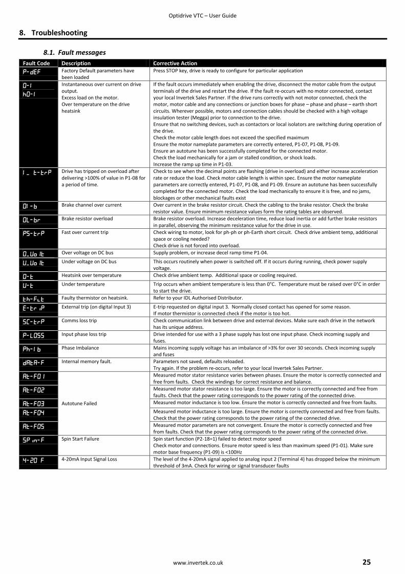
Fault Code Description Corrective Action
Factory Default parameters have been loaded
Press STOP key, drive is ready to configure for particular application
Instantaneous over current on drive output. Excess load on the motor. Over temperature on the drive heatsink
If the fault occurs immediately when enabling the drive, disconnect the motor cable from the output terminals of the drive and restart the drive. If the fault re-occurs with no motor connected, contact your local Invertek Sales Partner. If the drive runs correctly with not motor connected, check the motor, motor cable and any connections or junction boxes for phase – phase and phase – earth short circuits. Wherever possible, motors and connection cables should be checked with a high voltage insulation tester (Megga) prior to connection to the drive. Ensure that no switching devices, such as contactors or local isolators are switching during operation of the drive. Check the motor cable length does not exceed the specified maximum Ensure the motor nameplate parameters are correctly entered, P1-07, P1-08, P1-09. Ensure an autotune has been successfully completed for the connected motor. Check the load mechanically for a jam or stalled condition, or shock loads. Increase the ramp up time in P1-03.
Drive has tripped on overload after delivering >100% of value in P1-08 for a period of time.
Check to see when the decimal points are flashing (drive in overload) and either increase acceleration rate or reduce the load. Check motor cable length is within spec. Ensure the motor nameplate parameters are correctly entered, P1-07, P1-08, and P1-09. Ensure an autotune has been successfully completed for the connected motor. Check the load mechanically to ensure it is free, and no jams, blockages or other mechanical faults exist
Brake channel over current Over current in the brake resistor circuit. Check the cabling to the brake resistor. Check the brake resistor value. Ensure minimum resistance values form the rating tables are observed.
Brake resistor overload Brake resistor overload. Increase deceleration time, reduce load inertia or add further brake resistors in parallel, observing the minimum resistance value for the drive in use.
Fast over current trip Check wiring to motor, look for ph-ph or ph-Earth short circuit. Check drive ambient temp, additional space or cooling needed? Check drive is not forced into overload.
Over voltage on DC bus Supply problem, or increase decel ramp time P1-04.
Under voltage on DC bus This occurs routinely when power is switched off. If it occurs during running, check power supply voltage.
Heatsink over temperature Check drive ambient temp. Additional space or cooling required.
Under temperature Trip occurs when ambient temperature is less than 0°C. Temperature must be raised over 0°C in order to start the drive.
Faulty thermistor on heatsink. Refer to your IDL Authorised Distributor.
External trip (on digital Input 3) E-trip requested on digital input 3. Normally closed contact has opened for some reason. If motor thermistor is connected check if the motor is too hot.
Comms loss trip Check communication link between drive and external devices. Make sure each drive in the network has its unique address.
Input phase loss trip Drive intended for use with a 3 phase supply has lost one input phase. Check incoming supply and fuses.
Phase Imbalance Mains incoming supply voltage has an imbalance of >3% for over 30 seconds. Check incoming supply and fuses
Internal memory fault. Parameters not saved, defaults reloaded. Try again. If the problem re-occurs, refer to your local Invertek Sales Partner.
Autotune Failed
Measured motor stator resistance varies between phases. Ensure the motor is correctly connected and free from faults. Check the windings for correct resistance and balance.
Measured motor stator resistance is too large. Ensure the motor is correctly connected and free from faults. Check that the power rating corresponds to the power rating of the connected drive.
Measured motor inductance is too low. Ensure the motor is correctly connected and free from faults.
Measured motor inductance is too large. Ensure the motor is correctly connected and free from faults. Check that the power rating corresponds to the power rating of the connected drive.
Measured motor parameters are not convergent. Ensure the motor is correctly connected and free from faults. Check that the power rating corresponds to the power rating of the connected drive.
Spin Start Failure Spin start function (P2-18=1) failed to detect motor speed Check motor and connections. Ensure motor speed is less than maximum speed (P1-01). Make sure motor base frequency (P1-09) is <100Hz
4-20mA Input Signal Loss The level of the 4-20mA signal applied to analog input 2 (Terminal 4) has dropped below the minimum threshold of 3mA. Check for wiring or signal transducer faults

Optidrive VTC – User Guide
26 www.invertek.co.uk
9. Technical data
9.1. Environmental
Operational ambient temperature range: -10 … 50°C, Frost and condensation free Storage ambient temperature range: -40 … 60°C Maximum altitude: 2000m. Derate above 1000m : 1% / 100m Maximum humidity: 95%, non-condensing
9.2. Rating tables
200-240V ±10% - 1 Phase Input 3 Phase Output
Model (kW)
kW Model (HP)
HP Frame Size
Nominal Input
Current
Fuse or MCB
(type B)
Supply Cable Size
Nominal Output Current
110% Output Current 60 secs
Motor Cable Size
Max Motor Cable
Length
Min Brake
Res Value
Amps Amps mm2 Amps Amps mm
2 m Ω
ODV-22150 1.5 ODV-22020-USA 2 2 19.3 20 4 7 7.7 1.5 100 33
ODV-22220 2.2 ODV-22030-USA 3 2 28.8 32 6 10.5 (9) 11.6 (9.9) 1.5 100 22
NOTE For cUL compliance, fuse type Bussmann KTN-R / KTS-R or equivalent must be used
200-240V ±10% - 3 Phase Input drive model set for 1 Phase Operation (See section 5.8) 3 Phase Output
Model kW Model HP Frame Size
Nominal Input
Current
Fuse or MCB
(type B)
Supply Cable Size
Nominal Output Current
110% Output Current 60
secs
Motor Cable Size
Max Motor Cable
Length
Min Brake
Res Value
Amps Amps mm2 Amps Amps mm
2 m Ω
ODV-32030 1.5 ODV-32040-USA 2 3 19.3 20 4 7 7.7 1.5 100 15
ODV-32040 2.2 ODV-32050-USA 3 3 28.8 35 6 9 9.9 1.5 100 15
ODV-32055 3 ODV-32075-USA 4 3 31.3 35 6 12.5 (12) 13.8 (13.2) 2.5 100 15
ODV-42075 4 ODV-42100-USA 5 4 58.3 50 10 19.5 21.5 2.5 100 6
ODV-42110 5.5 ODV-42150-USA 7.5 4 67.6 80 16 23 25.3 4 100 6
ODV-42150 7.5 ODV-42200-USA 10 4 87.0 100 25 30.5 33.6 10 100 6
ODV-42185 9 ODV-42250-USA 12 4 96.1 100 25 36 39.6 10 100 6
ODV-42220 11 ODV-42300-USA 15 4 115.4 125 35 45 49.5 16 100 6
ODV-52300 15 ODV-52400-USA 20 5 146.1 160 50 55 60.5 16 100 3
ODV-52370 18.5 ODV-52500-USA 25 5 187.8 200 70 75 82.5 25 100 3
ODV-52450 22 ODV-52600-USA 30 5 220.6 250 90 90 99 25 100 3
NOTE Values shown in brackets are the maximum for UL applications For cUL compliance, fuse type Bussmann KTN-R / KTS-R or equivalent must be used
200-240V ±10% - 3 Phase Input 3 Phase Output
Model kW Model HP Frame Size
Nominal Input
Current
Fuse or MCB
(type B)
Supply Cable Size
Nominal Output Current
110% Output Current 60
secs
Motor Cable Size
Max Motor Cable
Length
Min Brake
Res Value
Amps Amps mm2 Amps Amps mm
2 m Ω
ODV3-22150 1.5 ODV3-22020-USA 2 2 9.2 10 2.5 7 7.7 1.5 100 33
ODV3-22220 2.2 ODV-22030-USA 3 2 13.7 16 4 10.5 (9) 11.6 (9.9) 1.5 100 22
ODV-32030 3 ODV-32040-USA 4 3 16.1 20 4 14 15.4 1.5 100 15
ODV-32040 4 ODV-32050-USA 5 3 17.3 20 6 18 19.8 1.5 100 15
ODV-32055 5.5 ODV-32075-USA 7.5 3 25 25 6 25 (24) 27.5 (26.4) 2.5 100 15
ODV-42075 7.5 ODV-42100-USA 10 4 46.6 50 10 39 42.9 2.5 100 6
ODV-42110 11 ODV-42150-USA 15 4 54.1 63 16 46 50.6 4 100 6
ODV-42150 15 ODV-42200-USA 20 4 69.6 80 25 61 67.1 10 100 6
ODV-42185 18.5 ODV-42250-USA 25 4 76.9 80 25 72 79.2 10 100 6
ODV-42220 22 ODV-42300-USA 30 4 92.3 100 35 90 99 16 100 6
ODV-52300 30 ODV-52400-USA 40 5 116.9 125 50 110 121 16 100 3
ODV-52370 37 ODV-52500-USA 50 5 150.2 160 70 150 165 25 100 3
ODV-52450 45 ODV-52600-USA 60 5 176.5 200 90 180 198 25 100 3
NOTE Values shown in brackets are the maximum for UL applications For cUL compliance, fuse type Bussmann KTN-R / KTS-R or equivalent must be used
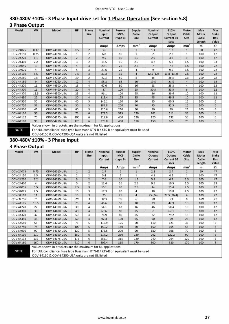
Optidrive VTC – User Guide
www.invertek.co.uk 27
380-480V ±10% - 3 Phase Input drive set for 1 Phase Operation (See section 5.8) 3 Phase Output
Model kW Model HP Frame Size
Nominal Input
Current
Fuse or MCB
(type B)
Supply Cable Size
Nominal Output Current
110% Output
Current 60 secs
Motor Cable Size
Max Motor Cable
Length
Min Brake
Res Value
Amps Amps mm2 Amps Amps mm
2 m Ω
ODV-24075 0.37 ODV-24010-USA 0.5 2 3.6 6 1 1.1 1.2 1 50 47
ODV-24150 0.75 ODV-24020-USA 1 2 6.8 10 1 2 2.2 1 100 47
ODV-24220 1.1 ODV-24030-USA 2 2 9.5 10 1.5 2.9 3.2 1 100 47
ODV-24400 2.2 ODV-24050-USA 3 2 15.5 16 2.5 4.7 5.2 1.5 100 33
ODV-34055 3 ODV-34075-USA 4 3 20.1 25 2.5 7 7.7 1.5 100 22
ODV-34075 4 ODV-34100-USA 5 3 21.6 25 4 9 9.9 1.5 100 22
ODV-34110 5.5 ODV-34150-USA 7.5 3 31.3 35 4 12.5 (12) 13.8 (13.2) 2.5 100 22
ODV-34150 7.5 ODV-34200-USA 10 3 41.1 50 6 15 16.5 2.5 100 22
ODV-44185 9 ODV-44250-USA 12 4 58.3 63 10 19.5 21.5 4 100 12
ODV-44220 11 ODV-44300-USA 15 4 67.6 80 16 23 25.3 4 100 12
ODV-44300 15 ODV-44400-USA 20 4 87 100 25 30.5 33.5 6 100 12
ODV-44370 18.5 ODV-44500-USA 25 4 96.1 100 25 36 39.6 10 100 12
ODV-44450 22 ODV-44600-USA 30 4 115.4 125 35 45 49.5 10 100 12
ODV-54550 30 ODV-54750-USA 40 5 146.1 160 50 55 60.5 16 100 6
ODV-54750 37 ODV-54100-USA 50 5 187.8 200 70 75 82.5 16 100 6
ODV-54900 45 ODV-54120-USA 60 5 220.6 250 90 90 99 25 100 6
ODV-64110 55 ODV-64150-USA 75 6 271.5 315 120 101 111 35 100 6
ODV-64132 75 ODV-64175-USA 100 6 319.6 400 120 120 132 55 100 6
ODV-64160 90 ODV-64210-USA 120 6 378.0 400 170 150 165 70 100 6
Values shown in brackets are the maximum for UL applications
NOTE For cUL compliance, fuse type Bussmann KTN-R / KTS-R or equivalent must be used
ODV-34150 & ODV-34200-USA units are not UL listed
380-480V ±10% - 3 Phase Input 3 Phase Output
Model kW Model HP Frame Size
Nominal Input
Current
Fuse or MCB
(type B)
Supply Cable Size
Nominal Output Current
110% Output
Current 60 secs
Motor Cable Size
Max Motor Cable
Length
Min Brake
Res Value
Amps Amps mm2 Amps Amps mm
2 m Ω
ODV-24075 0.75 ODV-24010-USA 1 2 2.9 6 1 2.2 2.4 1 50 47
ODV-24150 1.5 ODV-24020-USA 2 2 5.4 6 1 4.1 4.5 1 100 47
ODV-24220 2.2 ODV-24030-USA 3 2 7.6 10 1.5 5.8 6.4 1.5 100 47
ODV-24400 4 ODV-24050-USA 5 2 12.4 16 2.5 9.5 10.5 1.5 100 33
ODV-34055 5.5 ODV-34075-USA 7.5 3 16.1 20 2.5 14 15.4 2.5 100 22
ODV-34075 7.5 ODV-34100-USA 10 3 17.3 20 4 18 19.8 2.5 100 22
ODV-34110 11 ODV-34150-USA 15 3 25 25 4 25 (24) 27.5 (26.4) 4 100 22
ODV-34150 15 ODV-34200-USA 20 3 32.9 35 6 30 33 6 100 22
ODV-44185 18.5 ODV-44250-USA 25 4 46.6 50 10 39 42.9 10 100 12
ODV-44220 22 ODV-44300-USA 30 4 54.1 63 16 46 50.4 10 100 12
ODV-44300 30 ODV-44400-USA 40 4 69.6 80 25 61 67.1 16 100 12
ODV-44370 37 ODV-44500-USA 50 4 76.9 80 25 72 79.2 16 100 12
ODV-44450 45 ODV-44600-USA 60 4 92.3 100 35 90 99 25 100 12
ODV-54550 55 ODV-54750-USA 75 5 116.9 125 50 110 121 35 100 6
ODV-54750 75 ODV-54100-USA 100 5 150.2 160 70 150 165 55 100 6
ODV-54900 90 ODV-54120-USA 120 5 176.5 200 90 180 198 70 100 6
ODV-64110 110 ODV-64150-USA 150 6 217.2 250 120 202 222.2 90 100 6
ODV-64132 132 ODV-64175-USA 175 6 255.7 315 120 240 264 120 100 6
ODV-64160 160 ODV-64210-USA 210 6 302.4 315 170 300 330 170 100 6
NOTE Values shown in brackets are the maximum for UL applications
For cUL compliance, fuse type Bussmann KTN-R / KTS-R or equivalent must be used ODV-34150 & ODV-34200-USA units are not UL listed
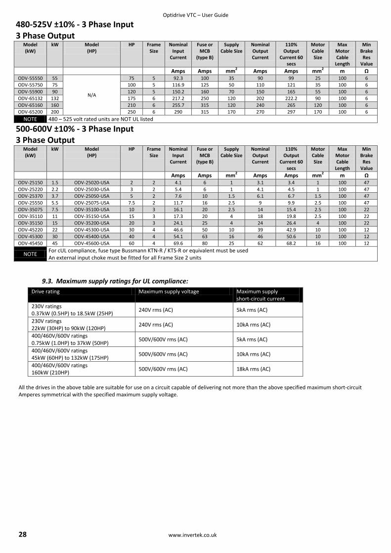
Optidrive VTC – User Guide
28 www.invertek.co.uk
480-525V ±10% - 3 Phase Input 3 Phase Output
Model (kW)
kW Model (HP)
HP Frame Size
Nominal Input
Current
Fuse or MCB
(type B)
Supply Cable Size
Nominal Output Current
110% Output
Current 60 secs
Motor Cable Size
Max Motor Cable
Length
Min Brake
Res Value
Amps Amps mm2 Amps Amps mm
2 m Ω
ODV-55550 55
N/A
75 5 92.3 100 35 90 99 25 100 6
ODV-55750 75 100 5 116.9 125 50 110 121 35 100 6
ODV-55900 90 120 5 150.2 160 70 150 165 55 100 6
ODV-65132 132 175 6 217.2 250 120 202 222.2 90 100 6
ODV-65160 160 210 6 255.7 315 120 240 265 120 100 6
ODV-65200 200 250 6 290 315 170 270 297 170 100 6
NOTE 480 – 525 volt rated units are NOT UL listed
500-600V ±10% - 3 Phase Input 3 Phase Output
Model (kW)
kW Model (HP)
HP Frame Size
Nominal Input
Current
Fuse or MCB
(type B)
Supply Cable Size
Nominal Output Current
110% Output
Current 60 secs
Motor Cable Size
Max Motor Cable
Length
Min Brake
Res Value
Amps Amps mm2 Amps Amps mm
2 m Ω
ODV-25150 1.5 ODV-25020-USA 2 2 4.1 6 1 3.1 3.4 1 100 47
ODV-25220 2.2 ODV-25030-USA 3 2 5.4 6 1 4.1 4.5 1 100 47
ODV-25370 3.7 ODV-25050-USA 5 2 7.6 10 1.5 6.1 6.7 1.5 100 47
ODV-25550 5.5 ODV-25075-USA 7.5 2 11.7 16 2.5 9 9.9 2.5 100 47
ODV-35075 7.5 ODV-35100-USA 10 3 16.1 20 2.5 14 15.4 2.5 100 22
ODV-35110 11 ODV-35150-USA 15 3 17.3 20 4 18 19.8 2.5 100 22
ODV-35150 15 ODV-35200-USA 20 3 24.1 25 4 24 26.4 4 100 22
ODV-45220 22 ODV-45300-USA 30 4 46.6 50 10 39 42.9 10 100 12
ODV-45300 30 ODV-45400-USA 40 4 54.1 63 16 46 50.6 10 100 12
ODV-45450 45 ODV-45600-USA 60 4 69.6 80 25 62 68.2 16 100 12
NOTE For cUL compliance, fuse type Bussmann KTN-R / KTS-R or equivalent must be used An external input choke must be fitted for all Frame Size 2 units
9.3. Maximum supply ratings for UL compliance:
Drive rating Maximum supply voltage Maximum supply short-circuit current
230V ratings 0.37kW (0.5HP) to 18.5kW (25HP)
240V rms (AC) 5kA rms (AC)
230V ratings 22kW (30HP) to 90kW (120HP)
240V rms (AC) 10kA rms (AC)
400/460V/600V ratings 0.75kW (1.0HP) to 37kW (50HP)
500V/600V rms (AC) 5kA rms (AC)
400/460V/600V ratings 45kW (60HP) to 132kW (175HP)
500V/600V rms (AC) 10kA rms (AC)
400/460V/600V ratings 160kW (210HP)
500V/600V rms (AC) 18kA rms (AC)
All the drives in the above table are suitable for use on a circuit capable of delivering not more than the above specified maximum short-circuit Amperes symmetrical with the specified maximum supply voltage.
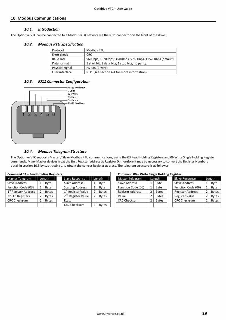
Optidrive VTC – User Guide
www.invertek.co.uk 29
10. Modbus Communications
10.1. Introduction
The Optidrive VTC can be connected to a Modbus RTU network via the RJ11 connector on the front of the drive.
10.2. Modbus RTU Specification
Protocol Modbus RTU
Error check CRC
Baud rate 9600bps, 19200bps, 38400bps, 57600bps, 115200bps (default)
Data format 1 start bit, 8 data bits, 1 stop bits, no parity.
Physical signal RS 485 (2-wire)
User interface RJ11 (see section 4.4 for more information)
10.3. RJ11 Connector Configuration
10.4. Modbus Telegram Structure
The Optidrive VTC supports Master / Slave Modbus RTU communications, using the 03 Read Holding Registers and 06 Write Single Holding Register commands. Many Master devices treat the first Register address as Register 0; therefore it may be necessary to convert the Register Numbers detail in section 10.5 by subtracting 1 to obtain the correct Register address. The telegram structure is as follows:-
Command 03 – Read Holding Registers Command 06 – Write Single Holding Register
Master Telegram Length Slave Response Length Master Telegram Length Slave Response Length
Slave Address 1 Byte Slave Address 1 Byte Slave Address 1 Byte Slave Address 1 Byte
Function Code (03) 1 Byte Starting Address 1 Byte Function Code (06) 1 Byte Function Code (06) 1 Byte
1st
Register Address 2 Bytes 1st
Register Value 2 Bytes Register Address 2 Bytes Register Address 2 Bytes
No. Of Registers 2 Bytes 2nd
Register Value 2 Bytes Value 2 Bytes Register Value 2 Bytes
CRC Checksum 2 Bytes Etc... CRC Checksum 2 Bytes CRC Checksum 2 Bytes
CRC Checksum 2 Bytes
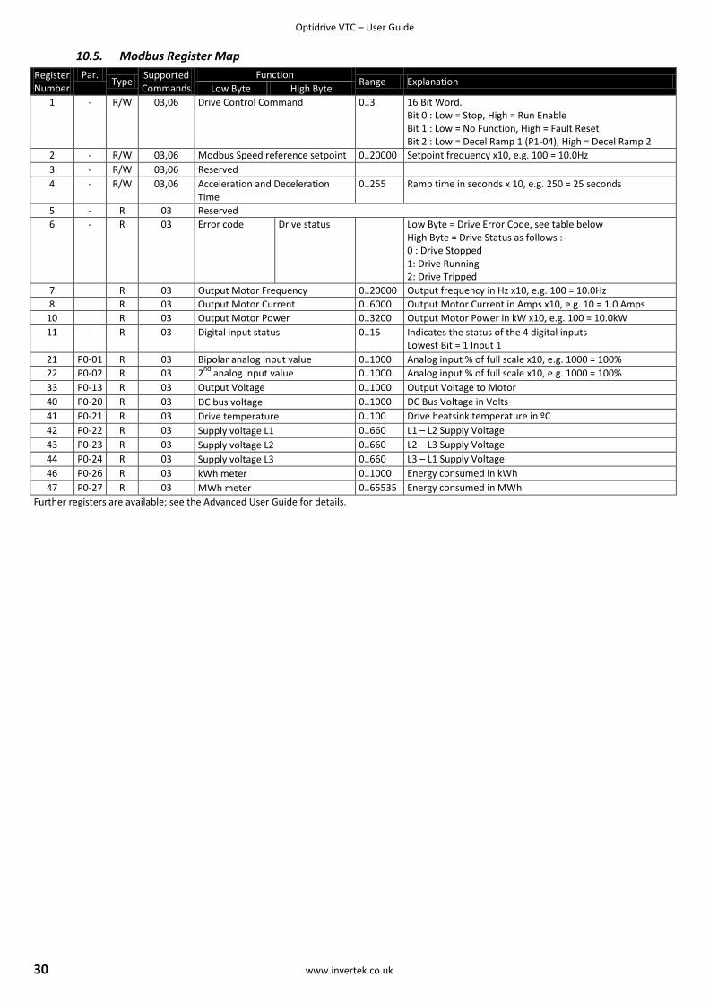
Optidrive VTC – User Guide
30 www.invertek.co.uk
10.5. Modbus Register Map
Register Number
Par. Type
Supported Commands
Function Range Explanation
Low Byte High Byte
1 - R/W 03,06 Drive Control Command 0..3 16 Bit Word. Bit 0 : Low = Stop, High = Run Enable Bit 1 : Low = No Function, High = Fault Reset Bit 2 : Low = Decel Ramp 1 (P1-04), High = Decel Ramp 2
2 - R/W 03,06 Modbus Speed reference setpoint 0..20000 Setpoint frequency x10, e.g. 100 = 10.0Hz
3 - R/W 03,06 Reserved
4 - R/W 03,06 Acceleration and Deceleration Time
0..255 Ramp time in seconds x 10, e.g. 250 = 25 seconds
5 - R 03 Reserved
6 - R 03 Error code Drive status Low Byte = Drive Error Code, see table below High Byte = Drive Status as follows :- 0 : Drive Stopped 1: Drive Running 2: Drive Tripped
7 R 03 Output Motor Frequency 0..20000 Output frequency in Hz x10, e.g. 100 = 10.0Hz
8 R 03 Output Motor Current 0..6000 Output Motor Current in Amps x10, e.g. 10 = 1.0 Amps
10 R 03 Output Motor Power 0..3200 Output Motor Power in kW x10, e.g. 100 = 10.0kW
11 - R 03 Digital input status 0..15 Indicates the status of the 4 digital inputs Lowest Bit = 1 Input 1
21 P0-01 R 03 Bipolar analog input value 0..1000 Analog input % of full scale x10, e.g. 1000 = 100%
22 P0-02 R 03 2nd
analog input value 0..1000 Analog input % of full scale x10, e.g. 1000 = 100%
33 P0-13 R 03 Output Voltage 0..1000 Output Voltage to Motor
40 P0-20 R 03 DC bus voltage 0..1000 DC Bus Voltage in Volts
41 P0-21 R 03 Drive temperature 0..100 Drive heatsink temperature in ºC
42 P0-22 R 03 Supply voltage L1 0..660 L1 – L2 Supply Voltage
43 P0-23 R 03 Supply voltage L2 0..660 L2 – L3 Supply Voltage
44 P0-24 R 03 Supply voltage L3 0..660 L3 – L1 Supply Voltage
46 P0-26 R 03 kWh meter 0..1000 Energy consumed in kWh
47 P0-27 R 03 MWh meter 0..65535 Energy consumed in MWh
Further registers are available; see the Advanced User Guide for details.
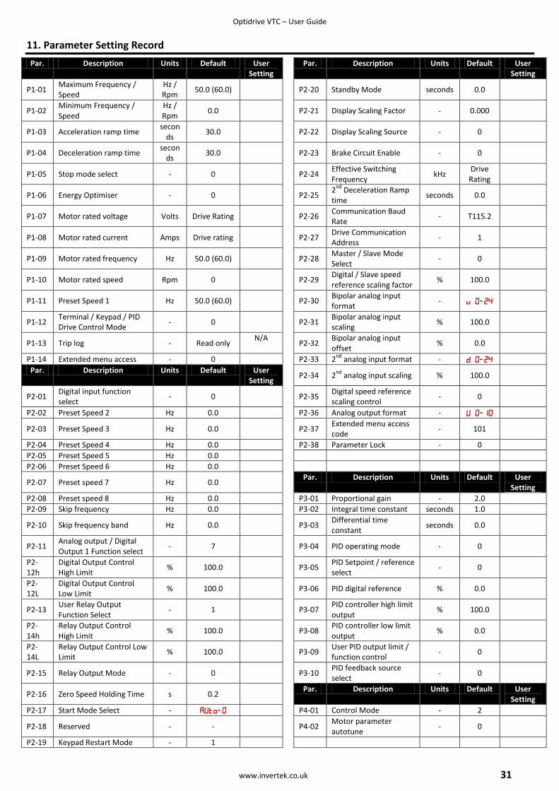
Optidrive VTC – User Guide
www.invertek.co.uk 31
11. Parameter Setting Record
Par. Description Units Default User Setting
Par. Description Units Default User Setting
P1-01 Maximum Frequency / Speed
Hz / Rpm
50.0 (60.0)
P2-20 Standby Mode seconds 0.0
P1-02 Minimum Frequency / Speed
Hz / Rpm
0.0
P2-21 Display Scaling Factor - 0.000
P1-03 Acceleration ramp time secon
ds 30.0
P2-22 Display Scaling Source - 0
P1-04 Deceleration ramp time secon
ds 30.0
P2-23 Brake Circuit Enable - 0
P1-05 Stop mode select - 0
P2-24 Effective Switching Frequency
kHz Drive
Rating
P1-06 Energy Optimiser - 0
P2-25 2
nd Deceleration Ramp
time seconds 0.0
P1-07 Motor rated voltage Volts Drive Rating
P2-26 Communication Baud Rate
- T115.2
P1-08 Motor rated current Amps Drive rating
P2-27 Drive Communication Address
- 1
P1-09 Motor rated frequency Hz 50.0 (60.0)
P2-28 Master / Slave Mode Select
- 0
P1-10 Motor rated speed Rpm 0
P2-29 Digital / Slave speed reference scaling factor
% 100.0
P1-11 Preset Speed 1 Hz 50.0 (60.0)
P2-30 Bipolar analog input format
-
P1-12 Terminal / Keypad / PID Drive Control Mode
- 0
P2-31 Bipolar analog input scaling
% 100.0
P1-13 Trip log - Read only N/A
P2-32 Bipolar analog input offset
% 0.0
P1-14 Extended menu access - 0 P2-33 2nd
analog input format -
Par. Description Units Default User Setting
P2-34 2
nd analog input scaling % 100.0
P2-01 Digital input function select
- 0
P2-35 Digital speed reference scaling control
- 0
P2-02 Preset Speed 2 Hz 0.0 P2-36 Analog output format -
P2-03 Preset Speed 3 Hz 0.0
P2-37 Extended menu access code
- 101
P2-04 Preset Speed 4 Hz 0.0 P2-38 Parameter Lock - 0
P2-05 Preset Speed 5 Hz 0.0
P2-06 Preset Speed 6 Hz 0.0
P2-07 Preset speed 7 Hz 0.0 Par. Description Units Default User
Setting
P2-08 Preset speed 8 Hz 0.0 P3-01 Proportional gain - 2.0
P2-09 Skip frequency Hz 0.0 P3-02 Integral time constant seconds 1.0
P2-10 Skip frequency band Hz 0.0
P3-03 Differential time constant
seconds 0.0
P2-11 Analog output / Digital Output 1 Function select
- 7
P3-04 PID operating mode - 0
P2-12h
Digital Output Control High Limit
% 100.0
P3-05 PID Setpoint / reference select
- 0
P2-12L
Digital Output Control Low Limit
% 100.0
P3-06 PID digital reference % 0.0
P2-13 User Relay Output Function Select
- 1
P3-07 PID controller high limit output
% 100.0
P2-14h
Relay Output Control High Limit
% 100.0
P3-08 PID controller low limit output
% 0.0
P2-14L
Relay Output Control Low Limit
% 100.0
P3-09 User PID output limit / function control
- 0
P2-15 Relay Output Mode - 0
P3-10 PID feedback source select
- 0
P2-16 Zero Speed Holding Time s 0.2 Par. Description Units Default User
Setting
P2-17 Start Mode Select - P4-01 Control Mode - 2
P2-18 Reserved - -
P4-02 Motor parameter autotune
- 0
P2-19 Keypad Restart Mode - 1
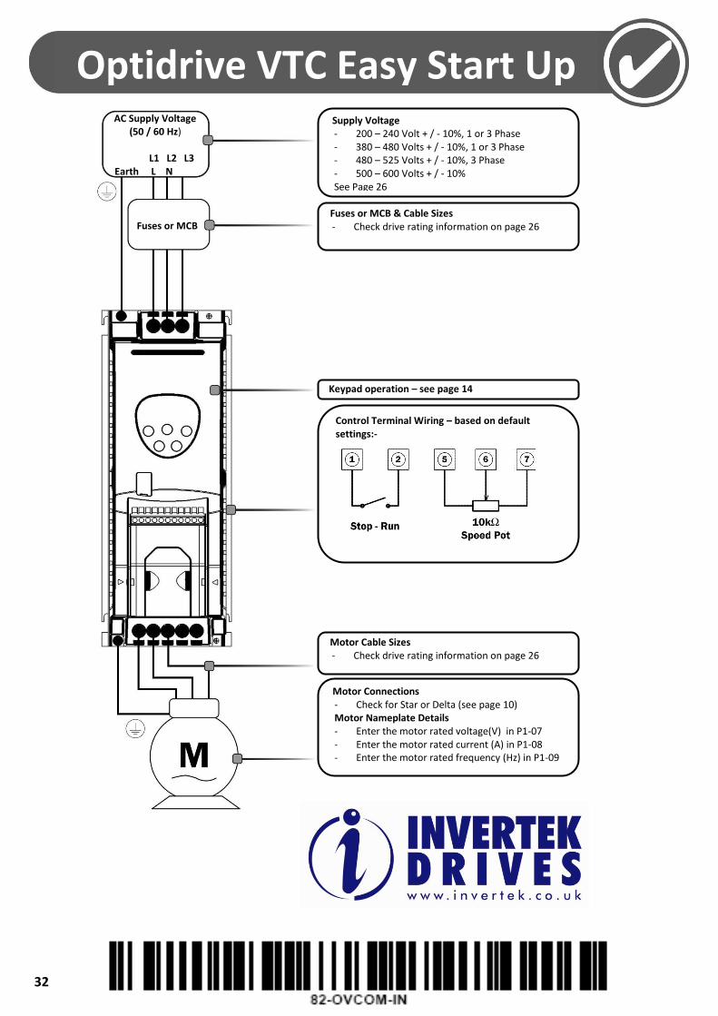
Optidrive VTC – User Guide
32 www.invertek.co.uk
Supply Voltage - 200 – 240 Volt + / - 10%, 1 or 3 Phase - 380 – 480 Volts + / - 10%, 1 or 3 Phase - 480 – 525 Volts + / - 10%, 3 Phase - 500 – 600 Volts + / - 10% See Page 26
Fuses or MCB & Cable Sizes - Check drive rating information on page 26
Keypad operation – see page 14
Motor Cable Sizes - Check drive rating information on page 26
Motor Connections - Check for Star or Delta (see page 10) Motor Nameplate Details - Enter the motor rated voltage(V) in P1-07 - Enter the motor rated current (A) in P1-08 - Enter the motor rated frequency (Hz) in P1-09
Optidrive VTC Easy Start Up Guide
Control Terminal Wiring – based on default settings:-
AC Supply Voltage (50 / 60 Hz)
L1 L2 L3 Earth L N
Fuses or MCB