user guide… · the express written permission of ... built to the highest standards using quality...
TRANSCRIPT

1
USER GUIDE
TM

2
© Harman International Industries Ltd. 2007All rights reservedParts of the design of this product may be protected by worldwide patents.Part No. ZM0357-02Rev B.Soundcraft is a trading division of Harman International Industries Ltd. Informationin this manual is subject to change without notice and does not represent acommitment on the part of the vendor. Soundcraft shall not be liable for anyloss or damage whatsoever arising from the use of information or any errorcontained in this manual.No part of this manual may be reproduced, stored in a retrieval system, ortransmitted, in any form or by any means, electronic, electrical, mechanical,optical, chemical, including photocopying and recording, for any purpose withoutthe express written permission of Soundcraft.
Harman International Industries LimitedCranborne HouseCranborne RoadPOTTERS BARHertfordshireEN6 3JNUK
Tel: +44 (0)1707 665000Fax: +44 (0)1707 660742http://www.soundcraft.com
IMPORTANTPlease read this manual carefully before using
your mixer for the first time.

3
ContentsSAFETY SYMBOL GUIDE 5IMPORTANT SAFETY INSTRUCTIONS 6INTRODUCTION 8BLOCK DIAGRAM 9WIRING UP 10CONSOLE CONTROLS 14Lexicon® FX PROCESSOR 22USING YOUR CONSOLE 31APPLICATIONS 33MARKUP SHEET 41TYPICAL CONNECTING LEADS 42REPOSITIONING THE REAR PANEL FOR RACKMOUNTING 44DIMENSIONS 45FX16ii TYPICAL SPECIFICATIONS 46WARRANTY 47

4

5
SAFETY SYMBOL GUIDEFor your own safety and to avoid invalidation of the warranty all text markedwith these symbols should be read carefully.
WARNINGSThe lightning flash with arrowhead symbol, is intended toalert the user to the presence of un-insulated “dangerous
voltage” within the product’s enclosure that may be ofsufficient magnitude to constitute a risk of electric shock to
persons.
CAUTIONSThe exclamation point within an equilateral triangle isintended to alert the user to the presence of important
operating and maintenance (servicing) instructions in theliterature accompanying the appliance.
NOTESContain important information and useful tips on the
operation of your equipment.
HEADPHONES SAFETY WARNINGContain important information and useful tips on headphone
outputs and monitoring levels.
Recommended Headphone Impedance >= 150 Ohms.

6
IMPORTANT SAFETY INSTRUCTIONS
Read these instructions.
Keep these instructions.
Heed all warnings.
Follow all instructions.
Do not use this apparatus near water.
Clean only with a dry cloth.
Do not block any ventilation openings. Install in accordance with the manufacturer’sinstructions.
Do not install near any heat sources such as radiators, heat registers, stoves, or otherapparatus (including amplifiers) that produce heat.
Do not defeat the safety purpose of a polarised or grounding type plug. A polarisedplug has two blades with one wider than the other. A grounding type plug has twoblades and a third grounding prong. The wide blade or the third prong are provided foryour safety. If the provided plug does not fit into your outlet, consult an electrician forreplacement of the obsolete outlet
Protect the power cord from being walked on or pinched particularly at plugs,convenience receptacles and the point where they exit from the apparatus.
Only use attachments/accessories specified by the manufacturer.
Use only with the cart, stand, tripod, bracket or table specified by the manufacturer, orsold with the apparatus. When a cart is used, use caution when moving the cart/apparatus combination to avoid injury from tip-over.
Unplug this apparatus during lightning storms or when unused for long periods of time.
Refer all servicing to qualified service personnel. Servicing is required when theapparatus has been damaged in any way, such as power-supply cord or plug is damaged,liquid has been spilled or objects fallen into the apparatus, the apparatus has beenexposed to rain or moisture, does not operate normally, or has been dropped.
Note: It is recommended that all maintenance and service on the product should becarried out by Soundcraft or its authorised agents. Soundcraft cannot accept anyliability whatsoever for any loss or damage caused by service, maintenance or repairby unauthorised personnel.WARNING: To reduce the risk of fire or electric shock, do not expose this apparatus torain or moisture.Do not expose the apparatus to dripping or splashing and do not place objects filledwith liquids, such as vases, on the apparatus.

7
No naked flame sources, such as lighted candles, should be placed on the apparatus.Ventilation should not be impeded by covering the ventilation openings with items suchas newspapers, table cloths, curtains etc.THIS APPARATUS MUST BE EARTHED. Under no circumstances should the safety earth bedisconnected from the mains lead.
The mains supply disconnect device is the mains plug. It must remain accessible so as tobe readily operable when the apparatus is in use.
If any part of the mains cord set is damaged, the complete cord set should be replaced.The following information is for reference only.The wires in the mains lead are coloured in accordance with the following code:
Earth (Ground): Green and Yellow (US - Green/Yellow)Neutral: Blue (US - White)Live (Hot): Brown (US - Black)
As the colours of the wires in the mains lead may not correspond with the colouredmarkings identifying the terminals in your plug, proceed as follows:
The wire which is coloured Green and Yellow must be connected to the terminal inthe plug which is marked with the letter E or by the earth symbol.The wire which is coloured Blue must be connected to the terminal in the plugwhich is marked with the letter NThe wire which is coloured Brown must be connected to the terminal in the plugwhich is marked with the letter LEnsure that these colour codes are followed carefully in the event of the plug beingchanged
This unit is capable of operating over a range of mains voltages as marked on the rearpanel.
NOTE: This equipment has been tested and found to comply with the limits for a Class Adigital device, pursuant to Part 15 of the FCC Rules. These limits are designed to providereasonable protection against harmful interference when the equipment is operated in acommercial environment. This equipment generates, uses and can radiate radio frequencyenergy and, if not installed and used in accordance with the instruction manual, maycause harmful interference to radio communications. Operation of this equipment in aresidential area is likely to cause harmful interference in which case the user will berequired to correct the interference at his own expense.This Class A digital apparatus meets the requirements of the Canadian Interference-CausingEquipment Regulations.Cet appareil numérique de la Classe A respecte toutes les exigences du Règlement sur lematériel brouilleur du Canada.

8
INTRODUCTIONThank you for purchasing a Soundcraft FX16ii mixer.Owning a Soundcraft console brings you the expertise and support of one of theindustry’s leading manufacturers, and the results of nearly 3 decades of supportingsome of the biggest names in the business. Our knowledge has been attained throughworking in close contact with leading professionals and institutes to bring you productsdesigned to get the best possible results from your mixing.Built to the highest standards using quality components and surface mount technology,the FX16ii is designed to be as easy to use as possible. We have spent yearsresearching the most efficient methods of control for two key reasons:1) Engineers, musicians, writers and programmers all need to have very fewinterruptions to the creative process; our products have been designed to be almosttransparent, allowing this process to breathe.2) Whether performing or recording, time is a very expensive and rare commodity.Our products have a user interface which is recognised by millions to be the industrystandard because of its efficiency.The sonic qualities of our products are exemplary - some of the same circuits whichare used on our most expensive consoles are employed in the FX16ii, bringing youthe great Soundcraft quality in a small format console without compromise.You will also be glad to know you have a one year warranty with your product from thedate of purchase. The FX16ii has been designed using the latest high-end software-based engineering packages. Every console from Soundcraft has been proven tostand up to all the stress and rigours of modern day mixing environments.The entire FX16ii is manufactured using some of the most advanced techniques inthe world, from high density surface mount PCB technology, to computer aided testequipment able to measure signals well outside the range of normal hearing. Aseach console passes through to be quality checked before packing, there is also ahuman listening station. Something we have learnt over the years is that the humantouch counts - and only by using people can you ensure the product meets the highdemands of the user.
ADVICE FOR THOSE WHO PUSH THE BOUNDARIESAlthough your new console will not output any sound until you feed it signals, it hasthe capability to produce sounds which when monitored through an amplifier orheadphones can damage hearing over time.Please take care when working with your audio - if you are manipulating controlswhich you don’t understand (which we all do when we are learning), make sure yourmonitors are turned down. Remember that your ears are the most important tool ofyour trade, look after them, and they will look after you.Most importantly - don’t be afraid to experiment to find out how each parameteraffects the sound - this will extend your creativity and help you to get the best fromyour mixer and the most respect from your artists and audience.

9
BLOCK DIAGRAM
10
WIRING UP
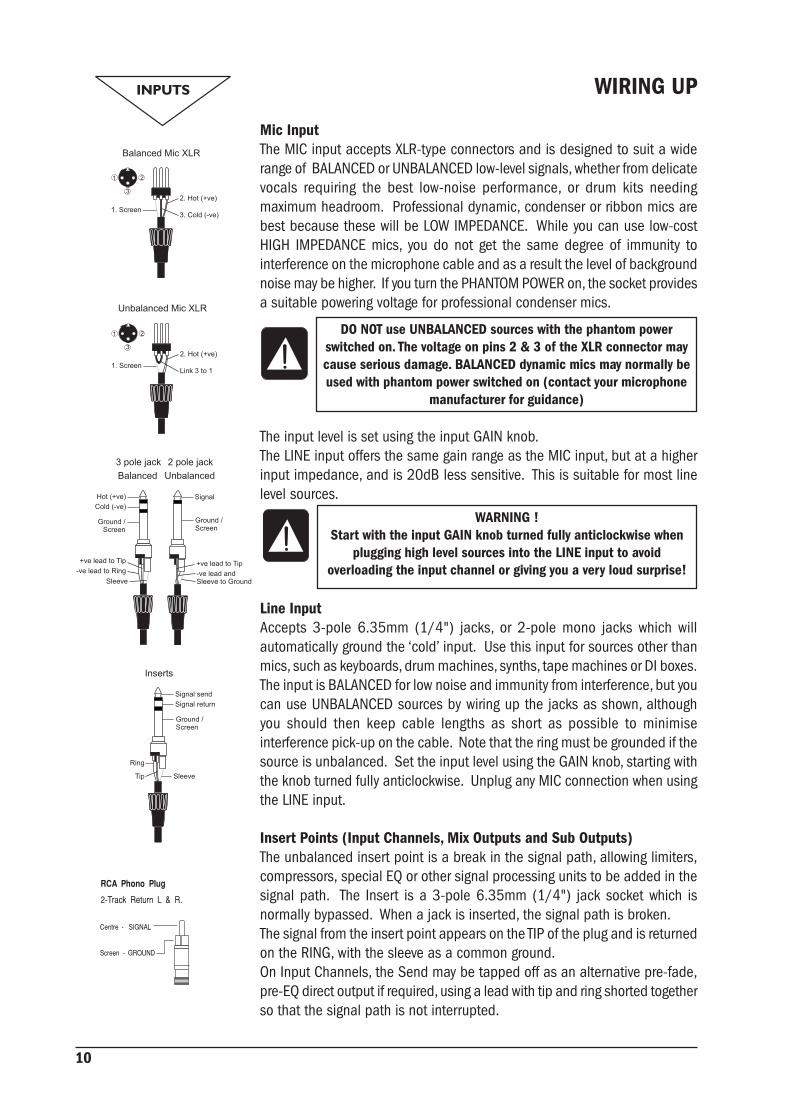
Mic InputThe MIC input accepts XLR-type connectors and is designed to suit a widerange of BALANCED or UNBALANCED low-level signals, whether from delicatevocals requiring the best low-noise performance, or drum kits needingmaximum headroom. Professional dynamic, condenser or ribbon mics arebest because these will be LOW IMPEDANCE. While you can use low-costHIGH IMPEDANCE mics, you do not get the same degree of immunity tointerference on the microphone cable and as a result the level of backgroundnoise may be higher. If you turn the PHANTOM POWER on, the socket providesa suitable powering voltage for professional condenser mics.
The input level is set using the input GAIN knob.The LINE input offers the same gain range as the MIC input, but at a higherinput impedance, and is 20dB less sensitive. This is suitable for most linelevel sources.
Line InputAccepts 3-pole 6.35mm (1/4") jacks, or 2-pole mono jacks which willautomatically ground the ‘cold’ input. Use this input for sources other thanmics, such as keyboards, drum machines, synths, tape machines or DI boxes.The input is BALANCED for low noise and immunity from interference, but youcan use UNBALANCED sources by wiring up the jacks as shown, althoughyou should then keep cable lengths as short as possible to minimiseinterference pick-up on the cable. Note that the ring must be grounded if thesource is unbalanced. Set the input level using the GAIN knob, starting withthe knob turned fully anticlockwise. Unplug any MIC connection when usingthe LINE input.
Insert Points (Input Channels, Mix Outputs and Sub Outputs)The unbalanced insert point is a break in the signal path, allowing limiters,compressors, special EQ or other signal processing units to be added in thesignal path. The Insert is a 3-pole 6.35mm (1/4") jack socket which isnormally bypassed. When a jack is inserted, the signal path is broken.The signal from the insert point appears on the TIP of the plug and is returnedon the RING, with the sleeve as a common ground.On Input Channels, the Send may be tapped off as an alternative pre-fade,pre-EQ direct output if required, using a lead with tip and ring shorted togetherso that the signal path is not interrupted.
WARNING !Start with the input GAIN knob turned fully anticlockwise when
plugging high level sources into the LINE input to avoidoverloading the input channel or giving you a very loud surprise!
DO NOT use UNBALANCED sources with the phantom powerswitched on. The voltage on pins 2 & 3 of the XLR connector maycause serious damage. BALANCED dynamic mics may normally beused with phantom power switched on (contact your microphone
manufacturer for guidance)

11
A ‘Y’ lead may be required to connect to equipment with separate send andreturn jacks as shown below:
Stereo Returns 1 - 4These accept 3-pole 6.35mm (1/4") jacks, or 2-pole mono jacks which willautomatically ground the ‘cold’ input. Use these inputs for sources such askeyboards, drum machines, synths, tape machines or as returns from processingunits. The input is BALANCED for low noise and immunity from interference,but you can use UNBALANCED sources by wiring up the jacks as shown, althoughyou should then keep cable lengths as short as possible to minimise interferencepick-up on the cable. Note that the ring must be grounded if the source isunbalanced.Mono sources can be fed to both paths by plugging into the Left jack only.
2-Track ReturnThese accept RCA phono plugs.
Mix OutputsThe MIX outputs are on XLR’s, wired as shown, and incorporate impedancebalancing, allowing long cable runs to balanced amplifiers and other equipment.
Aux Outputs, Monitor Outputs & Channel Direct OutputsThese outputs are on 3-pole 6.35mm (1/4") jack sockets, wired as shown onthe left, and are balanced, allowing long cable runs to balanced amplifiers andother equipment.
HeadphonesThe PHONES output is a 3-pole 6.35mm (1/4") jack, wired as a stereo outputas shown, ideally for headphones of 150Ω or greater. 8Ω headphones arenot recommended.

12
Polarity (Phase)You will probably be familiar with the concept of polarity in electricalsignals and this is of particular importance to balanced audio signals.Just as a balanced signal is highly effective at cancelling out unwantedinterference, so two microphones picking up the same signal can cancelout, or cause serious degradation of the signal if one of the cables hasthe +ve and -ve wires reversed. This phase reversal can be a real problemwhen microphones are close together and you should therefore alwaystake care to connect pins correctly when wiring audio cables.
Grounding and ShieldingFor optimum performance use balanced connections where possible andensure that all signals are referenced to a solid, noise-free earthing pointand that all signal cables have their screens connected to ground. Insome unusual circumstances, to avoid earth or ground ‘loops’ ensurethat all cable screens and other signal earths are connected to groundonly at their source and not at both ends.If the use of unbalanced connections is unavoidable, you can minimisenoise by following these wiring guidelines:• On INPUTS, unbalance at the source and use a twin screened cable
as though it were balanced.• On OUTPUTS, connect the signal to the +ve output pin, and the
ground of the output device to -ve. If a twin screened cable isused, connect the screen only at the mixer end.
• Avoid running audio cables or placing audio equipment close tothyristor dimmer units or power cables.
• Noise immunity is improved significantly by the use of lowimpedance sources, such as good quality professional microphonesor the outputs from most modern audio equipment. Avoid cheaperhigh impedance microphones, which may suffer from interferenceover long cable runs, even with well-made cables.
Grounding and shielding is still seen as an imprecise art, and thesuggestions above are only guidelines. If your system still hums, an earth/ground loop is the most likely cause. Two examples of how an earth loopcan occur are shown below.
Warning!Under NO circumstances must the AC power mains earth be disconnected
from the mains lead.

13
PROBLEM SOLVINGBasic problem solving is within the scope of any user if a few basic rules are followed.• Get to know the Block Diagram of your console (see page 9).• Get to know what all controls and/or connections in the system are supposed
to do.• Learn where to look for common trouble spots.The Block Diagram is a representative sketch of all the components of the console,showing how they connect together and how the signal flows through the system.Once you have become familiar with the various component blocks you will find theBlock Diagram is quite easy to follow and you will have gained a valuable understandingof the internal structure of the console.Each component has a specific function and only by getting to know what each part issupposed to do will you be able to tell if there is a genuine fault! Many “faults” are theresult of incorrect connection or control settings which may have been overlooked.Basic Troubleshooting is a process of applying logical thought to the signal path throughthe console and tracking down the problem by elimination.• Swap input connections to check that the source is really present. Check both
Mic and Line inputs.• Eliminate sections of the channel by using the insert point to re-route the signal
to other inputs that are known to be working.• Route channels to different outputs or to auxiliary sends to identify problems
on the Master section.• Compare a suspect channel with an adjacent channel which has been set up
identically. Use PFL to monitor the signal in each section.• Insert-point contact problems may be checked by using an insert bypass jack
with tip and ring shorted together as shown below. If the signal appears whenthe jack is inserted it shows that there is a problem with the normalling contactson the jack socket, caused by wear or damage, or often just dirt or dust. Keepa few in your gig tool box.
If in doubt please contact Soundcraft customer support.
PRODUCTS UNDER WARRANTYUK customers should contact their local dealer.Customers outside the UK are requested to contact their territorial distributor who isable to offer support in the local time zone and language. Please see the distributorlistings on our website (www.soundcraft.com) to locate your local distributor.
OUT-OF-WARRANTY PRODUCTSFor out-of-warranty consoles purchased in the United Kingdom, please contact theCustomer Services Department (e-mail: [email protected]) at the factory in PottersBar, Hertfordshire: Telephone +44 (0)1707 665000.For all other out-of-warranty consoles, please contact the appropriate territorialdistributor.When mailing or faxing please remember to give as much information as possible.This should include your name, address and a daytime telephone number. Should youexperience any difficulty please contact Customer Services Department (e-mail:[email protected])

14
CONSOLE CONTROLS
INPUT CHANNEL
1 Mic Input (Rear Connector Panel)The mic input accepts XLR-type connectors and is designed to suit a wide range ofBALANCED or UNBALANCED signals. Professional dynamic, condenser or ribbon micsare best because these will be LOW IMPEDANCE. You can use low-cost HIGH IMPEDANCEmics, but the level of background noise will be higher. Unplug any mics if you want touse the LINE Input. The input level is set using the GAIN knob.
2 PHANTOM POWERMany professional condenser mics need an external powering voltage, normally 48V,known as PHANTOM POWER. This is a method of sending a powering voltage down thesame wires as the mic signal.If you press the appropriate PHANTOM POWER switch down, the XLR socket will providea suitable powering voltage (48V) for professional condenser mics. There are twoswitches: one for channels 1-8, the other is for channels 9-16, they are located towardsthe top of the console’s surface. The adjacent LEDs illuminate when the phantom poweris active.
ONLY connect condenser microphones with the Phantom Power OFF (switchUP), and ONLY turn the Phantom Power on or off with all output faders
DOWN, to prevent damage to the mixer or external devices.TAKE CARE when using unbalanced sources, which may be damaged by the
Phantom Power voltage on pins 2 & 3 of the XLR connector.Balanced dynamic mics and leads can normally be used with phantom power switched
on (contact your microphone manufacturer for guidance).
3 LINE INPUT (Rear Connector Panel)Accepts 3-pole ‘A’ gauge (TRS) jacks. Use this high impedance input for sources otherthan mics, such as keyboards, drum machines, synths, tape machines or guitars. Theinput is BALANCED for low noise and top quality from professional equipment, but youcan use UNBALANCED sources, although you should then keep cable lengths as shortas possible. Unplug anything in the MIC input if you want to use this socket. Set theinput level using the GAIN knob.
4 GAINThis knob sets how much of the source signal is sent to the rest of the mixer. Too high,and the signal will distort as it overloads the channel; too low, and the level of anybackground hiss will be more noticeable and you may not be able to get enough signal

15
level to the output of the mixer.Note that some sound equipment, particularly that intended for domestic use, operates at a lower level (-10dBV) than professional equipment and will therefore need a higher gain setting to give the same outputlevel.See ‘Initial Setup’ on page 31 to learn how to set the GAIN correctly.
5 100Hz HI-PASS FILTERPressing this switch activates a steep 18dB per octave filter which reduces the level of bass frequencies only.Use this in live PA situations to clean up the mix, reducing stage rumble or ‘popping’ from microphones.
6 EQUALISERThe 3 band swept Equaliser (EQ) allows fine manipulation of the frequency bands, and is particularly usefulfor improving the sound in live PA applications where the original signal is often far from ideal and whereslight boosting or cutting of particular voice frequencies can dramatically improve clarity.
HF EQTurn clockwise to boost high (treble) frequencies (12kHz and above) by up to 15dB, adding crispness tocymbals, vocals and electronic instruments. Turn anticlockwise to cut by up to 15dB, reducing hiss or excessivesibilance which can occur with certain types of microphone. Set the knob in the centre-detented positionwhen not required.
MID EQThis pair of knobs work together to form a MID frequency EQ section. The lower knob provides 15dB of boostand cut, just like the HF EQ knob, but the frequency at which this occurs can be set by the upper knob over arange of 150Hz to 3.5kHz. This allows some truly creative improvement of the signal in live situations,because the mid band covers the range of most vocals. Listen carefully as you use these controls together tofind how particular characteristics of, for instance, a vocal signal can be enhanced or reduced. Set the gain(lower) knob to the centre-detented position when not required. Note: Q is set at 1.5.
LF EQTurn clockwise to boost low (bass) frequencies (80Hz and below) by up to 15dB, adding warmth to vocals orextra punch to synths, guitars and drums. Turn anticlockwise to cut low frequencies by up to 15dB forreducing hum, stage rumble or to improve a mushy sound. Set the knob to the centre-detented positionwhen not required.
7 AUX SENDSThese are used to set up separate mixes for FOLDBACK, EFFECTS or recording, and the combination of eachAux Send is mixed to the respective Aux Output at the rear of the mixer. For Effects it is useful for the signalto fade up and down with the fader (this is called POST-FADE), but for Foldback or Monitor feeds it isimportant for the send to be independent of the fader (this is called PRE-FADE). All Aux Sends are muted withthe other channel outputs when the MUTE switch is pressed.Aux 1 is always PRE-FADE, POST EQ, and would typically be used as a foldback or monitor feed. Aux 2 & 3 arenormally POST-FADE, POST-EQ for use as effects sends or additional submixes, but for flexibility Aux 2 may beswitched to PRE-FADE, POST-EQ by pressing the associated PRE switch.
8 FXThe FX control is identical to the post-fade Aux 3, but the signal is sent to the internal bus which feeds theinput of the built-in LEXICON® digital effects processor. The output of the LEXICON processor may be addedto the Mix or Subs and/or Aux 1 or 2 busses.

16
9 PANThis control sets the amount of the channel signal feeding the MIX L & R or SUBL & R busses (see SUB & MIX below), allowing you to move the source smoothlyacross the stereo image. When the control is turned fully right or left you areable to route the signal at unity gain to either left or right outputs individually.A mono sum of the post-fader channel signal is also fed to the Mono output,unaffected by the position of the PAN control.
10 MUTEAll outputs from the channel except inserts and pre-fade Direct outputs areactive when the MUTE switch is released and muted when the switch is down,allowing levels to be pre-set before the signal is required.
11 SUBThe channel signal may be routed to the SUB L & R busses by pressing thisswitch, with the channel signal fed proportionately to left or right depending onthe position of the PAN control.
12 MIXThe channel signal may be routed to the MIX L & R busses by pressing thisswitch, with the channel signal fed proportionately to left or right depending onthe position of the PAN control.
13 SOLO/PKThe FX16ii provides versatile non-destructive PFL (Pre-Fade-Listen) and SOLO-IN-PLACE monitoring, as selected by the SOLO MODE switch on the Mastersection.
PFLWhen the latching SOLO switch is pressed, the pre-fade, post-EQ signal is fedto the headphones, control room output and meters, where it replaces theselected monitor source. The adjacent LED illuminates to identify the selectedchannel and the PFL/AFL LED on the Master section illuminates to warn that aPFL is active. This is a useful way of listening to any required input signalwithout interrupting the main mix, for making adjustments or tracing problems.When the PFL switch is released the LED serves as a PEAK indicator whichilluminates approximately 4dB before clipping to give warning of a possibleoverload. The signal is sampled both pre-insert and after the HF EQ.Note: It is normal for the Peak/PFL LED to go off slowly when the switch ispressed.
SOLO-IN-PLACEIn contrast to PFL, SOLO-IN-PLACE mode allows an individual channel, orselection of channels to be monitored in isolation from the rest of the mix, butat the correct mix levels and with all sends and effects active. With SOLOMODE active, pressing any one or more SOLO switches mutes all channelswhich are not SOLOed, leaving only the selected channels in the mix. When theSOLO switches are released the original mix is restored.
Note that when SOLO MODE is active, pressing any SOLO switch interruptsthe main MIX, and should therefore not be used during live performance.

17
14 FADERThe 100mm FADER allows precise balancing of the various source signals being mixed to the selectedoutputs. You get most control when the input Sensitivity is set up correctly, giving full travel on the fader. Seethe ‘Initial Setup’ section on page 31 for help in setting a suitable signal level.
15 DIRECT OUTPUT (Rear Connector Panel)Each channel has a dedicated Direct Output which allows direct connection to external devices, for exampleto feed Tape Machines or effects units.The pre-fade direct output level may be monitored by pressing the SOLO switch on the appropriate channel(with the mixer in PFL mode) to feed the pre-fade signal to the monitors and the bargraph meters.
16 DIR. PREThe Direct Outputs are normally POST-FADE for use as effects sends or to provide fader control of recordinglevels in a studio recording application. For live recording the outputs can be individually changed to PRE-FADE by pressing this switch, so that the direct output level remains unaffected by fader settings for the mainPA mix.
17 INSERT POINT (Rear Connector Panel)The unbalanced, pre-EQ insert point is a break in the channel signal path, allowing limiters, compressors,special EQ or other signal processing units to be added in the signal path. The Insert is a 3-pole ‘A’ gauge jacksocket which is normally bypassed. When a jack is inserted, the signal path is broken, just before the EQsection. The Send may be tapped off as an alternative pre-fade, pre-EQ direct output if required, using a leadwith tip and ring shorted together so that the signal path is not interrupted.Inserts can also be used to send and return from a multitrack tape machine.

18
MASTER SECTION

19
1 AUX MASTERSEach of the three AUX outputs has a master level control which sets the output level of the combined Auxsignals from the channels, and an associated AFL switch. Just as the Channel PFL switches allow pre-fadelistening, so you can monitor each AUX output after the level control by pressing the AFL switch (when PFLmode is selected by the SOLOMODE switch), allowing you to determine what level is leaving the outputconnector. This routes the AUX output signal to the MONITOR or PHONES, replacing any existing signal whichis selected. The METERS also switch from the selected source to display the PFL/AFL signal and the PFL/AFLLED lights to warn that a PFL or AFL switch is pressed. When you release the switch the Monitor swaps backto the previous source.
2 FX MASTERThe FX master control sets the overall level of the FX sends from the channels before the input of theLEXICON® Digital Effects Processor. An associated AFL switch allows the signal to be monitored in the sameway as the Aux masters (see above).Note: When FX AFL switch is pressed, the meters become the Lexicon Input level indicators.
3 SUB MASTER FADERS & OUTPUTSThe SUB MASTER FADERS set the final level of the SUB L & R outputs. These should normally be set close tothe ‘0’ mark if the input GAIN settings have been correctly set, to give maximum travel on the faders forsmoothest control.
4 SUB TO MIXThe SUB mix may be used to provide alternative outputs from the mixer, or, by pressing SUB TO MIX the SUBL & R master faders may be used as audio subgroups, setting the level of a combination of input channelswhich are added to the main mix under the control of a pair of faders.
5 SUB INSERTSEach unbalanced, pre-fade insert point is a break in its Sub signal path, allowing limiters, compressors,special EQ or other signal processing units to be added in the signal path. The Insert is a 3-pole ‘A’ gauge jacksocket which is normally bypassed. When a jack is inserted, the signal path is broken.
6 MIX MASTER FADERS & OUTPUTSThe MASTER FADERS set the final level of the MIX L & R outputs. These should normally be set close to the‘0’ mark if the input GAIN settings have been correctly set, to give maximum travel on the faders for smoothestcontrol. The MONO SUM OUTPUT carries a mono sum of the Mix L and Mix R output signals.
7 MIX INSERTSEach unbalanced, pre-fade insert point is a break in its Main Mix signal path, allowing limiters, compressors,special EQ or other signal processing units to be added in the signal path. The Insert is a 3-pole ‘A’ gauge jacksocket which is normally bypassed. When a jack is inserted, the signal path is broken.

20
8 STEREO RETURNSFour balanced Stereo Returns are available for the outputs of effects units or other stereo sources and aremixed directly to the AUX and/or MIX/SUB busses at a level set by the respective controls. The left-handcontrol sets the level to a choice of AUX 1 or AUX 2 (AUX 3 or FX in the case of RET 4), depending on thepostion of the adjacent switch. The right-hand control sets the level to MIX or SUB depending on the positionof the adjacent switch (it is effectively a rotary fader).If a mono source is used, plugging into the Left jack only automatically feeds the signal to both Left andRight.
9 EFFECTS RETURNThe Effects Return is similar to the Stereo Returns, but instead of taking an external source this section is fedfrom the output of the internal LEXICON® Digital Effects Processor. Routing is to a choice of AUX 1/2 and/orMIX/SUB.
10 2 TRACK LEVEL CONTROL & INPUTSThe rotary control sets the level of the 2 Track Tape input, which is routed to the headphones, monitor outputsand meters, or directly to the Mix outputs by pressing the adjacent switch (11). These unbalanced inputs, onRCA phono connectors, are ideal to connect the playback of a tape machine for monitoring.
11 2 TRACK TO MIXPressing this switch adds the 2-Track Tape input to the Mix and is an ideal way of feeding pre-show music tothe main outputs in live applications without using up valuable input channels.
12 SOLO MODEThis switch selects either non-destructive AFL/PFL (switch UP), or SOLO-IN-PLACE monitoring (switch DOWN).The two modes are described below:
13 PFL MODEWhen any input channel SOLO switch or master section AFL switch is pressed, the selected signal is fed to theheadphones, control room output and meters, where it replaces the selected monitor source. The PFL/AFLLED illuminates to warn that a PFL is active.This is a useful way of listening to any required input signal without interrupting the main mix, for makingadjustments or tracing problems.
14 SOLO-IN-PLACE MODEIn contrast to PFL, SOLO-IN-PLACE mode allows an individual channel, or selection of channels to be monitoredin isolation from the rest of the mix, but at the correct mix levels and with all sends, pans and effects active.With SOLO MODE active (switch down), pressing any one or more SOLO switches on the input channel mutesall channels which are not SOLOed, leaving only the selected channels in the mix. When the SOLO switchesare released the original mix is restored. The SIP ACTIVE LED warns when SOLO-IN-PLACE is on.
Note that when SOLO MODE is active, pressing any SOLO switch interrupts the main MIX, andshould therefore not be used during live performance.
15 BARGRAPH METERS3-colour peak reading BARGRAPH METERS are provided to monitor the 2TK, MIX or SUB signals, giving you aconstant warning of excessive peaks in the signal which might cause overloading. Aim to keep the signalwithin the amber segments at peak levels for best performance.Similarly, if the output level is too low and hardly registering at all on the meters, the level of background noisemay become significant. Take care to set up the input levels for best performance.

21
When any SOLO or AFL switch is pressed, the L & R meters automatically switch to show the selected PFL/AFLsignal on both meters, in mono.
16 MONITOR SOURCE SELECTThese switches allow a choice source for the Phones, Monitor outputs and meters. Normally the monitorsource is either MIX or SUB (or both, depending on which of the two right-hand switches is selected), butpressing the 2TK switch swaps the monitoring to the 2 Track input. When the switch is released the normalMIX/SUB selection is restored.
17 MONITOR CONTROL & OUTPUTSThis control sets the output level to the MONITOR LEFT & RIGHT outputs without affecting the level to themeters.
18 HEADPHONESThis control sets the level of the monitor signal to the MONITOR PHONES output.
19 MONITOR PHONESThe MONITOR PHONES output appears on a 3-pole 1/4" jack, suitable for headphones with an impedance of150 ohms or higher.

22
Lexicon® FX PROCESSOR
The effects within the console have been designed with both live sound reinforcement and home recording inmind. Featuring the deep, rich reverb algorithms that Lexicon® are renowned for the effects processor offersincreased versatility and high quality effects, all instantly accessible via the extremely intuitive front panelcontrols. The effects processor has 32 programs which are held in two banks of 16 programs which can bestored to allow you to create your own custom effect settings.
Front panel controls include a Program Select knob, Tap Tempo and Store buttons, and three independent‘Adjust’ knobs that provide instant access and control over the most critical parameters for the selectedeffect. The table on page 30 lists the functions of the Parameter knobs for each fx program.
Note: When the console is powered up the program recalled will always be the selected program in BANK A.
FX OPERATION
Select and Load a ProgramTurn the Program Select knob to choose a program. Note that the console has 32 programs which are heldin two banks of 16 programs. There are individual BANK A and BANK B LED’s to indicate which bank iscurrently active. When turning the rotary Program Select knob through 360 degrees (a full rotation) theselected bank will alternate between BANK A and BANK B.
Set Audio Levels
1. Set the gain on the input channel appropriate to the source (vocal microphone, guitar, keyboard, etc.).
2. Set the FX Master level to the 12 o’clock position.
3. Set the FX Send level on the appropriate input channel to the 12 o’clock position.
4. Provide source signal (by speaking or singing into the microphone, playing guitar, keyboard, etc.) on theselected channel.
5. Turn up the FX Send level on the channel until the Red CLIP LED in the FX Panel lights only occasionally. Ifthe red Input LED stays lit, too much signal is being sent to the effect processor; reduce the FX Master or FXSend on the input channel.
6. Adjust the required EFFECTS RETURN level controls and switches to feed the FX processor output to theMix/Sub and/or Aux1/Aux2 busses.
7. To increase or decrease the amount of effect on the signal, adjust the FX Send level on the channel that youwant affected.

23
FX PROCESSOR CONTROLS
20 Tap Tempo Button - Tapping this button twice sets the Delay Time of the selected program. The LED flashesto indicate current tempo. Can be tapped in time with music source to synchronise the delay.
21 Store Button - Stores program modifications to one of the program locations. Press and hold for threeseconds will store the preset in the current location. The LED will flash rapidly during the store operation andthen stay illuminated for 1 second to show the operation is complete.
22 ADJUST 1 - Pre Delay / Time/ Speed Knob - Controls Pre Delay of the reverbs or the first parameter (timeor speed related) of the selected effect.23 ADJUST 2 - Decay / Feedback/Depth Knob - Controls Decay of the reverbs or the second parameter(feedback or depth related) of the selected effect.
24 ADJUST 3 - Variation - Controls Liveliness or Diffusion (depending on the reverb selected) or the thirdparameter of the selected effect.
25 Program Select Knob - Navigates through programs, turning to the required program will initiate theloading of the program which take approximately 1 second. The knob can be rotated clockwise or anticlockwiseand will alternate between BANK A and BANK B every full rotation. The current bank is shown by the illuminatedLED, which flashes if the fx processor is muted. There is a handy aide memoir of the programs printed on thefront panel.
26 Clip LED – This LED illuminates when either the incoming audio or the processed audio (within the effectprocessor) overloads, and causes distortion of the signal.
27 Footswitch Input (not shown on diagram, see page 19) - Using a single pole, momentary footswitchinserted into the FOOTSWITCH input the effects processor can be muted/un-muted.

24
REVERBS
Reverberation (or “reverb” for short) is the complex effect created by the way we perceive sound in anenclosed space. When sound waves encounter an object or boundary, they don’t just stop. Some of thesound is absorbed by the object, but most of the sound is reflected or is diffused. In an enclosed space,reverb is dependent on many features of that space, including the size, shape and the type of materials thatline the walls. Even with closed eyes, a listener can easily tell the difference between a closet, a locker roomand a large auditorium. Reverb is a natural component of the acoustic experience, and most people feel thatsomething is missing without it.
Hall ReverbA Hall is designed to emulate the acoustics of a concert hall – a space large enough to contain an orchestraand an audience. Because of the size and characteristics, Halls are the most natural-sounding reverbs,designed to remain “behind” the direct sound – adding ambience and space, but leaving the source unchanged.This effect has a relatively low initial echo density which builds up gradually over time. Vocal Hall and DrumHall reverbs are specifically tailored for those uses. Vocal Hall has as lower overall diffusion which works wellwith program material that has softer initial transients like a voice. Drum Hall has a higher diffusion settingwhich is necessary to smooth out faster transient signals found in drums and percussion instruments. Inaddition to general instrumental and vocal applications, the Hall program is a good choice for giving separatelyrecorded tracks the sense of belonging to the same performance.
Plate ReverbA Plate reverb is a large, thin sheet of metal suspended upright under tension on springs. Transducers attachedto the plate transmit a signal that makes the plate vibrate, causing sounds to appear to be occurring in alarge, open space. The Plates in the FX processor model the sound of metal plates with high initial diffusionand a relatively bright, colored sound. Plate reverbs are designed to be heard as part of the music, mellowingand thickening the initial sound. Plate reverbs are often used to enhance popular music, particularly percussion.
Room ReverbRoom produces an excellent simulation of a very small room which is useful for dialog and voiceoverapplications. Room is also practical when used judiciously for fattening up high energy signals like electricguitar amp recordings. Historically, recording studio chambers were oddly shaped rooms with a loudspeakerand set of microphones to collect ambience in various parts of the room.
Chamber ReverbChamber programs produce even, relatively dimensionless reverberation with little color change as sounddecays. The initial diffusion is similar to the Hall programs. However, the sense of size and space is much lessobvious. This characteristic, coupled with the low color of the decay tail, makes these programs useful on awide range of material - especially the spoken voice, to which Chamber programs add a noticeable increasein loudness with low color.
Gated ReverbGated reverb is created by feeding a reverb, such as a metal plate, through a gate device. Decay Time is setto instant, while Hold Time varies duration and sound. The Gated reverb provides a fairly constant sound withno decay until the reverb is cut off abruptly. This program works well on percussion — particularly on snare andtoms; be sure to experiment with other sound sources as well.
Reverse ReverbReverse reverb works in the opposite fashion from normal reverb. Whereas a normal reverb has the loudestseries of reflections heard first that then become quieter over time, the Reverse reverb has the softest reflections

25
(essentially the tail of the reverb) heard first, and then grows louder over time until they abruptly cut off.
Ambience ReverbAmbience is used to simulate the effect of a small or medium sized room without noticeable decay. It is oftenused for voice, guitar or percussion.
Studio ReverbMuch like Room reverb, Studio produces an excellent simulation of smaller, well controlled acoustic spaces,characteristic of the main performance areas in recording studios. Studio is also useful with dialog andvoiceover applications as well as individual instrument and electric guitar tracks.
Arena ReverbArena reverb emulates a huge physical space such as an indoor sports venue or stadium. The characteristicsof Arena reverb are long secondary reflection times and a reduced amount of high frequency content. Arenais a mostly mid- and low frequency dominant reverb, and is an ideal selection for “special effect” typeapplications that require extremely long reverb times. It is not a good choice for a very busy mix, since it canreduce intelligibility.
Spring ReverbA Spring reverb is created by a pair of piezoelectric crystals—one acting as a speaker and the other acting asa microphone— connected by a simple set of springs. The characteristic ‘boing’ of a spring is an importantcomponent of many classic rock and rockabilly guitar sounds.
REVERB CONTROLS
Pre DelayCreates an additional time delay between the source signal and the onset of reverberation. This control is notintended to precisely mimic the time delays in natural spaces, as the build-up of reverberation is gradual, andthe initial time gap is usually relatively short. For the most natural effect, the Pre Delay values should be setin the range of 10-25 milliseconds. However, if a mix is very busy or overly cluttered, increasing the Pre Delaytime may help clarify it, and set each instrument apart from each other.
DecayControls the amount of time the reverb can be heard. Higher settings increase reverberation times which areusually associated with larger acoustical environments, but can decrease intelligibility. Lower settings shortenreverb times and should be used when a smaller apparent space or a more subtle effect is desired.
LivelinessAdjusts the amount of high frequency content in the reverberation tails. Higher settings increase high frequencyresponse, creating brighter reverbs; lower settings create darker reverbs with more bass frequency emphasis.
DiffusionControls the initial echo density. High settings of Diffusion result in high initial echo density, and low settingscause low initial density. In a real-world situation, irregular walls cause high diffusion, while large flat wallscause low diffusion. For drums and percussion, try using higher Diffusion settings.
ShapeThis control helps give a sense of both room shape and room size. Low values for Shape keep the majority ofsound energy in the early part of the reverb tail. High values move the energy to later in the reverb, and arehelpful in creating the sense of a strong rear wall or “backslap.

26
BoingThis is a unique parameter to the Spring reverb, designed to increase or decrease the amount of spring rattlethat is a physical characteristic of spring tank reverbs.
DELAYSDelays repeat a sound a short time after it first occurs. Delay becomes echo when the output is fed back intothe input (feedback). This turns a single repeat into a series of repeats, each a little softer than the last.
Studio DelayThe Studio Delay features up to 2.5 seconds of stereo delay and offers a built-in ducker that attenuates thedelay output whenever signal is present at the input. This can be used to keep the original signal from beingmuddied up by delay repeats.
Digital DelayThe Digital Delay is the cleanest, most accurate of the delay programs, with up to 5 seconds of mono delayand the built-in ducking feature.
Tape DelayIn the days before digital, delays were created using a special tape recorder in which the magnetic recordingtape was looped, with closely-spaced recording and playback heads. The delay effect was created by thetape moving in the space between the record and playback heads – while delay time was adjusted bychanging the speed of the tape loop. Although very musical-sounding, wow and flutter combined with asignificant loss of high frequencies, and to some extent also low frequencies, are all elements commonlyassociated with tape recordings. The Tape Delay offers up to 5 seconds of mono delay.
Pong DelayThis delay effect pans the delay repeats from left to right, while the input signal remains at its original (center)position. Pong Delay offers up to 5 seconds of mono delay time.
Modulated DelayThe Modulated Delay is enhanced by an LFO (low frequency oscillator) that produces a chorusing effect onthe delay repeats. This is a great delay for guitar and instrument passages that need that “special something.”The Modulated Delay features up to 2.5 seconds of stereo modulated delay.
Reverse DelayThis delay effect emulates the old studio trick of flipping a tape over, playing it backwards through a tapedelay, and recording the effect. The delays “build up” from softer to louder – creating the sensation that thedelays come before the signal. Up to 5 seconds of mono delay time are available.
DELAY CONTROLS
Time RangeControls the length of the delay relative to Tap Tempo. At the 12 o’clock position, delay repeats are synchronouswith the Tempo light (represented by a Quarter Note); lower values create faster repeats, higher valuesincrease the time between repeats. Range 0-72. See the Effects Data Chart for exact note values.
FeedbackControls the number of delay repeats by feeding the delay output signal back into the delay input. Thiscreates a series of delay repeats, each slightly attenuated until they become inaudible. Higher settings create

27
more repeats; lower settings reduce the number of repeats. When this knob is turned fully clockwise, itengages Repeat Hold – delay repeats play back in an infinite loop, but no further input signal is introducedinto the delay effect. Repeat Hold is available only on Studio, Digital and Pong Delay.
Ducker ThresholdStudio and Digital delays offer a “ducking” feature, which causes the delay repeats to attenuate (or get softer)by -6dB when live (or input) signal is present. This allows the delay to remain as an effect, and not clash withthe original signal. The higher this value is set, the louder an input signal must be for the ducking to takeplace.
SmearThis parameter controls the amount of “smear,” or signal degradation and frequency loss. Particularly evidentin the Tape Delay, the higher the setting, the more each delay repeat loses intelligibility compared to theoriginal signal.
Tap RatioTap Ratio sets the length between the first and second tap repeats of the Pong Delay. With this control set at12 o’clock, repeats are evenly alternated between left and right channels. As this knob is turned counter-clockwise, the first tap occurs earlier and the second tap occurs later than they did at the 12 o’clock position.When the knob is turned clockwise, the first tap occurs later and the second tap occurs earlier.
DepthThis controls the intensity of modulation, or “depth” in the Modulated Delay. Lower settings produce a moresubtle effect, while higher values give a more “seasick” feeling.
Tempo ButtonTapping this button twice sets the delay times. The Tempo button LED flashes the tempo tapped in, and delaytaps will be synchronized to the flashing LED. Use the Time Range knob to increase or decrease delay timesafter tapping in a tempo.
Note: When Delay Feedback is at maximum (fully clockwise) in some programs the mode changes to hold theaudio in a constant loop. This is indicated in the Effects Data Chart as “+H”.
MODULATED EFFECTS
ChorusChorus creates a lush, full sound by combining two or more signals together where one is unaffected and theother signals vary in pitch very slightly over time. Chorus is commonly used to fatten up tracks and to addbody to guitars without coloring the original tone. Chorus can also be used with discretion to thicken a vocaltrack.
Adjust 1: Speed Controls the modulation rate of the Chorus effect. Lower settings are subtle, while highervalues are much more pronounced.Adjust 2: Depth Controls the amount of pitch shifting for each voice. Lower settings provide subtle thickeningand warmth to a track, while higher settings give a more pronounced, multi-voice effect.Adjust 3: Voices Controls the number of additional Chorus voices. Up to 8 voices can be added, continuouslyvariable in 100 individual steps.

28
FlangerThis effect was originally created by simultaneously recording and playing back two identical programs on twotape recorders, then using hand pressure against the flange of the tape reels to slow down first one machine,then the other. The result was a series of changing phase cancellations and reinforcements, with characteristicswishing, tunneling, and fading sounds.
Adjust 1: Speed Controls the modulation rate of the Flanger effect.Adjust 2: Depth Controls the intensity of the Flanger effect. Lower settings provide a slight “whooshing”sound while higher settings provide a much more dramatic “jet airplane” sound.Adjust 3: Regeneration This knob controls the amount of modulated signal being fed back into the input,creating feedback. Higher amounts add a metallic resonance to the signal.
PhaserThe Phaser automatically moves frequency notches up and down the spectrum of the signal by means of alow frequency oscillator (LFO), creating an oscillating “comb-filter” type effect. This effect is very userful onkeyboards (especially pad presets) and guitars.
Adjust 1: Speed Controls the modulation rate of the Phaser effect.Adjust 2: Depth Controls the intensity of the Phaser effect.Adjust 3: Regeneration This knob controls the amount of modulated signal being fed back into the input,creating feedback. Higher amounts add more resonance to the effect signal.
Tremelo/PanTremolo and Panner create rhythmic changes in signal amplitude. Tremolo affects both channel’s amplitudesimultaneously, while the Panner affects the amplitude of each channel in an alternating manner.
Adjust 1: Speed Controls the modulation rate of the Tremolo/Panner.Adjust 2: Depth Controls the intensity of the volume amplitude change.Adjust 3: Phase Controls whether the amplitude change occurs in both channels simultaneously (Tremolo)or alternates between channels (Panner).
RotaryRotary speaker cabinets were designed to provide a majestic vibrato/choir effect for electronic theater andchurch organs. The most well known rotary speaker is the Leslie™ Model 122, which has two counter- rotatingelements: a high-frequency horn and a low-frequency rotor with slow and fast speeds. The sound generatedas the spinning elements change speed is truly magical. The swirling, spacious effect is difficult to describe– but clearly recognizable. The Rotary effect is modeled after a Leslie-style cabinet. The input signal is splitinto high and low-frequency bands. The rotation effect is created by a synchronized combination of pitchshifting, tremolo, and panning. Like the physical cabinet, the high (horn) and low (rotor) frequencies are“spun” in opposite directions. Horn and rotor speeds are independent, and designed with acceleration anddeceleration characteristics to simulate the inertia of the original mechanical elements. A virtual requirementfor organ music, Rotary also sounds remarkable with guitar and electric piano rhythm parts. In fact, theseprograms are great alternatives to the Chorus and Tremolo effects for any sound source.
Adjust 1: Speed Controls the modulation rate of both rotary speakers. The lower frequencies rotate at aslower speed than the high frequencies.Adjust 2: Doppler Increases or decreases the Doppler pitch effect that is created by the physics of a rotatingspeaker.Adjust 3: Stereo Spread Increases or decreases the stereo imaging of the Rotary effect.

29
VibratoVibrato is obtained by smoothly varying the pitch of the signal just sharp and flat of the original at a determinedrate. Vibrato Stereo (Wet only) Rotary Mono (Wet only) Tremolo/Pan Stereo (Wet only)Adjust 1: Speed Controls the modulation rate of Vibrato.Adjust 2: Depth Controls the maximum amount of pitch shift. Lower settings result in a mere “warble,” whilehigher settings produce a more exaggerated “wow” sound.Adjust 3: Phase This control sets left and right channel waveforms out of phase, resulting in a leftto- rightpanning motion. This effect shifts the frequency spectrum of the input signal. Altering the pitch of a soundproduces a wide range effects - from subtle detunes to full interval shifts up or down a two octave range.
FACTORY RESET
Use this function if you want to erase all program data and restore the effects processor to its factory state.To perform a Factory Reset press and hold the STORE button while powering up the console. Once theeffects processor has initialized (after three seconds), then release the STORE button and the effects processorwill be restored to its factory state.

30
EFFECTS DATA CHARTN
oN
AM
EA
DJ
US
T1
VA
LU
ER
AN
GE
AD
JU
ST
2V
AL
UE
RA
NG
EA
DJ
US
T3
VA
LU
ER
AN
GE
FIX
ED
1V
AL
UE
FIX
ED
2V
AL
UE
FIX
ED
3V
AL
UE
RO
UT
ING
1S
MA
LL
HA
LL
PR
ED
EL
AY
10
ms
0-1
00
ms
DE
CA
Y1
.0s
0-9
9L
IVE
LIN
ES
S7
50
-99
2L
AR
GE
HA
LL
PR
ED
EL
AY
20
ms
0-2
00
ms
DE
CA
Y2
.0s
0-9
9L
IVE
LIN
ES
S3
50
-99
3V
OC
AL
HA
LL
PR
ED
EL
AY
10
ms
0-2
00
ms
DE
CA
Y1
.0s
0-9
9L
IVE
LIN
ES
S6
50
-99
4D
RU
M H
AL
LP
RE
DE
LA
Y1
0m
s0
-10
0m
sD
EC
AY
0.8
s0
-99
LIV
EL
INE
SS
75
0-9
9
5S
MA
LL
PL
AT
EP
RE
DE
LA
Y2
ms
0-1
00
ms
DE
CA
Y1
.0s
0-9
9L
IVE
LIN
ES
S9
00
-99
6L
AR
GE
PL
AT
EP
RE
DE
LA
Y2
ms
0-2
00
ms
DE
CA
Y1
.75
s0
-99
LIV
EL
INE
SS
90
0-9
9
7V
OC
AL
PL
AT
EP
RE
DE
LA
Y1
0m
s0
-20
0m
sD
EC
AY
1.0
s0
-99
LIV
EL
INE
SS
65
0-9
9
8D
RU
M P
LA
TE
PR
ED
EL
AY
10
ms
0-1
00
ms
DE
CA
Y1
.0s
0-9
9L
IVE
LIN
ES
S7
50
-99
9R
OO
MP
RE
DE
LA
Y2
ms
0-1
00
ms
DE
CA
Y4
00
ms
0-9
9L
IVE
LIN
ES
S5
00
-99
10
ST
UD
IOP
RE
DE
LA
Y5
ms
0-1
00
ms
DE
CA
Y5
00
ms
0-9
9L
IVE
LIN
ES
S7
00
-99
11
CH
AM
BE
RP
RE
DE
LA
Y0
ms
0-1
00
ms
DE
CA
Y1
.2s
0-9
9L
IVE
LIN
ES
S6
00
-99
12
AM
BIE
NC
EP
RE
DE
LA
Y0
ms
0-1
00
ms
DE
CA
Y4
00
ms
0-9
9L
IVE
LIN
ES
S7
00
-99
13
AR
EN
AP
RE
DE
LA
Y2
5m
s0
-20
0m
sD
EC
AY
2.7
5s
0-9
9L
IVE
LIN
ES
S6
00
-99
14
GA
TE
DP
RE
DE
LA
Y0
ms
0-2
00
ms
DE
CA
Y3
00
ms
0-9
9D
IFF
US
ION
25
0-9
9
15
RE
VE
RS
EP
RE
DE
LA
Y2
00
mS
0-2
00
ms
DE
CA
Y0
0-9
9D
IFF
US
ION
50
0-9
9
16
SP
RIN
GP
RE
DE
LA
Y0
0-1
00
ms
DE
CA
Y1
.75
s0
-99
BO
ING
35
0-9
9
17
ST
UD
IO D
EL
AY
TIM
E R
AN
GE
27
5m
s2
0m
s-2
.5s
FE
ED
BA
CK
15
0-9
9+
HD
UC
K T
HR
ES
HO
LD
-6d
B-7
0-0
dB
18
DIG
ITA
L D
EL
AY
TIM
E R
AN
GE
80
0m
s2
0m
s-5
.0s
FE
ED
BA
CK
20
0-9
9+
HD
UC
K T
HR
ES
HO
LD
-8d
B-7
0-0
dB
19
TA
PE
DE
LA
YT
IME
RA
NG
E5
00
ms
20
ms-5
.0s
FE
ED
BA
CK
24
0-9
9S
ME
AR
25
0-9
9
20
PO
NG
DE
LA
YT
IME
RA
NG
E1
.0s
20
ms-5
.0s
FE
ED
BA
CK
30
0-9
9+
HT
AP
RA
TIO
1:1
0-2
3
21
MO
D D
EL
AY
TIM
E R
AN
GE
34
5m
s2
0m
s-2
.5s
FE
ED
BA
CK
25
0-9
9M
OD
DE
PT
H7
50
-99
22
RE
VE
RS
E D
EL
AY
TIM
E R
AN
GE
50
0m
s2
0m
s-2
.5s
FE
ED
BA
CK
00
-99
SM
EA
R5
00
-99
23
CH
OR
US
SP
EE
D2
50
-99
DE
PT
H7
50
-99
VO
ICE
S5
00
-99
24
FL
AN
GE
RS
PE
ED
15
0-9
9D
EP
TH
25
0-9
9R
EG
EN
ER
AT
ION
80
0-9
9
25
PH
AS
ER
SP
EE
D2
50
-99
DE
PT
H7
50
-99
RE
GE
NE
RA
TIO
N8
00
-99
26
TR
EM
EL
O/P
AN
SP
EE
D4
00
-99
DE
PT
H8
00
-99
PH
AS
E5
00
-99
27
RO
TA
RY
SP
EE
D5
00
-99
DO
PP
LE
R6
00
-99
SP
RE
AD
99
0-9
9
28
VIB
RA
TO
SP
EE
D3
00
-99
DE
PT
H3
00
-99
PH
AS
E8
00
-99
29
RE
V/D
EL
SH
OR
TT
IME
RA
NG
E2
75
ms
20
ms-2
.5s
FE
ED
BA
CK
15
0-9
9+
HD
EC
AY
0.7
5S
0-9
9L
IVE
LIN
ES
S6
0P
RE
DE
LA
Y2
ms
DU
CK
TH
RE
SH
OL
D-6
dB
SE
RIA
L :
DE
LA
Y T
HE
N R
EV
ER
B
30
RE
V/D
EL
LO
NG
TIM
E R
AN
GE
80
0m
s2
0m
s-2
.5s
FE
ED
BA
CK
20
0-9
9+
HD
EC
AY
2.0
S0
-99
LIV
EL
INE
SS
40
PR
ED
EL
AY
10
ms
DU
CK
TH
RE
SH
OL
D-8
dB
SE
RIA
L :
DE
LA
Y T
HE
N R
EV
ER
B
31
PH
AS
E D
EL
AY
TIM
E R
AN
GE
50
0m
s2
0m
s-2
.5s
FE
ED
BA
CK
20
0-9
9+
HS
PE
ED
25
0-9
9D
EP
TH
75
RE
GE
NE
RA
TIO
N8
0D
UC
K T
HR
ES
HO
LD
-8d
BS
ER
IAL
: D
EL
AY
TH
EN
PH
AS
E
32
RO
TA
RY
DE
LA
YT
IME
RA
NG
E5
00
ms
20
ms-2
.5s
FE
ED
BA
CK
20
0-9
9+
HS
PE
ED
50
0-9
9D
OP
PL
ER
60
SP
RE
AD
99
DU
CK
TH
RE
SH
OL
D-8
dB
SE
RIA
L :
DE
LA
Y T
HE
N R
OT
AR
Y
Note
+H
= re
peat
hol
d fu
nctio
n(s
ee p
age
27 1
st p
arag
raph
)

31
USING YOUR CONSOLEThe final output from your sound system can only ever be as good as theweakest link in the chain, and especially important is the quality of thesource signal because this is the starting point of the chain. Just as youneed to become familiar with the control functions of your mixer, so youmust recognise the importance of correct choice of inputs, microphoneplacement and input channel settings. However, no amount of careful settingup can take account of the spontaneity and unpredictability of liveperformance. The mixer must be set up to provide “spare” control range tocompensate for changing microphone position and the absorption effectof a large audience (different acoustic characteristics from soundcheck toshow).
MICROPHONE PLACEMENTCareful microphone placement and the choice of a suitable type ofmicrophone for the job is one of the essentials of successful soundreinforcement. The diagrams on the left show the different pick-up patternsfor the most common types of microphone. Cardioid microphones aremost sensitive to sound coming from in front, and hypercardioidmicrophones offer even greater directivity, with a small amount of pickupbehind the microphone. These types are ideal for recording vocalists orinstruments, where rejection of unwanted sounds and elimination offeedback is important. The aim should be to place the microphone asclose as physically possible to the source, to cut out unwanted surroundingsounds, allow a lower gain setting on the mixer and avoid feedback. Also awell chosen and well placed microphone should not need any appreciableequalisation.There are no exact rules - let your ears be the judge. In the end, theposition that gives the desired effect is the correct position!
INITIAL SETUPOnce you have connected up your system (see the sections on connectionand wiring earlier in this manual for guidance) you are ready to set initialpositions for the controls on your mixer.Set up individual input channel as follows:• Connect your sources (microphone, keyboard etc.) to the required
inputs.WARNING: Phantom powered mics should be connected before the+48V is switched on. Ensure the PA system is OFF when switchingphantom power on or off.
• Set Master faders at 0, input faders at 0, and set power amplifierlevels to about 70%.
• Provide a typical performance level signal and press the PFL buttonon the first channel, monitoring the level on the bargraph meters.
• Adjust the input gain until the meter display is in the amber section,with occasional peaks to the first red LED at a typical maximumsource level. This allows sufficient headroom to accommodate peaksand establishes the maximum level for normal operation (but seenote below).
• Repeat this procedure on other channels as required. As more

32
channels are added to the mix, the meters may move into the red section. Adjustthe overall level using the Master Faders if necessary.
• Listen carefully for the characteristic sound of “feedback”. If you cannot achievesatisfactory input level setting without feedback, check microphone and speakerplacement and repeat the exercise. If feedback persists, it may be necessary touse a Graphic Equaliser to reduce the system response at particular resonantfrequencies.
Note:The initial settings should only be regarded as a starting point for your mix. It is importantto remember that many factors affect the sound during a live performance, for instancethe size of the audience!You are now ready to start building the mix and this should be done progressively,listening carefully for each component in the mix and watching the meters for any hintof overload. If this occurs, back off the appropriate Channel Fader slightly until the levelis out of the red segments, or adjust the Master Faders.Remember that the mixer is a mixer, not an amplifier. Increasing the overall level is thejob of the amplifier, and if it is impossible to provide adequate level, it is probable thatthe amplifier is too small for the application. Choose your amplifier carefully, and donot try to compensate for lack of power by using the mixer to increase output level.
Note:The level of any source signal in the final output is affected by many factors, principallythe Input Gain control, Channel Fader and Mix Faders. You should try to use only asmuch microphone gain as required to achieve a good balance between signals, withthe faders set as described above.If the input gain is set too high, the channel fader will need to be pulled down too far incompensation to leave enough travel for successful mixing and there is a greater risk offeedback because small fader movements will have a very significant effect on outputlevel. Also there will be a chance of distortion as the signal overloads the channel andcauses clipping.If the gain is set too low, you will not find enough gain on the faders to bring the signalup to an adequate level, and backgound hiss will be more noticeable.This is illustrated below:

33
APPLICATIONS
APPLICATION 1 - LIVE SOUND REINFORCEMENT

34
APPLICATION 2 - RECORDING

35
APPLICATION 3 - INSTALLATION

36
APPLICATION 4 - PLACE OF WORSHIP

37
APPLICATION 5 - ON-LOCATION BROADCASTING

38
APPLICATION 6 - POST-PRODUCTION VIDEO EDITING

39
APPLICATION 7 - MULTIMEDIA

40
APPLICATION 8 - CONFERENCE PA

41
MARKUP SHEETYou may freely copy this page, and use it to record the settings used for particular applications/gigs.

42
TYPICAL CONNECTING LEADS

43

44
REPOSITIONING THE REAR PANEL FOR RACKMOUNTING
Befo
re s
tart
ing,
dis
conn
ect
all
lead
s fr
om t
he c
onso
le,
INCL
UDI
NG T
HE
MAI
NS L
EAD.
1 Re
mov
e Co
nnec
tor P
anel
fixin
g sc
rews
.2
Rem
ove
Cove
r Pan
el fi
scre
ws.
3 Re
mov
e Fr
ame
Sect
ion
fixin
g sc
rews
.4
Rem
ove
Fram
e Se
ctio
n.5
Swap
Con
nect
or P
anel
and
Cov
er P
anel
pos
ition
s, le
avin
gal
l int
erna
l cab
les
conn
ecte
d.6
Refit
all
item
s in
rev
erse
seq
uenc
e, t
akin
g ca
re t
hat
noin
tern
al c
able
s ar
e tra
pped
ben
eath
the
pane
ls.

45
DIMENSIONS

46
FX16ii TYPICAL SPECIFICATIONS
Frequency ResponseMic / Line Input to any Output ..............................................+/-1dB, 20Hz – 20kHz
T.H.D.Mic Sensitivity -30dBu, +14dBu @ Mix output ................................< 0.09% @ 1kHz
NoiseMic Input E.I.N. (maximum gain) ..............................………..-127dBu (150Ω source)Aux, Mix and Masters (@ 0dB, faders down)......................................………< -84dBu
Crosstalk (@ 1kHz)Channel Mute...............................................................................................> 96dBFader Cut-off (rel +10 mark).........................................................................> 96dBAux Send Pots Offness..................................................................................> 86dB
EQ (Mono inputs)HF ..................................................................................................12kHz, +/-15dBMF (swept)........................................................................150Hz – 3.5kHz, +/-15dBLF......................................................................................................80Hz, +/-15dBQ.........................................................................................................................1.5
Power Consumption...........................................................................Less than 40W
Operating ConditionsTemperature Range.................................................................................5°C to 40°C
Input & Output LevelsMic Input ...............................................................................................+15dBu maxLine Input...............................................................................................+30dBu maxStereo Input ...........................................................................................+30dBu maxMix Output .............................................................................................+20dBu maxHeadphones (@150 Ω) .................................................................................300mW
Input & Output ImpedancesMic Input .............................................................................................................2kΩLine Input ..........................................................................................................10kΩStereo Input ...................................................................65kΩ (stereo), 35kΩ (mono)Outputs ..........................................................150Ω (balanced), 75Ω (unbalanced)
E. & O.E.

47
WARRANTY
1 Soundcraft is a trading division of Harman International Industries Ltd .End User means the person who first puts the equipment into regular operation.Dealer means the person other than Soundcraft (if any) from whom the End User purchased theEquipment, provided such a person is authorised for this purpose by Soundcraft or its accreditedDistributor.Equipment means the equipment supplied with this manual.
2 If within the period of twelve months from the date of delivery of the Equipment to the End User itshall prove defective by reason only of faulty materials and/or workmanship to such an extent thatthe effectiveness and/or usability thereof is materially affected the Equipment or the defectivecomponent should be returned to the Dealer or to Soundcraft and subject to the following condi-tions the Dealer or Soundcraft will repair or replace the defective components. Any componentsreplaced will become the property of Soundcraft.
3 Any Equipment or component returned will be at the risk of the End User whilst in transit (both toand from the Dealer or Soundcraft) and postage must be prepaid.
4 This warranty shall only be valid if:a) the Equipment has been properly installed in accordance with instructions contained inSoundcraft’s manual; andb) the End User has notified Soundcraft or the Dealer within 14 days of the defect appearing;andc) no persons other than authorised representatives of Soundcraft or the Dealer have effectedany replacement of parts maintenance adjustments or repairs to the Equipment; andd) the End User has used the Equipment only for such purposes as Soundcraft recommends,with only such operating supplies as meet Soundcraft’s specifications and otherwise in all respectsin accordance with Soundcraft’s recommendations.
5 Defects arising as a result of the following are not covered by this Warranty: faulty or negligenthandling, chemical or electro-chemical or electrical influences, accidental damage, Acts of God,neglect, deficiency in electrical power, air-conditioning or humidity control.
6 The benefit of this Warranty may not be assigned by the End User.
7 End Users who are consumers should note their rights under this Warranty are in addition to and donot affect any other rights to which they may be entitled against the seller of the Equipment.

48