user instructions installation polychem m-series … · magnetic drive pcn=71569218 07-11 (e)...
TRANSCRIPT
USER INSTRUCTIONS
PolyChem M-series Pumps ISO and ANSI Installation
Operation Maintenance Foot mounted, PFA lined , chemical process pumps with
magnetic drive
PCN=71569218 07-11 (E) (incorporating P-30-503-E) Original instructions.
These instructions must be read prior to installing, operating, using and maintaining this equipment.

USER INSTRUCTIONS PolyChem M-SERIES ENGLISH 71569218 07-11
flowserve.com Page 2 of 60
®
CONTENTS Page
Page
1 INTRODUCTION AND SAFETY .......................... 4 1.1 General ............................................................ 4 1.2 CE marking and approvals .............................. 4 1.3 Disclaimer ........................................................ 4 1.4 Copyright ......................................................... 4 1.5 Duty conditions ................................................ 4 1.6 Safety .............................................................. 5 1.7 Nameplate and safety labels ........................... 8 1.8 Specific machine performance ........................ 8 1.9 Noise level ....................................................... 9
2 TRANSPORT AND STORAGE .......................... 10 2.1 Consignment receipt and unpacking ............. 10 2.2 Handling ........................................................ 10 2.3 Lifting ............................................................. 10 2.4 Storage .......................................................... 11 2.5 Recycling and end of product life .................. 11
3 DESCRIPTION ................................................... 12 3.1 Configurations ............................................... 12 3.2 Nomenclature ................................................ 12 3.3 Design of major parts .................................... 12 3.4 Performance and operation limits .................. 13
4 INSTALLATION .................................................. 15 4.1 Location ......................................................... 15 4.2 Part assemblies ............................................. 15 4.3 Foundation ..................................................... 15 4.4 Grouting ......................................................... 17 4.5 Initial alignment – Long-coupled.................... 18 4.6 Piping ............................................................. 18 4.7 Electrical connections .................................... 25 4.8 Final shaft alignment check – Long-coupled . 25 4.9 Protection systems ........................................ 25
5 COMMISSIONING, STARTUP, OPERATION AND SHUTDOWN .............................................. 26
5.1 Pre-commissioning procedure ....................... 26 5.2 Pump lubricants ............................................. 26 5.3 Direction of rotation ....................................... 28 5.4 Guarding ........................................................ 28 5.5 Priming and auxiliary supplies ....................... 29 5.6 Starting the pump .......................................... 29 5.7 Running or operation ..................................... 30 5.8 Stopping and shutdown ................................. 31 5.9 Hydraulic, mechanical and electrical duty ..... 31
6 MAINTENANCE ................................................. 31 6.1 Maintenance schedule .................................. 32 6.2 Spare parts .................................................... 33 6.3 Recommended spares and consumable items
33 6.4 Tools required ................................................ 33 6.5 Fastener torques ........................................... 35 6.6 Impeller ......................................................... 35 6.7 Pump removal and disassembly ................... 37 6.8 Examination of parts ..................................... 44 6.9 Assembly of pump ........................................ 47
7 FAULTS; CAUSES AND REMEDIES ................ 52
8 PARTS LIST AND DRAWINGS ......................... 55 8.1 PolyChem Group A and 1 Close Coupled ..... 55 8.2 PolyChem Group A and 1 Long Coupled ...... 55 8.3 PolyChem Group B and 2 Close Coupled .... 56 8.4 PolyChem Group B and 2 Long Coupled ..... 56 8.5 PolyChem Group A and 1 ............................. 57 8.6 PolyChem Group B and 2 ............................. 57
9 CERTIFICATION ................................................ 58
10 OTHER RELEVANT DOCUMENTATION AND MANUALS .......................................................... 58
10.1 Supplementary User Instructions .......... 58 10.2 Change notes ........................................ 58 10.3 Additional sources of information .......... 58

USER INSTRUCTIONS PolyChem M-SERIES ENGLISH 71569218 07-11
flowserve.com Page 3 of 60
®
INDEX Page
Page
Additional sources of information (10.3) 58 Assembly of pump (6.9) 47 CE marking and approvals (1.2) 4 Change notes (10.2) 58 Configurations (3.1) 12 Consignment receipt and unpacking (2.1) 10 Copyright (1.4) 4 Design of major parts (3.3) 12 Direction of rotation (5.3) 28 Disclaimer (1.3) 4 Drawing Group A and 1 Close Coupled (8.1) 55 Drawing Group A and 1 Long Coupled (8.2) 55 Drawing Group B and 2 Close Coupled (8.3) 56 Drawing Group B and 2 Long Coupled (8.4) 56 Duty conditions (1.5) 4 Electrical connections (4.7) 25 Examination of parts (6.8) 44 Fastener torques (6.5) 35 Final shaft alignment check (4.8) 25 Foundation (4.3) 15 General (1.1) 4 Grouting (4.4) 17 Guarding (5.4) 28 Handling (2.2) 10 Hydraulic, mechanical and electrical duty (5.9) 31 Impeller (6.6) 35 Initial alignment (4.5) 18
Lifting (2.3) 10 Location (4.1) 15 Maintenance schedule (6.1) 32 Nameplate and safety labels (1.7) 8 Noise level (1.8) 9 Nomenclature (3.2) 12 Part assemblies (4.2) 15 Parts List Group A and 1 (8.5) 57 Parts List Group B and 2 (8.6) 57 Performance and operation limits (3.4) 13 Piping (4.6) 18 Pre-commissioning procedure (5.1) 26 Priming and auxiliary supplies (5.5) 29 Protection systems (4.9) 25 Pump lubricants (5.2) 26 Pump removal and disassembly (6.7) 37 Recommended spares and consumable items (6.3) 33 Recycling and end of product life (2.5) 11 Running or operation (5.7) 30 Safety (1.6) 5 Spare parts (6.2) 33 Starting the pump (5.6) 29 Stopping and shutdown (5.8) 31 Storage (2.4) 11 Supplementary user instructions (10.1) 58 Tools required (6.4) 33
USER INSTRUCTIONS PolyChem M-SERIES ENGLISH 71569218 07-11
flowserve.com Page 4 of 60
®
1 INTRODUCTION AND SAFETY
1.1 General
These instructions must always be kept close to the product's operating location or directly with the product. Flowserve products are designed, developed and manufactured with state-of-the-art technologies in modern facilities. The unit is produced with great care and commitment to continuous quality control, utilising sophisticated quality techniques and safety requirements. Flowserve is committed to continuous quality improvement and being at service for any further information about the product in its installation and operation or about its support products, repair and diagnostic services. These instructions are intended to facilitate familiarization with the product and its permitted use. Operating the product in compliance with these instructions is important to help ensure reliability in service and avoid risks. The instructions may not take into account local regulations; ensure such regulations are observed by all, including those installing the product. Always coordinate repair activity with operations personnel, and follow all plant safety requirements and applicable safety and health laws and regulations.
These instructions must be read prior to installing, operating, using and maintaining the equipment in any region worldwide. The equipment must not be put into service until all the conditions relating to safety, noted in the instructions, have been met. Failure to follow and apply the present user instructions is considered to be misuse. Personal injury, product damage, delay or failure caused by misuse are not covered by the Flowserve warranty.
1.2 CE marking and approvals It is a legal requirement that machinery and equipment put into service within certain regions of the world shall conform with the applicable CE Marking Directives covering Machinery and, where applicable, Low Voltage Equipment, Electromagnetic Compatibility (EMC), Pressure Equipment Directive (PED) and Equipment for Potentially Explosive Atmospheres (ATEX). Where applicable, the Directives and any additional Approvals, cover important safety aspects relating to machinery and equipment and the satisfactory provision
of technical documents and safety instructions. Where applicable this document incorporates information relevant to these Directives and Approvals. To confirm the Approvals applying and if the product is CE marked, check the serial number plate markings and the Certification. (See section 9, Certification.)
1.3 Disclaimer
Flowserve manufactures products to exacting International Quality Management System Standards as certified and audited by external Quality Assurance organisations. Genuine parts and accessories have been designed, tested and incorporated into the products to help ensure their continued product quality and performance in use. As Flowserve cannot test parts and accessories sourced from other vendors the incorrect incorporation of such parts and accessories may adversely affect the performance and safety features of the products. The failure to properly select, install or use authorised Flowserve parts and accessories is considered to be misuse. Damage or failure caused by misuse is not covered by the Flowserve warranty. In addition, any modification of Flowserve products or removal of original components may impair the safety of these products in their use.
1.4 Copyright All rights reserved. No part of these instructions may be reproduced, stored in a retrieval system or transmitted in any form or by any means without prior permission of Flowserve Pump Division.
1.5 Duty conditions This product has been selected to meet the specifications of your purchase order. The acknowledgement of these conditions has been sent separately to the Purchaser. A copy should be kept with these instructions.
The product must not be operated beyond the parameters specified for the application. If there is any doubt as to the suitability of the product for the application intended, contact Flowserve for advice, quoting the serial number. If the conditions of service on your purchase order are going to be changed (for example liquid pumped, temperature or duty) it is requested that the user seeks the written agreement of Flowserve before start up.

USER INSTRUCTIONS PolyChem M-SERIES ENGLISH 71569218 07-11
flowserve.com Page 5 of 60
®
1.6 Safety 1.6.1 Summary of safety markings These User Instructions contain specific safety markings where non-observance of an instruction would cause hazards. The specific safety markings are:
This symbol indicates electrical safety instructions where non-compliance will involve a high risk to personal safety or the loss of life.
This symbol indicates safety instructions where non-compliance would affect personal safety and could result in loss of life.
This symbol indicates “hazardous and toxic fluid” safety instructions where non-compliance would affect personal safety and could result in loss of life.
This symbol indicates safety instructions where non-compliance will involve some risk to safe operation and personal safety and would damage the equipment or property.
This symbol indicates "strong magnetic field" safety instructions where non-compliance would affect personal safety, pacemakers, instruments or stored data sensitive to magnetic fields.
This symbol indicates explosive atmosphere zone marking according to ATEX. It is used in safety instructions where non-compliance in the hazardous area would cause the risk of an explosion.
This symbol is used in safety instructions to remind not to rub non-metallic surfaces with a dry cloth; ensure the cloth is damp. It is used in safety instructions where non-compliance in the hazardous area would cause the risk of an explosion.
This sign is not a safety symbol but indicates an important instruction in the assembly process. 1.6.2 Personnel qualification and training All personnel involved in the operation, installation, inspection and maintenance of the unit must be qualified to carry out the work involved. If the personnel in question do not already possess the necessary knowledge and skill, appropriate training and instruction must be provided. If required the operator may commission the manufacturer/supplier to provide applicable training.
Always coordinate repair activity with operations and health and safety personnel, and follow all plant safety requirements and applicable safety and health laws and regulations. 1.6.3 Safety action This is a summary of conditions and actions to help prevent injury to personnel and damage to the environment and to equipment. For products used in potentially explosive atmospheres section 1.6.4 also applies.
MAGNETIC FIELD PRESENT: This equipment may affect electronic equipment or other devices that are influenced by magnetic fields. Because magnetic drive pumps contain powerful magnets, anyone with a heart pacemaker MUST NOT disassemble these pumps. Also, keep all credit cards, bank cards, watches, computer disks and anything else which can be damaged by magnetic fields away from these pumps when disassembled.
NEVER DO MAINTENANCE WORK WHEN THE UNIT IS CONNECTED TO POWER (Lock out.)
GUARDS MUST NOT BE REMOVED WHILE THE PUMP IS OPERATIONAL
DRAIN THE PUMP AND ISOLATE PIPEWORK BEFORE DISMANTLING THE PUMP The appropriate safety precautions should be taken where the pumped liquids are hazardous.
FLUORO-ELASTOMERS (When fitted.) When a pump has experienced temperatures over 250 ºC (482 ºF), partial decomposition of fluoro-elastomers (example: Viton) will occur. In this condition these are extremely dangerous and skin contact must be avoided.
HANDLING COMPONENTS Many precision parts have sharp corners and the wearing of appropriate safety gloves and equipment is required when handling these components. To lift heavy pieces above 25 kg (55 lb) use a crane appropriate for the mass and in accordance with current local regulations.
THERMAL SHOCK Rapid changes in the temperature of the liquid within the pump can cause thermal shock, which can result in damage or breakage of components and should be avoided.
NEVER APPLY HEAT TO REMOVE IMPELLER Trapped lubricant or vapour could cause an explosion.

USER INSTRUCTIONS PolyChem M-SERIES ENGLISH 71569218 07-11
flowserve.com Page 6 of 60
®
HOT (and cold) PARTS If hot or freezing components or auxiliary heating supplies can present a danger to operators and persons entering the immediate area action must be taken to avoid accidental contact. If complete protection is not possible, the machine access must be limited to maintenance staff only, with clear visual warnings and indicators to those entering the immediate area. Note: bearing housings must not be insulated and drive motors and bearings may be hot. If the temperature is greater than 80 ºC (175 ºF) or below -5 ºC (23 ºF) in a restricted zone, or exceeds local regulations, action as above shall be taken.
HAZARDOUS LIQUIDS When the pump is handling hazardous liquids care must be taken to avoid exposure to the liquid by appropriate siting of the pump, limiting personnel access and by operator training. If the liquid is flammable and or explosive, strict safety procedures must be applied.
ALWAYS USE THE JACKBOLTS TO SEPARATE THE POWER END FROM THE WET END ASSEMBLIES.
PREVENT EXCESSIVE EXTERNAL PIPE LOAD Do not use pump as a support for piping. Do not mount expansion joints, unless allowed by Flowserve in writing, so that their force, due to internal pressure, acts on the pump flange.
NEVER RUN THE PUMP DRY
ENSURE CORRECT LUBRICATION (See section 5, Commissioning, startup, operation and shutdown.)
NEVER EXCEED THE MAXIMUM DESIGN PRESSURE (MDP) AT THE TEMPERATURE SHOWN ON THE PUMP NAMEPLATE See section 3 for pressure versus temperature ratings based on the material of construction.
NEVER OPERATE THE PUMP WITH THE DISCHARGE VALVE CLOSED (Unless otherwise instructed at a specific point in the User Instructions.) (See section 5, Commissioning start-up, operation and shutdown.)
NEVER RUN THE PUMP DRY OR WITHOUT PROPER PRIME (Pump flooded).
Operating the magnetic coupling dry may cause immediate damage to the bearings, magnets, etc..
NEVER OPERATE THE PUMP WITH THE SUCTION VALVE CLOSED It should be fully opened when the pump is running.
NEVER OPERATE THE PUMP AT ZERO FLOW OR FOR EXTENDED PERIODS BELOW THE MINIMUM CONTINUOUS FLOW
DO NOT RUN THE PUMP AT ABNORMALLY HIGH OR LOW FLOW RATES Operating at a flow rate higher than normal or at a flow rate with no back pressure on the pump may overload the motor and cause cavitation. Low flow rates may cause a reduction in pump/bearing life, overheating of the pump, instability and cavitation/vibration.
THE PUMP SHAFT MUST TURN CLOCKWISE WHEN VIEWED FROM THE MOTOR END It is absolutely essential that the rotation of the motor be checked before installation of the coupling spacer and starting the pump.
PolyChem M-series pumps are sized based on a specific application. In the event the user elects to operate this pump in a service other than what it was originally sized for, a Flowserve sales engineer should be contacted to evaluate the new application. 1.6.4 Products used in potentially explosive
atmospheres
Measures are required to:
Avoid excess temperature
Prevent build up of explosive mixtures
Prevent the generation of sparks
Prevent leakages
Maintain the pump to avoid hazard The following instructions for pumps and pump units when installed in potentially explosive atmospheres must be followed to help ensure explosion protection. For ATEX, both electrical and non-electrical equipment must meet the requirements of European Directive 94/9/EC. Always observe the regional legal Ex requirements eg Ex electrical items outside the EU may be required certified to other than ATEX eg IECEx, UL. 1.6.4.1 Scope of compliance
Use equipment only in the zone for which it is appropriate. Always check that the driver, drive coupling assembly and pump equipment are suitably

USER INSTRUCTIONS PolyChem M-SERIES ENGLISH 71569218 07-11
flowserve.com Page 7 of 60
®
rated and/or certified for the classification of the specific atmosphere in which they are to be installed. Where Flowserve has supplied only the bare shaft pump, the Ex rating applies only to the pump. The party responsible for assembling the ATEX pump set shall select the coupling, driver and any additional equipment, with the necessary CE Certificate/ Declaration of Conformity establishing it is suitable for the area in which it is to be installed. The output from a variable frequency drive (VFD) can cause additional heating effects in the motor and so, for pumps sets with a VFD, the ATEX Certification for the motor must state that it is covers the situation where electrical supply is from the VFD. This particular requirement still applies even if the VFD is in a safe area. 1.6.4.2 Marking An example of ATEX equipment marking is shown below. The actual classification of the pump will be engraved on the nameplate.
II 2 GD c IIC 135 ºC (T4)
Equipment Group I = Mining II = Non-mining
Category 2 or M2 = high level protection 3 = normal level of protection
Gas and/or dust G = Gas D = Dust
c = Constructional safety (in accordance with EN13463-5)
Gas Group IIA – Propane (typical) IIB – Ethylene (typical) IIC – Hydrogen (typical)
Maximum surface temperature (Temperature Class) (see section 1.6.4.3.) 1.6.4.3 Avoiding excessive surface temperatures
ENSURE THE EQUIPMENT TEMPERATURE CLASS IS SUITABLE FOR THE HAZARD ZONE Pumps have a temperature class as stated in the ATEX Ex rating on the nameplate. These are based on a maximum ambient of 40 ºC (104 ºF); refer to Flowserve for higher ambient temperatures.
The surface temperature on the pump is influenced by the temperature of the liquid handled. The maximum permissible liquid temperature depends on the ATEX temperature class and must not exceed the values in the table that follows.
Temperature class to EN13463-1
Maximum surface temperature permitted
Temperature limit of liquid handled
T6 T5 T4 T3 T2 T1
85 °C (185 °F) 100 °C (212 °F) 135 °C (275 °F) 200 °C (392 °F) 300 °C (572 °F) 450 °C (842 °F)
Consult Flowserve Consult Flowserve 115 °C (239 °F) * 180 °C (356 °F) * 275 °C (527 °F) * 400 °C (752 °F) *
* The table only takes the ATEX temperature class into consideration. Pump design or material, as well as component design or material, may further limit the maximum working temperature of the liquid.
The temperature rise at the seals and bearings and due to the minimum permitted flow rate is taken into account in the temperatures stated. The responsibility for compliance with the specified maximum liquid temperature is with the plant operator. Temperature classification “Tx” is used when the liquid temperature varies and when the pump is required to be used in differently classified potentially explosive atmospheres. In this case the user is responsible for ensuring that the pump surface temperature does not exceed that permitted in its actual installed location. Avoid mechanical, hydraulic or electrical overload by using motor overload trips, temperature monitors or a power monitor and make routine vibration monitoring checks. In dirty or dusty environments, make regular checks and remove dirt from areas around close clearances, bearing housings and motors. Where there is any risk of the pump being run against a closed valve generating high liquid and casing external surface temperatures fit an external surface temperature protection device. 1.6.4.4 Preventing the build up of explosive
mixtures
ENSURE THE PUMP IS PROPERLY FILLED AND VENTED AND DOES NOT RUN DRY Ensure the pump and relevant suction and discharge pipeline system is totally filled with liquid at all times during the pump operation, so that an explosive atmosphere is prevented.
USER INSTRUCTIONS PolyChem M-SERIES ENGLISH 71569218 07-11
flowserve.com Page 8 of 60
®
If the operation of the system cannot avoid this condition, fit an appropriate dry run protection device (for example liquid detection or a power monitor). To avoid potential hazards from fugitive emissions of vapour or gas to atmosphere the surrounding area must be well ventilated. 1.6.4.5 Preventing sparks
To prevent a potential hazard from mechanical contact, the coupling guard must be non-sparking. To avoid the potential hazard from random induced current generating a spark, the baseplate must be properly grounded.
Avoid electrostatic charge: do not rub non-metallic surfaces with a dry cloth; ensure cloth is damp. For ATEX the coupling must be selected to comply with 94/9/EC. Correct coupling alignment must be maintained. Additional requirement for metallic pumps on non-metallic baseplates When metallic components are fitted on a non-metallic baseplate they must be individually earthed. 1.6.4.6 Preventing leakage
The pump must only be used to handle liquids for which it has been approved to have the correct corrosion resistance. Avoid entrapment of liquid in the pump and associated piping due to closing of suction and discharge valves, which could cause dangerous excessive pressures to occur if there is heat input to the liquid. This can occur if the pump is stationary or running. Bursting of liquid containing parts due to freezing must be avoided by draining or protecting the pump and ancillary systems. If leakage of liquid to atmosphere can result in a hazard, install a liquid detection . 1.6.4.7 Maintenance to avoid the hazard
CORRECT MAINTENANCE IS REQUIRED TO AVOID POTENTIAL HAZARDS WHICH GIVE A RISK OF EXPLOSION The responsibility for compliance with maintenance instructions is with the plant operator.
To avoid potential explosion hazards during maintenance, the tools, cleaning and painting materials used must not give rise to sparking or adversely affect the ambient conditions. Where there is a risk from such tools or materials, maintenance must be conducted in a safe area. It is recommended that a maintenance plan and schedule is adopted. (See section 6, Maintenance.)
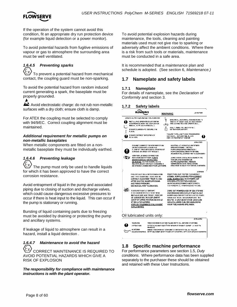
1.7 Nameplate and safety labels 1.7.1 Nameplate For details of nameplate, see the Declaration of Conformity and section 3. 1.7.2 Safety labels
Oil lubricated units only:
1.8 Specific machine performance For performance parameters see section 1.5, Duty conditions. Where performance data has been supplied separately to the purchaser these should be obtained and retained with these User Instructions.
USER INSTRUCTIONS PolyChem M-SERIES ENGLISH 71569218 07-11
flowserve.com Page 9 of 60
®
1.9 Noise level Attention must be given to the exposure of personnel to the noise, and local legislation will define when guidance to personnel on noise limitation is required, and when noise exposure reduction is mandatory. This is typically 80 to 85 dBA.
The usual approach is to control the exposure time to
the noise or to enclose the machine to reduce emitted
sound. You may have already specified a limiting
noise level when the equipment was ordered,
however if no noise requirements were defined, then
attention is drawn to the following table to give an
indication of equipment noise level so that you can
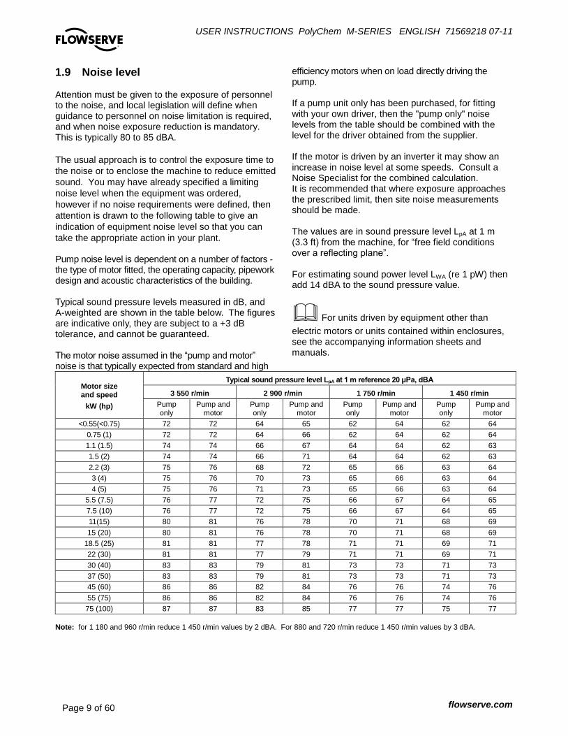
take the appropriate action in your plant. Pump noise level is dependent on a number of factors - the type of motor fitted, the operating capacity, pipework design and acoustic characteristics of the building. Typical sound pressure levels measured in dB, and A-weighted are shown in the table below. The figures are indicative only, they are subject to a +3 dB tolerance, and cannot be guaranteed. The motor noise assumed in the “pump and motor” noise is that typically expected from standard and high
efficiency motors when on load directly driving the pump. If a pump unit only has been purchased, for fitting with your own driver, then the "pump only" noise levels from the table should be combined with the level for the driver obtained from the supplier. If the motor is driven by an inverter it may show an increase in noise level at some speeds. Consult a Noise Specialist for the combined calculation. It is recommended that where exposure approaches the prescribed limit, then site noise measurements should be made. The values are in sound pressure level LpA at 1 m (3.3 ft) from the machine, for “free field conditions over a reflecting plane”. For estimating sound power level LWA (re 1 pW) then add 14 dBA to the sound pressure value.
For units driven by equipment other than
electric motors or units contained within enclosures, see the accompanying information sheets and manuals.
Motor size and speed
kW (hp)
Typical sound pressure level LpA at 1 m reference 20 μPa, dBA
3 550 r/min 2 900 r/min 1 750 r/min 1 450 r/min
Pump only
Pump and motor
Pump only
Pump and motor
Pump only
Pump and motor
Pump only
Pump and motor
<0.55(<0.75) 72 72 64 65 62 64 62 64
0.75 (1) 72 72 64 66 62 64 62 64
1.1 (1.5) 74 74 66 67 64 64 62 63
1.5 (2) 74 74 66 71 64 64 62 63
2.2 (3) 75 76 68 72 65 66 63 64
3 (4) 75 76 70 73 65 66 63 64
4 (5) 75 76 71 73 65 66 63 64
5.5 (7.5) 76 77 72 75 66 67 64 65
7.5 (10) 76 77 72 75 66 67 64 65
11(15) 80 81 76 78 70 71 68 69
15 (20) 80 81 76 78 70 71 68 69
18.5 (25) 81 81 77 78 71 71 69 71
22 (30) 81 81 77 79 71 71 69 71
30 (40) 83 83 79 81 73 73 71 73
37 (50) 83 83 79 81 73 73 71 73
45 (60) 86 86 82 84 76 76 74 76
55 (75) 86 86 82 84 76 76 74 76
75 (100) 87 87 83 85 77 77 75 77
Note: for 1 180 and 960 r/min reduce 1 450 r/min values by 2 dBA. For 880 and 720 r/min reduce 1 450 r/min values by 3 dBA.
USER INSTRUCTIONS PolyChem M-SERIES ENGLISH 71569218 07-11
flowserve.com Page 10 of 60
®
2 TRANSPORT AND STORAGE
2.1 Consignment receipt and unpacking Immediately after receipt of the equipment it must be checked against the delivery/shipping documents for its completeness and that there has been no damage in transportation. Any shortage and/or damage must be reported immediately to Flowserve Pump Division and must be received in writing within ten days of receipt of the equipment. Later claims cannot be accepted. Check any crate, boxes or wrappings for any accessories or spare parts that may be packed separately with the equipment or attached to side walls of the box or equipment. Each product has a unique serial number. Check that this number corresponds with that advised and always quote this number in correspondence as well as when ordering spare parts or further accessories.
2.2 Handling Boxes, crates, pallets or cartons may be unloaded using fork lift vehicles or slings dependent on their size and construction.
2.3 Lifting
A crane must be used for all pump sets in excess of 25 kg (55 lb). Fully trained personnel must carry out lifting, in accordance with local regulations
Pumps and motors often have integral lifting lugs or eye bolts. These are intended for use in only lifting the individual piece of equipment.
Do not use eye bolts or cast-in lifting lugs to lift pump, motor and baseplate assemblies.
To avoid distortion, the pump unit should be lifted as shown.
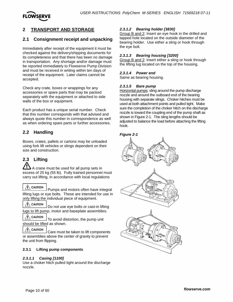
Care must be taken to lift components or assemblies above the center of gravity to prevent the unit from flipping. 2.3.1 Lifting pump components 2.3.1.1 Casing [1100] Use a choker hitch pulled tight around the discharge nozzle.
2.3.1.2 Bearing holder [3830] Group B and 2: Insert an eye hook in the drilled and tapped hole located on the outside diameter of the bearing holder. Use either a sling or hook through the eye bolt. 2.3.1.3 Bearing housing [3200] Group B and 2: insert either a sling or hook through the lifting lug located on the top of the housing. 2.3.1.4 Power end Same as bearing housing. 2.3.1.5 Bare pump Horizontal pumps: sling around the pump discharge nozzle and around the outboard end of the bearing housing with separate slings. Choker hitches must be used at both attachment points and pulled tight. Make sure the completion of the choker hitch on the discharge nozzle is toward the coupling end of the pump shaft as shown in Figure 2-1. The sling lengths should be adjusted to balance the load before attaching the lifting hook. Figure 2-1

USER INSTRUCTIONS PolyChem M-SERIES ENGLISH 71569218 07-11
flowserve.com Page 11 of 60
®
2.3.2 Lifting pump, motor and baseplate assembly
If the baseplate has lifting holes cut in the sides at the end (Type D and Type E bases) insert lifting S hooks at the four corners and use slings or chains to connect to the lifting eye. Do not use slings through the lifting holes. For other baseplates, sling around the pump discharge nozzle, and around the outboard end of the motor frame using choker hitches pulled tight. (Figure 2-1) The sling should be positioned so the weight is not carried through the motor fan housing. Make sure the completion of the choker hitch on the discharge nozzle is toward the coupling end of the pump shaft as shown in Figure 2-1.
2.4 Storage
Store the pump in a clean, dry location away from vibration. Leave flange covers in place to keep dirt and other foreign material out of pump casing. Turn the pump shaft at regular intervals to prevent brinelling of the bearings. The pump may be stored as above for up to 6 months. Consult Flowserve for preservative actions when a longer storage period is needed. 2.4.1 Short term storage and packaging Normal packaging is designed to protect the pump and parts during shipment and for dry, indoor storage for up to six months or less. The following is an overview of our normal packaging:
All loose unmounted items are packaged in a water proof plastic bag and placed under the coupling guard
Inner surfaces of the bearing housing, shaft (area through bearing housing) and bearings are coated with Cortec VCI-329 rust inhibitor, or equal.
Bearing housings are not filled with oil prior to shipment
Regreasable bearings are packed with grease (EXXON POLYREX EM)
Exposed shafts are taped with Polywrap
Flange covers are secured to both the suction and discharge flanges
In some cases with assemblies ordered with external piping, components may be disassembled for shipment
The pump must be stored in a covered, dry location
2.4.2 Long term storage and packaging Long term storage is defined as more than six months, but less than 12 months. The procedure Flowserve follows for long term storage of pumps is given below. These procedures are in addition to the short term procedure.
Each assembly is hermetically (heat) sealed from the atmosphere by means of tack wrap sheeting and rubber bushings (mounting holes)
Desiccant bags are placed inside the tack wrapped packaging
A solid wood box is used to cover the assembly This packaging will provide protection for up to twelve months from humidity, salt laden air, dust etc. After unpacking, protection will be the responsibility of the user. Addition of oil to the bearing housing will remove the inhibitor. If units are to be idle for extended periods after addition of lubricants, inhibitor oils and greases should be used. Every three months, the pump shaft should be rotated approximately 10 revolutions.
2.5 Recycling and end of product life At the end of the service life of the product or its parts, the relevant materials and parts should be recycled or disposed of using an environmentally acceptable method and in accordance with local regulations. If the product contains substances that are harmful to the environment, these should be removed and disposed of in accordance with current local regulations.
Make sure that hazardous substances are disposed of safely and that the correct personal protective equipment is used. The safety specifications must be in accordance with the current local regulations at all times.
USER INSTRUCTIONS PolyChem M-SERIES ENGLISH 71569218 07-11
flowserve.com Page 12 of 60
®
3 DESCRIPTION
3.1 Configurations The PolyChem M-series chemical process pumps are fluoropolymer lined, magnetically coupled, horizontal, end suction, single stage, centrifugal pumps. The ISO version of this pump conforms dimensionally to ISO 2858/5199 while the ANSI model agrees dimensionally with ASME B73.1, both have centerline discharge.
3.2 Nomenclature The pump size will be engraved on the nameplate typically as below: PB 40 – 200 / 190CL (ISO) PJ 2 X 1 - 10 / 8.25CL (ANSI) P = PolyChem pump line A = Magnetic coupling (small) Group A/1 B = Magnetic coupling (medium) Group A/1 C = Magnetic coupling (large) Group A/1 J = Magnetic coupling (small) Group B/2 K = Magnetic coupling (medium) Group B/2 L = Magnetic coupling (large) Group B/2 ISO Pump: “40” = Nominal discharge port size (mm) “200” = Nominal (max.) impeller diameter (mm) “190” =Actual impeller diameter (mm) ANSI Pump: “2” = Nominal suction port size (inch) “1” = Nominal discharge port size (inch) “10” = Nominal (max) impeller diameter (inch) “8.25” – Actual impeller diameter (inch) Impeller style (ISO or ANSI)
CL = closed vane impeller Pump design variations
Long-coupled Close-coupled
Pump groups
References to Group A and Group B relate to ISO pumps, whilst references to Group 1 and Group 2 relate to ANSI pumps
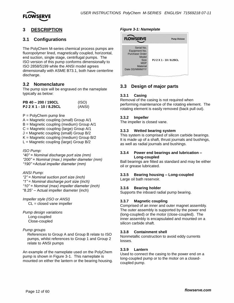
An example of the nameplate used on the PolyChem pump is shown in Figure 3-1. This nameplate is mounted on either the lantern or the bearing housing.
Figure 3-1: Nameplate
3.3 Design of major parts 3.3.1 Casing Removal of the casing is not required when performing maintenance of the rotating element. The rotating element is easily removed (back pull out). 3.3.2 Impeller The impeller is closed vane. 3.3.3 Wetted bearing system This system is comprised of silicon carbide bearings. It is made up of a shaft, thrust journals and bushings, as well as radial journals and bushings. 3.3.4 Power end bearings and lubrication –
Long-coupled Ball bearings are fitted as standard and may be either oil or grease lubricated. 3.3.5 Bearing housing – Long-coupled Large oil bath reservoir. 3.3.6 Bearing holder Supports the inboard radial pump bearing. 3.3.7 Magnetic coupling Comprised of an inner and outer magnet assembly. The outer assembly is supported by the power end (long-coupled) or the motor (close-coupled). The inner assembly is encapsulated and mounted on a silicon carbide shaft. 3.3.8 Containment shell Nonmetallic construction to avoid eddy currents losses. 3.3.9 Lantern Used to connect the casing to the power end on a long-coupled pump or to the motor on a closed-coupled pump.
Serial No. Equipment No.
Purchase Order Model
Size MDP
Material Date DD/MMM/YY
PJ 2 X 1 - 10 / 8.25CL

USER INSTRUCTIONS PolyChem M-SERIES ENGLISH 71569218 07-11
flowserve.com Page 13 of 60
®
3.3.10 Driver The driver is normally an electric motor. Different drive configurations may be fitted such as internal combustion engines, turbines, hydraulic motors etc driving via couplings, belts, gearboxes, drive shafts etc. 3.3.11 Accessories Accessories may be fitted when specified by the customer.
3.4 Performance and operation limits This product has been selected to meet the specification of your purchase order. See section 1.5. The following data is included as additional information to help with your installation. It is typical, and factors such as liquid being pumped, temperature, and material of construction may influence this data. If required, a definitive statement for your application can be obtained from Flowserve. 3.4.1 Material cross reference chart Figure 3-3 is the material cross-reference chart for all PolyChem M-series pumps. 3.4.2 Pressure-temperature ratings PN 16 flanges are standard for the ISO model pump while Class 150 flanges are standard for the ANSI model. Refer to Figure 3-4A and 3-4B for each pump’s pressure-temperature (P-T) rating.
The maximum discharge pressure must be less than or equal to the P-T rating. Discharge pressure may be approximated by adding the suction pressure to the differential pressure developed by the pump. 3.4.3 Suction pressure limits The suction pressure limits for PolyChem M-series pumps is limited by the P-T rating. 3.4.4 Minimum continuous flow The minimum continuous flow (MCF) is based on a percentage of the best efficiency point (BEP). Figure 3-2 identifies the MCF for all PolyChem M-series pumps.
Figure 3-2: Minimum continuous flow
MCF % of BEP
Pump Size 3500/2900 rpm
1750/1450 rpm
1180/960 rpm
P_3x2-6 20% 10% 10%
P_3x2-10 P_50-250 30% 10% 10%
P_4x3-10 P_65-250 N/A 10% 10%
All other sizes 10% 10% 10%

USER INSTRUCTIONS PolyChem M-SERIES ENGLISH 71569218 07-11
flowserve.com Page 14 of 60
®
Figure 3-3: Material cross-reference chart Flowserve
Material Code Designation Durco
Legacy Codes
Equivalent wrought
Designation
EN / ASTM specifications
Nozzle load material group
Z0L48 PFA lined Ductile iron (cast) DIPA None Note 1 1.0
E2025 Ductile Iron Casting 7043 None EN1563, Gr. JS 1025 1.0
E3020 Ductile Iron Casting DCI None A395, Gr. 60-40-18 1.0
A0024 Paper P None N/A
D0005 Carbon Steel SR None N/A
D2044 Quenched and Tempered Steel CK45 None EN 10083-1 N/A
D3013 1018 Carbon Steel Z None N/A
D3058 304 Stainless Steel 304 None A276, Type 304 N/A
D3277 Carbon Steel BB 1144 UNS G11440 N/A
D4035 304, 305, 316, Stainless steel 18-8 None N/A
E2008 Ductile Iron Casting 7040 None EN1563, Gr. JS 1030 N/A
E3006 Cast Iron Casting CI None A48, Gr. 25A N/A
E3007 Cast Iron Casting GG25 None EN1561, Gr. JL 1040 N/A
E3035 Ductile Iron Casting DCI2 None A536, Gr. 65-45-12 N/A
E4034 Ductile Iron Casting DCI4 None Note 2 N/A
I0003 Bronze BZ None N/A
J0018 Reaction bonded silicon carbide SC2 None N/A
J0020 Sintered silicon carbide SC3 None N/A
L0009 Carbon Filled Teflon TFEC None N/A
L1001 Tetrafluoroethylene TFE None N/A
L1010 Ethylene Propylene Rubber EPR None N/A
L1017 Nitrile Butadiene Rubber NBR None N/A
L1103 Polysulphone PS None N/A
M1001 ISO 3506 Grade A2 Class 70 A270 None N/A
M1013 ISO 898/1 Class 8.8 88 None N/A
M3026 Carbon steel SR5 None A449, Type 1 N/A
Z0067 Protective Plated Carbon Steel SRCD None N/A
Z0L50 PFA lined sintered silicon carbide S3PA None N/A
Z0L51 Carbon filled PFA CFPA None N/A
Z0L52 Carbon filled fluoropolymer CFTM None N/A
Z0L54 Fluoropolymer lined fiberglass EFP3 None N/A
Z0L64 Teflon lined A193, Gr. B7 B7TF None N/A
Z0L65 Teflon lined A194, Gr. 2H SRTF None N/A
Z0L72 Teflon – Silicon Rubber – Carbon Steel TSSR None N/A
Z0M22 Viton – Carbon Steel VSR None N/A
Z0M35 PFA lined carbon filled fluoropolymer CFTM None N/A
Z0M36 Fluoropolymer lined NdFeB magnets PFA None N/A
Z0M37 Carbon steel - NdFeB magnets SR None N/A
1. The casting used for ISO pumps is E2025 and for ANSI pumps is E3020 2. Dual Spec. EN1563 Gr. JS1030 & A536 Gr. 65-45-12
Figure 3-4A: Pressure – Temperature Rating ISO Pump with PN 16 Flanges – Material Group No. 1.0 Temperature ˚C -29 -18 38 93 121 149
BAR 16 16 16 16 16 15.5
Temperature ˚F -20 0 100 200 250 300
PSI 232 232 232 232 232 225
Figure 3-4B: Pressure – Temperature Rating ANSI Pump with Class 150 Flanges – Material Group No. 1.0 Temperature ˚C -29 -18 38 93 149
BAR 17.2 17.2 17.2 16.2 14.8
Temperature ˚F -20 0 100 200 300
PSI 250 250 250 235 215
USER INSTRUCTIONS PolyChem M-SERIES ENGLISH 71569218 07-11
flowserve.com Page 15 of 60
®
4 INSTALLATION
4.1 Location The pump should be located to allow room for access, ventilation, maintenance, and inspection with ample headroom for lifting and should be as close as practicable to the supply of liquid to be pumped. Refer to the general arrangement drawing for the pump set.
4.2 Part assemblies The supply of motors and baseplates are optional. As a result, it is the responsibility of the installer to ensure that the motor is assembled to the pump and aligned as detailed in section 4.5 and 4.8.
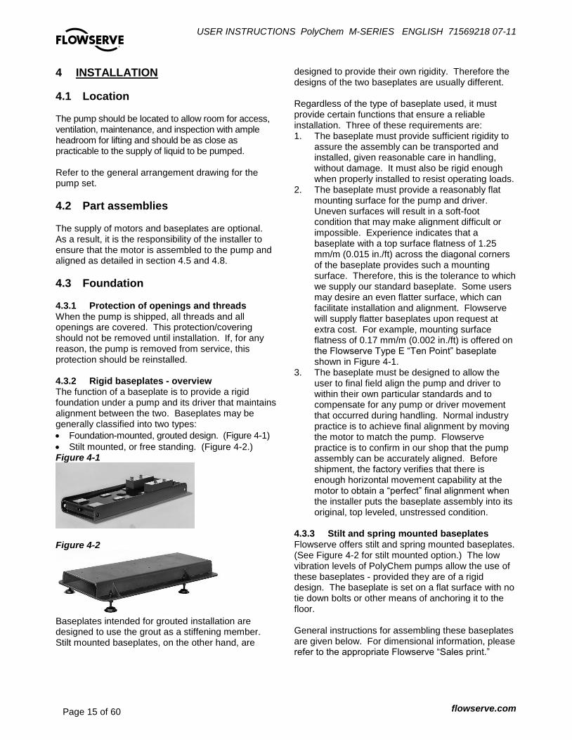
4.3 Foundation 4.3.1 Protection of openings and threads When the pump is shipped, all threads and all openings are covered. This protection/covering should not be removed until installation. If, for any reason, the pump is removed from service, this protection should be reinstalled. 4.3.2 Rigid baseplates - overview The function of a baseplate is to provide a rigid foundation under a pump and its driver that maintains alignment between the two. Baseplates may be generally classified into two types:
Foundation-mounted, grouted design. (Figure 4-1)
Stilt mounted, or free standing. (Figure 4-2.) Figure 4-1
Figure 4-2
Baseplates intended for grouted installation are designed to use the grout as a stiffening member. Stilt mounted baseplates, on the other hand, are
designed to provide their own rigidity. Therefore the designs of the two baseplates are usually different. Regardless of the type of baseplate used, it must provide certain functions that ensure a reliable installation. Three of these requirements are: 1. The baseplate must provide sufficient rigidity to
assure the assembly can be transported and installed, given reasonable care in handling, without damage. It must also be rigid enough when properly installed to resist operating loads.
2. The baseplate must provide a reasonably flat mounting surface for the pump and driver. Uneven surfaces will result in a soft-foot condition that may make alignment difficult or impossible. Experience indicates that a baseplate with a top surface flatness of 1.25 mm/m (0.015 in./ft) across the diagonal corners of the baseplate provides such a mounting surface. Therefore, this is the tolerance to which we supply our standard baseplate. Some users may desire an even flatter surface, which can facilitate installation and alignment. Flowserve will supply flatter baseplates upon request at extra cost. For example, mounting surface flatness of 0.17 mm/m (0.002 in./ft) is offered on the Flowserve Type E “Ten Point” baseplate shown in Figure 4-1.
3. The baseplate must be designed to allow the user to final field align the pump and driver to within their own particular standards and to compensate for any pump or driver movement that occurred during handling. Normal industry practice is to achieve final alignment by moving the motor to match the pump. Flowserve practice is to confirm in our shop that the pump assembly can be accurately aligned. Before shipment, the factory verifies that there is enough horizontal movement capability at the motor to obtain a “perfect” final alignment when the installer puts the baseplate assembly into its original, top leveled, unstressed condition.
4.3.3 Stilt and spring mounted baseplates Flowserve offers stilt and spring mounted baseplates. (See Figure 4-2 for stilt mounted option.) The low vibration levels of PolyChem pumps allow the use of these baseplates - provided they are of a rigid design. The baseplate is set on a flat surface with no tie down bolts or other means of anchoring it to the floor. General instructions for assembling these baseplates are given below. For dimensional information, please refer to the appropriate Flowserve “Sales print.”
USER INSTRUCTIONS PolyChem M-SERIES ENGLISH 71569218 07-11
flowserve.com Page 16 of 60
®
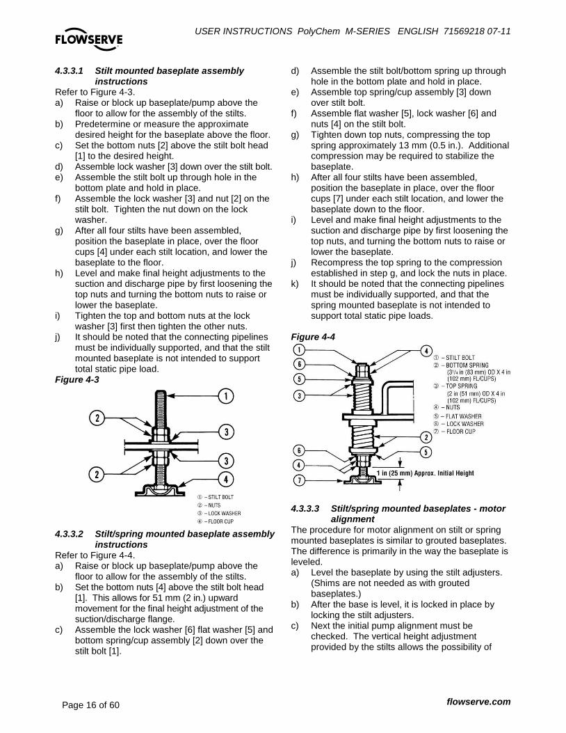
4.3.3.1 Stilt mounted baseplate assembly instructions
Refer to Figure 4-3. a) Raise or block up baseplate/pump above the
floor to allow for the assembly of the stilts. b) Predetermine or measure the approximate
desired height for the baseplate above the floor. c) Set the bottom nuts [2] above the stilt bolt head
[1] to the desired height. d) Assemble lock washer [3] down over the stilt bolt. e) Assemble the stilt bolt up through hole in the
bottom plate and hold in place. f) Assemble the lock washer [3] and nut [2] on the
stilt bolt. Tighten the nut down on the lock washer.
g) After all four stilts have been assembled, position the baseplate in place, over the floor cups [4] under each stilt location, and lower the baseplate to the floor.
h) Level and make final height adjustments to the suction and discharge pipe by first loosening the top nuts and turning the bottom nuts to raise or lower the baseplate.
i) Tighten the top and bottom nuts at the lock washer [3] first then tighten the other nuts.
j) It should be noted that the connecting pipelines must be individually supported, and that the stilt mounted baseplate is not intended to support total static pipe load.
Figure 4-3
4.3.3.2 Stilt/spring mounted baseplate assembly
instructions Refer to Figure 4-4. a) Raise or block up baseplate/pump above the
floor to allow for the assembly of the stilts. b) Set the bottom nuts [4] above the stilt bolt head
[1]. This allows for 51 mm (2 in.) upward movement for the final height adjustment of the suction/discharge flange.
c) Assemble the lock washer [6] flat washer [5] and bottom spring/cup assembly [2] down over the stilt bolt [1].
d) Assemble the stilt bolt/bottom spring up through hole in the bottom plate and hold in place.
e) Assemble top spring/cup assembly [3] down over stilt bolt.
f) Assemble flat washer [5], lock washer [6] and nuts [4] on the stilt bolt.
g) Tighten down top nuts, compressing the top spring approximately 13 mm (0.5 in.). Additional compression may be required to stabilize the baseplate.
h) After all four stilts have been assembled, position the baseplate in place, over the floor cups [7] under each stilt location, and lower the baseplate down to the floor.
i) Level and make final height adjustments to the suction and discharge pipe by first loosening the top nuts, and turning the bottom nuts to raise or lower the baseplate.
j) Recompress the top spring to the compression established in step g, and lock the nuts in place.
k) It should be noted that the connecting pipelines must be individually supported, and that the spring mounted baseplate is not intended to support total static pipe loads.
Figure 4-4
4.3.3.3 Stilt/spring mounted baseplates - motor
alignment The procedure for motor alignment on stilt or spring mounted baseplates is similar to grouted baseplates. The difference is primarily in the way the baseplate is leveled. a) Level the baseplate by using the stilt adjusters.
(Shims are not needed as with grouted baseplates.)
b) After the base is level, it is locked in place by locking the stilt adjusters.
c) Next the initial pump alignment must be checked. The vertical height adjustment provided by the stilts allows the possibility of

USER INSTRUCTIONS PolyChem M-SERIES ENGLISH 71569218 07-11
flowserve.com Page 17 of 60
®
slightly twisting the baseplate. If there has been no transit damage or twisting of the baseplate during stilt height adjustment, the pump and driver should be within 0.38 mm (0.015 in.) parallel, and 0.0025 mm/mm (0.0025 in./in.) angular alignment. If this is not the case, check to see if the driver mounting fasteners are centered in the driver feet holes.
d) If the fasteners are not centered there was likely shipping damage. Re-center the fasteners and perform a preliminary alignment to the above tolerances by shimming under the motor for vertical alignment, and by moving the pump for horizontal alignment.
e) If the fasteners are centered, then the baseplate may be twisted. Slightly adjust (one turn of the adjusting nut) the stilts at the driver end of the baseplate and check for alignment to the above tolerances. Repeat as necessary while maintaining a level condition as measured from the pump discharge flange.
f) Lock the stilt adjusters. The remaining steps are as listed for new grouted baseplates.
4.4 Grouting a) The pump foundation should be located as close
to the source of the fluid to be pumped as practical.
b) There should be adequate space for workers to install, operate, and maintain the pump. The foundation should be sufficient to absorb any vibration and should provide a rigid support for the pump and motor.
c) Recommended mass of a concrete foundation should be three times that of the pump, motor and base. Refer to Figure 4-5.
Foundation bolts are imbedded in the concrete inside a sleeve to allow some movement of the bolt. Figure 4-5
d) Level the pump baseplate assembly. If the baseplate has machined coplanar mounting surfaces, these machined surfaces are to be referenced when leveling the baseplate. This may require that the pump and motor be removed from the baseplate in order to reference the machined faces. If the baseplate is without machined coplanar mounting surfaces, the pump and motor are to be left on the baseplate. The proper surfaces to reference when leveling the pump baseplate assembly are the pump suction and discharge flanges. DO NOT stress the baseplate.
e) Do not bolt the suction or discharge flanges of the pump to the piping until the baseplate foundation is completely installed. If equipped, use leveling jackscrews to level the baseplate. If jackscrews are not provided, shims and wedges should be used. (See Figure 4-5.) Check for levelness in both the longitudinal and lateral directions. Shims should be placed at all base anchor bolt locations, and in the middle edge of the base if the base is more than 1.5 m (5 ft.) long. Do not rely on the bottom of the baseplate to be flat. Standard baseplate bottoms are not machined, and it is not likely that the field mounting surface is flat.
f) After leveling the baseplate, tighten the anchor bolts. If shims were used, make sure that the baseplate was shimmed near each anchor bolt before tightening. Failure to do this may result in a twist of the baseplate, which could make it impossible to obtain final alignment.
g) Check the level of the baseplate to make sure that tightening the anchor bolts did not disturb the level of the baseplate. If the anchor bolts did change the level, adjust the jackscrews or shims as needed to level the baseplate.
h) Continue adjusting the jackscrews or shims and tightening the anchor bolts until the baseplate is level.
i) Check initial alignment. If the pump and motor were removed from the baseplate proceed with step j) first, then the pump and motor should be reinstalled onto the baseplate using Flowserve’s factory preliminary alignment procedure as described in section 4.5, and then continue with the following. As described above, pumps are given a preliminary alignment at the factory. This preliminary alignment is done in a way that ensures that, if the installer duplicates the factory conditions, there will be sufficient clearance between the motor hold down bolts and motor foot holes to move the motor into final alignment. If the pump and motor were properly reinstalled to the baseplate or if they were not removed from the
USER INSTRUCTIONS PolyChem M-SERIES ENGLISH 71569218 07-11
flowserve.com Page 18 of 60
®
baseplate and there has been no transit damage, and also if the above steps where done properly, the pump and driver should be within 0.38 mm (0.015 in.) FIM (Full Indicator Movement) parallel, and 0.0025 mm/mm (0.0025 in./in.) FIM angular. If this is not the case, first check to see if the driver mounting fasteners are centered in the driver feet holes. If not, re-center the fasteners and perform a preliminary alignment to the above tolerances by shimming under the motor for vertical alignment, and by moving the pump for horizontal alignment.
j) Grout the baseplate. A non-shrinking grout should be used. Make sure that the grout fills the area under the baseplate. After the grout has cured, check for voids and repair them. Jackscrews, shims and wedges should be removed from under the baseplate at this time. If they were to be left in place, they could rust, swell, and cause distortion in the baseplate.
k) Run piping to the suction and discharge of the pump. There should be no piping loads transmitted to the pump after connection is made. Recheck the alignment to verify that there are no significant loads.
4.5 Initial alignment – Long-coupled 4.5.1 Horizontal initial alignment procedure The purpose of factory alignment is to ensure that the user will have full utilization of the clearance in the motor holes for final job-site alignment. To achieve this, the factory alignment procedure specifies that the pump be aligned in the horizontal plane to the motor, with the motor foot bolts centered in the motor holes. This procedure ensures that there is sufficient clearance in the motor holes for the customer to field align the motor to the pump, to zero tolerance. This philosophy requires that the customer be able to place the base in the same condition as the factory. Thus the factory alignment will be done with the base sitting in an unrestrained condition on a flat and level surface. This standard also emphasizes the need to ensure the shaft spacing is adequate to accept the specified coupling spacer. The factory alignment procedure is summarized below: a) The baseplate is placed on a flat and level
workbench in a free and unstressed position. b) The baseplate is leveled as necessary. Leveling
is accomplished by placing shims under the rails of the base at the appropriate anchor bolt hole locations. Levelness is checked in both the longitudinal and lateral directions.
c) The motor and appropriate motor mounting hardware is placed on the baseplate and the motor is checked for any planar soft-foot condition. If any is present it is eliminated by shimming.
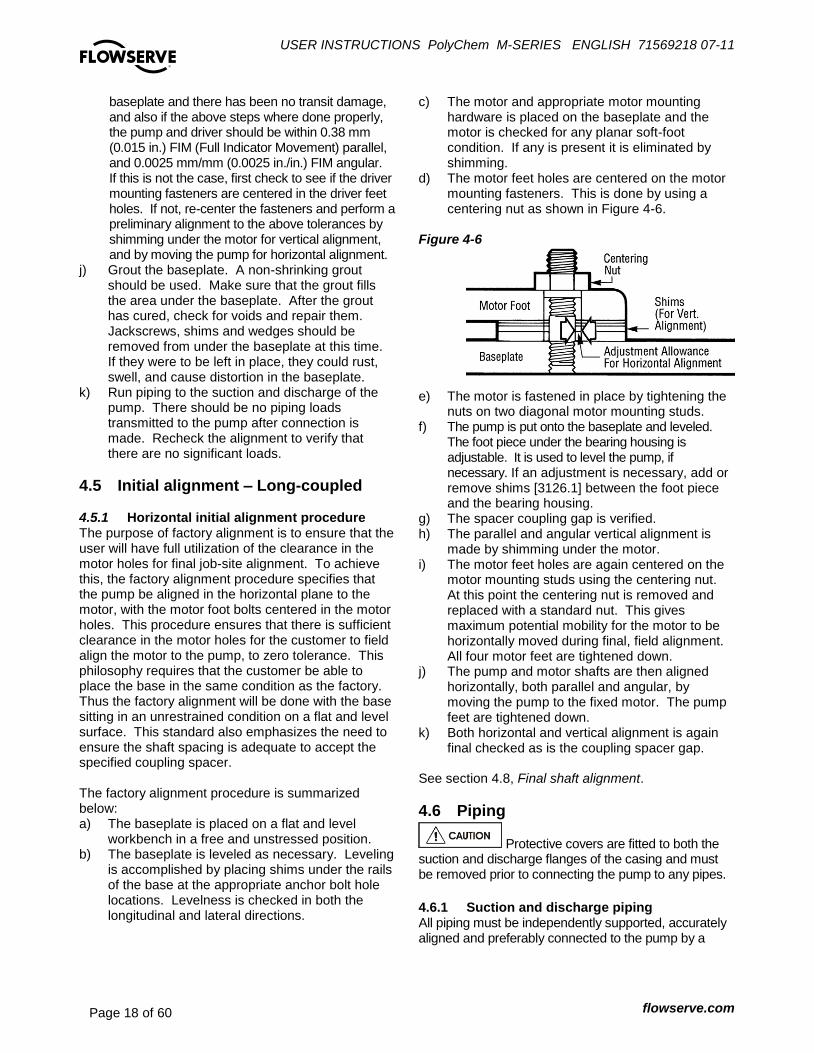
d) The motor feet holes are centered on the motor mounting fasteners. This is done by using a centering nut as shown in Figure 4-6.
Figure 4-6
e) The motor is fastened in place by tightening the nuts on two diagonal motor mounting studs.
f) The pump is put onto the baseplate and leveled. The foot piece under the bearing housing is adjustable. It is used to level the pump, if necessary. If an adjustment is necessary, add or remove shims [3126.1] between the foot piece and the bearing housing.
g) The spacer coupling gap is verified. h) The parallel and angular vertical alignment is
made by shimming under the motor. i) The motor feet holes are again centered on the
motor mounting studs using the centering nut. At this point the centering nut is removed and replaced with a standard nut. This gives maximum potential mobility for the motor to be horizontally moved during final, field alignment. All four motor feet are tightened down.
j) The pump and motor shafts are then aligned horizontally, both parallel and angular, by moving the pump to the fixed motor. The pump feet are tightened down.
k) Both horizontal and vertical alignment is again final checked as is the coupling spacer gap.
See section 4.8, Final shaft alignment.
4.6 Piping
Protective covers are fitted to both the suction and discharge flanges of the casing and must be removed prior to connecting the pump to any pipes.
4.6.1 Suction and discharge piping All piping must be independently supported, accurately aligned and preferably connected to the pump by a

USER INSTRUCTIONS PolyChem M-SERIES ENGLISH 71569218 07-11
flowserve.com Page 19 of 60
®
short length of flexible piping. The pump should not have to support the weight of the pipe or compensate for misalignment. It should be possible to install suction and discharge bolts through mating flanges without pulling or prying either of the flanges. All piping must be tight. Pumps may air-bind if air is allowed to leak into the piping. If the pump flange(s) have tapped holes, select flange fasteners with thread engagement at least equal to the fastener diameter but that do not bottom out in the tapped holes before the joint is tight. The following is the recommended procedure for attaching piping to the PolyChem M-series pump (see section 6.5 for torque values)
Check the surface of both flanges (pump/pipe) to ensure they are clean, flat, and without defects
Lubricate the fasteners
Hand tighten all of the fasteners in a crisscross pattern
The fasteners should be torqued in increments – based a crisscross pattern
o The first increment should be at 75% of the full torque
o The second increment should be at the full torque
o Verify that the torque value of the 1st
fastener is still at the full torque value
Retorque all fasteners after 24 hours or after the first thermal cycle
Retorque all fasteners at least annually
4.6.2 Suction piping To avoid NPSH and suction problems, suction piping must be at least as large as the pump suction connection. Never use pipe or fittings on the suction that are smaller in diameter than the pump suction size. Figure 4-7 illustrates the ideal piping configuration with a minimum of 10 pipe diameters between the source and the pump suction. In most cases, horizontal reducers should be eccentric and mounted with the flat side up as shown in Figure 4-8 with a maximum of one pipe size reduction. Never mount eccentric reducers with the flat side down. Horizontally mounted concentric reducers should not be used if there is any possibility of entrained air in the process fluid. Vertically mounted concentric reducers are acceptable. In applications where the fluid is completely de-aerated and free of any vapor or suspended solids, concentric reducers are preferable to eccentric reducers.
Figure 4-7 Figure 4-8
Avoid the use of throttling valves and strainers in the suction line. Start up strainers must be removed shortly before start up. When the pump is installed below the source of supply, a valve should be installed in the suction line to isolate the pump and permit pump inspection and maintenance. However, never place a valve directly on the suction nozzle of the pump. Refer to the Durco Pump Engineering Manual and the Centrifugal Pump IOM Section of the Hydraulic Institute Standards for additional recommendations on suction piping. (See section 10.) Refer to section 3.4 for performance and operating limits. 4.6.3 Discharge piping Install a valve in the discharge line. This valve is required for regulating flow and/or to isolate the pump for inspection and maintenance.
When fluid velocity in the pipe is high, for example, 3 m/s (10 ft/sec) or higher, a rapidly closing discharge valve can cause a damaging pressure surge. A dampening arrangement should be provided in the piping. 4.6.4 ALLOWABLE NOZZLE LOADS Introduction
Never use the pump as a support for piping. Maximum Forces and moments allowed on pump flanges vary based on the pump size. When these forces and moments are minimized, there is a corresponding reduction in misalignment, hot bearings, worn couplings, vibration and possible failure of the pump casing. The following points should be strictly followed:
Prevent excessive external pipe load
Never draw piping into place by applying force to pump flange connections
Do not mount expansion joints so that their force, due to internal pressure, acts on the pipe flange

USER INSTRUCTIONS PolyChem M-SERIES ENGLISH 71569218 07-11
flowserve.com Page 20 of 60
®
The PolyChem product line is designed to meet the requirements of ISO 5199 and ANSI/HI 9.6.2. Allowable nozzle loads for ISO pumps may be calculated using ISO 5199 or ANSI/HI 9.6.2 by selecting a comparable pump size. Figure 4-9: Casing Material Correction Factors – Material Group No. 1.0
Temp. ˚C -29 38 93 150
Temp. ˚F -20 100 200 300
Correction Factors 0.89 0.89 0.83 0.78
Figure 4-10: Baseplate Correction Factors
Base Type Grouted Bolted Stilt
Mounted
Type A 1.0 0.7 0.65
Type B - Polybase 1.0 N/A 0.95
Type C N/A 1.0 1.0
Type D 1.0 0.8 0.75
Type E - PIP 1.0 0.95 N/A
Polyshield - Baseplate / Foundation 1.0 N/A N/A
4.6.4.1 PolyChem M-series Pumps The following steps are based upon ANSI/HI 9.6.2. All information necessary to complete the evaluation is given below. For complete details please review the standard. a) PolyChem M-series pumps are only
manufactured from Ductile Iron. For reference the “Material Group No.” for this material is 1.0
b) Find the “Casing Material Correction Factor” in Figure 4-9 based upon the operating temperature. Interpolation may be used to determine the correction factor for a specific temperature.
c) Find the “Baseplate Correction Factor” in Figure 4-10. The correction factor depends upon how the baseplate is to be installed
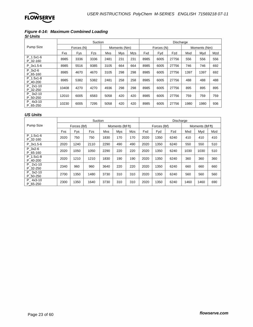
d) Locate the pump model being evaluated in Figure 4-14 and multiply each load rating by the casing correction factor. Record the adjusted Figure 4-14 loads.
e) Locate the pump model being evaluated in Figures 4-15 and 4-16 and multiply each load rating by the baseplate correction factor. Record the adjusted Figure 4-15 and 4-16 loads.
f) Compare the adjusted Figure 4-14 values (Step D) to the values shown in Figure 4-13. The lower of these two values should be used as the
adjusted Figure 4-13 values. (The HI standard also asks that Figure 4-13 loads be reduced if Figure 4-15 or 4-16 values are lower. Flowserve does not follow this step.)
Figure 4-11: Coordinate System
g) Calculate the applied loads at the casing flanges
according to the coordinate system found in Figure 4-11. The 12 forces and moments possible are Fxs, Fys, Fzs, Mxs, Mys, Mzs, Fxd, Fyd, Fzd, Mxd, Myd and Mzd. For example, Fxd designates Force in the “x” direction on the discharge flange. Mys designates the Moment about the “y”-axis on the suction flange.
h) Figure 4-12 gives the acceptance criteria equations. For long-coupled pumps, equation sets 1 through 5 must be satisfied. For close coupled pumps only equation sets 1 and 2 must be satisfied.
i) Equation set 1: Each applied load is divided by the corresponding adjusted Figure 4-13 value. The absolute value of each ratio must be less than or equal to one.
j) Equation set 2: The summation of the absolute values of each ratio must be less than or equal to two. The ratios are the applied load divided by the adjusted Figure 4-14 values.
k) Equation sets 3 and 4: These equations are checking for coupling misalignment due to nozzle loading in each axis. Each applied load is divided by the corresponding adjusted load from Figure 4-15 and 4-16. The result of each equation must be between one and negative one.
l) Equation set 5: This equation calculates the total shaft movement from the results of equations 3 and 4. The result must be less than or equal to one.

USER INSTRUCTIONS PolyChem M-SERIES ENGLISH 71569218 07-11
flowserve.com Page 21 of 60
®
Figure 4-12: Acceptance Criteria Equations Set Equations Figure Remarks
1
0.1,0.1,0.1,0.1,0.1,0.1
,0.1,0.1,0.1,0.1,0.1,0.1
______
______
adjzd
zd
adjyd
yd
adjxd
xd
adjzd
zd
adjyd
yd
adjxd
xd
adjzs
zs
adjys
ys
adjxs
xs
adjzs
zs
adjys
ys
adjxs
xs
M
M
M
M
M
M
F
F
F
F
F
F
M
M
M
M
M
M
F
F
F
F
F
F
Adjusted 4-13
Maximum individual loading
2
0.2______
______
adjzd
zd
adjyd
yd
adjxd
xd
adjzd
zd
adjyd
yd
adjxd
xd
adjzs
zs
adjys
ys
adjxs
xs
adjzs
zs
adjys
ys
adjxs
xs
M
M
M
M
M
M
F
F
F
F
F
F
M
M
M
M
M
M
F
F
F
F
F
F
Adjusted
4-14
Nozzle stress, bolt
stress, pump
slippage
3
_ _ _ _
_ _ _ _
ys ysxs zs
ys adj xs adj ys adj zs adj
yd ydxd zd
yd adj xd adj yd adj zd adj
F MM MA
F M M M
F MM M
F M M M
0.10.1 A
Adjusted 4-15
y-axis movement
4
_ _ _ _ _
_ _ _ _ _ _
ysxs zs xs zs
xs adj zs adj xs adj ys adj zs adj
yd ydxd zd xd zd
xd adj yd adj zd adj xd adj yd adj zd adj
MF F M MB
F F M M M
F MF F M M
F F F M M M
0.10.1 B
Adjusted 4-16
z-axis movement
5 0.122 BA - Combined
axis movement
Note: All of the above equations are found by dividing the applied piping loads by the adjusted figure values.

USER INSTRUCTIONS PolyChem M-SERIES ENGLISH 71569218 07-11
flowserve.com Page 22 of 60
®
Figure 4-13: Maximum Individual Loading SI Units
Pump Size
Suction Discharge
Forces (N) Moments (Nm) Forces (N) Moments (Nm)
Fxs Fys Fzs Mxs Mys Mzs Fxd Fyd Fzd Mxd Myd Mzd
P_1.5x1-6 P_32-160
4670 3336 3336 976 231 231 3558 6005 13344 556 556 556
P_3x1.5-6 4670 5516 5560 1220 664 664 3558 6005 13344 678 746 692
P_3x2-6 P_65-160
4670 4670 4670 1220 298 298 3558 6005 13344 678 1356 692
P_1.5x1-8 P_40-200
4670 5382 5382 976 258 258 3558 6005 13344 488 488 488
P_ 2x1-10 P_32-250
10408 4270 4270 1722 298 298 6227 6005 14456 895 895 895
P_ 3x2-10 P_50-250
12010 6005 6583 1763 420 420 6227 6005 14456 759 759 759
P_ 4x3-10 P_65-250
10230 6005 6672 1763 420 420 6227 6005 14456 1627 1980 936
US Units
Pump Size
Suction Discharge
Forces (lbf) Moments (lbf∙ft) Forces (lbf) Moments (lbf∙ft)
Fxs Fys Fzs Mxs Mys Mzs Fxd Fyd Fzd Mxd Myd Mzd
P_1.5x1-6 P_32-160
1050 750 750 720 170 170 800 1350 3000 410 410 410
P_3x1.5-6 1050 1240 1250 900 490 490 800 1350 3000 500 550 510
P_3x2-6 P_65-160
1050 1050 1050 900 220 220 800 1350 3000 500 1000 510
P_1.5x1-8 P_40-200
1050 1210 1210 720 190 190 800 1350 3000 360 360 360
P_ 2x1-10 P_32-250
2340 960 960 1270 220 220 1400 1350 3250 660 660 660
P_ 3x2-10 P_50-250
2700 1350 1480 1300 310 310 1400 1350 3250 560 560 560
P_ 4x3-10 P_65-250
2300 1350 1500 1300 310 310 1400 1350 3250 1200 1460 690
USER INSTRUCTIONS PolyChem M-SERIES ENGLISH 71569218 07-11
flowserve.com Page 23 of 60
®
Figure 4-14: Maximum Combined Loading SI Units
Pump Size
Suction Discharge
Forces (N) Moments (Nm) Forces (N) Moments (Nm)
Fxs Fys Fzs Mxs Mys Mzs Fxd Fyd Fzd Mxd Myd Mzd
P_1.5x1-6 P_32-160
8985 3336 3336 2481 231 231 8985 6005 27756 556 556 556
P_3x1.5-6 8985 5516 9385 3105 664 664 8985 6005 27756 746 746 692
P_3x2-6 P_65-160
8985 4670 4670 3105 298 298 8985 6005 27756 1397 1397 692
P_1.5x1-8 P_40-200
8985 5382 5382 2481 258 258 8985 6005 27756 488 488 488
P_ 2x1-10 P_32-250
10408 4270 4270 4936 298 298 8985 6005 27756 895 895 895
P_ 3x2-10 P_50-250
12010 6005 6583 5058 420 420 8985 6005 27756 759 759 759
P_ 4x3-10 P_65-250
10230 6005 7295 5058 420 420 8985 6005 27756 1980 1980 936
US Units
Pump Size
Suction Discharge
Forces (lbf) Moments (lbf∙ft) Forces (lbf) Moments (lbf∙ft)
Fxs Fys Fzs Mxs Mys Mzs Fxd Fyd Fzd Mxd Myd Mzd
P_1.5x1-6 P_32-160
2020 750 750 1830 170 170 2020 1350 6240 410 410 410
P_3x1.5-6 2020 1240 2110 2290 490 490 2020 1350 6240 550 550 510
P_3x2-6 P_65-160
2020 1050 1050 2290 220 220 2020 1350 6240 1030 1030 510
P_1.5x1-8 P_40-200
2020 1210 1210 1830 190 190 2020 1350 6240 360 360 360
P_ 2x1-10 P_32-250
2340 960 960 3640 220 220 2020 1350 6240 660 660 660
P_ 3x2-10 P_50-250
2700 1350 1480 3730 310 310 2020 1350 6240 560 560 560
P_ 4x3-10 P_65-250
2300 1350 1640 3730 310 310 2020 1350 6240 1460 1460 690

USER INSTRUCTIONS PolyChem M-SERIES ENGLISH 71569218 07-11
flowserve.com Page 24 of 60
®
Figure 4-15: Maximum Y-Axis Loading for Shaft Deflection SI Units
Pump Size
Suction Discharge
Forces (N) Moments (Nm) Forces (N) Moments (Nm)
Fxs Fys Fzs Mxs Mys Mzs Fxd Fyd Fzd Mxd Myd Mzd
Group 1 & A -8896 1220.4 1627.2 1695 6672 -678 2034 1695
Group 2 & B -15568 1762.8 1762.8 4068 11120 -1627 2034 4068
US Units
Pump Size
Suction Discharge
Forces (lbf) Moments (lbf∙ft) Forces (lbf) Moments (lbf∙ft)
Fxs Fys Fzs Mxs Mys Mzs Fxd Fyd Fzd Mxd Myd Mzd
Group 1 & A -2000 900 1200 1250 1500 -500 1500 1250
Group 2 & B -3500 1300 1300 3000 2500 -1200 1500 3000
Figure 4-16: Maximum Z-Axis Loading for Shaft Deflection SI Units
Pump Size
Suction Discharge
Forces (N) Moments (Nm) Forces (N) Moments (Nm)
Fxs Fys Fzs Mxs Mys Mzs Fxd Fyd Fzd Mxd Myd Mzd
Group 1 & A 4670 -5560 2034 1627 -3390 3558 8896 -13344 -2034 1356 -3390
Group 2 & B 15568 -6672 2034 1763 -4746 6227 11120 -14456 -2034 2915 -4746
US Units
Pump Size
Suction Discharge
Forces (lbf) Moments (lbf∙ft) Forces (lbf) Moments (lbf∙ft)
Fxs Fys Fzs Mxs Mys Mzs Fxd Fyd Fzd Mxd Myd Mzd
Group 1 & A 1050 -1250 1500 1200 -2500 800 2000 -3000 -1500 1000 -2500
Group 2 & B 3500 -1500 1500 1300 -3500 1400 2500 -3250 -1500 2150 -3500
4.6.5 Pump and shaft alignment check – Long-
coupled After connecting the piping, rotate the pump drive shaft clockwise (viewed from motor end) by hand several complete revolutions to be sure there is no binding and that all parts are free. Recheck shaft alignment (see section 4.5). If piping caused unit to be out of alignment, correct piping to relieve strain on the pump. 4.6.6 Auxiliary piping 4.6.6.1 Piping connection - Oil mist lubrication
system The piping connections for an oil mist lubrication system are shown below.
Figure 4-17 Oil Mist Connections – Labyrinth Style Oil Seals (Standard)
USER INSTRUCTIONS PolyChem M-SERIES ENGLISH 71569218 07-11
flowserve.com Page 25 of 60
®
4.7 Electrical connections
Electrical connections must be made by a qualified Electrician in accordance with relevant local national and international regulations.
It is important to be aware of the EUROPEAN DIRECTIVE on potentially explosive areas where compliance with IEC60079-14 is an additional requirement for making electrical connections.
It is important to be aware of the EUROPEAN DIRECTIVE on electromagnetic compatibility when wiring up and installing equipment on site. Attention must be paid to ensure that the techniques used during wiring/installation do not increase electromagnetic emissions or decrease the electromagnetic immunity of the equipment, wiring or any connected devices. If in any doubt contact Flowserve for advice.
The motor must be wired up in accordance with the motor manufacturer's instructions (normally supplied within the terminal box) including any temperature, earth leakage, current and other protective devices as appropriate. The identification nameplate should be checked to ensure the power supply is appropriate.
See section 5.3, Direction of rotation before connecting the motor to the electrical supply.
4.8 Final shaft alignment check – Long-coupled
a) Level baseplate if appropriate. b) Mount and level pump if appropriate. Level the
pump by putting a level on the discharge flange. If not level, adjust the footpiece by adding or removing shims [3126.1] between the footpiece and the bearing housing.
c) Check initial alignment. If pump and driver have been remounted or the specifications given below are not met, perform an initial alignment as described in section 4.5. This ensures there will be sufficient clearance between the motor hold down bolts and motor foot holes to move the motor into final alignment. The pump and driver should be within 0.38 mm (0.015 in.) FIM (full indicator movement) parallel, and 0.0025 mm/mm (0.0025 in./in.) FIM angular.
Stilt mounted baseplates If initial alignment cannot be achieved with the motor fasteners centered, the baseplate may be twisted. Slightly adjust (one turn of the adjusting nut) the stilts at the driver end of the baseplate and check for alignment to the above tolerances. Repeat as necessary while maintaining a level condition as measured from the pump discharge flange.
d) Run piping to the suction and discharge to the pump. There should be no piping loads transmitted to the pump after connection is made. Recheck the alignment to verify that there are no significant changes.
e) Perform final alignment. Check for soft-foot under the driver. An indicator placed on the coupling, reading in the vertical direction, should not indicate more than 0.05 mm (0.002 in.) movement when any driver fastener is loosened. Align the driver first in the vertical direction by shimming underneath its feet.
f) When satisfactory alignment is obtained the number of shims in the pack should be minimized. It is recommended that no more than five shims be used under any foot. Final horizontal alignment is made by moving the driver. Maximum pump reliability is obtained by having near perfect alignment. Flowserve recommends no more than 0.05 mm (0.002 in.) parallel, and 0.0005 mm/mm (0.0005 in./in.) angular misalignment. (See section 6.8.4.1)
g) Operate the pump for at least an hour or until it reaches final operating temperature. Shut the pump down and recheck alignment while the pump is hot. Piping thermal expansion may change the alignment. Realign pump as necessary.
4.9 Protection systems
The following protection systems are recommended particularly if the pump is installed in a potentially explosive area or is handling a hazardous liquid. If in doubt consult Flowserve. If there is any possibility of the system allowing the pump to run against a closed valve or below minimum continuous safe flow a protection device should be installed to ensure the temperature of the liquid does not rise to an unsafe level. If there are any circumstances in which the system can allow the pump to run dry, or start up empty, a power monitor should be fitted to stop the pump or prevent it from being started. This is particularly
USER INSTRUCTIONS PolyChem M-SERIES ENGLISH 71569218 07-11
flowserve.com Page 26 of 60
®
relevant if the pump is handling a flammable liquid. If leakage of product from the pump can cause a hazard it is recommended that an appropriate leakage detection system is installed. To prevent excessive surface temperatures at bearings it is recommended that temperature or vibration monitoring is carried out.
5 COMMISSIONING, STARTUP, OPERATION AND SHUTDOWN
These operations must be carried out by fully qualified personnel.
NEVER RUN THE PUMP DRY OR WITHOUT PROPER PRIME (Pump flooded). Operating the pump dry may cause immediate damage to the bearings, magnets, etc..
5.1 Pre-commissioning procedure 5.1.1 Pre start-up checks Prior to starting the pump it is essential that the following checks be made. These checks are all described in detail in the Maintenance section of this manual.
Pump and motor properly secured to the baseplate
All fasteners tightened to the correct torque
Coupling guard in place and not rubbing
Rotation check, see section 5.3. This is absolutely essential
Bearing lubrication
Pump instrumentation is operational
Pump is primed
Rotation of shaft by hand As a final step in preparation for operation, it is important to rotate the shaft by hand to be certain that all rotating parts move freely, and that there are no foreign objects in the pump casing.
5.2 Pump lubricants 5.2.1 Oil bath The standard bearing housing bearings are oil bath lubricated and are not lubricated by Flowserve. Before operating the pump, fill the bearing housing to the center of the oil sight glass with the proper type oil. (See Figure 5-1 for approximate amount of oil required - do not overfill.)
The oil level in the bearing housing must be maintained at ±3 mm (±
1/8 in.) from the center of the
sight glass. The sight glass has a 6 mm (¼ in.) hole in the center of its reflector. The bearing housing oil level must be within the circumference of the center hole to ensure adequate lubrication of the bearings. See Figure 5-2 for a general description of the lubricants to be used and Figure 5-6 for recommended lubricants. DO NOT USE DETERGENT OILS. The oil must be free of water, sediment, resin, soaps, acid and fillers of any kind. It should contain rust and oxidation inhibitors. The proper oil viscosity is determined by the bearing housing operating temperature as given in Figure 5-3. To add oil to the housing, clean and then remove the vent plug [6569.2] at the top of the bearing housing, pour in oil until it is visually half way up in the sight glass [3855]. Fill the constant level oiler bottle, if used, and return it to its position. The correct oil level is obtained with the constant level oiler in its lowest position, which results in the oil level being at the top of the oil inlet pipe nipple, or half way up in the sight glass window. Oil must be visible in the bottle at all times. In many pumping applications lubricating oil becomes contaminated before it loses its lubricating qualities or breaks down. For this reason it is recommended that the first oil change take place after approximately 160 hours of operation, at which time, the used oil should be examined carefully for contaminants. During the initial operating period monitor the bearing housing operating temperature. Record the external bearing housing temperature. See Figure 5-4 for maximum acceptable temperatures. The normal oil change interval is based on temperature and is shown in Figure 5-5. Figure 5-1: Amount of oil required
Pump PolyChem M-series
Group A 458 ml (15.5 fl. oz.)
Group 1 251 ml (8.5 fl. oz.)
Group B 946 ml (32 fl. oz.)
Group 2 946 ml (32 fl. oz.)
Figure 5-2: Lubricant description
Mineral oil
Quality mineral oil with rust and oxidation inhibitors.
Synthetic Royal Purple or Conoco SYNCON (or equivalent). Some synthetic lubricants require Viton O-rings.
Grease EXXON POLYREX EM (or compatible)

USER INSTRUCTIONS PolyChem M-SERIES ENGLISH 71569218 07-11
flowserve.com Page 27 of 60
®
Figure 5-3: Oil viscosity grades
Maximum oil temperature
ISO viscosity grade
Minimum viscosity index
Up to 71 °C (160 °F) 46 95
71-80 °C (160-175 °F) 68 95
80-94 °C (175-200 °F) 100 95
Figure 5-4: Maximum external housing temperatures
Lubrication Temperature
Oil bath 82 °C (180 °F)
Oil mist 82 °C (180 °F)
Grease 94 °C (200 °F)
The maximum temperature that the bearing can be exposed to is 105 °C (220 °F). Bearing temperatures may be up to 16 °C (30 °F) higher than the housing temperature. Figure 5-5: Lubrication intervals*
Lubricant Under 71 °C (160 °F)
71-80 °C (160-175 °F)
80-94 °C (175-200 °F)
Mineral oil 6 months 3 months 1.5 months
Synthetic oil 18 months 18 months 18 months
* Assuming good maintenance and operation practices, and no contamination.
5.2.2 Grease
Do not fill the housing with oil when greased bearings are used. The oil will leach the grease out of the bearings and the life of the bearings may be drastically reduced. 5.2.2.1 Grease for life Double shielded or double sealed bearings These bearings are packed with grease by the bearing manufacturer and should not be relubricated. The replacement interval for these bearings is greatly affected by their operating temperature and speed. Shielded bearings typically operate cooler. 5.2.3 Oil mist The inlet port for all horizontal pumps is the plugged ½ in. NPT located at the top of the bearing housing. A plugged ¼ in. NPT bottom drain is provided on the bearing housing. See section 4.6.6.2, Piping connection - Oil mist lubrication system. Do not allow oil level to remain above the center of the bearing housing sight glass window with purge mist (wet sump) systems.
Figure 5.6 Recommended oil lubricants
Cen
trif
ug
al p
um
p
lub
ricati
on
Oil Splash lubrication Oil mist lubrication
Viscosity mm²/s 40 ºC
32 68 46
Temp. max. ºC (ºF) 65 (149) 80 (176) -
Designation according to
DIN51502 ISO VG
HL/HLP 32
HL/HLP 68
HL/HLP 46
Oil c
om
pa
nie
s a
nd
lu
bri
can
ts
BP BP Energol HL32
BP Energol HLP32 BP Energol HL68
BP Energol HLP68 BP Energol HL46
BP Energol HLP46
DEA Anstron HL32
Anstron HLP32 Anstron HL68
Anstron HLP68 Anstron HL46
Anstron HLP46
Elf
OLNA 32 HYDRELEF 32 TURBELF 32
ELFOLNA DS32
TURBELF SA68
ELFOLNA DS68
TURBELF SA46
ELFOLNA DS46
Esso TERESSO 32
NUTO H32 TERESSO 68
NUTO H68 TERESSO 46
NUTO H46
Mobil Mobil DTE oil light
Mobil DTE13 MobilDTE24
Mobil DTE oil heavy medium
Mobil DTE26
Mobil DTE oil medium Mobil DTE15M Mobil DTE25
Q8 Q8 Verdi 32
Q8 Haydn 32 Q8 Verdi 68
Q8 Haydn 68 Q8 Verdi 46 Q8 Haydn 46
Shell Shell Tellus 32 Shell Tellus 37
Shell Tellus 01 C 68 Shell Tellus 01 68
Shell Tellus 01 C 46 Shell Tellus 01 46
Texaco Rando Oil HD 32
Rando Oil HD-AZ-32 Rando Oil 68
Rando Oil HD C-68 Rando Oil 46
Rando Oil HD B-46
Wintershall (BASF Group)
Wiolan HN32 Wiolan HS32
Wiolan HN68 Wiolan HS68
Wiolan HN46 Wiolan HS46

USER INSTRUCTIONS PolyChem M-SERIES ENGLISH 71569218 07-11
flowserve.com Page 28 of 60
®
5.3 Direction of rotation 5.3.1 Rotation check 5.3.1.1 Rotation check, Long-coupled pumps
It is absolutely essential that the rotation of the motor be checked before connecting the shaft coupling. All PolyChem M-series pumps turn clockwise as viewed from the motor end. A direction arrow is cast on the front of the casing as shown in Figure 5-7. Make sure the motor rotates in the same direction.
Figure 5-7 5.3.1.2 Rotation check, Close-coupled pumps
It is absolutely essential that the rotation of the motor be checked. This check will require operating the pump briefly, so the pump must be filled with liquid. Never run a centrifugal pump dry. To check rotation, perform the following steps: a) Open the suction and discharge valves to allow
the pump to fill with liquid. b) While watching the motor fan, bump the motor.
The proper direction of rotation for the pump is clockwise as viewed from the motor end. A direction arrow is cast on the front of the casing as shown in Figure 5-7.
NEVER DO MAINTENANCE WORK WHEN THE UNIT IS CONNECTED TO POWER (Lock out.) c) If the motor rotates in the wrong direction, reverse
any two of the three leads to the motor (3 phase current). Bump the motor again to ensure the proper direction of rotation.
5.3.2 Coupling installation
The coupling (Figure 5-8) should be installed as advised by the coupling manufacturer.
Pumps are shipped without the spacer installed. If the spacer has been installed to facilitate alignment, then it must be removed prior to checking rotation. Remove all protective material from the coupling and shaft before installing the coupling.
Figure 5-8
5.4 Guarding
Guarding is supplied fitted to the pump set. In member countries of the EU and EFTA, it is a legal requirement that fasteners for guards must remain captive in the guard to comply with the Machinery Directive 2006/42/EC. When releasing such guards, the fasteners must be unscrewed in an appropriate way to ensure that the fasteners remain captive.
Power must never be applied to the driver when the coupling guard is not installed. Flowserve coupling guards are safety devices intended to protect workers from inherent dangers of the rotating pump shaft, motor shaft and coupling. It is intended to prevent entry of hands, fingers or other body parts into a point of hazard by reaching through, over, under or around the guard. No standard coupling guard provides complete protection from a disintegrating coupling. Flowserve cannot guarantee their guards will completely contain an exploding coupling. 5.4.1 Clam shell guard - standard The standard coupling guard for all PolyChem M-series pumps is the “clam shell” design and is shown in Figure 5-9. It is hinged at the top and it can be removed by loosening one of the foot bolts and sliding the support leg out from under the cap screw (note
that the foot is slotted). The leg can then be rotated upward and half of the guard can be disengaged (unhinged) from the other. Only one side of the guard needs to be removed. To reassemble simply reverse the above procedure.
Figure 5-9

USER INSTRUCTIONS PolyChem M-SERIES ENGLISH 71569218 07-11
flowserve.com Page 29 of 60
®
The coupling guard shown in Figure 5-9 conforms to the USA standard ASME B15.1, “Safety standard for mechanical power transmission apparatus.” Flowserve manufacturing facilities worldwide conform to local coupling guard regulations. 5.4.2 ClearGuard™ - optional Flowserve offers as an option a ClearGuard™, which allows you to see the condition of the coupling (see Figure 5-10). This guard can be used in place of the existing clamshell guard described earlier. Disassembly of the ClearGuard™ is accomplished by removing the fasteners that hold the two ClearGuard™ halves together followed by removing the foot bolts and rotating the support leg out of the slot on the guard.
Figure 5-10
Figure 5-11
5.4.3 Trimming instructions In order to correctly fit the pump/motor configuration, each guard must be trimmed to a specific length. This trimming is done on the motor end of the guard. a) Measure minimum distance from the center of
mounting hole in the baseplate to the motor. If clam shell guard proceed to step c b) Locate a reference center in the slot of the
ClearGuard™ coupling guard flange, see figure 5-11. Transfer the length measurement to the guard using this reference center.
c) Trim the motor end of the guard according to the above measurement. Trimming is best done with a band saw, but most other types of manual or power saws give acceptable results. Care must be taken to ensure that there is no gap larger than 6 mm (0.24 in.) between the motor and the coupling guard.
d) If motor diameter is smaller than guard diameter, trim guard so that it extends over the end of the motor as far as possible.
e) Deburr the trimmed end with a file or a sharp knife if ClearGuard™. Care must be taken to eliminate all sharp edges.
5.4.4 Assembly instructions Clam shell guard a) Mount support leg to each clam shell, figure 5-9. b) Attach one half of the guard to the baseplate. c) Engage the tabs of guard halves together. d) Attach the second support leg to the baseplate. ClearGuard™ a) Place the bottom and top halves of the guard
around the coupling. b) Install the support legs by inserting and then
rotating the tab on the leg through the slot in the guard until it comes through and locks the top and bottom halves of the guard together.
c) Attach the support legs to the baseplate using the fasteners and washers provided.
d) Install fasteners in the holes provided to secure the guard flanges together.
5.5 Priming and auxiliary supplies The PolyChem M-series centrifugal pump will not move liquid unless the pump is primed. A pump is said to be “primed” when the casing and the suction piping are completely filled with liquid. Open discharge valves a slight amount. This will allow any entrapped air to escape and will normally allow the pump to prime, if the suction source is above the pump. When a condition exists where the suction pressure may drop below the pump’s capability, it is advisable to add a low-pressure control device to shut the pump down when the pressure drops below a predetermined minimum.
5.6 Starting the pump a) Open the suction valve to full open position. It is
very important to leave the suction valve open while the pump is operating. Any throttling or adjusting of flow must be done through the discharge valve. Partially closing the suction valve can create serious NPSH and pump performance problems.
REFERENCE CENTER
TRIM THIS END
MEASUREMENT STEP a)
USER INSTRUCTIONS PolyChem M-SERIES ENGLISH 71569218 07-11
flowserve.com Page 30 of 60
®
Never operate pump with both the suction and discharge valves closed. This could cause an explosion. b) Ensure the pump is primed. (See section 5.5.) c) All cooling or heating, flush lines must be started
and regulated. d) Start the driver (typically, the electric motor). e) Slowly open the discharge valve until the desired
flow is reached, keeping in mind the minimum continuous flow listed in section 3.4.4.
It is important that the discharge valve be opened within a short interval after starting the driver. Failure to do this could cause a dangerous build up of heat, and possibly an explosion.
5.7 Running or operation
NEVER RUN THE PUMP DRY OR WITHOUT PROPER PRIME (Pump flooded). Operating the pump dry may cause immediate damage to the bearings, magnets, etc..
5.7.1 Minimum continuous flow Minimum continuous stable flow is the lowest flow at which the pump should be operated. The minimum continuous flow (capacity) is established as a percentage of the best efficiency point (BEP). (See section 3.4.4.) 5.7.2 Minimum thermal flow All PolyChem M-series pumps also have a minimum thermal flow. This is defined as the minimum flow that will not cause an excessive temperature rise. Minimum thermal flow is application dependent.
Do not operate the pump below minimum thermal flow, as this could cause an excessive temperature rise. Contact a Flowserve sales engineer for determination of minimum thermal flow.
Avoid running a centrifugal pump at drastically reduced capacities or with discharge valve closed for extended periods of time. This can cause severe temperature rise and the liquid in the pump may reach its boiling point. If this occurs, the internal process-lubricated bearings may be exposed to vapor, with no lubrication, and may be damaged or fail within a very short period of time. Continued running under these conditions when the suction valve is also closed can create an explosive condition due to the confined vapor at high pressure and temperature.
Thermostats may be used to safeguard against over heating by shutting down the pump at a predetermined temperature.
Safeguards should also be taken against possible operation with a closed discharge valve, such as installing a bypass back to the suction source. The size of the bypass line and the required bypass flow rate is a function of the input horsepower and the allowable temperature rise. 5.7.3 Reduced head Note that when discharge head drops, the pump’s flow rate usually increases rapidly. Check motor for temperature rise as this may cause overload. If overloading occurs, throttle the discharge. 5.7.4 Surging condition A rapidly closing discharge valve can cause a damaging pressure surge. A dampening arrangement should be provided in the piping. 5.7.5 Operation in sub-freezing conditions When using the pump in sub-freezing conditions where the pump is periodically idle, the pump should be properly drained or protected with thermal devices which will keep the liquid in the pump from freezing. 5.7.6 Bearing monitoring
If the pump is operating in a potentially explosive atmosphere temperature or vibration monitoring of the bearings is recommended. 5.7.6.1 Temperature monitoring If bearing temperatures are to be monitored it is essential that a benchmark temperature is recorded at the commissioning stage and after the bearing temperature has stabilized.
Record the bearing temperature (t) and the ambient temperature (ta)
Estimate the likely maximum ambient temperature (tb)
Set the alarm at (t+tb-ta+5) ºC ((t+tb-ta+10) ºF) and the trip at 100 ºC (212 ºF) for oil lubrication and 105 ºC (220 ºF) for grease lubrication.
It is important, particularly with grease lubrication, to keep a check on bearing temperatures. After start up the temperature rise should be gradual, reaching a maximum after approximately 1.5 to 2 hours. This temperature rise should then remain constant or marginally reduce with time.

USER INSTRUCTIONS PolyChem M-SERIES ENGLISH 71569218 07-11
flowserve.com Page 31 of 60
®
5.7.6.2 Normal vibration levels, alarm and trip For guidance, pumps generally fall under a classification for rigid support machines within the International rotating machinery standards and the recommended maximum levels below are based on those standards.
Alarm and trip values for installed pumps should be based on the actual measurements taken on the pump in the fully commissioned as new condition. Measuring vibration at regular intervals will then show any deterioration in pump or system operating conditions.
Vibration velocity – unfiltered
Horizontal pumps
15 kW (20 hp) mm/s (in./sec) r.m.s.
> 15 kW (20 hp) mm/s (in./sec) r.m.s.
Normal N 3.0 (0.12) 4.5 (0.18)
Alarm N x 1.25 3.8 (0.15) 5.6 (0.22)
Shutdown trip N x 2.0 6.0 (0.24) 9.0 (0.35)
5.8 Stopping and shutdown 5.8.1 Shutdown considerations When the pump is being shutdown, the procedure should be the reverse of the start-up procedure. First, slowly close the discharge valve, shut down the driver, and then close the suction valve. Remember that closing the suction valve while the pump is running is a safety hazard and could seriously damage the pump and other equipment.
5.9 Hydraulic, mechanical and electrical duty
5.9.1 Net positive suction head (NPSH) Net positive suction head - available (NPSHA) is the measure of the energy in a liquid above the vapor pressure. It is used to determine the likelihood that a fluid will vaporize in the pump. It is critical because a centrifugal pump is designed to pump a liquid, not a vapor. Vaporization in a pump will result in damage to the pump, deterioration of the Total differential head (TDH), and possibly a complete stopping of pumping. Net positive suction head - required (NPSHR) is the decrease of fluid energy between the inlet of the pump, and the point of lowest pressure in the pump. This decrease occurs because of friction losses and fluid accelerations in the inlet region of the pump and particularly accelerations as the fluid enters the impeller vanes. The value for NPSHR for the specific pump purchased is given in the pump data sheet, and on the pump performance curve.
For a pump to operate properly the NPSHA must be greater than the NPSHR. Good practice dictates that this margin should be at least 1.5 m (5 ft) or 20%, whichever is greater.
Ensuring that NPSHA is larger than NPSHR by the suggested margin will greatly enhance pump performance and reliability. It will also reduce the likelihood of cavitation, which can severely damage the pump. 5.9.2 Specific gravity (SG) Pump capacity and total head in meters (feet) of liquid do not change with SG, however pressure displayed on a pressure gauge is directly proportional to SG. Power absorbed is also directly proportional to SG. It is therefore important to check that any change in SG will not overload the pump driver or over pressurize the pump. 5.9.3 Viscosity For a given flow rate the total head reduces with increased viscosity and increases with reduced viscosity. Also for a given flow rate the power absorbed increases with the increased viscosity, and reduces with reduced viscosity. It is important that checks are made with your nearest Flowserve office if changes in viscosity are planned. 5.9.4 Pump speed Changing the pump speed affects flow, total head, power absorbed, NPSHR, noise and vibration levels. Flow varies in direct proportion to pump speed. Head varies as speed ratio squared. Power varies as speed ratio cubed. If increasing speed, it is important to ensure the maximum pump working pressure is not exceeded, the driver and magnetic coupling is not overloaded, NPSHA > NPSHR and that noise and vibration are within local requirements and regulations.
6 MAINTENANCE
It is the plant operator's responsibility to ensure that all maintenance, inspection and assembly work is carried out by authorized and qualified personnel who have adequately familiarized themselves with the subject matter by studying this manual in detail. (See also section 1.6.) Any work on the machine must be performed when it is at a standstill. It is imperative that the procedure for shutting down the machine is followed, as described in section 5.8.

USER INSTRUCTIONS PolyChem M-SERIES ENGLISH 71569218 07-11
flowserve.com Page 32 of 60
®
On completion of work all guards and safety devices must be re-installed and made operative again. Before restarting the machine, the relevant instructions listed in section 5, Commissioning, start up, operation and shut down must be observed.
Oil and grease leaks may make the ground slippery. Machine maintenance must always begin and finish by cleaning the ground and the exterior of the machine. If platforms, stairs and guard rails are required for maintenance, they must be placed for easy access to areas where maintenance and inspection are to be carried out. The positioning of these accessories must not limit access or hinder the lifting of the part to be serviced. When air or compressed inert gas is used in the maintenance process, the operator and anyone in the vicinity must be careful and have the appropriate protection. Do not spray air or compressed inert gas on skin. Do not direct an air or gas jet towards other people. Never use air or compressed inert gas to clean clothes. Before working on the pump, take measures to prevent the pump from being accidentally started. Place a warning sign on the starting device: "Machine under repair: do not start." With electric drive equipment, lock the main switch open and withdraw any fuses. Put a warning sign on the fuse box or main switch: "Machine under repair: do not connect." Never clean equipment with flammable solvents or carbon tetrachloride. Protect yourself against toxic fumes when using cleaning agents. Refer to the parts list shown in section 8 for item number references used throughout this section.
6.1 Maintenance schedule
It is recommended that a maintenance plan and schedule be implemented, in accordance with these User Instructions, to include the following: a) Any auxiliary systems installed must be monitored,
if necessary, to ensure they function correctly. b) Check for any leaks from gaskets and oil seals. c) Check bearing lubricant level, and the remaining
hours before a lubricant change is required. d) Check that the duty condition is in the safe
operating range for the pump. e) Check vibration, noise level and surface
temperature at the bearings to confirm satisfactory operation.
f) Check dirt and dust is removed from areas around close clearances, bearing housings and motors.
g) Check coupling alignment and re-align if necessary.
6.1.1 Preventive maintenance The following sections of this manual give instructions on how to perform a complete maintenance overhaul. However, it is also important to periodically repeat the Pre start-up checks listed in section 5.1. These checks will help extend pump life as well as the length of time between major overhauls. 6.1.2 Need for maintenance records A procedure for keeping accurate maintenance records is a critical part of any program to improve pump reliability. There are many variables that can contribute to pump failures. Often long term and repetitive problems can only be solved by analyzing these variables through pump maintenance records. 6.1.3 Cleanliness One of the major causes of pump failure is the presence of contaminants in the bearing housing. This contamination can be in the form of moisture, dust, dirt and other solid particles such as metal chips. It is very important that proper cleanliness be maintained. Some guidelines are listed below.
After draining the oil from the bearing housing, periodically send it out for analysis. If it is contaminated, determine the cause and correct.
The work area should be clean and free from dust, dirt, oil, grease etc.
Hands and gloves should be clean.
Only clean towels, rags and tools should be used.

USER INSTRUCTIONS PolyChem M-SERIES ENGLISH 71569218 07-11
flowserve.com Page 33 of 60
®
6.2 Spare parts The decision on what spare parts to stock varies greatly depending on many factors such as the criticality of the application, the time required to buy and receive new spares, the erosive/corrosive nature of the application, and the cost of the spare part. Section 8 identifies all of the components that make up each pump addressed in this manual. Please refer to the Flowserve Durco Pump Parts Catalog for more information. A copy of this book can be obtained from your local Flowserve sales engineer or distributor/representative. 6.2.1 Ordering of spare parts Flowserve keeps records of all pumps that have been supplied. Spare parts can be ordered from your local Flowserve sales engineer or from a Flowserve distributor or representative. When ordering spare parts the following information should be supplied:
1) Pump serial number 2) Pump size and type 3) Part name – see section 8 4) Part item number – see section 8 5) Material of construction (alloy) 6) Number of parts required
The pump size and serial number can be found on the nameplate located on the bearing housing. See Figure 3-1.
6.3 Recommended spares and consumable items
On critical services where down time is particularly crucial it may be best to stock a spare pump or a rotating assembly allowing service to be quickly restored. The damaged pump or assembly could then be repaired and serve as a back-up.
6.4 Tools required Do not perform maintenance on a steel workbench. The magnets present in the pump are strongly attracted to ferrous materials. Use a non-metallic (such as wood or plastic) workbench instead. The use of non metallic tools is also recommended. A typical range of tools that will be required to maintain these pumps is listed below. Standard hand tools
Hand wrenches (Metric and SAE)
Socket wrenches (Metric and SAE)
Allen wrenches (Metric and SAE)
Torque wrench (Metric and SAE)
Soft mallet
Screwdrivers Specialized equipment
Bearing pullers
Bearing induction heaters
Dial indicators
Flowserve Tool Kit (ISO and ANSI)
Arbor or bench press
Eyebolt
M12x1.75 (Metric)
1/2 -13UNC (SAE)
Shaft for torque testing (see Figures 6-2 and 6-3) To simplify maintenance, it is recommended that the Flowserve Tool Kit (shown in Figure 6-1) is used. This tool kit includes a specialized wrench, which simplifies installation and removal of the outer magnet assembly on long-coupled pumps. This tool kit can be ordered from your local Flowserve sales engineer or from a Flowserve distributor or representative
Figure 6-1

USER INSTRUCTIONS PolyChem M-SERIES ENGLISH 71569218 07-11
flowserve.com Page 34 of 60
®
(1.32/1.30) (3.06/3.04)
(5.11/5.09)
(0.16/0.14)
(0.22/0.20)
(1.52/1.50)
(1.748/1.746Ø)
(1.499/1.497Ø)
(1.55/1.54)
(2.01/1.99Ø)
(0.50/0.49)
Drill and tap for hex head bolt
size to be determined by customer
fastener size not to exceed
M16 (ISO) or 5/8 (ANSI)
12.712.4
38.638.1
51.150.5
Ø
5.65.1
4.13.6
33.533.0
77.777.2
129.8129.3
39.439.1
44.4044.35
Ø38.0738.02
Ø
(1.52/1.50)(0.50/0.49)
(2.30/2.28)
(6.51/6.49)
(0.14/0.12)
(0.32/0.30)(2.64/2.62Ø)
(1.987/1.985Ø)
(1.78/1.76)
(1.968/1.966Ø)
Drill and tap for hex head bolt size to
be determined by customer fastener
size not to exceed M16 (ISO) or
5/8 (ANSI)
120°
67.166.6
Ø
38.638.1
12.712.4
50.4750.42
Ø
8.17.6
3.53.0
45.244.7
58.457.9
165.4164.9
49.9949.94
Ø
Figure 6-2: Group A and 1
Figure 6-3: Group B and 2

USER INSTRUCTIONS PolyChem M-SERIES ENGLISH 71569218 07-11
flowserve.com Page 35 of 60
®
6.5 Fastener torques Figure 6-4: Recommended pump fastener torques - SI (US)
Item # Comment Size – Lubricated torque Nm (lbf•ft)
Group 1 Group A Group 2 Group B
6570.1 Screw – Bearing housing foot 3/8 in. – 20 (15) 12 mm – 34 (25) 3/4 in. – 127 (94) 16 mm – 80 (59)
6570.2 Screw – End cover/brg housing 1/4 in. – 11 (8) 6 mm – 11 (8) 3/8 in. – 41 (30) 10 mm – 41 (30)
6570.3 Screw – Outer magnet flange 1/4 in. – 11 (8) 1/4 in. – 11 (8) 1/4 in. – 11 (8) 1/4 in. – 11 (8)
6570.4 Screw – Adapter/motor 1/2 in. – 11 (8) 1/2 in. – 11 (8) 5/8" – 20 (15) 5/8" – 20 (15)
6570.5 Screw – Revese rotation 5/16 in. – 7 (5) 5/16 in. – 7 (5) 3/8 in. – 7 (5) 3/8 in. – 7 (5)
6570.6 Screw – Lantern/ Brg housing 1/2 in. – 15 (11) 12 mm – 15 (11) N/A N/A
6570.7 Screw – Retaining ring N/A N/A 3/8 in. – 34 (25) 10 mm – 34 (25)
6570.8 Screw – Brg housing/Brg holder N/A N/A 3/8 in. – 15 (11) 10 mm – 15 (11)
6570.9 Screw – Hub 5/16 in. – 24 (18) 5/16 in. – 24 (18) 5/8" – 20 (15) 5/8" – 20 (15)
6580 Nut – Casing stud 1/2 in. – 34 (25) 1/2 in. – 34 (25) 5/8 in. – 61 (45) 16 mm – 61 (45)
Note: 1) For Non-lubricated threads increase the listed value by 25%.
Figure 6-5: Recommended flange fastener torques - SI (US)ISO Pump with PN16 Flanges
Flange Size mm (in.)
Number Of Bolts
Bolt Dia. mm (in.)
Bolt Torque Nm (lbf•ft)
32 (1.3) 4 16 (0.63) 91 (67)
40 (1.6) 4 16 (0.63) 99 (73)
50 (2.0) 4 16 (0.63) 124 (91)
65 (2.6) 4 16 (0.63) 153 (112)
80 (3.1) 8 16 (0.63) 110 (81)
6.6 Impeller 6.6.1 Replacement
The impeller could have sharp edges, which could cause an injury. It is very important to wear heavy gloves.
Prior to installing the impeller [2200] onto the shaft [2100.1] the thrust journal [3043] must be installed. a) Place the impeller [2200] onto a flat surface with
the inlet facing up, refer to figure 6-6. b) Align the slot on the thrust journal [3043] with the
molded pin on the impeller. c) Press the thrust journal into the impeller until it is
seated flat.
It may be necessary to utilize an arbor press to aid in the assembly of the thrust journal into the impeller. If an arbor press is utilized a nonmetallic spacer should be placed between the ram of the press and the thrust journal. This spacer must be flat and the entire surface area of the thrust journal should be covered.
ANSI Pump with Class 150 Flanges Flange Size
in. (mm) Number Of Bolts
Bolt Dia. in. (mm)
Bolt Torque Nm (lbf•ft)
1 (25.4) 4 0.63 (16) 34 (25)
1 ½ (38.1) 4 0.63 (16) 75 (55)
2 (50.8) 4 0.63 (16) 102 (75)
3 (76.2) 4 0.63 (16) 149 (110)
4 (101.6) 8 0.63 (16) 129 (95)
Figure 6-6
d) Press the impeller assembly onto the silicon
carbide shaft.
It may be necessary to utilize an arbor press to aid in the assembly of the impeller to the shaft. If an arbor press is utilized a nonmetallic spacer should be placed between the ram of the press and the recently installed thrust journal. This spacer must be flat and the entire surface area of the thrust journal should be covered. See figure 6-7 and 6-8. 6.6.2 Trimming If a new impeller of maximum diameter has been acquired and needs trimming or if an existing impeller needs trimming this is accomplished by turning (machining). It is recommended that this trimming operation be performed by a Flowserve representative. However, if this cannot be accommodated the following guidelines should be followed.
Non metallic
spacer
Impeller
[2200]
Thrust Journal
[3043]
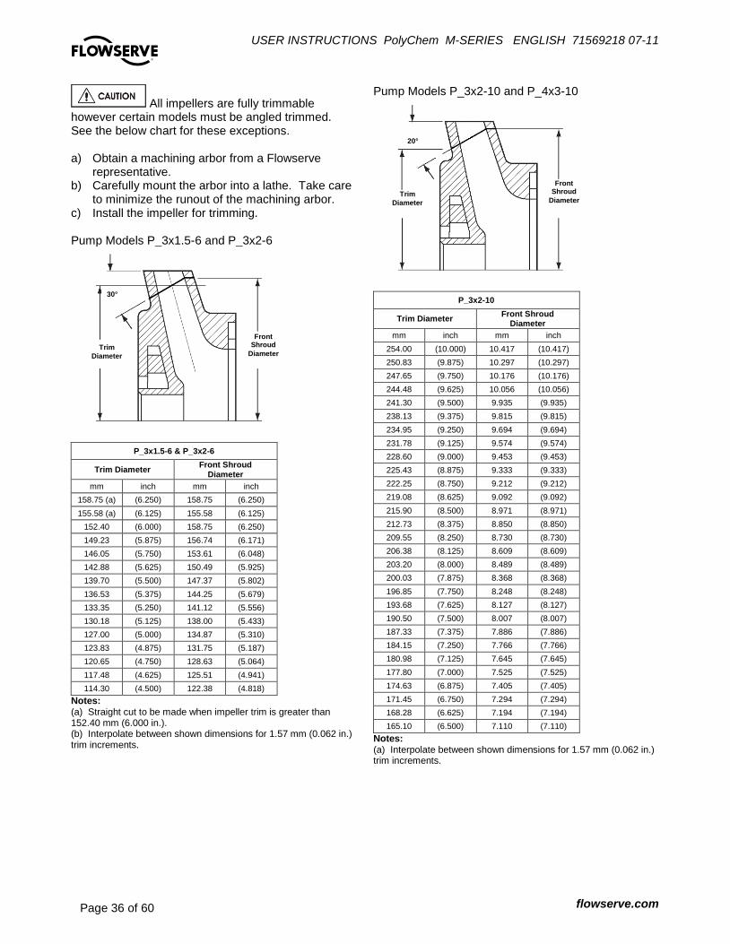
USER INSTRUCTIONS PolyChem M-SERIES ENGLISH 71569218 07-11
flowserve.com Page 36 of 60
®
All impellers are fully trimmable however certain models must be angled trimmed. See the below chart for these exceptions. a) Obtain a machining arbor from a Flowserve
representative. b) Carefully mount the arbor into a lathe. Take care
to minimize the runout of the machining arbor. c) Install the impeller for trimming. Pump Models P_3x1.5-6 and P_3x2-6
P_3x1.5-6 & P_3x2-6
Trim Diameter Front Shroud
Diameter mm inch mm inch
158.75 (a) (6.250) 158.75 (6.250)
155.58 (a) (6.125) 155.58 (6.125)
152.40 (6.000) 158.75 (6.250)
149.23 (5.875) 156.74 (6.171)
146.05 (5.750) 153.61 (6.048)
142.88 (5.625) 150.49 (5.925)
139.70 (5.500) 147.37 (5.802)
136.53 (5.375) 144.25 (5.679)
133.35 (5.250) 141.12 (5.556)
130.18 (5.125) 138.00 (5.433)
127.00 (5.000) 134.87 (5.310)
123.83 (4.875) 131.75 (5.187)
120.65 (4.750) 128.63 (5.064)
117.48 (4.625) 125.51 (4.941)
114.30 (4.500) 122.38 (4.818)
Notes: (a) Straight cut to be made when impeller trim is greater than 152.40 mm (6.000 in.). (b) Interpolate between shown dimensions for 1.57 mm (0.062 in.) trim increments.
Pump Models P_3x2-10 and P_4x3-10
P_3x2-10
Trim Diameter Front Shroud
Diameter mm inch mm inch
254.00 (10.000) 10.417 (10.417)
250.83 (9.875) 10.297 (10.297)
247.65 (9.750) 10.176 (10.176)
244.48 (9.625) 10.056 (10.056)
241.30 (9.500) 9.935 (9.935)
238.13 (9.375) 9.815 (9.815)
234.95 (9.250) 9.694 (9.694)
231.78 (9.125) 9.574 (9.574)
228.60 (9.000) 9.453 (9.453)
225.43 (8.875) 9.333 (9.333)
222.25 (8.750) 9.212 (9.212)
219.08 (8.625) 9.092 (9.092)
215.90 (8.500) 8.971 (8.971)
212.73 (8.375) 8.850 (8.850)
209.55 (8.250) 8.730 (8.730)
206.38 (8.125) 8.609 (8.609)
203.20 (8.000) 8.489 (8.489)
200.03 (7.875) 8.368 (8.368)
196.85 (7.750) 8.248 (8.248)
193.68 (7.625) 8.127 (8.127)
190.50 (7.500) 8.007 (8.007)
187.33 (7.375) 7.886 (7.886)
184.15 (7.250) 7.766 (7.766)
180.98 (7.125) 7.645 (7.645)
177.80 (7.000) 7.525 (7.525)
174.63 (6.875) 7.405 (7.405)
171.45 (6.750) 7.294 (7.294)
168.28 (6.625) 7.194 (7.194)
165.10 (6.500) 7.110 (7.110)
Notes: (a) Interpolate between shown dimensions for 1.57 mm (0.062 in.) trim increments.
Front Shroud
Diameter Trim
Diameter
30°
20°
Front Shroud
Diameter Trim
Diameter

USER INSTRUCTIONS PolyChem M-SERIES ENGLISH 71569218 07-11
flowserve.com Page 37 of 60
®
P_4x3-10
Trim Diameter Front Shroud
Diameter mm inch mm Inch
254.00 (10.000) N/A N/A
250.83 (9.875) N/A N/A
247.65 (9.750) 265.31 (10.445)
244.48 (9.625) 262.27 (10.325)
241.30 (9.500) 259.23 (10.206)
238.13 (9.375) 256.18 (10.086)
234.95 (9.250) 253.14 (9.966)
231.78 (9.125) 250.10 (9.847)
228.60 (9.000) 247.06 (9.727)
225.43 (8.875) 244.02 (9.607)
222.25 (8.750) 240.98 (9.487)
219.08 (8.625) 237.94 (9.368)
215.90 (8.500) 234.90 (9.248)
212.73 (8.375) 231.86 (9.128)
209.55 (8.250) 228.82 (9.009)
206.38 (8.125) 225.78 (8.889)
203.20 (8.000) 222.73 (8.769)
200.03 (7.875) 219.69 (8.649)
196.85 (7.750) 216.65 (8.530)
193.68 (7.625) 213.61 (8.410)
190.50 (7.500) 210.57 (8.290)
187.33 (7.375) 207.53 (8.170)
184.15 (7.250) 204.49 (8.051)
180.98 (7.125) 201.45 (7.931)
177.80 (7.000) 198.40 (7.811)
174.63 (6.875) 195.37 (7.692)
171.45 (6.750) 192.52 (7.580)
168.28 (6.625) 189.96 (7.479)
165.10 (6.500) 187.77 (7.393)
Notes: Interpolate between shown dimensions for 1.57 mm (0.062 in.) trim increments.
Figure 6-7: Group A and 1 pumps
Figure 6-8: Group B and 2 pumps
6.7 Pump removal and disassembly a) Before performing any maintenance, disconnect
the driver from its power supply and lock it off line.
Lock out power to driver to prevent personal injury. b) Close the discharge and suction valves, and
drain all liquid from the pump. c) Close all valves on auxiliary equipment and
piping, then disconnect all auxiliary piping. d) Decontaminate the pump as necessary.
If Flowserve PolyChem M-series pumps contain dangerous chemicals, it is important to follow plant safety guidelines to avoid personal injury or death.
Small amounts of liquid may be trapped in the casing and/or containment area. Proper decontamination is the responsibility of the user.
Drain and flush the pump before proceeding. The PolyChem M-series pump is designed to handle corrosive, toxic, and hazardous process fluids and may need to be decontaminated prior to any disassembly

USER INSTRUCTIONS PolyChem M-SERIES ENGLISH 71569218 07-11
flowserve.com Page 38 of 60
®
6.7.1 Pump removal 6.7.1.1 Long-coupled PolyChem M-series
pumps a) Remove coupling guard. b) Remove the spacer from the spacer coupling. c) Remove the cap screws holding the bearing
housing and casing feet to the baseplate. d) Remove the fasteners attaching the suction and
discharge piping to the pump. e) Attach lifting equipment to the pump, placing it in
light tension to support the pump. f) Move the pump assembly away from the piping
(towards the motor) and rotate the unit out. g) The pump can now be moved to the repair shop. 6.7.1.2 Close-coupled PolyChem M-series
pumps a) Remove the fasteners holding the motor and or
lantern and casing feet to the baseplate. b) Remove the fasteners attaching the suction and
discharge piping to the pump. c) Attach lifting equipment to the pump, placing it in
light tension to support the pump. d) Move the pump assembly away from the piping. e) The pump can now be moved to the repair shop. 6.7.2 Pump removal – less casing
Group A & 1 pumps are assembled vertically and the casing is required during the process. Therefore is is strongly recommended that the entire pump is removed as described in 6.7.1. above
Group B & 2 pumps can be removed, leaving the casing installed in the piping, as described in 6.7.2.1 and 6.7.2.2.
6.7.2.1 Long-coupled PolyChem M-series
pumps a) Remove coupling guard. b) Remove the spacer from the spacer coupling. c) Remove the cap screw(s) holding the bearing
housing foot to the baseplate. d) Attach lifting equipment to the pump, placing it in
light tension to support the pump when it is removed from the casing.
e) Remove all casing stud nuts [6572]. f) Move the pump assembly away from the casing
(towards the motor) and rotate the unit out, leaving the casing in place (Figure 6-9).
Figure 6-9
g) Inspect the casing [1100] and the thrust bearing
bushing [3041] located in the casing for wear, corrosion, or defects.
h) The pump less casing [1100] can now be moved to the repair shop.
6.7.2.2 Close-coupled PolyChem M-series
pumps a) Remove the fasteners holding the motor and or
lantern to the baseplate. b) Attach lifting equipment to the pump, placing it in
light tension to support the pump when it is removed from the casing.
c) Remove all casing stud nuts [6572]. d) Move the pump assembly away from the casing,
leaving the casing in place (Figure 6-10). Figure 6-10
e) Inspect the casing [1100] and the thrust bearing
bushing [3041] for wear, corrosion, or defects. f) The pump less casing [1100] can now be moved
to the repair shop.

USER INSTRUCTIONS PolyChem M-SERIES ENGLISH 71569218 07-11
flowserve.com Page 39 of 60
®
6.7.3 Drive end removal - without breaking process containment
By following the steps in section 6.7.3.1 or 6.7.3.2, the process fluid is contained and the power end can be completely removed. This procedure does not preclude the use of personal protective gear. Personnel should follow their standard plant safety practices.
The magnetic coupling will remain engaged even after the fasteners that attach the drive end to the wet end have been removed. This is due to the strong radial and axial forces associated with the magnetic coupling. 7
Do not attempt to remove the drive end from the wet end without using the jackbolts. The magnetic force can cause severe personal injury.
Be sure to separate the inner and outer magnet assemblies evenly. Cocking of the two can result in serious damage to the magnets and/or containment shell. It is best to alternatively give each bolt a turn to ensure proper and even separation. 6.7.3.1 Long-coupled PolyChem M-series
pumps Figure 6-11: Group A and 1 pumps
Figure 6-12: Group B and 2 pumps
a) Remove coupling guard. b) Remove the spacer coupling. c) Loosen the cap screw(s) holding the bearing
housing foot to the baseplate. d) To remove the power end from the wet end, on
Group A and 1 pumps remove the four (4) bearing housing/lantern fasteners [6570.6]. On Group B and 2 pumps remove the six (6) bearing housing/bearing holder fasteners [6570.8].
e) Screw the two (2) square head jackbolts [6575] in the lantern (Group A and 1 pumps) or bearing housing (Group B and 2 pumps) through the threaded holes until each comes into contact with its mating part. (see figure 6-11 and 6-12). Continue to screw all jackbolts in evenly to detach the wet end from the power end. (Figure 6-13 and 6-14)
It may be necessary to move the motor to complete step e). f) The power end can now be moved to the repair
shop. Figure 6-13: Group A and 1 pumps
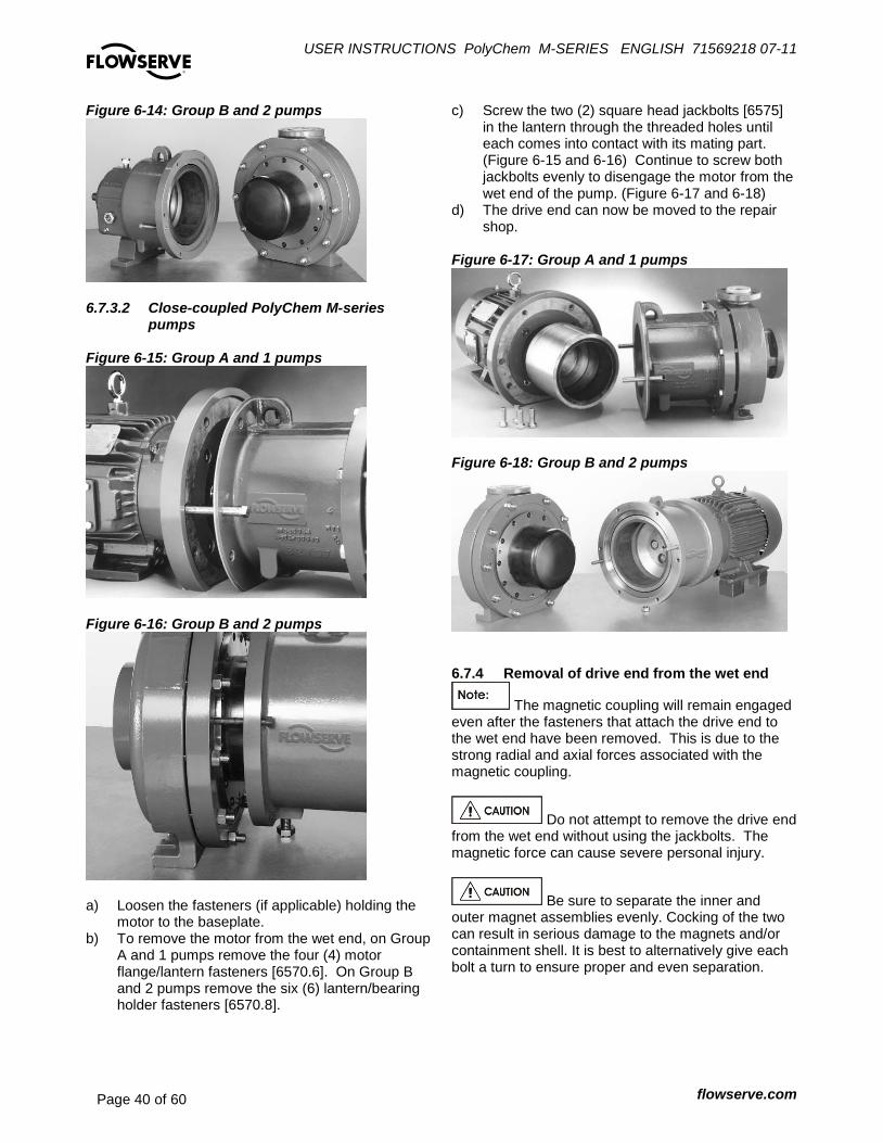
USER INSTRUCTIONS PolyChem M-SERIES ENGLISH 71569218 07-11
flowserve.com Page 40 of 60
®
Figure 6-14: Group B and 2 pumps
6.7.3.2 Close-coupled PolyChem M-series
pumps Figure 6-15: Group A and 1 pumps
Figure 6-16: Group B and 2 pumps
a) Loosen the fasteners (if applicable) holding the
motor to the baseplate. b) To remove the motor from the wet end, on Group
A and 1 pumps remove the four (4) motor flange/lantern fasteners [6570.6]. On Group B and 2 pumps remove the six (6) lantern/bearing holder fasteners [6570.8].
c) Screw the two (2) square head jackbolts [6575] in the lantern through the threaded holes until each comes into contact with its mating part. (Figure 6-15 and 6-16) Continue to screw both jackbolts evenly to disengage the motor from the wet end of the pump. (Figure 6-17 and 6-18)
d) The drive end can now be moved to the repair shop.
Figure 6-17: Group A and 1 pumps
Figure 6-18: Group B and 2 pumps
6.7.4 Removal of drive end from the wet end
The magnetic coupling will remain engaged even after the fasteners that attach the drive end to the wet end have been removed. This is due to the strong radial and axial forces associated with the magnetic coupling.
Do not attempt to remove the drive end from the wet end without using the jackbolts. The magnetic force can cause severe personal injury.
Be sure to separate the inner and outer magnet assemblies evenly. Cocking of the two can result in serious damage to the magnets and/or containment shell. It is best to alternatively give each bolt a turn to ensure proper and even separation.
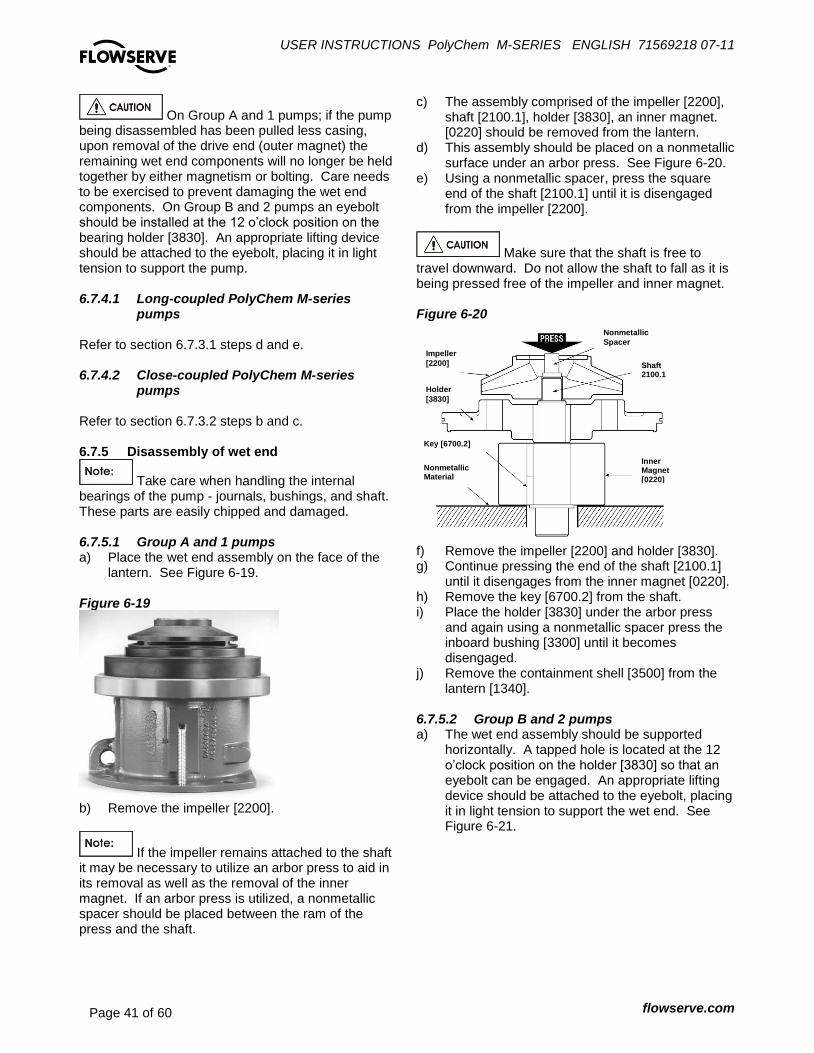
USER INSTRUCTIONS PolyChem M-SERIES ENGLISH 71569218 07-11
flowserve.com Page 41 of 60
®
On Group A and 1 pumps; if the pump being disassembled has been pulled less casing, upon removal of the drive end (outer magnet) the remaining wet end components will no longer be held together by either magnetism or bolting. Care needs to be exercised to prevent damaging the wet end components. On Group B and 2 pumps an eyebolt should be installed at the 12 o’clock position on the bearing holder [3830]. An appropriate lifting device should be attached to the eyebolt, placing it in light tension to support the pump. 6.7.4.1 Long-coupled PolyChem M-series
pumps Refer to section 6.7.3.1 steps d and e. 6.7.4.2 Close-coupled PolyChem M-series
pumps Refer to section 6.7.3.2 steps b and c. 6.7.5 Disassembly of wet end
Take care when handling the internal bearings of the pump - journals, bushings, and shaft. These parts are easily chipped and damaged. 6.7.5.1 Group A and 1 pumps a) Place the wet end assembly on the face of the
lantern. See Figure 6-19. Figure 6-19
b) Remove the impeller [2200].
If the impeller remains attached to the shaft it may be necessary to utilize an arbor press to aid in its removal as well as the removal of the inner magnet. If an arbor press is utilized, a nonmetallic spacer should be placed between the ram of the press and the shaft.
c) The assembly comprised of the impeller [2200], shaft [2100.1], holder [3830], an inner magnet. [0220] should be removed from the lantern.
d) This assembly should be placed on a nonmetallic surface under an arbor press. See Figure 6-20.
e) Using a nonmetallic spacer, press the square end of the shaft [2100.1] until it is disengaged from the impeller [2200].
Make sure that the shaft is free to travel downward. Do not allow the shaft to fall as it is being pressed free of the impeller and inner magnet. Figure 6-20
f) Remove the impeller [2200] and holder [3830]. g) Continue pressing the end of the shaft [2100.1]
until it disengages from the inner magnet [0220]. h) Remove the key [6700.2] from the shaft. i) Place the holder [3830] under the arbor press
and again using a nonmetallic spacer press the inboard bushing [3300] until it becomes disengaged.
j) Remove the containment shell [3500] from the lantern [1340].
6.7.5.2 Group B and 2 pumps a) The wet end assembly should be supported
horizontally. A tapped hole is located at the 12 o’clock position on the holder [3830] so that an eyebolt can be engaged. An appropriate lifting device should be attached to the eyebolt, placing it in light tension to support the wet end. See Figure 6-21.
Nonmetallic Material
Key [6700.2]
Holder
[3830]
Impeller
[2200]
Inner Magnet [0220]
Shaft 2100.1
Nonmetallic
Spacer

USER INSTRUCTIONS PolyChem M-SERIES ENGLISH 71569218 07-11
flowserve.com Page 42 of 60
®
Figure 6-21
The retainer ring [2530] is manufactured from carbon steel and may attach to the containment shell [3500] upon removal due to the presence of magnets in the inner magnet assembly. b) Remove the twelve (12) retainer
ring/containment shell cap screws [6570.7]. Remove the retainer ring [2530]. In the event the retainer ring is lodged in place, two (2) tapped holes have been provided on this ring to aid in its removal. The recently removed cap screws can be used for this purpose.
c) Remove the containment shell [3500]. See Figure 6-22.
Figure 6-22
d) Remove the impeller [2200].
If the impeller remains attached to the shaft it may be necessary to utilize an arbor press to aid in its removal as well as the removal of the inner
magnet. If an arbor press is utilized, a nonmetallic spacer should be placed between the ram of the press and the shaft. e) The assembly comprised of the impeller [2200],
shaft [2100.1], holder [3830], and inner magnet [0220] should be placed on a nonmetallic surface under an arbor press. See Figure 6-23.
f) Using a nonmetallic spacer, press the end of the shaft [2100.1] until it is disengaged from the impeller [2200].
Make sure that the shaft is free to travel downward. Do not allow the shaft to fall as it is being pressed free of the impeller and inner magnet. Figure 6-23
g) Remove the impeller [2200] and holder [3830]. h) Continue pressing the end of the shaft [2100.1]
until it disengages from the inner magnet [0220]. i) Remove the keys [6700.2] from the shaft. j) Place the holder [3830] under the arbor press in
the same orientation as shown in Figure 6-23. Using a nonmetallic spacer press the inboard bushing [3300] until it becomes disengaged.
k) Remove o-ring [4610.2] from holder [3830] and discard.
6.7.6 Disassembly of drive end
Be aware of strong magnetic forces of the outer magnets. Keep magnetic material away from these magnets. Observe previous warnings concerning these magnets.
Impeller
[2200]
Holder
[3830]
Nonmetallic
Material
Inner Magnet [0220]
Key [6700.2]
Shaft
[2100.1]
Nonmetallic
Spacer
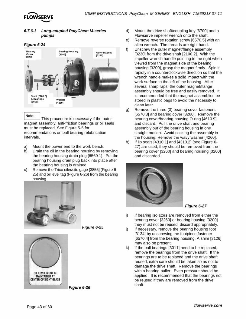
USER INSTRUCTIONS PolyChem M-SERIES ENGLISH 71569218 07-11
flowserve.com Page 43 of 60
®
6.7.6.1 Long-coupled PolyChem M-series pumps
Figure 6-24
This procedure is necessary if the outer magnet assembly, anti-friction bearings or oil seals must be replaced. See Figure 5-5 for recommendations on ball bearing relubrication intervals. a) Mount the power end to the work bench. b) Drain the oil in the bearing housing by removing
the bearing housing drain plug [6569.1]. Put the bearing housing drain plug back into place after the bearing housing is drained.
c) Remove the Trico oiler/site gage [3855] (Figure 6-25) and oil level tag (Figure 6-26) from the bearing housing.
Figure 6-25
Figure 6-26
d) Mount the drive shaft/coupling key [6700] and a Flowserve impeller wrench onto the shaft.
e) Remove reverse rotation screw [6570.5] with an allen wrench. The threads are right hand.
f) Unscrew the outer magnet/flange assembly [0230] from the drive shaft [2100.2]. With the impeller wrench handle pointing to the right when viewed from the magnet side of the bearing housing [3200], grasp the magnet firmly. Spin it rapidly in a counterclockwise direction so that the wrench handle makes a solid impact with the work surface to the left of the housing. After several sharp raps, the outer magnet/flange assembly should be free and easily removed. It is recommended that the magnet assemblies be stored in plastic bags to avoid the necessity to clean later.
g) Remove the three (3) bearing cover fasteners [6570.3] and bearing cover [3260]. Remove the bearing cover/bearing housing O-ring [4610.9] and discard. Pull the drive shaft and bearing assembly out of the bearing housing in one straight motion. Avoid cocking the assembly in the housing. Remove the wavy washer [4260].
h) If lip seals [4310.1] and [4310.2] (see Figure 6-27) are used, they should be removed from the bearing cover [3260] and bearing housing [3200] and discarded.
Figure 6-27 i) If bearing isolators are removed from either the
bearing cover [3260] or bearing housing [3200] they must not be reused, discard appropriately.
j) If necessary, remove the bearing housing foot [3134] by unscrewing the footpiece fastener [6570.4] from the bearing housing. A shim [3126] may also be present.
k) If the ball bearings [3011] need to be replaced, remove the bearings from the drive shaft. If the bearings are to be replaced and the drive shaft reused, extra care should be taken so as not to damage the drive shaft. Remove the bearings with a bearing puller. Even pressure should be applied. It is recommended that the bearings not be reused if they are removed from the drive shaft.
Bearing Cover [3260]
Bearing Housing
[3200] Outer Magnet [0230]
Shaft [2100.2] & Bearings [3011]
Washer
[4260]

USER INSTRUCTIONS PolyChem M-SERIES ENGLISH 71569218 07-11
flowserve.com Page 44 of 60
®
Keep contaminants out of the bearing housing and bearings. 6.7.6.2 Close-coupled PolyChem M-series
pumps Figure 6-28: Group A and 1 pumps
Figure 6-29: Group B and 2 pumps
This procedure is necessary only if the outer magnet assembly [0230] or motor must be replaced. Group A and 1 pumps: a) Loosen the set screw that attaches the outer
magnet assembly [0230] to the motor shaft. See Figure 6-28.
b) Remove the outer magnet assembly [0230] from the motor shaft. As a disassembly aide, a threaded hole has been provided in the center of the outer magnet flange [0231] to enable the outer magnet flange to be jacked off of the motor shaft. One of the square head jackscrews [6575] from the lantern [1340] can be used for this step.
c) Remove the fasteners [6570.9] that attach the outer magnet flange [0231] to the hub [7200].
d) To remove the motor flange [0231], remove the four (4) motor flange/motor fasteners [6570.4].
e) The outer magnet flange [0231] can be separated from the outer magnet [0230] by removing fasteners [6570.3].
Group B and 2 pumps: a) Loosen the fasteners [6570.9] that attaches the
outer magnet assembly [0230] to the hub [7200]. See Figure 6-29.
b) To remove the lantern [1340], remove the four (4) lantern/motor fasteners [6570.4].
c) Loosen the set screws that attaches the hub [6814] to the motor, pull the hub off the shaft.
d) The outer magnet flange [0231] can be separated from the outer magnet [0230] by removing fasteners [6570.3].
6.8 Examination of parts Cleaning/inspection All parts should be thoroughly cleaned and inspected. New anti-friction bearings, O-rings, gaskets and lip seals should be used (if so equipped). Any parts that show wear or corrosion should be replaced with new genuine Flowserve parts.
It is important that only non-flammable, non-contaminated cleaning fluids are used. These fluids must comply with plant safety and environmental guidelines. Critical measurements and tolerances To maximize reliability of pumps, it is important that certain parameters and dimensions are measured and maintained within specified tolerances. It is important that all parts be checked. Any parts that do not conform to the specifications should be replaced with new Flowserve parts. Parameters that should be checked by users Flowserve recommends that the user check the condition of the individual pump components whenever maintenance is performed. It is described in more detail below.
Jackbolt
[6575] Hub
[7200]
Outer Magnet
Flange [0231]
Lantern
[1340]
Hub
[7200]
Fastener & Lockwasher
Outer Magnet
Flange [0231]

USER INSTRUCTIONS PolyChem M-SERIES ENGLISH 71569218 07-11
flowserve.com Page 45 of 60
®
6.8.1 Wet End a) Inspect the bushings, thrust journals and shaft
for wear. Total diametrical and axial wear limits are shown in Figure 6-30.
b) Inspect the casing, impeller, holder, inner magnet and containment shell for wear, corrosion and defects. The nominal liner thickness for all components is 3.18 mm (0.125 inches).
Figures 6-31 through 6-36 have been provided as a guide for identifying the features listed in the table.
Figure 6-31: Shell
Figure 6-32: Shaft
Figure 6-33: Bushing
Figure 6-34: Inner Magnet
Figure 6-30: Wet end allowable wear
Axial Allowable Bearing Wear (total) 0.38 mm (0.015 in)
Diametrical Allowable Bearing Wear (total) 0.61 mm (0.024 in)
Liner Allowable Wear 25% of thickness
AS NEW DIMENSIONS – NOMIINAL
AXIAL BEARING FEATURES
Group A and 1 Group B and 2
Thrust Journal and Bushing Thickness
4.78 (0.188) 6.35 (0.250)
Shell Thrust Bushing Depth 95.89 (3.775) 112.27 (4.420)
Shaft Shoulder Thickness 5.21 (0.205) 7.9 (0.31)
Pump Model Impeller Height Casing Depth
32-160 49.99 (1.968) 70.79 (2.787)
65-160 50.50 (1.988) 85.24 (3.356)
40-200 51.26 (2.018) 84.89 (3.342)
1.5x1-6 48.97 (1.928) 74.73 (2.942)
3x1.5-6 52.27 (2.058) 78.87 (3.105)
3x2-6 52.27 (2.058) 78.87 (3.105)
1.5x1-8 49.48 (1.948) 75.82 (2.985)
32-250 57.66 (2.270) 92.91 (3.658)
50-250 58.17 (2.290) 93.24 (3.671)
65-250 63.25 (2.490) 98.08 (3.862)
2x1-10 57.66 (2.270) 95.76 (3.770)
3x2-10 56.90 (2.240) 94.92 (3.737)
4x3-10 63.25 (2.490) 101.35 (3.990)
RADIAL BEARING FEATURES
Group A and 1 Group B and 2
Bushing Inside Diameter 38.13 (1.501) 50.04 (1.970)
Shaft Outside Diameter 38.087 (1.4995) 50.000 (1.9685)
ADDITIONAL COMPONENT FEATURES
Group A and 1 Group B and 2
Shell Inside Diameter 124.89 (4.917) 195.83 (7.71)
Inner Magnet
O.D. 121.92 (4.800) 190.04 (7.482)
I.D. 44.450 (1.7500) 50.533 (1.9895)
Width 12.75 (0.502) 12.75 (0.502)
Key Width 12.57 (0.495) 12.57 (0.495)
Note: Dimensions shown above are in millimeters (inches).
Bushing
I.D.
Thrust Bearing Depth
Inside
Diameter
Bushing I.D.
Bearing Holder
Shoulder Thickness
Outside
Diameter
Outside
Diameter
Width
Inside Diameter
Outside Diameter
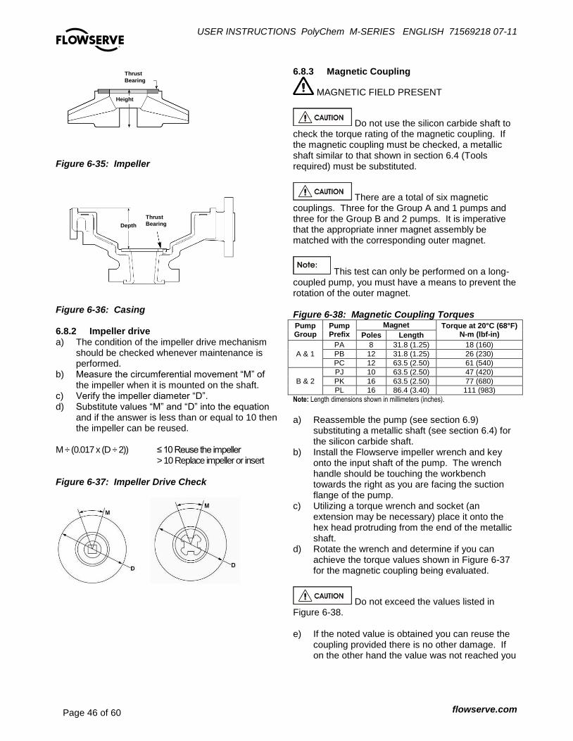
USER INSTRUCTIONS PolyChem M-SERIES ENGLISH 71569218 07-11
flowserve.com Page 46 of 60
®
Figure 6-35: Impeller
Figure 6-36: Casing 6.8.2 Impeller drive a) The condition of the impeller drive mechanism
should be checked whenever maintenance is performed.
b) Measure the circumferential movement “M” of the impeller when it is mounted on the shaft.
c) Verify the impeller diameter “D”. d) Substitute values “M” and “D” into the equation
and if the answer is less than or equal to 10 then the impeller can be reused.
M ÷ (0.017 x (D ÷ 2)) ≤ 10 Reuse the impeller > 10 Replace impeller or insert Figure 6-37: Impeller Drive Check
6.8.3 Magnetic Coupling
MAGNETIC FIELD PRESENT
Do not use the silicon carbide shaft to check the torque rating of the magnetic coupling. If the magnetic coupling must be checked, a metallic shaft similar to that shown in section 6.4 (Tools required) must be substituted.
There are a total of six magnetic couplings. Three for the Group A and 1 pumps and three for the Group B and 2 pumps. It is imperative that the appropriate inner magnet assembly be matched with the corresponding outer magnet.
This test can only be performed on a long-coupled pump, you must have a means to prevent the rotation of the outer magnet. Figure 6-38: Magnetic Coupling Torques Pump Group
Pump Prefix
Magnet Torque at 20°C (68°F) N-m (lbf-in) Poles Length
A & 1
PA 8 31.8 (1.25) 18 (160)
PB 12 31.8 (1.25) 26 (230)
PC 12 63.5 (2.50) 61 (540)
B & 2
PJ 10 63.5 (2.50) 47 (420)
PK 16 63.5 (2.50) 77 (680)
PL 16 86.4 (3.40) 111 (983)
Note: Length dimensions shown in millimeters (inches). a) Reassemble the pump (see section 6.9)
substituting a metallic shaft (see section 6.4) for the silicon carbide shaft.
b) Install the Flowserve impeller wrench and key onto the input shaft of the pump. The wrench handle should be touching the workbench towards the right as you are facing the suction flange of the pump.
c) Utilizing a torque wrench and socket (an extension may be necessary) place it onto the hex head protruding from the end of the metallic shaft.
d) Rotate the wrench and determine if you can achieve the torque values shown in Figure 6-37 for the magnetic coupling being evaluated.
Do not exceed the values listed in Figure 6-38. e) If the noted value is obtained you can reuse the
coupling provided there is no other damage. If on the other hand the value was not reached you
Thrust
Bearing
Width
Depth
Thrust
Bearing
Thrust
Bearing
Height

USER INSTRUCTIONS PolyChem M-SERIES ENGLISH 71569218 07-11
flowserve.com Page 47 of 60
®
will need to replace either the inner (most likely) or outer magnet assembly.
6.8.4 Power End a) Inspect the outer magnet for wear and condition
of potting compound that exists between the magnet poles.
b) Inspect the anti-friction bearings for scoring, pitting, scratches or rust. If any of these conditions exists or if the bearings have been removed from the shaft the bearings should be replaced.
c) In order to ensure proper bearing fits, the shaft (OD), bearings (ID and OD), and bearing housing (ID) should be checked. A micrometer can be used to check the OD dimensions and an inside caliper the ID dimensions. See Figure 6-39.
Figure 6-39
PolyChem M-series
Feature mm (in) Group A and 1 Group B and 2
Bearing
OD 79.992/79.987
(3.1493/3.1491) 110.000/109.985 (43304/43301)
ID 35.000/34.989
(1.3780/1.3775) 50.000/49.987
(1.9685/1.9680)
Shaft OD 35.014/35.004
(1.3785/1.3781) 50.013/50.003
(1.9690/1.9686)
Housing ID 80.020/80.005
(3.1504/3.1498) 110.023/110.007 (4.3316/4.3310)
Fit Bearing/Housing
0.033L/0.013L (0.0013L/0.0005L)
0.038L/0.008L (0.0015L/0.0003L)
Fit Bearing/Shaft
0.025T/0.004T (0.0010T/0.0001T)
0.026T/0.003T (0.0010T/0.0001T)
6.8.4.1 Alignment Misalignment of the pump and motor shafts can cause the following problems:
Failure of the motor and/or pump bearings
Failure of the coupling
Excessive vibration/noise The schematics below show the technique for a typical rim and face alignment using a dial indicator. It is important that this alignment be done after the flanges are loaded, and at typical operating temperatures. If proper alignment cannot be maintained a close coupled arrangement and/or stilt/spring mounting should be considered.
Alignment Many companies today are using laser alignment which is a more sophisticated and accurate technique. With this method a laser and sensor measure misalignment. This is fed to a computer with a graphic display that shows the required adjustment for each of the motor feet. See section 4.8 for recommended final shaft alignment limits. 6.8.4.2 Vibration analysis Vibration analysis is a type of condition monitoring where a pump’s vibration “signature” is monitored on a regular, periodic basis. The primary goal of vibration analysis is extension on MTBPM. By using this tool Flowserve can often determine not only the existence of a problem before it becomes serious, but also the root cause and possible solution. Modern vibration analysis equipment not only detects if a vibration problem exists, but can also suggest the cause of the problem. On a centrifugal pump, these causes can include the following: unbalance, misalignment, defective bearings, resonance, hydraulic forces, cavitation and recirculation. Once identified, the problem can be corrected, leading to increased MTBPM for the pump. Flowserve does not make vibration analysis equipment; however Flowserve strongly urges customers to work with an equipment supplier or consultant to establish an on-going vibration analysis program.
6.9 Assembly of pump
It is important that all pipe threads be sealed properly. Flowserve does not recommend the use of PTFE tape as a thread sealant. Flowserve has investigated and tested alternate sealants and has identified two that provide an effective seal and have the same chemical resistance as the tape. These are La-co Slic-Tite and Bakerseal. Both products contain finely ground PTFE particles in

USER INSTRUCTIONS PolyChem M-SERIES ENGLISH 71569218 07-11
flowserve.com Page 48 of 60
®
an oil based carrier. They are supplied in a paste form which is brushed onto the male pipe threads. Flowserve recommends using one of these paste sealants. Full thread length engagement is required for all fasteners.
Refer to Figure 6-4 for recommended bolt torques. 6.9.1 Power end assembly – Long Coupled 6.9.1.1 Bearing installation Mounting of bearings on shafts must be done in a clean environment. Bearing and power end life can be drastically reduced if even very small foreign particles work their way into the bearings. Wear clean gloves. Bearings should be removed from their protective packaging only immediately before assembly to limit exposure to possible contamination. After removing the packaging they should only come in contact with clean hands, fixtures, tools and work surfaces. The chart shown in Figure 6-40 gives the part numbers for bearings in Flowserve PolyChem pumps. Note that the term “inboard bearing” refers to the bearing nearest to the casing. “Outboard bearing” refers to the bearing nearest to the motor.
Both bearings have a slight interference fit which requires that they be pressed on the shaft with an arbor or hydraulic press. Even force should be applied to only the inner race. Never press on the outer race, as the force will damage the balls and races. An alternate method of installing bearings is to heat the bearings to 93 °C (200 °F) by means of an oven or induction heater. With this approach the bearing must be quickly positioned on the shaft. Never heat the bearings above 110°C (230°F). To do so will likely cause the bearing fits to permanently change, leading to early failure.
Figure 6-40: Flowserve PolyChem M-series anti-friction bearings
Pump Group
Type of bearing Inboard and outboard
single row, deep groove
A & 1
Oil bath / mist – Open
1 6307-C3
Greased for life – double shielded
2 6307-2ZC3
B & 2
Oil bath / mist – Open
1 6310-C3
Greased for life – double shielded
2 6310-2ZC3
Notes: 1) These bearings are open on both sides. They are lubricated by oil bath or oil mist. 2) These bearings are shielded on both sides. They come pre-greased by the bearing manufacturer. The user does not need to regrease these bearings. The shields do not actually contact the bearing race, so no heat is generated. 3) All bearing configurations are supplied only with steel cages
a) Install the inboard bearing [3011.1] on the shaft
[2100.2] until it is positioned against the shoulder. b) Allow the inboard bearing to cool before installing
the outboard bearing. c) Install the outboard bearing [3011.2] on the shaft
[2100.2] until it is positioned against the shoulder. d) Allow the outboard bearing to cool and then check
bearings for ease of rotation. 6.9.1.2 Power end seals Lip seals If lip seals were used install new lip seals in the bearing cover [3260] and the housing [3200]. The lip seals [4310.1 and 4310.2] are double lip style, the cavity between these two lips should be
1/2 to
2/3 filled with
grease. When installing this part, the large metal face on the lip seal must face away from the bearings. Labyrinth seals The following are general installation instructions regarding the VBXX Inpro seal. Follow the instructions provided with the seal by the manufacturer. The elastomer O-ring located on the OD of the seal has been sized to overfill the groove in which it is located. When installing the seal into its corresponding housing, in addition to compressing the O-ring a certain amount of material may shear off. This sheared material should be removed. An arbor press should be used to install the seal. Install the inboard seal in the bore of the bearing housing with the single expulsion port positioned at the 6 o’clock position.

USER INSTRUCTIONS PolyChem M-SERIES ENGLISH 71569218 07-11
flowserve.com Page 49 of 60
®
Install the outboard seal in the bore of the bearing cover with the single expulsion port positioned at the 6 o’clock position. Magnetic seals Follow the installation instructions provided by the manufacturer. 6.9.1.3 Bearing cover/shaft/power end assembly a) Clean the interior surfaces of the bearing
housing and cover with a non-flammable solvent cleaner.
b) Place the wavy washer [4260] in the bearing housing [3200]. Slide the shaft [2100.2] with anti-friction bearings installed into the bearing housing [3200] (Figure 6-24).
The axial location of the shaft/anti-friction bearing assembly is accomplished after the bearing cap is installed and the wavy washer is compressed. The compression results in preloading the anti-friction bearings which is essential for proper bearing operation. c) Install a new O-ring [4610.9] into the bearing
cover [3260] utilizing a small amount of grease to hold it in place.
d) Place the bearing cover [3260] onto the shaft [2100.2] slide it towards the bearing housing [3200] and then secure it with the three (3) fasteners [6570.3].
e) Reinstall the following items onto the bearing housing; oil level tag (Figure 6-25 and 6-26) and combination Trico oiler/site gage [3855], vent/breather [6569.2] and drain plug [6569.1].
f) Attach the outer magnet flange [0231] to the outer magnet [0230] using socket head cap screws [6570.3].
g) Install the Flowserve impeller wrench and key onto the input shaft of the pump. The wrench handle should be touching the workbench towards the right as you are facing the suction flange of the pump.
h) Screw the outer magnet flange assembly onto the drive shaft.
i) Using gloves, raise the impeller wrench until it is parallel with the work bench (but still facing towards the right as you face the suction flange of the pump), spin the outer magnet rapidly in a clockwise direction to impact the impeller
wrench on the work bench. After several sharp raps, the outer magnet assembly should be tight.
The threads are right hand. j) Insert the flat head cap screw [6570.8] into the
center of the outer magnet flange and tighten. Again the threads are right hand tight.
k) The assembly of the power end is complete. 6.9.2 Power end assembly – Close Coupled 6.9.2.1 Group A and 1 a) Attach a new motor gasket [4590.2] and lantern
gasket [4590.1] to the motor flange [6540]. b) Mount the motor flange [6540] to the motor with
four (4) socket head cap screws [6570.4] see Figure 6-17.
c) Attach the outer magnet flange [0231] to the outer magnet [0230] using socket head cap screws [6570.3].
d) Attach the hub [7200] to the outer magnet assembly using the four (4) fasteners [6570.9] supplied with the hub, see Figure 6-28.
e) Place the key supplied with the motor in the motor keyway and mount the outer magnet assembly onto the motor shaft. Engage the assembly onto the motor shaft till the face of the outer magnet flange [6540] contacts the end of the shaft. This ensures the proper axial location of the magnet poles.
f) Tighten the set screw in the hub to secure the outer magnet assembly to the motor shaft.
6.9.2.2 Group B and 2 a) Attach a new motor gasket [4590] to the lantern
[1340]. b) Place the key supplied with the motor in the
motor keyway and mount the hub [7200] to the shaft. The end of the hub must be aligned with end of the shaft, see figure 6-41.
Figure 6-41
c) Tighten the set crews in the hub to secure it to
the motor shaft, figure 6-29.
Hub [7200] Installation
Studs
Hub and end of motor shaft must
be aligned
Motor
shaft

USER INSTRUCTIONS PolyChem M-SERIES ENGLISH 71569218 07-11
flowserve.com Page 50 of 60
®
Install two (2) 5/8-11UNC-2B studs (180° apart) into the hub to aid in installation of the outer magnet assembly. These two studs will be later removed. d) Mount lantern [1340] to the motor with four (4)
hex head cap screws [6570.4]. e) Attach the outer magnet flange [0231] to the
outer magnet [0230] using socket head cap screws [6570.3].
f) Place the outer magnet assembly into the lantern [1340] and use the installation studs as a guide to support the assembly until two (2) of the fasteners [6570.9] and corresponding lock washers can be installed. See Figure 6-29
g) Remove the installation studs and replace them with the remaining two (2) fasteners [6570.9] and lock washers.
6.9.3 Wet end assembly The first part of these instructions pertain to both the Group A and 1 plus Group B and 2 pump models.
In the assembly of the wet end it will be necessary to utilize an arbor press to aid in the assembly of the silicon carbide bearings into their mating components. When utilizing an arbor press a nonmetallic spacer must be placed between the ram of the press and corresponding silicon carbide bearing. The spacer must be flat and the entire surface area of the component being pressed must be covered. a) The casing [1100] should placed on its suction
flange. The surface on which the suction flange is placed must be flat and care must be taken to protect the casing liner, see Figure 6-42.
Figure 6-42
b) Install pin [6810.2] into casing [1100] followed by
the installation of the thrust bushing [3041] taking care to align the slot with the pin.
c) Press the inboard bushing [3300] into the bearing holder [3830], see figure 6-43.
On Group A and 1 pumps take care to align the flat on the bushing with the flat on the bearing holder. On Group B and 2 pumps visually align the key slots in the bushing with the as molded keys in the bearing holder. Figure 6-43
d) Install key(s) [6700.2] into the key slot(s) located
on the silicon carbide shaft [2100.1]. e) Press the shaft [2100.1] into the inner magnet
[0220], see Figure 6-44. Figure 6-44
6.9.3.1 Group A and 1 a) Place the lantern [1340] on a work bench with
the flange incorporating the lifting lug towards the work bench, see Figure 6-45.
b) Install the containment shell [3500] into the lantern followed by the inner magnet/shaft assembly and then the bearing holder/bushing.
Non metallic
spacer
Casing
[1100]
Pin
[6810.2]
Thrust bushing
[3041]
Non metallic
spacer
Bushing
[3300]
Bearing holder [3830]
Non metallic
spacer
Key
[6700.2]
Inner Magnet
[818/220]
Shaft
[2100.1]

USER INSTRUCTIONS PolyChem M-SERIES ENGLISH 71569218 07-11
flowserve.com Page 51 of 60
®
Figure 6-45
c) Rotate the bearing holder [3830] so that holes
are located at the 3, 6, 9, and 12 o’clock positions with the flat being forced to be at the 12 o’clock position, which is in line with the lifting lug.
d) See section 6.6 for impeller assembly. e) Install the casing [1100] onto the lantern/bearing
holder with studs and nuts [6572 and 6580]. 6.9.3.2 Group B and 2 a) Install gasket [4610.1] into groove on bearing
holder [3830] b) To continue the assembly process the bearing
holder should be support horizontally. A tapped hole is located at the 12 o’clock position on the holder [3830] so that an eyebolt can be engaged. An appropriate lifting device should be attached to the eyebolt, placing it in light tension to support the wet end. See Figure 6-45.
Figure 6-45
c) Install the inner magnet/shaft assembly through
the bushing [3300] that is located in the bearing holder [3830].
d) Place the containment shell [3500] over the inner magnet followed by retaining ring [2530].
The retainer ring [2530] is manufactured from carbon steel and may attach to the containment shell [3500] upon installation due to the presence of magnets in the inner magnet assembly. e) Install and tighten the twelve (12) retainer
ring/containment shell cap screws [6570.7]. f) See section 6.6 for impeller assembly. g) Install the casing [1100] onto the bearing holder
with studs and nuts [6572 and 6580]. 6.9.4 Mounting the wet end to the power end
Do not attempt to assemble the drive end to the wet end without using the jackbolts. The magnetic force can cause severe personal injury.
Be sure to engage the inner and outer magnet assemblies evenly. Cocking of the two can result in serious damage to the magnets and/or containment shell. It is best to alternatively give each bolt a turn to ensure proper and even separation.
Thread the entire length of the square head jackbolts [6575] through the bearing housing or lantern. a) Slide the wet end towards the power end until
the jackbolts [6575] engage in the recess provided for it.
b) Turn the jackbolts [6575] counterclockwise to allow the wet end to slowly engage into the power end. Alternate from one bolt to the other to prevent the unit from cocking.
c) Once the mating surfaces are in contact, install fasteners [6570.6] for Group A and 1 and [6570.8] for Group B and 2.
Bearing holder [3830]
Bushing
[545.1/212]
Lantern
[1340]
Containment shell
[817/224]
Shaft
[2100.1]
Lifting
Lug
O.B.
Bushing
Impeller
[2200]
Non metallic
spacer

USER INSTRUCTIONS PolyChem M-SERIES ENGLISH 71569218 07-11
flowserve.com Page 52 of 60
®
7 FAULTS; CAUSES AND REMEDIES The following is a guide to troubleshooting problems with Flowserve PolyChem pumps. Common problems are analyzed and solutions offered. Obviously, it is impossible to cover every possible scenario. If a problem exists that is not covered by one of the examples, then refer to one of the books listed in section 10 Additional sources of information or contact a Flowserve sales engineer or distributor/representative for assistance.
FAULT SYMPTOM
Pump not reaching design flow rate
Pump not reaching design head (TDH)
No discharge or flow with pump running
Pump operates for short period, then loses prime
Excessive noise from wet end
Excessive noise from power end
Pump exhibits increased or higher than anticipated power consumption
Pump exhibits decreased or lower than anticipated power consumption
PROBABLE CAUSES POSSIBLE REMEDIES
Insufficient NPSH. (Noise may not be present.)
Recalculate NPSH available. It must be greater than the NPSH required by pump at desired flow. If not, redesign suction piping, holding number of elbows and number of planes to a minimum to avoid adverse flow rotation as it approaches the impeller.
System head greater than anticipated.
Reduce system head by increasing pipe size and/or reducing number of fittings. Increase impeller diameter. (nb: Increasing impeller diameter may require use of a larger motor.)
Entrained air. Air leak from atmosphere on suction side.
1. Check suction line gaskets and threads for tightness. 2. If vortex formation is observed in suction tank, install vortex breaker. 3. Check for minimum submergence
Entrained gas from process. Process generated gases may require larger pumps.
Speed too low. Check motor speed against design speed.
Direction of rotation wrong. After confirming wrong rotation, reverse any two of three leads on a three phase motor. The pump should be disassembled and inspected before it is restarted.
Impeller too small. Replace with proper diameter impeller. (NOTE: Increasing impeller diameter may require use of a larger motor.)
Plugged impeller, suction line or casing which may be due to a product or large solids.
1. Reduce length of fiber when possible. 2. Reduce solids in the process fluid when possible. 3. Consider larger pump.
Wet end parts (casing, bearing holder, impeller, containment shell) worn, corroded or missing.
Replace part or parts.
Not properly primed. Repeat priming operation, recheck instructions. If pump has run dry, disassemble and inspect the pump before operation.
Impeller rubbing. Check wet end bearings for wear.
Damaged bushings pump shaft, thrust bearings or impeller.
Replace damaged parts.
Abnormal fluid rotation due to complex suction piping.
Redesign suction piping, holding the number of elbows and planes to a minimum to avoid adverse fluid rotation as it approaches the impeller.
Magnetic coupling decoupled due to excessive temperature or excessive horsepower requirements.
1. Check process temperature to verify it’s within operating limits of pump.
2. Check horsepower required by the process to verify it is within the operating limits of the coupling size.
3. Replacement of the magnet assemblies may be necessary if the magnets overheated and were permanently damaged. A static torque test of the magnetic coupling may be necessary. Contact your Flowserve representative for details.
Inner magnet rubbing shell. Check for damaged or worn pump shaft and bushings.
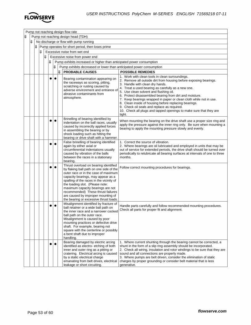
USER INSTRUCTIONS PolyChem M-SERIES ENGLISH 71569218 07-11
flowserve.com Page 53 of 60
®
Pump not reaching design flow rate
Pump not reaching design head (TDH)
No discharge or flow with pump running
Pump operates for short period, then loses prime
Excessive noise from wet end
Excessive noise from power end
Pump exhibits increased or higher than anticipated power consumption
Pump exhibits decreased or lower than anticipated power consumption
PROBABLE CAUSES POSSIBLE REMEDIES
Bearing contamination appearing on the raceways as scoring, pitting, scratching or rusting caused by adverse environment and entrance of abrasive contaminants from atmosphere.
1. Work with clean tools in clean surroundings. 2. Remove all outside dirt from housing before exposing bearings. 3. Handle with clean dry hands. 4. Treat a used bearing as carefully as a new one. 5. Use clean solvent and flushing oil. 6. Protect disassembled bearing from dirt and moisture. 7. Keep bearings wrapped in paper or clean cloth while not in use. 8. Clean inside of housing before replacing bearings. 9. Check oil seals and replace as required. 10. Check all plugs and tapped openings to make sure that they are tight.
Brinelling of bearing identified by indentation on the ball races, usually caused by incorrectly applied forces in assembling the bearing or by shock loading such as hitting the bearing or drive shaft with a hammer.
When mounting the bearing on the drive shaft use a proper size ring and apply the pressure against the inner ring only. Be sure when mounting a bearing to apply the mounting pressure slowly and evenly.
False brinelling of bearing identified again by either axial or circumferential indentations usually caused by vibration of the balls between the races in a stationary bearing.
1. Correct the source of vibration. 2. Where bearings are oil lubricated and employed in units that may be out of service for extended periods, the drive shaft should be turned over periodically to relubricate all bearing surfaces at intervals of one to three months.
Thrust overload on bearing identified by flaking ball path on one side of the outer race or in the case of maximum capacity bearings, may appear as a spalling of the races in the vicinity of the loading slot. (Please note: maximum capacity bearings are not recommended) These thrust failures are caused by improper mounting of the bearing or excessive thrust loads.
Follow correct mounting procedures for bearings.
Misalignment identified by fracture of ball retainer or a wide ball path on the inner race and a narrower cocked ball path on the outer race. Misalignment is caused by poor mounting practices or defective drive shaft. For example, bearing not square with the centerline or possibly a bent shaft due to improper handling.
Handle parts carefully and follow recommended mounting procedures. Check all parts for proper fit and alignment.
Bearing damaged by electric arcing identified as electro- etching of both inner and outer ring as a pitting or cratering. Electrical arcing is caused by a static electrical charge emanating from belt drives, electrical leakage or short circuiting.
1. Where current shunting through the bearing cannot be corrected, a shunt in the form of a slip ring assembly should be incorporated. 2. Check all wiring, insulation and rotor windings to be sure that they are sound and all connections are properly made. 3. Where pumps are belt driven, consider the elimination of static charges by proper grounding or consider belt material that is less generative.
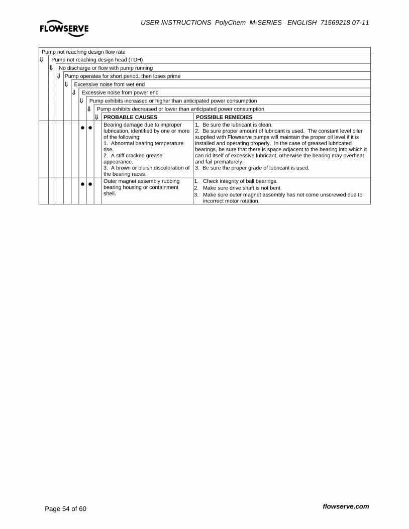
USER INSTRUCTIONS PolyChem M-SERIES ENGLISH 71569218 07-11
flowserve.com Page 54 of 60
®
Pump not reaching design flow rate
Pump not reaching design head (TDH)
No discharge or flow with pump running
Pump operates for short period, then loses prime
Excessive noise from wet end
Excessive noise from power end
Pump exhibits increased or higher than anticipated power consumption
Pump exhibits decreased or lower than anticipated power consumption
PROBABLE CAUSES POSSIBLE REMEDIES
Bearing damage due to improper lubrication, identified by one or more of the following: 1. Abnormal bearing temperature rise. 2. A stiff cracked grease appearance. 3. A brown or bluish discoloration of the bearing races.
1. Be sure the lubricant is clean. 2. Be sure proper amount of lubricant is used. The constant level oiler supplied with Flowserve pumps will maintain the proper oil level if it is installed and operating properly. In the case of greased lubricated bearings, be sure that there is space adjacent to the bearing into which it can rid itself of excessive lubricant, otherwise the bearing may overheat and fail prematurely. 3. Be sure the proper grade of lubricant is used.
Outer magnet assembly rubbing bearing housing or containment shell.
1. Check integrity of ball bearings.
2. Make sure drive shaft is not bent.
3. Make sure outer magnet assembly has not come unscrewed due to incorrect motor rotation.

USER INSTRUCTIONS PolyChem M-SERIES ENGLISH 71569218 07-11
flowserve.com Page 55 of 60
®
8 PARTS LIST AND DRAWINGS 8.1 PolyChem Group A and 1 Close Coupled
Drawing taken from CY61190-1
8.2 PolyChem Group A and 1 Long Coupled
Drawing taken from CY61191-0
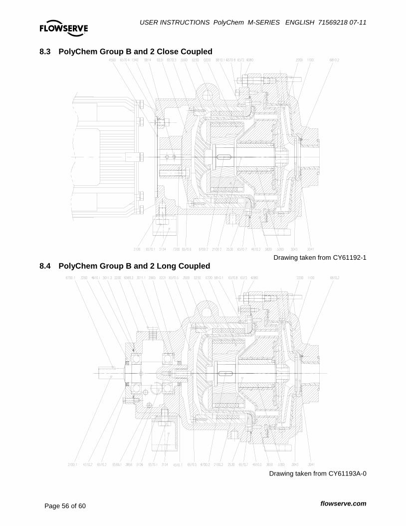
USER INSTRUCTIONS PolyChem M-SERIES ENGLISH 71569218 07-11
flowserve.com Page 56 of 60
®
8.3 PolyChem Group B and 2 Close Coupled
Drawing taken from CY61192-1
8.4 PolyChem Group B and 2 Long Coupled
Drawing taken from CY61193A-0

USER INSTRUCTIONS PolyChem M-SERIES ENGLISH 71569218 07-11
flowserve.com Page 57 of 60
®
8.5 PolyChem Group A and 1
Item Numbers Description
0220 Inner Magnet Assembly
0230 Outer Magnet Assembly
0231 Flange-Outer Magnet
1100 Casing
1340 Lantern
2100.1 Power End Shaft
2100.2 Pump Shaft
2200 Impeller
2905 Wave Spring Washer
3011.1 Power End Bearing-Inboard
3011.2 Power End Bearing-Outboard
3041 Thust Bearing-Casing
3043 Thrust Bearing-Impeller
3134 Bearing Housing Foot
3200 Bearing Housing
3260 Bearing Housing End Cover
3300 Bushing
3500 Containment Shell
3830 Bearing Holder
3853 Nipple *
3856 Constant level oiler Oiler *
3858 Oil Sight Glass
3891 Tag-Oil Level *
4310.1 Oil Seal-Inboard
4310.2 Oil Seal-Inboard
4590.1 Gasket-Lantern
4590.2 Gasket-Motor Flange/Motor
4610 0-Ring Bearing End Cover
6540 Motor Flange
6569.1 Plug-Brg Housing Drain
6569.2 Brg Housing Vent
6570.1 Screw-Bearing Housing Foot
6570.2 Screw-End Cover/Brg Housing
6570.3 Screw-Outer Magnet Flange
6570.4 Screw-Motor Flange/Motor
6570.5 Screw-Reverse Rotation
6570.6 Screw-Lantern/Bearing Housing
5670.9 Screw-Hub
6572 Casing Stud
6575 Jack screw *
6580 Casing Stud Nut
6700.1 Coupling Key
6700.2 Key-Pump Shaft
6810.1 Outer Magnet Rub Pins
6810.2 Anti Rotation Pin-Casing
6814 Set Screw-Motor Hub
* Not shown in the drawings
8.6 PolyChem Group B and 2
Item Numbers Description
0220 Inner Magnet Assembly
0230 Outer Magnet Assembly
0231 Flange-Outer Magnet
1100 Casing
1340 Lantern
2100.1 Power End Shaft
2100.2 Pump Shaft
2200 Impeller
2530 Retaining Ring-Shell
2905 Wave Spring Washer
3011.1 Power End Bearing-Inboard
3011.2 Power End Bearing-Outboard
3041 Thust Bearing-Casing
3043 Thrust Bearing-Impeller
3126 Shim
3134 Bearing Housing Foot
3200 Bearing Housing
3260 Bearing Housing End Cover
3300 Bushing
3500 Containment Shell
3830 Bearing Holder
3853 Grease nipple *
3856 Constant level oiler *
3858 Oil sight glass
3891 Tag-Oil Level *
4310.1 Oil Seal-Inboard
4310.2 Oil Seal-Inboard
4590 Gasket-Motor Flange/Motor
4610.1 0-Ring Bearing End Cover
4610.2 O-Ring Bearing Holder
6569.1 Plug-Brg Housing Drain
6569.2 Brg Housing Vent
6570.1 Screw-Bearing Housing Foot
6570.2 Screw-End Cover/Brg Housing
6570.3 Screw-Outer Magnet Flange
6570.4 Screw-Lantern/Motor
6570.5 Screw-Reverse Rotation
6570.7 Screw-Retaining Ring
6570.8 Screw-Lantern / Bearing holder
6570.9 Screw-Hub
6572 Casing Stud
6575 Jack screw *
6579.4 Screw-Motor Flange/Motor
6580 Casing Stud Nut
6700.1 Coupling Key
6700.2 Key-Pump Shaft
6810.1 Outer Magnet Rub Pins
6810.2 Anti Rotation Pin-Casing
6814 Set Screw-Motor Hub
7200 Motor Hub
USER INSTRUCTIONS PolyChem M-SERIES ENGLISH 71569218 07-11
flowserve.com Page 58 of 60
®
9 CERTIFICATION Certificates determined from the contract requirements are provided with these instructions where applicable. Examples are certificates for CE marking and ATEX marking etc. If required, copies of other certificates sent separately to the Purchaser should be obtained from Purchaser for retention with these User Instructions.
10 OTHER RELEVANT DOCUMENTATION AND MANUALS
10.1 Supplementary User Instructions Supplementary instructions such as for a driver, instrumentation, controller, seals, sealant systems etc are provided as separate documents in their original format. If further copies of these are required they should be obtained from the supplier for retention with these User Instructions.
10.2 Change notes If any changes, agreed with Flowserve Pump Division, are made to the product after it is supplied, a record of the details should be maintained with these User Instructions.
10.3 Additional sources of information The following are excellent sources for additional information on Flowserve PolyChem S-series pumps, and centrifugal pumps in general. Pump Engineering Manual R.E. Syska, J.R. Birk, Flowserve Corporation, Dayton, Ohio, 1980. Specification for Horizontal End Suction Centrifugal Pumps for Chemical Process, ASME B73.1M The American Society of Mechanical Engineers, New York, NY. End-suction centrifugal pumps (rating 16 bar) – Designation, nominal duty point and dimensions, ISO 2858 International Organization for Standardization American National Standard for Centrifugal Pumps for Nomenclature, Definitions, Design and Application (ANSI/HI 1.1-1.3) Hydraulic Institute, 9 Sylvan Way, Parsippany, New Jersey 07054-3802.
Technical specification for centrifugal pumps – Class II, ISO 5199 International Organization for Standardization American National Standard for Centrifugal Pumps for Installation, Operation, and Maintenance (ANSI/HI 1.4) Hydraulic Institute, 9 Sylvan Way, Parsippany, New Jersey 07054-3802. Flowserve Durco Pump Parts Catalog. Flowserve PolyChem Sales Bulletin. RESP73H Application of ASME B73.1M-1991, Specification for Horizontal End Suction Centrifugal Pumps for Chemical Process, Process Industries Practices Construction Industry Institute, The University of Texas at Austin, 3208 Red River Street, Suite 300, Austin, Texas 78705. Pump Handbook 2nd edition, Igor J. Karassik et al, McGraw-Hill, Inc., New York, NY, 1986. Centrifugal Pump Sourcebook John W. Dufour and William E. Nelson, McGraw-Hill, Inc., New York, NY, 1993. Pumping Manual, 9th edition T.C. Dickenson, Elsevier Advanced Technology, Kidlington, United Kingdom, 1995.

USER INSTRUCTIONS PolyChem M-SERIES ENGLISH 71569218 07-11
flowserve.com Page 59 of 60
®
Notes:
USER INSTRUCTIONS PolyChem M-SERIES ENGLISH 71569218 07-11
flowserve.com Page 60 of 60
®
Your Flowserve factory contact: Flowserve Pump Division 3900 Cook Boulevard Chesapeake, VA 23323-1626 USA Telephone +1 757 485 8000 Fax +1 757 485 8149 Flowserve Pumps Flowserve GB Limited Lowfield Works, Balderton Newark, Notts NG24 3BU United Kingdom Telephone (24 hours): +44 1636 494 600 Sales & Admin Fax: +44 1636 705 991 Repair & Service Fax: +44 1636 494 833 Email: [email protected]
Your local Flowserve representative: To find your local Flowserve representative please use the Sales Support Locator System found at www.flowserve.com
FLOWSERVE REGIONAL
SALES OFFICES:
USA and Canada
Flowserve Corporation
5215 North O’Connor Blvd.,
Suite 2300
Irving, Texas 75039-5421, USA
Telephone +1 972 443 6500
Fax +1 972 443 6800
Europe, Middle East, Africa
Flowserve FSG – Italy
Worthing S.P.A.
Via Rossini 90/92
20033 Desio (Milan), Italy
Telephone +39 0362 6121
Fax +39 0362 628 882
Latin America and Caribbean
Flowserve Corporation
6840 Wynnwood Lane
Houston, Texas 77008, USA
Telephone +1 713 803 4434
Fax +1 713 803 4497
Asia Pacific
Flowserve Pte. Ltd
10 Tuas Loop
Singapore 637345
Telephone +65 6771 0600
Fax +65 6862 2329