user manual abb i-bus eib / knx · user manual abb i-bus ... abb i-bus® eib / knx bus connection...
TRANSCRIPT

User Manual ABB i-bus® EIB / KNX
Application Unit AB/S 1.1
with the Application Logic Time
200 IO/1.4 for the ETS3
Intelligent Installation SystemsSK 9

This manual describes the function of the Application Unit AB/S 1.1 with the Application Logic Time 200 IO/1.4 for the ETS3.
Subject to changes and errors excepted.
Exclusion of liability:
Despite checking that the contents of this document and matching the hardware and software, deviations cannot be completely excluded. We therefore cannot accept any liability for this. Any necessary corrections will be inserted in new versions of the manual.
Please inform us of any errors or suggested improvements.
������������� ��
Overview ............................................................................................................... 1
System requirements ............................................................................................ 1
������������������������ ��!�������������������������"�� #�
Product description ............................................................................................... 2
The application unit AB/S 1.1 ................................................................... 2
Simple and clear graphical project design ............................................... 3
Graphical project design using function chart .......................................... 3
Working in a familiar software environment .............................................. 4
Technical data ........................................................................................... 5
$�%�����&��#''�����"(� ��������� )�
Overview ............................................................................................................... 6
Starting the application Logic Time 200 IO/1.4 ..................................................... 7
Assigning new elements ....................................................................................... 7
Linking functions ................................................................................................... 8
Displaying links ..................................................................................................... 10
Editing elements .................................................................................................... 10
Input and output objects ........................................................................................ 11
Edit object dialog.................................................................................................... 13
Input dialog ............................................................................................................ 16
Output dialog ......................................................................................................... 17
Linking input and output objects with group addresses ......................................... 18
Logical element ..................................................................................................... 19
Gate ...................................................................................................................... 21
Timer ..................................................................................................................... 23
Applikation unit AB/S 1.1 with the application logic time 200 IO/1.4 Page ii
Staircase function (autoreset) ................................................................................27
Plausibility (validity) checks ..................................................................................28
Printing .................................................................................................................29
Page settings ...........................................................................................29
Font .........................................................................................................29
Printer settings .........................................................................................29
Saving ....................................................................................................................29
Worksheet management ........................................................................................30
Toolbar ...................................................................................................................31
Menu bar ..............................................................................................................31
Project menu ...........................................................................................31
Edit menu ................................................................................................32
View menu ...............................................................................................33
Help menu ...............................................................................................34
Working in the workspace ......................................................................................35
Moving elements in the workspace .........................................................35
Selection of elements ..............................................................................35
Multiple selection of elements .................................................................35
Hotkey table ..........................................................................................................36
������ ������� *+�
The "event driven logic" of the AB/S1.1 ...................................................37
AND, OR, XOR logic functions ................................................................38
The gate ..................................................................................................38
The timer .................................................................................................40
Output of transient intermediate states (glitches) ....................................42
Feedback loops e.g. memory ..................................................................45
Reaction time ...........................................................................................45
Bus load ...................................................................................................46
Application unit AB/S 1.1 with the application logic time 200 IO/1.4 Page iii

Behaviour on bus voltage failure ................................................................46
Application tips ............................................................................................46
Technical hotline .........................................................................................46
Application unit AB/S 1.1 with the application logic time 200 IO/4.4 Page iv

�,��,��-�The application $�%�����&��#''�����"(�makes it possible to design and commission the logic functions
of the application unit AB/S 1.1 directly in ETS3.
The parameterisation is carried out in a graphic function chart. Here the logic functions, inputs, outputs and
links are applied and the parameters of the functions are edited. $�%�����&��#''�����"(�features the
following functions:
� 200 communication objects can be selected as inputs or outputs.
� 50 logical elements can be defined as AND, OR and EXCLUSIVE OR.
� 50 gates are regulated dependent on a control input and switch through various object values.
� 30 timers and staircase lighting functions can be set from 0 to 18 hours.
�.���&���/����&�����
The following system configuration is required for using $�%�����&��#''�����"(:
� System configuration in accordance with the ETS3 reference manual
� ETS3 V1.0
Application unit AB/S 1.1 with the application logic time 200 IO/1.4 Page 1

�!�������������������������"�� The application unit AB/S 1.1 is a modular installation device from the ABB i-bus EIB system. It is two
modules wide and is mounted in the distribution board. It is connected to the bus via bus connection
terminals at the front of the device.
Using the ETS3 program, the device can be loaded with applications which serve to automate
processes in buildings. A user-friendly, graphical interface integrated into the ETS3 for the
parameterisation of the application unit AB/S 1.1 with the application ������������� ������enables
fast and clear project design with complex logic functions and operations.
Application unit AB/S 1.1 with the application logic time 200 IO/1.4 Page 2

It enables basic logic elements to be positioned and linked with each other in a very simple manner.
Controllers, logic operations and time control can be implemented.
��&��������������%���!��������0��������%�� Parameters are assigned to the application ������������� ������in ETS3 simply and clearly with the aid
of an integrated graphical interface that is similar to a programmable logic controller (PLC). The
configured application can be provided with comments and printed out for documentation purposes.
The application features the following basic functions:
� 200 communication objects can be selected as inputs or outputs and allow up to 250 associations. The
object type can have different formats (from 1 bit to 2 bytes).
� 50 logical elements can be defined as AND, OR and EXCLUSIVE OR, each with up to 8 inputs and
one output. The inputs and outputs can be negated. Logic operations can be implemented using
these logical elements.
� 50 gates which are each regulated dependent on a control input and can switch through various object
values from 1 bit to 2 bytes; filter functions are likewise available. It is therefore possible for example to
design partition functions.
� 30 timers and staircase lighting functions that can be set from 0 to 18 hours are available for ON or
OFF delays. The staircase lighting functions are configured automatically and are therefore very easy
to use.
With these basic elements, it is possible to implement logic control, logic operations, interlocks, fault
signals, telegram multiplication and a range of further functions which are required in daily practice.
Further applications such as memory or sequence control can also be implemented using a combination of
logical elements.
1���!��������0��������%������%� ���������!���� The graphical user environment for the parameterisation of the AB/S 1.1 uses various basic
functions and interfaces of ETS3. It is integrated directly into ETS3 and can therefore be operated in
the usual ETS3 environment.
The design of the logic functions is carried out in the Project Design module of ETS3 and
implemented in a graphic function chart based on DIN 40900.
Application unit AB/S 1.1 with the application logic time 200 IO/1.4 Page 3

The graphic project design is started via the ETS3 device dialog. Here the logic functions, inputs,
outputs and the links are assigned via “Drag & drop” and the parameters are set.
All the data can be printed out in graphic and list form and is stored in the ETS3 database. Data exchange
is thus carried out automatically during ETS3 project export and import.
2��3��%������ �&�������� �-������,����&���� The configuration and commissioning of the application unit AB/S 1.1 with logical functions is simple and
intelligible for the user as no additional software package needs to be installed, learned or operated.
The project design and commissioning takes place directly in the familiar environment and working
method of ETS3. The installation of the software tool is carried out automatically when loading the ETS3
product data from ABB STOTZ-KONTAKT.
Application unit AB/S 1.1 with the application logic time 200 IO/1.4 Page 4

���!�����������
Power supply 24 V DC, via ABB i-bus® EIB / KNX
Operating and display elements
LED (red) and push button For assignment of the physical address
Type of protection IP 20 conform to DIN 40 050
Safety class I I
Operating temperature range -5...+45 °C
Connection
ABB i-bus® EIB / KNX Bus connection terminal (included with supply)
Installation On 35 mm mounting rail, DIN EN 50 022
Dimensions 90 x 36 x 64 mm (H x W x D)
Mounting depth/width 68 mm / 2 modules at 18 mm
Weight 0.100 kg
Application unit AB/S 1.1 with the application logic time 200 IO/1.4 Page 5

The configuration of the logic functions of the application $�%�����&��#''�����"(�is carried out directly in
ETS3. When the parameterisation option is selected in the ETS3 the graphic configuration module is
started in the background. The ETS3 device dialog is displayed again after exiting the graphic
configuration module.
The main window of the application $�%�����&��#''�����"(�consists of the
� menu bar,
� toolbar and
� a workspace for designing the logic control
There is an integrated context-sensitive Help menu which can be called up at any time.
Application unit AB/S 1.1 with the application logic time 200 IO/1.4 Page 6

The graphic configuration module is started from the �������%�4��- window.
The application Logic Time 200 IO/1.4 is accessed by pressing the right mouse button on the device line and
selecting 5���&�����""" in the pop-up menu. Double-clicking on the device and subsequent clicking on
5���&����� in the �����6�,����menu will also access the application Logic Time 200 IO/1.4.
New elements such as inputs, outputs, logic functions and links can be assigned using the toolbar. The
relevant element is selected in the toolbar and placed in the workspace. Several elements of the selected
type can be added if the 7��� key is pressed during insertion.
Application unit AB/S 1.1 with the application logic time 200 IO/1.4 Page 7

A grid can be inserted from the 4��- menu in order to align the elements automatically.
Assigned elements can be deleted. Any associated links to the element are also automatically deleted.
$��3��%� ���������A link can be assigned by clicking on an input or output object and the input or output of a function.
The starting point of the link is selected with the right mouse button, keeping the mouse button pressed
down, the mouse pointer is then dragged until it reaches the end of the required link and the mouse button is
then released.
Application unit AB/S 1.1 with the application logic time 200 IO/1.4 Page 8
Links are shown as lines. Crossover points are not drawn. If another line has to be crossed to
represent a link, this is indicated by an auxiliary flag. The labelling of the flag is assigned automatically
and cannot be changed.
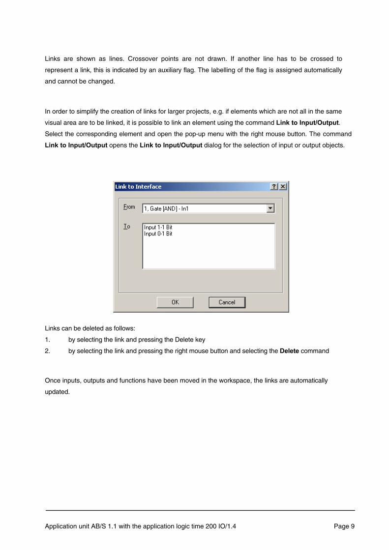
In order to simplify the creation of links for larger projects, e.g. if elements which are not all in the same
visual area are to be linked, it is possible to link an element using the command $��3����������������.
Select the corresponding element and open the pop-up menu with the right mouse button. The command
$��3���������������� opens the $��3���������������� dialog for the selection of input or output objects.
Links can be deleted as follows:
1. by selecting the link and pressing the Delete key
2. by selecting the link and pressing the right mouse button and selecting the 6����� command
Once inputs, outputs and functions have been moved in the workspace, the links are automatically
updated.
Application unit AB/S 1.1 with the application logic time 200 IO/1.4 Page 9

The associated links of an element can be displayed via the dialog $��3���-��!. Select the relevant
element and open the pop-up menu with the right mouse button. The command $��3���-��! opens
a dialog box and displays the links that have been configured.
The parameters of the elements can be edited in detail dialogs. These are opened
� by double-clicking on the relevant element,
� via the pop-up menu (right mouse button)
Function inputs and outputs are negated by a mouse click. The display of the element is changed
accordingly.
Application unit AB/S 1.1 with the application logic time 200 IO/1.4 Page 10

These correspond to the communication objects of ETS3. They are therefore also visible in the ETS3 windows and can likewise be edited there. The general communication object properties are set via the 5���&�����"""� pop-up menu. Inputs and outputs have different parameters.
Input Output
No., Type
Group addresses
No., Type
Group addresses
Application unit AB/S 1.1 with the application logic time 200 IO/1.4 Page 11
No.: <Input|Output><Object no.> Type: 1, 4, 8, 16 bit
Logical elements can be added and edited via the New, Delete and Negate buttons.

The following parameters can be modified via the 5���&�����""" Input dialog.
� Object type
� Behaviour on bus voltage recovery without loss of data
� Behaviour on bus voltage recovery with loss of data
The following parameters can be modified via the 5���&�����""" Output dialog.
� Object type
� Send criteria
Depending on the type of connection, i.e. which function an input or output is linked with, the size of the
communication object can be selected as 1, 4, 8 or 16 bit.
�����8� In the event of a bus voltage failure, the values of the input objects are stored for at
least an hour. Should the bus voltage failure last longer than an hour, the values could be lost but still be preserved. A check is therefore made in the AB/S 1.1 on bus voltage recovery before processing the values of the input objects to see whether data loss has occurred in the meantime.
Application unit AB/S 1.1 with the application logic time 200 IO/1.4 Page 12
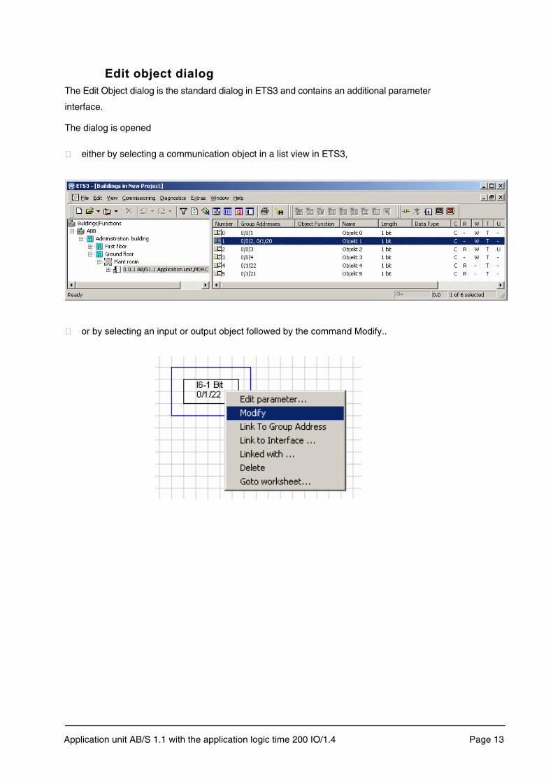
������ 0���������%�The Edit Object dialog is the standard dialog in ETS3 and contains an additional parameter
interface.
The dialog is opened
� either by selecting a communication object in a list view in ETS3,
� or by selecting an input or output object followed by the command Modify..
Application unit AB/S 1.1 with the application logic time 200 IO/1.4 Page 13

Apart from selecting the usual communication object data, it is also possible to set the input and
output object parameters and the size of the communication object by clicking on the 5���&����
option.
The 5������. can be selected from the options in the drop-down list in the right upper hand corner and set
to the following values:
� Auto: Lower priority for uncritical time functions
� Normal: Normal priority for manual functions
� Alarm: High priority for critical time functions
To set the communication object flag, make the required selection in the corresponding
checkboxes.
Application unit AB/S 1.1 with the application logic time 200 IO/1.4 Page 14
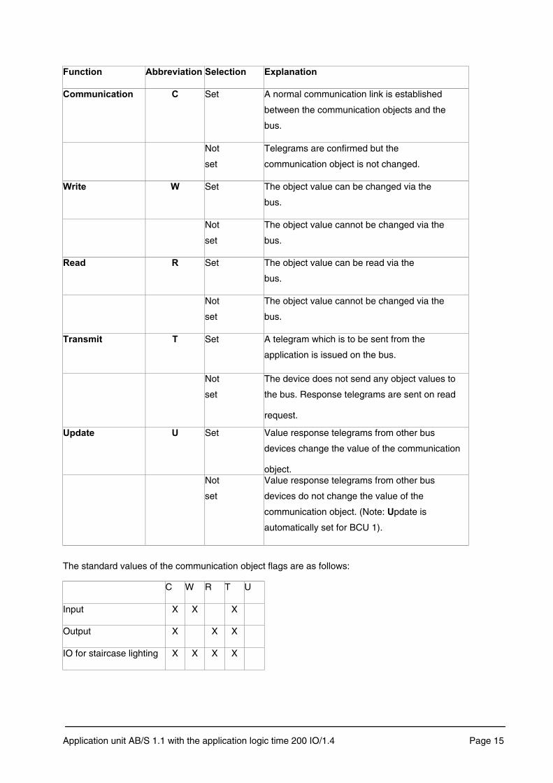
��������� � ��,����������������� �9����������
7�&&���������� 7� Set A normal communication link is established
between the communication objects and the
bus.
Not
set
Telegrams are confirmed but the
communication object is not changed.
2����� 2� Set The object value can be changed via the
bus.
Not
set
The object value cannot be changed via the
bus.
:���� :� Set The object value can be read via the
bus.
Not
set
The object value cannot be changed via the
bus.
�����&��� �� Set A telegram which is to be sent from the
application is issued on the bus.
Not
set
The device does not send any object values to
the bus. Response telegrams are sent on read
request.
;������ ;� Set Value response telegrams from other bus
devices change the value of the communication
object. Not
set
Value response telegrams from other bus
devices do not change the value of the
communication object. (Note: ;pdate is
automatically set for BCU 1).
The standard values of the communication object flags are as follows:
C W R T U
Input X X X
Output X X X
IO for staircase lighting X X X X
Application unit AB/S 1.1 with the application logic time 200 IO/1.4 Page 15

In order to mark a group address as a sending group address, select a group address in the ���� “Object
dialog” and click on the option ����������%. �
In order to delete an association between the group address and the communication object, select the
group address in the ���� “Object dialog” and click on the option 6�����������������. �
Clicking on the �������� option sets all the values to the values pre-selected by the manufacturer.
The parameters and type of a communication object can be determined by the user in the ����� dialog.
The dialog is opened via the 5���&���� option in the 7�&&����������� 0����dialog or by selecting an
input object and the 5���&���� command in the graphical parameter interface.
The following parameters can be modified in the ����� dialog.
� Object type
� Behaviour on bus voltage recovery without loss of data
� Preset value
� Behaviour on bus voltage recovery with loss of data
� Preset value
Depending on the type of connection, i.e. which function an input or output is linked with, the size of the
communication object can be selected as 1, 4, 8 or 16 bit.
Application unit AB/S 1.1 with the application logic time 200 IO/1.4 Page 16

����8� In the event of a bus voltage failure, the values of the input objects are stored for at least an hour. Should the bus voltage failure last longer than an hour, the values could be lost but still be preserved. A check is therefore made in the AB/S 1.1 on bus voltage recovery before processing the values of the input objects to see whether data loss has occurred in the meantime.
The parameters and type of a communication object can be determined by the user in the ������ dialog.
The dialog is opened via the 5���&���� option in the 7�&&����������� 0����dialog or by selecting an
output object and the 5���&���� command in the graphical parameter interface.
The following parameters can be modified in the Output dialog.
� Object type
� Send criteria
Depending on the type of connection, i.e. which function an input or output is linked with, the size of the
communication object can be selected as 1, 4, 8 or 16 bit.
�������������8�
������%�<�������������"""�������!������������<�
With this setting, the output sends a telegram each time a new object value is assigned.
A new object value is then always given to the output if a telegram was sent to an allocated input,
regardless of whether the object value has changed (e.g. from ' to �) or has remained the same.
It would then be the case that there is a disabled gate in the transmission path from an assigned
input, which has just been sent a telegram, to the output or there is a timer operation that has still
not elapsed. In this instance the output is not assigned a new object value.
Application unit AB/S 1.1 with the application logic time 200 IO/1.4 Page 17

If there is a feedback loop in the transmission path to an output e.g. two logical elements which form a
memory device, then the output is continually assigned a new object value due to this feedback. �!��
��������!�������������.�����������%��&�"�
������%�<�������������"""����.��������������<�
With this setting, the output only sends a telegram if the object value changes.
$��3��%������������������� 0�����-��!�%���������������The linking of input and output objects with group addresses is carried out using an extension of the
standard procedure in ETS3. Links can be assigned in the graphical parameter interface by selecting an
input or output object and then calling up the $��3����1�������������dialog.
In the dialog it is possible to assign new group addresses or to select already existing group addresses. The
selection of existing group addresses can be sorted according to $��� or ��������. If ��� is selected, all the
existing group addresses are available for selection.
After selection of links between input and output objects with the right mouse button the
assigned group addresses can be deleted in the ������ 0��� dialog.
Application unit AB/S 1.1 with the application logic time 200 IO/1.4 Page 18

A logical element has up to 8 inputs and one output. When a new logical element is created, it has two
inputs.
The following can be edited in the $�%��������&����dialog:
� the number of the logical element
� its logical element name (36 characters)
� the logical element type (AND, OR, XOR)
� the number of inputs
� the negation of the inputs (the inputs must be linked)
� the negation of the outputs (the outputs must be linked)
The negation of a linked input or output can be set or deleted directly in the graphical user environment by
a double click with the left mouse button on the respective input/output. If the number of inputs is reduced,
only those inputs that have no associations are deleted. If inputs are added, the previous associations are
preserved.
Only 1 bit objects are permitted for the inputs/outputs of the logical elements.
Type: ≥1 (OR) & (AND) =1 (Exklusive OR) Negation
Application unit AB/S 1.1 with the application logic time 200 IO/1.4 Page 19

The inputs of a logical element can each be linked with an input or output object, i.e. a communication
object or an output of another function. The output of a logical element can be linked with an output
object or an input of another function. An output of a logical element can thus be linked with various
inputs of logical elements.
The following types of logical element are available:
Application unit AB/S 1.1 with the application logic time 200 IO/1.4 Page 20
AND OR Exklusive OR (XOR)
& A
B y ≥1
A
B
y =1 A
B
y
A
B
y
A B
y
A
B
y
A B y 0 0 0 0 1 0 1 0 0 1 1 1
A B y 0 0 0 0 1 1 1 0 1 1 1 1
A B y 0 0 0 0 1 1 1 0 1 1 1 0

1����
E Input S Save input signal - Do not save input signal F0 Filter (object values 0 are filtered i.e. not passed through) F1 Filter (object values 1 are filtered i.e. not passed through) - No filter Negation S Control input specific to input
A gate has one input, one output and a control input as well as a filter and a save function for the input. If
an event occurs at the input and the gate is enabled, it can transfer the value at the input to the output. If
the gate is disabled, there is no reaction.
The following parameters can be set via the 1��� dialog:
� the number of the gate
� the name of the gate (36 characters)
� the negation of the output
� the filter function
� the save function
Application unit AB/S 1.1 with the application logic time 200 IO/1.4 Page 21

The following rules apply when assigning parameters:
� All object types are permitted for the input and output.
� The object types of the input and output must be identical.
� If the output is assigned to a 1 bit object, the output can be negated.
� The input can be linked with an input or output object to an output of another function.
� The output can be linked with an output object or to an input of another function.
� Only 1 bit objects are permitted for the control input.
� The control input can be linked with an input object or with an output of another function.
� The filter can only be activated if the input is assigned to a 1 bit object.
� The filter function affects the input.
� The save function determines whether input signals should be saved when the gate is closed.
The following applies for the filter:
F0 = Input signals with the value 0 are filtered out i.e. not passed through
F1 = Input signals with the value 1 are filtered out i.e. not passed through
����8� With the parameter ��,����������%���, the last stored input signal is shown at the output when the control input is enabled. If the 6��������,� input signal is selected, there is no reaction.
Application unit AB/S 1.1 with the application logic time 200 IO/1.4 Page 22
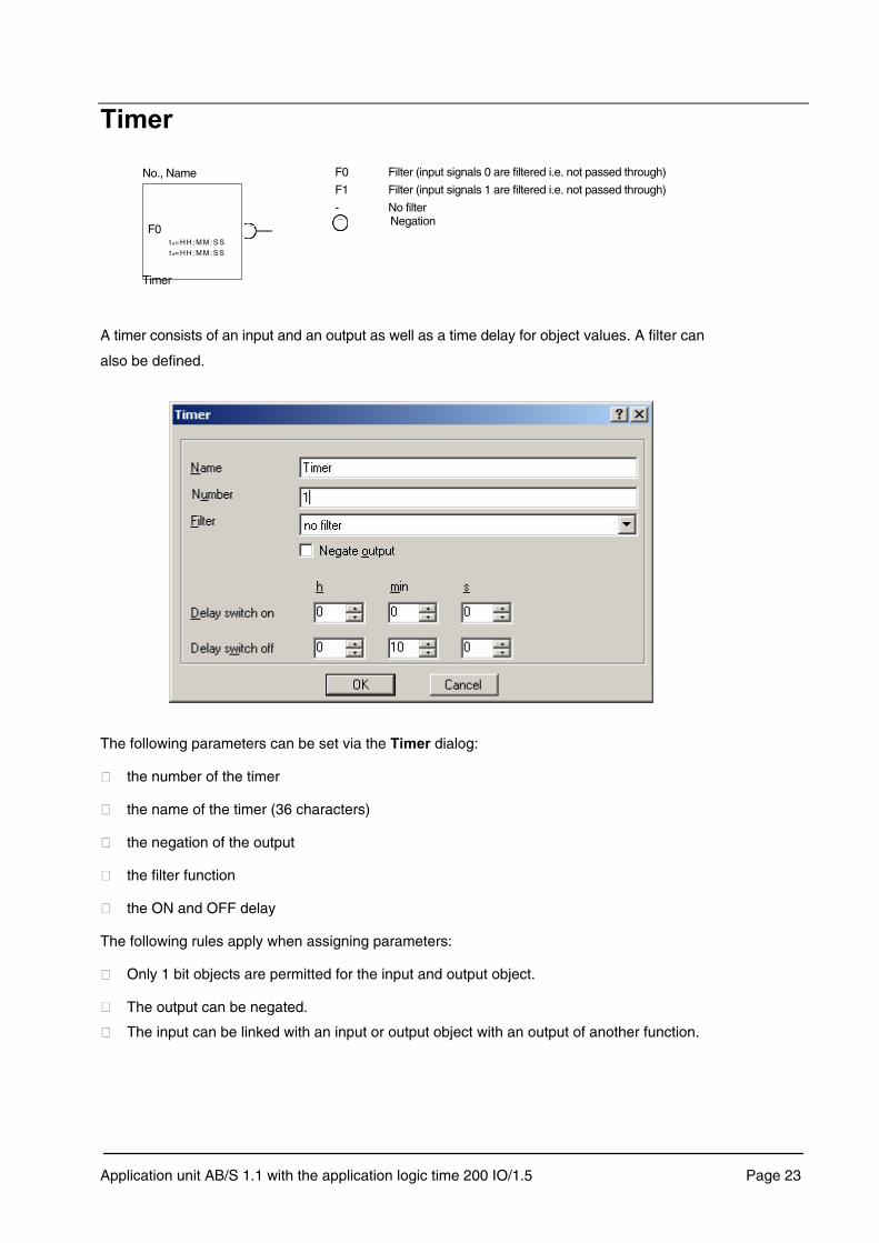
No., Name
F0 t e= H H: M M :S S t a= H H: M M :S S
Timer
F0 Filter (input signals 0 are filtered i.e. not passed through)
F1 Filter (input signals 1 are filtered i.e. not passed through)
- No filter Negation
A timer consists of an input and an output as well as a time delay for object values. A filter can
also be defined.
The following parameters can be set via the ��&�� dialog:
� the number of the timer
� the name of the timer (36 characters)
� the negation of the output
� the filter function
� the ON and OFF delay
The following rules apply when assigning parameters:
� Only 1 bit objects are permitted for the input and output object.
� The output can be negated.
� The input can be linked with an input or output object with an output of another function.
Application unit AB/S 1.1 with the application logic time 200 IO/1.5 Page 23

� The output can be linked with an output object and with an input of another function.
� The filter function affects the input.
� The time delay can be set between 0 and 18 hours 12 minutes and 15 seconds.
The following applies for the filter:
F0 = Input signals with the value 0 are filtered out i.e. not passed through
F1 = Input signals with the value 1 are filtered out i.e. not passed through
�!�� ����-��%���&�� ������������� ���&���&�����8�
�������.8�
An input signal of a longer duration appears at the output with an interval defined by the ON delay (te).
�
Application unit AB/S 1.1 with the application logic time 200 IO/1.4 Page 24

��������.8�
After the removal of the input signal, the output remains “1” for the duration of the OFF delay (ta)
Mode of operation for AB/S
Application unit AB/S 1.1 with the application logic time 200 IO/1.4 Page 25

���������������.8�
The output signal becomes “1” after the ON delay te “1” and remains in this state after the input signal
has been removed for the duration of the OFF delay ta.
Mode of operation for AB/S
Telegrams at
the input
Telegrams at
the output
����8� �In the event of bus voltage recovery after a bus voltage failure, the timers return to their initial state.
Application unit AB/S 1.1 with the application logic time 200 IO/1.4 Page 26
E
A
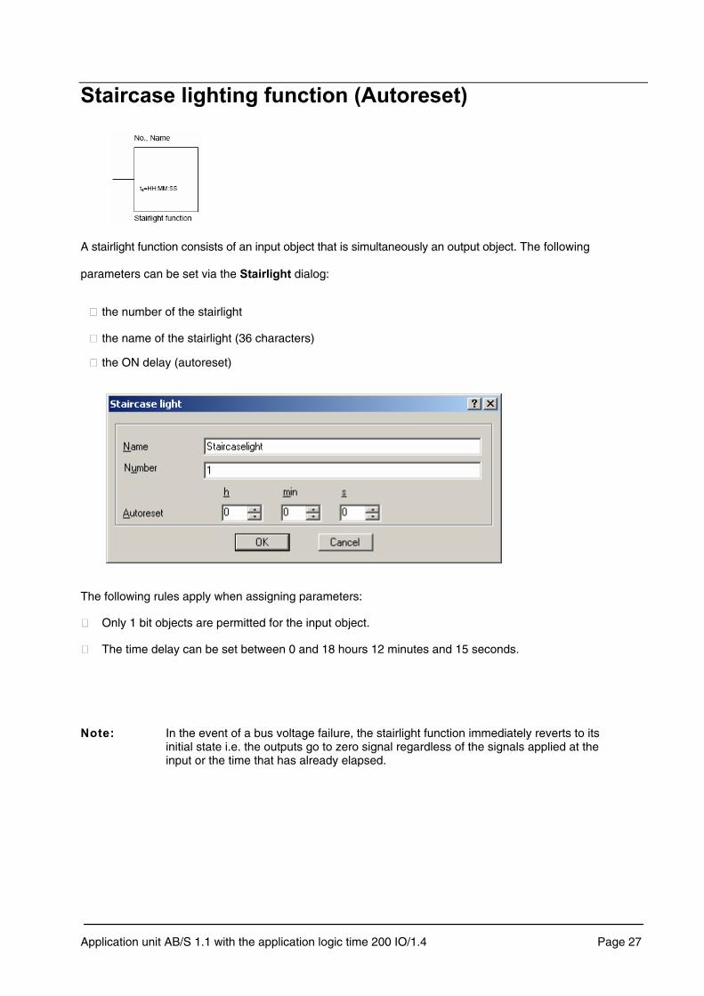
A stairlight function consists of an input object that is simultaneously an output object. The following
parameters can be set via the �������%!� dialog:
� the number of the stairlight
� the name of the stairlight (36 characters)
� the ON delay (autoreset)
The following rules apply when assigning parameters:
� Only 1 bit objects are permitted for the input object.
� The time delay can be set between 0 and 18 hours 12 minutes and 15 seconds.
����8� In the event of a bus voltage failure, the stairlight function immediately reverts to its initial state i.e. the outputs go to zero signal regardless of the signals applied at the input or the time that has already elapsed.
Application unit AB/S 1.1 with the application logic time 200 IO/1.4 Page 27
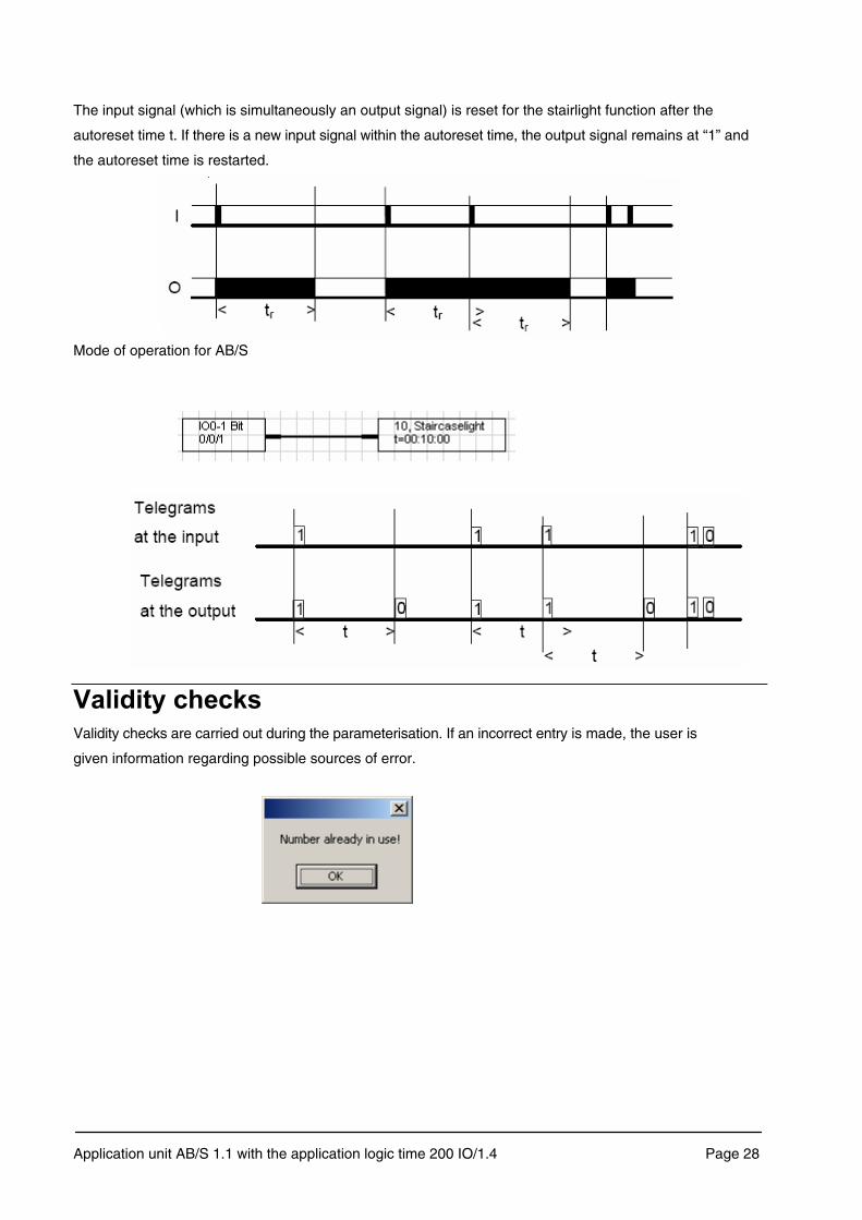
The input signal (which is simultaneously an output signal) is reset for the stairlight function after the
autoreset time t. If there is a new input signal within the autoreset time, the output signal remains at “1” and
the autoreset time is restarted.
Mode of operation for AB/S
Validity checks are carried out during the parameterisation. If an incorrect entry is made, the user is
given information regarding possible sources of error.
Application unit AB/S 1.1 with the application logic time 200 IO/1.4 Page 28

5�����The parameterisation can be printed out in graphical or list form. It is also possible to have a print
preview of both views via the menu command 5�����5��,��-. The ETS3 standard title page can be
printed out as a title page for the list view. This contains the properties and statistics of the project. The
header contains the device names as well as their physical addresses. The footer contains the page
number, the current date and time. It is possible to print all the pages, specific pages or user-defined
worksheets.
5�%��������%��
The layout of the printed page can be set using the 5�%������� dialog.
�����
The font for the printout can be selected in the ���� dialog.
5�������������%��
The printer, page orientation and paper can be selected in the standard MS Windows 5���� setup dialog.
��,��All the parameterisation data forms a part of the ETS3 project and is stored in the ETS3 database.
The parameterisation can be stored temporarily by pressing button ��,� in the toolbar.
Application unit AB/S 1.1 with the application logic time 200 IO/1.4 Page 29

When exiting the application you are asked to confirm whether you wish the parameterisation to be saved.
Additionally the � button in the �����6�,��� window should be pressed.
The graphical parameter interface can quickly become confusing the more complex the parameterisation
becomes and the lower the hardware requirements are for screen size and resolution. Worksheet
management is used in order to avoid this.
A worksheet is a text field. It describes a part of the graphical parameterisation and is implemented in the
form of jump labels. The graphical interface contains up to 200 worksheets. Worksheets can be applied,
edited and deleted.
The following can be defined
� the name (36 characters)
� the number
� the position
A worksheet can be selected using the menu. The selected worksheet is then placed in the visible area of
the screen.
Application unit AB/S 1.1 with the application logic time 200 IO/1.4 Page 30

The toolbar contains frequently used functions. All the functions of the toolbar can also be accessed via corresponding menus and are described there in more detail.
1. Saves the data in the ETS3 database
2. ;���8�Returns to the state before the last action was carried out
3. :���8�Deletes the last action
4. Delete the selected element or link
5. Deletes the entire content of the worksheet
6. =���8�Opens the online Help system.
7. �9��8�Closes the application Logic Time 200 IO/1.4 and returns to the ETS3
8. �:8�Inserts an OR logical element in the workspace.
9. ��68�Inserts an AND logical element in the workspace.
10. ��:8�Inserts an EXCLUSIVE OR logical element in the workspace.
11. 1���8�Inserts a gate function in the workspace.
12. ��&��8�Inserts a timer function in the workspace.
13. �$�%!�8�Inserts a stairlight function in the workspace.
14. �������������8�Inserts an input/output in the workspace.
15. 2�!���8�Inserts a new worksheet (text field) in the workspace.
Depending on the selected entry, further functions are available here.
5��0����&����
Application unit AB/S 1.1 with the application logic time 200 IO/1.4 Page 31
1 2 3 4 5 6 7
8 9 10 11 12 13 14 15
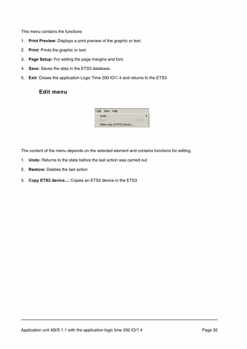
This menu contains the functions
1. 5�����5��,��-8�Displays a print preview of the graphic or text.
2. 5����8�Prints the graphic or text.
3. 5�%�������8�For setting the page margins and font.
4. ��,�8�Saves the data in the ETS3 database.
5. �9��8�Closes the application Logic Time 200 IO/1.4 and returns to the ETS3
�����&����
The content of the menu depends on the selected element and contains functions for editing.
1. ;���8�Returns to the state before the last action was carried out
2. :������8�Deletes the last action
3. 7��.����#���,���"""8�Copies an ETS2 device in the ETS3
Application unit AB/S 1.1 with the application logic time 200 IO/1.4 Page 32

�
4��-�&����
It is possible to select here whether the status and toolbar are displayed.
1���8 Switches the grid on or off
���-��3�!���"""8�Opens a dialog for selection of the worksheet.
The elements can be snapped into an exact position via the Grid command.
Application unit AB/S 1.1 with the application logic time 200 IO/1.4 Page 33

=����&����
The product-specific Help topics and the Info dialog can be displayed in this menu.
The Help menu can also be called up while a dialog is open: in this case it is context-sensitive and displays
the information necessary for carrying out the editing step.
Application unit AB/S 1.1 with the application logic time 200 IO/1.4 Page 34

>�,��%����&���������!��-��3������The visible area of the workspace can be moved using the scrollbars on the right hand side and at the
bottom of the screen. Elements can also be moved to a position outside the visible area. Select the
corresponding element with the right mouse button and move the mouse pointer in the required direction
keeping the mouse button pressed down. The visible area of the workspace moves if the scrollbars are
crossed over once or crossed over several times. If necessary the workspace is enlarged.
����������� ����&�����An element can be selected, e.g. to move or delete it. This is done by clicking on the element with the right
mouse button. This is also the case when selecting a line of association.
>������������������� ����&�����Several elements can be selected at once, e.g. for moving or deleting. The elements are selected using the
mouse. Press the left mouse button and drag out a rectangle, keeping the mouse button pressed down. The
selected elements are then displayed in colour. If elements outside the visible range are to be included,
please press the cursor arrow keys on the keyboard while dragging the rectangle. The visible section of the
workspace is moved and further elements can be selected.
Application unit AB/S 1.1 with the application logic time 200 IO/1 Page 35
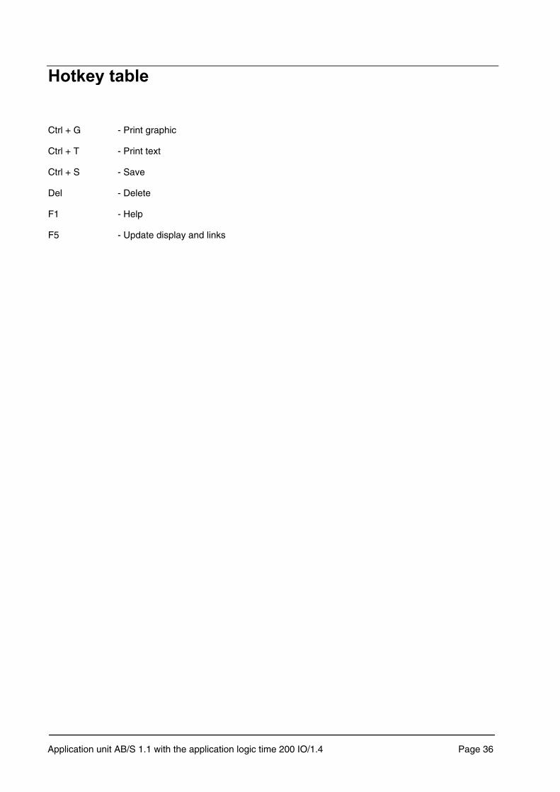
Ctrl + G - Print graphic
Ctrl + T - Print text
Ctrl + S - Save
Del - Delete
F1 - Help
F5 - Update display and links
Application unit AB/S 1.1 with the application logic time 200 IO/1.4 Page 36
�!��<�,�������,�����%��<�� ��!�������"��
Working with logic functions with EIB differs in several points from working with a programmable logic
controller (PLC) or a hard-wired programmed controller.
With a PLC or hard-wired controller, only a 1 signal or 0 signal can be applied statically at the input. With
EIB however it is possible that an input object already has the value 1 and another telegram with the value
1 is sent or that an input already has the value 0 and another telegram with the value 0 is sent.
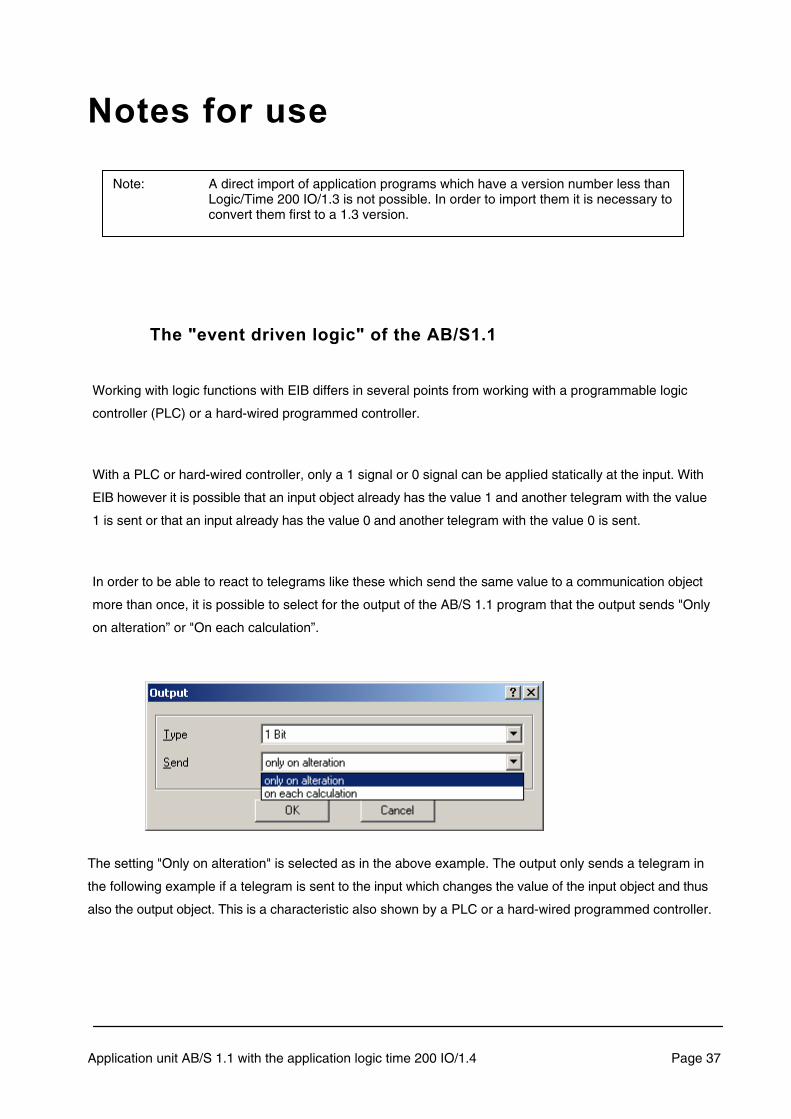
In order to be able to react to telegrams like these which send the same value to a communication object
more than once, it is possible to select for the output of the AB/S 1.1 program that the output sends "Only
on alteration” or "On each calculation”.
The setting "Only on alteration" is selected as in the above example. The output only sends a telegram in
the following example if a telegram is sent to the input which changes the value of the input object and thus
also the output object. This is a characteristic also shown by a PLC or a hard-wired programmed controller.
Application unit AB/S 1.1 with the application logic time 200 IO/1.4 Page 37
Note: A direct import of application programs which have a version number less than Logic/Time 200 IO/1.3 is not possible. In order to import them it is necessary to convert them first to a 1.3 version.

If however the setting "On each calculation" is selected then the output itself sends a telegram each time a
telegram is sent to the input i.e. even if there is no change in the value of the input object and therefore the
output. This is a characteristic which ABB i-bus EIB logic modules also display.
This characteristic, i.e. reacting not only to a signal change but also to repeated telegrams with the same
value, can be described in a wider sense by the term "event-driven logic".
��6?��:?���:���%��� ���������
There are no particular peripheral conditions to consider when using the "normal" logical functions such as
AND, OR or EXCLUSIVE OR.
The gate is one of the most important functional elements of event-driven logic.
If an event occurs at the input and the gate is enabled, it can transfer the value at the input to the output. If
the gate is disabled, there is no reaction.
Application unit AB/S 1.1 with the application logic time 200 IO/1.4 Page 38

If a gate is enabled, there are two possibilities depending on the parameters assigned:
1- If the parameter "Save input signal" is selected, the value at the input of the gate is transferred to the
output when the gate is enabled.
2- If the parameter "Do not save input signal" is selected, the value at the input of the gate is ����
transferred to the output when the gate is enabled. In this case an event must first occur at the input of
the gate, in order for the gate to transfer the value at the input to the output.
If however
� a gate is switched, which is not enabled, in a functional sequence between an
input and an output,
� or the output has been assigned parameters so that it also sends a
telegram each time a telegram is sent to an assigned input,
� or a telegram is sent to the input that is in front of the gate,
then the output does ��� send a telegram.
Application unit AB/S 1.1 with the application logic time 200 IO/1.4 Page 39

In the above example, both outputs have been assigned parameters so that they should send a telegram
on each assignment of a new object value.
If a telegram is now sent to inputs 0, 1, 2 with any value, then output 5 also sends each time. Output 4
however only sends a telegram if the gate has previously been enabled.
�!����&���
The timer has the same importance as the gate in "event-driven logic”.
In a functional sequence where the output is set to send a telegram on each calculation of a new value,
the timer behaves in the same way as a gate.
If therefore
� a timer is switched in a functional sequence between an input and an
output,
� or the output has been assigned parameters so that it also sends a
telegram each time a telegram is sent to an assigned input,
� or a telegram is sent to the input that is in front of the gate,
� or the timer operation has not yet elapsed,
then the output does ��� send a telegram.
Application unit AB/S 1.1 with the application logic time 200 IO/1.4 Page 40

A Timer operation that has not elapsed can be compared to a gate that is disabled.
In the above example the output only sends a telegram if the timer operation has elapsed.
The following should also be noted when using the existing timers in the AB/S 1.1 application:
If for example an ON delay is set at the timer and telegrams with the value "1" are sent to the assigned
input with a shorter interval than the delay time, then the beginning of the delay is restarted with each
new telegram i.e. the timer operation can never elapse.
������� ��������
The "filter function” is also only possible with event-driven logic.
On the filter you can set which telegram value is "filtered out", i.e. not passed through.
Application unit AB/S 1.1 with the application logic time 200 IO/1.4 Page 41

If a telegram which has been filtered out due to the settings arrives at the input of a gate, or a timer,
and the assigned output has been set so that it sends a telegram each time a new object value is
calculated, then the output does ��� send a telegram in this case.
An "effective" filter can thus also be compared with a disabled gate or a timer operation that has not
elapsed.
�������� ����������������&��������������@%����!��A�
Transient intermediate states are known to occur with hard-wired programmed controllers due to the internal
operating times of the logical elements.
These so-called %����!�� do not become apparent as they only last a few microseconds and normally all
memory devices and outputs have a delay of a few milliseconds.
Transient intermediate states can also occur with AB/S 1.1. This becomes noticeable for example
when several telegrams with different values are sent successively from a stable output state on the
bus until a stable output state is re-established.
These glitches become noticeable as usually the bus device that should react to these telegrams also
reacts.
7�������� ����!�������������� �%����!���
All logical connections should be analysed to see if glitches could occur due to different operating
(propagation) times of the logical elements.
The following should be noted:
If a signal change occurs at the input of a functional sequence, the current input state is then
determined for all the elements of the functional sequence and then set accordingly for the output.
This is carried out in sequential cycles.
�!�����������%�� ����&�����������.�����������������������!��������� ��!������& ����%"��!�������������
������������������������� ������ ����?� ����-��� .��!����%��������&����?�%�����������&���"�
Application unit AB/S 1.1 with the application logic time 200 IO/1.4 Page 42
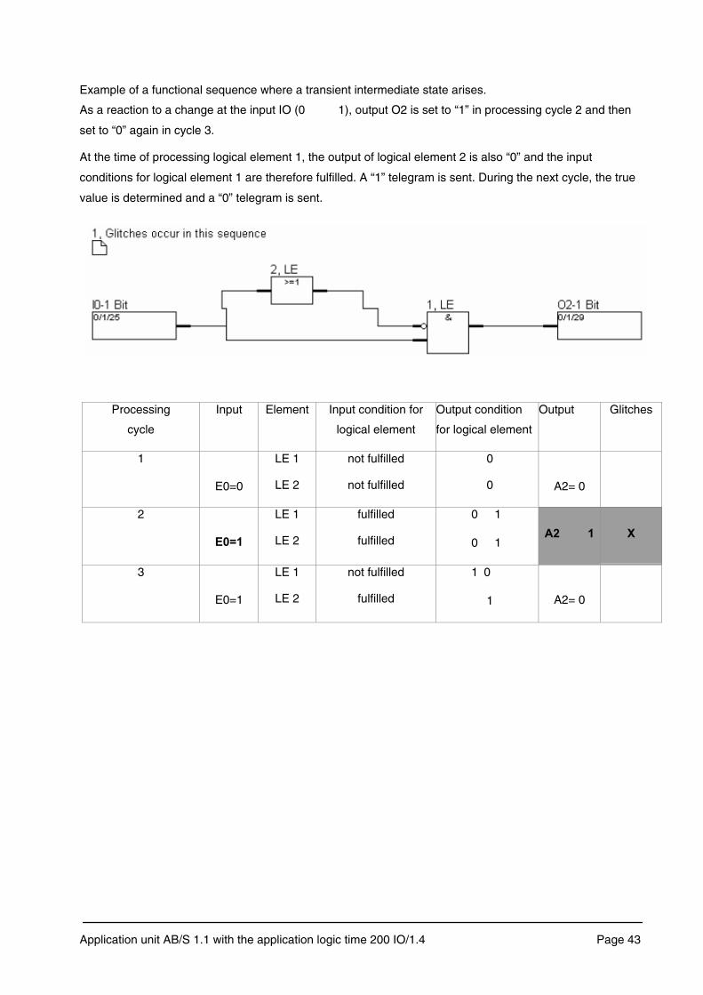
Example of a functional sequence where a transient intermediate state arises.
As a reaction to a change at the input IO (0 1), output O2 is set to “1” in processing cycle 2 and then
set to “0” again in cycle 3.
At the time of processing logical element 1, the output of logical element 2 is also “0” and the input
conditions for logical element 1 are therefore fulfilled. A “1” telegram is sent. During the next cycle, the true
value is determined and a “0” telegram is sent.
Processing
cycle
Input Element Input condition for
logical element
Output condition
for logical element
Output Glitches
1
E0=0
LE 1
LE 2
not fulfilled
not fulfilled
0
0 A2= 0
2
�'B��
LE 1
LE 2
fulfilled
fulfilled
0 1
0 1 �#� �� ��
3
E0=1
LE 1
LE 2
not fulfilled
fulfilled
1 0
1 A2= 0
Application unit AB/S 1.1 with the application logic time 200 IO/1.4 Page 43

Processing
cycle
Input Element Output condition for
logical element
Output condition
for output state
Output Glitches
1
E0=0
LE 1
LE 2
not fulfilled
not fulfilled
0
0 A2= 0
2
�'B��
LE 1
LE 2
fulfilled
not fulfilled
0 1
0 A2= 0
3
E0=1
LE 1
LE 2
not fulfilled
fulfilled
1 0
1 A2= 0
Example of a functional sequence where a transient intermediate state cannot arise. The output of logical
element 2 (also “1”) is first of all determined in processing cycle 2. The true value is determined in the same
cycle, output O2 remains “0”.
�� ����8�If the parameter is set to “Output sends … On each calculation”, there is a telegram at output 2
each time there is a telegram at input 0.
Application unit AB/S 1.1 with the application logic time 200 IO/1.4 Page 44

���� ��3��������"%"�&�&��.�
If feedback loops, e.g. for a memory device are implemented in an event-driven logic operation, it is not
possible to connect a timer in series.
Due to the feedback loops in the above example, the inputs constantly receive new values and thus
recalculate their status. These new calculations have the same effect on the timer as new telegrams. It
can therefore happen that the timer is not switched through.
It is also not possible for a functional sequence with feedback loops to connect an output in series if the
setting “Output sends …. On each calculation” is selected.
In this case the output would constantly send telegrams.
:����������&��The application Logic Time 200 IO/1.4 of the application unit AB/S 1.1 processes the logical
functions sequentially, similar to a PLC.
The state of the input and outputs is then determined in one processing cycle. Finally the elements are
processed internally according to the parameters that have been assigned.
The processing of elements in a cycle is carried out in the order of their numbering. The logical
elements are calculated first of all, followed by the gates and then the timers.
Finally the newly calculated states are sent.
The timer for a processing cycle – for processing the elements in ascending numerical order – is typically
100 ms.
Application unit AB/S 1.1 with the application logic time 200 IO/1.4 Page 45

���������If AB/S 1.1 with the application Logic Time 200 IO/1.4 is used as a telegram multiplier, a high bus load may
occur at times which should be considered during the configuration stage.
:����������� ���,����%�� �������
In the event of a bus voltage failure, the application unit AB/S 1.1 stores the states of the inputs and
outputs for at least an hour. If the bus voltage failure lasts considerably longer than an hour, the stored
states are lost.
States that are stored after a bus voltage failure can be accessed by selecting the parameter setting:
"Behaviour on bus voltage recovery”.
In order to avoid unwanted operational performance particularly in larger installations, the installation of an
uninterruptible power supply (UPS) should be provided for the bus voltage and for the interrogation voltage
of the contacts.
�����������������
� Use the application sensibly and within its limits
� Define and fix the task of the controller (e.g.: functional sequence, etc.)
� Structure and document the control system (use worksheets)
� Use logic functions sensibly and carefully
� Consider the chronological sequence and order of the signals
� Note the working method of AB/S 1.1 according to the manual or Help function
� Allow sufficient reserve for corrections and additions (10-20%)
���!������!�������Our ABB i-bus EIB / KNX hotline is at your disposal for any technical queries you may have regarding
the application unit. You can contact us at the following number Tel.: +49 (0) 6221 / 701 434
Application unit AB/S 1.1 with the application logic time 200 IO/1.4 Page 46

The information in this leaflet is subject to change without further notice. Pub
. No.
2C
DC
509
026
D02
01
Your EIB-Partner