user manual - digital combat simulator
TRANSCRIPT

[NS 430] DCS
BELSIMTEK 1
FPL
Navigation System NS 430
USER MANUAL

DCS [NS 430]
2 NS 430
Dear User,
we thank you for your purchase of the NS 430 simulator module!
The NS 430 is a powerful navigation tool that provides pilots with precise flight/navigational information and communications, as well as the means to plan and monitor the progress of their flight. The device is designed for the continuous calculation and display of the aircraft's geoposition and flight parameters on the device screen; display of the aircraft icon relative to the flight plan on the electronic map; assistance to the crew by means of data on ground-based radio navigation, motion variables on
runways and within aviation hubs available in the instrument's database, and other such relevant data.
The NS430 provides the following functions:
• Display of precise geopositional data, with an aircraft indicator on the moving map and a
coordinate display on the information page of the instrument;
• Quick setup for navigating to a selected destination from the current location;
• Creation, editing, selection and activation of flight plans;
• Creation of custom WPTs;
• Indication of flight parameters with a graphical representation of the aircraft's deviation from
the flightpath of the specified route;
• Creation of a three-dimensional flight profile to ensure accurate vertical navigation;
• Calculation of fuel consumption;
• Obtaining information on air traffic;
• Creation of reminders;
• Access to flight checklists;
• Setting up countdown, arrival and enroute timers;
• Obtaining statistical data on flightpath stages;
• Sunrise/sunset time estimation
• Tuning of radiofrequencies for radio communication and navigation for equipment compatible
with the instrument.
The instrument's database provides access to the following information: airports and their runways, VOR beacons, NDB beacons, intersections, controlled airspace and special use areas, airport radio frequencies, FSS and ARTCC, as well as the procedures for departures, arrivals and landings.

[NS 430] DCS
BELSIMTEK 3
Yours truly,
The NS 430 Development Team
Website: www.belsimtek.com
DCS: www.digitalcombatsimulator.com
©2017 Belsimtek
All trademarks and registered trademarks are the property of their respective owners.

DCS [NS 430]
4 NS 430
Table of Contents INSTRUMENT CONTROLS ............................................................................................................................. 7
LEFT SIDE ............................................................................................................................................................ 7
RIGHT SIDE ......................................................................................................................................................... 8
LOWER SECTION CONTROLS ................................................................................................................................... 9
INSTRUMENT OPERATION .......................................................................................................................... 12
STARTUP PROCEDURE ......................................................................................................................................... 12
SCREEN ...................................................................................................................................................... 14
LEFT SCREEN PANEL ............................................................................................................................................ 14
LOWER SCREEN PANEL ........................................................................................................................................ 14
SCREEN ALLOTMENT ............................................................................................................................................ 14
PAGES ........................................................................................................................................................ 17
NAV PAGES ...................................................................................................................................................... 17
NAVdef Page ............................................................................................................................................. 17
NAVmap page ........................................................................................................................................... 19
NAVterrain Page ....................................................................................................................................... 22
NAVcom page ........................................................................................................................................... 23
NAVpos page ............................................................................................................................................ 24
NAVsat page ............................................................................................................................................. 25
NAVvprof Page .......................................................................................................................................... 26
WPT PAGE GROUP ............................................................................................................................................ 28
WPTero Page ............................................................................................................................................ 29
WPTrunway .............................................................................................................................................. 30
WPTfreq .................................................................................................................................................... 32
WPTapr Page ............................................................................................................................................ 33
WPTarr Page ............................................................................................................................................. 34
WPTdep Page ............................................................................................................................................ 35
WPTint Page ............................................................................................................................................. 36
WPTndb Page............................................................................................................................................ 37

[NS 430] DCS
BELSIMTEK 5
WPTvor Page ............................................................................................................................................ 38
WPTuser Page .......................................................................................................................................... 39
AUX PAGE GROUP ............................................................................................................................................ 42
AUXfpl Page ............................................................................................................................................. 42
AUXutil page ............................................................................................................................................ 44
AUXsetup1 Page ....................................................................................................................................... 45
AUXsetup2 page ....................................................................................................................................... 47
NRST PAGE GROUP ........................................................................................................................................... 48
NRSTapt Page .......................................................................................................................................... 49
NRSTint Page ............................................................................................................................................ 50
NRSTndb Page .......................................................................................................................................... 51
NRSTvor Page ........................................................................................................................................... 52
NRSTuser Page ......................................................................................................................................... 53
NRSTartcc Page ........................................................................................................................................ 54
NRSTfss Page ............................................................................................................................................ 55
NRSTspace Page ....................................................................................................................................... 56
FPL PAGE GROUP .............................................................................................................................................. 57
FPLact Page .............................................................................................................................................. 57
FPLcat Page .............................................................................................................................................. 59
DRCT Page ................................................................................................................................................ 62
PROC Page ............................................................................................................................................... 64
DEVELOPERS .............................................................................................................................................. 85
BELSIMTEK .................................................................................................................................................... 85
MANAGEMENT ........................................................................................................................................ 85
PROGRAMMERS ....................................................................................................................................... 85
DESIGN AND AUDIO ................................................................................................................................. 85
QUALITY CONTROL ................................................................................................................................... 86
Testers ...................................................................................................................................................... 86

DCS [NS 430]
6 GNS430
INSTRUMENT CONTROLS

[NS 430] DCS
BELSIMTEK 7
INSTRUMENT CONTROLS
Left Side
Figure 1: Left side controls
1. COM power/volume knob
2. VLOC volume knob
3. Large left knob
4. Small left knob
5. COM flip-flop
6. VLOC flip-flop
The COM power/volume knob regulates the unit’s energy consumption as well as the volume of radio communications. The VLOC volume knob regulates the volume of the selected VOR frequency (course beacons.) The large left knob is used to tune the megahertz frequency for the communications transciever (COM) or the VLOC receiver, depending on which is currently selected by the cursor. The small left knob is used to tune the kilohertz (kHz) value of the COM or VLOC, again depending on which is selected by the cursor. Press the knob in order to toggle the cursor between the COM and VLOC windows. The COM flip-flop button is used in order to change the active and reserve frequencies of COM. Press and hold this button to switch to the emergency channel (121.500 MHz.) The VLOC flip-flop button is used to change the active and reserve frequencies of VLOC. (i.e. activate the set reserve frequency.)

DCS [NS 430]
8 BELSIMTEK
Right Side
Figure 2: Right side controls
1. Range (RNG)
2. Direct
3. Menu (MENU)
4. Clear (CLR)
5. Enter (ENT)
6. Large right knob
7. Small right knob
The range (RNG) button allows the user to change the map scale. Press the upwards arrow in order to zoom out, and the downwards arrow to zoom in. The direct-to button allows the user to enter a destination waypoint, and shows a direct course to the chosen location. The menu (MENU) button brings up a context-sensitive list of options which allows the user to set or make changes to certain parameters and access additional functions. The clear (CLR) button is used to delete information or clear set options. Press and hold the button to immediately bring up the NAVDef screen. The enter (ENT) button is used to confirm an operation or enter data. It is also used to confirm information upon startup. The large right knob is used to choose between page groups (NAV, WPT, AUX, NRST.) It is also used to control the on-screen cursor. The small right knob is used to choose between pages under the selected page group (listed above.) Press this knob to bring up the on-screen cursor. The cursor allows the user to enter data and/or make selections a list of options.

[NS 430] DCS
BELSIMTEK 9
Lower Section Controls
Figure 3: Lower section controls
1. CDI
2. OBS
3. MSG
4. FPL
5. PROC

DCS [NS 430]
10 BELSIMTEK
The CDI button is used to toggle between the navigational sources (GPS or VLOC) which provide output to the external indicators of the horizontal situation indicator (HSI) or the course deviation indicator (CDI.) This mode is maintained inside the instrument, and external subsystems may use it.
The (OBS) button is used in order to activate Suspended mode. Suspended mode is necessary in order to select the manual or automatic succession for the given set of waypoints. Pressing this button activates SUSP, which saves the current waypoint as “active” even after it is passed, suspending automatic transition to the next waypoint. Pressing the OBS button again returns the system to normal
operation with automatic sequencing of waypoints.
The MSG button is used to view system messages, important warning signs and prompts.
The FPL button allows for the creation, editing, activation and inversion of flight plans. It also provides access to landing approaches, departures, and arrivals.
The PROC button allows the pilot to select landing approaches, departures and arrivals from the active flight plan. When using a flight plan, available procedures from the departure and/or arrival airport are offered automatically. The pilot may also manually choose their airport and procedures if necessary.

[NS 430] DCS
BELSIMTEK 11
Instrument Operations

DCS [NS 430]
12 BELSIMTEK
Instrument Operation
Startup Procedure Upon startup the device will perform a systems test and data loading. The user is shown multiple screens: on the first screen the user will have to press (or rotate) the power knob and will be prompted to to press ENT several times. Afterwards the satellite status will be displayed on the screen, and after some time, the device will automatically jump to the second page of the NAV section. The instrument
will then be ready for operation.
Figure 4: Startup Procedure

[NS 430] DCS
BELSIMTEK 13
Figure 5: Instrument Panel Self-Test

DCS [NS 430]
14 Screen
Screen
Left Screen Panel The backup and active COM and VLOC frequencies are displayed on the left panel of the screen. To switch between these blocks have to press the small left knob. To select the desired MHz use the large knob; to select the kHz frequency - use the smaller knob. For example, set "115" and "400" for the frequency of "115.400".
To switch between the active and standby frequency, use the C or V button respectively.
Below the frequency blocks are three fields with diagnostics:
• Data availability for the NAVter page - TER TST, TER N/A, TERRAIN, TER INHB и TER FAIL
• CDI/RAIM modes: Landing approach (APR), Destination point (TERM), En-route (ENR) • GPS integrity violation (currently it is assumed that the GPS is always integral and no
errors are present in the diagnostics)
Lower Screen Panel The device status is displayed on the lower section of the screen:
• Navigation source: GPS, VLOC. • Temporary suspension (SUSP) or empty space (for normal operation/automatic sequencing) • Illuminated message panel: Blinking MSG signal (new message) or blank space (no new
messages) • Illuminated page panel (NAV/WPT/AUX/NRST/FPL/MSG/PROC/DIRECTTO) – displays
section name and page by order
Screen allotment The device screen is divided into 3 parts: left side with the frequency display, bottom section displaying the current status of the device, and the right side which contains a large number of pages, grouped in blocks. Switching between blocks is carried out using the large right knob. Switching between pages in a block is done using the small right knob.

[NS 430] DCS
BELSIMTEK 15
The four main blocks are shown below.
NAV WPT AUX NRST
NAVdef WPTapt AUXfpl NRSTaero
NAVmap
WPTrunway AUXutil NRSTint
NAVterrain
WPTfreq AUXsetup1 NRSTndb
NAVcom
WPTapr AUXsetup2 NRSTvor
NAVpos
WPTarr NRSTuser
NAVsat
WPTdep NRSTartcc
NAVvprof WPTint NRSTfss
WPTndb NRSTspace
WPTvor
WPTuser
In addition to the main blocks is the additional FPL block, access to which is through pressing the FPL
button. Separate pages for DIRECTTO, MSG and PROC are also present in the system.

DCS [NS 430]
16 Screen
FPL
FPLact
FPLcat
DRCT PROC MSG
Exit from these blocks is carried out either at the end of any action, or by holding the CLR button for 2 seconds.
Each of the main pages has an options menu, allowing you to choose the configuration of the relevant
page of your choice. Bring up the options menu by pressing the MENU button.

[NS 430] DCS
BELSIMTEK 17
PAGES
NAV Pages The navigation page group consists of 6 pages. While viewing any navigation pages, turn the small right knob to select another page. You can be sure that such a selection procedure makes it very easy to toggle between the navigation page set as default and the map page - the two most frequently used pages. The other pages provide you with lists of frequencies for your flight plan; show your current position; indicate the current reception of satellites; and define settings for vertical navigation.
NAVdef Page
Figure 1: NAVdef Page
The first page is the NAVdef page, displayed as default. This page can be quickly selected from any page using the CLR button (hold for 2 seconds).
The NAVdef page shows a graphic display of the deviation from the desired course (CDI) shown at the top of the page. Unlike the angular limits used on mechanical indicators, the scale limit for this indicator is defined by the ends of the scale. By default, the scale will automatically be adjusted to the needed scope depending on the phase of flight: en-route, terminal area, or approach.

DCS [NS 430]
18 PAGES
The graphic CDI shows your position in the center of the display relative to the desired course (the moving course deviation needle). Similar to traditional mechanical indicators, when you have deviated from the desired course, simply steer towards the needle. The arrows TO / FROM in the center of the scale indicates whether you are moving to the waypoint (up arrow) or you are passing by (the down
arrow).
The active stage of the flight plan, or the direct-to destination when using the Direct-to Key, is displayed directly below the CDI. This automatically sequences to the next waypoint of the flight plan as each interim waypoint is reached. If no flight plan or direct-to destination has been selected, the field remains
blank.
At the bottom of the NAVdef page you will find six user-defined fields that indicate the data required during the flight. By default, these fields are: distance to destination (DIS), Direct Track (DTK), bearing to destination (BRG), ground speed (GS), ground track (TRK) and the estimated time en route (ETE). However, each of these fields can be defined according to your preference. The available options are
as follows:
• Bearing to destination (BRG) • Distance to destination (DIS) • Enroute safe altitude (ESA) • Estimated time en-route (ETE) • Minimum safe altitude (MSA) • Ground track (TRK) • Cross track error (XTK) • Course to steer (CTS) • Desired track (DTK) • Ground speed (GS) • Track angle error (TKE) • Vertical speed required (VSR)
If no flight plan or direct-to waypoint is specified, only speed, heading, altitude and minimum safe altitude may be displayed. All other data types will appear as blank lines until a destination point is
selected.
To select different values for each data field:
1. Begin with the NAVdef page and press the MENU button for the options menu. 2. A prompt will always show: ‘Change Fields?’. Press enter to select this option. 3. Use the large right knob to select the field you wish to modify. 4. Turn the smaller right knob to display the list of available items. Continue to turn the knob
to select the required parameter from the list. 5. Press ENT to select the required parameter and return to the NAVdef page.
6. Press the right knob to remove the cursor from the page.
You may also return the data field settings to factory defaults.
1. Begin with the NAVdef page and press the MENU button for the options menu. 2. Turn the large right knob to select the “Restore Defaults?” option and press ENT.

[NS 430] DCS
BELSIMTEK 19
NAVmap page
Figure 7: NAVmap page
The second navigation page is the map page that indicates your current position using an airplane
symbol to indicate the nearest airports, navigation aids, custom waypoints, roads and cities.
To set the map scale:
1. Press the upwards arrow on the RNG button to zoom out.
2. Press the downwards arrow on the RNG button to zoom in.
Another function of the map page is the ability to pan the map beyond its current borders without setting the map scale. Clicking on the smaller right knob will show a target indicator. The top of the map will also show a window in which the indicator coordinates, as well as the bearing and distance from your current position to the indicated position.
To select the panning function and move the map screen:
1. Press the smaller right knob to activate the target indicator.
2. Turn the smaller right knob counter/clockwise to move the map down or up respectively.
3. Turn the large right knob counter/clockwise to move the map to the left or right respectively.
4. To cancel the function and return the map to your position, press the smaller right knob.
When the pointer is placed on the target object, the name of this object will be allocated (even if this name was not originally indicated on the map). This feature is applicable to airports, navigation aids,

DCS [NS 430]
20 PAGES
the user waypoint, roads, lakes, rivers - almost everything that is displayed on the map, except route lines.
When an airport, navigation aid, or user waypoint is selected on the Map screen, you can view information on the waypoint or set it as your destination point.
To view information about the airport, navigation aid, or user waypoint indicated on the screen:
1. Use the panning function as described above in order to place the cursor on the waypoint.
2. Press ENT to call up the page with information on the selected waypoint.
Direct-to mode on the map page:
To designate an airport, navigation aid, or user waypoint indicated on the screen at as a destination point:
1. Use the panning function as described above in order to place the cursor on the waypoint.
2. Press the DIRECT-TO button to display the DIRECT-TO WAYPOINT page.
3. Press ENT twice to confirm your choice and begin navigation to the waypoint.
The DIRECT-TO function can be used anywhere on the map. If nothing currently exists at the target location, a new waypoint (called "+MAP" is shown on the left) will be created at the location of the
pointer before initialization of the DIRECT-TO mode.
To display the menu options for the map page, press the MENU button.
Available options: “Setup Map?”, “Measure Dist?”, “Data Fields Off?”, “Change Fields?” и “Restore Defaults?”
The "Setup Map?" function will allow you to create a map configuration of your choice, including the map orientation, ground data, database, auto image, airspace boundaries and text size. This option is
not available in the current version.
Measure distance.
The “Measure Dist?’ option provides a quick and easy way to determine the bearing and distance between two points on the map.
To measure the bearing and distance between two points:
1. Rotate the large right knob to highlight the "Measure Dist?" option and press ENT. A
reference index will appear on the map on your current position.
2. Use the small and large right knobs to move the reference pointer to the position from which you want to measure the distance and press ENT.
3. Again use the small and large right knob to move the reference pointer to the position to which you want to measure the distance and press ENT. Bearing and distance from the first
reference position will be shown at the top of the map page.
4. Press the smaller right knob to exit the menu.
Full-size map screen.

[NS 430] DCS
BELSIMTEK 21
The "Data Fields Off?" option provides a full-size map screen (shown below on the right) without the four data fields on the right side of the screen. Choose this option when you want to display a large map area. If this option is selected and the data fields are missing, the option "Data Fields On?" will appear instead.
To enable or disable data fields, rotate the large right knob to highlight "Data Fields Off?" (Or "Data Fields On?") and press ENT.
Displaying desired data on screen:
The "Change Fields?" option allows you to choose the data displayed by the four user-selectable fields on the right side on the map page. There are 14 types of data, including the bearing and distance to destination, estimated time of arrival, ground speed, minimum safe altitude and track.
To change a data field:
1. Turn the large right knob to select the option "Change Fields?" and press ENT.
2. Rotate the large right knob to highlight the data field you want to change.
3. Rotate the small right knob to select the type of data that you want to display on the map screen in the highlighted field and press ENT.
4. Press (?) the small right knob to move the cursor.
Factory reset.
The “Restore Defaults?” option will restore all data fields to factory settings.
To restore factory settings, turn the large right knob to highlight "Restore Defaults?" (See bottom left)
and press ENT.

DCS [NS 430]
22 PAGES
NAVterrain Page
Figure 8: The Terrain page
To display the NAVter page, select the NAV page block and rotate the small right knob until you see NAVter. This page displays information on the ground terrain, the ground path of the aircraft, and the MSL altitude acquired by the GPS. "G" to the right of the MSL altitude display reminds the pilot that the
altitude is received from GPS.
To Inhibit or Enable TERRAIN:
1. Select the NAVter page and press MENU.
2. Select “Inhibit Terrain?” («Enable Terrain») using the large right knob.
3. Press ENT. TERRAIN will now be inhibited. The message TER INHB will be displayed in
the notification area every time the TERRAIN function is inhibited.
To disable (enable) aviation data:
1. Select the NAVter page and press MENU.
2. Select “Hide Aviation Data?” («Show Aviation Data») using the large right knob.
3. Press ENT to apply changes.
To change the View terrain mode 360/120:
1. Select the NAVter page and press MENU.

[NS 430] DCS
BELSIMTEK 23
2. Select “View Terrain 120?” («View Terrain 360») using the large right knob.
3. Press ENT to apply changes.
NAVcom page
Figure 9: NAVcom page
This page provides a list of airport arrival and departure frequencies and a wide choice of frequencies that you need. If you do not have an active flight plan with the departure airport, the NAVCOM page will indicate the frequency of the airport nearest to your point of departure.
To select the frequency list for the airport of departure or arrival:
1. Press the smaller right knob to activate the cursor.
2. Turn the smaller right knob to activate the airports menu.
3. Press ENT.
To select from a list of frequencies:
1. Turn the large right knob to move the cursor on the frequency list. If the list has more frequencies than those shown on the screen, a scroll bar along the right side of the screen
will indicate which part of the list is displayed at the moment.
2. To set a frequency as reserve in the COM or VLOC window, scroll to the desired frequency
and press ENT.

DCS [NS 430]
24 PAGES
NAVpos page
Figure 10: NAVpos page
The position page indicates your current location and altitude. The position page also indicates your current track, ground speed, time and the reference waypoint field. These fields are selected by the user to create page configuration for your preferences and according to the current requirements for navigation.
The graphic track indicator at the top of the page indicates the direction in which you are moving, or the track, only when moving. Directly below it are three user-defined fields which by default indicate course, ground speed and altitude.
The minimum safe altitude (MSA) can also be indicated on these fields. MSA is the minimum recommended altitude within a 10-mile radius from your current position. MSA is calculated by the information contained in the database and mainly includes mountains, buildings and other persistent objects.
The page also indicates the position of the reference field waypoint located at the bottom of the page and indicates your bearing and distance to or from the nearest waypoint.
To change the data fields according to user preference:
1. Press the MENU button to display the options menu of the position page.
2. Rotate the large right knob to select the option "Change Fields?" and press ENT.
3. Rotate the large right knob to highlight the data field you want to change.

[NS 430] DCS
BELSIMTEK 25
4. Turn the small right knob to display the list of available data types.
5. Keep turning the large right knob to select the desired data type from the list.
6. Press ENT to select the desired data type and return to the position page.
7. Press the small right knob to remove the cursor from the page.
Reset to factory settings.
This returns the three user-selectable fields at the top of the page and the reference waypoint fields to
default settings.
To restore factory settings:
1. Press the MENU button to display the options menu for the position page.
2. Rotate the large right knob to highlight "Restore Defaults?" option and press ENT.
NAVsat page
Figure 11: NAVsat page
The Satellite Status Page (fifth in the navigation pages block) provides visual information about the GPS receiver's functions including sattelite coverage, status of the GPS receiver and location accuracy. This is useful when receiving a bad signal level due to poor coverage or installation
problems.
DCS [NS 430]
26 PAGES
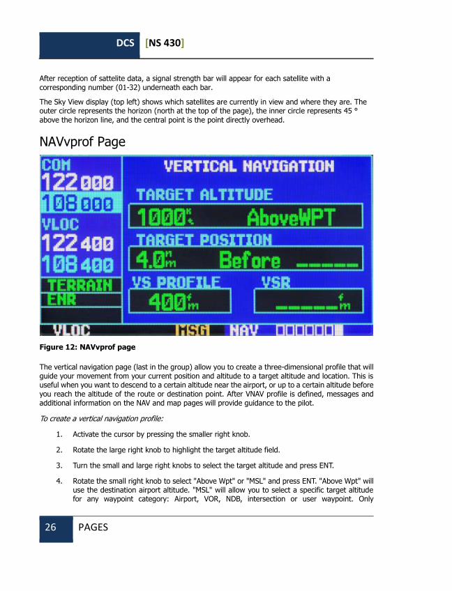
After reception of sattelite data, a signal strength bar will appear for each satellite with a corresponding number (01-32) underneath each bar.
The Sky View display (top left) shows which satellites are currently in view and where they are. The outer circle represents the horizon (north at the top of the page), the inner circle represents 45 °
above the horizon line, and the central point is the point directly overhead.
NAVvprof Page
Figure 12: NAVvprof page
The vertical navigation page (last in the group) allow you to create a three-dimensional profile that will guide your movement from your current position and altitude to a target altitude and location. This is useful when you want to descend to a certain altitude near the airport, or up to a certain altitude before you reach the altitude of the route or destination point. After VNAV profile is defined, messages and additional information on the NAV and map pages will provide guidance to the pilot.
To create a vertical navigation profile:
1. Activate the cursor by pressing the smaller right knob.
2. Rotate the large right knob to highlight the target altitude field.
3. Turn the small and large right knobs to select the target altitude and press ENT.
4. Rotate the small right knob to select "Above Wpt" or "MSL" and press ENT. "Above Wpt" will use the destination airport altitude. "MSL" will allow you to select a specific target altitude for any waypoint category: Airport, VOR, NDB, intersection or user waypoint. Only

[NS 430] DCS
BELSIMTEK 27
"AboveWPT" is used in the current version.
5. Turn the small right knob to select the distance to the target from the target reference waypoint and press ENT. If the target altitude appears on the reference waypoint, enter a value of zero.
6. 6. Turn the small right knob to select the "Before" or "After" the target and press ENT. This setting is always designated when the profile coordinates define a point that occurs before
or after reaching the reference waypoint. Only «Before» is used in the current version.
7. If you are using a flight plan, the target reference waypoint may be specified from the waypoints contained in the flight plan. By default, the last waypoint in the flight plan will be selected. To select a different waypoint, turn the small right knob to select the desired waypoint and press ENT. The current version allows for only the last waypoint of the flight plan to be used. By default, the profile uses a descent rate of 400 feet per minute. (>>2.03 m / sec). To change the speed, turn the large right knob to highlight the field "VS Profile"
and use the small and large right knobs to enter a new rate. Press ENT at the end.
8. After these steps, the system will indicate the desired vertical speed in the vertical navigation
page. You can expect the following when using the vertical navigation function:
1. One minute until the initial descent point, the message "Approaching VNAV Profile" will appear on-screen. The angle of descent (or climb) will also be fixed in place to prevent changes in the profile from altering the speed.
2. If selected, the vertical speed required (VSR) field on the navigation page and the Map page will display the required vertical speed to maintain the the proper descent (or climb) angle.
3. At 500 feet above (or below) the target height, the message "Approaching Target Altitude" will be displayed. The vertical speed required (VSR) field on the navigation and map pages
will be blank at this point.
4. Vertical navigation messages can be turned on or off. (By default, messages are turned off). Turning off messages will allow you to save the previous profile settings, without having to show messages when the VNAV function is not needed.
To display or hide VNAV messages:
1. Press the MENU button to display the options menu for VNAV
2. Upon selecting the option "VNAV Messages On?" Press ENT. Or, if messages have already been turned on and you want to turn them off, make sure that the selected option is "VNAV Messages Off?" And press ENT.
To restore factory settings:
1. Press the MENU button to display the options menu for the current page.
2. Rotate the large right knob to highlight "Restore Defaults?" and press ENT.
DCS [NS 430]
28 PAGES
WPT Page Group The second page group (WPT) provides information about airports, VOR, NDB, intersections, runways,
frequencies, and procedures stored in your database.
To quickly select the WPT page:
1. From any page, press and hold the CLR button for 2 seconds to select the NAVdef page. (You can omit this step if you have already viewed any of the main pages.)
2. Rotate the large right knob to select the WPT page group. "WPT" will appear in the lower right corner of the screen.
3. Rotate the small right knob to select the desired WPT page.
To enter a waypoint identifier:
1. Select the desired WPT page and click on the small right knob to activate the cursor.
2. Rotate the small right knob to select the first waypoint identifier symbol.
3. Turn the large right knob to select the next symbol field,
4. Turn the small right knob to select the desired character,
5. Repeat steps 3 and 4 until you select the needed identifier, then press ENT.
6. To remove the flashing cursor, press the small right knob.
After entering the WPT identifier, all six pages of the airport will indicate information for the selected airport. As you enter an identifier, the device will scan the database, indicating those WPTs that match the characters you entered for this point. If there are duplicates for the given code names or positions, they can be viewed by pressing the ENT key. If there are duplicates for the entered ID, a page for duplicate WPTs will appear after you select the ID (by using the large right knob and pressing ENT). By default, if there is no flight plan the system will perform a search of the nearest facilities; if there is a flight plan for the airport, information on the departure airport will then be loaded.
To select a waypoint identifier from a list of duplicates:
1. Select the desired airport or navigation aid identifier. 2. Upon pressing ENT, a window for duplicate waypoints will appear. Rotate the large right
knob to select the desired waypoint and press ENT. 3. To remove the flashing cursor, press the small right knob.

[NS 430] DCS
BELSIMTEK 29
WPTero Page
Figure 13: WPTero page
The airport position page displays the latitude, longitude and elevation of the selected airport. It also indicates the code name and location (city), the availability of fuel, existing approaches, radar coverage
and the type of airspace. The following descriptions and abbreviations are used:
POSITION
Latitude / Longitude in degrees / minutes or degrees / minutes / seconds, MGRS and UTM / UPS (only degrees / minutes are used in the current version)
ELEV In feet or metres
FUEL For civil airports the following fuel types are available: aviation fuel (80-87 / 100LL / 100-130 / Mogas), jet fuel or none. Data for this section is not available in the current version; thus, NONE is displayed.
APR Not implemented
RADAR Not implemented

DCS [NS 430]
30 PAGES
ARCPC Not implemented
The following options are available for this page: they are displayed when the MENU button is pressed:
• • Select Next FPL Apt? Displays the airport that is located nearest along the given flightplan.
• • Select Destination Apt? Displays the airport located on the final waypoint of the given flightplan.
WPTrunway
Figure 14: WPTrunway page
The airport runway page displays the identification, length, type of runway surface and lighting system for the selected airport. A map showing the boundaries of the runway and the surrounding area is also displayed on the runway page. The map scale is shown in the lower left corner of the screen and is configured using the RNG button. For airports with multiple runways this page will have information
for each runway.
To display information for each runway:
1. Click on the small right knob to activate the cursor.
2. Use the large and small knobs to select the name of the airport. Press ENT to select the airport.
3. Turn the large right knob to the indexing window listing all runways for the selected airport.

[NS 430] DCS
BELSIMTEK 31
4. Turn the small right knob to activate the menu with the runways.
5. Turn the large right knob to select a runway.
6. Press ENT to index information for the selected runway on the Airport Runway page.
7. To remove the flashing cursor, press the small right knob.
To set the map scale:
1. Click on the down arrow on the RNG button to show a smaller map area.
2. Press the up arrow on the RNG button to show a larger map area.
The airport runway page has an INFO window with the following information, from top to bottom:
The following options are available for this page: they are displayed when the MENU button is pressed:
• • Select Next FPL Apt? Displays the airport that is located nearest along the given flightplan.
• • Select Destination Apt? Displays the airport located on the final waypoint of the given flightplan.
Length / Width In feet
Surface Runway surface type: HARD, SOFT
Lighting Types of lighting: no lighting, part-time lighting, full-time coverage, unknown or frequency (for pilot-controlled lighting). In the current
version of the device this parameter is not displayed.

DCS [NS 430]
32 PAGES
WPTfreq
Figure 15: WPTfreq page
The airport frequency page displays radio frequencies and frequency types for the selected airport. If the selected airport has a LOC / ILS approach, the ILS localizer frequency will also be displayed on the airport frequency page. The airport frequency page can be used to quickly select and set the frequency of COM or VLOC.
To view the list of frequencies and tune to a desired frequency on the list:
1. Click on the small right knob to activate the cursor
2. Using the large and a small right knob enter the airport name or immediately press ENT.
3. Turn the large right knob to scroll through the list by placing the cursor on the desired frequency. If the list has more frequencies than can fit on the screen, a scroll bar on the
right side of the screen will indicate where you are on the list.
4. Press ENT to place the selected frequency in the standby field of the COM or VLOC window.
5. To remove the flashing cursor, press the small right knob.

[NS 430] DCS
BELSIMTEK 33
WPTapr Page
Figure 16: WPTapr page
The airport approach page displays the available procedures for the selected airport. Additional information may also be displayed if there are multiple initial approach fixes and feeder routes available.
To view the available approaches and transitions:
1. Click on the small right knob to activate the cursor
2. Using the large and a small right knob enter the airport name or immediately press ENT.
3. Rotate the small right knob to display the window with a list of all available approaches for the selected airport. Continue rotating the small right knob to select the desired approach.
4. Press ENT to select.
5. To remove the flashing cursor, press the small right knob.
The following options are available for the airport approach page. These can be displayed by pressing the MENU button:
• Load into Active FPL? allows the user to load the selected approach into the active flight plan without having to activate the approach. This option performs the same operation as the option "Select Approach?" on the procedures page. If successful, the user will automatically be moved to the FLPact page. If there is no flight plan, a new one will be created.

DCS [NS 430]
34 PAGES
• Load and Activate? allows the user to load the selected entry into the active flight plan and activate navigation guidance to transition to approach. If successful, the user is moved to the FLPact page.
• Select Approach Chnl - Not implemented in the current version. • Select Next FPL Apt? - Not implemented in the current version. • Select Destination Apt? - Not implemented in the current version.
WPTarr Page
Figure 17: WPTarr Page
The airport arrival page indicates the available standard arrival procedures (STAR) for the selected airport. If there are multiple transitions or runways associated with the arrival procedure, this information is also displayed.
To browse the list of available arrivals:
1. Click on the small right knob to activate the cursor.
2. Rotate the large right knob to place the cursor in the arrival procedure name field. (ARRIVAL).
3. Rotate the small right knob to display the window with a list of all available arrivals for the selected airport. Continue rotating the small right knob to select the desired arrival.
4. Press ENT.
5. Turn the large right knob to place the cursor in the transitions field. (TRANS).
6. Turn the small right knob to display the window with a list of all available transitions for the

[NS 430] DCS
BELSIMTEK 35
selected airport. Continue rotating the small right knob to select the desired transition.
7. Press ENT.
8. To remove the flashing cursor, press the small right knob.
On the airport arrival page are the following options, which can be displayed by pressing the MENU
button:
• Load into Active FPL? allows you to download the selected arrival procedure into the active flight plan. This is identical to loading arrival procedures from the procedures page.
• Select Next FPL Apt? Not implemented in the current version.
• Select Destination Apt? Not implemented in the current version.
WPTdep Page
Figure 18: WPTdep Page
The airport departure page displays the available Airport Standard Instrument Departure (SID) procedures for the selected airport. If there are multiple transitions or runway associated with the departure procedure, this information is also displayed.
To browse the list of available departures:
1. Click on the small right knob to activate the cursor.
2. Rotate the large right knob to place the cursor on the name of the departure procedure (DEP).

DCS [NS 430]
36 PAGES
3. Rotate the small right knob to display the window with a list of all available departures for the selected airport. Continue rotating the small right knob to select the desired departure.
4. Press ENT.
5. To remove the flashing cursor, press the small right knob.
The airport departure page has the following options that can be displayed by pressing the MENU button:
• Load into Active FPL? allows the user to download the selected departure procedure for creating a new flight plan. This action is identical to the procedure of downloading arrival
procedures from the procedures page.
• Select Next FPL Apt? Not implemented in the current version.
• Select Destination Apt? Not implemented in the current version.
WPTint Page
Figure 19: WPTint Page
The intersections page displays the latitude and longitude, region and country for the selected intersection. It also displays the identifier, radial, and distance to the nearest VOR, VORTAC or VOR /
DME.
Intersections may only be selected by their identifier as described in the preceding pages.
The following symbols and abbreviations are used:

[NS 430] DCS
BELSIMTEK 37
REGION Region name
POSITION Latitude / Longitude (in degrees / minutes or degrees / minutes /
seconds), MGRS or UTM / UPS.
RAD Radial from the nearest VOR, in degrees magnetic or degrees true (depending on system configuration)
DIS Distance from the nearest VOR in nautical miles / land miles / kilometers (depending on the system configuration)
NEAREST VOR Nearest VOR
ATTENTION: The VOR displayed on the intersections page is the closest VOR, not necessarily the VOR
that is used to define the intersection.
WPTndb Page
Figure 20: WPTndb Page
The NDB page displays the code name, city, region / country, latitude and longitude for the selected
NDB. The frequency is also displayed.

DCS [NS 430]
38 PAGES
NDBs may be selected by identifier as described in the preceding pages.
The following symbols and abbreviations are used:
FACILITY, CITY &
REGION Name of the city and region
POSITION Latitude / Longitude (in degrees / minutes or degrees / minutes / seconds), MGRS or UTM / UPS.
FREQ The frequency in kHz
WPTvor Page
Figure 21: WPTvor Page
The VOR page displays the code name, city, region / country, the magnetic variation, latitude and
longitude for the selected VOR. The frequency is also displayed.
NDBs may be selected by their identifier as described in the preceding pages (misplaced?)
The following symbols and abbreviations are used:
FACILITY, CITY &
REGION Name of the city and region

[NS 430] DCS
BELSIMTEK 39
POSITION Latitude / Longitude (in degrees / minutes or degrees / minutes /
seconds), MGRS or UTM / UPS.
FREQ The frequency in kHz
WPTuser Page
Figure 22: WPTuser Page
In addition to information on airports, VOR, NDB, and intersections contained in the database, the G430 allows you to store up to 1,000 user-defined waypoints. The user waypoint page displays the waypoint name (up to five characters in length), the identifier, radial between two reference waypoints
and the distance to one reference waypoint, as well as the latitude / longitude of the user waypoint.
The following symbols and abbreviations are used on the user waypoint page:
REF WPT Region name
POSITION Latitude / Longitude (in degrees / minutes or degrees / minutes /
seconds), MGRS or UTM / UPS.

DCS [NS 430]
40 PAGES
RAD Radial from nearest VOR, in degrees magnetic or degrees true
(depending on system configuration)
DIS Distance from the nearest VOR in nautical miles / land miles / kilometers
(depending on the system configuration)
User waypoints are created and edited on the user waypoint page. To create a new user waypoint simply enter the name (ID) and the position, or enter a reference waypoint, with radial and distance
from it to the user waypoint (Not implemented in the current version.)
To create a new user waypoint for your current location:
1. On the user waypoint page, click the small right knob to activate the cursor.
2. Use the small and large right knobs to enter the name of the new waypoint.
3. Press ENT to confirm the name. The cursor will move to the position field at the bottom of the page which displays your current position.
4. Press ENT twice to confirm the position.
5. After the "Create?" prompt appears, press ENT.
To create a new user waypoint by entering its position (latitude / longitude):
1. Follow steps 1-5 of the previous section
2. Use the small and large right knobs to enter the position coordinates for the new waypoint, then press ENT to confirm the latitude and longitude points.
3. When the "Create?" prompt appears, press ENT to save the new waypoint.
To create a new user waypoint through a reference waypoint:
Not implemented in the current version.
User waypoint page options:
The user waypoint page provides the following options which can be displayed by pressing MENU:
• View User Waypoint List? Displays a list of all custom waypoints currently stored in the system memory.
• Delete User Waypoint? Deletes the selected waypoint from memory.
• Crossfill - Interaction between devices. Not implemented in the current version.
The User waypoint list allows you to view or delete the selected user waypoint stored in memory. Editing is not implemented in the current version of the simulation.
To view user waypoints from the list:

[NS 430] DCS
BELSIMTEK 41
1. Select the user waypoint list from the menu by using View User Waypoint List function.
2. Rotate the large right knob to highlight the desired user waypoint.
3. Press ENT to display the user waypoint page for a selected waypoint. On this page you may view all the information that defines the user waypoint and its position.
To delete a user waypoint from the list:
1. Select the user waypoint list from the menu by using the Delete User Waypoint? function.
2. Rotate the large right knob to highlight the desired user waypoint.
3. Press ENT to delete the selected waypoint

DCS [NS 430]
42 PAGES
AUX Page Group The current version of the instrument features the following pagegroup and their points:
To quickly select the AUX pagegroup:
4. From any page, press and hold the CLR button for 2 seconds to select the NAVdef page. (You can omit this step if you have already viewed any of the main pages.)
5. Rotate the large right knob to select the AUX page group. "AUX" will appear in the lower right corner of the screen.
6. Rotate the small right knob to select the desired AUX page.
AUXfpl Page
Figure 23: AUXfpl page
The flight planning page allows the user to plan their flight, fuel cosumption, calculation of the barometric altitude by tH, true airspeed and wind in flight, and the crossfill (inter-device exchange) function for transferring flightpaths and user-made waypoints to another NS 430 device. Selecting the menu will display the corresponding pages that show additional information and functions.

[NS 430] DCS
BELSIMTEK 43
To select any of the menu options from the flightplan page:
1. Activate the cursor by pressing the smaller right knob
2. Rotate the large right knob to select the desired option, then press ENT.
The following options are available:
Trip Planning — Allows the pilot to view information about the intended track (DTK), distance (DIS), flight time (ETE), safe altitude along the route (ESA) and estimated time of arrival (ETA) for the flight
directly between two specific points and on the route for any programmed flight plan.
Fuel Planning – Indicates the minimum required fuel amount for travel directly between two specific points, or for the preprogrammed flightpath. The fuel planning function requires the pilot to enter the initial amount of fuel (FOB) and consumption rate (FF). You can also enter a different flight speed (GS) to view fuel consuption information based on different flight times. If your installation includes a fuel flow sensor, the information is accounted for automatically and the pilot has no need to enter it manually.
Density ALT / TAS / Winds — Indicates the theoretical altitude at which the aircraft would fly in the presence of some external conditions, including the indicator altitude (IND ALT), barometric pressure (BARO), and total head temperature (TAT). This version of the menu calculates the true airspeed (TAS) based on the above values and the instrument speed. This menu option also allows the pilot to calculate the direction and speed of the wind in flight, head and tailwinds based on the calculated density altitude values, true airspeed, airplane heading (HDG) and ground speed..
Crossfill — not implemented in the current version.
Scheduler — Displays reminder messages (i.e. "Change oil", "Switch fuel tanks", "Overhaul", etc.). Simultaneous, periodic and event-based messages are supported. Simultaneous messages appear once after the timer expires and appear once every time the system is turned on, until the message is deleted. Periodic messages automatically set the timer to its initial value after the message is displayed. Event-based messages are not set on timers, but at specific dates and times.

DCS [NS 430]
44 PAGES
AUXutil page
Figure 24: AUXutil page
The AUXutil/procedures page provides access (through the options menu) to checklists, a timer with forward and reverse counts, flight timers, flight statistics, RAIM (Receiver Autonomous Integrity Monitoring) prediction, sunrise / sunset time calculations and information on the software and database versions. Selecting an option from the menu will display the corresponding page with additional information and functions.
To select any of the menu options from the procedures page:
1. Activate the cursor by pressing the smaller right knob
2. Rotate the large right knob to select the desired option, then press ENT.
The following options are available:
Checklists - Provides up to 9 different checklists containing up to 30 items each.
Flight Timers — provides access to timers with stopwatch and countdown functions, as well as automatic recording of take-off time and full flight time. The take-off time and the total flight time are
recorded each time the system is switched on or when the speed reaches 30 knots.
Trip Statistics — provides an indicator of the total distance traveled (odometer), average speed and maximum speed. These readings can be reset (individually or simultaneously) by pressing the MENU button to display the options window.
Software Versions — Provides information about the version of the operating system of the GPS receiver, communications transceiver, VOR / ILS receiver and main processor. The version page also shows the type of database and its expiration date, along with the version and type of the ground-based database.

[NS 430] DCS
BELSIMTEK 45
Sunrise/Sunset— allows you to calculate the time of sunrise / sunset for any selected waypoint or current location for a given time.
AUXsetup1 Page
Figure 25: AUXsetup1 page
The Setup 1 page provides access (via the menu options) to alerts for SUA areas, CDI scale setting, arrival warnings, measurement unit settings, location formats, map parameters (ellipsoids), and local time or UTC indication settings. Selecting an option from the menu will display the corresponding page with additional information and functions.
To select any of the menu options from the setup 1 page:
1. Activate the cursor by pressing the smaller right knob
2. Rotate the large right knob to select the desired option, then press ENT.
The following options are available:
Airspace Alarms — Not implemented in the current version
CDI/Alarms — allows you to determine the scale of the deviation indicator scale from the NS 430's course line. The scale values represent the total deviation of the indicator in both directions. The default setting is "Auto", which begins calculating the scale from 5 mm and reduces it to 1 mm on approach, and then to 0.3 mm on the landing approach. To automatically configure the zoom, you must first have a flight route, or have DIRECT mode activated with the airport or destination approach point, or be at a distance of 30mm from the destination airport. Please note that the RAIM protection limits listed
below change automatically when the device is set to "AUTO":

DCS [NS 430]
46 PAGES
CDI Scale RAIM protection
+/-5.0 mm or Auto (enroute) 2.0 mm
+/-1.0 mm or Auto (approach) 1.0 mm
+/-0.3 mm or Auto (final) 0.3 mm
The "AUTO" setting for the ILS deflection indicator allows the GNS 430 to automatically switch the external CDI from the GPS receiver to the VLOC receiver on the final approach path. (See page 82.) If
necessary, select "MANUAL" to manually switch the CDI.
The arrival warnings provided on the CDI/alarms page can be set to display messages when approaching a specified distance to the final destination (DIRECT TO or the end point of the route). When you approach this point at a specified distance (up to 99.9 units) you will receive a message
displaying "Arrival at [WPT ID]".
Units / Mag Var — allows you to configure the displayed data in standard or metric units. These
settings relate to distance, speed, altitude, fuel, pressure and temperature.
Position / Map Datum — configures the information pertaining to the displayed format of
geolocation and map data (using an ellipsoid).
Date / Time — Provides time format settings (local or UTC, 12- or 24-hour) and local time offset relative to UTC. UTC (also called "GMT" or "zulu") date and time values are calculated directly from GPS satellite signals and can not be changed. If you prefer to use local time, simply determine the time
offset by adding or subtracting the correct number of hours.

[NS 430] DCS
BELSIMTEK 47
AUXsetup2 page
Figure 26: AUXsetup2 page
The setup 2 page provides access (through the options menu) to the indicator settings (brightness, contrast), to the search parameters for nearest airports, and to frequency sharing options (25 or 8.33 kHz) of the connected transceiver. After selecting a menu option, a corresponding window appears, providing access to various system settings. Selecting an option from the menu will display the
corresponding page with additional information and functions.
To select any of the menu options from the setup 2 page:
1. Activate the cursor by pressing the smaller right knob
2. Rotate the large right knob to select the desired option, then press ENT.
The following options are available:
Display — allows you to customize the display for optimal visibility under all conditions. There is an automatic backlight that uses the built-in photocell (in the upper left part of the display frame) to adjust the display parameters without external interference. Automatic contrast adjustment sets the contrast of the display depending on the current temperature of the instrument. You can choose to manually
adjust the contrast and brightness at your own discretion.
Nearest Airport Criteria — Specifies the minimum length and type of runway used to determine the nine nearest airports on the nearest airport page. The minimum length of the strip and / or its type can be entered to filter out airports with small runway lengths and incompatible runway types. The
default setting is "0 ft" and "any".
COM Configuration — allows you to select the frequency sharing of the 8.33 kHz or 25.0 kHz VHF
channels.

DCS [NS 430]
48 PAGES
NRST Page Group The fourth page group (NRST) will provide you with detailed information about the nearest airports, VOR, NDB, Intersections and user waypoints within a 200-mile radius of your current location. In addition, the NRST pages include the five nearest flight service station (FSS) and center points of communication (ARTCC / FIR). Plus, it warns the pilot about any special use (SUA), or controlled airspace that may be nearby. In the current implementation, data is available only for the Caucasus
region.
To quickly select an NRST page:
1. From any page, press and hold the CLR button for 2 seconds to select the NAV page. (You can skip this step if you are already on one of the main pages.)
2. Rotate the large right knob to select the NRST pagegroup. "NRST" appears in the lower right corner of the screen.
3. Rotate the small right knob to select the desired NRST page.
Not all the nearest airports, VOR, NDB, intersections or user waypoints can be displayed on the appropriate NRST page simultaneously. The closest airports page displays detailed information for the three closest airports; the scroll bar on the right side of the screen shows which part of the list can be seen at the moment. The closest SUA page displays detailed information for the three closest special use air spaces. The NRST pages for VOR, NDB, intersections and user waypoints display five waypoints simultaneously. The remaining items in the waypoint list may be viewed by turning the large right knob.
To view a list of the nearest airports, VOR, NDB, intersection or user waypoint SUA spaces:
1. Select the desired NRST page, as described above.
2. Press the small right knob to activate the cursor.
3. Turn the large right knob to scroll through the list. The scroll bar on the right side of the
screen will indicate which part of the list can be seen at the moment.
4. Press the small right knob to remove the flashing cursor.
The pages for the nearest ARTCC and FSS provide detailed information for the five nearest stations - displaying only one station at a time. Additional information can be viewed using the large right knob.
For a list of the nearest flight service stations or points of contact:
1. Select the desired page NRST, as described in the above
2. Press the small right knob to activate the cursor.
3. Rotate the small right knob to scroll through the list.
4. Press the small right knob to remove the flashing cursor.

[NS 430] DCS
BELSIMTEK 49
NRSTapt Page
Figure 27: NRSTapt Page
The nearest airport page displays the identifier, symbol, bearing and distance to the nearest airports (within 200 miles of your current location). Also displayed for each airport on this page is the best available approach, the common traffic advisory frequency (CTAF), and the length of the longest runway.
The nearest airport page can be used to quickly configure the COM transmitter to the nearest airport. The selected frequency is placed in the reserve field of the COM window and is activated with the C↕ button.
To quickly set the recommended CTAF frequency from the nearest airport page:
1. Select the nearest airport page, as described above
2. Press the small right knob to activate the cursor.
3. Turn the large right knob to scroll through the list, highlighting the communications frequency
with the airport.
4. Press ENT to move the selected frequency to the reserve field of the COM window.
5. Click C↕ to activate the selected frequency.
6. Press the small right knob to remove the flashing cursor.
Additional communication frequencies and runway information are available from the nearest airport page by highlighting the identifier of the desired airport and pressing the ENT button.

DCS [NS 430]
50 PAGES
To view additional information for the nearest airport:
1. Select the nearest airport page, as described above
2. Press the small right knob to activate the cursor.
3. Turn the large right knob to scroll through the list, highlighting the identifier of the desired
airport.
4. Press ENT to display the airport location page for the selected airport.
5. To view additional pages for the selected airport's waypoints (including runway pages and communication frequencies) turn the small right knob to display the additional waypoint
pages.
NRSTint Page
Figure 28: NRSTint Page
The closest intersections page shows a list of intersections and allows the user to see detailed
information about a particular intersection.
For detailed information about an intersection:
• Select the nearest intersection of the page as described above.
• Press the small right knob to activate the cursor.
• Use the large right knob to select a specific intersection.

[NS 430] DCS
BELSIMTEK 51
• Press ENT to go to the WPTint page to view more detailed information.
NRSTndb Page
Figure 29: NRSTndb Page
The nearest NDB page is used to quickly tune the COM transmitter to the closest EPTK. The selected frequency is placed in the reserve field of the com window and is activated by the C↕ button.
For quick adjustment of the recommended CTAF frequency from the nearest airport page:
1. Select the nearest node page, as described above
2. Press the small right knob to activate the cursor.
3. Turn the large right knob to scroll through the list, highlighting the communications frequency
with the node.
4. Press ENT to move the selected frequency to the reserve field of the COM window.
5. Click C↕ to activate the selected frequency.
6. Press the small right knob to remove the flashing cursor.
The nearest NDB page shows a list of these nodes and allows you to view detailed information about
a specific NDB.
For detailed information on an NDB:
1. Select the nearest NDB page as described above.

DCS [NS 430]
52 PAGES
2. Press the small right knob to activate the cursor.
3. Use the large right knob to select the specific NDB.
4. Press ENT to go to WPTndb page to access more detailed information if you have selected an NDB.
NRSTvor Page
Figure 30: NRSTvor Page
Page nearest VOR displays the identifier, symbol, bearing and distance to the nearest VOR (within 200 miles of your current location). For each VOR, this page also indicates the frequency, and can be used to quickly tune the VOR receiver to the closest VOR. The selected frequency is placed in the reserve field of the VLOC window and is activated with the V↕ button.
To quickly adjust the recommended VOR frequency from the nearest VOR page:
1. Select the nearest VOR page, as described above.
2. Press the small right knob to activate the cursor.
3. Turn the large right knob to scroll through the list, highlighting the VOR communication
frequency.
4. Press ENT to move the selected frequency to the reserve field of the VLOC window.
5. Click V↕ to activate the selected frequency.
6. Press the small right knob to remove the flashing cursor.

[NS 430] DCS
BELSIMTEK 53
To view VOR information from the nearest VOR page:
1. Select the nearest VOR page
2. Press the small right knob to activate the cursor.
3. Turn the large right knob to scroll through the list, highlighting the identifier of the desired
VOR.
4. Press ENT to display the VOR page for the selected VOR.
NRSTuser Page
Figure 31: NRSTuser page
The nearest USER WPT page displays the identifier, symbol, bearing and distance to the nearest VOR (user waypoint?) (within 200 miles of your current location).
To view USER WPT information from the nearest USER WPT page:
1. Select the nearest USER WPT page.
2. Press the small right knob to activate the cursor.
3. Turn the large right knob to scroll through the list, highlighting the identifier of the required
USER WPT.
4. Press ENT to display the USER WPT page for the selected USER WPT.

DCS [NS 430]
54 PAGES
NRSTartcc Page
Figure 32: NRSTartcc page
The nearest center page displays the code name, bearing and distance to the five nearest air traffic control centers (ARTCC) within 200 miles of your current location. For each ARTCC this page also indicates the communications frequency and can be used to quickly tune the COM receiver settings to the frequency of an ARTCC. The selected frequency is placed in the reserve field of the COM window
and is activated by the C↕ button.
To quickly tune the recommended ARTCC frequency from the nearest ARTCC page:
1. Select the nearest ARTCC page, as described above.
2. Press the small right knob to activate the cursor.
3. Turn the large right knob to scroll through the list, selecting the desired ARTCC.
4. Rotate the large right knob to scroll through the list, selecting the desired frequency.
5. Press ENT to move the selected frequency in to the reserve field of the COM window.
6. Click C↕ to activate the selected frequency.
7. Press the small right knob to remove the flashing cursor.
The current version of the simulator displays data only for the Caucasus region.

[NS 430] DCS
BELSIMTEK 55
NRSTfss Page
Figure 33: NRSTfss page
The nearest service stations page displays the code name, bearing and distance to the five nearest service stations within 200 miles of your current location. For each FSS this page also indicates the communications frequency and can be used to quickly configure the COM receiver to the FSS frequency. The selected frequency is placed in the reserve field of the COM window and is activated by the C↕
button.
To quickly tune the recommended frequency of FSS from the nearest FSS page:
1. Select the nearest service station page
2. Press the small right knob to activate the cursor.
3. Turn the large right knob to scroll through the list, selecting the required service station.
4. Rotate the large right knob to scroll through the list, selecting the desired frequency (COM frequency, or VOR frequency for dual operation).
5. Press ENT to move the selected frequency to the reserve field of the COM or VLOC windows.
6. Press C↕ or V↕, respectively, to activate the selected frequency.
7. Press the small right knob to remove the flashing cursor.
The current version of the simulator displays data only for the Caucasus region.

DCS [NS 430]
56 PAGES
NRSTspace Page
Figure 34: NRSTspace page
The last page in the NRST page group is the nearest SUA page which will warn you of the nine nearest controlled or special use airspaces in the vicinity of your flight plan. Warnings appear in accordance
with the following conditions (not implemented in the current version):
1. If your course takes you inside the airspace within the next 10 minutes, the message "special use airspace ahead less than 10 minutes" will appear. On the nearest SUA page the airspace will be displayed as "Ahead".
2. If you are within a 2-mile radius of the airspace and your current course takes you inside the airspace, the message "special use airspace near and ahead" will appear. "Within 2nm of airspace"
will be displayed on the nearest SUA page .
3. If you are within a 2-mile radius of the airspace and your current course will not lead you inside the airspace, the message "near special use airspace less than 2 nm" will appear. "Ahead <2nm" will be displayed on the nearest SUA page.
4. If you have entered the airspace, the message "Inside special use airspace" will appear. "Inside
special use airspace" will be displayed on the nearest SUA page.
Note that the airspace alerts are based on three-dimensional data (latitude, longitude, and altitude) to avoid messages caused by noise. Warnings for controlled airspace are also divided to provide full information for any nearest special airspace. After satisfying one of the conditions described above an
alarm will flash to warn you with a message on the SUA.
The current version of the simulator displays data only for the Caucasus region.

[NS 430] DCS
BELSIMTEK 57
FPL Page Group G430 allows the user to create up to 20 different flight plans with up to 31 waypoints in each. The flight plan page group consists of two pages that are accessible by pressing the FPL button. Flight plan
pages will allow you to create, copy and edit flight plans.
FPLact Page
Figure 35: FPLact Page
The active flight plan page provides information and editing functions for flight plan "0" - the flight plan currently in use for navigation. After activating the flight plan or the DIRECT-TO function, the active flight plan page will show each waypoint for the flight plan (or a single waypoint for DIRECT-TO) along
the intended track (DTK) and distance (DIS) for each flight section.

DCS [NS 430]
58 PAGES
Figure 36: FPLact Page
To add a waypoint using the small left knob:
1. From the Active Flight Plan page, press the small right knob to activate the cursor.
2. Rotate the large right knob to highlight the identifier of the waypoint to which you want to add a
subsequent waypoint.
3. Turn the small left knob to display a selection window with a list of waypoints.
4. Using the large and a small knobs enter the waypoint identifier. If the waypoint is unique then a prompt will appear to select it. If there are several such waypoints, a message box and menu will
appear.
5. Press ENT.
6. If there was more than one waypoint, a menu will appear. Using the large right knob select the desired waypoint and press ENT again.
7. Press ENT to confirm the chosen waypoint.
To delete a waypoint using the CLR button:
1. From the Active Flight Plan page, press the small right knob to activate the cursor.
2. Rotate the large right knob to highlight the identifier of the waypoint to which you want to add a subsequent waypoint.
3. Press CLR to display the confirmation window..

[NS 430] DCS
BELSIMTEK 59
The FPLact page has the following options that can be displayed by pressing the MENU button:
• Copy Flight Plan? Creates a copy of the current flight plan.
• Invert Flight Plan? Inverts the current flight plan.
• Delete Flight Plan? Deletes the current flight plan.
• Select Approach? Selects a landing approach.
• Select Arrival? Selects an arrival.
• Select Departure? Selects a departure.
• Change Fields? Edits the displayed parameters.
• Restore Defaults? Restores the displayed parameters to their defaults.
FPLcat Page
Figure 37: FPLcat page
The flight plan catalog page will allow you to create, copy and edit flight plans. Flight plans, numbered from 1 to 19, are used to save the flight plan for future use. Flight plan "0" is used exclusively for the current in-use flight plan. Each time you activate a flight plan, it is automatically saved as flight plan 0, overwriting the previously active flight plan.
To create a new flight plan:

DCS [NS 430]
60 PAGES
1. Press the FPL button and rotate the small right knob to display the flight plan catalog.
2. Press the MENU button to display options for the flight plan catalog.
3. Turn the large right knob to highlight "Create New Flight Plan?" and press ENT.
4. A blank flight plan page will appear for the nearest location.
5. Repeat the necessary steps for entering the ID for each additional flight plan waypoint.
6. Once you have entered all the waypoints, press the small right knob.
7. To return to the flight plan catalog use the small right knob.
To add waypoints to the existing flight plan:
1. Press the FPL button and rotate the small right knob to display the flight plan catalog.
2. Press the small right knob to activate the cursor.
3. Turn the large right knob to highlight the desired flight plan and press ENT.
4. Follow the instructions on the FLPact page.
To remove a waypoint from the current flight plan:
1. Press the FPL button and rotate the small right knob to display the flight plan catalog.
2. Press the small right knob to activate the cursor.
3. Turn the large right knob to highlight the desired flight plan and press ENT.
4. Follow the instructions on the FLPact page.
To activate a flight plan:
1. From the flight plan catalog page, click the small right knob to activate the cursor.
2. Press the MENU options to display the flight plan directory window.
3. Turn the large right knob to highlight "Activate Flight Plan?" and press ENT.
To invert the flight plan:
After departing on the flight plan, you can invert the route to navigate back to your initial point of
departure.
1. Follow the steps described above to activate the flight plan.
2. On the active flight plan page, press MENU to display the options window of the active flight plan.
3. Turn the large right knob to highlight "Invert Flight Plan?" and press ENT. The initial flight plan will be saved in your flight plan directory.

[NS 430] DCS
BELSIMTEK 61
To create a copy of the flight plan:
If you want to save the current flight plan (flight plan "0"), make sure that you copy it to one of the catalog's open flight plans (1-19) before it is canceled, overwritten or erased. It is possible to create a
copy for any flight plan.
1. From the Active Flight Plan page, press MENU to display the options window of the active flight
plan.
2. From the flight plan catalog page, click the small right knob to activate the cursor, turn the large right knob to highlight the flight plan that you want to copy, then press MENU to display the flight plan catalog options.
3. Turn the large right knob to highlight "Copy Flight Plan? 'and press ENT.
To delete a flight plan:
Once you've finished using a flight plan, it can be easily removed from the directory or page of the
active flight plan.
1. From the Active Flight Plan page, press MENU to display the options window of the active flight
plan.
2. From the flight plan catalog page, click the small right knob to activate the cursor, turn the large right knob to highlight the flight plan that you want to delete, then press MENU to display the options menu of the flight plan catalog.
3. Turn the large right knob to highlight "Delete Flight Plan? 'and press ENT.
The flight plan catalog has the following options:
• Activate Flight Plan? - Allows you select a flight plan for navigation use
• Create New Flight Plan? - Allow you to create a new flight plan,
• Crossfill? - Allows you to transfer flight plans between two G430 units with double installation. The current version does not support this option.
• Copy Flight Plan? - Allows you to copy the selected flight plan to a new flight plan. Copying is useful for duplicating an existing flight plan before making any changes.
• Delete Flight Plan? - Allow you to delete the selected flight plan from memory. Removal of the flight plan does not destroy individual waypoints contained in the flight plan from a database or custom waypoint memory.
• Delete All Flight Plans? - Allow you to remove all flight plans except the active flight plan.

DCS [NS 430]
62 PAGES
DRCT Page
Figure 38: DIRECT page
One of the advantages of G430 is the ability to fly straight to the point of destination or fly from point to point without the use of ground-based navigation aids. In order to ensure convenient and efficient navigation, the G430 offers two basic methods of selecting a destination: the DIRECT-TO mode and enroute navigation. Direct-to mode provides the opportunity to create a direct path from your current location to your destination. Navigation data on the various navigation pages will ensure flight control up until direct-to mode is canceled or replaced by a new destination point.
FLT Flight plan number
NRST Nearest waypoint
CRS (Not implemented in current version)
To activate DIRECT-TO to a given destination point:
1. Press the DIRECT-TO button. This will display a selection page for the direct-to waypoint with a
highlighted waypoint identifier field.
2. Use the small and large right knobs to enter the identifier of the desired destination.
3. Press ENT to confirm the selected waypoint,

[NS 430] DCS
BELSIMTEK 63
4. Once again press ENT to activate direct-to mode.
5. If you have deviated from the desired course (on CDI or HSI) while navigating to the waypoint, the direct-to function can be reused to return to the desired course and continue to move to the selected waypoint.
To select a destination from the Map Page:
1. From the map page, press the small right knob to display the target cursor.
2. Turn the small and large right knobs to move the cursor to the target destination.
3. If the cursor is placed on an existing airport, navigation aid, or user waypoint, the waypoint name
will be highlighted. Press the DIRECT-TO button to use the waypoint in the DIRECT-TO page.
4. Press ENT to activate DIRECT-TO mode.
To select the nearest airport or other point as the DIRECT-TO destination:
1. Select NRST page group using the large right knob
2. Rotate the small right knob to display a window showing the nearest airports or other navigation
points.
3. Press the small right knob to activate the cursor.
4. Rotate the large right knob to highlight the nearest airport field or other navigation point field.
5. Press the DIRECT-TO button. A selection page will appear for the DIRECT-TO WAYPOINT with a
highlighted identifier field.
6. Press ENT once to confirm the selected waypoint, and a second time to activate DIRECT-TO mode..

DCS [NS 430]
64 PAGES
PROC Page
Figure 39: PROC Page
The G430 allows you to perform precision and non-precision approaches according to published instrumental approach procedures. All available approaches are stored in the database and are
automatically updated when you replace the cartridge with a new one.
The procedures page is displayed by pressing the PROC button. Procedures page provides direct access to approaches and arrival and departure procedures based on the active flight plan, direct-to mode, or a new flight plan from the nearest airport (of departure). In any case, the origin and destination airports should have procedures associated with them.
To select approaches, departure or arrival procedures:
1. Press the PROC button to display the procedures page.
2. Rotate the large right knob to highlight "Select Approach?", "Select Departure?" Or "Select Arrival?" and press ENT.
3. A window will appear with a list of the available procedures. Rotate the large right knob to highlight the desired procedure and press ENT. (When direct-to mode is selected, departure procedures are
offered for the nearest airport.).
4. Further actions are similar to the corresponding WPT page. For example, you can load and activate
procedures using the MENU button.
For precision and certain non-precision approaches it is necessary to remember that the GPS is used on approach only for monitoring; for basic navigation use the VLOC and CDI (or HSI) receivers. ILS

[NS 430] DCS
BELSIMTEK 65
approaches, for example, should be used when the VLOC receiver is turned on and tuned to the appropriate frequency, and connected to the external CDI (or HSI).
After selection of an approach it can be enabled for navigation from the procedures page. Activating approach will replace the current leg of the route to the approach leg, which will also automatically
change the CDI scale.
To activate approach:
Not implemented in the current version.
• From the procedures page, turn the right knob to highlight "Activate Approach?" and press ENT.
• A confirmation screen appears. Highlight "Yes?" and press ENT.
The other options for the procedures page allow you to activate the final approach segment. This option assumes that you will receive vectors to the final approach point (FAF) and fly to the course end intersection before reaching the FAF.
To activate an approach with vector to the endpoint:
Not implemented in the current version.
1. From the procedures page turn the right knob to highlight "Activate Vector-To-Final?" and press ENT.
2. A confirmation screen appears. Highlight "Yes?" and press ENT.
In many cases, it is easier to "download" the complete approach to the destination airport in advance. Later, when vectored to final, use the steps above to select "Activate Vector-To-Final?", which activates the inbound course to the FAF. Alternatively, activate the full approach using the option "Activate Approach?"
The G430 provides non-precision approaches using the built-in GPS receiver. The receiver can also be used as an additional aid for precision approaches, but for basic navigation the pilot must use the
localizer and glidescope receiver.
The approaches that are designed specifically for GPS are usually very simple and do not require overflying a VOR or NDB. Many non-precision approaches have overlays that allow you to fly an existing procedure (VOR, VOR / DME, NDB, RNAV, etc.) more accurately using GPS. For your information, there
are over 1,400 GPS-only approaches and more than 3,500 approaches with GPS coverage.
Many approaches are complex (compared to GPS-approaches). The G430 manages your flight on each approach segment - automatically transitioning from one section to another. On approach you can fly as "allowed" with full transition using any authorized inbound route or starting point of approach (IAF)
- or fly by vector to the end point of the transition.
Procedure for take-off
The system makes it possible to place the take-off procedures (SID) at the very beginning of the flight plan.

DCS [NS 430]
66 PAGES
To schedule takeoff:
1. Use the large and small left knobs to select the NAVdep page.
2. Press the small right knob to activate the cursor
3. Move the cursor to the DEP field. Rotate the small right knob and activate the available menu items.
4. Using the large knob, select the required DEP take-off procedure
5. Press ENT to confirm. Steps 3, 4 can be omitted if you are satisfied with automatically selected
procedure.
6. To turn off the cursor, press the small right knob.
7. Using the MENU button and the right most knob choose the option Load into FPL, which will copy the data to a new flight plan. The system will automatically go to the page FLPact, where the plan will
be displayed.
En-route flight procedure
The system allows for planning flight routes, creating a flight plan, and controlling the position and direction of flight.
To plan a flight route:
1. Use the FLP button to go to the FLPact page.
2. Turn on the cursor by pressing the small right knob.
3. Add the required number of points on the route by turning the small right knob to highlight the window for adding waypoints.
4. When you are finished adding points, press the small right knob to turn off the cursor.
5. Having finished scheduling, press the CLR button for 2 seconds to go back to the NAVdef page.
6. CDI Scale and other fields on the page will diagnose whether your flight is correct.
Landing procedures
Approach operations usually begin with these basic steps:
1. Select the destination airport using the DIRECT-TO button or as the last waypoint in the active flight
plan.
2. Select "Select Approach?" from the procedures page or of the options menu of the active flight plan.
3. Use the "Load into FPL" on the WPTapr page to load the entry for future use. This will bring in approach into the flight plan, but will retain your course until approach is activated.
4. Select "Select Arrival?" from the procedures page or from the options menu of the active flight plan.
5. Use "Load into FPL" from the WPTarriv page to load the entry for future use. This will bring the

[NS 430] DCS
BELSIMTEK 67
approach into the flight plan, but will retain your course until approach is activated.
6. Activate the full approach or final vector as you require. You may find it more convenient to
immediately activate the approach and skip the loading process.
Below are some of the approach operations. Not all of them are implemented in the current version
of the device.
“Procedure turn” Approach.
"Procedure turn" is a circuit approach and is stored as a separate phase of the overall approach procedure. For this reason, the G430 does not require any special action from the pilot other than those required to perform the actual reversal procedure, and besides that, what is required for any other type of approach.
This example uses a VOR approach to runway 03 of the KLYH Regional Airport, Linhburg (Virginia), and assumes departure from the KFDK municipal airport, Frederick (Maryland). These are the steps required
to set and fly to approach:
1. Before departure from KFDK, the destination airport is selected using the button DIRECT-TO or by
creating a flight plan for Linhburg.
2. While enroute, after 40-50 miles you will select the ATIS frequency to verify the usage conditions of the airport and runway. This is done by selecting the NAVCOM page and selecting the ATIS frequency from the list. This frequency is placed in the reserve window. Use the C↕ button to make the ATIS frequency active.
3. From the ATIS frequency, you will learn that runway 03 is in use and complies with your approach plan. Press the PROC button and select the entry "VOR 03", using these steps: On the transfer window select LYH VOR (IAF initial approach point). Then select "Load?" to load (but not activate) the approach.
4. After you have prepared for approach, press the PROC button, select "Activate Approach?" and press ENT.
Flying the procedure turn
1. Within a 30-mile zone from the destination airport, the G430 goes from "route" to "terminal" mode (displayed in the lower left corner of the screen). The transition to "terminal" mode is accompanied by a change in the CDI scale from 5 to 1 nautical mile (example above left).
2. A few miles to the initial approach fix (IAF), you may want to review the approach sequence. Press the FPL button to display the active flight plan page. Click on the small right knob and turn
the large right knob to view each approach segment.
3. After reaching the IAF (LYH), the lower right corner of the screen displays an alert ("NEXT DTK 205o"). Since the distance (DIS) to the IAF is zero, the warning is replaced by the prompt ("TURN TO 205o"). Dial an outside course of 205o to the CDI (or HSI) using the OBS button and starting
the procedure turn to this course.
4. Fly the outbound course, holding the arrow in the center of CDI.

DCS [NS 430]
68 PAGES
5. Once you have flown about 15 seconds after the final approach fix/FAF (LYH), the message "PROC TURN OK" will appear in the lower right corner of the screen. You can start the reversal procedure
at any time after receiving this message.
6. Turn left at 160o to begin the turn. Course control is provided relative to the outer segment of the final approach point. (The reversal procedure is displayed on the map page and is displayed as the active segment on the NAV and Active Flight Plan pages). The arrow on the CDI will start to
move to the right.
7. After approximately one minute, make a right turn at the intersection to 340o to intersect the internal course. The G430 will follow the inner portion to the end point of the FAF approach; the CDI needle will deflect to the opposite side to provide adequate sensitivity to the final course; and
"NEXT" will appear in the lower right corner of the screen
8. As the CDI needle begins to move to the center, make a right to 025o - the final approach course.
9. Within a 2-mile radius of the FAF the G430 will switch "Terminal" mode to "Approach" mode. The
CDI Scale will decrease from 1 to 0.3 nautical miles.
10. Once you reach the FAF, the warning "NEXT DTK 025o" will appear in the lower right corner of
the screen. Be sure to adjust the course for the terminal phase (FAF to MAP)
11. After crossing the FAF, continue to the MAP point (runway 03). Holding the arrow in the center to
fly to MAP, observing the minimum height specified for the approach.
12. After crossing the MAP above the OBS will display "SUSP", indicating that the automatic approach waypoint sequencing will be suspended at the MAP. "FROM" will be displayed on the NAV page and on the CDI, but course guidance along the final approach course will continue. If you want to perform an missed approach, use the OBS button to initiate a missed approach, as shown on the next page.
Below are specific operations for approach, some of which are still unavailable in the current version. (at the very least the DME arc entry)
Missed Approach
If, after passing the MAP, you can not see the runway, you need to execute a missed approach. The G430 will continue to guide you along the extension of the final course segment until you manually start the missed approach procedure (as mentioned earlier in reference to "SUSP", the OBS button is
used to initiate a missed approach.):
1. 1. Press the OBS button. The missed approach holding point (Munro, in this case, the SWARM
intersection) is offered automatically as the destination point.
2. 2. Follow the missed approach procedure as is permitted for approach, with the appropriate instructions. the G430 will guide you along the radial 053o from LYH VOR.
3. 3. You will receive a warning message in the lower right corner of the screen recommending entry procedures for the holding pattern ( "HOLD DIRECT", "HOLD PARALLEL" or "HOLD TEARDROP"). A timer will appear on the NAV page as you fly the holding pattern. The timer is automatically reset outside of the holding point, when you are abeam the holding point.

[NS 430] DCS
BELSIMTEK 69
The timer is reset again when you turn inward about 30 degrees). This will allow you to use a certain time (typically one minute) to fly the inbound and outbound legs of the holding
procedure.
4. 4. The G430 will provide flight guidance only within the holding pattern. When you move from the holding pattern to refly the approach (or a different one), press the PROC button to select "Select Approach?" Or "Activate Approach?" as described above. (Or, use the
DIRECT-TO button to select a different destination)
Approach with Hold
Beginning from the location where we ended the previous example, suppose that the weather conditions have led a missed approach at Linhburga airport, so we decide to fly to Farmville Airport
(KFVX).
1. Press the DIRECT-TO button.
2. Use the small and large right knobs to enter the destination airport identifier (KFVX).
3. Press the ENT key twice. Then select the GPS-approach to runway 21 at Farmville airport. This approach begins with a holding pattern at the starting point of the IAF, BODRY intersection.
4. Press the PROC button and select the "GPS 21" approach.
5. In the transition window, select the BODRY intersection as IAF. Also select "Activate?", to load and activate the entry.
6. After activating the approach the active flight plan page will be displayed. You can see the approach sequence by clicking on the small right knob and turning the big right knob. Press
the FPL button to return to the navigation pages.
7. As in the last example, within a 30-mile radius of the airport, the G430 will switch from
"enroute" mode to "terminal" mode, and the CDI scale will go from 5 to 1 nautical mile.
8. Just before the BODRY intersection point a warning will appear - "HOLD TEARDROP" - in the lower right corner of the screen to suggest the proper holding entry pattern ( "HOLD DIRECT" or "HOLD PARALLEL" can be offered instead in other similar approaches)
9. As mentioned in the example with the missed approach, the NAV page will display a timer when flying the holding pattern. Use this timer to fly one minute on the outer portion of the holding pattern. (The holding pattern will be displayed on the map page and displayed as the active leg on the NAV page and the active flight plan page).
10. When crossing the IAF "SUSP" will appear above the OBS, indicating that the automatic approach waypoint sequencing is suspended. After turning inbound, "SUSP" will be canceled and the G430 will return to automatic sequencing.
11. When you get to the BODRY intersection, a warning message will appear showing "NEXT DTK 209o" in the lower right corner of the screen
13. Inside the 2-mile radius of the FAF (DEPOY intersection) the G430 will switch from "terminal" to

DCS [NS 430]
70 PAGES
"approach" mode. The CDI scale will decrease from 1 to 0.3 nautical miles.
14. Once you reach the FAF, a warning message will appear showing "NEXT DTK 209o" in the lower right corner of the screen. Make any course adjustments necessary for the final course segment (from the FAF to MAP).
15. After crossing the FAF, the destination point becomes MAP (runway 21, the runway edge). Hold the needle in the center of the CDI, fly directly to the MAP, following the minimum permitted altitude. (Looking at the map page, you will notice that the final rate is displayed in red - the active section of the flight plan is always indicated by the color red - and a dashed line continues the course behind the MAP. Do not follow the continuation of the course; instead, follow the authorized procedures for missed approaches) .
16. After crossing the MAP, "SUSP" will be shown above the OBS indicating that the automatic sequencing of approach waypoints is suspended at MAP. Note that "from" will be displayed on the NAV and CDI pages, but course guidance along the final course will continue. If you want to
perform a missed approach, use the OBS button to start the missed approach.
DME Arc Approach.
The GPS overlay for DME arc approaches uses additional waypoints from the Jeppesen database to determine the arc. These waypoints are displayed using the letter D at the beginning of the name of the waypoint, followed by three digits indicating the radial where the waypoint is located. The last letter indicates the radius of the arc.
For example:
D258G indicates a DME waypoint ("D") in a 258o radial at DME 7 (as "G" is the 7th letter of the
alphabet).
When you are ready for a DME arc approach, you must perform one of the following steps to cross the
arc:
• Follow the specific radial for intersection with the IAF.
• Follow the ATC vector, which will allow you to cross the arc at any point along the arc.
This example is based on a flight from Hutchinson Municipal Airport (KHUT) (Kansas) to Forbes Field Airport (KFOE) in Toreka, Kansas. Approach 21 VOR / DME will be selected; the IAF will be waypoint "D258G".
1. 1. Select Forbes Field (KFOE) as the destination by pressing DIRECT-TO or setting it as the last waypoint in the flight plan.
2. 2. Press the PROC button and select the entry "VOR / DME 21". In the transitions window, select "D258G" as the IAF. Also select "Load?" (Or "Activate?", If you are ready for approach.) Within a 30-mile radius of KFOE, G430 switches from "enroute" mode to terminal mode, and
the CDI scale will go from 5 to 1 nautical mile.
3. 3. If you have not activated the approach (as described in step # 2), do it when you are
prepared for approach.

[NS 430] DCS
BELSIMTEK 71
4. 4. After reaching the IAF, a warning - "NEXT DTK 352o" - will appear in the lower right corner of the screen. Once the distance to the IAF is equal to 0, the message will become "TURN
TO 352o".
5. 5. Follow the arc, keeping the CDI arrow in the center. When using autopilot, the choice of FPU (??) in the CDI (or HSI) must be periodically updated to reflect the desired track (DTK) to ensure the appropriate path for the arc. Whenever the set required track differ by more
than 10 degrees, "Set course to ### o" will appear in your messages.
6. 6. The next approach point will be an intermediate fix marked as "D025G". Once you reach this point, the warning "NEXT DTK 205o" will appear in the lower right corner of the screen. Once the distance to the fixing point is be equal to 0, this warning will be replaced with "TURN TO 352O". Enter this course onto CDI using the OBS button and initiate a standard turn into this course.
7. 7. Before reaching the TOP VOR, the lower right corner of the screen will display the message "NEXT DTK 200o". Dial this course onto the CDI (or HSI), using the OBS button and turn to this course.
8. 8. Within a 2-mile radius of the FAF (FF 21; MRP Jeppesen) the G430 will switch from terminal to approach. The CDI scale will decrease from 1 to 0.3 nautical miles.
9. 9. Once you reach the FAF, a warning message will appear ("NEXT DTK 200O") in the lower right corner of the screen. Make any necessary course adjustments for final approach(from
the FAF to MAP).
10. 10. After crossing the FAF the destination point becomes MAP (runway 21, the runway edge). Hold the needle in the center of the CDI, fly directly to the MAP, and follow the minimum permitted altitude. (Looking at the map page, you will notice that the final course segment is displayed in red - the active section of the flight plan will always be displayed in red - and the dotted line continues the course behind MAP.
11. After crossing the MAP, "SUSP" will appear above the OBS indicating that the automatic waypoint sequencing is suspended at MAP. Note that "from" will be displayed on the NAV and CDI pages, but course guidance along the final approach course will continue. Does not follow this extended course. Instead, follow the authorized procedures for missed approach). If you want to perform missed approach, press the OBS button to activate missed approach.
Vector to Final
Let's examine a missed approach at the VOR / DME 21 in Forbes Field. Instead of following a DME arc, the tower instructs you to expect radar vectors to the final approach course. There are several ways to choose a "vectored to a landing direct" with the G430. The first two of the following points require less
load to perform:
• • When the setting is selected for the first time, select "VECTORS" in the transition window.
• • Load the full approach including the IAF in the transitions window. When you're ready, press PROC and select "Activate Vectors-To-Final?"
• • Load full set. Use the DIRECT-TO button (press twice) on the active flight plan page to
DCS [NS 430]
72 PAGES
select the required segment of the approach.
To select "VECTORS" from the transitions window:
1. Select Forbes Field, (KFOE) as the destination point using the DIRECT-TO button, or by setting it as the last waypoint in the flight plan.
2. Press the PROC button and select the entry "VOR / DME 21".
3. In the transitions window, select "VECTORS"
4. Select "Load?" (Or "Activate?" if you are ready for approach)
To enable vectors-to-final from the procedures page:
1. Select Forbes Field, (KFOE) as the destination point using the DIRECT-TO button, or by setting it as the last waypoint in the flight plan.
2. Press the PROC button and select the entry "VOR / DME 21".
3. In the transitions window select "D258G" as the initial approach point, then select "Load?"
4. If you are ready for approach, press the PROC button and select "Activate Vectors-To-Final?"
When vectoring to the runway, the CDI arrow will deflect from the center until you are established on final approach course. When the approach is activated, the map page will display a continuation of the final approach course in red (remember red is used to indicate the active leg of the flight plan) and the NAV page shows "VTF" as part of the active leg (as a reminder that the approach was activated with vector-to-final). In this example, we assume that the vectors of the control point will be perpendicular to the final course:
1. Within the 30-mile radius of KFOE the G430 will transition from "enroute" mode to "terminal" mode, and the CDI scale will go from 5 to 1 nautical mile.
2. Activate the approach if you have not yet done so. This will allow the G430 to provide guidance navigation to the final course.
3. ATC will instruct to turn left at 020o. At the same time you will be parallel to the final course in the opposite direction. The CDI arrow will deflect to the left.
2. ATC will instruct to turn left heading 110 °.
3. ATC will instruct to turn left heading 170 ° to cross the final approach course. Once you get close to the final approach course, the CDI needle will move to the center. (The illustration on the left shows that the needle has not yet returned to the CDI, as your current position is still 2.6-miles away to the right of the final approach).
4. After the arrow returns to the center of the CDI, perform the necessary course adjustments to establish a direct path to final approach. 2 miles from the FAF (FF21) the G430 will switch over to
approach mode from terminal mode. The CDI scale will change from 1 to 0.3 nautical miles.
5. Once you get close to the FAF, the lower right corner will show a warning - "NEXT DTK 200o".
Make the necessary corrections on the final approach segment (FAF to MAP).

[NS 430] DCS
BELSIMTEK 73
6. After crossing the FAF, destination point will be set to MAP ("RW21"). Holding the arrow in the center, fly directly to MAP, observing the minimum safe altitude allowed for this approach.
7. Once you have reached the MAP, the lower right corner will show warning about the waypoint ("APPRCHING WPT")
8. After crossing the MAP, "SUSP" will appear above the OBS indicating that the automatic waypoint sequencing is suspended at MAP. Note that "from" will be displayed on the NAV and CDI pages, but course guidance along the final approach course will continue. Does not follow this extended course. Instead, follow the authorized procedures for missed approach). If you want to perform
missed approach, press the OBS button to activate missed approach.
Course From Fix Flight Plan Legs
Certain approaches, SID, STAR and arrival procedures in the Jeppesen database contain course from fix flight plan legs. The G430 can download these legs into the flight plan, along with other data and
procedures to provide navigation along these legs.
There are three different types of course from fix legs:
Type 1: Course from fix to distance, or course from fix to DME distance
Course from fix to distance legs appear like normal waypoints, but the destination name must begin with "D" followed by the distance in tens of MM from a given point. This example uses the approach
VOR / DME RWY 25 in Palmdale, CA (KPMD) and includes a return course.
1. When you reach the initial approach fix (PMD), a warning message ( "NEXT DTK 070 °") alerting you to your arrival at the waypoint will be shown in the lower right corner of the screen. When the distance from the IAF reaches zero, the warning is replaced by a prompt to "TURN TO 070°". Enter the outbound course into the CDI (or HSI) using the OBS knob and begin the procedure turn to the course.
2. Fly the course approach, holding the CDI arrow in the middle. You are now on the course from fix to distance leg, as shown in the active route and NAV pages. Note the red line in the lower part of the image, which is the currently active approach leg. The distance displayed on both screens is the distance to the point "D13.0". The route automatically
switches to the next leg after "D13.0".
3. 13.0 MM from the FAF, a warning of your arrival ( "NEXT DTK 265 °") will be shown in the lower-right corner of the screen. Turn to intercept the final approach course and watch for the CDI needle to center.
4. Upon arrival at the intermediate point (CF25), a warning message appears: ("NEXT DTK 265 °"). Adjust your course accordingly.
5. 2.0 nautical miles from the FAF (THERO), the G430 will switch from terminal to approach mode. ("APR" will appear in the lower left corner of the screen, instead of "TERM".) CDI scale will change from 1.0 to 0.3 M, full scale deflection.
6. Upon arrival at FAF, "NEXT DTK 265 °" will appear in the lower right corner of the screen.
7. After crossing the FAF, the destination will switch to MAP (MA25). Holding the arrow in the

DCS [NS 430]
74 PAGES
center of CDI, fly to the MAP, observing the minimum required altitude according to the approach procedure
8. Upon arrival at MAP, a warning ( "APPRCHING WPT") will appear in the lower right corner of the screen.
9. Upon crossing MAP, "SUSP" will appear above the button indicating the suspension of the automatic waypoint sequencing at the MAP. If you need to perform a missed approach, use
the OBS button to initialize a missed approach as described below.
Type 2: Course from Fix to Altitude
Course from fix to altitude show a preset altitude in the active route page and NAV page. The missed approach sequence for the VOR / DME RWY 25 approach includes a course from fix to altitude leg.
In this example, the leg corresponds to the initial part of the missed aproach, which reads "climb to 5000 'on the PMD VOR R-282 departure course."
1. After crossing MAP, press the OBS button. This will automatically offer a missed approach sequence, starting with the course from fix to altitude leg. The warning "NEXT DTK 282 °" will appear in the lower right corner of the screen. Follow the procedures of the missed approach, as described in the published approach procedures in the instructions for the appropriate climb and course.
2. Pay attention to the fact that, in a few seconds after pressing the OBS button to begin automatic waypoint sequencing, "SUSP" reappears on the OBS button as the G430 temporarily suspends waypoint sequencing. This is normal during course from fix to altitude legs.
3. Fly the outbound course making sure that the CDI arrow is in the middle. The map page will show a picture showing the route from PMD VOR. The distance (DIS) in the NAV, map and
active flight plan pages will increase, displaying the distance back to the PMD VOR.
4. After reaching the desired altitude (5000 '), press the OBS button to return to the automatic
waypoint sequencing. Make sure that "SUSP" will not appear above the OBS button.
5. A warning ( "NEXT DTK 126 °") appears to guide you to the approach course. The desired course will depend on the ground speed and the distance from the PMD VOR. Cross and fly the approach course, holding the arrow in the center of the CDI.
6. On arrival at the PMD VOR (holding point for missed approaches), the message in the lower right corner of the screen will prompt you to enter the waiting area ( "HOLD PARALLEL"). When flying in the waiting area, a timer will appear on the NAV page. This will automatically
reset on each outbound and inbound portion of the holding pattern.
7. Note that the G430 will again display "SUSP" above the OBS. Automatic waypoint sequencing will be stopped at the missed approach holding area. The warning ("APPRCHING WPT") will appear in the lower right corner of the screen when approaching PMD VOR in the holding
pattern.
8. After leaving the holding area, press the PROC button to reactivate approach, or select
another approach, or press DIRECT-TO for flight to another destination waypoint. CEDURES

[NS 430] DCS
BELSIMTEK 75
Type 3: Course from fix to manual sequence
1. Course from fix to manual sequence legs appear in the active flight plan and map pages with the indicator "man seq" in place of the waypoint ID. An example of this type of leg in the COASTAL ONE DEPARTURE from Westfield, Massachusetts (Barnes Muni).
2. The example leg corresponds to the departure leg from the Barnes municipal airport and appears as follows on the active flight plan and NAV pages:
3. Select SID (CSTL1) from the procedures page. Then choose the runway (RW02, in this example) and the transition (GEDIC). See section 5 for instructions on SID choice.
4. After takeoff, the lower right corner of the screen will display "NEXT DTK 026 °" and "SUSP" directly above the OBS. You are now on the course from fix to manual sequence leg. The distance shown at the active flight plan, NAV and map pages is the distance from the given point (take-off runway in this example).
5. Fly the outbound course, holding the arrow in the center of CDI. After receiving permission to switch to the next leg, press the OBS button. Make sure that "SUSP" is not above the OBS. The warning ("NEXT DTK 186 °") will appear in the lower right corner of the screen directing you to a new waypoint (HFD VOR). The desired course will depend on the ground speed and the distance from the HFD VOR.
6. After pressing OBS, the G430 will automatically sequence waypoints for the remaining leg of the flight plan, including the transition.
ILS Approaches
Precision approaches can be created using the built-in VLOC (VOR / glidescope receiver). The GPS receiver may be used for flight control before reaching final approach, but the corresponding frequency in the VLOC window (on the left side of the screen) must be chosen and CDI output must be switched
from "GPS" to "VLOC".
1. For example, choose a flight from Laughlin (Arizona) to Flagstaff (KFLG) and select the entry for the ILS system on runway 21. The intersection "SHUTR" will be selected as the IAF, and includes an outbound leg and a procedure turn. Of course, vectors-to-final line can also be selected as described
above for non-precision approaches.
2. Select Flagstaff (KFLG) as a destination point, via the DIRECT-TO button or by setting it as the last
waypoint in the flight plan.
3. Press PROC and choose "ILS 21"
In the transitions window, select "SHUTR" as the IAS. Use "Load into FPL?" from the menu to load the procedure into the flight plan.
ILS Approaches
1. When activating an approach using ILS, the ILS system frequency will be automatically placed in the reserve field of the VLOC window. To use this frequency, press V↕ button to move it to the active frequency field.

DCS [NS 430]
76 PAGES
2. Within a 30-mile radius of KFLG, the G430 will switch from enroute to terminal mode and the CDI scale will go from 5 to 1 nautical mile
3. Activate the approach after receiving clearance, if you have not already done so.
4. After reaching the IAF (SHUTR), you will receive a warning in the lower right corner of the
screen: "NEXT DTK 352O".
5. If you have not already done so, press the button to activate V↕ ILS frequency.
6. When the range to the IAF would be equal to 0, the message will turn to "TURN TO 30O".
7. Fly the outbound course (030 o) while holding the arrow in the center of the external CDI
(or HSI).
8. After about 1 minute after you pass the intersection SHUTR, the warning "START PROC TURN" will appear in the lower right corner of the screen . You can start a reversal procedure at any time after receiving this notice.
9. Turn right at 075o to initiate the procedure turn. The G430 will not guide the flight through the turn. (Reversal procedure is displayed on the map page and is displayed as the active leg on the NAV page and the active flight plan page). The arrow of the external CDI starts
to move to the right (reverse sensitivity).
10. After about one minute, turn left 180o to course 255o up until ILS intersection. The G430 sequences to the inbound leg and the lower-right corner of the screen will show the warning "NEXT DTK about 210".
11. After the CDI needle starts to move towards the center, turn left at 210o - the ILS course. After the course to the FAF, the CDI automatically switches from GPS to the VLOC receiver
(if ILS frequency is activated, as indicated in paragraph # 4).
12. Once you reach SHUTR, in the lower left corner of the screen will show "0.30nm" indicating a CDI scale transition from 1 to 0.3 nautical miles. (This change is applied only to the NAV page's on-screen CDI, as the external CDI or NSI is now connected to VLOC receiver. The GPS will not be activated for a precision approach. Use VLOC receiver for the main navigation.)
13. Once you reach SHUTR, the warning "NEXT DTK about 210" appears in the lower right corner of the screen.
14. After crossing SHUTR the destination point becomes MAP ("RW21", runway edge). Hold the arrow of the external CDI (or HSI) in the middle and fly directly to the IDA, maintaining the minimum required altitude for the approach. Looking at the map page, you will notice that the final course segment is displayed in red - the active section of the flight plan will always be displayed in red - and the dotted line continues the course behind MAP.
15. As you approach MAP, the lower right corner of the screen will display the warning "APPRCHING WPT".
16. After crossing the MAP, "SUSP" will be shown above the OBS indicating that the automatic sequencing of approach waypoints is suspended at MAP. "From" will be displayed on the NAV

[NS 430] DCS
BELSIMTEK 77
and CDI pages, but course guidance along the final course will continue. Do not follow this continuation of the final leg. If you want to perform a missed approach, use the OBS button
to start the missed approach.
4. Messages System
The G430 uses a flashing "MSG" indicator in the bottom of the screen (right above the MENU button) to report the presence of important information or warning. Although many reports are advisory in nature, warning messages require your intervention. Whenever the indicator is flashing "MSG" press the MENU button to display the message. Press MENU again to return to the previous page.
Below are the possible messages and their definitions:
Approaching target altitude - Current GPS altitude - 500 feet from the final altitude of the vertical
navigation mode.
Approaching VNAV profile - you are one-minute away from the point of descent or climb (in vertical navigation mode.)
Arrival at waypoint - [AMP ID] - Your aircraft is at a set distance from the waypoint. This distance is set at setup page 1.
Auto CDI scale selected - The GNS has automatically reset the CDI scale upon execution of route navigation or approach. When selecting manual scale control (on setup page 1) the G430 automatically switches manual control to automatic 30 MM from the arrival airport. The system also returns to automatic operation after shutdown, manual control settings are NOT saved after switching off.
FPL is full - remove unnecessary waypoints - Shown when trying to add more than 31 points in the route.
Set course to [###] ° - Additional CDI / HSI must be installed on the specified course. The message appears when the current course is greater than 10 ° different from the desured track.
Waypoint already exists - you have entered a waypoint the identifier of which already exists. Please enter a different waypoint name.
Waypoint memory is full - The waypoint memory storage is full. (more than 1000 waypoints). You need to remove unused waypoints to make room.
5. Definitions
Listed below are the definitions of the abbreviations and terms used in the G430:
ACTV Active
ALT Altitude
APPRCHING Approaching

DCS [NS 430]
78 PAGES
APR Approach
APT Airport
ARSPC Airspace
ARTCC Air Route Traffic Control Center
ARVL Arrival
AUX Auxiliary
AVGAS Aviation Grade Gasoline
AVTN Aviation
BARO Barometric pressure
BRG Bearing
C/V COM/VLOC
CAS Calibrated Airspeed
CDI Course Deviation Indicator
CLR Clear
COM Communications tranciever
CRSR Cursor
CTA ICAO Control Area
CTAF Common Traffic Advisory Frequency
CTR Center (ARTCC)
CTS Course to steer
CUM Cumulative
DB Database

[NS 430] DCS
BELSIMTEK 79
DEN Density
DEP Departure
DIS Distance
DME Distance Measuring Equipment
DOP Dilution of Precision
DTK Desired Track
EFF Efficiency
ELEV Elevation
ENDUR Endurance
ENR Enroute
ENT Enter
EPE Estimated Position Error
ESA Enroute Safe Altitude
ETA Estimated Time of Arrival
ETE Estimated Time Enroute
FF Fuel Flow
FOB Fuel onboard
FPL Flightplan
Fpm Feet per minute
FREQ Frequency
Ft Foot
G/S Glideslope

DCS [NS 430]
80 PAGES
Gl Gallon
GS Ground speed
HDG Heading
Hg Inches of mercury
HWY Highway
ID Identifier
Ig Imperial Gallons
IND Indicated
INT Intersection
INTEG Integrity
kph Kilometers per hour
kt Knots
LAT/LON Latitude/Longitude
lb Pounds
LCL local
LFOB Leftover Fuel on board
LOC Localizer
LRES Leftover Fuel reserve time
Lrg Large
lt Liters
°M Degrees Magnetic
m Meters

[NS 430] DCS
BELSIMTEK 81
mb Millibars of pressure
Med Medium
mi Statute Miles
MOA Military Operations Area
mph Statute Miles per hour
mpm Meters per minute
mps Meters per second
MSA Minimum safe altitude
MSG Message
MSL Mean Sea Level
mul Multicom
NATNL National
NAV Navigation
NAVAID Navigation aid
NDB Non-directional beacon
nm Nautical miles
NRST Nearest
NUM Number
P.POS Present position
PROC Procedure
PROV Province
PWR Power

DCS [NS 430]
82 PAGES
RAD Radial
RAIM Receiver Autonomous Integrity Monitoring
REF Reference
REQ Required
RESTRICTD Restricted
RNG Range
RX Receive
SID Standard Instrument Departure
Sml Small
SPD Speed
SQ Squelch
SRFC Surface
STAR Standard Terminal Arrival Route
SUA Special Use Airspace
°T Degrees true
TAS True Airspeed
TAT Total Air temperature
TEMP Temperature
TERM Terminal
TKE Track angle error
TMA ICAO terminal control area
TRANS Transfer

[NS 430] DCS
BELSIMTEK 83
TRK Track/ground track
TRSA Terminal Radar Service Area
twr Tower
TX Transmit
uni Unicorn
UTC Coordinated Universal Time (also GMT/“zulu”)
VAR Variation
VER Version
VFR Visual Flight Rules
VLOC VOR/Localizer receiver
VNAV Vertical Navigation
VOL Volume
VS Vertical Speed
VSR Vertical Speed Required
WPT Waypoint
WX Weather
XTK Crosstrack Error
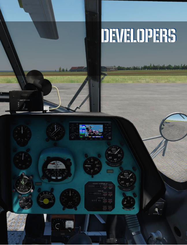
DCS [NS 430]
84 PAGES
BRG - Пеленг “НА”
DEVELOPERS DEVELOPERS

[NS 430] DCS
BELSIMTEK 85
Developers
BELSIMTEK
MANAGEMENT
Alexander Podvoisky Director, Belsimtek
Sergey Gerasev Producer, Documentation
Alexander Babichev Project Manager
PROGRAMMERS
Yury Nekrasov Instrument systems programming
Yury Kochmarev
Vyacheslav Kosach
Instrument compatibility with DCS World
Missions
DESIGN AND AUDIO
Pavel Sidorov Instrument model
Nadezhda Babicheva Manual Layout
Matthias Techmanski
Jzan Lo
Localization
English Manual

DCS [NS 430]
86 Developers
IT AND CUSTOMER
SUPPORT
Konstantin “Const” Borovik System- and Webadministrator, Forums
Andrey Filin System- and Networkadministrator, Kundendienst
Konstantin “MotorEAST” Harin Customer Support
QUALITY CONTROL Valery "USSR_Rik" Khomenok Lead Tester
Ivan "Frogfoot" Makarov Tester
Alexander "BillyCrusher" Bilievsky Tester
Nikita "Nim" Opredelenkov Tester
Oleg "Dzen" Fedorenko Tester
LOCALIZATION DEPT. Alexei "Mode" Chistyakov Localization
TESTERS Apache600 Astronut Breezy Bond 42 Gospadin Gumar Laivynas Muffler ody81 Scudrunner Skete SLPAK Sport SuperSix2 Wolf5 nts!