user manual en · extinguishing agents: all known extinguishing agents can be used. escape routes:...
TRANSCRIPT

VAS 581 009
Operating instructions V2.00 05/18

Contents
VAS 581 009 operating instructions V2.00 05/18 All rights reserved. 1
Contents
SAFETY INSTRUCTIONS................................................................ 4
SAFETY INSTRUCTIONS FOR CARBON DIOXIDE CO2 (R744) ... 6
SAFETY INSTRUCTIONS FOR NITROGEN N2 .............................. 8
SAFETY INSTRUCTIONS FOR WORKING ON AIR CONDITIONING SYSTEM ............................................................. 10
GENERAL OBLIGATIONS OF THE PERSONNEL ...................... 12
WORKING ON/IN ELECTRICAL COMPONENTS ........................ 12
OPERATING AND AUXILIARY MATERIALS ............................... 12
GENERAL SAFETY INSTRUCTIONS ........................................... 13
1 GENERAL INFORMATION .................................................. 14
1.1 General information ...................................................................................... 14
1.2 Safety instructions ........................................................................................ 15
1.3 EC Declaration of Conformity / CE marking .................................................. 15
1.4 Acceptance report ......................................................................................... 16
1.5 Intended use ................................................................................................. 16
1.6 Other applicable documents ......................................................................... 16
1.7 Scope of application ..................................................................................... 16
1.8 Software licence ........................................................................................... 16
2 DESIGN ................................................................................ 17
2.1 Front view ..................................................................................................... 17
2.2 Side view, right ............................................................................................. 18
2.3 Rear view ...................................................................................................... 19
2.4 Quick connectors .......................................................................................... 20
2.5 Refrigerating agent cylinder CO2 (R744) ...................................................... 21
2.6 Controls ........................................................................................................ 23
2.7 User interface operation ............................................................................... 24
2.8 User prompts ................................................................................................ 25
2.9 Text and number inputs ................................................................................ 26
2.10 Overview of operating modes ....................................................................... 27
2.11 Scope of delivery .......................................................................................... 28
2.11.1 System delivery ........................................................................................ 28
2.11.2 Available accessories ............................................................................... 29

Contents
VAS 581 009 operating instructions V2.00 05/18 All rights reserved. 2
3 AUTOMATIC MODE "AIR CONDITIONING SERVICE" ...... 30
4 MANUAL MODE ................................................................... 33
4.1 Drain hose .................................................................................................... 35
4.2 Customer data .............................................................................................. 35
4.3 Draining ........................................................................................................ 36
4.4 Generating vacuum ...................................................................................... 37
4.5 Filling ............................................................................................................ 38
4.6 Pressurecheck .............................................................................................. 39
4.7 HP/LP pressure test ...................................................................................... 40
4.8 External pressure test ................................................................................... 41
5 SETTINGS ............................................................................ 43
5.1 Units ............................................................................................................. 43
5.2 Date and time ............................................................................................... 43
5.3 Firmware update ........................................................................................... 44
5.4 Workshop data.............................................................................................. 44
5.5 Balance sheet ............................................................................................... 44
5.6 Language ...................................................................................................... 44
5.7 Printout text size ........................................................................................... 45
6 MAINTENANCE .................................................................... 46
6.1 Maintenance schedule .................................................................................. 46
6.2 Regular maintenance .................................................................................... 48
6.2.1 Change vacuum pump oil ......................................................................... 48
6.2.2 Check oil level (vacuum pump oil) ............................................................ 51
6.2.3 Refrigerating agent cylinder CO2 (R744) .................................................. 51
6.2.4 Cylinder adapter ....................................................................................... 52
6.2.5 LP and HP filling hoses ............................................................................ 52
6.2.6 LP and HP quick connectors .................................................................... 53
6.2.7 Cylinder heater (heating band) ................................................................. 53
6.2.8 Inspect device .......................................................................................... 53
6.3 Ad-hoc maintenance, as required ................................................................. 54
6.3.1 Refrigerating agent cylinder CO2 (R744) ................................................. 54
6.3.2 Pressure zeroing ...................................................................................... 70
6.3.3 Oil/UV additive scales zeroing .................................................................. 71
6.3.4 Oil regeneration ........................................................................................ 72
6.3.5 Save logs .................................................................................................. 72
6.4 Add new printer paper .................................................................................. 73
6.5 Replacing fuses ............................................................................................ 74
6.6 Other maintenance information..................................................................... 75
6.6.1 System information ................................................................................... 75
6.6.2 Operating hours ........................................................................................ 75
6.6.3 Replacing quick connector seals .............................................................. 76
Contents
VAS 581 009 operating instructions V2.00 05/18 All rights reserved. 3
7 SERVICE .............................................................................. 81
8 OVERVIEW ........................................................................... 82
9 PLACING OUT OF / INTO SERVICE / STORAGE .............. 83
9.1 Taking out of service ..................................................................................... 83
9.1 Transport ...................................................................................................... 83
9.2 Storage ......................................................................................................... 83
9.3 Placing back into service .............................................................................. 83
10 ERROR TABLE / IN CASE OF ERROR .............................. 84
11 MAINTENANCE AND CARE ................................................ 88
11.1 Visual inspection ........................................................................................... 88
11.2 Cleaning ....................................................................................................... 88
12 TECHNICAL DATA: ............................................................. 89
13 ERROR REPORTING FAX ................................................... 90
14 INDEX ................................................................................... 92
Subject change. Therefore, no rights can be derived from the specifications, figures and descriptions in these instructions. Reprinting, reproduction or translation for third parties, in part or in whole, are not permitted without the written permission of Volkswagen AG/the manufacturer. Volkswagen AG / the manufacturer expressly reserves all rights under the German Copyright Act.
VOLKSWAGEN AG Publisher: AVL DiTEST GmbH KD-Werkstattausrüstung Alte Poststraße 156 D-38436 Wolfsburg A-8020 Graz AUSTRIA VAS 581 009/2 AVL ID No.: AT7913EN Rev. 02 ASE 581 009 00 000

Safety instructions
VAS 581 009 operating instructions V2.00 05/18 All rights reserved. 4
SAFETY INSTRUCTIONS Sign and symbols
Symbols with the following meanings are used in the safety instructions of the operating instructions, unpacking instructions or other supplied instructions as well as on the display of the tester during operation and on the products themselves:
DANGER
Indicates an extreme danger that can lead to death if not avoided.
WARNING
Indicates an imminent danger that can lead to death or severe injury if not avoided.
CAUTION
Indicates a danger that can lead to moderate or minor injuries.
Prohibition signs
Fire and open flames
prohibited
Warning signs
General Risk of electric shock
Hazardous gases
Warning of gas cylinders
Danger of suffocation

Safety instructions
VAS 581 009 operating instructions V2.00 05/18 All rights reserved. 5
Mandatory signs
Wear protective goggles
Wear gloves Refrigerating agent cylinder
Secure CO2 (R744)
Wear protective
shoes
Wear respiratory protection
Wear protective clothing
Other symbols
Observe operating
instructions
Fuse First aid Gas cylinder
Notices:
NOTICE
This text points to situations or mal operations that can lead to damage or data loss.
Information
This text indicates important information or instructions. Failure to comply with these instructions will prevent or significantly hinder the successful implementation of the actions described in this documentation.

Safety instructions
VAS 581 009 operating instructions V2.00 05/18 All rights reserved. 6
SAFETY INSTRUCTIONS FOR CARBON DIOXIDE CO2 (R744)
Always observe the manufacturer's safety data sheet!
WARNING
Contact with the product can cause cold burns or frostbite. Gases/vapours are heavier than air. High concentration due to accumulation in closed rooms, work pits, cellars, etc. can cause asphyxiation, among other things. Symptoms: Loss of motor ability and consciousness. Affected persons do not realise that they are suffocating. Do not allow carbon monoxide to enter sewage systems, pits or similar enclosures where gas accumulation may be dangerous.
Precautions and behaviour rules
WARNING
Storage: Store container in a well-ventilated place at a temperature below 50 °C. Protect container against impacts and falls (secure with chain).
Handling: Avoid contact with eyes and skin. Do not inhale the gas. Ensure that no water enters the gas cylinder/container. Prevent the gas from flowing back into the gas tank. Only use equipment that is suitable for this product and the intended pressure and temperature. Check fittings, connections and lines for leaks. Eating, drinking and storing food in the working area are prohibited.
Respiratory protection: Self-contained breathing apparatus.
Eye protection: Tightly fitting protective goggles.
Hand protection: Protective gloves (material: leather).
Body protection: Protective clothing.

Safety instructions
VAS 581 009 operating instructions V2.00 05/18 All rights reserved. 7
Behaviour in the event of danger
After a gas leak: Keep unprotected persons away. Ventilate rooms well. Wear protective gear and self-contained breathing apparatus. Close valves / stop gas leak. Avoid entry into cellars, pits and similar enclosures (danger of suffocation).
In case of fire: Wear protective gear and self-contained breathing apparatus. Stop gas leak if possible. Cool cylinders with a water jet from a secure position and remove them from the fire zone if possible to prevent explosion! The product itself is non-flammable.
Extinguishing agents: All known extinguishing agents can be used. Escape routes: Escape routes must be known to staff. Accident phone: The accident phone must be known to staff.
First aid
Please observe the instructions for use and safety of your refrigerant supplier.

Safety instructions
VAS 581 009 operating instructions V2.00 05/18 All rights reserved. 8
SAFETY INSTRUCTIONS FOR NITROGEN N2
Always observe the manufacturer's safety data sheet!
WARNING
High concentrations of the gas can cause suffocation. Loss of motor ability and consciousness. Rapid release of large quantities creates cold and fog. Gas may accumulate in cellars, pits, etc., because it is about as heavy as air. Container may burst or explode in the event of a fire.
Precautions and behaviour rules
WARNING
Employees must be instructed in the use of the gas before being allowed to work with it. Do not inhale cylinder gas. Secure cylinders from falling over. Ensure good ventilation when working. Filter masks do not protect against asphyxiation! Wear protective gloves when transporting the cylinder. Use the cylinder trolley. Never open valves forcibly (no pliers, etc.) Store cylinder in well-ventilated location at a temperature <50 °C. Only use suitable equipment (pressure/temperature/product). Ensure that no water can enter or flow back into the gas cylinder. Always close cylinders, even if they are empty, before transporting them and secure with lock not and protective cap. Lash down cylinders when transporting them in a vehicle. The loading space should be separate from the driver's cab and have vents in the ceiling and floor areas.

Safety instructions
VAS 581 009 operating instructions V2.00 05/18 All rights reserved. 9
Behaviour in the event of danger
WARNING
Exposure to heat and fire may cause cylinders to burst/explode. All extinguishing agents can be used. If gas is escaping, close valve is possible. Make sure that the gas does not enter cellars, recesses, pits, etc. where gas accumulation might be dangerous (danger of suffocation). Fire: Remove container from the danger zone or, if this is not possible, cool it with water from a safe distance. Ensure good ventilation. In case a large quantity is released or in confined spaces: Evacuate area and enter only with self-contained breathing apparatus. Re-entry only after verification of safe level.
First aid
Please observe the instructions for use and safety of your refrigerant supplier.

Safety instructions
VAS 581 009 operating instructions V2.00 05/18 All rights reserved. 10
SAFETY INSTRUCTIONS FOR WORKING ON AIR CONDITIONING SYSTEM
WARNING
The device must not be used if the heating band or cable is damaged. Contact the respective AVL DiTEST branch / AVL DiTEST partner in your country!
NOTICE
The oil level of the vacuum pump must be checked regularly. Top up if necessary. After 60 operating hours a regeneration of the pump oil is necessary (user notification). The regeneration can be performed from the maintenance menu. After 500 operating hours or one year, the pump oil must be changed (user notification). Oil changes can also be performed via the maintenance menu. The pump oil will also be changed as part of the annual servicing of the device by the service partner.
NOTICE
A device check is performed automatically once a week. It can also be triggered manually in the maintenance menu. The device check ensures that the system is sealed and all components are operating correctly. In case of a malfunction, the device will have to be serviced.
NOTICE
The filling levels of the oil/additive containers must be checked at regular intervals. Full used-oil containers must be emptied. Empty clean-oil and UV contrast medium bottles must be refilled if necessary.

Safety instructions
VAS 581 009 operating instructions V2.00 05/18 All rights reserved. 11
NOTICE
Check the available printer paper and replace the paper roll if necessary.
NOTICE
We recommend that you have the device serviced by your service partner once a year. As part of every servicing the vacuum pump oil is changed and the calibration checked. If necessary, a recalibration is performed.
NOTICE
The VAS 581 009 may only be operated on a level and solid foundation. The refrigerating agent cylinder must be upright in the device. Any tilting may result in incorrect measurements by the cylinder scales and thus incorrect filling quantities!
NOTICE
Open the manual valve of the connected refrigerating agent cylinder before switching on. If the VAS 581 009 is not being used, shut of the gas supply by closing the manual valve.
NOTICE
The VAS 581 009 performs a self-test when it is switched on. This is indicated by the brief sounding of the siren.
NOTICE
If the VAS 581 009 is not used for a prolonged period, the manual valve must be closed.

Safety instructions
VAS 581 009 operating instructions V2.00 05/18 All rights reserved. 12
GENERAL OBLIGATIONS OF THE PERSONNEL
WORKING ON/IN ELECTRICAL COMPONENTS
Before working on electrical components, the following minimum requirements must be observed:
1. Make sure that the system is fully de-energized
2. Secure against accidental re-activation
3. Check de-energized state
4. Earth and short
5. Cover adjacent live parts.
After the work has been carried out, perform these five steps in reverse order.
OPERATING AND AUXILIARY MATERIALS
Before using operating and auxiliary materials, the material safety data sheets for the
product and the manufacturer's instructions must be read.
An appropriate safety concept must be developed and adhered to based on these material safety data sheets.

Safety instructions
VAS 581 009 operating instructions V2.00 05/18 All rights reserved. 13
GENERAL SAFETY INSTRUCTIONS
WARNING
Read all instructions carefully!
DANGER
Danger of life due to electrical voltage
The cylinder heater is operated via the mains voltage! Only connect/disconnect the VAS 581 009 when it is switched off.
CAUTION
The weight can result in persons or body parts being trapped. Ensure wheel brakes are applied during operation. Ensure that there is a minimum distance of 1.5 m to walls.
KEEP THESE INSTRUCTIONS IN A SAFE PLACE!

General information
VAS 581 009 operating instructions V2.00 05/18 All rights reserved. 14
1 General information
1.1 General information
The VAS 581 009 is intended for filling vehicle air conditioning systems with CO2 (R 744).
The VAS 581 009 is intended for repair/service workshops or similar institutions. It is intended solely for professionals who are familiar with the basic concepts of cooling, cooling systems, the refrigerating agent and the relevant regulations for pressure equipment and the damage it may cause. Observe the regulations in force in your country! Read and observe these operating instructions, especially the safety instructions. The VAS 581 009 was subjected to extensive tests before it was placed into service and must be checked at regular intervals (in accordance with the relevant laws and regulations in force in the country) while in use. It is the responsibility of the user to ensure that the air conditioning system is used in accordance with the national regulation in force.
Fig. 1-1

General information
VAS 581 009 operating instructions V2.00 05/18 All rights reserved. 15
1.2 Safety instructions
Observe the safety instructions for the VAS 581 009. They can be found below the table of contents.
1.3 EC Declaration of Conformity / CE marking
The manufacturer hereby declares that the VAS 581 009 is in conformity with the provisions of the following EC directives, including all applicable amendments. 2014/30/EU Directive of the European Parliament and of the Council on the harmonisation of the laws of the Member States relating to electromagnetic compatibility 2014/35/EU Directive of the European Parliament and of the Council on the harmonisation of the laws of the Member States relating to the making available on the market of electrical equipment designed for use within certain voltage limits
The VAS 581 009 is in conformity with:
SAFETY:
EN 61326-1:2013 IEC 61010-1:2010

General information
VAS 581 009 operating instructions V2.00 05/18 All rights reserved. 16
1.4 Acceptance report
A device-specific acceptance report is included in the delivery.
1.5 Intended use
The VAS 581 009 may only be used as prescribed in the operating instructions.
The described product has been developed, manufactured, tested and documented, taking into account the relevant safety standards. When observing the safety and prescribed placing into service instructions, using the device as intended and maintaining it as recommended, the VAS 581 009 normally does not pose a risk to property or health.
1.6 Other applicable documents
In addition to these operating instructions, the following other technical documents pertaining to the VAS 581 009 exist:
unpacking and placing into service instructions, quick start guide VAS 581 009
1.7 Scope of application
The VAS 581 009 is intended for filling vehicle air conditioning systems with CO2 (R 744).
1.8 Software licence
The software licence is available here: https://www.avlditest.com/index.php/de/ads-310-830.html

Design
VAS 581 009 operating instructions V2.00 05/18 All rights reserved. 17
2 Design
2.1 Front view
Fig. 2-1
1 Display
2 Multi-functional dial
3 Hand rail
4 Printer
5 Wheel brakes
1
2
1
3
1
4
1
5
2
1
1

Design
VAS 581 009 operating instructions V2.00 05/18 All rights reserved. 18
2.2 Side view, right
Fig. 2-2
1 Extractable collection container for drained vacuum pump oil
2 Socket screw for draining the vacuum pump oil
3 Gauge glass for vacuum pump oil
1
3
2

Design
VAS 581 009 operating instructions V2.00 05/18 All rights reserved. 19
2.3 Rear view
Fig. 2-3
1 Chain for securing the carbon dioxide CO2 (R744) refrigerating agent cylinder
2 Container for clean oil 250 ml
3 Container for UV additive 250 ml
4 Container for used oil 250 ml
5 Quick connector HP red
6 Connection VAS 584 003, tightening torque 16 ... 18 Nm
7 USB port cover
8 Mains switch with fuse link
9 Quick connector LP blue
2
3
1
4
6
7
8
5
9

Design
VAS 581 009 operating instructions V2.00 05/18 All rights reserved. 20
2.4 Quick connectors
Your VAS 581 009 is equipped with a quick connector system.
These connectors offer the following safety features:
No mechanical disconnection of connectors while under pressure.
The connectors are self-ventilating.
WARNING
The quick connectors may only be unscrewed by authorised personnel!
Fig. 2-4

Design
VAS 581 009 operating instructions V2.00 05/18 All rights reserved. 21
2.5 Refrigerating agent cylinder CO2 (R744)
Fig. 2-5 Example
NOTICE
The VAS 581 009 is suitable for standard CO2 (R744) refrigerating agent cylinders with a built-in riser tube. The following cylinder sizes can be used: 5 kg, 6 kg, 10 kg or 20 kg. Required purity equal or better than carbon dioxide 3.0 (99.9 % purity).
WARNING
Frostbites caused by refrigerating agent Cylinders may only be replaced by professional staff. Follow step-by-step instructions on VAS 581 009.
CAUTION
Injuries to body parts.
Depending on the size, cylinders can weigh up to 50 kilograms. Load the cylinder onto the VAS 581 009 with the help of another person.

Design
VAS 581 009 operating instructions V2.00 05/18 All rights reserved. 22
NOTICE
Only use the VAS 581 009 if the filling hoses are correctly connected. Filling with incorrectly connected hoses will damage the VAS 581 009.
NOTICE
The VAS 581 009 is supplied with a CO2 (R744) refrigerating agent cylinder.
Definition: Quick connector "screwed in" / "screwed out"
Screwed in: Screwed out:
Screwed clockwise screwed counter clockwise
Valve open Valve closed
Fig. 2-6 Fig. 2-7

Design
VAS 581 009 operating instructions V2.00 05/18 All rights reserved. 23
2.6 Controls
Fig. 2-8
1 Mains switch
2 Adjustable display
3 Multi-functional dial
2
3
1

Design
VAS 581 009 operating instructions V2.00 05/18 All rights reserved. 24
2.7 User interface operation
The user interface is controlled via a multi-functional dial. The individual functions (buttons) are selected by turning the dial. To start a function, the dial must be pressed.
Fig. 2-9
HP High Pressure High pressure HP display of the refrigerating agent circuit
LP Low Pressure Low pressure LP display of the refrigerating agent circuit
Multi-functional dial To select and start a function
Operating modes
Automatic mode Sec. 3 "Automatic mode"
Manuel mode Sec. 4 "Manuel mode"
Settings Sec. 5 "Settings"
Maintenance Sec. 6 "Maintenance"
Service Sec. 7 "Service"
Overview Sec. 8 „Overview“
1
2
3
4
4 1 2 3

Design
VAS 581 009 operating instructions V2.00 05/18 All rights reserved. 25
2.8 User prompts
Up Selects previous function
Down Selects the next function.
Back Goes back one step.
Start Starts functions.
Cancel Cancels an ongoing operation. Confirms questions with "No".
RESET Resets values.
OK Confirms questions with "Yes" or "OK".
Next Continues to the next step.
Print Prints logs.
RESET

Design
VAS 581 009 operating instructions V2.00 05/18 All rights reserved. 26
2.9 Text and number inputs
If a number or letter is expected as an input, turning the dial will show the letters and numbers in sequential order. Pressing the dial will select the letter or number.
Fig. 2-10 Example input
The multi-functional dial is equipped with an indicator.
Meaning of the indicator:
Meaning Indicator state
System start Blue
Status OK / completed Green
Ongoing process Yellow
User information Yellow flashing (1-2 Hz)
Error Red flashing (1-2 Hz)
System error Red fast flashing (10 Hz)

Design
VAS 581 009 operating instructions V2.00 05/18 All rights reserved. 27
2.10 Overview of operating modes
Operating mode Function Explanation
Automatic cycle Automatic cycle:
1. Preparing device 2. Draining 3. Generating vacuum 4. Pressure test (if activated) 5. Filling
See Sec. 3
Manual cycle Drain hose See Sec. 4.1
Draining See Sec. 4.3
Generating vacuum See Sec. 4.4
Filling See Sec. 4.5
Pressure test See Sec. 4.6
HP/LP pressure test See Sec. 4.7
External pressure test See Sec. 4.8
Settings Units See Sec. 5.1
Date/time See Sec. 5.2
Firmware update See Sec. 5.3
Workshop data See Sec. 5.4
Balance sheet See Sec. 5.5
Language See Sec. 5.6
Printout text size See Sec. 5.7
Maintenance System info See Sec. 6.6.1
Operating hours See Sec. 6.6.2
Vacuum pump oil See Sec. 6.2.1
Cylinder replacement See Sec. 6.3.1
Pressure zeroing See Sec. 6.3.2
Oil//UV/additive scales zeroing See Sec. 6.3.3
Device check See Sec. 6.2.8
Save logs See Sec. 6.3.5
Service
Password-protected
Only for authorised service staff
---
Overview
Display of status information See Sec. 8

Design
VAS 581 009 operating instructions V2.00 05/18 All rights reserved. 28
2.11 Scope of delivery
2.11.1 System delivery
No.
VAS No. Components Item number
AVL DiTEST
VOLKSWAGEN
1. VAS 581 009 Basic device VAS 581 009 cplt.
VS9155 ASE 581 009 00 000
2. Operating instructions on CD BO7960
3. Unpacking instructions, placing into service instructions, quick start guide, printed
AT7912EN
4. Inspection log book, printed AT7914EN
5. Quick connector CO2 HP red GE7520
6. Quick connector CO2 LP blue GE7522
7. Filling hose CO2 HP red SS7520
8. Filling hose CO2 LP blue SS7521
9. Cover MK7532
10. Acceptance report
11. Cylinder adapter W21.8x1/14“ incl. seal for connecting R744 cylinder to the VAS 581 009 Notice: It is possible that the supplied cylinder adapter is not compatible with a cylinder available in your country. This is why we offer a variety of different adapters. See "Available accessories".
DN7469
12. Protective goggles GE7432
13. Protective gloves GE7435
14. Cylinder adapter seal DA7451
15. Printing paper HP7003
16. Power cable EU EX7075
17. Heating tape BV8313

Design
VAS 581 009 operating instructions V2.00 05/18 All rights reserved. 29
2.11.2 Available accessories
No.
VAS No. Components Item number
AVL DiTEST VOLKSWAGEN
18. Vacuum pump oil 500 ml (2 units per package)
GE7427
19. Printer paper 57 mm, (minimum order quantity: 5 units
HP7003
20. Cylinder heater (heating band) incl. connector
BV8313
21. External pressure test set BO7948 VAS 584 003
22. Cylinder adapter incl. seal: W21.7x1/14"
DN7470
23. Cylinder adapter incl. seal: 0.860"x14TPI
DN7471
24. Cylinder adapter incl. seal: G3/4"
DN7472
25. Cylinder adapter incl. seal: 0.825"x14NGO
DN7473
26. Cylinder adapter incl. seal: W27x2 mm
DN7474
27. Calibration kit VAS 581 009 BO7972
WARNING
Only use accessories approved by AVL DiTEST!

Automatic cycle
VAS 581 009 operating instructions V2.00 05/18 All rights reserved. 30
3 Automatic mode "Air conditioning service"
There are a max. of three pre-set configurations available There are all based on different default values. The default values can be applied or changed. Changes to default values are automatically saved in the configuration. Select Automatic cycle in the main menu.
Fig. 3-1 The following functions are performed during the automatic cycle:
1. Preparing device 2. Draining 3. Generating vacuum 4. Pressure test (if activated) 5. Filling
Default values:
Button Parameter Unit Selection
Configuration name
Refrigerating agent quantity
g 0 … 1500
Oil quantity g 0 … 20
Oil filling mode* REC+/ABS/NO
UV additive quantity g 0 … 20
Vacuum time min 5 … 60
Vacuum test time min 5 … 120
Connection type LP / HP+LP
Pressure test OFF / 10 % / 75 g / 20 % / 75 g / 100 g / 150 g /200 g / 250 g / 300 g

Automatic cycle
VAS 581 009 operating instructions V2.00 05/18 All rights reserved. 31
Pressure test time min 1 … 30
Pressure loss mbar 100 … 1000
Customer data
*Oil filling mode: NO: No oil is pumped into the air conditioning system of the vehicle. The set oil quantity is ignored. ABS: The set quantity of oil is pumped into the air conditioning system of the vehicle.
REC+: Depending on the quantity of used oil recovered, this quantity of oil plus the set quantity of oil is pumped into the air conditioning system of the vehicle. For example: Recovered oil quantity = 8 grams used oil, set oil quantity= 10 grams, -> 18 grams of oil are pumped into the vehicle Check the inputs and confirm with . The automatic cycle starts. Follow the instructions on the screen. The steps Preparing device, Draining, Generating vacuum, Pressure test(if enabled) and Filling are performed automatically. Take note of the messages on the screen and follow the instructions. Take note of the colour of the illuminated multi-functional dial, see Sec. 2.6. Upon completion of the automatic cycle, you can print all results with .
Automatic cycle
VAS 581 009 operating instructions V2.00 05/18 All rights reserved. 32
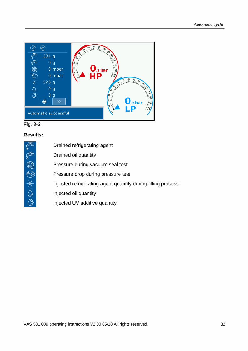
Fig. 3-2
Results:
Drained refrigerating agent
Drained oil quantity
Pressure during vacuum seal test
Pressure drop during pressure test
Injected refrigerating agent quantity during filling process
Injected oil quantity
Injected UV additive quantity

Manual cycle
VAS 581 009 operating instructions V2.00 05/18 All rights reserved. 33
4 Manual mode
NOTICE
Only connect the quick connectors to the air conditioning system of the vehicle once indicated by the VAS 581 009 on the display.
Fig. 4-1
During a manual cycle, the following functions can be started and executed separately.
Drain hose The filling hoses are completely emptied. To do so, disconnect the filling hoses from the vehicle.
Customer data: To log the following processes, customer data can be retrieved from the database
Draining This function drains the CO2 refrigerating agent from the vehicle in a controlled manner. The sub-function Oil separation takes place at the same time. Oil separation: The oil quantity drained out of the air conditioning system is transported away. The quantity of used oil is weighed and saved for logging purposes.
Generating vacuum
A vacuum is generated inside the air conditioning system. This reveals any leaks inside the air conditioning system of the vehicle.

Manual cycle
VAS 581 009 operating instructions V2.00 05/18 All rights reserved. 34
Filling This process compensates the oil quantity removed during draining with clean oil according to the selected settings. Then the air conditioning system of the vehicle is filled with the refrigerating agent CO2 (R744).
Pressure test With this function, the vehicle's air conditioning system is filled with a set quantity of 70 to 300 grams of refrigerating agent. The pressure loss over the selected time period is determined. This reveals any leaks inside the air conditioning system of the vehicle.
HP/LP pressure test
With this function, the pressure of the vehicle's air conditioning system while in operation is measured and displayed.
External pressure test
With this function, a pressure of 90 to 100 bar is applied to the vehicle's air conditioning system from a nitrogen cylinder. The pressure loss over the selected time period is determined.

Manual cycle
VAS 581 009 operating instructions V2.00 05/18 All rights reserved. 35
4.1 Drain hose
Select Manual│Drain hose in the main menu. With the "Drain hose" function you can completely drain the external filling hoses.
4.2 Customer data
For all selectable processes (except for "Drain hose"), customer data can be entered for logging purposes.
Fig. 4-2
Manual cycle
VAS 581 009 operating instructions V2.00 05/18 All rights reserved. 36
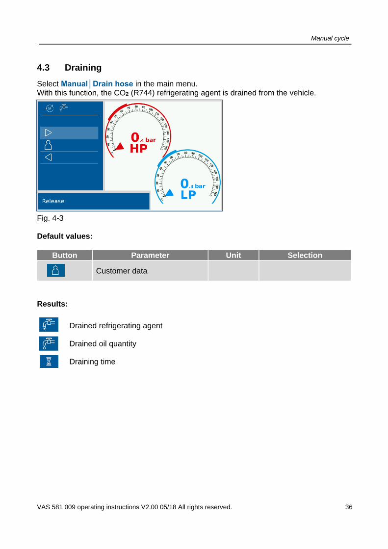
4.3 Draining
Select Manual│Drain hose in the main menu. With this function, the CO2 (R744) refrigerating agent is drained from the vehicle.
Fig. 4-3 Default values:
Button Parameter Unit Selection
Customer data
Results:
Drained refrigerating agent Drained oil quantity Draining time

Manual cycle
VAS 581 009 operating instructions V2.00 05/18 All rights reserved. 37
4.4 Generating vacuum
Select Manual│Vacuum in the main menu. A vacuum is generated inside the air conditioning system. This reveals any leaks inside the air conditioning system of the vehicle.
Fig. 4-4
Default values:
Button Parameter Unit Selection
Vacuum time min 5 … 60
Vacuum test time min 5 … 120
Customer data
Results:
Vacuum pressure minimum value
Pressure increase
Number of repetitions
Vacuum test time
Vacuum test evaluation ok/not ok only on printout! Note:
If vacuum is used to check for leaks inside the device (no air conditioning system connected), we recommend you set the vacuum time to at least 60 minutes. After effects of the refrigerating agent CO2 may result in the misinterpretation of the result due to too excessive pressure increase.

Manual cycle
VAS 581 009 operating instructions V2.00 05/18 All rights reserved. 38
4.5 Filling
Select Manual│Filling in the main menu. In the first step, the set oil and UV additive quantities are injected into the air conditioning system of the vehicle. Then it is filled with the set quantity of refrigerating agent CO2 (R744).
Fig. 4-5 Default values:
Button Parameter Unit Selection
Refrigerating agent quantity CO2 (R744)
g 0 … 1500
Oil quantity g 0 … 20
UV additive g 0 … 20
Connection type LP / HP+LP
Pressure test OFF / 10 % /75 g / 20 % /75 g
Duration of pressure test min 1 … 30
Pressure loss mbar 100 … 1000
Customer data
Results: Injected quantity of refrigerating agent Injected oil quantity Injected UV additive quantity

Manual cycle
VAS 581 009 operating instructions V2.00 05/18 All rights reserved. 39
4.6 Pressurecheck
Select Manual│Pressure test in the main menu. The air conditioning system of the vehicle is applied with a preset quantity of refrigerating agent. After a stabilisation period, the pressure change can be determined based on the set length of the test. The actual pressure loss is determined and compared with the set max. permissible pressure loss. Fig. 4-6 Default values:
Button Parameter Unit Selection
Refrigerating agent quantity
g 70 … 300
Duration of pressure test min 1 … 30
Pressure loss mbar/min 100 … 1000
Customer data
Results: Injected quantity of refrigerating agent Pressure at the end of the injection process Pressure loss during pressure test
Manual cycle
VAS 581 009 operating instructions V2.00 05/18 All rights reserved. 40
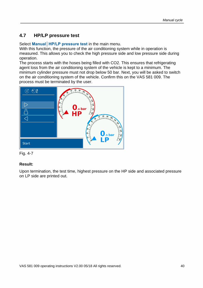
4.7 HP/LP pressure test
Select Manual│HP/LP pressure test in the main menu. With this function, the pressure of the air conditioning system while in operation is measured. This allows you to check the high pressure side and low pressure side during operation. The process starts with the hoses being filled with CO2. This ensures that refrigerating agent loss from the air conditioning system of the vehicle is kept to a minimum. The minimum cylinder pressure must not drop below 50 bar. Next, you will be asked to switch on the air conditioning system of the vehicle. Confirm this on the VAS 581 009. The process must be terminated by the user.
Fig. 4-7
Result:
Upon termination, the test time, highest pressure on the HP side and associated pressure on LP side are printed out.

Manual cycle
VAS 581 009 operating instructions V2.00 05/18 All rights reserved. 41
4.8 External pressure test
With the external pressure test, the air conditioner can be tested for leaks with a pressure of 99 ... 101 bar. This requires a nitrogen cylinder and the external pressure test set VAS 584 003 (AVL ID No. BO7948). Note the ext. Pressure test set enclosed Quickstart, AVL ID no. 7948. Select Manual│External pressure test in the main menu.
Fig. 4-8
Default values:
Button Parameter Unit Selection
Save log data On / Off
customer data
Start the external pressure test with .
Follow the instructions on the screen in detail.
Process overview:
a) Close manual valve on the refrigerant bottle. b) Connect couplings to the vehicle, screw in fittings. c) Connect nitrogen bottle N2. VAS 584 003 - Note quickstart.
Torque max. 18 Nm 30 ... 32 Nm max. 18 Nm

Manual cycle
VAS 581 009 operating instructions V2.00 05/18 All rights reserved. 42
d) Set test pressure of 14 ... 15 bar. To do this, slowly open the manual valve on the VA 584 003. It is measured 2 times for 1 minute each time and the pressure (HP and LP) is displayed.
e) Options: Cancel Uncouple Repeat Continue
f) Select Continue. g) Set test pressure of 99 ... 101 bar.
To do this, open the manual valve on the VA 584 003. External pressure test is carried out. The pressure (HP and LP) is displayed.
h) Options: Cancel Uncouple Repeat
i) Exit ext. pressure check with uncoupling.

Settings
VAS 581 009 operating instructions V2.00 05/18 All rights reserved. 43
5 Settings
Under the "Settings" menu item you can change various parameters and enable various features.
Fig. 5-1
Select the desired function. Follow the instructions on the screen.
5.1 Units
With this function, you can select the units for pressure (bar/psi), temperature (°C/°F) and oil quantities (g/ml).
5.2 Date and time
Here you can enter/change the date and time. You can also select a country-specific date/time format, e.g. USA.

Settings
VAS 581 009 operating instructions V2.00 05/18 All rights reserved. 44
5.3 Firmware update
Here you can update the firmware of the VAS 581 009.
1. Remove the cover on the right side (below the mains switch) and plug in the USB
stick containing the firmware.
Fig. 5-2
2. Select Settings│Firmware update in the main menu.
3. Confirm with .
4. The firmware update starts automatically.
5. Follow the instructions on the screen of the VAS 581 009.
WARNING
During the firmware update, you may hear the sired for up to two minutes. The VAS 581 009 must not be disconnected from the power supply during this time.
The VAS 581 009 restarts and performs a self-test after a language has been selected.
5.4 Workshop data
Here you can enter/change workshop data (company, address, e-mail, telephone number).
5.5 Balance sheet
The balance sheet provides for a key date evaluation of the discharged refrigerating agent and recovered oil as well as the refrigerating agent and clean oil that has been topped up. The evaluation is shown under this menu item and can be printed or reset.
5.6 Language
Here you can select the language. Once selected, the VAS 581 009 restarts.

Settings
VAS 581 009 operating instructions V2.00 05/18 All rights reserved. 45
5.7 Printout text size
Here you can choose between small, medium and large front for the printout.
Information
AVL DiTEST reserves the right to add new parameters to make the VAS 581 009 even more versatile and adapt it to market requirements.

Maintenance
VAS 581 009 operating instructions V2.00 05/18 All rights reserved. 46
6 Maintenance
6.1 Maintenance schedule
To ensure faultless operation, the VAS 581 009 must be serviced at regular intervals. All maintenance work that has been carried out must be recorded in the inspection log.
If necessary, e.g. in case of problems, additional maintenance work can be carried out or information retrieved.
Component/assembly/function Interval Explanation
Regular maintenance
Change vacuum pump oil Every 500 operating hours or at least once a year
Sec. 6.2.1
Check oil level (vacuum pump oil) Weekly Sec. 6.2.2
Check CO2 (R744) refrigerating agent Weekly Sec. 6.2.3
Check cylinder adapter Weekly Sec. 6.2.4
Check LP and HP hoses Weekly Sec. 6.2.5
Check quick connectors Weekly Sec. 6.2.6
Check cylinder heater (heating band) while switched off
Daily Sec. 6.2.7
Inspect device Weekly Sec. 6.2.8
Ad-hoc maintenance (as required)
Cylinder replacement As required Sec. 6.3.1
Pressure zeroing As required Sec. 6.3.2
Oil/UV additive scales zeroing As required Sec. 6.3.3
Oil regeneration As required Sec. 6.3.4
Save logs As required Sec. 6.3.5
Printer Add new printer paper As required Sec. 6.4
Fuse Replace fuse As required Sec. 6.5
Other maintenance information
System info --- Sec. 6.6.1
Operating hours --- Sec. 6.6.2
Replace seals --- Sec. 6.6.3

Maintenance
VAS 581 009 operating instructions V2.00 05/18 All rights reserved. 47
WARNING
Danger to life from electric current Make sure that the VAS 581 009 is disconnected from the power supply before opening it!
WARNING
Do not make any modifications to the VAS 581 009 that are not explicitly specified in this chapter.
WARNING
Only use original AVL DiTEST spare parts!

Maintenance
VAS 581 009 operating instructions V2.00 05/18 All rights reserved. 48
6.2 Regular maintenance
6.2.1 Change vacuum pump oil
Change the vacuum pump oil after 500 operating hours (at least once a year). The VAS 581 009 will inform you when the vacuum pump oil needs changing.
1. Select Maintenance│Vacuum pump oil.
2. This display will show: - Time since last oil regeneration - Remaining time until next oil regeneration - Time since last oil change - Remaining time until next oil change - Start regeneration of vacuum pump oil - Reset vacuum pump oil meter (when changing vacuum pump oil)
3. Switch the VAS 581 009 off and pull the power plug.
4. Unscrew the socket screw to train the oil (a). The oil drains into the extractable oil container (b).
Fig. 6-1
5. Screw the socket screw back in again (a). 6. Empty the oil container (b).
b
a

Maintenance
VAS 581 009 operating instructions V2.00 05/18 All rights reserved. 49
7. Remove the housing. To do so, unscrew the two screws (c), pull the housing (d) slightly outwards and then press it forwards.
Fig. 6-2
8. Unscrew the cap (e) and fill in the oil; fill quantity 250 ml Only use the vacuum pump oil specified in the2.11.2 "Available accessories" section. Screw the cap (e) back on again.
Fig. 6-3
9. Check the oil level (f) through the gauge glass.
Fig. 6-4
f
c
d
e

Maintenance
VAS 581 009 operating instructions V2.00 05/18 All rights reserved. 50
10. Re-attach the housing (d), see Item 7. Make sure that the three white studs snap into the black plastic parts before screwing the housing back on.
Fig. 6-5
11. Switch the device off again. Navigate to Maintenance│Vacuum pump oil│Reset vacuum pump oil meter. This will reset the values shown under Item 2.

Maintenance
VAS 581 009 operating instructions V2.00 05/18 All rights reserved. 51
6.2.2 Check oil level (vacuum pump oil)
Check the oil level through the gauge glass weekly. Top up or change the vacuum pump oil if necessary, see Sec. 6.2.1.
Fig. 6-6
6.2.3 Refrigerating agent cylinder CO2 (R744)
Check the refrigerating cylinder weekly for corrosion, leaks and damage.
Under normal operating conditions, the device has a service life of at least 20 years (provided there is no wear or other damage).
Fig. 6-7
Maintenance
VAS 581 009 operating instructions V2.00 05/18 All rights reserved. 52
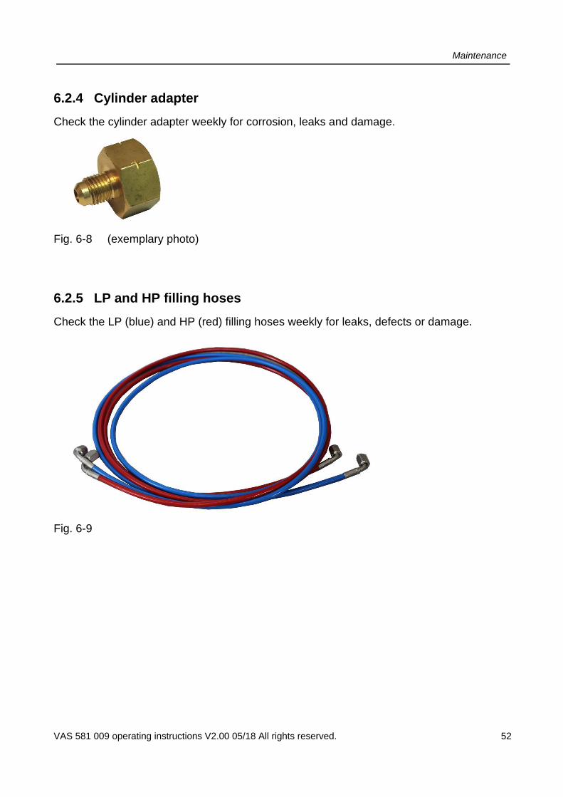
6.2.4 Cylinder adapter
Check the cylinder adapter weekly for corrosion, leaks and damage.
Fig. 6-8 (exemplary photo)
6.2.5 LP and HP filling hoses
Check the LP (blue) and HP (red) filling hoses weekly for leaks, defects or damage.
Fig. 6-9

Maintenance
VAS 581 009 operating instructions V2.00 05/18 All rights reserved. 53
6.2.6 LP and HP quick connectors
Check the LP (blue) and HP (red) quick connectors weekly for leaks, defects or damage.
Fig. 6-10
6.2.7 Cylinder heater (heating band)
WARNING
Only check cylinder heater (heating band) when it is switched off! The device must not be used if the heating band or cable is damaged. Contact the respective AVL DiTEST branch / AVL DiTEST partner in your country!
Check the cylinder heating / cables daily for defects or damage.
Make sure that the cylinder heating is connected correctly.
Fig. 6-11
6.2.8 Inspect device
Performs an internal self-test by switching on all valves and checking the system for leaks. This self-test must be performed every seven days.

Maintenance
VAS 581 009 operating instructions V2.00 05/18 All rights reserved. 54
6.3 Ad-hoc maintenance, as required
6.3.1 Refrigerating agent cylinder CO2 (R744)
Proceed as follows:
1. Switch on the VAS 581 009.
2. The following message appears after a successful self-test.
Fig. 6-12
3. Continue with .
4. You are in the main menu. Tap Maintenance.
Fig. 6-13

Maintenance
VAS 581 009 operating instructions V2.00 05/18 All rights reserved. 55
5. Select Replace refrigerating agent cylinder in the maintenance menu.
Fig. 6-14
6. Now select Cylinder content.
Fig. 6-15

Maintenance
VAS 581 009 operating instructions V2.00 05/18 All rights reserved. 56
7. Enter the weight of the cylinder content. (= nominal quantity of the content / nominal capacity of the cylinder, not the actual cylinder capacity!). Incorrect entries inevitably result in incorrect calculations of the available/usable cylinder capacity.
Fig. 6-16
8. Select tare weight.
Fig. 6-17

Maintenance
VAS 581 009 operating instructions V2.00 05/18 All rights reserved. 57
9. Refrigerating agent cylinder with protective cap: a) In order to read the tare weight, the protective cap must be removed from the
refrigerating agent cylinder
Fig. 6-18
b) Note down the tare weight. The tare weight represents the net weight of the used cylinder (empty). This weight is usually shown on the cylinder, sometimes embossed.
Fig. 6-19

Maintenance
VAS 581 009 operating instructions V2.00 05/18 All rights reserved. 58
a) Mark the location of the outlet valve on the refrigerating agent cylinder.
Fig. 6-20
b) Re-attach the protective cap.
Fig. 6-21

Maintenance
VAS 581 009 operating instructions V2.00 05/18 All rights reserved. 59
10. Enter the tare weight.
Fig. 6-22
11. Press to continue replacing the cylinder.
Fig. 6-23

Maintenance
VAS 581 009 operating instructions V2.00 05/18 All rights reserved. 60
12. Follow the instruction and release the screw fitting at the connectors.
Fig. 6-24
13. Continue with . The hose is automatically emptied.
14. Disconnect the quick connectors from the vehicle.
Fig. 6-25
15. Continue with .

Maintenance
VAS 581 009 operating instructions V2.00 05/18 All rights reserved. 61
16. Close the manual valve on the refrigerating agent cylinder. Continue with .
Fig. 6-26
17. Follow the instruction.
Fig. 6-27
a) Disconnect the hose from the cylinder adapter. Spanner width: 14 mm
Fig. 6-28

Maintenance
VAS 581 009 operating instructions V2.00 05/18 All rights reserved. 62
b) Unscrew the cylinder adapter
Fig. 6-29
c) Unscrew the protective cap
Fig. 6-30
d) Release the securing chain and remove the refrigerating agent cylinder from the refrigerating agent scales.
Fig. 6-31
Maintenance
VAS 581 009 operating instructions V2.00 05/18 All rights reserved. 63
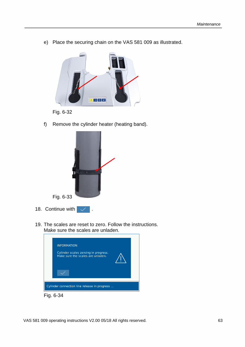
e) Place the securing chain on the VAS 581 009 as illustrated.
Fig. 6-32
f) Remove the cylinder heater (heating band).
Fig. 6-33
18. Continue with .
19. The scales are reset to zero. Follow the instructions. Make sure the scales are unladen.
Fig. 6-34
Maintenance
VAS 581 009 operating instructions V2.00 05/18 All rights reserved. 64
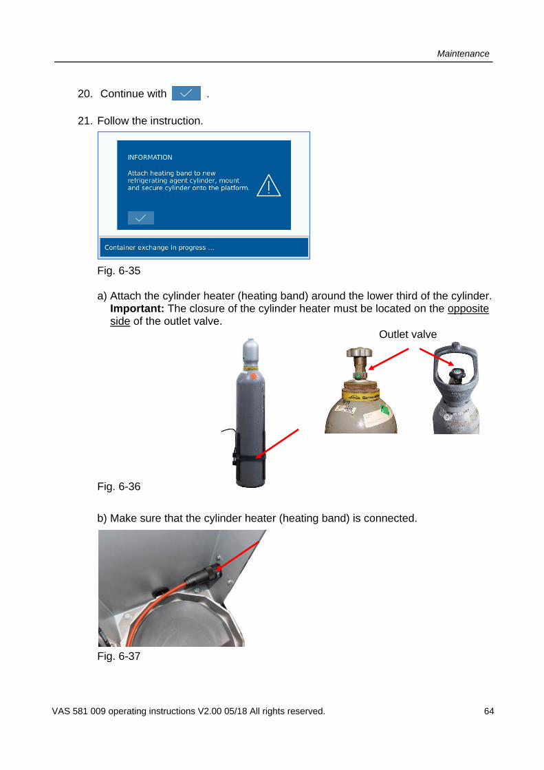
20. Continue with .
21. Follow the instruction.
Fig. 6-35
a) Attach the cylinder heater (heating band) around the lower third of the cylinder. Important: The closure of the cylinder heater must be located on the opposite side of the outlet valve.
Fig. 6-36
b) Make sure that the cylinder heater (heating band) is connected.
Fig. 6-37
Outlet valve

Maintenance
VAS 581 009 operating instructions V2.00 05/18 All rights reserved. 65
c) Place the new refrigerating agent cylinder onto the refrigerating agent scales. Note that the bottle heating cable is not placed on the balance during the assembly of the bottle. Attach the securing chain.
Fig. 6-38
22. Continue with .
23. Refrigerating agent cylinder with protective cap: Remove the protective cap. Make sure that the connection of the refrigerating agent cylinder is facing the device and not away.
Fig. 6-39

Maintenance
VAS 581 009 operating instructions V2.00 05/18 All rights reserved. 66
24. Zeroing and hose emptying are performed automatically.
Fig. 6-40
25. Remove the hose from the plastic cap if necessary.
Fig. 6-41
26. Remove the plastic cap on the outlet valve if necessary.
Fig. 6-42

Maintenance
VAS 581 009 operating instructions V2.00 05/18 All rights reserved. 67
27. Attach the supplied cylinder adapter. Torque: 30 … 32 Nm, max. 35 Nm.
Fig. 6-43
28. Connect the hose to the cylinder adapter. Spanner width: 14 mm. Torque: 16 … 18 Nm, max. 20 Nm.
Fig. 6-44
29. Continue with .

Maintenance
VAS 581 009 operating instructions V2.00 05/18 All rights reserved. 68
1. Make sure that the hose/hose connection is facing the device. It must not lead away from the rear of the device. This could lead to a faulty measurement of the cylinder weight.
Fig. 6-45
2. Follow the instructions and open the manual valve of the refrigerating agent cylinder.
Fig. 6-46
Fig. 6-47

Maintenance
VAS 581 009 operating instructions V2.00 05/18 All rights reserved. 69
3. End the replacement of the refrigerating agent cylinder with . The system is flushed with CO2, i.e. the filling hoses are first flooded with CO2, then the CO2 is discharged. The VAS 581 009 must not be connected to the vehicle at this time!
4. Exit the menu with .
5. Select to return to the main menu.
Maintenance
VAS 581 009 operating instructions V2.00 05/18 All rights reserved. 70
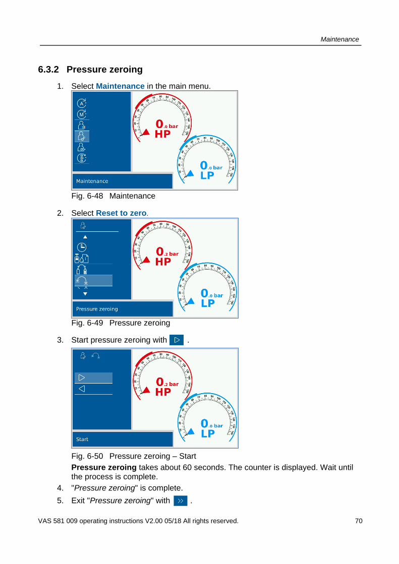
6.3.2 Pressure zeroing
1. Select Maintenance in the main menu.
Fig. 6-48 Maintenance
2. Select Reset to zero.
Fig. 6-49 Pressure zeroing
3. Start pressure zeroing with .
Fig. 6-50 Pressure zeroing – Start
Pressure zeroing takes about 60 seconds. The counter is displayed. Wait until the process is complete.
4. "Pressure zeroing" is complete.
5. Exit "Pressure zeroing" with .

Maintenance
VAS 581 009 operating instructions V2.00 05/18 All rights reserved. 71
6.3.3 Oil/UV additive scales zeroing
1. Select Maintenance in the main menu.
Fig. 6-51 Maintenance
2. Select Reset Oil/UV additive scales to zero.
Fig. 6-52 Oil/UV additive scales zeroing

Maintenance
VAS 581 009 operating instructions V2.00 05/18 All rights reserved. 72
3. Start Oil/UV additive scales zeroing .
Fig. 6-53 Scales zeroing
Follow the instructions on the display. (e.g. mount empty oil/UV additive containers, etc.). Note: The mounted oil containers must be completely empty for zeroing. If this is not the case, an error message may occur during zeroing.
4. "Oil/UV additive scales zeroing" is complete.
5. Exit "Oil/UV additive scales zeroing" with .
6.3.4 Oil regeneration
Select Maintenance│Oil regeneration│Carry out oil regeneration in main menu.
Oil regeneration is carried out automatically.
6.3.5 Save logs
Data is logged and can be copied to a USB stick in case of an error and sent to AVL DiTEST Service for error analysis. Logging is started/suspended with .
Note: Once data logging is enabled it remains active even when the device is switched off.

Maintenance
VAS 581 009 operating instructions V2.00 05/18 All rights reserved. 73
6.4 Add new printer paper
Press the black tab outwards and folder the cover up.
Fig. 6-54
Take the empty paper roll out and place a new one inside. Pay attention to the direction of rotation.
Fig. 6-55
Pull the paper out until it is visible from outside.
Close the cover.
Fig. 6-56
Press the black tab inwards. The printer is now ready for use.
Fig. 6-57

Maintenance
VAS 581 009 operating instructions V2.00 05/18 All rights reserved. 74
6.5 Replacing fuses
NOTICE
Only use original AVL DITEST fuses with the ID number EV0051 or fuses with the same specification: Glass tube fuse 5x20 mm, 6.3 A, 250 V, inert.
Pull the fuse unit out and replace with a new fuse.
Fig. 6-58

Maintenance
VAS 581 009 operating instructions V2.00 05/18 All rights reserved. 75
6.6 Other maintenance information
In case of problems, various maintenance steps can be carried out via the maintenance menu.
Select the desired function. Follow the instructions on the screen.
6.6.1 System information
The "System info" menu shows the software version
device type
serial number
HW revision status
6.6.2 Operating hours
Shows the total operating hours of the device, the total vacuum pump running time and number of switching cycles of the individual solenoid valves of the valve block.

Maintenance
VAS 581 009 operating instructions V2.00 05/18 All rights reserved. 76
6.6.3 Replacing quick connector seals
Tools required
2 slot screwdrivers (2 mm wide) Tweezers
Important: The screwdrivers and tweezers must have been carefully deburred and rounded.
Overview
The seal consists of two parts:
1 x O-ring
1 x supporting ring
Fig. 6-59
Supporting ring O-ring
Maintenance
VAS 581 009 operating instructions V2.00 05/18 All rights reserved. 77
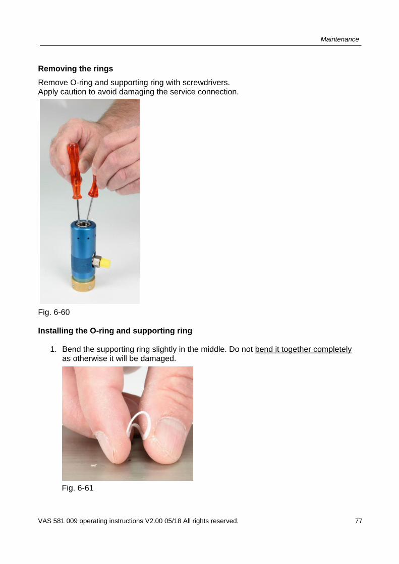
Removing the rings
Remove O-ring and supporting ring with screwdrivers. Apply caution to avoid damaging the service connection.
Fig. 6-60 Installing the O-ring and supporting ring
1. Bend the supporting ring slightly in the middle. Do not bend it together completely as otherwise it will be damaged.
Fig. 6-61
Maintenance
VAS 581 009 operating instructions V2.00 05/18 All rights reserved. 78
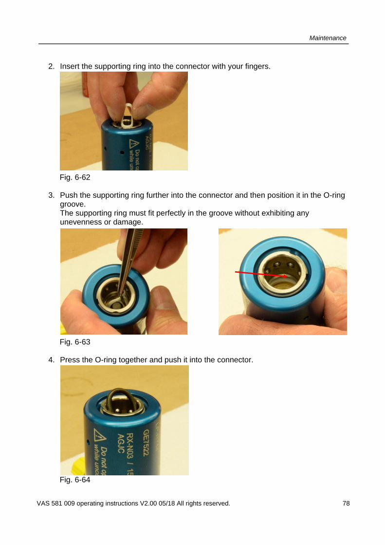
2. Insert the supporting ring into the connector with your fingers.
Fig. 6-62
3. Push the supporting ring further into the connector and then position it in the O-ring groove. The supporting ring must fit perfectly in the groove without exhibiting any unevenness or damage.
Fig. 6-63
4. Press the O-ring together and push it into the connector.
Fig. 6-64

Maintenance
VAS 581 009 operating instructions V2.00 05/18 All rights reserved. 79
5. Position the O-ring as shown in the following figures. The correct position is behind the supporting ring. The correct position is essential to the proper functioning of the connector and must be adhered to.
Fig. 6-65

Maintenance
VAS 581 009 operating instructions V2.00 05/18 All rights reserved. 80
6. Press one side of the O-ring under the supporting ring and into the O-ring groove. O-ring Supporting ring O-ring
Fig. 6-66
7. Push the O-ring further into the groove until the O-ring is seated evenly in the groove as shown in the figures.
Supporting ring O-ring Seated evenly all round
Fig. 6-67 If you experience problems or have any questions, please contact your AVL DiTEST service partner.
Service
VAS 581 009 operating instructions V2.00 05/18 All rights reserved. 81
7 Service
The "Service" operating mode is password-protected and may only be used by AVL DiTEST Service staff!

Overview
VAS 581 009 operating instructions V2.00 05/18 All rights reserved. 82
8 Overview
This overview shows all current system values.
Fig. 8-1 Explanation of the symbols
Pressure at high-pressure side
Pressure at low-pressure side
Pressure at refrigerating agent connection
CO2 concentration in %
Measured cylinder content
Calculated, usable cylinder content
Measured, available quantity of clean oil
Measured, available UV additive quantity
Measured oil quantity in used-oil container
Placing out of / into service / storage
VAS 581 009 operating instructions V2.00 05/18 All rights reserved. 83
9 Placing out of / into service / storage
9.1 Taking out of service
Observe the national regulations when emptying the CO2 (R744) refrigerating agent. Contact your service partner if in doubt.
9.1 Transport
Information
When transporting the air conditioning system, all safety instructions specified in applicable national accident prevention regulations must be complied with!
WARNING
Transport only without CO2 cylinder, empty or removed oil container, depressurised VAS 581 009 and in upright position!
9.2 Storage
To store the VAS 581 009, disconnect it from the power supply and place it in a safe location where it is not exposed to high temperatures, humidity and where there is no risk of impacts with other objects that may damage it. Please also take into account the technical data. The device should also be covered with the supplied cover. If stored for a prolonged period of time, we recommend that you remove the refrigerating agent cylinder and store it separately.
WARNING
Remove CO2 cylinder and heating band if stored in an environment where the temperature exceeds 50 °C!
9.3 Placing back into service
Check the VAS 581 009 in accordance with national laws and regulations before placing it back into service.

Troubleshooting / In case of error
VAS 581 009 operating instructions V2.00 05/18 All rights reserved. 84
10 Error table / in case of error
Try to determine the cause of the error and pinpoint its location as accurately as possible.
Follow the recommended steps on the screen and carry out all suggested measures.
If this does not resolve the error, please contact the responsible AVL DiTEST branch / AVL DiTEST partner in your country.
Warnings:
Warnings Possible cause/s, solution/s
Warning A warning indicates a problem during operation. However, the operation continues. LED indicator: flashes yellow
Insufficient refrigerating agent pressure.
Refrigerating agent cylinder not connected or empty Self-test continues.
Not enough paper in the printer; replace paper roll.
There is not enough paper in the printer for printing. Please replace the paper roll.
Device moving; please stabilise device.
The cylinder weight is monitored prior to filling. If a discrepancy is detected (e.g. if the cylinder moves), the filling process does not start. Stabilise the device so that the filling process can start.
Insufficient refrigerating agent; refrigerating agent cylinder must be replaced. Proceed anyway?
Before a process that depends on the refrigerating agent starts, a check is performed to ensure that a sufficient quantity is available. If no sufficient quantity is available, this message appears. The refrigerating agent cylinder needs to be replaced. Do you want to try to perform the step anyway?
Refrigerating agent cylinder not connected or nearly empty.
Refrigerating agent cylinder not connected or empty Connect a refrigerating agent cylinder containing a sufficient quantity of refrigerating agent.
Oil filling incomplete Proceed anyway?
The desired oil quantity could not be injected within the specified time. Do you want to continue with the injection process anyway?
UV additive injection incomplete Proceed anyway?
The desired quantity of UV additive could not be injected within the specified time. Do you want to continue with the injection process anyway?

Troubleshooting / In case of error
VAS 581 009 operating instructions V2.00 05/18 All rights reserved. 85
Error messages:
Error message Possible cause/s, solution/s
Error An error indicates that the current operation needs to be aborted due to a problem. LED indicator: flashing red
Wrong pressure at CO2 outlet. Maintenance/repair required.
The measured pressure at the CO2 outlet is incorrect. Maintenance/repair by service technician required.
Leak detected. Target pressure of evacuation could not be reached within the specified time. Check device for leak.
Draining failed. Draining the refrigerating agent has failed. Remaining pressure could not be released within the specified time. Repeat the process.
Air conditioning circuit still under pressure; termination.
The vehicle cannot be filled with refrigerating agent, because it is already or still filled. If you wish to continue with filling, first drain the refrigerating agent.
Too high pressure while generating vacuum; termination.
Overpressure with potential of damaging vacuum pump was detected while generating vacuum. The process was therefore aborted. Drain any refrigerating agent from the system and repeat the step.
Filling incomplete. Replace refrigerating agent cylinder.
Filling could not be completed due to insufficient quantity of refrigerating agent. The refrigerating agent cylinder must be replaced.
Pressure test failed. Replace refrigerating agent cylinder.
The pressure test cannot be performed due to insufficient quantity of refrigerating agent. The refrigerating agent cylinder must be replaced.
Pressure test failed. Leak in air conditioning system.
Excessive pressure drop in system during pressure test. The most common cause is a leak in the air conditioning system of the vehicle.
Draining of hose failed. Draining of hose taking too long; operation was aborted. Vehicle may still be connected or valve to vehicle leaking.
Device moving; termination. The cylinder weight is monitored during filling. If a discrepancy is detected (e.g. if the cylinder moves), the filling process is aborted. Repeat the filling process and don't move the device during this process.
Manual valve on refrigerating agent cylinder still open; termination.
Following the request to close the manual valve on the cylinder, the system pressure cannot be released. This typically occurs when the manual valve has not be closed correctly. Check.
Internal pressure test failed. Maintenance/repair required.
Error detected during internal pressure test. Maintenance/repair by service technician required.
Troubleshooting / In case of error
VAS 581 009 operating instructions V2.00 05/18 All rights reserved. 86
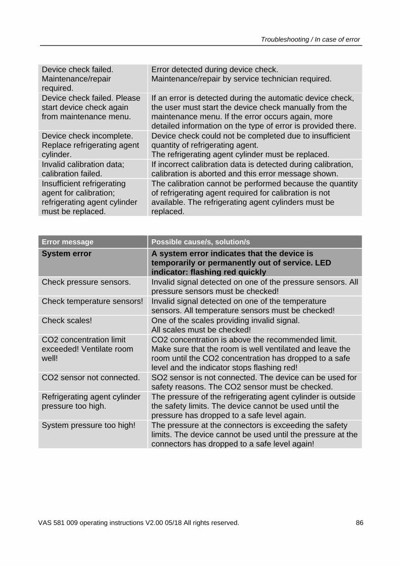
Device check failed. Maintenance/repair required.
Error detected during device check. Maintenance/repair by service technician required.
Device check failed. Please start device check again from maintenance menu.
If an error is detected during the automatic device check, the user must start the device check manually from the maintenance menu. If the error occurs again, more detailed information on the type of error is provided there.
Device check incomplete. Replace refrigerating agent cylinder.
Device check could not be completed due to insufficient quantity of refrigerating agent. The refrigerating agent cylinder must be replaced.
Invalid calibration data; calibration failed.
If incorrect calibration data is detected during calibration, calibration is aborted and this error message shown.
Insufficient refrigerating agent for calibration; refrigerating agent cylinder must be replaced.
The calibration cannot be performed because the quantity of refrigerating agent required for calibration is not available. The refrigerating agent cylinders must be replaced.
Error message Possible cause/s, solution/s
System error A system error indicates that the device is temporarily or permanently out of service. LED indicator: flashing red quickly
Check pressure sensors. Invalid signal detected on one of the pressure sensors. All pressure sensors must be checked!
Check temperature sensors! Invalid signal detected on one of the temperature sensors. All temperature sensors must be checked!
Check scales! One of the scales providing invalid signal. All scales must be checked!
CO2 concentration limit exceeded! Ventilate room well!
CO2 concentration is above the recommended limit. Make sure that the room is well ventilated and leave the room until the CO2 concentration has dropped to a safe level and the indicator stops flashing red!
CO2 sensor not connected. SO2 sensor is not connected. The device can be used for safety reasons. The CO2 sensor must be checked.
Refrigerating agent cylinder pressure too high.
The pressure of the refrigerating agent cylinder is outside the safety limits. The device cannot be used until the pressure has dropped to a safe level again.
System pressure too high! The pressure at the connectors is exceeding the safety limits. The device cannot be used until the pressure at the connectors has dropped to a safe level again!

Troubleshooting / In case of error
VAS 581 009 operating instructions V2.00 05/18 All rights reserved. 87
Error/error messages, electrical:
Error/error message Possible cause/s Solution/s
Device does not switch on No power Check power supply. Check fuses.
Error/error messages, mechanical:
Error/error message Possible cause/s Solution/s
Self-test does not start No refrigerating agent Connect or open refrigerating agent cylinder
Disconnect from vehicle
Close gas cylinder and discharge manually
Not enough oil Oil container empty Fill oil container
Check connection Vehicle not connected or empty
Connect quick connectors to vehicle
Oil level: oil level too low Oil container empty Fill oil container
Circuit under pressure Drain

Maintenance and care
VAS 581 009 operating instructions V2.00 05/18 All rights reserved. 88
11 Maintenance and care
11.1 Visual inspection
Periodically perform a visual inspection.
Check all parts for damage (e.g. fractures) and dirt.
Check the service adapters regularly for damage.
CAUTION
Always replace damaged parts (power cable, quick connectors, connecting hoses, cylinder adapters)!
11.2 Cleaning
Wipe the VAS 581 009 with a lint-free cloth. You can moisten the cloth with water or non-alkaline detergent. Make sure that the cloth is damp but not wet.
CAUTION
Pull the plug before cleaning! The device must not be pressurised! Make sure that no liquid penetrates into the housing.

Technical data
VAS 581 009 operating instructions V2.00 05/18 All rights reserved. 89
12 Technical data:
General data
Refrigerating agent R744
Nominal voltage 230 VAC
Frequency 50 Hz
Power consumption 1.2 kW
Weight approx, 75 kg
Dimensions 67x100x81 cm
Display 7-inch graphic TFT colour display
Controls Multi-functional dial
Pressure indicator Digital (HP and LP)
PC interface USB interface
Max. pressure HP 140 bar; LP 130 bar
Hose length 2.5 m
Printer Thermal printer, 24 bars
Interface USB standard
Refrigerating agent
Refrigerating agent R744
Cylinder weight 5, 6, 10 or 20 kg
Cylinder type Cylinder with integrated riser
Load cell max. 50 kg
Scales accuracy ± 10 g
Oil/UV additive
Oil container 3 (1 clean oil container; 1 used oil container, 1 additive container)
Oil container volume 250 ml
Load cell 3 kg
Oil/UV additive accuracy ± 2 g / ± 2 g
Vacuum pump
Suction capacity 3 m³/h
End pressure 0.002 mbar
Service interval 500 h / 1 year
Climatic conditions
Operating temperature +10 ... +50 °C
Storage and transport temperature -25 ...+80 °C
Humidity 10 ... 90 % non-condensing
Disposal: For disposal, it is essential to comply with local legal obligations!

Error reporting fax
VAS 581 009 operating instructions V2.00 05/18 All rights reserved. 90
13 Error reporting fax
Fax no.:
Please fill in all applicable sections (ideally in English or German) and fax to responsible service centre.
1. Registration details
Serial number Is you device still covered by the warranty (12 months)? Yes
If yes, please include proof of warranty (registration and copy of delivery note).
2. Dealer information
Authorised VW workshop Independent workshop
Sales centre / importer No. Dealership no.
Company name Tax ID No.1
Contact Telephone Fax
Postal address: Delivery address (if different from postal address):
Street No. Street No.
Postcode Place Postcode Place
Country Country
Tel. No. Tel.-No.
Fax No. Fax No.
1. for EU countries only

Error reporting fax
VAS 581 009 operating instructions V2.00 05/18 All rights reserved. 91
Error reporting fax continuation
3. Problem description
Basic problems
Error message/pattern:
Is the error reproducible? Yes ❏
Does the error occur sporadically? Yes ❏
What software version is installed?
Software:
We hereby acknowledge that we are aware and accept the service conditions for replacing
components.
Place Date Signature Stamp

Index
VAS 581 009 operating instructions V2.00 05/18 All rights reserved. 92
14 Index
A
Acceptance report 16 Add new printer paper 72 Ad-hoc maintenance, as required 53 Automatic mode 30 Available accessories 29
B
Balance sheet 43
C
Change vacuum pump oil 47 Check oil level (vacuum pump oil) 50 Cleaning 87 Controls 23 Customer data 35 Cylinder adapter 51
D
Date and time 42 Design 17 Drain hose 35 Draining 36
E
EC Declaration of Conformity / CE marking 15 Error reporting fax 89 Error table / in case of error 83
F
Filling 38 Firmware update 43 Front view 17
G
General information 14 Generating vacuum 37
I
Intended use 16
L
Language 43 LP and HP quick connectors 52
M
Maintenance 45 Maintenance and care 87 Maintenance schedule 45 Manual mode 33
O
Oil regeneration 71 Oil/UV additive scales zeroing 70 Operating hours 74 Other applicable documents 16 Other maintenance information 74 Overview of operating modes 27
P
Placing back into service 82 Placing out of / into service / storage 82 Pressure test 39 Pressure zeroing 69 Printout text size 44
Q
Quick connectors 20
R
Rear view 19 Refrigerating agent cylinder CO2 (R744) 21, 50, 53 Regular maintenance 47 Replacing fuses 73
Index
VAS 581 009 operating instructions V2.00 05/18 All rights reserved. 93
S
Safety instructions 15 SAFETY INSTRUCTIONS 4 Save logs 71 Scope of application 16 Scope of delivery 28 Service 80 Settings 42 Side view, right 18 Software licence 16 Storage 82 System delivery 28 System information 74
T
Taking out of service 82 Technical data: 88 Text and number inputs 26 Transport 82
U
Units 42 User interface operation 24 User prompts 25
V
Visual inspection 87
W
Workshop data 43
We have checked the contents of the documentation for compliance with the described condition. However, deviations cannot be ruled out completely and we offer no guarantee full compliance. The information provided in this documentation is checked regularly and necessary corrections are incorporated in subsequent editions. We are always thankful for suggestions for improvement.
We reserve the right to make changes to the form, equipment and technology of the delivery. No rights can be derived from the specifications, figures and descriptions in these operating instructions. Without the written permission of the Volkswagen Group / the manufacture, reprinting, reproduction and translation, in part or in whole, is only permitted to the extent that every device is provided with its own documentation. Transfer to third parties is not permitted. The Volkswagen Group / the manufacturer expressly reserves all rights under the German Copyright Act. Subject change.
VOLKSWAGEN AG KD-WERKSTATTAUSRÜSTUNG D-38436 Wolfsburg Copyright Volkswagen AG 2018, AVL DiTEST 2018
Manufacturer: AVL DiTEST GmbH Alte Poststraße 156 A-8020 Graz All rights reserved.