user manual - mediacdn.eu · general safety summary carefully read the following safety precautions...
TRANSCRIPT

User Manual
SDG1000X Series Function/Arbitrary Waveform Generator
UM0201X-E01A
2016 SIGLENT TECHNOLOGIES CO., LTD


SIGLENT
SDG1000X User Manual I
Declaration
Copyright © SIGLENT TECHNOLOGIES CO., LTD. All rights reserved.
Without permission, contents in this manual are not allowed to be copied,
extracted or translated.

SIGLENT
II SDG1000X User Manual
General Safety Summary
Carefully read the following safety precautions to avoid any personal injuries
or damages to the instrument and any product connected to it. To avoid
potential hazards, please use the instrument as specified.
Only qualified technical personnel should service this instrument.
Avoid fire or open flame.
Use properly rated power line connections.
Use only the specified power line which has been approved by your local
regulatory agency.
Ground the Instrument.
The instrument is grounded through the protective ground conductor of the
power line. To avoid electric shock, the ground conductor must be connected
to the earth ground. Make sure the instrument is grounded correctly before
connecting its input or output terminals.
Connect the signal wire correctly.
The potential of the signal wire ground is equal to the earth, therefore do not
connect the signal wire to a high voltage. Do not touch the exposed contacts
or components.
Observe all terminal ratings.
To avoid fire or electric shock, please observe all ratings and sign instructions
on the instrument. Before connecting the instrument, please read the manual
carefully to gain more information about the ratings.
Do not operate with suspected failures.
If you suspect that the product is damaged, please let only qualified service
personnel check it.
Avoid circuit or wire exposure.
Do not touch exposed contacts or components when the power is on.
Do not operate in wet/damp conditions.
Do not operate in an explosive atmosphere.
Keep the surface of the instrument clean and dry.
SIGLENT
SDG1000X User Manual III
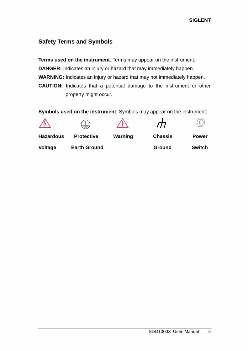
Safety Terms and Symbols
Terms used on the instrument. Terms may appear on the instrument:
DANGER: Indicates an injury or hazard that may immediately happen.
WARNING: Indicates an injury or hazard that may not immediately happen.
CAUTION: Indicates that a potential damage to the instrument or other
property might occur.
Symbols used on the instrument. Symbols may appear on the instrument:
Hazardous Protective Warning Chassis Power
Voltage Earth Ground Ground Switch
SIGLENT
IV SDG1000X User Manual
Introduction to SDG1000X
The manual covers the following 2 models of SDG1000X Series
Function/Arbitrary Waveform Generators: SDG1032X and SDG1062X.
SIGLENT‘s SDG1000X is a series of dual-channel function/arbitrary waveform
generators with specifications of up to 60MHz maximum bandwidth, 150MSa/s
sampling rate and 14-bit vertical resolution. The proprietary EasyPulse
technology helps to solve the weaknesses inherent in traditional DDS
generators when generating pulse waveforms, and the special square wave
generator is capable of generating square waveforms with up to 60MHz
frequency and low jitter. With these advantages, the SDG1000X can provide
users with a variety of high fidelity and low jitter signals and can meet the
growing requirements of complex and extensive applications.
Key Features
Dual-channel,with bandwidth up to 60MHz and amplitude up to 20Vpp
150MSa/s sampling rate, 14-bit vertical resolution, and 16kpts waveform
length
Innovative Easy Pulse technology, capable of generating lower jitter Pulse
waveforms, brings a wide range and extremely high precision in pulse
width and rise/fall times adjustment
Special circuit for Square waves, which can generate Square wave with
frequencies up to 60MHz and jitter less than 300ps+0.05ppm of period
A variety of analog and digital modulation types: AM、DSB-AM、FM、PM、
FSK、ASK 、PSK and PWM
Sweep and Burst functions
Harmonic waveforms generating function
Waveforms combining function
SIGLENT
SDG1000X User Manual V
High precision Frequency Counter
196 kinds of built-in arbitrary waveforms
Standard interfaces: USB Host, USB Device(USBTMC), LAN(VXI-11)
Optional interface: GPIB
4.3‖ display
SIGLENT
VI SDG1000X User Manual
Catalog
General Safety Summary ................................................................................ II
Introduction to SDG1000X ............................................................................ IV
1 Quick Start ................................................................................................ 1
1.1 Handle Adjustment ....................................................................... 2
1.2 The Front/Rear Panel ................................................................... 3
1.3 To Select a Waveform ................................................................... 8
1.4 To Set Modulation/Sweep/Burst.................................................. 12
1.5 To Turn On/Off Output ................................................................ 14
1.6 To Use Numeric Input ................................................................. 15
1.7 To Use Common Function Keys ................................................. 16
2 Front Panel Operations ........................................................................... 17
2.1 To Set Sine Waveform ................................................................ 18
2.2 To Set Square Waveform ............................................................ 23
2.3 To Set Ramp Waveform .............................................................. 26
2.4 To Set Pulse Waveform .............................................................. 28
2.5 To Set Noise Waveform .............................................................. 32
2.6 To Set DC Waveform .................................................................. 35
2.7 To Set Arbitrary Waveform .......................................................... 36
2.8 To Set Harmonic Function .......................................................... 45
2.9 To Set Modulation Function ........................................................ 48
2.9.1 AM ........................................................................................ 49
2.9.2 DSB-AM ............................................................................... 52
2.9.3 FM ........................................................................................ 54
2.9.4 PM ........................................................................................ 56
2.9.5 FSK ...................................................................................... 58
2.9.6 ASK ...................................................................................... 60
2.9.7 PSK ...................................................................................... 61
2.9.8 PWM .................................................................................... 63
2.10 To Set Sweep Function ............................................................... 66
2.11 To Set Burst Function ................................................................. 71
2.12 To Store and Recall .................................................................... 77
2.12.1 Storage System ............................................................. 78

SIGLENT
SDG1000X User Manual VII
2.12.2 File Type ........................................................................ 79
2.12.3 File Operation ................................................................ 81
2.13 To Set Utility Function ................................................................. 85
2.13.1 System Settings ............................................................. 87
2.13.2 Test/Cal .......................................................................... 95
2.13.3 Frequency Counter ........................................................ 99
2.13.4 Output .......................................................................... 102
2.13.5 CH Copy/Coupling ....................................................... 105
2.13.6 Remote Interface ......................................................... 110
2.13.7 Sync Output ................................................................. 116
2.13.8 Clock Source ................................................................ 118
2.13.9 Mode ............................................................................ 119
2.13.10 Overvoltage Protection................................................. 121
3 Examples .............................................................................................. 122
3.1 Example 1: Generate a Sine Waveform ................................... 123
3.2 Example 2: Generate a Square Waveform ............................... 125
3.3 Example 3: Generate a Ramp Waveform ................................. 127
3.4 Example 4: Generate a Pulse Waveform .................................. 129
3.5 Example 5: Generate a Noise .................................................. 131
3.6 Example 6: Generate a DC Waveform ..................................... 132
3.7 Example 7: Generate a Linear Sweep Waveform ..................... 133
3.8 Example 8: Generate a Burst Waveform .................................. 135
3.9 Example 9: Generate an AM Modulation Waveform ................. 137
3.10 Example 10: Generate a FM Modulation Waveform ................. 139
3.11 Example 11: Generate a PM Modulation Waveform ................. 141
3.12 Example 12: Generate a FSK Modulation Waveform ............... 143
3.13 Example 13: Generate an ASK Modulation Waveform ............. 145
3.14 Example 14: Generate a PSK Modulation Waveform ............... 147
3.15 Example 15: Generate a PWM Modulation Waveform ............. 149
3.16 Example 16: Generate a DSB-AM Modulation Waveform ........ 151
4 Troubleshooting .................................................................................... 153
4.1 General Inspecting ................................................................... 153
4.2 Troubleshooting ........................................................................ 154
5 Service and Support ............................................................................. 155

SIGLENT
VIII SDG1000X User Manual
5.1 Maintenance summary ............................................................. 155
5.2 Contact SIGLENT ..................................................................... 156
6 Appendix ............................................................................................... 157
Appendix A: Accessories ...................................................................... 157
Appendix B: Daily Maintain and Cleaning ............................................ 158

SIGLENT
SDG1000X User Manual 1
1 Quick Start
This chapter covers the following topics:
Handle Adjustment
The Front/Rear Panel
To Select a Waveform
To Set Modulation/Sweep/Burst
To Turn On/Off Output
To Use Numeric Input
To Use Common Function Keys
SIGLENT
2 SDG1000X User Manual
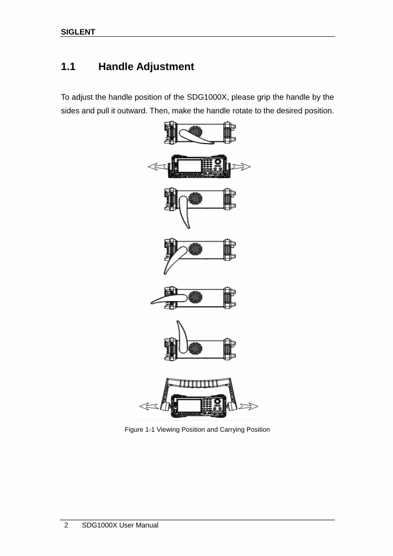
1.1 Handle Adjustment
To adjust the handle position of the SDG1000X, please grip the handle by the
sides and pull it outward. Then, make the handle rotate to the desired position.
Figure 1-1 Viewing Position and Carrying Position

SIGLENT
SDG1000X User Manual 3
1.2 The Front/Rear Panel
This chapter will provide a brief introduction and description for the operation
and functions of the front/rear panel.
Front Panel
SDG1000X has a clear and simple front panel which includes a 4.3 inch
screen, menu softkeys, numeric keyboard, knob, function keys, arrow keys,
and channel control area.
Figure 1-2 Front Panel of SDG1000X
USB
Host
Numeric Keyboard Knob
Power Key
User Interface
Menu
Softkeys
Function
Keys Channel
Control
Arrow
Keys
SIGLENT
4 SDG1000X User Manual
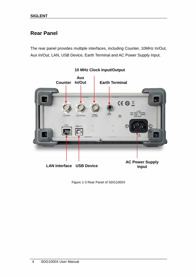
Rear Panel
The rear panel provides multiple interfaces, including Counter, 10MHz In/Out,
Aux In/Out, LAN, USB Device, Earth Terminal and AC Power Supply Input.
Figure 1-3 Rear Panel of SDG1000X
Aux
In/Out
10 MHz Clock Input/Output
Earth Terminal
LAN Interface USB Device AC Power Supply
Input
Counter

SIGLENT
SDG1000X User Manual 5
User Interface
The SDG1000X can only display parameters and waveform information for
one channel at a time. The picture below shows the interface when CH1
chooses AM modulation of a sine waveform. The information displayed may
vary depending on the function selected.
Figure 1-4 User Interface
1. Waveform Display Area
Displays the currently selected waveform of each channel.
2. Channel Status Bar
Indicates the selected status and output configuration of the channels.
3. Basic Waveform Parameters Area
Shows the current waveform‘s parameters of each channel. Press Parameter
and select the corresponding softkey to highlight the parameter to configure.
Then use number keys or knob to change the parameter value.
4
3
8 7 6 5
1 2
SIGLENT
6 SDG1000X User Manual
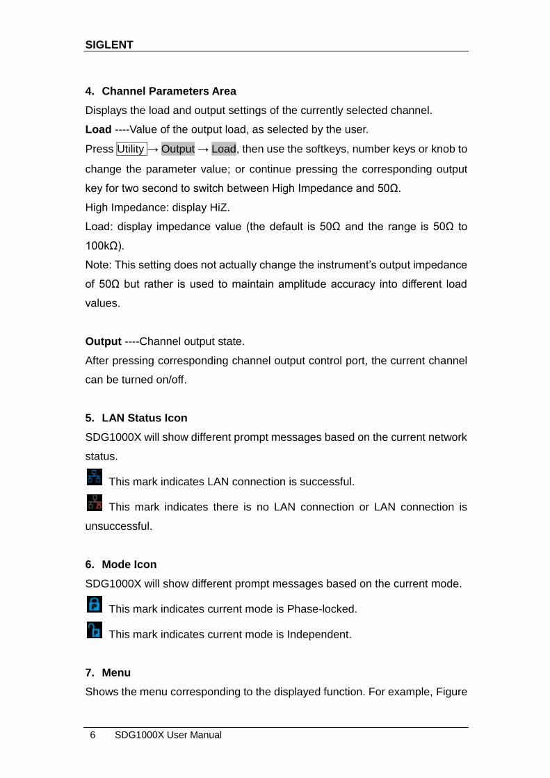
4. Channel Parameters Area
Displays the load and output settings of the currently selected channel.
Load ----Value of the output load, as selected by the user.
Press Utility → Output → Load, then use the softkeys, number keys or knob to
change the parameter value; or continue pressing the corresponding output
key for two second to switch between High Impedance and 50Ω.
High Impedance: display HiZ.
Load: display impedance value (the default is 50Ω and the range is 50Ω to
100kΩ).
Note: This setting does not actually change the instrument‘s output impedance
of 50Ω but rather is used to maintain amplitude accuracy into different load
values.
Output ----Channel output state.
After pressing corresponding channel output control port, the current channel
can be turned on/off.
5. LAN Status Icon
SDG1000X will show different prompt messages based on the current network
status.
This mark indicates LAN connection is successful.
This mark indicates there is no LAN connection or LAN connection is
unsuccessful.
6. Mode Icon
SDG1000X will show different prompt messages based on the current mode.
This mark indicates current mode is Phase-locked.
This mark indicates current mode is Independent.
7. Menu
Shows the menu corresponding to the displayed function. For example, Figure

SIGLENT
SDG1000X User Manual 7
1-4 shows the parameters of ―AM modulation‖.
8. Modulation Parameters Area
Shows the parameters of the current modulation function. After selecting the
corresponding menu, use number keys or knob to change the parameter
value.

SIGLENT
8 SDG1000X User Manual
1.3 To Select a Waveform
Press Waveforms to enter the menu as Figure 1-5 shows. The example below
will help familiarize with the waveform selection settings.
Figure 1-5 Waveform Selections
1. Press Waveforms key and then press Sine softkey. The SDG1000X can
generate sine waveforms with frequencies from 1μHz to 60MHz. By
setting Frequency/Period, Amplitude/High level, Offset/Low level and
Phase, a sine waveform with different parameters can be generated.
Figure 1-6 Sine Display Interface
2. Press Waveforms key and then press Square softkey. The generator can
generate square waveforms with frequencies from 1μHz to 60MHz and
variable duty cycle. By setting Frequency/Period, Amplitude/High level,
Offset/Low level, Phase and DutyCycle, a square waveform with different
parameters can be generated.

SIGLENT
SDG1000X User Manual 9
Figure 1-7 Square Display Interface
3. Press Waveforms key and then press Ramp softkey. The generator can
generate ramp waveforms with frequencies from 1μHz to 500kHz and
variable symmetry. By setting Frequency/Period, Amplitude/High level,
Offset/Low level, Phase and Symmetry, a ramp waveform with different
parameters can be generated.
Figure 1-8 Ramp Display Interface
4. Press Waveforms key and then press Pulse softkey. The generator can
generate pulse waveforms with frequencies from 1μHz to 12.5 MHz and
variable pulse width and rise/fall times. By setting Frequency/Period,
Amplitude/High level, Offset/Low level, PulWidth/Duty, Rise/Fall and Delay,

SIGLENT
10 SDG1000X User Manual
a pulse waveform with different parameters can be generated.
Figure 1-9 Pulse Display Interface
5. Press Waveforms key and then press Noise softkey. The generator can
generate noise with a 60MHz bandwidth. By setting Stdev and Mean,
noise with different parameters can be generated.
Figure 1-10 Noise Display Interface
6. Press Waveforms key and then press Page 1/2, last press the DC softkey.
The generator can generate a DC signal with a level up to ±10V into a
HighZ load or ±5V into a 50Ω load.
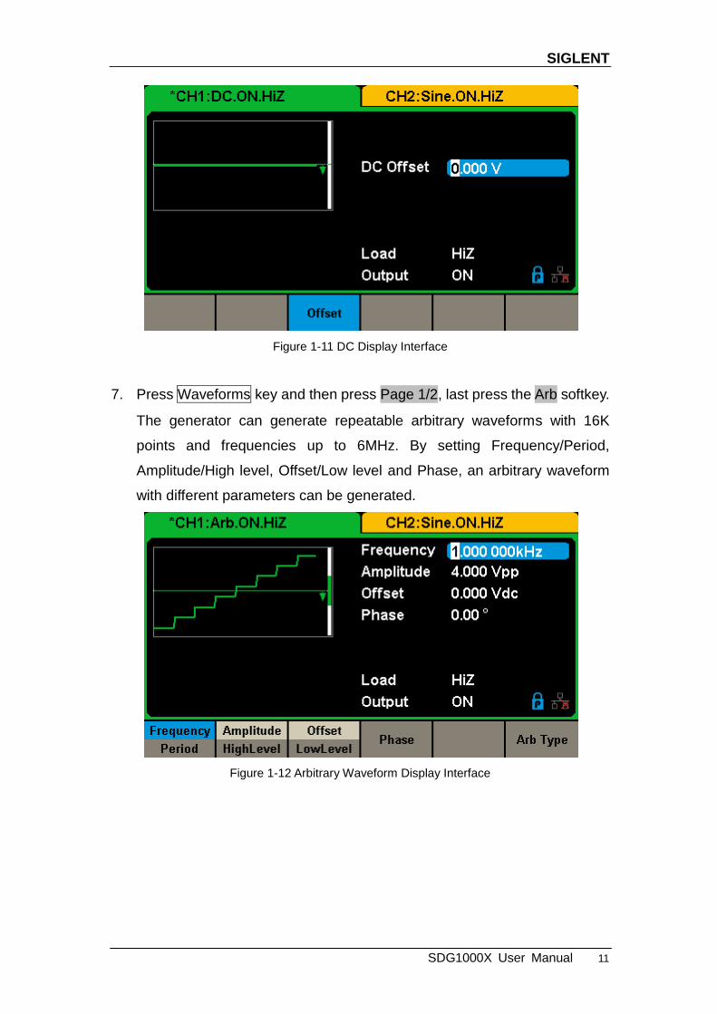
SIGLENT
SDG1000X User Manual 11
Figure 1-11 DC Display Interface
7. Press Waveforms key and then press Page 1/2, last press the Arb softkey.
The generator can generate repeatable arbitrary waveforms with 16K
points and frequencies up to 6MHz. By setting Frequency/Period,
Amplitude/High level, Offset/Low level and Phase, an arbitrary waveform
with different parameters can be generated.
Figure 1-12 Arbitrary Waveform Display Interface

SIGLENT
12 SDG1000X User Manual
1.4 To Set Modulation/Sweep/Burst
As shown in Figure 1-13, there are three keys on the front panel which are
used for modulation, sweep and burst settings. The instructions below will help
to explain these functions.
Figure 1-13 Modulate/Sweep/Burst Key
1. Press Mod, the Modulation function will be enabled.
The modulated waveform can be changed by modifying the parameters such
as Type, Source, AM Depth, AM Freq, Shape, etc. The SDG1000X can
modulate waveforms using AM, FM, PM, ASK, FSK, PSK, PWM and DSB-AM,
etc. Pulse waveforms can only be modulated using PWM. Noise and DC
waveforms cannot be modulated.
Figure 1-14 Modulation Display Interface
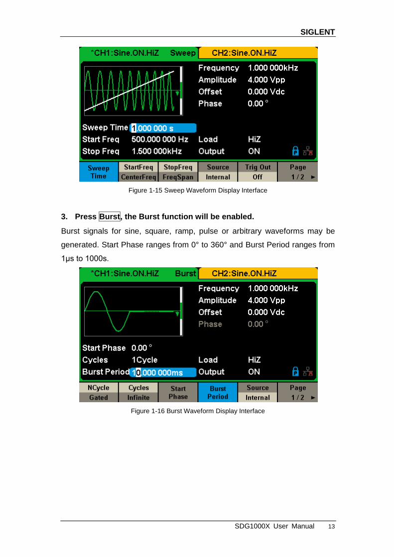
2. Press Sweep, the Sweep function will be enabled.
Sine, square, ramp and arbitrary waveforms support the sweep function. In
sweep mode, the SDG1000X can generate signals with variable frequency.
The available range of sweep time is from 1ms to 500s. The trigger source can
be ―Internal‖, ―External‖ or ―Manual‖.
SIGLENT
SDG1000X User Manual 13
Figure 1-15 Sweep Waveform Display Interface
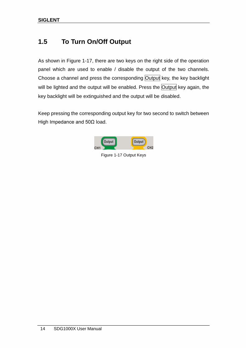
3. Press Burst, the Burst function will be enabled.
Burst signals for sine, square, ramp, pulse or arbitrary waveforms may be
generated. Start Phase ranges from 0° to 360° and Burst Period ranges from
1μs to 1000s.
Figure 1-16 Burst Waveform Display Interface
SIGLENT
14 SDG1000X User Manual
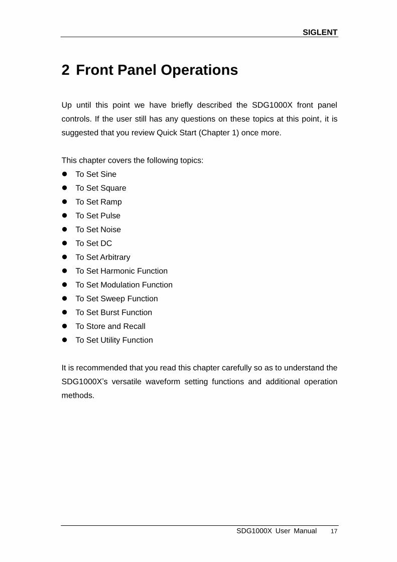
1.5 To Turn On/Off Output
As shown in Figure 1-17, there are two keys on the right side of the operation
panel which are used to enable / disable the output of the two channels.
Choose a channel and press the corresponding Output key, the key backlight
will be lighted and the output will be enabled. Press the Output key again, the
key backlight will be extinguished and the output will be disabled.
Keep pressing the corresponding output key for two second to switch between
High Impedance and 50Ω load.
Figure 1-17 Output Keys

SIGLENT
SDG1000X User Manual 15
1.6 To Use Numeric Input
As shown in
Figure 1-18, there are three sets of keys on the front panel, which are arrow
keys, knob and numeric keyboard. The instructions below will help to
familiarize you with the digital input selection.
Figure 1-18 Front Panel Digital Input
1. The numeric keyboard is used to enter the parameter‘s value.
2. The knob is used to increase (clockwise) or decrease (counterclockwise)
the current digit when setting parameters
3. When using knob to set parameters, the arrow keys are used to select the
digit to be modified; When using numeric keyboard to set parameters, the
left arrow key is used as a Backspace function.

SIGLENT
16 SDG1000X User Manual
1.7 To Use Common Function Keys
As shown in Figure 1-19, there are five keys on the operation panel which are
labeled Parameter, Utility, Store/Recall, Waveforms, and Ch1/Ch2. The
instructions below will help to familiarize you with these functions.
Figure 1-19 Waveforms Utility and Parameter Key
1. The Parameter key makes it convenient for the operator to set the
parameters of basic waveforms directly.
2. The Utility key is used to set the auxiliary system function, such as output
configurations, interface setting, system setting information, performing
the instrument self-test and reading the calibration information, etc.
3. The Store/Recall key is used to store and recall waveform data and
configuration information.
4. The Waveforms key is used to select basic waveforms.
5. The Ch1/Ch2 key is used to switch the currently selected channel
between CH1 and CH2. After start-up, CH1 is selected as default. At this
point, press the key to select CH2.
SIGLENT
SDG1000X User Manual 17
2 Front Panel Operations
Up until this point we have briefly described the SDG1000X front panel
controls. If the user still has any questions on these topics at this point, it is
suggested that you review Quick Start (Chapter 1) once more.
This chapter covers the following topics:
To Set Sine
To Set Square
To Set Ramp
To Set Pulse
To Set Noise
To Set DC
To Set Arbitrary
To Set Harmonic Function
To Set Modulation Function
To Set Sweep Function
To Set Burst Function
To Store and Recall
To Set Utility Function
It is recommended that you read this chapter carefully so as to understand the
SDG1000X‘s versatile waveform setting functions and additional operation
methods.
SIGLENT
18 SDG1000X User Manual
2.1 To Set Sine Waveform
Press Waveforms key to select the waveform function and then press the Sine
softkey. The sine waveform parameters are set by using the sine operation
menu.
The parameters available for sine waveforms include frequency/period,
amplitude/high level, offset/low level and phase. Different sine signals can be
generated by setting these parameters. As shown in Figure 2-1, in the soft key
menu, select Frequency. The frequency parameter area is highlighted in the
parameter display window, and users can set the frequency value here.
Figure 2-1 Sine Parameters Display Interface
Table2-1 Menu Explanations of Sine Waveform
Function menu
Settings Explanations
Frequency/ Period
Set the signal frequency or period; The current parameter will be switched at a second press.
Amplitude/ HighLevel
Set the signal amplitude or high level; The current parameter will be switched at a second press.
Offset/ LowLevel
Set the signal offset or low level; The current parameter will be switched at a second press.
Phase Set the phase of the signal.
SIGLENT
SDG1000X User Manual 19
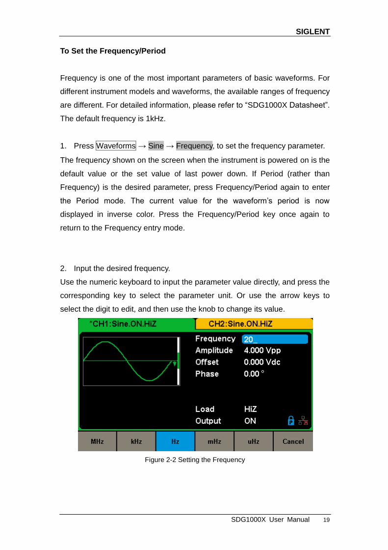
To Set the Frequency/Period
Frequency is one of the most important parameters of basic waveforms. For
different instrument models and waveforms, the available ranges of frequency
are different. For detailed information, please refer to ―SDG1000X Datasheet‖.
The default frequency is 1kHz.
1. Press Waveforms → Sine → Frequency, to set the frequency parameter.
The frequency shown on the screen when the instrument is powered on is the
default value or the set value of last power down. If Period (rather than
Frequency) is the desired parameter, press Frequency/Period again to enter
the Period mode. The current value for the waveform‘s period is now
displayed in inverse color. Press the Frequency/Period key once again to
return to the Frequency entry mode.
2. Input the desired frequency.
Use the numeric keyboard to input the parameter value directly, and press the
corresponding key to select the parameter unit. Or use the arrow keys to
select the digit to edit, and then use the knob to change its value.
Figure 2-2 Setting the Frequency
SIGLENT
20 SDG1000X User Manual
Note:
When using the numeric keyboard to enter the value, the left arrow key can be
used to move the cursor backward and delete the value of the previous digit.
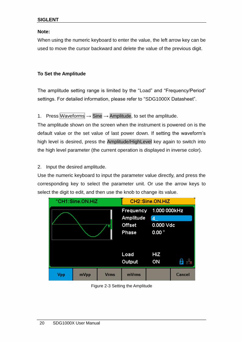
To Set the Amplitude
The amplitude setting range is limited by the ―Load‖ and ―Frequency/Period‖
settings. For detailed information, please refer to ―SDG1000X Datasheet‖.
1. Press Waveforms → Sine → Amplitude, to set the amplitude.
The amplitude shown on the screen when the instrument is powered on is the
default value or the set value of last power down. If setting the waveform‘s
high level is desired, press the Amplitude/HighLevel key again to switch into
the high level parameter (the current operation is displayed in inverse color).
2. Input the desired amplitude.
Use the numeric keyboard to input the parameter value directly, and press the
corresponding key to select the parameter unit. Or use the arrow keys to
select the digit to edit, and then use the knob to change its value.
Figure 2-3 Setting the Amplitude

SIGLENT
SDG1000X User Manual 21
To Set the Offset
The offset setting range is limited by the ―Load‖ and ―Amplitude/HighLevel‖
settings. For detailed information, please refer to ―SDG1000X Datasheet‖. The
default value is 0Vdc.
1. Press Waveforms → Sine → Offset, to set the offset.
The offset shown on the screen when the instrument is powered on is the
default value or the set value of last power down. If you want to set the
waveform by low level, press the Offset/LowLevel key again, to switch into the
low level parameter (the current operation is displayed in inverse color).
2. Input the desired offset.
Use the numeric keyboard to input the parameter value directly, and press the
corresponding key to select the parameter unit. Or use the arrow keys to
select the digit to edit, and then use the knob to change its value.
Figure 2-4 Setting the Offset
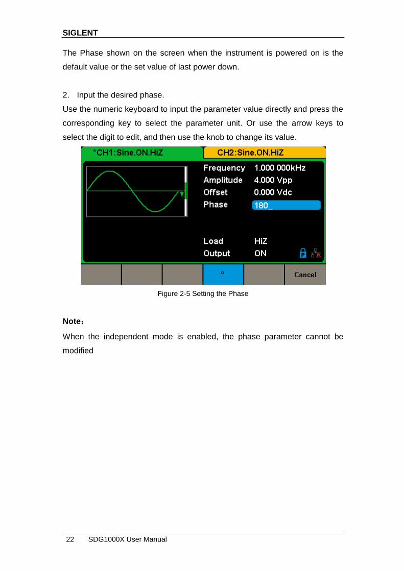
To Set the Phase
1. Press Waveforms → Sine → Phase, to set the phase.
SIGLENT
22 SDG1000X User Manual
The Phase shown on the screen when the instrument is powered on is the
default value or the set value of last power down.
2. Input the desired phase.
Use the numeric keyboard to input the parameter value directly and press the
corresponding key to select the parameter unit. Or use the arrow keys to
select the digit to edit, and then use the knob to change its value.
Figure 2-5 Setting the Phase
Note:
When the independent mode is enabled, the phase parameter cannot be
modified

SIGLENT
SDG1000X User Manual 23
2.2 To Set Square Waveform
Press Waveforms key to select the waveform function, and press the Square
softkey. The square waveform parameters are set by using the Square
operation menu.
The parameters of square waveforms include frequency/period,
amplitude/high level, offset/low level, phase and duty. As shown in Figure 2-6,
select DutyCycle. The duty cycle parameter area is highlighted in the
parameter display window, and users can set the duty cycle value here.
Figure 2-6 Square Parameters Display Interface
Table2-2 Menu Explanations of Square Waveform
Function Menu
Settings Explanation
Frequency/ Period
Set the signal frequency or period; The current parameter will be switched at a second press.
Amplitude/ HighLevel
Set the signal amplitude or high level; The current parameter will be switched at a second press.
Offset/ LowLevel
Set the signal offset or low level; The current parameter will be switched at a second press.
Phase Set the phase of the signal.
DutyCycle Set the duty cycle for square waveform.

SIGLENT
24 SDG1000X User Manual
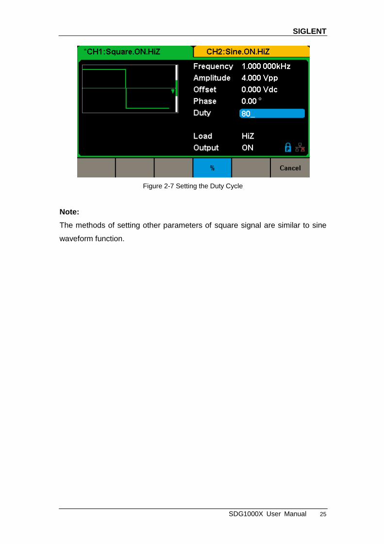
To Set the Duty Cycle
Duty Cycle: The ratio of the amount of time the pulse is in the high state and
the waveform‘s period.
The duty cycle setting range is limited by the ―Frequency/Period‖ setting. For
detailed information, please refer to ―SDG1000X Datasheet‖. The default
value is 50%.
1. Press Waveforms → Square → DutyCycle, to set the duty cycle.
The duty cycle shown on the screen when the instrument is powered on is the
default value or the set value of last power down.
2. Input the desired Duty Cycle.
Use the numeric keyboard to input the parameter value directly and press the
corresponding key to select the parameter unit. Or use the arrow keys to
select the digit to edit, and then use the knob to change its value. The
generator will change the waveform immediately.
SIGLENT
SDG1000X User Manual 25
Figure 2-7 Setting the Duty Cycle
Note:
The methods of setting other parameters of square signal are similar to sine
waveform function.
SIGLENT
26 SDG1000X User Manual
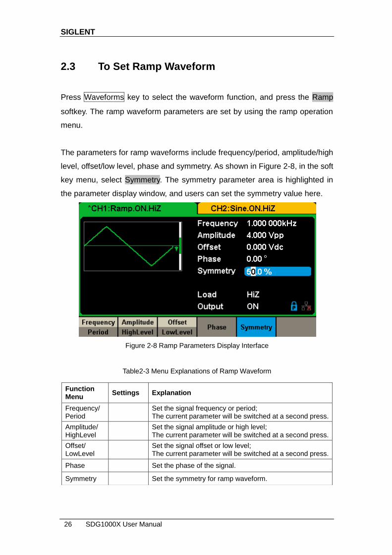
2.3 To Set Ramp Waveform
Press Waveforms key to select the waveform function, and press the Ramp
softkey. The ramp waveform parameters are set by using the ramp operation
menu.
The parameters for ramp waveforms include frequency/period, amplitude/high
level, offset/low level, phase and symmetry. As shown in Figure 2-8, in the soft
key menu, select Symmetry. The symmetry parameter area is highlighted in
the parameter display window, and users can set the symmetry value here.
Figure 2-8 Ramp Parameters Display Interface
Table2-3 Menu Explanations of Ramp Waveform
Function Menu
Settings Explanation
Frequency/ Period
Set the signal frequency or period; The current parameter will be switched at a second press.
Amplitude/ HighLevel
Set the signal amplitude or high level; The current parameter will be switched at a second press.
Offset/ LowLevel
Set the signal offset or low level; The current parameter will be switched at a second press.
Phase Set the phase of the signal.
Symmetry Set the symmetry for ramp waveform.

SIGLENT
SDG1000X User Manual 27
To Set the Symmetry
Symmetry: The percentage that the rising period takes up the whole Period.
Input Range: 0~100%
Default Value: 50%
1. Press Waveforms → Ramp → Symmetry, to set the symmetry.
The symmetry shown on the screen when the instrument is powered on is the
default value or the set value of last power down.
2. Input the desired Symmetry.
Use the numeric keyboard to input the parameter value directly, and press the
corresponding key to select the parameter unit. Or use the arrow keys to
select the digit to edit, and then use the knob to change its value. The
generator will change the waveform immediately.
Figure 2-9 Setting the Symmetry
Note:
The methods of setting other parameters of ramp signal are similar to sine
waveform function.

SIGLENT
28 SDG1000X User Manual
2.4 To Set Pulse Waveform
Press Waveforms key to select the waveform function, and press the Pulse
softkey. The pulse waveform parameters are set by using the pulse operation
menu.
The parameters for pulse waveforms include frequency/period, amplitude/high
level, offset/low level, width, rise/fall and delay. As shown in Figure 2-10, in the
soft key menu, select PulWidth. The pulse width parameter area is highlighted
in the parameter display window, and users can set the pulse width value
here.
Figure 2-10 Pulse Parameters Display Interface
Table 2-4 Menu Explanations of Pulse Waveform
Function Menu
Settings Explanation
Frequency/ Period
Set the signal frequency or period; The current parameter will be switched at a second press.
Amplitude/ HighLevel
Set the signal amplitude or high level; The current parameter will be switched at a second press.
Offset/ LowLevel
Set the signal offset or low level; The current parameter will be switched at a second press.
PulWidth/ DutyCycle
Set the signal pulse width or duty cycle; The current parameter will be switched at a second press.
Rise/ Fall
Setting the rise edge or fall edge for pulse waveform. The current parameter will be switched at a second press.
SIGLENT
SDG1000X User Manual 29
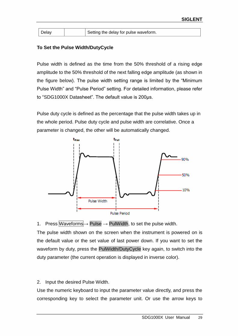
To Set the Pulse Width/DutyCycle
Pulse width is defined as the time from the 50% threshold of a rising edge
amplitude to the 50% threshold of the next falling edge amplitude (as shown in
the figure below). The pulse width setting range is limited by the ―Minimum
Pulse Width‖ and ―Pulse Period‖ setting. For detailed information, please refer
to ―SDG1000X Datasheet‖. The default value is 200μs.
Pulse duty cycle is defined as the percentage that the pulse width takes up in
the whole period. Pulse duty cycle and pulse width are correlative. Once a
parameter is changed, the other will be automatically changed.
1. Press Waveforms→ Pulse → PulWidth, to set the pulse width.
The pulse width shown on the screen when the instrument is powered on is
the default value or the set value of last power down. If you want to set the
waveform by duty, press the PulWidth/DutyCycle key again, to switch into the
duty parameter (the current operation is displayed in inverse color).
2. Input the desired Pulse Width.
Use the numeric keyboard to input the parameter value directly, and press the
corresponding key to select the parameter unit. Or use the arrow keys to
Delay Setting the delay for pulse waveform.

SIGLENT
30 SDG1000X User Manual
select the digit to edit, and then use the knob to change its value. The
generator will change the waveform immediately.
Figure 2-11 Setting the Pulse Width
To Set the Rise/Fall Edge
Rise edge time is defined as the duration of the pulse amplitude rising from 10%
to 90% threshold, while fall edge time is defined as duration of the pulse
amplitude moving down from 90% to 10% threshold. The setting of rise/fall
edge time is limited by the currently specified pulse width limit. Users can set
rise edge and fall edge independently.
1. Press Waveforms → Pulse → Rise to set the rise edge.
The rise edge shown on the screen when the instrument is powered on is the
default value or the set value of last power down. If you want to set the
waveform by fall edge, press the Rise/Fall key again, to switch into the fall
edge parameter (the current operation is displayed in inverse color).
2. Input the desired rise edge.
Use the numeric keyboard to input the parameter value directly, and press the
corresponding key to select the parameter unit. Or use the arrow keys to

SIGLENT
SDG1000X User Manual 31
select the digit to edit, and then use the knob to change its value. The
generator will change the waveform immediately.
Figure 2-12 Setting the Rise Edge
Note:
The methods of setting other parameters of pulse signal are similar to sine
waveform function.
SIGLENT
32 SDG1000X User Manual
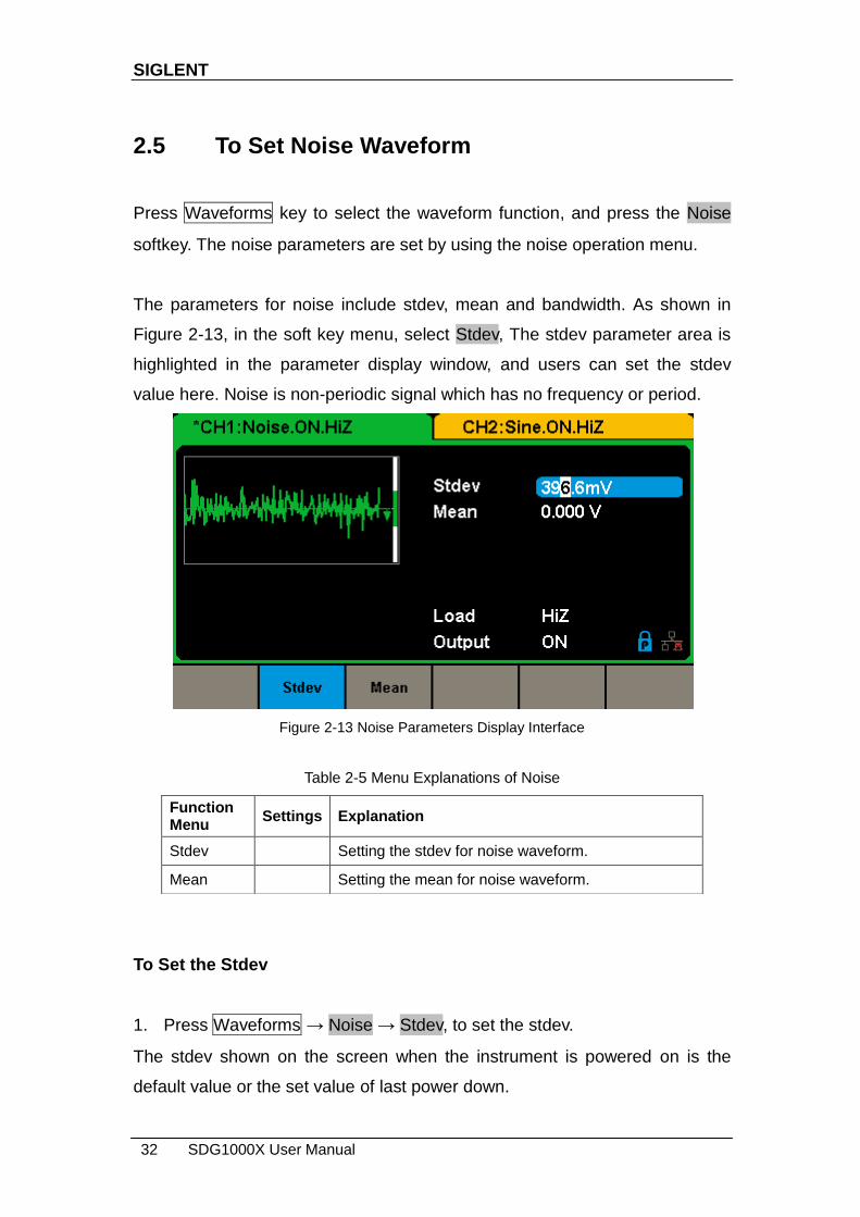
2.5 To Set Noise Waveform
Press Waveforms key to select the waveform function, and press the Noise
softkey. The noise parameters are set by using the noise operation menu.
The parameters for noise include stdev, mean and bandwidth. As shown in
Figure 2-13, in the soft key menu, select Stdev, The stdev parameter area is
highlighted in the parameter display window, and users can set the stdev
value here. Noise is non-periodic signal which has no frequency or period.
Figure 2-13 Noise Parameters Display Interface
Table 2-5 Menu Explanations of Noise
To Set the Stdev
1. Press Waveforms → Noise → Stdev, to set the stdev.
The stdev shown on the screen when the instrument is powered on is the
default value or the set value of last power down.
Function Menu
Settings Explanation
Stdev Setting the stdev for noise waveform.
Mean Setting the mean for noise waveform.
SIGLENT
SDG1000X User Manual 33
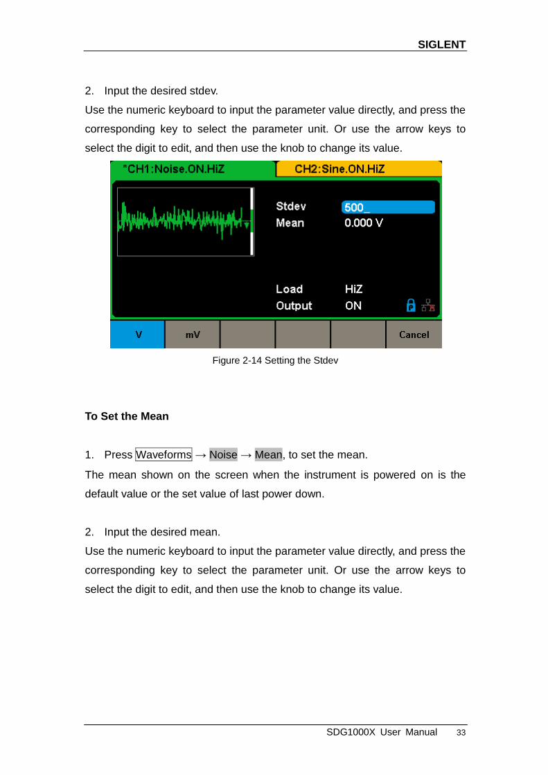
2. Input the desired stdev.
Use the numeric keyboard to input the parameter value directly, and press the
corresponding key to select the parameter unit. Or use the arrow keys to
select the digit to edit, and then use the knob to change its value.
Figure 2-14 Setting the Stdev
To Set the Mean
1. Press Waveforms → Noise → Mean, to set the mean.
The mean shown on the screen when the instrument is powered on is the
default value or the set value of last power down.
2. Input the desired mean.
Use the numeric keyboard to input the parameter value directly, and press the
corresponding key to select the parameter unit. Or use the arrow keys to
select the digit to edit, and then use the knob to change its value.

SIGLENT
34 SDG1000X User Manual
Figure 2-15 Setting the Mean

SIGLENT
SDG1000X User Manual 35
2.6 To Set DC Waveform
Press Waveforms → Page 1/2 → DC, to enter the following interface. Please
note that there is a ‗DC offset‘ parameter at the middle of the screen.
Figure 2-16 DC Setting Interface
Note:
The method of setting offset of DC signal is similar to sine waveform function.
SIGLENT
36 SDG1000X User Manual
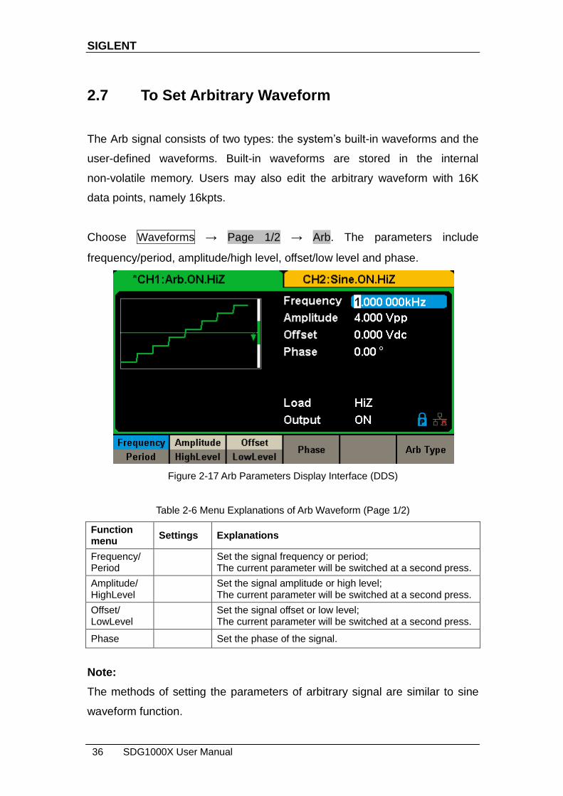
2.7 To Set Arbitrary Waveform
The Arb signal consists of two types: the system‘s built-in waveforms and the
user-defined waveforms. Built-in waveforms are stored in the internal
non-volatile memory. Users may also edit the arbitrary waveform with 16K
data points, namely 16kpts.
Choose Waveforms → Page 1/2 → Arb. The parameters include
frequency/period, amplitude/high level, offset/low level and phase.
Figure 2-17 Arb Parameters Display Interface (DDS)
Table 2-6 Menu Explanations of Arb Waveform (Page 1/2)
Function menu
Settings Explanations
Frequency/ Period
Set the signal frequency or period; The current parameter will be switched at a second press.
Amplitude/ HighLevel
Set the signal amplitude or high level; The current parameter will be switched at a second press.
Offset/ LowLevel
Set the signal offset or low level; The current parameter will be switched at a second press.
Phase Set the phase of the signal.
Note:
The methods of setting the parameters of arbitrary signal are similar to sine
waveform function.
SIGLENT
SDG1000X User Manual 37
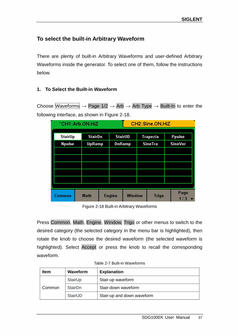
To select the built-in Arbitrary Waveform
There are plenty of built-in Arbitrary Waveforms and user-defined Arbitrary
Waveforms inside the generator. To select one of them, follow the instructions
below.
1. To Select the Built-in Waveform
Choose Waveforms → Page 1/2 → Arb → Arb Type → Built-In to enter the
following interface, as shown in Figure 2-18.
Figure 2-18 Built-in Arbitrary Waveforms
Press Common, Math, Engine, Window, Trigo or other menus to switch to the
desired category (the selected category in the menu bar is highlighted), then
rotate the knob to choose the desired waveform (the selected waveform is
highlighted). Select Accept or press the knob to recall the corresponding
waveform.
Table 2-7 Built-in Waveforms
Item Waveform Explanation
Common
StairUp Stair-up waveform
StairDn Stair-down waveform
StairUD Stair-up and down waveform
SIGLENT
38 SDG1000X User Manual
Trapezia Trapezia waveform
Ppulse Positive pulse
Npulse Negative pulse
UpRamp UpRamp waveform
DnRamp DnRamp waveform
SineTra Sine-Tra waveform
SineVer Sine-Ver waveform
Math
ExpFall ExpFall function
ExpRise ExpRise function
LogFall LogFall function
LogRise LogRise function
Sqrt Sqrt function
Root3 Root3 function
X^2 X2 function
X^3 X3 function
Airy Airy function
Besselj Bessel I function
Bessely Bessel II function
Dirichlet Dirichlet function
Erf Error function
Erfc Complementary error function
ErfcInv Inverted complementary error function
ErfInv Inverted error function
Laguerre 4-times Laguerre polynomial
Legend 5-times Legend polynomial
Versiera Versiera
Sinc Sinc function
Gaussian Gaussian function
Dlorentz Dlorentz function
Haversine Haversine function
Lorentz Lorentz function
Gauspuls Gauspuls signal
Gmonopuls Gmonopuls signal
Tripuls Tripuls signal
Weibull Weibull distribution

SIGLENT
SDG1000X User Manual 39
LogNormal LogNormal Gaussian distribution
Laplace Laplace distribution
Maxwell Maxwell distribution
Rayleigh Rayleigh distribution
Cauchy Cauchy distribution
Engine
Cardiac Cardiac signal
Quake Analog quake waveform
Chirp Chirp signal
TwoTone TwoTone signal
SNR SNR signal
AmpALT Gain oscillation curve
AttALT Attenuation oscillation curve
RoundHalf RoundHalf Waveform
RoundsPM RoundsPM Waveform
BlaseiWave Time-velocity curve of explosive oscillation
DampedOsc Time-displacement curve of damped oscillation
SwingOsc Kinetic energy – time curve of swing oscillation
Discharge Discharge curve of NI-MH battery
Pahcur Current waveform of DC brushless motor
Combin Combination function
SCR SCR firing profile
TV TV signal
Voice Voice signal
Surge Surge signal
Radar Analog radar signal
Ripple Ripple wave of battery
Gamma Gamma signal
StepResp Step-response signal
BandLimited Bandwidth-limited signal
CPulse C-Pulse
CWPulse CW pulse
GateVibr Gate self-oscillation signal
LFMPulse Linear FM pulse
MCNoise Mechanical construction noise
Window Hamming Hamming window

SIGLENT
40 SDG1000X User Manual
Hanning Hanning window
Kaiser Kaiser window
Blackman Blackman window
GaussiWin GaussiWin window
Triangle Triangle window (Fejer window)
BlackmanH BlackmanH window
Bartlett-Hann Bartlett-Hann window
Bartlett Bartlett window
BarthannWin Modified Bartlett-Hann window
BohmanWin BohmanWin window
ChebWin ChebWin window
FlattopWin Flat top weighted window
ParzenWin ParzenWin window
TaylorWin TaylorWin window
TukeyWin TukeyWin (tapered cosine) window
Trigo
Tan Tangent
Cot Cotangent
Sec Secant
Csc Cosecant
Asin Arc sine
Acos Arc cosine
Atan Arc tangent
ACot Arc cotangent
CosH Hyperbolic cosine
CosInt Integral cosine
Coth Hyperbolic cotangent
Csch Hyperbolic cosecant
SecH Hyperbolic secant
SinH Hyperbolic sine
SinInt Integral sine
TanH Hyperbolic tangent
ACosH Arc hyperbolic cosine
ASecH Arc hyperbolic secant
ASinH Arc hyperbolic sine
ATanH Arc hyperbolic tangent
SIGLENT
SDG1000X User Manual 41
ACsch Arc hyperbolic cosecant
ACoth Arc hyperbolic cotangent
Square 1
SquareDuty01 Square waveform with 1% duty
SquareDuty02 Square waveform with 2% duty
SquareDuty04 Square waveform with 4% duty
SquareDuty06 Square waveform with 6% duty
SquareDuty08 Square waveform with 8% duty
SquareDuty10 Square waveform with 10% duty
SquareDuty12 Square waveform with 12% duty
SquareDuty14 Square waveform with 14% duty
SquareDuty16 Square waveform with 16% duty
SquareDuty18 Square waveform with 18% duty
SquareDuty20 Square waveform with 20% duty
SquareDuty22 Square waveform with 22% duty
SquareDuty24 Square waveform with 24% duty
SquareDuty26 Square waveform with 26% duty
SquareDuty28 Square waveform with 28% duty
SquareDuty30 Square waveform with 30% duty
SquareDuty32 Square waveform with 32% duty
SquareDuty34 Square waveform with 34% duty
SquareDuty36 Square waveform with 36% duty
SquareDuty38 Square waveform with 38% duty
SquareDuty40 Square waveform with 40% duty
SquareDuty42 Square waveform with 42% duty
SquareDuty44 Square waveform with 44% duty
SquareDuty46 Square waveform with 46% duty
SquareDuty48 Square waveform with 48% duty
SquareDuty50 Square waveform with 50% duty
SquareDuty52 Square waveform with 52% duty
SquareDuty54 Square waveform with 54% duty
SquareDuty56 Square waveform with 56% duty
SquareDuty58 Square waveform with 58% duty
SquareDuty60 Square waveform with 60% duty
SquareDuty62 Square waveform with 62% duty
SquareDuty64 Square waveform with 64% duty
SIGLENT
42 SDG1000X User Manual
SquareDuty66 Square waveform with 66% duty
SquareDuty68 Square waveform with 68% duty
Square 2
SquareDuty70 Square waveform with 70% duty
SquareDuty72 Square waveform with 72% duty
SquareDuty74 Square waveform with 74% duty
SquareDuty76 Square waveform with 76% duty
SquareDuty78 Square waveform with 78% duty
SquareDuty80 Square waveform with 80% duty
SquareDuty82 Square waveform with 82% duty
SquareDuty84 Square waveform with 84% duty
SquareDuty86 Square waveform with 86% duty
SquareDuty88 Square waveform with 88% duty
SquareDuty90 Square waveform with 90% duty
SquareDuty92 Square waveform with 92% duty
SquareDuty94 Square waveform with 94% duty
SquareDuty96 Square waveform with 96% duty
SquareDuty98 Square waveform with 98% duty
SquareDuty99 Square waveform with 99% duty
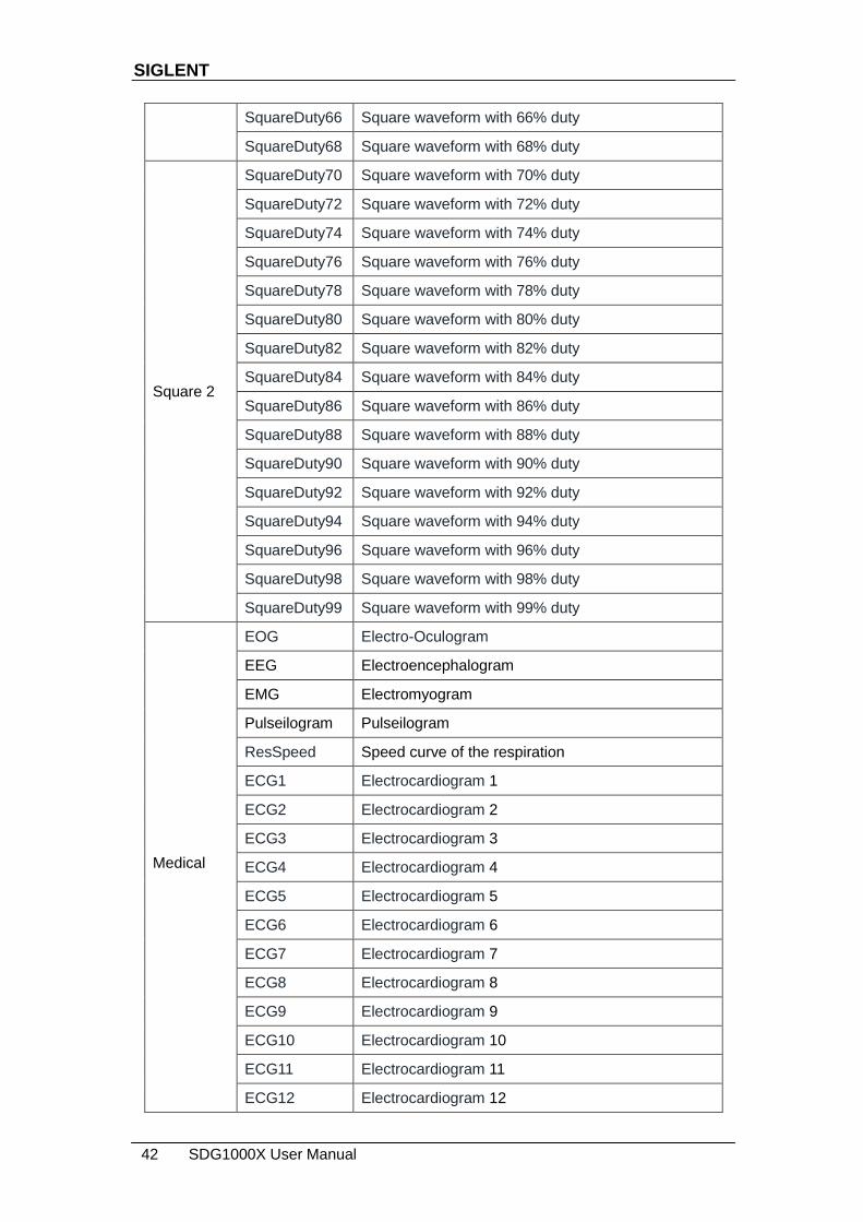
Medical
EOG Electro-Oculogram
EEG Electroencephalogram
EMG Electromyogram
Pulseilogram Pulseilogram
ResSpeed Speed curve of the respiration
ECG1 Electrocardiogram 1
ECG2 Electrocardiogram 2
ECG3 Electrocardiogram 3
ECG4 Electrocardiogram 4
ECG5 Electrocardiogram 5
ECG6 Electrocardiogram 6
ECG7 Electrocardiogram 7
ECG8 Electrocardiogram 8
ECG9 Electrocardiogram 9
ECG10 Electrocardiogram 10
ECG11 Electrocardiogram 11
ECG12 Electrocardiogram 12

SIGLENT
SDG1000X User Manual 43
ECG13 Electrocardiogram 13
ECG14 Electrocardiogram 14
ECG15 Electrocardiogram 15
LFPulse Waveform of the low frequency pulse electrotherapy
Tens1 Waveform 1 of the nerve stimulation electrotherapy
Tens2 Waveform 2 of the nerve stimulation electrotherapy
Tens3 Waveform 3 of the nerve stimulation electrotherapy
Mod
AM Sectional sine AM signal
FM Sectional sine FM signal
PFM Sectional pulse FM signal
PM Sectional sine PM signal l
PWM Sectional PWM signal
Filter
Butterworth Butterworth filter
Chebyshev1 Chebyshev1 filter
Chebyshev2 Chebyshev2 filter
Demo
demo1_375pts TureArb waveform 1(375 pts)
demo1_16kpts TureArb waveform 1(16384 pts)
demo2_3kpts TureArb waveform 2(3000 pts)
demo2_16kpts TureArb waveform 2(16384 pts)
2. To Select the Stored Waveform
Choose Waveforms → Page 1/2 → Arb → Arb Type → Stored Waveforms to
enter the following interface, as shown in Figure 2-19.

SIGLENT
44 SDG1000X User Manual
Figure 2-19 Stored Waveform Display Interface
Rotate the knob to choose the desired waveform. Then select Recall or press
the knob to recall the corresponding waveform.
SIGLENT
SDG1000X User Manual 45
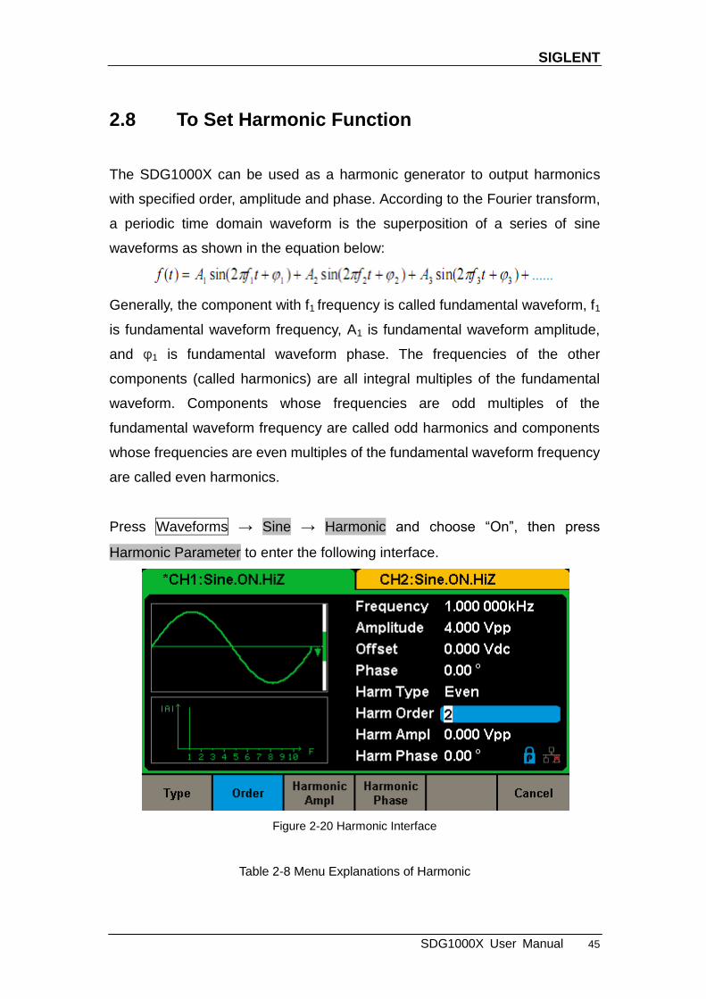
2.8 To Set Harmonic Function
The SDG1000X can be used as a harmonic generator to output harmonics
with specified order, amplitude and phase. According to the Fourier transform,
a periodic time domain waveform is the superposition of a series of sine
waveforms as shown in the equation below:
Generally, the component with f1 frequency is called fundamental waveform, f1
is fundamental waveform frequency, A1 is fundamental waveform amplitude,
and φ1 is fundamental waveform phase. The frequencies of the other
components (called harmonics) are all integral multiples of the fundamental
waveform. Components whose frequencies are odd multiples of the
fundamental waveform frequency are called odd harmonics and components
whose frequencies are even multiples of the fundamental waveform frequency
are called even harmonics.
Press Waveforms → Sine → Harmonic and choose ―On‖, then press
Harmonic Parameter to enter the following interface.
Figure 2-20 Harmonic Interface
Table 2-8 Menu Explanations of Harmonic

SIGLENT
46 SDG1000X User Manual
Function menu
Settings Explanations
Type Set the harmonic type to ―odd‖, ―ever‖ or ―all‖.
Order Set the order of the harmonic.
Harmonic Ampl
Set the amplitude of the harmonic.
Harmonic Phase
Set the phase of the harmonic.
Cancel Return to the sine parameters menu.
To Select the Harmonic Type
The SDG1000X can output odd harmonics, ever harmonics and user-defined
orders of harmonics. After entering the harmonic setting menu, press Type to
select the desired harmonic type.
1. Press Even, the instrument will output fundamental waveform and even
harmonics.
2. Press Odd, the instrument will output fundamental waveform and odd
harmonics.
3. Press All, the instrument will output fundamental waveform and all the
user-defined orders of harmonics.
To Set the Harmonic Order
After entering the harmonic setting menu, press Order, the use the numeric
keyboard or knob to input the desired value.
The range is limited by the maximum output frequency of the instrument
and current fundamental waveform frequency.
Range: 2 to maximum output frequency of the instrument ÷ current
fundamental waveform frequency
The maximum is 10.
To Select the Harmonic Amplitude
After entering the harmonic setting menu, press Harmonic Ampl to set the
harmonic amplitude of each order.
1. Press Order to select the sequence number of the harmonic to be set.
SIGLENT
SDG1000X User Manual 47
2. Press Harmonic Ampl to set the amplitude of the harmonic selected. Use
the arrow keys and knob to change the value. Or use the numeric
keyboard to input the amplitude value and then select the desired unit from
the pop-up menu. The units available are Vpp, mVpp and dBc.
To Select the Harmonic Phase
After entering the harmonic setting menu, press Harmonic Phase to set the
harmonic phase of each order.
1. Press Order to select the sequence number of the harmonic to be set.
2. Press Harmonic Phase to set the phase of the harmonic selected. Use the
arrow keys and knob to change the value. Or use the numeric keyboard to
input the phase value and then select the unit °.
SIGLENT
48 SDG1000X User Manual
2.9 To Set Modulation Function
Use the Mod key to generate modulated waveforms. The SDG1000X can
generate AM, FM, ASK, FSK, PSK, PM, PWM and DSB-AM modulated
waveforms. Modulating parameters vary with the types of the modulation. In
AM, users can set the source (internal/external), depth, modulating frequency,
modulating waveform and carrier. In DSB-AM, users can set the source
(internal/external), modulating frequency, modulating waveform and carrier. In
FM, users can set the source (internal/external), modulating frequency,
frequency deviation, modulating waveform and carrier. In PM, users can set
the source (internal/external), phase deviation, modulating frequency,
modulating waveform and carrier. In ASK, users can set the source
(internal/external), key frequency and carrier. In FSK, users can set the source
(internal/external), key frequency, hop frequency and carrier. In PSK, users
can set the source (internal/external), key frequency, polarity and carrier. In
PWM, users can set the source (internal/external), modulating frequency,
width/duty cycle deviation, modulating waveform and carrier.
We will introduce how to set these parameters in details according to the
modulation types.

SIGLENT
SDG1000X User Manual 49
2.9.1 AM
The modulated waveform consists of two parts: the carrier and the modulating
waveform. In AM, the amplitude of the carrier varies with the instantaneous
voltage of the modulating waveform.
Press Mod → Type → AM, the parameters of AM modulation are shown in
Figure 2-21.
Figure 2-21 Setting Interface of AM Modulation
Table 2-9 Menu Explanations of the AM Parameters
Function Menu
Settings Explanation
Type AM Amplitude modulation
Source
Internal The source is internal
External The source is external. Use the [Aux In/Out] connector at the rear panel.
AM Depth Set the modulation depth.
Shape
Sine
Choose the modulating waveform.
Square
Triangle
UpRamp
DnRamp
Noise

SIGLENT
50 SDG1000X User Manual
Arb
AM Freq Set the modulating waveform frequency. Frequency range: 1mHz~20kHz (internal source only).
To Select Modulation Source
The SDG1000X can accept modulating signal from an internal or external
modulation source. Press Mod → AM → Source to select ―Internal‖ or
―External‖ modulation source. The default is ―Internal‖.
1. Internal Source
When internal AM modulation source is selected, press Shape to select Sine,
Square, Triangle, UpRamp, DnRamp, Noise or Arb as modulating waveform.
Square: 50% duty cycle
Triangle: 50% symmetry
UpRamp: 100% symmetry
DnRamp: 0% symmetry
Arb: the arbitrary waveform selected of the current channel
Note:
Noise can be used as modulating waveform but cannot be used as the carrier.
2. External Source
When external AM modulation source is selected, the generator accepts
external modulating signal from the [Aux In/Out] connector at the rear panel.
At this time, the amplitude of the modulated waveform is controlled by the
signal level applied to the connector. For example, if the modulation depth is
set to 100%, the output amplitude will be the maximum when the modulating
signal is +6V and the minimum when the modulating signal is -6V.
Key Points:
The SDG1000X can use one channel as a modulating source for the other
channel. The following example takes the output signal of CH2 as the
modulating waveform.
1. Connect the CH2 output terminal to [Aux In/Out] connector on the rear
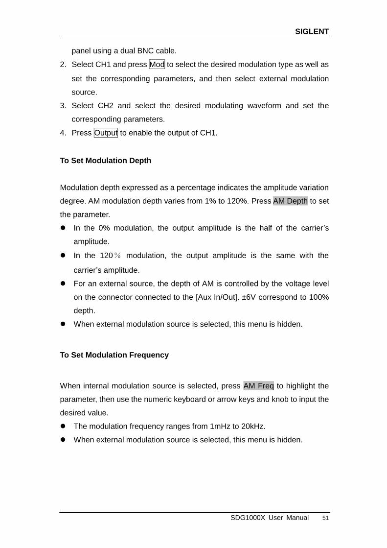
SIGLENT
SDG1000X User Manual 51
panel using a dual BNC cable.
2. Select CH1 and press Mod to select the desired modulation type as well as
set the corresponding parameters, and then select external modulation
source.
3. Select CH2 and select the desired modulating waveform and set the
corresponding parameters.
4. Press Output to enable the output of CH1.
To Set Modulation Depth
Modulation depth expressed as a percentage indicates the amplitude variation
degree. AM modulation depth varies from 1% to 120%. Press AM Depth to set
the parameter.
In the 0% modulation, the output amplitude is the half of the carrier‘s
amplitude.
In the 120% modulation, the output amplitude is the same with the
carrier‘s amplitude.
For an external source, the depth of AM is controlled by the voltage level
on the connector connected to the [Aux In/Out]. ±6V correspond to 100%
depth.
When external modulation source is selected, this menu is hidden.
To Set Modulation Frequency
When internal modulation source is selected, press AM Freq to highlight the
parameter, then use the numeric keyboard or arrow keys and knob to input the
desired value.
The modulation frequency ranges from 1mHz to 20kHz.
When external modulation source is selected, this menu is hidden.
SIGLENT
52 SDG1000X User Manual
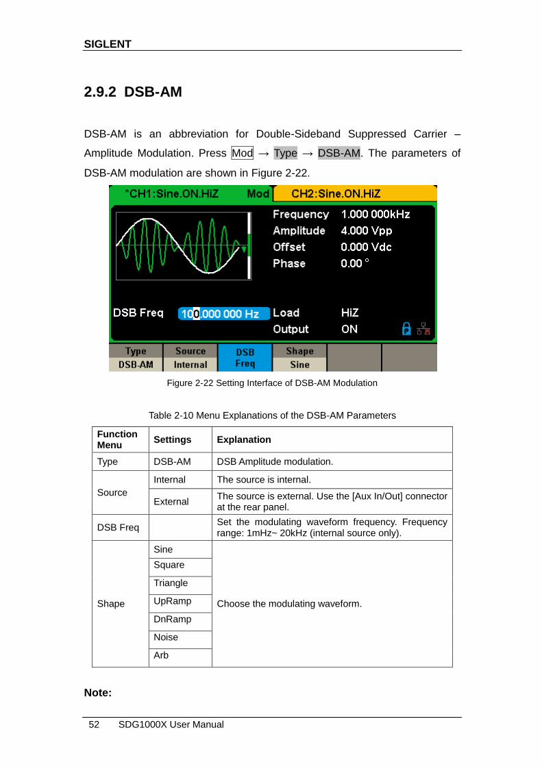
2.9.2 DSB-AM
DSB-AM is an abbreviation for Double-Sideband Suppressed Carrier –
Amplitude Modulation. Press Mod → Type → DSB-AM. The parameters of
DSB-AM modulation are shown in Figure 2-22.
Figure 2-22 Setting Interface of DSB-AM Modulation
Table 2-10 Menu Explanations of the DSB-AM Parameters
Function Menu
Settings Explanation
Type DSB-AM DSB Amplitude modulation.
Source
Internal The source is internal.
External The source is external. Use the [Aux In/Out] connector at the rear panel.
DSB Freq Set the modulating waveform frequency. Frequency range: 1mHz~ 20kHz (internal source only).
Shape
Sine
Choose the modulating waveform.
Square
Triangle
UpRamp
DnRamp
Noise
Arb
Note:

SIGLENT
SDG1000X User Manual 53
The methods of setting the parameters of DSB-AM are similar to AM.
SIGLENT
54 SDG1000X User Manual
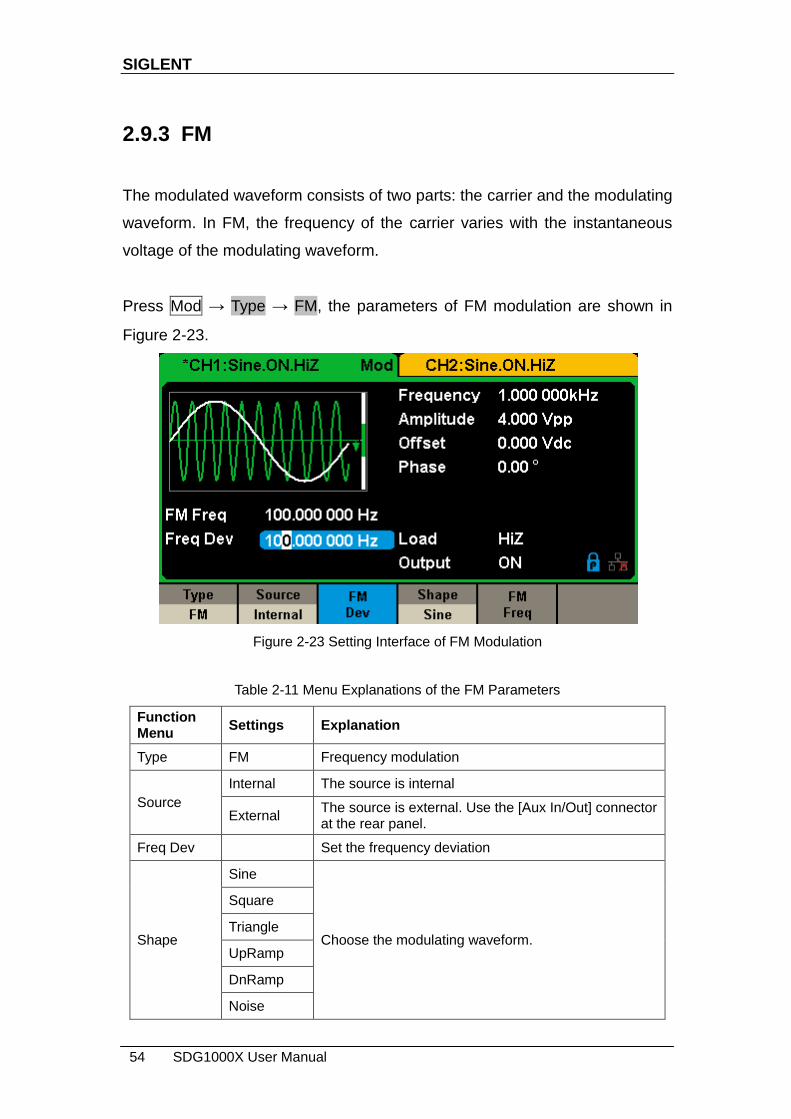
2.9.3 FM
The modulated waveform consists of two parts: the carrier and the modulating
waveform. In FM, the frequency of the carrier varies with the instantaneous
voltage of the modulating waveform.
Press Mod → Type → FM, the parameters of FM modulation are shown in
Figure 2-23.
Figure 2-23 Setting Interface of FM Modulation
Table 2-11 Menu Explanations of the FM Parameters
Function Menu
Settings Explanation
Type FM Frequency modulation
Source
Internal The source is internal
External The source is external. Use the [Aux In/Out] connector at the rear panel.
Freq Dev Set the frequency deviation
Shape
Sine
Choose the modulating waveform.
Square
Triangle
UpRamp
DnRamp
Noise

SIGLENT
SDG1000X User Manual 55
Arb
FM Freq Set the modulating waveform frequency. Frequency range 1mHz~ 20kHz (internal source).
To Set Frequency Deviation
Press FM Dev to highlight the parameter, and then use the numeric keyboard
or arrow keys and knob to input the desired value.
The deviation should be equal to or less than the carrier frequency.
The sum of the deviation and the carrier frequency should be equal to or
less than maximum frequency of the selected carrier waveform.
Note:
The methods of setting other parameters of FM are similar to AM.

SIGLENT
56 SDG1000X User Manual
2.9.4 PM
The modulated waveform consists of two parts: the carrier and the modulating
waveform. In PM, the phase of the carrier varies with the instantaneous
voltage level of the modulating waveform.
Press Mod → Type → PM, the parameters of PM modulation are shown in
Figure 2-24.
Figure 2-24 Setting Interface of PM Modulation
Table 2-12 Menu Explanations of the PM Parameters
Function Menu
Settings Explanation
Type PM Phase modulation
Source
Internal The source is internal
External The source is external. Use the [Aux In/Out] connector at the rear panel.
Phase Dev Phase deviation ranges from 0° ~ 360°.
Shape
Sine
Choose the modulating waveform.
Square
Triangle
UpRamp
DnRamp
Noise

SIGLENT
SDG1000X User Manual 57
Arb
PM Freq Set the modulating waveform frequency. Frequency range: 1mHz~ 20kHz.
To Set Phase Deviation
Press Phase Dev to highlight the parameter, and then use the numeric
keyboard or arrow keys and knob to input the desired value.
Use the numeric keyboard or arrow keys and knob to input the desired
value.
The range of phase deviation is from 0° to 360° and the default value is
100°.
Note:
The methods of setting other parameters of PM are similar to AM.

SIGLENT
58 SDG1000X User Manual
2.9.5 FSK
The FSK is Frequency Shift Keying, the output frequency of which switches
between two preset frequencies (carrier frequency and the hop frequency or
sometimes known as mark frequency (1) and space frequency (0)).
Press Mod → Type → FSK, the parameters of FSK modulation are shown in
Figure 2-25.
Figure 2-25 Setting Interface of FSK Modulation
Table 2-13 Menu Explanations of the FSK Parameters
Function Menu
Settings Explanation
Type FSK Frequency shift keying modulation.
Source
Internal The source is internal.
External The source is external. Use the [Aux In/Out] connector at the rear panel.
Key Freq Set the frequency at which the output frequency shifts between the carrier frequency and the hop frequency (internal modulation only): 1mHz~ 50kHz.
Hop Freq Set the hop frequency.
To Set Key Frequency
When internal modulation source is selected, press Key Freq to set the rate at

SIGLENT
SDG1000X User Manual 59
which the output frequency shifts between ―carrier frequency‖ and ―hop
frequency‖.
Use the numeric keyboard or arrow keys and knob to input the desired
value.
The key frequency ranges from 1mHz to 50kHz.
When external modulation source is selected, this menu is hidden.
To Set Hop Frequency
The range of the hop frequency depends on the carrier frequency currently
selected. Press Hop Freq to highlight the parameter, and then use the numeric
keyboard or arrow keys and knob to input the desired value.
Sine: 1uHz~60MHz
Square: 1uHz~25MHz
Ramp: 1uHz~500kHz
Arb: 1uHz~6MHz
Note:
The methods of setting other parameters of FSK are similar to AM. In addition,
the external modulating signal of FSK must be Square which complies with the
CMOS level specification.
SIGLENT
60 SDG1000X User Manual
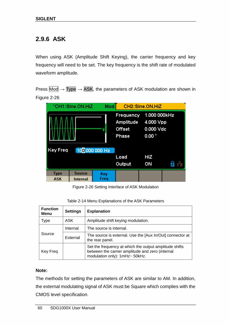
2.9.6 ASK
When using ASK (Amplitude Shift Keying), the carrier frequency and key
frequency will need to be set. The key frequency is the shift rate of modulated
waveform amplitude.
Press Mod → Type → ASK, the parameters of ASK modulation are shown in
Figure 2-26
Figure 2-26 Setting Interface of ASK Modulation
Table 2-14 Menu Explanations of the ASK Parameters
Function Menu
Settings Explanation
Type ASK Amplitude shift keying modulation.
Source
Internal The source is internal.
External The source is external. Use the [Aux In/Out] connector at the rear panel.
Key Freq Set the frequency at which the output amplitude shifts between the carrier amplitude and zero (internal modulation only): 1mHz~ 50kHz.
Note:
The methods for setting the parameters of ASK are similar to AM. In addition,
the external modulating signal of ASK must be Square which complies with the
CMOS level specification.
SIGLENT
SDG1000X User Manual 61
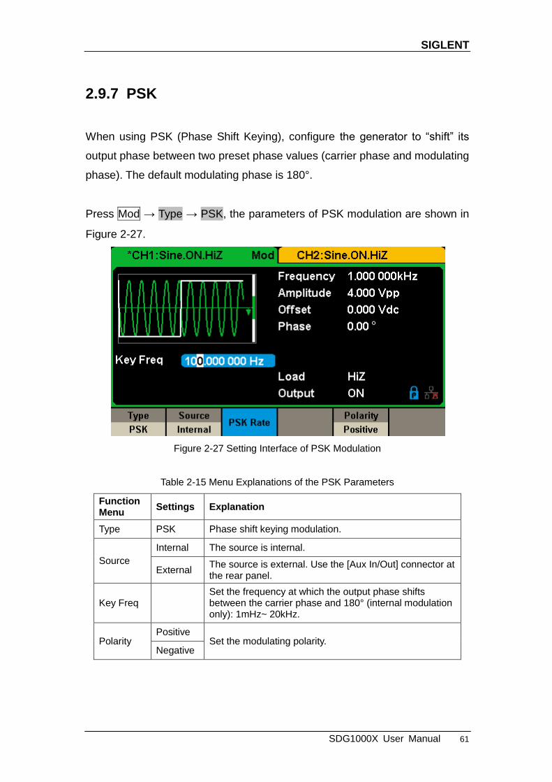
2.9.7 PSK
When using PSK (Phase Shift Keying), configure the generator to ―shift‖ its
output phase between two preset phase values (carrier phase and modulating
phase). The default modulating phase is 180°.
Press Mod → Type → PSK, the parameters of PSK modulation are shown in
Figure 2-27.
Figure 2-27 Setting Interface of PSK Modulation
Table 2-15 Menu Explanations of the PSK Parameters
Function Menu
Settings Explanation
Type PSK Phase shift keying modulation.
Source
Internal The source is internal.
External The source is external. Use the [Aux In/Out] connector at the rear panel.
Key Freq Set the frequency at which the output phase shifts between the carrier phase and 180° (internal modulation only): 1mHz~ 20kHz.
Polarity Positive
Set the modulating polarity. Negative

SIGLENT
62 SDG1000X User Manual
Note:
The methods of setting the parameters of PSK are similar to AM. In addition,
the external modulating signal of PSK must be Square which complies with
the CMOS level specification.

SIGLENT
SDG1000X User Manual 63
2.9.8 PWM
In PWM (Pulse Width Modulation), the pulse width of the pulse varies with the
instantaneous voltage of the modulating waveform. The carrier can only be
pulse.
Press Waveforms → Pulse → Mod, the parameters of PWM modulation are
shown in Figure 2-28.
Figure 2-28 Setting Interface of PWM Modulation
Table 2-16 Menu Explanations of the PWM Parameters
Function Menu
Settings Explanation
Type PWM Pulse width modulation. The carrier is pulse.
Source
Internal The source is internal.
External The source is external. Use the [Aux In/Out] connector at the rear panel.
Width Dev Set the width deviation.
Duty Dev Set the duty deviation.
Shape
Sine
Choose the modulating waveform.
Square
Triangle
UpRamp
DnRamp

SIGLENT
64 SDG1000X User Manual
Noise
Arb
PWM Freq Set the modulating waveform frequency. Frequency range: 1mHz~ 20kHz (internal source only).
To Set Pulse Width/Duty Deviation
Width Deviation represents the variation of the modulated waveform pulse
width relative to the original pulse width. Press Width Dev to highlight the
parameter, and use the numeric keyboard or arrow keys and knob to input the
desired value, as shown in the Figure 2-29.
Figure 2-29 Width Deviation Setting Interface
The width deviation cannot exceed the current pulse width.
The width deviation is limited by the minimum pulse width and current
edge time setting.
Duty Deviation represents the variation (%) of the modulated waveform duty
relative to the original duty. Press Duty Dev to highlight the parameter, and
then use the numeric keyboard or arrow keys and knob to input the desired
value, as shown in the Figure 2-30.
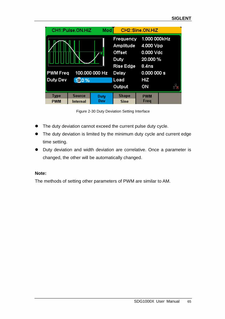
SIGLENT
SDG1000X User Manual 65
Figure 2-30 Duty Deviation Setting Interface
The duty deviation cannot exceed the current pulse duty cycle.
The duty deviation is limited by the minimum duty cycle and current edge
time setting.
Duty deviation and width deviation are correlative. Once a parameter is
changed, the other will be automatically changed.
Note:
The methods of setting other parameters of PWM are similar to AM.

SIGLENT
66 SDG1000X User Manual
2.10 To Set Sweep Function
In the sweep mode, the generator steps from the start frequency to the stop
frequency in the sweep time specified by the user. The waveforms that
support sweep include sine, square, ramp and arbitrary.
Press Sweep key to enter the following menu. Set the waveform parameters
by using the operation menu.
Figure 2-31 Setting Interface of Sweep (Page 1/2)
Table 2-17 Menu Explanations of Sweep (Page 1/2)
Function Menu
Settings Explanation
Sweep time Set the time span of the sweep in which the frequency changes from the start frequency to stop frequency.
Start Freq Mid Freq
Set the start frequency of the sweep; Set the center frequency of the sweep.
Stop Freq Freq Span
Set the stop frequency of the sweep; Set the frequency span of the sweep.
Source
Internal Choose internal source as a trigger.
External Choose external source as a trigger. Use the [Aux In/Out] connector at the rear panel.
Manual Trigger a sweep by manual.
Trig Out Off Disable trigger out.
On Enable trigger out.

SIGLENT
SDG1000X User Manual 67
Figure 2-32 Setting Interface of Sweep (Page 2/2)
Table 2-18 Menu Explanations of Sweep (Page 2/2)
Sweep Frequency
Use start freq and stop freq or center freq and freq span to set the range of the
frequency sweep. Press the key again to switch between the two sweep range
modes.
.
Start Frequency and Stop Frequency
Start Frequency and Stop Frequency are the lower and upper limits of the
frequency for sweep. Start Frequency ≤ Stop Frequency.
Page 1/2
Enter the next page.
Function Menu
Settings Explanation
Type Linear Set the sweep with linear profile.
Log Set the sweep with logarithmic profile.
Direction Up Sweep upward.
Down Sweep downward.
Page 2/2
Return to the previous page.
SIGLENT
68 SDG1000X User Manual
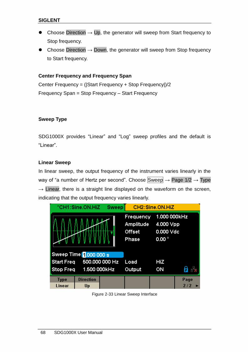
Choose Direction → Up, the generator will sweep from Start frequency to
Stop frequency.
Choose Direction → Down, the generator will sweep from Stop frequency
to Start frequency.
Center Frequency and Frequency Span
Center Frequency = (|Start Frequency + Stop Frequency|)/2
Frequency Span = Stop Frequency – Start Frequency
Sweep Type
SDG1000X provides ―Linear‖ and ―Log‖ sweep profiles and the default is
―Linear‖.
Linear Sweep
In linear sweep, the output frequency of the instrument varies linearly in the
way of ―a number of Hertz per second‖. Choose Sweep → Page 1/2 → Type
→ Linear, there is a straight line displayed on the waveform on the screen,
indicating that the output frequency varies linearly.
Figure 2-33 Linear Sweep Interface

SIGLENT
SDG1000X User Manual 69
Log Sweep
In log sweep, the output frequency of the instrument varies in a logarithmic
fashion, that is, the output frequency changes in the way of ―decade per
second‖. Choose Sweep → Page 1/2 → Type → Log, there is an exponential
function curve displayed on the waveform on the screen, indicating that the
output frequency changes in a logarithmic mode.
Figure 2-34 Log Sweep Interface
Sweep Trigger Source
The sweep trigger source can be internal, external or manual. The generator
will generate a sweep output when a trigger signal is received and then wait
for the next trigger source.
1. Internal Trigger
Choose Source → Internal, the generator outputs continuous sweep
waveform when internal trigger is selected. The default is ―Internal‖. Choose
Trig Out → On, the [Aux In/Out] connector at the rear panel will output the
trigger signal.
2. External Trigger
Choose Source → External, the generator accepts the trigger signal inputted
SIGLENT
70 SDG1000X User Manual
from the [Aux In/Out] connector at the rear panel when external trigger is
selected. A sweep will be generated once the connector receives a CMOS
pulse with specified polarity. To set the CMOS pulse polarity, choose Edge to
select ―Up‖ or ―Down‖.
3. Manual Trigger
Choose Source → Manual, a sweep will be generated from the corresponding
channel when the Trigger softkey is pressed when manual trigger is selected.
Choose Trig Out → On, the [Aux In/Out] connector at the rear panel will output
the trigger signal.
SIGLENT
SDG1000X User Manual 71
2.11 To Set Burst Function
The Burst function can generate versatile waveforms in n this mode. Burst
times can last a specific number of waveform cycles (N-Cycle mode), or when
an external gated signals (Gated mode) is applied. Any waveform (except DC)
may be used as the carrier, but noise can only be used in Gated mode.
Burst Type
SDG1000X provides three burst types including N-Cycle, Infinite and Gated.
The default is N-Cycle.
Table 2-19 Relations among burst type, trigger source and carrier
Burst Type Trigger Source Carrier
N-Cycle Internal/External/Manual
Sine, Square, Ramp, Pulse, Arbitrary.
Infinite External/Manual Sine, Square, Ramp, Pulse, Arbitrary.
Gated Internal/External Sine, Square, Ramp, Pulse, Noise, Arbitrary.
N-Cycle
In N-Cycle mode, the generator will output waveform with a specified number
of cycles after receiving the trigger signal. Waveforms that support N-Cycle
burst include sine, square, ramp, pulse and arbitrary.
Press Burst → NCycle → Cycles, and use the numeric keyboard or arrow
keys and knob to input the desired cycles. Set the waveform parameters by
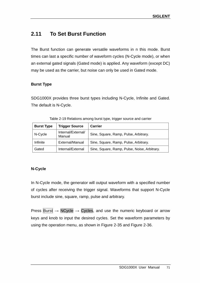
using the operation menu, as shown in Figure 2-35 and Figure 2-36.
SIGLENT
72 SDG1000X User Manual
Figure 2-35 N-Cycle Burst Interface (Page 1/2)
Table 2-20 Menu Explanations of the N-Cycle Burst (Page 1/2)
Function Menu
Settings Explanation
NCycle Use the N-Cycle mode.
Cycles Infinite
Set the number of the bursts in N-Cycle. Set the number of the bursts in N-Cycle to be infinite.
Start Phase Set the start phase of the burst.
Burst Period Set the burst period.
Source
Internal Choose internal source as a trigger.
External Choose external source as a trigger. Use the [Aux In/Out] connector at the rear panel.
Manual Trigger a burst by manual.
Page 1/2
Enter the next page.
SIGLENT
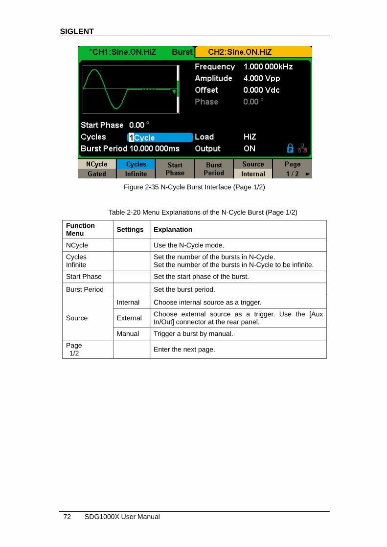
SDG1000X User Manual 73
Figure 2-36 N-Cycle Burst Interface (Page 2/2)
Table 2-21 Menu Explanations of the N-Cycle Burst (Page2/2)
Function Menu
Settings Explanation
Delay Set the delay time before the burst starts.
Trig Out Off Disable trigger out.
On Enable trigger out.
Page 2/2
Return to the previous page.
Infinite
In infinite mode, the cycle number of the waveform is set as an infinite value.
The generator outputs a continuous waveform after receiving the trigger signal.
Waveforms that support infinite mode include sine, square, ramp, pulse and
arbitrary.
Press Burst → NCycle → Infinite, and set the trigger source to ―external‖ or
―manual‖. The screen will display an infinite cycle burst, as shown in Figure
2-37.

SIGLENT
74 SDG1000X User Manual
Figure 2-37 Infinite Burst Interface
Gated
In gated mode, the generator controls the waveform output according to the
gate signal level. When the gated signal is ―true‖, the generator outputs a
continuous waveform. When the gated signal is ―false‖, the generator first
completes the output of the current period and then stops. Waveforms that
support gated burst include sine, square, ramp, pulse, noise and arbitrary.
Press Burst → Gated, to enter the following interface.
Figure 2-38 Gated Burst Interface

SIGLENT
SDG1000X User Manual 75
Table 2-22 Menu Explanations of the Gated Burst
Function Menu
Settings Explanation
Gated Use the gated mode.
Polarity Positive
Set the polarity for the gated signal. Negative
Start Phase Set the start phase of the burst.
Burst Period Set the burst Period.
Source
Internal Choose internal source as a trigger.
External Choose external source as a trigger. Use the [Aux In/Out] connector at the rear panel.
Start Phase
Define the start point in a waveform. The phase varies from 0° to 360°, and the
default setting is 0°. For an Arbitrary Waveform, 0° is the first waveform
point.
Burst Period
Burst Period is only available when the trigger source is internal. It is defined
as the time from the start of a burst to the start of the next one. Choose Burst
Period and use the numeric keyboard or arrow keys and knob to input the
desired value.
Burst Period ≥ 0.99μs + carrier period × burst number
If the current burst period set is too short, the generator will increase this
value automatically to allow outputting the specified number of cycles.
Cycles/Infinite
Set the number of waveform cycle in an N-Cycle (1 to 50,000 or Infinite).
If Infinite is chosen, then a continuous waveform will be generated once a
trigger occurs.
SIGLENT
76 SDG1000X User Manual
Delay
Set the time delay between the trigger input and the start of the N-Cycle burst.
Burst Trigger Source
The burst trigger source can be internal, external or manual. The generator
will generate a burst output when a trigger signal is received and then wait for
the next trigger source.
1. Internal Trigger
Choose Source → Internal, the generator outputs continuous burst waveform
when internal trigger is selected. Choose Trig Out as ―Up‖ or ―Down‖, the [Aux
In/Out] connector at the rear panel will output a trigger signal with specified
edge.
2. External Trigger
Choose Source → External, the generator accepts the trigger signal inputted
from the [Aux In/Out] connector at the rear panel when external trigger is
selected. A burst will be generated once the connector gets a CMOS pulse
with specified polarity. To set the CMOS pulse polarity, choose Edge to select
―Up‖ or ―Down‖.
3. Manual Trigger
Choose Source → Manual, a burst will be generated from the corresponding
channel when the Trigger softkey is pressed when manual trigger is selected.

SIGLENT
SDG1000X User Manual 77
2.12 To Store and Recall
SDG1000X can store the current instrument state and user-defined arbitrary
waveform data in internal or external memory and recall them when needed.
Press Store/Recall to enter the following interface.
Figure 2-39 Store/Recall Interface (Page 1/2)
Table 2-23 Menu Explanations of Save and Recall
Function Menu
Settings Explanation
File Type State The setting of the generator;
Data Arbitrary waveform file
Browse View the current directory.
Save Save the waveform to the specified path.
Recall Recall the waveform or setting information in the specific position of the memory.
Delete Delete the selected file.
Page 1/2
Enter the next page.
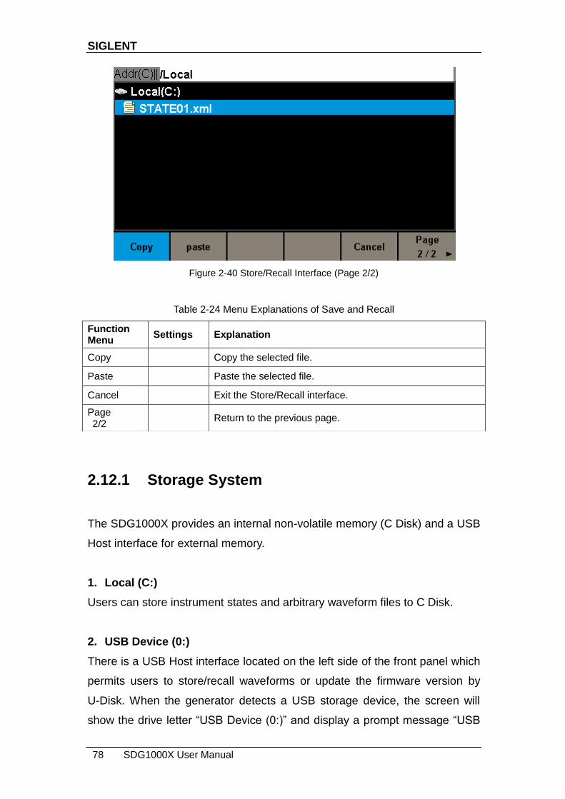
SIGLENT
78 SDG1000X User Manual
Figure 2-40 Store/Recall Interface (Page 2/2)
Table 2-24 Menu Explanations of Save and Recall
2.12.1 Storage System
The SDG1000X provides an internal non-volatile memory (C Disk) and a USB
Host interface for external memory.
1. Local (C:)
Users can store instrument states and arbitrary waveform files to C Disk.
2. USB Device (0:)
There is a USB Host interface located on the left side of the front panel which
permits users to store/recall waveforms or update the firmware version by
U-Disk. When the generator detects a USB storage device, the screen will
show the drive letter ―USB Device (0:)‖ and display a prompt message ―USB
Function Menu
Settings Explanation
Copy Copy the selected file.
Paste Paste the selected file.
Cancel Exit the Store/Recall interface.
Page 2/2
Return to the previous page.

SIGLENT
SDG1000X User Manual 79
device connected.‖, as shown in Figure 2-41. After removing the U-Disk, the
screen will display a prompt message ―USB device removed.‖ And ―USB
Device (0:)‖ in the storage menu will disappear.
Figure 2-41 Storage System
Note:
The SDG1000X can only identify files of which filenames consist of English
letters, number and underscore. If other characters are used, the name may
be displayed in the store and recall interface abnormally.
Browse
Use the knob to shift between the directories to choose Local (C:) or USB
Device (0:). Choose Browse, press the knob to open the current directory.
Use the knob to switch between folder and files under the current directory.
Choose Browse, press the knob to open the subdirectory. Choose <up>,
then choose Brower or press the knob to return to the upper level
directory.
2.12.2 File Type
Choose Store/Recall → File Type to select the desired file type. Available file
types are State File and Data File.
SIGLENT
80 SDG1000X User Manual
State File
Store the instrument state in internal or external memory in ―*.xml‖ format. The
state file stored includes waveform parameters and modulation, sweep, burst
parameters of two channels and utility parameters.
Data File
The SDG1000X can recall the data files in ―*.csv‖ or ―*.dat‖ format from the
external memory and transfer them into ―*.bin‖ format then store them in the
internal memory. When it is done, the generator will enter the arbitrary
waveform interface automatically.
In addition, users can edit arbitrary waveforms with PC software — EasyWave,
download them to the internal memory through remote interface and store
them (in ―*.bin‖ format) in the internal memory.
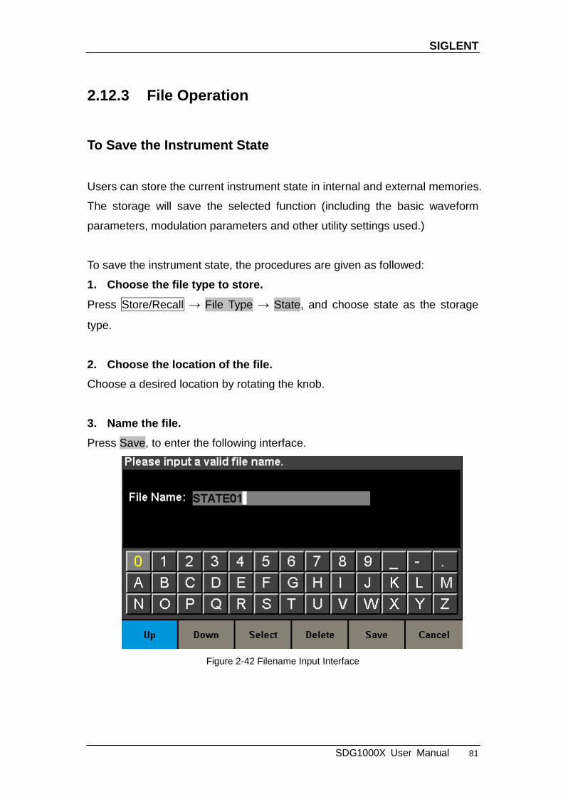
SIGLENT
SDG1000X User Manual 81
2.12.3 File Operation
To Save the Instrument State
Users can store the current instrument state in internal and external memories.
The storage will save the selected function (including the basic waveform
parameters, modulation parameters and other utility settings used.)
To save the instrument state, the procedures are given as followed:
1. Choose the file type to store.
Press Store/Recall → File Type → State, and choose state as the storage
type.
2. Choose the location of the file.
Choose a desired location by rotating the knob.
3. Name the file.
Press Save, to enter the following interface.
Figure 2-42 Filename Input Interface

SIGLENT
82 SDG1000X User Manual
Table 2-25 Menu Explanation of File Storage
Function Menu
Settings Explanation
Up Cursor upward to select.
Down Cursor downward to select.
Select Select the current character.
Delete Delete the current character.
Save Store the file with the current name.
Cancel Return to the store/Recall interface.
Select the character
Users can select the desired character from the virtual soft keyboard by using
the knob or Up and Down menus. Then choose Select to display the character
selected in the filename area.
Delete the character
Use the left and right arrow keys to move the cursor in the file name. Then
choose Delete to delete the corresponding character.
4. Save the file.
After finishing inputting filename, press Save. The generator will save the file
under the currently selected directory with the specified filename.
To Recall State File or Data File
To recall the instrument state or arbitrary waveform data, the procedures are
as follows:
1. Choose the file type.
Press Store/Recall → File Type, and choose state or data as the storage type.
2. Choose the file to be recalled.
SIGLENT
SDG1000X User Manual 83
Rotate the knob to select the file you want to recall.
3. Recall the file.
Choose Recall, press the knob, the generator will recall the selected file and
display corresponding prompt message when the file is read successfully.
To Delete File
To delete the instrument state or arbitrary waveform data, the procedures are
as follows:
1. Choose the file.
Rotate the knob to select the file you want to delete.
2. Delete the file.
Choose Delete, the generator will display prompt message ‗Delete the file?‘
Then press Accept, the generator will delete the currently selected file.
To Copy and Paste File
SDG1000X supports the internal and external storage to copy files from each
other. For example, copy an arbitrary wave file in the U-disk to the instrument,
the procedure is as follows:
1. Choose the file type.
Press Store/Recall → File Type, and choose ―Data‖ as the storage type.
2. Choose the file to be copied.
Rotate the knob to select USB Device (0:) and press the knob to open its
directory. Then rotate the knob to select the file you want to copy and press
Page 1/2 → Copy.

SIGLENT
84 SDG1000X User Manual
3. Paste the file.
Rotate the knob to select Local (C:) and press the knob to open its directory.
Then press Paste.
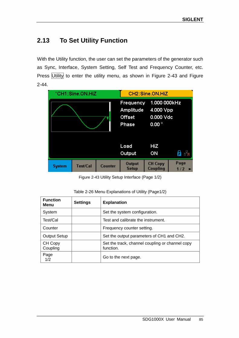
SIGLENT
SDG1000X User Manual 85
2.13 To Set Utility Function
With the Utility function, the user can set the parameters of the generator such
as Sync, Interface, System Setting, Self Test and Frequency Counter, etc.
Press Utility to enter the utility menu, as shown in Figure 2-43 and Figure
2-44.
Figure 2-43 Utility Setup Interface (Page 1/2)
Table 2-26 Menu Explanations of Utility (Page1/2)
Function Menu
Settings Explanation
System Set the system configuration.
Test/Cal Test and calibrate the instrument.
Counter Frequency counter setting.
Output Setup Set the output parameters of CH1 and CH2.
CH Copy Coupling
Set the track, channel coupling or channel copy function.
Page 1/2
Go to the next page.

SIGLENT
86 SDG1000X User Manual
Figure 2-44 Utility Setup Interface (Page 2/2)
Table 2-27 Menu Explanations of Utility (Page2/2)
Function Menu
Settings Explanation
Interface Set the parameters of remote interfaces.
Sync Set the sync output.
CLKSource Internal
Choose the system clock source. External
Mode Choose Phase-locked or independent mode.
OverVoltage Protection
Turn on/off the overvoltage protection function.
Page 2/2
Return to the previous page.

SIGLENT
SDG1000X User Manual 87
2.13.1 System Settings
Press Utility → System, to enter the following interface.
Figure 2-45 System Setup Interface (Page 1/2)
Table 2-28 Menu Explanations of System Setup (Page 1/2)
Function Menu
Settings Explanation
Number format
Set the number format.
Language English
Set the language. Chinese
PowerOn Default All the settings return to default when power on;
Last All the settings return to the setting of last power on.
Set to Default
Set all the settings to default.
Beeper On Open the beeper.
Off Close the beeper.
Page 1/2
Enter the next page.

SIGLENT
88 SDG1000X User Manual
Figure 2-46 System Setup Interface (Page 2/2)
Table 2-29 Menu Explanations of System Setup (Page 2/2)
Function Menu
Settings Explanation
ScrnSvr
1min
Enable or disable the screen saver.
5min
15min
30min
1hour
2hour
5hour
Off Disable the screen saver.
System Info View the system information
Firmware Update
Update the firmware by the U-disk.
Help View the help information.
Accept Save the current settings and return to the Utility menu.
Page 2/2
Return to the previous page.
1. Number Format
Press Utility → System → Number Format, to enter the following interface.

SIGLENT
SDG1000X User Manual 89
Figure 2-47 Set the Number Format
Table 2-30 Menu Explanations of Setting the Number Format
Function Menu
Settings Explanation
Point . Use dot to represent decimal point;
, Use comma to represent decimal point.
Separator
On Enable the Separator;
Off Close the Separator;
Space Use Space as the separator.
Accept Save the current settings and return to the System menu.
According to the different choices of the decimal point and the separator, the
format can have various forms.
2. Language Setup
The generator offers two languages (English and Simplified Chinese). Press
Utility → System → Language, to select the desired language. This setting is
stored in non-volatile memory and will not be influenced by the Set To Default
operation.

SIGLENT
90 SDG1000X User Manual
English Interface
Figure 2-48 English Interface
Chinese Interface
Figure 2-49 Chinese Interface
3. Power On
Choose the SDG1000X‘s setting when the generator is powered on. Two
choices are available: the default setting and the last settings set when the unit
was last powered down. Once selected, the setting will be applied when the
instrument is powered on. This setting is stored in non-volatile memory and
will not be influenced by the Set To Default operation.

SIGLENT
SDG1000X User Manual 91
Last: includes all system parameters and states, except channel output
state.
Default: denotes the factory defaults except certain parameters (such as
Language).
4. Set to Default
Press Utility → System → Set To Default, to set the system to the default
setting. The default settings of the system are as followed:
Table 2-31 Factory Default Setting
Output Default
Function Sine Wave
Frequency 1kHz
Amplitude/Offset 4Vpp/0Vdc
Phase 0°
Load High Z
Modulation Default
Carrier 1kHz Sine Wave
Modulating 100Hz Sine Wave
AM Depth 100%
FM Deviation 100Hz
ASK Key Frequency 100Hz
FSK Key Frequency 100Hz
FSK Hop Frequency 1MHz
PSK Key Frequency 100Hz
PM Phase Deviation 100°
PWM Width Dev 190μs
Sweep Default
Start/Stop Frequency 500Hz/1.5kHz
Sweep Time 1s
Trig Out Off
Mode Linear

SIGLENT
92 SDG1000X User Manual
Direction ↑
Burst Default
Burst Period 10ms
Start Phase 0°
Cycles 1Cycle
Trig Out Off
Delay 521ns
Trigger Default
Source Internal
5. Beeper
Enable or disable the beeper. Press Utility →System → Beeper to select ―On‖
or ―Off‖ and the default is ―On‖.
6. Screen Saver
Enable or disable screen saver. Press Utility → System → Page 1/2 →
ScrnSvr to select ―On‖ or ―Off‖ and the default is ―Off‖. Screen saver will be on
if no action is taken within the time that you have selected. Press any key to
resume.
7. System Info
Select the System Info option of the utility menu to view the generator‘s
system information, including startup times, software version, hardware
version, model and serial number.

SIGLENT
SDG1000X User Manual 93
Figure 2-50 System Information Interface
8. Update
The software version and configuration file of the generator can be updated
directly via U-disk. Follow the steps below:
1. Insert U-disk with firmware update file (*.ADS) and configuration file
(*.CFG) to USB host interface on the front panel of the generator.
2. Press Utility → Page 1/2 → Firmware Update. Or press Store/Recall
directly.
3. Select the firmware file (*.ADS) and choose Recall to update the system
software.
4. After the updating is finished, the generator will restart automatically.
5. Press Utility → Page 1/2 → Firmware Update. Or press Store/Recall
directly.
6. Select the configuration file (*.CFG) and choose Recall to update the
configuration file.
7. After the updating is finished, the generator will restart automatically.
Note:
1. Don‘t cut off the power during the generator is being updated!
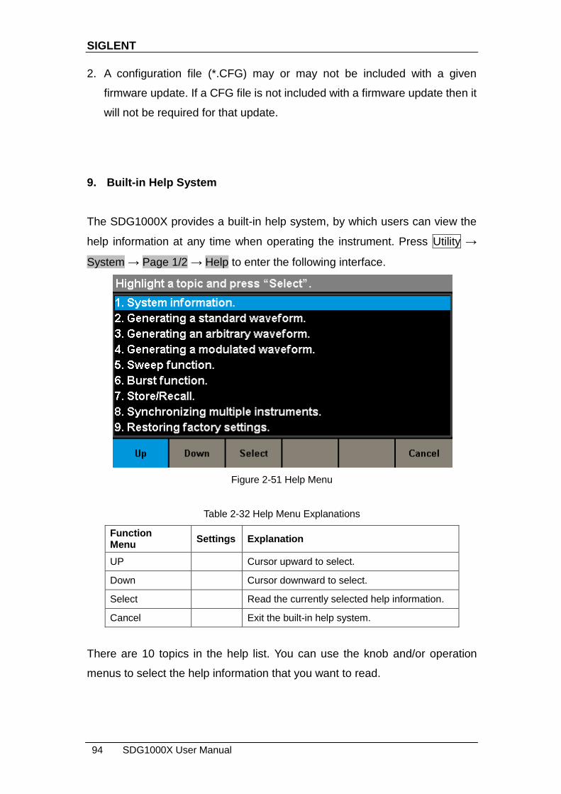
SIGLENT
94 SDG1000X User Manual
2. A configuration file (*.CFG) may or may not be included with a given
firmware update. If a CFG file is not included with a firmware update then it
will not be required for that update.
9. Built-in Help System
The SDG1000X provides a built-in help system, by which users can view the
help information at any time when operating the instrument. Press Utility →
System → Page 1/2 → Help to enter the following interface.
Figure 2-51 Help Menu
Table 2-32 Help Menu Explanations
Function Menu
Settings Explanation
UP Cursor upward to select.
Down Cursor downward to select.
Select Read the currently selected help information.
Cancel Exit the built-in help system.
There are 10 topics in the help list. You can use the knob and/or operation
menus to select the help information that you want to read.

SIGLENT
SDG1000X User Manual 95
2.13.2 Test/Cal
Choose Utility → Test/Cal, to enter the following interface.
Figure 2-52 Test/Cal function Menu
Table 2-33 Menu Explanations of Test/Cal Setting
Function Menu
Settings Explain
SelfTest Perform a system self-test.
Cancel Return to the Utility menu.
Self Test
Press Utility → Test/Cal → SelfTest, to enter the following menu.

SIGLENT
96 SDG1000X User Manual
Figure 2-53 Self Test Interface
Table 2-34 Menu Explanations of Self Test
Function Menu
Settings Explain
ScrTest Run screen test program.
KeyTest Run keyboard test program.
LEDTest Run key indicator lights test program.
BoardTest Run hardware circuit self-test program.
Cancel Return to the Test/Cal menu.
1. ScrTest
Select ScrTest to enter the screen test interface. The prompt message ‗Please
press ‗7‘ key to continue, press ‗8‘ key to exit.‘ is displayed. Press the ‗7‘ key
for test and observe if there is any serious color deviation, bad pixel or display
error.

SIGLENT
SDG1000X User Manual 97
Figure 2-54 Screen Test Interface
2. Key Test
Select KeyTest to enter the keyboard test interface, the on-screen white
rectangle shapes represent the front panel keys. The circle between two
arrows represents the knob. Test all keys and knob and also verify that all the
backlight keys illuminate correctly.
Figure 2-55 Key Test Interface
The corresponding area of tested keys or knob would display in blue color.
The top of the screen displays ‗Please press ‗8‘ key three times to exit.‘
3. LED Test
Select LEDTest to enter the LED test interface, the on-screen white rectangle
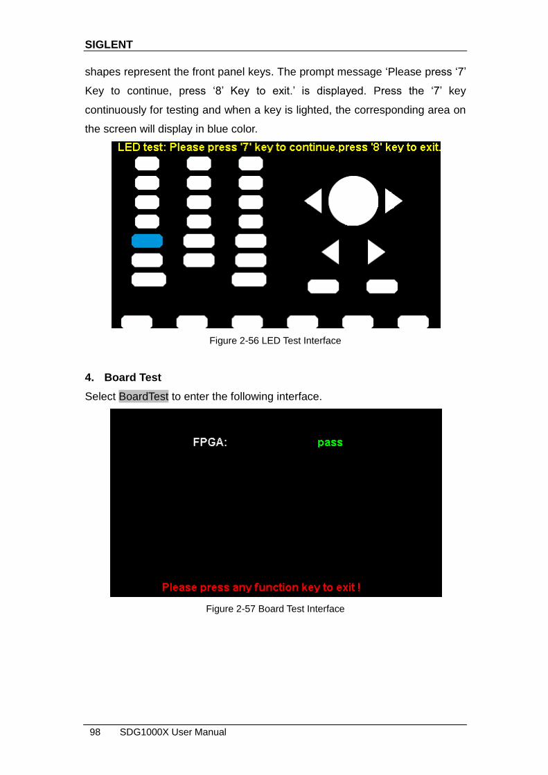
SIGLENT
98 SDG1000X User Manual
shapes represent the front panel keys. The prompt message ‗Please press ‗7‘
Key to continue, press ‗8‘ Key to exit.‘ is displayed. Press the ‗7‘ key
continuously for testing and when a key is lighted, the corresponding area on
the screen will display in blue color.
Figure 2-56 LED Test Interface
4. Board Test
Select BoardTest to enter the following interface.
Figure 2-57 Board Test Interface

SIGLENT
SDG1000X User Manual 99
2.13.3 Frequency Counter
The SDG1000X provides a frequency counter which could measure
frequencies between 100mHz to 200MHz. The dual channels can still output
normally when the counter is enabled. Press Utility → Counter, to enter the
following interface.
Figure 2-58 Frequency Counter Interface
Table 2-35 Menu Explanations of Frequency Counter
Function Menu
Settings Explanation
State Off Open the counter.
On Close the counter.
Frequency Measured frequency.
Period Measured period.
PWidth Measured positive width.
NWidth Measured negative width.
RefFreq Set the reference frequency. System will calculate the deviation between the measured frequency and the reference frequency automatically.
TrigLev Set the trigger level voltage.
Duty Measured duty.
Setup Set the counter configuration.
Clear Clear the statistic data.

SIGLENT
100 SDG1000X User Manual
Figure 2-59 Counter Setup Interface
Table 2-36 Menu Explanations of Setup
Function Menu
Settings Explanation
Mode DC Set the coupling mode to DC
AC Set the coupling mode to AC
HFR On Open the high frequency rejection filter.
Off Close the high frequency rejection filter.
Default Set the frequency counter settings to default.
Accept Save the current settings and return to the previous menu.
1. To Select the Parameters to be measured
The frequency counter on the SDG1000X can measure parameters including
frequency, period, duty, positive pulse width and negative pulse width.
2. Reference Frequency
System will calculate the deviation between the measured frequency and the
reference frequency automatically.
3. Trigger Level
Sets the trigger level of the measurement system. The system triggers and
obtains the measurement readings when the input signal reaches the
SIGLENT
SDG1000X User Manual 101
specified trigger level. The default is 0V and the available range is from -3V to
1.5V. Choose TrigLev and use the numeric keyboard to input the desired value
and select the unit (V or mV) from the pop-up menu. Or use the knob and
arrow keys to change the parameter value.
4. Coupling Mode
Sets the coupling model of the input signal to ―AC‖ or ―DC‖. The default is
―AC‖.
5. HFR
High Frequency Rejection can be used to filter out the high-frequency
components of a measured signal and improve the measurement accuracy in
low-frequency signal measurement. Press HFR to enable or disable this
function. The default is ―Off‖.
Enable High Frequency Rejection when low-frequency signal with lower
than a 250kHz frequency is measured to filter out the high-frequency
noise interference.
Disable High Frequency Rejection when a signal with a frequency higher
than 250 KHz is measured. The maximum frequency that can be counted
is 200 MHz.
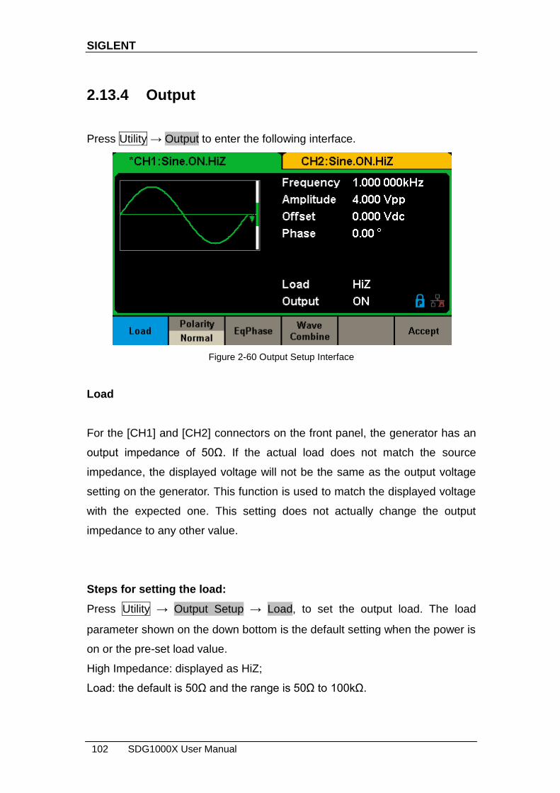
SIGLENT
102 SDG1000X User Manual
2.13.4 Output
Press Utility → Output to enter the following interface.
Figure 2-60 Output Setup Interface
Load
For the [CH1] and [CH2] connectors on the front panel, the generator has an
output impedance of 50Ω. If the actual load does not match the source
impedance, the displayed voltage will not be the same as the output voltage
setting on the generator. This function is used to match the displayed voltage
with the expected one. This setting does not actually change the output
impedance to any other value.
Steps for setting the load:
Press Utility → Output Setup → Load, to set the output load. The load
parameter shown on the down bottom is the default setting when the power is
on or the pre-set load value.
High Impedance: displayed as HiZ;
Load: the default is 50Ω and the range is 50Ω to 100kΩ.

SIGLENT
SDG1000X User Manual 103
Note:
Continue pressing the corresponding output key for two second to switch
between High Impedance and 50Ω.
Polarity
Press Utility → Output Setup → Polarity to set the output signal as normal or
inverted. The waveform‘s inversion is relative to the offset voltage, as shown in
the following figure.
Note:
The Sync signal related to the waveform is not inverted when the waveform is
inverted.
EqPhase
Press Utility → Output Setup → EqPhase to align the phases of CH1 and CH2.
Choosing the menu will re-configure two channels and enable the generator to
output with specified frequency and start phase. For two signals whose
frequencies are the same or a multiple thereof, this operation will align their
phases.
Waveforms Combining
The CH1 output port of the SDG1000X outputs the waveform of CH1 in the
general mode, while the waveform of CH1+CH2 can be output in the
combined mode. Similarly, the CH2 output port of SDG1000X outputs the

SIGLENT
104 SDG1000X User Manual
waveform of CH2 in the general mode while the waveform of CH1+CH2 can
be output in the combined mode.
Press Utility → Output Setup → Wave Combine to enter the waveforms
combining interface, as shown in the following figure.
Figure 2-61 Waveforms Combining Interface
Table 2-37 Menu Explanations of Wave Combine
Function Menu
Settings Explanation
CH1 Switch CH1 Output the waveform of CH1.
CH1+CH2 Output the waveform of CH1+CH2.
CH2 Switch CH2 Output the waveform of CH2.
CH1+CH2 Output the waveform of CH1+CH2.
Return Save the current operation and exit the current interface.
Note:
1. The square waveform function of the SDG1000X can only serve as an
independent channel. Combining with a Square waveform is not possible.
2. When the waveforms combining function is enabled, the load of two
channels will be set to the same automatically, default using the load value
of the currently operated channel.
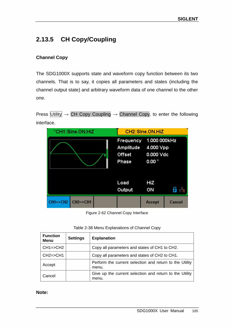
SIGLENT
SDG1000X User Manual 105
2.13.5 CH Copy/Coupling
Channel Copy
The SDG1000X supports state and waveform copy function between its two
channels. That is to say, it copies all parameters and states (including the
channel output state) and arbitrary waveform data of one channel to the other
one.
Press Utility → CH Copy Coupling → Channel Copy, to enter the following
interface.
Figure 2-62 Channel Copy Interface
Table 2-38 Menu Explanations of Channel Copy
Function Menu
Settings Explanation
CH1=>CH2 Copy all parameters and states of CH1 to CH2.
CH2=>CH1 Copy all parameters and states of CH2 to CH1.
Accept Perform the current selection and return to the Utility menu.
Cancel Give up the current selection and return to the Utility menu.
Note:
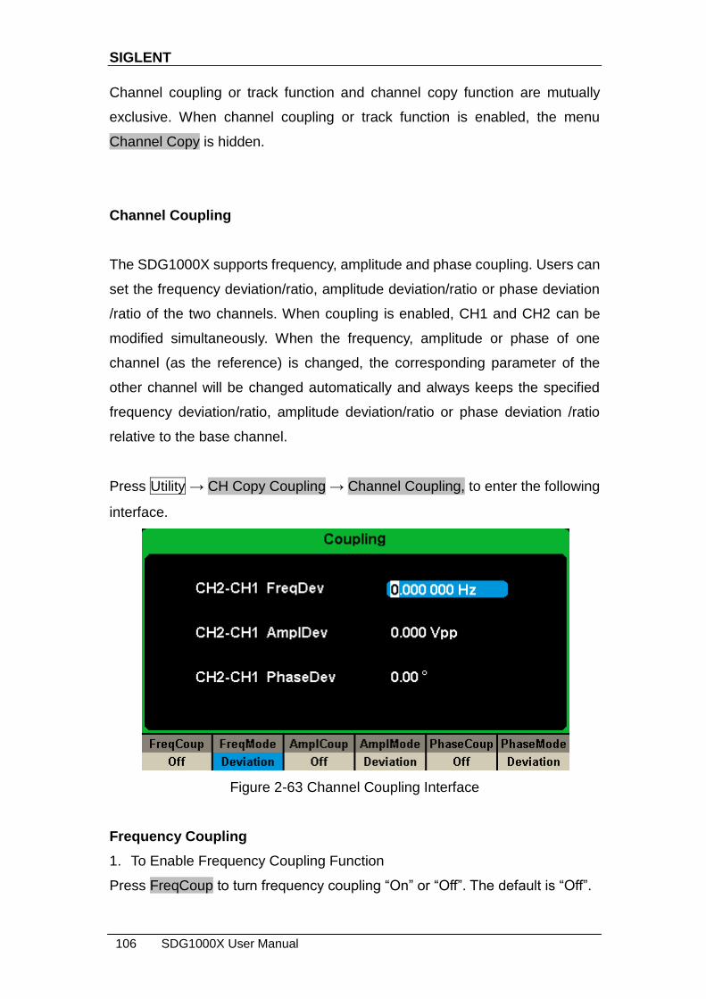
SIGLENT
106 SDG1000X User Manual
Channel coupling or track function and channel copy function are mutually
exclusive. When channel coupling or track function is enabled, the menu
Channel Copy is hidden.
Channel Coupling
The SDG1000X supports frequency, amplitude and phase coupling. Users can
set the frequency deviation/ratio, amplitude deviation/ratio or phase deviation
/ratio of the two channels. When coupling is enabled, CH1 and CH2 can be
modified simultaneously. When the frequency, amplitude or phase of one
channel (as the reference) is changed, the corresponding parameter of the
other channel will be changed automatically and always keeps the specified
frequency deviation/ratio, amplitude deviation/ratio or phase deviation /ratio
relative to the base channel.
Press Utility → CH Copy Coupling → Channel Coupling, to enter the following
interface.
Figure 2-63 Channel Coupling Interface
Frequency Coupling
1. To Enable Frequency Coupling Function
Press FreqCoup to turn frequency coupling ―On‖ or ―Off‖. The default is ―Off‖.

SIGLENT
SDG1000X User Manual 107
2. To Select Frequency Coupling Mode
Press FreqMode to choose ―Deviation‖ or ―Ratio‖, and then use the numeric
keyboard or knob and arrow keys to input the desired value.
Deviation: the frequency deviation between CH1 and CH2. The resulting
signal is represented by: FreqCH2-FreqCH1=FreqDev.
Ratio: the frequency ratio of CH1 and CH2. The resulting signal is
represented by: FreqCH2/FreqCH1=FreqRatio.
Amplitude Coupling
1. To Enable Amplitude Coupling Function
Press AmplCoup to turn amplitude coupling ―On‖ or ―Off‖. The default is ―Off‖.
2. To Select Amplitude Coupling Mode
Press AmplMode to choose ―Deviation‖ or ―Ratio‖, and then use the numeric
keyboard or knob and arrow keys to input the desired value.
Deviation: the amplitude deviation between CH1 and CH2. The resulting
signal is represented by: AmplCH2-AmplCH1=AmplDev.
Ratio: the amplitude ratio of CH1 and CH2. The resulting signal is
represented by: AmplCH2/AmplCH1=AmplRatio.
Phase Coupling
1. To Enable Phase Coupling Function
Press PhaseCoup to turn phase coupling ―On‖ or ―Off‖. The default is ―Off‖.
2. To Select Phase Coupling Mode
Press PhaseMode to choose ―Deviation‖ or ―Ratio‖, and then use the numeric
keyboard or knob and arrow keys to input the desired value.
Deviation: the phase deviation between CH1 and CH2. The resulting
signal is represented by: PhaseCH2-PhaseCH1=PhaseDev.
Ratio: the phase ratio of CH1 and CH2. The resulting signal is represented
by: PhaseCH2/PhaseCH1=PhaseRatio.
Key Points:
1. Channel coupling is only available when both the waveforms of the two
channels are basic waveforms including Sine, Square, Ramp and Arbitrary.
2. When the Phase Coupling function is enabled, if the phase of one channel

SIGLENT
108 SDG1000X User Manual
is changed, the phase of the other channel will be changed accordingly. At
this point, aligning phase between the two channels can be achieved
without executing the Eqphase operation.
3. Channel coupling and channel function are mutually exclusive. When
channel coupling is enabled, the menu Channel Copy is hidden.
Channel Track
When the track function is enabled, by changing the parameters or states of
CH1, the corresponding parameters or states of CH2 will be adjusted to the
same values or states automatically. At this point, the dual channels can
output the same signal.
Choose Utility → CH Copy Coupling → Track to enable or disable the track
function. When the track function is enabled, channel copy and coupling
functions are disabled; the user interface is switched to CH1 and cannot be
switched to CH2, as shown in the following figure.
Figure 2-64 Track Interface
Press PhaseDev to enter the following interface. Then use the numeric
keyboard or knob and arrow keys to input the desired value for the phase
deviation between CH1 and CH2. The resulting signal is represented by:
PhaseCH2-PhaseCH1=PhaseDev.

SIGLENT
SDG1000X User Manual 109
Figure 2-65 Phase Deviation Interface
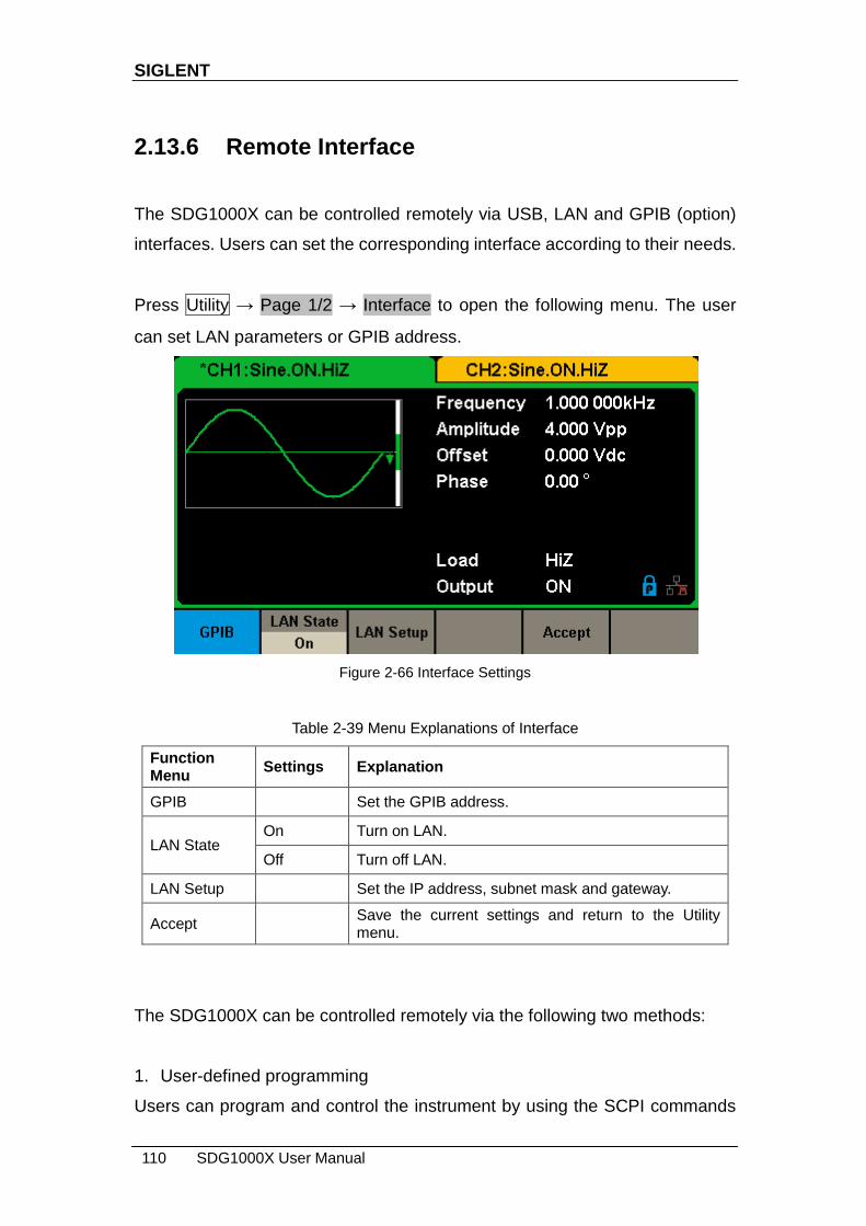
SIGLENT
110 SDG1000X User Manual
2.13.6 Remote Interface
The SDG1000X can be controlled remotely via USB, LAN and GPIB (option)
interfaces. Users can set the corresponding interface according to their needs.
Press Utility → Page 1/2 → Interface to open the following menu. The user
can set LAN parameters or GPIB address.
Figure 2-66 Interface Settings
Table 2-39 Menu Explanations of Interface
Function Menu
Settings Explanation
GPIB Set the GPIB address.
LAN State On Turn on LAN.
Off Turn off LAN.
LAN Setup Set the IP address, subnet mask and gateway.
Accept Save the current settings and return to the Utility menu.
The SDG1000X can be controlled remotely via the following two methods:
1. User-defined programming
Users can program and control the instrument by using the SCPI commands
SIGLENT
SDG1000X User Manual 111
(Standard Commands for Programmable Instruments). For more information
about the commands and programming, please refer to ―Remote Control
Manual‖.
2. PC software
Users can use the PC software Measurement & Automation Explorer of NI
(National Instruments Corporation) to send commands to control the
instrument remotely.
Remote Control via USB
The SDG1000X can communicate with a PC through the USBTMC protocol.
You are suggested to do as the following steps.
1. Connect the device.
Connect the USB Device interface at the rear panel of SDG1000X with the PC
via a USB cable.
2. Install the USB driver.
NI Visa is recommended.
3. Communicate with a remote PC
Open Measurement & Automation Explorer of NI and choose the
corresponding resource name. Then click ―Open VISA Test Panel‖ to turn on
the remote command control panel through which you can send commands
and read data.
Remote Control via GPIB
Each device connected to GPIB interface must have a unique address. The
default value is 18 and values range from 1 to 30. The selected address is
stored in non-volatile memory.

SIGLENT
112 SDG1000X User Manual
1. Connect the device.
Connect the generator to the computer using a USB to GPIB adapter (option).
Note:
Please make sure that the PC has a GPIB interface card installed.
Connect the USB terminal of the USB to GPIB adapter to the USB Host
interface at the front panel of the generator and the GPIB terminal to the GPIB
card terminal of the PC.
2. Install the driver of GPIB card.
Please install the driver for the GPIB card which has been connected to your
PC.
3. Set the GPIB address.
Choose Utility → Page 1/2 → Interface → GPIB to enter the following
interface. Users can use the knob, arrow keys or numeric keyboard to change
the value and press Accept to save the current setting.
Figure 2-67 GPIB Setting Interface
4. Communicate with PC remotely
Open Measurement & Automation Explorer of NI. After adding the GPIB
device successfully, choose the corresponding resource name. Then click
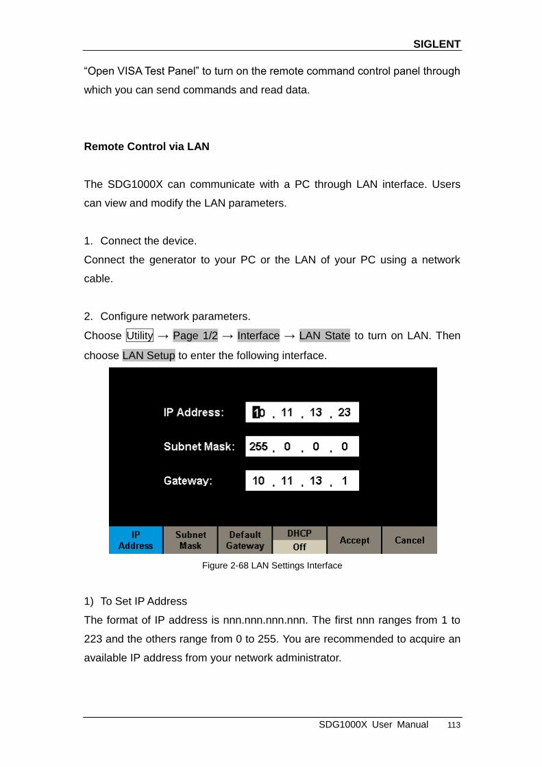
SIGLENT
SDG1000X User Manual 113
―Open VISA Test Panel‖ to turn on the remote command control panel through
which you can send commands and read data.
Remote Control via LAN
The SDG1000X can communicate with a PC through LAN interface. Users
can view and modify the LAN parameters.
1. Connect the device.
Connect the generator to your PC or the LAN of your PC using a network
cable.
2. Configure network parameters.
Choose Utility → Page 1/2 → Interface → LAN State to turn on LAN. Then
choose LAN Setup to enter the following interface.
Figure 2-68 LAN Settings Interface
1) To Set IP Address
The format of IP address is nnn.nnn.nnn.nnn. The first nnn ranges from 1 to
223 and the others range from 0 to 255. You are recommended to acquire an
available IP address from your network administrator.
SIGLENT
114 SDG1000X User Manual
Press IP Address and use the arrow keys and numeric keyboard or knob to
enter your desired IP address. The setting is stored in non-volatile memory
and will be loaded automatically when the generator is powered on at the next
time.
2) To Set Subnet Mask
The format of subnet mask is nnn.nnn.nnn.nnn and each nnn ranges from 0 to
255. You are recommended to acquire an available subnet mask from your
network administrator.
Press Subnet Mask and use the arrow keys and numeric keyboard or knob to
enter your desired subnet mask. The setting is stored in non-volatile memory
and will be loaded automatically when the generator is powered on at the next
time.
3) To Set Gateway
The format of gateway is nnn.nnn.nnn.nnn and each nnn ranges from 0 to 255.
It is recommended to acquire an available gateway from your network
administrator.
Press Gateway and use the arrow keys and numeric keyboard or knob to
enter your desired gateway. The setting is stored in non-volatile memory and
will be loaded automatically when the generator is powered on at the next
time.
Note:
If the generator is connected to the PC directly, set the IP addresses,
subnet masks and gateways for both of the PC and generator. The subnet
masks and gateways of PC and generator must be the same and the IP
addresses of them must be within the same network segment.
If the generator is connected to the LAN of your PC, please contact with
your network administrator to get an available IP address. For details,
refer to the TCP/IP protocol.
SIGLENT
SDG1000X User Manual 115
4) DHCP Configuration Mode
In DHCP mode, the DHCP server in the current network assigns LAN
parameters, e.g. IP address, for the generator. Press DHCP to select ―On‖ or
―Off‖ to turn DHCP mode on or off. The default is ―Off‖.
3. Communicate with PC remotely
Open Measurement & Automation Explorer of NI. After adding the LAN device
(VISA TCP/IP Resource…) successfully, choose the corresponding resource
name. Then click ―Open VISA Test Panel‖ to turn on the remote command
control panel through which you can send commands and read data.
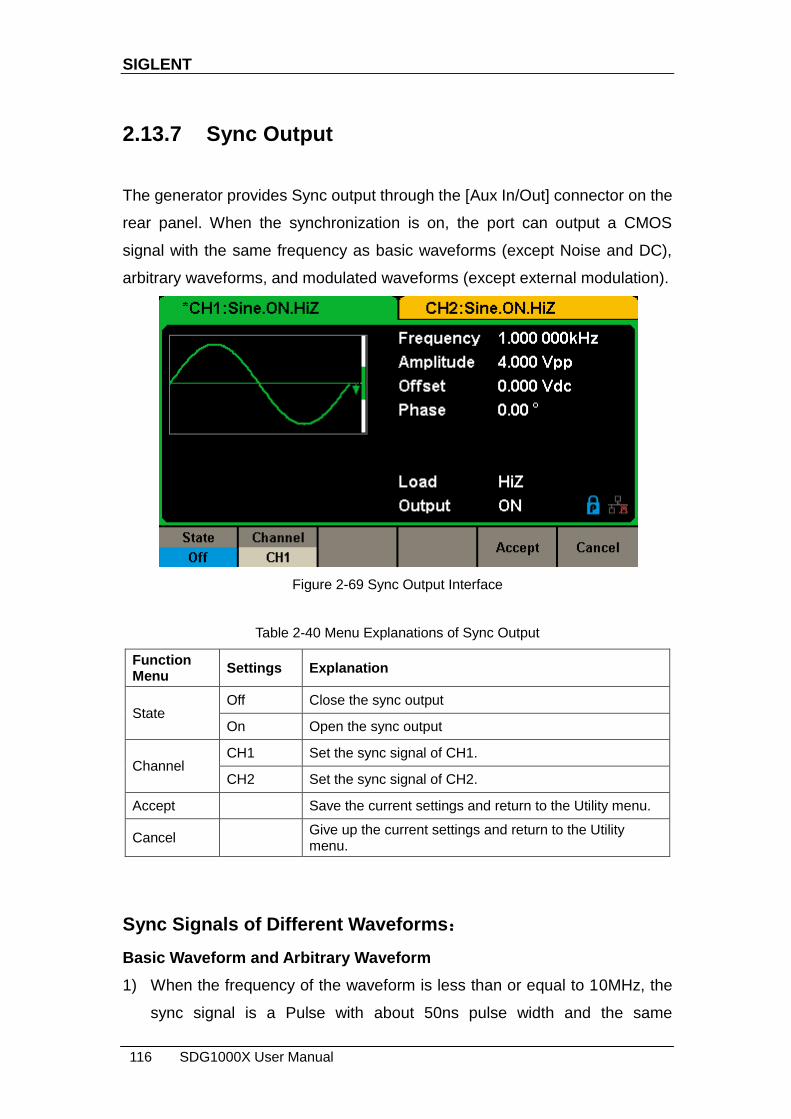
SIGLENT
116 SDG1000X User Manual
2.13.7 Sync Output
The generator provides Sync output through the [Aux In/Out] connector on the
rear panel. When the synchronization is on, the port can output a CMOS
signal with the same frequency as basic waveforms (except Noise and DC),
arbitrary waveforms, and modulated waveforms (except external modulation).
Figure 2-69 Sync Output Interface
Table 2-40 Menu Explanations of Sync Output
Function Menu
Settings Explanation
State Off Close the sync output
On Open the sync output
Channel CH1 Set the sync signal of CH1.
CH2 Set the sync signal of CH2.
Accept Save the current settings and return to the Utility menu.
Cancel Give up the current settings and return to the Utility menu.
Sync Signals of Different Waveforms:
Basic Waveform and Arbitrary Waveform
1) When the frequency of the waveform is less than or equal to 10MHz, the
sync signal is a Pulse with about 50ns pulse width and the same

SIGLENT
SDG1000X User Manual 117
frequency as the waveform.
2) When the frequency of the waveform is greater than 10MHz, there is no
sync signal output.
3) Noise and DC: there is no sync signal output.
Modulated Waveform
1) When internal modulation is selected, the sync signal is a Pulse with about
50ns pulse width.
For AM, FM, PM and PWM, the frequency of the sync signal is the
modulating frequency.
For ASK, FSK and PSK, the frequency of the sync signal is the key
frequency.
2) When external modulation is selected, there is no sync signal output, for
the [Aux In/Out] connector on the rear panel is used to input external
modulating signal.
Sweep and Burst Waveform
When Sweep or Burst function is turned on, there is no sync signal output and
the Sync menu is hidden.

SIGLENT
118 SDG1000X User Manual
2.13.8 Clock Source
The SDG1000X provides an internal 10MHz clock source. It also can accept
external clock source form the [10 MHz In/Out] connector at the rear panel. It
can also output the clock source from the [10 MHz In/Out] connector for other
devices.
Press Utility → Page 1/2 → CLKSource to select ―Internal‖ or ―External‖. If
―External‖ is selected, the instrument will detect whether a valid external clock
signal is input from the [10MHz In/Out] connector at the rear panel. If not, the
prompt message ―No external clock source!‖ would be displayed and the clock
source would be switched to ―Internal‖.
Sync methods for two or more instruments:
Synchronization between two instruments
Connect the [10MHz In/Out] connector of generator A (using internal clock) to
the [10MHz In/Out] connector of generator B (using external clock) and set the
output frequencies of A and B as a same value to achieve synchronization.
Synchronization among multiple instruments
Divide the 10MHz clock source of a generator (using internal clock) into
multiple channels, and then connect them to the [10MHz In/Out] connectors of
other generators (using External clock), and finally set the output frequencies
of all the generators as a same value to achieve synchronization.

SIGLENT
SDG1000X User Manual 119
2.13.9 Mode
Press Utility → Page 1/2 → Mode to enter the mode setup Interface, as shown
in Figure 2-70 Mode Setup Interface.
Figure 2-70 Mode Setup Interface
Phase-locked Mode
When changing the frequency, the DDSs of both channels reset, and the
phase deviation between CH1 and CH2 is maintained.
Figure 2-71 Phase-locked Mode
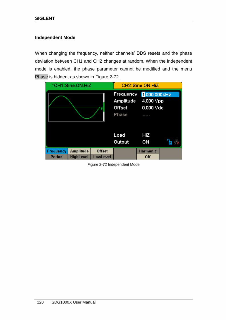
SIGLENT
120 SDG1000X User Manual
Independent Mode
When changing the frequency, neither channels‘ DDS resets and the phase
deviation between CH1 and CH2 changes at random. When the independent
mode is enabled, the phase parameter cannot be modified and the menu
Phase is hidden, as shown in Figure 2-72.
Figure 2-72 Independent Mode
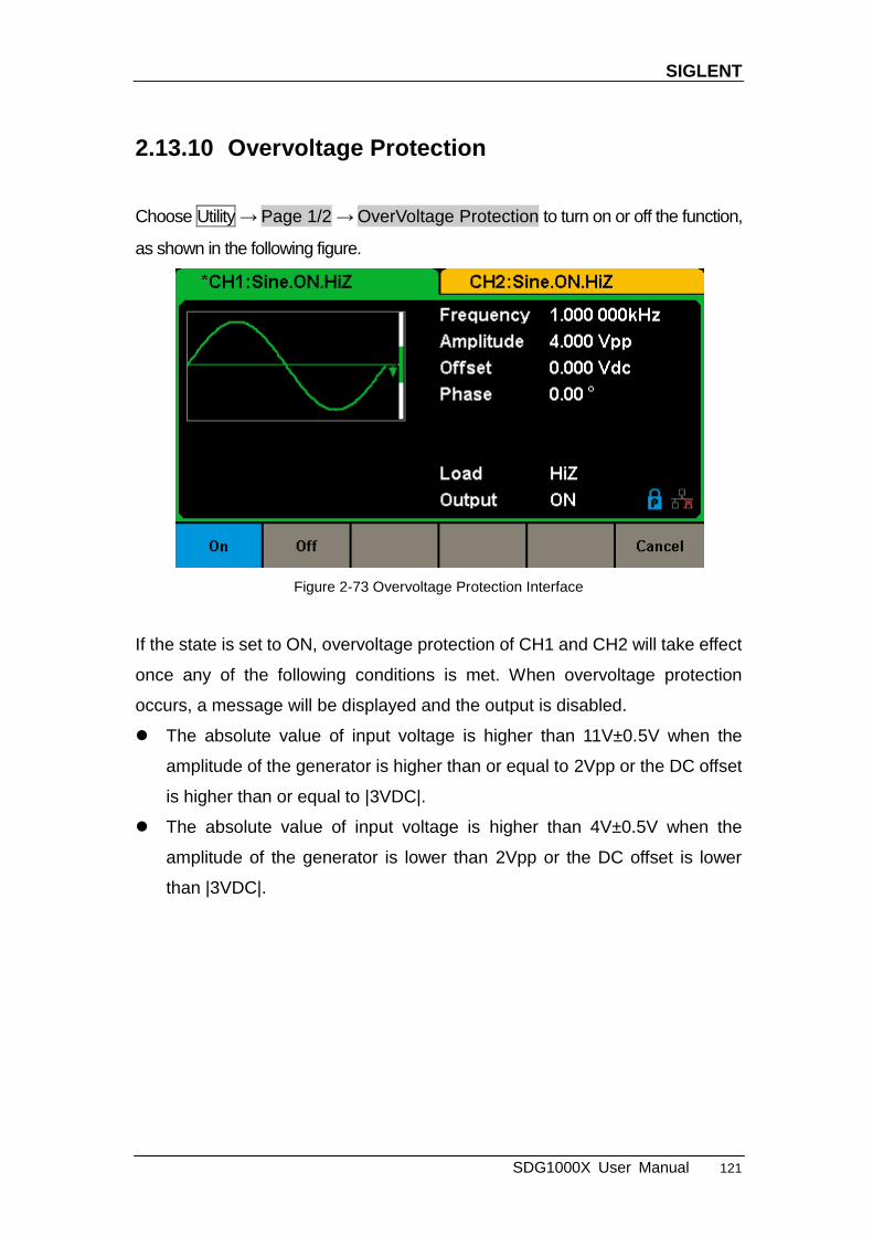
SIGLENT
SDG1000X User Manual 121
2.13.10 Overvoltage Protection
Choose Utility → Page 1/2 → OverVoltage Protection to turn on or off the function,
as shown in the following figure.
Figure 2-73 Overvoltage Protection Interface
If the state is set to ON, overvoltage protection of CH1 and CH2 will take effect
once any of the following conditions is met. When overvoltage protection
occurs, a message will be displayed and the output is disabled.
The absolute value of input voltage is higher than 11V±0.5V when the
amplitude of the generator is higher than or equal to 2Vpp or the DC offset
is higher than or equal to |3VDC|.
The absolute value of input voltage is higher than 4V±0.5V when the
amplitude of the generator is lower than 2Vpp or the DC offset is lower
than |3VDC|.
SIGLENT
122 SDG1000X User Manual
3 Examples
To help the user master how to use the SDG1000X more efficiently, we
provide some examples in detail. All the examples below use the default
setting of the instrument except in special cases.
This chapter includes the following topics:
Example 1: Generate a Sine Waveform
Example 2: Generate a Square Waveform
Example 3: Generate a Ramp Waveform
Example 4: Generate a Pulse Waveform
Example 5: Generate a Noise
Example 6: Generate a DC Waveform
Example 7: Generate a Linear Sweep Waveform
Example 8: Generate a Burst Waveform
Example 9: Generate an AM Modulation Waveform
Example 10: Generate a FM Modulation Waveform
Example 11: Generate a PM Modulation Waveform
Example 12: Generate a FSK Modulation Waveform
Example 13: Generate an ASK Modulation Waveform
Example 14: Generate a PSK Modulation Waveform
Example 15: Generate a PWM Modulation Waveform
Example 16: Generate a DSB-AM Modulation Waveform

SIGLENT
SDG1000X User Manual 123
3.1 Example 1: Generate a Sine Waveform
Generate a sine waveform with 1MHz frequency, 5Vpp amplitude and 1Vdc
offset.
Steps:
Set the frequency.
1. Press Waveforms → Sine →Frequency/Period and choose Frequency
which will display in blue color.
2. Input ‗1‘ from the keyboard and choose the unit ‗MHz‘. The frequency is
set to 1MHz.
Set the Amplitude.
1. Press Amplitude/HighLevel to choose Amplitude which will display in blue
color.
2. Input ‗5‘ from the keyboard and choose the unit ‗Vpp‘. The amplitude is set
to 5Vpp.
Set the Offset.
1. Press Offset/LowLevel to choose Offset which will display in blue color.
2. Input ‗1‘ from the keyboard and choose the unit ‗Vdc‘. The offset is set to
1Vdc.
When the frequency, amplitude and offset are set, the waveform generated is
shown in Figure 3-1.
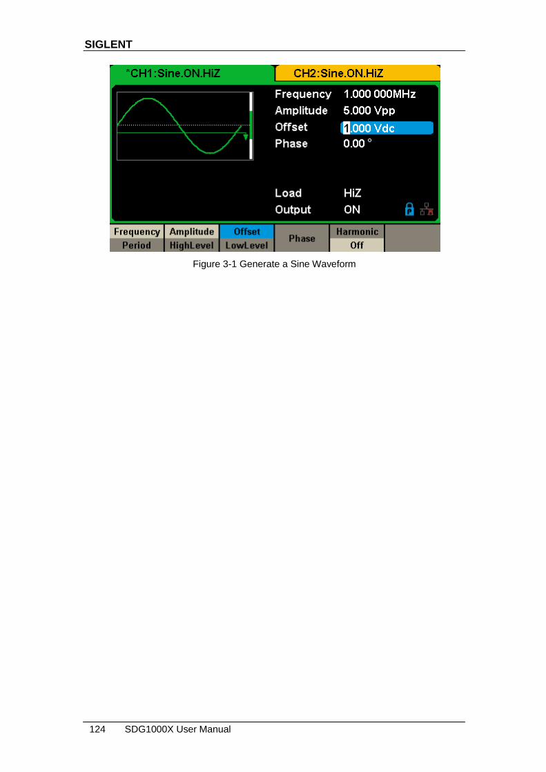
SIGLENT
124 SDG1000X User Manual
Figure 3-1 Generate a Sine Waveform

SIGLENT
SDG1000X User Manual 125
3.2 Example 2: Generate a Square Waveform
Generate a square waveform with 5kHz frequency, 2Vpp amplitude, 1Vdc
offset and 30% duty cycle.
Steps:
Set the frequency.
1. Press Waveforms → Square → Frequency/Period and choose Frequency
which will display in blue color.
2. Input ‗5‘ from the keyboard and choose the unit ‗kHz‘. The frequency is set
to 5kHz.
Set the Amplitude.
1. Press Amplitude/HighLevel to choose Amplitude which will display in blue
color.
2. Input ‗2‘ from the keyboard and choose the unit ‗Vpp‘. The amplitude is set
to 2Vpp.
Set the Offset.
1. Press Offset/LowLevel to choose Offset which will display in blue color.
2. Input ‗1‘ from the keyboard and choose the unit ‗Vdc‘. The offset is set to
1Vdc.
Set the DutyCycle.
1. Press DutyCycle to choose DutyCycle which will display in blue color.
2. Input ‗30‘ from the keyboard and choose the unit ‗%‘. The duty is set to
30%.
When the frequency, amplitude, offset and duty cycle are set, the waveform
generated is shown in Figure 3-2.

SIGLENT
126 SDG1000X User Manual
Figure 3-2 Generate a Square Waveform

SIGLENT
SDG1000X User Manual 127
3.3 Example 3: Generate a Ramp Waveform
Generate a ramp waveform with 10μs period, 100mVpp amplitude, 20mVdc
offset, 45° phase and 30% symmetry.
Steps:
Set the Period.
1. Press Waveforms → Ramp → Frequency/Period and choose Period
which will display in blue color.
2. Input ‗10‘ from the keyboard and choose the unit ‗μs‘. The period is set to
10μs.
Set the Amplitude.
1. Press Amplitude/HighLevel to choose Amplitude which will display in blue
color.
2. Input ‗100‘ from the keyboard and choose the unit ‗mVpp‘. The amplitude
is set to 100mVpp.
Set the Offset.
1. Press Offset/LowLevel to choose Offset which will display in blue color.
2. Input ‗20‘ from the keyboard and choose the unit ‗mVdc‘. The offset is set
to 20mVdc.
Set the Phase.
1. Press Phase to choose Phase which will display in blue color.
2. Input ‗45‘ from the keyboard and choose the unit ‗°‘. The phase is set to
45°.
Set the Symmetry.
1. Press Symmetry to choose Symmetry which will display in blue color.
2. Input ‗30‘ from the keyboard and choose the unit ‗30%‘. The symmetry is
set to 30%.

SIGLENT
128 SDG1000X User Manual
When the period, amplitude, offset, phase and symmetry are set, the
waveform generated is shown in Figure 3-3.
Figure 3-3 Generate a Ramp Waveform

SIGLENT
SDG1000X User Manual 129
3.4 Example 4: Generate a Pulse Waveform
Generate a pulse waveform with 5kHz frequency, 5V high level, -1V low level,
40μs pulse width and 20ns delay.
Steps:
Set the Frequency.
1. Press Waveforms → Pulse → Frequency/Period and choose Frequency,
which will display in blue color.
2. Input ‗5‘ from the keyboard and choose the unit ‗kHz‘. The frequency is set
to 5 kHz.
Set the HighLevel.
1. Press Amplitude/HighLevel and choose the HighLevel which will display in
blue color.
2. Input ‗5‘ from the keyboard and choose the unit ‗V‘. The high level is set to
5V.
Set the LowLevel.
1. Press Offset/LowLevel and choose the LowLevel which will display in blue
color.
2. Input ‗-1‘ from the keyboard and choose the unit ‗V‘. The low level is set to
-1V.
Set the PulWidth.
1. Press PulWidth/DutyCycle and choose PulWidth which will display in blue
color.
2. Input ‗40‘ from the keyboard and choose the unit ‗μs‘. The pulse width is
set to 40μs.
Set the Delay.
1. Press Delay to choose Delay which will display in blue color.

SIGLENT
130 SDG1000X User Manual
2. Input ‗20‘ from the keyboard and choose the unit ‗ns‘. The delay is set to
20ns.
When the frequency, high level, low level, pulse width and delay are set, the
waveform generated is shown in Figure 3-4.
Figure 3-4 Generate a Pulse Waveform

SIGLENT
SDG1000X User Manual 131
3.5 Example 5: Generate a Noise
Generate a noise with 0.5V stdev and 1 V mean.
Steps:
Set the Stdev.
1. Press Waveforms → Noise → Stdev to choose Stdev which will display in
blue color.
2. Input ‗0.5‘ from the keyboard and choose the unit ‗V‘. The stdev is set to
0.5 V.
Set the Mean.
1. Press Mean to choose Mean which will display in blue color.
2. Input ‗1‘ from the keyboard and choose the unit ‗1‘. The mean is set to 1V.
When the stdev and mean are set, the noise generated is shown in Figure 3-5.
Figure 3-5 Generate a Noise

SIGLENT
132 SDG1000X User Manual
3.6 Example 6: Generate a DC Waveform
Generate a DC waveform with 3Vdc offset,
Steps:
Choose the DC waveform.
1. Press Waveforms →Page 1/2→ DC, to choose the DC waveform.
Set the Offset.
1. Press Offset and choose Offset which will display in blue color.
2. Input ‗3‘ from the keyboard and choose the unit ‗Vdc‘. The DC offset is set
to 3Vdc.
When the DC offset is set, the waveform generated is shown in Figure 3-6.
Figure 3-6 Generate a DC Waveform

SIGLENT
SDG1000X User Manual 133
3.7 Example 7: Generate a Linear Sweep
Waveform
Generate a sine sweep waveform whose frequency starts at 100Hz and
sweeps to a frequency of 10KHz. Use internal trigger mode, linear sweep, and
a sweep time of 2s.
Steps:
Set the sweep function.
Press Waveforms and choose the sine waveform as the sweep function.
The default setting of the source is internal.
Set the amplitude and offset.
1. Press Amplitude/HighLevel to choose Amplitude which will display in blue
color. Input ‗5‘ from the keyboard and choose the unit ‗Vpp‘ to set the
amplitude to 5Vpp.
2. Press Offset/LowLevel to choose Offset which will display in blue color.
Input ‗0‘ from the keyboard and choose the unit ‗Vdc‘ to set the offset to
0Vdc
Set the sweep time.
Press Sweep → Page 1/2 → Sweep Time, input ‗1‘ from the keyboard and
choose the unit ‗s‘ to set the sweep time to 1s.
Set the start frequency.
Press StartFreq, input ‗100‘ from the keyboard and choose the unit ‗Hz‘ to
set the start freq to 100Hz.
Set the stop frequency.
Press StopFreq, input ‗10‘ from the keyboard and choose the unit ‗kHz‘ to
set the stop freq to 10kHz.
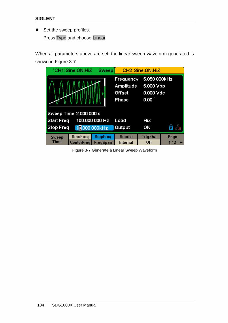
SIGLENT
134 SDG1000X User Manual
Set the sweep profiles.
Press Type and choose Linear.
When all parameters above are set, the linear sweep waveform generated is
shown in Figure 3-7.
Figure 3-7 Generate a Linear Sweep Waveform

SIGLENT
SDG1000X User Manual 135
3.8 Example 8: Generate a Burst Waveform
Generate a burst waveform with 5 cycles. The burst period is 3ms. Use
internal trigger and 0° start phase.
Steps:
Set the burst function.
Press Waveforms, and choose the sine waveform as the burst function.
Set the frequency, amplitude and offset.
1. Press Frequency/Period and choose Frequency which will display in blue
color. Input ‗10‘ from the keyboard and choose the unit ‗kHz‘ to set the
frequency to 10kHz.
2. Press Amplitude/HighLevel to choose Amplitude which will display in blue
color. Input ‗4‘ from the keyboard and choose the unit ‗Vpp‘ to set the
amplitude to 4Vpp.
3. Press Offset/LowLevel to choose Offset which will display in blue color.
Input ‗0‘ from the keyboard and choose the unit ‗Vdc‘ to set the offset to
0Vdc
Set the burst mode.
Press Burst → NCycle, choose N-Cycle Mode. The default setting of the
source is internal.
Set the burst period.
Press Burst Period, input ‗3‘ from the keyboard and choose the unit ‗ms‘ to
set the burst period to 3ms.
Set the start phase.
Press Start Phase, input ‗0‘ from the keyboard and choose the unit ‗°‘ to
set the start phase to 0°.

SIGLENT
136 SDG1000X User Manual
Set the burst cycle.
Press Cycle, Input ‗5‘ from the keyboard and choose the unit ‗Cycle‘ to set
the burst cycle count to 5.
Set the delay.
Press Page 1/2 to choose Delay, and input ‗100‘ from the keyboard and
choose the unit ‗μs‘ to set the delay to 100μs.
When all parameters above are set, the waveform generated is shown in
Figure 3-8.
Figure 3-8 Generate a N-Cycle Burst Waveform
SIGLENT
SDG1000X User Manual 137
3.9 Example 9: Generate an AM Modulation
Waveform
Generate an AM modulation waveform with 80% depth. The carrier is a sine
wave with 10kHz frequency, and the modulating wave is a sine wave with
200Hz frequency.
Steps:
Set the frequency, amplitude and offset of the carrier wave.
1. Press Waveforms , and choose the sine waveform as the carrier wave
2. Press Frequency/Period and choose Frequency which will display in blue
color. Input‘10‘ from the keyboard and choose the unit ‗kHz‘ to set the
frequency to 10kHz
3. Press Amplitude/HighLevel and choose Amplitude which will display in
blue color. Input‘1‘ from the keyboard and choose the unit ‗Vpp‘ to set the
amplitude to 1Vpp.
4. Press Offset/LowLevel and choose Offset which will display in blue color.
Input ‘0‘ from the keyboard and choose the unit ‗Vdc‘ to set the offset to
0Vdc.
Set the modulation type AM and parameters.
1. Press Mod → Type → AM, choose AM. Please notice that the message
shown on the middle left side of the screen is ‗AM‘.
2. Press AM Freq, input ‘200‘ from the keyboard and choose the unit ‗Hz‘ to
set the AM Freq to 200Hz.
3. Press AM Depth, input ‘80‘ from the keyboard and choose the unit ‗%‘ to
set the AM depth to 80%.
4. Press Shape → Sine, to choose sine wave as the modulating waveform.
When all parameters above are set, the waveform generated is shown in
Figure 3-9.
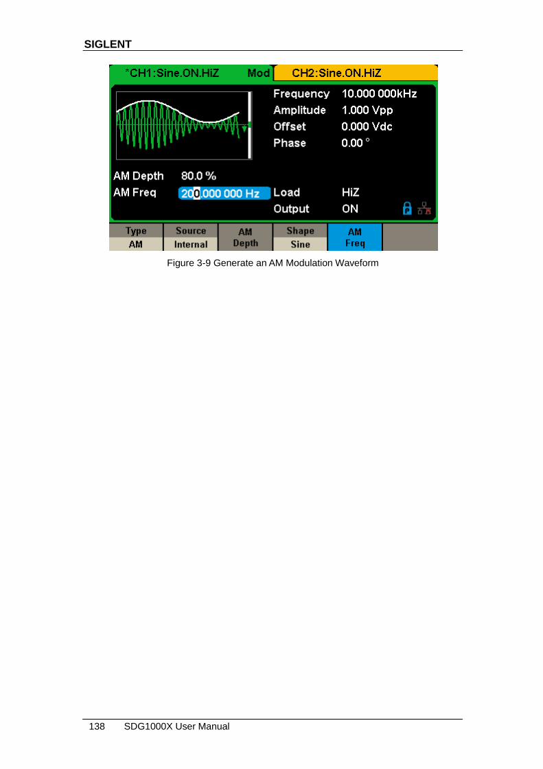
SIGLENT
138 SDG1000X User Manual
Figure 3-9 Generate an AM Modulation Waveform

SIGLENT
SDG1000X User Manual 139
3.10 Example 10: Generate a FM Modulation
Waveform
Generate a FM modulation waveform, the carrier is a sine wave with 10kHz
frequency, and the modulating wave is a sine wave with 1Hz frequency and
2kHz frequency deviation.
Steps:
Set the frequency, amplitude and offset of the carrier wave.
1. Press Waveforms, and choose the sine waveform as the carrier wave.
2. Press Frequency/Period and choose Frequency which will display in blue
color. Input‘10‘ from the keyboard and choose the unit ‗kHz‘ to set the
frequency to 10kHz
3. Press Amplitude/HighLevel and choose Amplitude which will display in
blue color. Input‘1‘ from the keyboard and choose the unit ‗Vpp‘ to set the
amplitude to 1Vpp.
4. Press Offset/LowLevel and choose Offset which will display in blue color.
Input‘0‘ from the keyboard and choose the unit ‗Vdc‘ to set the offset to
0Vdc.
Set the modulation type FM and parameters.
1. Press Mod →Type → FM, choose FM. Please notice that the message
shown on the middle left side of the screen is ‗FM‘.
2. Press FM Freq, input ‗1‘ from the keyboard and choose the unit ‗Hz‘ to set
the FM Freq to 1Hz.
3. Press FM Dev, input ‗2‘ from the keyboard and choose the unit ‗kHz‘ to set
the FM deviation to 2kHz.
4. Press Shape →Sine, to choose sine wave as the modulating waveform.
When all parameters above are set, the waveform generated is shown in
Figure 3-10.

SIGLENT
140 SDG1000X User Manual
Figure 3-10 Generate a FM Modulation Waveform
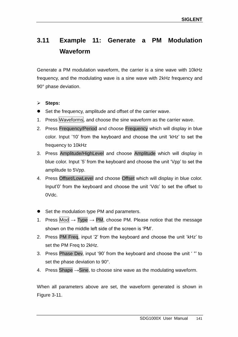
SIGLENT
SDG1000X User Manual 141
3.11 Example 11: Generate a PM Modulation
Waveform
Generate a PM modulation waveform, the carrier is a sine wave with 10kHz
frequency, and the modulating wave is a sine wave with 2kHz frequency and
90° phase deviation.
Steps:
Set the frequency, amplitude and offset of the carrier wave.
1. Press Waveforms, and choose the sine waveform as the carrier wave.
2. Press Frequency/Period and choose Frequency which will display in blue
color. Input ‘10‘ from the keyboard and choose the unit ‗kHz‘ to set the
frequency to 10kHz
3. Press Amplitude/HighLevel and choose Amplitude which will display in
blue color. Input ‘5‘ from the keyboard and choose the unit ‗Vpp‘ to set the
amplitude to 5Vpp.
4. Press Offset/LowLevel and choose Offset which will display in blue color.
Input‘0‘ from the keyboard and choose the unit ‗Vdc‘ to set the offset to
0Vdc.
Set the modulation type PM and parameters.
1. Press Mod → Type → PM, choose PM. Please notice that the message
shown on the middle left side of the screen is ‗PM‘.
2. Press PM Freq, input ‗2‘ from the keyboard and choose the unit ‗kHz‘ to
set the PM Freq to 2kHz.
3. Press Phase Dev, input ‗90‘ from the keyboard and choose the unit ‗ °‘ to
set the phase deviation to 90°.
4. Press Shape →Sine, to choose sine wave as the modulating waveform.
When all parameters above are set, the waveform generated is shown in
Figure 3-11.
SIGLENT
142 SDG1000X User Manual
Figure 3-11 Generate a PM Modulation Waveform
SIGLENT
SDG1000X User Manual 143
3.12 Example 12: Generate a FSK Modulation
Waveform
Generate a FSK modulation waveform with 200Hz key frequency. The carrier
is a sine wave with 10kHz frequency, and the hop frequency is 500Hz.
Steps:
Set the frequency, amplitude and offset of the carrier wave.
1. Press Waveforms, and choose the sine waveform as the carrier wave
2. Press Frequency/Period and choose Frequency which will display in blue
color. Input ‘10‘ from the keyboard and choose the unit ‗kHz‘ to set the
frequency to 10kHz.
3. Press Amplitude/HighLevel and choose Amplitude which will display in
blue color. Input‘5‘ from the keyboard and choose the unit ‗Vpp‘ to set the
amplitude to 5Vpp.
4. Press Offset/LowLevel and choose Offset which will display in blue color.
Input ‘0‘ from the keyboard and choose the unit ‗Vdc‘ to set the offset to
0Vdc.
Set the modulation type FSK and parameters.
1. Press Mod → Type → FSK, choose FSK. Please notice that the message
shown on the middle left side of the screen is ‗FSK‘.
2. Press Key Freq, input ‘200‘ from the keyboard and choose the unit ‗Hz‘ to
set the key frequency to 200 Hz.
3. Press Hop Freq, input ‗500‘ from the keyboard and choose the unit ‗Hz‘ to
set the hop frequency to 500Hz.
When all parameters above are set, the waveform generated is shown in
Figure 3-12.

SIGLENT
144 SDG1000X User Manual
Figure 3-12 Generate a FSK Modulation Waveform

SIGLENT
SDG1000X User Manual 145
3.13 Example 13: Generate an ASK Modulation
Waveform
Generate an ASK modulation waveform with 500Hz key frequency. The carrier
is a sine wave with 5kHz frequency.
Steps:
Set the frequency, amplitude and offset of the carrier wave.
1. Press Waveforms, and choose the sine waveform as the carrier wave
2. Press Frequency/Period and choose Frequency which will display in blue
color. Input ‗5‘ from the keyboard and choose the unit ‗kHz‘ to set the
frequency to 5kHz
3. Press Amplitude/HighLevel and choose Amplitude which will display in
blue color. Input ‗5‘ from the keyboard and choose the unit ‗Vpp‘ to set the
amplitude to 5Vpp.
4. Press Offset/LowLevel and choose Offset which will display in blue color.
Input ‗0‘ from the keyboard and choose the unit ‗Vdc‘ to set the offset to
0Vdc.
Set the modulation type ASK and parameters.
1. Press Mod →Type → ASK, choose ASK. Please notice that the message
shown on the middle left side of the screen is ‗ASK‘.
2. Press Key Freq, input ‗500‘ from the keyboard and choose the unit ‗Hz‘ to
set the key frequency to 500 Hz.
When all parameters above are set, the waveform generated is shown in

SIGLENT
146 SDG1000X User Manual
Figure 3-13.
Figure 3-13 Generate an ASK Modulation Waveform

SIGLENT
SDG1000X User Manual 147
3.14 Example 14: Generate a PSK Modulation
Waveform
Generate a PSK modulation waveform with 200Hz key frequency. The carrier
is a sine wave with 1kHz frequency.
Steps:
Set the frequency, amplitude and offset of the carrier wave.
1. Press Waveforms, and choose the sine waveform as the carrier wave
2. Press Frequency/Period and choose Frequency which will display in blue
color. Input ‗1‘ from the keyboard and choose the unit ‗kHz‘ to set the
frequency to 1kHz
3. Press Amplitude/HighLevel and choose Amplitude which will display in
blue color. Input ‗5‘ from the keyboard and choose the unit ‗Vpp‘ to set the
amplitude to 5Vpp.
4. Press Offset/LowLevel and choose Offset which will display in blue color.
Input ‗0‘ from the keyboard and choose the unit ‗Vdc‘ to set the offset to
0Vdc.
Set the modulation type PSK and parameters.
1. Press Mod → Type → Page 1/2 → PSK, choose PSK. Please notice that
the message shown on the middle left side of the screen is ‗PSK‘.
2. Press Key Freq, input ‗200‘ from the keyboard and choose the unit ‗Hz‘ to
set the key frequency to 200 Hz.
3. Press Polarity → Positive.
When all parameters above are set, the waveform generated is shown in
Figure 3-14.

SIGLENT
148 SDG1000X User Manual
Figure 3-14 Generate a PSK Modulation Waveform

SIGLENT
SDG1000X User Manual 149
3.15 Example 15: Generate a PWM Modulation
Waveform
Generate a PWM modulation waveform with 200Hz key frequency. The carrier
is a pulse wave with 5kHz frequency.
Steps:
Set the frequency, amplitude and offset of the carrier wave.
1. Press Waveforms , and choose the Pulse waveform as the carrier wave
2. Press Frequency/Period and choose Frequency which will display in blue
color. Input ‗5‘ from the keyboard and choose the unit ‗kHz‘ to set the
frequency to 5kHz
3. Press Amplitude/HighLevel and choose Amplitude which will display in
blue color. Input ‗5‘ from the keyboard and choose the unit ‗Vpp‘ to set the
amplitude to 5Vpp.
4. Press Offset/LowLevel and choose Offset which will display in blue color.
Input ‗0‘ from the keyboard and choose the unit ‗Vdc‘ to set the offset to
0Vdc.
5. Press PulWidth/DutyCycle and choose PulWidth which will display in blue
color. Input ‗40‘ from the keyboard and choose the unit ‗us‘ to set the
PulWidth to 40us
Set the modulation type PWM and parameters.
1. Press Mod, Please notice that the message shown on the middle left side
of the screen is ‗PWM ‘.
2. Press PWM Freq, input ‗200‘ from the keyboard and choose the unit ‗Hz‘ to
set the PWM Freq to 200Hz.
3. Press Width Dev, input ‗20‘ from the keyboard and choose the unit ‗us‘ to
set the width deviation to 20us
When all parameters above are set, the waveform generated is shown in
Figure 3-15.

SIGLENT
150 SDG1000X User Manual
Figure 3-15 Generate a PWM Modulation Waveform
SIGLENT
SDG1000X User Manual 151
3.16 Example 16: Generate a DSB-AM Modulation
Waveform
Generate a DSB-AM modulation waveform with 100Hz modulating frequency.
The carrier is a sine wave with 2kHz frequency.
Steps:
Set the frequency, amplitude and offset of the carrier wave.
1. Press Waveforms, and choose the sine waveform as the carrier wave.
2. Press Frequency/Period and choose Frequency which will display in blue
color. Input ‗2‘ from the keyboard and choose the unit ‗kHz‘ to set the
frequency to 2kHz
3. Press Amplitude/HighLevel and choose Amplitude which will display in
blue color. Input ‗4‘ from the keyboard and choose the unit ‗Vpp‘ to set the
amplitude to 4Vpp.
4. Press Offset/LowLevel and choose Offset which will display in blue color.
Input ‗0‘ from the keyboard and choose the unit ‗Vdc‘ to set the offset to
0Vdc.
Set the modulation type DSB-AM and parameters.
1. Press Mod → Type → DSB-AM, choose DSB-AM. Please notice that the
message shown on the middle left side of the screen is ‗DSB-AM ‘.
2. Press DSB Freq, input ‗100‘ from the keyboard and choose the unit ‗Hz‘ to
set the DSB Freq to 100Hz.
When all parameters above are set, the waveform generated is shown in
Figure 3-16.

SIGLENT
152 SDG1000X User Manual
Figure 3-16 Generate a DSB-AM Modulation Waveform
SIGLENT
SDG1000X User Manual 153
4 Troubleshooting
4.1 General Inspecting
After receiving a new SDG1000X Series Function/Arbitrary Generator please
inspect the instrument as followed:
1. Inspect the shipping container for damage.
Keep the damaged shipping container or cushioning material until the
contents of the shipment have been checked for completeness and the
instrument has been checked mechanically and electrically.
2. Inspect the entire instrument.
In case there is any mechanical damage or defect, or the instrument does not
operate properly or fails in the performance tests, notify the SIGLENT sales
representative.
If the shipping container is damaged, or the cushioning materials show signs
of stress, notify the carrier as well as the SIGLENT sales department. Keep
the shipping materials for carrier‘s inspection.
3. Check the accessories.
Accessories supplied with the instrument are listed in ―Appendix A‖. If the
contents are incomplete or damaged, notify the SIGLENT sales
representative.

SIGLENT
154 SDG1000X User Manual
4.2 Troubleshooting
1. After the generator is powered on, if the screen remains dark please
do as the following steps:
(1) Check the power cable‘s connection.
(2) Ensure the power switch is turned on.
(3) After the inspections above, restart the generator.
(4) If the generator still doesn‘t work after checking, please contact SIGLENT.
2. If there is no waveform output after setting the parameters, please do
as the following steps:
(1) Check whether the BNC cable has a good connection to the output port.
(2) Check whether the output keys have been turned on.
(3) If the generator still doesn‘t work after checking, please contact SIGLENT.
SIGLENT
SDG1000X User Manual 155
5 Service and Support
5.1 Maintenance summary
SIGLENT warrants that the products it manufactures and sells will be free
from defects in materials and workmanship for three years from the date of
shipment from an authorized SIGLENT distributor. If a product is proved to be
defective within the warranty period, SIGLENT will provide repair or replace
the unit as described in the complete warranty statement.
To arrange for service or obtain a copy of the complete warranty statement,
please contact your nearest SIGLENT sales and service office. Except as
provided in this summary or the applicable warranty statement, SIGLENT
makes no warranty of any kind, express or implied, including but not limited to
the implied warranties of merchantability and special applicability. In no event
shall SIGLENT be liable for indirect, special or consequential damages.
SIGLENT
156 SDG1000X User Manual
5.2 Contact SIGLENT
SIGLENT TECHNOLOGIES CO., LTD
Address: 3/F, NO.4 building, Antongda Industrial Zone, 3rd Liuxian Road, 68th
District, Baoan District, Shenzhen, P.R. China
Tel: 400-878-0807
E-mail: [email protected]
http: //www.siglent.com

SIGLENT
SDG1000X User Manual 157
6 Appendix
Appendix A: Accessories
SDG1000X Series Function/Arbitrary Waveform Generator Accessories:
Standard Accessories:
Quick Start Guide
A Calibration Report
A Product Certification
A CD (including a arbitrary editing software EasyWave)
A Power Line that fits the standard of the destination country
A USB Cable
Optional Accessories:
USB-GPIB adapter (IEEE 488.2)
SPA1010 Power Amplifier
20dB Attenuator
SIGLENT
158 SDG1000X User Manual
Appendix B: Daily Maintenance and Cleaning
Daily Maintenance
Do not store or leave the instrument in where the display screen will be
exposed to direct sunlight for a long period of time.
CAUTION: To avoid damage to the instrument, do not expose it to
spray, liquid, or solvent.
Cleaning
If the instrument requires cleaning, disconnect it from all power sources and
clean it with a mild detergent and water. Make sure the instrument is
completely dry before reconnecting it to a power source.
To clean the exterior surface, perform the following steps:
1. Remove loose dust on the outside of the instrument with a lint-free cloth.
When cleaning the screen, be careful to avoid scratching the transparent
plastic protective screen.
2. Use a soft cloth dampened with water to clean the instrument.
WARNING: To avoid any damage to the surface of the instrument, do
not use any abrasive or chemical cleaning agents.