user manual/ operation guide - leadsolarenergy.com datasheet/leadsolar ls1400 use… ·...
TRANSCRIPT

LeadSolar LS1400 User Manual 1
User Manual/ Operation Guide
LeadSolar LS1400
Single-Phase Grid-connected PV Microinverter
Ver 2.2
LeadSolar Energy(wuxi) Co, Ltd.
A308, 530 Building, Qing Yuan Rd, Wuxi New District, Wuxi, China, 214135
Tel: +86 510 81817488
Fax: +86 510 81817475
Email: [email protected]
Web: www.leadsolarenergy.com
Copyright © 2015 LeadSolar Energy. All rights reserved.

LeadSolar LS1400 User Manual 2
Contents
Notes............................................................................................................................................................... 3
Safety Instructions ...................................................................................................................................... 3
Explanation of Symbols .............................................................................................................................. 4
LeadSolar LS1400 System Introduction .......................................................................................................... 6
Installation ...................................................................................................................................................... 9
Compatibility & Capacity ............................................................................................................................ 9
Packaging .................................................................................................................................................... 9
Required Parts & Tools ............................................................................................................................. 10
Lightning Surge Suppression..................................................................................................................... 10
Installation Procedure .................................................................................................................................. 11
Preparation ............................................................................................................................................... 11
Installation ................................................................................................................................................ 11
Step 1: Measure Grid AC Voltage at Electrical Utility Connection ....................................................... 12
Step 2: Attach microinverters to PV Racking ........................................................................................ 12
Step 3: Connect microinverter’s AC cable ............................................................................................ 13
Step 4: Terminate unused end of AC cable for each branch ................................................................ 13
Step 5: Install AC branch circuit junction box ....................................................................................... 14
Step 6: Ground system & microinverters ............................................................................................. 15
Step 7: Complete the installation map ................................................................................................. 15
Step 8: Install the Link nearby the AC main .......................................................................................... 15
Step 9: Connect microinverters to PV modules .................................................................................... 16
Step 10: Register microinverters .......................................................................................................... 16
LeadSolar Microinverter System Operation Guide....................................................................................... 17
Microinverter System Trouble Shooting Guide ............................................................................................ 18
Replacing or Adding a Microinverter ............................................................................................................ 19
Rapid shutdown ............................................................................................................................................ 20
Technical Data .............................................................................................................................................. 21
Technical Considerations .......................................................................................................................... 21
Specifications ............................................................................................................................................ 21

LeadSolar LS1400 User Manual 3
Notes
This user manual describes the assembly, installation, commissioning, and maintenance and failure
identification of the LeadSolar microinverter. To reduce the risk of electrical shock and ensure the
safe installation and operation, the following symbols are used in the manual to indicate dangerous
conditions.
SAVE THESE INSTRUCTIONS-This manual contains important instructions for model LS1400
that shall be followed during installation and maintenance of the microinverter.
All information, specifications and illustrations in this manual are those in effect at the time of
printing. LeadSolar reserves the right to change specifications or design without notice. For latest
information about our products, please visit www.leadsolarenergy.com .
All trademarks are recognized as the property of their respective owners.
WARNING:
This indicates a safety hazard that could cause personal injury or equipment
malfunction. Follow these instructions carefully to avoid or reduce the risk.
NOTE:
This indicates important information that is critical to optimizing system
performance.
Safety Instructions
Follow local installation codes. Make sure to adhere to all applicable national and local
electrical codes during installation. Only qualified personnel should install or replace
LeadSolar Microinverters.
No DIY repairs. Users must never attempt to repair or modify the LeadSolar Microinverter
themselves. If the microinverter fails to operate, contact LeadSolar customer service for repair
or replacement. Tampering with or opening the hardware will void the warranty.
Read the instructions. Read all instructions and cautionary notes before installing or using
LeadSolar hardware.
Disconnect safely. Disconnect the AC power grid connection first before disconnecting the
PV module from the LeadSolar Microinverter.
Microinverter can get hot. The majority of the LeadSolar Microinverter is a heat sink.
Under normal operating conditions, the temperature is 59°F (15°C), but it can reach 176°F
(80°C) under extreme conditions. To reduce risk of burns, use caution when working with

LeadSolar LS1400 User Manual 4
microinverters.
It’s already fine-tuned for your region. Be aware that the LS1400 has different default
factory settings for the applications in different regions throughout the world. The LS1400 do
not need field adjustment or tuning. It will start to deliver power to the electric grid
automatically after installation.
This unit or system is provided with fixed trip limits and shall not be aggregated above
30 kW on a single Point of Common Connection.
Explanation of Symbols
The following symbols are shown on the microinverter:
Symbol Explanation
Treatment
To comply with European Directive 2002/96/EC on waste Electrical and
Electronic Equipment and its implementation as national law, electrical
equipment that has reached the end of its life must be collected separately
and returned to an approved recycling facility. Any device no longer
required must be returned to an authorized dealer or approved collection
and recycling facility.
Traitement
Conformément à la directive européenne 2002/96/EC relative aux déchets
d’équipements électriques et électroniques, et à sa transposition dans la
législation nationale, les appareils électriques qui ont atteint la fin de leur
durée de vie doivent être collectés séparément et être soumis à un
recyclage respectueux de l’environnement. Tout appareil usagé doit être
retourné à un revendeur autorisé ou à une organisation approuvée de
collecte ou de recyclage.
UL1741
CSA C22.2 NO. 107.1-01
UL 1741 Standard for Safety for Inverters, Converters, Controllers and
Interconnection System Equipment for use with Distributed Energy
Resources. CSA-C22.2 No. 107.1-01 - General Use Power Supplies
UL 1741 Norme de sécurité pour les onduleurs, convertisseurs,
contrôleurs et de l'équipement d'interconnexion de systèmes pour une
utilisation avec des ressources énergétiques décentralisées. CSA C22.2
NO.107.1-01 - Fournitures générales d'utilisation de puissance
Do not come within 8 inches (20cm) of the microinverter for any length
of time while it is in operation.
Ne pas entrer dans un rayon minimum de 8 pouces (20 cm) du micro-
onduleur pour toute longueur de temps lors de l’opération.
CAUTION!
Risk of Electric Shock, Do Not Remove Cover. No User Serviceable Parts
Inside. Refer Servicing To Qualified Service Personnel. Both ac and dc
voltage sources are terminated inside this equipment. Each circuit must be

LeadSolar LS1400 User Manual 5
individually disconnected before servicing. When the photovoltaic array
is exposed to light, it supplies a dc voltage to this equipment.
Attention!
Risque de choc électrique, ne pas enlever le couvercle. Aucune pièce
interne réparable par l’utilisateur. Toute réparation doit être uniquement
confiée à du personnel qualifié. A l’intérieur de l’onduleur on retrouve 2
tensions AC et DC. Chaque circuit doit être déconnecté individuellement
avant chaque entretien. Lorsque le panneau photovoltaïque est exposé à la
lumière, il fournit une tension DC à cet appareil.
CAUTION!
Hot surfaces – To reduce the risk of burns – Do not touch
Attention!
Les surfaces chaudes – pour réduire le risque de brûlure – Ne pas toucher
Read manual first
Please read the installation manual first before installation, operation and
maintenance.
Lire d’abord le manuel
Veuillez lire le manuel d’installation avant toute installation, opération et
maintenance.
5 minutes
CAUTION!
Do not remove cover until 5 minutes after disconnecting all sources of
supply.
Attention!
Ne pas enlever le couvercle durant 5 minutes après la déconnexion
électrique totale.

LeadSolar LS1400 User Manual 6
LeadSolar LS1400 System Introduction
Welcome to the growing family of high performance LS1400 microinverter system owners. The
LeadSolar Microinverter System is among the most advanced inverter systems for use in utility-
interactive photovoltaic applications. This system is highly reliable, highly efficient, and easy to
install. The three key elements of a LeadSolar Microinverter System include:
• LeadSolar Microinverter
• LeadSolar Link™ Communications Gateway
• LeadSolar Management™ web-based monitoring and analysis software
For most of the PV applications, the LeadSolar microinverter system will benefit the system owner
from the initial system design throughout to the entire lifetime of the system.
LeadSolar Smart Solar: More Flexibility, More Productivity
Microinverters are what make a distributed solar system possible. Conventional solar grids string
numerous solar panels together and connect them all to a single, central grid-tied inverter. This
works well if all panels are under uniform conditions, but efficiency is lost when some of the panels
are shaded by cloud, trees, or chimneys. Particularly for roof-top residential and commercial PV
applications, the output power from a central inverter architecture is usually not maximized, no
matter how advanced PV modules or inverter technologies are used.
Traditional String Inverter LeadSolar Microinverter

LeadSolar LS1400 User Manual 7
Warranty (yrs) 5 15 - 25
System Risks The whole system Local
Maintenance Professionally trained technician on
site repair
Remote support and problem
fixing
DC High Voltage Yes No
DC Arc Fire Risk Yes No
Electric Generation
Control Cannot turn off in daylight Automatic turn off
System Design High voltage DC wiring Flexible
Accessories DC conduit, junction boxes, etc. AC connection
Installation Separate inverter installation Inverter integrated with solar
panel
In the LeadSolar microinverter system, PV modules will not be connected to a central inverter.
Instead, each PV module has its own inverter to feed the harvested energy from PV module to
electric grid. The maximum power point tracking (MPPT) controller embedded in the
microinverter will monitor the operation of the PV module in real time and maintain a maximum
power point. If one or several PV modules in the system are shaded, the output power of these
modules will drop but the other modules will not be affected and continue to output at their
maximum power level. LeadSolar’s smart solar power system can typically harvest 15% - 25%
more electric energy than a traditional system with one central inverter.
Reliability
The LeadSolar microinverter provides highly reliable solar installations by removing failure-prone
central inverters. With no single point of system failure, LeadSolar Microinverters are designed to
operate at full power with ambient temperatures as high as 60°C. The microinverter housing is
designed for outdoor installation and complies with the NEMA 6 environmental enclosure rating
standard. LeadSolar Energy uses the harshest possible testing conditions; each unit is both tested
at the factory and tracked in the field.
System Monitoring & Easy Maintenance
The LeadSolar Link™ Communications Gateway provides a unique and convenient way to monitor
your system’s operation and performance.
To install a LeadSolar Link Gateway, just plug it into any wall socket in your house and use the
provided Ethernet cable to connect it to your broadband router or modem. Then the Gateway will
automatically start to work and communicate with the microinverters in your system. The collected
system operation data will be reported to the LeadSolar Management web server. The Management
software presents current and historical system performance trends, and it informs you of PV
system status.

LeadSolar LS1400 User Manual 8
Simple Design & Easy Installation
LeadSolar Microinverters have a simple design for easy installation. Traditional design procedures
(string calculations, panel orientation, etc.) are not necessary for LeadSolar microinverter systems.
Simply attach the microinverter to a compatible PV modules and connect the DC and AC cables to
the panel and AC grid. The installation is finished and the system is ready to work.
The system is open and can accommodate new panels at any time. This allows users to adopt solar
power at their own pace, and as their budget allows. One panel’s failure does not impede others at
all. Maintenance, repair, and replacement do not require the whole system to be shut down -- only
the panel that needs repair. Distributed systems eliminate the risk of personnel exposure to lethal
doses of voltage (up to 600V), which is common in a string or central inverter system.
LeadSolar LS1400 User Manual 9
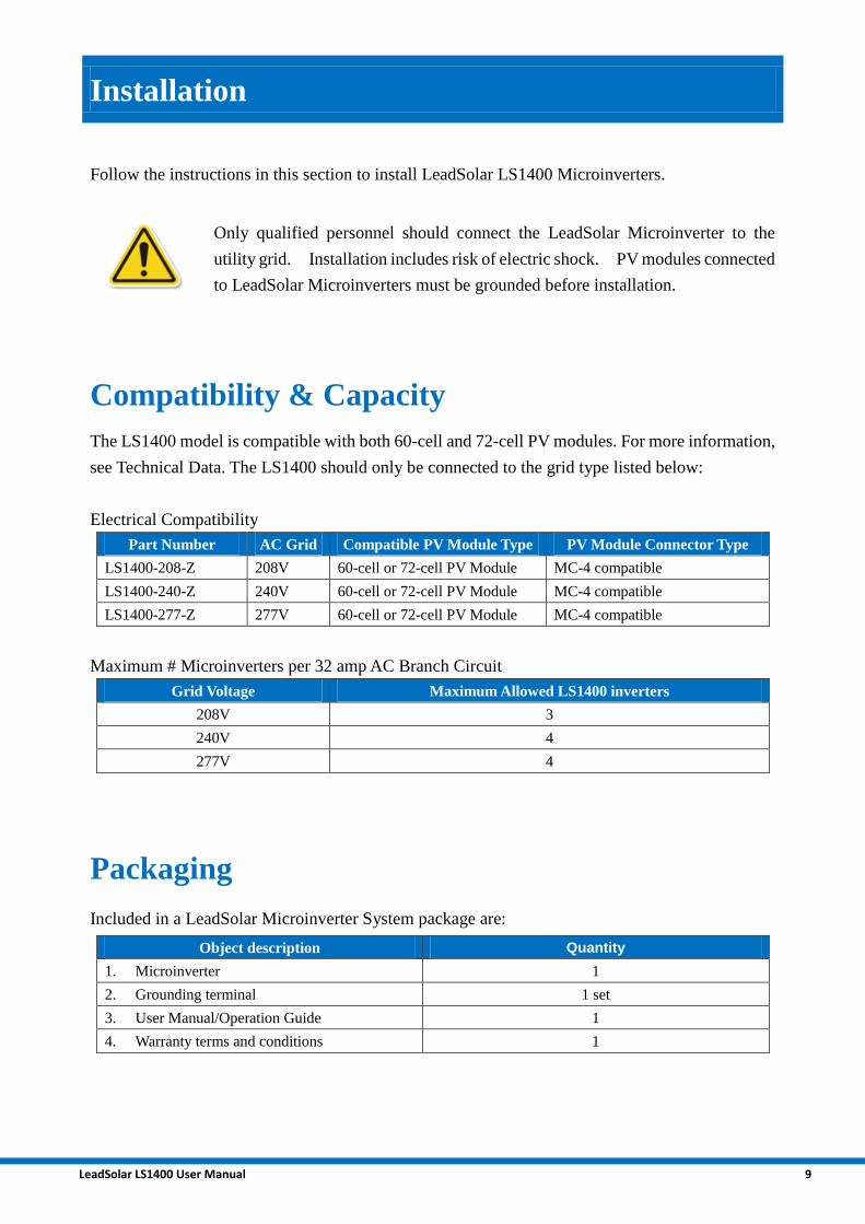
Installation
Follow the instructions in this section to install LeadSolar LS1400 Microinverters.
Only qualified personnel should connect the LeadSolar Microinverter to the
utility grid. Installation includes risk of electric shock. PV modules connected
to LeadSolar Microinverters must be grounded before installation.
Compatibility & Capacity
The LS1400 model is compatible with both 60-cell and 72-cell PV modules. For more information,
see Technical Data. The LS1400 should only be connected to the grid type listed below:
Electrical Compatibility
Part Number AC Grid Compatible PV Module Type PV Module Connector Type
LS1400-208-Z 208V 60-cell or 72-cell PV Module MC-4 compatible
LS1400-240-Z 240V 60-cell or 72-cell PV Module MC-4 compatible
LS1400-277-Z 277V 60-cell or 72-cell PV Module MC-4 compatible
Maximum # Microinverters per 32 amp AC Branch Circuit
Grid Voltage Maximum Allowed LS1400 inverters
208V 3
240V 4
277V 4
Packaging
Included in a LeadSolar Microinverter System package are:
Object description Quantity
1. Microinverter 1
2. Grounding terminal 1 set
3. User Manual/Operation Guide 1
4. Warranty terms and conditions 1

LeadSolar LS1400 User Manual 10
Required Parts & Tools
During installation, the following parts and tools may be required in addition to the hardware
provided:
LeadSolar Parts:
• LeadSolar Quick Connect Cables
The LeadSolar quick connect cable is designed to facilitate the system installation. Order the
correct cable type according to the grid voltage type.
• Cable clips, sealing caps, as needed (for any unused drops on the cable)
• Terminators, as needed (one needed at the end of each AC branch circuit)
Other Items
• AC junction boxes
• Gland or strain relief fitting (one per AC junction box)
• Continuous grounding conductor, grounding washers
• Number 2 and 3 Phillips screwdrivers
• Torque wrench, sockets, wrenches for mounting hardware
• Adjustable wrench or open-ended wrench (for terminators)
• Handheld mirror (to view indicator lights on the undersides of the microinverters)
Lightning Surge Suppression
PV systems are usually installed in open fields or on rooftops -- places where lighting can strike.
Lightning causes drastic voltage spikes in solar panels, which may damage equipment. While
LeadSolar Energy Microinverters have built-in surge protection, this may not always protect all
equipment from the energy spike caused by lighting. Additional surge protection devices are
strongly suggested.
Additional surge protection devices are strongly recommended to fully protect
your system.

LeadSolar LS1400 User Manual 11
Installation Procedure
Preparation
Installation tools: multimeter, allen wrench, impact drill, screwdriver and manual wrench
Make sure AC & DC plugs are drained of electrical charge before
installation and maintenance! If the DC side has recently been
disconnected, capacitors will still contain a residual charge. Wait for at least
5 minutes to ensure the capacitors are no longer electrified.
For optimal performance, inverters should be installed by a technician.
Installation
Read entire installation procedure before installing. The following
procedure must be strictly followed for a proper installation.
Step 1: Measure Grid AC Voltage at Electrical Utility Connection
Step 2: Attach microinverters to PV Racking
Step 3: Connect microinverter’s AC cable
Step 4: Terminate unused end of AC cable for each branch
Step 5: Install AC branch circuit junction box
Step 6: Ground system & microinverters
Step 7: Complete the installation map
Step 8: Install the Link nearby the AC main
Step 9: Connect microinverters to PV modules

LeadSolar LS1400 User Manual 12
Step 10: Register microinverters
DO NOT connect LeadSolar Microinverters to the utility grid to energize
the AC circuit(s) until you have completed all of the installation procedures.
Step 1: Measure Grid AC Voltage at Electrical Utility Connection
Measure AC line voltage at the point of common utility connection coupling to ensure it is within
the proper range for the microinverter’s operation. Acceptable ranges are shown as below:
Single phase 208V AC: 183 to 232 VAC(L1 to L2) or
Single phase 240V AC: 211 to 264 VAC(L1 to L2) or
Single phase 277V AC: 244 to 305 VAC(L1 to L2)
Distribution PanelMultimeter
Check cable voltage rating before installation. For LeadSolar Quick
Connect cables, voltage rating is marked on the cable’s label. Never use
cables with insufficient voltage rating for intended use.
Step 2: Attach microinverters to PV Racking
The position for the microinverter on the PV racking is flexible and is usually determined before
installation.
Put the microinverter under the PV module, out of direct sunlight. Also, leave at least 0.6in (1.5cm)
clearance between the roof and the bottom of the microinverter; and at least 0.6 in (1.5cm) clearance
between the back of the PV module and the top of the microinverter.

LeadSolar LS1400 User Manual 13
Step 3: Connect microinverter’s AC cable
Do NOT exceed the maximum number of microinverters in an AC branch
circuit as specified in this manual.
Before connecting the AC cables of the microinverter, check the number of the microinverters in
each AC branch circuit. Beginning with the end of the branch, connect one of the AC cable of the
last microinverter in a branch to the adjacent microinverter. Then repeat this step for each
microinverter in a branch and eventually any adjacent microinverter’s AC cables should be
connected. Then connect the 2nd AC cable of the first microinverter to the AC cable running from
the junction box.
Step 4: Terminate unused end of AC cable for each branch
For the microinverter located at the end of a branch
circuit, one of its AC cables is not connected to other
microinverters.
It is unsafe to leave this AC cable exposed to the field,
since it will still be energized and may bring electrical
hazard. These cables should be terminated with

LeadSolar LS1400 User Manual 14
protective caps.
Never leave unused AC cables open/floating in the system. Terminate the
unused end of an AC cable with provided protective caps. Terminate the
unused end of the AC cable for each branch.
Step 5: Install AC branch circuit junction box
Risk of Electrical Shock. Remove AC power from system before installing
the AC branch circuit junction box. Each AC branch circuit must have a
32A maximum circuit breaker.
Additional lightning protection equipment may be necessary for some
locations.
For each AC branch, an AC junction box is required for routing the AC grid to the microinverters.
Follow the steps listed below carefully to install the AC junction box:
1. Install the AC junction box to a proper
location of the branch circuit. The most
common location for the junction box is the
beginning or middle of an AC branch. For the
latter location, be aware that two
microinverters in one AC branch circuit have
unused AC cables to be terminated.
2. Put the AC cable from inverter side into the junction box with anti-pull accessories and proper
washers.
3. Pay attention to the wire colors in the cable. The electrical codes usually have the following
specification for the wire color: Red-Hot wire; Black- Neutral wire; Ground: yellow/green
double color wire.
4. Connect and secure the cable from AC grid side to the terminals inside the junction box. This
step will connect the microinverter to the AC grid. Make sure the AC grid power is always
removed during this step.
5. Close the cover of the AC junction box tightly by securing the screws on the corners of the
cover.
NOTE: Wire colors are listed in the following table
Grid Microinverter Wire color
L1 Red
L2 Black
GND(Ground) Green/Yellow

LeadSolar LS1400 User Manual 15
Step 6: Ground system & microinverters
For safety considerations, all non-current carrying elements in a photovoltaic system (including PV
module, PV racking and microinverter case) must be securely grounded before operation. Choose
one of the two methods below for system grounding:
1. Run a continuous grounding conductor from each microinverter to the AC grounding electrode.
This is the most common method. Connect the PV module frame, PV racking and
microinverter case to this grounding conductor by using grounding washers. Tighten the
grounding clamp screw.
2. For systems with PV racking that is already grounded, securely attach the PV module and
microinverter to the grounded PV racking by using washers and tightening the grounding
clamp screw.
Never start system operation before finishing system grounding. The
ground fault detection device (GFDI) inside the microinverter may be
tripped if the system is not securely grounded.
Step 7: Complete the installation map
We need series numbers of installed microinverters for registering in our service later..
The Installation Map is a diagrammatic representation of the physical location of each
microinverter in you PV installation. The virtual array in our web APP is created from the map you
created. You can create a blank according to your previous system design before placing the
microinverters to the arrays.
Each microinverter has a removable serial number label located on the top of our microinverters,
when installing the microinverters, remove the serial number labels located and place in the correct
order on your drawing of the system. Remember to keep a copy of the installation for your records.
You are not done yet! Complete the Operation Guide section to begin use
properly. It is important to record the series number of the microinverters
and communication gateways for adding these devices in our database.
Step 8: Install the Link nearby the AC main
Link is an integral component of the LeadSolar Energy Microinverter system. Its functions as a
communication gateway and monitors the microinverters that are connected to the PV modules.
The Link collects energy and performance data from the microinverters via on-site AC power lines.

LeadSolar LS1400 User Manual 16
LeadSolar recommends that the Link be placed as close to the AC mains as possible. This ensures
that the Link receives the strongest possible signal from each microinverter. The Link must be
indoors and can be placed on a table or mounted on the wall. The AC outlet that the Link plugged
in must be close to the AC mains and keep the same phase with the point that PV system tied in.
Step 9: Connect microinverters to PV modules
Connect the each microinverter DC input terminals to the adjacent four PV modules output
terminals through the Quick Connect cable. Check your work to make sure all the microinverters
in the system are securely connected to the PV modules.
Step 10: Register microinverters
Go to www.leadsolarenergy.net. For more information, refer to the “LeadSolar Smart Grid Web
Application”.

LeadSolar LS1400 User Manual 17
LeadSolar Microinverter System Operation Guide
Congratulations on finishing the PV system installation! Follow these steps to begin operation:
1. Close the AC circuit breaker for each branch circuit (usually 32A rating breakers).
2. Close the main circuit breaker for the entire system. This breaker should be chosen based on
your PV system capacity. The microinverter system will begin operation in about 1 minutes.
3. Plug the Ethernet cable into the Ethernet port on the Link, and the other end of the cable into
a spare port on the broadband router. Place the Link so that its AC cord can reach this outlet.
Try unplugging any other device that may be sharing the outlet with the Link,
4. The Link must be obtain a DHCP (Dynamic Host Configuration Protocol) IP address and have
a path to the internet after power on. And then the Link will query the data of the
microinverters that registered in our website.
5. Login to your user account on www.leadsolarenergy.com and monitor the operation of your
system in real-time.
Please note that for the first time power up after installation, the system may need ~10 minutes to
establish communication between each microinverter and LeadSolar Link Gateway. This portal
will display the power generated by each microinverter, along with fault reports for quick trouble
shooting.
The basic operation status of each microinverter is also displayed by the indicator LEDs on each
microinverter. It is recommended to take a quick check of the LEDs after initial power up. Each
microinverter will self-check its connection after being connected to DC Power. The Status LED
will blink green ten times to indicate continued connection. A solid red status indicates
disconnection -- make sure all plugs are fully connected.
The table below summarizes the description of the LED indicators’ operation after self-checking:
LED Status Descriptions
Solid Green Producing power normally
Flash Green 2s/times Ready

LeadSolar LS1400 User Manual 18
Microinverter System Trouble Shooting Guide
Leave troubleshooting to qualified electrical professionals.
Do not unplug the microinverter during operation. This may damage the
microinverter and expose the operator to electrical hazard. First open the
AC circuit breaker; then disconnect the AC grid; then unplug the inverter
from the PV module. (To disconnect the entire system from the AC grid,
open the main circuit breaker. To disconnect a particular AC branch circuit,
open the circuit breaker connected to that branch.)
Please follow the steps below for troubleshooting system problems:
1. Make sure the AC grid voltage and frequency are both in the allowed range for proper
operation. Refer to the microinverter datasheet for the accepted AC grid conditions.
2. Check the connection of the system. Disconnect the AC side and then the DC input side of the
microinverter.
3. Check the PV module open circuit voltage. The open-circuit voltage of PV module should stay
in the range specified in the microinverter datasheet.
4. Reconnect the DC side cable and check the LED status of the microinverter. If the green LED
light is flashing, the DC connection is good.
5. Check the AC grid side connection. If the entire system doesn’t work, check the main AC
circuit breaker. For a particular branch problem, check the AC circuit breaker connected to that
branch. For a particular microinverter problem in a branch, check the AC cable connection of
that microinverter. If the LED is solid green after blinking 10 times, the grid connection is
good.
Do Not attempt to repair the microinverter. This will void the warranty and
can bring electrical hazard to those attempting it. Contact LeadSolar
customer support to initiate an inverter return process.

LeadSolar LS1400 User Manual 19
Replacing or Adding a Microinverter
Identify the circuit breaker for the branch in which a microinverter will be
replaced or added. Open that circuit breaker before starting the
replacement/adding procedure.
Follow the steps below to replace a microinverter:
1. Disconnect branch AC circuit breaker
2. Cover PV module connected to microinverter to be replaced
3. Disconnect AC connection cable from adjacent microinverter
4. Disconnect PV module from microinverter
5. Remove failed microinverter from PV rack
6. Follow Installation Instructions to install new microinverter
7. Remove PV module cover and close branch circuit breaker
8. New microinverter will begin operating in 1 minutes
9. Register new microinverter on LeadSolar website
New PV modules and microinverters can be added to existing distributed system any time. Please
follow the Installation section to complete the new installation of PV modules and microinverters.

LeadSolar LS1400 User Manual 20
Rapid shutdown
LeadSolar Microinverter system is compliant with the NEC 2014 and NEC 2017 Rapid Shutdown
code requirements, without any additional device. This function is designed to decrease the risk
emergency responders—particularly firefighters—face when they work on a fire at a building with
a PV system.
Follow the steps below to shutdown the system safely :
1.Disconnect the main AC circuit breaker.
2.Disconnect the branch AC circuit breakers.
Then, the whole system will be under 80V, which meet the 2014 NEC article 690.12 Rapid
Shutdown code requirements.

LeadSolar LS1400 User Manual 21
Technical Data
Technical Considerations
The LeadSolar LS1400 Microinverter is electrically compatible with most 60-cell or 72-cell PV
modules. Be sure to verify the voltage and current specifications of your PV module match those
of the microinverter. For more information, refer to our list of compatible PV modules.
The PV module’s maximum open circuit voltage must not exceed the
microinverter’s maximum input voltage.
The output voltage and current of the PV module depends on the quantity, size and temperature of
the PV cells, as well as the isolation on each cell. The highest PV module output voltage occurs
when the temperature of the cells is the lowest and the PV module is at open circuit (not operating).
The maximum short circuit current rating of the PV module must be equal to or less than the
maximum input DC short circuit current rating of the microinverter.
Specifications
INPUT DATA [DC]
Recommended PV module power (STC) 230 - 350W
Maximum input voltage 60V
MPPT voltage range(Full Power) 32 - 45V
Operating voltage range 22 - 55V
Number of MPPT 4
Maximum input string 4
Maximum DC short circuit current 60A (15A per MPPT)
Maximum input current 40A (10A per MPPT)
OUTPUT DATA [AC]
Peak power 1400W 1400W 1400W
Maximum continuous output power 1200 – 1400W 1200 – 1400W 1200 – 1400W
Maximum continuous output current 5.77 - 6.73A 5.00 - 5.83A 4.33 - 5.05A
Nominal grid voltage 208V 240V 277V
Operating grid voltage range 184-228V 212 - 264V 244 - 305V
Operating frequency range 59.3-60.5Hz

LeadSolar LS1400 User Manual 22
Power factor >0.99 (±0.8 adjustable)
Total harmonic distortion <3%
Maximum output overcurrent protection (AC) 15A
Maximum units per 32A branch 3 4 4
EFFICIENCY
Peak inverter efficiency 95.0%
CEC weighted efficiency 94.5%
Static MPPT efficiency 99.9%
MECHANICAL DATA
Operating ambient temp range -25℃to 60℃
Dimensions (W x H x D) 32.2 cm x 27.8 cm x 8.0 cm(12.7 in x 10.9 in x 3.1 in)
Protect function Overload, short circuit, over / under voltage, high temperature,
Reactive power compensation, anti-islanding
Weight 7.5 Kg (16.5 lbs)
Cooling Natural convection
Enclosure environmental rating TYPE 6
OTHER FEATURES
Reactive Power Control YES. (PF adjustable)
Night time power consumption <200mW
Compliance IEC 61727, IEC 62116, IEC/EN 62109-1, 62109-2, AS4777.2,
AS4777.3, AS/NZ 3100, UL 1741/IEEE 1547, FCC Part 15B,
CAN/CSA-C22.2 NO.0-M91, 0.4-04, and 107.1-01
Communication ZigBee / RF
1150
1200
1250
1300
1350
1400
1450
32 33 34 35 36 37 38 39 40 41 42 43 44 45
Max
imu
m c
on
tin
uo
us
ou
tpu
t p
ow
er
(W)
MPPT voltage (V)
Maximum continuous output power curve
4
4.5
5
5.5
6
6.5
7
32 33 34 35 36 37 38 39 40 41 42 43 44 45Max
imu
m c
on
tin
uo
us
ou
tpu
t cu
rren
t (A
)
MPPT voltage (V)
Maximum continuous output current curve
Grid voltage 208V Grid voltage 240V Grid voltage 277V

LeadSolar LS1400 User Manual 23