user manual perkin s1104en
DESCRIPTION
User manual and maintenance prosedure for perkins engine 1104 seriesTRANSCRIPT

i
Perkins 1100 SeriesModels RE,RF,RG,RH,RJ,RK
USER’S HANDBOOK
4 cylinder diesel engines for industrial, agricultural andconstruction applications
Publication TPD1477, issue 2.© Proprietary information of Perkins Engines Company Limited, all rights reserved.The information is correct at the time of print.Published in Dec 2002 by Technical Publications.Perkins Engines Company Limited, Peterborough PE1 5NA England.

ii
This publication is divided into six chapters:
1 General information
2 Engine views
3 Operation instructions
4 Preventive maintenance
5 Engine fluids
6 Fault diagnosis
The following pages contain a detailed table of contents
This publication is written inPerkins ApprovedClear English

User’s Handbook, TPD 1477E, issue 2 iii
1100 Series
Contents
1 General informationIntroduction . ... ... ... ... ... ... ... ... ... ... ... ... ... ... ... ... ... ... ... ... ... ... ... ... ... ... ... ... ... ... ... ... ... ... ... ... 1
General safety precautions ... ... ... ... ... ... ... ... ... ... ... ... ... ... ... ... ... ... ... ... ... ... ... ... ... ... ... ... ... 3
Viton seals .. ... ... ... ... ... ... ... ... ... ... ... ... ... ... ... ... ... ... ... ... ... ... ... ... ... ... ... ... ... ... ... ... ... ... ... ... 4
How to care for your engine .. ... ... ... ... ... ... ... ... ... ... ... ... ... ... ... ... ... ... ... ... ... ... ... ... ... ... ... ... 4
Engine preservation . ... ... ... ... ... ... ... ... ... ... ... ... ... ... ... ... ... ... ... ... ... ... ... ... ... ... ... ... ... ... ... ... 5
POWERPART recommended consumable products . ... ... ... ... ... ... ... ... ... ... ... ... ... ... ... ... ... 6
Engine identification . ... ... ... ... ... ... ... ... ... ... ... ... ... ... ... ... ... ... ... ... ... ... ... ... ... ... ... ... ... ... ... ... 8
Engine data ... ... ... ... ... ... ... ... ... ... ... ... ... ... ... ... ... ... ... ... ... ... ... ... ... ... ... ... ... ... ... ... ... ... ... ... 9
2 Engine viewsIntroduction . ... ... ... ... ... ... ... ... ... ... ... ... ... ... ... ... ... ... ... ... ... ... ... ... ... ... ... ... ... ... ... ... ... ... ... . 11
Location of engine parts . ... ... ... ... ... ... ... ... ... ... ... ... ... ... ... ... ... ... ... ... ... ... ... ... ... ... ... ... ... . 11
Sensor positions .. ... ... ... ... ... ... ... ... ... ... ... ... ... ... ... ... ... ... ... ... ... ... ... ... ... ... ... ... ... ... ... ... . 14
3 Operation instructionsHow to start the engine ... ... ... ... ... ... ... ... ... ... ... ... ... ... ... ... ... ... ... ... ... ... ... ... ... ... ... ... ... ... . 17
How to stop the engine ... ... ... ... ... ... ... ... ... ... ... ... ... ... ... ... ... ... ... ... ... ... ... ... ... ... ... ... ... ... . 19
Adjustment of the engine speed range .. ... ... ... ... ... ... ... ... ... ... ... ... ... ... ... ... ... ... ... ... ... ... . 19
Running-in ... ... ... ... ... ... ... ... ... ... ... ... ... ... ... ... ... ... ... ... ... ... ... ... ... ... ... ... ... ... ... ... ... ... ... ... . 19
Turbocharged engines ... ... ... ... ... ... ... ... ... ... ... ... ... ... ... ... ... ... ... ... ... ... ... ... ... ... ... ... ... ... . 19
Angle of tilt .. ... ... ... ... ... ... ... ... ... ... ... ... ... ... ... ... ... ... ... ... ... ... ... ... ... ... ... ... ... ... ... ... ... ... ... . 19
iv User’s Handbook, TPD 1477E, issue 2
1100 Series
4 Preventive maintenancePreventive maintenance periods ... ... ... ... ... ... ... ... ... ... ... ... ... ... ... ... ... ... ... ... ... ... ... ... ... ... 21
Preventive maintenance schedules ... ... ... ... ... ... ... ... ... ... ... ... ... ... ... ... ... ... ... ... ... ... ... ... ... 22
How to drain the cooling system . ... ... ... ... ... ... ... ... ... ... ... ... ... ... ... ... ... ... ... ... ... ... ... ... ... ... 23
How to fill the cooling system .. ... ... ... ... ... ... ... ... ... ... ... ... ... ... ... ... ... ... ... ... ... ... ... ... ... ... ... 23
How to check the specific gravity of the coolant ... ... ... ... ... ... ... ... ... ... ... ... ... ... ... ... ... ... ... 24
How to check the drive belt(s) . ... ... ... ... ... ... ... ... ... ... ... ... ... ... ... ... ... ... ... ... ... ... ... ... ... ... ... 25
Fuel pre-filter ... ... ... ... ... ... ... ... ... ... ... ... ... ... ... ... ... ... ... ... ... ... ... ... ... ... ... ... ... ... ... ... ... ... ... 26
How to renew the fuel filter element .. ... ... ... ... ... ... ... ... ... ... ... ... ... ... ... ... ... ... ... ... ... ... ... ... 26
How to eliminate air from the fuel system ... ... ... ... ... ... ... ... ... ... ... ... ... ... ... ... ... ... ... ... ... ... 28
Atomiser faults . ... ... ... ... ... ... ... ... ... ... ... ... ... ... ... ... ... ... ... ... ... ... ... ... ... ... ... ... ... ... ... ... ... ... 29
How to remove and to fit an atomiser ... ... ... ... ... ... ... ... ... ... ... ... ... ... ... ... ... ... ... ... ... ... ... ... 30
How to renew the closed crankcase breather filter element .. ... ... ... ... ... ... ... ... ... ... ... ... ... 33
How to renew the engine lubricating oil ... ... ... ... ... ... ... ... ... ... ... ... ... ... ... ... ... ... ... ... ... ... ... 33
How to renew the canister type oil filter .. ... ... ... ... ... ... ... ... ... ... ... ... ... ... ... ... ... ... ... ... ... ... 34
How to renew the element type oil filter .. ... ... ... ... ... ... ... ... ... ... ... ... ... ... ... ... ... ... ... ... ... ... 35
Air filter ... ... ... ... ... ... ... ... ... ... ... ... ... ... ... ... ... ... ... ... ... ... ... ... ... ... ... ... ... ... ... ... ... ... ... ... ... ... 36
Restriction indicator ... ... ... ... ... ... ... ... ... ... ... ... ... ... ... ... ... ... ... ... ... ... ... ... ... ... ... ... ... ... ... ... 37
How to check the valve tip clearances .. ... ... ... ... ... ... ... ... ... ... ... ... ... ... ... ... ... ... ... ... ... ... ... 38
5 Engine fluidsFuel specification ... ... ... ... ... ... ... ... ... ... ... ... ... ... ... ... ... ... ... ... ... ... ... ... ... ... ... ... ... ... ... ... ... 39
Lubricating oil specification .. ... ... ... ... ... ... ... ... ... ... ... ... ... ... ... ... ... ... ... ... ... ... ... ... ... ... ... ... 40
Coolant specification .. ... ... ... ... ... ... ... ... ... ... ... ... ... ... ... ... ... ... ... ... ... ... ... ... ... ... ... ... ... ... ... 40
6 Fault diagnosisProblems and possible causes .. ... ... ... ... ... ... ... ... ... ... ... ... ... ... ... ... ... ... ... ... ... ... ... ... ... ... 42
List of possible causes . ... ... ... ... ... ... ... ... ... ... ... ... ... ... ... ... ... ... ... ... ... ... ... ... ... ... ... ... ... ... 43

User’s Handbook, TPD 1477E, issue 2 1
11100 Series
General information 1
Introduction
The Perkins 1104 engines for industrial and agricultural applications are the latest developments from PerkinsEngines Company Limited, a world leader in the design and manufacture of high performance diesel engines.
The engine conforms with USA (EPA/CARB) stage 2 and EEC stage 2 emissions legislation for agriculturaland industrial applications.
To ensure that you use the relevant information for your specific engine type, refer to "Engine identification"on page 8.
Danger is indicated in the text by two methods:
Warning! This indicates that there is a possible danger to the person.
Caution: This indicates that there is a possible danger to the engine.
Note: Is used where the information is important, but there is not a danger.

1
2 User’s Handbook, TPD 1477E, issue 2
1100 Series
4 cylinder RE Model engine
4 cylinder RF Model engine
A R1277/1
A R1279/3

1
User’s Handbook, TPD 1477E, issue 2 3
1100 Series
General safety precautions
These safety precautions are important. You must refer also to the local regulations in the country of use.Some items only refer to specific applications.
! Only use these engines in the type of application for which they have been designed.
! Do not change the specification of the engine.
! Do not smoke when you put fuel in the tank.
! Clean away fuel which has been spilt. Material which has been contaminated by fuel must be moved to asafe place.
! Do not put fuel in the tank while the engine runs (unless it is absolutely necessary).
! Do not clean, add lubricating oil, or adjust the engine while it runs (unless you have had the correct training;even then extreme care must be used to prevent injury).
! Do not make adjustments that you do not understand.
! Ensure that the engine does not run in a location where it can cause a concentration of toxic emissions.
! Other persons must be kept at a safe distance while the engine or auxiliary equipment is in operation.
! Do not permit loose clothing or long hair near moving parts.
! Keep away from moving parts during engine operation.
Warning! Some moving parts cannot be seen clearly while the engine runs.
! Do not operate the engine if a safety guard has been removed.
! Do not remove the filler cap or any component of the cooling system while the engine is hot and while thecoolant is under pressure, because dangerous hot coolant can be discharged.
! Do not allow sparks or fire near the batteries (especially when the batteries are on charge) because thegases from the electrolyte are highly flammable. The battery fluid is dangerous to the skin and especiallyto the eyes.
! Disconnect the battery terminals before a repair is made to the electrical system.
! Only one person must control the engine.
! Ensure that the engine is operated only from the control panel or from the operators position.
! If your skin comes into contact with high-pressure fuel, obtain medical assistance immediately.
! Diesel fuel and lubricating oil (especially used lubricating oil) can damage the skin of certain persons.Protect your hands with gloves or a special solution to protect the skin.
! Do not wear clothing which is contaminated by lubricating oil. Do not put material which is contaminatedwith oil into the pockets of clothing.
! Discard used lubricating oil in accordance with local regulations to prevent contamination.
! Ensure that the control lever of the transmission drive is in the "out-of-drive" position before the engine isstarted.
! Use extreme care if emergency repairs must be made in adverse conditions.
! The combustible material of some components of the engine (for example certain seals) can becomeextremely dangerous if it is burned. Never allow this burnt material to come into contact with the skin or withthe eyes.
! Always use a safety cage to protect the operator when a component is to be pressure tested in a containerof water. Fit safety wires to secure the plugs which seal the hose connections of a component which is tobe pressure tested.
! Do not allow compressed air to contact your skin. If compressed air enters your skin, obtain medical helpimmediately.
! Turbochargers operate at high speed and at high temperatures. Keep fingers, tools and debris away fromthe inlet and outlet ports of the turbocharger and prevent contact with hot surfaces.
! Fit only genuine Perkins parts, failure to do so can damage the engine and may effect the warranty.
Continued
1
4 User’s Handbook, TPD 1477E, issue 2
1100 Series
! Do not wash an engine while it runs or while it is hot. If cold cleaning fluids are applied to a hot engine,certain components on the engine could be damaged.
! Ensure that the starter switch is in the off position before servicing or repairs are made to the fuel system,because fuel will be released if the lift pump has power.
! If the fuel level in the tank is higher then the fuel lift pump the supply and return fuel line valves must beturned off before servicing or repairs are made to the fuel system, because fuel will flow through the system.
Viton seals
Viton is used by many manufacturers and is a safe material under normal conditions of operation.
Some seals used in engines and in components fitted to these engines are made of Viton.
If Viton is burned, a product of this burnt material is an acid which is extremely dangerous. Never allow thisburnt material to come into contact with the skin or with the eyes.
If it is necessary to come into contact with components which have been burnt, ensure that the precautionswhich follow are used:
! Ensure that the components have cooled.
! Use neoprene gloves and discard the gloves safely after use.
! Wash the area with calcium hydroxide solution and then with clean water.
! Disposal of components and gloves which are contaminated must be in accordance with local regulations.
If there is contamination of the skin or eyes, wash the affected area with a continuous supply of clean water orwith calcium hydroxide solution for 15-60 minutes. Obtain immediate medical attention.
How to care for your engine
Warning! Read the "Safety precautions" and remember them. They are given for your protection and must beapplied at all times.
Caution: Do not wash an engine while it runs or while it is hot. If cold cleaning fluids are applied to a hot engine,certain components on the engine could be damaged.
This handbook has been written to assist you to maintain and operate your engine correctly.
To obtain the best performance and the longest life from your engine, you must ensure that the maintenanceoperations are done at the intervals indicated in "Preventive maintenance". If the engine is operated in a verydusty environment or other adverse conditions, certain maintenance intervals will have to be reduced.
Ensure that all adjustments and repairs are done by personnel who have had the correct training.
The "left side" and "right side" of the engine are as seen from the flywheel end.
1
User’s Handbook, TPD 1477E, issue 2 5
1100 Series
Engine preservation
Introduction
For advice on when to use the preservation procedure, contact you local authorized Perkins dealer.
The recommendations indicated below are designed to prevent damage to the engine when it is withdrawnfrom service for a prolonged period. Use these procedures after the engine is withdrawn from service. Theinstructions for the use of POWERPART products are given on the outside of each container.
Procedure
1 Completely clean the outside of the engine.
2 When a preservative fuel is to be used, drain the fuel system and fill it with the preservative fuel.POWERPART Lay-Up 1 can be added to the normal fuel to change it to a preservative fuel. If preservative fuelis not used, the system can be kept full with normal fuel but the fuel must be drained and discarded at the endof the storage period together with the fuel filter element(s).
3 Operate the engine until it is warm. Then correct leakages of fuel, lubricating oil or air. Stop the engine anddrain the lubricating oil from the sump.
4 Renew the lubricating oil filter.
5 Fill the sump to the full mark on the dipstick with new and clean lubricating oil and add POWERPART lay-Up 2 to the oil to protect the engine against corrosion. If POWERPART Lay-Up 2 is not available, use a correctpreservative fluid instead of the lubricating oil. If a preservative fluid is used, this must be drained and thelubricating oil sump must be filled to the correct level with normal lubricating oil at the end of the storage period.
6 Drain the cooling system, see "How to drain the cooling system" on page 23. In order to protect the coolingsystem against corrosion, fill it with an approved antifreeze mixture because this gives a protection againstcorrosion, see "Coolant specification" on page 40.
Caution: Certain corrosion inhibitor mixtures could cause damage to some engine components. It isrecommended that you consult the Perkins Service Department, Peterborough.
7 Operate the engine for a short period in order to circulate the lubricating oil and the coolant in the engine.
8 Disconnect the battery. Then put the battery into safe storage in a fully charged condition. Before the batteryis put into storage, protect its terminals against corrosion. POWERPART Lay-Up 3 can be used on theterminals.
9 Clean the engine breather pipe (if one is fitted) and seal the end of the pipe.
10 Remove the atomisers and spray POWERPART Lay-up 2 for one to two seconds into each cylinder borewith the piston at BDC.
11 Slowly turn the crankshaft one revolution and then fit the atomisers, refer to "How to remove and to fit anatomiser" on page 30.
12 Remove the air filter. Then, if necessary, remove the pipe(s) installed between the air filter and inductionmanifold or turbocharger. Spray POWERPART Lay-Up 2 into the intake manifold or turbocharger. It isrecommended that the spray time for the turbocharger is 50% longer than the spray time for the manifold,which is indicated on the container label. Seal the manifold or the turbocharger with waterproof tape.
13 Remove the exhaust pipe. Spray POWERPART Lay-Up 2 into the exhaust manifold or the turbocharger.It is recommended that the spray time for the turbocharger is 50% longer than the spray time for the manifold,which is indicated on the container label. Seal the manifold or the turbocharger with waterproof tape.
14 If the lubricating oil filler is fitted onto the rocker cover, remove the filler cap. If the lubricating oil filler is notfitted onto the rocker cover, remove the rocker cover. Spray POWERPART Lay-Up 2 around the rocker shaftassembly. Fit the filler cap or rocker cover.
15 Seal the vent pipe of the fuel tank or the fuel filler cap with waterproof tape.
16 Remove the drive belts and put them into storage.
17 In order to prevent corrosion, spray the engine with POWERPART Lay-Up 3. Do not spray the area insidethe alternator cooling fan.
If the engine protection is done correctly according to the above recommendations, no corrosion damage willnormally occur.

1
6 User’s Handbook, TPD 1477E, issue 2
1100 Series
POWERPART recommended consumable products
Perkins have made available the products recommended below in order to assist in the correct operation,service and maintenance of your engine and your machine. The instructions for the use of each product aregiven on the outside of each container. These products are available from your Perkins distributor.
POWERPART Antifreeze
Protects the cooling system against frost and corrosion. Part number 21825166.
POWERPART Easy Flush
Cleans the cooling system. Part number 21825001.
POWERPART Gasket and flange sealant
To seal flat faces of components where no joint is used. Especially suitable for aluminium components.Part number 21820518.
POWERPART Gasket remover
An aerosol for the removal of sealants and adhesives. Part number 21820116.
POWERPART Griptite
To improve the grip of worn tools and fasteners. Part number 21820129.
POWERPART Hydraulic threadseal
To retain and seal pipe connections with fine threads. Especially suitable for hydraulic and pneumatic systems.Part number 21820121.
POWERPART Industrial grade super glue
Instant adhesive designed for metals, plastics and rubbers. Part number 21820125.
POWERPART Lay-Up 1
A diesel fuel additive for protection against corrosion. Part number 1772204.
POWERPART Lay-Up 2
Protects the inside of the engine and of other closed systems. Part number 1762811.
POWERPART Lay-Up 3
Protects outside metal parts. Part number 1734115.
POWERPART Metal repair putty
Designed for external repair of metal and plastic. Part number 21820126.
POWERPART Pipe sealant and sealant primer
To retain and seal pipe connections with coarse threads. Pressure systems can be used immediately.Part number 21820122.
Continued

1
User’s Handbook, TPD 1477E, issue 2 7
1100 Series
POWERPART Radiator stop leak
For the repair of radiator leaks. Part number 21820127.
POWERPART Retainer (high strength)
To retain components which have an interference fit. Part number 21820638.
POWERPART Retainer (oil tolerant)
To retain components which have an interference fit, but is in contact with oil. Part number 21820608.
POWERPART Safety cleaner
General cleaner in an aerosol container. Part number 21820128.
POWERPART Silicone adhesive
An RTV silicone adhesive for application where low pressure tests occur before the adhesive sets. Used forsealing flange where oil resistance is needed and movement of the joint occurs. Part number 21826038.
POWERPART Silicone RTV sealing and jointing compound
Silicone rubber sealant which prevents leakage through gaps. Part number 1861108.
POWERPART Stud and bearing lock
To provide a heavy duty seal to components that have a light interference fit. Part number 21820119 or21820120.
POWERPART Threadlock and nutlock
To retain small fasteners where easy removal is necessary. Part number 21820117 or 21820118.
POWERPART Universal jointing compound
Universal jointing compound which seals joints. Part number 1861117.
1
8 User’s Handbook, TPD 1477E, issue 2
1100 Series
Engine identification
The 1104 engines consist of a range of four cylinder engines with and without electronic control. Each rangehas three basic engine types, naturally aspirated, turbocharged and turbocharged charge cooled.
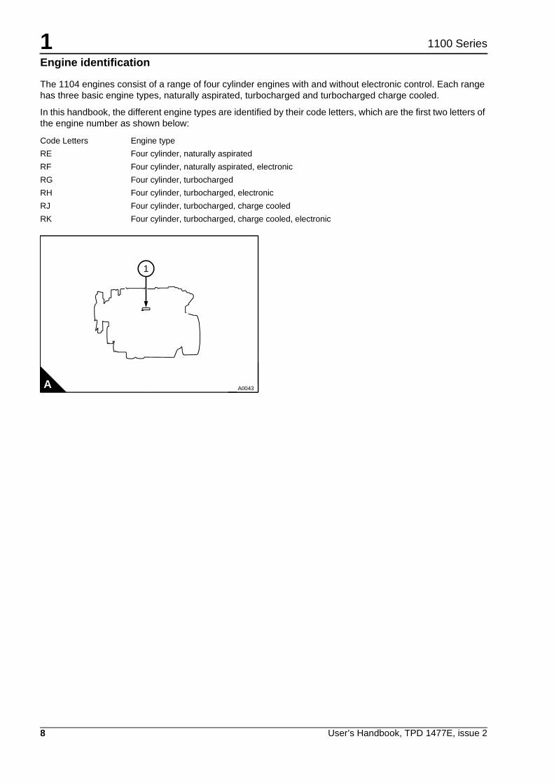
In this handbook, the different engine types are identified by their code letters, which are the first two letters ofthe engine number as shown below:
Code Letters Engine type
RE Four cylinder, naturally aspirated
RF Four cylinder, naturally aspirated, electronic
RG Four cylinder, turbocharged
RH Four cylinder, turbocharged, electronic
RJ Four cylinder, turbocharged, charge cooled
RK Four cylinder, turbocharged, charge cooled, electronic
1
A A0043

1
User’s Handbook, TPD 1477E, issue 2 9
1100 Series
Engine data
Number of cylinders. ... ... ... ... ... ... ... ... ... ... ... ... ... ... ... ... ... ... ... ... ... ... ... ... ... ... ... ... ... ... ... ... ... ... 4Cylinder arrangement .. ... ... ... ... ... ... ... ... ... ... ... ... ... ... ... ... ... ... ... ... ... ... ... ... ... ... ... ... ... ... ... .In lineCycle ... ... ... ... ... ... ... ... ... ... ... ... ... ... ... ... ... ... ... ... ... ... ... ... ... ... ... ... ... ... ... ... ... ... ... ... Four strokeDirection of rotation . ... ... ... ... ... ... ... ... ... ... ... ... ... ... ... ... ... ... ... ... ... ... ... ... ... Clockwise from the front
Induction system:
- RE, RF... ... ... ... ... ... ... ... ... ... ... ... ... ... ... ... ... ... ... ... ... ... ... ... ... ... ... ... ... ... ... ... Naturally aspirated- RG, RH.. ... ... ... ... ... ... ... ... ... ... ... ... ... ... ... ... ... ... ... ... ... ... ... ... ... ... ... ... ... ... ... ... ... Turbocharged- RJ, RK ... ... ... ... ... ... ... ... ... ... ... ... ... ... ... ... ... ... ... ... ... ... ... ... ... ... ... ... Turbocharged, charge cooledCombustion system . ... ... ... ... ... ... ... ... ... ... ... ... ... ... ... ... ... ... ... ... ... ... ... ... ... ... ... ... ...Direct injectionNominal bore ... ... ... ... ... ... ... ... ... ... ... ... ... ... ... ... ... ... ... ... ... ... ... ... ... ... ... ... ... ... . 105 mm (4.134 in)Stroke .. ... ... ... ... ... ... ... ... ... ... ... ... ... ... ... ... ... ... ... ... ... ... ... ... ... ... ... ... ... ... ... ... ... 127 mm (5.00 in)
Compression ratios:
- Naturally aspirated ... ... ... ... ... ... ... ... ... ... ... ... ... ... ... ... ... ... ... ... ... ... ... ... ... ... ... ... ... ... ... ... 19.3:1- Turbocharged ... ... ... ... ... ... ... ... ... ... ... ... ... ... ... ... ... ... ... ... ... ... ... ... ... ... ... ... ... ... ... ... ... ... 18.2:1
Cubic capacity . ... ... ... ... ... ... ... ... ... ... ... ... ... ... ... ... ... ... ... ... ... ... ... ... ... ... ... ... ... ..4,4 litres (268 in3)Firing order .. ... ... ... ... ... ... ... ... ... ... ... ... ... ... ... ... ... ... ... ... ... ... ... ... ... ... ... ... ... ... ... ... ... ... 1, 3, 4, 2
Valve tip clearances cold:
- Inlet ... ... ... ... ... ... ... ... ... ... ... ... ... ... ... ... ... ... ... ... ... ... ... ... ... ... ... ... ... ... ... ... ... 0,20 mm (0.008 in)- Exhaust . ... ... ... ... ... ... ... ... ... ... ... ... ... ... ... ... ... ... ... ... ... ... ... ... ... ... ... ... ... ... ... 0,45 mm (0.018 in)
Lubricating oil pressure (1) ... ... ... ... ... ... ... ... ... ... ... ... ... ... ... ... ... ... ... ... ... .300 kpa (43 lbf/in) 3.0 kg/cm(1) Minimum pressure at maximum engine speed and normal engine temperature

This page is intentionally blank

User’s Handbook, TPD 1477E, issue 2 11
21100 Series
Engine views 2
Introduction
Perkins engines are built for specific applications and the views that follow do not necessarily match yourengine’s specification.
Location of engine parts
Front and left side of the RE engine
1 Filler cap for the lubricating oil
2 Electric fuel lift pump
3 Fuel filter
4 Fuel injection pump
5 Starter motor
6 Lubricating oil dipstick
7 Lubricating oil sump
8 Drain plug for the lubricating oil
9 Crankshaft pulley
10 Fan
11 Coolant pump
12 Sender unit for the Start and advance (KSB)
13 Thermostat housing
14 Front lift bracket
A R1277
14
13
12
11
10
9
1
2
5
6
7
8
3
4

2
12 User’s Handbook, TPD 1477E, issue 2
1100 Series
Front and right side of the RK engine
1 Coolant tempture sensor
2 Fan pulley
3 Alternator
4 Drive belts
5 Turbocharger lubricating oil pipe
6 Turbocharger
7 Exhaust manifold
8 Rocker cover
A R1278
2
1
3
5
4
8
7
6

2
User’s Handbook, TPD 1477E, issue 2 13
1100 Series
Rear and left side of the RK engine
9 Intake manifold temperature sensor
10 Intake manifold pressure sensor
11 Lubricating oil cooler
12 Engine speed and timing sensor
13 Lubricating oil filter
14 Engine oil pressure sensor
15 Machine interface connector (MIC)
16 Engine control module (ECM)
A R1279/4
16
15
14
13
9
10
11
12

2
14 User’s Handbook, TPD 1477E, issue 2
1100 Series
Sensor positions
Rear and left side of the RH engine
1 Intake manifold temperature sensor 3 Oil pressure sensor
2 Speed and timing sensor 4 Intake manifold pressure sensor
1
2
3
A R1279/3
4
B

2
User’s Handbook, TPD 1477E, issue 2 15
1100 Series
Front and right side of the RH engine
5 Coolant temperature sensor
A R1278/2
5

This page is intentionally blank

User’s Handbook, TPD 1477E, issue 2 17
31100 Series
Operation instructions 3
How to start the engine
Warning! Ether type fuels must not be used in the 1100 series four cylinder engine.
The 1104 electronic engines are fitted with an automatic glow plug cold starting system. The 1104 mechanicalengines have a manual system. Refer to the equipment manual for the type of starting aid fitted.
Several factors affect engine start, for example:
! The power of the batteries
! The performance of the starter motor
! The viscosity of the lubricating oil
! The installation of a cold starting system.
The engine is fitted with a cold starting device for normal conditions of operation. Diesel engines need an extracold starting aid if they are to start in very cold conditions. Normally, your vehicle or your machine will be fittedwith the correct equipment for your region of operation.
Glow Plug starting aid
An electrically operated device fitted to each cylinder that heats the intake air.
Continued

3
18 User’s Handbook, TPD 1477E, issue 2
1100 Series
How to start a cold electronic engine
Cautions:! Ensure that the engine and starter motor are stationary before the starter motor is engaged.
! For the electronic engine the engine speed on start up is controlled by the ECM. The speed control shouldnot be adjusted.
1 Turn the start key to the “R” position (A) and keep it there for 20 seconds.
2 Turn the start key to the “S” position (A) to engage the starter motor. Allow the start key to return to the “R”position, when the engine starts.
3 If the engine does not start in 30 seconds, turn the start key to the “0” position (A). Wait for 90 seconds. Thenturn the start key to the “R” position (A) and keep it there for 20 seconds. Then engage the starter motor for amaximum period of 30 seconds.
How to start a warm electronic engine
1 Turn the start key to the “S” position (A) to engage starter motor for a maximum period of 30 seconds.
2 Allow the start key to return to the “R” position (A) as soon as the engine starts.
3 If the engine does not start in 30 seconds, turn the start key to the “0” position (A) and wait 90 seconds. Thenengage the starter motor again for a maximum period of 30 seconds.
How to start a cold mechanical engine with the glow plug starting aid
1 Turn the start key to the “H” position (B) and keep it there for 20 seconds.
2 Adjust the engine speed control to the maximum speed position.
3 Turn the start key to the “HS” position (B) to engage the starter motor. Allow the start key to return to the “R”position (B) when the engine starts. Then adjust the engine speed control to give an even idle speed.
4 If the engine does not start in 30 seconds, turn the start key to the “0” position (B) and wait 90 seconds. Turnthe start key to the “H” position (B) and hold it there for 20 seconds. Then engage the starter motor again, fora maximum period of 30 seconds.
How to start a warm mechanical engine
1 Adjust the engine speed control to one quarter of maximum speed.
2 Turn the start key to the "HS" position (B) to engage the starter motor.
3 If the engine does not start in 30 seconds, turn the start key to the “0” position (B) and wait 90 seconds. Thenengage the starter motor again for a maximum period of 30 seconds.
A
0 R
S
B
0 R
H
HS
3
User’s Handbook, TPD 1477E, issue 2 19
1100 Series
How to stop the engine
Caution: It is recommended that a turbocharged engine is run at approximately 1000 rev/min at a reducedload for 2-3 minutes before it is shut down. This will allow the turbocharger to cool.
Turn the engine start key to the "O" position (A or B on page 18).
Adjustment of the engine speed range
Caution: The engine speed settings should not be changed by the engine operator, because this can causethe exhaust emissions to become excessive and may also damage the engine or transmission.
Note: For electronic engines the speed range is controlled by the ECM.
Running-in
Cautions:! Do not operate the engine at high speeds without a load.
! Do not overload the engine.
A gradual running-in of a new engine or an exchange engine is not necessary. Prolonged operation at lightloads during the early life of the engine can cause lubricating oil to enter the exhaust system. Maximum loadcan be applied to a new engine as soon as the engine is put into service and when the coolant temperaturehas reached a minimum of 60 °C (140 °F).
The engine will benefit if the load is applied as soon as possible after the engine is put into service.
Turbocharged engines
Because of the power characteristics of the turbocharged engines, when fitted in vehicles, it is necessary tomaintain a high engine speed when you need full load. To ensure that the engine is not overloaded at lowengine speeds engage a lower gear.
Angle of tilt
Warning! Do not operate the engine at an angle of tilt greater than the limit approved for the engine. Refer tothe equipment handbook for details.

This page is intentionally blank

User’s Handbook, TPD 1477E, issue 2 21
41100 Series
Preventive maintenance 4
Preventive maintenance periods
Use the procedures in this chapter to maintain your engine in accordance with the preventive maintenanceschedule.
Check the periods given by the manufacturer of the equipment in which the engine is installed.
It is good preventive maintenance to check for leakage and loose fasteners at each service.
These maintenance periods apply only to engines that are operated with fuel, lubricating oil and coolant thatconform to the specifications given in this handbook.

4
22 User’s Handbook, TPD 1477E, issue 2
1100 Series
Preventive maintenance schedules
The schedules which follow must be applied at the intervals (hours or months) which ever occur first.
(1) By a person who has had the correct training.(2) The oil service interval will change with the amount of sulphur in the fuel see, "Fuel specification" on page 39. The interval to changethe canister or element of the lubricating oil filter is not affected.(3) See, "Lubricating oil specification" on page 40.(4) Renew the antifreeze every 2 years. If a coolant inhibitor is used instead of antifreeze, it should be renewed every 6 months. Ifcombustion gases are released into the coolant circuit, the coolant must be renewed.(5) For turbocharged and charge cooled engines only see,"How to renew the closed crankcase breather filter element" on page 33.(6) Engines with high load factor or high oil temperature will require a 250 hour or 12 months service period, whichever occurs first.This would normally be determined between the customer and the Perkins applications engineer, but would typically be anything above75% load factor (average) or 125 °C oil temperature (more than 1 hour in 12). Load factors should be expressed in actual f uel useddivided by fuel load rated speed used. For further information and advice, contact Perkins applications.(7) Check, and if necessary renew the air filter element.
A Every day or every 8 hours C Every 1000 hours
B Every 500 hours or 12 months D Every 8000 hours
A B C D Operation
! Check the amount of coolant in the header tank
! Check the engine for leakage of oil and coolant
! Check the specific gravity of the coolant (1) (4)
! Check the tension and condition of the drive belt(s)
! Check for water in the pre-filter bowl (or earlier if your fuel supply is contaminated)
! Renew the element(s) of the fuel filter(s)
! Check the amount of lubricating oil in the sump
! Check the lubricating oil pressure at the gauge
! Renew the engine lubricating oil (2) (3) (6)
! Renew the closed crankcase breather element (5)
! Renew the closed breather assembly
! Renew the canister or element of the lubricating oil filter (2) (3) (6)
Empty the dust bowl of the air filter:
! - Normal conditions
! - In extremely dusty conditions (7)
! Renew the air filter element
! Check all hoses and connections
! Check all electrical cables and connections
! Check the valve tip clearances of the engine and adjust, if necessary (1)

4
User’s Handbook, TPD 1477E, issue 2 23
1100 Series
How to drain the cooling system
Warning! Do not drain the coolant while the engine is still hot and the system is under pressure becausedangerous hot coolant can be discharged.
Caution: To prevent frost damage, ensure that all of the coolant is removed from the engine. This is importantif the system is drained after it has been flushed with water, or if an antifreeze solution which is too weak toprotect the system from frost has been used.
1 Ensure that the machine is on level ground.
2 Remove the filler cap of the coolant system.
3 Open the tap or remove the drain plug at the bottom of the radiator in order to drain the radiator. If the radiatordoes not have a tap or drain plug, disconnect the hose at the bottom of the radiator.
4 Remove the drain plug (A1) from the side of the cylinder block in order to drain the engine. Ensure that thedrain hole is not restricted.
5 Flush the coolant system with clean water.
6 Fit the drain plug (A1) and tighten to 40 Nm (29,5 lbf ft) 4,1kgf m.
7 Fit the filler cap and close the radiator tap, or fit the bottom hose.
How to fill the cooling system
Warning! Refer to your equipment supplier's handbook for the application to fill the cooling system. If coolantis to be added to the system during service, allow the engine to cool before the coolant is added. Do not addcoolant while the engine is still hot and the system is under pressure because dangerous hot coolant can bedischarged.
Caution: If coolant is added to the circuit during service, it must consist of the same original mixture as usedto fill the system. For details of the correct coolant to be used in the system, see "Coolant specification" onpage 40.
1 Ensure that the top and bottom hose connections are fitted correctly.
2 Check that the drain plug (A1) on the side of the cylinder block is fitted and tighten to 40 Nm (29,5 lbf ft)4,1kgf m. Ensure that the radiator tap is closed, if one is fitted.
3 Remove filler cap. Fill the cooling system with coolant of the correct specification, see "Coolant specification"on page 40.
4 Continue to slowly fill the cooling system to the correct level, refer to the user’s handbook for the application.
5 Fit the filler cap, run the engine to normal operating temperature. Stop the engine. When the engine hascooled, check the coolant level. If necessary, fill again to the correct level.
R1188/1A
1

4
24 User’s Handbook, TPD 1477E, issue 2
1100 Series
How to check the specific gravity of the coolant
For mixtures which contain inhibited ethylene glycol:
1 Ensure that the machine is on level ground.
2 Operate the engine until it is warm enough to open the thermostat. Continue to run the engine until thecoolant has circulated the cooling system.
3 Stop the engine.
4 Allow the engine to cool until the temperature of the coolant is below 60 °C (140 °F).
Warning! Do not drain the coolant while the engine is still hot and the system is under pressure becausedangerous hot coolant can be discharged.
5 Remove the filler cap of the cooling system.
6 Drain some coolant from the cooling system into a suitable container.
7 Use a special coolant hydrometer that will check the temperature and the specific gravity of the coolant,follow the manufacturer's instructions.
Note: If a special coolant hydrometer is not available, put a hydrometer and a separate thermometer into theantifreeze mixture and check the readings on both instruments. Compare the readings with the chart (A).
8 Adjust the strength of the mixture as necessary.
Note: If it is necessary to fill or replenish the coolant system in service, mix the coolant to the correct strengthbefore it is added to the coolant system. Perkins POWERPART antifreeze with a concentration of 50% will giveprotection against frost to a temperature of -35 °C (-31 °F). It will also give protection against corrosion. Thisis especially important when there are aluminium components in the coolant circuit.
Specific gravity chart
A = Percentage antifreeze by volume
B = Mixture temperature in °F
C = Specific gravity
D = Mixture temperature in °C
A
140
122
104
86
68
50
60
50
40
30
20
10
01.04 1.05 1.06
504540 55 60A
C
BD
1.07 1.08 1.09 1.10 1.11
4
User’s Handbook, TPD 1477E, issue 2 25
1100 Series
How to check the drive belt(s)
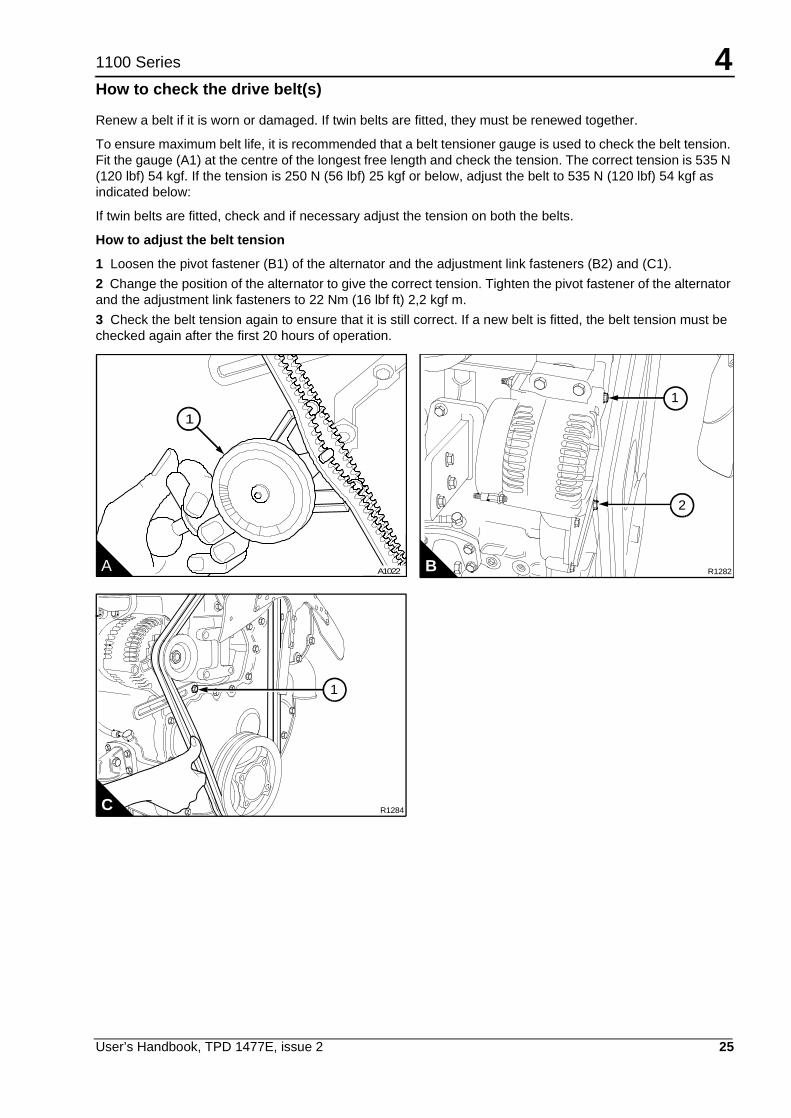
Renew a belt if it is worn or damaged. If twin belts are fitted, they must be renewed together.
To ensure maximum belt life, it is recommended that a belt tensioner gauge is used to check the belt tension.Fit the gauge (A1) at the centre of the longest free length and check the tension. The correct tension is 535 N(120 lbf) 54 kgf. If the tension is 250 N (56 lbf) 25 kgf or below, adjust the belt to 535 N (120 lbf) 54 kgf asindicated below:
If twin belts are fitted, check and if necessary adjust the tension on both the belts.
How to adjust the belt tension
1 Loosen the pivot fastener (B1) of the alternator and the adjustment link fasteners (B2) and (C1).
2 Change the position of the alternator to give the correct tension. Tighten the pivot fastener of the alternatorand the adjustment link fasteners to 22 Nm (16 lbf ft) 2,2 kgf m.
3 Check the belt tension again to ensure that it is still correct. If a new belt is fitted, the belt tension must bechecked again after the first 20 hours of operation.
A A1022
1
R1282B
2
1
R1284C
1

4
26 User’s Handbook, TPD 1477E, issue 2
1100 Series
Fuel pre-filter
A pre-filter, if fitted, is installed between the fuel tank and the engine. Check the pre-filter bowl for water atregular intervals and drain as necessary, see "Preventive maintenance schedules" on page 22.
How to renew the fuel filter element
Warnings!! The combustible material of some components of the engine (for example certain seals) can become
extremely dangerous if it is burned. Never allow this burnt material to come into contact with the skin or withthe eyes.
! Discard the used element and fuel oil in a safe place and in accordance with local regulations.
! Ensure that the starter switch is in the off position before servicing or repairs are made to the fuel system,because fuel will be released if the lift pump has power.
! If the fuel level in the tank is higher than the fuel lift pump, all the fuel line valves must be closed beforemaintenance or repairs are made to the fuel system, if this is not done, the fuel system will drain.
Cautions:! It is important that only genuine Perkins parts are used. The use of an element that is not a genuine Perkins
part may damage the fuel injection pump and the warranty.
! The pre-filter canister and main filter elements must be renewed at the same time.
! Do not allow dirt to enter the fuel system. Before a connection is disconnected, clean thoroughly the areaaround the connection. After a component has been disconnected, fit a suitable cover to all openconnections.
1 Place a suitable container below the fuel filter assembly to retain spilt fuel oil.
2 Thoroughly clean the outside surfaces of the fuel filter assembly. Open the drain tap (A1) at the bottom ofthe filter casing to drain the fuel from the filter.
3 Loosen the filter casing. Remove the casing and element from the fuel filter head.
Continued

4
User’s Handbook, TPD 1477E, issue 2 27
1100 Series
4 Remove the filter element from the casing. Press down on the filter element (B1), against the springpressure, and rotate it to the left to release it from the filter casing (B4).
5 Put the new filter element inside the casing and press it down against the spring pressure, rotate it to theright to lock it into the casing.
6 Fit a new seal (B3) to the casing and lightly lubricate the seal face with clean fuel oil.
7 Check that the thread (B2) on the inside of the element is not damaged.
8 Fit the filter assembly to the fuel filter head and tighten by hand until it contacts the filter head. Tighten theassembly a further 1/4 of a turn by hand. Do not use a strap wrench.
9 Close the drain tap (A1) and remove the container.
10 Before the starter motor is engaged, operate the lift pump for one minute to eliminate air from the filter.
11 Start the engine and check for leaks.
R1185/1A1
R1189/3B
4
21
3
4
28 User’s Handbook, TPD 1477E, issue 2
1100 Series
How to eliminate air from the fuel system
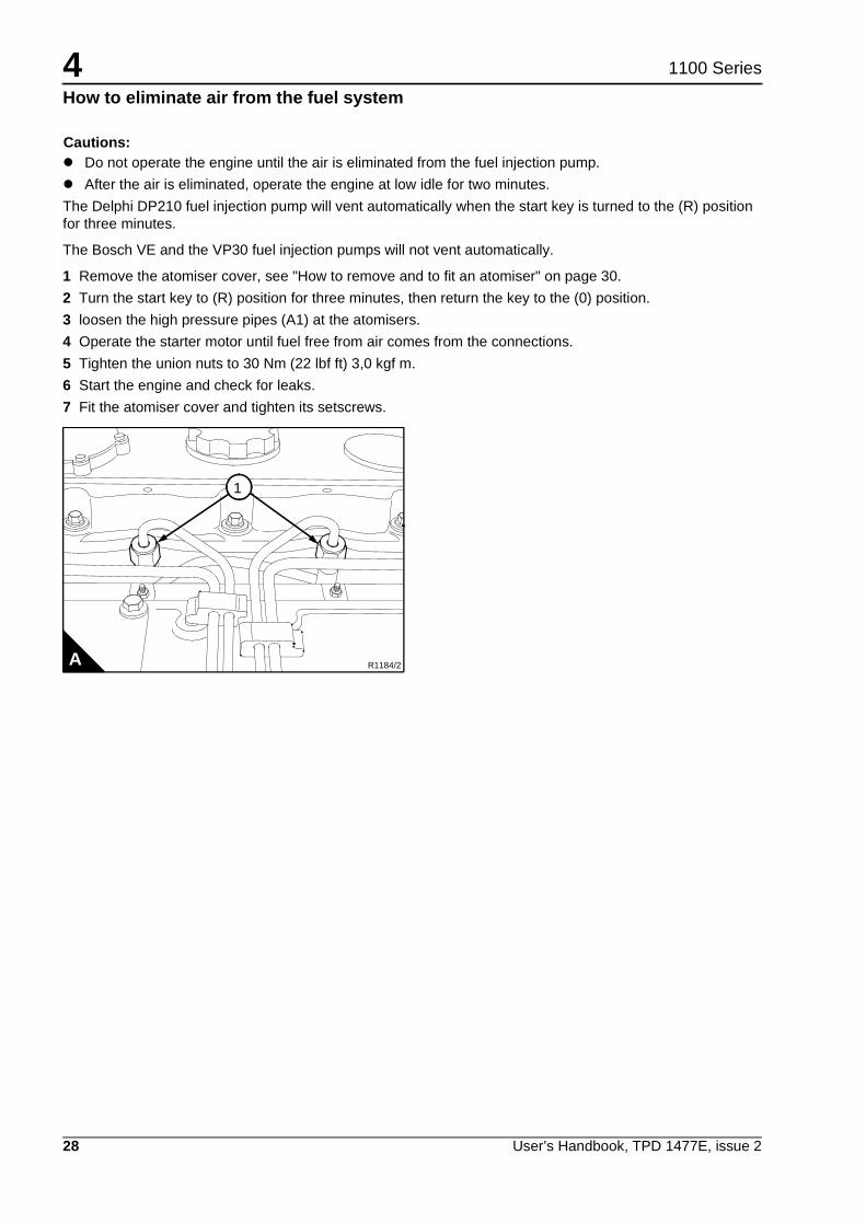
Cautions:! Do not operate the engine until the air is eliminated from the fuel injection pump.
! After the air is eliminated, operate the engine at low idle for two minutes.
The Delphi DP210 fuel injection pump will vent automatically when the start key is turned to the (R) positionfor three minutes.
The Bosch VE and the VP30 fuel injection pumps will not vent automatically.
1 Remove the atomiser cover, see "How to remove and to fit an atomiser" on page 30.
2 Turn the start key to (R) position for three minutes, then return the key to the (0) position.
3 loosen the high pressure pipes (A1) at the atomisers.
4 Operate the starter motor until fuel free from air comes from the connections.
5 Tighten the union nuts to 30 Nm (22 lbf ft) 3,0 kgf m.
6 Start the engine and check for leaks.
7 Fit the atomiser cover and tighten its setscrews.
R1184/2A
1
4
User’s Handbook, TPD 1477E, issue 2 29
1100 Series
Atomiser faults
Caution: A faulty atomiser must be renewed by a person who has had the correct training.
Regular maintenance of the atomisers is not necessary. The atomiser nozzles should be renewed and notcleaned, and renewed only if an atomiser fault occurs. Some of the problems that may indicate that newnozzles are needed are listed below:
Engine will not start or is difficult to start
Not enough power
Engine misfires or runs erratically
High fuel consumption
Black exhaust smoke
Engine knocks or vibrates excessively
Excessive engine temperature.
Warnings!! If your skin comes into contact with high-pressure fuel, obtain medical assistance immediately.
! Keep away from moving parts during engine operation. Some moving parts cannot be seen clearly whilethe engine runs.
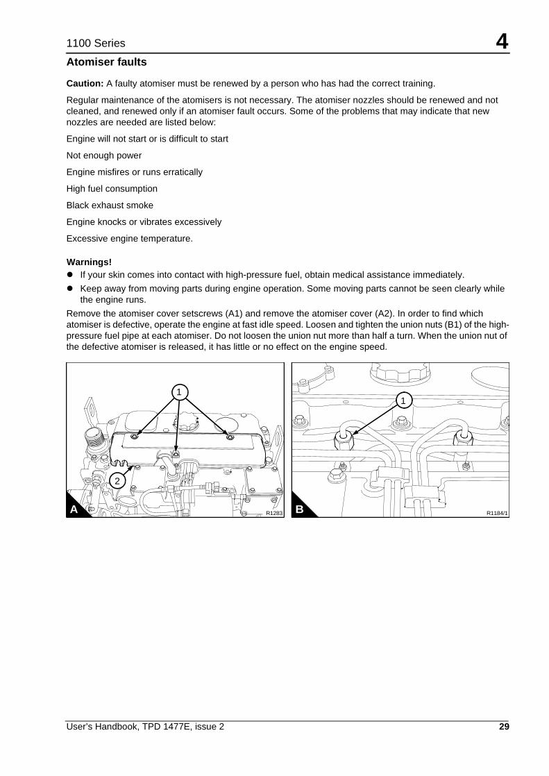
Remove the atomiser cover setscrews (A1) and remove the atomiser cover (A2). In order to find whichatomiser is defective, operate the engine at fast idle speed. Loosen and tighten the union nuts (B1) of the high-pressure fuel pipe at each atomiser. Do not loosen the union nut more than half a turn. When the union nut ofthe defective atomiser is released, it has little or no effect on the engine speed.
R1184/1B
1
R1283A
1
2

4
30 User’s Handbook, TPD 1477E, issue 2
1100 Series
How to remove and to fit an atomiser
How to remove
Warning! The combustible material of some components of the engine (for example certain seals) canbecome extremely dangerous if it is burned. Never allow this burnt material to come into contact with the skinor with the eyes.
Cautions:! Atomisers must be removed and fitted by a person with the correct training.
! Do not allow dirt to enter the fuel system. Before a connection is disconnected, clean thoroughly the areaaround the connection. After a component has been disconnected, fit a suitable cover to all openconnections.
1 If necessary remove the crossover pipe from the turbocharger to the intake manifold.
Note: There are different types of breather pipe for naturally aspirated engine and turbocharged engine. Anoutlet hose may need to be removed from the breather pipe on the turbocharged engines.
2 Release the atomiser cover setscrews (A1) and remove the atomiser cover (A4).
3 If necessary on a turbocharged engine release the breather hose clip and remove the hose.
4 Release the fastener (A2) and remove the breather pipe (A3).
Continued
R1283/1A
4
2
1
3
4
User’s Handbook, TPD 1477E, issue 2 31
1100 Series
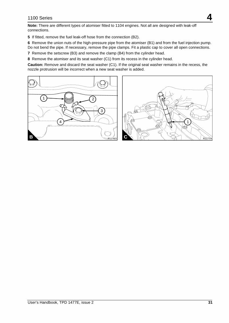
Note: There are different types of atomiser fitted to 1104 engines. Not all are designed with leak-offconnections.
5 If fitted, remove the fuel leak-off hose from the connection (B2).
6 Remove the union nuts of the high-pressure pipe from the atomiser (B1) and from the fuel injection pump.Do not bend the pipe. If necessary, remove the pipe clamps. Fit a plastic cap to cover all open connections.
7 Remove the setscrew (B3) and remove the clamp (B4) from the cylinder head.
8 Remove the atomiser and its seat washer (C1) from its recess in the cylinder head.
Caution: Remove and discard the seat washer (C1). If the original seat washer remains in the recess, thenozzle protrusion will be incorrect when a new seat washer is added.
R1177/4C
1
R1178/3B
2
3
4
1
4
32 User’s Handbook, TPD 1477E, issue 2
1100 Series
How to fit
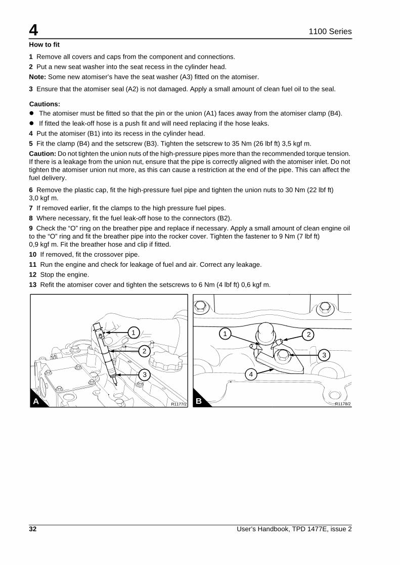
1 Remove all covers and caps from the component and connections.
2 Put a new seat washer into the seat recess in the cylinder head.
Note: Some new atomiser’s have the seat washer (A3) fitted on the atomiser.
3 Ensure that the atomiser seal (A2) is not damaged. Apply a small amount of clean fuel oil to the seal.
Cautions:! The atomiser must be fitted so that the pin or the union (A1) faces away from the atomiser clamp (B4).
! If fitted the leak-off hose is a push fit and will need replacing if the hose leaks.
4 Put the atomiser (B1) into its recess in the cylinder head.
5 Fit the clamp (B4) and the setscrew (B3). Tighten the setscrew to 35 Nm (26 lbf ft) 3,5 kgf m.
Caution: Do not tighten the union nuts of the high-pressure pipes more than the recommended torque tension.If there is a leakage from the union nut, ensure that the pipe is correctly aligned with the atomiser inlet. Do nottighten the atomiser union nut more, as this can cause a restriction at the end of the pipe. This can affect thefuel delivery.
6 Remove the plastic cap, fit the high-pressure fuel pipe and tighten the union nuts to 30 Nm (22 lbf ft)3,0 kgf m.
7 If removed earlier, fit the clamps to the high pressure fuel pipes.
8 Where necessary, fit the fuel leak-off hose to the connectors (B2).
9 Check the “O” ring on the breather pipe and replace if necessary. Apply a small amount of clean engine oilto the “O” ring and fit the breather pipe into the rocker cover. Tighten the fastener to 9 Nm (7 lbf ft)0,9 kgf m. Fit the breather hose and clip if fitted.
10 If removed, fit the crossover pipe.
11 Run the engine and check for leakage of fuel and air. Correct any leakage.
12 Stop the engine.
13 Refit the atomiser cover and tighten the setscrews to 6 Nm (4 lbf ft) 0,6 kgf m.
R1177/2A
2
3
1
R1178/2B
21
3
4

4
User’s Handbook, TPD 1477E, issue 2 33
1100 Series
How to renew the closed crankcase breather filter element
Note: For details on how to change the closed crankcase breather element, contact Perkins applications foradvice.
How to renew the engine lubricating oil
Warnings!! Discard the used lubricating oil in a safe place and in accordance with local regulations.
! Do not exceed the correct level of lubricating oil in the sump. If there is too much lubricating oil, the excessmust be drained to the correct level. An excess of lubricating oil could enter the breather valve. This couldcause the engine speed to increase rapidly without control.
Caution: Ensure that the machine is on a level surface to ensure an accurate reading on the dipstick.
1 Operate the engine until it is warm. Stop the engine.
2 Put a suitable container below the lubricating oil sump.
3 Remove the sump drain plug (A1) and its “O” ring and drain the lubricating oil from the sump into thecontainer.
4 Ensure that the “O” ring is not damaged. Fit the drain plug and its “O” ring and tighten the plug to 34 Nm(25 lbf ft) 3,5 kgf m.
5 Fill the sump to the mark (A2) on the dipstick with new and clean lubricating oil of an approved grade, see"Lubricating oil specification" on page 40.
6 Remove the container and discard old lubricating oil.
R1187/2A
1
2

4
34 User’s Handbook, TPD 1477E, issue 2
1100 Series
How to renew the canister type oil filter
Warning! Discard the used canister, and lubricating oil in a safe place and in accordance with localregulations.
Cautions:! Ensure that the machine is on a level surface to ensure an accurate reading on the dipstick
! It is important that only genuine Perkins parts are used. The use of an canister that is not a genuine Perkinspart may damage the engine and the warranty.
Note: The canister contains a valve and a special tube to ensure that lubricating oil does not drain from thefilter, when the lubricating oil is changed.
1 Put a suitable container below the lubricating oil filter.
2 Remove the filter canister with a strap wrench. Ensure that the adaptor is secure in the filter head. Discardthe canister.
3 Clean the filter head.
Note: It is normally good procedure to fill the oil filter canister with clean engine lubricating oil. However thismay not be possible on certain applications.
4 Lubricate the top of the canister seal (A1) with clean engine lubricating oil.
5 Fit the new canister and tighten it by hand only. Do not use a strap wrench.
6 Remove the container and discard the old lubricating oil.
7 Operate the engine and check for leakage from the filter. When the engine has cooled, check the oil levelon the dipstick and add more oil into the sump, if necessary.
R1186/1A
1

4
User’s Handbook, TPD 1477E, issue 2 35
1100 Series
How to renew the element type oil filter
Warning! Discard the used element and lubricating oil in a safe place and in accordance with local regulations.
Cautions:! Ensure that the machine is on a level surface to ensure an accurate reading on the dipstick.
! It is important that only genuine Perkins parts are used. The use of an element that is not a genuine Perkinspart may damage the engine and the warranty.
1 Put a suitable container below the lubricating oil filter.
2 Remove the plug together with the seal (A2) and drain the lubricating oil.
3 Fit a 1/2” square drive ratchet into the recess (A1) and remove the filter casing (A3). Discard the old filterelement.
4 Clean the filter casing and replace the seal (B2).
5 Fit the new filter element (B1) into the casing and rotate element to locate it into position.
Note: It is normally good procedure to fill the oil filter casing with clean engine lubricating oil. However, thismay not be possible on certain applications.
6 Lubricate the seal (B2) with clean engine lubricating oil. Fit the casing (A3) into the filter head (A4).
7 Tighten the casing (A3) to 25 Nm (18 lbf ft) 2,5 kgf m.
8 Fit a new seal to the drain plug and tighten the drain plug to 12 Nm (9 lbf ft) 1,2 kgf m.
9 Remove the container and discard the old lubricating oil.
10 Operate the engine and check for leakage from the filter. When the engine has cooled, check the oil levelon the dipstick and add more lubricating oil into the sump, if necessary.
R1340/1B
2
1
R1339/2A
3
2
4
1

4
36 User’s Handbook, TPD 1477E, issue 2
1100 Series
Air filter
Caution: Do not operate the engine if there is a blockage in the air filter or the induction hose. This can causelubricating oil to enter the cylinders through the breather valve.
Environmental conditions have an important effect on the frequency at which the air filter needs service.
Certain air filters have a separate dust bowl (A1) which must be cleaned at intervals. The amount of dust in thebowl shows if it has been removed at the correct time for the conditions of operation. Do not let dust completelyfill the bowl, because this will reduce the life of the filter element (A2).
Certain air filters have automatic dust valves (B1) through which dust is expelled from the filter. The rubberdust valve must be kept clean. Ensure that the sides of the valves close completely together and that they canseparate freely.
If a restriction indicator (C) is fitted, it will indicate precisely when the air filter element needs service. Thisprevents the premature removal of the filter element which causes extra cost or late removal of the elementwhich can cause loss of engine power. The filter element must be cleaned or renewed according to themanufacturers recommendations.
1
B A1040
A
2
1

4
User’s Handbook, TPD 1477E, issue 2 37
1100 Series
Restriction indicator
The restriction indicator is fitted on the air filter outlet or between the air filter and the induction manifold.
When the red warning indicator (A1) is seen through the clear panel (A2) after the engine has stopped, the airfilter element must be removed for service.
After a clean element has been fitted, press the rubber bottom (A3) or the button (A4) of the restriction indicatorto reset the red warning indicator.
2
3
1
12
4
A

4
38 User’s Handbook, TPD 1477E, issue 2
1100 Series
How to check the valve tip clearances
The valve tip clearances are checked between the top of the valve stem and the rocker lever (A), with theengine cold. The correct clearance for inlet valves is 0,20 mm (0.008 in) and 0,45 mm (0.018 in) for exhaustvalves. The valve positions are shown at (B).
The sequence of valves from number 1 cylinder is shown in the table below.
Note: Number 1 cylinder is the furthest cylinder from the flywheel end of the engine.
1 Rotate the crankshaft in the normal direction of rotation until the inlet valve (B7) of number 4 cylinder hasjust opened and the exhaust valve (B8) of the same cylinder has not closed completely. Check the clearancesof the valves (B1 and B2) of number 1 cylinder and adjust them, if necessary.
2 Set the valves (B3 and B4) of number 2 cylinder as indicated above for number 4 cylinder. Then check /adjust the clearances of the valves (B5 and B6) of number 3 cylinder.
3 Set the valves (B1 and B2) of number 1 cylinder. Then check / adjust the clearances of the valves (B7 andB8) of number 4 cylinder.
4 Set the valves (B5 and B6) of number 3 cylinder. Then check / adjust the clearances of the valves (B3 andB4) of number 2 cylinder.
Cylinderandvalve number
1 2 3 4
1 2 3 4 5 6 7 8
ValveI = InletE = Exhaust
I E I E I E I E
R1181B
1 2 3 4 5 6 7 8
A R1180/1

User’s Handbook, TPD 1477E, issue 2 39
51100 Series
Engine fluids 5
Fuel specification
To get the correct power and performance from your engine, use good quality fuel.
Recommended fuel specification
! EN590 Diesel Fuel Types - Auto/C0/C1/C2/C3/C4
! BS2869 Class A2
! ASTM D975-91 Class 2-2DA, US DF1, US DF2, US DFA
! JIS K2204 (1992) Grades 1, 2 ,3, and Special Grade 3.
Note: Where low sulphur / low aromatic fuels are used it is important that lubricity additives are used.
Acceptable fuel specification
Caution: The fuel specification below is acceptable, however this fuel may reduce the life of the fuel injectionequipment. The use of this fuel may also effect the engine performance.
! ASTM D975-91 Class 1-1DA
! JP7, MIL T38219 XF63
! NATO F63.
Low sulphur fuel
Low temperature fuels
Special winter fuels may be available for engine operation at temperatures below 0 °C. T hese fuels have alower viscosity and also limit the wax formation in the fuel at low temperatures. If wax formation occurs, thiscould stop the fuel flow through the filter.
Aviation kerosene fuels
Note: Aviation kerosine fuels have not been approved for the 1100 series engine.
Percentage of sulphur inthe fuel (%)
Oil change interval
< 0.5 Normal
0.5 to 1.0 0.75 of normal
> 1.0 0.50 of normal
5
40 User’s Handbook, TPD 1477E, issue 2
1100 Series
Lubricating oil specification
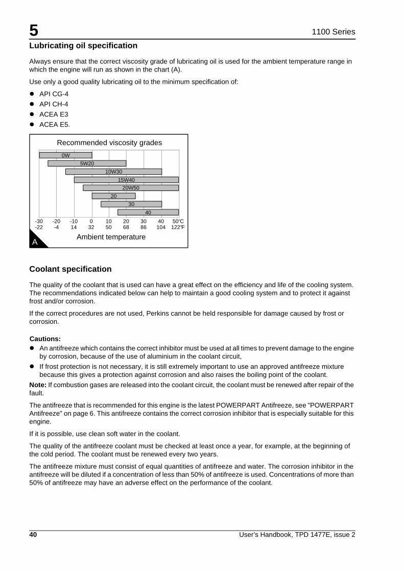
Always ensure that the correct viscosity grade of lubricating oil is used for the ambient temperature range inwhich the engine will run as shown in the chart (A).
Use only a good quality lubricating oil to the minimum specification of:
! API CG-4
! API CH-4
! ACEA E3
! ACEA E5.
Coolant specification
The quality of the coolant that is used can have a great effect on the efficiency and life of the cooling system.The recommendations indicated below can help to maintain a good cooling system and to protect it againstfrost and/or corrosion.
If the correct procedures are not used, Perkins cannot be held responsible for damage caused by frost orcorrosion.
Cautions:! An antifreeze which contains the correct inhibitor must be used at all times to prevent damage to the engine
by corrosion, because of the use of aluminium in the coolant circuit,
! If frost protection is not necessary, it is still extremely important to use an approved antifreeze mixturebecause this gives a protection against corrosion and also raises the boiling point of the coolant.
Note: If combustion gases are released into the coolant circuit, the coolant must be renewed after repair of thefault.
The antifreeze that is recommended for this engine is the latest POWERPART Antifreeze, see "POWERPARTAntifreeze" on page 6. This antifreeze contains the correct corrosion inhibitor that is especially suitable for thisengine.
If it is possible, use clean soft water in the coolant.
The quality of the antifreeze coolant must be checked at least once a year, for example, at the beginning ofthe cold period. The coolant must be renewed every two years.
The antifreeze mixture must consist of equal quantities of antifreeze and water. The corrosion inhibitor in theantifreeze will be diluted if a concentration of less than 50% of antifreeze is used. Concentrations of more than50% of antifreeze may have an adverse effect on the performance of the coolant.
A
Recommended viscosity grades
0W
5W20
10W30
15W40
20W50
20
-30 -20 -10 0 10 20 30 40 50o
oC
-22 -4 14 32 50
Ambient temperature68 86 104 122 F
30
40

User’s Handbook, TPD 1477E, issue 2 41
61100 Series
Fault diagnosis 6
Continued
6
42 User’s Handbook, TPD 1477E, issue 2
1100 Series
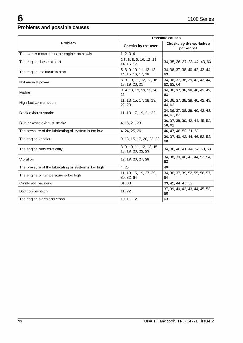
Problems and possible causes
ProblemPossible causes
Checks by the userChecks by the workshop
personnel
The starter motor turns the engine too slowly 1, 2, 3, 4
The engine does not start2,5, 6, 8, 9, 10, 12, 13,14, 15, 17
34, 35, 36, 37, 38, 42, 43, 63
The engine is difficult to start5, 8, 9, 10, 11, 12, 13,14, 15, 16, 17, 19
34, 36, 37, 38, 40, 42, 43, 44,63
Not enough power8, 9, 10, 11, 12, 13, 16,18, 19, 20, 21
34, 36, 37, 38, 39, 42, 43, 44,62, 63, 64
Misfire8, 9, 10, 12, 13, 15, 20,22
34, 36, 37, 38, 39, 40, 41, 43,63
High fuel consumption11, 13, 15, 17, 18, 19,22, 23
34, 36, 37, 38, 39, 40, 42, 43,44, 62
Black exhaust smoke 11, 13, 17, 19, 21, 2234, 36, 37, 38, 39, 40, 42, 43,44, 62, 63
Blue or white exhaust smoke 4, 15, 21, 2336, 37, 38, 39, 42, 44, 45, 52,58, 61
The pressure of the lubricating oil system is too low 4, 24, 25, 26 46, 47, 48, 50, 51, 59,
The engine knocks 9, 13, 15, 17, 20, 22, 2336, 37, 40, 42, 44, 46, 52, 53,60
The engine runs erratically8, 9, 10, 11, 12, 13, 15,16, 18, 20, 22, 23
34, 38, 40, 41, 44, 52, 60, 63
Vibration 13, 18, 20, 27, 2834, 38, 39, 40, 41, 44, 52, 54,63
The pressure of the lubricating oil system is too high 4, 25 49
The engine oil temperature is too high11, 13, 15, 19, 27, 29,30, 32, 64
34, 36, 37, 39, 52, 55, 56, 57,64
Crankcase pressure 31, 33 39, 42, 44, 45, 52,
Bad compression 11, 2237, 39, 40, 42, 43, 44, 45, 53,60
The engine starts and stops 10, 11, 12 63

6
User’s Handbook, TPD 1477E, issue 2 43
1100 Series
List of possible causes
1 Battery capacity low 43 Leakage between valves and seats
2 Bad electrical connections 44 Piston rings are not free or they are worn or broken
3 Fault in starter motor 45 Valve stems and/or guides are worn
4 Wrong grade of lubricating oil 46 Crankshaft bearings are worn or damaged
5 Starter motor turns engine too slowly 47 Lubricating oil pump is worn
6 Fuel tank empty 48 Relief valve does not close
7 Fault in stop control 49 Relief valve does not open
8 Restriction in a fuel pipe 50 Relief valve spring is broken
9 Fault in fuel lift pump 51 Fault in suction pipe of lubricating oil pump
10 Dirty fuel filter element 52 Piston is damaged
11 Restriction in air induction system 53 Piston height is incorrect
12 Air in fuel system 54 Flywheel housing or flywheel is not aligned correctly
13 Fault in atomisers or atomisers of an incorrecttype
55Fault in thermostat or thermostat is of an incorrect type
14 Cold start system used incorrectly 56 Restriction in coolant passages
15 Fault in cold start system 57 Fault in coolant pump
16 Restriction in fuel tank vent 58 Valve stem seal is damaged
17 Wrong type or grade of fuel used 59 Restriction in sump strainer
18 Restricted movement of engine speed control 60 Valve spring is broken
19 Restriction in exhaust pipe 61 Lubricating oil seal of turbocharger leaks
20 Engine temperature is too high 62 Air leak in Induction system (turbocharged engine)
21 Engine temperature is too low 63 Faulty engine management system
22 Incorrect valve tip clearances 64 Induction system leaks (turbocharged engines)
23 Too much oil or oil of the wrong type is used inwet type air cleaner, if one is fitted
24 Not enough lubricating oil in sump
25 Defective gauge
26 Dirty lubricating oil filter element
27 Fan damaged
28 Fault in engine mounting or flywheel housing
29 Too much lubricating oil in sump
30 Restriction in air or water passages of radiator
31 Restriction in breather pipe
32 Insufficient coolant in system
33 Vacuum pipe leak or fault in exhauster
34 Fault in fuel injection pump
35 Broken drive on fuel injection pump
36 Timing of fuel injection pump incorrect
37 Valve timing is incorrect
38 Bad compression
39 Cylinder head gasket leaks
40 Valves are not free
41 Wrong high-pressure pipes
42 Worn cylinder bores

This page is intentionally blank