user manual - singletact · 2017-12-29 · copyright © 2017- 2 2 22 2 i2
TRANSCRIPT

USER MANUAL
EXPERIENCE
INCREDIBLE
PERFORMANCE
V2.3

pg. 2
Copyright © 2017- www.SingleTact.com
CONTENTS
1 INTRODUCTION ............................................................................................................................................... 3
2 INTERFACE DESIGN ......................................................................................................................................... 4
2.1 Connectivity .............................................................................................................................................. 5
2.2 Analog Interface ....................................................................................................................................... 6
2.3 I2C Interface .............................................................................................................................................. 7
2.4 I2C Operations ........................................................................................................................................ 10
2.4.1 I2C Write Operation ........................................................................................................................ 10
2.4.2 I2C Read Request Operation ........................................................................................................... 11
2.4.3 I2C Read Operation.......................................................................................................................... 11
2.5 Conversion Detail ................................................................................................................................... 13
2.6 Product Categories ................................................................................................................................. 14
3 TROUBLESHOOTING SingleTact .................................................................................................................... 15
3.1 Arduino UNO not detected by PC. ......................................................................................................... 16
3.2 Invalid setting error on PC (Popup reports” Failed to set”). .................................................................. 16
3.3 No Analog output (remains at 0V). ........................................................................................................ 16
3.4 Analog output stays at 0.5V. .................................................................................................................. 16
4 EXAMPLE USE CASE ....................................................................................................................................... 17
4.1 PC and Arduino Example ........................................................................................................................ 18
4.2 Programming the Arduino UNO with SingleTact Example..................................................................... 20
4.3 Arduino Demo Outline ........................................................................................................................... 22
4.4 Example .NET API ................................................................................................................................... 26
5 Resources ...................................................................................................................................................... 27
6 Glossary ......................................................................................................................................................... 28
7 Revision History ............................................................................................................................................ 29

pg. 3
Copyright © 2017- www.SingleTact.com
1 INTRODUCTION
SingleTact is a single element tactile pressure sensor that accurately and reliably quantifies applied
force combined with a simple interface board offering a 0 to 2V analog output for immediate Data
Acquisition (DAQ) integration and an I2C based interface for integration into embedded systems.
Standard and Calibrated sensors (with matched pre-calibrated interface board) are available.
This document provides all the information necessary to interface with the SingleTact including a
sample Arduino digital interface and simple C# PC DAQ software (see EXAMPLE USE CASE)
All demo and API source code is open source and can be downloaded from: www.singletact.com.
Figure 1 SingleTact Sensor and Interface Board
Figure 2 Use Case Configurations
*1 – In addition to the data acquisition example, a .NET library is available to download for simple integration into a user’s
own software suite. See Example .NET API.
*2 – Supports over 100 SingleTact interface boards on a single I2C bus. The interface board firmware can be modified to
fit user’s specific use cases – if required please contact PPS to discuss this option.
*3 – PPS maybe able to assist with this – use the contact links at http://www.singletact.com/contact/.
SingleTact.com
1
2
3
45
6
7
8
MCU
SingleTact.com
1
2
3
45
6
7
8
MCU
Arduino and PC data acquisition evaluation software
Analogue Out. Connect to multitier, oscilloscope or data acquisition card
User reads capacitance using their own circuitry
SingleTact.com
1
2
3
45
6
7
8
MCU
UNO
SingleTact.com
I2C Digital Output. Interface to user
electronics SingleTact.com
1
2
3
45
6
7
8
MCU User
Hardware
Analog
Measurement
I2C
I2C
User
Hardware

pg. 4
Copyright © 2017- www.SingleTact.com
2 INTERFACE DESIGN

pg. 5
Copyright © 2017- www.SingleTact.com
2.1 Connectivity The sensor is plugged into the FFC connector on the green interface board (with the sensor
connector pads facing upward). The connections are outlined in Figure 4.
Electrical parameters are outlined in Table 1.
Figure 3 Sensor Assembly
Figure 4 Interface board header connections
Table 1 Electrical parameters
Parameter Value
Supply Voltage, Vcc 3.7 – 12V
I2C clock frequency 100KHz or 400KHz
I2C bus level 3 – 5V
I2C output range (sensor data) 10-bit (Operational FSR output 9-bit)
Analog output range 0 – 2V (Operational FSR output 0.5 – 1.5V)
Permitted analog output load >5K
Frame Sync level 3.3V CMOS output
Sensor update rate (I2C or analog) >140Hz (dependent on settings)
SingleTact.com
1
2
3
45
6
7
8
MCU
Note via orientation
CONNECTION
Reserved
I2C Interface (SDA)
Frame Sync
Ground 1
4
3
2
8
5
6
7
CONNECTION
Reserved
I2C Interface (SCL)
Analog Out
Vcc
PIN
NUMBER

pg. 6
Copyright © 2017- www.SingleTact.com
2.2 Analog Interface
The analog output swings from 0 to 2V, with the valid working output ranging from 0.5V to 1.5V as
shown in Figure 5.
As pressure increases beyond the full scale range (FSR) the output will increase to 2V and then limit.
The sensor should be unloaded at power on to allow the sensor’s baseline to be registered correctly.
NOTE: An output below 0.5V may indicate negative pressures, which occur when the sensing area is
under tension. This should be avoided since it can damage the internal structure of the sensor.
NOTE: Sensor over pressure should be limited to less than 3x FSR to avoid damaging the sensor.
Figure 5 Analog Output
OVER
PRESSURE
NEGATIVE
PRESSURE
VALID
RANGE
Force or Pressure
An
alo
g O
utp
ut
0V
0.5V
1.5V
2.0V
FSR 0

pg. 7
Copyright © 2017- www.SingleTact.com
Figure 6 DAQ Connection Requirements
2.3 I2C Interface
The SingleTact I2C interface supports the standard (100 Kbits/s) clock rate in 7-bit address mode.
The SCL and SDA lines must be pulled up to the bus voltage which can be between 3V and 5V.
Please refer to the I2C specification for bus protocol implementation & pull-up value considerations.
The interface board will always respond to two I2C addresses: 0x04 and the address specified in
flash (register address 0). As shipped the default flash address is also 0x04.
Multiple sensor interfaces may be connected to a single I2C bus. The bus address of individual
sensor interfaces can be configured by writing desired address value (4 to 127) via the I2C interface
to register address 0 with an I2C Write Operation. Change of individual sensor I2C addresses is
supported by the PC and Arduino Example.
NOTE: As the interface board will always respond to address 0x04 then this address must be
considered reserved for SingleTact. Where multiple SingleTact interfaces are to be connected to the
same I2C bus then address 0x04 must be considered invalid and in this use case the configurable
address of all connected SingleTact nodes must be individually changed from the default value before
each SingleTact is added to the multi-node bus.
The SingleTact software architecture is based on a 192 byte register block – see Figure 7 and
Table 2 for details.
All control registers are located in first 112 bytes and get written to NVM when modified (and are
therefore persistent after a power cycle). Configuration registers on Calibrated sensors interfaces are
protected from modification.
The sensor results are available from bytes 128 to 133. As shipped, results are updated at >140Hz (this is dependent on capacitance sensor settings).
CONNECTION
No Connect
No Connect
No Connect
Ground 1
4
3
2
8
5
6
7
CONNECTION
No Connect
No Connect
Analog Out
Vcc
PIN
NUMBER

pg. 8
Copyright © 2017- www.SingleTact.com
NOTE: It is the Users responsibility not to write to any Reserved locations.
Figure 7 Register Layout
Table 2 Register Details
BYTE SETTING
0 I2C Address (4-127)
1 User configurable serial number MSB
2 User configurable serial number LSB
3 Reserved
4 Reserved
5 Capacitive Sense (Accumulator) Default 0x04 *1
6 Capacitive Sense (Reference Gain) Default 0x01 *1
7 Reserved
8 Capacitive Sense (Discharge Time) Default 0x03 *1
Control and
Status
0
111
Output Sensor Data
128
191
Writes get stored
to Flash
Read Only

pg. 9
Copyright © 2017- www.SingleTact.com
BYTE SETTING
9 Capacitive Sense (Output Current) Default 0x00 *1
10 Output digital scaling MSB
11 Output digital scaling LSB
12 Number of elements, must be 1
13 Reserved
14 Delimiter – leave as 0xFF
15 First element to scan, set to 0
16-39 Reserved
40 Delimiter – leave as 0xFF
41 Sensor baseline MSB
42 Sensor baseline LSB
43-90 Reserved
91 Delimiter – leave as 0xFF
92-127 Reserved
128 Frame index MSB (increments on each new reading)
129 Frame index LSB (increments on each new reading)
130 Sensor Timestamp MSB (0.1ms increments) *1
131 Sensor Timestamp LSB (0.1ms increments) *1
132 Sensor output MSB
pg. 10
Copyright © 2017- www.SingleTact.com
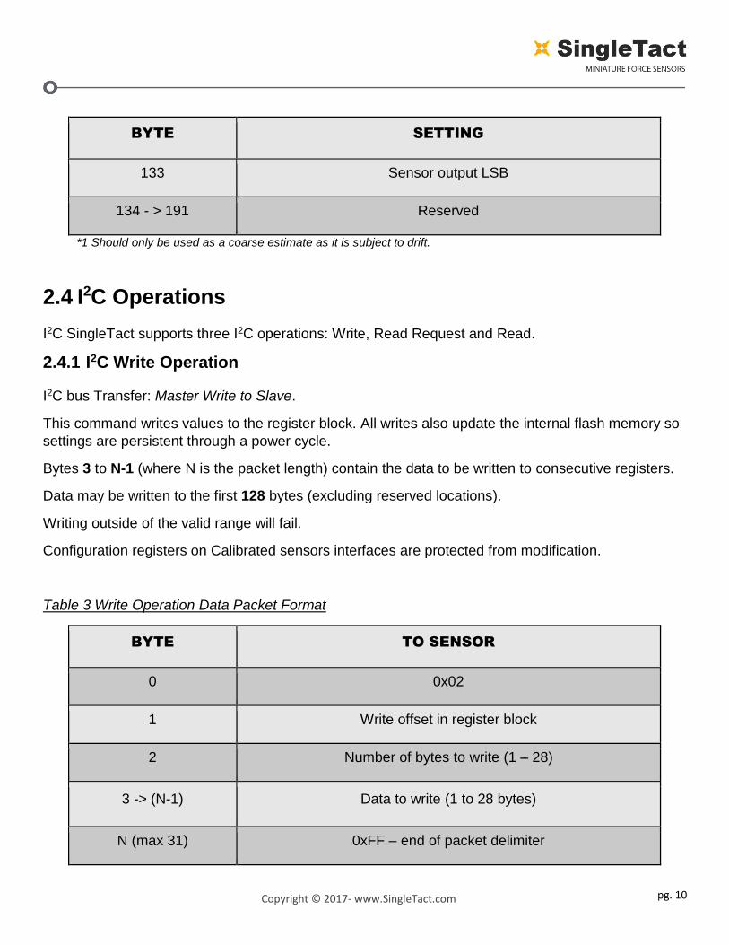
BYTE SETTING
133 Sensor output LSB
134 - > 191 Reserved
*1 Should only be used as a coarse estimate as it is subject to drift.
2.4 I2C Operations
I2C SingleTact supports three I2C operations: Write, Read Request and Read.
2.4.1 I2C Write Operation
I2C bus Transfer: Master Write to Slave.
This command writes values to the register block. All writes also update the internal flash memory so
settings are persistent through a power cycle.
Bytes 3 to N-1 (where N is the packet length) contain the data to be written to consecutive registers.
Data may be written to the first 128 bytes (excluding reserved locations).
Writing outside of the valid range will fail.
Configuration registers on Calibrated sensors interfaces are protected from modification.
Table 3 Write Operation Data Packet Format
BYTE TO SENSOR
0 0x02
1 Write offset in register block
2 Number of bytes to write (1 – 28)
3 -> (N-1) Data to write (1 to 28 bytes)
N (max 31) 0xFF – end of packet delimiter

pg. 11
Copyright © 2017- www.SingleTact.com
2.4.2 I2C Read Request Operation
I2C bus Transfer: Master Write to Slave.
This command sets the read location (register block offset) and read length for a following Read
operation.
Table 4 Read Request Operation Data Packet Format
BYTE TO SENSOR
0 0x01
1 Read offset in register block
2 Number or bytes to read (1 – 32)
3 0xFF – end of packet delimiter
2.4.3 I2C Read Operation
I2C bus Transfer: Master Read from Slave.
An I2C Master Read from Slave transfer can be used to directly read the register set and sensor data.
In normal operation a read of the two Sensor Output byte registers returns a 10-bit output range from
0000 to 0x3FF, corresponding to the 0 to 2V analog output range.
The functional sensor FSR output range is 9-bits from x0100 to 0x2FF, corresponding to the 0.5V to
1.5V analog output range. The larger 10-bit total range allows for detection of negative values when
the sensor is under tension and some level of over pressure detection.
The sensor should be unloaded at power on to allow the sensor’s baseline to be registered correctly.
Where a Read operation is not preceded by a Read Request operation the read location defaults to
128 (the sensor output location) and consecutive reads will therefore simply read the default 32 bytes
of the sensor data region.
Where a Read operating is preceded by a Read Request operation then the register offset and read
length as set by the Read Request will be used.
Data can be read from anywhere in the register block (addresses 0 – 191).

pg. 12
Copyright © 2017- www.SingleTact.com
Reading outside of the valid range will fail.
I2C slave Read operations simply return the register data values up to the number of requested bytes
(32 max) in the data packet.
NOTE: A sensor output reading below 0x0100 may indicate negative pressures, which occur when
the sensing area is under tension. This should be avoided since it can damage the internal structure
of the sensor.
NOTE: Sensor over pressure should be limited to less than 3x FSR to avoid damaging the sensor.
Table 5 I2C Master Read from Slave Data Packet Format
BYTE FROM SENSOR
0 - 31* Register Data Read Location-Read Location+31*
* number of bytes read can be modified by a preceding read-request command.

pg. 13
Copyright © 2017- www.SingleTact.com
2.5 Conversion Detail
The SingleTact electronics interface measures the capacitive sensor with 16-bit precision. This is
scaled to a 10-bit digital (2V analog) output using the following calculation:
Figure 8 Digital Output
The digital scaling value is a 16-bit value stored at register locations 10 and 11 (see Table 2). For
increased precision (within a given sensor’s valid operating range) the digital scaling value can be
adjusted in 0.01 increments. A value of 100 represents unity scaling (100 x 0.01).
The internal capacitance to digital converter (CDC) operates at 140 to 4000 Hz depending on the
capacitance sensor settings (in particular the number of accumulations).
Each time the CDC completes a measurement
OVER
PRESSURE
NEGATIVE
PRESSURE
VALID
RANGE
Force or Pressure
An
alo
g O
utp
ut
0
255
767
1023
FSR 0
𝑺𝒊𝒏𝒈𝒍𝒆𝑻𝒂𝒄𝒕 𝑶𝒖𝒕𝒑𝒖𝒕 = 𝑹𝒂𝒘 𝒄𝒂𝒑𝒂𝒄𝒊𝒕𝒂𝒏𝒄𝒆 − 𝑩𝒂𝒔𝒆𝒍𝒊𝒏𝒆 𝒄𝒂𝒑𝒂𝒄𝒊𝒕𝒂𝒏𝒄𝒆
𝑫𝒊𝒈𝒊𝒕𝒂𝒍 𝒔𝒄𝒂𝒍𝒊𝒏𝒈 𝒗𝒂𝒍𝒖𝒆+ 𝟐𝟓𝟓

pg. 14
Copyright © 2017- www.SingleTact.com
the output register gets updated
the frame index increases by one
an active high pulse is produced on the frame synchronization output pin
a timestamp is generated by SingleTact interface board (however as there is no crystal
oscillator this should only be used as a coarse estimate).
The frame synchronization output (Frame Sync, Figure 4) goes high each time a new measurement is
available. This can be used to synchronize the I2C communications channel to the capacitance
sensor.
Alternatively, the sensor might be polled as quickly as possible over I2C. Since the frame index
increments with each frame it can be used to identify duplicate or missing data readings.
2.6 Product Categories Standard sensors will perform typically to their specified force range. The separately available, generic electronics interface from PPS is suitable for use with the Standard sensors. With a standard sensor fitted and loaded to its specified maximum force (e.g. 45N for a 45N sensor) the scaling factor may be configured via the I2C bus to generate an I2C sensor value equal to 511 and equivalent analog output of 1.5V to ensure the sensor is operating within its valid range. Calibrated sensors offer improved accuracy and linearity over the Standard sensors and come as a
matched sensor plus electronics interface board providing a pre-configured, calibrated linear output
for the specified sensor range, e.g. for an input force of 0 to 10N a 10N calibrated sensor will output a
linear I2C range of 0 to 511 and equivalent analog output of 0.5V to 1.5V.
To maintain calibration, calibrated electronics + sensor combinations as shipped should be
maintained as matched pairs.
To implement multiple sensor solutions multiple sensor interface boards can be connected to a single
I2C bus as described in the I2C Interface section.

pg. 15
Copyright © 2017- www.SingleTact.com
3 TROUBLESHOOTING SingleTact
pg. 16
Copyright © 2017- www.SingleTact.com
3.1 Arduino UNO not detected by PC. Arduino UNO requires to install a driver to communicate over USB port.
Follow the step-by-step instruction from https://www.arduino.cc/en/Guide/HomePage.
3.2 Invalid setting error on PC (Popup reports” Failed to set”). Likely reason:
faulty pin connection.
3.3 No Analog output (remains at 0V). Check wire connections and ensure that you are powering the sensor.
Likely reasons:
Power, Ground or output connection in the wrong place.
power supply is off or faulty.
3.4 Analog output stays at 0.5V.
Likely reason:
Possible sensor fault.
o Check sensor orientation (see Figure 3).
o If in error analog output will stay at 0.49 - 0.5 V.
o Digital output will remain on the baseline (0 counts).

pg. 17
Copyright © 2017- www.SingleTact.com
4 EXAMPLE USE CASE

pg. 18
Copyright © 2017- www.SingleTact.com
4.1 PC and Arduino Example
An Arduino UNO board can be used to implement a USB serial interface to SingleTact.
The code for an Arduino application (source) and an associated .NET based PC DAQ GUI application
(both Windows executable and source) can be downloaded via www.singletact.com.
Once the Arduino board has been programmed with the SingleTact firmware (see Programming the
Arduino UNO with SingleTact Example) the PC application can be run to visually observe the sensor
results.
As the Arduino code is stored in flash the programming (or ‘upload’ in Arduino terms, only needs to
be done once for a new board.
Figure 9 Arduino and SingleTact Assembly
Note: USB communication may need additional driver installation from Arduino software package. See https://www.arduino.cc/en/Guide/Windows#toc4 for further information.

pg. 19
Copyright © 2017- www.SingleTact.com
Figure 10 SingleTact and Arduino UNO Connection
To run the Windows GUI application:
Open the PCExecutable folder.
Run SingleTact Demo.exe to bring up the demonstration application.
Figure 11 Demo of PC DAQ software
The PC application can be used to change the sensor’s I2C address and to modify its output scaling.
For more information on these settings please refer to the I2C Interface section.
CONNECTION
No Connect
Arduino UNO pin A4
No Connect
Arduino UNO GND pin 1
4
3
2
8
5
6
7
CONNECTION
No Connect
Arduino UNO pin A5
No Connect
Arduino UNO 5V pin
PIN NUMBER
*Note: Reference Gain will automatically change depending on the sensor size.

pg. 20
Copyright © 2017- www.SingleTact.com
4.2 Programming the Arduino UNO with SingleTact Example
This process outlines how to program the Arduino UNO with SingleTact example firmware.
1. Download and install the Arduino Software from: https://www.arduino.cc/en/Main/Software
2. Download the Arduino firmware (ExampleArduinoInterface) from: www.singletact.com
3. Connect the Arduino to the PC using the supplied USB cable.
4. Open the Arduino IDE software:
Figure 12 Arduino - PC connection
Note: USB communication may need additional driver installation from Arduino software package. See https://www.arduino.cc/en/Guide/Windows#toc4 for further information.
Follow the step-by-step instructions.
1. Go to File --->Open and open “SingleTactDemo.ino”
2. Go to Sketch --->Include Library --->Add .zip Library and select “Timer1.zip”
3. Go to Sketch --->Verify/Compile.
4. Go to Sketch --- > Upload*.
*Note: If you receive an error on Upload make sure the Arduino is selected under Tools --->Port.
UNO
USB Interface (Arduino Uno) USB Cable

pg. 21
Copyright © 2017- www.SingleTact.com
Figure 13 Arduino integrated development environment
Figure 14 Compiling and uploading the SingleTactDemo.ino file

pg. 22
Copyright © 2017- www.SingleTact.com
4.3 Arduino Demo Outline
The diagrams in this section provide an outline of the Arduino demo functionality as described in the
previous section. In this case the PC to Arduino interface was setup to mirror the I2C interface,
keeping the Arduino code as simple as possible.
Figure 15 Arduino example - communication architecture
Figure 16 Arduino Application flow
PC 1 Arduino Uno N SingleTacts
Request data (I2C)
Send sensor data
Send new data to PC
If new data (compare
itr) - update Graph
repeats repeats
Request data (USB/UART)
Scan
sensors*
repeats
Transfer
to output
buffer
and
timestam
p
Read
output
buffer
*Scan cycle is asynchronous
Loop
Relay commands
over I2C
Command needs
I2C result?
Send result / ack to
PC
Read result over
I2C
Y
Parse command
packet
Y
Timestamp
reading*1
N
New
Command?
N
(*1 Note: The Arduino contains a crystal
oscillator so it is able to produce a more
accurate time stamp than the SingleTact
interface board.)

pg. 23
Copyright © 2017- www.SingleTact.com
On the host, the Arduino appears as a virtual RS-232 serial device. Data is sent to/from the Arduino
using a serial API, such as the one available in .NET.
The Arduino calculates a timestamp for each packet using the Arduino’s crystal controlled oscillator.
This can be used as the time for each sensor.
The serial commands, which mirror the raw I2C commands (as shown in blue in Figure 17), are
outlined in the following tables. Header and footer bytes are added to easily delimit serial packets. A
timeout can be specified for I2C transfers.

pg. 24
Copyright © 2017- www.SingleTact.com
Figure 17 Serial packet structure (sent to Arduino)
BYTE FROM PC TO ARDUINO
0 Header = 0xFF
1 Header = 0xFF
2 Header = 0xFF
3 Header = 0xFF
4 I2C address of sensor
5 Timeout (in 100ms increments)
6 ID (echoed in reply)
7 Read (0x01) or Write (0x02)
8 Read/ write location
9 N bytes to read/ write (max 32)
10-> (10 + N-1) Data to write
0 bytes for read request
11 + N 0xFF – signifies end of packet
12 + N Footer = 0xFF
13 + N Footer = 0xFF
14 + N Footer = 0xFF
15 + N Footer = 0xFF

pg. 25
Copyright © 2017- www.SingleTact.com
Figure 18 Serial packet structure (sent from Arduino)
BYTE FROM ARDUINO TO PC
0 Header = 0xFF
1 Header = 0xFF
2 Header = 0xFF
3 Header = 0xFF
5 1 if timeout exceeded
6 ID (echoed transmit ID)
7 Timestamp MSB
8 Timestamp
9 Timestamp
10 Timestamp LSB
11 N I2C bytes to be sent (max 32)
12 -> 12+N I2C data
13+N Footer = 0xFE
14+N Footer = 0xFE
15+N Footer = 0xFE
16+N Footer = 0xFE

pg. 26
Copyright © 2017- www.SingleTact.com
4.4 Example .NET API
This section provides some detail on the .NET API used to construct the PC GUI application.
Download the .NET Interface and demo application from www.singletact.com.
For convenience the low level PC interface is encapsulated in two .NET components.
1. ArduinoSingleTactDriver – The basic Arduino interface. The user must create one of these.
2. SingleTact – There can be multiple SingleTacts each with their own I2C address.
Creating a SingleTact interface is as simple as:
arduinoSingleTactDriver.Initialise(COMport); //Start Arduino driver
singleTact_.I2cAddressForCommunications = 0x04; //Set I2C address
singleTact_.Initialise(arduinoSingleTactDriver); //Start sensor
The sensor is read using the following:
SingleTactFrame newFrame = singleTact_.ReadSensorData(); //Get sensor data
if (null != newFrame) //If we have data
{//Process result}
Settings can be pulled from the sensor using:
singleTact_.PullSettingsFromHardware();
and sent to the sensor using:
singleTact_.PushSettingsToHardware();
NOTE: The sensor settings can be modified using commands such as:
singleTact_.Settings.ReferenceGain = ###

pg. 27
Copyright © 2017- www.SingleTact.com
5 Resources
SingleTact homepage http://www.singletact.com/ I2C-bus specification and user manual VERSION 6, April 2014 http://www.nxp.com/documents/user_manual/UM10204.pdf Arduino home https://www.arduino.cc/ Microsoft .NET Framework https://www.microsoft.com/net

pg. 28
Copyright © 2017- www.SingleTact.com
6 Glossary
API Application Program Interface
CDC Capacitance to Digital Converter
DAQ Data Acquisition
FFC Flexible Flat Cable (connector)
FSR Full Scale Range
I2C Inter IC bus
IDE Integrated Development Environment
LSB Least Significant Byte
MSB Most Significant Byte
.NET A Microsoft .NET software framework
NVM Non-Volatile Memory
RS-232 A serial communications standard

pg. 29
Copyright © 2017- www.SingleTact.com
7 Revision History
Revision 2.0
1) Removed Section 3 Updating the Interface Board.
2) Updated Table 1 accessibility to interface board design detail.
Revision 2.1
1) Added Revision History.
2) Section 1: Referenced Calibrated and Uncalibrated product options.
3) Figure 2: Fixed the link in footnote 3.
4) Table 1: Added I2C Sensor Output range.
5) Table 2: Corrected the addresses of the following parameters:
40 Delimiter – leave as 0xFF
41 Sensor baseline MSB
42 Sensor baseline LSB
Were 39, 40, & 41 respectively.
6) Section 2.3 Removed reference to I2C high speed mode. Updated detail on multiple sensor interfaces
sharing a single I2C bus
7) Section 2.4.3: Added detail on I2C Sensor Output data values.
8) Section 2.5: corrected output scale resolution from 12-bit to 10-bit and clarified operating output
values.
9) Added Section 2.6 Product Categories.
10) Figure 10: Removed Set Reference Gain control from the GUI image (the Reference Gain Setting is
automatic in the current interface board design).
Revision 2.2
1) Fixed Table 1 to show correct maximum supply voltage (12V rather than 5V as stated)
2) Updated Copyright year to 2017
Revision 2.3
1) Clarified 255 digital offset and added Figure 8 to demonstrate.
2) Add manual version to page 1.