user’s manual - etichette adesive personalizzate e … · trakker antares 241x hand-held terminal...
TRANSCRIPT
P/N 069538-002
User’s Manual
Trakker Antares®
241X Hand-Held Terminal
Intermec Technologies Corporation6001 36th Avenue WestP.O. Box 4280Everett, WA 98203-9280
U.S. service and technical support: 1.800.755.5505U.S. media supplies ordering information: 1.800.227.9947
Canadian service and technical support: 1.800.688.7043Canadian media supplies ordering information: 1.800.268.6936
Outside U.S. and Canada: Contact your local Intermec service supplier.
The information contained herein is proprietary and is provided solely for the purpose of allowing customersto operate and/or service Intermec manufactured equipment and is not to be released, reproduced, or used forany other purpose without written permission of Intermec.
Information and specifications in this manual are subject to change without notice.
1999 by Intermec Technologies CorporationAll Rights Reserved
The word Intermec, the Intermec logo, JANUS, IRL, Trakker Antares, EZBuilder, Universal Access Point, andCrossBar are either trademarks or registered trademarks of Intermec.
Throughout this manual, trademarked names may be used. Rather than put a trademark ( or ) symbol inevery occurrence of a trademarked name, we state that we are using the names only in an editorial fashion, andto the benefit of the trademark owner, with no intention of infringement.

nuggetf code39
Manual Change RecordThis page records changes to the manual. The manual was released at Revision 001.
Revision Date Description of Change
002 8/99 This manual was revised to add the dcBrowser information sheet,Part No. 070012-001.

nuggetf code39
blank

nuggetf code39 Contents
v
ContentsBefore You Begin xv
Warranty Information xvSafety Summary xvWarnings and Cautions xviAbout This Manual xviOther Intermec Manuals xix
Learning About the TerminalsWhat Are the Trakker Antares 241X Terminals? 1-3
Options for the Terminals 1-4Accessories for the Terminals 1-5
Understanding the Terminal’s Features 1-6
Using the Terminal’s Keypad 1-7How to Type the Characters Printed on the Keypad 1-7Finding the Special Keys 1-8
Using the Suspend/Resume Key 1-9Using the Function Left, Function Right, and Shift Keys 1-9Capitalizing All Characters 1-10Using the Cursor Keys 1-10
Using the International Keypad 1-11Using the TE Keypads 1-12
Using the Terminal’s Serial Port 1-13
Using the Terminal’s Screen 1-14
Understanding the Terminal’s Status LEDs 1-15
Understanding the Terminal’s Status Beeps 1-16
Connecting an Input Device to the Terminal 1-17
Using the Terminal’s Battery Pack 1-18Determining When the Battery Pack is Low 1-18Charging the Battery Pack 1-19Installing the Battery Pack 1-19Removing the Battery Pack 1-20Managing Battery Power 1-21
Defining the Terminal’s Drives 1-22
1

Trakker Antares 241X Hand-Held Terminal User’s Manual nuggetf code39
vi
Using the Terminal’s Scanner 1-23Scanning Options 1-26
Using the Terminal for the First Time 1-27
Operating the Terminals in a NetworkHow the Terminals Fit Into Your Network 2-3
Connecting the Terminal to a Wired Network 2-10Choosing a Communications Protocol 2-10
Binary Protocol 2-11Configurable Protocol 2-11Master Polling Protocol 2-12Point-to-Point Protocol 2-12Polling Mode D Protocol 2-12
Connecting the 2415 to an RF Network 2-13Planning the Network Connection 2-13Configuring the DCS 300 2-14Configuring the Access Point 2-14
2.4 GHz OpenAir Network 2-15IEEE 802.11 DS Network 2-15
About the Network Parameters 2-16Monitoring RF Communications Using the Status LEDs 2-17
About Network Connectivity and Protocols 2-18
Configuring the TerminalsHow to Configure the Terminal 3-3
About the Configurations 3-3
Configuring the Terminal With the Menu System 3-4Accessing Online Help 3-6Selecting Menus and Commands 3-6Filling In Fields 3-7Marking Check Boxes 3-8Entering ASCII Control Characters 3-9Exiting the Menu System 3-11
Configuring the Terminal by Scanning Bar Code Labels 3-13
Configuring the Terminal Through the Serial Port 3-15
2
3

nuggetf code39 Contents
vii
Configuring the 2415 Through the Network 3-17Sending a Command From the DCS 300 3-17Sending a Command From the Host 3-19
Configuring the 2415 in a UDP Plus Network 3-19Configuring the 2415 in a TCP/IP Direct Connect Network 3-20
Transferring Files in a TCP/IP Direct Connect Network 3-23
Saving Configuration Changes to Flash Memory 3-28
Restoring the Terminal’s Default Configuration 3-29
Using Custom ApplicationsHow To Download and Run Applications 4-3
About the Trakker Antares Programmable Terminals 4-4
Creating Applications for the Terminal 4-6Using the PSK or EZBuilder to Develop Applications 4-6
Converting Applications Between JANUS and Trakker Antares 4-7Converting IRL Programs 4-7
Converting the Application to a Binary File 4-8
Using the Serial Port to Transfer Applications and Files 4-9
Using the DCS 300 to Download Applications and Files 4-14Copying Applications and Files to the DCS 300 4-14Downloading Applications and Files to the 2415 4-16
Running the Application on the Terminal 4-19
Using Screen Mapping (DCS 300 v1.1) 4-21
Troubleshooting and Maintaining the TerminalsHow to Use This Chapter 5-3
Finding and Solving Problems 5-4Terminal Will Not Turn On 5-5Problems While Operating the Terminal 5-5Problems While Configuring the Terminal 5-72415 Will Not Communicate With RF Network Devices 5-12Problems Transmitting Data Through the Serial Port 5-14
4
5

Trakker Antares 241X Hand-Held Terminal User’s Manual nuggetf code39
viii
Problems Transmitting Data Through the DCS 300 5-15Bar Code Labels Will Not Scan 5-16
Booting and Resetting the Terminal 5-18Booting the Terminal 5-18
Booting the Terminal on Resume 5-18Using the Boot Menu 5-19
Resetting the Terminal 5-20
Cleaning the Scanner Window and Terminal Screen 5-21
Upgrading the Terminal 5-22Upgrading the Firmware 5-22Loading Double-Byte Fonts 5-25
Running DiagnosticsWhat Diagnostics Are Available? 6-3
Running Diagnostics From the Menu System 6-5
Defining the Diagnostics Screens 6-7Defining the Software Diagnostics Screens 6-7
Application Events 6-7Clear Task Profiles 6-8Error Logger 6-9Task Status 6-10
Defining the Hardware Diagnostics Screens 6-11Battery/PIC Status 6-11Beeper Test 6-12Destructive RAM Test 6-13Display Test 6-14Hardware Configuration 6-15Keypad Test 6-16Radio Test 6-17Scanner Test 6-18Serial Port Loopback Test 6-19
Defining the System Diagnostics Screens 6-20Access Point 6-20Application Efficiency 6-21Malloc Application Information 6-22Malloc Firmware Information 6-23Serial Port Test 6-24Subsystem Versions 6-25
6

nuggetf code39 Contents
ix
Reader Command ReferenceUsing Reader Commands 7-3
Using Accumulate Mode 7-4Backspace 7-5Clear 7-5Enter 7-6Enter Accumulate Mode 7-6Exit Accumulate Mode 7-6
Operating Reader Commands 7-7Backlight On and Off 7-7Boot Terminal 7-8Change Configuration 7-8Default Configuration 7-9Multiple-Read Labels 7-9Reset Firmware 7-10Save Configuration in Flash Memory 7-10Scanner Trigger On and Off 7-11Set Time and Date 7-12Test and Service Mode 7-12
File Management Reader Commands 7-13Abort Program 7-13Delete File 7-14List Files 7-15Receive File 7-15
Receive File Through the Serial Port 7-15Receive and Convert 7-Bit ASCII Files to 8-Bit Binary Files 7-17Receive File Via RF Communications 7-19
Rename File 7-21Run Program 7-22Transmit File 7-23
Transmit File Through the Serial Port 7-23Transmit and Convert 8-Bit Binary Files to 7-Bit ASCII Files 7-25Transmit File Via RF Communications 7-27
7

Trakker Antares 241X Hand-Held Terminal User’s Manual nuggetf code39
x
Configuration Command ReferenceUsing Configuration Commands 8-3
Configuration Commands Listed by Category 8-4
Entering Variable Data in a Configuration Command 8-6
Acknowledgement Delay Lower Limit 8-7
Acknowledgement Delay Upper Limit 8-9
AP Density 8-11
Append Time 8-12
Automatic Shutoff 8-13
Baud Rate 8-15
Beep Volume 8-17
Codabar 8-19
Code 11 8-21
Code 16K 8-22
Code 2 of 5 8-23
Code 39 8-25
Code 49 8-29
Code 93 8-31
Code 128 8-32ISBT Code 128 8-33
Command Processing 8-39
Configuration Commands Via Serial Port 8-43
Controller Connect Check Receive Timer 8-45
Controller Connect Check Send Timer 8-47
Controller IP Address 8-49
Data Bits 8-51
8

nuggetf code39 Contents
xi
Decode Security 8-52
Default Router 8-53
Display Backlight Timeout 8-55
Display Contrast 8-57
Display Font Grid Type 8-58
Display Row Spacing 8-59
Display Video Mode 8-60
Domain 8-61
Dynamic Host Configuration Protocol (DHCP) 8-63
End of Message (EOM) 8-64
Flash Memory Configuration 8-66
Flow Control 8-68
Handshake 8-70
Host IP Address 8-71
Inactivity Timeout 8-73
Interleaved 2 of 5 8-75
Keypad Caps Lock 8-77
Keypad Clicker 8-78
Keypad Type 8-79
LRC (Longitudinal Redundancy Check) 8-81
Maximum Retries 8-82
Maximum Sleep Duration 8-84
MSI 8-86
Network Activate 8-88
Network Loopback 8-89
Network Name 8-90

Trakker Antares 241X Hand-Held Terminal User’s Manual nuggetf code39
xii
Network Port 8-92
Parity 8-94
Plessey 8-95
Poll (Polling) 8-96
Postamble 8-97
Power Management 8-99
Preamble 8-100
RAM Drive Size 8-102
Receive All Multicast 8-104
Reservation 8-105
Reservation Enable 8-107
Resume Execution 8-108
Roaming Flag 8-109
Scan Ahead 8-110
Scanner Mode 8-111
Scanner Redundancy 8-112
Scanner Selection 8-113
Scanner Timeout 8-114
Scanner Trigger 8-116
Security Identification 8-117
Serial Port Protocol 8-118
Start of Message (SOM) 8-120
Station Name 8-122
Stop Bits 8-123
Subnet Mask 8-124
Suspend/Resume Control 8-126

nuggetf code39 Contents
xiii
TCP Maximum Retries 8-127
TCP/IP Maximum Transmit Timeout 8-129
Terminal IP Address 8-131
Time and Date 8-133
Time in Seconds 8-135
Timeout Delay 8-136
Transmit Mode 8-138
Transmit Rate 8-139
UPC/EAN 8-140
Wakeup On Broadcast 8-143
Specifications and Other Helpful InformationSpecifications A-3
Default Configuration A-9
Configuration Commands by Syntax A-13
Full ASCII ChartsFull ASCII Table B-3
Full ASCII Bar Code Chart B-6Control Characters B-6Symbols and Punctuation Marks B-7Numbers B-8Uppercase Letters B-9Lowercase Letters B-10
International Character SupportTrakker Antares Terminal Font Set C-3
English and Western European Font Set C-3Japanese Katakana Font Set C-13
A
B
C
Trakker Antares 241X Hand-Held Terminal User’s Manual nuggetf code39
xiv
Using the Default ApplicationsAbout the Applications Shipped on the Terminal D-3
Defining APPTSK.BIN and EM9560.BIN D-3Defining the Emulation Features of EM9560.BIN D-4
Using Display Control Codes D-5Setting Preambles and Postambles D-6Full ASCII Mode for Code 39 D-7Unsupported 95XX Features D-9
Running APPTSK.BIN and EM9560.BIN D-9
Index
D
I

nuggetf code39 Before You Begin
xv
Before You BeginThis section introduces you to standard warranty provisions, safety precautions,warnings and cautions, document formatting conventions, and sources of additionalproduct information. A list of Intermec manuals is also provided to guide you in findingthe appropriate information.
Warranty InformationTo receive a copy of the standard warranty provision for this product, contact your localIntermec support services organization. In the U.S. call 1-800-755-5505, and in Canadacall 1-800-688-7043. Otherwise, refer to the Worldwide Sales & Service list that shipswith this manual for the address and telephone number of your Intermec salesorganization.
Safety SummaryYour safety is extremely important. Read and follow all warnings and cautions in thisbook before handling and operating Intermec equipment. You can be seriously injured,and equipment and data can be damaged if you do not follow the safety warnings andcautions.
Do not repair or adjust alone Do not repair or adjust energized equipment aloneunder any circumstances. Someone capable of providing first aid must always bepresent for your safety.
First aid Always obtain first aid or medical attention immediately after an injury.Never neglect an injury, no matter how slight it seems.
Resuscitation Begin resuscitation immediately if someone is injured and stopsbreathing. Any delay could result in death. To work on or near high voltage, you shouldbe familiar with approved industrial first aid methods.
Energized equipment Never work on energized equipment unless authorized by aresponsible authority. Energized electrical equipment is dangerous. Electrical shockfrom energized equipment can cause death. If you must perform authorized emergencywork on energized equipment, be sure that you comply strictly with approved safetyregulations.
Note: For laser compliance and safety information, refer to the manual supplement thatshipped with your Trakker Antares® 241X hand-held terminal.

Trakker Antares 241X Hand-Held Terminal User’s Manual nuggetf code39
xvi
Warnings and CautionsThe warnings and cautions in this manual use the following format.
WarningA warning alerts you of an operating procedure, practice, condition, or statementthat must be strictly observed to avoid death or serious injury to the persons workingon the equipment.
AvertissementUn avertissement vous avertit d’une procédure de fonctionnement, d’une méthode,d’un état ou d’un rapport qui doit être strictement respecté pour éviter l’occurrencede mort ou de blessures graves aux personnes manupulant l’équipement.
CautionA caution alerts you to an operating procedure, practice, condition, or statement thatmust be strictly observed to prevent equipment damage or destruction, or corruptionor loss of data.
ConseilUne précaution vous avertit d’une procédure de fonctionnement, d’une méthode,d’un état ou d’un rapport qui doit être strictement respecté pour empêcherl’endommagement ou la destruction de l’équipement, ou l’altération ou la perte dedonnées.
Notes: Notes are statements that either provide extra information about a topic orcontain special instructions for handling a particular condition or set of circumstances.
About This ManualThis manual contains all of the information necessary to install, configure, operate, andtroubleshoot the Trakker Antares 2410 and 2415 terminals.
This manual was written for two audiences:
• All users who need to know how to use the terminal to collect data.
• MIS personnel, operations personnel, analysts, and programmers who need to knowhow to install, configure, test, and use the terminal to operate in a network. Youshould have a good knowledge of your company’s network and data collectionsoftware. You should be familiar with data communications and network protocols.

nuggetf code39 Before You Begin
xvii
TerminologyYou should be aware of how these terms are being used in this manual:
Term Description
Host The term “host” refers to a personal computer or other computer thatcommunicates with the terminal.
DCS 300 The term “DCS 300” refers to the new data collection server thatreplaces the Model 200 Controller. Unless otherwise noted, you canuse either the DCS 300 or the Model 200 Controller.
2410 The term “2410” indicates the specific type of terminal, the TrakkerAntares 2410 terminal.
2415 The term “2415” indicates the specific type of terminal, the TrakkerAntares 2415 terminal.
Terminal The generic term “terminal” indicates either the Trakker Antares2410 terminal or the Trakker Antares 2415 terminal.
Trakker Antares The term “Trakker Antares” identifies the product family of TrakkerAntares terminals, which includes the hand-held terminals, vehicle-mount terminals, stationary terminals, and light industrial terminals.
Conventions for Software Screens and MessagesThis manual includes illustrations that represent how the terminals display softwarescreens and messages. Here are two examples:
MAIN MENU Configuration Menu Diagnostics Menu System Menu About TRAKKER 2400 _` Select item [Enter] Next screen [F1] Help [Esc] Exit
241XU034.eps
SYSTEM MENU Load Default Values Set Time and Date Store Configuration Upgrade Firmware _` Select item [Enter] Next screen [F1] Help [Esc] Exit

Trakker Antares 241X Hand-Held Terminal User’s Manual nuggetf code39
xviii
Conventions for Bar CodesYou can scan the bar codes listed in this manual to enter data or perform a command.The bar code labels in this manual are printed in the Code 39 symbology. Each bar codeincludes the name and human-readable interpretation. For example:
*$+*
Change Configuration
*$+*
Name
Bar code (Code 39)
Human-readableinterpretation
242XU.146
The asterisks (*) at the beginning and end of the human-readable interpretation are thestart and stop codes for a Code 39 bar code label. If you are using a bar code printingutility, it may automatically supply the asterisks as the start and stop code, so that youonly need to type the actual text of the command. You can also create and printconfiguration labels and reader command labels in Code 93, which has its own start andstop codes.
Conventions for Input From a Keypad or KeyboardThis table describes the formatting conventions for input from PC keyboards, hostcomputer keyboards, and terminal keypads:
Convention How to Interpret the Convention
Bold text Indicates the keys you must press on a PC or host computer keyboard.For example, “press Enter” means you press the key labeled “Enter” onthe PC or host computer keyboard.
� Shows the key you must press on the terminal. For example, “press �”directs you to press the A key on the terminal keypad.
9 � � � Shows a series of terminal keys you must press and release in the ordershown. For example, “Press 9 � � � to run the TRAKKER Antares2400 Menu System.”

nuggetf code39 Before You Begin
xix
Conventions for CommandsThis manual includes sample commands that are shown exactly as you should typethem on your terminal or network device. The manual also describes the syntax formany commands, defining each parameter in the command. This table defines theconventions that are used in this manual.
Convention DescriptionSpecial font Commands appear in Courier font. You enter the command exactly
as it is shown.
Required parameters If a parameter is not enclosed in brackets [ ], the parameter isrequired. You must include the parameter in the command;otherwise, the command will not execute correctly.
[ ] Brackets enclose a parameter that you may omit from the command.Do not include the brackets in the command.
Italic text Italics indicate a variable, which you must replace with a real value,such as a number, filename, keyword, or command.
Where This word introduces a list of the command’s parameters andexplains the values you can specify for them.
Other Intermec ManualsYou may need additional information when working with the terminal in a datacollection system. Please visit our Web site at www.intermec.com, which providesmany of our current manuals in PDF format that you can download. To order printedversions of the Intermec manuals, contact your local Intermec representative ordistributor.
ManualIntermecPart No.
Trakker Antares 241X Hand-Held Terminal Getting Started Guide 069540
Trakker Antares 241X Battery Pack Instruction Sheet 069547
Trakker Antares 2-Pack Charger Instruction Sheet 069548
Trakker Antares TZ2410 Battery Charger Instruction Sheet 069549
Trakker Antares TD2410 Communications Dock Quick Reference Guide 069552
Trakker Antares 241X Belt Clip Instruction Sheet 069553
Trakker Antares 241X Handle Instruction Sheet 069557
Trakker Antares 241X Handstrap Instruction Sheet 069554
Trakker Antares 241X Holster Instruction Sheet 069556
TE 2000 VT/ANSI Terminal Emulation Programmer’s Guide 977-055-005
TE 2000 5250 Terminal Emulation Programmer’s Guide 977-055-004

xx
blank

Co de 39 Nugget
Learning About the Terminals
1

Co de 39 Nugget
1-2

Co de 39 Nugget Learning About the Terminals
1-3
1This chapter explains the terminals’ features, including the status LEDs, status beeps,battery pack, and drives. It also lists the options and accessories you can order.
What Are the Trakker Antares 241X Terminals?The Trakker Antares 2410 and 2415 terminals are small, lightweight, hand-held datacollection terminals that are designed for a range of applications, including commercialapplications such as in-store retail.
241X001.eps
2410 The Trakker Antares 2410 terminal is a programmable data collection terminalthat runs custom batch applications. The terminal has a flash drive to store applicationsand files. The 2410 has an integrated I/O port to transmit data to and accept data from ahost or PC via RS-232 serial communications.
2415 The Trakker Antares 2415 terminal has all of the capabilities of the 2410 and itcan also communicate in a radio frequency (RF) network. Because it can communicateusing RF, the 2415 provides real-time communications to a host either through the accesspoints and the DCS 300 or directly through the access points. The 2415 can also runclient/server applications and TE 2000 terminal emulation applications.
Trakker Antares 241X Hand-Held Terminal User’s Manual Co de 39 Nugget
1-4
Options for the TerminalsThese options are available for the 2410:
• Programmable terminal with 55-key alphanumeric, 37-key alphanumeric with largenumeric, or 37-key function key with large numeric keypads. Each keypad supportsoverlays for English or international languages.
• Laser scanner (standard, long range, high density, high visibility)
• 4MB flash memory, configured as an additional 2MB flash drive for customapplications (except .BIN files) and files or pre-loaded with different Asian fonts
• 2MB or 4MB extended storage drive, used for custom applications or files
These options are available for the 2415:
• Programmable terminal with 55-key alphanumeric, 37-key alphanumeric with largenumeric, and 37-key function key with large numeric keypads available. Each keypadsupports overlays for English or international languages.
• IBM 5250 TE application and alphanumeric keypad
• VT100/220/320/340 and ANSI TE application and 55-key alphanumeric, 37-keyalphanumeric with large numeric, or 37-key function key with large numeric keypads
• Laser scanner (standard, long range, high density, high visibility)
• 4MB flash memory, configured as an additional 2MB flash drive for customapplications (except .BIN files) and files or pre-loaded with different Asian fonts
• UDP Plus (DCS 300 to host) or TCP/IP (direct connect to host)
• 2.4 GHz OpenAir radio or IEEE 802.11 DS radio
Co de 39 Nugget Learning About the Terminals
1-5
1Accessories for the TerminalsYou can use these accessories (sold and ordered separately) with the terminals:
Standard (Single-Cell) or High Performance (Dual-Cell) Battery Packs Theselithium-ion battery packs (Part No. 069428 and Part No. 069429) provide the mainpower to the terminal.
Battery Chargers The 2-pack charger (Part No. 069582) lets you charge up to twobattery packs at one time. The 4-pack charger (TZ2410) lets you charge up to fourbattery packs at one time. The battery charger senses when a battery pack is fullycharged and will not overcharge it, ensuring long and consistent battery pack life.
Communications Dock When you place the terminal in the communications dock(TD2410), the terminal can communicate with a host computer or PC via RS-232 serialcommunications. If you connect a power supply to the dock, you can also charge thebattery pack.
Handstrap The elastic handstrap (Part No. 069580) attaches to the back of theterminal to let you hold the terminal easily and securely for long periods of use.
Handle The pistol-grip handle (Part No. 069588)provides a convenient way to holdthe terminal.
Belt Clip The belt clip (Part No. 069581) lets you attach the terminal to your belt andhave it hang at your side so you can have both hands free.
Holster and Belt The holster and belt (Part No. 069583) are a convenient way for youto carry the terminal when you are not using it.
Trakker Antares 241X Hand-Held Terminal User’s Manual Co de 39 Nugget
1-6
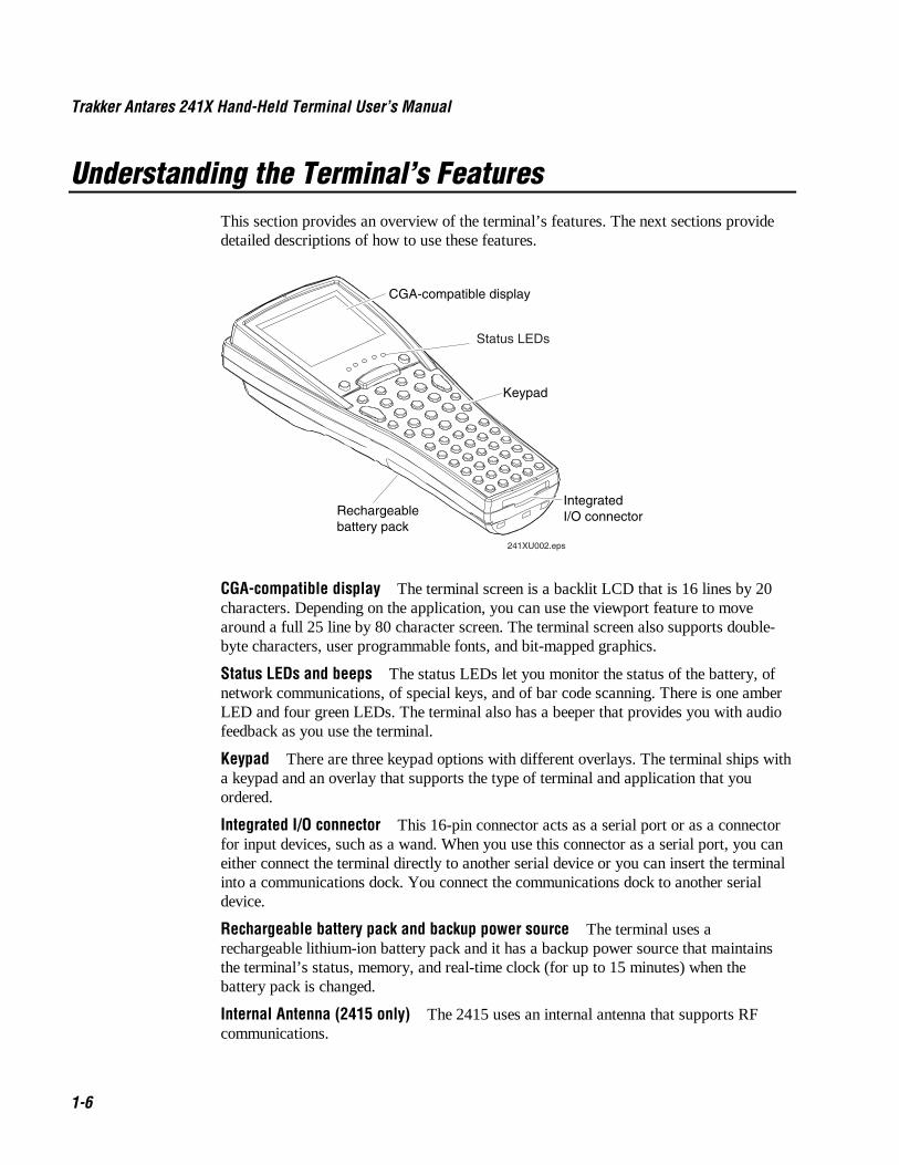
Understanding the Terminal’s FeaturesThis section provides an overview of the terminal’s features. The next sections providedetailed descriptions of how to use these features.
Rechargeable battery pack
CGA-compatible display
Keypad
IntegratedI/O connector
241XU002.eps
Status LEDs
CGA-compatible display The terminal screen is a backlit LCD that is 16 lines by 20characters. Depending on the application, you can use the viewport feature to movearound a full 25 line by 80 character screen. The terminal screen also supports double-byte characters, user programmable fonts, and bit-mapped graphics.
Status LEDs and beeps The status LEDs let you monitor the status of the battery, ofnetwork communications, of special keys, and of bar code scanning. There is one amberLED and four green LEDs. The terminal also has a beeper that provides you with audiofeedback as you use the terminal.
Keypad There are three keypad options with different overlays. The terminal ships witha keypad and an overlay that supports the type of terminal and application that youordered.
Integrated I/O connector This 16-pin connector acts as a serial port or as a connectorfor input devices, such as a wand. When you use this connector as a serial port, you caneither connect the terminal directly to another serial device or you can insert the terminalinto a communications dock. You connect the communications dock to another serialdevice.
Rechargeable battery pack and backup power source The terminal uses arechargeable lithium-ion battery pack and it has a backup power source that maintainsthe terminal’s status, memory, and real-time clock (for up to 15 minutes) when thebattery pack is changed.
Internal Antenna (2415 only) The 2415 uses an internal antenna that supports RFcommunications.

Co de 39 Nugget Learning About the Terminals
1-7
1Using the Terminal’s Keypad
The terminal has three keypad options:
• (55-key) Alphanumeric keypad
• (37-key) Alphanumeric with large numeric keypad
• (37-key) Function keys with large numeric keypad
Each of these keypads has overlay options:
• Programmable
• International
• (2415 only) VT100/220/320/340 and ANSI keypad
• (2415, 55-key only) 5250 TE keypad
Although the keypads are smaller than a standard PC or terminal keyboard, you can usespecial keys to access all the keys and functions that you need. For a complete list of allof the keys that you can type, see the “Quick Reference Keypad Chart” in Appendix A.
How to Type the Characters Printed on the KeypadThe keypads are easy to use. Characters, symbols, and functions are printed in fourplaces on or above the keys. The keys are also color-coded to make it easier to rememberkey combinations.
Position on the Keypad Color To Type the Character
Middle of the key White Press the key.
Left side above the key Orange Press the orange � key, then the key.
Centered above the key Pink Press the pink � key, then the key.
Right side above the key Green Press the green key, then the key.
To type characters using the keypad
Fld+ * Fld-
8241XU003.eps
8
8
8
8
Trakker Antares 241X Hand-Held Terminal User’s Manual Co de 39 Nugget
1-8
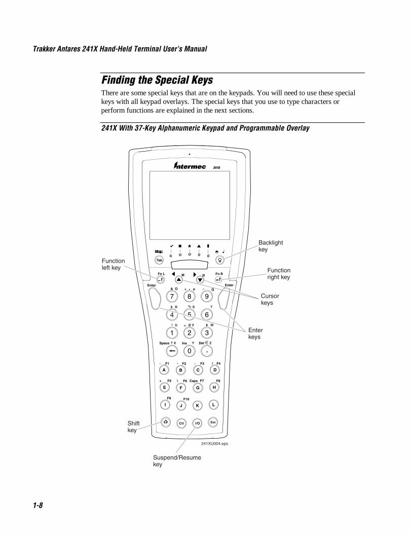
Finding the Special KeysThere are some special keys that are on the keypads. You will need to use these specialkeys with all keypad overlays. The special keys that you use to type characters orperform functions are explained in the next sections.
241X With 37-Key Alphanumeric Keypad and Programmable Overlay
Tab
2410
Fn L Fn R
Enter Enter
M N
O P Q
R
>
< "& *
$
#
Space DelIns
Caps
,
+
:
\
/ - F1 F2 F3 F4
F5 F6 F7 F8
F9 F10
241XU004.eps
Backlightkey
Cursorkeys
Suspend/Resumekey
Shiftkey
Functionleft key Function
right key
Enter keys
%
! U
? X Y Z
@ V W
S T
Co de 39 Nugget Learning About the Terminals
1-9
1Using the Suspend/Resume KeyThe Suspend/Resume key is the : key in the middle of the bottom row of the keypad.When you press : to turn off the terminal, the terminal does not actually shut off, butgoes into a Suspend mode. In Suspend mode, the terminal continues to power all memoryand turns off the power to most of the hardware. This mode is referred to as “off” in therest of this manual.
When you press : to turn on the terminal, the terminal either resumes exactly where itwas when you turned it off, or the terminal boots and restarts your application. Resume iscontrolled through a parameter or command called Resume Execution. For help, see“Resume Execution” in Chapter 8.
Even if you change the battery pack while the terminal is turned off, the terminal resumesor boots the next time the terminal is turned on.
Using the Function Left, Function Right, and Shift KeysThe keypad does not have a physical key for every character and function available. Youuse the Function Left (FnL), Function Right (FnR), and Shift keys to access characters orperform functions that do not have a physical key on the keypad. You also use the Shiftkey to type uppercase alphabetic characters.
When you press �, , or �, the key is held in a buffer until you press another key. TheModifier LED turns on to remind you that the key is being held in the buffer. When youpress another key, the key combination is entered into the terminal. The Modifier LEDturns off, unless the second key that you pressed is another modifier key that is differentfrom the first one that you pressed.
To flush the �, , or � key from the buffer without performing any action, press thekey again. The Modifier LED turns off.
To use the FnL, FnR, and Shift keys
1. Press �, , or �. The Modifier LED turns on.
2. Press the second key. The Modifier LED turns off.
For example, to type the uppercase letter A, press �. The Modifier LED turns on. Press�. The Modifier LED turns off and an A appears on the screen.

Trakker Antares 241X Hand-Held Terminal User’s Manual Co de 39 Nugget
1-10
Capitalizing All CharactersTo type all alphabetic characters as uppercase letters, you either press � before everyletter you type or you enable the Caps Lock feature.
Note: You can also use the Keypad Caps Lock configuration command to enable ordisable Caps Lock on the terminal. For help, see “Keypad Caps Lock” in Chapter 8.
To enable Caps Lock
1. Press �. The Modifier LED turns on.
2. (37-key function key/numeric) Press 9.
(37-key alphanumeric/numeric) Press #.
(55-key alphanumeric) Press 1.
3. Type an alphabetic character. The letter appears as an uppercase character on theterminal’s screen. The Modifier LED remains on until you disable Caps Lock.
To type a lowercase letter with Caps Lock enabled
• Press � and an alphabetic character.
To disable Caps Lock
1. Press �.
2. (37-key function key/numeric) Press 9.
(37-key alphanumeric/numeric) Press #.
(55-key alphanumeric) Press 1.
3. Type an alphabetic character. The letter appears as a lowercase letter on theterminal’s screen. The Modifier LED turns off.
Using the Cursor KeysYou can press the cursor keys to move the cursor around an application screen. Thecursor keys work the same as cursor keys on a regular keyboard.
To Use This Cursor Key Press Description
Arrow up � Moves the cursor up one row or line.
Arrow down � Moves the cursor down one row or line.
Arrow left � � Moves the cursor one character to the left.
Arrow right � � Moves the cursor one character to the right.

Co de 39 Nugget Learning About the Terminals
1-11
1Using the International KeypadWhether your terminal has an alphanumeric or a numeric keypad, you can order it withan international overlay. This overlay supports English and most Western Europeanlanguages, such as French, German, Italian, Portuguese, Spanish, and others.
Like the programmable keypads, you use the international keypad to enter all thecharacters printed on or above the keys. For help, see “How to Type the CharactersPrinted on the Keypad” earlier in this chapter. This keypad also comes with the samespecial keys that are on the programmable overlay. For help, see “Finding the SpecialKeys” earlier in this chapter.
Note: Some keys on the 37-key international keypads let you access five different keys.To type the light green character that is printed on the far right side above the key, pressthe ; key and then the key.
241X With 55-Key Alphanumeric Keypad and International Overlay
Tab
7 8 9
4 5 6
0 .
1 2 3
Ctl Esc
A B C D E
F G H I J
K L M ON
I/O
F2 F4
F1
Fn L Fn R
Fld Ext Enter
P Q R TS
U V W X Y
Z
2410
f
^
ƒ
«‘
£
><
f
⁄
~
~ + {
: = [
] ;
/
‘
_
-
\
Caps
'?
,
F5
}
F7
F8F6
F9
Space DelIns
F10 F3
)
(
%
& *
$ ^
@! #‹
? !
˙
¨
…»
§
241XU005.eps
Trakker Antares 241X Hand-Held Terminal User’s Manual Co de 39 Nugget
1-12
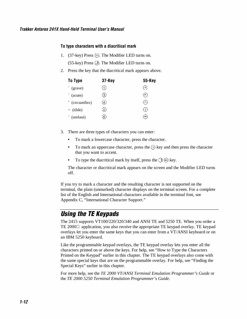
To type characters with a diacritical mark
1. (37-key) Press ;. The Modifier LED turns on.
(55-key) Press . The Modifier LED turns on.
2. Press the key that the diacritical mark appears above.
To Type 37-Key 55-Key
` (grave) � �
´ (acute) � �
ˆ (circumflex) � �
~ (tilde) � �
¨ (umlaut) � �
3. There are three types of characters you can enter:
• To mark a lowercase character, press the character.
• To mark an uppercase character, press the � key and then press the characterthat you want to accent.
• To type the diacritical mark by itself, press the � � key.
The character or diacritical mark appears on the screen and the Modifier LED turnsoff.
If you try to mark a character and the resulting character is not supported on theterminal, the plain (unmarked) character displays on the terminal screen. For a completelist of the English and International characters available in the terminal font, seeAppendix C, “International Character Support.”
Using the TE KeypadsThe 2415 supports VT100/220/320/340 and ANSI TE and 5250 TE. When you order aTE 2000 application, you also receive the appropriate TE keypad overlay. TE keypadoverlays let you enter the same keys that you can enter from a VT/ANSI keyboard or onan IBM 5250 keyboard.
Like the programmable keypad overlays, the TE keypad overlay lets you enter all thecharacters printed on or above the keys. For help, see “How to Type the CharactersPrinted on the Keypad” earlier in this chapter. The TE keypad overlays also come withthe same special keys that are on the programmable overlay. For help, see “Finding theSpecial Keys” earlier in this chapter.
For more help, see the TE 2000 VT/ANSI Terminal Emulation Programmer’s Guide orthe TE 2000 5250 Terminal Emulation Programmer’s Guide.
Co de 39 Nugget Learning About the Terminals
1-13
1Using the Terminal’s Serial Port
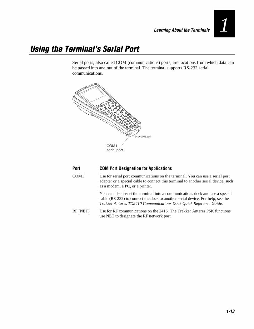
Serial ports, also called COM (communications) ports, are locations from which data canbe passed into and out of the terminal. The terminal supports RS-232 serialcommunications.
COM1serial port
241XU006.eps
Port COM Port Designation for Applications
COM1 Use for serial port communications on the terminal. You can use a serial portadapter or a special cable to connect this terminal to another serial device, suchas a modem, a PC, or a printer.
You can also insert the terminal into a communications dock and use a specialcable (RS-232) to connect the dock to another serial device. For help, see theTrakker Antares TD2410 Communications Dock Quick Reference Guide.
RF (NET) Use for RF communications on the 2415. The Trakker Antares PSK functionsuse NET to designate the RF network port.
Trakker Antares 241X Hand-Held Terminal User’s Manual Co de 39 Nugget
1-14
Using the Terminal’s ScreenYou can use the terminal’s screen to view data, run applications, monitor the terminal’sstatus, and for many other functions. The screen is a backlit LCD that is CGAcompatible and it has a maximum of 16 lines by 20 characters. The screen also supportsdouble-byte characters and user-programmable fonts.
Depending on the application, you can also use the viewport feature to move around afull 25 line by 80 character screen.
The Backlight key is built into the terminal’s keypad. You can use the Backlight key to:
• Turn the backlight on and off.
• Adjust the display contrast.
• Change the beep volume. For help, see “Understanding the Terminal’s AudioSignals” later in this chapter.
When you use this key to change the backlight, contrast, or beep volume, these changesare not saved permanently in flash memory.
To turn the backlight on and off
• Press .
Turn the backlight on to see the terminal’s screen more easily in dimly-lit environments.The backlight stays on for the length of time set in the Display Backlight Timeoutcommand as long as there is no keypad or scanning activity or until you press again.For more information, see “Display Backlight Timeout” in Chapter 8.
Note: You use the battery power at a faster rate with the backlight turned on.
To change the display contrast
• Press � .
Each time you press � , it makes the display contrast one level darker. There are eightcontrast levels. If the contrast is at the darkest level and you press � , the contrastchanges to the lightest contrast level.

Co de 39 Nugget Learning About the Terminals
1-15
1Understanding the Terminal’s Status LEDs
You can use the status LEDs to monitor the status of bar code scanning, of networkcommunications, of special keys, and of battery power. The status LEDs only flash orturn on to indicate the current status. The Battery LED is amber and all other LEDs aregreen. When the terminal is off, the LEDs are also off.
241XU007.eps
Good Read This LED turns on when you successfully scan a bar code label with thescanner or the input device that is connected to the terminal. This LED turns off aftertwo seconds.
User Defined This LED is user defined. You can program this LED to turn on and offfor any task or error within your application.
Network Connect This LED tells you if the 2415 is connected to your network. TheNetwork Connect status light may be off, blinking, or on.
LED Off LED Blinks LED OnTCP/IP Not connected. Nothing Connected to an
access point.
UDP Plus Not connected. Connected to anaccess point, butnot to a DCS 300.
Connected to aDCS 300.
When this LED is off, you are not connected to the network. Make sure the NetworkActivate command is enabled and that the terminal is configured correctly for your RFnetwork. Make sure that you are in range of an access point.
In a UDP Plus network, this LED is not instantaneously updated, but it does tell you thecommunications status the last time data was sent or received from the terminal.
Modifier This LED indicates that one of the modifier keys, such as ;, is active.When you press another key, the key combination is available to the application. TheModifier LED turns off unless the second key that you pressed is another modifier keythat is different from the first one that you pressed.
If Caps Lock is enabled, this LED remains on until you disable Caps Lock.
Battery This LED remains off when you have a charged battery pack in the terminal.The light turns on when there is a low battery charge and the terminal is on. When theterminal beeps once every 15 seconds, replace the battery pack with a charged batterypack or charge the battery pack as soon as possible.
Trakker Antares 241X Hand-Held Terminal User’s Manual Co de 39 Nugget
1-16
Understanding the Terminal’s Status BeepsThe terminal has a beeper that provides you with audio feedback as you use the terminal.For example, you hear a beep tone each time you enter or scan a valid command. Youcan change the beep volume to meet the needs of your working environment.
When you change the beep volume, you will also change the keyclick volume if theKeypad Clicker command is enabled. The keyclick is the sound that you hear when youpress a key on the terminal.
There are three ways to change the beep volume:
• Use the Backlight key (press ) on the keypad. Each time you press , itmakes the beep volume one level louder. On the 241X, there are three beep volumelevels including off. If the volume is at the loudest level and you press , thebeep volume is turned off. If you press again, the volume changes to thequietest level.
• Use the TRAKKER Antares 2400 Menu System. From the Main Menu, chooseConfiguration Menu, then Terminal Menu, and then Beeper.
• Use the Beep Volume command. For help, see “Beep Volume” in Chapter 8.
This table explains the purpose of each beep sequence you may hear.
Beep Sequence Description
High beep You entered valid data, you entered a valid command, theterminal decoded a label, or the terminal decoded the last row of atwo-dimensional bar code.
Three low beeps You entered or scanned an invalid command or data.
Four low beeps The terminal has booted and the power-on self test (POST) hasexecuted successfully.
Low beep, high beep,low beep, high beep
You have booted the terminal and the POST failed. For help, see“Problems While Operating the Terminal” in Chapter 4.
Click You have pressed a key and the Keypad Clicker command isenabled. To disable the keyclick, see “Keypad Clicker” in Chapter8. The terminal also clicks while you are scanning a two-dimensional (Code 16K or Code 49) bar code label.
Low beep (every 15seconds)
The battery pack is low. You need to replace or recharge thebattery pack. For help, see “Using the Terminal’s Battery Pack”later in this chapter.

Co de 39 Nugget Learning About the Terminals
1-17
1Connecting an Input Device to the Terminal
The terminal has an integrated I/O connector that lets you connect input devices to theterminal using special cables.
Intermec Input Device Cable Part No.
1280B wand
1550B laser scanners with software v1.9 or later 069813
1551B laser scanners with software v1.1 or later 069814
You can either use the special cable for the input device or you can use a standard cablewith special adapter cables (Part No. 069591 or Part No. 069589). For an updated list ofavailable input devices,contact your local Intermec representative.
Once you have connected the input device to the teminal, you may want to configure theScanner Selection command to optimize the scanning performance. For moreinformation, see “Scanning Options” later in this chapter.

Trakker Antares 241X Hand-Held Terminal User’s Manual Co de 39 Nugget
1-18
Using the Terminal’s Battery Pack
WarningThe lithium-ion battery pack that is used in this device may present a fire or chemicalburn hazard if it is mistreated. Do not disassemble it, heat it above 100ºC (212ºF) orincinerate it.
AvertissementLe paquet de piles d’ions de lithium qui est utilisé dans cet appareil peut presenter unrisque feu ou un risque chimique de brûlure s’il est maltraité. Il ne faut pas ledésassembler, le réchauffer à une température plus élevée que 100o C (212o F) oul’incinérer.
The main power source for the terminal is a lithium-ion battery pack. When you changethe battery pack, a backup power source maintains the terminal status, memory, and real-time clock for at least 15 minutes. Follow these tips to get the best battery performanceand life possible:
• Keep a spare, fully charged battery pack on hand.
• Keep a charged battery pack installed in the terminal to maximize the backup powersource’s life and so you can continue to operate the terminal without interruption.
• If the terminal turns off due to a low battery, do not turn the terminal back on.Replace or charge the battery pack before you continue using the terminal.
• Do not press : when the battery pack is removed.
Replace the battery pack with Part No. 069428 or Part No. 069429 only. Contact yourlocal Intermec sales representative for a replacement battery pack. DISPOSE OF USEDBATTERY PACKS PROMPTLY. KEEP THEM AWAY FROM CHILDREN.
Determining When the Battery Pack is LowThe battery pack is the main power source for the terminal and it charges the backuppower source, when required. If the main battery charge goes low, you need to replace itwith a charged battery pack or charge the battery pack as soon as possible.
There are two ways to find out if the battery pack is low:
• The Battery LED turns on and the terminal beeps once every 15 seconds.
• Check the status of the battery pack using the Battery/PIC Status diagnostic test. Forhelp, see Chapter 6, “Running Diagnostics.”
Note: While the battery is charging, do not use this diagnostic test to determine whenthe battery is fully charged. To determine when the battery is fully charged, use thestatus LEDs on the battery chargers or communications dock.

Co de 39 Nugget Learning About the Terminals
1-19
1Charging the Battery PackYou can charge the battery pack using any of these Trakker Antares accessories:
• Battery charger (2-pack or 4-pack)
• Communications dock connected to an external power supply
The charger uses a charging method that maximizes battery life. Charge the battery packuntil the Charge Status LED turns green to ensure that it is fully charged. The standardbattery pack takes about 2 hours to charge and the high performance battery pack takesabout 4 hours. For help, see the instruction sheet that ships with your charger.
You can also charge the battery pack while continuing to use the terminal by using acommunications dock that is connected to a power supply. For help, see the TrakkerAntares TD2410 Communications Dock Quick Reference Guide.
Installing the Battery Pack
1. Hold the battery pack with the flat side facing the terminal. Orient the battery pack asshown in the illustration.
2. While holding the battery pack at an angle, hook the bottom edge of the battery packinto the notches on the terminal.
241XU008.eps
3. Lower the battery pack toward the terminal until the battery pack clicks into place.

Trakker Antares 241X Hand-Held Terminal User’s Manual Co de 39 Nugget
1-20
Removing the Battery Pack
CautionRemoving the battery pack while the terminal is on may cause loss of data.
ConseilNe détachez pas le paquet de piles pendant que le terminal est actif car cela pourraitentraîner la perte de données.
1. Press : to turn off the terminal.
2. While holding the terminal in one hand, grasp the battery pack on both sides.
3. Pull down on the battery release latch to release the battery pack and remove thebattery pack.
241XU009.eps
Battery release latch

Co de 39 Nugget Learning About the Terminals
1-21
1Managing Battery PowerTo maximize the life of the battery pack, use these power management features.
Situation Ways to Save Battery Power
You are operating the terminaland the Battery LED turns on.
Press : to turn off the terminal. Remove the batterypack and insert another fully charged battery pack.You must insert another fully charged battery packwithin 15 minutes of removing the old battery pack oryou may lose data.
Or, if you want to continue using the terminal and youdo not have another battery pack, insert the terminalinto a communications dock. The dock must beconnected to an external power supply.
You are not using the terminal for 5minutes or longer.
Make sure the Battery LED is not on. Press : to turnoff the terminal.
Or, use the Automatic Shutoff feature. Automaticshutoff turns off the terminal when there is no activityon the terminal for the length of time you set. Forhelp, see “Automatic Shutoff” in Chapter 8.
You are going to store theterminal for more than a day.
Save your data and end your terminal session tominimize the risk of data loss. Press : to turn off theterminal. Insert a fully charged battery pack beforeyou store the terminal.

Trakker Antares 241X Hand-Held Terminal User’s Manual Co de 39 Nugget
1-22
Defining the Terminal’s DrivesThe terminal comes with two flash drives and a configurable RAM drive. On the 2410you can purchase an optional extended storage drive. On each drive, filenames arecustomer defined using eight characters with a three-character extension. You cannotdefine any subdirectories.
Drive D or font set
Drive C
Drive E
Drive G 241XU010.eps
Drive C
Drive C
Drive D or font set
Drive E
2415 2410
Optional 2MB flash drive
Optional 2MB flash drive
750K flash drive
750K flash drive
256KconfigurableRAM drive
256K configurableRAM drive
Optional 2MB or 4MB extended storage drive
Drive C is a 2MB flash drive. You can use up to 750K of this flash drive to store up to128 files on drive C. Applications must be stored on drive C. You use standard ANSI Clibrary interface definitions to access the information on this drive.
Drive D or font set is an optional 2MB of flash memory. If you order the 4MB flashmemory option, you can configure 2MB as drive D. Use this flash drive to store largelookup tables and data files. You can store up to 128 files. You can also order the 4MBflash memory option to come pre-loaded with an Asian font set. To configure this flashmemory, see “Flash Memory Configuration” in Chapter 8.
Drive E is a configurable RAM drive (up to 256K). The contents of this drive are erasedwhen you boot or reset the terminal. You use standard ANSI C functions to access thefiles on this drive. You can store up to 128 files on drive E. By default, the RAM drive isnot configured and the memory is available for programmable (Malloc) memoryallocations. To configure the RAM drive, see “RAM Drive Size” in Chapter 8.
Drive G is an optional 2MB or 4MB extended storage drive that is only available on the2410. Use this PC card drive to store large lookup tables and data files. You can store upto 128 files on drive G.

Co de 39 Nugget Learning About the Terminals
1-23
1On the terminals, applications are customer defined. You have 512K total RAM that youcan use for the application execution space. You can also configure this RAM to be theRAM drive (up to 256K). The remaining RAM is the Malloc/free memory pool.
Applicationexecution space
+ RAM drive(drive E)
+ Malloc/freememory pool
= 512K RAM
Using the Terminal’s Scanner
WarningDo not look directly into the window area or at a reflection of the laser beam whilethe laser is scanning. Long-term exposure to the laser beam can damage your vision.
AvertissementNe regardez pas directement la réflexion d’un rayon laser ou dans la fenêtre du laserlorsque celui-ci est en opération. Si vous regardez trop longtemps un rayon laser, celapeut endommager votre vue.
You use the scanner to scan and enter bar code data. When you press the Scan button,the scanner emits a beam of laser light that is visible on a bar code label as you scan it.The terminal decodes the bar code label and enters the data or command you scanned.
When you unpack the terminal, these three bar code symbologies are enabled:
• Code 39
• Code 128
• UPC/EAN
If you are using bar code labels that are encoded in another symbology, you need toenable that symbology on the terminal. For help, find the symbology in Chapter 8,“Configuration Command Reference.”
Note: The Scan button on the keypad does not activate the tethered input device that maybe connected to the terminal.
Trakker Antares 241X Hand-Held Terminal User’s Manual Co de 39 Nugget
1-24
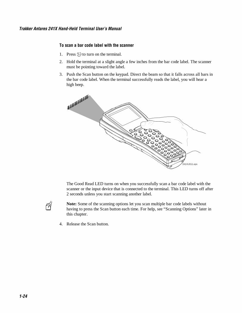
To scan a bar code label with the scanner
1. Press : to turn on the terminal.
2. Hold the terminal at a slight angle a few inches from the bar code label. The scannermust be pointing toward the label.
3. Push the Scan button on the keypad. Direct the beam so that it falls across all bars inthe bar code label. When the terminal successfully reads the label, you will hear ahigh beep.
*B02418*
241XU011.eps
The Good Read LED turns on when you successfully scan a bar code label with thescanner or the input device that is connected to the terminal. This LED turns off after2 seconds unless you start scanning another label.
Note: Some of the scanning options let you scan multiple bar code labels withouthaving to press the Scan button each time. For help, see “Scanning Options” later inthis chapter.
4. Release the Scan button.
Co de 39 Nugget Learning About the Terminals
1-25
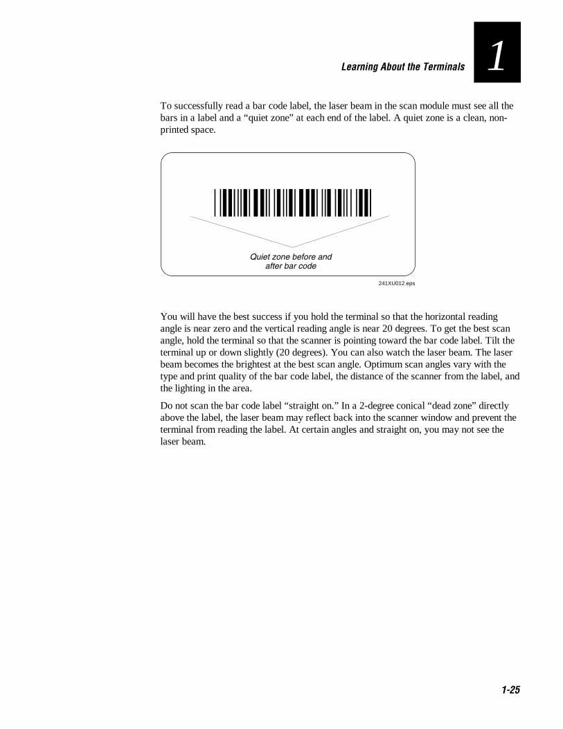
1To successfully read a bar code label, the laser beam in the scan module must see all thebars in a label and a “quiet zone” at each end of the label. A quiet zone is a clean, non-printed space.
*NANCY*
Quiet zone before andafter bar code
241XU012.eps
You will have the best success if you hold the terminal so that the horizontal readingangle is near zero and the vertical reading angle is near 20 degrees. To get the best scanangle, hold the terminal so that the scanner is pointing toward the bar code label. Tilt theterminal up or down slightly (20 degrees). You can also watch the laser beam. The laserbeam becomes the brightest at the best scan angle. Optimum scan angles vary with thetype and print quality of the bar code label, the distance of the scanner from the label, andthe lighting in the area.
Do not scan the bar code label “straight on.” In a 2-degree conical “dead zone” directlyabove the label, the laser beam may reflect back into the scanner window and prevent theterminal from reading the label. At certain angles and straight on, you may not see thelaser beam.

Trakker Antares 241X Hand-Held Terminal User’s Manual Co de 39 Nugget
1-26
Scanning OptionsYou can set several configuration commands to configure the scanner to meet your needs.For help understanding the scanner configuration commands, see Chapter 8,“Configuration Command Reference.” The commands that are available are:
Decode Security Defines the security level to use when decoding bar codes. When youselect a lower decode security level, the terminal can decode bar codes with poorer printquality.
Scan Ahead Lets you scan a number of bar code labels at one time. The labels are heldin a stack until the terminal can process the data.
Scanner Mode Defines how the scanner operates when you press the Scan button oractivate a tethered input device. In One-Shot mode, the laser turns on and stays on untilyou release the button or scanner trigger, or a label is decoded. In Automatic mode, youcan continuously scan bar code labels without having to release the button or scannertrigger between labels.
Scanner Redundancy Defines the number of scans (voting) the scanner takes of thesame label. When set, voting requires the terminal to decode the same bar code labelmultiple times during a single scanner event, and compare the decoded information for amatch before signaling a good read.
Scanner Selection Identifies the type of scanner that is on the terminal or that you haveconnected to the terminal. The terminal can optimize the scanning performance by usingthe scanner you define in this command. If you have a long-range, high-density, or high-visibility scanner, this parameter lets you configure the spotting beam.
Scanner Timeout Defines the maximum length of time the scanner stays on each timeyou press the Scan button or activate the tethered input device.
Scanner Trigger Lets you set the triggering to level or edge triggering. With leveltriggering, you activate the scanner and the laser turns on and stays on until you releasethe Scan button or the trigger on a tethered input device. In edge triggering, you activatethe scanner and the laser turns on and stays on until you activate the scanner a secondtime, or the scanner timeout turns it off.

Co de 39 Nugget Learning About the Terminals
1-27
1Using the Terminal for the First Time
Before you can use the terminal for the first time, you must perform certain steps, such assetting the time and date. You can find this information throughout this user’s manual.However, if you want to start using the terminal immediately, see the Trakker Antares241X Hand-Held Terminal Getting Started Guide.
To use the terminal for the first time
1. Unpack the terminal and documentation.
2. Charge and install the battery pack (sold separately). For more information onbatteries, see “Using the Terminal’s Battery Pack” earlier in this chapter.
3. Press : to turn on the terminal. For more information on the keypad, see “Using theKeypad” earlier in this chapter.
4. (Optional) Set the time and date. For help using the TRAKKER Antares 2400 MenuSystem, see “Configuring the Terminal With the Menu System” in Chapter 3.
5. Configure the serial port parameters. For more information, see “Connecting theTerminal to a Wired Network” in Chapter 2.
6. (2415 only) Configure the RF parameters. For more information, see “Connectingthe 2415 to an RF Network” in Chapter 2.
7. Enable the bar code symbologies that you want to be able to scan. For moreinformation, see Chapter 8, “Configuration Command Reference.”
8. Exit the menu system and save your configuration changes to flash memory. Forhelp, see “Exiting the Menu System” in Chapter 3.
When you are done with these steps, the default application or TE application that isloaded on your terminal will start. You are ready to use the terminal.

1-28
Co de 39 Nugget
Operating the Terminals in a Network
2

Co de 39 Nugget
4-2

Co de 39 Nugget Operating the Terminals in a Network
2-3
2This chapter explains how the terminals fit into a data collection network and whatparameters to configure for your serial or RF network.
How the Terminals Fit Into Your NetworkThe Trakker Antares 2410 and 2415 terminals are versatile hand-held terminals that youcan easily add to your network or distributed data collection system. You use theseterminals as end devices in your wired or RF network.
The terminals have a serial port that lets them transmit data to and receive data from ahost computer or PC via RS-232 serial communications. The terminal can communicatewith the RS-232 device using one of these protocols: Binary, Configurable, MasterPolling, Polling Mode D, or Point-to-Point.
Note: If you insert the terminal into a communications dock, you can transmit data to andreceive data from a host computer or PC via RS-232 serial communications.
241Xs in a Wired Network
File serverMainframe
Terminals
241XU014.eps
PC
241X inCommunications dock
hardwired to PC
Ethernet
RS-2324
8

Trakker Antares 241X Hand-Held Terminal User’s Manual Co de 39 Nugget
2-4
You can also use the serial port to connect to a 900 MHz RF network via the 9189 RFGateway. The terminal communicates with the 900 MHz RF network using Polling ModeD protocol.
2410s in a 900 MHz RF Network
RS-485
RS-232
DCS 300
J2010
J20509189
900 MHz
241XU016.eps
Host
9181
241X
Tab
4
8

Co de 39 Nugget Operating the Terminals in a Network
2-5
2In a UDP Plus network, 2415s communicate with a host computer through the DCS 300.The DCS 300 translates UDP Plus packets on the RF network into TCP/IP packets onthe wired network and vice versa. The access point acts as a bridge between the wirednetwork and the RF network.
2415s in a UDP Plus Network
Ethernet
Access point
2415s
241XU017.eps
Host
DCS 300
Tab
4
8
Tab
4
8
Tab
4
8
Tab
4
8

Trakker Antares 241X Hand-Held Terminal User’s Manual Co de 39 Nugget
2-6
In a TCP/IP network, 2415s communicate with a host computer directly using TCP/IPfor the RF protocol. The access point acts as a bridge between the wired network and theRF network.
2415s in a TCP/IP Direct Connect Network
Ethernet
Access point
2415s
241XU019.eps
Host
Tab
4
8
Tab
4
8
Tab
4
8
Tab
4
8
Co de 39 Nugget Operating the Terminals in a Network
2-7
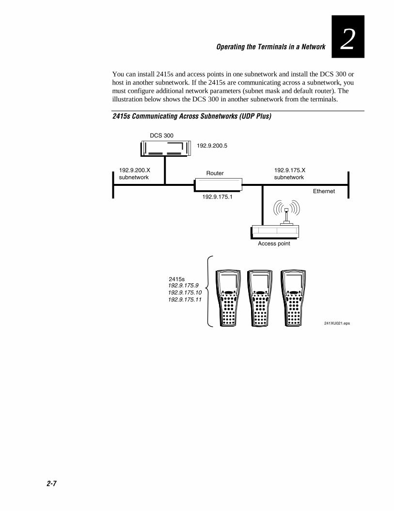
2You can install 2415s and access points in one subnetwork and install the DCS 300 orhost in another subnetwork. If the 2415s are communicating across a subnetwork, youmust configure additional network parameters (subnet mask and default router). Theillustration below shows the DCS 300 in another subnetwork from the terminals.
2415s Communicating Across Subnetworks (UDP Plus)
Access point
192.9.200.Xsubnetwork
192.9.175.Xsubnetwork
2415s
Ethernet
Router
241XU021.eps
192.9.175.1
192.9.200.5
192.9.175.9192.9.175.10 192.9.175.11
DCS 300
Tab
4
8
Tab
4
8
Tab
4
8

Trakker Antares 241X Hand-Held Terminal User’s Manual Co de 39 Nugget
2-8
In a UDP Plus network, you can install 2415s, access points, and DCS 300 as shown inthe next illustration. All the terminals and access points in this illustration communicatewith the DCS 300 at IP address 192.9.175.7. If you are using 21XX Universal AccessPoints (UAPs), a terminal can roam across subnetworks.
If you are using the 011X Access Points, a terminal can only communicate with theaccess points that are in the same subnetwork. In this illustration, if you substituted the011X Access Points for the UAPs, the terminal at IP address 192.9.200.5 could notcommunicate with DCS 300 on the 192.9.175.X subnetwork.
2415s in Multiple Subnetworks (UDP Plus)
21XX UAP 21XXUAP21XX UAP
RouterEthernet
192.9.200.Xsubnetwork
192.9.175.Xsubnetwork
2415s192.9.175.10192.9.175.11192.9.175.12
241XU023.eps
2415s192.9.200.5, 192.9.200.6
192.9.175.7DCS 300
Tab
4
8
Tab
4
8
Tab
4
8
Tab
4
8
Tab
4
8

Co de 39 Nugget Operating the Terminals in a Network
2-9
2In a TCP/IP network, you can install the 2415s and access points as shown in theillustration below. All the terminals and access points in this illustration communicatewith the host at IP address 192.9.175.7. If you are using UAPs, a terminal can roamacross subnetworks.
If you are using the 011X Access Points, a terminal can only communicate with accesspoints that are in the same subnetwork. In this illustration, if you substituted the 011XAccess Points for the UAPs, the terminal at IP address 192.9.200.5 could notcommunicate with the host on the 192.9.175.X subnetwork.
2415s in Multiple Subnetworks (TCP/IP)
21XX UAP 21XX UAP21XX UAP
RouterEthernet
Host
192.9.200.Xsubnetwork
192.9.175.Xsubnetwork
2415s192.9.175.10192.9.175.11192.9.175.12
241XU026.eps
2415s192.9.200.5, 192.9.200.
192.9.175.7
Tab
4
8
Tab
4
8
Tab
4
8
Tab
4
8
Tab
4
8

Trakker Antares 241X Hand-Held Terminal User’s Manual Co de 39 Nugget
2-10
Connecting the Terminal to a Wired NetworkThe terminals have a serial port (COM1) that lets them transfer data to and receive datafrom another device via RS-232 serial communications. If you insert the terminal into acommunications dock, you can transmit data to and receive data from a host computer orPC via RS-232 serial communications.
Before you can use serial communications, you must perform these steps:
1. Connect COM1 to the serial port of the other device. For help, see “Using theTerminal’s Serial Port” in Chapter 1.
Or, insert the terminal into the communications dock. For help, see the TrakkerAntares TD2410 Communications Dock Quick Reference Guide.
2. Choose a communications protocol. For help, see the next section “Choosing aCommunications Protocol.”
3. Configure the serial port parameters. For help, see the Chapter 3, “Configuring theTerminals.”
Once the terminal is connected and configured, you can transfer data between theterminal and the device that is connected to the serial port. For help transferring files, seeChapter 4, “Using Custom Applications.”
Choosing a Communications ProtocolOnce the terminal is connected to a host computer, PC, or other serial device, you areready to choose a communications protocol and set its parameters. Communicationsprotocols determine exactly how data is transmitted between the terminal and theconnected serial device. Both the terminal and the connected device must use the sameprotocol and parameter settings.
The terminal uses a communications protocol and XMODEM or YMODEM to handle datacommunications through the serial port. The terminal’s built-in file operations useXMODEM or YMODEM for file transfer.
The terminal can communicate in these five protocols:
• Binary
• Configurable
• Master Polling
• Point-to-Point
• Polling Mode D
Co de 39 Nugget Operating the Terminals in a Network
2-11
2Binary ProtocolBinary protocol has no protocol. Characters are sent and received without being altered.The Data Link Escape character (DLE) is not inserted before any character. DLEcharacters are not stripped out of the incoming data stream and no protocol characters,such as EOM or SOM, are added. Binary protocol supports CTS/RTS flow control only.
Here are the serial port parameters you can define:
• Baud rate
• Data bits
• Parity
• Stop bits
• Flow control
Configurable ProtocolConfigurable protocol is based on Intermec’s Polling Mode D protocol except that youhave the option to change some of the serial port protocol parameters or remove specificevents from the protocol, such as Poll or Handshake.
Here are the serial port parameters you can define:
• Baud rate
• Data bits
• Parity
• Stop bits
• Flow control
• EOM (End of Message)
• Configuration commands via serial port
• LRC
• SOM (Start of Message)
• Handshake
• Poll (Polling)
• Timeout Delay
This protocol uses EOM to determine the serial communications mode. When EOM isdisabled, the terminal communicates in Character mode. The terminal processes eachcharacter. Character mode supports both XON/XOFF and CTS/RTS flow control.
When EOM is enabled, the terminal communicates in Frame mode. When a terminalsends a packet, it adds protocol characters. When a terminal receives a packet, it stripsany protocol characters before it sends the information to the terminal application. Framemode supports both XON/XOFF and CTS/RTS flow control. In Frame mode, you canalso define these serial port parameters: Configuration commands via serial port, LRC,SOM, Handshake. Once Handshake is enabled, you can define poll and timeout delay.

Trakker Antares 241X Hand-Held Terminal User’s Manual Co de 39 Nugget
2-12
Master Polling ProtocolMaster Polling Mode D protocol requires the terminal to ask the downline serial devicefor data it may have (polling) and to request to send data to the serial device (selecting).There is no automatic polling, so your application must poll periodically for data.
Before each transmit operation, the terminal issues the SEL sequence for the deviceaddressed and sends the data if an acknowledge is received. Before each receiveoperation, the terminal issues a POL sequence and waits for data or the RES character(no data is available to send).
Here is the serial port parameter you can define:
• Baud rate
Point-to-Point ProtocolPoint-to-Point protocol is not directly supported on the terminals. However, you cansimulate this protocol by setting the protocol to Configurable and configuring theseparameters:
• Baud rate
• Data bits
• Parity
• Stop bits
• Flow control
• EOM (Set EOM1 to \x0D, which is <CR> and set EOM2 to \x0A, which is <LF>)
• LRC (Disable)
• Handshake (Disable)
If you use this protocol, you cannot configure values for intercharacter delay, turnarounddelay, and timeout delay. This protocol supports CTS/RTS flow control only.
Polling Mode D ProtocolPolling Mode D protocol requires a host application to ask the terminal for data it mayhave (polling) and to request to send data to the terminal (selecting). This protocolimplements the user interface through reader commands. Polling Mode D uses an RS-232interface. Use this protocol if you want to connect to a 900 MHz RF network via the9189 RF Gateway. This protocol supports XON/XOFF and CTS/RTS flow control.
Here are the serial port parameters you can define:
• Baud rate
• Flow control

Co de 39 Nugget Operating the Terminals in a Network
2-13
2Connecting the 2415 to an RF Network
CautionMake sure all components with antennas are at least 30 centimeters (1 foot) apartwhen power is applied. Failure to comply could result in equipment damage.
ConseilAssurez-vous que la distance entre tous les éléments avec antennes soit d'au moins30 centimètres (un pied) avant de faire la connexion avec l'alimentation électrique,faute de quoi vous risquez d'endommager votre installation.
Before you can begin using the 2415 to collect data, you need to install and configureeach device in the RF network by performing these steps:
1. Plan and prepare your network. For help, see “Planning the Network Connection” inthe next section.
2. (UDP Plus network only) Configure the DCS 300. For help, see “Configuring theDCS 300” later in this chapter and the DCS 300 System Manual (Part No. 067296).
3. Configure the access points. For help, see “Configuring the Access Points” later inthis chapter and your access point user’s manual.
4. Configure each terminal. For help, see “About the Network Parameters” later in thissection and Chapter 3, “Configuring the Terminal.”
When you begin using the 2415, you must understand how to use the LEDs to monitorthe RF communications. For help, see “Monitoring RF Communications Using the StatusLEDs” later in this chapter.
Planning the Network ConnectionTo use the 2415 in the RF network, you need these minimum requirements:
• (UDP Plus network) DCS 300
• Access point
When you first consider purchasing a wireless data collection system, an Intermecrepresentative works with you to perform a site survey at your facility. The site surveyanalyzes the range of radio frequency devices in your facility and determines theplacement of the access points. The site survey ensures that the coverage of each accesspoint overlaps to provide uninterrupted wireless access at any location within thebuilding.
You must work with your network administrator to plan and assign the networkparameters for each device in the RF network. For example, you must assign and set theIP address for each access point and each terminal. If you are using a UDP Plus network,you must also assign an IP address to the DCS 300.

Trakker Antares 241X Hand-Held Terminal User’s Manual Co de 39 Nugget
2-14
Configuring the DCS 300The DCS 300 supports and manages communications with other devices in the UDP Plusnetwork. When you install and configure the DCS 300, you identify the host computer(s)and 2415s in your network. The terminals communicate using a reliable RF protocol(UDP Plus) to the DCS 300. The DCS 300 translates UDP Plus to a reliable wiredprotocol (TCP/IP) and sends the data on to the host. For more information, see theDCS 300 System Manual (Part No. 067296).
Note: You can use a 2415 that is communicating using UDP Plus and the DCS 300 in apass-through network. You establish a direct TCP/IP socket connection from the 2415 tothe host through the server.
To have the 2415 communicate with the DCS 300, you must configure these parameterson the server:
• Define the host communications parameters, which includes the physical connection(network adapter cards) to the host.
• Configure the UDP Plus network.
• Assign an IP address to each 2415. This IP address matches the IP address that youwill set on your terminals.
• Enable all 2415 terminals.
• Define the host environment parameters, which includes configuring hosts forterminal emulation, peer-to-peer applications, or screen mapping sessions.
To do screen mapping on the DCS 300, you must also:
• Create the script file using the Script Builder Tool on the server.
• Create an application using EZBuilder and download it to the 2415.
Configuring the Access PointThe access point acts as a bridge that provides communications between the wirednetwork and the RF (UDP Plus or TCP/IP) networks. Once the network is configured,you can collect data anywhere within range of the access points. When you move out ofrange of one access point, the 2415 automatically searches for other access points tocontinue the network connection. To ensure that the roaming 2415 will always have aconnection available, the radio coverage of each access point must overlap. For morehelp, see your access point user’s manual.
If you go out of range of all access points in the network, the data is stored in theterminal’s radio buffer. The Network Status LED turns off. You can continue to collectdata until the radio buffer is full. When the buffer is full, the application displays acommunication timeout status. When you move back into range and networkcommunications are re-established, the data in the radio buffer is transmitted to theaccess point and you can once again transmit data.
Co de 39 Nugget Operating the Terminals in a Network
2-15
2In a TCP/IP direct connect network with a 2415 running a terminal emulationapplication, the application may disconnect from the host if you remain out ofcommunications range too long or if the host sends “Keep Alive” messages while theterminal is in Suspend mode. You may need to restart the application and log back intothe host to re-establish a terminal emulation session. For help, see Chapter 5,“Troubleshooting and Maintaining the Terminals.” In a UDP Plus network, the session ismaintained any time the terminal is out of range or in Suspend mode.
All RF devices must contain the same radios (2.4 GHz OpenAir or IEEE 802.11 DS) tocommunicate with each other. Depending on the radio that is in the devices, you must setcertain parameters that match on the 2415s and on the access points.
2.4 GHz OpenAir NetworkIf the 2415s and the access points have 2.4 GHz OpenAir radios, you must know thevalue of these parameters on the access points that you want to communicate with:
• RF domain
• (Optional) RF security identification (ID)
The values that are set for these parameters must match the values on each terminal.Each access point is configured with a different channel/subchannel combination.
IEEE 802.11 DS NetworkIf the 2415s and the access points have IEEE 802.11 DS radios, you must know thevalue of this parameter on the access points that you want to communicate with:
• Network name
The value that you set for this parameter must match the value on each terminal.However on the terminal, you can set this parameter to “any” or “ANY” and the terminalwill be able to communicate with any access point that has the same radio and is withinrange. This parameter is case-sensitive.
You can also set these parameters on both the access points and the 2415s:
• Reservation enable
• Reservation
• Transmit rate
• AP density
The values that you set for these parameters do not have to match the values on eachterminal. However on the terminal, you may improve network performance if these valuesmatch.

Trakker Antares 241X Hand-Held Terminal User’s Manual Co de 39 Nugget
2-16
About the Network ParametersWhen you install the 2415 in a network, you must configure the network parameters thatcontrol how the terminal communicates in the network. The set of network parametersyou must configure depends on whether you install the terminal on the same subnetworkas the DCS 300 or host (TCP/IP), or if you install the terminal on a different subnetwork.
Here are the network parameters you must define:
• Network activate
• (UDP Plus) Controller IP address
• (TCP/IP) Host IP address
• Terminal IP address
• Network port
• (DCS 300 or host on different subnetwork) Default router
• (DCS 300 or host on different subnetwork) Subnet mask
For help understanding these parameters and their syntax, see Chapter 8, “ConfigurationCommand Reference.”

Co de 39 Nugget Operating the Terminals in a Network
2-17
2Monitoring RF Communications Using the Status LEDs Once you have configured the devices in the RF network, you can begin using theapplication on the 2415 to collect and transmit data via RF communications. If theterminal is communicating with your host computer, the terminal will connect and beginrunning the application that shipped on the terminal.
As you use the 2415 to collect data, the Network Connect status LED may light or blinkto help you monitor RF and network communications on the terminal
LED Off LED Blinks LED OnTCP/IP Not connected. Connected to an
access point, but notto a host.
Connected to a host.
UDP Plus Not connected. Connected to anaccess point, but notto a DCS 300.
Connected to aDCS 300.
If you are not connected to an access point
1. Verify that the Network Activate command is enabled.
2. Verify that the access points are turned on and operating.
3. Verify that you are using the terminal within the range of an access point. Trymoving closer to an access point to re-establish communications.
4. Verify that the terminal is configured properly for RF communications.
5. You may have a problem with the radio. Contact Intermec Technical Support.
If you are connected to an access point, but not to a host or a DCS 300
1. Verify that the terminal has the correct host IP address or controller IP address.
2. Verify that the DCS 300 or host has been configured properly. Verify that theDCS 300 is turned on and that data collection is started.
Trakker Antares 241X Hand-Held Terminal User’s Manual Co de 39 Nugget
2-18
About Network Connectivity and ProtocolsThe Trakker Antares 2410 and 2415 terminals are hand-held data collection terminalswith network support. The terminals communicate with a host computer or other serialdevice through the terminal’s serial port. The 2415 also communicates with a host eitherthrough the DCS 300 or directly through the access points. The access point acts as abridge between the wired network and the RF network.
In a UDP Plus network, the terminal communicates through an access point via theDCS 300 to a host on a wired network. In a TCP/IP network, the terminal communicatesthrough the access point directly to a host on a wired network.
The communications protocol stack for the terminal is developed using the Open SystemsInterconnection (OSI) seven layer model. The illustration on the next page shows how the2.4 GHz RF network and RS-232 serial port map into the OSI model.
The terminal applications including terminal emulation and screen mapping are on top ofthe protocol stack. Intermec provides a terminal communications API (applicationprogram interface) to interface to the protocol stack. The API provides a commoninterface to these Intermec value-added protocols:
• Terminal Message Format (TMF) is an Intermec proprietary protocol that is used toroute data and network management messages between applications on the terminaland peer tasks on the DCS 300 or host.
• UDP Plus is an Intermec protocol built on top of the User Datagram Protocol (UDP).It maximizes the performance of wireless (RF) and hardwired networks and providesrobust data communications.
• Trivial File Transfer Protocol (TFTP) allows efficient file exchange between theterminal and the DCS 300 or host.
• Configurable Serial Port (CSP) protocol allows efficient file exchange between theterminal and the host through RS-232 serial communications. The terminal useseither the XMODEM or the YMODEM protocol to transfer files via reader commands.
• Network management provides network access to the terminal configuration, status,and statistics. Network management uses the Terminal Message Format to receiveand send messages.
The remaining layers in the protocol stack are a series of standard protocols that interfacewith the drivers and hardware needed to support the RF network and RS-232 serialcommunications.

Co de 39 Nugget Operating the Terminals in a Network
2-19
2Trakker Antares Terminal Protocol Stack and the OSI Model
Terminal Message
Format (TMF)
Serialport
driver
Serialport
Wired
Network
UDP Plus
Configurable
serial port
protocol
Application
OSI Layers
Presentation
Session
Transport
Network
Data Link
Physical
Communications API and additions
Trivial File
Transfer Protocol
(TFTP)
UDP
TCP
ICMP, IP, and ARP
2.4 GHz RF protocol driver
2.4 GHz radio
RF Network
Network
management
TRAKKER Antares 241X
applications
241XU028.eps

Trakker Antares 241X Hand-Held Terminal User’s Manual Co de 39 Nugget
2-20
The terminals use these protocols:
Layer Protocol Description
Physical 2.4 GHz radio
Serial Port
Provides spread spectrum radio signal control.
Provides serial communications.
Data Link 2.4 GHz RF protocoldriver
Provides RF media access control. The default hardwiredmedia access control (MAC) protocol used with TCP/IPsupports the Ethernet II standard.
Serial port driver Provides serial communications control that uses CSP and thestandard XMODEM or the YMODEM protocol for datatransfer.
Network ICMP, IP, and ARP The Internet Control Message Protocol (ICMP) complies withthe standard outlined in RFC 826.
The Internet Protocol (IP) complies with the standardoutlined in RFC 791.
The Address Resolution Protocol (ARP) complies with thestandard outlined in RFC 826.
Transport UDP The User Datagram Protocol (UDP) complies with thestandard outlined in RFC 768.
TCP Transmission Control Protocol (TCP) complies with thestandard outlined in RFC 793.
Session and Presentation UDP Plus UDP Plus is an Intermec proprietary session layer protocolbuilt on UDP. The UDP Plus session layer provides theseservices:
• guaranteed delivery• duplicated message removal• link connection and status management• network error recovery• congestion control• device error detection
TFTP Trivial File Transfer Protocol (TFTP) allows efficient fileexchange between the terminal and the DCS 300 or host.TFTP complies with the standard outlined in RFC 1350.
Presentation and Application TMF Terminal Message Format is an Intermec proprietary protocolthat is used to route data, configuration, and networkmanagement messages between applications on the terminaland peer tasks on the DCS 300 or host.

Co de 39 Nugget
Configuring the Terminals
3

Co de 39 Nugget
3-2
Co de 39 Nugget Configuring the Terminals
3-3
3This chapter explains the different methods that you can use to configure theterminals. It also explains how to transfer files in a TCP/IP network, how to saveconfiguration changes to flash memory, and how to restore the default configuration.
How to Configure the TerminalYou can customize many operating characteristics of the Trakker Antares 2410 and 2415terminals, such as the volume of their audio signals and the bar code symbologies theydecode. These characteristics are controlled by configuration parameters. The values youset for the configuration parameters determine how the terminal operates. To learn abouteach configuration parameter, see Chapter 8, “Configuration Command Reference.” Youcan configure the terminals by using any of these methods:
Use the TRAKKER Antares 2400 Menu System Using menus and screens, theTRAKKER Antares 2400 Menu System, which is on every terminal, lets you view thecurrent configuration and change the configuration parameters.
Scan bar codes You can change the terminal’s configuration parameters by scanningCode 39 or Code 93 bar code labels that contain configuration commands. This method isa fast, easy way to change the terminal’s configuration. You can scan the bar code labelsin this manual, or you can create your own bar code labels.
Send commands through the serial port You can change the terminal’s configurationparameters by sending commands from a host computer or PC that is connected to theterminal’s serial port.
Send commands through the RF port (2415 only) You can change the terminal’sconfiguration parameters by sending commands from a DCS 300 or a host application.This method lets you configure one or more terminals at the same time.
About the ConfigurationsThe terminal uses three configurations: current, active, and default. Having separatecurrent and active configurations lets you control the active configuration while lettingeach operator make some changes to the current configuration, such as scanning a barcode to change the beep volume.
Current This configuration, also called the runtime configuration, uses theconfiguration that is saved in RAM. When you change a parameter by using the menusystem, by scanning a bar code, by sending it from a host application, or by sending itfrom the DCS 300, the terminal updates the current configuration. The changes to thecurrent configuration are lost when you boot or reset the terminal.
Active When you update the flash memory, the terminal copies the currentconfiguration to the active configuration. The active configuration is the configurationthat the terminal uses when you boot or reset the terminal.
Default This configuration is the factory default configuration. You may want torestore the default configuration. For help, see “Restoring the Terminal’s DefaultConfiguration” later in this chapter.

Trakker Antares 241X Hand-Held Terminal User’s Manual Co de 39 Nugget
3-4
Configuring the Terminal With the Menu SystemThe TRAKKER Antares 2400 Menu System is a menu-driven application that lets youconfigure the terminal, manage files, view system information, and run diagnostics. Youcan access the TRAKKER Antares 2400 Menu System while running any application.
When you are using the menu system, you may not see a parameter until you set a valuefor another key field. For example, EOM is a key field when you configure theConfigurable protocol. That is, several fields are invalid (do not appear) until you enableEOM. You also may not see a parameter if your terminal does not support a feature.
To access the TRAKKER Antares 2400 Menu System
• Press � 8 0 � ) or press � 8 � � � or scan this bar code label:
Note: You must press the 8 (Left Enter) key in this key sequence.
Enter Test and Service Mode
*..-.**..-.*
The Main Menu appears, displaying four menu options.
241XU050.eps
Configuration Menu Choose the Configuration Menu to configure bar codesymbologies, network and communications parameters, serial port parameters, and theterminal’s operating characteristics. In the Symbologies Menu, an asterisk (*) next to thesymbology indicates that the symbology is active.
Diagnostics Menu Choose the Diagnostics Menu to run hardware, software, or systemdiagnostics to help analyze and fix problems on the terminal. You can also viewinformation about batteries and the system. For help, see Chapter 5, “RunningDiagnostics.”

Co de 39 Nugget Configuring the Terminals
3-5
3System Menu Choose the System Menu to manage files, load the default configuration,set the time and date, store the terminal’s configuration in flash memory, and upgrade thefirmware.
About TRAKKER 2400 Choose this option to see the part number, firmware version,radio, and RF protocol (UDP Plus or TCP/IP) that is loaded on the terminal. You mayneed this information if you are working a problem with an Intermec representative.
The TRAKKER Antares 2400 Menu System at a Glance
MAIN MENU Configuration Menu Diagnostics Menu System Menu About TRAKKER 2400
SYSTEM MENU File Manager Load Default Values Set Time and Date Store Configuration Upgrade Firmware ⁄
DIAGNOSTICS MENU Software Diagnosticss Hardware Diagnostics System Diagnostics ⁄
SOFTWARE DIAGNOSTICS Error Logger Application Events Task Status Clear Task Profiles ⁄
HARDWARE DIAGNOSTICS Hardware Config Battery/PIC Status Display Test Keypad Test Main Board Menu Radio Test Scanner Test
SYSTEM DIAGNOSTICS Subsystem Versions Access Point App Efficiency Serial Port Test Malloc Info Menu
CONFIGURATION MENU Symbologies Menu Communications Menu Terminal Menu
CONFIGURATION MENU Symbologies Menu Communications Menu Terminal Menu
COMMUNICATIONS MENU Primary Network Advanced Network Radio Serial Port [COM1] ⁄
TERMINAL MENU Append Time Beeper Display Keypad Power Management Preamble/Postamble RAM Drive Reader Command Menu Scanner
SYMBOLOGIES MENU *Code 39 Codabar Code 11 Code 49 Code 93 *Code 128 Code 16K 2of5 / I 2of5 MSI Plessey *UPC / EAN
COMMUNICATIONS MENU Serial Port [COM1] ⁄
CONFIGURATION MENU Symbologies Menu Communications Menu Terminal Menu ⁄
241XU032.eps
2410
2415

Trakker Antares 241X Hand-Held Terminal User’s Manual Co de 39 Nugget
3-6
Accessing Online HelpThe TRAKKER Antares 2400 Menu System provides online help for the menus andcommands.
To access a help screen
• Press � to access a help screen.
To exit a help screen
• Press � to exit the help screen.
Selecting Menus and CommandsA menu is a list of menus or commands. From the main menu, press � or � or � tochoose a menu and then press 8 or 7.
For example from the Main Menu, press � � 8 to display the System Menu:
MAIN MENU Configuration Menu Diagnostics Menu System Menu About TRAKKER 2400 _` Select item [Enter] Next screen [F1] Help [Esc] Exit
241XU034.eps
SYSTEM MENU ŁFile Manager Load Default Values Set Time and Date Store Configuration Upgrade Firmware _` Select item [Enter] Next screen [F1] Help [Esc] Exit

Co de 39 Nugget Configuring the Terminals
3-7
3A command, when it is executed, performs a task or displays a screen. Press � or � or� to choose a command from a menu and then press 8 or 7. For example from theSystem Menu, press � � 8 to set the time and date.
TIME AND DATE Current time is 12:00:00 New time: 12:39:00 Current date is 1996/01/01 New date YYYY/MM/DD:
241XU036.eps
OK CANCEL
Filling In FieldsScreens contain fields into which you can enter data. In the TRAKKER Antares 2400Menu System, this data configures the terminal. Press � or � or � to choose a field ina screen and then enter the data. There are two types of fields: entry fields and togglefields.
• In a toggle field, press � � or � � to view the options for that field.
• In an entry field, type a value into the field. To edit the data in an entry field, use theBackspace (�) or Space (� �) keys. You can also use the Delete (� �) andInsert (� �) keys to edit an entry field.
For example, the Code 49/Code 16K screen has toggle and entry fields. The Code 49field is a toggle field. Press � � to toggle between Enabled and Disabled. The FunctionCodes field for F1, F2, and F3 are entry fields. You type a value into the field for eachfunction code.
CODE 49 / CODE 16K Code 49: Enabled Code 49 Function Codes: F1: F2: \x0D\x0A F3: Code 16K: Standard
241XU037.eps
OK CANCEL

Trakker Antares 241X Hand-Held Terminal User’s Manual Co de 39 Nugget
3-8
To exit a screen
• To save the changes to the current configuration file, press � or � or � to chooseOK and press 8. Or, press 8 with the cursor in any field except the Cancel button.
Or, to discard the changes, press � or � or � to choose Cancel and press 8. Or,press � with the cursor in any field.
Marking Check BoxesScreens may contain check boxes when you can select more than one option at one time.To mark or clear check boxes, press �. For example, the Reader Command Menu hasmany check boxes. Press � or � or � to choose the Abort Program check box andpress � to clear the check box. The Abort Program reader command is now disabled.
READER COMMAND MENU [Space] to enable or disable a command [X] Abort Program [X] Backlight [X] Backspace [X] Change Config [X] Clear [X] Default Config [X] Delete File [X] Enter Accum [X] Exit Accum [X] List Files
241XU038.eps
OK
more
CANCEL
[X] Multi-Read [X] Receive File [X] Rename File [X] Reset [X] Run Program [X] Scanner On [X] Scanner Off [X] Test & Service [X] Transmit File
_
To exit a screen
• To save the changes to the current configuration file, press � or � or � to chooseOK and press 8. Or, press 8 with the cursor in any field except the Cancel button.
Or, to discard the changes, press � or � or � to choose Cancel and press 8. Or,press � with the cursor in any field.
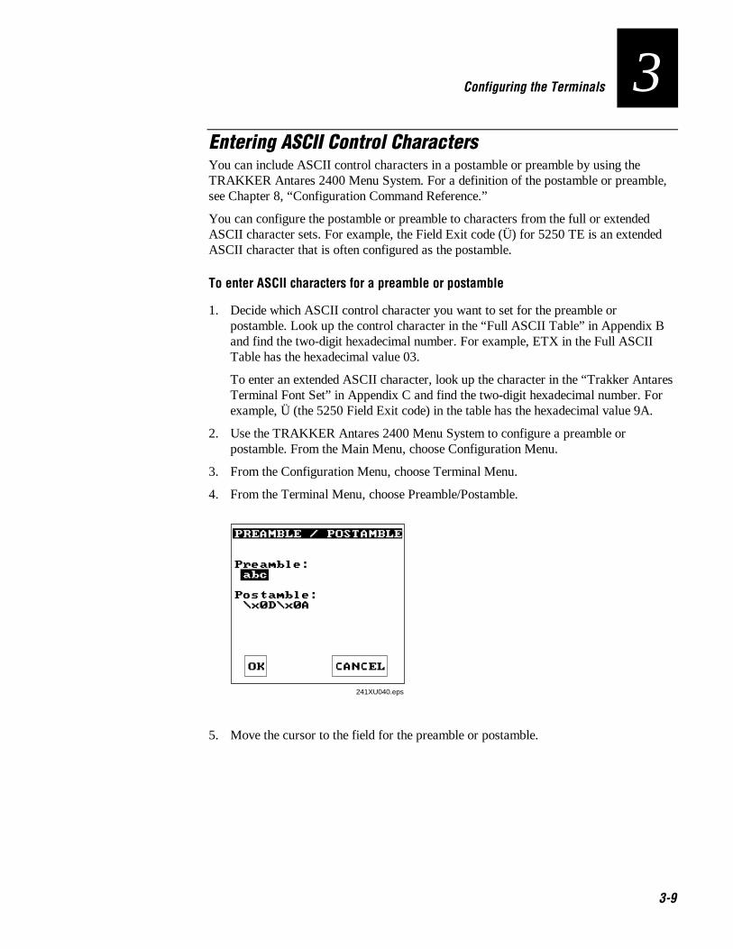
Co de 39 Nugget Configuring the Terminals
3-9
3Entering ASCII Control CharactersYou can include ASCII control characters in a postamble or preamble by using theTRAKKER Antares 2400 Menu System. For a definition of the postamble or preamble,see Chapter 8, “Configuration Command Reference.”
You can configure the postamble or preamble to characters from the full or extendedASCII character sets. For example, the Field Exit code (Ü) for 5250 TE is an extendedASCII character that is often configured as the postamble.
To enter ASCII characters for a preamble or postamble
1. Decide which ASCII control character you want to set for the preamble orpostamble. Look up the control character in the “Full ASCII Table” in Appendix Band find the two-digit hexadecimal number. For example, ETX in the Full ASCIITable has the hexadecimal value 03.
To enter an extended ASCII character, look up the character in the “Trakker AntaresTerminal Font Set” in Appendix C and find the two-digit hexadecimal number. Forexample, Ü (the 5250 Field Exit code) in the table has the hexadecimal value 9A.
2. Use the TRAKKER Antares 2400 Menu System to configure a preamble orpostamble. From the Main Menu, choose Configuration Menu.
3. From the Configuration Menu, choose Terminal Menu.
4. From the Terminal Menu, choose Preamble/Postamble.
PREAMBLE / POSTAMBLE Preamble: abc Postamble: \x0D\x0A
241XU040.eps
OK CANCEL
5. Move the cursor to the field for the preamble or postamble.
Trakker Antares 241X Hand-Held Terminal User’s Manual Co de 39 Nugget
3-10
6. Type the control character, extended ASCII character, or escape character sequencein the preamble or postamble field.
• To type a control character or extended ASCII character in the preamble orpostamble field, use this syntax:
\x hh
where hh is the two-digit hexadecimal number for the control character or theextended ASCII character.
• To type an escape character (backslash) in the preamble or postamble field, youmust type two backslashes. The application ignores the first backslash (\)character and saves the next character(s). For example:
Enter TheseCharacters Preamble/Postamble Saved
\\ \
\\k \k
\ no data
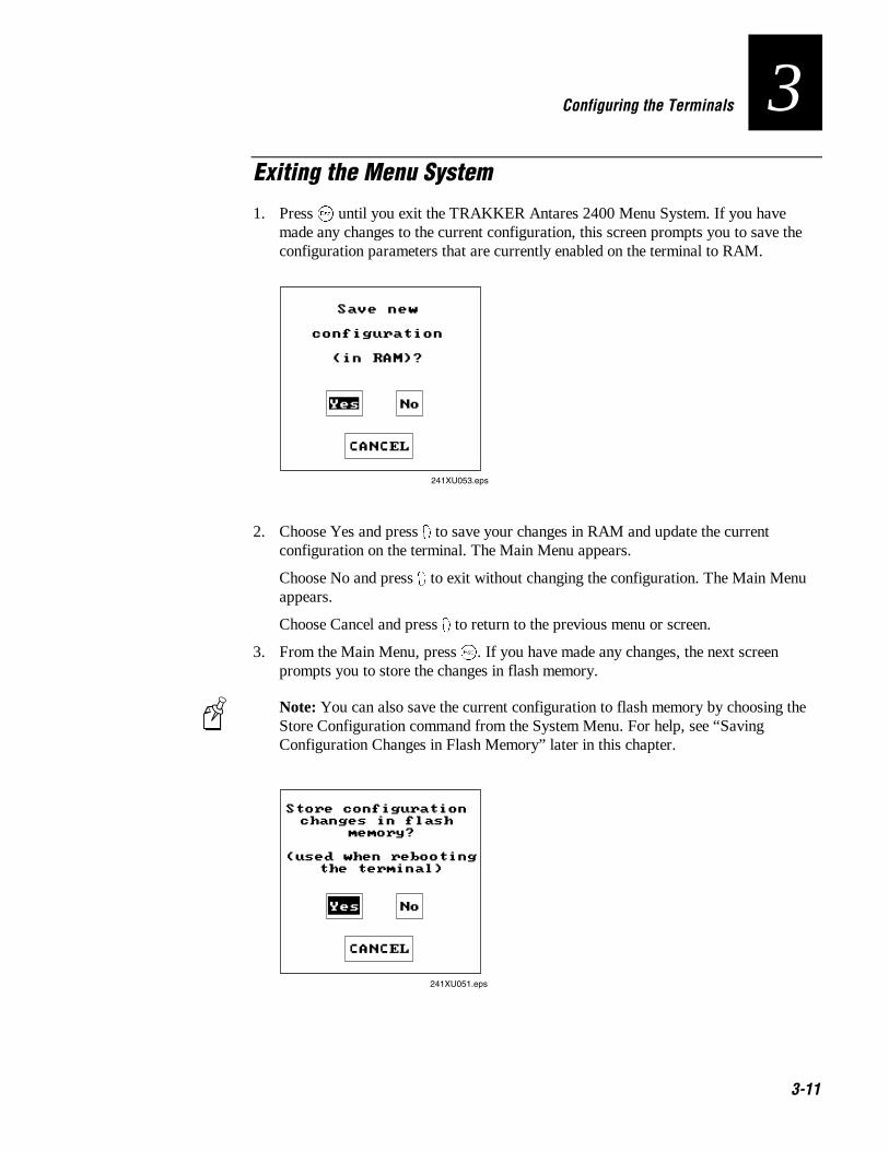
Co de 39 Nugget Configuring the Terminals
3-11
3Exiting the Menu System
1. Press � until you exit the TRAKKER Antares 2400 Menu System. If you havemade any changes to the current configuration, this screen prompts you to save theconfiguration parameters that are currently enabled on the terminal to RAM.
Save new
configuration
(in RAM)?
241XU053.eps
Yes No
CANCEL
2. Choose Yes and press 8 to save your changes in RAM and update the currentconfiguration on the terminal. The Main Menu appears.
Choose No and press 8 to exit without changing the configuration. The Main Menuappears.
Choose Cancel and press 8 to return to the previous menu or screen.
3. From the Main Menu, press �. If you have made any changes, the next screenprompts you to store the changes in flash memory.
Note: You can also save the current configuration to flash memory by choosing theStore Configuration command from the System Menu. For help, see “SavingConfiguration Changes in Flash Memory” later in this chapter.
Store configuration changes in flash
memory?
(used when rebooting the terminal)
241XU051.eps
Yes No
CANCEL
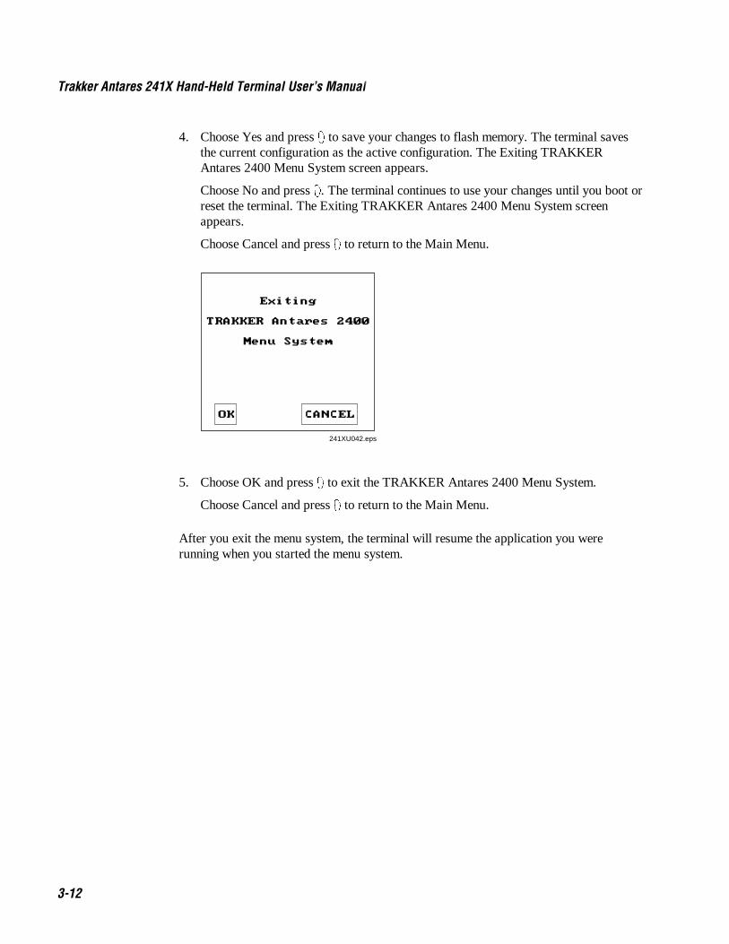
Trakker Antares 241X Hand-Held Terminal User’s Manual Co de 39 Nugget
3-12
4. Choose Yes and press 8 to save your changes to flash memory. The terminal savesthe current configuration as the active configuration. The Exiting TRAKKERAntares 2400 Menu System screen appears.
Choose No and press 8. The terminal continues to use your changes until you boot orreset the terminal. The Exiting TRAKKER Antares 2400 Menu System screenappears.
Choose Cancel and press 8 to return to the Main Menu.
Exiting
TRAKKER Antares 2400
Menu System
241XU042.eps
OK CANCEL
5. Choose OK and press 8 to exit the TRAKKER Antares 2400 Menu System.
Choose Cancel and press 8 to return to the Main Menu.
After you exit the menu system, the terminal will resume the application you wererunning when you started the menu system.

Co de 39 Nugget Configuring the Terminals
3-13
3Configuring the Terminal by Scanning Bar Code Labels
You can configure the terminal by scanning bar code labels that are listed in this manualor by creating your own Code 39 or Code 93 bar code labels. For example, you can scanthis bar code label to set the beep volume to a quiet audio level:
Set Beep Volume to Quiet
*$+BV1**$+BV1*
If you are using a different symbology to encode your bar code labels, you must enablethe symbology on your terminal. To ensure that the terminal can operate quickly andefficiently, you should enable only the bar code symbologies that you are going to scan.When you enable each bar code symbology, you may need to set a check digit, the lengthof the bar code label, or other options. For help, see the bar code symbology in Chapter8, “Configuration Command Reference.”
As you scan bar code labels that configure the terminal, the terminal accepts and sets allcommands. However, the terminal only uses the parameters that are valid for the currentconfiguration. For example, if you are configuring COM1 to use the Configurableprotocol and you disable Handshake and you set a value for Poll, the terminal will set thevalue for Poll, but it will not use this value since Handshake is disabled.
If you want your changes to exist after you boot or reset the terminal, you must save yourchanges in the terminal’s flash memory. For help, see “Saving Configuration Changes inFlash Memory” later in this chapter.
Note: If you are working in the TRAKKER Antares 2400 Menu System, you cannotscan configuration commands. Exit the menu system to scan configuration commands.
To configure the terminal, you can scan four separate bar code labels or you can createbar code labels that contain more than one configuration command. For example, you cancreate one bar code label to configure the terminal for:
• One-Shot Scanner mode (SB0)
• Scanner Redundancy set to high (SR2)
• Beep Volume set to very loud (BV4)
• Disable Keypad Clicker (KC0)
One-Shot Scanner Mode, Set Scanner Redundancy to High, Set Beep Volume to Very Loud,Disable Keypad Clicker
*$+SB0SR2BV4KC0**$+SB0SR2BV4KC0*

Trakker Antares 241X Hand-Held Terminal User’s Manual Co de 39 Nugget
3-14
When you create a bar code label to set several configuration commands, follow theserules:
• The bar code label must be printed using Code 39 or Code 93 symbology. If youneed to scan a Code 39 bar code label that includes quotes or periods, you mustconfigure the terminal to use Code 39 in Full ASCII mode.
• The bar code label must include the start and stop character. Most bar code printingutilities automatically include the start and stop character.
• The bar code label must start with $+ (Change Configuration command).
• Each configuration command must include the command syntax and the value for thecommand. For example, BV is the command syntax for Beep Volume and the value 4sets the beep volume to very loud.
• If you set one configuration command to a string of ASCII characters and anotherconfiguration command follows, you must enclose the value in quotes. If you do notinclude the quotation marks, the terminal may interpret everything after the firstcommand as data and will not find the second configuration command.
For example, to set the preamble to BV, use $+ADBV (no quotes are needed). To setthe preamble to BV and turn off the beep volume, use $+AD"BV"BV0, or change theorder and use $+BV0ADBV. To clear the preamble and postamble from a singlelabel, use $+AD""AE.
• To include quotation marks when you set a value, the entire value must be enclosedin quotation marks. Type two sets of quotation marks ("") to include one quotationmark as the value for a command. For example, to set the preamble to ABC"D, use$+AD"ABC""D".

Co de 39 Nugget Configuring the Terminals
3-15
3Configuring the Terminal Through the Serial Port
You can write a host application that configures the terminal by sending reader andconfiguration commands through the serial port. You must connect the terminal to thehost by either using a special cable or a communications dock and a special cable. Theterminal and the host must be communicating. On the terminal you must enable Framemode and the Configuration Commands Via Serial Port command.
For a list of reader commands, see Chapter 7, “Reader Command Reference.” For a listof configuration commands, see Chapter 8, “Configuration Command Reference.”
Note: You can continue running an application on the terminal while configuring theterminal from the host.
To set up the application
• Write a host application that can send transactions to and receive transactions fromthe terminal in this format:
SOM TMF field reader/configuration commands EOM
where:
SOM is the start of message field.
TMF field is only used if the Configuration Commands Via Serial Port areenabled with TMF. It is a 2-byte field containing one of these values:
CG Configuration Get request sent from the host application.
Cg Configuration Get response sent from the terminal to the host.
CS Configuration Set request sent from the host application.
Cs Configuration Set response sent from the terminal to the host.
Note: If the Configuration Commands Via Serial Port are enabled without TMF,leave this field blank.
commands are the reader and configuration commands that you want to set on theterminal or get the current value of from the terminal.
EOM is the end of message field.
Note: To send data to an application instead of sending configuration commands, use theletter A followed by a space in the TMF field. If the TMF field does not contain CG, Cg,CS, Cs, or A, the terminal ignores the transaction.

Trakker Antares 241X Hand-Held Terminal User’s Manual Co de 39 Nugget
3-16
Example with TMFIn the host application, you want to set the values for the beep volume and the displaybacklight timeout on the terminal. Send this transaction from the host application:
CS$+BV4DF30.+1
Note: SOM and EOM are not shown in this example.
where:
CS is a TMF Configuration Set request.
$+ is the Change Configuration reader command.
BV4 sets the Beep Volume command to a value of 4, which is a very loud beepvolume.
DF30 sets the Display Backlight Timeout command to a value of 30 seconds.
.+1 saves the configuration changes to the terminal’s flash memory.
The terminal returns this transaction to the host application.
Cs$+BV4DF30.+1
where:
Cs is a TMF Configuration Set response.
$+ is the Change Configuration reader command.
BV4 means the Beep Volume command has been changed to a value of 4, which is avery loud beep volume.
DF30 means the Display Backlight Timeout command has been changed to a value of30 seconds.
.+1 means the configuration changes have been saved in flash memory.

Co de 39 Nugget Configuring the Terminals
3-17
3Configuring the 2415 Through the Network
You can configure the 2415 by using one of these methods:
• Send a command from the DCS 300 (UDP Plus network only).
• Send a command from an application on the host computer (UDP Plus and TCP/IPnetworks).
The terminal must be communicating with the RF network. You must have alreadyinstalled and configured the access points. If you are using a UDP Plus network, youmust have installed and configured the DCS 300. You cannot configure any of the RFnetwork parameters, such as terminal IP address, over the network; you must havealready configured these parameters on each terminal.
For a list of reader commands, see Chapter 8, “Reader Command Reference.” For a listof configuration commands, see Chapter 9, “Configuration Command Reference.”
Note: You can continue running an application on the terminal while configuring theterminal from the network.
Sending a Command From the DCS 300If your 2415s are communicating using UDP Plus, you can use the DCS 300 to sendreader and configuration commands to one or more of these terminals. The DCS 300 letsyou group terminals together that you want to receive the same commands. For example,you may want to set the Beep Volume to very loud and turn on Keypad Caps Lock for allthe terminals in one area.
Note: You can configure a 2415 from the DCS 300, but you cannot get configurationdata from the terminal.
To send commands from the DCS 300
1. Using the Download Server feature on the server, select the terminal or group towhich you want to download the reader and configuration commands and then chooseEdit. For help on configuring a group of terminals, see the DCS 300 System Manual.

Trakker Antares 241X Hand-Held Terminal User’s Manual Co de 39 Nugget
3-18
2. In the Initialization Data box, choose the Command option button.
3. In the Initialization Data box field, enter the reader or configuration command andthen choose Add. The command appears in the Files and Data box.
For example, enter this command to set the Beep Volume to very loud:
$+BV4
Note: You can set the Postamble or Preamble configuration command to usecharacters from the extended ASCII character set such as the Field Exit code for5250 TE.
4. Repeat Step 3 to add another reader or configuration command, or choose OK.
5. To save the configuration changes in flash memory, enter .+1 as the last command.
If you do not save the configuration changes in flash memory, the commands onlychange the current configuration.
6. Choose OK to go to the Terminal Download Configuration dialog box.
7. Choose Download to download the commands and change the configuration of theterminals selected.

Co de 39 Nugget Configuring the Terminals
3-19
3Sending a Command From the HostYou can write a host application that configures the terminal. This host application mustbe able to communicate with the DCS 300 in a UDP Plus network or be able tocommunicate directly through the access point in a TCP/IP direct connect network.
Configuring the 2415 in a UDP Plus NetworkYou can use the host computer to configure a 2415 in your UDP Plus network. To sendand receive configuration data or files, you need to write a host application that cancommunicate with the DCS 300. For help, see the DCS 300 Technical ReferenceManual. You use the Terminal Message Format (TMF) protocol in the RF network tosend and receive transactions between the host application and the terminal.
To set up the DCS 300
• Configure a peer-to-peer destination name for the host application. Create atransaction ID, $NGCFGRSP, that will be routed to this destination name. TheDCS 300 uses the transaction ID to route responses from the 2415 back to the hostapplication. $NGCFGRSP is a special transaction ID that the server uses to forwardconfiguration response data from a terminal.
All configuration responses will be routed with the $NGCFGRSP transaction ID.The DCS 300 cannot keep track of multiple applications sending reader orconfiguration commands. If you have two host applications sending reader orconfiguration commands, they must both be configured to receive the $NGCFGRSPtransactions, and therefore both will receive all responses from all 2415s.
To set up the host computer
• Verify that the host computer can communicate with the DCS 300.
To set up the application
• Prepare and write a host application that can communicate with the DCS 300 andsend transactions to and receive transactions from the 2415 in this format:
transaction header TMF field reader/configuration commands
where:
transaction is a 96-byte field containing the message number, date and time, sourceheader application ID, destinations application ID, transaction ID, and other
information. You must set the system message (SYS$MSG) flag to Ein the transaction header. For help, see the DCS 300 TechnicalReference Manual.
Trakker Antares 241X Hand-Held Terminal User’s Manual Co de 39 Nugget
3-20
TMF field is a 2-byte field containing one of these values:
CG Configuration Get request sent from the host application.
Cg Configuration Get response sent from the 2415 to the host.
CS Configuration Set request sent from the host application.
Cs Configuration Set response sent from the 2415 to the host.
commands are the reader and configuration commands that you want to set on theterminal, or the current value you want to retrieve from the terminal.To save configuration changes in flash memory, send the readercommand .+1 as the last command.
For a list of commands, see Chapter 7, “Reader Command Reference,”or Chapter 8, “Configuration Command Reference.”
To see examples of the host application transactions, see “Example 1” and “Example 2”later in this chapter.
Configuring the 2415 in a TCP/IP Direct Connect NetworkYou can use the host computer to configure a 2415 in your TCP/IP network. To send andreceive configuration data, you need to write a host application that can communicatewith a 2415 directly via an access point. You use the Terminal Message Format (TMF)protocol in the RF network to send and receive transactions between the host applicationand the terminal. For more about developing an application, see “Transferring Files in aTCP/IP Direct Connect Network” later in this chapter.
Note: You can continue running an application on the 2415 while configuring theterminal from the host.
To set up the host computer
• Verify that you can communicate with the 2415.
To set up the application
• Prepare and write a host application that can communicate with the 2415.Configuration commands must be sent to network port 6000 on the terminal.Message transactions to and receive transactions from the 2415 on network port6000 must conform to the following format:
TMF field reader/configuration commands

Co de 39 Nugget Configuring the Terminals
3-21
3where:
TMF field is a 2-byte field containing one of these values:
CG Configuration Get request sent from the host application.
Cg Configuration Get response sent from the 2415 to the host.
CS Configuration Set request sent from the host application.
Cs Configuration Set response sent from the 2415 to the host.
commands are the reader and configuration commands that you want to set on theterminal, or the current value you want to retrieve from the terminal.To save configuration changes in flash memory, send the readercommand .+1 as the last command.
For a list of commands, see Chapter 7, “Reader Command Reference,”or Chapter 8, “Configuration Command Reference.”
Example 1In the host application, you want to get the current values of two configurationcommands from the 2415. Send this transaction from the host application:
CG$+NADF
Note: The transaction header is not shown in this example. You do not need a transactionheader for a host application in a TCP/IP network.
where:
CG is a TMF Configuration Get request.
$+ is the Change Configuration reader command.
NA is the Network Activate configuration command.
DF is the Display Backlight Timeout configuration command.
The 2415 returns this transaction to the host application.
Cg$+NA1DF60
where:
Cg is a TMF Configuration Get response.
$+ is the Change Configuration reader command.
NA1 means the Network Activate configuration command is currently set to a valueof 1, which means that the 2.4 GHz RF network is enabled.
DF60 means the Display Backlight Timeout configuration command is currently setto a value of 60 seconds.

Trakker Antares 241X Hand-Held Terminal User’s Manual Co de 39 Nugget
3-22
Example 2In the host application, you want to set the value for two configuration commands on the2415. Send this transaction from the host application:
CS$+BV4DF30
Note: The transaction header is not shown in this example. You do not need a transactionheader for a host application in a TCP/IP network.
where:
CS is a TMF Configuration Set request.
$+ is the Change Configuration reader command.
BV4 sets the Beep Volume configuration command to a value of 4, which is a veryloud beep volume.
DF30 sets the Display Backlight Timeout configuration command to a value of 30seconds.
The 2415 returns this transaction to the host application.
Cs$+BV4DF30
where:
Cs is a TMF Configuration Set response.
$+ is the Change Configuration reader command.
BV4 means the Beep Volume configuration command has been changed to a value of4, which is a very loud beep volume.
DF30 means the Display Backlight Timeout configuration command has beenchanged to a value of 30 seconds.
Co de 39 Nugget Configuring the Terminals
3-23
3Transferring Files in a TCP/IP Direct Connect Network
In a TCP/IP direct connect network, you can use a host application to transfer files andto send data between the terminal and a host.
To initiate file transfers from the host, you must write a host application that cancommunicate directly with a 2415. You use the file management reader commands, suchas Receive File and Transmit File, to transfer files between the 2415 and the host. Forhelp, see Chapter 7, “Reader Command Reference.”
To initiate file transfers from the terminal, you do not need to develop a host applicationas described in this section. You can use the file management reader commands ReceiveFile and Transmit File within a terminal application or by scanning bar code labels. Forhelp, see Chapter 7, “Reader Command Reference.”
To use the built-in TFTP client on the 2415, the:
• TFTP (Trivial File Transfer Protocol) server must be running on the host.
• TFTP server must be running on at least a Pentium processor or equivalent.
• 2415 must be communicating with the host that is running the TFTP server.
• TFTP server or some other application on the host must be able to send the readercommand on the network.
Note: You can continue running any application, except TE, on the 2415 whiletransferring files from the host.
To transfer files or send configuration data from the host
1. Make sure the TFTP server is running on the host and the 2415 is communicatingwith the host.
2. Start the host application that can send reader commands to the terminal.
3. Send the two-character TMF code, CS (Configuration Set request) followed by thereader or configuration command. For help, see “Configuring the 2415 in a TCP/IPDirect Connect Network” earlier in this chapter.
For example, to send the application INVENTRY.BIN from drive C on the host todrive C on the 2415, enter this command:
CS.%R,c:inventry.bin,c:inventry.bin

Trakker Antares 241X Hand-Held Terminal User’s Manual Co de 39 Nugget
3-24
CLIENT.CPP is the source for a sample application you can run on the host. You can useCLIENT.CPP to send reader commands to the 2415 and receive the resulting messages.
The source code for the sample utilities CLIENT.CPP and the include file UTILS.H isshown on the next pages. You can build the application using Microsoft Visual C++version 4.0 (or higher) and the Windows sockets library that is included with MicrosoftVisual C++. You can also develop your own application to meet the needs of your hostenvironment.
You run the resulting application (CLIENT.EXE) from the DOS command line. Theapplication expects NCM to be defined as the terminal IP address in the hosts file. Oncerunning, the application prompts you to enter a reader command, which it then sends tothe 2415. The application also displays any return messages. Reader commands arehandled by the Trakker Antares operating system, so you can continue running anapplication while you use the CLIENT.EXE application to send commands.

Co de 39 Nugget Configuring the Terminals
3-25
3CLIENT.CPP Sample Application for a TCP/IP Direct Connect Network
#include <windows.h>#include <stdio.h>#include "d:\class\Utils.h"
// our application uses a fixed port numberconst unsigned short SERVER_PORT = 6000;const unsigned short CLIENT_PORT = 6001;// we will default to the local host machine// unless argv[1] has a hostnameconst char SERVER_HOSTNAME[] = "ncm";
int main(int argc, char *argv[]){// turn on the socket library for this process WSADATA wsad; int error = WSAStartup(MAKEWORD(1,1), &wsad); if (error != 0) ErrorMessage("WSAStartup", WSAGetLastError());
// create an unitialized connection-oriented socket SOCKET connection; connection = socket(PF_INET, SOCK_DGRAM, 0); if (connection == INVALID_SOCKET) ErrorMessage("socket", WSAGetLastError());
// lookup the IP address of the requested host HOSTENT *phostent = gethostbyname(argc == 2 ? argv[1] : SERVER_HOSTNAME); if (phostent == 0) ErrorMessage("gethostbyname", WSAGetLastError());
// define a SOCKADDR to contain the IP address of the// server and the port number of our application SOCKADDR_IN serverAddress; memset(&serverAddress, 0, sizeof(serverAddress)); serverAddress.sin_family = PF_INET; serverAddress.sin_port = htons(SERVER_PORT); memcpy(&serverAddress.sin_addr, phostent->h_addr_list[0], phostent->h_length);// Bind a well known port of 6000 to the socket
SOCKADDR_IN clientAddress;memset(&clientAddress, 0, sizeof(clientAddress));clientAddress.sin_family = PF_INET;clientAddress.sin_port = htons(CLIENT_PORT);clientAddress.sin_addr.s_addr = htonl(INADDR_ANY);if(!(bind(connection, (LPSOCKADDR)&clientAddress, sizeof(clientAddress))==0)){
ErrorMessage("bind", WSAGetLastError());}

Trakker Antares 241X Hand-Held Terminal User’s Manual Co de 39 Nugget
3-26
CLIENT.CPP Sample Application for a TCP/IP Direct Connect Network (continued)
// attempt to connect to the server error = connect(connection, (const SOCKADDR *)&serverAddress, sizeof(serverAddress)); if (error != 0) ErrorMessage("connect", WSAGetLastError());
// check the local name for the socketSOCKADDR_IN localName;memset(&localName, 0, sizeof(localName));int localNameLength = sizeof(localName);error = getsockname(connection, (LPSOCKADDR)&localName, &localNameLength);
// run the user-interface char sz[1024];
char rz[1024]; BOOL bConnectionAlive = TRUE; printf("> ");
int Scount, Rcount; int cbRecv, cbSend; Scount = Rcount = 0; int cbLen, rcLen; unsigned char *psend = (unsigned char *)sz;
// continue while not EOF on the console and the connection is alive while (bConnectionAlive) {// send the string entered by the user
printf("Enter Command:\n"); printf("> "); gets(sz); if(sz[0] != 'q') {
cbLen = strlen(sz);cbSend = send(connection, (const char *)psend, cbLen, 0);if (cbSend < 0){
Scount++;printf("send failed %d\n", Scount);bConnectionAlive = FALSE;ErrorMessage("send", WSAGetLastError());
} Sleep(2000);
// receive the converted string from the servermemset(&rz, 0, sizeof(rz));rcLen = sizeof(rz);cbRecv = recv(connection, rz, rcLen, 0);if (cbRecv < 0){
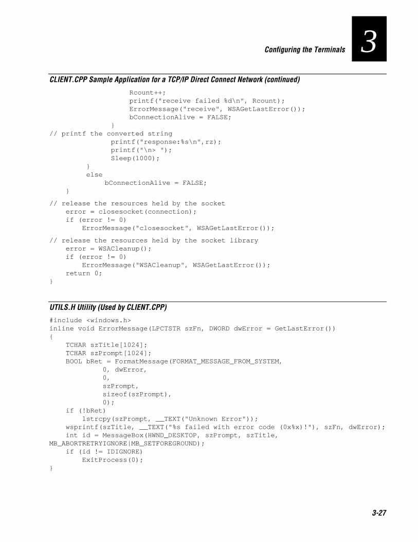
Co de 39 Nugget Configuring the Terminals
3-27
3CLIENT.CPP Sample Application for a TCP/IP Direct Connect Network (continued)
Rcount++;printf("receive failed %d\n", Rcount);ErrorMessage("receive", WSAGetLastError());bConnectionAlive = FALSE;
}// printf the converted string
printf("response:%s\n",rz);printf("\n> ");Sleep(1000);
} else
bConnectionAlive = FALSE; }
// release the resources held by the socket error = closesocket(connection); if (error != 0) ErrorMessage("closesocket", WSAGetLastError());
// release the resources held by the socket library error = WSACleanup(); if (error != 0) ErrorMessage("WSACleanup", WSAGetLastError()); return 0;}
UTILS.H Utility (Used by CLIENT.CPP)
#include <windows.h>inline void ErrorMessage(LPCTSTR szFn, DWORD dwError = GetLastError()){ TCHAR szTitle[1024]; TCHAR szPrompt[1024]; BOOL bRet = FormatMessage(FORMAT_MESSAGE_FROM_SYSTEM, 0, dwError, 0, szPrompt, sizeof(szPrompt), 0); if (!bRet) lstrcpy(szPrompt, __TEXT("Unknown Error")); wsprintf(szTitle, __TEXT("%s failed with error code (0x%x)!"), szFn, dwError); int id = MessageBox(HWND_DESKTOP, szPrompt, szTitle,MB_ABORTRETRYIGNORE|MB_SETFOREGROUND); if (id != IDIGNORE) ExitProcess(0);}

Trakker Antares 241X Hand-Held Terminal User’s Manual Co de 39 Nugget
3-28
Saving Configuration Changes to Flash MemoryIf you configure the terminal by scanning bar code labels, through the serial port, or fromthe network, you may want to save the changes in flash memory using one of thesemethods.
To save configuration changes using the menu system
1. Press � 8 0 � ) or press � 8 � � � or scan this bar code label:
Enter Test and Service Mode
*..-.**..-.*
The Main Menu appears.
2. Choose System Menu and press 8. The System Menu appears.
SYSTEM MENU File Manager Load Default Values Set Time and Date Store Configuration Upgrade Firmware ⁄ _` Select item [Enter] Next screen [F1] Help [Esc] Exit
241XU044.eps
3. Choose the Store Configuration command and press 8. The Store Configurationscreen appears.
STORE CONFIGURATION Store Configuration in Flash Memory
241XU045.eps
CANCELOK
Co de 39 Nugget Configuring the Terminals
3-29
34. Choose OK to save the configuration in flash memory. To exit without saving the
configuration, choose Cancel. The System Menu appears.
5. Press � to exit the System Menu. The Main Menu appears.
6. Choose another menu from the Main Menu or press � to exit the TRAKKERAntares 2400 Menu System.
To save configuration changes by scanning a bar code label
• Scan this bar code label:
Save Configuration in Flash Memory
*.+1**.+1*
To save configuration changes by sending a command through the network
• Send .+1 as the last command from the host application or the DCS 300.
Restoring the Terminal’s Default ConfigurationThe default configuration for the terminal is listed in Appendix A. You can restore theterminal’s default configuration by using the TRAKKER Antares 2400 Menu System, byscanning the Default Configuration bar code label, or by sending a command from thenetwork.
Note: If you restore the default configuration, you must set the primary networkcommunications parameters on the 2415 to reestablish communications with otherdevices in the RF network. You may also need to reset the serial port parameters tocommunicate with another device through the serial port.
To restore the default configuration using the menu system
1. Press � 8 0 � ) or press � 8 � � � or scan this bar code label:
Enter Test and Service Mode
*..-.**..-.*
The Main Menu appears.
2. Choose System Menu and press 8. The System Menu appears.

Trakker Antares 241X Hand-Held Terminal User’s Manual Co de 39 Nugget
3-30
3. Choose the Load Default Values command and press 8. The Load Default Valuesscreen appears.
LOAD DEFAULT VALUES
Load default configuration values in RAM?
(Overwrites current
configuration)
241XU048.eps
OK CANCEL
4. Choose OK and press 8 to load the default configuration values. The default valueswill override the current runtime configuration on the terminal.
To exit without loading the default values, choose Cancel and press 8. The SystemMenu appears.
5. Press � to exit the System Menu. The Main Menu appears.
6. Choose another menu from the Main Menu or press � to exit the TRAKKERAntares 2400 Menu System. For help exiting the menu system, see “Exiting theTRAKKER Antares 2400 Menu System” earlier in this chapter.
To restore the default configuration by scanning a bar code label
• Scan this bar code label:
Default Configuration
*.+0**.+0*
To restore the default configuration by sending a command through the network
• Send .+0 from the host application or the DCS 300.

Nugg Co de 39
Using Custom Applications
4

Nugg Co de 39
4-2

Nugg Co de 39 Using Custom Applications
4-3
4This chapter explains how to create, download, and run custom applications on theprogrammable terminals.
How To Download and Run ApplicationsHere’s a brief summary of the steps you follow to download applications and files to theprogrammable terminals. To learn more about the programmable features, start with thenext section, “About the Trakker Antares Programmable Terminals.”
Use the serial port to download applications and files to the terminal
1. Create your applications using the Trakker Antares Programmer’s Software Kit(PSK) or EZBuilder. For help, see page 4-6.
2. Convert each application to a binary file using the PSK utility EXE2ABS.EXE. Forhelp, see page 4-8. Or, use FileCopy or EZBuilder to convert each application to abinary file.
3. Connect the terminal’s serial port to the host computer or PC. For help, see “Usingthe Terminal’s Serial Port” in Chapter 1.
Or, insert the terminal into a communications dock and connect the dock to the hostcomputer or PC. For help, see the Trakker Antares TD2410 Communications DockQuick Reference Guide.
4. Use the FileCopy utility or LOADER.EXE on the host computer or PC to downloadapplications and files to the terminal. For help, see page 4-9.
5. Use the TRAKKER Antares 2400 Menu System to load and run an application. Forhelp, see page 4-19.
Use the DCS 300 to download applications and files to the 2415
1. Create your applications using the Trakker Antares PSK or EZBuilder. For help, seepage 4-6.
2. Convert each application to a binary file using the PSK utility EXE2ABS.EXE. Forhelp, see page 4-8. Or, use FileCopy or EZBuilder to convert each application to abinary file.
3. Copy the applications and files to the DCS 300. For help, see page 4-14.
4. Use the Download Server feature on the DCS 300 to download applications and filesto the 2415. For help, see page 4-16.
5. Use the TRAKKER Antares 2400 Menu System to load and run an application. Forhelp, see page 4-19.

Trakker Antares 241X Hand-Held Terminal User’s Manual Nugg Co de 39
4-4
Use a host application to download applications and files to the 2415
1. Create your applications using the Trakker Antares PSK or EZBuilder. For help, seepage 4-6.
2. Convert each application to a binary file using the PSK utility EXE2ABS.EXE. Forhelp, see page 4-8. Or, use FileCopy or EZBuilder to convert each application to abinary file.
3. Copy the applications and files to the host.
4. Write a host application that can communicate with the 2415 directly via an accesspoint. Use the host application to download applications and files to the 2415. Forhelp, see “Transferring Files in a TCP/IP Direct Connect Network” in Chapter 3.
5. Use the TRAKKER Antares 2400 Menu System to load and run an application. Forhelp, see page 4-19. Or, use the host application to send the Run Program command.
About the Trakker Antares Programmable Terminals
A sample application was installed on your programmable terminals at the factory. Usethis sample application to verify that your terminals are communicating with yournetwork. You can develop your own data collection application for the terminal and thendownload the application and any associated files to the terminal. Each terminalcompletes the download task differently:
2410 You connect the host computer or PC to the terminal’s serial port and thendownload applications and files.
2415 You download applications and files from the DCS 300 or host to one or moreterminals through the RF network. You can also download applications and files throughthe terminal’s serial port.
The next table lists specifications and technical information you need to know to developapplications for the terminals.

Nugg Co de 39 Using Custom Applications
4-5
4Trakker Antares Programmable Terminal Specifications
Products: 2410
2415
Serial communications: RS-232 serial communications via the terminal’s serial port or the terminal in acommunications dock.
RF communications: 2.4 GHz (to 2.4835 GHz )
RF network support: There are two options:
• host connectivity through an access point and DCS 300 using UDP Plus
• host connectivity through an access point using TCP/IP
Flash drive C: Approximately 750K for user, up to 128 files
Flash drive D or font set: Optional 2MB flash memory can be configured as an extended drive (up to 128 files)or used as storage for a double-byte font set
RAM drive E: 256K reserved for user application (configurable), up to 128 files
Extended drive G: (2410 option only) 2MB or 4MB extended drive, up to 128 files
Application: Programmed in Microsoft C, customer defined, stored on drive C. Maximum size of asingle application is 512K (less the size of the RAM drive, if configured).
Application name: Customer defined, eight characters with three-character extension
Storing applications: Multiple (maximum depends on the drive space)
Developing applications: Using Trakker Antares Programmer’s Software Kit (PSK) or EZBuilder
Downloading applications: Via RS-232 serial communications from the PC or host computer
Via RF to the 2415’s flash drive from the DCS 300
Via RF and TFTP to the 2415’s flash drive from a host application

Trakker Antares 241X Hand-Held Terminal User’s Manual Nugg Co de 39
4-6
Creating Applications for the TerminalYou create applications for the terminal using the Trakker Antares Programmer’sSoftware Kit (PSK) or EZBuilder and Microsoft C/C++ functions.The terminal runsapplications that are programmed in Microsoft C.
To start creating applications
1. Use the PSK or EZBuilder to develop your application.
2. Convert the application to a binary file.
Each step is described in the next sections. Once you have completed these steps, you candownload the application to the terminals.
Using the PSK or EZBuilder to Develop ApplicationsIntermec has two development tools, Trakker Antares PSK and EZBuilder, that you canuse to create applications for the terminals.
You can download the latest version of the PSK for free from the Intermec Web site atwww.intermec.com. This kit has a full set of programming tools to help you createapplications for the terminal, including:
• Programmer’s Software Kit (PSK)
• Application Simulator
• FileCopy utility
• Sample programs and Make files
The PSK is a library of C functions that control the programmable terminals. You canprogram the terminal to display prompts and error messages, to collect and display data,and to transmit data to an upline DCS 300 or host computer. The PSK functions workwith most standard Microsoft C functions. You can create complex applications thatcollect, store, manipulate, and transmit data to meet your system needs.
The Application Simulator is a terminate-and-stay resident (TSR) program that lets youdebug and run Trakker Antares applications on a DOS or Windows PC. The Simulatorcaptures the PSK and C functions and makes the PC mimic a terminal.
You can also download the Trakker Antares Application Development Tools SystemManual (Part No. 064433) in PDF format for free from the Intermec Web site. Or, youcan order a manual from your local Intermec representative.

Nugg Co de 39 Using Custom Applications
4-7
4EZBuilder (Part No. 066381) is a software code generator product that providesprogrammers and technically-oriented non-programmers with a quick and easy way tocreate applications for the terminal. EZBuilder v2.1 supports the 2410 and the 2415terminals. It contains:
• EZBuilder software
• Microsoft Visual C++ version 1.5X
• Application Simulator
• PSK libraries
• FileCopy utility
• Sample EZBuilder programs
• EZBuilder Getting Started Guide (Part No. 066450)
• EZBuilder Tutorial (Part No. 066449)
When you use EZBuilder, you enter simple commands to create menus, screens, andtransactions and to define menu items, labels, and data fields. You can also set attributes,define function keys, and specify other processing, such as calculations, for theapplication. Once you have defined the application, EZBuilder generates the applicationprogram code. The Application Simulator Editor mimics a terminal and lets you test theapplication on your computer.
Converting Applications Between JANUS and Trakker AntaresYou can develop applications that run on both the JANUS devices and the TrakkerAntares terminals. However, there are some differences that you need to plan for in yourapplications. The Trakker Antares terminal is an intelligent terminal. A JANUS device isa DOS-compatible computer. Because of these differences, there are some features andfunctions that are different between the JANUS PSK and the Trakker Antares PSK.
In general, a C/C++ application written for Trakker Antares terminals requires minorchanges to run on a JANUS device. However, an application written for a JANUS devicemay require more changes to work properly on a Trakker Antares terminal. JANUSapplications developed with the JANUS PSK and compiler libraries are relatively easy toconvert to an application for the Trakker Antares terminals.
There are several methods you can use to convert applications to and from JANUSdevices and Trakker Antares terminals. For help on converting applications, see theTrakker Antares PSK Reference Manual.
Converting IRL ProgramsThe terminals support IRL (Intermec Reader Language) by using IRL to C conversionprograms. You can convert IRL programs to Microsoft C/C++ applications that use theTrakker Antares PSK functions. For information about converting IRL programs,contact your local Intermec service representative.

Trakker Antares 241X Hand-Held Terminal User’s Manual Nugg Co de 39
4-8
Converting the Application to a Binary FileFor your application to run on the terminal, it must be stored as an executable binary file(*.BIN) instead of an executable file (*.EXE). You can use the EXE2ABS.EXE programthat comes with the Trakker Antares PSK or EZBuilder to convert the file.
Note: The EZBuilder “download” tool will automatically convert an executable file(*.EXE) to an executable binary file (*.BIN) when you download the file.
The FileCopy utility can automatically convert an executable file (*.EXE) to anexecutable binary file (*.BIN) if you check the Convert.EXE check box before youdownload the file.
To convert an executable file to a binary file
1. Use the Trakker Antares PSK or EZBuilder to develop the application.
2. Convert the application from an executable file to a binary file by typing thiscommand on your development PC:
drive :\intermec\imt24\lib\exe2abs filename .exe
The conversion application (EXE2ABS.EXE) creates an executable binary file namedfilename.BIN.
For example, if your application is named SHIPPING.EXE and the Intermec directoryis on drive C, type this command on your PC:
c:\intermec\imt24\lib\exe2abs shipping.exe
The conversion application creates the SHIPPING.BIN file.
3. If you have a 2415 and plan to download applications and files from the DCS 300 orhost, copy all the binary application files and any data files to a 3.5-inch disk.

Nugg Co de 39 Using Custom Applications
4-9
4Using the Serial Port to Transfer Applications and Files
You can download or upload applications and files between a host computer or PC andthe terminal through the terminal’s serial port. Once the terminal is connected, there arethree ways to transfer files:
• Use the FileCopy utility that ships with the Trakker Antares PSK and EZBuilder.
• Use the LOADER.EXE program that comes with the firmware upgrade kits.
• Use the Receive File or Transmit File reader commands. For help, see Chapter 7,“Reader Command Reference.”
This section explains how to use the FileCopy utility to download or upload applicationsand files to or from the terminal. FileCopy includes online help. Click the Help button orpress F1 anytime to get more information.
This section also explains how to use the LOADER.EXE program to downloadapplications to the terminal.
To run an application on the terminal, it must be stored as an executable binary file(.BIN). The FileCopy utility can automatically convert any .EXE file to a .BIN file if youcheck the Convert.EXE check box before you download the file. With the FileCopyutility, you can download either .EXE or .BIN application files. If you are usingLOADER.EXE to download an application, you need to use EXE2ABS.EXE to convertthe .EXE file to a .BIN file.
To transfer applications and files to or from the terminal using the FileCopy utility
1. Connect the terminal to your host computer or PC.
2. Start Microsoft Windows on your host computer or PC.
3. Run FileCopy. The TRAKKER Antares FileCopy Utility dialog box appears.
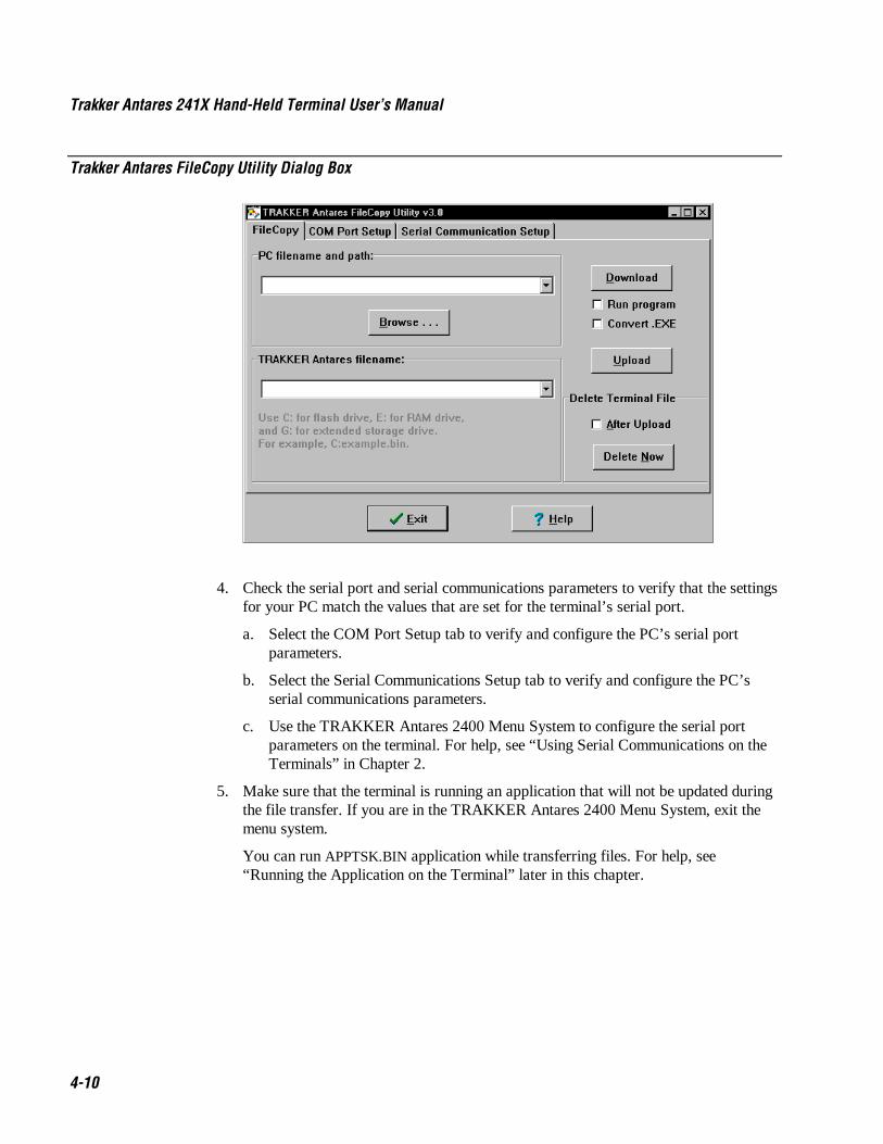
Trakker Antares 241X Hand-Held Terminal User’s Manual Nugg Co de 39
4-10
Trakker Antares FileCopy Utility Dialog Box
4. Check the serial port and serial communications parameters to verify that the settingsfor your PC match the values that are set for the terminal’s serial port.
a. Select the COM Port Setup tab to verify and configure the PC’s serial portparameters.
b. Select the Serial Communications Setup tab to verify and configure the PC’sserial communications parameters.
c. Use the TRAKKER Antares 2400 Menu System to configure the serial portparameters on the terminal. For help, see “Using Serial Communications on theTerminals” in Chapter 2.
5. Make sure that the terminal is running an application that will not be updated duringthe file transfer. If you are in the TRAKKER Antares 2400 Menu System, exit themenu system.
You can run APPTSK.BIN application while transferring files. For help, see“Running the Application on the Terminal” later in this chapter.

Nugg Co de 39 Using Custom Applications
4-11
46. Select the FileCopy tab to download or upload applications and files.
a. In the PC filename and path field, type the path and filename (filename.EXE orfilename.BIN) for the file on your PC. You can select a previously used filenamefrom a list by clicking on the down arrow.
To view the files on your PC, click the Browse button.
b. In the TRAKKER Antares filename field, type the drive and filename on theterminal. You can select a previously used filename from a list by clicking on thedown arrow.
You can only download applications to drive C. On the 2415, you can downloadfiles to drive C, D, or E. On the 2410, you can download files to drive C, D, E,or G (if available).
7. If you are downloading a *.BIN file and want to run it on the terminal immediatelyafter it is downloaded, check the Run program check box.
If you are downloading an *.EXE file and want to convert it to a *.BIN so you canrun it on the terminal immediately after it is downloaded, check the Run programcheck box and check the Convert.EXE check box.
8. Click Download to copy the file from the PC to the terminal. If you turned on theRun program check box, the terminal boots, resets, and runs the application youdownloaded. Otherwise, the current application continues to run on the terminal.
Or, click Upload to copy the file from the terminal to the PC.
9. To download or upload another file, repeat Step 5 through Step 7.
10. Click Exit to close the FileCopy utility.
You are ready to run the application from the terminal. For help, see “Running theApplication on the Terminal” later in this chapter.
To transfer applications and files to the terminal using LOADER.EXE
Note: Before you can transfer applications and files, open the MS-DOS window. Then,open the MS-DOS Prompt Properties dialog box. In the Memory tab, set the InitialEnvironment field to 4096. Close the MS-DOS window and re-open it.
1. Connect the terminal to your PC. For help connecting the terminal, see “Using SerialCommunications on the Terminals” in Chapter 2.
2. On your PC, load the application or file that you want to download.
3. Access the MS-DOS window.
4. Change to the directory that contains the LOADER.EXE program.

Trakker Antares 241X Hand-Held Terminal User’s Manual Nugg Co de 39
4-12
5. On the terminal, press � 8 0 � ) or press � 8 � � � or scan this bar codelabel:
Enter Test and Service Mode
*..-.**..-.*
The Main Menu appears.
6. Choose System Menu and press 8. The System Menu appears.
SYSTEM MENU File Manager Load Default Values Set Time and Date Store Configuration Upgrade Firmware ⁄ _` Select item [Enter] Next screen [F1] Help [Esc] Exit
241XU044.eps
7. Choose Upgrade Firmware and press 8. The Upgrade Firmware screen appears.
UPGRADE FIRMWARE Upgrade terminal
firmware? Make sure the terminal is connected to a host computer through the
optical adapter.
241XU060.eps
OK CANCEL
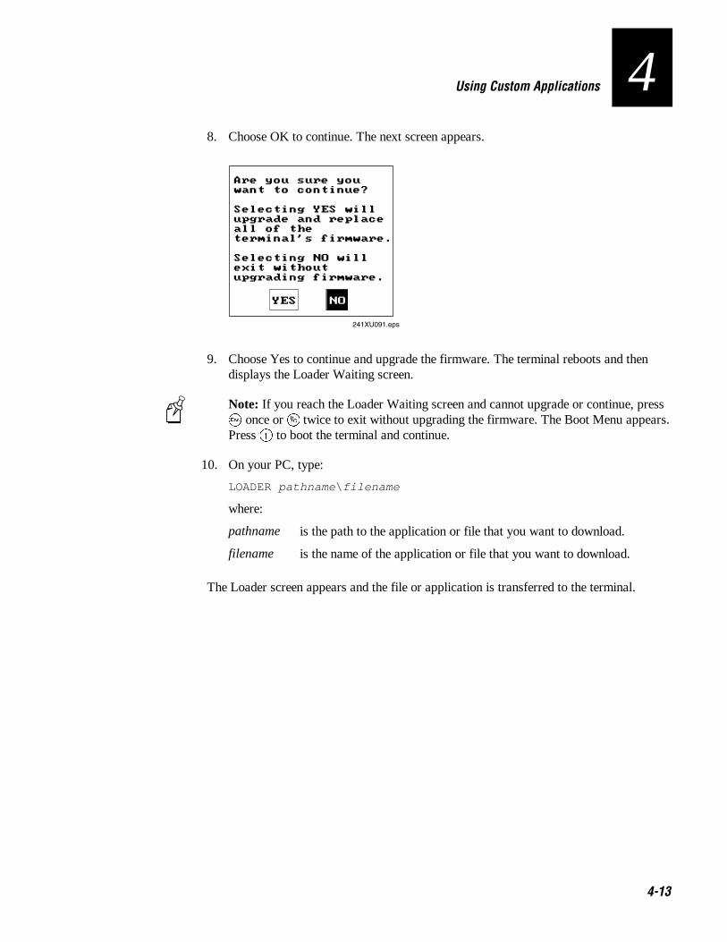
Nugg Co de 39 Using Custom Applications
4-13
48. Choose OK to continue. The next screen appears.
Are you sure you want to continue? Selecting YES will upgrade and replace all of the terminal's firmware. Selecting NO will exit without upgrading firmware.
241XU091.eps
YES NO
9. Choose Yes to continue and upgrade the firmware. The terminal reboots and thendisplays the Loader Waiting screen.
Note: If you reach the Loader Waiting screen and cannot upgrade or continue, press� once or : twice to exit without upgrading the firmware. The Boot Menu appears.Press � to boot the terminal and continue.
10. On your PC, type:
LOADER pathname \ filename
where:
pathname is the path to the application or file that you want to download.
filename is the name of the application or file that you want to download.
The Loader screen appears and the file or application is transferred to the terminal.

Trakker Antares 241X Hand-Held Terminal User’s Manual Nugg Co de 39
4-14
Using the DCS 300 to Download Applications and FilesYou can download applications and files to a 2415 using either the serial port or RFcommunications. For help downloading via the serial port, see the previous section. Theadvantage to downloading files via RF communications is that you can downloadmultiple files to one or more terminals.
You use RF communications to download applications and files from the DCS 300 to2415s in a UDP Plus network or from the host to 2415s in a TCP/IP network. Thissection explains how to use the DCS 300. Before you start, make sure the 2415 iscommunicating with the DCS 300. If you need any help installing or configuring thenetwork, see “Using RF Communications on the 2415s” in Chapter 2.
For help downloading applications and files in a TCP/IP network, see “Transferring Filesin a TCP/IP Direct Connect Network” in Chapter 3.
To download applications and files from the DCS 300
1. Copy the applications and files to the DCS 300. For help, see “Copying Applicationsand Files to the DCS 300” in the next section.
2. Use the Download Server feature on the DCS 300 to download the applications andfiles to the 2415. For help, see “Downloading Applications and Files to the 2415”later in this chapter.
Or, use the Receive File or Transmit File reader commands to download theapplications and files to the 2415. For help, see Chapter 7, “Reader CommandReference.”
Copying Applications and Files to the DCS 300
1. Copy the applications and files to a 3.5-inch disk.
2. Insert the disk into the disk drive of the DCS 300.
3. From the main menu sidebar buttons, choose File Handling. The File Handling dialogbox appears.
4. In the File Handling list box, select Restore User Files and choose OK. A messagebox appears telling you to insert the disk in the disk drive of the DCS 300.
5. Choose OK. The Restore User Files dialog box appears. The files on the floppy diskappear in the Available Files list box.

Nugg Co de 39 Using Custom Applications
4-15
4Restore User Files Dialog Box
6. In the Available Files list box, add all the files that you want to restore to theSelected Files list box.
a. Select the file name.
b. Choose Select. The file name appears in the Selected Files list box.
If the Selected Files list box shows any files that you do not want to restore, selectthe file name and choose Remove.
7. Choose Restore Files. The DCS 300 restores the files you selected to theD:\USERDATA directory.
8. Remove your disk from the disk drive.

Trakker Antares 241X Hand-Held Terminal User’s Manual Nugg Co de 39
4-16
Downloading Applications and Files to the 2415Once the applications and files are stored on the DCS 300, you can use the DownloadServer feature on the DCS 300 to download applications and files to one or more 2415s.
To prepare the terminal
1. Make sure the terminal is on and communicating with the DCS 300. The ConnectLED must be on.
2. Make sure the main battery pack is fully charged.
To download applications and files to the 2415
1. If data collection is not started on the DCS 300, choose Start Data Collection fromthe main menu sidebar buttons.
2. From the main menu sidebar buttons, choose System Maintenance. The SystemMaintenance dialog box appears.
3. In the System Maintenance dialog box, select Configure Download Server and thenchoose Start. The Terminal Download Configuration dialog box appears.
4. From the Terminal Download Configuration dialog box in the Terminals and Groupslist box, select a terminal or group of terminals to receive the binary applications andfiles.
For help defining a group of terminals, see the DCS 300 System Manual.

Nugg Co de 39 Using Custom Applications
4-17
45. Choose Edit. The Configure Device Initialization Download dialog box appears.
6. Verify that there are no files (or entries) listed in the Files and Data list box. If thereare entries, then choose Clear to remove them.
7. In the Initialization Data box, choose the File option button.
8. In the Initialization Data field, type:
\ filename
where filename is the name of the executable binary application. Or choose Find,select your application, and choose OK.
9. Check the Binary file check box.
10. Choose the Overwrite option button to overwrite an existing file with the same name.
11. In the Target file name field, type a name if you want to save the file under adifferent name on the terminal.
Do NOT enter a slash or backslash character before the target filename.

Trakker Antares 241X Hand-Held Terminal User’s Manual Nugg Co de 39
4-18
12. Choose Add. The file appears in the Files and Data list box with a B for binary in theleftmost column.
13. Repeat Steps 7 through 12 to select another application.
14. You can also download files used by your application such as an employee list or apart number list.
To download additional files, choose File in the Initialization Data box. Type in thefilename including the backslash. Disable the Binary file check box and then chooseAdd.
15. Choose OK to save your changes and return to the Terminal DownloadConfiguration dialog box.
16. In the Terminals and Groups list box, choose the terminal or group you configured ifit is not already highlighted and marked with an asterisk.
17. Choose Download. A Download initiated message box appears.
18. Choose OK. The executable binary applications and files are downloaded to theterminal or group of terminals. If you are downloading the applications and files tomany terminals or there is a lot of radio traffic in your RF network, the downloadmay take longer. All files are downloaded and stored on the terminal’s flash drive C.
To run an application, continue with the instructions in the next section. If you haveproblems downloading files, see Chapter 5, “Troubleshooting.”
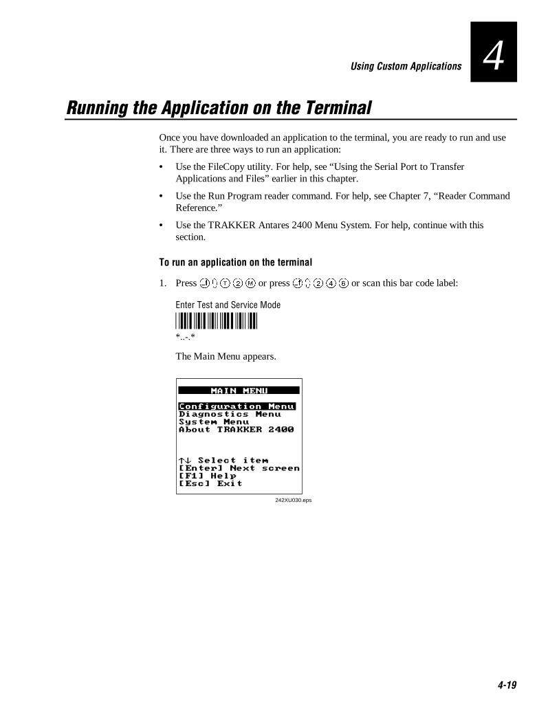
Nugg Co de 39 Using Custom Applications
4-19
4Running the Application on the Terminal
Once you have downloaded an application to the terminal, you are ready to run and useit. There are three ways to run an application:
• Use the FileCopy utility. For help, see “Using the Serial Port to TransferApplications and Files” earlier in this chapter.
• Use the Run Program reader command. For help, see Chapter 7, “Reader CommandReference.”
• Use the TRAKKER Antares 2400 Menu System. For help, continue with thissection.
To run an application on the terminal
1. Press � 8 0 � ) or press � 8 � � � or scan this bar code label:
Enter Test and Service Mode
*..-.**..-.*
The Main Menu appears.
242XU030.eps

Trakker Antares 241X Hand-Held Terminal User’s Manual Nugg Co de 39
4-20
2. Choose System Menu and press 8. The System Menu appears.
SYSTEM MENU File Manager Load Default Values Set Time and Date Store Configuration Upgrade Firmware ⁄ _` Select item [Enter] Next screen [F1] Help [Esc] Exit
241XU044.eps
3. Choose File Manager and press 8. The File Manager screen appears prompting youto select a drive.
241XU054.eps
OK CANCEL
FILE MANAGER Select drive: C
4. Press � � or � � to toggle to the drives that you can manage and then press 8.The File Manager screen appears listing all the files stored on the drive.
FILE MANAGER C:APPTSK.BIN 06144 C:VTTCP-D.BIN 0196K C:TEANT.CFG 00274 00572654 Bytes Free [Enter] Run App [F7] Rename [DEL] Delete [F1] Help [Esc] Exit
241XU056.eps

Nugg Co de 39 Using Custom Applications
4-21
45. Choose an application and then press 8. The terminal boots, resets all firmware, and
runs the application.
If you also made configuration changes while you were working in the menu system,you will be prompted to store your changes in flash memory. Once you save ordiscard the changes, the terminal boots, resets all firmware, and runs the application.
Using Screen Mapping (DCS 300 v1.1)You can use screen mapping to send screen transactions from a 2415 through theDCS 300 to a host application. First, you create an application for your terminals. Tocreate an application that runs on your terminals, you can use the Trakker Antares PSKor EZBuilder and Microsoft C/C++ functions. The terminal runs applications that areprogrammed in Microsoft C. For help, see “Creating Applications for the Terminal”earlier in this chapter.
Then on the DCS 300, you use the Script Builder Tool to create script files that maptransaction fields from the terminal to host application fields. Using this tool, you canalso create logon and logoff sequences in host screens, handle regions (such as errormessages) on host screens, and send messages back to the source of the transaction, suchas the terminal. For help, see the DCS 300 System Manual.
On the DCS 300, you also need to create screen mapping sessions that define specifictransactions to be sent to a specific host terminal session using a specific script file.Screen mapping sessions allow multiple terminal sessions on the server to simultaneouslycommunicate with multiple terminal emulator sessions running on different hosts. Forhelp, see the DCS 300 System Manual.
Make sure you have installed the terminal in your RF network. For help, see Chapter 2,“Operating the Terminal in a Network.” If you have completed these tasks, you can startrunning your application and screen mapping.
Note: If you are running DCS 300 v1.0 software or you are using a Model 200Controller, screen mapping was supported using terminal templates and a terminaltemplate application. For more information, contact Intermec Technical Support.

4-22

Troubleshooting and Maintaining the Terminals
5

6-2

Nugget Co de 39 Troubleshooting and Maintaining the Terminals
5-3
5This chapter explains how to troubleshoot and maintain the terminals. It also explainshow to upgrade the terminal’s firmware.
How to Use This ChapterIf you have any problems with the Trakker Antares 2410 and 2415 terminals, use thistable as a guide to find the problem and solution in this chapter:
Problem See This Section to Find a Solution Page
Screen is blank. “Terminal Will Not Turn On” 5-5
Terminal locked up ormessage is displayed.
“Problems While Operating the Terminal” 5-5
Configuring the terminal “Problems While Configuring the Terminal” 5-7
RF communications error “2415 Will not Communicate With RF NetworkDevices”
5-12
Serial port communicationserror
“Problems Transmitting Data Through the SerialPort”
5-14
Application error “Problems Transmitting Data Through theDCS 300”
5-15
Scanning labels “Bar Code Labels Will Not Scan” 5-16
Boot Menu appears orterminal is locked up.
“Booting and Resetting the Terminal” 5-18
The scanner window or theterminal screen is dirty.
“Cleaning the Scanner Window and TerminalScreen”
5-21
Note: If you have problems with the VT/ANSI or the 5250 TE application, see theappropriate terminal emulation programmer’s guide.

Trakker Antares 241X Hand-Held Terminal User’s Manual Nugget Co de 39
5-4
Finding and Solving Problems
CautionThere are no user-serviceable parts inside the terminal. Opening the unit will void thewarranty and may cause damage to the internal components.
ConseilLa terminal ne contient pas de pièces révisibles par l’utilisateur. Le fait d’ouvrirl’unité annule la garantie et peut endommager les pièces internes.
If you have a problem while configuring or using the terminal, use the tables in thissection to find a solution. For easy reference, problems are grouped into these topics:
• Terminal Will Not Turn On
• Problems While Operating the Terminal
• Problems While Configuring the Terminal
• 2415 Will Not Communicate With RF Network Devices
• Problems Transmitting Data Through the Serial Port
• Problems Using the Screen Mapping Application
• Bar Code Labels Will Not Scan
Note: You can also use the diagnostics to help analyze and solve problems. For help, seeChapter 6, “Running Diagnostics.”
If you send the terminal in for service, it is your responsibility to save the terminal dataand configuration. Intermec is responsible only for ensuring that the keypad and otherhardware features match the original configuration when repairing or replacing yourterminal.

Nugget Co de 39 Troubleshooting and Maintaining the Terminals
5-5
5Terminal Will Not Turn On
If you press : to turn on the terminal and nothing happens, check the terminal for thesepossible problems.
Problem Solution
A battery pack is not installed. The BatteryLED is on.
Make sure the battery pack is installed correctly. For help, see“Installing the Battery Pack” in Chapter 1.
The battery pack is not charged. The BatteryLED is on.
The battery pack may be discharged. Replace the battery pack with aspare charged battery pack, or charge the battery pack and try again.
Problems While Operating the TerminalIf you are operating the terminal and have trouble, check these possible problems andsolutions.
Problem Solution
You notice both these symptoms:
• The Battery LED is on.
• The terminal beeps once every 15seconds.
The battery pack charge is low. You have a few minutes of power left.Replace the battery pack with a spare charged battery pack, or chargethe battery pack.
You cannot scan bar code labels. See “Bar Code Labels Will Not Scan” later in this chapter.
You scan a reader command, such asBacklight On, and nothing happens.
The reader commands are disabled. Scan the Enable Overridecommand shown here to temporarily enable all of the readercommands. You can also enable or disable reader commands with theTRAKKER Antares 2400 Menu System. For help, see “CommandProcessing” in Chapter 8. When you are finished, remember to disablethe override so that your data is not interpreted as a command.
Enable Override
*$+DC3**$+DC3*
You scan a valid bar code label to enter datafor your application. The data decoded by thescan module does not match the data encodedin the bar code label.
The terminal may have decoded the bar code label in a symbologyother than the label’s actual symbology. Try scanning the bar codelabel again. Make sure you scan the entire label.
To operate the terminal quickly and efficiently, you should enable onlythe bar code symbologies that you are going to scan. If you enablemultiple symbologies, the terminal may on rare occasions decode a barcode according to the wrong symbology and produce erroneous results.

Trakker Antares 241X Hand-Held Terminal User’s Manual Nugget Co de 39
5-6
Problems While Operating the Terminal (continued)
Problem Solution
The terminal appears to be locked up and youcannot enter data.
Try these possible solutions:
• (2415 only) Wait at least 10 seconds and try again. If the 2415 isstill connecting to the DCS 300 or the host, it ignores any inputfrom the keypad or scanner. Make sure the Connect LED is onbefore continuing.
• Scan a bar code label to see if the terminal responds.
• Press : to turn off the terminal. If it turns off, press : to turn onthe terminal. You can continue working.
• If the terminal will not turn off, reset the terminal. Press and holdthe : for approximately 12 seconds to reset the terminal. TheGood Read LED blinks once and the terminal turns off.
Press : to turn on the terminal. The terminal boots all thesystems, clears RAM memory, and starts the application.
• Remove the battery pack. Let the terminal sit for 1 minute. Installthe battery pack. Press : to turn on the terminal.
• If you keep returning to the Boot Menu, try reloading the firmware.For help, see “Upgrading the Firmware” later in this chapter.
• If the terminal will not boot or reset, contact your local Intermecservice representative for help.
The terminal is booting and you see amessage that POST failed.
The screen displays the system that failed POST. Report the errormessage to your supervisor.
Press � to exit the error message. The Boot Menu appears. Press �to boot the terminal. Your application appears on the screen. If theterminal still will not boot, contact your local Intermec servicerepresentative for help.
The terminal displays the Boot Menu. You remove the battery pack and do not replace it within 15 minutes.Once you replace the battery pack and turn on the terminal, the BootMenu appears. Press � to boot the terminal and continue working.For help on the Boot Menu, see “Booting and Resetting the Terminal”later in this chapter.

Nugget Co de 39 Troubleshooting and Maintaining the Terminals
5-7
5Problems While Configuring the Terminal
You can configure the terminal by using the TRAKKER Antares 2400 Menu System orby scanning configuration commands. If you have problems configuring the terminal,check these possible problems and solutions.
Problem Solution
On the 2415, you configure the security IDand the changes do not appear to be saved.
You can only set the security ID with the 2.4 GHz RF networkenabled. The Network Activate command must be set to the 2.4 GHzRF network before you can save any changes to the security IDcommand.
On a 2415, you see this error message whenexiting the Configuration Menu:
Network configuration error.Network is enabled. Terminal IPaddress or Controller (Host) IPaddress set to an invalidaddress of 0.x.x.x or127.x.x.x. Configuration wasnot updated.
The 2.4 GHz RF network is enabled and there is a problem with thenetwork configuration. You need to change the terminal IP addressand/or the controller IP address (host IP address for a TCP/IPnetwork). Choose Primary Network from the Communications Menu.
The terminal IP address or the controller/host IP address is set to0.x.x.x or 127.x.x.x. These are invalid addresses. Set a valid IPaddress for the terminal and controller or host.
For help, see “Connecting the 2415 to an RF Network” in Chapter 2.If you cannot fix the addressing problem, check with your networkadministrator to get the IP address assigned to the terminal and theDCS 300 or the host.
On a 2415, you see this error message whenexiting the Configuration Menu:
Network configuration error.Network is enabled. Terminal IPaddress and Default Routeraddress set to the sameaddress. Configuration was notupdated.
The 2.4 GHz RF network is enabled and there is a problem with thenetwork configuration. You need to change the terminal IP addressand/or the default router address. Choose Primary Network orAdvanced Network from the Communications Menu.
The terminal IP address and the default router address are both set tothe same address. Set a valid IP address for the terminal and thedefault router.
For help, see “Connecting the 2415 to an RF Network” in Chapter 2.If you cannot fix the addressing problem, check with your networkadministrator to get the IP addresses for each RF network device.
On a 2415, you see this error message whenexiting the Configuration Menu:
Network configuration error.Network is enabled. Terminal IPaddress and Controller (Host)IP address set to the sameaddress. Configuration was notupdated.
The 2.4 GHz RF network is enabled and there is a problem with thenetwork configuration. You need to change the terminal IP addressand/or the controller IP address (host IP address for a TCP/IPnetwork). Choose Primary Network from the Communications Menu.
The terminal IP address and the controller/host IP address are both setto the same address. Set a valid IP address for the terminal andDCS 300 or host.
For help, see “Connecting the 2415 to an RF Network” in Chapter 2.If you cannot fix the addressing problem, check with your networkadministrator to get the IP address assigned to the terminal and thecontroller or host.

Trakker Antares 241X Hand-Held Terminal User’s Manual Nugget Co de 39
5-8
Problems While Configuring the Terminal (continued)
Problem Solution
On a 2415, you see this error message whenexiting the Configuration Menu:
Network configuration error.Network is enabled. DefaultRouter address is not on theterminal’s network.Configuration was not updated.
The 2.4 GHz RF network is enabled and there is a problem with thenetwork configuration. You need to change the default router address.Choose Advanced Network from the Communications Menu.
The terminal and DCS 300 (UDP Plus network) or host (TCP/IPnetwork) are on different networks, and the terminal is not on thesame network as the default router. When the terminal is on a differentIP subnetwork from the DCS 300 or host, you must set the DefaultRouter and Subnet Mask commands. Set a valid IP address forterminal, DCS 300 or host, and default router.
For help, see “Connecting the 2415 to an RF Network” in Chapter 2.If you cannot fix the addressing problem, check with your networkadministrator to get the IP addresses for each RF network device.
You are configuring the serial port and seethis error message when exiting theConfiguration Menu:
Serial port configurationerror.
SOM is set. You must also setEOM.
Configuration was not updated.
You must configure a value for EOM before you can set SOM ordisable SOM. You need to change the value of SOM. Choose SerialPort from the Communications Menu.
The configurable serial protocol (CSP) uses EOM to determine theserial communications mode. When EOM is disabled, the terminalcommunicates in Character mode. When EOM is enabled, theterminal communicates in Frame mode. To use Frame mode, you needto set EOM first. Next, configure Handshake, ConfigurationCommands Via Serial Port, LRC, SOM, and then Poll.
For help, see “Using Serial Communications on the Terminals” inChapter 2.
You are configuring the serial port and seethis error message when exiting theConfiguration Menu:
Serial port configurationerror.
SOM cannot equal EOM.
Configuration was not updated.
SOM cannot equal the same value that is set for EOM. You cannot setSOM to any of these values: AFF (ACK), DLE, NEG (NAK), Poll,RES (EOT), REQ (ENQ), SEL, XOFF, or XON. You need to changethe value of SOM. Choose Serial Port from the CommunicationsMenu.
For help, see “Start of Message (SOM)” in Chapter 8.
You are configuring the serial port and seethis error message when exiting theConfiguration Menu:
Serial port configurationerror.
EOM #1 cannot equal EOM #2.Configuration was not updated.
EOM can be one or two ASCII characters, but you cannot set the firstand second character to the same character. Also, you cannot set EOMto any of these values: AFF (ACK), DLE, NEG (NAK), Poll, RES(EOT), REQ (ENQ), SEL, XOFF, or XON. You need to change thevalue of EOM #1 or #2. Choose Serial Port from the CommunicationsMenu.
For help, see “End of Message (EOM)” in Chapter 8.
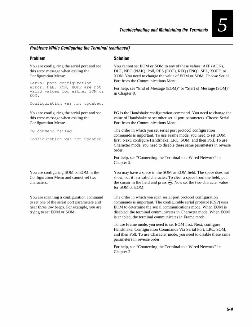
Nugget Co de 39 Troubleshooting and Maintaining the Terminals
5-9
5Problems While Configuring the Terminal (continued)
Problem Solution
You are configuring the serial port and seethis error message when exiting theConfiguration Menu:
Serial port configurationerror. DLE, XON, XOFF are notvalid values for either SOM orEOM.
Configuration was not updated.
You cannot set EOM or SOM to any of these values: AFF (ACK),DLE, NEG (NAK), Poll, RES (EOT), REQ (ENQ), SEL, XOFF, orXON. You need to change the value of EOM or SOM. Choose SerialPort from the Communications Menu.
For help, see “End of Message (EOM)” or “Start of Message (SOM)”in Chapter 8.
You are configuring the serial port and seethis error message when exiting theConfiguration Menu:
PG command failed.
Configuration was not updated.
PG is the Handshake configuration command. You need to change thevalue of Handshake or set other serial port parameters. Choose SerialPort from the Communications Menu.
The order in which you set serial port protocol configurationcommands is important. To use Frame mode, you need to set EOMfirst. Next, configure Handshake, LRC, SOM, and then Poll. To useCharacter mode, you need to disable these same parameters in reverseorder.
For help, see “Connecting the Terminal to a Wired Network” inChapter 2.
You are configuring SOM or EOM in theConfiguration Menu and cannot set twocharacters.
You may have a space in the SOM or EOM field. The space does notshow, but it is a valid character. To clear a space from the field, putthe cursor in the field and press �. Now set the two-character valuefor SOM or EOM.
You are scanning a configuration commandto set one of the serial port parameters andhear three low beeps. For example, you aretrying to set EOM or SOM.
The order in which you scan serial port protocol configurationcommands is important. The configurable serial protocol (CSP) usesEOM to determine the serial communications mode. When EOM isdisabled, the terminal communicates in Character mode. When EOMis enabled, the terminal communicates in Frame mode.
To use Frame mode, you need to set EOM first. Next, configureHandshake, Configuration Commands Via Serial Port, LRC, SOM,and then Poll. To use Character mode, you need to disable these sameparameters in reverse order.
For help, see “Connecting the Terminal to a Wired Network” inChapter 2.
Trakker Antares 241X Hand-Held Terminal User’s Manual Nugget Co de 39
5-10
Problems While Configuring the Terminal (continued)
Problem Solution
You see this error message when exiting theConfiguration Menu:
Commandnamecommand failed.
Remainder of configuration notupdated.
The two-character name (syntax) of the configuration command thatfailed is listed on the first line of the error message.
Check the command listed in the message. To find the command, usethe “Configuration Commands by Syntax” table in Appendix A. Makesure the command is set correctly for the options and networkcommunications you are using with the terminal. For help, seeChapter 8, “Configuration Command Reference.”
For example, you may see this message:
SScommand failed.
There may be a problem with the configuration due to a change madewith the Scanner Selection (SS) command.
You scan a configuration command, such asKeypad Caps Lock, and you hear three lowbeeps.
If you are working in the TRAKKER Antares 2400 Menu System, youcannot scan configuration commands. Use the Configuration Menu tochange the terminal’s configuration, or exit the menu system to scanconfiguration commands.
You scan a configuration command, such asKeypad Caps Lock, and nothing happens.
There are two possible solutions:
• You may have one or more reader commands disabled, such asChange Configuration, so that you cannot change theconfiguration. Enable all of the reader commands and try again.
• The terminal may be waiting for another command to complete theconfiguration change. If you started by scanning the EnterAccumulate command, you must finish the command by scanningthe Exit Accumulate command. For help, see Chapter 8,“Configuration Command Reference.”
Scan the Enable Override to temporarily enable all of the readercommands. When you are finished, remember to disable the overrideso that your data is not interpreted as a command.
Enable Override
*$+DC3**$+DC3*

Nugget Co de 39 Troubleshooting and Maintaining the Terminals
5-11
5Problems While Configuring the Terminal (continued)
Problem Solution
On the 2415, you scan a configurationcommand to set one of these parameters andhear three low beeps:
• Controller IP Address (UDP Plus)or Host IP Address (TCP/IP)
• Terminal IP Address• Default Router• Network Activate
If the Network Activate command is enabled (2.4 GHz RF networkenabled) and you are configuring the 2415, these IP addresses must bevalid.
To set these four parameters, follow these steps:
1. Disable the Network Activate (NA) configuration command.
2. Set the terminal IP address.
3. Set the controller IP address or the host IP address.
4. Set the default router address (if necessary).
5. Enable the Network Activate command.
You can change an IP address with the network enabled as long as itstill defines a valid network configuration.
You scan or enter an option for the ScannerSelection configuration command and youhear three low beeps.
You may have scanned or entered a Scanner Selection command thatdoes not apply to the type of scanner that you have installed. Tryscanning or entering the Scanner Selection command again and selectan option for the type of module you have installed.
Trakker Antares 241X Hand-Held Terminal User’s Manual Nugget Co de 39
5-12
2415 Will Not Communicate With RF Network DevicesIf you cannot get the 2415 to communicate with other devices in the 2.4 GHz RFnetwork, check these possible problems.
Problem Solution
The Connect LED is off. The 2415 is notcommunicating with the access point.
The 2415 is not connected to the access point. Make sure the accesspoint is turned on and operating. You may also be using the terminalout of range of an access point. Try moving closer to an access point tore-establish communications.
The Network Activate command may be disabled. Make sure theNetwork Activate command is enabled. Use the TRAKKER Antares2400 Menu System or scan the Network Activate command to enablethe 2.4 GHz RF network and turn on the radio. For help, see “NetworkActivate” in Chapter 8.
Make sure the 2415 is configured correctly for your network. In a 2.4GHz OpenAir network, the domain and the security ID on the terminalmust match the values set for all access points the terminal maycommunicate with. In an IEEE 802.11 DS network, the network nameon the terminal must match the values set for all access points theterminal may communicate with. For help, see “Connecting the 2415to an RF Network” in Chapter 2.
If you are within range of an access point, the Network Activatecommand is enabled, and the Connect LED is still off, you may have adefective radio card. For help, contact your local Intermec servicerepresentative.
The Connect LED blinks. In a UDP Plus network, the terminal is communicating with an accesspoint, but it is not connected to the DCS 300. You may need to checkthe 2415 configuration, or make sure the DCS 300 is running and thatdata collection is started.
Each device in the 2.4 GHz RF network must have a valid IP address.The IP addresses set on the terminal must match the addressesconfigured on the DCS 300 or host. For help, see “Connecting the2415 to an RF Network” in Chapter 2.
The 2415 is connected to the DCS 300 orhost computer and you move to a new site tocollect data. The Connect LED was on andnow begins to blink or turns off.
You may have gone out of range of an access point. Try moving closerto an access point or to a different location to re-establishcommunications. Once you are in range again, the Connect LED willturn on. Any data you collected while you were out of range will betransmitted over the network.
Nugget Co de 39 Troubleshooting and Maintaining the Terminals
5-13
52415 Will Not Communicate With RF Network Devices (continued)
Problem Solution
The Connect LED blinks and you see thismessage:
Unable to connect tocontroller. Error 102.
Unable to establish connectionto host. Session ended.
The 2415 is connected to the access point, but is trying to establishcommunications with the DCS 300 and the host computer. Make surethe terminal is correctly configured for your network. In a UDP Plusnetwork, make sure the DCS 300 is configured and data collection isstarted. In a TCP/IP network, make sure the host computer isconfigured and running.
If you have configured the network correctly, try shutting down andrestarting the DCS 300 to establish communications. You can also tryresetting the terminal. For help resetting the terminal, see “Bootingand Resetting the Terminal” later in this chapter.
The Connect LED is on, but the hostcomputer is not receiving any data from the2415.
In a UDP Plus network, there may be a problem with the connectionbetween the DCS 300 and the host computer. Check with yournetwork administrator or use the DCS 300 System Manual.
In a TCP/IP network, there may be a problem with the connectionbetween the access point and the host computer. Check with yournetwork administrator or use your access point user’s manual.
The Connect LED is on, but you cannotestablish a terminal emulation session withthe host computer.
There may be a problem with the host computer, a problem with theconnection between the DCS 300 and the host computer, or a problemwith the connection between the access point and the host computer.Check with your network administrator to make sure the host isrunning and allowing users to login to the system.
When you turn on the terminal after it wassuspended for awhile (10-15 minutes orlonger), the terminal can no longer send orreceive messages over the network.
The host may have deactivated or lost your current terminal emulationsession. In a TCP/IP direct connect network, you need to turn off the“Keep Alive” message (if possible) from the host so that the TCPsession is maintained while a terminal is suspended.
Trakker Antares 241X Hand-Held Terminal User’s Manual Nugget Co de 39
5-14
Problems Transmitting Data Through the Serial PortIf you are having problems sending or receiving data through the integrated I/O port onthe terminal, check these possible problems:
• Make sure the terminal is connected to the PC, host computer, or RS-232 serialdevice using the proper cable.
For help, see Appendix A, “Terminal Specifications and Other Helpful Information.”
• If the terminal is in a communications dock, make sure that the communications dockis connected to the serial device using the proper cable.
For help, see Appendix A, “Terminal Specifications and Other Helpful Information”or the Trakker Antares TD2410 Communications Dock Quick Reference Guide.
• Make sure the terminal’s serial port parameters are configured to match the serialport configuration on the PC, host computer, or serial device.
For help, see “Connecting the Terminal to a Wired Network” in Chapter 2.

Nugget Co de 39 Troubleshooting and Maintaining the Terminals
5-15
5Problems Transmitting Data Through the DCS 300
If you have a problem while running the application on the terminal in a UDP Plusnetwork, check these possible communications problems.
Problem Solution
Transaction Buffer Full. The buffer holding transactions to be sent to the DCS 300 is full. Stopcollecting data with this terminal. Make sure the terminal iscommunicating with the DCS 300 and let the terminal send all thetransactions in the buffer before you continue collecting data.
Sending Buffer Transactions. This is an information message to tell you that buffered transactionsare now being sent to the DCS 300. You can begin collecting dataagain once the message clears.
Transaction Aborted. The transaction just sent to the DCS 300 was not received. Trysending the transaction again.
Transmit Error XX, press Enter. There is an error transmitting data to the DCS 300. XX represents thestatus code error. Note the error code listed in the message and contactyour local Intermec service representative for help. Press 8 to continue.
Receive Error XX, press Enter. There is an error receiving data from the DCS 300. XX represents thestatus code error. Note the error code listed in the message and contactyour local Intermec service representative for help. Press 8 to continue.
Shutting down. The DCS 300 is shutting down. You may continue collecting data andbuffer the transactions in the terminal until the DCS 300 starts again,or stop collecting data with the terminal.
Controller Shutdown. The DCS 300 has shut down. You may continue collecting data andbuffer the transactions in the terminal until the DCS 300 starts again,or stop collecting data with the terminal.

Trakker Antares 241X Hand-Held Terminal User’s Manual Nugget Co de 39
5-16
Bar Code Labels Will Not ScanIf you cannot scan bar code labels or you are having problems with the scan module,check these possible problems.
Problem Solution
The terminal is turned off. Make sure the terminal is turned on. Press : to turn on the terminal.
You cannot see a red beam of light from thescanner when you press the Scan button andaim the scanner at a bar code label.
There are two possible problems:
• You may be too far away from the bar code label. Try movingcloser to the bar code label and scan it again.
• You may be scanning the bar code label “straight on.” Trychanging the scanning angle until the laser beam is the brightest.This is the best scanning angle.
You can test the effective range of the scanner. Move within 2 feet of awall and test the scanner. You need to be within the scanning range toscan bar code labels. For help on scanning distances, see “Physical andEnvironmental Specifications” in Appendix A.
When you release the Scan button, the GoodRead LED does not turn off.
The Good Read LED will remain on if you configure the terminal touse edge triggering. If you configure the terminal for level triggeringand the Good Read LED remains on, there may be a problem. Pressthe Scan button again without scanning a bar code label. If the LED isstill on, contact your local Intermec service representative.
You have an input device attached to theterminal and it cannot read any bar codelabels.
You may not be using an input device that is supported with theterminal. Make sure you are using one of the supported input devices
The input device attached to the terminaldoes not appear to work well or read bar codelabels very quickly.
Try setting the Scanner Selection command to the specific input deviceyou have attached. Check the bar code symbologies you have enabledon the terminal. Enable only the symbologies that you are using.

Nugget Co de 39 Troubleshooting and Maintaining the Terminals
5-17
5Bar Code Labels Will Not Scan (continued)
Problem Solution
The scanner will not read the bar code label. Try one of these solutions:
• Make sure you aim the scanner beam so it crosses the entire barcode label in one pass.
• The angle you are scanning the bar code label may not be workingwell, or you may be scanning the label “straight on.” Try scanningthe bar code label again, but vary the scanning angle.
• The bar code label print quality may be poor or unreadable. Tocheck the quality of the bar code label, try scanning a bar codelabel that you know scans. Compare the two bar code labels to seeif the bar code quality is too low. You may need to replace the labelthat you cannot scan.
• Make sure the bar code symbology you are scanning is enabled.Use the TRAKKER Antares 2400 Menu System to check thesymbologies. On the Symbologies Menu, each symbology that isenabled has an asterisk (*) next to the name of the symbology. Ifyour bar code symbology is disabled, enable it and then tryscanning the bar code label again.
• Make sure that the application you are running on the terminal isexpecting input from a bar code. You may need to type thisinformation instead of scanning it.
The scanner does not read the bar code labelsquickly, or the scanning beam seems to befaint or obscured.
The scanner window may be dirty. Clean the window with a solutionof ammonia and water. Wipe dry. Do not allow abrasive material totouch the window.

Trakker Antares 241X Hand-Held Terminal User’s Manual Nugget Co de 39
5-18
Booting and Resetting the TerminalYou seldom need to boot or reset the terminal. When you boot the terminal, it runsthrough power-on self test (POST) to test each major subsystem. The terminal uses theconfiguration currently saved in flash memory. Once the terminal is finished booting,your application appears on the screen.
You only need to reset the terminal when the terminal or an application are locked up andwill not respond. The terminal also boots and resets after a firmware upgrade or if youremove the battery pack for more than 15 minutes and the backup power source runs out.The next instructions explain how you boot and reset the terminal.
Booting the TerminalYou can boot the terminal using these two methods:
• Configure the : key to boot the terminal when you turn on the terminal.
• Use the Boot Menu.
Booting the Terminal on ResumeWhen you press : to turn off the terminal, it turns off and goes into Suspend mode.When you press : to turn on the terminal, it resumes or boots depending on the terminalconfiguration.
Use the Resume Execution configuration command to configure the : key:
Resume Execution Not Allowed Configures the terminal to boot and restart yourapplication each time you press : to turn on the terminal. Use this option if you want torestart your application every time you turn on the terminal.
Resume Execution Allowed Configures the terminal to resume exactly where it waswhen you turned off the terminal. Use this option to resume working each time you turnon the terminal.
You can configure the Resume Execution command by using the TRAKKER Antares2400 Menu System or by scanning these bar code labels. For help, see “ResumeExecution” in Chapter 8.
Resume Execution Not Allowed Resume Execution Allowed
*$+ER0* *$+ER1**$+ER0* *$+ER1*

Nugget Co de 39 Troubleshooting and Maintaining the Terminals
5-19
5Using the Boot MenuThe Boot menu appears after you
• reset the terminal.
• remove the battery pack and wait longer than 15 minutes to install a charged batterypack. This procedure also performs a destructive reset, which can have unpredictableresults.
• upgrade the firmware. For help, see “Upgrading the Firmware” later in this chapter.
BOOT MENU 1 - Boot System 2 - Run Loader 3 - Power Down POWER DOWN IN 60 SEC 241XU058.eps
The Boot Menu contains these commands:
Boot System If you did remove the batteries, make sure you install a charged mainbattery pack or the terminal will not turn on. Press � to boot the terminal. Once theterminal is finished booting, your application appears on the screen.
Run Loader Press � to load the terminal firmware. To upgrade or load the firmware,you should use the Firmware Upgrade option in the TRAKKER Antares 2400 MenuSystem. For help, see “Upgrading the Firmware” later in this chapter.
Power Down Press � to turn off the terminal. When you turn on the terminal, the BootMenu screen appears again if POST passes.

Trakker Antares 241X Hand-Held Terminal User’s Manual Nugget Co de 39
5-20
Resetting the TerminalIf the terminal or application is locked up and the terminal will not respond to any keysequences, try the following steps in order:
1. Press : to turn off the terminal. Press : to turn on the terminal.
2. Use the TRAKKER Antares 2400 Menu System to reboot the terminal.
a. Press � 8 0 � ) or press � 8 � � � to enter the TRAKKER Antares2400 Menu System.
b. Choose System Menu and then Upgrade Firmware.
c. Choose OK, then YES, then press �. The Boot Menu appears.
d. Press � to boot the terminal.
3. Scan the Reset Firmware label to restart the firmware and application.
Reset Firmware
*-.**-.*
If the terminal or application still will not respond, reset the terminal.
To reset the terminal
• Scan the Boot Terminal label to reboot the terminal.
Boot Terminal
*-.1**-.1*
Or if the terminal will not scan, you can perform a destructive reset. A destructive resetcan have unpredictable results.
1. If possible, press : to turn off the terminal.
2. Press and hold the : key for approximately 12 seconds. The Good Read LED blinksonce and the terminal turns off.
3. Press : to turn on the terminal. The Boot Menu appears. Refer to the illustration onthe previous page.
4. Press � to boot the terminal. Once the terminal has finished booting, yourapplication appears.
5. Set the time and date. For help using the TRAKKER Antares 2400 Menu System,see “Configuring the Terminal With the Menu System” in Chapter 3.

Nugget Co de 39 Troubleshooting and Maintaining the Terminals
5-21
5Cleaning the Scanner Window and Terminal Screen
The terminals are built for use in a light industrial working environment. You may needto perform these minor maintenance tasks to keep the terminal in good working order:
• Clean the scanner window.
• Clean the terminal screen.
Clean the scanner window and terminal screen as often as needed for the environment inwhich you are using the terminal.
To clean the scanner window and terminal screen
1. Press : to turn off the terminal.
2. Use a solution of ammonia and water.
3. Dip a clean towel or rag in the ammonia solution and wring out the excess solution.Wipe off the scanner window and terminal screen. Do not allow any abrasivematerial to touch these surfaces.
4. Wipe dry.

Trakker Antares 241X Hand-Held Terminal User’s Manual Nugget Co de 39
5-22
Upgrading the TerminalThis section explains how to upgrade the firmware on the terminal and how to loaddouble-byte fonts, if you choose to order them after you receive your terminal.
You can also upgrade the terminal for:
• TE 2000 (new releases)
• dcBrowser Client
For pricing and availability, check with your local Intermec representative.
Upgrading the FirmwareNote: When you upgrade the firmware, you restore the terminal’s default configuration.You will need to set the primary network communications parameters on the 2415 toreestablish communications with other devices in the RF network. You also need to resetthe serial port parameters to communicate with another device through the serial port.
To order a firmware upgrade kit, contact your local Intermec service representative. Eachkit comes with the latest firmware version, the default applications, the DOS firmwareupgrade utility, a README.TXT file, and a WHATSNEW.TXT file.
Note: You can also upgrade the firmware on one or more 2415s using the DCS 300firmware upgrade utility. For help, see the DCS 300 System Manual.
To upgrade the firmware using the DOS utility
Note: Before you can upgrade the firmware, open the MS-DOS window. Then, open theMS-DOS Prompt Properties dialog box. In the Memory tab, set the Initial Environmentfield to 4096. Close the MS-DOS window and re-open it.
1. Connect the terminal to your PC. For help connecting the terminal, see “Using SerialCommunications on the Terminals” in Chapter 2.
2. Create a new directory on your PC.
3. Copy these five upgrade files to the directory that you created in Step 2:
• INSTALL.BAT
• INSTALL.INF
• TKANTxxx.EXE, where xxx is the firmware revision number.
• README.TXT
• WHATSNEW.TXT
4. Access the MS-DOS window.

Nugget Co de 39 Troubleshooting and Maintaining the Terminals
5-23
55. Change to the directory where the upgrade files are located.
6. Type:
INSTALL
The batch file explodes the TKANTxxx.EXE file to a new directory. This newdirectory contains all the files you need to perform an upgrade.
7. On the terminal, press � 8 0 � ) or press � 8 � � � or scan this bar codelabel:
Enter Test and Service Mode
*..-.**..-.*
The Main Menu appears.
8. Choose System Menu and press 8. The System Menu appears.
SYSTEM MENU File Manager Load Default Values Set Time and Date Store Configuration Upgrade Firmware ⁄ _` Select item [Enter] Next screen [F1] Help [Esc] Exit
241XU044.eps
9. Choose Upgrade Firmware and press 8. The Upgrade Firmware screen appears.
UPGRADE FIRMWARE Upgrade terminal
firmware? Make sure the terminal is connected to a host computer through the
optical adapter.
241XU060.eps
OK CANCEL

Trakker Antares 241X Hand-Held Terminal User’s Manual Nugget Co de 39
5-24
10. Choose OK to continue. The next screen appears.
Are you sure you want to continue? Selecting YES will upgrade and replace all of the terminal's firmware. Selecting NO will exit without upgrading firmware.
241XU091.eps
YES NO
11. Choose Yes to continue and upgrade the firmware. The terminal reboots and thendisplays the Loader Waiting screen.
Note: If you reach the Loader Waiting screen and cannot upgrade or continue, press� once or : twice to exit without upgrading the firmware. The Boot Menu appears.Press � to boot the terminal and continue.
12. On your PC in the MS-DOS window, change to the directory that contains theupgrade files in Step 6.
13. Type:
UPGRADE
A menu appears asking you to select a communications port.
14. Choose 1 to select COM1. A menu appears asking you to select a download speed.
15. Choose a download speed. A menu appears asking you to select which protocol stackto use.
16. Choose a protocol stack. A menu appears asking you to select the communicationhardware for your terminal.
17. Choose the communication hardware. The Loader screen appears and beginsdownloading the firmware and application to the terminal.
18. When you are done upgrading the firmware, the terminal returns to its defaultconfiguration. You will need to reconfigure the terminal. For help, see “Using theTerminal for the First Time” in Chapter 1.
If you are using Windows NT, follow the above procedure through Step 12. Print theUPGRADE.BAT file. Identify the numbers that are associated with the menu selectionsin Steps 14 through 17. When you get to Step 13, type:
UPGRADE X X X X
where the Xs represent the menu selection numbers.
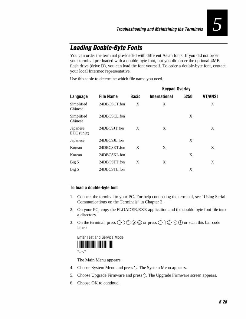
Nugget Co de 39 Troubleshooting and Maintaining the Terminals
5-25
5Loading Double-Byte FontsYou can order the terminal pre-loaded with different Asian fonts. If you did not orderyour terminal pre-loaded with a double-byte font, but you did order the optional 4MBflash drive (drive D), you can load the font yourself. To order a double-byte font, contactyour local Intermec representative.
Use this table to determine which file name you need.
Keypad Overlay
Language File Name Basic International 5250 VT/ANSI
SimplifiedChinese
24DBCSCT.fon X X X
SimplifiedChinese
24DBCSCL.fon X
JapaneseEUC (unix)
24DBCSJT.fon X X X
Japanese 24DBCSJL.fon X
Korean 24DBCSKT.fon X X X
Korean 24DBCSKL.fon X
Big 5 24DBCSTT.fon X X X
Big 5 24DBCSTL.fon X
To load a double-byte font
1. Connect the terminal to your PC. For help connecting the terminal, see “Using SerialCommunications on the Terminals” in Chapter 2.
2. On your PC, copy the FLOADER.EXE application and the double-byte font file intoa directory.
3. On the terminal, press � 8 0 � ) or press � 8 � � � or scan this bar codelabel:
Enter Test and Service Mode
*..-.**..-.*
The Main Menu appears.
4. Choose System Menu and press 8. The System Menu appears.
5. Choose Upgrade Firmware and press 8. The Upgrade Firmware screen appears.
6. Choose OK to continue.

Trakker Antares 241X Hand-Held Terminal User’s Manual Nugget Co de 39
5-26
7. Choose Yes to continue and upgrade the firmware. The terminal reboots and thendisplays the Loader Waiting screen.
Note: If you reach the Loader Waiting screen and cannot upgrade or continue, press� once or : twice to exit without upgrading the firmware. The Boot Menu appears.Press � to boot the terminal and continue.
8. On your PC, access the MS-DOS window.
9. At the prompt, change to the directory that contains the double-byte font.
10. Type:
FLOADER / COM1 / baudrate filename .FON
where:
baudrate is b9600, b19200, b38400, b57600, or b115200
filename is one of the file names in the table.

Nugg Co de 39
Running Diagnostics
6

Nugg Co de 39
6-2
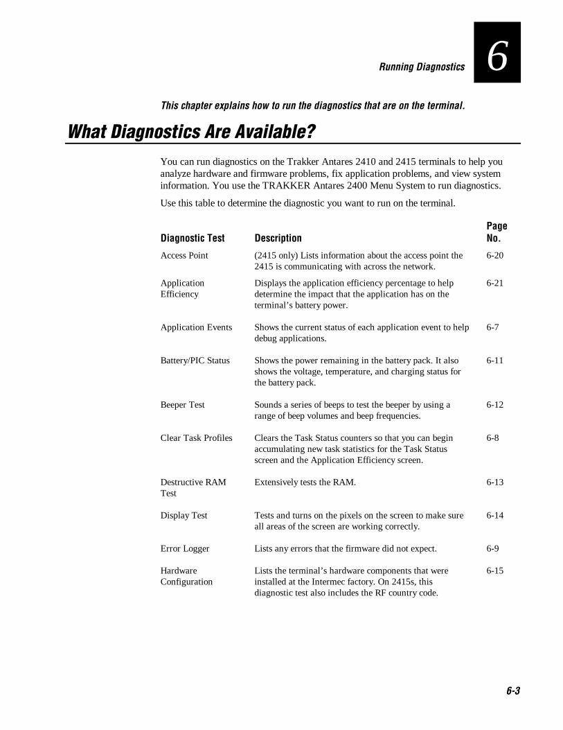
Nugg Co de 39 Running Diagnostics
6-3
6This chapter explains how to run the diagnostics that are on the terminal.
What Diagnostics Are Available?You can run diagnostics on the Trakker Antares 2410 and 2415 terminals to help youanalyze hardware and firmware problems, fix application problems, and view systeminformation. You use the TRAKKER Antares 2400 Menu System to run diagnostics.
Use this table to determine the diagnostic you want to run on the terminal.
Diagnostic Test DescriptionPageNo.
Access Point (2415 only) Lists information about the access point the2415 is communicating with across the network.
6-20
ApplicationEfficiency
Displays the application efficiency percentage to helpdetermine the impact that the application has on theterminal’s battery power.
6-21
Application Events Shows the current status of each application event to helpdebug applications.
6-7
Battery/PIC Status Shows the power remaining in the battery pack. It alsoshows the voltage, temperature, and charging status forthe battery pack.
6-11
Beeper Test Sounds a series of beeps to test the beeper by using arange of beep volumes and beep frequencies.
6-12
Clear Task Profiles Clears the Task Status counters so that you can beginaccumulating new task statistics for the Task Statusscreen and the Application Efficiency screen.
6-8
Destructive RAMTest
Extensively tests the RAM. 6-13
Display Test Tests and turns on the pixels on the screen to make sureall areas of the screen are working correctly.
6-14
Error Logger Lists any errors that the firmware did not expect. 6-9
HardwareConfiguration
Lists the terminal’s hardware components that wereinstalled at the Intermec factory. On 2415s, thisdiagnostic test also includes the RF country code.
6-15

Trakker Antares 241X Hand-Held Terminal User’s Manual Nugg Co de 39
6-4
Diagnostic Tests (continued)
Diagnostic Test DescriptionPageNo.
Keypad Test Shows the hexadecimal, decimal, and scan code value forany key or key combination on the keypad.
6-16
Malloc ApplicationInformation
Shows how memory is allocated and used by the currentapplication.
6-22
Malloc FirmwareInformation
Shows how memory is allocated and used in the terminalfirmware.
6-23
Radio Test (2415 only) Tests the radio to make sure it is working. 6-17
Scanner Test Tests the laser scanner to make sure it is working. 6-18
Serial PortLoopback
Verifies that the hardware for the RS-232 serial port isfunctioning correctly.
6-19
Serial Port Test Tests serial communications between the terminal andthe host computer or serial device.
6-24
Subsystem Versions Lists the version of each major firmware subsystemloaded on the terminal.
6-25
Task Status Shows the task name, stack, the percentage of time eachsubsystem has been running, and the stack usage.
6-10

Nugg Co de 39 Running Diagnostics
6-5
6Running Diagnostics From the Menu SystemThe TRAKKER Antares 2400 Menu System is a menu-driven application that lets youconfigure the terminal, view system information, and run diagnostics. You can access theTRAKKER Antares 2400 Menu System and run diagnostics while running anyapplication.
To run diagnostics from the TRAKKER Antares 2400 Menu System
1. Press � 8 0 � ) or press � 8 � � � or scan this bar code label:
Enter Test and Service Mode
*..-.**..-.*
The Main Menu appears.
2. Choose the Diagnostics Menu and press 8. The Diagnostics Menu appears.
DIAGNOSTICS MENU Software Diagnostics Hardware Diagnostics System Diagnostics ⁄ _` Select item [Enter] Next screen [F1] Help [Esc] Exit
241XU062.eps
The Diagnostics Menu contains these commands:
Software Diagnostics Lets you run software diagnostics to help analyze softwareproblems on the terminal. For example, you can view the Error Logger file to viewsystem errors.
Hardware Diagnostics Lets you run hardware diagnostics to help analyze hardwareproblems on the terminal. For example, you can check the power remaining and thecondition of the battery pack.
System Diagnostics Lets you run system diagnostics to help analyze network,system, or application problems on the terminal. For example, you can rundiagnostics to check the communications between the 2415 and the access point.
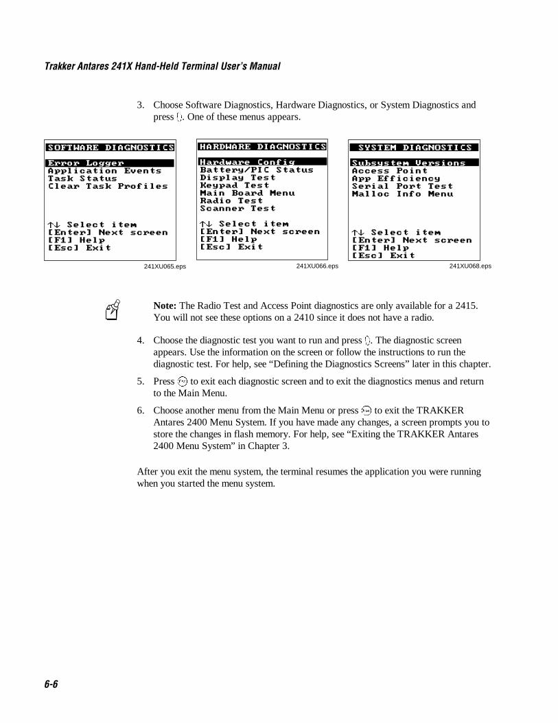
Trakker Antares 241X Hand-Held Terminal User’s Manual Nugg Co de 39
6-6
3. Choose Software Diagnostics, Hardware Diagnostics, or System Diagnostics andpress 8. One of these menus appears.
SOFTWARE DIAGNOSTICS Error Logger Application Events Task Status Clear Task Profiles _` Select item [Enter] Next screen [F1] Help [Esc] Exit
241XU065.eps
HARDWARE DIAGNOSTICS Hardware Config Battery/PIC Status Display Test Keypad Test Main Board Menu Radio Test Scanner Test _` Select item [Enter] Next screen [F1] Help [Esc] Exit
241XU066.eps
SYSTEM DIAGNOSTICS Subsystem Versions Access Point App Efficiency Serial Port Test Malloc Info Menu _` Select item [Enter] Next screen [F1] Help [Esc] Exit
241XU068.eps
Note: The Radio Test and Access Point diagnostics are only available for a 2415.You will not see these options on a 2410 since it does not have a radio.
4. Choose the diagnostic test you want to run and press 8. The diagnostic screenappears. Use the information on the screen or follow the instructions to run thediagnostic test. For help, see “Defining the Diagnostics Screens” later in this chapter.
5. Press � to exit each diagnostic screen and to exit the diagnostics menus and returnto the Main Menu.
6. Choose another menu from the Main Menu or press � to exit the TRAKKERAntares 2400 Menu System. If you have made any changes, a screen prompts you tostore the changes in flash memory. For help, see “Exiting the TRAKKER Antares2400 Menu System” in Chapter 3.
After you exit the menu system, the terminal resumes the application you were runningwhen you started the menu system.
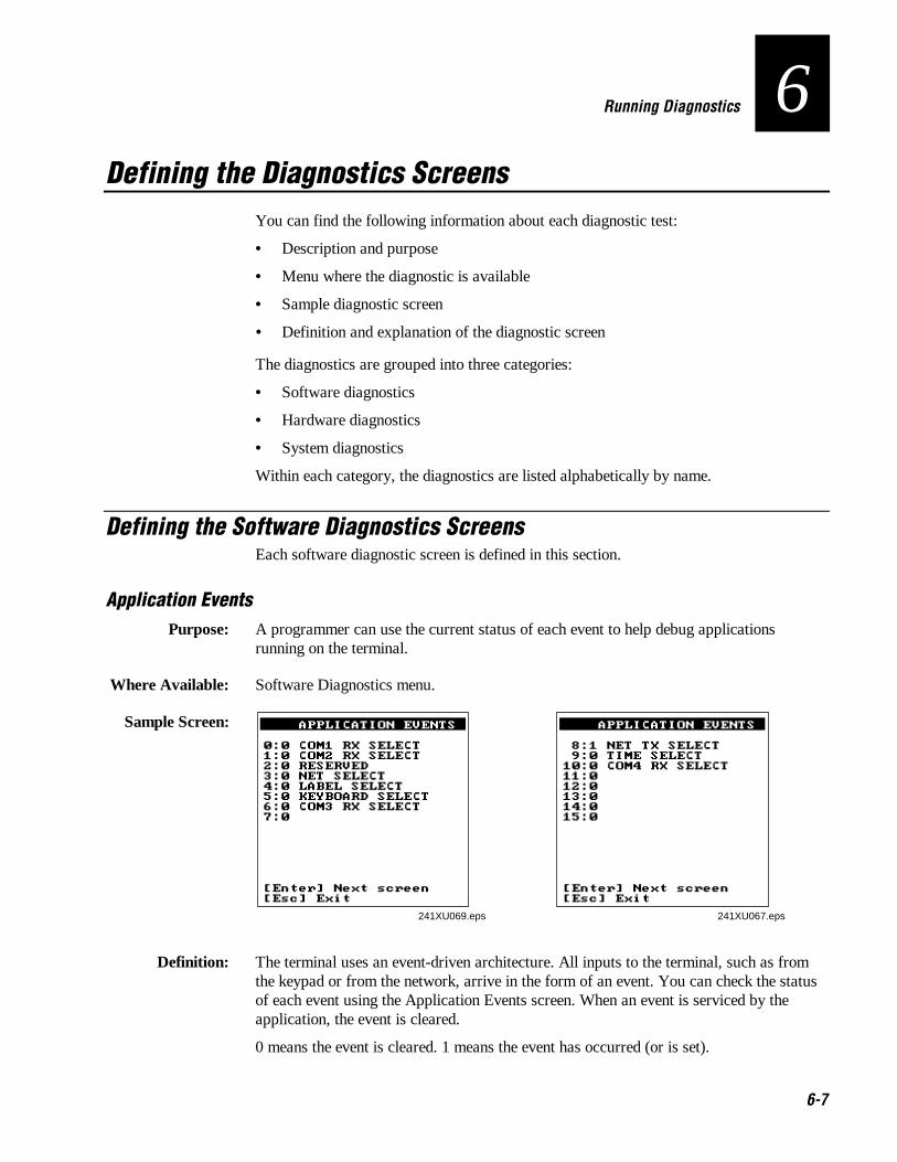
Nugg Co de 39 Running Diagnostics
6-7
6Defining the Diagnostics Screens
You can find the following information about each diagnostic test:
• Description and purpose
• Menu where the diagnostic is available
• Sample diagnostic screen
• Definition and explanation of the diagnostic screen
The diagnostics are grouped into three categories:
• Software diagnostics
• Hardware diagnostics
• System diagnostics
Within each category, the diagnostics are listed alphabetically by name.
Defining the Software Diagnostics ScreensEach software diagnostic screen is defined in this section.
Application EventsPurpose: A programmer can use the current status of each event to help debug applications
running on the terminal.
Where Available: Software Diagnostics menu.
Sample Screen:
241XU069.eps
APPLICATION EVENTS 0:0 COM1 RX SELECT 1:0 COM2 RX SELECT 2:0 RESERVED 3:0 NET SELECT 4:0 LABEL SELECT 5:0 KEYBOARD SELECT 6:0 COM3 RX SELECT 7:0 [Enter] Next screen [Esc] Exit
241XU067.eps
APPLICATION EVENTS 8:1 NET TX SELECT 9:0 TIME SELECT 10:0 COM4 RX SELECT 11:0 12:0 13:0 14:0 15:0 [Enter] Next screen [Esc] Exit
Definition: The terminal uses an event-driven architecture. All inputs to the terminal, such as fromthe keypad or from the network, arrive in the form of an event. You can check the statusof each event using the Application Events screen. When an event is serviced by theapplication, the event is cleared.
0 means the event is cleared. 1 means the event has occurred (or is set).

Trakker Antares 241X Hand-Held Terminal User’s Manual Nugg Co de 39
6-8
Clear Task ProfilesPurpose: Clears the task profile counters so that you can begin accumulating statistics on the
firmware subsystem tasks from a known point in time.
Where Available: Software Diagnostics menu
Sample Screen:
241XU070.eps
CLEAR TASK PROFILES Operating system task profile counters have been cleared. [Esc] Exit
Definition: When you select the Clear Task Profiles option, the terminal clears the %Time field onthe Task Status screen. It also resets all counters that are used to calculate theApplication Efficiency screen.

Nugg Co de 39 Running Diagnostics
6-9
6Error Logger
Purpose: You can use the Error Logger screen to display any errors that the system detected whileyou were using the terminal. For help solving an error, contact your local Intermecservice representative.
Where Available: Software Diagnostics menu
Sample Screen:
241X064.eps
ERROR LOGGER Current Time:231912 Time Err# Address 024401 0003 90000548 024359 0002 90000548 024358 0001 90000548 [Enter] Next screen [Esc] Exit
Definition: The Error Logger screen shows the last 30 errors. Press @ to see the next screen oferrors. The first column displays the time in HHMMSS. The second column displays theerror number. The third column displays the internal firmware address, which helpsidentify why the error occurred.
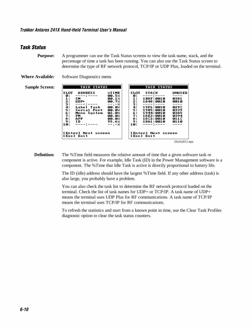
Trakker Antares 241X Hand-Held Terminal User’s Manual Nugg Co de 39
6-10
Task StatusPurpose: A programmer can use the Task Status screens to view the task name, stack, and the
percentage of time a task has been running. You can also use the Task Status screen todetermine the type of RF network protocol, TCP/IP or UDP Plus, loaded on the terminal.
Where Available: Software Diagnostics menu
Sample Screen: TASK STATUS SLOT ADDRESS %TIME 0: ----:---- 00.5% 1: SM 00.1% 2: UDP+ 00.7% 3: ----:---- --.-% 4: Label Task 00.0% 5: Serial Port 00.0% 6: Menu System 02.0% 7: PM 00.0% 8: APP 00.0% 9: ID 95.6% 10: ----:---- --.-% [Enter] Next screen [Esc] Exit
241XU071.eps
TASK STATUS SLOT STACK UNUSED 0: ----:---- ---- 1: 1B8F:0010 0381 2: 1A48:0010 0010 3: ----:---- ---- 4: 19F6:0010 029C 5: 19B5:0010 0339 6: 1944:0010 03A5 7: 18E3:0010 0394 8: 18C2:0010 011C 9: 18A1:0010 0110 10: ----:---- ---- [Enter] Next screen [Esc] Exit
Definition: The %Time field measures the relative amount of time that a given software task orcomponent is active. For example, Idle Task (ID) in the Power Management software is acomponent. The %Time that Idle Task is active is directly proportional to battery life.
The ID (idle) address should have the largest %Time field. If any other address (task) isalso large, you probably have a problem.
You can also check the task list to determine the RF network protocol loaded on theterminal. Check the list of task names for UDP+ or TCP/IP. A task name of UDP+means the terminal uses UDP Plus for RF communications. A task name of TCP/IPmeans the terminal uses TCP/IP for RF communications.
To refresh the statistics and start from a known point in time, use the Clear Task Profilesdiagnostic option to clear the task status counters.
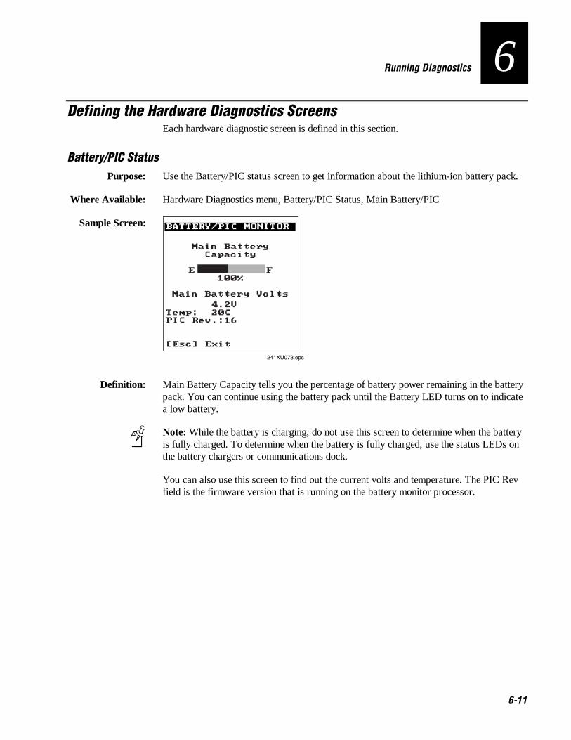
Nugg Co de 39 Running Diagnostics
6-11
6Defining the Hardware Diagnostics Screens
Each hardware diagnostic screen is defined in this section.
Battery/PIC StatusPurpose: Use the Battery/PIC status screen to get information about the lithium-ion battery pack.
Where Available: Hardware Diagnostics menu, Battery/PIC Status, Main Battery/PIC
Sample Screen: BATTERY/PIC MONITOR
241XU073.eps
Main Battery Capacity
E F
100%
Main Battery Volts
4.2V Temp: 20C PIC Rev.:16 [Esc] Exit
Definition: Main Battery Capacity tells you the percentage of battery power remaining in the batterypack. You can continue using the battery pack until the Battery LED turns on to indicatea low battery.
Note: While the battery is charging, do not use this screen to determine when the batteryis fully charged. To determine when the battery is fully charged, use the status LEDs onthe battery chargers or communications dock.
You can also use this screen to find out the current volts and temperature. The PIC Revfield is the firmware version that is running on the battery monitor processor.

Trakker Antares 241X Hand-Held Terminal User’s Manual Nugg Co de 39
6-12
Beeper TestPurpose: You can test the terminal beeper to make sure the entire beep volume range and beep
frequency range are available and working correctly. The Beeper Test can also help youdistinguish the different beep volumes to choose a level that you can hear in your workingenvironment.
Where Available: Choose the Main Board Menu from the Hardware Diagnostics menu.
Sample Screen:
241XU076.eps
BEEPER TEST SELECT BEEP TEST: (Hold down any key to stop test) 1-Frequency Up/Down 2-Volume Up/Down 3-Club 39 Jam 4-K. 622 [Esc] Exit
Definition: Press � to test the beep frequency range. The terminal will sound a series of beepsstarting from a low frequency beep through the range to a high frequency beep, and thenback to a low frequency beep.
Press � to test the beep volume. The terminal sounds a series of beeps from a quiet beepto a very loud beep. On the 241X, the quiet and normal beep volumes sound the same andthe loud and very loud beep volumes sound the same.
Tests 3 and 4 also test the beep volume and frequency by playing a short tune. If you donot hear any beeps during any of these tests, you may have a problem with the beeper orinternal speakers. For help, contact your local Intermec service representative.

Nugg Co de 39 Running Diagnostics
6-13
6Destructive RAM Test
Purpose: Use the Destructive RAM Test if you have any problems storing files on the RAM driveor running an application that uses RAM memory.
Where Available: Choose the Main Board Menu from the Hardware Diagnostics menu.
Sample Screen:
2421XU078.eps
DESTRUCTIVE RAM TEST The following test will cause the unit to reboot, causing loss of all RAM resident data. PROCEED? PRESS 'Y' to proceed... [Esc] Exit
Memory Test Passed Pass #: 00037 Press a key to Reboot Unit
Definition: Before you run this test, save your data. If you are running a TE application, end yourcurrent TE session. Press 5 to start the test. All data in RAM will be lost. The terminalstarts the RAM test and clears the screen. You hear a beep after a successful test of each64K block of data. After 15 beeps, a test pass is complete and the results appear. Thesample screen shows a successful test pass.
To run another test pass, do not press a key and the next test begins after a 5 secondpause. You may let the test continue and test the RAM several times to get a test overtime. To exit the test, press 8 once a test pass is complete. The terminal reboots andrestarts your application.
If an error is found, the Destructive RAM Test stops and displays the error address, thedata written to RAM, and the data read from RAM. Note this information and contactyour local Intermec service representative.
CautionIf the Destructive RAM Test fails, stop using the terminal. Contact your localIntermec service representative.
ConseilSi le test Destructive RAM échoue, veuillez ne plus utiliser le terminal. Contactez lereprésentant du service clientèle Intermec de votre région.

Trakker Antares 241X Hand-Held Terminal User’s Manual Nugg Co de 39
6-14
Display TestPurpose: Use the Display Test to make sure that every pixel on the terminal screen is working
correctly. For example, you may want to test the screen if you do not see completecharacters on the screen.
Where Available: Hardware Diagnostics menu
Sample Screen:
241XU080.eps
DISPLAY TEST [Enter] Next pattern [Esc] Exit
Definition: Press 8 to display each of the four patterns. After 5 seconds, the entire screen is filledwith the current test pattern. Press 8 to display the next pattern. The first two patternsappear as a shaded pattern and turn off every other pixel. The third pattern turns on everypixel and appears as a black square. The fourth pattern turns off every pixel and appearsas a clear square.
If any of these patterns do not display correctly, you may have a problem with the LCD.For help, contact your local Intermec service representative.

Nugg Co de 39 Running Diagnostics
6-15
6Hardware Configuration
Purpose: If you are discussing a problem with Intermec, you can use the Hardware Configurationscreen to tell the Intermec representative the exact version of hardware that was installedon the terminal at the Intermec factory. You can also use this screen to see the countrycode that is configured on the 2415.
Where Available: Hardware Diagnostics menu
Sample Screen:
HARDWARE CONFIG Digital IO : 255 Icon Led : 1 COM1 type : 1 COM2 type : 0 COM3 type : 0 COM4 type : 0 PCMCIA B Type: 0 PCMCIA B Rev : 0 [Enter] Next screen [Esc] Exit
HARDWARE CONFIG PCMCIA TYPE: 2 PCMCIA REV : 1 PCB Rev : 1 Product ID : 2415 Serial # : 123456789 [Enter] Next screen [Esc] Exit
241XU082.eps
HARDWARE CONFIG ASIC B : 0 Eeprom : 0 Flash Size : 0 [Enter] Next screen [Esc] Exit
HARDWARE CONFIG ŁCountry Code : USA (028)Ł Display Type : 0 Display Rev : 0 Display Cont : 32 Keypad Type : 0 Keypad Rev : 2 Keypad Table : 21 [Enter] Next screen [Esc] Exit
Definition: Press 8 to display the next screen of hardware information. If you are having a specificproblem with one system, such as the radio, note the hardware versions on the terminalbefore contacting your local Intermec service representative.
The country code information on the Hardware Configuration screen is only valid whenthe radio (Network Activate command) is enabled. If the radio is disabled, the countrycode information is not valid. For help, see “Network Activate” in Chapter 8.
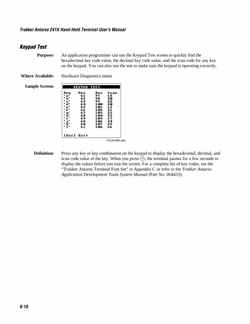
Trakker Antares 241X Hand-Held Terminal User’s Manual Nugg Co de 39
6-16
Keypad TestPurpose: An application programmer can use the Keypad Test screen to quickly find the
hexadecimal key code value, the decimal key code value, and the scan code for any keyon the keypad. You can also use the test to make sure the keypad is operating correctly.
Where Available: Hardware Diagnostics menu
Sample Screen:
241XU084.eps
KEYPAD TEST Key Hex Dec Scan 'a' 61 97 1E 'b' 62 98 30 'c' 63 99 2E 'd' 64 100 20 'e' 65 101 12 'f' 66 102 21 'g' 67 103 22 'h' 68 104 23 'i' 69 105 17 'j' 6A 106 24 'k' 6B 107 25 'l' 6C 108 26 [Esc] Exit
Definition: Press any key or key combination on the keypad to display the hexadecimal, decimal, andscan code value of the key. When you press �, the terminal pauses for a few seconds todisplay the values before you exit the screen. For a complete list of key codes, see the“Trakker Antares Terminal Font Set” in Appendix C or refer to the Trakker AntaresApplication Development Tools System Manual (Part No. 064433).
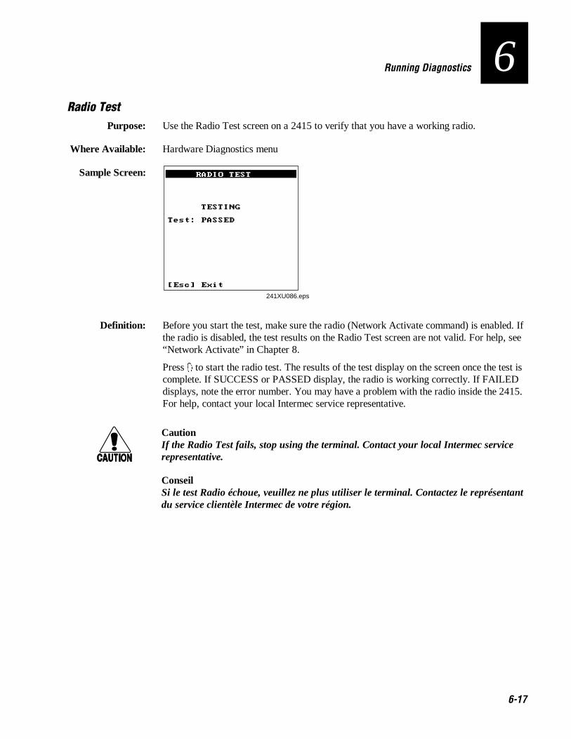
Nugg Co de 39 Running Diagnostics
6-17
6Radio Test
Purpose: Use the Radio Test screen on a 2415 to verify that you have a working radio.
Where Available: Hardware Diagnostics menu
Sample Screen:
241XU086.eps
RADIO TEST TESTING Test: PASSED [Esc] Exit
Definition: Before you start the test, make sure the radio (Network Activate command) is enabled. Ifthe radio is disabled, the test results on the Radio Test screen are not valid. For help, see“Network Activate” in Chapter 8.
Press 8 to start the radio test. The results of the test display on the screen once the test iscomplete. If SUCCESS or PASSED display, the radio is working correctly. If FAILEDdisplays, note the error number. You may have a problem with the radio inside the 2415.For help, contact your local Intermec service representative.
CautionIf the Radio Test fails, stop using the terminal. Contact your local Intermec servicerepresentative.
ConseilSi le test Radio échoue, veuillez ne plus utiliser le terminal. Contactez le représentantdu service clientèle Intermec de votre région.
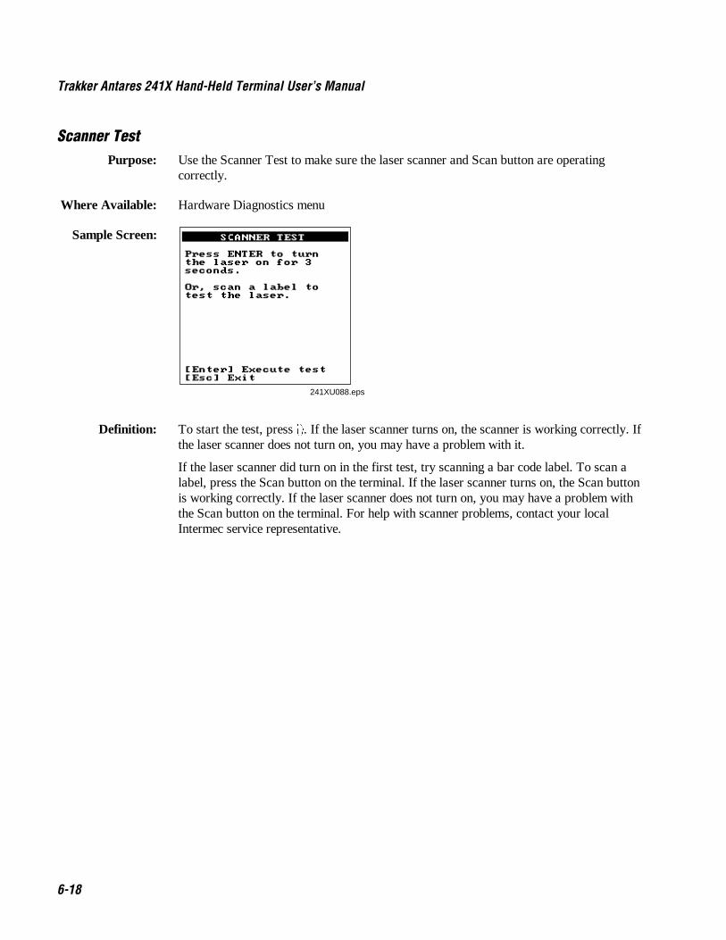
Trakker Antares 241X Hand-Held Terminal User’s Manual Nugg Co de 39
6-18
Scanner TestPurpose: Use the Scanner Test to make sure the laser scanner and Scan button are operating
correctly.
Where Available: Hardware Diagnostics menu
Sample Screen:
241XU088.eps
SCANNER TEST Press ENTER to turn the laser on for 3 seconds. Or, scan a label to test the laser. [Enter] Execute test [Esc] Exit
Definition: To start the test, press 8. If the laser scanner turns on, the scanner is working correctly. Ifthe laser scanner does not turn on, you may have a problem with it.
If the laser scanner did turn on in the first test, try scanning a bar code label. To scan alabel, press the Scan button on the terminal. If the laser scanner turns on, the Scan buttonis working correctly. If the laser scanner does not turn on, you may have a problem withthe Scan button on the terminal. For help with scanner problems, contact your localIntermec service representative.

Nugg Co de 39 Running Diagnostics
6-19
6Serial Port Loopback Test
Purpose: Use the Serial Port Loopback test to verify that the hardware for the serial port isfunctioning correctly. To run this diagnostic test, you must connect the terminal to a hostcomputer or other serial device via a special cable (Part No. 069589) or thecommunications dock.
Where Available: Choose the Main Board Menu from the Hardware Diagnostics menu.
Sample Screen:
241XU144.eps
SERIAL PORT LOOPBACK WAITING /CTS 0 COM Port : 1 Baud Rate : 38400 Parity : None Data Bits : 8 Echo RX Data on TX Echo /CTS on /RTS [Esc] Exit
Definition: The serial port test begins immediately. You may need to disconnect the terminal fromthe current session. If the serial port hardware is functioning correctly, the terminaldisplays WAITING. When the host computer or other serial devices are transmitting, theterminal displays RECEIVING. The Serial Port Loopback test uses the serialcommunications settings that are listed on the bottom half of the screen.
On the host, you can use a serial communications package to send data to the terminal. Ifthe terminal is communicating with the host, the data is echoed back. If there is aproblem, an error message appears on the terminal screen. The status information on thescreen is updated every 500 ms. For help with serial port errors, contact your localIntermec service representative.

Trakker Antares 241X Hand-Held Terminal User’s Manual Nugg Co de 39
6-20
Defining the System Diagnostics ScreensEach system diagnostic screen is defined in this section.
Access PointPurpose: Use the Access Point screen to get version and address information about the access point
the terminal is communicating with across the RF network. This diagnostic applies onlyto the 2415.
Where Available: System Diagnostics menu
Sample Screen:
241XU090.eps
ACCESS POINT Radio ROM Ver: V1.6EB Radio MAC Addr: 0020A6306510 Access Point Name: SHIPPING Access Point MAC: 0020A6301365 [Esc] Exit
Definition: The screen displays the radio ROM firmware version and the radio MAC (machine)address for the terminal. It also displays the access point name and the access pointMAC. If you have a problem with the radio or the connection to the access point, use theinformation on this screen to troubleshoot your network configuration.
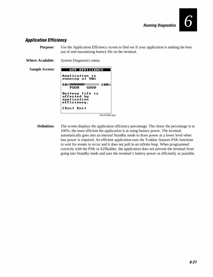
Nugg Co de 39 Running Diagnostics
6-21
6Application Efficiency
Purpose: Use the Application Efficiency screen to find out if your application is making the bestuse of and maximizing battery life on the terminal.
Where Available: System Diagnostics menu
Sample Screen: APP EFFICIENCY Subsystem Versions Application is running at 90% 80% 100% POOR GOOD Battery life is affected by application efficiency. [Esc] Exit
241XU092.eps
Definition: The screen displays the application efficiency percentage. The closer the percentage is to100%, the more efficient the application is at using battery power. The terminalautomatically goes into an internal Standby mode to draw power at a lower level whenless power is required. An efficient application uses the Trakker Antares PSK functionsto wait for events to occur and it does not poll in an infinite loop. When programmedcorrectly with the PSK or EZBuilder, the application does not prevent the terminal fromgoing into Standby mode and uses the terminal’s battery power as efficiently as possible.

Trakker Antares 241X Hand-Held Terminal User’s Manual Nugg Co de 39
6-22
Malloc Application InformationPurpose: A programmer or application developer can use the Malloc Application Information
screen to see how memory is allocated and used by the current application.
Where Available: Choose the Malloc Info Menu from the System Diagnostics menu.
Sample Screen:
241XU094.eps
APPLICATION Total Free: 0000064656 Largest Free: 0000064656 Fragments: 00001 Allocated Blocks: 00001 OK
Definition: The screen displays the memory allocation used by the application. You can view thetotal free memory, the largest block of free memory, number of memory fragments, andthe total number of allocated blocks of memory. You can use this diagnostic screen totroubleshoot a memory leak where the application is mallocing memory, but not freeingmemory.

Nugg Co de 39 Running Diagnostics
6-23
6Malloc Firmware Information
Purpose: A programmer or application developer can use the Malloc Firmware Information screento see how memory is allocated and used in the terminal firmware. The firmware includesthe operating environment, firmware, drivers, and TRAKKER Antares 2400 MenuSystem.
Where Available: Choose the Malloc Info Menu from the System Diagnostics menu.
Sample Screen:
241XU096.eps
FIRMWARE Total Free: 0000007040 Largest Free: 0000006768 Fragments: 00002 Allocated Blocks: 00015 OK
Definition: The screen displays the memory allocation for the terminal firmware. You can view thetotal free memory, the largest block of free memory, number of memory fragments, andthe total number of allocated blocks of memory.

Trakker Antares 241X Hand-Held Terminal User’s Manual Nugg Co de 39
6-24
Serial Port TestPurpose: Use the Serial Port Test screen to test or troubleshoot serial communications between the
terminal and the host computer or serial device. To run this diagnostic test, you mustconnect the terminal to a host or other serial device via a special cable (Part No. 069589)or the communications dock.
Where Available: System Diagnostics menu
Sample Screen: SERIAL PORT TEST Select Com. Port: 1,4, Esc : 1 F1:Port Select :1 F2:Keypad Echo : ON F3:scanner Echo: ON F4:continous TX: OFF F5:Exit -
241XU097.eps
Definition: Press � to test the RS-232 serial communications port. The screen displays the functionkey options you can use in this diagnostic screen. You may see the message “Port NotAvailable” if your application is currently using the serial port. You need to run anapplication that does not use the serial port for this diagnostic test.
F1 Selects the serial port.
F2 Toggles the keypad echo on and off. If you turn the keypad echo on, characters youtype on the keypad are displayed on the bottom line of the screen and transmitted to thehost.
F3 Toggles the scanner echo on and off. If you turn the scanner echo on, the bar codelabel you scan is displayed on the bottom line of the screen and transmitted to the host.
F4 Toggles the Continuous Transmit mode on and off. If you turn continuous transmiton, the terminal continuously sends out a string of 10 characters.
F5 Exits the Serial Port Test diagnostic screen.
On the host, you use an RS-232 serial communications package to receive data from theterminal. To test serial communications, enter or scan data on the terminal. If the terminalis communicating with the host, you will see the data. If there is a problem, check theserial port parameters and make sure they match the host settings. For help with serialport errors, see Chapter 5, “Troubleshooting,” or contact your local Intermec servicerepresentative.

Nugg Co de 39 Running Diagnostics
6-25
6Subsystem Versions
Purpose: If you are discussing a problem with Intermec, you can use the Subsystem Versionsscreen to tell the Intermec representative the exact version of firmware subsystems loadedon the terminal. Radio driver, network, or radio subsystem information apply only to the2415.
Where Available: System Diagnostics menu
Sample Screen:
SUBSYSTEM VERSIONS Name Version UDP+ 060002 Prox Drvr 060002 Decodes 051300 Scanner 060002ŁTerm Serv 051000 XMODEM 060002 Serial Port 060002 Beeper 060002 Timer 051100 keypad 051200 [Enter] Next screen [Esc] Exit
SUBSYSTEM VERSIONS Name Version Label Task 030005 Menu system 060002 Digital IO 030005 Rdr Cmd Proc 051100ŁDisplay 060002 FS 060002 SM 060002 PM 060002 OS 051100 Diagnostics 060002 [Enter] Next screen [Esc] Exit
241XU098.eps
SUBSYSTEM VERSIONS Name Version Startup 060001 Boot Code 000111 [Enter] Next screen [Esc] Exit
Definition: Press 8 to display the next screen of subsystem information. If you are having a specificproblem with one system, note the version loaded on the terminal before contacting yourlocal Intermec service representative.

6-26

Reader Command Reference
7

7-2

Co de 39 Nugget Reader Command Reference
7-3
7Using Reader Commands
A reader command causes the Trakker Antares 2410 and 2415 terminals to perform atask. For example, you can turn the backlight on to easily view the terminal’s screenwhen you are working in a dimly lit environment. Some reader commands temporarilyoverride the configuration settings and some actually change the configuration settings.
You can execute reader commands by
• pressing keys on the keypad or choosing a command from the TRAKKER Antares2400 Menu System.
• sending a command from a device (such as the DCS 300) on the serial or RFnetwork.
• scanning a command from a Code 39 or Code 93 bar code label.
There are three general types of reader commands:
• Accumulate mode commands
• Operating commands
• File management commands
These commands are listed in alphabetical order within these three categories. For eachcommand, you will find the purpose, command syntax, and bar code labels.
Note: The Code 39 bar code labels in this chapter show an asterisk (*) at the beginningand end of the human-readable interpretation to represent the start and stop codes. If youare creating your own Code 39 bar code labels, your bar code printing utility mayautomatically supply the asterisks as the start/stop code.

Trakker Antares 241X Hand-Held Terminal User’s Manual Nugget Co de 39
7-4
Using Accumulate ModeYou can use Accumulate mode to collect data from a series of bar code labels and enterthem as a single label. When you put the terminal in Accumulate mode, the terminal willcollect all scanned bar code labels in the terminal’s buffer until you scan either the Enteror Exit Accumulate mode command.
As you accumulate the data from bar code labels, the data is visible on the bottom line ofthe screen. You can edit the accumulated data with the Backspace, Clear, and Entercommands. If you are not in Accumulate mode, the Backspace, Clear, and Entercommands have no effect and you will hear an error beep.
When you exit Accumulate mode, the collected data is “entered” as a data record. Up to250 characters can be held in the buffer. If the data record count exceeds 250 characters,the data is truncated. If you reset the terminal (software or hardware reset), you exitAccumulate mode, the entire buffer is cleared, and all data accumulated is lost.
The syntax to use the Enter Accumulate command is:
+/ data
where:
+/ is the syntax for the Enter Accumulate mode command.
data is the data you want to enter. This data can be a configuration command or itcan be a reader command that is executed when you exit Accumulate mode.
To use Accumulate mode
1. Scan this bar code label to Enter Accumulate mode:
Enter Accumulate Mode
*+/**+/*
2. Scan the bar code label(s) for the data you want to enter. You can scan labels fromthe “Full ASCII Bar Code Chart” in Appendix B.
Note: You can create one bar code label by combining Steps 1 and 2 above. Most ofthe examples in this manual use one bar code label.

Co de 39 Nugget Reader Command Reference
7-5
73. If necessary, edit the accumulated data by scanning these bar code labels:
Backspace Clear Enter
*-+* *--* ***-+* *- -* **
4. Scan this bar code label to exit Accumulate mode and enter the data record.
Exit Accumulate Mode
*-/**-/*
BackspacePurpose: Deletes the last character from the current data record being accumulated. If there is no
data in the buffer, the command has no effect.
From Network: Not supported
Keypad or Menu: Not supported
Scan: Backspace
*-+**-+*
ClearPurpose: Deletes the entire data record you are accumulating. If there is no data in the buffer, the
command has no effect.
From Network: Not supported
Keypad or Menu: Not supported
Scan: Clear
*--**- -*
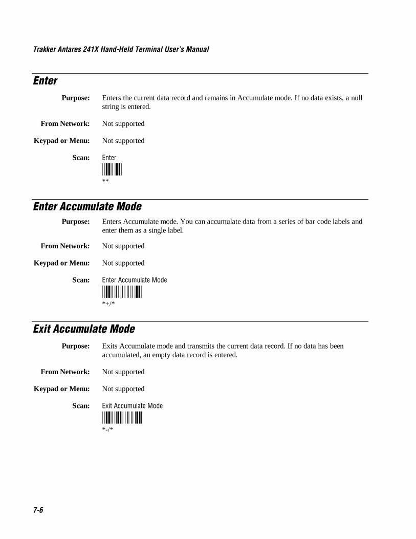
Trakker Antares 241X Hand-Held Terminal User’s Manual Nugget Co de 39
7-6
EnterPurpose: Enters the current data record and remains in Accumulate mode. If no data exists, a null
string is entered.
From Network: Not supported
Keypad or Menu: Not supported
Scan: Enter
****
Enter Accumulate ModePurpose: Enters Accumulate mode. You can accumulate data from a series of bar code labels and
enter them as a single label.
From Network: Not supported
Keypad or Menu: Not supported
Scan: Enter Accumulate Mode
*+/**+/*
Exit Accumulate ModePurpose: Exits Accumulate mode and transmits the current data record. If no data has been
accumulated, an empty data record is entered.
From Network: Not supported
Keypad or Menu: Not supported
Scan: Exit Accumulate Mode
*-/**-/*

Co de 39 Nugget Reader Command Reference
7-7
7Operating Reader Commands
This section explains the reader commands that you can use to operate or change theterminal’s configuration. The commands are:
• Backlight On and Off • Reset Firmware
• Boot Terminal • Save Configuration in Flash Memory
• Change Configuration • Scanner Trigger On and Off
• Default Configuration • Set Time and Date
• Multiple-Read Labels • Test and Service Mode
Backlight On and OffPurpose: Turns the backlight on to easily view the terminal screen in dimly lit environments.
From Network: %.1
Keypad or Menu: Press to turn the backlight on or off.
Scan: Backlight On
*%.1**%.1*
Purpose: Turns the backlight off.
From Network: %.0
Keypad or Menu: Press to turn the backlight on or off.
Scan: Backlight Off
*%.0**%.0*
Note: You can use the command %. to toggle the backlight on and off.

Trakker Antares 241X Hand-Held Terminal User’s Manual Nugget Co de 39
7-8
Boot TerminalPurpose: Boots the terminal. The terminal runs through power-on self test (POST) to test each
major subsystem. The terminal uses the configuration currently saved in flash memory toboot and then your application appears on the screen.
Use this command when you upgrade the firmware on the terminal or if your terminallocks up and will not respond.
From Network: -.1
Keypad or Menu: From the Main Menu, choose System Menu and then Upgrade Firmware. Choose OK,then YES, then press �. The Boot Menu appears. Press � to boot the terminal.
Scan: Boot Terminal
*-.1**-.1*
Change ConfigurationPurpose: This command must precede any configuration command. If you enter a valid string, the
terminal configuration is modified and the terminal sounds a high beep. For help on theconfiguration commands, see Chapter 8, “Configuration Command Reference.”
From Network: $+command[command]...[command n]
where command is a configuration command with the value you want to set.
Keypad or Menu: From the Main Menu, choose Configuration Menu.
Example: Change Configuration / Turn Off Beep Volume
*$+BV0**$+BV0*
The Change Configuration command is followed by the configuration command to turnoff the beep volume (BV0).
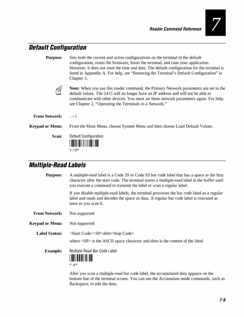
Co de 39 Nugget Reader Command Reference
7-9
7Default Configuration
Purpose: Sets both the current and active configurations on the terminal to the defaultconfiguration, resets the firmware, boots the terminal, and runs your application.However, it does not reset the time and date. The default configuration for the terminal islisted in Appendix A. For help, see “Restoring the Terminal’s Default Configuration” inChapter 3.
Note: When you use this reader command, the Primary Network parameters are set to thedefault values. The 2415 will no longer have an IP address and will not be able tocommunicate with other devices. You must set these network parameters again. For help,see Chapter 2, “Operating the Terminals in a Network.”
From Network: .+0
Keypad or Menu: From the Main Menu, choose System Menu and then choose Load Default Values.
Scan: Default Configuration
*.+0**.+0*
Multiple-Read LabelsPurpose: A multiple-read label is a Code 39 or Code 93 bar code label that has a space as the first
character after the start code. The terminal stores a multiple-read label in the buffer untilyou execute a command to transmit the label or scan a regular label.
If you disable multiple-read labels, the terminal processes the bar code label as a regularlabel and reads and decodes the space as data. A regular bar code label is executed assoon as you scan it.
From Network: Not supported
Keypad or Menu: Not supported
Label Syntax: <Start Code><SP>data<Stop Code>
where <SP> is the ASCII space character and data is the content of the label.
Example: Multiple-Read Bar Code Label
* A** A*
After you scan a multiple-read bar code label, the accumulated data appears on thebottom line of the terminal screen. You can use the Accumulate mode commands, such asBackspace, to edit the data.
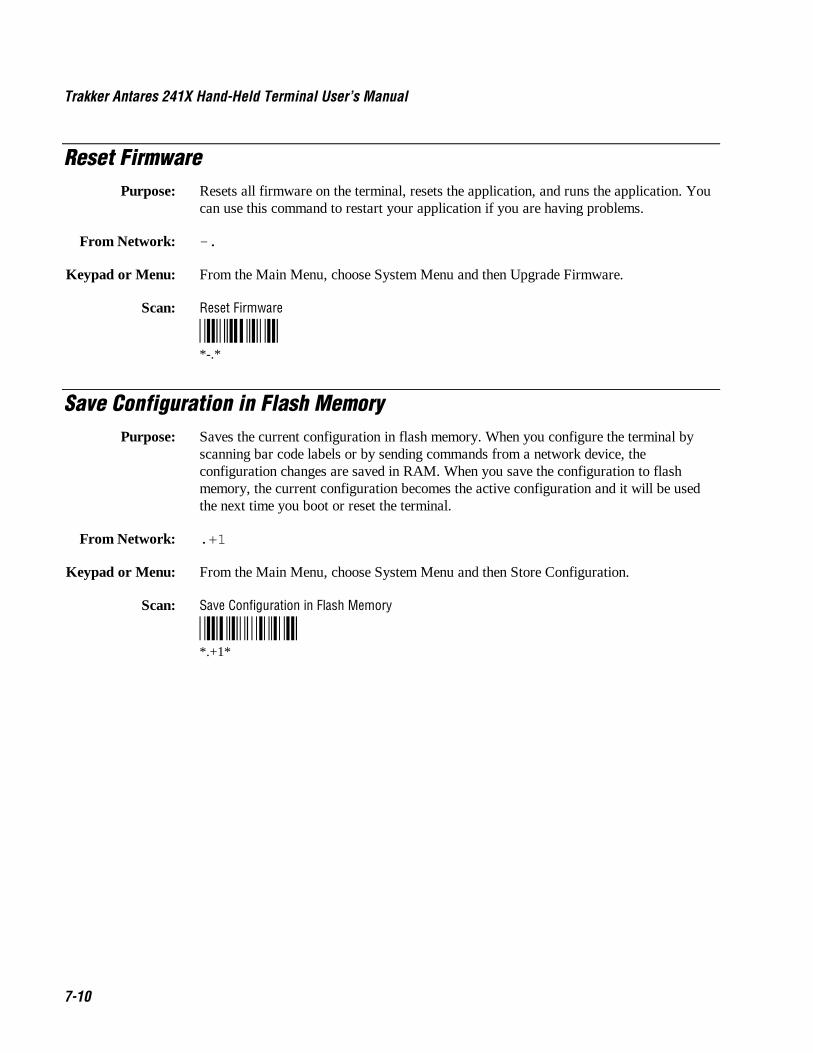
Trakker Antares 241X Hand-Held Terminal User’s Manual Nugget Co de 39
7-10
Reset FirmwarePurpose: Resets all firmware on the terminal, resets the application, and runs the application. You
can use this command to restart your application if you are having problems.
From Network: -.
Keypad or Menu: From the Main Menu, choose System Menu and then Upgrade Firmware.
Scan: Reset Firmware
*-.**-.*
Save Configuration in Flash MemoryPurpose: Saves the current configuration in flash memory. When you configure the terminal by
scanning bar code labels or by sending commands from a network device, theconfiguration changes are saved in RAM. When you save the configuration to flashmemory, the current configuration becomes the active configuration and it will be usedthe next time you boot or reset the terminal.
From Network: .+1
Keypad or Menu: From the Main Menu, choose System Menu and then Store Configuration.
Scan: Save Configuration in Flash Memory
*.+1**.+1*

Co de 39 Nugget Reader Command Reference
7-11
7Scanner Trigger On and Off
The Scanner Trigger On and the Scanner Trigger Off commands are the same as pushingand releasing the Scan button on the keypad. The Scan button and scanner triggercommands control the integrated scanner.
After a Scanner Trigger On command, the scanner operates differently depending on theScanner mode and scanner trigger configuration settings:
• If you configure the terminal to use One-Shot Scanner mode and level triggering, thescanner automatically turns off after a good read of a bar code label, or after thescanner timeout period elapses.
• If you configure the terminal to use Automatic Scanner mode and level triggering, thescanner remains on after a good read of a bar code label. You can use the ScannerTrigger Off command to turn off the scanner or you can set the Scanner Timeoutcommand to automatically turn off the scanner after it stays on for the period of timeset.
For help on configuring the Scanner Mode or Scanner Trigger commands, see Chapter 8,“Configuration Command Reference.”
Note: Intermec does not recommend that you use a Scanner Trigger On or ScannerTrigger Off command with the Scanner Trigger command set to edge triggering.
Purpose: The Scanner Trigger On command is the same as pushing the Scan button.
From Network: /.
Keypad or Menu: Press the Scan button on the keypad.
Scan: Not supported
Purpose: The Scanner Trigger Off command is the same as releasing the Scan button.
From Network: /%
Keypad or Menu: Release the Scan button on the keypad.
Scan: Not supported

Trakker Antares 241X Hand-Held Terminal User’s Manual Nugget Co de 39
7-12
Set Time and DatePurpose: Sets the time and date on the terminal. When the terminal receives the time broadcast
command from the 9154 or 9161 controller, the command sets the clock on the terminal.You can configure the clock with seconds or without seconds.
Use this command only for backward compatibility with the 95XX terminal. In the 95XXterminal documentation, this command was called Enable Clock. If you do not needbackward compatibility, use the Time and Date configuration command. For help, see“Time and Date” in Chapter 8.
From Network: /+ data
Acceptable formats for data to set the time and date are:
yy/mm/dd:hh:mm:ssyy/mm/dd:hh:mmhh:mm:sshh:mm
Year values (yy) from 00 to 95 are interpreted as 2000 through 2095. Year values from96 to 99 are interpreted as 1996 through 1999.
Keypad or Menu: Not supported.
Example: Set Time and Date to 1:30
*/+1/Z30**/+1/Z30*
Note: To use this reader command, you must configure the terminal to use Code 39 inFull ASCII mode. For help, see “Code 39” in Chapter 8.
Test and Service ModePurpose: Starts the TRAKKER Antares 2400 Menu System. From the Main Menu, the
Diagnostics Menu is the Test and Service mode you can use to run software, hardware,and system diagnostics on the terminal. For help, see Chapter 6, “Running Diagnostics.”
From Network: Not supported
Keypad or Menu: � 8 0 � ) or � 8 � � �
Scan: Test and Service Mode
*..-.**..-.*

Co de 39 Nugget Reader Command Reference
7-13
7File Management Reader Commands
This section lists the reader commands that you can use to manage files and applications.The commands are:
• Abort Program
• Delete File
• List Files
• Receive File
• Rename File
• Run Program
• Transmit File
Abort ProgramPurpose: Aborts or exits the application that is running. The terminal exits the current application
and starts running the default sample application (APPTSK.BIN).
From Network: /$
Keypad or Menu: Not supported
Scan: Abort Program
*/$**/$*

Trakker Antares 241X Hand-Held Terminal User’s Manual Nugget Co de 39
7-14
Delete FilePurpose: Deletes a file from a drive on the terminal.
From Network: ..-- drive : filename
where:
..–– is the command to delete a file.
drive indicates the drive where you want to delete a file. You must includethe colon (:) after the drive letter.
filename is the file you want to delete.
Note: You cannot use wildcard characters with this reader command. For example, youcannot send the command “..c:*.* ” to the terminal.
Keypad or Menu: From the Main Menu, choose System Menu and then choose File Manager. Choose thedrive where you want to delete files.
Scan: 1. Scan this bar code label:
Enter Accumulate Mode / Delete File
*+/..--**+/..--*
2. Scan the bar code label(s) for the file you want to delete. You can scan labels fromthe “Full ASCII Bar Code Chart” in Appendix B. The label must use this format:
drive : filename
Note: To use the bar code labels in Appendix B, you may need to configure theterminal to use Code 39 in Full ASCII mode. For help, see “Code 39” in Chapter 8.
3. Scan this bar code label to exit Accumulate mode and delete the file.
Exit Accumulate Mode
*-/**-/*
Or: You can create your own bar code labels to delete files by creating a bar code in thiscommand format:
..-- drive : filename

Co de 39 Nugget Reader Command Reference
7-15
7List Files
Purpose: A list files reader command is not available in the current release. However, if you wantto see a list of files on the terminal, you can use the TRAKKER Antares 2400 MenuSystem.
Keypad or Menu: From the Main Menu, choose System Menu and then choose File Manager. Choose thedrive where you want to list the files.
Receive FileThere are two ways to receive files on the terminals:
• Use the serial port to receive files on the terminal.
• Use RF communications to receive files on the 2415.
For help connecting the terminal to a host computer or the DCS 300, see Chapter 2,“Operating the Terminals in a Network.”
Receive File Through the Serial PortPurpose: Receives a file from the host computer through the serial port and saves it on the
terminal.
On the host, you must transmit the file using a serial communications package (i.e.,Windows 3.1 Terminal, Win95 Hyperterminal, Crosstalk, or Procomm) that supports oneof these protocols:
• XMODEM
• XMODEM-1K
• YMODEM
XMODEM-1K is a version of XMODEM that supports 1024-byte blocks and the standard128-byte XMODEM data blocks, which increases the throughput. YMODEM has theadditional ability to transfer a file name with the file’s data and it preserves the length ofthe file without padding. With YMODEM, you can also receive a batch of files on theterminal.
Note: Terminal filenames are up to eight characters with a three-character extension.Files you transfer from the host must use the Trakker Antares naming conventions.
From Network: .%Xn, drive : filename Receives a file using XMODEM protocol
.%Kn,drive : filename Receives a file using XMODEM-1K protocol
.%Yn,drive : filename Receives a file using YMODEM protocol

Trakker Antares 241X Hand-Held Terminal User’s Manual Nugget Co de 39
7-16
Receive File Through the Serial Port (continued)
Or: .%Yn, drive : Receives a batch of files using YMODEM
where:
.%X is the command to receive a file using XMODEM protocol.
.%K is the command to receive a file using XMODEM-1K protocol.
.%Y is the command to receive a file using YMODEM protocol.
n indicates the terminal’s serial port: 1.
drive indicates the drive on the terminal where you want to receive and storethe file. You must include the colon (:) after the drive letter.
filename is the file you want to receive and save on the terminal.
Keypad or Menu: Not supported
Scan: 1. Scan this bar code label:
Enter Accumulate Mode / Receive File
*+/.%**+/.%*
2. Scan the bar code label for the communications protocol you want to use.
XMODEM XMODEM-1K YMODEM
*X* *K* *Y**X* *K* *Y*
3. Scan the bar code label for the terminal COM port you are using to receive the file.The label also includes the required comma.
COM1
*1/L**1,*
4. Scan the bar code label(s) for the file you want to receive. You can scan labels fromthe “Full ASCII Bar Code Chart” in Appendix B. The label must use this format:
drive : filename
Note: To use the bar code labels in Appendix B, you may need to configure theterminal to use Code 39 in Full ASCII mode. For help, see “Code 39” in Chapter 8.
Co de 39 Nugget Reader Command Reference
7-17
7Receive File Through the Serial Port (continued)
5. Scan this bar code label to exit Accumulate mode and receive the file.
Exit Accumulate Mode
*-/**-/*
Or: You can create your own bar code labels to receive files by creating a bar code in thiscommand format:
.%Xn, drive : filename (for XMODEM)
.%Kn, drive : filename (for XMODEM-1K)
.%Yn, drive : filename (for YMODEM)
Batch Transfer: To transfer a batch of files to the terminal by using the YMODEM protocol, use yourserial communications package to start the transfer. You usually select a batch of filesusing a wild card file specification. The host must send only the filename and extension,not the drive and directory path in the data stream.
Next, use this command to receive the files on the 2410 or 2415:
.%Yn,drive :
For example, to receive the files through COM1 to drive C on the terminal, use thiscommand:
.%Y1,c:
All files that match the wild card specification are transferred from the host and receivedto drive C on the terminal. If any file does not transfer, the remainder of the batchtransfer is aborted.
Receive and Convert 7-Bit ASCII Files to 8-Bit Binary FilesPurpose: Receives a file from the host computer through the serial port, converts the file from a
7-bit ASCII hexadecimal file to an 8-bit binary file, and saves the file on the terminal.You must have the terminal connected to the host through a serial port. For help, seeChapter 2, “Operating the Terminals in a Network.”
241X applications are 8-bit binary files. Some network protocols like the Intermec Multi-Drop protocol in a CrossBar network use 7-bit ASCII files. When you send 8-bit binaryfiles across a 7-bit system without converting the files, the files are not compatible andwill not run on the terminal.

Trakker Antares 241X Hand-Held Terminal User’s Manual Nugget Co de 39
7-18
Receive and Convert 7-Bit ASCII Files to 8-Bit Binary Files (continued)
On the host, you use a hexadecimal conversion utility to convert the 8-bit binary file to a7-bit ASCII hexadecimal file. Intermec has a DOS utility called HEX.EXE to convertfiles. The source code for HEX.EXE is also available. For help, see your Intermec servicerepresentative. Once the file is converted to a 7-bit ASCII hexadecimal file, you use theReceive File command and a host utility to transfer the 7-bit file to the terminal andconvert it back to an 8-bit file.
Note: Trakker Antares filenames are up to eight characters with a three-characterextension. Files you transfer from the host need to use the Trakker Antares namingconventions.
From Network: .%Hn, drive : filename
where:
.%H is the command to receive a file that was converted from 7-bit ASCIIhexadecimal and convert it back to an 8-bit binary file. The terminaluses the current serial port configuration (protocol, baud rate, etc.) forthe file transfer.
n indicates the terminal’s serial port: 1.
drive indicates the drive on the terminal where you want to receive and storethe file. You must include the colon (:) after the drive letter.
filename is the file you want to receive and save on the terminal.
Keypad or Menu: Not supported
Scan: 1. Scan this bar code label:
Note: To scan these bar code labels, you must configure the terminal to use Code 39in Full ASCII mode. For help, see “Code 39” in Chapter 8.
Enter Accumulate Mode / Receive File
*/K/O./EH**+/.%H*
2. Scan the bar code label for the terminal COM port you are using to receive the file.The label also includes the required comma.
COM1
*1/L**1,*

Co de 39 Nugget Reader Command Reference
7-19
7Receive and Convert 7-Bit ASCII Files to 8-Bit Binary Files (continued)
3. Scan the bar code label(s) for the file you want to receive. You can scan labels fromthe “Full ASCII Bar Code Chart” in Appendix B. The label must use this format:
drive : filename
4. Scan this bar code label to exit Accumulate mode and receive the file.
Exit Accumulate Mode
*-/**-/*
Or: You can create your own bar code labels to receive files by creating a bar code in thiscommand format:
.%Hn, drive : filename
Example: You want to send an application from the host in your CrossBar network to the terminal.On the host, use HEX.EXE to convert the application from SHIPPING.BIN toSHIPPING.HEX. On the host, use a utility such as InterScan to transmit SHIPPING.HEXthrough the 9154 or 9161 to the terminal. Enter this command to receive the fileSHIPPING.BIN on the terminal’s drive C through COM2:
.%H2,c:shipping.bin
The file SHIPPING.HEX is transferred, converted from 7-bit ASCII hexadecimal to 8-bitbinary, and stored as SHIPPING.BIN on the terminal.
Receive File Via RF CommunicationsPurpose: Receives a file from the DCS 300 or host and saves it on the 2415.
From Network: .%R, fromfilename,drive : tofilename
where:
.%R is the command to receive a file that is transmitted over the RFnetwork. The “R” indicates a file transmitted via RF communicationsto the 2415.
fromfilename is the name of the file you are transmitting from the DCS 300 or host tothe 2415. On the DCS 300, the file must be sent from theD:\USERDATA directory. To receive a file from the host, you mustidentify the path and filename.
Note: Do not type D:\USERDATA in this field.
Trakker Antares 241X Hand-Held Terminal User’s Manual Nugget Co de 39
7-20
Receive File Via RF Communications (continued)
drive indicates the drive on the 2415 where you want to receive and store thefile. You must include the colon (:) after the drive letter.
tofilename is the name of the file you want to save on the 2415.
Keypad or Menu: Not supported
Scan: 1. Scan this bar code label:
Enter Accumulate Mode / Receive File
*/K/O./ER/L**+/.%R,*
2. Scan the bar code label(s) for the file you want to receive. You can scan labels fromthe “Full ASCII Bar Code Chart” in Appendix B. The label must use this format:
fromfilename,drive : tofilename
Note: To use the bar code labels in Appendix B, you may need to configure theterminal to use Code 39 in Full ASCII mode. For help, see “Code 39” in Chapter 8.
3. Scan this bar code label to exit Accumulate mode and receive the file.
Exit Accumulate Mode
*-/**-/*
Or: You can create your own bar code labels to receive files by creating a bar code in thiscommand format:
.%R, fromfilename,drive : tofilename

Co de 39 Nugget Reader Command Reference
7-21
7Rename File
Purpose: Renames a file stored on the terminal.
From Network: ...- drive:oldfilename,drive : newfilename
where:
...- is the command to rename a file.
drive indicates the drive where the oldfilename is stored. You must includethe colon (:) after the drive letter.
oldfilename is the name of the file you want to rename.
drive indicates the drive where the newfilename is stored. You must includethe colon (:) after the drive letter. The drive MUST be the same drivewhere the oldfilename is stored.
newfilename is the new name of the file.
Keypad or Menu: From the Main Menu, choose System Menu and then File Manager. Choose the drivewhere you want to rename files.
Scan: 1. Scan this bar code label:
Enter Accumulate Mode / Rename File
*+/...-**+/...-*
2. Scan the bar code label(s) for the file you want to rename. You can scan labels fromthe “Full ASCII Bar Code Chart” in Appendix B. The label must use this format:
drive:oldfilename,drive : newfilename
Note: To use the bar code labels in Appendix B, you may need to configure theterminal to use Code 39 in Full ASCII mode. For help, see “Code 39” in Chapter 8.
3. Scan this bar code label to exit Accumulate mode and rename the file.
Exit Accumulate Mode
*-/**-/*
Or: You can create your own bar code labels to rename files by creating a bar code in thiscommand format:
...- drive:oldfilename,drive : newfilename
Trakker Antares 241X Hand-Held Terminal User’s Manual Nugget Co de 39
7-22
Run ProgramPurpose: Runs the specified program or application that is stored on the terminal. For help, see
Chapter 4, “Using Custom Applications.”
Note: You cannot store and run applications from the RAM drive (E).
From Network: // drive : filename
where:
// is the command to run an application.
drive indicates the drive where the application is stored. You must include thecolon (:) after the drive letter.
filename is the application you want to run.
Keypad or Menu: From the Main Menu, choose System Menu and then File Manager. Choose the drivewhere the application is stored.
Scan: 1. Scan this bar code label:
Enter Accumulate Mode / Run Program
*+///**+///*
2. Scan the bar code label(s) for the application you want to run. You can scan labelsfrom the “Full ASCII Bar Code Chart” in Appendix B. The label must use thisformat:
drive : filename
Note: To use the bar code labels in Appendix B, you may need to configure theterminal to use Code 39 in Full ASCII mode. For help, see “Code 39” in Chapter 8.
3. Scan this bar code label to exit Accumulate mode and run the application.
Exit Accumulate Mode
*-/**-/*
Or: You can create your own bar code labels to run applications by creating a bar code inthis command format:
// drive : filename
Co de 39 Nugget Reader Command Reference
7-23
7Transmit File
There are two ways to transmit files from the terminals:
• Use the serial port to transmit files from the terminal.
• Use RF communications to transmit files from the 2415.
For help connecting the terminal to a host computer or the DCS 300, see Chapter 2,“Operating the Terminals in a Network.”
Transmit File Through the Serial PortPurpose: Transmits a file from the terminal through the serial port and saves it on the host
computer.
On the host, you must receive the file using a serial communications package (i.e.,Windows 3.1 Terminal, Win95 Hyperterminal, Crosstalk, or Procomm) that supports oneof these protocols:
• XMODEM
• XMODEM-1K
• YMODEM
XMODEM-1K is a version of XMODEM that supports 1024-byte blocks and the standard128-byte XMODEM data blocks, which increases the throughput. YMODEM has theadditional ability to transfer a file name with the file’s data and it preserves the length ofthe file without padding.
Note: Terminal filenames are up to eight characters with a three-character extension.Files you transfer from the host must use the Trakker Antares naming conventions.
From Network: %%Xn, drive : filename Transmits a file using XMODEM protocol
%%Kn,drive : filename Transmits a file using XMODEM-1K protocol
%%Yn,drive : filename Transmits a file using YMODEM protocol
where:
%%X is the command to transmit a file using XMODEM protocol.
%%K is the command to transmit a file using XMODEM-1K protocol.
%%Y is the command to transmit a file using YMODEM protocol.
n indicates the terminal’s serial port: 1.
drive indicates the drive where the file is stored on the terminal. You mustinclude the colon (:) after the drive letter.
filename is the file you want to transmit.
Keypad or Menu: Not supported

Trakker Antares 241X Hand-Held Terminal User’s Manual Nugget Co de 39
7-24
Transmit File Through the Serial Port (continued)
Scan: 1. Scan this bar code label:
Enter Accumulate Mode / Transmit File
*+/%%**+/%%*
2. Scan the bar code label for the communications protocol you want to use.
XMODEM XMODEM-1K YMODEM
*X* *K* *Y**X* *K* *Y*
3. Scan the bar code label for the terminal COM port you are using to transmit the file.The label also includes the required comma.
COM1
*1/L**1,*
4. Scan the bar code label(s) for the file you want to transmit. You can scan labels fromthe “Full ASCII Bar Code Chart” in Appendix B. The label must use this format:
drive : filename
Note: To use the bar code labels in Appendix B, you may need to configure theterminal to use Code 39 in Full ASCII mode. For help, see “Code 39” in Chapter 8.
5. Scan this bar code label to exit Accumulate mode and transmit the file.
Exit Accumulate Mode
*-/**-/*
Or: You can create your own bar code labels to transmit files by creating a bar code in thiscommand format:
%%Xn, drive : filename (for XMODEM)
%%Kn,drive : filename (for XMODEM-1K)
%%Yn,drive : filename (for YMODEM)

Co de 39 Nugget Reader Command Reference
7-25
7Transmit and Convert 8-Bit Binary Files to 7-Bit ASCII Files
Purpose: Converts the file from an 8-bit binary file to a 7-bit ASCII hexadecimal file, transmits thefile from the terminal through the serial port, and saves the file on the host computer. Youmust have the terminal connected to the host through a serial port. For help, see Chapter2, “Operating the Terminals in a Network.”
241X applications are 8-bit binary files. Some network protocols like the Intermec Multi-Drop protocol in a CrossBar network use 7-bit ASCII files. When you send 8-bit binaryfiles across a 7-bit system without converting the files, the files are not compatible andwill not run.
You use the Transmit File command and a host utility to convert the 8-bit binary file to a7-bit ASCII hexadecimal file and transfer it from the terminal. On the host, you use ahexadecimal conversion utility to convert the 7-bit ASCII hexadecimal file to an 8-bitbinary file. Intermec has a DOS utility called HEX.EXE to convert files. The source codefor HEX.EXE is also available. For help, see your Intermec service representative.
Note: Trakker Antares filenames are up to eight characters with a three-characterextension.
From Network: %%Hn, drive : filename
where:
%%H is the command to convert an 8-bit binary file to a 7-bit ASCIIhexadecimal file and transmit it. The terminal uses the current serialport configuration (protocol, baud rate, etc.) for the file transfer.
n indicates the terminal’s serial port: 1.
drive indicates the drive where the file is stored on the terminal. You mustinclude the colon (:) after the drive letter.
filename is the file you want to transmit.
Keypad or Menu: Not supported

Trakker Antares 241X Hand-Held Terminal User’s Manual Nugget Co de 39
7-26
Transmit and Convert 8-Bit Binary Files to 7-Bit ASCII Files (continued)
Scan: 1. Scan this bar code label:
Note: To scan these bar code labels, you must configure the terminal to use Code 39in Full ASCII mode. For help, see “Code 39” in Chapter 8.
Enter Accumulate Mode / Transmit File
*/K/O/E/EH**+/%%H*
2. Scan the bar code label for the terminal COM port you are using to transmit the file.The label also includes the required comma.
COM1
*1/L**1,*
3. Scan the bar code label(s) for the file you want to transmit. You can scan labels fromthe “Full ASCII Bar Code Chart” in Appendix B. The label must use this format:
drive : filename
4. Scan this bar code label to exit Accumulate mode and transmit the file.
Exit Accumulate Mode
*-/**-/*
Or: You can create your own bar code labels to transmit files by creating a bar code in thiscommand format:
%%Hn, drive : filename
Example: You want to upload an application from the terminal in your CrossBar network to thehost. On the host, you need to receive the file using a utility such as InterScan. Enter thiscommand to transmit the file SHIPPING.BIN from the terminal’s drive C through COM2:
%%H2,c:shipping.bin
The file is converted from 8-bit binary to 7-bit ASCII hexadecimal and transmitted to thehost. Use HEX.EXE to convert the application back to its original 8-bit binary format.
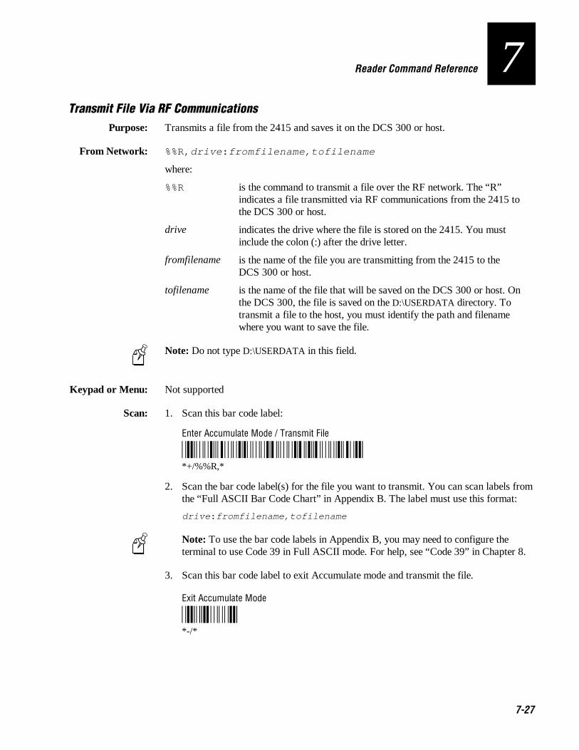
Co de 39 Nugget Reader Command Reference
7-27
7Transmit File Via RF Communications
Purpose: Transmits a file from the 2415 and saves it on the DCS 300 or host.
From Network: %%R,drive : fromfilename,tofilename
where:
%%R is the command to transmit a file over the RF network. The “R”indicates a file transmitted via RF communications from the 2415 tothe DCS 300 or host.
drive indicates the drive where the file is stored on the 2415. You mustinclude the colon (:) after the drive letter.
fromfilename is the name of the file you are transmitting from the 2415 to theDCS 300 or host.
tofilename is the name of the file that will be saved on the DCS 300 or host. Onthe DCS 300, the file is saved on the D:\USERDATA directory. Totransmit a file to the host, you must identify the path and filenamewhere you want to save the file.
Note: Do not type D:\USERDATA in this field.
Keypad or Menu: Not supported
Scan: 1. Scan this bar code label:
Enter Accumulate Mode / Transmit File
*/K/O/E/ER/L**+/%%R,*
2. Scan the bar code label(s) for the file you want to transmit. You can scan labels fromthe “Full ASCII Bar Code Chart” in Appendix B. The label must use this format:
drive : fromfilename,tofilename
Note: To use the bar code labels in Appendix B, you may need to configure theterminal to use Code 39 in Full ASCII mode. For help, see “Code 39” in Chapter 8.
3. Scan this bar code label to exit Accumulate mode and transmit the file.
Exit Accumulate Mode
*-/**-/*

Trakker Antares 241X Hand-Held Terminal User’s Manual Nugget Co de 39
7-28
Transmit File Via RF Communications (continued)
Or: You can create your own bar code labels to transmit files by creating a bar code in thiscommand format:
%%R,drive : fromfilename,tofilename

Configuration Command Reference
8

9-2

Co de 39 Nugget Configuration Command Reference
8-3
8This chapter is an alphabetical list of all the configuration commands supported onthe terminal.
Using Configuration CommandsA configuration command changes the way the Trakker Antares 2410 and 2415 terminalsoperate. For example, you can change the Beep Volume command and make the terminalbeep very loudly in a noisy environment. You can execute configuration commands by
• scanning a command from a Code 39 or Code 93 bar code label. These labels areprovided in this chapter. For more help, see Chapter 3, “Configuring the Terminal.”
• choosing a command from the TRAKKER Antares 2400 Menu System. For helpusing the menu system, see Chapter 3, “Configuring the Terminal.”
• sending a command from a device on the serial or RF network. For help, see “UsingSerial Communications on the Terminals” and “Connecting the 2415 to an RFNetwork” in Chapter 2.
You can find this information about each configuration command in this chapter:
• Command description and purpose
• Command syntax and options
• Default setting
• Location within the TRAKKER Antares 2400 Menu System
• Bar code labels you can scan to set or change each command
The configuration commands are listed alphabetically by command name. For a list ofbar code symbology, operations, serial network communications, or RF networkcommunications commands, use the next table, “Configuration Commands Listed byCategory.” If you want to look up a command by its syntax, see the “ConfigurationCommands by Syntax” list in Appendix A.
Note: The Code 39 bar code labels in this chapter show an asterisk (*) at the beginningand end of the human-readable interpretation to represent the start and stop codes. If youare creating your own Code 39 bar code labels, your bar code printing utility mayautomatically supply the asterisks as the start/stop code.

Trakker Antares 241X Hand-Held Terminal User’s Manual Co de 39 Nugget
8-4
Configuration Commands Listed by CategoryThis chapter lists the configuration commands in alphabetical order. Use this next list tofind the configuration commands you may need to set for bar code symbologies,operations, serial network communications, or RF network communications.
Operations Bar Code Symbologies
Append Time, 8-12 Codabar, 8-19
Automatic Shutoff, 8-13 Code 11, 8-21
Beep Volume, 8-17 Code 16K, 8-22
Command Processing, 8-39 Code 2 of 5, 8-23
Decode Security, 8-52 Code 39, 8-25
Display Backlight Timeout, 8-55 Code 49, 8-29
Display Contrast, 8-57 Code 93, 8-31
Display Font Type, 8-58 Code 128, 8-32
Display Row Spacing, 8-59 Interleaved 2 of 5, 8-75
Display Video Mode, 8-60 MSI, 8-86
Flash Memory Configuration, 8-66 Plessey, 8-95
Keypad Caps Lock, 8-77 UPC/EAN, 8-140
Keypad Clicker, 8-78
Keypad Type, 8-79
Postamble, 8-97
Preamble, 8-100
RAM Drive Size, 8-102
Resume Execution, 8-108
Scan Ahead, 8-110
Scanner Mode, 8-111
Scanner Redundancy, 8-112
Scanner Selection, 8-113
Scanner Timeout, 8-114
Scanner Trigger, 8-116
Suspend/Resume Control, 8-126
Time and Date, 8-133
Time in Seconds, 8-135

Co de 39 Nugget Configuration Command Reference
8-5
8Configuration Commands Listed by Category (continued)
RF Network Communications Serial Network Communications
Acknowledgement Delay Lower Limit, 8-7 Baud Rate, 8-15
Acknowledgement Delay Upper Limit, 8-9 Configuration Commands Via Serial Port, 8-43
AP Density, 8-11 Data Bits, 8-51
Controller Connect Check Receive Timer, 8-45 End of Message (EOM), 8-64
Controller Connect Check Send Timer, 8-47 Flow Control, 8-68
Controller IP Address, 8-49 Handshake, 8-70
Default Router, 8-53 LRC (Longitudinal Redundancy Check), 8-81
Domain, 8-61 Parity, 8-94
Dynamic Host Configuration Protocol (DHCP), 8-63 Poll (Polling), 8-96
Host IP Address, 8-71 Serial Port Protocol, 8-118
Inactivity Timeout, 8-73 Start of Message (SOM), 8-120
Maximum Retries, 8-82 Stop Bits, 8-123
Maximum Sleep Duration, 8-84 Timeout Delay, 8-136
Network Activate, 8-88
Network Loopback, 8-89
Network Name, 8-90
Network Port, 8-92
Power Management, 8-99
Receive All Multicast, 8-104
Reservation, 8-105
Reservation Enable, 8-107
Roaming Flag, 8-109
Security Identification (ID), 8-117
Station Name, 8-122
Subnet Mask, 8-124
TCP/IP Maximum Retries, 8-127
TCP/IP Maximum Transmit Timeout, 8-129
Terminal IP Address, 8-131
Transmit Mode, 8-138
Transmit Rate, 8-139
Wakeup On Broadcast, 8-143

Trakker Antares 241X Hand-Held Terminal User’s Manual Co de 39 Nugget
8-6
Entering Variable Data in a Configuration CommandYou can enter variable data for many of the configuration commands. For example, youcan set a preamble that is up to 25 ASCII characters long. You need to follow thesegeneral instructions to enter variable data.
To enter variable data in a configuration command
1. Scan a bar code label with this syntax:
+/$+ command
where:
+/ is the syntax for the Enter Accumulate Mode command.
$+ is the syntax for the Change Configuration command.
command is the syntax for the command you want to change.
For example, the command syntax for a preamble is ADdata. To change or set apreamble, scan this bar code:
Enter Accumulate Mode / Change Configuration / Set Preamble
*+/$+AD**+/$+AD*
2. Scan a bar code label from the “Full ASCII Bar Code Chart” in Appendix B. To setthe preamble to the character T, scan this label:
T
*T**T*
Note: To use the bar code labels in Appendix B, you may need to configure theterminal to use Code 39 in Full ASCII mode. For help, see “Code 39” later in thischapter.
3. Scan the Exit Accumulate Mode bar code label to update the terminal’sconfiguration:
Exit Accumulate Mode
*-/**-/*
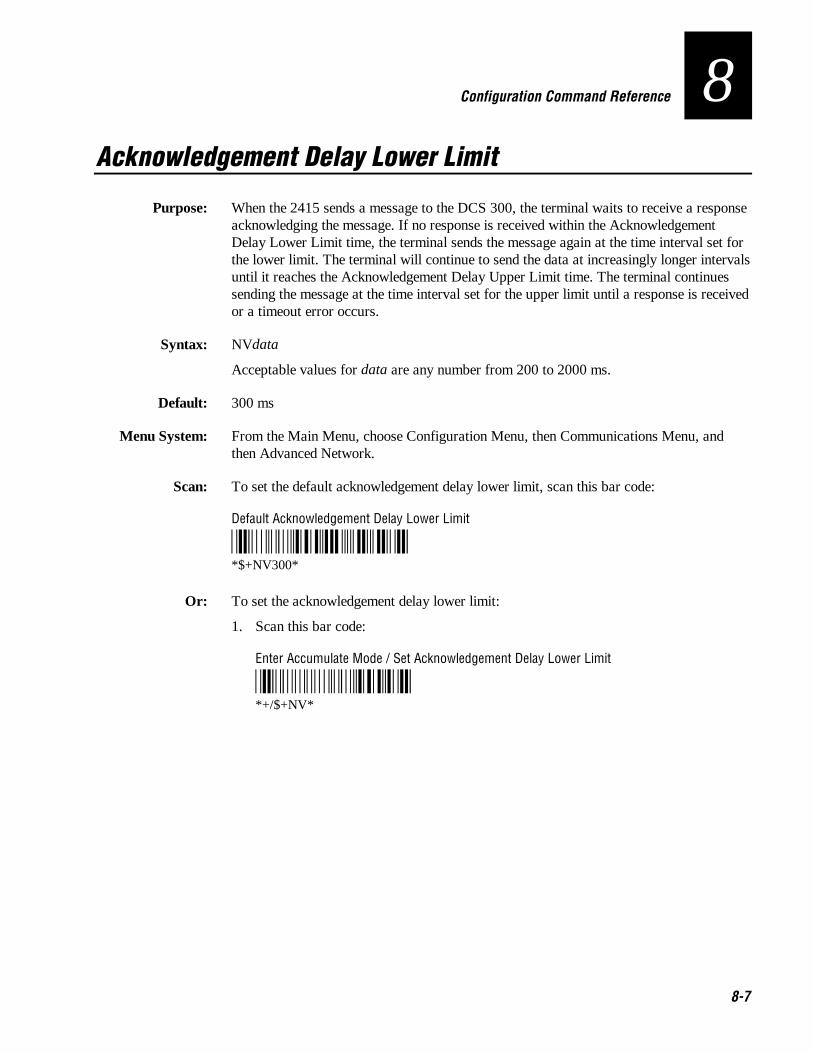
Co de 39 Nugget Configuration Command Reference
8-7
8Acknowledgement Delay Lower Limit
Purpose: When the 2415 sends a message to the DCS 300, the terminal waits to receive a responseacknowledging the message. If no response is received within the AcknowledgementDelay Lower Limit time, the terminal sends the message again at the time interval set forthe lower limit. The terminal will continue to send the data at increasingly longer intervalsuntil it reaches the Acknowledgement Delay Upper Limit time. The terminal continuessending the message at the time interval set for the upper limit until a response is receivedor a timeout error occurs.
Syntax: NVdata
Acceptable values for data are any number from 200 to 2000 ms.
Default: 300 ms
Menu System: From the Main Menu, choose Configuration Menu, then Communications Menu, andthen Advanced Network.
Scan: To set the default acknowledgement delay lower limit, scan this bar code:
Default Acknowledgement Delay Lower Limit
*$+NV300**$+NV300*
Or: To set the acknowledgement delay lower limit:
1. Scan this bar code:
Enter Accumulate Mode / Set Acknowledgement Delay Lower Limit
*+/$+NV**+/$+NV*
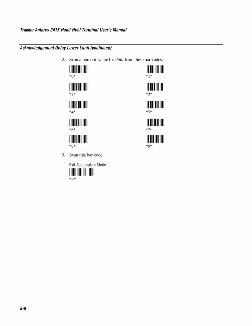
Trakker Antares 241X Hand-Held Terminal User’s Manual Co de 39 Nugget
8-8
Acknowledgement Delay Lower Limit (continued)
2. Scan a numeric value for data from these bar codes:
*0* *1**0* *1*
*2* *3**2* *3*
*4* *5**4* *5*
*6* *7**6* *7*
*8* *9**8* *9*
3. Scan this bar code:
Exit Accumulate Mode
*-/**-/*

Co de 39 Nugget Configuration Command Reference
8-9
8Acknowledgement Delay Upper Limit
Purpose: When the 2415 sends a message to the DCS 300, the terminal waits to receive a responseacknowledging the message. If no response is received within the AcknowledgementDelay Lower Limit time, the terminal sends the message again at the time interval set forthe lower limit. The terminal will continue to send the data at increasingly longer intervalsuntil it reaches the Acknowledgement Delay Upper Limit time. The terminal continuessending the message at the time interval set for the upper limit until a response is receivedor a timeout error occurs.
Syntax: NUdata
Acceptable values for data are any number from 2000 to 60000 ms.
Default: 5000 ms
Menu System: From the Main Menu, choose Configuration Menu, then Communications Menu, andthen Advanced Network.
Scan: To set the default acknowledgement delay upper limit, scan this bar code:
Default Acknowledgement Delay Upper Limit
*$+NU5000**$+NU5000*
Or: To set the acknowledgement delay upper limit:
1. Scan this bar code:
Enter Accumulate Mode / Set Acknowledgement Delay Upper Limit
*+/$+NU**+/$+NU*

Trakker Antares 241X Hand-Held Terminal User’s Manual Co de 39 Nugget
8-10
Acknowledgement Delay Upper Limit (continued)
2. Scan a numeric value for data from these bar codes:
*0* *1**0* *1*
*2* *3**2* *3*
*4* *5**4* *5*
*6* *7**6* *7*
*8* *9**8* *9*
3. Scan this bar code:
Exit Accumulate Mode
*-/**-/*

Co de 39 Nugget Configuration Command Reference
8-11
8AP Density
Purpose: (IEEE 802.11 DS radio parameter) Controls the roaming sensitivity of the radios. Youcan use this parameter to virtually reduce the range of the radio. When you increase theAP density, you do not reduce the absolute range of the radio, but the roaming algorithmsare modified to allow significant overlap of the radio coverage. Increasing the AP densitylets you create a higher performance radio network, but you will need significantly moreaccess points to cover a given area.
Syntax: LFdata
Acceptable values for data are:
0 Low density1 Medium density2 High density
Default: Low density
Menu System: From the Main Menu, choose Configuration Menu, then Communications Menu, andthen Radio.
Scan: One of these bar codes:
Low AP Density
*$+LF0**$+LF0*
Medium AP Density
*$+LF1**$+LF1*
High AP Density
*$+LF2**$+LF2*

Trakker Antares 241X Hand-Held Terminal User’s Manual Co de 39 Nugget
8-12
Append Time
Purpose: Appends the time to bar code labels that are scanned on the terminal. You can also usethe Time in Seconds command to append the time in hours and minutes only, or hours,minutes, and seconds. The time is appended to the data in the form HH:MM:SS. Forhelp, see “Time in Seconds” later in this chapter.
Syntax: DEdata
Acceptable values for data are:
0 Disabled1 Enabled
Default: Disabled
Menu System: From the Main Menu, choose Configuration Menu, then Terminal Menu, and thenAppend Time.
Scan: One of these bar codes:
Disable Append Time
*$+DE0**$+DE0*
Enable Append Time
*$+DE1**$+DE1*

Co de 39 Nugget Configuration Command Reference
8-13
8Automatic Shutoff
Purpose: Defines the maximum length of time the terminal remains on when there is no activity.When you do not use the terminal for the length of time set with this command, theterminal automatically turns off as if you had pressed : to turn it off.
When you press : to turn on the terminal, the terminal either resumes exactly where itwas when you turned it off or the terminal boots and restarts your application. Resume iscontrolled through the Resume Execution command. For help, see “Resume Execution”later in this chapter.
Power Management Tip: You should use the Automatic Shutoff feature to preservebattery pack power.
Syntax: EZdata
Acceptable values for data are:
0 Disabled (always on)02-75 Shutoff time in minutes
Default: Disabled
Menu System: From the Main Menu, choose Configuration Menu, then Terminal Menu, and then PowerManagement.
Scan: To disable automatic shutoff, scan this bar code:
Disable Automatic Shutoff
*$+EZ0**$+EZ0*
Or: To set a timeout:
1. Scan this bar code:
Enter Accumulate Mode / Set Automatic Shutoff
*+/$+EZ**+/$+EZ*
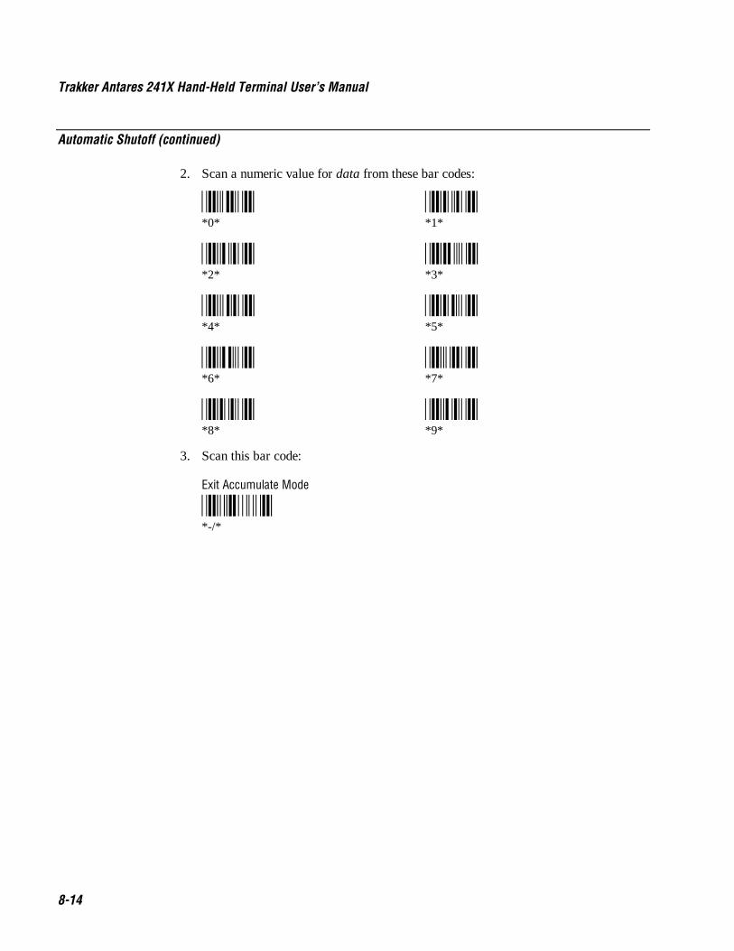
Trakker Antares 241X Hand-Held Terminal User’s Manual Co de 39 Nugget
8-14
Automatic Shutoff (continued)
2. Scan a numeric value for data from these bar codes:
*0* *1**0* *1*
*2* *3**2* *3*
*4* *5**4* *5*
*6* *7**6* *7*
*8* *9**8* *9*
3. Scan this bar code:
Exit Accumulate Mode
*-/**-/*
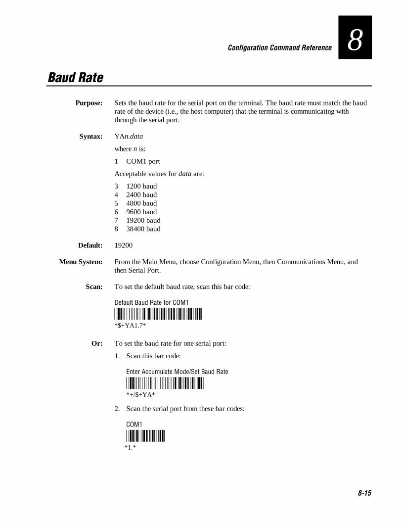
Co de 39 Nugget Configuration Command Reference
8-15
8Baud Rate
Purpose: Sets the baud rate for the serial port on the terminal. The baud rate must match the baudrate of the device (i.e., the host computer) that the terminal is communicating withthrough the serial port.
Syntax: YAn.data
where n is:
1 COM1 port
Acceptable values for data are:
3 1200 baud4 2400 baud5 4800 baud6 9600 baud7 19200 baud8 38400 baud
Default: 19200
Menu System: From the Main Menu, choose Configuration Menu, then Communications Menu, andthen Serial Port.
Scan: To set the default baud rate, scan this bar code:
Default Baud Rate for COM1
*$+YA1.7**$+YA1.7*
Or: To set the baud rate for one serial port:
1. Scan this bar code:
Enter Accumulate Mode/Set Baud Rate
*+/$+YA**+/$+YA*
2. Scan the serial port from these bar codes:
COM1
*1.**1.*
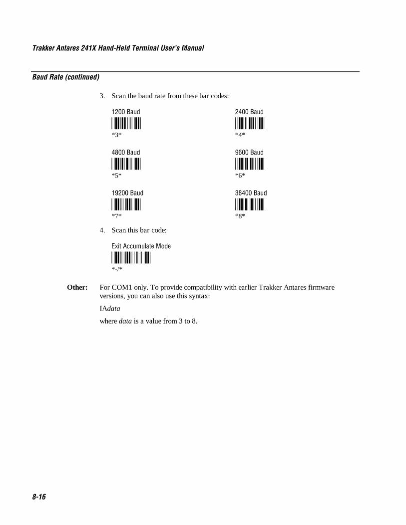
Trakker Antares 241X Hand-Held Terminal User’s Manual Co de 39 Nugget
8-16
Baud Rate (continued)
3. Scan the baud rate from these bar codes:
1200 Baud 2400 Baud
*3* *4**3* *4*
4800 Baud 9600 Baud
*5* *6**5* *6*
19200 Baud 38400 Baud
*7* *8**7* *8*
4. Scan this bar code:
Exit Accumulate Mode
*-/**-/*
Other: For COM1 only. To provide compatibility with earlier Trakker Antares firmwareversions, you can also use this syntax:
IAdata
where data is a value from 3 to 8.
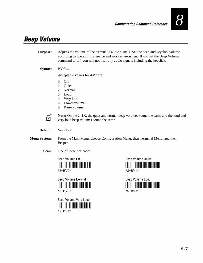
Co de 39 Nugget Configuration Command Reference
8-17
8Beep Volume
Purpose: Adjusts the volume of the terminal’s audio signals. Set the beep and keyclick volumeaccording to operator preference and work environment. If you set the Beep Volumecommand to off, you will not hear any audio signals including the keyclick.
Syntax: BVdata
Acceptable values for data are:
0 Off1 Quiet2 Normal3 Loud4 Very loud8 Lower volume9 Raise volume
Note: On the 241X, the quiet and normal beep volumes sound the same and the loud andvery loud beep volumes sound the same.
Default: Very loud
Menu System: From the Main Menu, choose Configuration Menu, then Terminal Menu, and thenBeeper.
Scan: One of these bar codes:
Beep Volume Off Beep Volume Quiet
*$+BV0* *$+BV1**$+BV0* *$+BV1*
Beep Volume Normal Beep Volume Loud
*$+BV2* *$+BV3**$+BV2* *$+BV3*
Beep Volume Very Loud
*$+BV4**$+BV4*

Trakker Antares 241X Hand-Held Terminal User’s Manual Co de 39 Nugget
8-18
Beep Volume (continued)
Or: Scan one of these bar codes repeatedly to achieve the desired volume:
Raise Beep Volume
*$+BV9**$+BV9*
Lower Beep Volume
*$+BV8**$+BV8*

Co de 39 Nugget Configuration Command Reference
8-19
8Codabar
Purpose: Enables or disables decoding of Codabar symbology. Codabar is a self-checking, discretesymbology. The American Blood Commission (ABC) Codabar requires that you retain andtransmit the start/stop code digits when processing a Codabar symbol. As a result,configuration CD10 is an illegal configuration.
Syntax: CDdata
Acceptable values for data must be two digits, corresponding to:
Digit Value Description
First 0 Disabled1 ABC2 Standard3 Concatenated
Second 0 Discard Start/Stop1 Transmit ABCD Start/Stop2 Transmit DC1-DC4 Start/Stop
Default: Disabled
Menu System: From the Main Menu, choose Configuration Menu, then Symbologies Menu, and thenCodabar.
Scan: One of these bar codes:
Disabled, Discard Start/Stop
*$+CD00**$+CD00*
ABC, Transmit ABCD Start/Stop
*$+CD11**$+CD11*
ABC, Transmit DC1-DC4 Start/Stop
*$+CD12**$+CD12*

Trakker Antares 241X Hand-Held Terminal User’s Manual Co de 39 Nugget
8-20
Codabar (continued)
Standard, Discard Start/Stop
*$+CD20**$+CD20*
Standard, Transmit ABCD Start/Stop
*$+CD21**$+CD21*
Standard, Transmit DC1-DC4 Start/Stop
*$+CD22**$+CD22*
Concatenated, Discard Start/Stop
*$+CD30**$+CD30*
Concatenated, Transmit ABCD Start/Stop
*$+CD31**$+CD31*
Concatenated, Transmit DC1-DC4 Start/Stop
*$+CD32**$+CD32*

Co de 39 Nugget Configuration Command Reference
8-21
8Code 11
Purpose: Enables or disables decoding of Code 11 symbology. Code 11 is a very high density,discrete numeric bar code. It is most extensively used in labeling telecommunicationscomponents and equipment.
Syntax: CGdata
Acceptable values for data are:
0 Disabled1 Code 11 enabled with one check digit2 Code 11 enabled with two check digits
Default: Disabled
Menu System: From the Main Menu, choose Configuration Menu, then Symbologies Menu, and thenCode 11.
Scan: One of these bar codes:
Disable Code 11
*$+CG0**$+CG0*
Code 11 Enabled With One Check Digit
*$+CG1**$+CG1*
Code 11 Enabled With Two Check Digits
*$+CG2**$+CG2*

Trakker Antares 241X Hand-Held Terminal User’s Manual Co de 39 Nugget
8-22
Code 16K
Purpose: Enables or disables decoding of Code 16K symbology. Code 16K is a two-dimensional(stacked rows), high density bar code. It is based on Code 128 and is used widely to labelunit-dose packaging for the healthcare industry.
Syntax: CPdata
Acceptable values for data are:
0 Disabled1 Standard Code 16K enabled2 Code 16K enabled with Function Code 1
When you enable Code 16K with Function Code 1, the terminal decodes the bar codelabel and checks for a Function Code 1 in the first data character position. If a FunctionCode 1 is the first character, the terminal substitutes this Code 16K symbology identifierstring for the Function Code 1 character.
]K1
Default: Disabled
Menu System: From the Main Menu, choose Configuration Menu, then Symbologies Menu, and thenCode 16K.
Scan: One of these bar codes:
Disable Code 16K
*$+CP0**$+CP0*
Standard Code 16K Enabled
*$+CP1**$+CP1*
Code 16K Enabled With Function Code 1
*$+CP2**$+CP2*
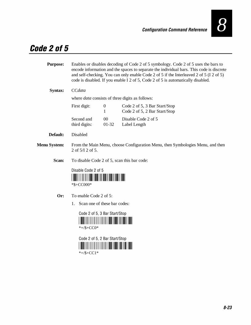
Co de 39 Nugget Configuration Command Reference
8-23
8Code 2 of 5
Purpose: Enables or disables decoding of Code 2 of 5 symbology. Code 2 of 5 uses the bars toencode information and the spaces to separate the individual bars. This code is discreteand self-checking. You can only enable Code 2 of 5 if the Interleaved 2 of 5 (I 2 of 5)code is disabled. If you enable I 2 of 5, Code 2 of 5 is automatically disabled.
Syntax: CCdata
where data consists of three digits as follows:
First digit: 0 Code 2 of 5, 3 Bar Start/Stop1 Code 2 of 5, 2 Bar Start/Stop
Second and 00 Disable Code 2 of 5third digits: 01-32 Label Length
Default: Disabled
Menu System: From the Main Menu, choose Configuration Menu, then Symbologies Menu, and then2 of 5/I 2 of 5.
Scan: To disable Code 2 of 5, scan this bar code:
Disable Code 2 of 5
*$+CC000**$+CC000*
Or: To enable Code 2 of 5:
1. Scan one of these bar codes:
Code 2 of 5, 3 Bar Start/Stop
*+/$+CC0**+/$+CC0*
Code 2 of 5, 2 Bar Start/Stop
*+/$+CC1**+/$+CC1*

Trakker Antares 241X Hand-Held Terminal User’s Manual Co de 39 Nugget
8-24
Code 2 of 5 (continued)
2. Scan a two-digit numeric value to set the label length (01-32) from these bar codes.
*0* *1**0* *1*
*2* *3**2* *3*
*4* *5**4* *5*
*6* *7**6* *7*
*8* *9**8* *9*
3. Scan this bar code:
Exit Accumulate Mode
*-/**-/*

Co de 39 Nugget Configuration Command Reference
8-25
8Code 39
Purpose: Enables or disables decoding of Code 39 symbology. Code 39 is discrete, variable length,and self-checking. The character set is uppercase A to Z, 0 to 9, dollar sign ($),period (.), slash (/), percent (%), space ( ), plus (+), and minus (-).
There are three types of ASCII the terminal decodes:
• Code 39 non-full ASCII
• Code 39 full ASCII
• Code 39 mixed-full ASCII
Code 39 non-full ASCII Non-full ASCII uses a one-character encoding scheme. Forexample, you encode the data “SAMPLE” as follows:
*SAMPLE**SAMPLE*
This label decodes as SAMPLE.
Code 39 full ASCII Full ASCII uses a two-character encoding scheme to extend thecharacter set to 128 characters. You use the dollar sign ($), slash (/), percent (%), or plus(+) followed by an uppercase letter to represent one of the characters in the extended set.You must encode lowercase letters as a plus sign (+) followed by their uppercaseequivalents. For a list of ASCII characters and their Code 39 representations, see the“Full ASCII Table” in Appendix B.
Use Code 39 full ASCII to enter ASCII control characters or lowercase characters asdata. You should also enable Code 39 full ASCII to use ASCII command characters.
For example, you encode the data “sample” in Code 39 full ASCII as follows:
*+S+A+M+P+L+E**+S+A+M+P+L+E*
In Code 39 non-full ASCII, this label decodes as +S+A+M+P+L+E . In Code 39 fullASCII, this label decodes as sample.
Code 39 mixed-full ASCII Use mixed-full ASCII when printers encode the same labeltwo different ways. For example, if you have a bar code with the data $%a, some printersencode the data as follows:
*/D/E+A**/D/E+A*
In the Full ASCII Table in Appendix B, /D represents $ and /E represents %. If youconfigure the terminal for Code 39 full ASCII, the terminal decodes the data as $%abecause there are three valid full ASCII character pairs to represent the data.
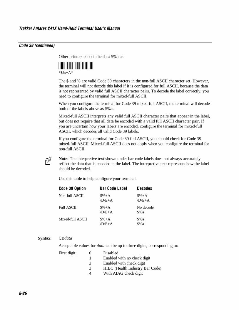
Trakker Antares 241X Hand-Held Terminal User’s Manual Co de 39 Nugget
8-26
Code 39 (continued)
Other printers encode the data $%a as:
*$%+A**$%+A*
The $ and % are valid Code 39 characters in the non-full ASCII character set. However,the terminal will not decode this label if it is configured for full ASCII, because the datais not represented by valid full ASCII character pairs. To decode the label correctly, youneed to configure the terminal for mixed-full ASCII.
When you configure the terminal for Code 39 mixed-full ASCII, the terminal will decodeboth of the labels above as $%a.
Mixed-full ASCII interprets any valid full ASCII character pairs that appear in the label,but does not require that all data be encoded with a valid full ASCII character pair. Ifyou are uncertain how your labels are encoded, configure the terminal for mixed-fullASCII, which decodes all valid Code 39 labels.
If you configure the terminal for Code 39 full ASCII, you should check for Code 39mixed-full ASCII. Mixed-full ASCII does not apply when you configure the terminal fornon-full ASCII.
Note: The interpretive text shown under bar code labels does not always accuratelyreflect the data that is encoded in the label. The interpretive text represents how the labelshould be decoded.
Use this table to help configure your terminal.
Code 39 Option Bar Code Label Decodes
Non-full ASCII $%+A/D/E+A
$%+A/D/E+A
Full ASCII $%+A/D/E+A
No decode$%a
Mixed-full ASCII $%+A/D/E+A
$%a$%a
Syntax: CBdata
Acceptable values for data can be up to three digits, corresponding to:
First digit: 0 Disabled1 Enabled with no check digit2 Enabled with check digit3 HIBC (Health Industry Bar Code)4 With AIAG check digit

Co de 39 Nugget Configuration Command Reference
8-27
8Code 39 (continued)
Second digit: 0 Discard check digit1 Transmit check digit
Third digit: 0 Code 39 non-full ASCII1 Code 39 full ASCII2 Code 39 mixed-full ASCII
Note: Selecting HIBC Code 39 automatically sets the configuration to non-full ASCIIwith the check digit transmitted.
Default: Enable Code 39 Full ASCII with no check digit (111)
Menu System: From the Main Menu, choose Configuration Menu, then Symbologies Menu, and thenCode 39.
Scan: To disable Code 39, scan this bar code:
Disable Code 39
*$+CB0**$+CB0*
Or: To enable Code 39:
1. Scan this bar code:
Enter Accumulate Mode / Enable Code 39
*+/$+CB**+/$+CB*
2. Scan one of these bar codes to set the first digit:
Without a Check Digit With a Check Digit
*1* *2**1* *2*
HIBC Code 39 With AIAG Check Digit
*3* *4**3* *4*

Trakker Antares 241X Hand-Held Terminal User’s Manual Co de 39 Nugget
8-28
Code 39 (continued)
3. Scan one of these bar codes to set the second digit:
Discard Check Digit Transmit Check Digit
*0* *1**0* *1*
4. Scan one of these bar codes to set the third digit:
Code 39 Non-Full ASCII Code 39 Full ASCII
*0* *1**0* *1*
Code 39 Mixed-Full ASCII
*2**2*
5. Scan this bar code:
Exit Accumulate Mode
*-/**-/*
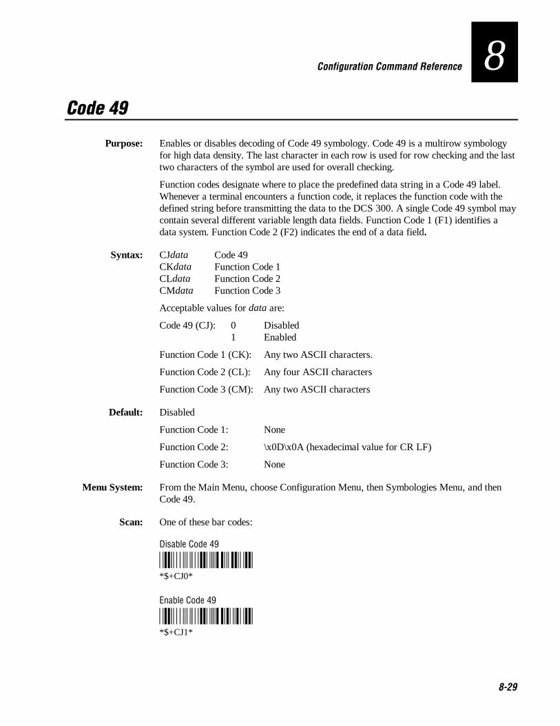
Co de 39 Nugget Configuration Command Reference
8-29
8Code 49
Purpose: Enables or disables decoding of Code 49 symbology. Code 49 is a multirow symbologyfor high data density. The last character in each row is used for row checking and the lasttwo characters of the symbol are used for overall checking.
Function codes designate where to place the predefined data string in a Code 49 label.Whenever a terminal encounters a function code, it replaces the function code with thedefined string before transmitting the data to the DCS 300. A single Code 49 symbol maycontain several different variable length data fields. Function Code 1 (F1) identifies adata system. Function Code 2 (F2) indicates the end of a data field.
Syntax: CJdata Code 49CKdata Function Code 1CLdata Function Code 2CMdata Function Code 3
Acceptable values for data are:
Code 49 (CJ): 0 Disabled1 Enabled
Function Code 1 (CK): Any two ASCII characters.
Function Code 2 (CL): Any four ASCII characters
Function Code 3 (CM): Any two ASCII characters
Default: Disabled
Function Code 1: None
Function Code 2: \x0D\x0A (hexadecimal value for CR LF)
Function Code 3: None
Menu System: From the Main Menu, choose Configuration Menu, then Symbologies Menu, and thenCode 49.
Scan: One of these bar codes:
Disable Code 49
*$+CJ0**$+CJ0*
Enable Code 49
*$+CJ1**$+CJ1*
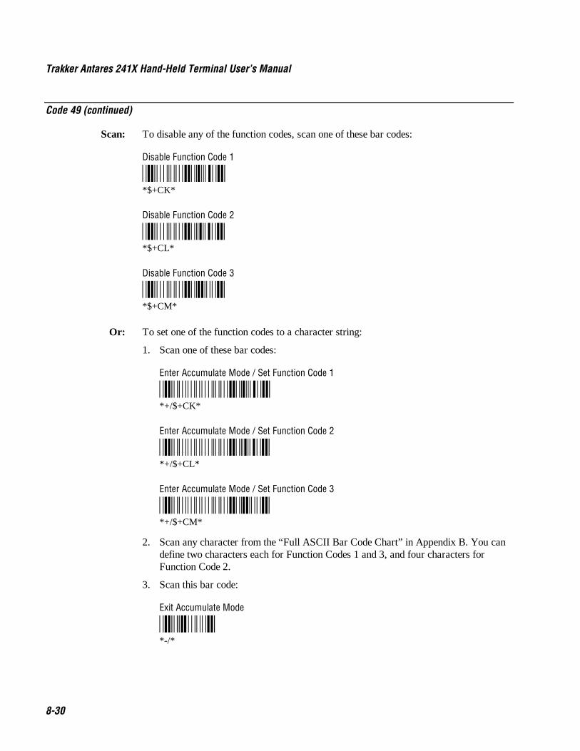
Trakker Antares 241X Hand-Held Terminal User’s Manual Co de 39 Nugget
8-30
Code 49 (continued)
Scan: To disable any of the function codes, scan one of these bar codes:
Disable Function Code 1
*$+CK**$+CK*
Disable Function Code 2
*$+CL**$+CL*
Disable Function Code 3
*$+CM**$+CM*
Or: To set one of the function codes to a character string:
1. Scan one of these bar codes:
Enter Accumulate Mode / Set Function Code 1
*+/$+CK**+/$+CK*
Enter Accumulate Mode / Set Function Code 2
*+/$+CL**+/$+CL*
Enter Accumulate Mode / Set Function Code 3
*+/$+CM**+/$+CM*
2. Scan any character from the “Full ASCII Bar Code Chart” in Appendix B. You candefine two characters each for Function Codes 1 and 3, and four characters forFunction Code 2.
3. Scan this bar code:
Exit Accumulate Mode
*-/**-/*

Co de 39 Nugget Configuration Command Reference
8-31
8Code 93
Purpose: Enables or disables decoding of Code 93 symbology. Code 93 is a variable length,continuous symbology that uses four element widths.
Syntax: CFdata
Acceptable values for data are:
0 Disabled1 Enabled
Default: Disabled
Menu System: From the Main Menu, choose Configuration Menu, then Symbologies Menu, and thenCode 93.
Scan: One of these bar codes:
Disable Code 93
*$+CF0**$+CF0*
Enable Code 93
*$+CF1**$+CF1*

Trakker Antares 241X Hand-Held Terminal User’s Manual Co de 39 Nugget
8-32
Code 128
Purpose: Enables or disables decoding of Code 128 symbology. Code 128 is a very high densityalphanumeric symbology that supports the extended ASCII character set. It is a variablelength, continuous code that uses multiple element widths.
Syntax: CHdata
Acceptable values for data are:
0 Disabled1 Standard Code 1282 UCC/EAN Code 1288 ISBT Code 128
Note: For help configuring ISBT Code 128, see the next section.
Default: Standard
Menu System: From the Main Menu, choose Configuration Menu, then Symbologies Menu, and thenCode 128.
Scan: One of these bar codes:
Disable Code 128 Enable Standard Code 128
*$+CH0* *$+CH1**$+CH0* *$+CH1*
Enable UCC/EAN Code 128 Enable ISBT Code 128
*$+CH2* *$+CH8**$+CH2* *$+CH8*
Other: If you configure Standard Code 128, the terminal will not decode Function Code 1characters in the first position of a bar code label. Any subsequent Function Code 1characters are translated to the ASCII GS character as a separator for variable lengthfields.
If you configure UCC/EAN Code 128, the terminal will decode a bar code label asStandard Code 128 unless one of the first two characters are a start character and aFunction Code 1. In this case, the bar code label is processed as described next:
1. The Function Code 1 character is not transmitted.
2. The three symbology ID characters, ]C1, are transmitted.
3. The remaining Code 128 characters are decoded as Standard Code 128.

Co de 39 Nugget Configuration Command Reference
8-33
8ISBT Code 128
Purpose: Enables and configures decoding of ISBT Code 128 symbology. ISBT Code 128 is theglobal bar code labeling standard for the blood banking industry. It is used to support theworld-wide distribution, tracking, and handling of blood bags and blood components.
For more information on ISBT Code 128, see the ISBT 128 Bar Code Symbology andApplication Specification for Labeling of Whole Blood and Blood Components preparedby the International Council for Commonality in Blood Banking Automation.
Syntax: CH8data
where data can be up to 10 digits selected from this list:
Digits Values Description
1 0 Symbology identifier (ID) disabled.
1 Symbology ID enabled. Output of ]C0 indicates a single ISBT Code128 bar code was read. Output of ]C4 indicates that a pair of ISBTCode 128 bar codes was read.
2 0 Concatenation disabled.
1 Restricted concatenation enabled.
3-4 See List* Left Data ID to be matched for restricted concatenation.
* List of valid combinations are:
=% Blood Groups and Rh=> Expiration Date&> Expiration Date and Time=* Collection Date&* Collection Date and Time=< ISBT Product Code=) Manufacturer ID&) Manufacturer Lot Number=& Concatenation Bar Code&< National Product Code&( National Special Test&! Unit Exclusion Status&; National Special Donor=n Donation ID Number where n is a value from 0 to 9 or
uppercase A through Z&n National Use Bar Code where n is a value from
lowercase a through z
5-6 See List* Right Data ID to be matched for restricted concatenation. See the listof valid combinations for digits 3 and 4.

Trakker Antares 241X Hand-Held Terminal User’s Manual Co de 39 Nugget
8-34
ISBT Code 128 (continued)
Digits Values Description
7-9 000-999 Bar code concatenation control parameters.
If digit 10 is “d,” digits 7 and 8 refer to the nominal distance inmillimeters between the stop characters of two bar code labels thatcan be concatenated, and digit 9 is the bar code label positioningtolerance. If the distance between the two bar code labels is outsidethis limit (assuming standard ISBT bar code print size), the bar codelabels will not be concatenated.
If digit 10 is “t,” digits 7, 8, and 9 are the decode time limit inmilliseconds. If both bar code labels are not decoded in the samebeam sweep within this time, the bar code labels are notconcatenated. This time parameter is only accurate to a 25-millisecond resolution.
10 d or t Identifies the concatenation control as either the distance “d”between bar code labels or the time “t” in which concatenated barcode labels must be decoded. See description for Digits 7-9.
Note: The Left Data ID and Right Data ID are used only with the restrictedconcatenation option. For example, the terminal will concatenate only those bar codelabels with data identifiers that match the configured data identifiers. The spacingbetween bar codes that can be concatenated must be between two and five characterwidths.
Default: Digit 1: Symbology ID disabledDigit 2: Concatenation disabled
Scan: To enable ISBT Code 128, scan this bar code:
Enable ISBT Code 128
*$+CH8**$+CH8*
Note: To scan the following bar codes, you must configure the terminal to use Code 39in Full ASCII mode. For help, see “Code 39” earlier in this chapter.
Or: To configure ISBT Code 128:
1. Scan this bar code:
Enter Accumulate Mode/Enable ISBT Code 128
*+/$+CH8**+/$+CH8*

Co de 39 Nugget Configuration Command Reference
8-35
8ISBT Code 128 (continued)
2. Scan one of these bar codes to disable or enable symbology ID:
Symbology ID Disabled Symbology ID Enabled
*0* *1**0* *1*
Note: Steps 3 through 9 are optional.
3. Scan one of these bar codes to disable or enable concatenation:
Disable Concatenation Enable Concatenation
*0* *1**0* *1*
If you disabled concatenation, go to Step 10.
4. Scan one of these bar codes to set the Left Data ID:
Blood Groups and Rh Expiration Date
*%H/E* *%H%I**=%* *=>*
Expiration Date and Time Collection Date
*/F%I* *%H/J**&>* *=**
Collection Date and Time ISBT Product Code
*/F/J* *%H%G**&** *=<*
Manufacturer ID Manufacturer Lot Number
*%H/I* */F/I**=)* *&)*
Concatenation Bar Code National Product Code
*%H/F* */F%G**=&* *&<*

Trakker Antares 241X Hand-Held Terminal User’s Manual Co de 39 Nugget
8-36
ISBT Code 128 (continued)
National Special Test Unit Exclusion Status
*/F/H* */F/A**&(* *&!*
National Special Donor Donation ID Number (See Note)
*/F%F* *%H**&;* *=*
National Use Bar Code (See Note)
*/F**&*
5. For the Donation ID Number or the National Use Bar Code, scan an alphanumericbar code from Appendix B.
• For the Donation ID Number, scan a value from 0 through 9 or uppercase Athrough Z.
• For the National Use Bar Code, scan a value from lowercase a through z.
6. Scan one of these bar codes to set the Right Data ID:
Blood Groups and Rh Expiration Date
*%H/E* *%H%I**=%* *=>*
Expiration Date and Time Collection Date
*/F%I* *%H/J**&>* *=**
Collection Date and Time ISBT Product Code
*/F/J* *%H%G**&** *=<*
Manufacturer ID Manufacturer Lot Number
*%H/I* */F/I**=)* *&)*
Concatenation Bar Code National Product Code
*%H/F* */F%G**=&* *&<*

Co de 39 Nugget Configuration Command Reference
8-37
8ISBT Code 128 (continued)
National Special Test Unit Exclusion Status
*/F/H* */F/A**&(* *&!*
National Special Donor Donation ID Number (See Note)
*/F%F* *%H**&;* *=*
National Use Bar Code (See Note)
*/F**&*
7. For the Donation ID Number or the National Use Bar Code, scan an alphanumericbar code from Appendix B.
• For the Donation ID Number, scan a value from 0 through 9 or uppercase Athrough Z.
• For the National Use Bar Code, scan a value from lowercase a through z.
8. Skip to Step 10 if you want to keep the default concatenation control parameters.
• The default concatenation distance is 16 mm ± 0 mm.
• The default concatenation decode time limit is 160 ms.
To set the concatenation decode time limit, scan these bar codes to set the time from001 to 999 ms. To set the concatenation distance, scan these bar codes to set thedistance from 00 to 99 mm and the tolerance from ± 1 to 9 mm.
*0* *1**0* *1*
*2* *3**2* *3*
*4* *5**4* *5*
*6* *7**6* *7*
*8* *9**8* *9*

Trakker Antares 241X Hand-Held Terminal User’s Manual Co de 39 Nugget
8-38
ISBT Code 128 (continued)
9. Scan one of these bar codes to set distance or time:
Distance Time
*+D* *+T**d* *t*
10. Scan this bar code to exit accumulate mode:
Exit Accumulate Mode
*-/**-/*
Co de 39 Nugget Configuration Command Reference
8-39
8Command Processing
Purpose: Command processing lets you disable or enable reader commands. For example, you candisable the Backlight command. There are two ways to enable or disable readercommands:
• Use the Command Processing configuration command described here.
• Use the Reader Command Menu option in the Configuration Menu of theTRAKKER Antares 2400 Menu System.
You may want to disable reader commands to prevent a user from accidentally entering acommand, or to use data that would otherwise be treated as a command. Any Code 39 orCode 93 bar code label that contains the 2-character to 4-character commands forCommand Processing is treated as a reader command unless the command is disabled.
If you want to disable or enable several commands, it is easier to use the menu system.For help, see Chapter 3, “Configuring the Terminal.” For a description of each readercommand that you can enable or disable with Command Processing, see Chapter 8,“Reader Command Reference.”
Syntax: DCdata
Acceptable values for data are:
0 Disable all reader commands1 Enable all reader commands2 Disable override3 Enable overridecommand0 Disable reader commandcommand1 Enable reader command
The override option is a temporary setting that lets you enable all the reader commandsfor as long as you need them. When you want to return to the previous configuration, youdisable the override.
Note: The Enable Override option is the only bar code label you can scan to enablereader commands if you have disabled all reader commands (DC0). You can also enablereader commands in the TRAKKER Antares 2400 Menu System.
Default: All reader commands enabled
Menu System: From the Main Menu, choose Configuration Menu, then Terminal Menu, and thenReader Commands.
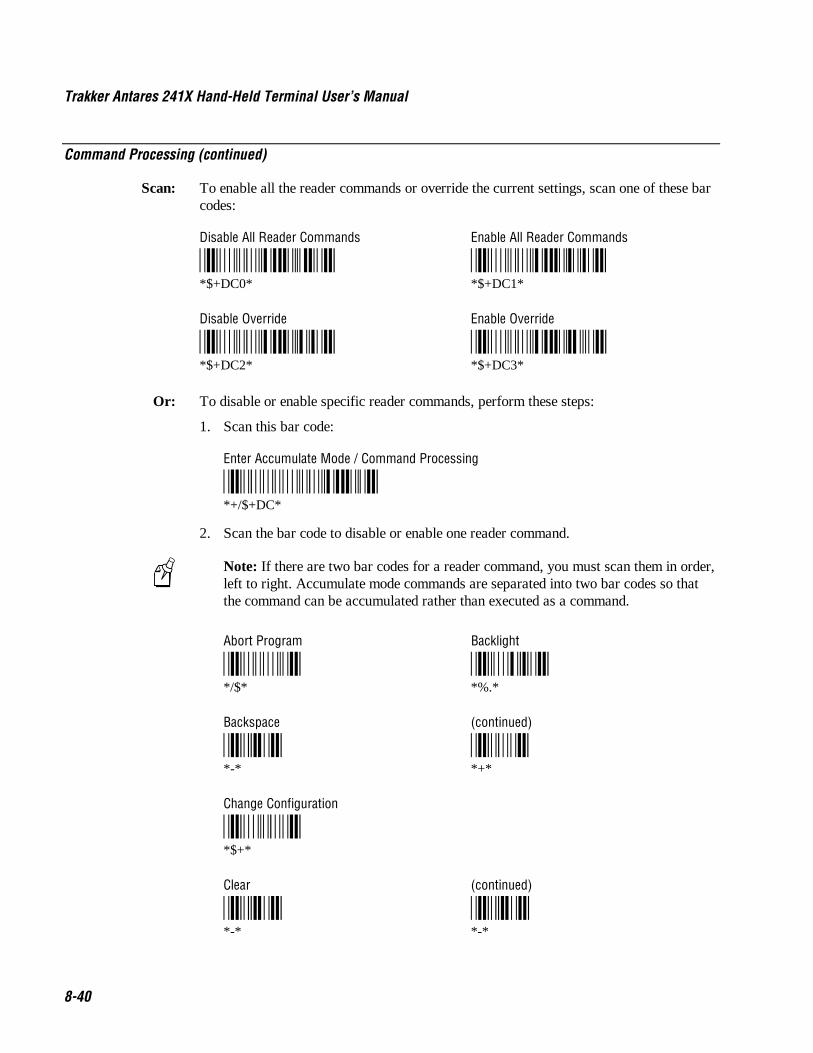
Trakker Antares 241X Hand-Held Terminal User’s Manual Co de 39 Nugget
8-40
Command Processing (continued)
Scan: To enable all the reader commands or override the current settings, scan one of these barcodes:
Disable All Reader Commands Enable All Reader Commands
*$+DC0* *$+DC1**$+DC0* *$+DC1*
Disable Override Enable Override
*$+DC2* *$+DC3**$+DC2* *$+DC3*
Or: To disable or enable specific reader commands, perform these steps:
1. Scan this bar code:
Enter Accumulate Mode / Command Processing
*+/$+DC**+/$+DC*
2. Scan the bar code to disable or enable one reader command.
Note: If there are two bar codes for a reader command, you must scan them in order,left to right. Accumulate mode commands are separated into two bar codes so thatthe command can be accumulated rather than executed as a command.
Abort Program Backlight
*/$* *%.**/$* *%.*
Backspace (continued)
*-* *+**-* *+*
Change Configuration
*$+**$+*
Clear (continued)
*-* *-**-* *-*

Co de 39 Nugget Configuration Command Reference
8-41
8Command Processing (continued)
Default/Save Configuration Delete File
*.+* *..--**.+* *..--*
Enter Accumulate Mode (continued)
*+* */**+* */*
Exit Accumulate Mode (continued)
*-* */**-* */*
Receive File Rename File
*.%* *...-**.%* *...-*
Reset Firmware Run Program
*-.* *//**-.* *//*
Scanner Trigger Off Scanner Trigger On
*/%* */.**/%* */.*
Set Time and Date Test and Service Mode
*/+* *..-.**/+* *..-.*
Transmit File
*%%**%%*
3. Scan one of these bar codes:
Disable the Command Enable the Command
*0* *1**0* *1*

Trakker Antares 241X Hand-Held Terminal User’s Manual Co de 39 Nugget
8-42
Command Processing (continued)
4. Repeat Steps 2 and 3 to disable or enable another reader command.
Note: You can accumulate up to 250 characters in the buffer. If the dataaccumulated exceeds 250 characters, you will hear an error beep and the terminalwill reject the last bar code read.
5. Scan this bar code:
Exit Accumulate Mode
*-/**-/*
Or: To disable or enable the ability to scan multiple-read labels, scan one of these bar codes:
Disable Multiple-Read Labels Enable Multiple-Read Labels
*$+DC 0* *$+DC 1**$+DC 0* *$+DC 1*

Co de 39 Nugget Configuration Command Reference
8-43
8Configuration Commands Via Serial Port
Purpose: Lets you control the data the terminal receives through the serial port. You can set thiscommand to execute reader and configuration commands received through the serial port,or treat all data as data without checking for special command syntax. There are threeoptions:
Disabled All data received through the serial port is treated as data. The terminal willnot execute reader or configuration commands sent or encoded in the data.
Enabled with TMF If the data is sent with the TMF (Terminal Message Format) header,the terminal will check for and execute reader or configuration commands receivedthrough the serial port. With TMF, you can execute reader and configuration commands,or send and receive data about the current terminal configuration.
Enabled without TMF The terminal will check for and execute all reader andconfiguration commands (i.e., Receive File reader command or Beep Volume changeconfiguration command).
Note: Before you can enable Configuration Commands Via Serial Port with or withoutTMF, you must enable the EOM command.
Syntax: YTn.data
where n is:
1 COM1 port
Acceptable values for data are:
0 Disabled1 Enabled with TMF2 Enabled without TMF
Default: Enabled without TMF
Menu System: From the Main Menu, choose Configuration Menu, then Communications Menu, andthen Serial Port.

Trakker Antares 241X Hand-Held Terminal User’s Manual Co de 39 Nugget
8-44
Configuration Commands Via Serial Port (continued)
Scan: One of these bar codes:
COM1 Commands Via Serial Port Disabled
*$+YT1.0**$+YT1.0*
COM1 Commands Via Serial Port Enabled With TMF
*$+YT1.1**$+YT1.1*
COM1 Commands Via Serial Port Enabled Without TMF
*$+YT1.2**$+YT1.2*
Other: For COM1 only. To provide compatibility with earlier Trakker Antares firmwareversions, you can also use this syntax:
ITdata
where data is a value from 0 to 2.

Co de 39 Nugget Configuration Command Reference
8-45
8Controller Connect Check Receive Timer
Purpose: During periods of inactivity on the 2415, the terminal still sends messages to theDCS 300 to check the RF connection. If no message is received within the time set for theController Connect Check Receive Timer, the terminal is no longer connected to theDCS 300 and the Connect LED blinks. The timer countdown resets each time a validmessage is received.
Power Management Tip: Intermec strongly recommends that you use the optimumsetting of 60 seconds to preserve the battery pack power.
Syntax: NPdata
Acceptable values for data are any number from 1 to 3600 seconds (60 minutes).
Default: 60 seconds
Menu System: From the Main Menu, choose Configuration Menu, then Communications Menu, andthen Advanced Network.
Scan: To set the default controller connect check receive timer, scan this bar code:
Default Controller Connect Check Receive Timer
*$+NP60**$+NP60*
Or: To set the controller connect check receive timer:
1. Scan this bar code:
Enter Accumulate Mode / Set Controller Connect Check Receive Timer
*+/$+NP**+/$+NP*

Trakker Antares 241X Hand-Held Terminal User’s Manual Co de 39 Nugget
8-46
Controller Connect Check Receive Timer (continued)
2. Scan a numeric value for data from these bar codes:
*0* *1**0* *1*
*2* *3**2* *3*
*4* *5**4* *5*
*6* *7**6* *7*
*8* *9**8* *9*
3. Scan this bar code:
Exit Accumulate Mode
*-/**-/*

Co de 39 Nugget Configuration Command Reference
8-47
8Controller Connect Check Send Timer
Purpose: During periods of inactivity on the 2415, the terminal still sends messages to theDCS 300 to check the RF connection. The terminal sends a message at the time intervalset for the Controller Connect Check Send Timer. The timer countdown resets each timea valid message is sent or received.
Power Management Tip: Intermec strongly recommends that you use the optimumsetting of 35 seconds to preserve the battery pack’s power.
Syntax: NQdata
Acceptable values for data are any number from 1 to 3600 seconds (60 minutes).
Default: 35 seconds
Menu System: From the Main Menu, choose Configuration Menu, then Communications Menu, andthen Advanced Network.
Scan: To set the default controller connect check send timer, scan this bar code:
Default Controller Connect Check Send Timer
*$+NQ35**$+NQ35*
Or: To set the controller connect check send timer:
1. Scan this bar code:
Enter Accumulate Mode / Set Controller Connect Check Send Timer
*+/$+NQ**+/$+NQ*

Trakker Antares 241X Hand-Held Terminal User’s Manual Co de 39 Nugget
8-48
Controller Connect Check Send Timer (continued)
2. Scan a numeric value for data from these bar codes:
*0* *1**0* *1*
*2* *3**2* *3*
*4* *5**4* *5*
*6* *7**6* *7*
*8* *9**8* *9*
3. Scan this bar code:
Exit Accumulate Mode
*-/**-/*

Co de 39 Nugget Configuration Command Reference
8-49
8Controller IP Address
Purpose: Defines the IP address assigned to the DCS 300 in your network. You assign a unique IPaddress to each device in a TCP/IP network. The controller IP address you set on the2415 must match the address that is set on the DCS 300.
If you plan to enable DHCP (Dynamic Host Configuration Protocol), you can set thecontroller IP address to any valid IP address. The terminal will locate and reset the IPaddress after you enable DHCP. For help, see “Dynamic Host Configuration Protocol”later in this chapter.
Syntax: NCn.n.n.n
where each n address segment is a number from 0 to 255. The controller IP address fieldconsists of four separate numbers, each separated by a period.
Note: The RF network cannot be activated if the first address segment in the IP addressis set to 0, 127, or a number greater than 223.
Default: 0.0.0.0
Menu System: From the Main Menu, choose Configuration Menu, then Communications Menu, andthen Primary Network.
Scan: To set the default controller IP address, scan this bar code:
Default Controller IP Address
*$+NC0.0.0.0**$+NC0.0.0.0*
Or: To set the controller IP address:
1. Scan this bar code:
Enter Accumulate Mode / Set Controller IP Address
*+/$+NC**+/$+NC*
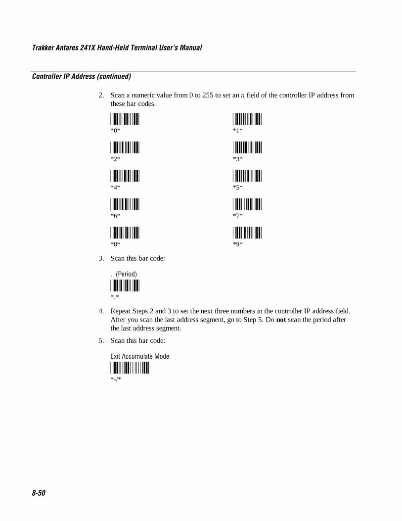
Trakker Antares 241X Hand-Held Terminal User’s Manual Co de 39 Nugget
8-50
Controller IP Address (continued)
2. Scan a numeric value from 0 to 255 to set an n field of the controller IP address fromthese bar codes.
*0* *1**0* *1*
*2* *3**2* *3*
*4* *5**4* *5*
*6* *7**6* *7*
*8* *9**8* *9*
3. Scan this bar code:
. (Period)
*.**.*
4. Repeat Steps 2 and 3 to set the next three numbers in the controller IP address field.After you scan the last address segment, go to Step 5. Do not scan the period afterthe last address segment.
5. Scan this bar code:
Exit Accumulate Mode
*-/**-/*

Co de 39 Nugget Configuration Command Reference
8-51
8Data Bits
Purpose: Sets the number of data bits the terminal uses when communicating with another device(i.e., host computer) through the serial port.
Syntax: YIn.data
where n is:
1 COM1 port
Acceptable values for data are:
7 7 data bits8 8 data bits
Default: 7
Menu System: From the Main Menu, choose Configuration Menu, then Communications Menu, andthen Serial Port.
Scan: One of these bar codes:
7 Data Bits for COM1
*$+YI1.7**$+YI1.7*
8 Data Bits for COM1
*$+YI1.8**$+YI1.8*
Other: For COM1 only. To provide compatibility with earlier Trakker Antares firmwareversions, you can also use this syntax:
IIdata
where data is a value or 7 or 8.

Trakker Antares 241X Hand-Held Terminal User’s Manual Co de 39 Nugget
8-52
Decode Security
Purpose: Defines the security level to use when decoding bar codes. When you select a lowerdecode security level, the terminal can decode bar codes with poorer print quality.
Note: Only use the low parameter as a temporary solution until you can improve the barcode label print quality.
Syntax: CSdata
Acceptable values for data are:
0 Low1 Moderate2 High
Default: Moderate
Menu System: From the Main Menu, choose Configuration, then Terminal Menu, and then Scanner.
Scan: One of these bar codes:
Low Decode Security
*$+CS0**$+CS0*
Moderate Decode Security
*$+CS1**$+CS1*
High Decode Security
*$+CS2**$+CS2*

Co de 39 Nugget Configuration Command Reference
8-53
8Default Router
Purpose: Defines the IP address that is assigned to the default router in the network. The routerprovides a software and hardware connection between two or more subnetworks thatpermits traffic to be routed from one subnetwork to another on the basis of the intendeddestinations of that traffic.
When the DCS 300 or host (TCP/IP network) is on a different subnetwork than the 2415,you must set this parameter. The default router must be on the same subnetwork as theterminal. The terminal uses the router address to send packets across the network to theDCS 300.
Syntax: NXn.n.n.n
where each n address segment is a number from 0 to 255. The default router address fieldconsists of four separate numbers, each separated by a period.
Note: The RF network cannot be activated if the first address segment in the IP addressis set to 0, 127, or a number greater than 223.
Default: No default router
Menu System: From the Main Menu, choose Configuration Menu, then Communications Menu, andthen Advanced Network.
Scan: To set the default value for the default router, scan this bar code:
No Default Router
*$+NX0.0.0.0**$+NX0.0.0.0*
Or: To set the default router address:
1. Scan this bar code:
Enter Accumulate Mode / Set Default Router
*+/$+NX**+/$+NX*

Trakker Antares 241X Hand-Held Terminal User’s Manual Co de 39 Nugget
8-54
Default Router (continued)
2. Scan a numeric value from 0 to 255 to set an n field of the default router addressfrom these bar codes.
*0* *1**0* *1*
*2* *3**2* *3*
*4* *5**4* *5*
*6* *7**6* *7*
*8* *9**8* *9*
3. Scan this bar code:
. (Period)
*.**.*
4. Repeat Steps 2 and 3 to set the next three numbers in the default router address field.After you scan the last address segment, go to Step 5. Do not scan the period afterthe last address segment.
5. Scan this bar code:
Exit Accumulate Mode
*-/**-/*
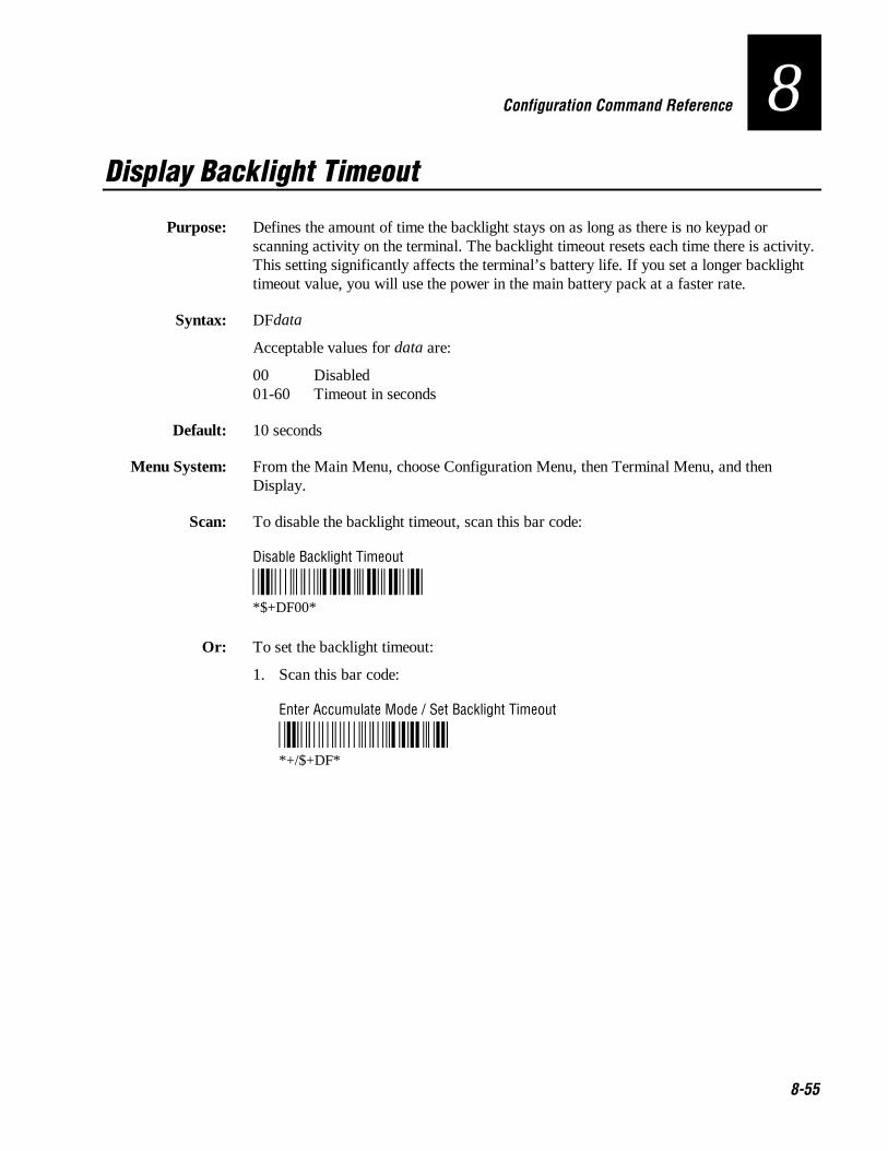
Co de 39 Nugget Configuration Command Reference
8-55
8Display Backlight Timeout
Purpose: Defines the amount of time the backlight stays on as long as there is no keypad orscanning activity on the terminal. The backlight timeout resets each time there is activity.This setting significantly affects the terminal’s battery life. If you set a longer backlighttimeout value, you will use the power in the main battery pack at a faster rate.
Syntax: DFdata
Acceptable values for data are:
00 Disabled01-60 Timeout in seconds
Default: 10 seconds
Menu System: From the Main Menu, choose Configuration Menu, then Terminal Menu, and thenDisplay.
Scan: To disable the backlight timeout, scan this bar code:
Disable Backlight Timeout
*$+DF00**$+DF00*
Or: To set the backlight timeout:
1. Scan this bar code:
Enter Accumulate Mode / Set Backlight Timeout
*+/$+DF**+/$+DF*

Trakker Antares 241X Hand-Held Terminal User’s Manual Co de 39 Nugget
8-56
Display Backlight Timeout (continued)
2. Scan a two-digit numeric value for data from these bar codes.
*0* *1**0* *1*
*2* *3**2* *3*
*4* *5**4* *5*
*6* *7**6* *7*
*8* *9**8* *9*
3. Scan this bar code:
Exit Accumulate Mode
*-/**-/*

Co de 39 Nugget Configuration Command Reference
8-57
8Display Contrast
Purpose: Defines the contrast (low or high) of the characters against the terminal screen. When thecontrast is set to 0, the characters are bright against a bright background. When thecontrast is set to 7, the characters are dark against a dark background.
Syntax: DJdata
Acceptable values for data are 0 (low) to 7 (high).
Default: 3
Menu System: From the Main Menu, choose Configuration Menu, then Terminal Menu, and thenDisplay.
Scan: One of these bar codes:
0 - Light Display Contrast 1
*$+DJ0* *$+DJ1**$+DJ0* *$+DJ1*
2 3 - Maximum Display Contrast
*$+DJ2* *$+DJ3**$+DJ2* *$+DJ3*
4 5
*$+DJ4* *$+DJ5**$+DJ4* *$+DJ5*
6 7 - Dark Display Contrast
*$+DJ6* *$+DJ7**$+DJ6* *$+DJ7*
Or: Scan one of these bar codes repeatedly to change the display contrast:
Lighter Display Contrast Darker Display Contrast
*$+DJ8* *$+DJ9**$+DJ8* *$+DJ9*

Trakker Antares 241X Hand-Held Terminal User’s Manual Co de 39 Nugget
8-58
Display Font Grid Type
Purpose: Sets the number of rows and columns that are on the terminal screen. You can set aregular size font grid (8x8), a font grid with double-height characters (8x16), or a fontgrid with double-width and double-height characters (16x16).
Syntax: DTdata
Acceptable values for data are:
0 8 pixels by 8 pixels (8x8) font grid1 8 pixels wide by 16 pixels high (8x16) font grid2 16 pixels wide by 16 pixels high (16x16) font grid
Default: 8x8
Menu System: From the Main Menu, choose Configuration Menu, then Terminal Menu, and thenDisplay.
Scan: One of these bar codes:
Set Display Font Grid Type to 8x8
*$+DT0**$+DT0*
Set Display Font Grid Type to 8x16
*$+DT1**$+DT1*
Set Display Font Grid Type to 16x16
*$+DT2**$+DT2*

Co de 39 Nugget Configuration Command Reference
8-59
8Display Row Spacing
Purpose: Sets the row spacing on the terminals. Row spacing lets you define the amount ofadditional space (scan lines) between the lines on the screen. The number of scan lines istwo times the value you set for the row spacing. A scan line is a row of pixels. Forexample, a row spacing of 8 adds 16 blank scan lines between lines on the screen
Syntax: DLdata
Acceptable values for data are any number from 0 to 8.
Default: 0
Menu System: From the Main Menu, choose Configuration Menu, then Terminal Menu, and thenDisplay.
Scan: One of these bar codes:
Set Row Spacing to 0 Set Row Spacing to 1
*$+DL0* *$+DL1**$+DL0* *$+DL1*
Set Row Spacing to 2 Set Row Spacing to 3
*$+DL2* *$+DL3**$+DL2* *$+DL3*
Set Row Spacing to 4 Set Row Spacing to 5
*$+DL4* *$+DL5**$+DL4* *$+DL5*
Set Row Spacing to 6 Set Row Spacing to 7
*$+DL6* *$+DL7**$+DL6* *$+DL7*
Set Row Spacing to 8
*$+DL8**$+DL8*

Trakker Antares 241X Hand-Held Terminal User’s Manual Co de 39 Nugget
8-60
Display Video Mode
Purpose: Sets the Display Video mode that is used on the terminal screen. You can set the DisplayVideo mode to original, normal, or inverse. Original displays black characters on a whitebackground. Normal displays black characters on a white background. Inverse displayswhite characters on a black background.
Syntax: DNdata
Acceptable values for data are:
0 Original1 Normal2 Inverse
Default: Original
Menu System: From the Main Menu, choose Configuration Menu, then Terminal Menu, and thenDisplay.
Scan: One of these bar codes:
Original Display Video Mode
*$+DN0**$+DN0*
Normal Display Video Mode
*$+DN1**$+DN1*
Inverse Display Video Mode
*$+DN2**$+DN2*

Co de 39 Nugget Configuration Command Reference
8-61
8Domain
Purpose: (OpenAir radio parameter) Defines an RF subnetwork. To communicate, all accesspoints and 2415s in the subnetwork must have the same domain number. You can roambetween access points as long as all of the RF devices have the same domain number.Youcan assign different domain numbers if you want to establish different RF subnetworks inthe same area.
Syntax: RWdata
Acceptable values for data are any number from 0 to 15.
Menu System: From the Main Menu, choose Configuration Menu, then Communications Menu, andthen Radio.
Default: 0
Scan: To set the default domain, scan this bar code:
Default Domain
*$+RW0**$+RW0
Or: 1. Scan this bar code:
Enter Accumulate Mode / Set Domain
*+/$+RW**+/$+RW*

Trakker Antares 241X Hand-Held Terminal User’s Manual Co de 39 Nugget
8-62
Domain (continued)
2. Scan a numeric value for data from these bar codes:
*0* *1**0* *1*
*2* *3**2* *3*
*4* *5**4* *5*
*6* *7**6* *7*
*8* *9**8* *9*
3. Scan this bar code:
Exit Accumulate Mode
*-/**-/*
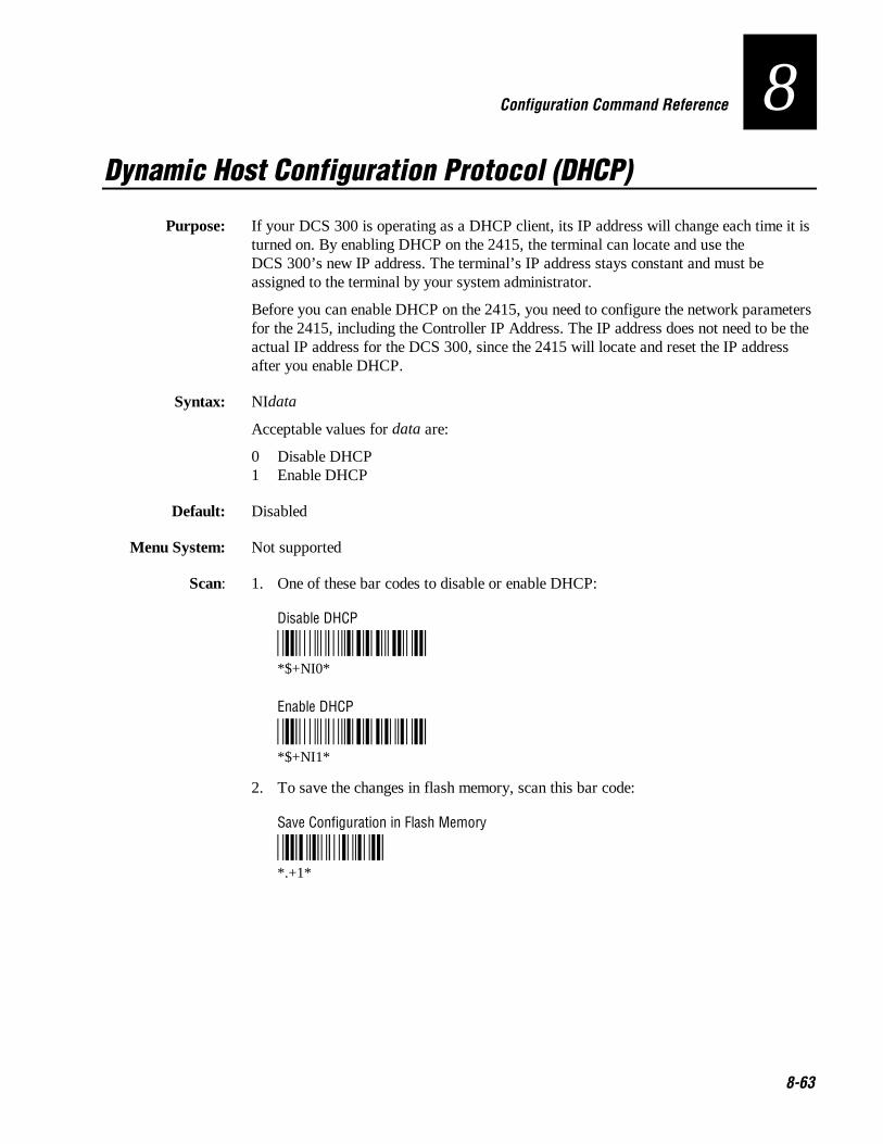
Co de 39 Nugget Configuration Command Reference
8-63
8Dynamic Host Configuration Protocol (DHCP)
Purpose: If your DCS 300 is operating as a DHCP client, its IP address will change each time it isturned on. By enabling DHCP on the 2415, the terminal can locate and use theDCS 300’s new IP address. The terminal’s IP address stays constant and must beassigned to the terminal by your system administrator.
Before you can enable DHCP on the 2415, you need to configure the network parametersfor the 2415, including the Controller IP Address. The IP address does not need to be theactual IP address for the DCS 300, since the 2415 will locate and reset the IP addressafter you enable DHCP.
Syntax: NIdata
Acceptable values for data are:
0 Disable DHCP1 Enable DHCP
Default: Disabled
Menu System: Not supported
Scan: 1. One of these bar codes to disable or enable DHCP:
Disable DHCP
*$+NI0**$+NI0*
Enable DHCP
*$+NI1**$+NI1*
2. To save the changes in flash memory, scan this bar code:
Save Configuration in Flash Memory
*.+1**.+1*

Trakker Antares 241X Hand-Held Terminal User’s Manual Co de 39 Nugget
8-64
End of Message (EOM)
Purpose: Attaches an EOM to the end of a data block to indicate the end of data transmission toand from a terminal. When EOM is disabled, the terminal communicates in Charactermode. When EOM is enabled, the terminal communicates in Frame mode.
You must configure a value for EOM before you can set these other serialcommunications commands:
• Configuration Commands Via Serial Port
• Handshake
• LRC
• Start of Message (SOM)
EOM cannot equal the same value that is set for SOM. You cannot set EOM to any ofthese values:
• AFF (ACK) • REQ (ENQ)• DLE • SEL• NEG (NAK) • XOFF• Poll • XON• RES (EOT)
Syntax: YZn.data
where n is:
1 COM1 port
Acceptable values for data are one or two ASCII characters.
Default: \x03 (hexadecimal value for ETX)
Menu System: From the Main Menu, choose Configuration Menu, then Communications Menu, andthen Serial Port.
Scan: To set the default EOM, scan this bar code:
Note: To scan these bar code labels, you must configure the terminal to use Code 39 inFull ASCII mode. For help, see “Code 39” earlier in this chapter.
Default EOM for COM1
*/D/KYZ1.$C**$+YZ1.$C*

Co de 39 Nugget Configuration Command Reference
8-65
8End of Message (continued)
Or: To disable EOM, scan this bar code:
Disable EOM for COM1
*$+YZ1.**$+YZ1.*
Or: To set EOM to one or two ASCII characters for one serial port:
1. Scan this bar code:
Enter Accumulate Mode / Set EOM
*/K/O/D/KYZ**+/$+YZ*
2. Scan one of these bar codes to set the COM port:
COM1
*1/N**1.*
3. Scan one or two bar codes for data from the “Full ASCII Bar Code Chart” inAppendix B.
4. Scan this bar code:
Exit Accumulate Mode
*/M/O**-/*
Other: For COM1 only. To provide compatibility with earlier Trakker Antares firmwareversions, you can also use this syntax:
PFdata
where data is one or two ASCII characters.

Trakker Antares 241X Hand-Held Terminal User’s Manual Co de 39 Nugget
8-66
Flash Memory Configuration
Purpose: Configures the use of the optional 2MB flash memory. If you have a terminal with the4MB flash memory option, you can configure the extra 2MB of flash memory either as adrive D or you can use it to store a 2MB double-byte font. If you configure the flashmemory as drive D, use this drive to store large lookup tables and data files. You canstore up to 128 files.
After you configure the flash memory, you must save the configuration in flash memoryand boot the terminal for the change to take effect.
Syntax: FFdata
Acceptable values for data are:
0 Configure flash memory for double-byte fonts32 Configure flash memory as drive D
Default: Configure flash memory for double-byte fonts
Menu System: Not supported
Scan: 1. Scan one of these bar codes:
Configure Flash Memory for Double-Byte Fonts
*$+FF0**$+FF0*
Configure Flash Memory as Drive D
*$+FF32**$+FF32*
2. Scan this bar code to save the configuration change in flash memory:
Save Configuration in Flash Memory
*.+1**.+1*
3. Scan this bar code to boot the terminal and use the flash memory to store double-bytefonts or as drive D:
Reset Firmware
*-.**-.*

Co de 39 Nugget Configuration Command Reference
8-67
8Flash Memory Configuration (continued)
Note: When you boot or reset the terminal, any fonts or files in flash memory areerased.
4. If you configured the flash memory to store double-byte fonts, use the TrakkerAntares Font Editor to download the double-byte font set to the terminal. See yourlocal Intermec sales representative for information about the Trakker Antares FontEditor.
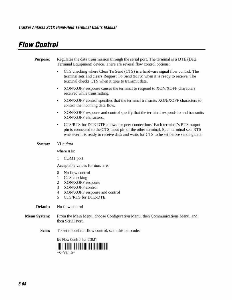
Trakker Antares 241X Hand-Held Terminal User’s Manual Co de 39 Nugget
8-68
Flow Control
Purpose: Regulates the data transmission through the serial port. The terminal is a DTE (DataTerminal Equipment) device. There are several flow control options:
• CTS checking where Clear To Send (CTS) is a hardware signal flow control. Theterminal sets and clears Request To Send (RTS) when it is ready to receive. Theterminal checks CTS when it tries to transmit data.
• XON/XOFF response causes the terminal to respond to XON/XOFF charactersreceived while transmitting.
• XON/XOFF control specifies that the terminal transmits XON/XOFF characters tocontrol the incoming data flow.
• XON/XOFF response and control specify that the terminal responds to and transmitsXON/XOFF characters.
• CTS/RTS for DTE-DTE allows for peer connections. Each terminal’s RTS outputpin is connected to the CTS input pin of the other terminal. Each terminal sets RTSwhenever it is ready to receive data and waits for CTS to be set before sending data.
Syntax: YLn.data
where n is:
1 COM1 port
Acceptable values for data are:
0 No flow control1 CTS checking2 XON/XOFF response3 XON/XOFF control4 XON/XOFF response and control5 CTS/RTS for DTE-DTE
Default: No flow control
Menu System: From the Main Menu, choose Configuration Menu, then Communications Menu, andthen Serial Port.
Scan: To set the default flow control, scan this bar code:
No Flow Control for COM1
*$+YL1.0**$+YL1.0*
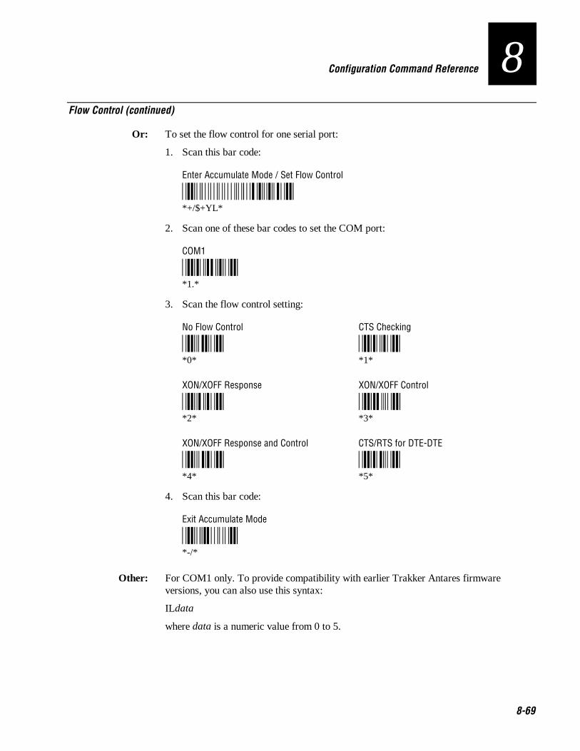
Co de 39 Nugget Configuration Command Reference
8-69
8Flow Control (continued)
Or: To set the flow control for one serial port:
1. Scan this bar code:
Enter Accumulate Mode / Set Flow Control
*+/$+YL**+/$+YL*
2. Scan one of these bar codes to set the COM port:
COM1
*1.**1.*
3. Scan the flow control setting:
No Flow Control CTS Checking
*0* *1**0* *1*
XON/XOFF Response XON/XOFF Control
*2* *3**2* *3*
XON/XOFF Response and Control CTS/RTS for DTE-DTE
*4* *5**4* *5*
4. Scan this bar code:
Exit Accumulate Mode
*-/**-/*
Other: For COM1 only. To provide compatibility with earlier Trakker Antares firmwareversions, you can also use this syntax:
ILdata
where data is a numeric value from 0 to 5.

Trakker Antares 241X Hand-Held Terminal User’s Manual Co de 39 Nugget
8-70
Handshake
Purpose: Enables or disables the handshake event that is an affirmative acknowledge to a messagereceived through the serial port.
Note: Before you can enable Handshake, you must configure the EOM command.Handshake is also referred to as AFF (affirmative acknowledge) on other Intermecdevices.
Syntax: YJn.data
where n is:
1 COM1 port
Acceptable values for data are:
Disabled No ACK or NAK transmittedEnabled \x06 (hexadecimal value for ACK)
Default: Disabled
Menu System: From the Main Menu, choose Configuration Menu, then Communications Menu, andthen Serial Port.
Scan: One of these bar codes:
Note: To scan these bar code labels, you must configure the terminal to use Code 39 inFull ASCII mode. For help, see “Code 39” earlier in this chapter.
Disable Handshake for COM1
*/D/KYJ1.**$+YJ1.*
Enable Handshake (Set to ACK) for COM1
*/D/KYJ1.$F**$+YJ1.$F*
Other: For COM1 only. To provide compatibility with earlier Trakker Antares firmwareversions, you can also use this syntax:
PGdata
where data is disabled or enabled (set to ACK).

Co de 39 Nugget Configuration Command Reference
8-71
8Host IP Address
Purpose: Defines the IP address assigned to the host computer in the TCP/IP network. You assignan IP address to each device in a TCP/IP direct connect network. The host IP address youset on the 2415 must match the address that is set on the host.
Syntax: NCn.n.n.n
where each n address segment is a number from 0 to 255. The host IP address fieldconsists of four separate numbers, each separated by a period.
Note: The RF network cannot be activated if the first address segment in the IP addressis set to 0, 127, or a number greater than 223.
Default: 0.0.0.0
Menu System: From the Main Menu, choose Configuration Menu, then Communications Menu, andthen Primary Network.
Scan: To set the default host IP address, scan this bar code:
Default Host IP Address
*$+NC0.0.0.0**$+NC0.0.0.0*
Or: To set the host IP address:
1. Scan this bar code:
Enter Accumulate Mode / Set Host IP Address
*+/$+NC**+/$+NC*

Trakker Antares 241X Hand-Held Terminal User’s Manual Co de 39 Nugget
8-72
Host IP Address (continued)
2. Scan a numeric value from 0 to 255 to set an n field of the host IP address from thesebar codes.
*0* *1**0* *1*
*2* *3**2* *3*
*4* *5**4* *5*
*6* *7**6* *7*
*8* *9**8* *9*
3. Scan this bar code:
. (Period)
*.**.*
4. Repeat Steps 2 and 3 to set the next three numbers in the host IP address field. Afteryou scan the last address segment, go to Step 5. Do not scan the period after the lastaddress segment.
5. Scan this bar code:
Exit Accumulate Mode
*-/**-/*

Co de 39 Nugget Configuration Command Reference
8-73
8Inactivity Timeout
Purpose: (OpenAir radio parameter) Defines the amount of time the radio on the 2415 waits to gointo a low power state. If no data is sent or received within the inactivity timeout periodset, the radio goes into a low power state to conserve battery power. If you set a highvalue, the radio stays on longer at a higher power rate and uses battery power at a fasterrate.
Power Management Tip: Intermec strongly recommends that you use the optimuminactivity timeout of 5 seconds to preserve the battery pack power.
Syntax: RYdata
Acceptable values for data are:
0 Radio never turns off1-51 RF inactivity timeout in seconds multiplied by a value of 5
where data=1 sets a timeout delay of 5 seconds, data=2 sets a timeout delay of 10seconds, and so on, up to data=51 for a timeout delay of 255 seconds.
Menu System: From the Main Menu, choose Configuration Menu, then Communications Menu, andthen Radio.
Default: 5 seconds
Scan: To set the default inactivity timeout to 5 seconds, scan this bar code:
Default Inactivity Timeout
*$+RY1**$+RY1*
Or: To set the inactivity timeout:
1. Scan this bar code:
Enter Accumulate Mode / Set Inactivity Timeout
*+/$+RY**+/$+RY*

Trakker Antares 241X Hand-Held Terminal User’s Manual Co de 39 Nugget
8-74
Inactivity Timeout (continued)
2. Scan a numeric value for data from these bar codes:
*0* *1**0* *1*
*2* *3**2* *3*
*4* *5**4* *5*
*6* *7**6* *7*
*8* *9**8* *9*
3. Scan this bar code:
Exit Accumulate Mode
*-/**-/*

Co de 39 Nugget Configuration Command Reference
8-75
8Interleaved 2 of 5
Purpose: Enables or disables decoding of Interleaved 2 of 5 (I 2 of 5) symbology. I 2 of 5 is ahigh-density, self-checking, continuous numeric symbology. It is mainly used in inventorydistribution and the automobile industry.
Enabling I 2 of 5 automatically disables Code 2 of 5.
Syntax: CAdata
Acceptable values for data are:
0 Disabled2-32 Fixed length (even number only)97 Variable length without a check digit98 Case code (6 or 14) with a check digit99 Variable length with a check digit
CautionUsing the variable length without a check digit configuration option can causesubstitution errors.
ConseilDes erreurs de substitution peuvent survenir si vous utilisez la longueur variablesans option de vérification de configuration de chiffres.
Default: Disabled
Menu System: From the Main Menu, choose Configuration Menu, then Symbologies Menu, and then2 of 5/I 2 of 5.
Scan: One of these bar codes:
Disable Interleaved 2 of 5 Enable Variable Length Without a Check Digit
*$+CA0* *$+CA97**$+CA0* *$+CA97*
Enable Variable Length With a Check Digit Enable Case Code With a Check Digit
*$+CA99* *$+CA98**$+CA99* *$+CA98*

Trakker Antares 241X Hand-Held Terminal User’s Manual Co de 39 Nugget
8-76
Interleaved 2 of 5 (continued)
Or: To set Interleaved 2 of 5 to a fixed length:
1. Scan this bar code:
Enter Accumulate Mode / Set Fixed Length
*+/$+CA**+/$+CA*
2. Scan a numeric value for data from these bar codes. (Use even numbers 2-32 only.)
*0* *1**0* *1*
*2* *3**2* *3*
*4* *6**4* *6*
*8**8*
3. Scan this bar code:
Exit Accumulate Mode
*-/**-/*

Co de 39 Nugget Configuration Command Reference
8-77
8Keypad Caps Lock
Purpose: Turns the caps lock on and off. With the caps lock turned on, all alphabetic charactersyou type on the keypad will be uppercase or capital letters.
Syntax: KAdata
Acceptable values for data are:
0 Caps lock off1 Caps lock on
Default: Caps lock off
Menu System: From the Main Menu, choose Configuration Menu, then Terminal Menu, and thenKeypad.
Scan: One of these bar codes:
Caps Lock Off
*$+KA0**$+KA0*
Caps Lock On
*$+KA1**$+KA1*

Trakker Antares 241X Hand-Held Terminal User’s Manual Co de 39 Nugget
8-78
Keypad Clicker
Purpose: Enables or disables the keypad clicker. The terminal sounds a click each time you press akey or decode a row of a two-dimensional symbology.
Note: If the Beep Volume command is set to off, you will not hear any audio signalsincluding the keyclick.
Syntax: KCdata
Acceptable values for data are:
0 Disable keypad clicker1 Enable keypad clicker
Default: Enabled
Menu System: From the Main Menu, choose Configuration Menu, then Terminal Menu, and thenKeypad.
Scan: One of these bar codes:
Disable Keypad Clicker
*$+KC0**$+KC0*
Enable Keypad Clicker
*$+KC1**$+KC1*

Co de 39 Nugget Configuration Command Reference
8-79
8Keypad Type
Purpose: The keypad type is initially configured in the terminal’s firmware at the Intermec factory.If you change the keypad overlay, you must configure the keypad type to match the newkeypad overlay.
After you change the keypad type, you must save the configuration in flash memory andboot the terminal for the change to take effect.
Note: With the programmable or international keypad, you can access all the charactersin the “Trakker Antares Terminal Font Set” in Appendix C.
Syntax: KTdata
Acceptable values for data are:
55-Key 37-Key
0 Hardware (factory default) 0 Hardware (factory default)
L Programmable/international keypad P Programmable/international keypad
M TE keypad Q TE keypad
Default: Hardware default
Menu System: From the Main Menu, choose Configuration Menu, then Terminal Menu, and thenKeypad.
Scan: 1. Scan one of these bar codes:
Set Keypad Type to Hardware Default
*$+KT0**$+KT0*
Set 55-Key Keypad Type to Programmable/International Keypad
*$+KTL**$+KTL*
Set 55-Key Keypad Type to TE Keypad
*$+KTM**$+KTM*
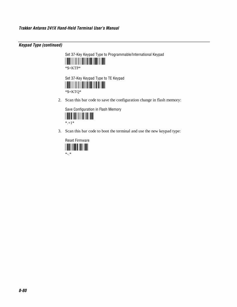
Trakker Antares 241X Hand-Held Terminal User’s Manual Co de 39 Nugget
8-80
Keypad Type (continued)
Set 37-Key Keypad Type to Programmable/International Keypad
*$+KTP**$+KTP*
Set 37-Key Keypad Type to TE Keypad
*$+KTQ**$+KTQ*
2. Scan this bar code to save the configuration change in flash memory:
Save Configuration in Flash Memory
*.+1**.+1*
3. Scan this bar code to boot the terminal and use the new keypad type:
Reset Firmware
*-.**-.*
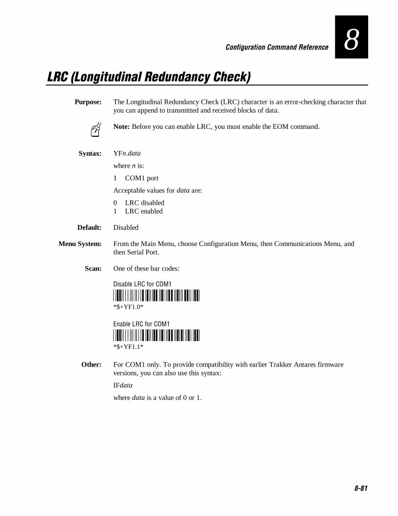
Co de 39 Nugget Configuration Command Reference
8-81
8LRC (Longitudinal Redundancy Check)
Purpose: The Longitudinal Redundancy Check (LRC) character is an error-checking character thatyou can append to transmitted and received blocks of data.
Note: Before you can enable LRC, you must enable the EOM command.
Syntax: YFn.data
where n is:
1 COM1 port
Acceptable values for data are:
0 LRC disabled1 LRC enabled
Default: Disabled
Menu System: From the Main Menu, choose Configuration Menu, then Communications Menu, andthen Serial Port.
Scan: One of these bar codes:
Disable LRC for COM1
*$+YF1.0**$+YF1.0*
Enable LRC for COM1
*$+YF1.1**$+YF1.1*
Other: For COM1 only. To provide compatibility with earlier Trakker Antares firmwareversions, you can also use this syntax:
IFdata
where data is a value of 0 or 1.

Trakker Antares 241X Hand-Held Terminal User’s Manual Co de 39 Nugget
8-82
Maximum Retries
Purpose: Defines the number of times the 2415 will attempt to send a disconnect request messageto the DCS 300. The 2415 sends connect and disconnect request messages to theDCS 300 when you turn the terminal on and off.
Tip: Intermec strongly recommends that you use the optimum setting of 7 retries.
Syntax: NRdata
Acceptable values for data are:
0 2415 retries indefinitely1-99 Number of retries
Default: 7
Menu System: From the Main Menu, choose Configuration Menu, then Communications Menu, andthen Advanced Network.
Scan: To set the default number of maximum retries, scan this bar code:
Default Maximum Retries
*$+NR7**$+NR7*
Or: To set the maximum retries:
1. Scan this bar code:
Enter Accumulate Mode / Set Maximum Retries
*+/$+NR**+/$+NR*

Co de 39 Nugget Configuration Command Reference
8-83
8Maximum Retries (continued)
2. Scan a numeric value for data from these bar codes:
*0* *1**0* *1*
*2* *3**2* *3*
*4* *5**4* *5*
*6* *7**6* *7*
*8* *9**8* *9*
3. Scan this bar code:
Exit Accumulate Mode
*-/**-/*

Trakker Antares 241X Hand-Held Terminal User’s Manual Co de 39 Nugget
8-84
Maximum Sleep Duration
Purpose: (IEEE 802.11 DS radio parameter) Specifies the maximum amount of time the radio isallowed to sleep.
Note: Before you set the reservation, you must set the Power Management command toenable.
Syntax: LHdata
Default: 100
Acceptable values for data are from 0 to 65535 Kusecs. A Kusec is approximately 1 ms.
Menu System: From the Main Menu, choose Configuration Menu, then Communications Menu, andthen Radio.
Scan: To set the default maximum sleep duration, scan this bar code:
Default Max Sleep Duration
*$+LH100**$+LH100
Or: To set the maximum sleep duration:
1. Scan this bar code:
Enter Accumulate Mode / Set Max Sleep Duration
*+/$+LH**+/$+LH*

Co de 39 Nugget Configuration Command Reference
8-85
8Maximum Sleep Duration (continued)
2. Scan a numeric value for data from these bar codes:
*0* *1**0* *1*
*2* *3**2* *3*
*4* *5**4* *5*
*6* *7**6* *7*
*8* *9**8* *9*
3. Scan this bar code:
Exit Accumulate Mode
*-/**-/*
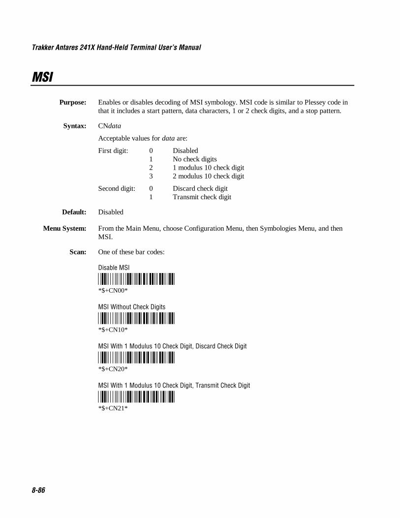
Trakker Antares 241X Hand-Held Terminal User’s Manual Co de 39 Nugget
8-86
MSI
Purpose: Enables or disables decoding of MSI symbology. MSI code is similar to Plessey code inthat it includes a start pattern, data characters, 1 or 2 check digits, and a stop pattern.
Syntax: CNdata
Acceptable values for data are:
First digit: 0 Disabled1 No check digits2 1 modulus 10 check digit3 2 modulus 10 check digit
Second digit: 0 Discard check digit1 Transmit check digit
Default: Disabled
Menu System: From the Main Menu, choose Configuration Menu, then Symbologies Menu, and thenMSI.
Scan: One of these bar codes:
Disable MSI
*$+CN00**$+CN00*
MSI Without Check Digits
*$+CN10**$+CN10*
MSI With 1 Modulus 10 Check Digit, Discard Check Digit
*$+CN20**$+CN20*
MSI With 1 Modulus 10 Check Digit, Transmit Check Digit
*$+CN21**$+CN21*

Co de 39 Nugget Configuration Command Reference
8-87
8MSI (continued)
MSI With 2 Modulus 10 Check Digits, Discard Check Digits
*$+CN30**$+CN30*
MSI With 2 Modulus 10 Check Digits, Transmit Check Digits
*$+CN31**$+CN31*

Trakker Antares 241X Hand-Held Terminal User’s Manual Co de 39 Nugget
8-88
Network Activate
Purpose: Enables or disables network communications between the 2415 and other devices in theRF network. When you enable this parameter, the terminal attempts to establishcommunications with the DCS 300 or host computer. You must enable this parameter forRF data collection. When you disable this parameter, the network is disabled, no RFcommunications are provided, and the radio is turned off.
Syntax: NAdata
Acceptable values for data are:
0 Disabled1 Enabled (RF network communications)
Menu System: From the Main Menu, choose Configuration Menu, then Communications Menu, andthen Primary Network.
Default: Disabled
Scan: One of these bar codes:
Disable RF Network Communications
*$+NA0**$+NA0*
Enable RF Network Communications
*$+NA1**$+NA1*

Co de 39 Nugget Configuration Command Reference
8-89
8Network Loopback
Purpose: Transmits all messages received from the DCS 300 back to the DCS 300. Messagesreceived by the radio are not passed on to the 2415 applications unless they areconfiguration commands. Messages continue to be looped back to the DCS 300 as longas this feature is enabled. Messages originating from the 2415 are still transmitted to theDCS 300.
Use the Network Loopback parameter to troubleshoot RF communications problems.
Syntax: NLdata
Acceptable values for data are:
0 Disabled1 Enabled
Default: Disabled
Menu System: From the Main Menu, choose Configuration Menu, then Communications Menu, andthen Advanced Network.
Scan: One of these bar codes:
Disable Network Loopback
*$+NL0**$+NL0*
Enable Network Loopback
*$+NL1**$+NL1*

Trakker Antares 241X Hand-Held Terminal User’s Manual Co de 39 Nugget
8-90
Network Name
Purpose: (IEEE 802.11 DS radio parameter) Defines an RF subnetwork. To communicate, allaccess points and 2415s in the subnetwork must have the same network name, which iscase-sensitive. You can roam between access points as long as all of the RF devices havethe same network name.You can assign different network names if you want to establishdifferent RF subnetworks in the same area.
If you set this parameter to ANY, then any 2415s can associate with any access point,regardless of the access point network name.
Syntax: LAdata
Acceptable values for data are up to 32 ASCII characters.
Default: INTERMEC
Menu System: From the Main Menu, choose Configuration Menu, then Communications Menu, andthen Radio.
Scan: To set the default network name, scan this bar code:
Default Network Name
*$+LAINTERMEC**$+LAINTERMEC*
Or: To set the network name to “ANY,” scan this bar code label:
Set Network Name to ANY
*$+LAANY**$+LAANY*
Or: To set the network name to an ASCII character string:
1. Scan this bar code:
Enter Accumulate Mode / Set Network Name
*+/$+LA**+/$+LA*
2. Scan a value for data from the “Full ASCII Bar Code Chart” in Appendix B. Thenetwork name can be from 1 to 32 characters.

Co de 39 Nugget Configuration Command Reference
8-91
8Network Name (continued)
3. Scan this bar code:
Exit Accumulate Mode
*-/**-/*

Trakker Antares 241X Hand-Held Terminal User’s Manual Co de 39 Nugget
8-92
Network Port
Purpose: Defines the network port that the TCP/IP or UDP Plus network protocol uses forcommunications in the RF network. In a TCP/IP network, set the network port to theappropriate port for the application you are using on the 2415. The default network portof 23 enables VT/ANSI Telnet communications. In a UDP Plus network, set the networkport to match the network port that is set on the DCS 300.
Syntax: NGdata
Acceptable values for data are any number from 1 to 65535.
Default: 00023 2415 with TCP/IP05555 2415 with UDP Plus
Menu System: From the Main Menu, choose Configuration Menu, then Communications Menu, andthen Advanced Network.
Scan: To set the default network port for a 2415 with TCP/IP, scan this bar code:
Default TCP/IP Network Port
*$+NG23**$+NG23*
To set the default network port for a 2415 with UDP Plus, scan this bar code:
Default UDP Plus Network Port
*$+NG5555**$+NG5555*
Or: To set the network port:
1. Scan this bar code:
Enter Accumulate Mode / Set Network Port
*+/$+NG**+/$+NG*

Co de 39 Nugget Configuration Command Reference
8-93
8Network Port (continued)
2. Scan a numeric value for data from these bar codes:
*0* *1**0* *1*
*2* *3**2* *3*
*4* *5**4* *5*
*6* *7**6* *7*
*8* *9**8* *9*
3. Scan this bar code:
Exit Accumulate Mode
*-/**-/*
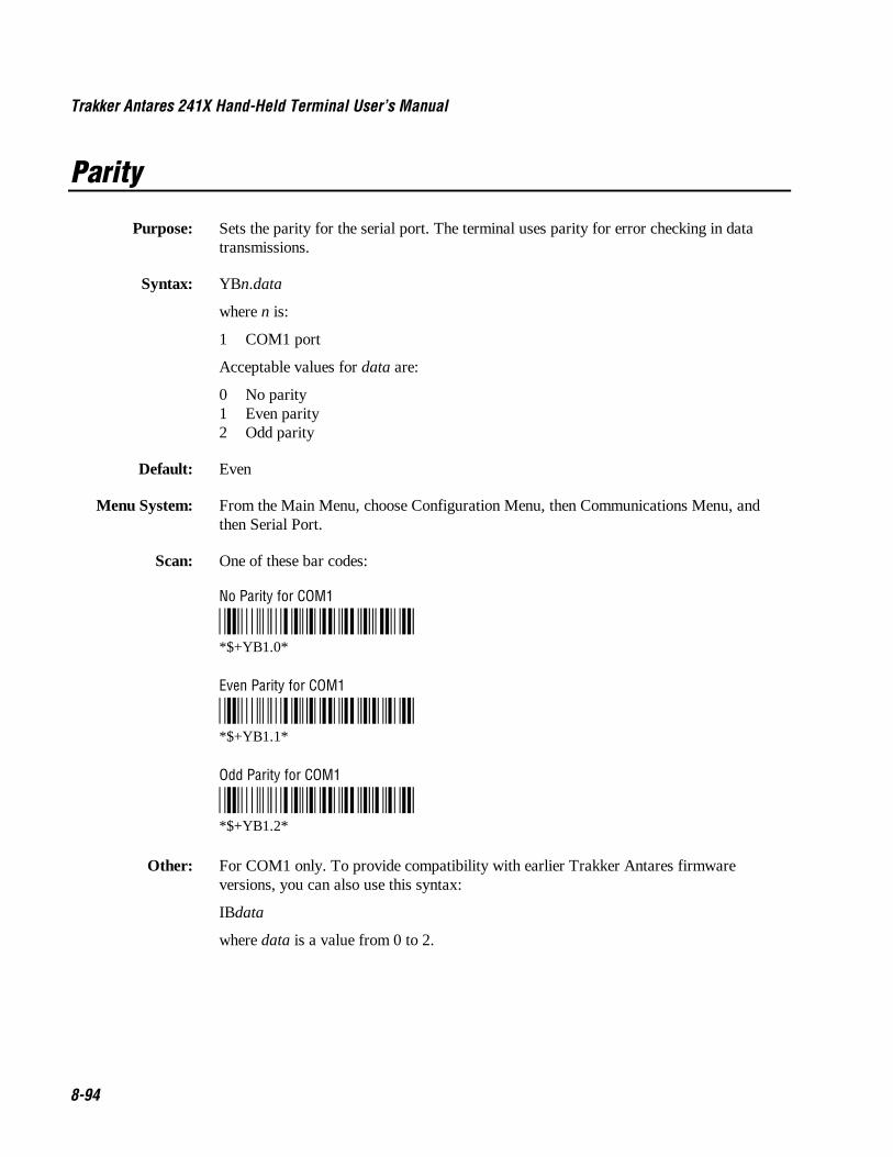
Trakker Antares 241X Hand-Held Terminal User’s Manual Co de 39 Nugget
8-94
Parity
Purpose: Sets the parity for the serial port. The terminal uses parity for error checking in datatransmissions.
Syntax: YBn.data
where n is:
1 COM1 port
Acceptable values for data are:
0 No parity1 Even parity2 Odd parity
Default: Even
Menu System: From the Main Menu, choose Configuration Menu, then Communications Menu, andthen Serial Port.
Scan: One of these bar codes:
No Parity for COM1
*$+YB1.0**$+YB1.0*
Even Parity for COM1
*$+YB1.1**$+YB1.1*
Odd Parity for COM1
*$+YB1.2**$+YB1.2*
Other: For COM1 only. To provide compatibility with earlier Trakker Antares firmwareversions, you can also use this syntax:
IBdata
where data is a value from 0 to 2.

Co de 39 Nugget Configuration Command Reference
8-95
8Plessey
Purpose: Enables or disables decoding of Plessey symbology. Plessey code is pulse-widthmodulated like most other bar codes. It includes a start character, data characters, aneight-bit cyclic check digit, a termination bar, and usually a reverse start character. Thecode is continuous and not self-checking. You need to configure two parameters forPlessey code: Start Code and Check Digit.
Syntax: CIdata
Acceptable values for data are:
00 Disabled10 Plessey with reverse start code30 Transmit check digit31 Discard check digit
Default: Disabled
Menu System: From the Main Menu, choose Configuration Menu, then Symbologies Menu, and thenPlessey.
Scan: To disable Plessey:
Disable Plessey
*$+CI00**$+CI00*
Or: To set Plessey, complete these steps:
1. Scan this bar code:
Plessey With Reverse Start Code
*$+CI10**$+CI10*
2. Scan one of these bar codes to transmit or retain the check digit:
Transmit Check Digit
*$+CI30**$+CI30*
Discard Check Digit
*$+CI31**$+CI31*

Trakker Antares 241X Hand-Held Terminal User’s Manual Co de 39 Nugget
8-96
Poll (Polling)
Purpose: Solicits or requests data from a polled device.
Note: Before you can enable Poll, you must configure the EOM and Handshakecommands.
Syntax: YRn.data
where n is:
1 COM1 port
Acceptable values for data are:
Disabled No pollingEnabled \x1C (hexadecimal value for FS)
Default: Disabled
Menu System: From the Main Menu, choose Configuration Menu, then Communications Menu, andthen Serial Port.
Scan: To disable poll, scan one of these bar codes:
Note: To scan these bar code labels, you must configure the terminal to use Code 39 inFull ASCII mode. For help, see “Code 39” earlier in this chapter.
Disable Poll for COM1
*/D/KYR1.**$+YR1.*
Enable Poll (Set to FS) for COM1
*/D/KYR1.%B**$+YR1.%B*
Other: For COM1 only. To provide compatibility with earlier Trakker Antares firmwareversions, you can also use this syntax:
HBdata
where data is disabled or enabled (set to FS).
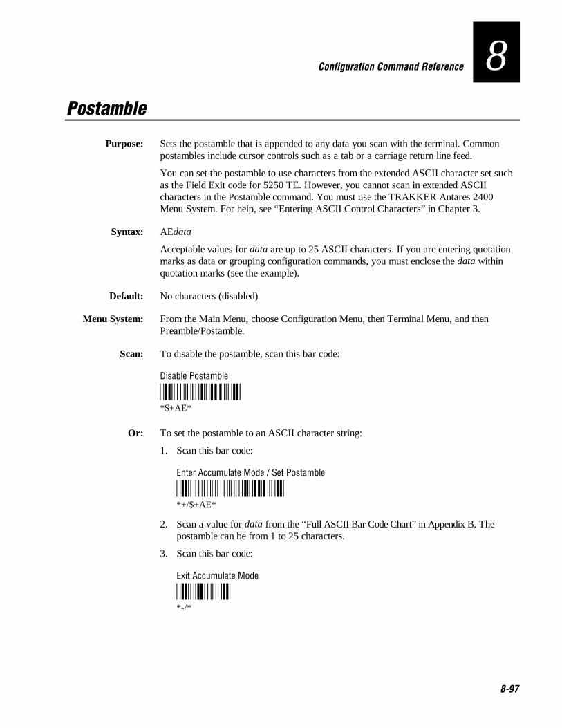
Co de 39 Nugget Configuration Command Reference
8-97
8Postamble
Purpose: Sets the postamble that is appended to any data you scan with the terminal. Commonpostambles include cursor controls such as a tab or a carriage return line feed.
You can set the postamble to use characters from the extended ASCII character set suchas the Field Exit code for 5250 TE. However, you cannot scan in extended ASCIIcharacters in the Postamble command. You must use the TRAKKER Antares 2400Menu System. For help, see “Entering ASCII Control Characters” in Chapter 3.
Syntax: AEdata
Acceptable values for data are up to 25 ASCII characters. If you are entering quotationmarks as data or grouping configuration commands, you must enclose the data withinquotation marks (see the example).
Default: No characters (disabled)
Menu System: From the Main Menu, choose Configuration Menu, then Terminal Menu, and thenPreamble/Postamble.
Scan: To disable the postamble, scan this bar code:
Disable Postamble
*$+AE**$+AE*
Or: To set the postamble to an ASCII character string:
1. Scan this bar code:
Enter Accumulate Mode / Set Postamble
*+/$+AE**+/$+AE*
2. Scan a value for data from the “Full ASCII Bar Code Chart” in Appendix B. Thepostamble can be from 1 to 25 characters.
3. Scan this bar code:
Exit Accumulate Mode
*-/**-/*

Trakker Antares 241X Hand-Held Terminal User’s Manual Co de 39 Nugget
8-98
Postamble (continued)
Example: You want to set a postamble that includes quotation marks. To scan a bar code label thatincludes quotation marks, you must configure the terminal to use Code 39 in Full ASCIImode. For help, see “Code 39” earlier in this chapter.
Enter the postamble by scanning this full ASCII bar code label:
Set Postamble to “B”
*/D/KAE/B/B/BB/B/B/B**$+AE"""B"""*
You must enclose the data within quotation marks and precede each quotation mark withanother quotation mark so that the quotation marks are not treated as the end of the data.

Co de 39 Nugget Configuration Command Reference
8-99
8Power Management
Purpose: (IEEE 802.11 DS radio parameter) Determines if power management is enabled for theradio. If you enable power management, the radio conserves power by sleeping betweenmessages. Enabling power management decreases the performance of the RF network,but it increases the life of battery-powered devices.
Syntax: LGdata
Acceptable values for data are:
0 Disabled1 Enabled
Default: Enabled
Menu System: From the Main Menu, choose Configuration Menu, then Communications Menu, andthen Radio.
Scan: One of these bar codes:
Disable Power Management
*$+LG0**$+LG0*
Enable Power Management
*$+LG1**$+LG1*

Trakker Antares 241X Hand-Held Terminal User’s Manual Co de 39 Nugget
8-100
Preamble
Purpose: Sets the preamble that precedes any data you scan with the terminal. Common preamblesinclude a data location number or an operator number.
You can set the preamble to use characters from the extended ASCII character set.However, you cannot scan in extended ASCII characters in the Preamble command. Youneed to use the TRAKKER Antares 2400 Menu System. For help, see “Entering ASCIIControl Characters” in Chapter 3.
Syntax: ADdata
Acceptable values for data are up to 25 ASCII characters. If you are entering quotationmarks as data or grouping configuration commands, you need to enclose the data withinquotation marks (see the example).
Default: No characters (disabled)
Menu System: From the Main Menu, choose Configuration Menu, then Terminal Menu, and thenPreamble/Postamble.
Scan: To disable the preamble, scan this bar code:
Disable Preamble
*$+AD**$+AD*
Or: To set the preamble to an ASCII character string:
1. Scan this bar code:
Enter Accumulate Mode / Set Preamble
*+/$+AD**+/$+AD*
2. Scan a value for data from the “Full ASCII Bar Code Chart” in Appendix B. Thepreamble can be from 1 to 25 characters.
3. Scan this bar code:
Exit Accumulate Mode
*-/**-/*

Co de 39 Nugget Configuration Command Reference
8-101
8Preamble (continued)
Example: You want to set a preamble that includes quotation marks. To scan a bar code label thatincludes quotation marks, you must configure the terminal to use Code 39 in Full ASCIImode. For help, see “Code 39” earlier in this chapter.
Enter the preamble by scanning this full ASCII bar code label:
Set Preamble to “B”
*/D/KAD/B/B/BB/B/B/B**$+AD"""B"""*
You must enclose the data within quotation marks and precede each quotation mark withanother quotation mark so that the quotation marks are not treated as the end of the data.

Trakker Antares 241X Hand-Held Terminal User’s Manual Co de 39 Nugget
8-102
RAM Drive Size
Purpose: Configures the size and use of the RAM drive. You can use the RAM drive (drive E) totemporarily store data and files. You can also disable the RAM drive and use theadditional 256K for application execution space or programmable (Malloc) memoryallocations.
After you set the RAM drive, you must save the configuration in flash memory and bootthe terminal for the change to take effect.
Syntax: FRdata
Acceptable values for data are:
0 Disabled, no RAM drive16-256 RAM drive size in kilobytes (K)
Default: Disabled, no RAM drive
Menu System: From the Main Menu, choose Configuration Menu, then Terminal Menu, and then RAMDrive.
Scan: To disable the RAM drive, scan this bar code:
Disable RAM Drive
*$+FR0**$+FR0*
Or: To set the RAM drive size:
1. Scan this bar code:
Enter Accumulate Mode / Set RAM Drive Size
*+/$+FR**+/$+FR*
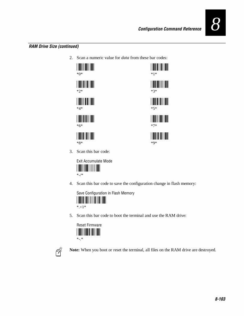
Co de 39 Nugget Configuration Command Reference
8-103
8RAM Drive Size (continued)
2. Scan a numeric value for data from these bar codes:
*0* *1**0* *1*
*2* *3**2* *3*
*4* *5**4* *5*
*6* *7**6* *7*
*8* *9**8* *9*
3. Scan this bar code:
Exit Accumulate Mode
*-/**-/*
4. Scan this bar code to save the configuration change in flash memory:
Save Configuration in Flash Memory
*.+1**.+1*
5. Scan this bar code to boot the terminal and use the RAM drive:
Reset Firmware
*-.**-.*
Note: When you boot or reset the terminal, all files on the RAM drive are destroyed.

Trakker Antares 241X Hand-Held Terminal User’s Manual Co de 39 Nugget
8-104
Receive All Multicast
Purpose: (IEEE 802.11 DS radio parameter) Determines if the 2415 needs to receive all multicastmessages. If you enable this parameter, the radio will stay awake to receive all multicastmessages that are forwarded by the access point. If you disable this parameter, the radiosleeps more often, thus conserving battery power.
Note: Before you set the reservation, you must set the Power Management command toenable.
Syntax: LIdata
Acceptable values for data are:
0 Disabled1 Enabled
Default: Enabled
Menu System: From the Main Menu, choose Configuration Menu, then Communications Menu, andthen Radio.
Scan: One of these bar codes:
Disable Receive All Multicast
*$+LI0**$+LI0*
Enable Receive All Multicast
*$+LI1**$+LI1*

Co de 39 Nugget Configuration Command Reference
8-105
8Reservation
Purpose: (IEEE 802.11 DS radio parameter) Specifies the maximum packet size that the 2415 cansend before it uses medium reservation (RTS/CTS). That is, packets that are greater thanor equal to this packet size use the medium reservation mechanism to help preventcollisions with packets from other devices.
Note: Before you set the reservation, you must set the Reservation Enable command toenable.
Syntax: LDdata
Acceptable values of data are from 0 to 2346.
Default: 500
Menu System: From the Main Menu, choose Configuration Menu, then Communications Menu, andthen Radio.
Scan: To set the default reservation, scan this bar code:
Default Reservation
*$+LD500**$+LD500
Or: To set the reservation:
1. Scan this bar code:
Enter Accumulate Mode / Set Reservation
*+/$+LD**+/$+LD*

Trakker Antares 241X Hand-Held Terminal User’s Manual Co de 39 Nugget
8-106
Reservation (continued)
2. Scan a numeric value for data from these bar codes:
*0* *1**0* *1*
*2* *3**2* *3*
*4* *5**4* *5*
*6* *7**6* *7*
*8* *9**8* *9*
3. Scan this bar code:
Exit Accumulate Mode
*-/**-/*

Co de 39 Nugget Configuration Command Reference
8-107
8Reservation Enable
Purpose: (IEEE 802.11 DS radio parameter) Determines if the 2415 uses medium reservation(RTS/CTS). You should enable this parameter when you expect that your network willhave hidden stations. When you enable this parameter, you also need to set theReservation command. You may want to disable this parameter to improve networkresponse time if the 2415 usually sends very small packets and the network does not haveany hidden stations.
Syntax: LCdata
Acceptable values for data are:
0 Disabled1 Enabled
Default: Enabled
Menu System: From the Main Menu, choose Configuration Menu, then Communications Menu, andthen Radio.
Scan: One of these bar codes:
Enable Reservation
*$+LC1**$+LC1*
Disable Reservation
*$+LC0**$+LC0*

Trakker Antares 241X Hand-Held Terminal User’s Manual Co de 39 Nugget
8-108
Resume Execution
Purpose: Defines the way in which the terminal resumes when you press : to turn on the terminal.If you set this parameter to resume execution not allowed and you press : to turn on theterminal, the terminal will boot and restart the application that was running when youturned off the terminal. If you set this parameter to resume execution allowed and press: to turn on the terminal, the terminal resumes exactly where it was when you turned offthe terminal.
Syntax: ERdata
Acceptable values for data are:
0 Not allowed1 Allowed
Default: Allowed
Menu System: From the Main Menu, choose Configuration Menu, then Terminal Menu, and then PowerManagement.
Scan: One of these bar codes:
Resume Execution Not Allowed
*$+ER0**$+ER0*
Resume Execution Allowed
*$+ER1**$+ER1*

Co de 39 Nugget Configuration Command Reference
8-109
8Roaming Flag
Purpose: (OpenAir radio parameter) Determines whether or not the 2415 can roam between accesspoints. All access points are master stations and each master has a unique channel. If youhave five access points in one domain, the 2415 will connect to one access point whenyou turn it on. This access point becomes the master station for the 2415. When you setthe roaming flag to “Not Allowed,” the 2415 will only communicate with the access pointto which it first connects. If you allow roaming, the 2415 can communicate with anyaccess point in the same domain.
Syntax: RRdata
Acceptable values for data are:
0 Allowed1 Not allowed
Default: Allowed
Menu System: From the Main Menu, choose Configuration Menu, then Communications Menu, andthen Radio.
Scan: One of these bar codes:
Roaming Allowed
*$+RR0**$+RR0*
Roaming Not Allowed
*$+RR1**$+RR1*

Trakker Antares 241X Hand-Held Terminal User’s Manual Co de 39 Nugget
8-110
Scan Ahead
Purpose: Enables or disables scan ahead. If you enable this parameter, you can scan a number oflabels that are held in a stack until the terminal can process the data. If you disable thisparameter, the terminal processes each label you scan before you can scan the next label.
Syntax: SDdata
Acceptable values for data are:
0 Disabled (scan one label at a time)1 Enabled (scan many labels at a time)
Default: Disabled
Menu System: From the Main Menu, choose Configuration Menu, then Terminal Menu, and thenScanner.
Scan: One of these bar codes:
Disable Scan Ahead
*$+SD0**$+SD0*
Enable Scan Ahead
*$+SD1**$+SD1*

Co de 39 Nugget Configuration Command Reference
8-111
8Scanner Mode
Purpose: Defines how the scanner operates when you press the Scan button or activate a cabledlaser scanner. There are two types of modes:
• In One-Shot mode, you must press the Scan button or activate the cabled laserscanner each time you want to scan a bar code. Once you scan a bar code, thescanner turns off.
• In Automatic (Auto-trigger) mode, you press the Scan button once or activate thecabled laser scanner once to scan a series of bar codes. When you release the buttonor trigger, the scanner turns off. To scan the same bar code more than once, you mustrelease the Scan button or trigger, or scan a different bar code before attempting asecond scan.
Syntax: SBdata
Acceptable values for data are:
0 One-Shot mode1 Automatic mode
Default: One-Shot mode
Menu System: From the Main Menu, choose Configuration Menu, then Terminal Menu, and thenScanner.
Scan: One of these bar codes:
Enable One-Shot Mode
*$+SB0**$+SB0*
Enable Automatic Mode
*$+SB1**$+SB1*
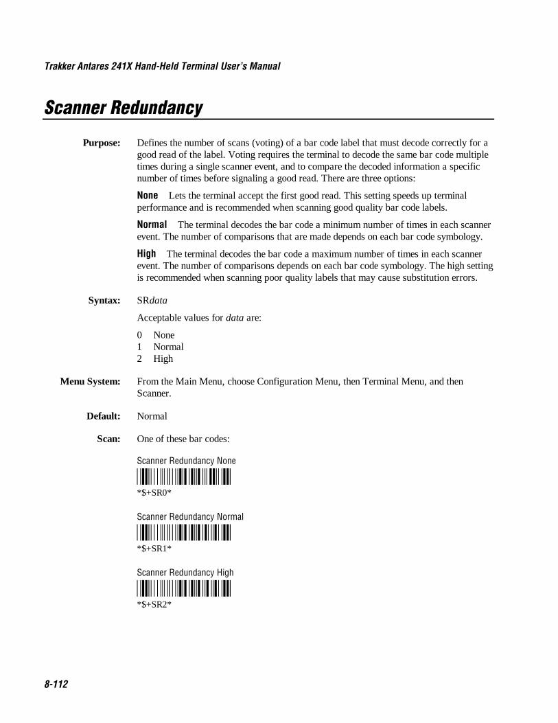
Trakker Antares 241X Hand-Held Terminal User’s Manual Co de 39 Nugget
8-112
Scanner Redundancy
Purpose: Defines the number of scans (voting) of a bar code label that must decode correctly for agood read of the label. Voting requires the terminal to decode the same bar code multipletimes during a single scanner event, and to compare the decoded information a specificnumber of times before signaling a good read. There are three options:
None Lets the terminal accept the first good read. This setting speeds up terminalperformance and is recommended when scanning good quality bar code labels.
Normal The terminal decodes the bar code a minimum number of times in each scannerevent. The number of comparisons that are made depends on each bar code symbology.
High The terminal decodes the bar code a maximum number of times in each scannerevent. The number of comparisons depends on each bar code symbology. The high settingis recommended when scanning poor quality labels that may cause substitution errors.
Syntax: SRdata
Acceptable values for data are:
0 None1 Normal2 High
Menu System: From the Main Menu, choose Configuration Menu, then Terminal Menu, and thenScanner.
Default: Normal
Scan: One of these bar codes:
Scanner Redundancy None
*$+SR0**$+SR0*
Scanner Redundancy Normal
*$+SR1**$+SR1*
Scanner Redundancy High
*$+SR2**$+SR2*

Co de 39 Nugget Configuration Command Reference
8-113
8Scanner Selection
Purpose: Identifies the type of scanner you have connected to the terminal. The terminal canoptimize the scanning performance by using the scanner you define in this command.When you select a specific scanner, other scanners may not function properly. Yourterminal may not work if you connect an incompatible scanner.
Syntax: SSdata
Acceptable values for data are:
0 All compatible scanners (including wands)6 155x laser scanners11 241X scanner, including normal, long range, high density, or high visibility
(long-range or high-visibility with no aim)12 Long-range, high-density, or high-visibility scanner with short aim13 Long-range, high-density, or high-visibility scanner with long aim
Default: All compatible scanners
Menu System: From the Main Menu, choose Configuration Menu, then Terminal Menu, and thenScanner.
Scan: One of these bar codes:
All Compatible Scanners 155X Laser Scanners
*$+SS0* *$+SS6**$+SS0* *$+SS6*
241X Scanner (No Aim) 241X Scanner (Short Aim)
*$+SS11* *$+SS12**$+SS11* *$+SS12*
241X Scanner (Long Aim)
*$+SS13**$+SS13*

Trakker Antares 241X Hand-Held Terminal User’s Manual Co de 39 Nugget
8-114
Scanner Timeout
Purpose: Defines the maximum length of time the scanner stays after you press the Scan button oractivate a cabled laser scanner.
Syntax: SAdata
Acceptable values for data are:
0 Disabled1-60 Shutoff time in seconds
Default: Disabled (no timeout)
Menu System: From the Main Menu, choose Configuration Menu, then Terminal Menu, and thenScanner.
Scan: To disable the scanner timeout, scan this bar code:
Disable Scanner Timeout
*$+SA0**$+SA0*
Or: To set the scanner timeout:
1. Scan this bar code:
Enter Accumulate Mode / Set Scanner Timeout
*+/$+SA**+/$+SA*

Co de 39 Nugget Configuration Command Reference
8-115
8Scanner Timeout (continued)
2. Scan a numeric value for data from these bar codes:
*0* *1**0* *1*
*2* *3**2* *3*
*4* *5**4* *5*
*6* *7**6* *7*
*8* *9**8* *9*
3. Scan this bar code:
Exit Accumulate Mode
*-/**-/*

Trakker Antares 241X Hand-Held Terminal User’s Manual Co de 39 Nugget
8-116
Scanner Trigger
Purpose: Scanner trigger lets you set level triggering or edge triggering.
• With level triggering, you activate the scanner and the laser turns on and stays onuntil you release the button or the trigger on a cabled scanner.
• In edge triggering, you activate the scanner and the laser turns on and stays on. Whenyou activate the scanner a second time, the laser turns off. Simply releasing thebutton or the trigger does not turn the laser off. If the laser is left on, the scannertimeout turns the laser off.
Syntax: SCdata
Acceptable values for data are:
0 Level triggering1 Edge triggering
Default: Level triggering
Menu System: From the Main Menu, choose Configuration Menu, then Terminal Menu, and thenScanner.
Scan: One of these bar codes:
Enable Level Triggering
*$+SC0**$+SC0*
Enable Edge Triggering
*$+SC1**$+SC1*
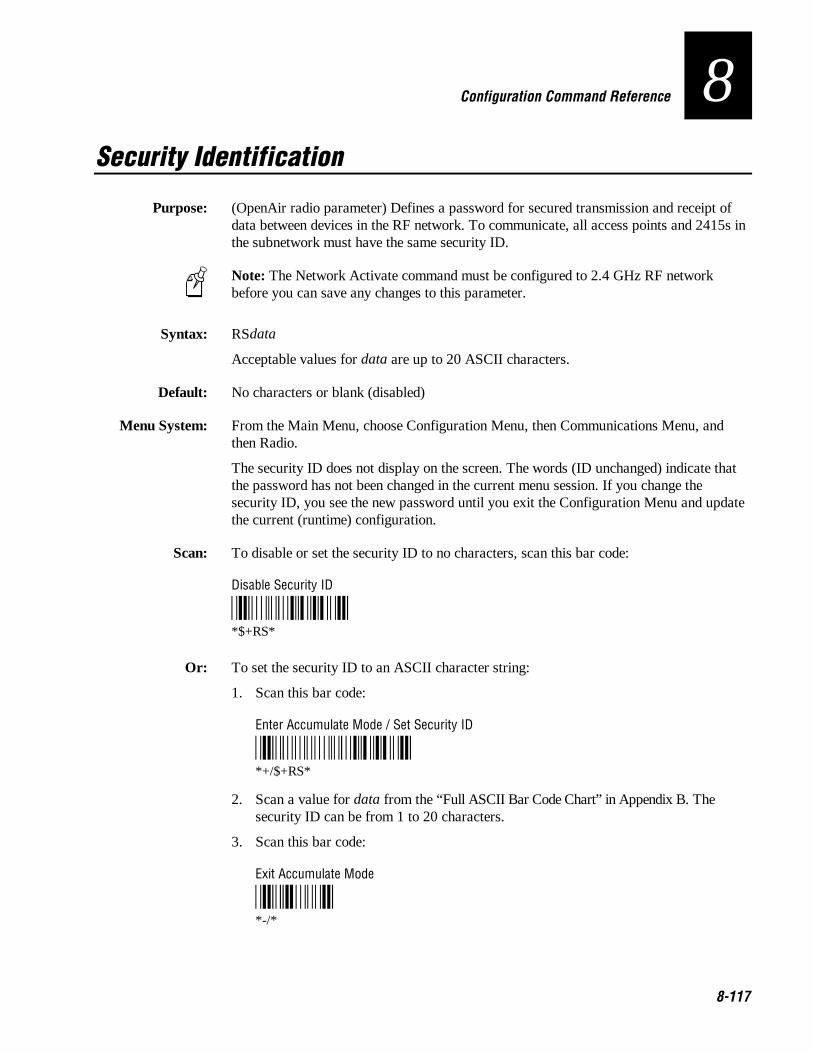
Co de 39 Nugget Configuration Command Reference
8-117
8Security Identification
Purpose: (OpenAir radio parameter) Defines a password for secured transmission and receipt ofdata between devices in the RF network. To communicate, all access points and 2415s inthe subnetwork must have the same security ID.
Note: The Network Activate command must be configured to 2.4 GHz RF networkbefore you can save any changes to this parameter.
Syntax: RSdata
Acceptable values for data are up to 20 ASCII characters.
Default: No characters or blank (disabled)
Menu System: From the Main Menu, choose Configuration Menu, then Communications Menu, andthen Radio.
The security ID does not display on the screen. The words (ID unchanged) indicate thatthe password has not been changed in the current menu session. If you change thesecurity ID, you see the new password until you exit the Configuration Menu and updatethe current (runtime) configuration.
Scan: To disable or set the security ID to no characters, scan this bar code:
Disable Security ID
*$+RS**$+RS*
Or: To set the security ID to an ASCII character string:
1. Scan this bar code:
Enter Accumulate Mode / Set Security ID
*+/$+RS**+/$+RS*
2. Scan a value for data from the “Full ASCII Bar Code Chart” in Appendix B. Thesecurity ID can be from 1 to 20 characters.
3. Scan this bar code:
Exit Accumulate Mode
*-/**-/*
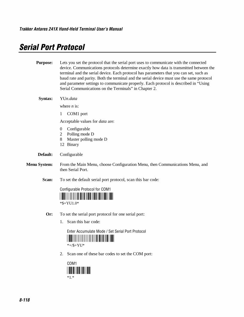
Trakker Antares 241X Hand-Held Terminal User’s Manual Co de 39 Nugget
8-118
Serial Port Protocol
Purpose: Lets you set the protocol that the serial port uses to communicate with the connecteddevice. Communications protocols determine exactly how data is transmitted between theterminal and the serial device. Each protocol has parameters that you can set, such asbaud rate and parity. Both the terminal and the serial device must use the same protocoland parameter settings to communicate properly. Each protocol is described in “UsingSerial Communications on the Terminals” in Chapter 2.
Syntax: YUn.data
where n is:
1 COM1 port
Acceptable values for data are:
0 Configurable2 Polling mode D8 Master polling mode D12 Binary
Default: Configurable
Menu System: From the Main Menu, choose Configuration Menu, then Communications Menu, andthen Serial Port.
Scan: To set the default serial port protocol, scan this bar code:
Configurable Protocol for COM1
*$+YU1.0**$+YU1.0*
Or: To set the serial port protocol for one serial port:
1. Scan this bar code:
Enter Accumulate Mode / Set Serial Port Protocol
*+/$+YU**+/$+YU*
2. Scan one of these bar codes to set the COM port:
COM1
*1.**1.*

Co de 39 Nugget Configuration Command Reference
8-119
8Serial Port Protocol (continued)
3. Scan the protocol setting:
Configurable Polling Mode D
*0* *2**0* *2*
Master Polling Binary
*8* *12**8* *12*
4. Scan this bar code:
Exit Accumulate Mode
*-/**-/*

Trakker Antares 241X Hand-Held Terminal User’s Manual Co de 39 Nugget
8-120
Start of Message (SOM)
Purpose: SOM is the first character in a message sent to or received from the host computerthrough the terminal’s serial port. SOM cannot equal the same value that is set for EOM.You cannot set SOM to any of these values:
• AFF (ACK) • REQ (ENQ)• DLE • SEL• NEG (NAK) • XOFF• Poll • XON• RES (EOT)
Note: Before you can enable SOM, you must enable the EOM command.
Syntax: YYn.data
where n is:
1 COM1 port
An acceptable value for data is any ASCII character.
Default: \x02 (hexadecimal value for STX)
Menu System: From the Main Menu, choose Configuration Menu, then Communications Menu, andthen Serial Port.
Scan: To set the default SOM, scan this bar code:
Note: To scan these bar code labels, you must configure the terminal to use Code 39 inFull ASCII mode. For help, see “Code 39” earlier in this chapter.
Default SOM for COM1
*/D/KYY1.$B**$+YY1.$B *
Or: To disable SOM, scan this bar code:
Disable SOM for COM1
*$+YY1.**$+YY1.*
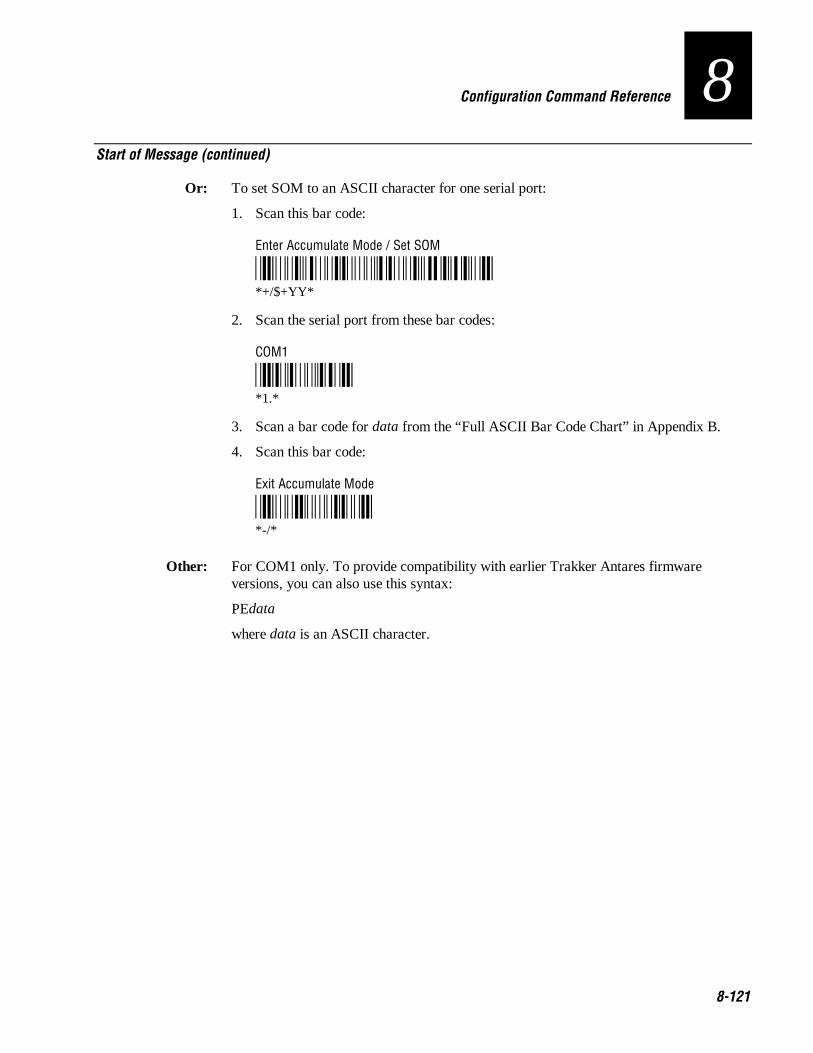
Co de 39 Nugget Configuration Command Reference
8-121
8Start of Message (continued)
Or: To set SOM to an ASCII character for one serial port:
1. Scan this bar code:
Enter Accumulate Mode / Set SOM
*/K/O/D/KYY**+/$+YY*
2. Scan the serial port from these bar codes:
COM1
*1/N**1.*
3. Scan a bar code for data from the “Full ASCII Bar Code Chart” in Appendix B.
4. Scan this bar code:
Exit Accumulate Mode
*/M/O**-/*
Other: For COM1 only. To provide compatibility with earlier Trakker Antares firmwareversions, you can also use this syntax:
PEdata
where data is an ASCII character.
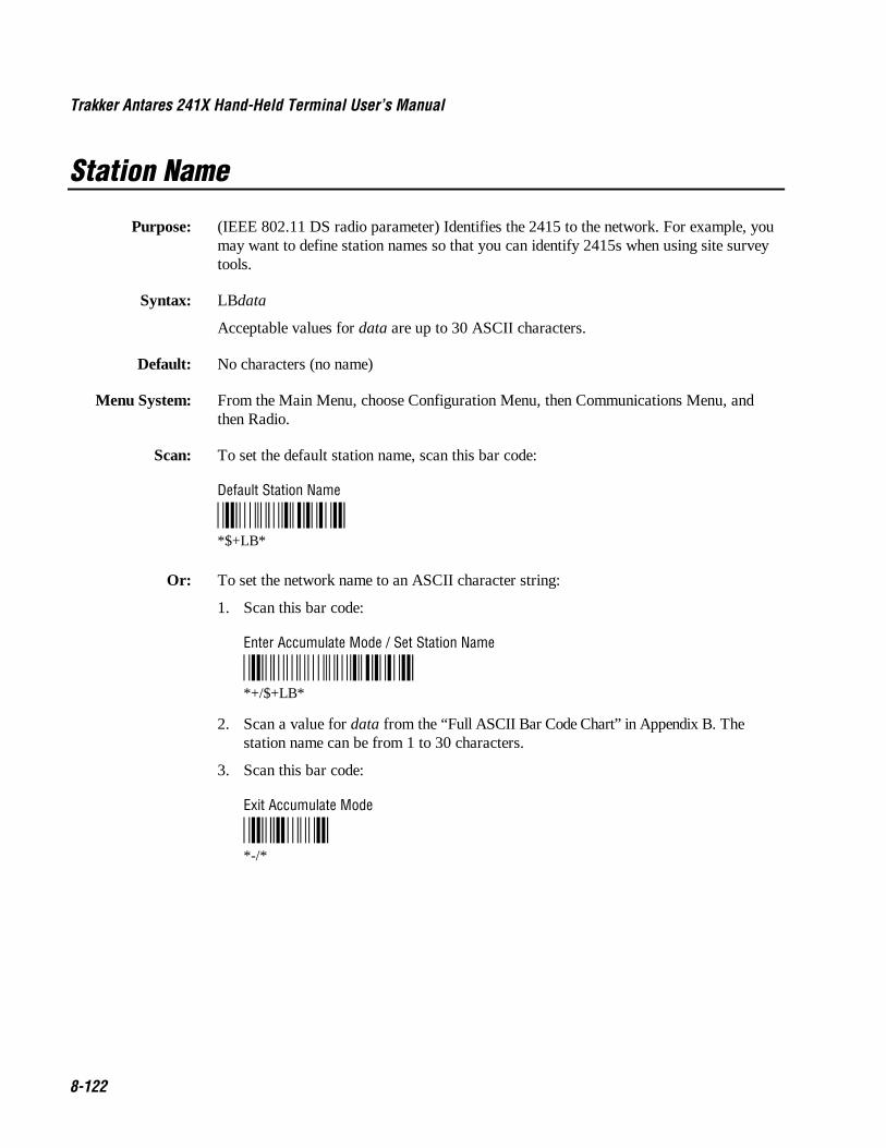
Trakker Antares 241X Hand-Held Terminal User’s Manual Co de 39 Nugget
8-122
Station Name
Purpose: (IEEE 802.11 DS radio parameter) Identifies the 2415 to the network. For example, youmay want to define station names so that you can identify 2415s when using site surveytools.
Syntax: LBdata
Acceptable values for data are up to 30 ASCII characters.
Default: No characters (no name)
Menu System: From the Main Menu, choose Configuration Menu, then Communications Menu, andthen Radio.
Scan: To set the default station name, scan this bar code:
Default Station Name
*$+LB**$+LB*
Or: To set the network name to an ASCII character string:
1. Scan this bar code:
Enter Accumulate Mode / Set Station Name
*+/$+LB**+/$+LB*
2. Scan a value for data from the “Full ASCII Bar Code Chart” in Appendix B. Thestation name can be from 1 to 30 characters.
3. Scan this bar code:
Exit Accumulate Mode
*-/**-/*

Co de 39 Nugget Configuration Command Reference
8-123
8Stop Bits
Purpose: Sets the number of stop bits on the serial port.
Syntax: YCn.data
where n is:
1 COM1 port
Acceptable values for data are:
1 1 stop bit2 2 stop bits
Default: 1
Menu System: From the Main Menu, choose Configuration Menu, then Communications Menu, andthen Serial Port.
Scan: One of these bar codes:
1 Stop Bit for COM1 2 Stop Bits for COM1
*$+YC1.1* *$+YC1.2**$+YC1.1* *$+YC1.2*
Other: For COM1 only. To provide compatibility with earlier Trakker Antares firmwareversions, you can also use this syntax:
ICdata
where data is a value of 1 or 2.
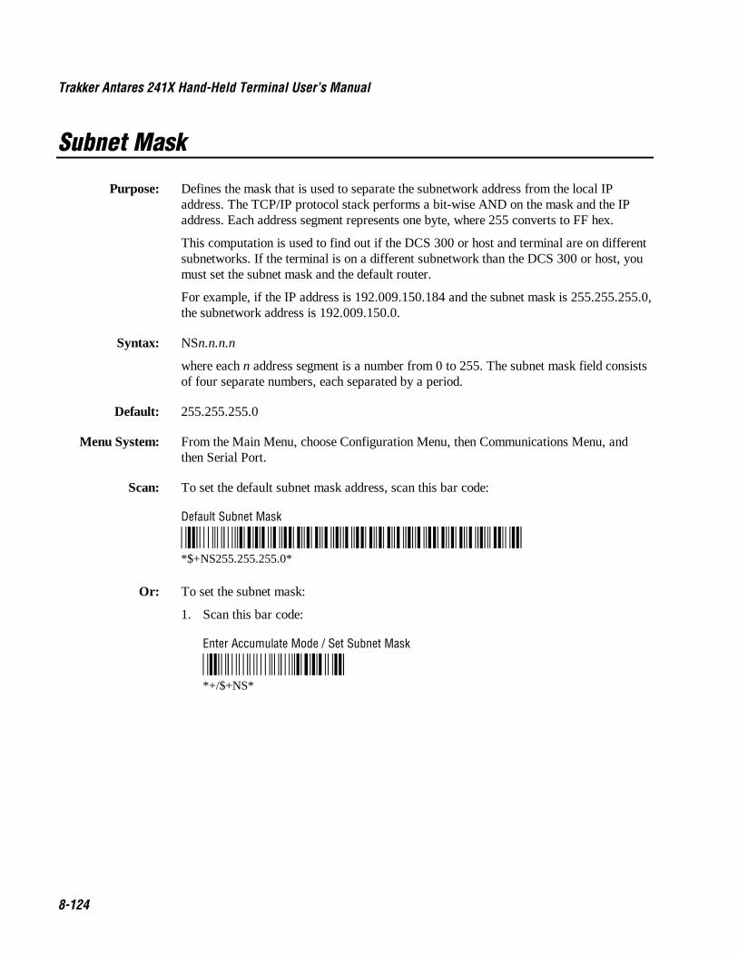
Trakker Antares 241X Hand-Held Terminal User’s Manual Co de 39 Nugget
8-124
Subnet Mask
Purpose: Defines the mask that is used to separate the subnetwork address from the local IPaddress. The TCP/IP protocol stack performs a bit-wise AND on the mask and the IPaddress. Each address segment represents one byte, where 255 converts to FF hex.
This computation is used to find out if the DCS 300 or host and terminal are on differentsubnetworks. If the terminal is on a different subnetwork than the DCS 300 or host, youmust set the subnet mask and the default router.
For example, if the IP address is 192.009.150.184 and the subnet mask is 255.255.255.0,the subnetwork address is 192.009.150.0.
Syntax: NSn.n.n.n
where each n address segment is a number from 0 to 255. The subnet mask field consistsof four separate numbers, each separated by a period.
Default: 255.255.255.0
Menu System: From the Main Menu, choose Configuration Menu, then Communications Menu, andthen Serial Port.
Scan: To set the default subnet mask address, scan this bar code:
Default Subnet Mask
*$+NS255.255.255.0**$+NS255.255.255.0*
Or: To set the subnet mask:
1. Scan this bar code:
Enter Accumulate Mode / Set Subnet Mask
*+/$+NS**+/$+NS*

Co de 39 Nugget Configuration Command Reference
8-125
8Subnet Mask (continued)
2. Scan a numeric value from 0 to 255 to set an n field of the subnet mask address fromthese bar codes.
*0* *1**0* *1*
*2* *3**2* *3*
*4* *5**4* *5*
*6* *7**6* *7*
*8* *9**8* *9*
3. Scan this bar code:
. (Period)
*.**.*
4. Repeat Steps 2 and 3 to set the next three numbers in the subnet mask address field.After you scan the last address segment, go to Step 5. Do not scan the period afterthe last address segment.
5. Scan this bar code:
Exit Accumulate Mode
*-/**-/*

Trakker Antares 241X Hand-Held Terminal User’s Manual Co de 39 Nugget
8-126
Suspend/Resume Control
Purpose: Controls the operation of the : key (suspend/resume). When the : key is enabled, youcan turn the terminal on and off. When the : key is disabled, you cannot turn off theterminal.
Syntax: EFdata
Acceptable values for data are:
0 Enabled1 Disabled
Default: Enabled
Menu System: Not supported
Scan: One of these bar codes:
Enable : Key
*$+EF0**$+EF0*
Disable : Key
*$+EF1**$+EF1*

Co de 39 Nugget Configuration Command Reference
8-127
8TCP Maximum Retries
Purpose: Defines the maximum number of times that TCP will attempt to transmit data beforegiving up and terminating the TCP connection.
Syntax: NJdata
Acceptable values for data are any number from 5 to 50.
Default: 12
Menu System: Not supported
Scan: To set the default TCP maximum retries, scan this bar code:
Default TCP Maximum Retries
*$+NJ12**$+NJ12*
Or: To set the TCP maximum retries:
1. Scan this bar code:
Enter Accumulate Mode / Set TCP Maximum Retries
*+/$+NJ**+/$+NJ*
2. Scan a numeric value for data from these bar codes:
*0* *1**0* *1*
*2* *3**2* *3*
*4* *5**4* *5*
*6* *7**6* *7*
*8* *9**8* *9*
Trakker Antares 241X Hand-Held Terminal User’s Manual Co de 39 Nugget
8-128
TCP Maximum Retries (continued)
3. Scan this bar code:
Exit Accumulate Mode
*-/**-/*

Co de 39 Nugget Configuration Command Reference
8-129
8TCP/IP Maximum Transmit Timeout
Purpose: Defines the maximum timeout that TCP will allow between retries of a transmission in aTCP/IP direct connect network before it gives up. Intermec has determined that theoptimum setting is 20 seconds.
Syntax: NHdata
Acceptable values for data are:
0 No timeout1-128 Transmit timeout in seconds
Default: 20 seconds
Menu System: From the Main Menu, choose Configuration Menu, then Communications Menu, andthen Advanced Network.
Scan: To set the default TCP/IP Maximum Transmit Timeout, scan this bar code:
Default TCP/IP Maximum Transmit Timeout
*$+NH20**$+NH20*
Or: To set the TCP/IP maximum transmit timeout:
1. Scan this bar code:
Enter Accumulate Mode / Set TCP/IP Maximum Transmit Timeout
*+/$+NH**+/$+NH*

Trakker Antares 241X Hand-Held Terminal User’s Manual Co de 39 Nugget
8-130
TCP Maximum Transmit Timeout (continued)
2. Scan a numeric value for data from these bar codes:
*0* *1**0* *1*
*2* *3**2* *3*
*4* *5**4* *5*
*6* *7**6* *7*
*8* *9**8* *9*
3. Scan this bar code:
Exit Accumulate Mode
*-/**-/*

Co de 39 Nugget Configuration Command Reference
8-131
8Terminal IP Address
Purpose: Defines the IP address that is assigned to the 2415 in your network. This IP address mustmatch the address that is set for this terminal on the DCS 300 or host computer.
Syntax: NDn.n.n.n
where each n address segment is a number from 0 to 255. The terminal IP address fieldconsists of four separate numbers, each separated by a period.
Note: The RF network cannot be activated if the first address segment in the IP addressis set to 0, 127, or a number greater than 223.
Default: 0.0.0.0
Menu System: From the Main Menu, choose Configuration Menu, then Communications Menu, andthen Primary Network.
Scan: To set the default terminal IP address, scan this bar code:
Default Terminal IP Address
*$+ND0.0.0.0**$+ND0.0.0.0*
Or: To set the terminal IP address:
1. Scan this bar code:
Enter Accumulate Mode / Set Terminal IP Address
*+/$+ND**+/$+ND*

Trakker Antares 241X Hand-Held Terminal User’s Manual Co de 39 Nugget
8-132
Terminal IP Address (continued)
2. Scan a numeric value from 0 to 255 to set an n field of the terminal IP address fromthese bar codes.
*0* *1**0* *1*
*2* *3**2* *3*
*4* *5**4* *5*
*6* *7**6* *7*
*8* *9**8* *9*
3. Scan this bar code:
. (Period)
*.**.*
4. Repeat Steps 2 and 3 to set the next three numbers in the terminal IP address field.After you scan the last address segment, go to Step 5. Do not scan the period afterthe last address segment.
5. Scan this bar code:
Exit Accumulate Mode
*-/**-/*

Co de 39 Nugget Configuration Command Reference
8-133
8Time and Date
Purpose: Sets the time and date on the terminal.
Syntax: DBdata
Acceptable values for data are 12 digits corresponding to:
yy 00-99 Yearmm 01-12 Month of the yeardd 01-31 Day of the monthhh 00-23 Hourmm 00-59 Minutesss 00-59 Seconds
Year values (yy) from 00 to 95 are interpreted as 2000 through 2095. Year values from96 to 99 are interpreted as 1996 through 1999.
Default: 960101120000
Menu System: From the Main Menu, choose System Menu.
Scan: To set the time and date:
1. Scan this bar code:
Enter Accumulate Mode / Set Time and Date
*+/$+DB**+/$+DB*
2. Scan a numeric value for each digit from these bar codes:
*0* *1**0* *1*
*2* *3**2* *3*
*4* *5**4* *5*
*6* *7**6* *7*
*8* *9**8* *9*
Trakker Antares 241X Hand-Held Terminal User’s Manual Co de 39 Nugget
8-134
Time and Date (continued)
3. Scan this bar code:
Exit Accumulate Mode
*-/**-/*

Co de 39 Nugget Configuration Command Reference
8-135
8Time in Seconds
Purpose: If you enable the Append Time command, you can enable the Time in Seconds commandto append the seconds to each bar code label that is scanned on the terminal. To appendthe time in only hours and minutes, disable the Time in Seconds command.
Syntax: DAdata
Acceptable values for data are:
0 Disabled1 Enabled
Default: Disabled
Menu System: From the Main Menu, choose Configuration Menu, then Terminal Menu, and thenAppend Time.
Scan: One of these bar codes:
Disable Time in Seconds
*$+DA0**$+DA0*
Enable Time in Seconds
*$+DA1**$+DA1*
Trakker Antares 241X Hand-Held Terminal User’s Manual Co de 39 Nugget
8-136
Timeout Delay
Purpose: If handshaking is enabled, the terminal expects a response to each message that is sent tothe host through the serial port. The timeout delay is the amount of time the terminalwaits to receive a response. When the timeout expires, the terminal tries sending themessage again. If no response is received after the terminal tries to send the messagethree times, a timeout error occurs. In polling mode D, the terminal sends another pollsequence when it resends the message.
Note: Before you can enable Timeout Delay, you must configure the EOM andHandshake commands.
Syntax: YEn.data
where n is:
1 COM1 port
Acceptable values for data are:
0 5 ms1 100 ms2 500 ms3 2 sec4 10 sec5 20 sec6 40 sec7 60 sec
Default: 10 seconds
Menu System: From the Main Menu, choose Configuration Menu, then Communications Menu, andthen Serial Port.
Scan: To set the default timeout delay, scan this bar code:
Timeout Delay 10 sec for COM1
*$+YE1.4**$+YE1.4*

Co de 39 Nugget Configuration Command Reference
8-137
8Timeout Delay (continued)
Or: To set the timeout delay for one serial port:
1. Scan this bar code:
Enter Accumulate Mode / Set Timeout Delay
*+/$+YE**+/$+YE*
2. Scan the serial port from these bar codes:
COM1
*1.**1.*
3. Scan the timeout delay from these bar codes:
Timeout Delay 5 ms Timeout Delay 100 ms
*0* *1**0* *1*
Timeout Delay 500 ms Timeout Delay 2 sec
*2* *3**2* *3*
Timeout Delay 10 sec Timeout Delay 20 sec
*4* *5**4* *5*
Timeout Delay 40 sec Timeout Delay 60 sec
*6* *7**6* *7*
4. Scan this bar code:
Exit Accumulate Mode
*-/**-/*
Other: For COM1 only. To provide compatibility with earlier Trakker Antares firmwareversions, you can also use this syntax:
IEdata
where data is a value from 0 to 7.

Trakker Antares 241X Hand-Held Terminal User’s Manual Co de 39 Nugget
8-138
Transmit Mode
Purpose: (OpenAir radio parameter) Defines the transmit mode that the 2415 radio uses. There arethree modes:
BFSK Binary Frequency Shift Key. A broadcasting method the radio uses thatlengthens the range, but halves the throughput. This method is switched when the RFprotocol on the terminal determines that communications are degrading.
QFSK Quad Frequency Shift Key. A broadcasting method the radio uses that shortensthe range, but doubles the throughput. QFSK is the method used under standard radioconditions.
Auto The terminal radio automatically switches modes between BFSK and QFSK asneeded.
Note: Even if you set this configuration command, the 2415 radio will reset theparameter as needed to maximize the broadcasting range and throughput.
Syntax: RTdata
Acceptable values for data are:
0 BFSK (Binary Frequency Shift Key)1 QFSK (Quad Frequency Shift Key)3 Auto
Default: BFSK
Menu System: From the Main Menu, choose Configuration Menu, then Communications Menu, andthen Radio.
Scan: One of these bar codes:
Set Transmit Mode to BFSK
*$+RT0**$+RT0*
Set Transmit Mode to QFSK
*$+RT1**$+RT1*
Set Transmit Mode to Auto
*$+RT3**$+RT3*

Co de 39 Nugget Configuration Command Reference
8-139
8Transmit Rate
Purpose: (IEEE 802.11 DS radio parameter) Sets the bit rate for data transmissions. The slowertransmit rate provides a better range. You should configure the terminals that are on theperimeter of the access point coverage area to the slower transmit rate. The fastertransmit rate provides better throughput. You should configure most of the terminals tothe faster transmit range.
Note: If the 21XX Universal Access Points are set to 2 Mbit/s with auto fallback, the2415s can transmit at any bit rate. If the 21XX UAPs are not set to this bit rate, thetransmit rate that is set on the 2415s must match the transmit rate of the 21XX UAPs.
Syntax: LEdata
Acceptable values for data are:
0 1 Mbit/s1 2 Mbit/s2 2 Mbit/s with auto fallback
Default: 2 Mbit/s with auto fallback
Menu System: From the Main Menu, choose Configuration Menu, then Communications Menu, andthen Radio.
Scan: One of these bar codes:
Set Transmit Rate to 1 Mbit/s
*$+LE0**$+LE0*
Set Transmit Rate to 2 Mbit/s
*$+LE1**$+LE1*
Set Transmit Rate to 2 Mbit/s With Auto Fallback
*$+LE2**$+LE2*

Trakker Antares 241X Hand-Held Terminal User’s Manual Co de 39 Nugget
8-140
UPC/EAN
Purpose: Enables or disables the decoding of Universal Product Code (UPC)/European ArticleNumbering (EAN) symbology. UPC/EAN are fixed length, numeric, continuoussymbologies that use four element widths. A terminal that is configured to decode EANbar codes can decode UPC, but the reverse is not true. UPC code is a subset of EANcode.
To define the UPC/EAN symbology, you set up to seven digits. The supplemental portionof a UPC or EAN label is a weak symbology and can be missed by the scanner forseveral reasons. In situations where supplementals are known to be present, reading justthe main symbol can be prevented until a valid supplemental is found. When using a laserscanner, performance degradation is not noticeable.
The fifth, sixth, and seventh digits are optional. To set the sixth digit, you must set thefifth digit. To set the seventh digit, you must set all seven digits.
Syntax: CEdata
where data must be 4 to 7 digits selected from this list:
First digit: 0 UPC-A/EAN-13 disabled1 UPC-A/EAN-13 enabled2 UPC-A only enabled
Second digit: 0 UPC-E disabled1 UPC-E enabled
Third digit: 0 EAN-8 disabled1 EAN-8 enabled
Fourth digit: 0 Supplementals not allowed1 Supplementals allowed2 Supplementals required3 Two-digit supplementals required4 Five-digit supplementals required
Fifth digit: 0 Discard check digit1 Transmit check digit
Sixth digit: 0 Discard number system digit1 Transmit number system digit
Seventh digit: 0 Discard the leading zero for UPC-A1 Retain the leading zero for UPC-A
Default: 1111111
First digit: UPC-A/EAN-13 enabledSecond digit: UPC-E enabledThird digit: EAN-8 enabled

Co de 39 Nugget Configuration Command Reference
8-141
8UPC/EAN (continued)
Fourth digit: Supplementals allowedFifth digit: Transmit check digitSixth digit: Transmit number system digitSeventh digit: Retain leading zero for UPC-A
Menu System: From the Main Menu, choose Configuration Menu, then Symbologies Menu, and thenUPC/EAN.
Scan: To disable UPC/EAN, scan this bar code:
Disable UPC/EAN
*$+CE0000000**$+CE0000000*
Or: To enable UPC/EAN:
1. Scan this bar code:
Enter Accumulate Mode / Enable UPC/EAN
*+/$+CE**+/$+CE*
2. Scan one of these bar codes to set the first digit:
Disable UPC/EAN-13 Enable UPC/EAN-13
*0* *1**0* *1*
Enable UPC-A Only
*2**2*
3. Scan one of these bar codes to set the second digit:
Disable UPC-E Enable UPC-E
*0* *1**0* *1*
4. Scan one of these bar codes to set the third digit:
Disable EAN-8 Enable EAN-8
*0* *1**0* *1*

Trakker Antares 241X Hand-Held Terminal User’s Manual Co de 39 Nugget
8-142
UPC/EAN (continued)
5. Scan one of these bar codes to set the fourth digit:
Supplementals Not Allowed Supplementals Allowed
*0* *1**0* *1*
Supplementals Required Two-Digit Supplementals Required
*2* *3**2* *3*
Five-Digit Supplementals Required
*4**4*
6. (Optional) Scan one of these bar codes to set the fifth digit:
Discard Check Digit Transmit Check Digit
*0* *1**0* *1*
7. (Optional) Scan one of these bar codes to set the sixth digit:
Discard Number System Digit Transmit Number System Digit
*0* *1**0* *1*
Note: If you discard the number system digit, one leading digit is discarded fromUPC-A, UPC-E, and EAN-8, and two leading digits are discarded from EAN-13.
8. (Optional) Scan one of these bar codes to set the seventh digit:
Discard Leading Zero for UPC-A Transmit Leading Zero for UPC-A
*0* *1**0* *1*
Note: This option applies only when you enable UPC-A/EAN-13.
9. Scan this bar code:
Exit Accumulate Mode
*-/**-/*
Co de 39 Nugget Configuration Command Reference
8-143
8Wakeup On Broadcast
Purpose: (OpenAir radio parameter) Determines if the 2415 can receive broadcast messages sentfrom the network. If the wakeup on broadcast is enabled, the 2415 radio will turn on toreceive broadcast messages. If this command is disabled, the terminal radio will ignorebroadcast messages.
Power Management Tip: If your network has many broadcast messages, you may wantto disable the wakeup on broadcast command to preserve the battery pack power.
Syntax: RBdata
Acceptable values for data are:
0 Disabled1 Enabled
Default: Disabled
Menu System: From the Main Menu, choose Configuration Menu, then Communications Menu, andthen Radio.
Scan: One of these bar codes:
Disable Wakeup On Broadcast
*$+RB0**$+RB0*
Enable Wakeup On Broadcast
*$+RB1**$+RB1*

TRAKKER Antares 241X Hand-Held Terminal User’s Manual Co de 39 Nugget
8-144

Specifications and Other Helpful Information
A

A-2
Co de 39 Nugget Specifications and Other Helpful Information
A-3
AThis appendix provides the physical and environmental specifications for theterminals. It also provides a quick reference keypad chart, the default configuration,and the configuration commands by syntax.
SpecificationsThis section lists the physical and environmental specifications for the Trakker Antares2410 and 2415 terminals.
Note: For programming and file system specifications, see Chapter 4, “Using CustomApplications.”
Terminal DimensionsLength: 19.3 cm (7.6 in)
Height: 5.6 cm (2.2 in) at scanner3.0 cm (1.2 in) at grip
Width: 8.4 cm (3.3 in) at scanner5.1 cm (2.0 in) at grip
Weight:2410 340 g (12 oz)2415 397 g (14 oz)
Power SpecificationsOperating Standard: Rechargeable lithium-ion 1350 mAh battery pack
High Performance: Rechargeable lithium-ion 2700 mAh battery pack
Backup Rechargeable capacitor
Electrical SpecificationsElectrical Rating S4V; 1A

Trakker Antares 241X Hand-Held Terminal User’s Manual Co de 39 Nugget
A-4
Temperature Specifications
Type of OperationCelsiusTemperature Range
FahrenheitTemperature Range
Charging the battery pack 0 to 40°C 32 to 104°F
Operating the terminal 0 to 50°C 32 to 122°F
Storing the terminal(with or without batteries installed)
-20 to 50°C -4 to 122°F
Relative Humidity Specifications0 to 95% non-condensing
Application Options• Programmable
• TE 2000
Keypad Options• (55-key) Alphanumeric keypad, available with programmable, international,
VT/ANSI TE, or 5250 TE overlays
• (37-key) Alphanumeric with large numeric keypad, available with programmable,international, or VT/ANSI TE overlays.
• (37-key) Function keys with large numeric keypad, available with programmable,international, or VT/ANSI TE overlays.
Connectivity Option
• RS-232
• (2415) TCP/IP
• (2415) UDP Plus

Co de 39 Nugget Specifications and Other Helpful Information
A-5
ARadio Options• 2.4 GHz (to 2.4835 GHz) OpenAir, frequency hopping spread spectrum radio
• 2.4 GHz (to 2.4835 GHz) IEEE 802.11, direct sequence spread spectrum radio
Memory
• 2MB programmable flash memory, 750K available
• 4MB flash memory, configured as a 2MB flash drive or pre-loaded with double-bytefonts
• 1MB battery-backed RAM, 512K available
• (2410 option) 2MB or 4MB extended storage drive
Screen• CGA compatible
• 16 lines x 20 columns (128 x 160 dot matrix), backlit LCD
• 25 lines x 80 columns, virtual display with viewport feature
Integrated I/O Connector (Serial Communications)• 16-pin AMP pocket phone connector
• RS-232C, up to 38400 baud
• full-duplex asynchronous
• XMODEM protocol for data transfer
• Supports Configurable Serial Protocol and XON/XOFF

Trakker Antares 241X Hand-Held Terminal User’s Manual Co de 39 Nugget
A-6
Pin Assignments for COM1Use a PC/AT compatible 16-pin D-Sub connector for the RS-232 serial cable with thesepin assignments.
Pin Signal Direction From Terminal
1 Ground (GND)
2 Auxiliary 1
3 Auxiliary 2
4 Received Data (RX) Incoming
5 Transmitted Data (TX) Outgoing
6 Clear to Send (CTS) Incoming
7 VCC-ext 5V @ 200mA
8 Request to Send (RTS) Outgoing
9 Video
0 SOS
10 Reserved, do not use
11 LASEN
12 Trigger
13 Good
14 Read
15 SCAN
16 Ground (GND)
Cables for the TerminalTo connect the terminal to a PC, host computer, or another RS-232 serial device, usethese cables.
Cable/Adapter RS-232 Connector Part Number
16-pin, 5-wire, 6 ft cable 9-pin 069589
16-pin, adapter cable 9-pin 069591

Co de 39 Nugget Specifications and Other Helpful Information
A-7
ACables for the Communications DockTo connect the communications dock to a host computer or another RS-232 serial device,use this cable.
Cable RS-232 Connector Part Number
9-pin, null modem 9-pin 059167
Bar Code Symbologies
• Codabar • Code 93
• Code 11 • Code 128, including ISBT option
• Code 16K • Interleaved 2 of 5
• Code 2 of 5 • MSI
• Code 39, including HIBC option • Plessey
• Code 49 • UPC/EAN
Standard Range Scanner Optical ParametersBar Code Specification Depth of Field / Scanning Range
5.0 mil code 12.7 to 17.8 cm 5 to 7 in
7.5 mil code 12.7 to 27.9 cm 5 to 11 in
10 mil code 10.2 to 38.1 cm 4 to 15 in
15 mil code 10.2 to 53.3 cm 4 to 21 in
20 mil code 10.2 to 61 cm 4 to 24 in
40 mil code 12.7 to 71.1 cm 5 to 28 in
55 mil code 15.2 to 76.2 cm 6 to 30 in
55 mil code, retroreflective 61 cm to 2.1 m 2 to 7 ft
100 mil code, retroreflective 91.4 cm to 3.96 m 3 to 13 ft
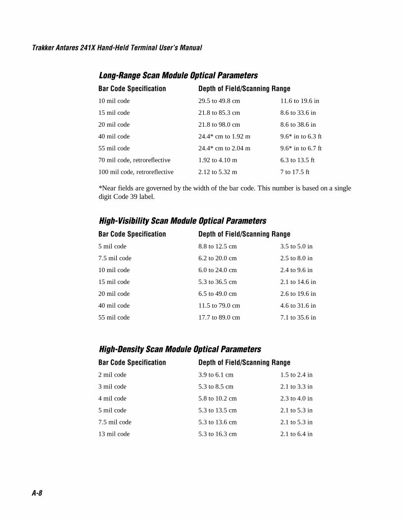
Trakker Antares 241X Hand-Held Terminal User’s Manual Co de 39 Nugget
A-8
Long-Range Scan Module Optical ParametersBar Code Specification Depth of Field/Scanning Range
10 mil code 29.5 to 49.8 cm 11.6 to 19.6 in
15 mil code 21.8 to 85.3 cm 8.6 to 33.6 in
20 mil code 21.8 to 98.0 cm 8.6 to 38.6 in
40 mil code 24.4* cm to 1.92 m 9.6* in to 6.3 ft
55 mil code 24.4* cm to 2.04 m 9.6* in to 6.7 ft
70 mil code, retroreflective 1.92 to 4.10 m 6.3 to 13.5 ft
100 mil code, retroreflective 2.12 to 5.32 m 7 to 17.5 ft
*Near fields are governed by the width of the bar code. This number is based on a singledigit Code 39 label.
High-Visibility Scan Module Optical ParametersBar Code Specification Depth of Field/Scanning Range
5 mil code 8.8 to 12.5 cm 3.5 to 5.0 in
7.5 mil code 6.2 to 20.0 cm 2.5 to 8.0 in
10 mil code 6.0 to 24.0 cm 2.4 to 9.6 in
15 mil code 5.3 to 36.5 cm 2.1 to 14.6 in
20 mil code 6.5 to 49.0 cm 2.6 to 19.6 in
40 mil code 11.5 to 79.0 cm 4.6 to 31.6 in
55 mil code 17.7 to 89.0 cm 7.1 to 35.6 in
High-Density Scan Module Optical ParametersBar Code Specification Depth of Field/Scanning Range
2 mil code 3.9 to 6.1 cm 1.5 to 2.4 in
3 mil code 5.3 to 8.5 cm 2.1 to 3.3 in
4 mil code 5.8 to 10.2 cm 2.3 to 4.0 in
5 mil code 5.3 to 13.5 cm 2.1 to 5.3 in
7.5 mil code 5.3 to 13.6 cm 2.1 to 5.3 in
13 mil code 5.3 to 16.3 cm 2.1 to 6.4 in

Co de 39 Nugget Specifications and Other Helpful Information
A-9
ADefault Configuration
The next tables show the terminal’s default configuration. You can use the TRAKKERAntares 2400 Menu System to set the terminal to the default configuration. For help, see“Restoring the Terminal’s Default Configuration” in Chapter 3.
Default Configuration for Bar Code Symbologies
Parameter Default
Codabar Disabled
Code 11 Disabled
Code 16K Disabled
Code 2 of 5 Disabled
Code 39 Enabled, full ASCII Code 39 enabled with no check digit
Code 49 Disabled
Code 93 Disabled
Code 128 Enabled, standard
Interleaved 2 of 5 Disabled
ISBT Code 128 Disabled
MSI Disabled
Plessey Disabled
UPC/EAN Enabled, UPC-A/EAN-13 enabled, UPC-E and EAN-8 enabled,supplementals allowed, transmit check digit, transmit numbersystem digit, and retain leading zero for UPC-A

Trakker Antares 241X Hand-Held Terminal User’s Manual Co de 39 Nugget
A-10
Default Configuration for Operations
Parameter Default
Append Time Disabled
Automatic Shutoff Disabled
Beep Volume Very Loud
Command Processing All reader commands enabled
Decode Security Moderate
Display Backlight Timeout 10 seconds
Display Contrast 3 (maximum contrast)
Display Font Grid Type 8x8 (8 pixels wide by 8 pixels high)
Display Row Spacing 0 (one scan line)
Display Video Mode Original
Flash Memory Configuration Configure for double-byte fonts
Keypad Caps Lock Caps lock off
Keypad Clicker Enabled
Keypad Type Hardware default
Postamble No characters (disabled)
Preamble No characters (disabled)
RAM Drive Size No RAM drive
Resume Execution Allowed
Scan Ahead Disabled
Scanner Mode One-Shot mode
Scanner Redundancy Normal
Scanner Selection All compatible scanners
Scanner Timeout Disabled (no timeout)
Scanner Trigger Level triggering
Suspend/Resume Control Enabled
Time and Date 960101120000 (See note below.)
Time in Seconds Disabled
Note: When you restore the default configuration, the Time and Date is not reset to thedefault. Time and Date only returns to its default when you boot the system, upgrade thefirmware, or perform a destructive reset.
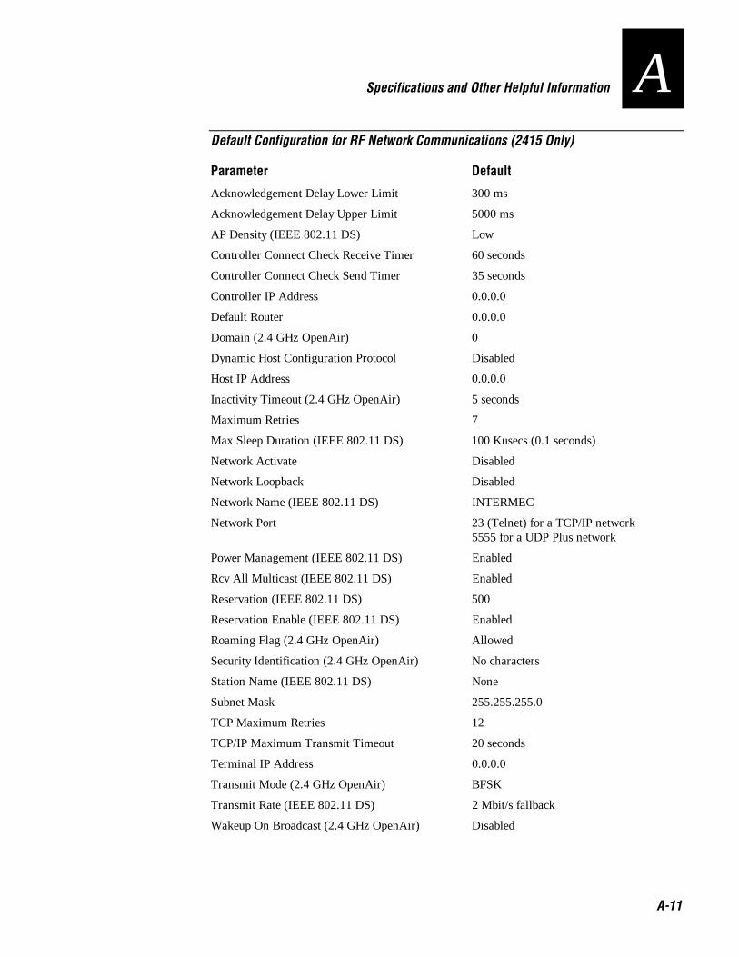
Co de 39 Nugget Specifications and Other Helpful Information
A-11
ADefault Configuration for RF Network Communications (2415 Only)
Parameter Default
Acknowledgement Delay Lower Limit 300 ms
Acknowledgement Delay Upper Limit 5000 ms
AP Density (IEEE 802.11 DS) Low
Controller Connect Check Receive Timer 60 seconds
Controller Connect Check Send Timer 35 seconds
Controller IP Address 0.0.0.0
Default Router 0.0.0.0
Domain (2.4 GHz OpenAir) 0
Dynamic Host Configuration Protocol Disabled
Host IP Address 0.0.0.0
Inactivity Timeout (2.4 GHz OpenAir) 5 seconds
Maximum Retries 7
Max Sleep Duration (IEEE 802.11 DS) 100 Kusecs (0.1 seconds)
Network Activate Disabled
Network Loopback Disabled
Network Name (IEEE 802.11 DS) INTERMEC
Network Port 23 (Telnet) for a TCP/IP network5555 for a UDP Plus network
Power Management (IEEE 802.11 DS) Enabled
Rcv All Multicast (IEEE 802.11 DS) Enabled
Reservation (IEEE 802.11 DS) 500
Reservation Enable (IEEE 802.11 DS) Enabled
Roaming Flag (2.4 GHz OpenAir) Allowed
Security Identification (2.4 GHz OpenAir) No characters
Station Name (IEEE 802.11 DS) None
Subnet Mask 255.255.255.0
TCP Maximum Retries 12
TCP/IP Maximum Transmit Timeout 20 seconds
Terminal IP Address 0.0.0.0
Transmit Mode (2.4 GHz OpenAir) BFSK
Transmit Rate (IEEE 802.11 DS) 2 Mbit/s fallback
Wakeup On Broadcast (2.4 GHz OpenAir) Disabled
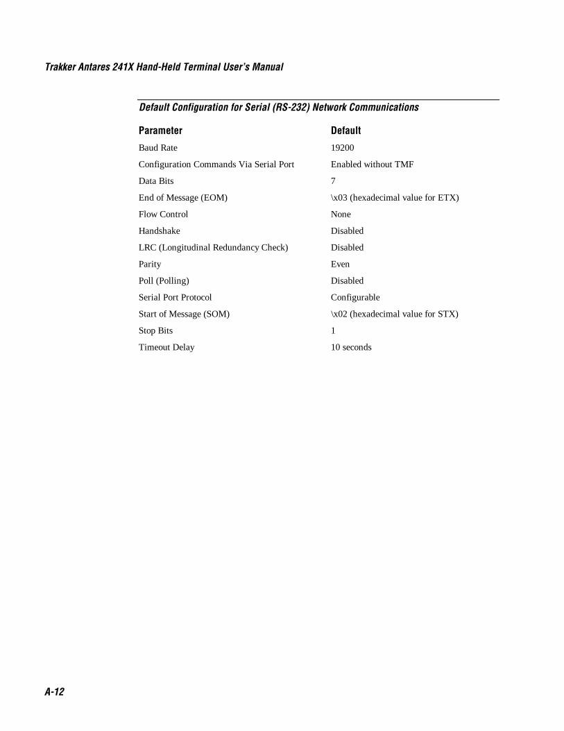
Trakker Antares 241X Hand-Held Terminal User’s Manual Co de 39 Nugget
A-12
Default Configuration for Serial (RS-232) Network Communications
Parameter Default
Baud Rate 19200
Configuration Commands Via Serial Port Enabled without TMF
Data Bits 7
End of Message (EOM) \x03 (hexadecimal value for ETX)
Flow Control None
Handshake Disabled
LRC (Longitudinal Redundancy Check) Disabled
Parity Even
Poll (Polling) Disabled
Serial Port Protocol Configurable
Start of Message (SOM) \x02 (hexadecimal value for STX)
Stop Bits 1
Timeout Delay 10 seconds

Co de 39 Nugget Specifications and Other Helpful Information
A-13
AConfiguration Commands by Syntax
The next table lists all of the configuration commands that are available on the TrakkerAntares 2410 and 2415 terminals. The configuration commands are listed in alphabeticorder by syntax.
Syntax Command
ADdata Preamble
AEdata Postamble
BVdata Beep Volume
CAdata Interleaved 2 of 5 Code (I 2 of 5)
CBdata Code 39
CCdata Code 2 of 5 (2 of 5)
CDdata Codabar
CEdata UPC/EAN
CFdata Code 93
CGdata Code 11
CHdata Code 128
CH8data ISBT Code 128
CIdata Plessey
CJdata Code 49
CKdata Code 49 Function Code 1
CLdata Code 49 Function Code 2
CMdata Code 49 Function Code 3
CNdata MSI
CPdata Code 16K
CSdata Decode Security
DAdata Time in Seconds
DBdata Time and Date
DCdata Command Processing
DEdata Append Time
DFdata Display Backlight Timeout
DJdata Display Contrast
DLdata Display Row Spacing
DNdata Display Video Mode
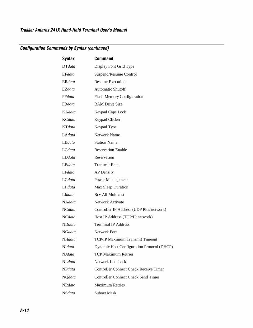
Trakker Antares 241X Hand-Held Terminal User’s Manual Co de 39 Nugget
A-14
Configuration Commands by Syntax (continued)
Syntax Command
DTdata Display Font Grid Type
EFdata Suspend/Resume Control
ERdata Resume Execution
EZdata Automatic Shutoff
FFdata Flash Memory Configuration
FRdata RAM Drive Size
KAdata Keypad Caps Lock
KCdata Keypad Clicker
KTdata Keypad Type
LAdata Network Name
LBdata Station Name
LCdata Reservation Enable
LDdata Reservation
LEdata Transmit Rate
LFdata AP Density
LGdata Power Management
LHdata Max Sleep Duration
LIdata Rcv All Multicast
NAdata Network Activate
NCdata Controller IP Address (UDP Plus network)
NCdata Host IP Address (TCP/IP network)
NDdata Terminal IP Address
NGdata Network Port
NHdata TCP/IP Maximum Transmit Timeout
NIdata Dynamic Host Configuration Protocol (DHCP)
NJdata TCP Maximum Retries
NLdata Network Loopback
NPdata Controller Connect Check Receive Timer
NQdata Controller Connect Check Send Timer
NRdata Maximum Retries
NSdata Subnet Mask

Co de 39 Nugget Specifications and Other Helpful Information
A-15
AConfiguration Commands by Syntax (continued)
Syntax Command
NUdata Acknowledgement Delay Upper Limit
NVdata Acknowledgement Delay Lower Limit
NXdata Default Router
RBdata Wakeup On Broadcast
RRdata Roaming Flag
RSdata Security Identification
RTdata Transmit Mode
RWdata Domain
RYdata Inactivity Timeout
SAdata Scanner Timeout
SBdata Scanner Mode
SCdata Scanner Trigger
SDdata Scan Ahead
SRdata Scanner Redundancy
SSdata Scanner Selection
YAn.data Baud Rate
YBn.data Parity
YCn.data Stop Bits
YEn.data Timeout Delay
YFn.data LRC (Longitudinal Redundancy Check)
YIn.data Data Bits
YJn.data Handshake (also know as AFF)
YLn.data Flow Control
YRn.data Poll (Polling)
YTn.data Configuration Commands Via Serial Port
YUn.data Serial Port Protocol
YYn.data Start of Message (SOM)
YZn.data End of Message (EOM)

A-16

Full ASCII Charts
B

B-2

Nugg Co de 39 Full ASCII Charts
B-3
BThis appendix contains the full ASCII table and the full ASCII chart of Code 39 barcode labels.
Full ASCII TableThis table lists the ASCII characters and their binary, hexadecimal, and Code 39equivalents.
Full ASCII Table
Binary0 Hex1 Decimal Code 39 ASCII2 Binary0 Hex1 Decimal Code 39 ASCII2
00000000 00 00 %U NUL 00100000 20 32 SP SP3
00000001 01 01 $A SOH 00100001 21 33 /A !00000010 02 02 $B STX 00100010 22 34 /B "00000011 03 03 $C ETX 00100011 23 35 /C #
00000100 04 04 $D EOT 00100100 24 36 /D $00000101 05 05 $E ENQ 00100101 25 37 /E %00000110 06 06 $F ACK 00100110 26 38 /F &00000111 07 07 $G BEL 00100111 27 39 /G '
00001000 08 08 $H BS 00101000 28 40 /H (00001001 09 09 $I HT 00101001 29 41 /I )00001010 0A 10 $J LF 00101010 2A 42 /J *00001011 0B 11 $K VT 00101011 2B 43 /K +
00001100 0C 12 $L FF 00101100 2C 44 /L ,00001101 0D 13 $M CR 00101101 2D 45 /M -00001110 0E 14 $N SO 00101110 2E 46 /N .00001111 0F 15 $O SI 00101111 2F 47 /O /
00010000 10 16 $P DLE 00110000 30 48 /P4 000010001 11 17 $Q DC1 00110001 31 49 /Q 100010010 12 18 $R DC2 00110010 32 50 /R 200010011 13 19 $S DC3 00110011 33 51 /S 3
00010100 14 20 $T DC4 00110100 34 52 /T 400010101 15 21 $U NAK 00110101 35 53 /U 500010110 16 22 $V SYN 00110110 36 54 /V 600010111 17 23 $W ETB 00110111 37 55 /W 7
00011000 18 24 $X CAN 00111000 38 56 /X 800011001 19 25 $Y EM 00111001 39 57 /Y 900011010 1A 26 $Z SUB 00111010 3A 58 /Z :00011011 1B 27 %A ESC 00111011 3B 59 %F ;
00011100 1C 28 %B FS 00111100 3C 60 %G <00011101 1D 29 %C GS 00111101 3D 61 %H =00011110 1E 30 %D RS 00111110 3E 62 %I >00011111 1F 31 %E US 00111111 3F 63 %J ?
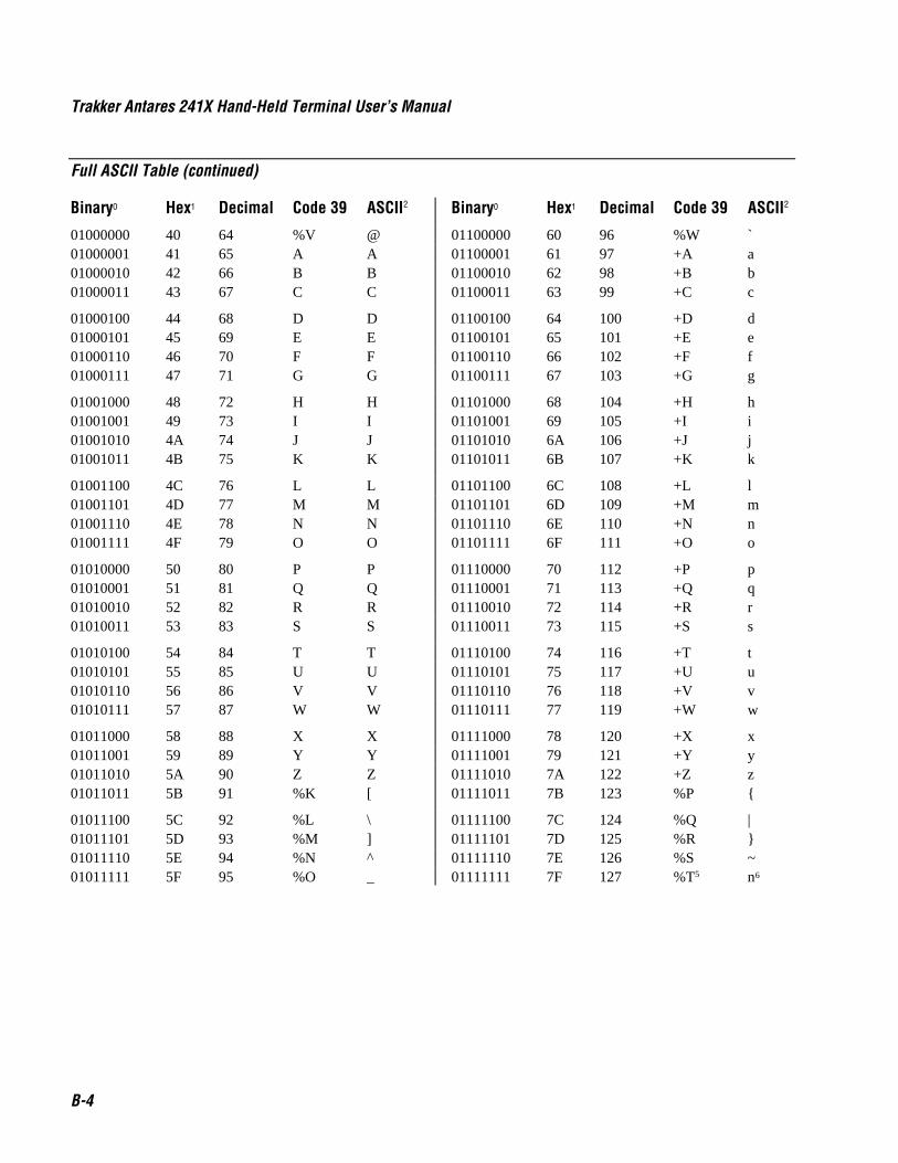
Trakker Antares 241X Hand-Held Terminal User’s Manual Nugg Co de 39
B-4
Full ASCII Table (continued)
Binary0 Hex1 Decimal Code 39 ASCII2 Binary0 Hex1 Decimal Code 39 ASCII2
01000000 40 64 %V @ 01100000 60 96 %W `01000001 41 65 A A 01100001 61 97 +A a01000010 42 66 B B 01100010 62 98 +B b01000011 43 67 C C 01100011 63 99 +C c
01000100 44 68 D D 01100100 64 100 +D d01000101 45 69 E E 01100101 65 101 +E e01000110 46 70 F F 01100110 66 102 +F f01000111 47 71 G G 01100111 67 103 +G g
01001000 48 72 H H 01101000 68 104 +H h01001001 49 73 I I 01101001 69 105 +I i01001010 4A 74 J J 01101010 6A 106 +J j01001011 4B 75 K K 01101011 6B 107 +K k
01001100 4C 76 L L 01101100 6C 108 +L l01001101 4D 77 M M 01101101 6D 109 +M m01001110 4E 78 N N 01101110 6E 110 +N n01001111 4F 79 O O 01101111 6F 111 +O o
01010000 50 80 P P 01110000 70 112 +P p01010001 51 81 Q Q 01110001 71 113 +Q q01010010 52 82 R R 01110010 72 114 +R r01010011 53 83 S S 01110011 73 115 +S s
01010100 54 84 T T 01110100 74 116 +T t01010101 55 85 U U 01110101 75 117 +U u01010110 56 86 V V 01110110 76 118 +V v01010111 57 87 W W 01110111 77 119 +W w
01011000 58 88 X X 01111000 78 120 +X x01011001 59 89 Y Y 01111001 79 121 +Y y01011010 5A 90 Z Z 01111010 7A 122 +Z z01011011 5B 91 %K [ 01111011 7B 123 %P {
01011100 5C 92 %L \ 01111100 7C 124 %Q |01011101 5D 93 %M ] 01111101 7D 125 %R }01011110 5E 94 %N ^ 01111110 7E 126 %S ~01011111 5F 95 %O _ 01111111 7F 127 %T5 n6
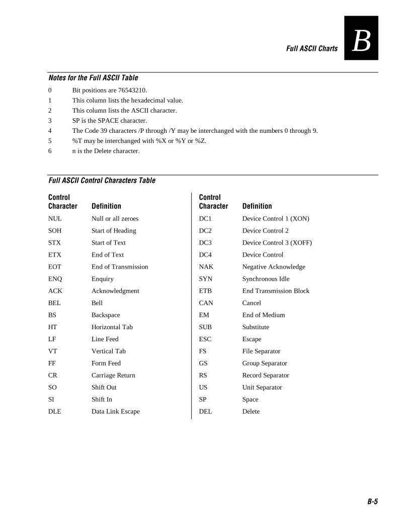
Nugg Co de 39 Full ASCII Charts
B-5
BNotes for the Full ASCII Table
0 Bit positions are 76543210.
1 This column lists the hexadecimal value.
2 This column lists the ASCII character.
3 SP is the SPACE character.
4 The Code 39 characters /P through /Y may be interchanged with the numbers 0 through 9.
5 %T may be interchanged with %X or %Y or %Z.
6 n is the Delete character.
Full ASCII Control Characters Table
ControlCharacter Definition
ControlCharacter Definition
NUL Null or all zeroes DC1 Device Control 1 (XON)
SOH Start of Heading DC2 Device Control 2
STX Start of Text DC3 Device Control 3 (XOFF)
ETX End of Text DC4 Device Control
EOT End of Transmission NAK Negative Acknowledge
ENQ Enquiry SYN Synchronous Idle
ACK Acknowledgment ETB End Transmission Block
BEL Bell CAN Cancel
BS Backspace EM End of Medium
HT Horizontal Tab SUB Substitute
LF Line Feed ESC Escape
VT Vertical Tab FS File Separator
FF Form Feed GS Group Separator
CR Carriage Return RS Record Separator
SO Shift Out US Unit Separator
SI Shift In SP Space
DLE Data Link Escape DEL Delete
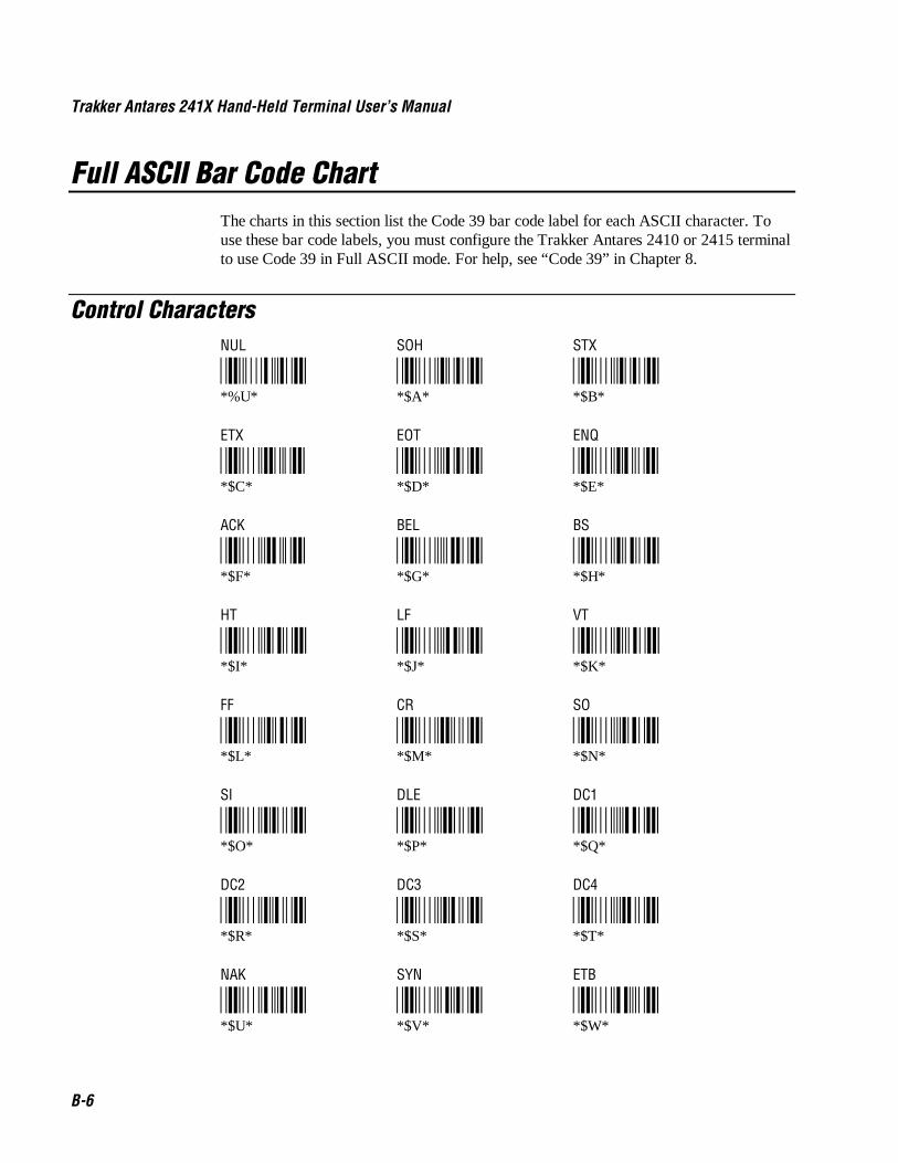
Trakker Antares 241X Hand-Held Terminal User’s Manual Nugg Co de 39
B-6
Full ASCII Bar Code ChartThe charts in this section list the Code 39 bar code label for each ASCII character. Touse these bar code labels, you must configure the Trakker Antares 2410 or 2415 terminalto use Code 39 in Full ASCII mode. For help, see “Code 39” in Chapter 8.
Control CharactersNUL SOH STX
*%U* *$A* *$B**%U* *$A* *$B*
ETX EOT ENQ
*$C* *$D* *$E**$C* *$D* *$E*
ACK BEL BS
*$F* *$G* *$H**$F* *$G* *$H*
HT LF VT
*$I* *$J* *$K**$I* *$J* *$K*
FF CR SO
*$L* *$M* *$N**$L* *$M* *$N*
SI DLE DC1
*$O* *$P* *$Q**$O* *$P* *$Q*
DC2 DC3 DC4
*$R* *$S* *$T**$R* *$S* *$T*
NAK SYN ETB
*$U* *$V* *$W**$U* *$V* *$W*

Nugg Co de 39 Full ASCII Charts
B-7
BControl Characters (continued)
CAN EM SUB
*$X* *$Y* *$Z**$X* *$Y* *$Z*
ESC FS GS
*%A* *%B* *%C**%A* *%B* *%C*
RS US DEL
*%D* *%E* *%T**%D* *%E* *%T*
Symbols and Punctuation Marks! (exclamation point) " (quotation marks) #
*/A* */B* */C**/A* */B* */C*
$ % &
*/D* */E* */F**/D* */E* */F*
' (apostrophe) ( )
*/G* */H* */I**/G* */H* */I*
* (asterisk) + - (dash)
*/J* */K* */M**/J* */K* */M*
/ = . (period)
*/O* *%H* */N**/O* *%H* */N*
, (comma) : (colon) ; (semicolon)
*/L* */Z* *%F**/L* */Z* *%F*

Trakker Antares 241X Hand-Held Terminal User’s Manual Nugg Co de 39
B-8
Symbols and Punctuation Marks (continued)
? < >
*%J* *%G* *%I**%J* *%G* *%I*
@ [ ]
*%V* *%K* *%M**%V* *%K* *%M*
~ (tilde) ^ _ (underline)
*%S* *%N* *%O**%S* *%N* *%O*
\ ` (left single quote) ¦ (pipe)
*%L* *%W* *%Q**%L* *%W* *%Q*
{ } Space
*%P* *%R* * **%P* *%R* * *
Numbers0 1 2
*0* *1* *2**0* *1* *2*
3 4 5
*3* *4* *5**3* *4* *5*
6 7 8
*6* *7* *8**6* *7* *8*
9
*9**9*
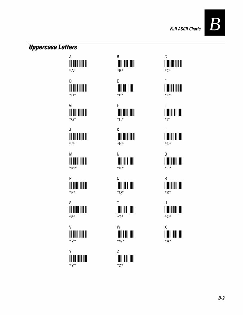
Nugg Co de 39 Full ASCII Charts
B-9
BUppercase Letters
A B C
*A* *B* *C**A* *B* *C*
D E F
*D* *E* *F**D* *E* *F*
G H I
*G* *H* *I**G* *H* *I*
J K L
*J* *K* *L**J* *K* *L*
M N O
*M* *N* *O**M* *N* *O*
P Q R
*P* *Q* *R**P* *Q* *R*
S T U
*S* *T* *U**S* *T* *U*
V W X
*V* *W* *X**V* *W* *X*
Y Z
*Y* *Z**Y* *Z*

Trakker Antares 241X Hand-Held Terminal User’s Manual Nugg Co de 39
B-10
Lowercase Lettersa b c
*+A* *+B* *+C**+A* *+B* *+C*
d e f
*+D* *+E* *+F**+D* *+E* *+F*
g h i
*+G* *+H* *+I**+G* *+H* *+I*
j k l
*+J* *+K* *+L**+J* *+K* *+L*
m n o
*+M* *+N* *+O**+M* *+N* *+O*
p q r
*+P* *+Q* *+R**+P* *+Q* *+R*
s t u
*+S* *+T* *+U**+S* *+T* *+U*
v w x
*+V* *+W* *+X**+V* *+W* *+X*
y z
*+Y* *+Z**+Y* *+Z*

International Character Support
C

C-2

Nugg Co de 39 International Character Support
C-3
CThis appendix lists some of the international characters that the terminal can display.
Trakker Antares Terminal Font SetThe Trakker Antares 2410 and 2415 terminals use an English and Western Europeanfont set that supports languages such as French, German, Italian, Portuguese, andSpanish. The terminal can also use a Japanese Katakana font set. You can developapplications that display the characters in either of the terminal font sets.
English and Western European Font SetThis table lists the characters that you can display on the terminal. The decimal, scancode, and hexadecimal values are the same for all keypads and overlays. The terminalkeys that are listed in the table are an example of the terminal keys that you press todisplay the character using the 55-key alphanumeric keypad with the internationaloverlay. Other keypads and overlays may require that you press different terminal keys todisplay the character.
Note: The terminal character set is similar to Microsoft’s DOS Code Page 850 with theexception of decimal characters 1 through 6 and 10 through 13. These characters werereplaced to provide additional line draw capability.
Character Terminal Keys Decimal Scan Code Hexadecimal
Space ; 0 03 00
h ; � 1 1E 01
i ; � 2 30 02
e ; � 3 2E 03
f ; 4 20 04
Z ; ! 5 12 05
Y ; " 6 21 06
 ; # 7 22 07
h 8 0E 08
o ; % 9 0F 09
j 10 24 0A
S ; ' 11 25 0B
T ; ( 12 26 0C
l 13 32 0D

Trakker Antares 241X Hand-Held Terminal User’s Manual Nugg Co de 39
C-4
English and Western European Character Set (continued)
Character Terminal Keys Decimal Scan Code Hexadecimalk ; * 14 31 0E
o ; + 15 18 0F
p ; , 16 19 10
q ; - 17 10 11
r ; . 18 13 12
s ; / 19 1F 13
¶ ; 0 20 14 14
§ ; 1 21 16 15
� ; 2 22 2F 16
w ; 3 23 11 17
È ; 4 24 2D 18
Ê ; 5 25 15 19
É ; 6 26 2C 1A
Ç ; � 27 01 1B
J ; � 28 2B 1C
} ; � 29 1B 1D
~ ; � / ; � 30 07 1E
� ; � 31 0C 1F
Space � � 32 39 20
! � � 33 02 21
" � ) 34 28 22
# � � 35 04 23
$ � � 36 05 24
% � � 37 06 25
& � � 38 08 26
’ � / 39 28 27
( � � 40 0A 28
) � 41 0B 29
* � � 42 09 2A

Nugg Co de 39 International Character Support
C-5
CEnglish and Western European Character Set (continued)
Character Terminal Keys Decimal Scan Code Hexadecimal
+ � � 43 0D 2B
, (comma) � 2 44 33 2C
- (dash) � $ 45 0C 2D
. (period) � / � 3 46 34 2E
/ � + / � 4 47 3F 2F
0 48 0B 30
1 � 49 02 31
2 � 50 03 32
3 � 51 04 33
4 � 52 05 34
5 � 53 06 35
6 � 54 07 36
7 � 55 08 37
8 � 56 09 38
9 � 57 0A 39
: � " 58 27 3A
; � ( 59 27 3B
< � , / � 60 33 3C
= � % 61 0D 3D
> � 62 34 3E
? � . 63 35 3F
@ � � 64 03 40
A � � 65 1E 41
B � � 66 30 42
C � � 67 2E 43
D � 68 20 44
E � ! 69 12 45
F � " 70 21 46
G � # 71 22 47
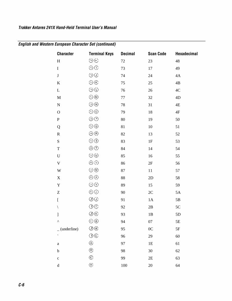
Trakker Antares 241X Hand-Held Terminal User’s Manual Nugg Co de 39
C-6
English and Western European Character Set (continued)
Character Terminal Keys Decimal Scan Code Hexadecimal
H � $ 72 23 48
I � % 73 17 49
J � & 74 24 4A
K � ' 75 25 4B
L � ( 76 26 4C
M � ) 77 32 4D
N � * 78 31 4E
O � + 79 18 4F
P � , 80 19 50
Q � - 81 10 51
R � . 82 13 52
S � / 83 1F 53
T � 0 84 14 54
U � 1 85 16 55
V � 2 86 2F 56
W � 3 87 11 57
X � 4 88 2D 58
Y � 5 89 15 59
Z � 6 90 2C 5A
[ � & 91 1A 5B
\ � 0 92 2B 5C
] � ' 93 1B 5D
^ � � 94 07 5E
_ (underline) � � 95 0C 5F
` � # 96 29 60
a � 97 1E 61
b � 98 30 62
c � 99 2E 63
d 100 20 64

Nugg Co de 39 International Character Support
C-7
CEnglish and Western European Character Set (continued)
Character Terminal Keys Decimal Scan Code Hexadecimal
e ! 101 12 65
f " 102 21 66
g # 103 22 67
h $ 104 23 68
i % 105 17 69
j & 106 24 6A
k ' 107 25 6B
l ( 108 26 6C
m ) 109 32 6D
n * 110 31 6E
o + 111 18 6F
p , 112 19 70
q - 113 10 71
r . 114 13 72
s / 115 1F 73
t 0 116 14 74
u 1 117 16 75
v 2 118 2F 76
w 3 119 11 77
x 4 120 2D 78
y 5 121 15 79
z 6 122 2C 7A
{ � 123 1A 7B
| (solid pipe) � - 124 2B 7C
} � ! 125 1B 7D
~ � � 126 29 7E
z 127 53E0 7F
Ç 128 2E 80
ü � 1 129 16 81

Trakker Antares 241X Hand-Held Terminal User’s Manual Nugg Co de 39
C-8
English and Western European Character Set (continued)
Character Terminal Keys Decimal Scan Code Hexadecimal
é � ! 130 12 82
â � � 131 1E 83
ä � � 132 1E 84
à � � 133 1E 85
å � 134 1A 86
ç � 135 2E 87
ê � ! 136 12 88
ë � ! 137 12 89
è � ! 138 12 8A
ï � % 139 17 8B
î � % 140 17 8C
ì � % 141 17 8D
Ä � � � 142 1E 8E
Å � 143 1A 8F
É � � ! 144 12 90
æ 145 4F00 91
Æ 146 7100 92
ô � + 147 18 93
ö � + 148 18 94
ò � + 149 18 95
û � 1 150 16 96
ù � 1 151 16 97
ÿ � 5 152 15 98
Ö � � + 153 18 99
Ü � � 1 154 16 9A
ø 155 E00D 9B
£ � 156 08 9C
Ø 157 50E0 9D
× 158 4BE0 9E
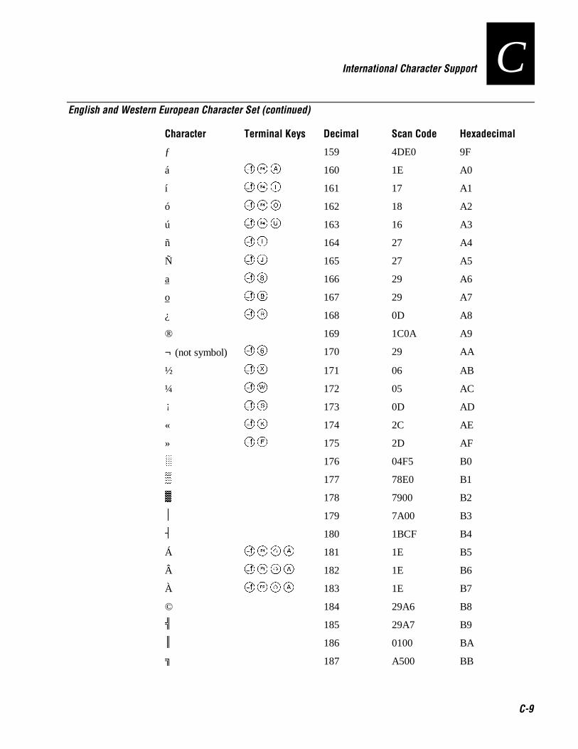
Nugg Co de 39 International Character Support
C-9
CEnglish and Western European Character Set (continued)
Character Terminal Keys Decimal Scan Code Hexadecimal
ƒ 159 4DE0 9F
á � � 160 1E A0
í � % 161 17 A1
ó � + 162 18 A2
ú � 1 163 16 A3
ñ % 164 27 A4
Ñ & 165 27 A5
a � 166 29 A6
o � 167 29 A7
¿ . 168 0D A8
® 169 1C0A A9
¬ (not symbol) � 170 29 AA
½ 4 171 06 AB
¼ 3 172 05 AC
¡ / 173 0D AD
« ' 174 2C AE
» " 175 2D AF
s 176 04F5 B0
t 177 78E0 B1
u 178 7900 B2
G 179 7A00 B3
M 180 1BCF B4
Á � � � 181 1E B5
 � � � 182 1E B6
À � � � 183 1E B7
© 184 29A6 B8
d 185 29A7 B9
R 186 0100 BA
X 187 A500 BB
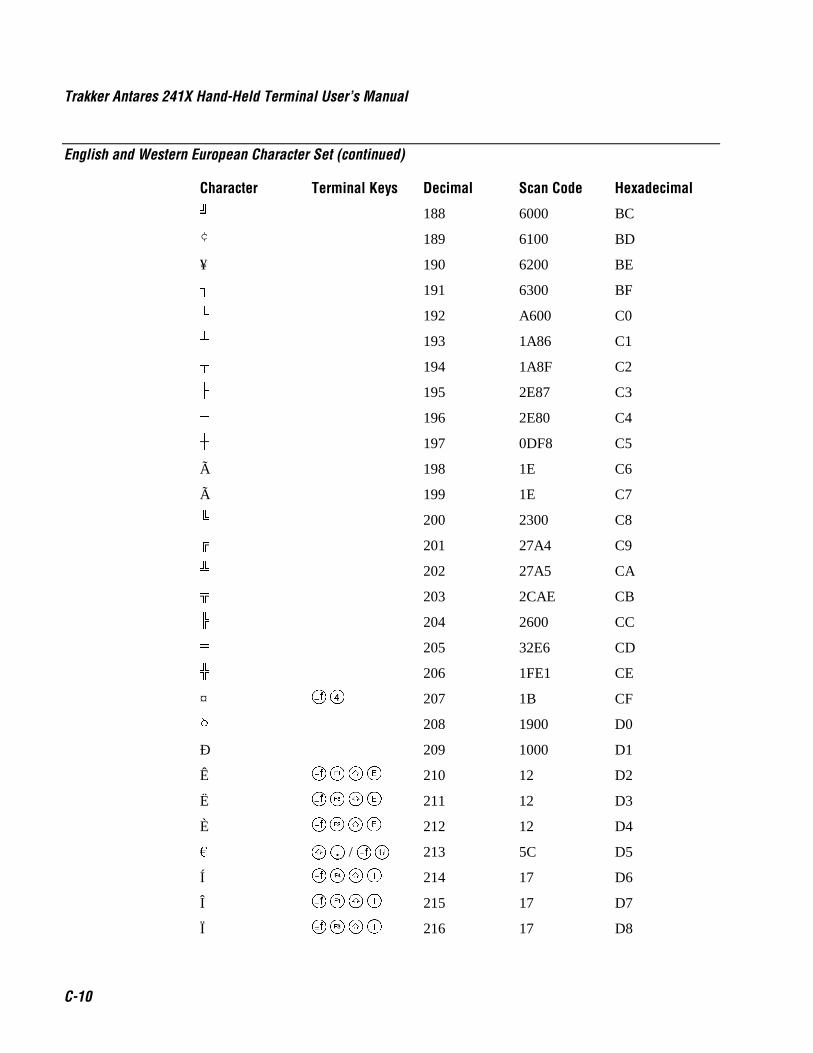
Trakker Antares 241X Hand-Held Terminal User’s Manual Nugg Co de 39
C-10
English and Western European Character Set (continued)
Character Terminal Keys Decimal Scan Code Hexadecimal^ 188 6000 BC
¢ 189 6100 BD
¥ 190 6200 BE
I 191 6300 BF
J 192 A600 C0
O 193 1A86 C1
N 194 1A8F C2
L 195 2E87 C3
F 196 2E80 C4
P 197 0DF8 C5
à 198 1E C6
à 199 1E C7
[ 200 2300 C8
U 201 27A4 C9
j 202 27A5 CA
g 203 2CAE CB
a 204 2600 CC
Q 205 32E6 CD
m 206 1FE1 CE
¤ � 207 1B CF
/ 208 1900 D0
Ð 209 1000 D1
Ê � � ! 210 12 D2
Ë � � ! 211 12 D3
È � � ! 212 12 D4
� � � / 1 213 5C D5
Í � � % 214 17 D6
Î � � % 215 17 D7
Ï � � % 216 17 D8

Nugg Co de 39 International Character Support
C-11
CEnglish and Western European Character Set (continued)
Character Terminal Keys Decimal Scan Code HexadecimalK 217 07F3 D9
H 218 2C00 DA
p 219 6D00 DB
o 220 0F00 DC
¦ (broken pipe) � * 221 56 DD
Ì � � % 222 17 DE
n 223 5A00 DF
Ó � � 224 52 / 78 E0
β * 225 1F E1
Ô � � + 226 18 E2
Ò � � + 227 18 E3
õ 228 18 E4
Õ 229 18 E5
µ ) 230 32 E6
Þ 231 4100 E7
þ 232 4200 E8
Ú � � 1 233 16 E9
Û � � 1 234 16 EA
Ù � � 1 235 16 EB
ý � 5 236 15 EC
Ý � � 5 237 15 ED
¯ 238 2EBD EE
´ � / 239 2EEE EF
- � 240 None F0
± 241 None F1
= � % 242 None F2
¾ 5 243 07 F3
¶ + 244 13 F4
§ 245 04 F5
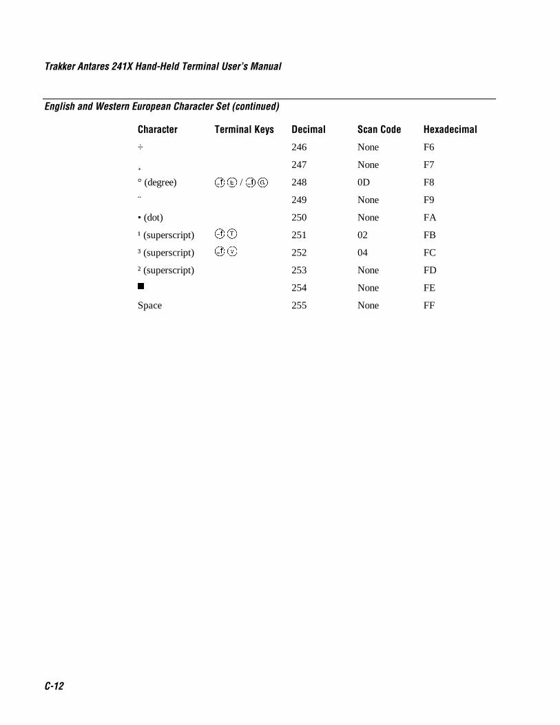
Trakker Antares 241X Hand-Held Terminal User’s Manual Nugg Co de 39
C-12
English and Western European Character Set (continued)
Character Terminal Keys Decimal Scan Code Hexadecimal
÷ 246 None F6
¸ 247 None F7
° (degree) ! / # 248 0D F8
¨ 249 None F9
• (dot) 250 None FA
¹ (superscript) 0 251 02 FB
³ (superscript) 2 252 04 FC
² (superscript) 253 None FD
v 254 None FE
Space 255 None FF
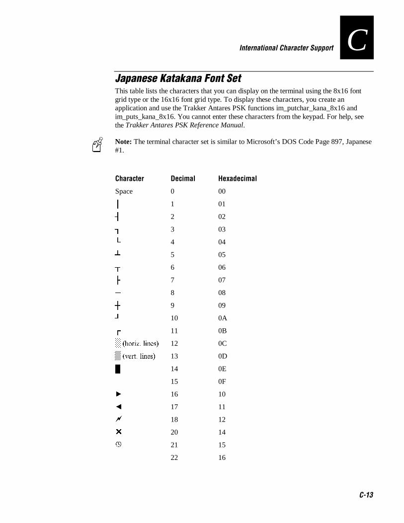
Nugg Co de 39 International Character Support
C-13
CJapanese Katakana Font SetThis table lists the characters that you can display on the terminal using the 8x16 fontgrid type or the 16x16 font grid type. To display these characters, you create anapplication and use the Trakker Antares PSK functions im_putchar_kana_8x16 andim_puts_kana_8x16. You cannot enter these characters from the keypad. For help, seethe Trakker Antares PSK Reference Manual.
Note: The terminal character set is similar to Microsoft’s DOS Code Page 897, Japanese#1.
Character Decimal Hexadecimal
Space 0 00
G 1 01
M 2 02
I 3 03
J 4 04
O 5 05
N 6 06
L 7 07
F 8 08
P 9 09
K 10 0A
H 11 0B
s �KRUL]� OLQHV� 12 0C
t �YHUW� OLQHV� 13 0D
p 14 0E
15 0F
y 16 10
{ 17 11
a 18 12
U 20 14
21 15
22 16
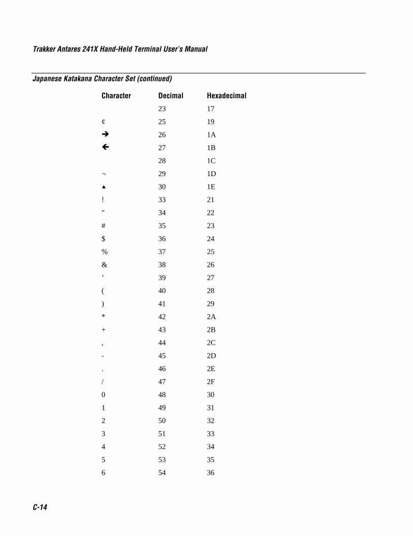
Trakker Antares 241X Hand-Held Terminal User’s Manual Nugg Co de 39
C-14
Japanese Katakana Character Set (continued)
Character Decimal Hexadecimal
23 17
¢ 25 19
Î 26 1A
Í 27 1B
28 1C
¬ 29 1D
~ 30 1E
! 33 21
" 34 22
# 35 23
$ 36 24
% 37 25
& 38 26
’ 39 27
( 40 28
) 41 29
* 42 2A
+ 43 2B
, 44 2C
- 45 2D
. 46 2E
/ 47 2F
0 48 30
1 49 31
2 50 32
3 51 33
4 52 34
5 53 35
6 54 36

Nugg Co de 39 International Character Support
C-15
CJapanese Katakana Character Set (continued)
Character Decimal Hexadecimal
7 55 37
8 56 38
9 57 39
: 58 3A
; 59 3B
< 60 3C
= 61 3D
> 62 3E
? 63 3F
@ 64 40
A 65 41
B 66 42
C 67 43
D 68 44
E 69 45
F 70 46
G 71 47
H 72 48
I 73 49
J 74 4A
K 75 4B
L 76 4C
M 77 4D
N 78 4E
O 79 4F
P 80 50
Q 81 51
R 82 52
S 83 53

Trakker Antares 241X Hand-Held Terminal User’s Manual Nugg Co de 39
C-16
Japanese Katakana Character Set (continued)
Character Decimal Hexadecimal
T 84 54
U 85 55
V 86 56
W 87 57
X 88 58
Y 89 59
Z 90 5A
[ 91 5B
¥ 92 5C
] 93 5D
^ 94 5E
_ 95 5F
‘ 96 60
a 97 61
b 98 62
c 99 63
d 100 64
e 101 65
f 102 66
g 103 67
h 104 68
I 105 69
j 106 6A
k 107 6B
l 108 6C
m 109 6D
n 110 6E
o 111 6F
p 112 70

Nugg Co de 39 International Character Support
C-17
CJapanese Katakana Character Set (continued)
Character Decimal Hexadecimal
q 113 71
r 114 72
s 115 73
t 116 74
u 117 75
v 118 76
w 119 77
x 120 78
y 121 79
z 122 7A
{ 123 7B
¦ (broken pipe) 124 7C
} 125 7D
~ 126 7E
161 A1
162 A2
163 A3
164 A4
 165 A5
� 166 A6
s 167 A7
� 168 A8
� 169 A9
� 170 AA
u 171 AB
x 172 AC
� 173 AD
o 174 AE
� 175 AF

Trakker Antares 241X Hand-Held Terminal User’s Manual Nugg Co de 39
C-18
Japanese Katakana Character Set (continued)
Character Decimal Hexadecimal
— 176 B0
$ 177 B1
% 178 B2
& 179 B3
' 180 B4
( 181 B5
) 182 B6
* 183 B7
+ 184 B8
, 185 B9
- 186 BA
. 187 BB
/ 188 BC
0 189 BD
1 190 BE
2 191 BF
3 192 C0
4 193 C1
5 194 C2
6 195 C3
7 196 C4
8 197 C5
9 198 C6
: 199 C7
; 200 C8
< 201 C9
= 202 CA
� 203 CB
# 204 CC

Nugg Co de 39 International Character Support
C-19
CJapanese Katakana Character Set (continued)
Character Decimal Hexadecimal
� 205 CD
� 206 CE
� 207 CF
A 208 D0
209 D1
210 D2
� 211 D3
� 212 D4
B 213 D5
� 214 D6
_ 215 D7
^ 216 D8
` 217 D9
� 218 DA
� 219 DB
a 220 DC
! 221 DD
" 222 DE
º 223 DF

TRAKKER Antares 241X Hand-Held Terminal User’s Manual Nugg Co de 39
C-20

Using the Default Applications
D

D-2
nugget Using the Default Applications
D-3
DThis appendix explains the APPTSK.BIN and EM9560.BIN applications that areshipped on the terminals. It also explains how to use each application.
About the Applications Shipped on the TerminalThe Trakker Antares 2410 and 2415 terminals ship loaded with at least these twoapplications:
• APPTSK.BIN
• EM9560.BIN
Both applications are stored on drive C. In addition to these two applications, yourterminal may have a TE 2000 application stored on drive C. This section explains how touse the APPTSK.BIN and EM9560.BIN applications. For help with your terminalemulation applications, see the appropriate terminal emulation programmer’s referenceguide.
Defining APPTSK.BIN and EM9560.BINYou can run and use APPTSK.BIN or EM9560.BIN at any time. The two applications aredefined as follows:
APPTSK.BIN This application is the default application on all terminals. In some errorconditions or if you exit an application, the terminal resets and runs APPTSK.BIN. Youcan use APPTSK.BIN to scan, enter, transmit, and display data.
EM9560.BIN This application emulates a subset of the functionality available on theIntermec 95XX terminals, such as the 9512 and 9560. You can use EM9560.BIN to scan,enter, transmit, and display data.
APPTSK.BIN and EM9560.BIN include these features:
• Works with any protocol that is supported on the terminal. Both the terminal and thedevice you are communicating with must use the same protocol (serial or RF) andparameter settings.
• Sends scanned or keyboard data out all serial or RF ports.
• Buffers the keyboard data until you press Enter.
• Receives data from any serial or RF port, displays the data on the terminal screen,and parses the data for commands.
• Receives data through any serial port and transmits it out the RF port.
• Receives data through the RF port and transmits it out all serial ports.
• (APPTSK.BIN only) Displays the time and date, which can be toggled on and off.
The main difference between the two applications is that you can use the EM9560.BINapplication to emulate specific functions of the 95XXs.

Trakker Antares 241X Hand-Held Terminal User’s Manual nugget
D-4
Defining the Emulation Features of EM9560.BINThese programmable terminals run C/C++ applications. With the EM9560.BINapplication, you can use the terminal as a remote input/output terminal in which allprompts and commands are controlled by the host computer. With this application, theterminal is similar to a 95XX in Data Entry mode with no application running.
Note: For the 95XXs, Data Entry mode with no application running is also referred to asan unprogrammed state or 95XX dumb terminal mode.
The EM9560.BIN application lets you use the terminal to emulate these specific 95XXfeatures:
• An Enter key without any preceding data transmits an empty data packet.
• The 241X display is similar to but not identical to the 9560 buffered display mode.
• All function keys transmit the corresponding characters F1, F2, and so on.
• When Code 128 is configured for Standard Code 128 symbology and you scan aUCC/EAN label, the terminal will discard the Function 1 characters. Although thisdoes not meet the industry standard for Code 128, it does emulate the 95XX, whichwas manufactured before the current standard was established. Other Code 128configurations work as defined in this user’s manual.
• The Set Time and Date reader (data entry) command is supported. When the terminalreceives a time broadcast command (/+) from the 9154 or 9161 controller, thecommand sets the clock on the terminal.
• The High Beep reader command is supported. When a backslash character (\) is sentto the terminal through any serial or network port, the terminal sounds a high beep.
• The Low Beep reader command is supported. When the BEL character is sent to theterminal through any serial or network port, the terminal sounds a low beep.
• When control codes (ANSI escape sequences) are sent to the terminal through anyserial or network port, the terminal formats the display. For a list of control codes,see “Using Display Control Codes” later in this appendix.
• Preamble A, Preamble B, and Postamble C are supported through the AA, AB, andAC configuration commands or through the reader commands +., ++, and +%. Forhelp, see “Setting Preambles and Postambles” later in this appendix.
• Full ASCII mode for Code 39 can be configured through the CB or RB configurationcommands or through the reader commands +$ and -$. For help, see “Full ASCIIMode for Code 39” later in this appendix.
• The Exit Configuration Mode, Save Settings configuration command ($-) is notrequired, but bar code labels with this command scan correctly.

nugget Using the Default Applications
D-5
DUsing Display Control CodesYou can use control codes to position the cursor or to format the terminal display. TheEM9560.BIN application recognizes the display control codes listed next.
Command Control Code Description or Action
Backspace BS (08 Hex) Moves the cursor one position to the left untilthe cursor reaches the first column. If thecursor is in the first column of any rowexcept the first row, a Backspace commandmoves the cursor to the last column of theprevious row.
Cursor Position ESC[n; vH Moves the cursor to the position specified bythe n and v parameters where:
n specifies the row or line number.
v specifies the column number.
If you enter zero or no parameter, n and v areset to one. If n or v exceeds the maximumrow or column number on the display, theparameters are set to the screen’s maximum.
Erase Display ESC[2J Erases the entire display and returns thecursor to the home position (row 1, column1). This command also erases the entirevirtual display image (buffer with up to fourrows of the most recently displayed data).
Home CR (0D Hex) Returns the cursor to the first column of thecurrent row.
Next Line LF (0A Hex) Moves the cursor down one row in thecurrent column position. If the cursor isalready in the last row, a new line is added.
Restore CursorPosition
ESC[u Restores the cursor position saved with aSave Cursor Position command. Each RestoreCursor Position command must be pairedwith a preceding Save Cursor Positioncommand. If a Save Cursor Positioncommand has not been previously entered,the cursor position will not change.
Save CursorPosition
ESC[s Saves the current cursor position. SuccessiveSave Cursor Position commands overwritethe previous position that was saved.

Trakker Antares 241X Hand-Held Terminal User’s Manual nugget
D-6
Setting Preambles and PostamblesWith the EM9560.BIN application, you can set Preamble A, Preamble B, and PostambleC on the 241X and make the terminal compatible with the 95XXs. The preambles areprepended and the postamble is appended to the data that is transmitted through all theserial ports.
Preamble A, Preamble B, and Postamble C can each be up to 25 ASCII characters inlength. If you enter a preamble or postamble command without entering data, thepreamble or postamble buffer is cleared.
Syntax: Preamble A AAdata or +.dataPreamble B ABdata or ++dataPostamble C ACdata or +%data
Scan: To set the preamble or postamble using the AA, AB, or AC configuration commands:
1. Scan one of these bar code labels:
Enter Accumulate Mode / Set Preamble A
*+/$+AA**+/$+AA*
Enter Accumulate Mode / Set Preamble B
*+/$+AB**+/$+AB*
Enter Accumulate Mode / Set Postamble C
*+/$+AC**+/$+AC*
2. Scan a value for data from the “Full ASCII Bar Code Chart” in Appendix B. Thepreamble or postamble can be from 1 to 25 characters.
3. Scan this bar code:
Exit Accumulate Mode
*-/**-/*
4. Repeat Steps 1 to 3 to set another preamble or postamble.

nugget Using the Default Applications
D-7
DOr: To set the preamble or postamble using the +., ++, or +% reader commands:
1. Scan one of these bar code labels:
Enter Accumulate Mode / Set Preamble A
*+/+.**+/+.*
Enter Accumulate Mode / Set Preamble B
*+/++**+/++*
Enter Accumulate Mode / Set Postamble C
*+/+%**+/+%*
2. Scan a value for data from the “Full ASCII Bar Code Chart” in Appendix B. Thepreamble or postamble can be from 1 to 25 characters.
3. Scan this bar code:
Exit Accumulate Mode
*-/**-/*
4. Repeat Steps 1 to 3 to set another preamble or postamble.
Full ASCII Mode for Code 39With the EM9560.BIN application, you can configure Full ASCII mode for Code 39 usingany of these commands:
• Code 39 configuration command (CB)
• Full ASCII configuration command (RB)
• Enter Full ASCII Mode reader command (+$) and the Exit Full ASCII Mode readercommand (-$)
The last two commands are compatible with the 95XXs. Each command is describednext. For help with the Code 39 configuration command (CB), see Chapter 8,“Configuration Command Reference.”
Note: Use the CB configuration command unless your terminals need to be compatiblewith the 95XXs in your data collection network.

Trakker Antares 241X Hand-Held Terminal User’s Manual nugget
D-8
Command: Full ASCII configuration command (RB)
Purpose: Configures the terminal to use Code 39 Full ASCII mode (enabled) or Code 39 Non-FullASCII mode (disabled). For a list of ASCII characters, see the “Full ASCII Table” inAppendix B.
Syntax: RBdata
Acceptable values for data are:
0 Disabled1 Enabled
Scan: One of these bar code labels:
Disable Full ASCII Mode Enable Full ASCII Mode
*$+RB0* *$+RB1**$+RB0* *$+RB1*
Command: Enter Full ASCII Mode reader command
Purpose: Enables Code 39 Full ASCII mode so the terminal decodes Code 39 bar code labels byusing a two-character encoding scheme to extend the character set to 128 characters. Fora list of ASCII characters, see the “Full ASCII Table” in Appendix B.
Syntax: +$
Scan: Full ASCII
*+$**+$*
Command: Exit Full ASCII Mode reader command
Purpose: Exits Code 39 Full ASCII mode and puts the terminal in Code 39 Non-Full ASCII mode(one-character encoding scheme).
Syntax: -$
Scan: Exit Full ASCII
*/M/D**-$*

nugget Using the Default Applications
D-9
DUnsupported 95XX FeaturesThese 95XX features are not supported by the EM9560.BIN application on the 241X.
• Display Setting configuration command (OD) (buffered or transparent display).
• Command Override reader (data entry) command (DLE).
• Right Host Message reader command (HT).
• Preamble A Required configuration command (OA).
• Computer Response Required Mode (CRRM) configuration command (PB), EnterCRRM reader command (./), and Exit CRRM reader command (.-).
• Resume IRL configuration command (XG).
• Separate transmit and receive EOM characters (PI and PJ). The configurable EOM(PF, YZ) is used for both transmit and receive EOM.
• Capacity reader command (%$).
• Forward and Review reader commands (%+ and %/).
• Download Program command from the 9154 or 9161 controller. Use the TransmitFile reader command. For help, see Chapter 7, “Reader Command Reference.”
Note: Although these 95XX features are not supported, the 241X does have manyadditional features (RF communications) that are not available on the 95XXs.
Running APPTSK.BIN and EM9560.BINThere are two ways to run APPTSK.BIN or EM9560.BIN:
• Use the Run Program reader command.
• Use the TRAKKER Antares 2400 Menu System.
The instructions in this section explain how to use the Run Program reader command.For help using the TRAKKER Antares 2400 Menu System to run an application, seeChapter 4, “Using Custom Applications.”
To run APPTSK.BIN or EM9560.BIN on the terminal
1. Scan one of these bar code labels:
Run APPTSK.BIN
*/O/OC/ZAPPTSK/NBIN**//C:APPTSK.BIN*
Run EM9560.BIN
*/O/OC/ZEM9560/NBIN**//C:EM9560.BIN*

Trakker Antares 241X Hand-Held Terminal User’s Manual nugget
D-10
Running APPTSK.BIN and EM9560.BIN (continued)
The terminal boots, resets all firmware, and runs the application. The initial screenfor the application appears. You see one of these screens:
APPTSK.BIN Screen EM9560.BIN Screen
1998/01/00 12:00:00
2. Scan this bar code label to toggle the clock display on or off.
Toggle Clock Display
*CLOCKDISPLAY**CLOCKDISPLAY*
3. Use the application to scan bar code labels, enter data through the keyboard, andtransmit data. The next section lists some examples of how you can use theapplications.
Example 1Use the application to troubleshoot and test communications before loading and runningyour data collection application. Connect the terminal to your network. Type data (“HelloWorld”) on the Trakker Antares terminal keyboard or scan a bar code label. The data issent out all serial and network ports and should be received by the host if your terminal isinstalled and configured correctly. Send data from the host and verify that the datadisplays on the terminal screen.
Example 2Connect a serial input device, such as a 2D scanner, to a serial port on the TrakkerAntares terminal. Data from the input device is displayed on the terminal screen andtransmitted out the network (RF) port.

nugget Using the Default Applications
D-11
DExample 3Connect the TD2400 communications dock to a serial port on the T2485. Use a T2420 tocollect data. Use the TD2400 communications dock to upload data from the T2420 to theT2485. Data is transmitted to the T2485 and out the RF port to the connected networkdevices.
Example 4Use the T248X as a gateway between the CrossBar network and the Ethernet or RFnetwork. Connect the T248X as a downline device in your CrossBar network. Connectthe T2480/1 with the Ethernet option to your Ethernet network, or connect the T2485/6to your RF network. While running the APPTSK.BIN or EM9560.BIN application, youcan send data from the Ethernet or RF network through the T248X to the 9154 or 9161and vice versa.
Example 5Connect the COM1 serial port to the COM2 serial port on a T246X or T248X terminal.Use the terminal to configure itself by typing and entering configuration commands onthe keypad or keyboard.
Example 6Connect the serial port on the T248X to the serial port on the T246X terminal. Use theT248X to configure the T246X by typing and entering configuration commands on theT248X keypad.

D-12

Index
I

I-2

Index
I-3
ISymbols� key, See Function Left key key, See Function Right key key, See backlight, key� key, See Shift key�, � keys, See cursor keys: key
configuring, 8-126configuring to boot the terminal, 5-18turning the terminal on and off, 1-32See also Suspend/Resume key
Numbers2.4 GHz RF network
activating, 8-88equipment required, 2-13installing, overview, 2-13protocols, defined, 2-17 to 2-20terminal, configuring, 2-16
2410described, 1-3drives, described, 1-22network, illustrated, 2-3, 2-4options, described, 1-4
2415applications, downloading, 4-16configuring
from host, 3-18 to 3-22using DCS 300, 3-17
configuring through network, 3-17 to 3-22described, 1-3drives, described, 1-22installing, overview, 2-13network parameters, configuring, 2-16network protocols, defined, 2-17 to 2-20network, illustrated, 2-3, 2-5, 2-6, 2-7, 2-8, 2-9options, described, 1-4RF communications, troubleshooting, 5-12
5250 terminal emulation, See TE 2000 5250 TerminalEmulation Programmer’s Guide
8-bit binary filesconverting to 7-bit ASCII files and transmitting, 7-25receiving as 7-bit ASCII files and converting, 7-17
900 MHz RF network, illustrated, 2-495XX terminals, Set Time and Date reader command, 7-12
AABC Codabar, 8-19Abort Program reader command, 7-13About TRAKKER Antares 2400 screen, defined, 3-5Access Point screen, defined, 6-20accessories, described, 1-5Accumulate mode, using reader commands, 7-4
Acknowledgement Delay Lower Limit command, 8-7Acknowledgement Delay Upper Limit command, 8-9active configuration, 3-3AFF command, 8-70Affirmative Acknowledge command, See Handshake
commandAIAG check digit, Code 39, 8-26alphanumeric keypads, options, described, 1-7American Blood Commission, See ABC Codabarantenna, internal, 1-6AP Density command, 8-11Append Time command, 8-12Application Efficiency screen, defined, 6-21Application Events screen, defined, 6-7Application Simulator, 4-6Application Simulator, defined, 4-6applications
APPTSK.BIN, default application, D-3converting binary files, 4-8converting JANUS and Trakker Antares, 4-7developing, 4-6downloading
from DCS 300, 4-16from host in a TCP/IP network, 3-23
EM9560.BIN, default application, D-3exiting, 7-13EZBuilder, developing with, 4-6Malloc diagnostic screen, defined, 6-22options, described, A-4PSK,developing with, 4-6restarting, 7-10running, 4-19, 7-22running APPTSK.BIN, D-9running EM9560.BIN, D-9TRAKKER Antares 2400 Menu System, using, 3-4 to 3-12
APPTSK.BIN applicationdefined, D-3running, D-9
ARP, defined, 2-20ASCII
bar code chart, B-6 to B-10Code 39, full, 8-25Code 39, mixed-full, 8-25Code 39, non-full, 8-25control characters
list of, B-5postamble and preamble, entering, 3-9
extended characters, configuring, 3-9table of character equivalents, B-3 to B-5
Asian fonts, loading, 5-25audio signals
keypad clicks, enabling or disabling, 8-78list of, 1-16testing, 6-12
auto-advancing through fields, configuring, 3-9
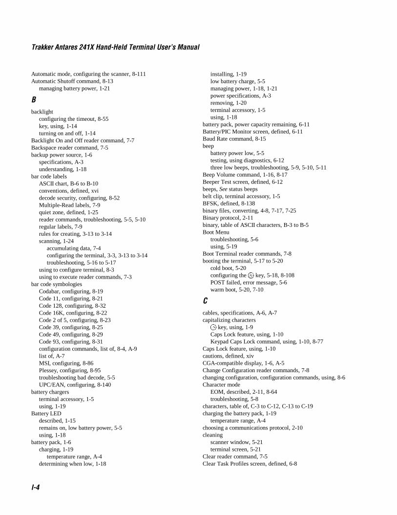
Trakker Antares 241X Hand-Held Terminal User’s Manual
I-4
Automatic mode, configuring the scanner, 8-111Automatic Shutoff command, 8-13
managing battery power, 1-21
Bbacklight
configuring the timeout, 8-55key, using, 1-14turning on and off, 1-14
Backlight On and Off reader command, 7-7Backspace reader command, 7-5backup power source, 1-6
specifications, A-3understanding, 1-18
bar code labelsASCII chart, B-6 to B-10conventions, defined, xvidecode security, configuring, 8-52Multiple-Read labels, 7-9quiet zone, defined, 1-25reader commands, troubleshooting, 5-5, 5-10regular labels, 7-9rules for creating, 3-13 to 3-14scanning, 1-24
accumulating data, 7-4configuring the terminal, 3-3, 3-13 to 3-14troubleshooting, 5-16 to 5-17
using to configure terminal, 8-3using to execute reader commands, 7-3
bar code symbologiesCodabar, configuring, 8-19Code 11, configuring, 8-21Code 128, configuring, 8-32Code 16K, configuring, 8-22Code 2 of 5, configuring, 8-23Code 39, configuring, 8-25Code 49, configuring, 8-29Code 93, configuring, 8-31configuration commands, list of, 8-4, A-9list of, A-7MSI, configuring, 8-86Plessey, configuring, 8-95troubleshooting bad decode, 5-5UPC/EAN, configuring, 8-140
battery chargersterminal accessory, 1-5using, 1-19
Battery LEDdescribed, 1-15remains on, low battery power, 5-5using, 1-18
battery pack, 1-6charging, 1-19
temperature range, A-4determining when low, 1-18
installing, 1-19low battery charge, 5-5managing power, 1-18, 1-21power specifications, A-3removing, 1-20terminal accessory, 1-5using, 1-18
battery pack, power capacity remaining, 6-11Battery/PIC Monitor screen, defined, 6-11Baud Rate command, 8-15beep
battery power low, 5-5testing, using diagnostics, 6-12three low beeps, troubleshooting, 5-9, 5-10, 5-11
Beep Volume command, 1-16, 8-17Beeper Test screen, defined, 6-12beeps, See status beepsbelt clip, terminal accessory, 1-5BFSK, defined, 8-138binary files, converting, 4-8, 7-17, 7-25Binary protocol, 2-11binary, table of ASCII characters, B-3 to B-5Boot Menu
troubleshooting, 5-6using, 5-19
Boot Terminal reader commands, 7-8booting the terminal, 5-17 to 5-20
cold boot, 5-20configuring the : key, 5-18, 8-108POST failed, error message, 5-6warm boot, 5-20, 7-10
Ccables, specifications, A-6, A-7capitalizing characters� key, using, 1-9Caps Lock feature, using, 1-10Keypad Caps Lock command, using, 1-10, 8-77
Caps Lock feature, using, 1-10cautions, defined, xivCGA-compatible display, 1-6, A-5Change Configuration reader commands, 7-8changing configuration, configuration commands, using, 8-6Character mode
EOM, described, 2-11, 8-64troubleshooting, 5-8
characters, table of, C-3 to C-12, C-13 to C-19charging the battery pack, 1-19
temperature range, A-4choosing a communications protocol, 2-10cleaning
scanner window, 5-21terminal screen, 5-21
Clear reader command, 7-5Clear Task Profiles screen, defined, 6-8

Index
I-5
ICLIENT.CPP sample application, 3-25Codabar command, 8-19Code 11 command, 8-21Code 128 command, 8-32Code 16K command, 8-22Code 2 of 5 command, 8-23
disabled with Interleaved 2 of 5, 8-75Code 39
configuration command, 8-25table of ASCII characters, B-3 to B-5
Code 49 command, 8-29Code 93 command, 8-31cold boot, 5-20COM ports, See serial portsCOM1, 1-13
pin assignments, A-6See also serial port
Command Processing command, 8-33 to 8-42commands
configuration commands, using, 8-3conventions, defined, xviireader commands, using, 7-3TRAKKER Antares 2400 Menu System, selecting, 3-6
communicationscable specifications, A-6, A-7LEDs, using to monitor, 2-17network protocols, defined, 2-17 to 2-20radio options, A-5RF configuration commands, list of, A-11serial port configuration commands, list of, A-12troubleshooting, 5-14
communications dock, 1-13cable specifications, A-7charging batteries, 1-19network, illustrated, 2-3terminal accessory, 1-5
communications protocolsBinary, 2-11choosing, 2-10Configurable, 2-11Master Polling, 2-12Point-to-Point, 2-12Polling Mode D, 2-12
computer, See host computerConfigurable protocol, 2-11Configurable Serial Protocol, defined, 2-18configuration command
Beep Volume, 1-16Keypad Caps Lock, 1-10
configuration commandsAcknowledgement Delay Lower Limit, 8-7Acknowledgement Delay Upper Limit, 8-9AFF, 8-70AP Density, 8-11Append Time, 8-12
Automatic Shutoff, 1-21, 8-13Baud Rate, 8-15Beep Volume, 8-17category, listed by, 8-4Codabar, 8-19Code 11, 8-21Code 128, 8-32Code 16K, 8-22Code 2 of 5, 8-23Code 39, 8-25Code 49, 8-29Code 93, 8-31Command Processing, 8-33 to 8-42Configuration Commands Via Serial Port, 8-43configuring, overview of, 3-3Controller Connect Check Receive Timer, 8-45Controller Connect Check Send Timer, 8-47Controller IP Address, 8-49Data Bits, 8-51Decode Security, 1-26, 8-52Default Router, 8-53default settings, list of, A-9 to A-12Display Backlight Timeout, 1-14, 8-55Display Contrast, 8-57Display Font Grid Type, 8-58Display Row Spacing, 8-59Display Video Mode, 8-60Domain, 8-61Dynamic Host Configuration Protocol, 8-63EOM, 8-64Flash Memory Configuration, 8-66Flow Control, 8-68Handshake, 8-70host application, using to configure, 3-15 to 3-16Host IP Address, 8-71Inactivity Timeout, 8-73Interleaved 2 of 5, 8-75Keypad Caps Lock, 8-77Keypad Clicker, 1-16, 8-78Keypad Type, 8-79LRC, 8-81Maximum Retries, 8-82Maximum Sleep Duration, 8-84MSI, 8-86Network Activate, 8-88Network Loopback, 8-89Network Name, 8-90Network Port, 8-92Parity, 8-94Plessey, 8-95Poll, 8-96Postamble, 8-97Power Management, 8-99Preamble, 8-100RAM Drive Size, 8-102

Trakker Antares 241X Hand-Held Terminal User’s Manual
I-6
configuration commands (continued)Receive All Multicast, 8-104Reservation, 8-105Reservation Enable, 8-107Resume Execution, 8-108Roaming Flag, 8-109Scan Ahead, 1-26, 8-110Scanner Mode, 1-26, 8-111Scanner Redundancy, 1-26, 8-112Scanner Selection, 1-26, 8-113Scanner Timeout, 1-26, 8-114Scanner Trigger, 1-26, 8-116scanning labels to configure the terminal, 3-13 to 3-14Security ID, 8-117sending from host, 3-18 to 3-22sending from the DCS 300, 3-17Serial Port Protocol, 8-118SOM, 8-120Station Name, 8-122Stop Bits, 8-123Subnet Mask, 8-124Suspend/Resume Control, 8-126syntax, listed by, A-13TCP Maximum Retries, 8-127TCP/IP Maximum Transmit Timeout, 8-129Terminal IP Address, 8-131Time and Date, 8-133Time in Seconds, 8-135Timeout Delay, 8-136Transmit Mode, 8-138Transmit Rate, 8-139troubleshooting, 5-9, 5-10, 5-11UPC/EAN, 8-140using, 8-3variable data, entering, 8-6Wakeup On Broadcast, 8-143
Configuration Commands Via Serial Port command, 8-43configuration files
active, 3-3current, 3-3default, 3-3
Configuration Menuexiting and saving changes, 3-11problems while exiting, 5-6 to 5-11
Configure Device Initialization Download dialog box, 4-17configuring
2.4 GHz RF network, overview, 2-13bar code labels, scanning, 3-13 to 3-14booting the terminal on resume, 5-18Change Configuration command, using, 7-8Default Configuration command, using, 7-9default settings, list of, A-9 to A-12host application, using, 3-15 to 3-16
remotely2415 from DCS 300, 3-172415 from host, 3-18 to 3-22
Save Configuration command, using, 7-10serial port parameters, 2-11, 2-12summary of methods, 3-3TRAKKER Antares 2400 Menu System, using, 3-4 to 3-12troubleshooting, 5-6 to 5-11
configuring, overview of configuration parameters, 3-3Connect LED
blinks, troubleshooting, 2-17, 5-12off, troubleshooting, 5-12
connecting an input device, 1-17connectivity options, described, A-4contrast, adjusting, 8-57control characters
bar code labels to scan, B-6full ASCII, list of, B-5
Controller Connect Check Receive Timer command, 8-45Controller Connect Check Send Timer command, 8-47Controller IP Address command, 8-49conventions
bar codes, defined, xvicommands, defined, xviikeypad, defined, xviscreens and messages, defined, xvwarnings and cautions, defined, xiv
converting applicationsbetween JANUS and Trakker Antares, 4-7from IRL, 4-7to binary, 4-8
copying filesnetwork communications, using, 3-23RF communications, using, 4-14to the 2415, 3-23, 4-16to the DCS 300, 4-14
country code, displayed, 6-15creating applications, 4-6CrossBar network
receiving and converting files, 7-17transmitting and converting files, 7-25
CTS/RTS, set by flow control, 8-68current configuration, 3-3cursor keys, using, 1-10customizing the terminal, 3-3
DData Bits command, 8-51data, accumulating in commands, 7-4, 8-6date, configuring, 8-133DCS 300
applications, downloading to terminal, 4-16copying applications and files, 4-14

Index
I-7
IDCS 300 (continued)
transaction ID, creating, 3-19troubleshooting, 5-15using to configure terminal, 3-17using to transfer applications, 4-14
decimalJapanese Katakana characters, values, C-13 to C-19key code values, displaying, 6-16table of ASCII characters, B-3 to B-5Western European characters, values, C-3 to C-12
Decode Security command, 1-26, 8-52default configuration, 3-3
list of, A-9 to A-12Default Configuration reader command, 7-9Default Router command, 8-53
determining when to configure, 2-16defining
APPTSK.BIN, D-3EM9560.BIN, D-3terminal’s drives, 1-22
defining EM9560.BIN, D-4Delete File reader command, 7-14Destructive RAM Test screen, defined, 6-13determining when the battery pack is low, 1-18developing applications, 4-6DHCP, See Dynamic Host Protocol Configuration commanddiacritical marks, typing, 1-12diagnostics
Access Point screen, defined, 6-20Application Efficiency screen, defined, 6-21Application Events screen, defined, 6-7Battery/PIC Monitor screen, defined, 6-11Beeper Test screen, defined, 6-12Clear Task Profiles screen, defined, 6-8Destructive RAM Test screen, defined, 6-13Diagnostics Menu, using, 6-5Display Test screen, defined, 6-14Error Logger screen, defined, 6-9Hardware Configuration screen, defined, 6-15Keypad Test screen, defined, 6-16Malloc Application Information screen, defined, 6-22Malloc Firmware Information screen, defined, 6-23Radio Test screen, defined, 6-17Scanner Test screen, defined, 6-18Serial Port Loopback screen, defined, 6-19Serial Port Test screen, defined, 6-24Subsystem Versions screen, defined, 6-25summary of, 6-3Task Status screen, defined, 6-10tests and screens, defined, 6-7 to 6-25TRAKKER Antares 2400 Menu System, using, 6-5
dimensions, of the terminal, A-3display, 1-6
backlight on and off, 7-7Display Backlight Timeout command, 1-14, 8-55
Display Contrast command, 8-57Display Font Grid Type command, 8-58Display Row Spacing command, 8-59Display Test screen, defined, 6-14Display Video Mode command, 8-60documentation
bar code conventions, defined, xvicommand conventions, defined, xviikeypad conventions, defined, xviscreen and message conventions, defined, xvwarnings and cautions, defined, xiv
Domain command, 8-61double-byte fonts, loading, 5-25downloading applications
network communications, using, 3-23overview, 4-3RF communications, using, 4-16using reader commands, 4-9using the DCS 300, 4-14using the FileCopy utility, 4-9using the LOADER.EXE program, 4-11
drive C, described, 1-22drive D, described, 1-22, 8-66drive E, described, 1-22drive G, described, 1-22Dynamic Host Configuration Protocol command, 8-63
EEAN-8, enabling, 8-140edge triggering, configuring the scanner, 8-116electrical specifications, A-3EM9560.BIN application
defined, D-3display control codes, using, D-5emulation features, D-4full ASCII mode for Code 39, configuring, D-7preambles/postambles, setting, D-6running, D-9unsupported features, D-9
End of Message, See EOM commandEnter Accumulate Mode reader command, 7-6
using, 8-6Enter reader command, 7-6entering data
configuration commands, using, 8-6keypad, using, 1-7reader commands, using, 7-4terminal locked up, 5-6
EOM command, 2-11, 8-64equipment, required for network, 2-13Error Logger screen, defined, 6-9error messages
audio signals, list of, 1-16DCS 300, 5-15EOM or SOM configuration error, 5-8, 5-9
Trakker Antares 241X Hand-Held Terminal User’s Manual
I-8
error messages (continued)network configuration error, 5-7, 5-8PG command failed error, 5-9POST failed, 5-6unable to connect to controller, 5-13
escape characters, entering in screens, 3-10Ethernet network
downloading files, 3-23illustrated, 2-4, 2-5, 2-6, 2-7, 2-8, 2-9
European Article Numbering, See UPC/EAN commandEuropean languages, table of characters, C-3 to C-12examples
2415, remotely configuring, 3-21, 3-22serial port, remotely configuring the terminal, 3-16
EXE2ABS.EXE program, using, 4-8Exit Accumulate Mode reader command, 7-6
using, 8-6exiting
applications, 7-13Configuration Menu, 3-11TRAKKER Antares 2400 Menu System, 3-11
extended ASCII characters, configuring, 3-9extended memory, specifications, A-5EZBuilder
binary files, converting, 4-8developing applications, 4-6
Ffeatures, described, 1-3, 1-6file management, using reader commands, 7-13File Manager, using to run applications, D-9FileCopy utility, 4-6, 4-7
using to run application, 4-19using to transfer applications, 4-9
filesconverting 7-bit to 8-bit, 7-17, 7-25deleting, 7-14naming conventions, described, 1-22renaming, 7-21transmitting, 7-23
network communications, using, 3-23RF communications, using, 4-16
finding the special keys, 1-8firmware
applications, restarting, 7-10checking the version loaded, 3-5Malloc diagnostic screen, defined, 6-23upgrading, 5-22
Boot Menu, using, 5-19versions, listed, 6-25
flash memorydefault configuration, saving, 7-9saving configuration changes, 3-11, 7-10specifications, A-5
Flash Memory Configuration command, 8-66
Flow Control command, 8-68font grid type, configuring, 8-58Frame mode
described, 2-11EOM, described, 8-64troubleshooting, 5-8
French, See European languagesfull ASCII
bar code chart of characters, B-6 to B-10Code 39, described, 8-25table of characters, B-3 to B-5
Function Code 1Code 128, using with, 8-32Code 16K, enable with, 8-22Code 49, enable with, 8-29
Function Code 2, Code 49, 8-29Function Code 3, Code 49, 8-29Function Left key, using, 1-9Function Right key, using, 1-9
GGerman, See European languagesGood Read status LED
described, 1-15troubleshooting, 5-16
green keys, using, 1-7
Hhandle, terminal accessory, 1-5Handshake command, 8-70handstrap, terminal accessory, 1-5Hardware Configuration screen, defined, 6-15hardware diagnostics
Battery/PIC Monitor screen, defined, 6-11Beeper Test screen, defined, 6-12Destructive RAM Test screen, defined, 6-13Display Test screen, defined, 6-14Hardware Configuration screen, defined, 6-15Keypad Test screen, defined, 6-16Radio Test screen, defined, 6-17Scanner Test screen, defined, 6-18Serial Port Loopback Test screen, defined, 6-19
Hardware Diagnostics menudiagnostic tests, defined, 6-11using, 6-6
Health Industry Bar Code, See HIBC, Code 39hexadecimal
Japanese Katakana characters, values, C-13 to C-19key code values, displaying, 6-16table of ASCII characters, B-3 to B-5Western European characters, values, C-3 to C-12
HIBC, Code 39, 8-26high-density scanner, optical parameters, A-8high-visibility scanner, optical parameters, A-8

Index
I-9
Iholster and belt, terminal accessory, 1-5horizontal reading angle for scanning, 1-25host computer
not receiving data, troubleshooting, 5-13transferring files, 3-23transmitting files, 7-19, 7-27using to configure 2415, 3-18 to 3-22
Host IP Address command, 8-71humidity, operating and storage range, A-4
II 2 of 5, See Interleaved 2 of 5 commandIEEE 802.11 DS network communications
AP density, configuring, 8-11maximum sleep duration, configuring, 8-84network name, configuring, 8-90power management, configuring, 8-99receive all multicast, configuring, 8-104reservation enable, configuring, 8-107reservation, configuring, 8-105station name, configuring, 8-122transmit rate, configuring, 8-139
Inactivity Timeout command, 8-73input devices
configuring for scanner, 8-113connecting to terminal, 1-17list of, 1-17troubleshooting, 5-16 to 5-17
installing2.4 GHz RF network, overview, 2-13serial port network, overview, 2-10
installing the battery pack, 1-19integrated I/O connector, 1-6
connecting input devices, 1-17specifications, A-5using, 1-13
Interactive Reader Language, See IRLInterleaved 2 of 5 command, 8-75
disabled with Code 2 of 5, 8-23Intermec support services, xiiiinternational languages
diacritical marks, typing, 1-12keypad, using, 1-11table of characters, C-3 to C-12, C-13 to C-19
IP addresscontroller, configuring, 8-49default router, configuring, 8-53host, configuring, 8-71terminal, configuring, 8-131using with DHCP, 8-49
IRL programs, converting, 4-7ISBT Code 128, enabling, 8-32Italian, See European languages
JJapanese Katakana font set, using, C-13 to C-19
KKatakana font set, using, C-13 to C-19key, conventions, defined, xvikeyclick, volume, adjusting from the keypad, 1-16keypad, 1-6 key, using, 1-14characters, capitalizing, 1-10conventions, defined, xvicursor keys, using, 1-10international, using, 1-11key code values, displaying, 6-16options, described, 1-7, A-4special keys, finding, 1-8TE, using, 1-12typing characters, 1-7using, 1-6 to 1-16
Keypad Caps Lock command, 1-10, 8-77Keypad Clicker command, 1-16, 8-78Keypad Test screen, defined, 6-16Keypad Type command, 8-79keys�, using, 1-9, using, 1-9�, using, 1-9:, using, 1-9, using, 1-14diacritical marks, typing, 1-12Scan button, 1-23
Llanguages, table of characters, C-3 to C-12, C-13 to C-19laser scanner, See scannerLEDs, See status LEDsletters, bar code labels to scan, B-9, B-10level triggering, configuring the scanner, 8-116List Files reader command, 7-15Load Default Values screen, using, 3-30loader, using the Boot Menu, 5-19LOADER.EXE program
using to transfer applications, 4-11using to upgrade firmware, 5-22
lock up, troubleshooting, 5-6Longitudinal Redundancy Check, See LRC commandlong-range scanner, optical parameters, A-8lowercase letters, bar code labels to scan, B-10LRC command, 8-81
Trakker Antares 241X Hand-Held Terminal User’s Manual
I-10
MMain Board Menu, using, 6-12, 6-13Main Menu, options defined, 3-4Malloc Application Information screen, defined, 6-22Malloc Firmware Information screen, defined, 6-23managing battery power, 1-21manual
audience and purpose, described, xivbar code conventions, xvicommand conventions, xviikeypad conventions, xvisoftware screens and messages conventions, xvterminology, defined, xv
Master Polling protocol, 2-12Maximum Retries command, 8-82Maximum Sleep Duration command, 8-84memory
flash, saving configuration changes, 3-11RAM, saving configuration changes, 3-11specifications, A-5troubleshooting, 6-13
menu system, See TRAKKER Antares 2400 Menu Systemmenus
Diagnostics Menu, defined, 6-5Main Menu, defined, 3-4TRAKKER Antares 2400 Menu System, selecting, 3-6
messages, conventions defined, xvmixed-full ASCII, Code 39, 8-25Modifier status LED, 1-9, 1-10
described, 1-15MSI command, 8-86Multi-Drop protocol
receiving and converting files, 7-17transmitting and converting files, 7-25
Multiple-Read Labels reader command, 7-9
NNET port, 1-13network
equipment required for 2.4 GHz, 2-13illustrated, 2-4, 2-5, 2-6, 2-7, 2-8, 2-9installing, overview, 2-13protocols, defined, 2-17 to 2-20
Network Activate command, 8-88network communications, troubleshooting, 5-12, 5-14Network Connect status LED, described, 1-15, 2-17Network Loopback command, 8-89Network Name command, 8-90Network Port command, 8-92non-full ASCII, Code 39, 8-25notes, defined, xivnumbers, bar code labels to scan, B-8numeric keypads, options, described, 1-7
OOne-Shot mode, configuring the scanner, 8-111OpenAir network communications
domain, configuring, 8-61inactivity timeout, configuring, 8-73roaming flag, configuring, 8-109security ID, configuring, 8-117Transmit mode, configuring, 8-138wakeup on broadcast, configuring, 8-143See also 2.4 GHz RF network
operating the terminalconfiguration commands, list of, 8-4, A-10humidity range, A-4reader commands
enabling or disabling, 8-33 to 8-42using, 7-3, 7-7
temperature range, A-4troubleshooting, 5-5 to 5-6
options, described, 1-4orange keys, using, 1-7OSI model, network protocols, defining, 2-17 to 2-20
Pparameters, overview for configuration, 3-3Parity command, 8-94pin assignments, A-6pink keys, using, 1-7Plessey command, 8-95Point-to-Point protocol, 2-12Poll command, 8-96Polling Mode D protocol, 2-12Portuguese, See European languagesPOST
failed, error message, 5-6failed, status beeps, 1-16success, status beeps, 1-16
postambleASCII control characters, entering, 3-9EM9560.BIN application, setting, D-6Field Exit, configuring to auto-advance, 3-9
Postamble command, 8-97power
backup power source, A-3battery pack specifications, A-3
power managementautomatic shutoff, using, 8-13battery capacity remaining, 6-11battery pack, using, 1-18guidelines for, 1-21resume, suspend, and boot, 8-108Wakeup On Broadcast, disabling, 8-143
Power Management command, 8-99

Index
I-11
Ipreamble
ASCII control characters, entering, 3-9EM9560.BIN application, setting, D-6Field Exit, configuring to auto-advance, 3-9
Preamble command, 8-100Preamble/Postamble screen, using, 3-9print quality, bar code, 8-52, 8-112problems, finding and solving, 5-4program, See applicationsProgrammer's Software Kit, See PSKprotocol stack
checking the protocol loaded, 3-5, 6-10OSI model, defined, 2-17 to 2-20
PSKapplications, developing, 4-6binary files, converting, 4-8IRL programs, converting, 4-7JANUS and Trakker Antares, converting applications, 4-7
punctuation marks, bar code labels to scan, B-7
QQFSK, defined, 8-138quiet zone, bar code labels, 1-25quotation marks in commands, using, 3-14
Rradio
country code, displayed, 6-15troubleshooting, 5-12, 6-17options, A-5
Radio Test screen, defined, 6-17RAM
default configuration, saving, 7-9saving configuration changes, 3-11specifications, A-5troubleshooting, 6-13
RAM Drive Size command, 8-102Reader Command Menu, using, 3-8reader commands
Abort Program, 7-13Accumulate mode, using, 7-4Backlight On and Off, 7-7Backspace, 7-5Boot Terminal, 7-8Change Configuration, 7-8Clear, 7-5Default Configuration, 7-9Delete File, 7-14enabling or disabling, 8-33 to 8-42Enter, 7-6Enter Accumulate mode, 7-6Exit Accumulate mode, 7-6file management commands, 7-13host application, using to configure, 3-15 to 3-16
List Files, 7-15Multiple-Read Labels, 7-9operating commands, 7-7Receive File, 7-15Rename File, 7-21Reset Firmware, 7-10Run Program, 7-22Save Configuration, 7-10Scanner Trigger On and Off, 7-11scanning labels to configure the terminal, 3-13 to 3-14sending from host, 3-18 to 3-22sending from the DCS 300, 3-17Set Time and Date, 7-12Test and Service Mode, 7-12Transmit File, 7-23troubleshooting, 5-5, 5-10using, 7-3using to transfer applications, 4-9
Receive All Multicast command, 8-104Receive File reader command, 7-15relative humidity specifications, A-4removing the battery pack, 1-20Rename File reader command, 7-21Reservation command, 8-105Reservation Enable command, 8-107Reset Firmware reader command, 7-10resetting the terminal, 5-17 to 5-20, 7-10Restore User Files dialog box, 4-15Resume Execution command, 8-108resume, booting the terminal, 5-18RF communications
acknowledgement delay lower limit, configuring, 8-7acknowledgement delay upper limit, configuring, 8-9activating the 2.4 GHz RF network, 8-88configuration commands, list of, 8-5, A-11controller connect check receive timer, configuring, 8-45controller connect check send timer, configuring, 8-47controller IP address, configuring, 8-49default router, configuring, 8-53DHCP, configuring, 8-63downloading files, 3-23downloading files to the 2415, 4-16host IP address, configuring, 8-71maximum retries, configuring, 8-82network port, configuring, 8-92overview, 2-13radio options, A-5Receive File reader command, 7-19site survey, planning, 2-13status LEDs, using to monitor, 2-17subnet mask, configuring, 8-124TCP maximum retries, configuring, 8-127TCP maximum transmit timeout, configuring, 8-129terminal IP address, configuring, 8-131transferring files, 4-14

Trakker Antares 241X Hand-Held Terminal User’s Manual
I-12
RF communications (continued)Transmit File reader command, 7-27troubleshooting, 5-12
RF networkillustrated, 2-4, 2-5, 2-6, 2-7, 2-8, 2-9using to configure terminal, 8-3
RF network protocol, terminal, checking the protocol loaded,3-5, 6-10
RF port, 1-13Roaming Flag command, 8-109row spacing, configuring, 8-59Run Program reader command, 4-19, 7-22running applications, 4-3, 4-19runtime configuration, defined, 3-11
Ssafety procedures, xiiiSave and Activate sidebar button, 3-3Save Configuration sidebar button, 3-3saving configuration changes
Configuration Menu, exiting, 3-11reader command, using, 7-10TRAKKER Antares 2400 Menu System, exiting, 3-11
Scan Ahead command, 1-26, 8-110Scan button, using, 1-23scan codes, Western European characters, values, C-3 to C-12scanner
configuring for input devices, 8-113connecting to terminal, 1-17high-density opticial parameters, A-8high-visibility opticial parameters, A-8long-range opticial parameters, A-8standard range opticial parameters, A-7troubleshooting, 5-16 to 5-17
Scanner Mode command, 1-26, 8-111Scanner Redundancy command, 1-26, 8-112Scanner Selection command, 1-26, 8-113Scanner Test screen, defined, 6-18Scanner Timeout command, 1-26, 8-114Scanner Trigger command, 1-26, 8-116
On and Off reader command, 7-11scanning
ASCII characters, list of labels, B-6 to B-10bar code labels, 1-24button/trigger operation, configuring, 8-111options, defined, 1-26reader commands, using, 7-11Scan Ahead command, configuring, 8-110timeout, configuring, 8-114troubleshooting, 5-16 to 5-17
screencleaning, 5-21contrast, adjusting from the keypad, 1-14
conventions, defined, xvspecifications, A-5troubleshooting, 6-14
screen mapping, using, 4-21Security ID command, 8-117
ID not being saved, 5-7Serial Port Loopback screen, defined, 6-19serial port, 1-6
cable specifications, A-6communications, troubleshooting, 5-14configuration commands, list of, 8-5, A-12configuring parameters, 2-11network, illustrated, 2-3, 2-4Receive File reader command, 7-15, 7-17specifications, A-5Transmit File reader command, 7-23, 7-25transmitting files, 7-15, 7-23troubleshooting, 5-6 to 5-11using, 1-13using to configure terminal, 8-3using to configure the terminal, 3-15 to 3-16using to transfer applications, 4-9
serial port communicationsbaud rate, configuring, 8-15configuration commands via serial port, configuring, 8-43LRC, configuring, 8-81parity, configuring, 8-94poll, configuring, 8-96postamble, configuring, 8-97preamble, configuring, 8-100serial port protocol, configuring, 8-118stop bits, configuring, 8-123timeout delay, configuring, 8-136
Serial Port Protocol command, 8-118Serial Port Test screen, defined, 6-24Set Time and Date reader command, 7-12Shift key, using, 1-9sidebar buttons
Save and Activate, 3-3Save Configuration, 3-3
Simulator, See Application Simulatorsite survey, planning, 2-13software diagnostics
Application Events screen, defined, 6-7Clear Task Profiles screen, defined, 6-8Error Logger screen, defined, 6-9Task Status screen, defined, 6-10
Software Diagnostics menudiagnostic tests, defined, 6-7using, 6-6
SOM command, 8-120Spanish, See European languagesspecial keys, finding, 1-8specifications, A-3

Index
I-13
Istandard range scanner
optical parameters, A-7troubleshooting, 6-18
Start of Message, See SOM commandstart/stop codes conventions, defined, xvistarting
applications, 4-19, D-9steps for using the terminal, 1-27TRAKKER Antares 2400 Menu System, 3-4, 3-28, 3-29
Station Name command, 8-122status beeps, 1-6
understanding, 1-16volume, adjusting from the keypad, 1-16
status LEDs, 1-6Battery, 1-15communications, using to monitor, 2-17Good Read, 1-15Modifier, 1-15Network Connect, 1-15, 2-17troubleshooting, 5-12understanding, 1-15User Defined, 1-15
Stop Bits command, 8-123Store Configuration screen, using, 3-28storing the terminal
humidity range, A-4temperature range, A-4
Subnet Mask command, 8-124determining when to configure, 2-16
subnetworksterminal, using across, 2-7, 2-8, 2-9See also network
Subsystem Versions screen, defined, 6-25Suspend mode
automatic shutoff, using, 8-13managing battery power, 1-21
Suspend/Resume Control command, 8-126Suspend/Resume key, using, 1-9symbols, bar code labels to scan, B-7syntax, configuration commands listed by, A-13system diagnostics
Access Point screen, defined, 6-20Application Efficiency screen, defined, 6-21Malloc Application Information screen, defined, 6-22Malloc Firmware Information screen, defined, 6-23Serial Port Test screen, defined, 6-24Subsytem Versions screen, defined, 6-25
System Diagnostics menudiagnostic tests, defined, 6-20using, 6-6
system message flag, defined, 3-19
TTask Status screen, defined, 6-10TCP Maximum Retries command, 8-127TCP/IP direct connect network
checking the protocol loaded, 3-5, 6-10CLIENT.CPP sample application, 3-25file management commands, using, 7-13firmware, upgrading, 5-22illustrated, 2-6, 2-9protocols, defined, 2-17 to 2-20reader commands, using, 7-3RF parameters, default values, 2-16transmitting files, 3-23, 7-19, 7-27
TCP/IP Maximum Transmit Timeout command, 8-129TCP/IP port, See Network Port commandTD2410 Communications Dock, See communications dockTE keypad
options, described, 1-7using, 1-12
temperaturecharging range, A-4operating and storage range, A-4
terminalaccessories, list of, 1-5applications, downloading, 3-23booting and resetting, 5-17 to 5-20characters, table of, C-3 to C-12, C-13 to C-19configuring
from host, 3-18 to 3-22summary of methods, 3-3using bar code labels, 3-13 to 3-14using serial port, 3-15 to 3-16using TRAKKER Antares 2400 Menu System, 3-4
configuring from DCS 300, 3-17default configuration, list of, A-9 to A-12diagnostics, using, 6-3 to 6-25dimensions, A-3double-byte fonts, loading, 5-25drives, described, 1-22features, described, 1-3, 1-6firmware, upgrading, 5-22getting started, list of steps, 1-27keypad options, described, 1-7managing power, 1-21manual, audience and purpose, xivoperating, troubleshooting, 5-5 to 5-6options, described, 1-4scanner, using, 1-23terminology, defined, xvtroubleshooting, guide to, 5-3, 5-4
Terminal Download Configuration dialog box, 4-16

Trakker Antares 241X Hand-Held Terminal User’s Manual
I-14
terminal emulationapplication options, A-4keypad options, 1-7, A-4session, problems establishing, 5-13status LEDs, using to monitor, 2-17
Terminal IP Address command, 8-131terminology, defined, xvTest and Service Mode reader command, 7-12TFTP
defined, 2-17 to 2-20server, using, 3-23
Time and Date command, 8-133Time in Seconds command, 8-135time, configuring, 8-133Timeout Delay command, 8-136TMF protocol
defined, 2-17 to 2-20fields, defined, 3-15, 3-20, 3-21
TRAKKER Antares 2400 Menu Systemapplication, running, D-9ASCII control characters, entering, 3-9configuring the terminal, 3-4 to 3-12Diagnostics Menu, using, 6-5exiting, 3-11illustrated, 3-5menus and commands, selecting, 3-6starting, 3-4, 3-28, 3-29, 7-12using to configure terminal, 8-3using to execute reader commands, 7-3using to run application, 4-19
Trakker Antares FileCopy utility, See FileCopy utilityTrakker Antares Programmer's Software Kit, See PSKtransaction header, defined, 3-19transaction ID, creating, 3-19transferring applications and files
using reader commands, 4-9using the DCS 300, 4-14using the FileCopy utility, 4-9using the LOADER.EXE program, 4-11
Transmit File reader command, 7-23Transmit Mode command, 8-138Transmit Rate command, 8-139troubleshooting
audio signals, list of, 1-16bar code symbologies, 5-5Boot Menu, using, 5-19configuring the terminal, 5-6 to 5-11DCS 300, 5-15diagnostics, using, 6-3 to 6-25guide to finding problems, 5-3, 5-4Intermec support services, xiiinetwork loopback, using, 8-89operating the terminal, 5-5 to 5-6preventive maintenance, 5-21RF communications, 2-17
RF network communications, 5-12scanning bar code labels, 5-16 to 5-17serial communications, 5-14terminal locked up, 5-6terminal will not turn on, 5-5
turning on the terminaltroubleshooting, 5-5using the : key, 1-9
typing characters on the keypad, 1-7TZ2410 Battery Charger, See battery chargers
UUCC/EAN Code 128, enabling, 8-32UDP Plus network
file management commands, using, 7-13firmware, upgrading, 5-22illustrated, 2-5, 2-7, 2-8protocol, defined, 2-17 to 2-20reader commands, using, 7-3RF parameters, default values, 2-16terminal, checking the protocol loaded, 3-5, 6-10transmitting files, 4-16, 7-19, 7-27
UDP port, See Network Port commandunderstanding
features, 1-6status beeps, 1-16status LEDs, 1-15
Universal Product Code, See UPC/EAN commandUPC/EAN command, 8-140UPC-A/EAN-13, enabling, 8-140UPC-E, enabling, 8-140upgrading the firmware
using the Boot Menu, 5-19using the DCS 300, 5-22using the DOS utility, 5-22
upgrading the terminal, loading double-byte fonts, 5-25uppercase letters, bar code labels to scan, B-9User Defined status LED, described, 1-15using� key, 1-9 key, 1-9� key, 1-9: key, 1-9 key, 1-14battery pack, 1-18cursor keys, 1-10integrated I/O port, 1-13international keypad, 1-11screen mapping, 4-21serial port, 1-13TE keypads, 1-12terminal for the first time, 1-27terminal scanner, 1-23terminal screen, 1-14
using the terminal's keypad, 1-7

Index
I-15
IVvariable data, entering in commands, 7-4, 8-6vertical reading angle for scanning, 1-25video mode, configuring, 8-60voting, Scanner Redundancy command, 8-112VT/ANSI terminal emulation, See TE 2000 VT/ANSI
Terminal Emulation Programmer’s Guide
WWakeup On Broadcast command, 8-143wands,
configuring for scanner, 8-113connecting to terminal, 1-17
warm boot, 5-20, 7-10warnings, defined, xivwarranty information, xiiiWestern European languages, See European languageswhite keys, using, 1-7
XXMODEM protocol, defined, 2-18XON/XOFF, set by flow control, 8-68

I-16