user’s manual - first alert · connect the ip camera to your router via a standard ... picture of...
TRANSCRIPT
USER’S MANUALModel
DWIP-720 IP CAMERA

Page 2
Thank you for choosing First Alert for your security needs!
For more than half a century, First Alert has made the home-safety and security products that make your job easier. Our products are built to the highest standard which has earned us a leadership role in the home-safety and security product categories. We are committed to serving our customers, from the professionals who install our products, to the families and businesses who count on them. First Alert has been helping families and businesses stay safe for over 50 years. By having a First Alert Security System, you’re taking the first step in protecting your home or business from damage or theft. We’re watching, even when you’re not.
This manual is written for the DWIP-720 HD WiFi Camera. It was accurate at the time it was completed. However, because of our ongoing effort to constantly improve our products, additional features and functions may have been added since that time and on-screen displays may change. We encourage you to visit our website at www.firstalert.com to check for the latest manuals (English and Spanish), firmware updates, downloads, other security camera products and announcements. You’ll find this product line under Home Security >> Security Cameras >>Wireless Cameras.
INTRODUCTIONTHANK YOU
© 2014 BRK Brands, Inc. All rights reserved. Distributed by BRK Brands, Inc., Aurora, Illinois 60504. BRK Brands, Inc. is a subsidiary of Jarden Corporation (NYSE: JAH). First Alert® and SmartBridge™ are registered trademarks of the First Alert Trust. Due to continuing product development, the product inside the packaging may look slightly different than the one on the package. To obtain warranty service, contact the Consumer Affairs Division at 1-800-323-9005, Monday through Friday, 7:30 a.m. - 5 p.m., Central Standard Time. Made in China
Welcome
Page 3
INTRODUCTIONKEY PRODUCT FEATURES
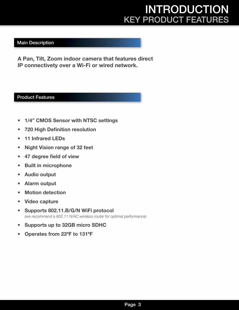
A Pan, Tilt, Zoom indoor camera that features direct IP connectivety over a Wi-Fi or wired network.
• 1/4” CMOS Sensor with NTSC settings
• 720 High Definition resolution
• 11 Infrared LEDs
• Night Vision range of 32 feet
• 47 degree field of view
• Built in microphone
• Audio output
• Alarm output
• Motion detection
• Video capture
• Supports 802.11.B/G/N WiFi protocol (we recommend a 802.11 N/AC wireless router for optimal performance)
• Supports up to 32GB micro SDHC
• Operates from 23ºF to 131ºF
Main Description
Product Features

Page 4
INTRODUCTIONTABLE OF CONTENTS
Section DeScription page #
1 Introduction 2-32 Safety 5
3Product Overview 6-7What is in the Box 6
Features and Setup 7
4 Program Function 8-9Menus 8-9
5Remote Viewing 10-11Setup 10
Smartphone Apps 11
6Program Functions 12Motion Recording 12
Alarms 13
7
Program Settings 14-21System & Video 14
Network & Alarms 15
Camera Properties 16
Devices Settings 17
Playback 18
Playback 19
Device Log 20
Help & Notifications 21
8Appendix 22-23Troubleshooting 22
Warranty 23
Page 5
SAFETYCAUTION STATEMENTS
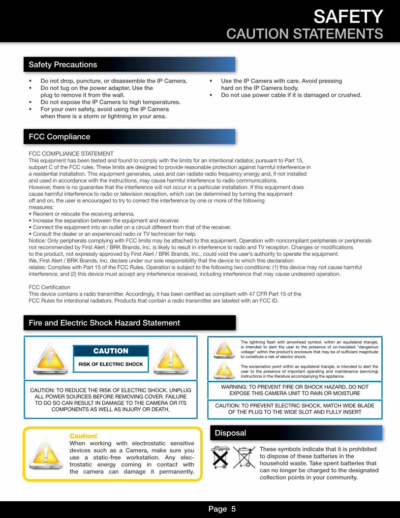
Safety Precautions
Safety Precautions
• Do not drop, puncture, or disassemble the IP Camera.• Do not tug on the power adapter. Use the
plug to remove it from the wall.• Do not expose the IP Camera to high temperatures. • For your own safety, avoid using the IP Camera
when there is a storm or lightning in your area.
• Use the IP Camera with care. Avoid pressing hard on the IP Camera body.
• Do not use power cable if it is damaged or crushed.
FCC COMPLIANCE STATEMENTThis equipment has been tested and found to comply with the limits for an intentional radiator, pursuant to Part 15, subpart C of the FCC rules. These limits are designed to provide reasonable protection against harmful interference in a residential installation. This equipment generates, uses and can radiate radio frequency energy and, if not installed and used in accordance with the instructions, may cause harmful interference to radio communications.However, there is no guarantee that the interference will not occur in a particular installation. If this equipment does cause harmful interference to radio or television reception, which can be determined by turning the equipment off and on, the user is encouraged to try to correct the interference by one or more of the followingmeasures:• Reorient or relocate the receiving antenna.• Increase the separation between the equipment and receiver.• Connect the equipment into an outlet on a circuit different from that of the receiver.• Consult the dealer or an experienced radio or TV technician for help.Notice: Only peripherals complying with FCC limits may be attached to this equipment. Operation with noncompliant peripherals or peripherals not recommended by First Alert / BRK Brands, Inc. is likely to result in interference to radio and TV reception. Changes or modifications to the product, not expressly approved by First Alert / BRK Brands, Inc., could void the user’s authority to operate the equipment.We, First Alert / BRK Brands, Inc. declare under our sole responsibility that the device to which this declarationrelates: Complies with Part 15 of the FCC Rules. Operation is subject to the following two conditions: (1) this device may not cause harmful interference, and (2) this device must accept any interference received, including interference that may cause undesired operation.
FCC CertificationThis device contains a radio transmitter. Accordingly, it has been certified as compliant with 47 CFR Part 15 of the FCC Rules for intentional radiators. Products that contain a radio transmitter are labeled with an FCC ID.
FCC Compliance
These symbols indicate that it is prohibited to dispose of these batteries in the household waste. Take spent batteries that can no longer be charged to the designated collection points in your community.
Disposal
Fire and Electric Shock Hazard Statement
CAUTION: TO REDUCE THE RISK OF ELECTRIC SHOCK. UNPLUG ALL POWER SOURCES BEFORE REMOVING COVER. FAILURE TO DO SO CAN RESULT IN DAMAGE TO THE CAMERA OR ITS
COMPONENTS AS WELL AS INJURY OR DEATH.
CAUTION
RISK OF ELECTRIC SHOCK
The lightning flash with arrowhead symbol, within an equilateral triangle, is intended to alert the user to the presence of un-insulated “dangerous voltage” within the product’s enclosure that may be of sufficient magnitude to constitute a risk of electric shock.
The exclamation point within an equilateral triangle, is intended to alert the user to the presence of important operating and maintenance (servicing) instructions in the literature accompanying the appliance.
WARNING: TO PREVENT FIRE OR SHOCK HAZARD, DO NOT EXPOSE THIS CAMERA UNIT TO RAIN OR MOISTURE
CAUTION: TO PREVENT ELECTRIC SHOCK, MATCH WIDE BLADE OF THE PLUG TO THE WIDE SLOT AND FULLY INSERT
Caution!When working with electrostatic sensitive devices such as a Camera, make sure you use a static-free workstation. Any elec-trostatic energy coming in contact with the camera can damage it permanently.
Page 6
PRODUCT OVERVIEWPACKAGE CONTENTS
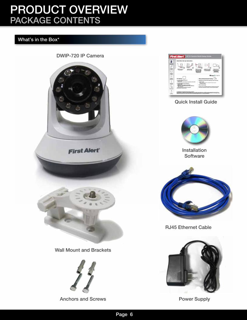
What,s in the Box*
DWIP-720 IP Camera
InstallationSoftware
RJ45 Ethernet Cable
Quick Install Guide
Power SupplyAnchors and Screws
Wall Mount and Brackets
Page 7
PRODUCT OVERVIEWFEATURES & SETUP
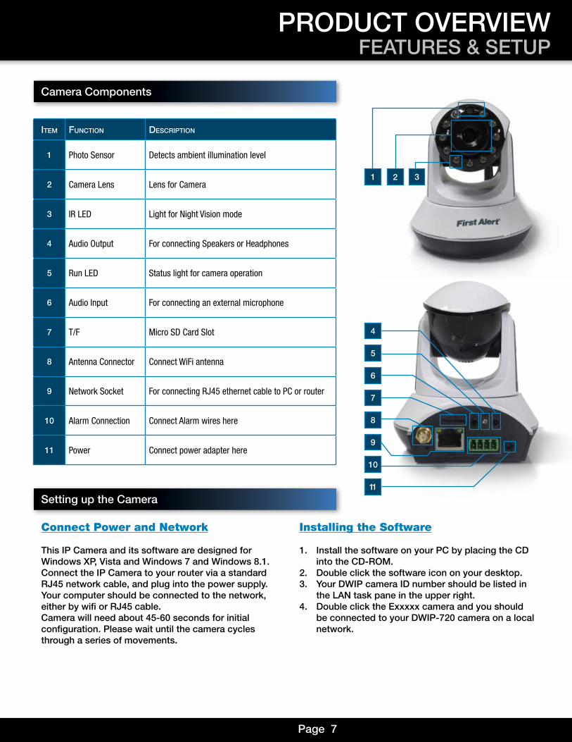
Camera Components
item Function DeScription
1 Photo Sensor Detects ambient illumination level
2 Camera Lens Lens for Camera
3 IR LED Light for Night Vision mode
4 Audio Output For connecting Speakers or Headphones
5 Run LED Status light for camera operation
6 Audio Input For connecting an external microphone
7 T/F Micro SD Card Slot
8 Antenna Connector Connect WiFi antenna
9 Network Socket For connecting RJ45 ethernet cable to PC or router
10 Alarm Connection Connect Alarm wires here
11 Power Connect power adapter here
1
4
6
8
10
11
5
7
9
2 3
Setting up the Camera
Connect Power and Network
This IP Camera and its software are designed forWindows XP, Vista and Windows 7 and Windows 8.1.Connect the IP Camera to your router via a standardRJ45 network cable, and plug into the power supply.Your computer should be connected to the network, either by wifi or RJ45 cable.Camera will need about 45-60 seconds for initialconfiguration. Please wait until the camera cyclesthrough a series of movements.
Installing the Software
1. Install the software on your PC by placing the CD into the CD-ROM.
2. Double click the software icon on your desktop.3. Your DWIP camera ID number should be listed in
the LAN task pane in the upper right. 4. Double click the Exxxxx camera and you should
be connected to your DWIP-720 camera on a local network.
Page 8
PROGRAM FUNCTIONSMENUS
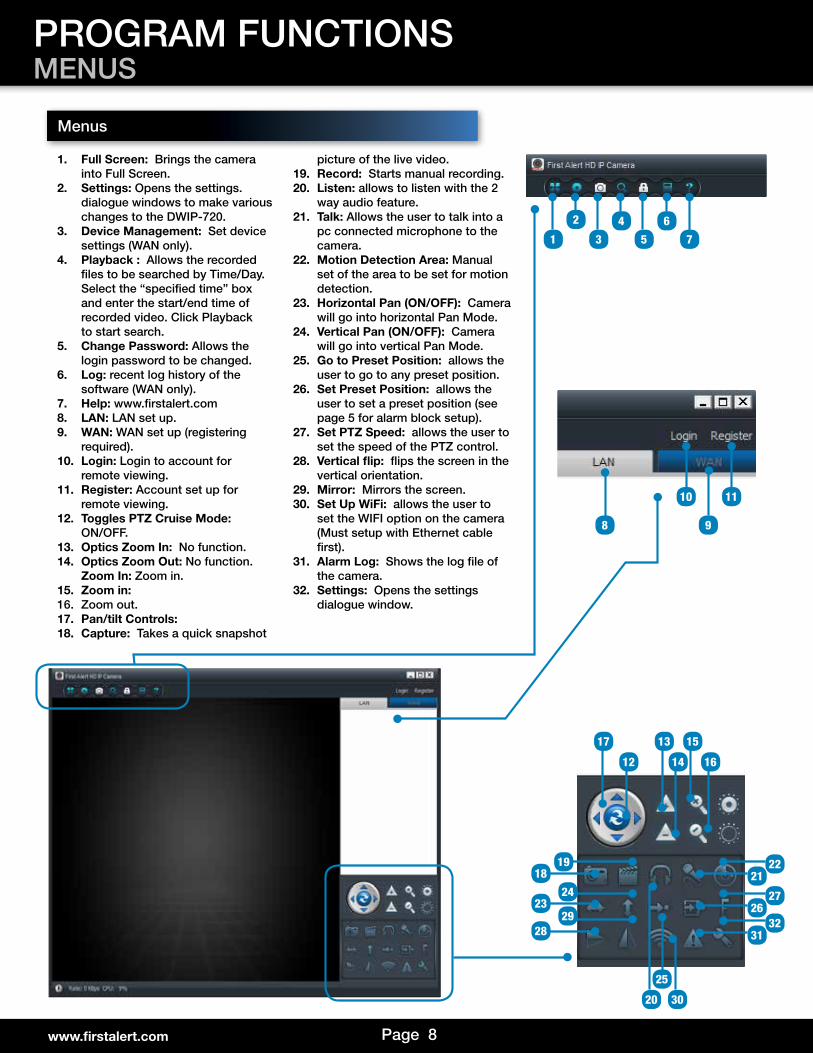
1. Full Screen: Brings the camera into Full Screen.
2. Settings: Opens the settings. dialogue windows to make various changes to the DWIP-720.
3. Device Management: Set device settings (WAN only).
4. Playback : Allows the recorded files to be searched by Time/Day. Select the “specified time” box and enter the start/end time of recorded video. Click Playback to start search.
5. Change Password: Allows the login password to be changed.
6. Log: recent log history of the software (WAN only).
7. Help: www.firstalert.com8. LAN: LAN set up.9. WAN: WAN set up (registering
required).10. Login: Login to account for
remote viewing.11. Register: Account set up for
remote viewing.12. Toggles PTZ Cruise Mode:
ON/OFF.13. Optics Zoom In: No function.14. Optics Zoom Out: No function.
Zoom In: Zoom in.15. Zoom in: 16. Zoom out.17. Pan/tilt Controls:18. Capture: Takes a quick snapshot
picture of the live video.19. Record: Starts manual recording.20. Listen: allows to listen with the 2
way audio feature.21. Talk: Allows the user to talk into a
pc connected microphone to the camera.
22. Motion Detection Area: Manual set of the area to be set for motion detection.
23. Horizontal Pan (ON/OFF): Camera will go into horizontal Pan Mode.
24. Vertical Pan (ON/OFF): Camera will go into vertical Pan Mode.
25. Go to Preset Position: allows the user to go to any preset position.
26. Set Preset Position: allows the user to set a preset position (see page 5 for alarm block setup).
27. Set PTZ Speed: allows the user to set the speed of the PTZ control.
28. Vertical flip: flips the screen in the vertical orientation.
29. Mirror: Mirrors the screen.30. Set Up WiFi: allows the user to
set the WIFI option on the camera (Must setup with Ethernet cable first).
31. Alarm Log: Shows the log file of the camera.
32. Settings: Opens the settings dialogue window.
1 3 5 7
10
2219
27
32
24
29
21
26
31
20 30
25
9
2 4 6
8
www.firstalert.com
Menus
11
18
23
28
1317 15
1412 16
Page 9
Menus (continued)
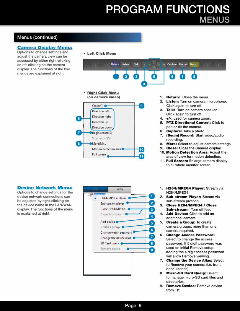
Camera Display Menu:Options to change settings and adjust the camera view can be accessed by either right-clicking or left-clicking on the camera display. The functions of the two menus are explained at right.
Device Network Menu:Options to change settings for the device network connections can be adjusted by right-clicking on the device name in the LAN/WAN display. The functions of the menu is explained at right.
• Right Click Menu (on camera video)
• Left Click Menu
PROGRAM FUNCTIONSMENUS
1. Return: Close the menu.2. Listen: Turn on camera microphone. Click again to turn off.3. Talk: Turn on camera speaker. Click again to turn off.4. +/-: used for camera zoom.5. PTZ Directional Control: Click to pan or tilt the camera.6. Capture: Take a photo.7. (Begin) Record: Start video/audio recording.8. More: Select to adjust camera settings.9. Close: Close the Camera display. 10. Motion Detection Area: Adjust the area of view for motion detection. 11. Full Screen: Enlarge camera display to fill whole monitor screen.
1 3 5 72
4
6 8
5
7
8
10
9
11
1
3
6
2
7
9
8
1. H264/MPEG4 Player: Stream via H264/MPEG4.2. Sub-stream Player: Stream via sub-stream protocol.3. Close H264/MPEG4 / Close Sub-stream: Turn off feed.4. Add Device: Click to add an additional camera.5. Create a Group: To create camera groups, more than one camera required.6. Change Access Password: Select to change the access password. If 5 digit password was used on initial Remove setup. Adding the 4 digit access password will allow Remove viewing.7. Change the Device Alias: Select to Remove your camera (i.e. front door, kitchen). 8. Micro-SD Card Query: Select to manage micro-SD card files and directories.9. Remove Device: Remove device from list.
4
5
Page 10
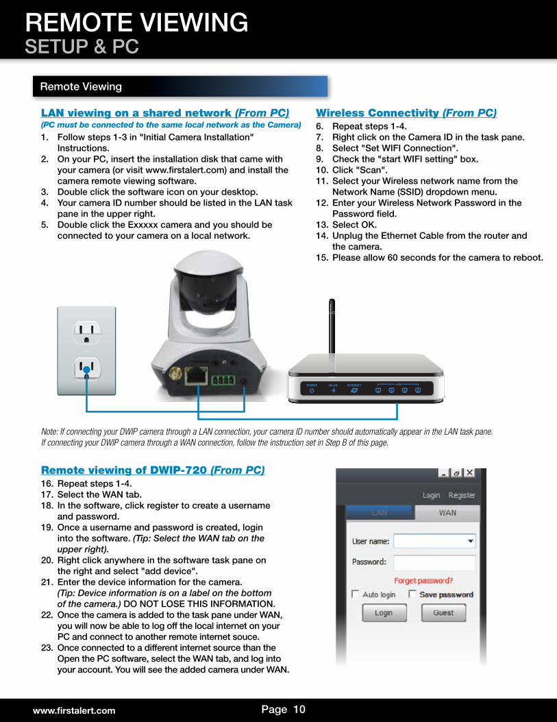
1. Follow steps 1-3 in "Initial Camera Installation" Instructions.
2. On your PC, insert the installation disk that came with your camera (or visit www.firstalert.com) and install the camera remote viewing software.
3. Double click the software icon on your desktop.4. Your camera ID number should be listed in the LAN task
pane in the upper right.5. Double click the Exxxxx camera and you should be
connected to your camera on a local network.
16. Repeat steps 1-4.17. Select the WAN tab.18. In the software, click register to create a username
and password.19. Once a username and password is created, login
into the software. (Tip: Select the WAN tab on the upper right).
20. Right click anywhere in the software task pane on the right and select "add device".
21. Enter the device information for the camera. (Tip: Device information is on a label on the bottom of the camera.) DO NOT LOSE THIS INFORMATION.
22. Once the camera is added to the task pane under WAN, you will now be able to log off the local internet on your PC and connect to another remote internet souce.
23. Once connected to a different internet source than the Open the PC software, select the WAN tab, and log into your account. You will see the added camera under WAN.
6. Repeat steps 1-4.7. Right click on the Camera ID in the task pane.8. Select "Set WIFI Connection".9. Check the "start WIFI setting" box.10. Click "Scan".11. Select your Wireless network name from the
Network Name (SSID) dropdown menu.12. Enter your Wireless Network Password in the
Password field.13. Select OK.14. Unplug the Ethernet Cable from the router and
the camera.15. Please allow 60 seconds for the camera to reboot.
LAN viewing on a shared network (From PC)(PC must be connected to the same local network as the Camera)
Wireless Connectivity (From PC)
Remote viewing of DWIP-720 (From PC)
Note: If connecting your DWIP camera through a LAN connection, your camera ID number should automatically appear in the LAN task pane. If connecting your DWIP camera through a WAN connection, follow the instruction set in Step B of this page.
Remote Viewing
REMOTE VIEWINGSETUP & PC
www.firstalert.com
Page 11
REMOTE VIEWINGSMARTPHONE APPS
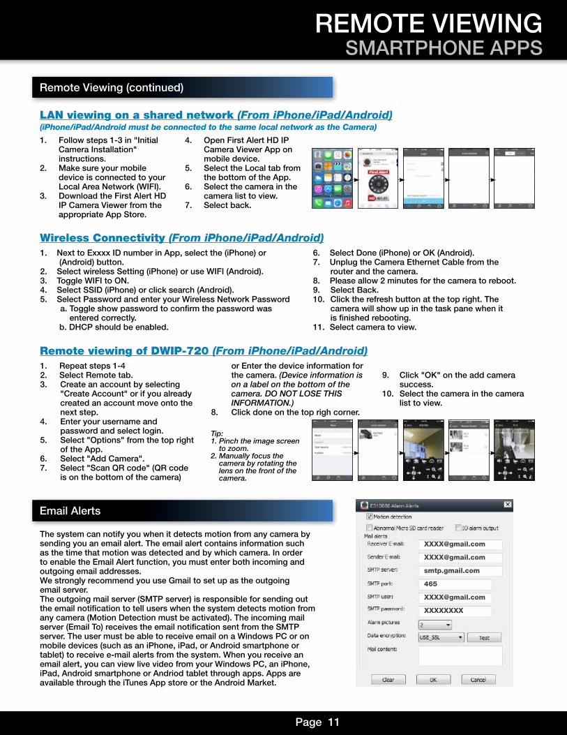
1. Follow steps 1-3 in "Initial Camera Installation" instructions.
2. Make sure your mobile device is connected to your Local Area Network (WIFI).
3. Download the First Alert HD IP Camera Viewer from the appropriate App Store.
4. Open First Alert HD IP Camera Viewer App on mobile device.
5. Select the Local tab from the bottom of the App.
6. Select the camera in the camera list to view.
7. Select back.
1. Repeat steps 1-4 2. Select Remote tab.3. Create an account by selecting "Create Account" or if you already created an account move onto the next step.4. Enter your username and password and select login.5. Select "Options" from the top right of the App.6. Select "Add Camera".7. Select "Scan QR code" (QR code is on the bottom of the camera)
or Enter the device information for the camera. (Device information is on a label on the bottom of the camera. DO NOT LOSE THIS INFORMATION.)8. Click done on the top righ corner.
9. Click "OK" on the add camera success.10. Select the camera in the camera list to view.
1. Next to Exxxx ID number in App, select the (iPhone) or (Android) button.
2. Select wireless Setting (iPhone) or use WIFI (Android).3. Toggle WIFI to ON.4. Select SSID (iPhone) or click search (Android).5. Select Password and enter your Wireless Network Password a. Toggle show password to confirm the password was entered correctly. b. DHCP should be enabled.
6. Select Done (iPhone) or OK (Android).7. Unplug the Camera Ethernet Cable from the router and the camera.8. Please allow 2 minutes for the camera to reboot.9. Select Back.10. Click the refresh button at the top right. The
camera will show up in the task pane when it is finished rebooting.
11. Select camera to view.
LAN viewing on a shared network (From iPhone/iPad/Android)(iPhone/iPad/Android must be connected to the same local network as the Camera)
Remote viewing of DWIP-720 (From iPhone/iPad/Android)
Wireless Connectivity (From iPhone/iPad/Android)
Remote Viewing (continued)
Email Alerts
The system can notify you when it detects motion from any camera by sending you an email alert. The email alert contains information such as the time that motion was detected and by which camera. In order to enable the Email Alert function, you must enter both incoming andoutgoing email addresses.We strongly recommend you use Gmail to set up as the outgoing email server.The outgoing mail server (SMTP server) is responsible for sending out the email notification to tell users when the system detects motion from any camera (Motion Detection must be activated). The incoming mail server (Email To) receives the email notification sent from the SMTP server. The user must be able to receive email on a Windows PC or on mobile devices (such as an iPhone, iPad, or Android smartphone or tablet) to receive e-mail alerts from the system. When you receive an email alert, you can view live video from your Windows PC, an iPhone, iPad, Android smartphone or Andriod tablet through apps. Apps are available through the iTunes App store or the Android Market.
smtp.gmail.com
465
XXXXXXXX
Tip:1. Pinch the image screen to zoom.2. Manually focus the camera by rotating the lens on the front of the camera.
Page 12
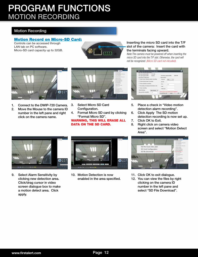
1. Connect to the DWIP-720 Camera.2. Move the Mouse to the camera ID
number in the left pane and right click on the camera name.
3. Select Micro SD Card Configuration.
4. Format Micro SD card by clicking “Format Micro SD”.
WARNING, THIS WILL ERASE ALL DATA ON THE SD CARD.
5. Place a check in “Video motion detection alarm recording”.
6. Click Apply The SD motion detection recording is now set up.
7. Click OK to Exit.8. Right click on camera video
screen and select “Motion Detect Area”.
9. Select Alarm Sensitivity by clicking new detection area. Click/drag cursor in video screen dialogue box to make a motion detect area. Click apply.
10. Motion Detection is now enabled in the area specified.
11. Click OK to exit dialogue.12. You can view the files by right
clicking on the camera ID number in the left pane and select “SD File Download”.
Inserting the micro SD card into the T/F slot of the camera: Insert the card with the terminals facing upward.Note:The camera must be powered off when inserting the micro SD card into the T/F slot. Otherwise, the card will not be recognized. (Micro SD card not inlcuded).
PROGRAM FUNCTIONSMOTION RECORDING
Motion Recording
www.firstalert.com
Motion Record on Micro-SD Card:Controls can be accessed through LAN tab on PC software.Micro-SD card capacity up to 32GB.
Page 13
Alarm Inputs:Alarm inputs are switches that activate when a door, window, cabinet etc. is opened or accessed. For example, you might want to only have the camera record when someone opens a tool cabinet or when a door opens vs. recording when motion occurs around those areas. There may be people moving by those areas frequently but you are only concerned about when those areas are accessed. This saves storage space and makes it easier to find an event that was recorded.External Sensor Alarm Pattern:5 Seconds ON 3 Seconds OFF repeat...Motion Alarm Pattern:2 seconds on
NOTE: The Maximum output current is 300mA and the Maximum Output voltage is 5.0V.
NOTE: When using external sensor you must program the view location on program 2. When external sensor is tripped the camera will move to the preset location.
To Connect an external Sensor to the DWIP-720Connect GND (-) of Sensor to ALARM IN 4(-) of the DWIP-720.Connect NO (+) of Sensor to ALARM IN 3(+) of the DWIP-720.
To Connect an external Alarm to the DWIP-720Alarm output is used to activate an external device such as a horn or LED or relay after an alarm is triggered. To configure alarm outputs, connect the external device to the out connections on the alarm block as required by the device.Connect (-) of ALARM to ALARM IN 2(+) of the DWIP-720.Connect (+) of ALARM to ALARM IN 1(-) of the DWIP-720
Alarm Block FunctionalityPreset Positions must be configured for the Alarm Block features through the software. When an Alarm is detected, the camera will enter in the default Alarm position. To change this default Alarm position you must first set the camera’s position, click “Set Preset Position” in the software and choose the Alarm Block. There are a total of 8 preset postitions that can be created for the Alarm Block.
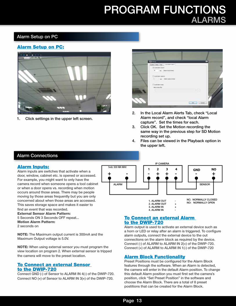
1. Click settings in the upper left screen.2. In the Local Alarm Alerts Tab, check “Local
Alarm record”, and check “local Alarm capture”. Set the times for each.
3. Click OK. Set the Motion recording the same way in the previous step for SD Motion recording set up.
4. Files can be viewed in the Playback option in the upper left.
PROGRAM FUNCTIONSALARMS
Alarm Setup on PC
Alarm Setup on PC:
1 2 3 4-- - -+ + ++
1. ALARM OUT -2. ALARM OUT +3. ALARM IN +4. ALARM IN -
ALARM
IP CAMERA
SENSOR
NC: NORMALLY CLOSEDNO: NORMALLY OPEN
NOGND5vdc 300 MA MAX
Alarm Connections
Page 14
PROGRAM SETTINGSSYSTEM & VIDEO
www.firstalert.com
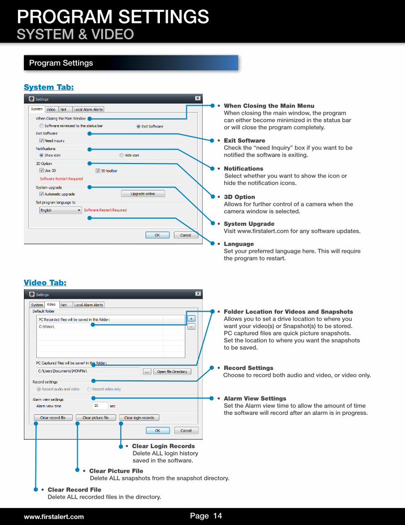
Program Settings
• When Closing the Main Menu When closing the main window, the program can either become minimized in the status bar or will close the program completely.
• Exit Software Check the “need Inquiry” box if you want to be notified the software is exiting.
• NotificationsSelect whether you want to show the icon or
hide the notification icons.
• 3D Option Allows for further control of a camera when the camera window is selected.
• System Upgrade Visit www.firstalert.com for any software updates.
• Language Set your preferred language here. This will require the program to restart.
• Folder Location for Videos and Snapshots Allows you to set a drive location to where you want your video(s) or Snapshot(s) to be stored. PC captured files are quick picture snapshots. Set the location to where you want the snapshots to be saved.
• Record Settings Choose to record both audio and video, or video only.
• Alarm View Settings Set the Alarm view time to allow the amount of time the software will record after an alarm is in progress.
• Clear Record File Delete ALL recorded files in the directory.
• Clear Picture File Delete ALL snapshots from the snapshot directory.
• Clear Login Records Delete ALL login history saved in the software.
System Tab:
Video Tab:
Page 15
PROGRAM SETTINGSNETWORK & ALARMS
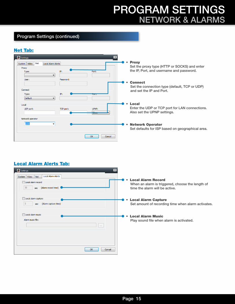
• Local Alarm Record When an alarm is triggered, choose the length of time the alarm will be active.
• Local Alarm Capture Set amount of recording time when alarm activates.
• Local Alarm Music Play sound file when alarm is activated.
• Proxy Set the proxy type (HTTP or SOCKS) and enter the IP, Port, and username and password.
• Connect Set the connection type (default, TCP or UDP) and set the IP and Port.
• Local Enter the UDP or TCP port for LAN connections. Also set the UPNP settings.
• Network Operator Set defaults for ISP based on geographical area.
Net Tab:
Local Alarm Alerts Tab:
Program Settings (continued)
Page 16www.firstalert.com
PROGRAM SETTINGSCAMERA PROPERTIES
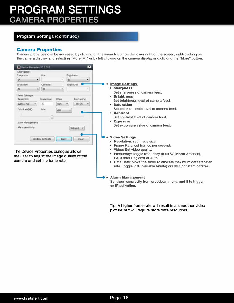
Camera PropertiesCamera properties can be accessed by clicking on the wrench icon on the lower right of the screen, right-clicking onthe camera display, and selecting “More (M)” or by left clicking on the camera display and clicking the “More” button.
Program Settings (continued)
The Device Properties dialogue allows the user to adjust the image quality of the camera and set the fame rate.
Tip: A higher frame rate will result in a smoother video picture but will require more data resources.
• Image Settings • Sharpness Set sharpness of camera feed.• Brightness Set brightness level of camera feed.• Saturation Set color saturatio level of camera feed.• Contrast Set contrast level of camera feed.• Exposure Set exporsure value of camera feed.
• Video Settings• Resolution: set image size.• Frame Rate: set frames per second.• Video: Set video quality.• Frequency: Toggle frequency to NTSC (North America), PAL(Other Regions) or Auto.• Data Rate: Move the slider to allocate maximum data transfer rate. Toggle VBR (variable bitrate) or CBR (constant bitrate).
• Alarm Management Set alarm sensitivity from dropdown menu, and if to trigger on IR activation.
Page 17
PROGRAM SETTINGSDEVICE SETTINGS
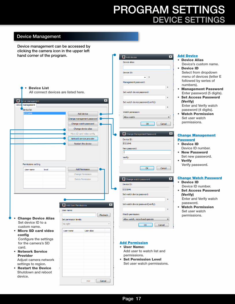
Device management can be accessed byclicking the camera icon in the upper left hand corner of the program.
Device Management
• Device List All connect devices are listed here.
Add Device• Device Alias Device’s custom name.
• Device ID Select from dropdown menu of devices (letter E followed by series of numbers).
• Management PasswordEnter password (5 digits).
• Set Access Password (Verify)
Enter and Verify watch password (4 digits).
• Watch Permission Set user watch permissions.
Change ManagementPassword• Device ID Device ID number.
• New Password Set new password.
• Verify Verify password.
Change Watch Password• Device ID Device ID number.
• Set Access Password (Verify)
Enter and Verify watch password.
• Watch Permission Set user watch permissions.
• Change Device Alias Set device ID to a custom name.
• Micro SD card video config
Configure the settings for the camera’s SD card.
• Network Service Provider
Adjust camera network settings to region.
• Restart the Device Shutdown and reboot device.
Add Permission• User Name: Add user to watch list and permissions.
• Set Permission Level Set user watch permissions.
Page 18www.firstalert.com
Playback
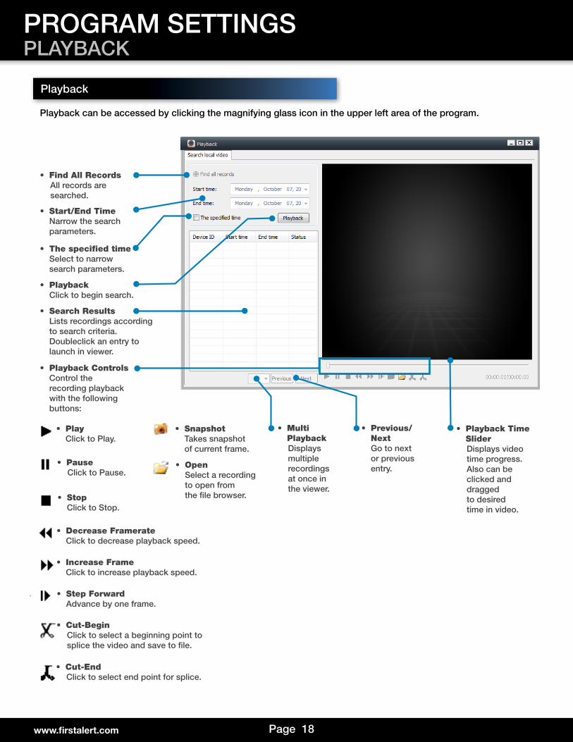
• Find All Records All records are searched.
• Start/End Time Narrow the search parameters.
• The specified time Select to narrow search parameters.
• Search Results Lists recordings according to search criteria. Doubleclick an entry to launch in viewer.
• Playback Controls Control the recording playback with the following buttons:
• Play Click to Play.
• Pause Click to Pause.
• Stop Click to Stop.
• Decrease Framerate Click to decrease playback speed.
• Increase Frame Click to increase playback speed.
• Step Forward Advance by one frame.
• Snapshot Takes snapshot of current frame.
• Open Select a recording to open from the file browser.
• Cut-Begin Click to select a beginning point to splice the video and save to file.
• Cut-End Click to select end point for splice.
PROGRAM SETTINGSPLAYBACK
• Playback Click to begin search.
• Playback Time Slider
Displays video time progress. Also can be clicked and dragged to desired time in video.
• Multi Playback
Displays multiple recordings at once in the viewer.
• Previous/Next
Go to next or previous entry.
Playback can be accessed by clicking the magnifying glass icon in the upper left area of the program.
Page 19
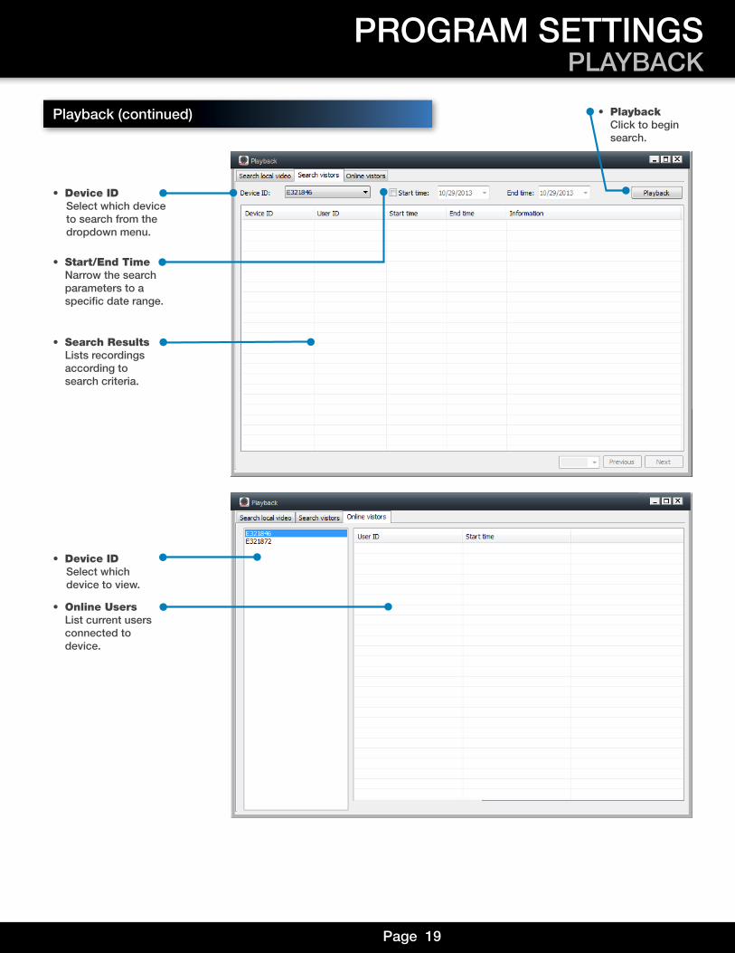
• Device ID Select which device to search from the dropdown menu.
• Start/End Time Narrow the search parameters to a specific date range.
• Search Results Lists recordings according to search criteria.
• Online Users List current users connected to device.
• Device ID Select which device to view.
PROGRAM SETTINGSPLAYBACK
Playback (continued) • Playback Click to begin search.
Page 20www.firstalert.com
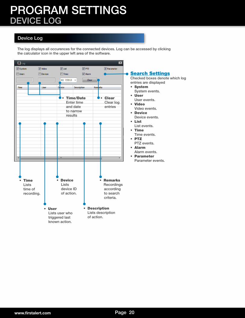
The log displays all occurences for the connected devices. Log can be accessed by clickingthe calculator icon in the upper left area of the software.
Device Log
• TimeLists
time of recording.
• User Lists user who triggered last known action.
• Device Lists device ID of action.
• Description Lists description of action.
PROGRAM SETTINGSDEVICE LOG
Search SettingsChecked boxes denote which log entries are displayed• System
System events.• User
User events.• Video
Video events.• Device
Device events.• List
List events.• Time Time events.
• PTZPTZ events.
• AlarmAlarm events.
• ParameterParameter events.
• Remarks Recordings according to search criteria.
• Clear Clear log entries
• Time/Date Enter time and date to narrow results
Page 21
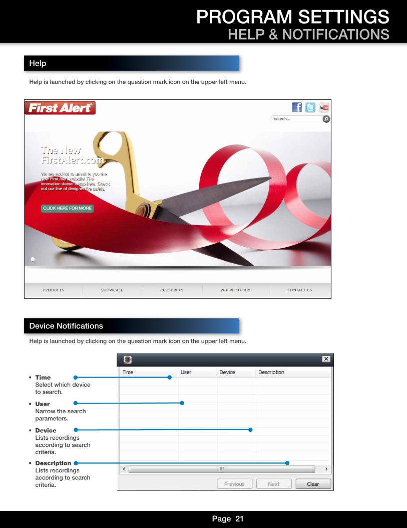
Help
Device Notifications
Help is launched by clicking on the question mark icon on the upper left menu.
• Time Select which device to search.
• User Narrow the search parameters.
• Device Lists recordings according to search criteria.
• Description Lists recordings according to search criteria.
PROGRAM SETTINGSHELP & NOTIFICATIONS
Help is launched by clicking on the question mark icon on the upper left menu.
Page 22
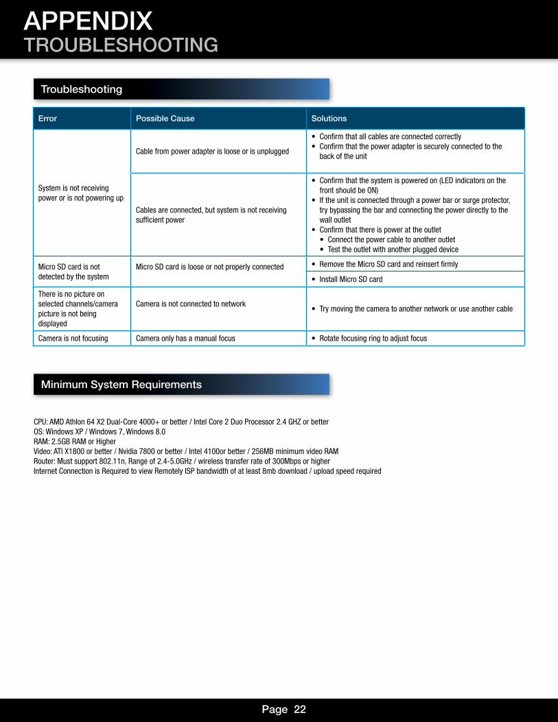
Error Possible Cause Solutions
System is not receiving power or is not powering up
Cable from power adapter is loose or is unplugged
• Confirm that all cables are connected correctly• Confirm that the power adapter is securely connected to the
back of the unit
Cables are connected, but system is not receiving sufficient power
• Confirm that the system is powered on (LED indicators on the front should be ON)
• If the unit is connected through a power bar or surge protector, try bypassing the bar and connecting the power directly to the wall outlet
• Confirm that there is power at the outlet• Connect the power cable to another outlet• Test the outlet with another plugged device
Micro SD card is not detected by the system
Micro SD card is loose or not properly connected • Remove the Micro SD card and reinsert firmly
• Install Micro SD card
There is no picture on selected channels/camera picture is not being displayed
Camera is not connected to network• Try moving the camera to another network or use another cable
Camera is not focusing Camera only has a manual focus • Rotate focusing ring to adjust focus
Troubleshooting
Minimum System Requirements
APPENDIXTROUBLESHOOTING
CPU: AMD Athlon 64 X2 Dual-Core 4000+ or better / Intel Core 2 Duo Processor 2.4 GHZ or betterOS: Windows XP / Windows 7, Windows 8.0RAM: 2.5GB RAM or HigherVideo: ATI X1800 or better / Nvidia 7800 or better / Intel 4100or better / 256MB minimum video RAMRouter: Must support 802.11n, Range of 2.4-5.0GHz / wireless transfer rate of 300Mbps or higherInternet Connection is Required to view Remotely ISP bandwidth of at least 8mb download / upload speed required
Page 23
Warranty
PRODUCT LIMITED WARRANTYBRK Brands, Inc., (“BRK”) the maker of First Alert® brand products warrants that for a period of one year from the date of purchase (the “Warranty Period”), this product will be free from defects in material and workmanship. BRK, at its sole option, will repair or replace this product or any component of the product found to be defective during the Warranty Period. Replacement or repair will be made with a new or remanufactured product or component. If the product is no longer available, replacement may be made with a similar product of equal or greater value. This is your exclusive warranty.This warranty is valid for the original retail purchaser only from the date of initial retail purchase and is not transferable. In order to obtain warranty service, you must keep the original sales receipt and proof of purchase in the form of the UPC code from the package. BRK dealers, service centers, or retail stores selling BRK products do not have the right to alter, modify or any way change the terms and conditions of this warranty. WARRANTY EXCLUSIONSParts and Labor: 1 year limited (warranted parts do not include bulbs, LEDs, and batteries)This warranty does not apply to bulbs, LEDs, and batteries supplied with or forming part of the product.This warranty is invalidated if non- BRK accessories are or have been used in or in connection with the product or in any modification or repair is made to the product.This warranty does not apply to defects or damages arising by use of the product in other than normal (including normal atmospheric, moisture and humidity) conditions or by installation or use of the product other than in strict accordance with the instructions contained in the product owner’s manual.This warranty does not apply to defects in or damages to the product caused by (i) negligent use of the product, (ii) misuse, abuse, neglect, alteration, repair or improper installation of the product, (iii) electrical short circuits or transients, (iv) usage not in accordance with product installation, (v) use of replacement parts not supplied by BRK, (vi) improper product maintenance, or (vii) accident, fire, flood or other Acts of God.This warranty does not cover the performance or functionality of any computer software included in the package with the product. BRK makes no warranty that the software provided with the product will function without interruption or otherwise be free of anomalies, errors, or “Bugs.” This warranty does not cover any costs relating to removal or replacement of any product or software installed on your computer.BRK reserves the right to make changes in design or to make additions to or improvements in its products without incurring any obligations to modify any product which has already been manufactured. BRK will make every effort to provide updates and fixes to its software via its website. This warranty does not cover any alteration or damage to any other software that may be or may become resident on the users system as a result of installing the software provided. This warranty is in lieu of other warranties, expressed or implied, and BRK neither assumes nor authorizes any person to assume for it any other obligation or liability in connection with the sale or service of the product. In no event shall BRK be liable for any special or consequential damages arising from the use of the product or arising from the malfunctioning or non-functioning of the product, or for any delay in the performance of this warranty due to any cause beyond its control.BRK does not make any claims or warranties of any kind whatsoever regarding the product’s potential, ability, or effectiveness to prevent, minimize, or in any way affect personal or property damage or injury. BRK is not responsible for any personal damage, loss, or theft related to the product or to its use for any harm, whether physical or mental related thereto. Any and all claims or statements, whether written or verbal, by salespeople, retailers, dealers, or distributors to the contrary are not authorized by BRK, and do not affect this provision of this warranty.BRK’s responsibility under this, or any other warranty, implied or expressed, is limited to repair, replacement or refund, as set forth above. These remedies are the sole and exclusive remedies for any breach of warranty. BRK is not responsible for direct, special, incidental, or consequential damages resulting from any breach of warranty or under any other legal theory including but not limited to, loss profits, downtime, goodwill, damage to or replacement of equipment and property and any costs of recovering, reprogramming or reproducing any program or data stored in or used with a system containing the product accompanying software.BRK does not warrant the software will operate with any other software except that which is indicated. BRK cannot be responsible for characteristics of their party hardware or software which may effect the operation of the software included.Except to the extent prohibited by applicable law, any implied warranty of merchantability or fitness for a particular purpose is limited in duration to the duration of the above Warranty Period. Some states, provinces, or jurisdictions do not allow the exclusion or limitation of incidental or consequential damages or limitations on how long an implied warranty lasts, so the above limitations or exclusion may not apply to you. This warranty gives you specific legal rights, and you may also have other rights that vary from state to state, or province to province, or jurisdiction to jurisdiction.OBTAINING SERVICEIf service is required, do not return the product to your place of purchase. In order to obtain warranty service, contact the Consumer Affairs Division at 1-800-323-9005, 7:30 a.m. – 5:00 a.m. Central Standard Time, Monday through Friday. To assist us in serving you, please have the model number and date of purchase available when calling.After contacting the Consumer Affairs Division and it is determined that the product should be returned for Warranty Service, please mail the product to: BRK Brands, Inc., 3901 Liberty Street Road, Aurora, IL 60504-8122.
APPENDIXWARRANTY

©2014 BRK Brands, Inc. a Jarden Corporation Company (NYSE:JAH)3901 Liberty Street Road, Aurora, IL 60504-8122 Phone: 630-851-7330 Tech Services: 800-323-9005www.firstalert.comM08-0463-000