user’s model us1000 manual digital indicating … 5d1a01-02e iii notice this instruction manual...
TRANSCRIPT

User’sManual
Model US1000Digital Indicating ControllerFunctions
IM 5D1A01-02E
IM 5D1A01-02E2nd Edition


iIM 5D1A01-02E
FD No. IM 5D1A01-02E2nd Edition: Jun. 2004 (KP)AllRights Reserved. Copyright © 1998. Yokogawa Electric Corporation
IntroductionThis instruction manual describes the functions of the US1000 Digital Indicating Controller in detail.Read this manual together with the separate instruction manual for the “US1000 Digital IndicatingController” when setting up your US1000 controller.
Contents of This ManualThis manual contains the following:
• Examples of the US1000’s applications• Description of each controller mode (US mode)• Description of all the parameters
Intended ReadersThis manual is intended for personnel in charge of instrumentation and setup of the controller.
Related DocumentsThe following are the documents related to the US1000 Digital Indicating Controller. Read them asnecessary. The codes enclosed in parentheses are their document numbers.
• US1000 Digital Indicating Controller (IM 5D1A01-01E)This manual introduces the basic functions and provides instructions for the general operation of theUS1000 controller.
• US1000 Digital Indicating Controller Communication Functions (IM 5D1A01-10E)Manual for using the US1000 communication function. Supplied with models having the optionalcommunication function.
• LL1100 PC-based Parameters Setting Tool (IM 5G1A01-01E)Manual for setting US1000 parameters from a personal computer. Supplied with the LL1100 PC-based Parameters Setting Tool.
• LL1200 PC-based Custom Computation Building Tool (IM 5G1A11-01E)Operation manual for creating custom computations by the US1000 controller. This manual alsodescribes examples of custom computations. The LL1200 PC-based Custom Computation BuildingTool includes the LL1100 PC-based Parameters Setting Tool.
• LL1200 PC-based Custom Computation Building Tool Reference (IM 5G1A11-02E)This is the functions manual necessary for creating custom computations by the US1000 controller.This manual should be referred to in order to find out and understand what functions offered by theLL1200.

IM 5D1A01-02Eii
Documentation Conventions
SymbolicThe following symbolic are used in this manual.
WARNINGIndicates that operating the hardware or software in a particular manner may damage it or result in asystem failure.
NOTEDraws attention to information that is essential for understanding the operation and/or features of theproduct.
TIPGives additional information to complement the present topic and/or describe terms specific to thisdocument.
See Also Gives reference locations for further information on the topic.
Description of DisplaysSome of the representations of product displays shown in this manual may be exaggerated, simplified,or partially omitted for reasons of convenience when explaining them.

iiiIM 5D1A01-02E
Notice
This Instruction Manual(1) This manual should be passed on to the end user. Keep at least one extra copy of the manual in a
safe place.(2) Read this manual carefully to gain a thorough understanding of how to operate this product before
you start using it.(3) This manual is intended to describe the functions of this product. Yokogawa Electric Corporation
(hereinafter simply referred to as Yokogawa) does not guarantee that these functions are suited tothe particular purpose of the user.
(4) Under absolutely no circumstances may the contents of this manual, in part or in whole, betranscribed or copied without permission.
(5) The contents of this manual are subject to change without prior notice.(6) Every effort has been made to ensure accuracy in the preparation of this manual. Should any
errors or omissions come to your attention however, please contact your nearest Yokogawarepresentative or our sales office.
Protection, Safety, and Prohibition Against Unauthorized Modification(1) In order to protect the product and the system controlled by it against damage and ensure its safe
use, make certain that all of the instructions and precautions relating to safety contained in thisdocument are strictly adhered to. Yokogawa does not guarantee safety if products are not handledaccording to these instructions.
(2) The following safety symbols are used on the product and in this manual.
CAUTION
If this symbol is indicated on the product, the operator should refer to the explanation given in theinstruction manual in order to avoid personal injury or death to either themselves or other personnel,and/or damage to the instrument. The manual describes that the operator should exercise special careto avoid shock or other dangers that may result in injury or loss of life.
Protective ground terminal:
This symbol indicates that the terminal must be connected to ground prior to operating the equipment.
Function ground terminal:
This symbol indicates that the terminal must be connected to ground prior to operating the equipment.
(3) If protection/safety circuits are to be used for the product or the system controlled by it, theyshould be externally installed on the product.
(4) When you replace the parts or consumables of the product, only use those specified by Yokogawa .(5) Do not modify the product.

IM 5D1A01-02Eiv
Force Majeure(1) Yokogawa does not make any warranties regarding the product except those mentioned in the
WARRANTY that is provided separately.(2) Yokogawa assumes no liability to any party for any loss or damage, direct or indirect, caused by
the use or any unpredictable defect of the product.
WARNINGDo not change the setting of the following US1000 controller parameter.
[Setup parameter] - [Main menu: USMD] - [Submenu: TEST]Parameter: TST (Test mode)
This parameter is used to adjust a US1000 controller at the factory. If you change the setting of thisparameter, the US1000 controller may not operate normally.
CAUTIONOnly personnel with an understanding of the US1000 controller and custom computation functions arequalified to change the settings of the following parameters as necessary. Those using the US1000controller for the first time and those not knowledgeable about the custom computation function,should use the default values of the following parameters assigned to the controller.
[Setup parameter] - [Main menu: CONF] - [Submenu: DO and DI]All the parameters under the submenus above.
If you change the settings of these parameters, some of the functions assigned to each US1000controller mode (US mode) may not work.

vIM 5D1A01-02E
Contents
Introduction ........................................................................................................................... iDocumentation Conventions ............................................................................................... iiNotice .................................................................................................................................... iiiContents ................................................................................................................................ v
1. Examples of US1000 Applications............................................................................ 1-1
2. Controller Mode (US Mode) ..................................................................................... 2-1
2.1 Single-loop Control (US mode 1) ................................................................... 2-22.2 Cascade Primary-loop Control (US mode 2) ................................................. 2-82.3 Cascade Secondary-loop Control (US mode 3) ........................................... 2-102.4 Cascade Control (US mode 4) ...................................................................... 2-132.5 Loop Control for Backup (US mode 5) ........................................................ 2-162.6 Loop Control with PV Switching (US mode 6) ........................................... 2-192.7 Loop Control with PV Auto-selector (US mode 7) ..................................... 2-242.8 Loop Control with PV-hold Function (US mode 8) .................................... 2-282.9 Dual-loop Control (US mode 11) ................................................................. 2-322.10 Temperature and Humidity Control (US mode 12) ..................................... 2-342.11 Cascade Control with Two Universal Inputs (US mode 13) ....................... 2-362.12 Loop Control with PV Switching and Two Universal Inputs
(US mode 14) ................................................................................................ 2-392.13 Loop Control with PV Auto-selector and Two Universal Inputs
(US mode 15) ................................................................................................ 2-422.14 Custom Computation Control (US mode 21) ............................................... 2-45
3. Parameters .................................................................................................................. 3-1
3.1 Parameters that Determine the Action at Power-on and Power Recovery .... 3-23.2 Parameters for Analog Input ........................................................................... 3-3
3.2.1 Analog Input Type and Unit .................................................................... 3-33.2.2 Analog Input Range and PV Range ......................................................... 3-53.2.3 Decimal Point Position of Analog Input .................................................. 3-63.2.4 Display Scale of Analog Input ................................................................. 3-63.2.5 Analog Input Bias (Normally used at default) ......................................... 3-73.2.6 Analog Input Filter (Normally used at default) ....................................... 3-73.2.7 Square-root Extraction ............................................................................. 3-83.2.8 Action at a Burnout .................................................................................. 3-93.2.9 Reference Junction Compensation for Analog Input ............................... 3-9
3.3 Parameters for PV Computation (Normally used at defaults) ..................... 3-103.3.1 PV Bias .................................................................................................. 3-103.3.2 PV Filter ................................................................................................. 3-10
3.4 Parameters for Cascade Input ....................................................................... 3-113.4.1 Selection of Cascade Input .................................................................... 3-113.4.2 Cascade Input Filter ............................................................................... 3-113.4.3 Cascade Ratio and Cascade Bias ........................................................... 3-113.4.4 OPEN/CLOSE Switchover for Internal Cascade Control ..................... 3-12
3.5 Parameters for Feedforward Input ................................................................ 3-133.5.1 Selection of Feedforward Input ............................................................. 3-133.5.2 Feedforward Input Filter, Bias, and Gain .............................................. 3-14

IM 5D1A01-02Evi
3.6 Parameters for Ten-segment Linearizer ........................................................ 3-153.6.1 Unit of Ten-segment Linearizer ............................................................. 3-163.6.2 Parameters to Set Ten-segment Linearizer ............................................ 3-17
3.7 Parameters Related to Target Setpoint and SUPER Function ..................... 3-183.7.1 Target Setpoint (SV) .............................................................................. 3-183.7.2 SUPER Function .................................................................................... 3-183.7.3 PV Tracking ........................................................................................... 3-193.7.4 SV Rate-of-change (Ramp Rate) ........................................................... 3-203.7.5 Deviation Display Range and SV Bar Segment .................................... 3-21
3.8 Parameters for Control Computation ............................................................ 3-223.8.1 Control Computation Type and MV Output Type ................................. 3-223.8.2 Time-proportional PID Computation and Cycle Time of MV Output .. 3-243.8.3 Continuous PID Computation................................................................ 3-243.8.4 ON/OFF Computation and Hysteresis ................................................... 3-253.8.5 Heating/Cooling Computation and Cycle Time, Hysteresis,
and Deadband ........................................................................................ 3-253.8.6 Position-proportional PID Computation and Valve Position ................. 3-27
3.9 Parameters for PID Computation .................................................................. 3-283.9.1 PID Parameters ...................................................................................... 3-283.9.2 Cooling-side PID Parameters for Heating/Cooling Computation ......... 3-303.9.3 PID Control Mode ................................................................................. 3-303.9.4 Anti-reset Windup .................................................................................. 3-313.9.5 Manual Reset ......................................................................................... 3-323.9.6 Direct/Reverse Action of Control .......................................................... 3-33
3.10 Parameters for Preset PID and Zone PID ..................................................... 3-343.10.1 Preset PID .............................................................................................. 3-343.10.2 SV Number Selection for Preset PID .................................................... 3-353.10.3 Zone PID ................................................................................................ 3-35
3.11 Parameters for Auto-tuning ........................................................................... 3-383.12 Parameters for MV Output ........................................................................... 3-41
3.12.1 Analog Output Type ............................................................................... 3-413.12.2 Output Limiter ....................................................................................... 3-423.12.3 Output Rate-of-change Limiter .............................................................. 3-433.12.4 Preset MV .............................................................................................. 3-433.12.5 Reversed Display and Operation of MV ................................................ 3-44
3.13 Parameters for Retransmission Output ......................................................... 3-453.13.1 Type of Retransmission Output ............................................................. 3-453.13.2 Scale of Retransmission Output ............................................................. 3-45
3.14 Parameters for Alarm Output ........................................................................ 3-463.14.1 Alarm Types ........................................................................................... 3-463.14.2 Alarm Setpoint ....................................................................................... 3-51
3.15 Parameters for Contact Input ........................................................................ 3-523.15.1 Contact Input Functions ......................................................................... 3-533.15.2 Changing Contact Input Assignments ................................................... 3-54
3.16 Parameters for Contact Output ..................................................................... 3-553.17 Parameter that Determines Control Period ................................................... 3-563.18 Parameters for Display Functions ................................................................. 3-57
3.18.1 USER Display ........................................................................................ 3-573.18.2 SELECT Display ................................................................................... 3-57
3.19 Parameters for Security Functions ................................................................ 3-583.19.1 Key Operation Prohibiting Function ...................................................... 3-583.19.2 Menu Display Prohibiting Function ...................................................... 3-583.19.3 Password ................................................................................................ 3-58

viiIM 5D1A01-02E
3.20 Parameters for Communications Function ................................................... 3-593.21 Other Parameters ........................................................................................... 3-60
3.21.1 USER Parameters .................................................................................. 3-603.21.2 Parameter Initialization .......................................................................... 3-613.21.3 Test Mode .............................................................................................. 3-61
Appendix 1 Parameter Map .................................................................................. App. 1-1
Index ......................................................................................................................... Index-1
Revision Record .................................................................................................................... i

Blank Page

IM 5D1A01-02E 1-1
Chapter 1 Examples of US1000 Applications
1. Examples of US1000 Applications
This chapter contains examples of applications that use each controller mode (US mode). Theseexamples will help you to find out which controller mode is applicable for a particular control andwhat equipment can be included in the control.
Flow Rate Ratio ControlThe ratio of line-A and line-B flow rates is maintained at a constant value. Square-root extraction,ratio multiplication, and bias addition are carried out on the measured flow rate (differential pressure)of line A, and the result is used as the cascade input for the line-B control.
Line A
PV
PV
Line B
MV output
Single-loop control (US mode 1)
US1000
Square-rootextraction
Square-rootextraction
RatiomultiplicationBias addition
FIC
PV ofLine A
PV ofLine B
MVoutput
Cascadeinput
Cascade ControlThis example shows cascade control using two inputs of measured temperature and flow rate.
PT100
Chilled water return
Measuredtemperature
MV output
Flowmeter
Measuredflow rate
US1000
Chilled water
Cascade control (US mode 4)
Square-rootextraction
TIC
Target setpoint
FIC
Measuredtemperature
Measuredflow rate
MVoutput
Cascadeinput

IM 5D1A01-02E1-2
Reactor Cascade ControlIn the cascade control of a reactor, the temperature of the reactor content is raised by heated waterfrom the start of the control process until the start of reaction. After reaction, the temperature will becontrolled by chilled water. When the PID computation result does not exceed 50%, the cooling-sideMV output (0 to 100%) is regulated; when the result is 50% or more, the heating-side MV output (0 to100%) is regulated.The controller mode for cascade control with two universal inputs (US mode 13), allows a controllerto receive two points of temperature inputs directly. The cascade control mode (US mode 4), on theother hand, requires a temperature converter for one of the two inputs because this controller modeprovides only a single universal input.
PV 2(thermocouple)
PV 1(thermocouple) US1000
Heating-sideMV output
Cooling-sideMV output
Heated water
Chilled water
Cascade control with two universal inputs (US mode 13)or cascade control (US mode 4)
TIC
Target setpoint
TIC
PV 1
PV 2
Heating-sideMV output
Cooling-sideMV output
Cascadeinput
Loop Control for BackupThis controller mode is used to backup the MV output of higher-level control equipment such as aprogrammable logic controller (PLC). Normally, the process is controlled by the MV output from thehigher-level control equipment through the US1000 controller. And if the equipment fails, the controlis automatically switched to the PID control by the US1000 controller on receiving a backup-com-mand contact input signal.
Higher-level controlequipment (ex. PLC)
Backupcommand
Contact input
MV output
PV
MV output
US1000
Loop control for backup (US mode 5)
FIC
Targetsetpoint
PVMV
output
Backupcommand
MV output fromhigher-levelequipment
Square-rootextraction
IM 5D1A01-02E 1-3
Chapter 1 Examples of US1000 Applications
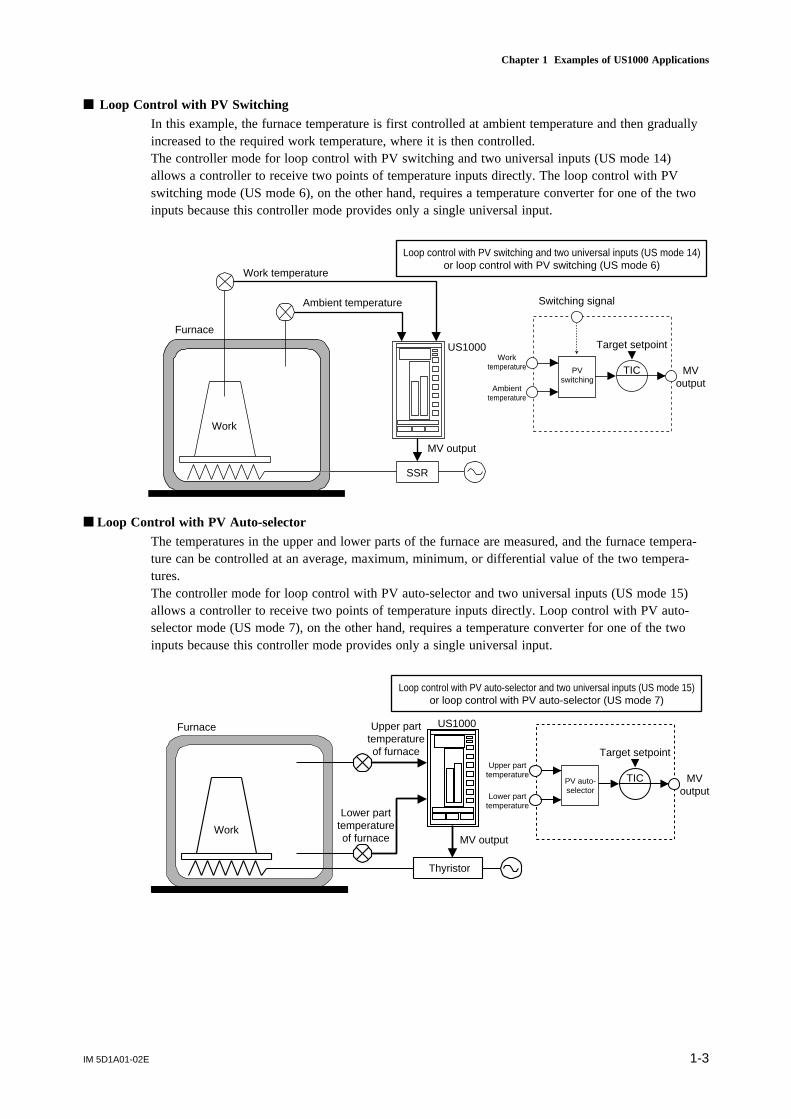
Loop Control with PV SwitchingIn this example, the furnace temperature is first controlled at ambient temperature and then graduallyincreased to the required work temperature, where it is then controlled.The controller mode for loop control with PV switching and two universal inputs (US mode 14)allows a controller to receive two points of temperature inputs directly. The loop control with PVswitching mode (US mode 6), on the other hand, requires a temperature converter for one of the twoinputs because this controller mode provides only a single universal input.
Furnace
Work temperature
Ambient temperature
Work
US1000
MV output
SSR
Loop control with PV switching and two universal inputs (US mode 14)or loop control with PV switching (US mode 6)
TIC
Target setpointWork
temperature MVoutputAmbient
temperature
Switching signal
PVswitching
Loop Control with PV Auto-selectorThe temperatures in the upper and lower parts of the furnace are measured, and the furnace tempera-ture can be controlled at an average, maximum, minimum, or differential value of the two tempera-tures.The controller mode for loop control with PV auto-selector and two universal inputs (US mode 15)allows a controller to receive two points of temperature inputs directly. Loop control with PV auto-selector mode (US mode 7), on the other hand, requires a temperature converter for one of the twoinputs because this controller mode provides only a single universal input.
Furnace
Work
Upper parttemperatureof furnace
Lower parttemperatureof furnace
US1000
MV output
Thyristor
TIC
Target setpointUpper part
temperature MVoutputLower part
temperature
Loop control with PV auto-selector and two universal inputs (US mode 15)or loop control with PV auto-selector (US mode 7)
PV auto-selector

IM 5D1A01-02E1-4
Loop Control with PV-hold FunctionDuring replacing the works in the furnace, PV and MV values can be held by the contact input.So that, PV low limit alarm or MV wind-up won't occur when the temperature in the furnace de-creases temporarily according to replacing the works.
Furnace
Work
Switchingsignal
PVUS1000
MV output
SSR
Loop control with PV-hold function (US mode 8)
TIC
Target setpoint
PV MVoutput
Switching signal
Manualoperation
PVholding
Temperature and Humidity ControlDry- and wet-bulb temperatures can be controlled using a single US1000 controller for an air condi-tioning system. (US1000-11 only)
US1000
Wet-bulb temperature
Dry-bulb temperature
Start/Stop
Thyristor
HeaterAir
conditioningsystem
SprayLoad
Pump
Temperature and humidity control (US mode 12)
TIC
Target setpoint
Wet-bulbtemperature
MVoutput
forheater
Dry-bulbtemperature
TIC
Target setpoint
MVoutput
forspray
Relativehumiditycalculation
MV outputfor heater
MV outputfor spray
IM 5D1A01-02E 2-1
Chapter 2 Controller Mode (US Mode)
2. Controller Mode (US Mode)
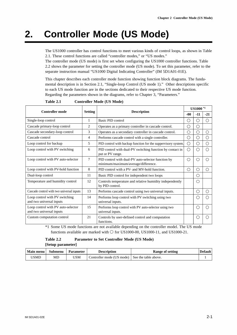
The US1000 controller has control functions to meet various kinds of control loops, as shown in Table2.1. These control functions are called “controller modes,” or “US modes.”The controller mode (US mode) is first set when configuring the US1000 controller functions. Table2.2 shows the parameter for setting the controller mode (US mode). To set this parameter, refer to theseparate instruction manual “US1000 Digital Indicating Controller” (IM 5D1A01-01E).
This chapter describes each controller mode function showing function block diagrams. The funda-mental description is in Section 2.1, “Single-loop Control (US mode 1).” Other descriptions specificto each US mode function are in the sections dedicated to their respective US mode function.Regarding the parameters shown in the diagrams, refer to Chapter 3, “Parameters.”
Table 2.1 Controller Mode (US Mode)
DescriptionSettingUS1000 *1
Controller mode
Single-loop control
-00 -11 -21
1
2
3
5
4
6
Basic PID control
Cascade primary-loop control Operates as a primary controller in cascade control.
Cascade secondary-loop control Operates as a secondary controller in cascade control.
Cascade control Performs cascade control with a single controller.
Loop control for backup PID control with backup function for the suppervisory system.
Loop control with PV switching PID control with dual-PV switching function by contact input or PV range.
7Loop control with PV auto-selector PID control with dual-PV auto-selector function by minimum/maximum/average/difference.
8Loop control with PV-hold function PID control with a PV- and MV-hold function.
11Dual-loop control Basic PID control for independent two loops
12Temperature and humidity control Controls temperature and relative humidity independently by PID control.
13Cascade control with two universal inputs Performs cascade control using two universal inputs.
14Loop control with PV switchingand two universal inputs
Performs loop control with PV switching using two universal inputs.
15
21
Loop control with PV auto-selectorand two universal inputs
Performs loop control with PV auto-selector using two universal inputs.
Custom computation control Controls by user-defined control and computation functions.
*1 Some US mode functions are not available depending on the controller model. The US modefunctions available are marked with for US1000-00, US1000-11, and US1000-21.
Table 2.2 Parameter to Set Controller Mode (US Mode)[Setup parameter]
Range of settingDescriptionSubmenu DefaultMain menu
USMD MD
Parameter
USM Controller mode (US mode) See the table above. 1
IM 5D1A01-02E2-2
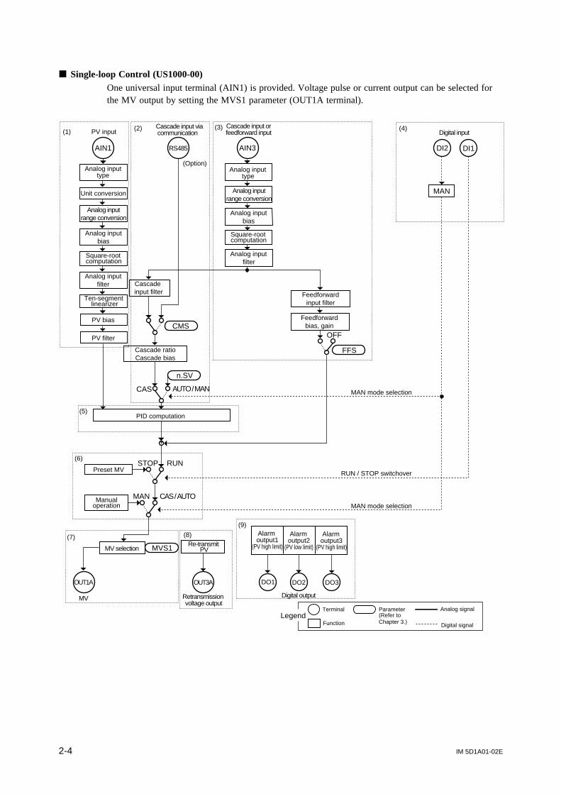
2.1 Single-loop Control (US mode 1)This controller mode provides the basic control functions with a single control computation unit.Following is a description of how to read the function block diagram for single-loop control (US1000-00). The numbers in parentheses correspond to the numbers in the diagram. Most of these descriptionscan also be applied to the function diagrams for other US modes.
(1) PV input sectionA series of computations can be performed on the PV input from the AIN1 terminal. The AIN1terminal is a universal analog input terminal that can receive direct signals from a thermocouple orRTD, or voltage signal. For information about the computations provided on the PV input, refer toSection 3.2, “Parameters for Analog Input,” and Section 3.3, “Parameters for PV Computation.”
(2) Cascade input section (Optional communication function)Cascade input is used in control such as the flow rate ratio control introduced in Chapter 1.The RS-485 terminal is the communication input terminal for the RS-485 and is provided for control-lers with optional communication functions.In CAS operation mode, the US1000 controller performs control using the cascade input from the RS-485 or AIN3 terminal as the target setpoint instead of using the value set with the parameter n.SV.Whether to use RS-485 or AIN3 terminal for cascade input can be specified using the parameter CMS.For information about the CMS parameter and cascade input, refer to Section 3.4, “Parameters forCascade Input.”
(3) Cascade input section (AIN3 terminal)The AIN3 terminal is an analog input terminal for voltage input. Like the RS485 terminal mentionedabove, the input from the AIN3 terminal can be used as a cascade input, and computations can beperformed on the input. For information about the computations on inputs, refer to Section 3.2,“Parameters for Analog Input.”The input from AIN3 terminal can also be used as a feedforward input by setting the parameter FFS toAIN. In this case, the parameter CMS must be set to CPT. The feedforward input value will be addedto the result of PID computation. For information about feedforward input, refer to Section 3.5,“Parameters for Feedforward Input.”
(4) Contact input sectionTwo contact input terminals DI1 and DI2 are provided. At the time of shipping, the functions forswitching between RUN/STOP and to switch the operation mode to MAN are assigned to DI1 andDI2 terminals, respectively. For detailed information about the functions assigned to contact inputs,refer to Table 2.3.The assigned function can be changed to other functions (e.g., switching to AUTO mode). Refer toSection 3.15, “Parameters for Contact Input,” for how to change.
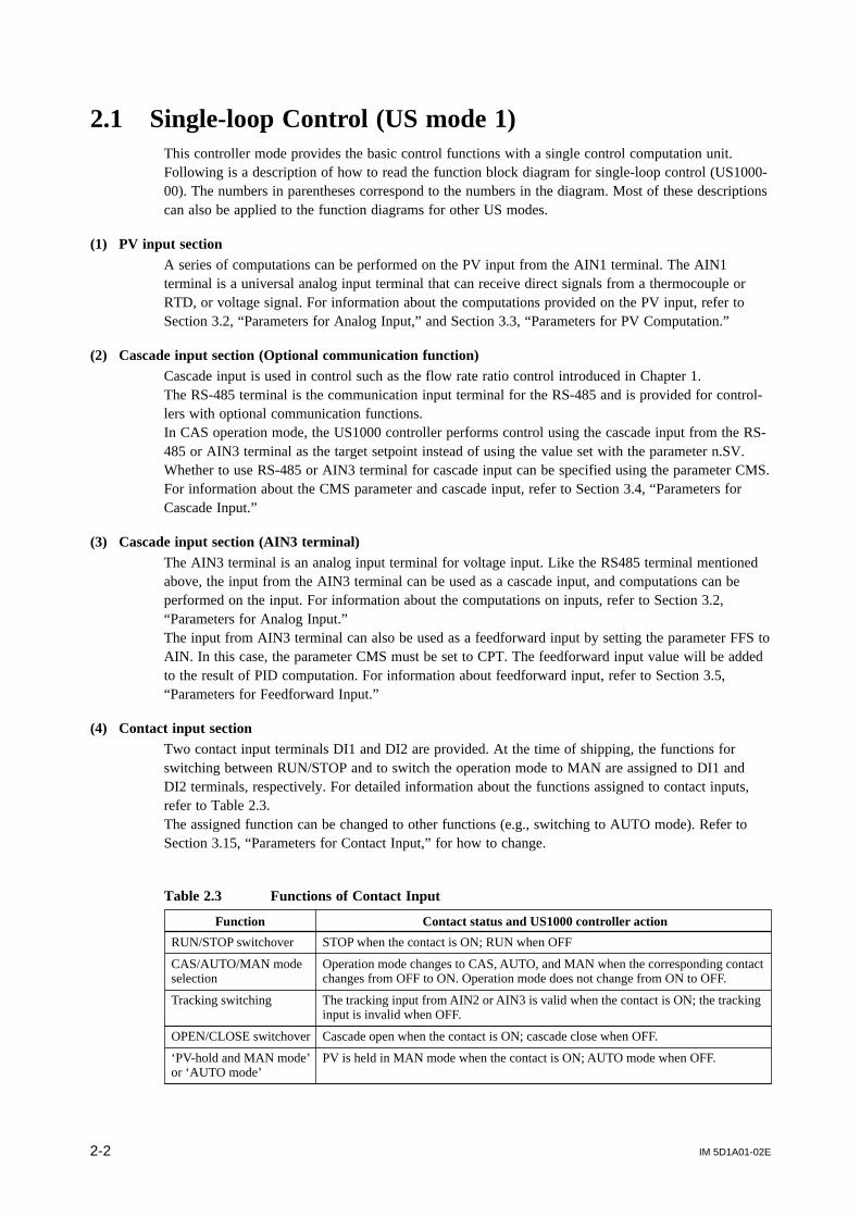
Table 2.3 Functions of Contact Input
Contact status and US1000 controller actionFunction
RUN/STOP switchover STOP when the contact is ON; RUN when OFF
CAS/AUTO/MAN modeselection
Operation mode changes to CAS, AUTO, and MAN when the corresponding contactchanges from OFF to ON. Operation mode does not change from ON to OFF.
Tracking switching The tracking input from AIN2 or AIN3 is valid when the contact is ON; the trackinginput is invalid when OFF.
‘PV-hold and MAN mode’or ‘AUTO mode’
PV is held in MAN mode when the contact is ON; AUTO mode when OFF.
OPEN/CLOSE switchover Cascade open when the contact is ON; cascade close when OFF.

IM 5D1A01-02E 2-3
Chapter 2 Controller Mode (US Mode)
(5) PID computation unitThe PID computation unit, which represents the core of the control. For information about the PIDcomputation unit, refer to Section 3.9, “Parameters for PID Computation.”
(6) RUN/STOP and operation mode switching sectionThe controller operates when the signal from DI1 terminal is off, and stops when the signal is on.When the controller is stopped, the preset MV value is set with the parameter n.PM or n.PMc outputas MV output. For information about the parameter n.PM and n.PMc, refer to subsection 3.12.4,“Preset MV.”Operation mode can be switched to CAS, AUTO, and MAN using the , , and keys onthe controller’s front panel, respectively.In MAN mode, the MV output can be operated using the , , and keys on thecontroller’s front panel. For information about the operation mode and operations, refer to Chapter 6,“Operation,” in the separate instruction manual “US1000 Digital Indicating Controller” (IM 5D1A01-01E).
(7) MV output sectionThe result of control computation is output to the OUT1A terminal as an MV output. The type of MVoutput can be selected from voltage pulse and current using the MVS1 parameter. For informationabout MV outputs, refer to Section 3.8, “Parameters for Control Computation,” and Section 3.12,“Parameters for MV.”
(8) Retransmission output sectionThe OUT3A terminal is used solely for retransmission output. Retransmission output is the functionfor retransmitting the signal of PV, SV, or MV data in the controller to a device such as a recorder. Atthe time of shipping, the function is set to retransmit PV. For information about the retransmissionoutput, refer to Section 3.13, “Parameters for Retransmission Output.”
(9) Contact output sectionThree contact output terminals DO1, DO2, and DO3 are provided. At the time of shipping, the PVhigh limit, PV low limit, and PV high limit (to be used as the high-high limit) alarms are assigned tothe respective terminals. For information about alarm functions, refer to Section 3.14, “Parameters forAlarm Output.”
IM 5D1A01-02E2-4
Single-loop Control (US1000-00)One universal input terminal (AIN1) is provided. Voltage pulse or current output can be selected forthe MV output by setting the MVS1 parameter (OUT1A terminal).
PV inputCascade input via communication
DI2 DI1AIN1 AIN3
PID computation
+
Re-transmit PVMVS1
STOP RUN
MAN CAS / AUTO
OUT3AOUT1A
FFS
MV Retransmission voltage output
OFF
Cascade input filter
Cascade ratioCascade bias
CMS
n.SV
AUTO / MAN
RS485
MAN mode selection
DO1 DO2 DO3
CAS
RUN / STOP switchover
Cascade input orfeedforward input Digital input
Digital output
MAN mode selection
Analog input range conversion
Analog input bias
Square-root computation
Analog input filter
Ten-segment linearizer
Unit conversion
Analog input type
PV bias
PV filter
Preset MV
Manualoperation
Analog input range conversion
Analog input bias
Analog input filter
Analog input type
Square-root computation
Feedforward input filter
MAN
Feedforward bias, gain
MV selection
Alarm output1
(PV high limit)
Alarm output2
(PV low limit)
Alarm output3
(PV high limit)
LegendTerminal
Function
Parameter(Refer toChapter 3.)
Analog signal
Digital signal
(Option)
(1) (2) (3) (4)
(5)
(6)
(7) (8)
(9)

IM 5D1A01-02E 2-5
Chapter 2 Controller Mode (US Mode)
Single-loop Control (US1000-11)One universal input terminal (AIN1) is provided. The type of MV output can be selected from those inthe table below by setting the MVS1 parameter.
Table 2.4 MV Output for US1000-11
Type of control computation (Value of MVS1 *1)
Heating/coolingcomputation (7 to 9)
Heating/coolingcomputation (4 to 6)
TerminalNo. Heating/cooling
computation (10 to 12)
Terminalcode
OUT1A 16, 18
Time proportional PID (0, 1)Continuous PID (2)
ON/OFF computation (3)
Retransmission output (4)Heating pulse output (5)Heating current output (6)
Retransmission output (7)Heating pulse output (8)Heating current output (9)
Retransmission output (10)Heating pulse output (11)Heating current output (12)
Retransmission output (0, 3)Voltage pulse output (1)Current output (2)
OUT2A 49, 50 Retransmission output 2 Cooling pulse output Cooling current outputRetransmission output 2
OUT1R 55 to 57Heating control relay output (4)Alarm output 4 (5, 6)
Heating control relay output (7)Alarm output 4 (8, 9)
Heating control relay output (10)Alarm output 4 (11, 12)
Control relay output (0, 3)Alarm output 4 (1, 2)
OUT2R 58 to 60 Cooling control relay output Alarm output 3 Alarm output 3Alarm output 3
*1 Value of MVS2 for cascade control and cascade control with two universal inputs.

IM 5D1A01-02E2-6
DO3 DO4DO2 DO6 DO7DO5DO1
Re-transmitPV
OUT3A
Retransmission voltage output 3
OUT1A OUT1R OUT2A OUT2R
Analog input range conversion
Analog input bias
Square-root computation
Analog input filter
Ten-segment linearizer
PV inputCascade input orfeedforward input
Cascade input via communication
MV selection
MV
MVS1
Unit conversion
MAN
Cascade ratioCascade bias
PID computation
AIN3AIN1
PV bias
PV filter
STOP
Cascade input filter
AUTO / MANn.SV
Analog input range conversion
Analog input bias
Analog input filter
DI3 DI2 DI1DI7 DI6 DI5 DI4
CMS
Feedforward input filter
Feedforward bias, gain
FFS
OFF
CAS / AUTO
RUN
SV number selection
RUN / STOP switching
AUTO mode selection or MAN mode selection
AUTO mode selection or MAN mode selection
RS485
Analog input type
Analog input type
CAS
(Option)
Square-root computation
Preset MV
Manualoperation
DO will beOFF whenFAIL output
LegendTerminal
Function
Parameter Analog signal
Digital signal
Digital output
Alarm output1
(PV high limit)
Alarm output2
(PV low limit)
Alarm output3
(PV high limit)
Alarm output4
(PV low limit)
Digital input
MANAUTO

IM 5D1A01-02E 2-7
Chapter 2 Controller Mode (US Mode)
Single-loop Control (US1000-21)Control is performed based on a position-proportional PID computation so as to ensure that the MVoutput and control valve opening always match. One universal input terminal (AIN1) is provided. TheMV output is a position-proportional control relay output (OUTR terminal). A valve position feedbackinput is provided.
PV inputCascade input orfeedforward input
PV bias
PV filter
Cascade input filter
DI3 DI2 DI1AIN3 DI7 DI6 DI5 DI4
DO3 DO4DO2 DO6 DO7DO5DO1
AIN1
Cascade ratioCascade bias
CMS
PID computation
+
STOP RUN
MAN CAS / AUTO
OUT3AOUTR
FFS
n.SV
Feedforward bias, gain
Feedforward input filter
SV number selection
AUTO mode selection or MAN mode selection
RUN / STOP switching
Positionproportionalcontrol relay
output
AUTO / MAN
OFF
CAS
RS485
DO will beOFF whenFAIL output
OUT1AFBIN
AUTO mode selection or MAN mode selection
Retransmission current output
Valve position feedback input
LegendTerminal
Function
Parameter Analog signal
Digital signal
Analog input range conversion
Analog input bias
Square-root computation
Analog input filter
Ten-segment linearizer
Unit conversion
Analog input type
Cascade input via communication
(Option)
Analog input range conversion
Analog input bias
Square-root computation
Analog input filter
Analog input type
Re-transmit MV
Re-transmit PV
Retransmission voltage output
Digital input
Digital output
Preset MV
Manualoperation
AUTO MAN
Alarm output1
(PV high limit)
Alarm output2
(PV low limit)
Alarm output3
(PV high limit)
Alarm output4
(PV low limit)

IM 5D1A01-02E2-8
2.2 Cascade Primary-loop Control (US mode 2)This US mode sets up a controller as the primary loop controller when cascade control is to beperformed using two controllers.The mode provides an output tracking function and an error signal output to the secondary loopcontroller, both of which are required for a cascade primary loop.
Cascade Primary-loop Control (US1000-00)One universal input terminal (AIN1) is provided. The MV output is a current output (OUT1A termi-nal). Leave the MVS1 parameter setting at the default value (2).
DI2 DI1AIN1 AIN3
STOP RUN
MAN CAS / AUTO
OUT3A
n.SV
AUTO/MAN
RS485
DO1 DO2 DO3
CAS
Tracking switching
OUT1A
Secondary loop controller
Tracking signal
Retransmission voltage output 3
MV
RUN / STOP switching
PID computation
Cascade ratioCascade bias
Analog input type
Analog input range conversion
Analog input bias
Square-root computation
Analog input filter
Ten-segment linearizer
Unit conversion
PV bias
PV filter
(Option)
Cascade input via communication
Analog input type
Analog input range conversion
Analog input bias
Analog input filter
Square-root computation
PV input
Preset MV
Manualoperation
Re-transmitPV
LegendTerminal
Function
Parameter Analog signal
Digital signal
Digital output
Alarm output1
(PV high limit)
Alarm output2
(PV low limit)
DO will be OFFwhen input burnoutor AD error occurs
Digital input
250 Ω
IM 5D1A01-02E 2-9
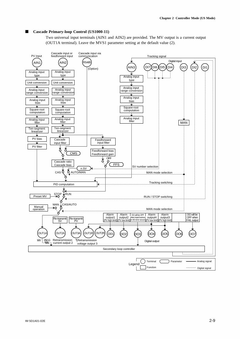
Chapter 2 Controller Mode (US Mode)
Cascade Primary-loop Control (US1000-11)Two universal input terminals (AIN1 and AIN2) are provided. The MV output is a current output(OUT1A terminal). Leave the MVS1 parameter setting at the default value (2).
DO3 DO4DO2 DO6 DO7DO5D01
DI3 DI2 DI1
AIN1 AIN2
AIN3Analog input
type
Unit conversion
Analog input range conversion
Square-root computation
Analog input filter
Ten-segment linearizer
PV bias
PV filter
Analog input bias
Cascade input filter
Analog input range conversion
Cascade ratioCascade bias
Feedforward biasFeedforward gainCMS
FFSn.SV
PID computation
Feedforward input filter
Analog input bias
Square-root computation
SV number selection
MAN mode selection
Tracking switching
MAN mode selection
RUN / STOP switching
MAN
STOP
CAS
RUN
CAS/AUTO
OUT1A OUT2A OUT3A OUT1R OUT2R
Secondary loop controller
MV Retransmission voltage output 3
RS485
PV inputCascade input orfeedforward input
Cascade input via communication Tracking signal
OFF
(Option)
AUTO/MAN
Analog input type Analog input
typeUnit conversion
Analog input range conversion
Analog input bias
Square-root computation
Analog input filter
Ten-segment linearizer
Analog input filter
Retransmission current output 2
Preset MV
Manualoperation
Re-transmitSV
Re-transmitPV
DO will beOFF whenFAIL output
LegendTerminal
Function
Parameter Analog signal
Digital signal
Digital output
Alarm output1
(PV high limit)
Alarm output2
(PV low limit)
Alarm output3
(PV high limit)
Alarm output4
(PV low limit)
DO will be OFFwhen input burnoutor AD error occurs
250 Ω
DI7 DI6 DI5 DI4
Digital input
MAN

IM 5D1A01-02E2-10
2.3 Cascade Secondary-loop Control (US mode 3)This US mode sets up a controller as the secondary loop controller when cascade control is to beperformed using two controllers.The mode provides a setpoint output function and a signal tracking output to the primary loop control-ler, both of which are required for a cascade secondary loop.
Cascade Secondary-loop Control (US1000-00)One universal input terminal (AIN1) is provided. Voltage pulse or current output can be selected forthe MV output by setting the MVS1 parameter (OUT1A terminal).
DI2 DI1AIN1 AIN3
STOP RUN
MAN CAS / AUTO
OUT3A
MV
CMS
AUTO / MAN
RS485
DO1 DO2 DO3
CAS
OUT1A
Primary loop controller
250 Ω
MV selection
n.SV
MVS1
Retransmission voltage output 3
PID computation
Cascade ratioCascade bias
Cascade input filter
Analog input type
Analog input range conversion
Analog input bias
Square-root computation
Analog input filter
Ten-segment linearizer
Unit conversion
PV bias
PV filter
Analog input type
Analog input range conversion
Analog input bias
Analog input filter
Square-root computation
PV inputCascade input via communication
(Option)
Error signal
Tracking switching
Tracking signal
RUN / STOP switching
Switch to AUTO mode from CAS mode when DI2 is OFF
Preset MV
Manualoperation
Re-transmitSV
DO will be OFFwhen CAS mode
is selected
LegendTerminal
Function
Parameter Analog signal
Digital signal
Digital output
Alarm output1
(PV high limit)
Alarm output2
(PV low limit)
Digital input

IM 5D1A01-02E 2-11
Chapter 2 Controller Mode (US Mode)
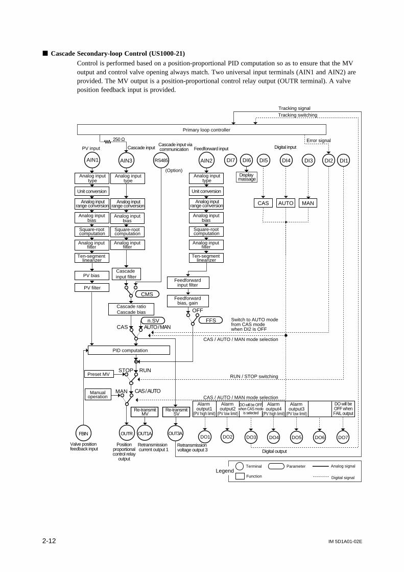
Cascade Secondary-loop Control (US1000-11)Two universal input terminals (AIN1 and AIN2) are provided. The type of MV output can be selectedfrom those in Table 2.4 in Section 2.1 by setting the MVS1 parameter.
Cascade input
DI3 DI2 DI1DI7 DI6 DI5 DI4
DO7
AIN1 AIN3
+
MVS1
STOP RUN
MAN CAS / AUTO
OUT3AOUT1A OUT1R OUT2A OUT2R
FFS
OFF
Primary loop controller
250 Ω
Tracking signal
Tracking switching
AIN2
CMS
n.SVAUTO / MAN
RS485
Error signal
CAS / AUTO / MAN mode selection
DO1 DO2 DO3 DO4 DO5 DO6
Feedforward input
CAS
Retransmission voltage output 3
MV
MV selection
RUN / STOP switching
CAS / AUTO / MAN mode selection
PID computation
Cascade ratioCascade bias
Cascade input filter
Feedforward input filter
Feedforward bias, gain
Analog input type
Analog input range conversion
Analog input bias
Square-root computation
Analog input filter
Ten-segment linearizer
Unit conversion
PV bias
PV filter
Analog input type
Analog input range conversion
Analog input bias
Analog input filter
Square-root computation
PV inputCascade input via communication
(Option)Display massage
Analog input type
Analog input range conversion
Analog input bias
Square-root computation
Analog input filter
Ten-segment linearizer
Unit conversion
Preset MV
Manualoperation
Re-transmitSV
DO will beOFF whenFAIL output
DO will be OFFwhen CAS mode
is selected
LegendTerminal
Function
Parameter Analog signal
Digital signal
Digital output
Alarm output1
(PV high limit)
Alarm output2
(PV low limit)
Alarm output4
(PV high limit)
Alarm output3
(PV low limit)
Switch to AUTO mode from CAS mode when DI2 is OFF
Digital input
MANCAS AUTO
IM 5D1A01-02E2-12
Cascade Secondary-loop Control (US1000-21)Control is performed based on a position-proportional PID computation so as to ensure that the MVoutput and control valve opening always match. Two universal input terminals (AIN1 and AIN2) areprovided. The MV output is a position-proportional control relay output (OUTR terminal). A valveposition feedback input is provided.
DI3 DI2 DI1AIN3 DI7 DI6 DI5 DI4AIN1
CMS
+
STOP RUN
MAN CAS / AUTO
OUT3AOUTR
FFSn.SVAUTO / MAN
OFF
CAS
RS485
OUT1AFBIN
Primary loop controller
250 Ω
Tracking signalTracking switching
Feedforward input
Error signal
AIN2
CAS / AUTO / MAN mode selection
RUN / STOP switching
CAS / AUTO / MAN mode selection
Retransmission voltage output 3
Valve position feedback input
Retransmission current output 1
PID computation
Cascade ratioCascade bias
Cascade input filter
Feedforward input filter
Feedforward bias, gain
PV input
Analog input type
Analog input range conversion
Analog input bias
Square-root computation
Analog input filter
Ten-segment linearizer
Unit conversion
PV bias
PV filter
Analog input type
Analog input range conversion
Analog input bias
Analog input filter
Square-root computation
Cascade inputCascade input via communication
(Option) Analog input
type
Analog input range conversion
Analog input bias
Square-root computation
Analog input filter
Ten-segment linearizer
Unit conversion
Preset MV
Manualoperation
DO7DO1 DO2 DO3 DO4 DO5 DO6
Re-transmitSV
Re-transmitMV
DO will beOFF whenFAIL output
DO will be OFFwhen CAS mode
is selected
LegendTerminal
Function
Parameter Analog signal
Digital signal
Digital output
Alarm output1
(PV high limit)
Alarm output2
(PV low limit)
Alarm output4
(PV high limit)
Alarm output3
(PV low limit)
Display massage
MANCAS AUTO
Digital input
Switch to AUTO modefrom CAS mode when DI2 is OFF
Positionproportionalcontrol relay
output
IM 5D1A01-02E 2-13
Chapter 2 Controller Mode (US Mode)
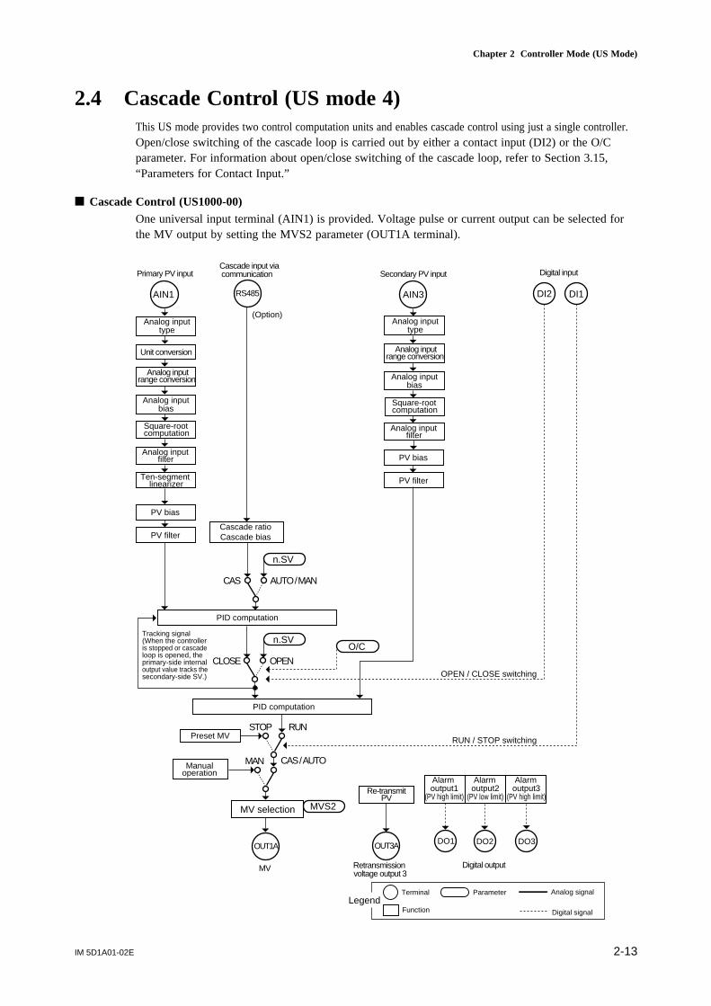
2.4 Cascade Control (US mode 4)This US mode provides two control computation units and enables cascade control using just a single controller.Open/close switching of the cascade loop is carried out by either a contact input (DI2) or the O/Cparameter. For information about open/close switching of the cascade loop, refer to Section 3.15,“Parameters for Contact Input.”
Cascade Control (US1000-00)One universal input terminal (AIN1) is provided. Voltage pulse or current output can be selected forthe MV output by setting the MVS2 parameter (OUT1A terminal).
OUT3AOUT1A
MV selection MVS2
MAN
AIN1
STOP
AUTO / MAN
n.SV
DI2 DI1
CAS / AUTO
RUN
CAS
RS485 AIN3
n.SV
OPENCLOSE
O/C
Secondary PV input
RUN / STOP switching
OPEN / CLOSE switching
Retransmission voltage output 3
PID computation
PID computation
Cascade ratioCascade bias
Analog input range conversion
Analog input bias
Square-root computation
Analog input filter
Ten-segment linearizer
Unit conversion
PV bias
PV filter
Analog input type
Primary PV input
(Option)
Cascade input via communication
PV bias
PV filter
Analog input type
Analog input range conversion
Analog input bias
Analog input filter
Square-root computation
Preset MV
Manualoperation
DO3DO2DO1
MV
Re-transmitPV
LegendTerminal
Function
Parameter Analog signal
Digital signal
Digital output
Alarm output1
(PV high limit)
Alarm output2
(PV low limit)
Alarm output3
(PV high limit)
Digital input
Tracking signal(When the controlleris stopped or cascadeloop is opened, theprimary-side internaloutput value tracks thesecondary-side SV.)

IM 5D1A01-02E2-14
Cascade Control (US1000-11)Two universal input terminals (AIN1 and AIN2) are provided. The type of MV output can be selectedfrom those in Table 2.4 in Section 2.1 by setting the MVS2 parameter.
DI3 DI2 DI1DI7 DI6 DI5 DI4AIN1 AIN2
+
MVS2
STOP RUN
MAN CAS / AUTO
OUT3AOUT1A OUT1R OUT2A OUT2R
FFS
OFF
CMS
n.SV
AUTO / MAN
RS485
CAS
O/CCLOSE OPEN
n.SV
CAS / AUTO / MAN mode selection
RUN / STOP switching
OPEN / CLOSE switching
Retransmission voltage output 3
MV
MV selection
PID computation
PID computation
Cascade ratioCascade bias
Cascade input filter
Analog input range conversion
Analog input bias
Square-root computation
Analog input filter
Ten-segment linearizer
Unit conversion
PV bias
PV filter
Analog input type
Primary PV input
(Option)
Cascade input via communication
Cascade input orfeedforward input
CAS / AUTO / MAN mode selection
AIN3
Secondary PV input
Analog input range conversion
Analog input bias
Square-root computation
Analog input filter
Analog input type
PV bias
PV filter
Feedforward input filter
Feedforward bias, gain
Analog input range conversion
Analog input bias
Square-root computation
Analog input filter
Ten-segment linearizer
Unit conversion
Analog input type
Preset MV
Manualoperation
DO3 DO4DO2 DO6 DO7DO5DO1
Re-transmitPV
DO will beOFF whenFAIL output
LegendTerminal
Function
Parameter Analog signal
Digital signal
Digital output
Alarm output1
(PV high limit)
Alarm output2
(PV low limit)
Alarm output3
(PV high limit)
Alarm output4
(PV low limit)
Display massage
MANCAS AUTO
Digital input
Tracking signal(When the controlleris stopped or cascadeloop is opened, theprimary-side internaloutput value tracks thesecondary-side SV.)

IM 5D1A01-02E 2-15
Chapter 2 Controller Mode (US Mode)
Cascade Control (US1000-21)Control is performed based on a position-proportional PID computation so as to ensure that the MVoutput and control valve opening always match. Two universal input terminals (AIN1 and AIN2) areprovided. The MV output is a position-proportional control relay output (OUTR terminal). A valveposition feedback input is provided.
OUT3AOUTR
MAN
AIN3AIN1
STOP
AUTO / MANn.SV
DI3 DI2 DI1DI7 DI6 DI5 DI4
CMS
FFS
OFF
CAS / AUTO
RUN
CAS
RS485 AIN2
n.SV
OPENCLOSE
O/C
OUT1AFBIN
CAS / AUTO / MAN mode selection
RUN / STOP switching
OPEN / CLOSE switching
Retransmission voltage output 3
Retransmission current output 1
Valve position feedback input
PID computation
PID computation
Cascade ratioCascade bias
Cascade input filter
Analog input range conversion
Analog input bias
Square-root computation
Analog input filter
Ten-segment linearizer
Unit conversion
PV bias
PV filter
Analog input type
Cascade input via communication
(Option)
Cascade input orfeedforward input
PV bias
PV filter Feedforward input filter
Feedforward bias, gain
Analog input range conversion
Analog input bias
Square-root computation
Analog input filter
Analog input type
Analog input range conversion
Analog input bias
Square-root computation
Analog input filter
Ten-segment linearizer
Unit conversion
Analog input type
CAS / AUTO / MAN mode selection
Primary PV input Secondary PV input
Preset MV
Manualoperation
DO3 DO4DO2 DO6 DO7DO5DO1
Re-transmitPV
Re-transmitMV
DO will beOFF whenFAIL output
LegendTerminal
Function
Parameter Analog signal
Digital signal
Digital output
Alarm output1
(PV high limit)
Alarm output2
(PV low limit)
Alarm output3
(PV high limit)
Alarm output4
(PV low limit)
Display massage
Digital input
MANCAS AUTO
Positionproportionalcontrol relay
output
Tracking signal(When the controlleris stopped or cascadeloop is opened, theprimary-side internaloutput value tracks thesecondary-side SV.)

IM 5D1A01-02E2-16
2.5 Loop Control for Backup (US mode 5)This US mode provides a control function that is used in combination with higher-level controlequipment (such as another controller or a programmable controller). Normally, the controller outputsthe MV output received from the higher-level equipment (tracking the input from an AIN3 terminal).On receiving a FAIL signal from the higher-level equipment, the controller starts controlling theequipment instead.
Loop Control for Backup (US1000-00)One universal input terminal (AIN1) is provided. Voltage pulse or current output can be selected forthe MV output by setting the MVS1 parameter (OUT1A terminal).
DO3DO2DO1OUT3AOUT1A
MV selection MVS1
MAN
PID computation
AIN3AIN1
STOP
AUTO / MANn.SV
DI2 DI1
CAS / AUTO
RUN
RS485
CAS
Retransmission voltage output 3
Cascade ratioCascade bias
PV bias
PV filter
Analog input range conversion
Analog input bias
Square-root computation
Analog input filter
Ten-segment linearizer
Unit conversion
Analog input type
Analog input range conversion
Analog input bias
Square-root computation
Analog input filter
Analog input type
PV inputCascade input via communication
(Option)
Tracking input(Backup input)
Tracking switching
RUN / STOP switchingPreset MV
Manualoperation
MV
Re-transmitPV
LegendTerminal
Function
Parameter Analog signal
Digital signal
Digital output
Alarm output1
(PV high limit)
Alarm output2
(PV low limit)
DO will be OFFwhen input burnoutor AD error occurs
Digital input

IM 5D1A01-02E 2-17
Chapter 2 Controller Mode (US Mode)
Loop Control for Backup (US1000-11)Two universal input terminals (AIN1 and AIN2) are provided. The type of MV output can be selectedfrom those in Table 2.4 in Section 2.1 by setting the MVS1 parameter.
DI3 DI2 DI1
DO7
AIN1 AIN3
+
MVS1
STOP RUN
MAN CAS / AUTO
OUT3AOUT1A OUT1R OUT2A OUT2R
FFS
OFF
AIN2
CMS
n.SV
AUTO / MAN
RS485
MAN mode selection
MAN mode selection
DO1 DO2 DO3 DO4 DO5 DO6
CAS
Tracking switching
Tracking input(Backup input)
Retransmission voltage output 3
MV selection
PID computation
Cascade ratioCascade bias
Cascade input filter
PV bias
PV filter
Feedforward input filter
Feedforward bias, gain
PV inputCascade input orfeedforward input
Cascade input via communication
(Option)
Analog input range conversion
Analog input bias
Square-root computation
Analog input filter
Ten-segment linearizer
Unit conversion
Analog input type
Analog input range conversion
Analog input bias
Square-root computation
Analog input filter
Ten-segment linearizer
Unit conversion
Analog input type
Analog input range conversion
Analog input bias
Square-root computation
Analog input filter
Analog input type
SV number selection
RUN / STOP switchingPreset MV
Manualoperation
MV
Re-transmitPV
DO will beOFF whenFAIL output
LegendTerminal
Function
Parameter Analog signal
Digital signal
Digital output
Alarm output1
(PV high limit)
Alarm output2
(PV low limit)
Alarm output3
(PV high limit)
Alarm output4
(PV low limit)
DO will be OFFwhen input burnoutor AD error occurs
DI7 DI6 DI5 DI4
Digital input
MAN

IM 5D1A01-02E2-18
Loop Control for Backup (US1000-21)Control is performed based on a position-proportional PID computation so as to ensure that the MVoutput and control valve opening always match. Two universal input terminals (AIN1 and AIN2) areprovided. The MV output is a position-proportional control relay output (OUTR terminal). A valveposition feedback input is provided.
DI3 DI2 DI1AIN1 AIN3
+
STOP RUN
MAN CAS / AUTO
OUT3AOUTR
FFS
OFF
AIN2
CMS
n.SV
AUTO / MAN
RS485
MAN mode selection
MAN mode selectionCAS
SV number selection
Tracking switching
RUN / STOP switching
OUT1AFBIN
Valve position feedback input
Retransmission current output 1
Retransmission voltage output 3
PID computation
Feedforward input filter
Feedforward bias, gain
Cascade ratioCascade bias
Cascade input filter
PV inputCascade input orfeedforward input
Cascade input via communication
(Option)
Tracking input(Backup input)
Analog input range conversion
Analog input bias
Square-root computation
Analog input filter
Analog input type
PV bias
PV filter
Analog input range conversion
Analog input bias
Square-root computation
Analog input filter
Ten-segment linearizer
Unit conversion
Analog input type
Analog input range conversion
Analog input bias
Square-root computation
Analog input filter
Ten-segment linearizer
Unit conversion
Analog input type
Preset MV
Manualoperation
DO7DO1 DO2 DO3 DO4 DO5 DO6
Re-transmitPV
Re-transmitMV
DO will beOFF whenFAIL output
LegendTerminal
Function
Parameter Analog signal
Digital signal
Digital output
Alarm output1
(PV high limit)
Alarm output2
(PV low limit)
Alarm output3
(PV high limit)
Alarm output4
(PV low limit)
DO will be OFFwhen input burnoutor AD error occurs
Positionproportionalcontrol relay
output
DI7 DI6 DI5 DI4
Digital Input
MAN

IM 5D1A01-02E 2-19
Chapter 2 Controller Mode (US Mode)
2.6 Loop Control with PV Switching (US mode 6)This US mode provides a control function that switches between two PV inputs by a contact inputsignal or according to a PV range. The method of PV switching is specified by USER parameter 3(U3) as shown in the table below, and the range for PV switching is specified by USER parameters 1and 2 (U1, U2).
Table 2.5 USER Parameters for Loop Control with PV Switching
Range of settingDescriptionSubmenu DefaultMain menu
USR –
Parameter
U1 USER parameter 1 PV upper limit for PV switching 0
U2 USER parameter 2 PV lower limit for PV switching 0
U3 USER parameter 3
Switching condition0: Switching within the PV range specified by U1 and U21: Switching at the PV upper limit specified by U12: Switching by contact input
0
The following are the description of the switching methods specified by USER parameter 3.
(1) Switching within the PV range specified by U1 and U2 (U3 = 0)This method should be selected in cases where, for example, two thermocouples are used æ one forhigher temperatures and the other for lower temperatures — and a sudden change in PV must beavoided when switching the thermocouple.In a PV rising process, input switching starts when input 1 reaches the lower limit for PV switching.The PV gradually becomes closer to input 2 and when it exceeds the upper limit for PV switching, thePV completely transfers to input 2. (Figure 2.6.1 (1))Conversely, in a PV falling process, input switching starts when input 2 reaches the upper limit for PVswitching. The PV gradually becomes closer to input 1 and when it falls below the lower limit, the PVcompletely transfers to input 1. (Figure 2.6.1 (2))
PV = Input 1 Switching PV = Input 2
Time
Upper limit forPV switching
Lower limit forPV switching Input 1
(low-temperature side)
Input 2(high-temperature side)
PV
Figure 2.6.1 (1) Switching within Specified PV Range (Rising PV)

IM 5D1A01-02E2-20
PV = Input 2 Switching PV = Input 1
Time
Upper limit forPV switching
Lower limit forPV switching Input 1
(low-temperature side)
Input 2 (high-temperature side)PV
Figure 2.6.1 (2) Switching within Specified PV Range (Falling PV)
(2) Switching at the PV upper limit specified with U1 (U3 = 1)This method should be selected in cases where, for example, two thermocouples are used æ one forhigher temperatures and the other for lower temperatures æ and a sudden change in PV is allowedwhen switching the thermocouple. MV will change smoothly (i.e., without any bumps) however, evenwhen PV changes suddenly.As shown in the figure below, PV = input 1 when input 1 is less than the upper limit for PV switch-ing, and PV = input 2 when input 1 is no less than the upper limit for PV switching. Hysteresis (0.5%of PV range) is provided around the switching point.
PV = Input 1 PV = Input 2
Time
Upper limit forPV switching
Input 1(low-temperature side)
Input 2(high-temperature side) PV
Figure 2.6.2 Switching at the Upper Limit for PV Switching
(3) Switching by contact input (U3 = 2)The PV switching function is assigned to the contact input DI2.
• PV = Input 1 when DI2 = OFF• PV = Input 2 when DI2 = ON
Use of Tracking InputWhen using a tracking input with US1000-11 or US1000-21, a tracking flag function must be assignedto a contact input (DI). For information about contact input assignment, refer to Section 3.15, “Param-eters for Contact Input.”

IM 5D1A01-02E 2-21
Chapter 2 Controller Mode (US Mode)
Loop Control with PV Switching (US1000-00)One universal input terminal (AIN1) is provided. Voltage pulse or current output can be selected forthe MV output by setting the MVS1 parameter (OUT1A terminal).
DO3DO2DO1OUT3A
Retransmissionvoltage output 3
OUT1A
Analog inputrange conversion
Analog inputbias
Square-rootcomputation
Analog inputfilter
Ten-segmentlinearizer
PV input 1Cascade input viacommunication
MV selection
MV
MVS1
Analog inputtype
Unit conversion
MAN
Cascade ratioCascade bias
PID computation
AIN3AIN1
PV bias
PV filter
STOP
AUTO / MANn.SV
DI2 DI1
CAS / AUTO
RUNRUN / STOP switching
RS485
Dual-PVswitching
PV input 2
Analog inputrange conversion
Analog inputbias
Square-rootcomputation
Analog inputfilter
Analog inputtype
U1U2U3
(Option)
CAS
Dual-PV switching
CMS
Preset MV
Manualoperation
Re-transmitPV
LegendTerminal
Function
Parameter Analog signal
Digital signal
Digital output
Alarm output1
(PV high limit)
Alarm output2
(PV low limit)
Alarm output3
(PV high limit)
Digital Input
IM 5D1A01-02E2-22
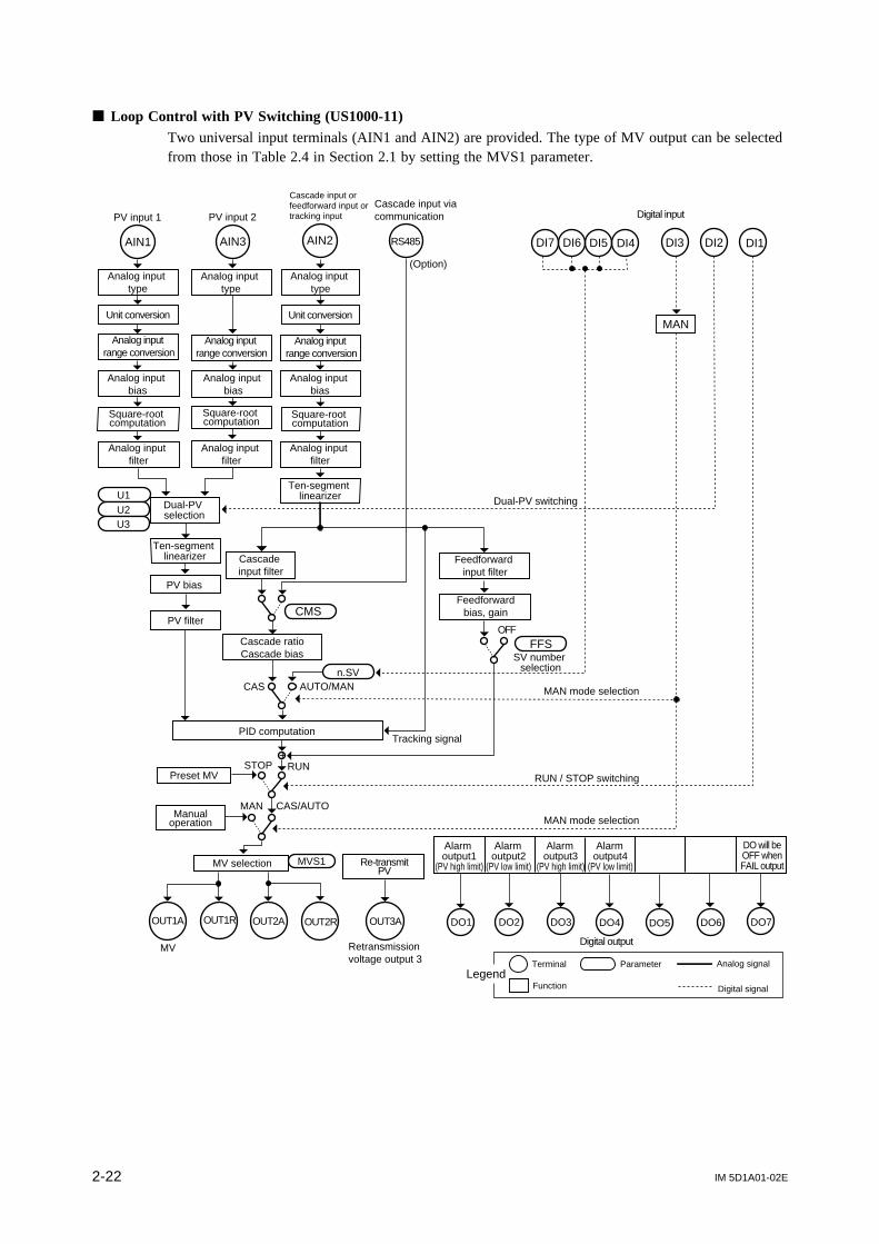
Loop Control with PV Switching (US1000-11)Two universal input terminals (AIN1 and AIN2) are provided. The type of MV output can be selectedfrom those in Table 2.4 in Section 2.1 by setting the MVS1 parameter.
DI3 DI2 DI1AIN1 AIN3 AIN2
Analog input type
Analog input type
Analog input range conversion
Analog input bias
Square-root computation
Analog input filter
PV bias
Cascade input filter
Cascade ratioCascade bias
Feedforwardbias, gainCMS
FFS
n.SV
PID computation
Feedforward input filter
SV number selection
Tracking signal
MAN mode selection
RUN / STOP switching
MAN
STOP
CAS
RUN
CAS/AUTO
OUT1A OUT1R
MV selection
OUT2A OUT2R OUT3A
MV Retransmission voltage output 3
RS485
PV input 1
Cascade input orfeedforward input ortracking input
Cascade input via communication
OFF
Analog input type
Unit conversion
Ten-segment linearizer
MAN mode selection
MVS1
U1Dual-PV selection
PV input 2
U2U3
PV filter
Dual-PV switching
AUTO/MAN
+
(Option)
Square-root computation
Square-root computation
Unit conversion
Analog input range conversion
Analog input range conversion
Analog input bias
Analog input bias
Analog input filter
Analog input filter
Ten-segment linearizer
Preset MV
Manualoperation
DO3 DO4DO2 DO6 DO7DO5DO1
Re-transmitPV
DO will beOFF whenFAIL output
LegendTerminal
Function
Parameter Analog signal
Digital signal
Digital output
Alarm output1
(PV high limit)
Alarm output2
(PV low limit)
Alarm output3
(PV high limit)
Alarm output4
(PV low limit)
DI7 DI6 DI5 DI4
Digital input
MAN

IM 5D1A01-02E 2-23
Chapter 2 Controller Mode (US Mode)
Loop Control with PV Switching (US1000-21)Control is performed based on a position-proportional PID computation so as to ensure that the MVoutput and control valve opening always match. Two universal input terminals (AIN1 and AIN2) areprovided. The MV output is a position-proportional control relay output (OUTR terminal). A valveposition feedback input is provided.
DI3 DI2 DI1AIN1 AIN3 AIN2
Analog inputtype
Analog inputtype
Unit conversion
Analog inputrange conversion
Analog inputbias
Square-rootcomputation
Analog inputfilter
PV bias
Analog inputrange conversion
Analog inputbias
Analog inputfilter
Cascadeinput filter
Cascade ratioCascade bias
Feedforward bias, gainCMS
FFS
n.SV
PID computation
Feedforward inputfilter
SV number selection
Tracking signal
MAN mode selection
RUN / STOP switching
MAN
STOP
CAS
RUN
CAS/AUTO
OUTR OUT3A
Retransmissionvoltage output 3
RS485
PV input 1
Cascade input orfeedforward input ortracking input
Cascade input viacommunication
OFF
Analog inputtype
Unit conversion
Analog inputrange conversion
Analog inputbias
Analog inputfilter
Ten-segmentlinearizer
MAN mode selection
U1Dual-PVselection
PV input 2
Ten-segmentlinearizer
U2U3
PV filter
Dual-PV switching
AUTO/MAN
+
(Option)
OUT1A
Retransmissioncurrent output 1
FBIN
Valve positionfeedback input
Square-rootcomputation
Square-rootcomputation
Preset MV
Manualoperation
DO3 DO4DO2 DO6 DO7DO5DO1
Re-transmitPV
Re-transmitMV
DO will beOFF whenFAIL output
LegendTerminal
Function
Parameter Analog signal
Digital signal
Digital output
Alarm output1
(PV high limit)
Alarm output2
(PV low limit)
Alarm output3
(PV high limit)
Alarm output4
(PV low limit)
DI7 DI6 DI5 DI4
Digital input
MAN
Positionproportionalcontrol relay
output

IM 5D1A01-02E2-24
2.7 Loop Control with PV Auto-selector (US mode 7)This US mode provides a control function that automatically selects either the larger or smaller valueor sets the average value or difference of two PV input values as the PV input. The selection of inputis specified by USER parameter 1 (U1).
Table 2.6 USER Parameters for Loop Control with PV Auto-selector
Range of settingDescriptionSubmenu DefaultMain menu
USR –
Parameter
U1 USER parameter 1
Input selection0: Accepts the maximum value between input 1 and input 21: Accepts the minimum value between input 1 and input 22: Accepts average value of input 1 and input 23: Accepts the difference between input 1 and input 2
(i.e., input 2 - input 1)
2
When using the tracking input with US1000-11 or US1000-21, a tracking flag function must beassigned to a contact input (DI). For information about contact input assignment, refer to Section 3.15,"Parameters for Contact Input."

IM 5D1A01-02E 2-25
Chapter 2 Controller Mode (US Mode)
Loop Control with PV Auto-selector (US1000-00)One universal input terminal (AIN1) is provided. Voltage pulse or current output can be selected forthe MV output by setting the MVS1 parameter (OUT1A terminal).
OUT3A
Retransmissionvoltage output 3
OUT1A
Analog inputrange conversion
Analog inputbias
Square-rootcomputation
Analog inputfilter
Ten-segmentlinearizer
PV input 1Cascade input viacommunication
MV selection MVS1
Analog inputtype
Unit conversion
MAN
Cascade ratioCascade bias
PID computation
AIN3AIN1
PV bias
PV filter
STOP
AUTO / MANn.SV
DI2 DI1
CAS / AUTO
RUNRUN / STOP switching
RS485
Input selection
PV input 2
Analog inputrange conversion
Analog inputtype
U1
(Option)
CAS
AUTO mode selection
MAN mode selection
Analog inputbias
Square-rootcomputation
Analog inputfilter
Preset MV
Manualoperation
DO3DO2DO1
MV
Re-transmitPV
LegendTerminal
Function
Parameter Analog signal
Digital signal
Digital output
Alarm output1
(PV high limit)
Alarm output2
(PV low limit)
Alarm output3
(PV high limit)
Digital input
MAN
IM 5D1A01-02E2-26
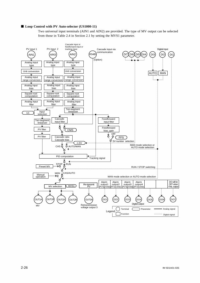
Loop Control with PV Auto-selector (US1000-11)Two universal input terminals (AIN1 and AIN2) are provided. The type of MV output can be selectedfrom those in Table 2.4 in Section 2.1 by setting the MVS1 parameter.
DI3 DI2 DI1AIN1 AIN3 AIN2
Analog input type
Unit conversion
Analog input range conversion
Analog input bias
Square-root computation
Cascade input filter
Cascade ratioCascade bias
Feedforwardbias, gainCMS
FFS
n.SV
PID computation
Feedforward input filter
SV number selection
Tracking signal
MAN mode selection or AUTO mode selection
RUN / STOP switching
MAN
STOP
CAS
RUN
CAS/AUTO
OUT1A OUT1R
MV selection
OUT2A OUT2R OUT3A
MV Retransmission voltage output 3
RS485
PV input 1
Cascade input orfeedforward input ortracking input Cascade input via
communication
OFF
Ten-segment linearizer
MVS1
U1 Input selection
PV input 2
PV filter
AUTO/MAN
(Option)Analog input
typeAnalog input
type
Square-root computation
Square-root computation
Unit conversion
Analog input range conversion
Analog input bias
Analog input bias
Analog input range conversion
Analog input filter
Analog input filter
Analog input filter
Ten-segment linearizer
PV filter
MAN mode selection or AUTO mode selection
Preset MV
Manualoperation
DO3 DO4DO2 DO6 DO7DO5DO1
Re-transmitPV
DO will beOFF whenFAIL output
LegendTerminal
Function
Parameter Analog signal
Digital signal
Digital output
Alarm output1
(PV high limit)
Alarm output2
(PV low limit)
Alarm output3
(PV high limit)
Alarm output4
(PV low limit)
DI7 DI6 DI5 DI4
Digital input
AUTO MAN

IM 5D1A01-02E 2-27
Chapter 2 Controller Mode (US Mode)
Loop Control with PV Auto-selector (US1000-21)Control is performed based on a position-proportional PID computation so as to ensure that the MVoutput and control valve opening always match. Two universal input terminals (AIN1 and AIN2) areprovided. The MV output is a position-proportional control relay output (OUTR terminal). A valveposition feedback input is provided.
OUT3A
Retransmissionvoltage output 3
OUTR
Analog inputrange conversion
Analog inputbias
Square-rootcomputation
Analog inputfilter
Ten-segmentlinearizer
PV input 1Cascade input viacommunication
Analog inputtype
Unit conversion
MAN
Cascade ratioCascade bias
PID computation
AIN3AIN1
PV bias
PV filter
STOP
Cascade inputfilter
AUTO / MANn.SV
DI3 DI2 DI1
CMS
Feedforwardinput filter
Feedforward bias, gain
FFS
OFF
CAS / AUTO
RUN
SV number selection
RUN / STOP switching
RS485
Inputselection
Tracking signal
PV input 2
Analog inputtype
U1
Analog inputtype
Cascade input or feedforward input ortracking input
AIN2
Ten-segmentlinearizer
(Option)
CAS
Unit conversion
MAN mode selection orAUTO mode selection
OUT1A
Retransmissioncurrent output 1
FBIN
Valve positionfeedback input
Analog inputrange conversion
Analog inputrange conversion
Analog inputbias
Analog inputbias
Square-rootcomputation
Square-rootcomputation
Analog inputfilter
Analog inputfilter
MAN mode selection or AUTO mode selection
Preset MV
Manualoperation
DO3 DO4DO2 DO6 DO7DO5DO1
Re-transmitPV
Re-transmitMV
DO will beOFF whenFAIL output
LegendTerminal
Function
Parameter Analog signal
Digital signal
Digital output
Alarm output1
(PV high limit)
Alarm output2
(PV low limit)
Alarm output3
(PV high limit)
Alarm output4
(PV low limit)
DI7 DI6 DI5 DI4
Digital input
AUTO MAN
Positionproportionalcontrol relay
output

IM 5D1A01-02E2-28
2.8 Loop Control with PV-hold Function (US mode 8)This US mode provides a control function that switches the operation mode and holds the PV inputand MV output values upon receiving a contact input signal when the PV input and MV outputbecome erratic due to external disturbance.
When the contact input DI2 is on, the controller holds the PV and MV output values and switches toMAN mode. When the DI2 turns off, the controller continues the operation at the held PV and MVoutput and switches smoothly (i.e., without any bumps) to AUTO mode.
When using the tracking input with US1000-11 or US1000-21, a tracking flag function must beassigned to a contact input (DI). For information about contact input assignment, refer to Section 3.15,“Parameters for Contact Input.”
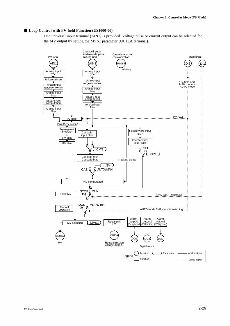
IM 5D1A01-02E 2-29
Chapter 2 Controller Mode (US Mode)
Loop Control with PV-hold Function (US1000-00)One universal input terminal (AIN1) is provided. Voltage pulse or current output can be selected forthe MV output by setting the MVS1 parameter (OUT1A terminal).
PV input
Unit conversion
Analog inputbias
DI2 DI1AIN1 AIN3
PID computation
+STOP RUN
MAN CAS / AUTO
OUT3A
Retransmissionvoltage output 3
Analog inputtype
PV filter
PV bias
Cascade ratioCascade bias
CMS
AUTO / MAN
RS485
Analog inputtype
CAS
RUN / STOP switching
OUT1A
Cascadeinput filter
MV selection
n.SV
Cascade input orfeedforward input ortracking input
PV-hold
Dual-PV selection
Ten-segmentlinearizer
Feedforward bias, gain
Feedforward inputfilter
FFS
MVS1
PV-hold
Tracking signal
OFF
AUTO mode / MAN mode switching
Cascade input viacommunication
(Option)
Analog inputrange conversion
Square-rootcomputation
Analog inputfilter
Analog inputrange conversion
Analog inputbias
Square-rootcomputation
Analog inputfilter
'PV-hold andMAN mode' or'AUTO mode'
Preset MV
Manualoperation
DO3DO2DO1
MV
Re-transmitPV
LegendTerminal
Function
Parameter Analog signal
Digital signal
Digital output
Alarm output1
(PV high limit)
Alarm output2
(PV low limit)
Alarm output3
(PV high limit)
Digital input

IM 5D1A01-02E2-30
Loop Control with PV-hold Function (US1000-11)One universal input terminal (AIN1) is provided. The type of MV output can be selected from those inTable 2.4 in Section 2.1 by setting the MVS1 parameter.
OUT3A
Retransmissionvoltage output 3
OUT1A OUT1R OUT2A OUT2R
PV input
Cascade input orfeedforward input ortracking input
Cascade input viacommunication
MV
MVS1
Unit conversion
MAN
AIN3AIN1
STOP
AUTO / MANn.SV
DI3 DI2 DI1
CMS
FFS
OFF
CAS / AUTO
RUNRUN / STOP switching
AUTO mode / MAN mode switching
PV-hold
CAS mode selection
RS485
(Option)
Analog input type
CAS
Analog input range conversion
Analog inputbias
Square-rootcomputation
Analog inputfilter
Analog input type
Analog input range conversion
Analog inputbias
Square-rootcomputation
Analog inputfilter
PV-hold
Dual-PV selection
Ten-segmentlinearizer
PV filter
PV bias
Cascadeinput filter
Cascade ratioCascade bias
PID computation
MV selection
Feedforward bias, gain
Feedforwardinput filter
'PV-hold andMAN mode' or'AUTO mode'
Preset MV
Manualoperation
DO3 DO4DO2 DO6 DO7DO5DO1
Re-transmitPV
DO will beOFF whenFAIL output
LegendTerminal
Function
Parameter Analog signal
Digital signal
Digital output
Alarm output1
(PV high limit)
Alarm output2
(PV low limit)
Alarm output3
(PV high limit)
Alarm output4
(PV low limit)
SV number selection
Tracking signal
DI7 DI6 DI5 DI4
Digital input
CAS

IM 5D1A01-02E 2-31
Chapter 2 Controller Mode (US Mode)
Loop Control with PV-hold Function (US1000-21)Control is performed based on a position-proportional PID computation so as to ensure that the MVoutput and control valve opening always match. One universal input terminal (AIN1) is provided. TheMV output is a position-proportional control relay output (OUTR terminal). A valve position feedbackinput is provided.
Analog inputfilter
OUT3A
Retransmissionvoltage output 3
PV input
Cascade input orfeedforward input ortracking input
Cascade input viacommunication
MAN
PID computation
AIN3AIN1
STOP
AUTO / MANn.SV
DI3 DI2 DI1
CMS
FFSOFF
CAS / AUTO
RUN
SV number selection
RUN / STOP switching
AUTO mode / MAN mode switching
PV-hold
CAS mode selection
RS485
CAS
OUTR OUT1AFBIN
Valve positionfeedback input
Retransmissioncurrent output 1
Unit conversion
Analog input type
Analog input range conversion
Analog inputbias
Square-rootcomputation
Analog input type
Analog input range conversion
Analog inputbias
Square-rootcomputation
Analog inputfilter
PV-hold
Dual-PV selection
Ten-segmentlinearizer
Cascadeinput filter
Cascade ratioCascade bias
PV filter
PV bias
Feedforward bias, gain
Feedforwardinput filter
'PV-hold andMAN mode' or'AUTO mode'
(Option)
Preset MV
Manualoperation
DO3 DO4DO2 DO6 DO7DO5DO1
Re-transmitPV
Re-transmitMV
DO will beOFF whenFAIL output
LegendTerminal
Function
Parameter Analog signal
Digital signal
Digital output
Alarm output1
(PV high limit)
Alarm output2
(PV low limit)
Alarm output3
(PV high limit)
Alarm output4
(PV low limit)
CAS
Positionproportionalcontrol relay
output
Tracking signal
DI7 DI6 DI5 DI4
Digital input
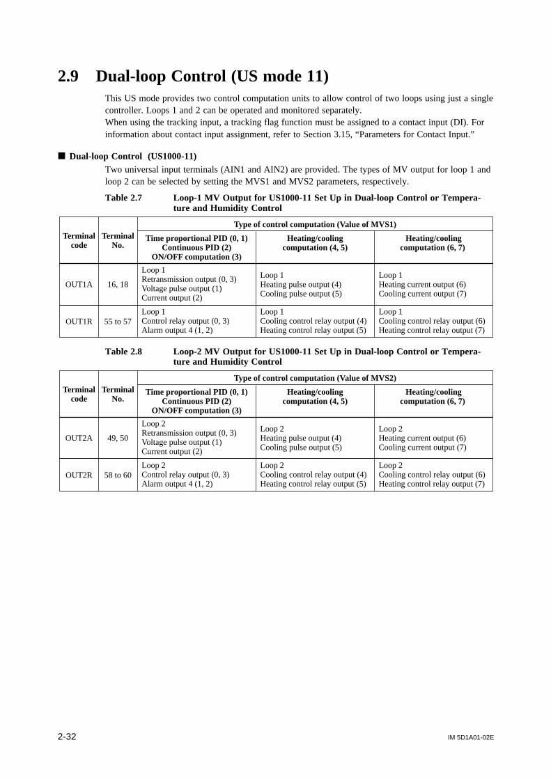
IM 5D1A01-02E2-32
2.9 Dual-loop Control (US mode 11)This US mode provides two control computation units to allow control of two loops using just a singlecontroller. Loops 1 and 2 can be operated and monitored separately.When using the tracking input, a tracking flag function must be assigned to a contact input (DI). Forinformation about contact input assignment, refer to Section 3.15, “Parameters for Contact Input.”
Dual-loop Control (US1000-11)Two universal input terminals (AIN1 and AIN2) are provided. The types of MV output for loop 1 andloop 2 can be selected by setting the MVS1 and MVS2 parameters, respectively.
Table 2.7 Loop-1 MV Output for US1000-11 Set Up in Dual-loop Control or Tempera-ture and Humidity Control
Type of control computation (Value of MVS1)
Heating/coolingcomputation (4, 5)
Time proportional PID (0, 1)Continuous PID (2)
ON/OFF computation (3)
TerminalNo.
Heating/coolingcomputation (6, 7)
Terminalcode
OUT1A 16, 18
Loop 1Retransmission output (0, 3)Voltage pulse output (1)Current output (2)
Loop 1Heating pulse output (4)Cooling pulse output (5)
Loop 1Heating current output (6)Cooling current output (7)
OUT1R 55 to 57Loop 1Control relay output (0, 3)Alarm output 4 (1, 2)
Loop 1Cooling control relay output (4)Heating control relay output (5)
Loop 1Cooling control relay output (6)Heating control relay output (7)
Table 2.8 Loop-2 MV Output for US1000-11 Set Up in Dual-loop Control or Tempera-ture and Humidity Control
Type of control computation (Value of MVS2)
Heating/coolingcomputation (4, 5)
Time proportional PID (0, 1)Continuous PID (2)
ON/OFF computation (3)
TerminalNo.
Heating/coolingcomputation (6, 7)
Terminalcode
OUT2A 49, 50
Loop 2Retransmission output (0, 3)Voltage pulse output (1)Current output (2)
Loop 2Heating pulse output (4)Cooling pulse output (5)
Loop 2Heating current output (6)Cooling current output (7)
OUT2R 58 to 60Loop 2Control relay output (0, 3)Alarm output 4 (1, 2)
Loop 2Cooling control relay output (4)Heating control relay output (5)
Loop 2Cooling control relay output (6)Heating control relay output (7)

IM 5D1A01-02E 2-33
Chapter 2 Controller Mode (US Mode)
AIN1
Analog input type
Unit conversion
Analog input range conversion
Analog inputbias
Square-rootcomputation
Analog inputfilter
Ten-segment linearizer
Cascadeinput filter
Cascade ratioCascade bias
CMS
AUTO1 / MAN1
PID computation 1
MAN1
CAS1
RS485
PV input 1
AIN3
Analog inputtype
Analog inputrange conversion
Analog inputbias
Square-rootcomputation
Analog inputfilter
Cascade input orfeedforward input ortracking input
Cascade inputvia communication
AIN2
Analog inputrange conversion
Analog inputtype
Analog inputbias
Square-rootcomputation
Analog inputfilter
FFS
OFFPV bias
PV filter
STOP RUN
CAS1 / AUTO1
OUT1A OUT1R
MV2MV1
MV selection MVS1
OUT2A OUT2R
MV selection MVS2
OUT3A
Retransmissionvoltage output 3
Alarmoutput 4for loop-1
(PV low limit)
Alarmoutput 4for loop-2
(PV low limit)
PID computation 2
PV bias
PV filter
PV input 2
Cascadeinput filter
Cascade ratioCascade bias
CMS
CAS2n.SV
AUTO2/MAN2n.SV
MAN2
STOP RUN
CAS2 / AUTO2
SV number selection
MAN mode selectionMAN mode selection
RUN / STOP switchingRUN / STOP switching
+
Tracking signal 1 Tracking signal 2
MAN mode selection
(Option)
Unit conversion
Ten-segmentlinearizer
Feedforward bias, gain
Feedforward filter
Preset MV
Manualoperation
Preset MV
Manualoperation
DO3 DO4DO2 DO6 DO7DO5DO1
Re-transmitPV
DO will beOFF whenFAIL output
LegendTerminal
Function
Parameter Analog signal
Digital signal
Digital output
Alarm output1
(PV high limit)
Alarm output2
(PV low limit)
Alarm output3
(PV high limit)
Alarm output1
(PV high limit)
Alarm output2
(PV low limit)
Alarm output3
(PV high limit)
DI7 DI6 DI5 DI4 DI3 DI2 DI1
Digital input
MAN1 MAN2
Loop-2

IM 5D1A01-02E2-34
2.10 Temperature and Humidity Control (US mode 12)This US mode provides a control function that controls the temperature and relative humidity inparallel. The temperature control uses dry-bulb temperature, and the relative humidity control usesboth dry- and wet-bulb temperatures for control computation.
When using a tracking input, a tracking flag function must be assigned to a contact input (DI). Forinformation about contact input assignment, refer to Section 3.15, “Parameters for Contact Input.”
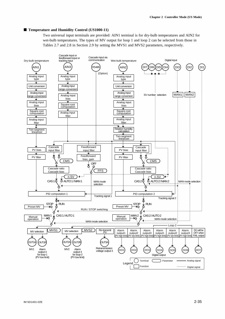
IM 5D1A01-02E 2-35
Chapter 2 Controller Mode (US Mode)
Temperature and Humidity Control (US1000-11)Two universal input terminals are provided: AIN1 terminal is for dry-bulb temperatures and AIN2 forwet-bulb temperatures. The types of MV output for loop 1 and loop 2 can be selected from those inTables 2.7 and 2.8 in Section 2.9 by setting the MVS1 and MVS2 parameters, respectively.
OUT3AOUT1A OUT1R
Analog input range conversion
Analog input bias
Square-root computation
Analog input filter
Ten-segment linearizer
Dry-bulb temperature
Cascade input or feedforward input or tracking input
Cascade input via communication
MV selection MVS1
Unit conversion
MAN 1
Cascade ratioCascade bias
PID computation 1
AIN3AIN1
PV bias
PV filter
STOP
Cascade input filter
AUTO 1 / MAN 1n.SV
Analog input range conversion
Analog input bias
Square-root computation
Analog input filter
CMS
Feedforward input filter
Feedforward bias, gain
FFS
OFF
CAS 1 / AUTO 1
RUN
RUN / STOP switching
RS485
(Option) Analog input
type Analog input
type
CAS 1
OUT2A OUT2R
MVS2
Analog input range conversion
Analog input bias
Square-root computation
Analog input filter
Ten-segment linearizer
Wet-bulb temperature
Unit conversion
MAN 2
Cascade ratioCascade bias
PID computation 2
AIN2
PV bias
PV filter
STOP
Cascade input filter
AUTO 2 / MAN 2n.SV
CMS
CAS 2 / AUTO 2
RUN
Analog input type
CAS 2
Relative humidity calculation
MAN mode selection
MAN mode selection
MAN mode selection
Tracking signal 1Tracking signal 2
Retransmission voltage output 3
MV selection
Preset MV
Manualoperation
Preset MV
Manualoperation
MV2MV1 DO3 DO4DO2 DO6 DO7DO5DO1
Re-transmitPV
DO will beOFF whenFAIL output
LegendTerminal
Function
Parameter Analog signal
Digital signal
Digital output
Alarm output1
(PV high limit)
Alarm output2
(PV low limit)
Alarm output3
(PV high limit)
SV number selection
DI7 DI6 DI5 DI4 DI3 DI2 DI1
Digital input
MAN1 MAN2
MAN mode selection
Alarm output1
(PV high limit)
Alarm output2
(PV low limit)
Alarm output3
(PV high limit)
Loop-2
Alarmoutput 4for loop-1
(PV low limit)
Alarmoutput 4for loop-2
(PV low limit)
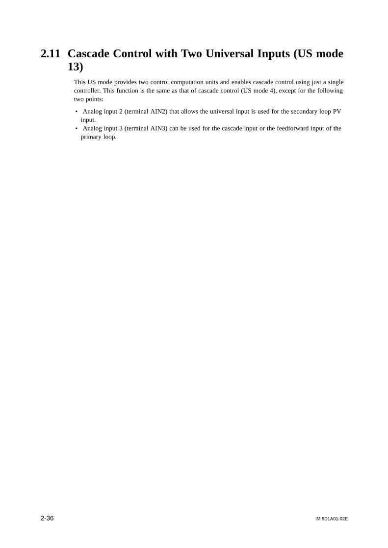
IM 5D1A01-02E2-36
2.11 Cascade Control with Two Universal Inputs (US mode13)
This US mode provides two control computation units and enables cascade control using just a singlecontroller. This function is the same as that of cascade control (US mode 4), except for the followingtwo points:
• Analog input 2 (terminal AIN2) that allows the universal input is used for the secondary loop PVinput.
• Analog input 3 (terminal AIN3) can be used for the cascade input or the feedforward input of theprimary loop.
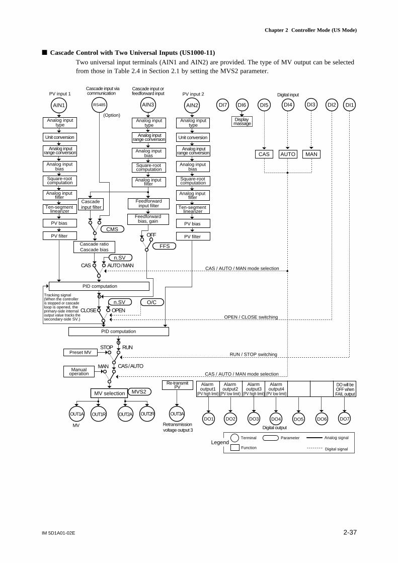
IM 5D1A01-02E 2-37
Chapter 2 Controller Mode (US Mode)
Cascade Control with Two Universal Inputs (US1000-11)Two universal input terminals (AIN1 and AIN2) are provided. The type of MV output can be selectedfrom those in Table 2.4 in Section 2.1 by setting the MVS2 parameter.
OUT3AOUT1A OUT1R OUT2A OUT2R
Analog input range conversion
Analog input bias
Square-root computation
Analog input filter
Ten-segment linearizer
PV input 1Cascade input orfeedforward input
MVS2
Unit conversion
MAN
AIN3AIN1
STOP
AUTO / MANn.SV
DI3 DI2 DI1DI7 DI6 DI5 DI4
CMS
FFS
OFF
CAS / AUTO
RUN
OPEN / CLOSE switching
CAS
RS485 AIN2
n.SV
OPENCLOSE
O/C
CAS / AUTO / MAN mode selection
RUN / STOP switching
CAS / AUTO / MAN mode selection
Retransmission voltage output 3
MV
MV selection
PID computation
PID computation
Cascade ratioCascade bias
PV bias
PV filter
Feedforward input filter
Feedforward bias, gain
Cascade input filter
Analog input type
Analog input range conversion
Analog input bias
Square-root computation
Analog input filter
Analog input type
Analog input range conversion
Analog input bias
Square-root computation
Analog input filter
Ten-segment linearizer
Unit conversion
Analog input type
(Option)
Cascade input via communication PV input 2
PV bias
PV filter
Preset MV
Manualoperation
DO3 DO4DO2 DO6 DO7DO5DO1
Re-transmitPV DO will be
OFF whenFAIL output
LegendTerminal
Function
Parameter Analog signal
Digital signal
Digital output
Alarm output1
(PV high limit)
Alarm output2
(PV low limit)
Alarm output3
(PV high limit)
Alarm output4
(PV low limit)
Display massage
MANCAS AUTO
Digital input
Tracking signal(When the controlleris stopped or cascadeloop is opened, theprimary-side internaloutput value tracks thesecondary-side SV.)

IM 5D1A01-02E2-38
Cascade Control with Two Universal Inputs (US1000-21)Control is performed based on a position-proportional PID computation so as to ensure that the MVoutput and control valve opening always match. Two universal input terminals (AIN1 and AIN2) areprovided. The MV output is a position-proportional control relay output (OUTR terminal). A valveposition feedback input is provided.
OUT3A
MAN
AIN3AIN1
STOP
AUTO / MANn.SV
DI3 DI2 DI1DI7 DI6 DI5 DI4
CMS
FFS
OFF
CAS / AUTO
RUN
OPEN / CLOSE switching
CAS
RS485 AIN2
n.SV
OPENCLOSE
O/C
RUN / STOP switching
OUTR OUT1AFBIN
CAS / AUTO / MAN mode selection
Retransmissionvoltage output 3
PID computation
PID computation
Cascade ratioCascade bias
Cascade input filter
Analog input range conversion
Analog input bias
Square-root computation
Analog input filter
Ten-segment linearizer
Unit conversion
PV bias
PV filter
Analog input type
PV input 1
(Option)
Cascade input via communication
Cascade input orfeedforward input
Feedforward input filter
Feedforward bias, gain
Analog input range conversion
Analog input bias
Square-root computation
Analog input filter
Analog input type
PV input 2
Analog input range conversion
Analog input bias
Square-root computation
Analog input filter
Ten-segment linearizer
Unit conversion
Analog input type
PV bias
PV filter
Valve position feedback input
Retransmissioncurrent output 1
CAS / AUTO / MAN mode selection
Preset MV
Manualoperation
DO3 DO4DO2 DO6 DO7DO5DO1
Re-transmitPV
Re-transmitMV
DO will beOFF whenFAIL output
LegendTerminal
Function
Parameter Analog signal
Digital signal
Digital output
Alarm output1
(PV high limit)
Alarm output2
(PV low limit)
Alarm output3
(PV high limit)
Alarm output4
(PV low limit)
Positionproportionalcontrol relay
output
Display massage
MANCAS AUTO
Digital input
Tracking signal(When the controlleris stopped or cascadeloop is opened, theprimary-side internaloutput value tracks thesecondary-side SV.)

IM 5D1A01-02E 2-39
Chapter 2 Controller Mode (US Mode)
2.12 Loop Control with PV Switching and Two UniversalInputs (US mode 14)
This US mode provides a control function that switches between two PV inputs by either a contactinput signal or according to a PV range. The function is the same as that of loop control with PVswitching (US mode 6), except for the following two points:
• Analog input 2 (terminal AIN2) that allows the universal input is used for PV input 2.• Analog input 3 (terminal AIN3) can be used for cascade input, feedforward input, or tracking
input.
When using a tracking input, a tracking flag function must be assigned to a contact input (DI). Forinformation about contact input assignment, refer to Section 3.15, “Parameters for Contact Input.”
The method of PV switching and the PV range for switching are specified with the following USERparameters.
Table 2.9 USER Parameters for Loop Control with PV Switching and Two UniversalInputs
Range of settingDescriptionSubmenu DefaultMain menu
USR –
Parameter
U1 USER parameter 1 PV upper limit for PV switching 0
U2 USER parameter 2 PV lower limit for PV switching 0
U3 USER parameter 3
Switching condition0: Switching within the PV range specified by U1 and U21: Switching at the PV upper limit specified by U12: Switching by contact input
0
See Also Section 2.6, “Loop Control with PV Switching,” for information about the USER parameter 3.
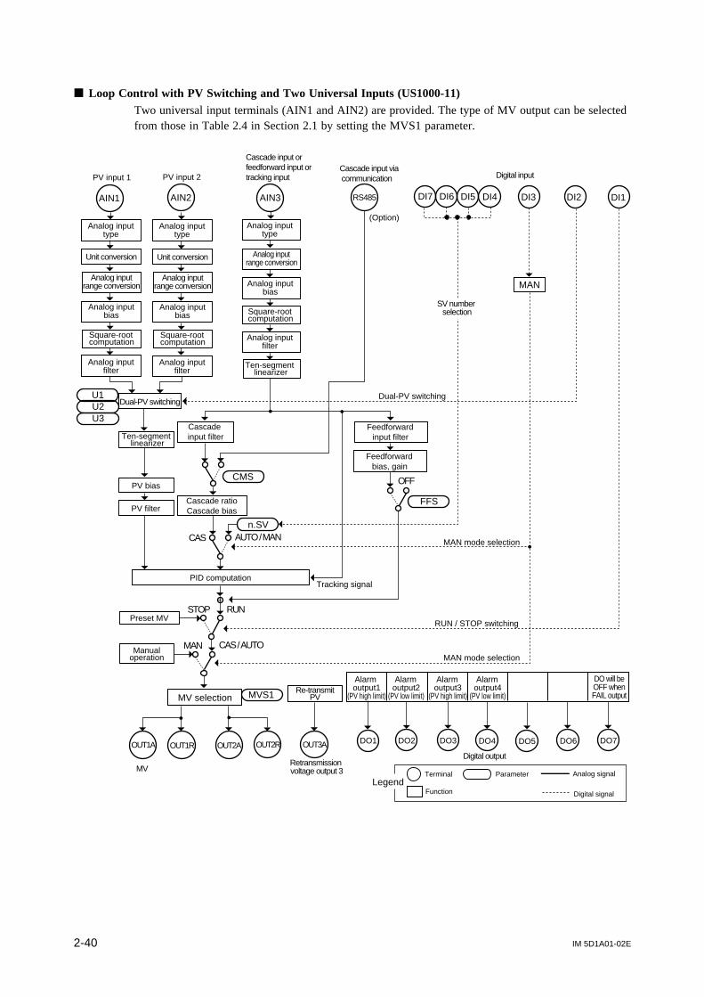
IM 5D1A01-02E2-40
Loop Control with PV Switching and Two Universal Inputs (US1000-11)Two universal input terminals (AIN1 and AIN2) are provided. The type of MV output can be selectedfrom those in Table 2.4 in Section 2.1 by setting the MVS1 parameter.
OUT3AOUT1A OUT1R OUT2A OUT2R
MVS1
MAN
AIN2AIN1
PV bias
PV filter
STOP
Cascade input filter
AUTO / MANn.SV
DI3 DI2 DI1
CMS
Feedforward input filter
Feedforward bias, gain
FFS
OFF
CAS / AUTO
RUN
RS485
Dual-PV switchingU1U2U3
Cascade input orfeedforward input ortracking input
AIN3
CAS
Retransmission voltage output 3MV
MV selection
PID computationTracking signal
RUN / STOP switching
MAN mode selection
MAN mode selection
Cascade ratioCascade bias
Ten-segment linearizer
Ten-segment linearizer
Analog input range conversion
Analog input bias
Square-root computation
Analog input filter
Unit conversion
Analog input type
Analog input range conversion
Analog input bias
Square-root computation
Analog input filter
Unit conversion
Analog input type
Analog input range conversion
Analog input bias
Square-root computation
Analog input filter
Analog input type
PV input 1 PV input 2
(Option)
Cascade input via communication
Preset MV
Manualoperation
DO3 DO4DO2 DO6 DO7DO5DO1
Re-transmitPV
DO will beOFF whenFAIL output
LegendTerminal
Function
Parameter Analog signal
Digital signal
Digital output
Alarm output1
(PV high limit)
Alarm output2
(PV low limit)
Alarm output3
(PV high limit)
Alarm output4
(PV low limit)
DI7 DI6 DI5 DI4
Digital input
MAN
Dual-PV switching
SV number selection

IM 5D1A01-02E 2-41
Chapter 2 Controller Mode (US Mode)
Loop Control with PV Switching and Two Universal Inputs (US1000-21)Control is performed based on a position-proportional PID computation so as to ensure that the MVoutput and control valve opening always match. Two universal input terminals (AIN1 and AIN2) areprovided. The MV output is a position-proportional control relay output (OUTR terminal). A valveposition feedback input is provided.
OUT3A
MAN
AIN2AIN1
STOP
AUTO / MANn.SV
CMS
FFS
OFF
CAS / AUTO
RUN
MAN mode selection
RS485
Dual-PV switching
Tracking signal
MAN mode selection
U1U2U3
Cascade input or feedforward input or tracking input
AIN3
CAS
OUTR OUT1AFBIN
RUN / STOP switching
SV number selection
Retransmission voltage output 3
Retransmission current output 1
Valve position feedback input
PID computation
PV bias
PV filterCascade ratioCascade bias
Cascade input filterTen-segment
linearizer
Feedforward input filter
Feedforward bias, gain
PV input 1 PV input 2
Square-root computation
Analog input bias
Unit conversion
Analog input range conversion
Analog input filter
Analog input type
Square-root computation
Analog input bias
Unit conversion
Analog input range conversion
Analog input filter
Analog input type
Square-root computation
Analog input bias
Analog input range conversion
Analog input filter
Ten-segment linearizer
Analog input type
Cascade input via communication
(Option)
Preset MV
Manualoperation
DO3 DO4DO2 DO6 DO7DO5DO1
Re-transmitPV
Re-transmitMV
DO will beOFF whenFAIL output
LegendTerminal
Function
Parameter Analog signal
Digital signal
Digital output
Alarm output1
(PV high limit)
Alarm output2
(PV low limit)
Alarm output3
(PV high limit)
Alarm output4
(PV low limit)
Positionproportionalcontrol relay
output
DI3 DI2 DI1DI7 DI6 DI5 DI4
Digital input
MAN
Dual-PV switching

IM 5D1A01-02E2-42
2.13 Loop Control with PV Auto-selector and Two Univer-sal Inputs (US mode 15)
This US mode allows a total of three PV inputs to be used æ two universal inputs and one analoginput. It provides a control function that automatically selects either the largest or smallest value orsets the average value of two or three PV input values, or difference between the PV input values, asthe PV input.
The function is the same as that of loop control with PV auto-selector (US mode 7), except for thefollowing two points:
• Analog input 2 (terminal AIN2) that allows the universal input is used for PV input 2.• Analog input 3 (terminal AIN3) can be used for PV input 3, cascade input, feedforward input, or
tracking input. To use this terminal for PV input 3, set USER parameter 2 (U2) to 1.
When using a tracking input, a tracking flag function must be assigned to a contact input (DI). Forinformation about contact input assignment, refer to Section 3.15, “Parameters for Contact Input.”
The selection of PV is carried out according to the following USER parameters.
Table 2.10 USER Parameters for Loop Control with PV Auto-selector and Two UniversalInputs
Range of settingDescriptionSubmenu DefaultMain menu
USR –
Parameter
U1 USER parameter 1
Input selection0: Accepts the maximum value between inputs 1, 2 (and 3)1: Accepts the minimum value between inputs 1, 2 (and 3)2: Accepts the average value of inputs 1, 2 (and 3)3: Accepts the difference between input 1 and input 2
(i.e., input 2 - input 1)
2
U2 USER parameter 20: Uses two points (inputs 1 and 2)1: Uses three points (inputs 1, 2 and 3) 0

IM 5D1A01-02E 2-43
Chapter 2 Controller Mode (US Mode)
Loop Control with PV Auto-selector and Two Universal Inputs (US1000-11)Two universal input terminals (AIN1 and AIN2) are provided. The type of MV output can be selectedfrom those in Table 2.4 in Section 2.1 by setting the MVS1 parameter.
PV input 2
PV input 3 or cascadeinput or feedforward input ortracking input
U2
U1 Input selection
PV3
AIN3AIN1 AIN2
CMS
+
MVS1
STOP RUN
MAN CAS / AUTO
OUT3AOUT1A OUT1R OUT2A OUT2R
FFS
n.SV
Tracking signal
AUTO / MAN
OFF
CAS
RS485
MV
MV selection
PID computation
Retransmission voltage output 3
RUN / STOP switching
AUTO mode selection or MAN mode selection
AUTO mode selection or MAN mode selection
SV number selection
Feedforward input filter
Feedforward bias, gainCascade
input filter
Cascade ratioCascade bias
Ten-segment linearizer
PV bias
PV filter
Analog input range conversion
Analog input bias
Square-root computation
Analog input filter
Unit conversion
Analog input type
Analog input range conversion
Analog input bias
Square-root computation
Analog input filter
Unit conversion
Analog input type
Analog input range conversion
Analog input bias
Square-root computation
Analog input filter
Analog input type
PV input 1
(Option)
Cascade input via communication
Preset MV
Manualoperation
DO3 DO4DO2 DO6 DO7DO5DO1
Re-transmitPV
DO will beOFF whenFAIL output
LegendTerminal
Function
Parameter Analog signal
Digital signal
Digital output
Alarm output1
(PV high limit)
Alarm output2
(PV low limit)
Alarm output3
(PV high limit)
Alarm output4
(PV low limit)
DI3 DI2 DI1DI7 DI6 DI5 DI4
Digital input
AUTO MAN

IM 5D1A01-02E2-44
Loop Control with PV Auto-selector and Two Universal Inputs (US1000-21)Control is performed based on a position-proportional PID computation so as to ensure that the MVoutput and control valve opening always match. Two universal input terminals (AIN1 and AIN2) areprovided. The MV output is a position-proportional control relay output (OUTR terminal). A valveposition feedback input is provided.
U2
U1
DI3 DI2 DI1AIN3AIN1 AIN2
CMS
+STOP RUN
MAN CAS/AUTO
OUT3A
FFS
n.SV
CAS/AUTO
OFF
CAS
RS485
OUTR OUT1AFBIN
Retransmission voltage output 3
Retransmission current output 1
Valve position feedback input
Tracking signal
SV number selection
AUTO mode selection or MAN mode selection
RUN / STOP switching
AUTO mode selection or MAN mode selection
Feedforward input filter
Feedforward bias, gain
PID computation
Cascade ratioCascade bias
Cascade input filter
Ten-segment linearizer
PV bias
PV filter
Inputselection
Analog input range conversion
Analog input bias
Square-root computation
Analog input filter
Unit conversion
Analog input type
Analog input range conversion
Analog input bias
Square-root computation
Analog input filter
Unit conversion
Analog input type
PV input 1 PV input 2
PV input 3 or cascadeinput or feedforward input ortracking input Cascade input via
communication
(Option)
PV 3
Analog input range conversion
Analog input bias
Square-root computation
Analog input filter
Analog input type
Preset MV
Manualoperation
DO3 DO4DO2 DO6 DO7DO5DO1
Re-transmitPV
Re-transmitMV
DO will beOFF whenFAIL output
LegendTerminal
Function
Parameter Analog signal
Digital signal
Digital output
Alarm output1
(PV high limit)
Alarm output2
(PV low limit)
Alarm output3
(PV high limit)
Alarm output4
(PV low limit)
DI7 DI6 DI5 DI4
Digital input
AUTO MAN
Positionproportionalcontrol relay
output

IM 5D1A01-02E 2-45
Chapter 2 Controller Mode (US Mode)
2.14 Custom Computation Control (US mode 21)This US mode allows users to customize input and output computations, signal assignments, andoperation displays. To use the custom computation function, the optional LL1200 PC-based CustomComputation Building Tool is necessary. The tool includes the LL1100 PC-based Parameters SettingTool, which is used to set the parameters of the US1000 controller from a personal computer.
Main Specifications of Custom Computation FunctionProvided computation modules:
Basic four arithmetical operations, logical operations, ten-segment linearizer approximation,temperature and humidity calculation, temperature compensation, pressure compensation, andothers.
Customization of operation displays:Customizing display types, the display sequence, and display conditions, is possible.

Blank Page

IM 5D1A01-02E 3-1
Chapter 3 Parameters
3. Parameters
The US1000 controller has two kinds of parameters: “Setup Parameters,” which are used to configurefunctions, and “Operation Parameters,” which are used for operation.This chapter describes all of these parameters. (However, refer to Chapter 2 for USM parameters.)
Regarding Tables in This Chapter
Main Sub Parameter Description Range of setting Default
Main menu code to which the parameter belongs
The information contained in the brackets above the table is the setup parameter or operation parameter.
Submenu code to which the parameter belongs
Parameter code
[ ] Brief description Factory-set value
Setting range or selection alternatives of the parameter(For EU and EUS, refer to "Appendix 2" in the separateinstruction manual "US1000 Digital Indicating Controller"(IM 5D1A01-01E).)
Parameters of the same function are distinguished by the number in their parameter codes.For example: RH1, RH2, RH3In this chapter, these parameters are expressed by one code with the numbers represented as “n” forconvenience sake.For example: RHn
See Also Some parameters are not displayed depending on the controller model and controller mode (US
mode). For information on parameter call-up and setting operations, refer to the separate instruction manual
“US1000 Digital Indicating Controller” (IM 5D1A01-01E).

IM 5D1A01-02E3-2
3.1 Parameters that Determine the Action at Power-onand Power Recovery
A momentary power failure of less than 20 ms has no effect on the controller action. (The controllercontinues to operate normally.)Following a power failure that lasts for 20 ms or longer however, the controller will operate asdescribed below upon a power recovery (see Figure 3.1.1).
Time of power failure20 ms 2 s
Powerfailure
deadband
Momentarypower failure Power failure
Operationcontinues
• Parameter settings are maintained.• Alarms with waiting action return to a waiting status.• Auto-tuning is canceled.
• R.MD = HOT: Operation mode and MV continue.• R.MD = COLD: Starts from a preset output value
in MAN mode.
Figure 3.1.1 Time of Power Failure and Operation Upon Power Recovery
• Alarm action: Continues. But the alarms with waiting action immediately return to waitingstatus (Refer to subsection 3.14.1, “Alarm Types.”)
• Parameter settings: Maintained.• Auto-tuning: Canceled.• Control action: The operation prior to the power failure continues when the power failure is less
than 2 seconds. The operation varies according to the parameter R.MD settingwhen the failure lasts for 2 seconds or longer.
[Setup parameter]
Main Sub Parameter Description Setting Range Default
CMLP C.CTLR.MD Restart mode
HOT: Continues the operation prior to power failureCOLD: Starts in MAN mode
R.TM Restart timer 0 to 60 s 0 s
COLD
R.MD setpoint Control action after recovery
HOT Operation mode and MV continue after recovery.
COLDStarts in MAN (manual operation) after recovery. MV is reset to the preset MV value (‘n.PM’ of operation parameters).
Parameter R.TM is used to delay the start of the controller’s operation by a specified period of time,after the power is turned on. R.TM is used in cases where the controller should start up after the otherequipment.
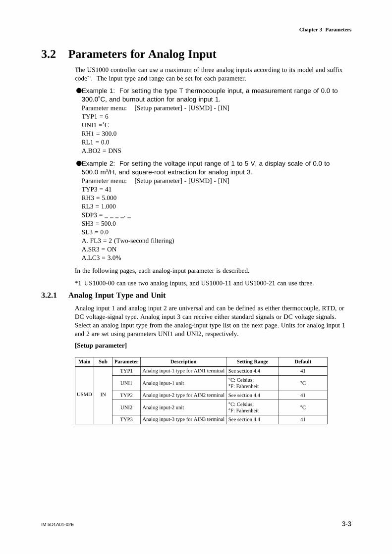
IM 5D1A01-02E 3-3
Chapter 3 Parameters
3.2 Parameters for Analog InputThe US1000 controller can use a maximum of three analog inputs according to its model and suffixcode*1. The input type and range can be set for each parameter.
Example 1: For setting the type T thermocouple input, a measurement range of 0.0 to300.0˚C, and burnout action for analog input 1.Parameter menu: [Setup parameter] - [USMD] - [IN]TYP1 = 6UNI1 =˚CRH1 = 300.0RL1 = 0.0A.BO2 = DNS
Example 2: For setting the voltage input range of 1 to 5 V, a display scale of 0.0 to500.0 m3/H, and square-root extraction for analog input 3.Parameter menu: [Setup parameter] - [USMD] - [IN]TYP3 = 41RH3 = 5.000RL3 = 1.000SDP3 = _ _ _ _. _SH3 = 500.0SL3 = 0.0A. FL3 = 2 (Two-second filtering)A.SR3 = ONA.LC3 = 3.0%
In the following pages, each analog-input parameter is described.
*1 US1000-00 can use two analog inputs, and US1000-11 and US1000-21 can use three.
3.2.1 Analog Input Type and Unit
Analog input 1 and analog input 2 are universal and can be defined as either thermocouple, RTD, orDC voltage-signal type. Analog input 3 can receive either standard signals or DC voltage signals.Select an analog input type from the analog-input type list on the next page. Units for analog input 1and 2 are set using parameters UNI1 and UNI2, respectively.
[Setup parameter]
Main Sub Parameter Description Setting Range Default
USMD IN
TYP1 Analog input-1 type for AIN1 terminal See section 4.4 41
UNI1 Analog input-1 unit°C: Celsius;°F: Fahrenheit
°C
TYP2 Analog input-2 type for AIN2 terminal See section 4.4 41
UNI2 Analog input-2 unit°C: Celsius;°F: Fahrenheit
°C
TYP3 Analog input-3 type for AIN3 terminal See section 4.4 41

IM 5D1A01-02E3-4
Table Analog Input Types
Input type Setting Range (°C) Range (°F) Accuracy
Thermocouple K 1 -270.0 to 1370.0C -450.0 to 2500.0°F 0C and over: 0.1% of F.S.
2 -270.0 to 1000.0C -450.0 to 2300.0°F Below 0C : 0.2% of F.S.
3 -200.0 to 500.0C -200.0 to 1000.0°F K (below -200C) : 2% of F.S.
J 4 -200.0 to 1200.0C -300.0 to 2300.0°F
T 5 -270.0 to 400.0C -450.0 to 750.0°F T (below -200C) : 1% of F.S.
6 0.0 to 400.0C -200.0 to 750.0°F
B 7 0.0 to 1800.0C 32 to 3300°F 400C and over: 0.1% of F.S.
Below 400C : 5% of F.S.
S 8 0.0 to 1700.0C 32 to 3100°F 0.15% of F.S.
R 9 0.0 to 1700.0C 32 to 3100°F
N 10 -200.0 to 1300.0C -300.0 to 2400.0°F 0.1% of F.S.
E 11 -270.0 to 1000.0C -450.0 to 1800.0°F 0C and over: 0.1% of F.S.
L 12 -200.0 to 900.0C -300.0 to 1600.0°F Below 0C : 0.2% of F.S.
U 13 -200.0 to 400.0C -300.0 to 750.0°F E (below -200C) : 1.5% of F.S.
14 0.0 to 400.0C -200.0 to 1000.0°F 0.2% of F.S.
W 15 0.0 to 2300.0C 32 to 4200°F 0.2% of F.S.
Platinel 2 16 0.0 to 1390.0C 32.0 to 2500.0°F 0.1% of F.S.
PR20-40 17 0.0 to 1900.0C 32 to 3400°F 800C and over: 0.5% of F.S.
Below 800C : Accuracy not guaranteed
W97Re3 18 0.0 to 2000.0C 32 to 3600°F 0.2% of F.S.
W75Re25
RTD JPt100 30 -200.0 to 500.0C -300.0 to 1000.0°F 0.1% of F.S.
31 -150.00 to 150.00C -200.0 to 300.0°F 0.2% of F.S.
Pt100 35 -200.0 to 850.0C -300.0 to 1560.0°F 0.1% of F.S.
(ITS90) 36 -200.0 to 500.0C -300.0 to 1000.0°F
37 -150.00 to 150.00C -200.0 to 300.0°F 0.2% of F.S.
Standard signal 0.4 to 2.0 V 40 0.400 to 2.000 0.1% of F.S.
1 to 5 V 41 1.000 to 5.000
DC voltage 0 to 2 V 50 0.000 to 2.000
0 to 10 V 51 0.00 to 10.00
-10 to 20mV 55 -10.00 to 20.00
0 to 100mV 56 0.0 to 100.0

IM 5D1A01-02E 3-5
Chapter 3 Parameters
3.2.2 Analog Input Range and PV Range
[Setup parameter]
Main Sub Parameter Description Setting Range Default
USMD IN
RH1Maximum value of analog input-1 range
Within instrument input range
Maximum level of instrument range
RL1Minimum value of analog input-1 range
Within instrument input range
Minimum level of instrument range
RH2Maximum value of analog input-2 range
Within instrument input range
Maximum level of instrument range
RL2Minimum value of analog input-2 range
Within instrument input range
Minimum level of instrument range
RH3Maximum value of analog input-3 range
Within instrument input range
5.000
RL3Minimum value of analog input-3 range
Within instrument input range
1.000
P.RH1 Maximum value of PV1 range-19999 to 30000, 0<P.RH1-P.RL1≤30000
Thermocouple, RTD: RH1 value; voltage input: 100.0
P.RL1 Minimum value of PV1 range-19999 to 30000, 0<P.RH1-P.RL1≤30000
Thermocouple, RTD: RL1 value; voltage input: 0.0
P.RH2 Maximum value of PV2 range-19999 to 30000, 0<P.RH2-P.RL2≤30000
Thermocouple, RTD: RH2 value; voltage input: 100.0
P.RL2 Minimum value of PV2 range-19999 to 30000, 0<P.RH2-P.RL2≤30000
Thermocouple, RTD: RL2 value; voltage input: 0.0
Parameters RH1 to RL3 are used to set the range used for control within the instrument range shownin the analog-input type list on the previous page.
Parameters P.RH1 to P.RL2 (PV range) are used to set the PV ranges used for the controller’s internalcomputation when the controller performs loop control with PV switching or loop control with PVauto-selector which receives two inputs of different measurement ranges (see Figure 3.2.1). Theparameters are also used to set the PV range for relative humidity data obtained from dry- and wet-bulb calculations in temperature and humidity control (see Figure 3.2.2).The decimal point position of the PV range can be set with parameters P.DP1 and P.DP2 (refer tosubsection 3.2.3).
0 300 500 1000 °C
Range of analog input 1
Range of analog input 2
PV rangeP.RL1
RL1 RH1
RL2 RH2
P.RH1
Figure 3.2.1 PV Range for a Control Having More than One Input

IM 5D1A01-02E3-6
Dry- and wet-bulbcalculation
Dry bulb (Input 1)-50 to 100°C
Wet bulb (Input 2)-50 to 100°C
PV230.0 to 100.0%
PV1-50 to 100°C
PV range conversion
Sets • _ _ _ _. _ for P.DP2,• 100.0 for P.RH2, and• 30.0 for P.RL2.
Figure 3.2.2 PV Range for Temperature and Humidity Control
3.2.3 Decimal Point Position of Analog Input
Parameters SDP1 to SDP3 are used to set the decimal point positions of analog inputs. These param-eters can be set only for standard signal and DC voltage-signal inputs. As for thermocouple and RTDinputs, the decimal point positions of the instrument ranges listed in the analog-input type table insubsection 3.2.1 apply.
P.DP1 and P.DP2 are the parameters that set the decimal point positions of PV1 and PV2, which areused in the internal computation of the controller. (Refer to subsection 3.2.2, “Analog Input Range andPV Range.”)
[Setup parameter]
Main Sub Parameter Description Setting Range Default
USMD IN
SDP1 Analog input-1 decimal point position 0 to 4 *1 1
SDP2 Analog input-2 decimal point position 0 to 4 *1 1
SDP3 Analog input-3 decimal point position 0 to 4 *1 1
P.DP1 PV1 decimal point position 0 to 4 *1 1
P.DP2 PV2 decimal point position 0 to 4 *1 1
* The parameter settings in the table above are displayed with under bars “_” and a period “.”. For example, “_ _ _ _. _” is thedisplay shown when the setting of SDP1 is 1.
3.2.4 Display Scale of Analog Input
When the analog input type is specified as a standard signal or DC voltage signal, the PV input signalis in voltage. In this case, the range of the voltage signal can be prescribed with parameters RHn andRLn (Refer to subsection 3.2.2, “Analog Input Range and PV Range.”). However, the signal stillneeds to be converted to the physical quantity unit of the controlled object. SHn and SLn are theparameters used to carry out this conversion. The signal is converted into the physical quantity unit ofthe controlled object, which is a display scale. The number of decimal places can be set with param-eter SDPn (Figure 3.2.3). (Refer to subsection 3.2.3, “Decimal Point Position of Analog Input.”)

IM 5D1A01-02E 3-7
Chapter 3 Parameters
[Setup parameter]
Main Sub Parameter Description Setting Range Default
USMD IN
SH1Maximum value of analog input-1 scale
-19999 to 30000, SL1<SH1
100.0
SL1Minimum value of analog input-1 scale
-19999 to 30000, SL1<SH1
0.0
SH2Maximum value of analog input-2 scale
-19999 to 30000, SL2<SH2
100.0
SL2Minimum value of analog input-2 scale
-19999 to 30000, SL2<SH2
0.0
SH3Maximum value of analog input-3 scale
-19999 to 30000, SL3<SH3
100.0
SL3Minimum value of analog input-3 scale
-19999 to 30000, SL3<SH3
0.0
1 V 2 V 4 V 5 V
Display scale default
Analog input range
Instrument range
Display scale
2.000 V (RLn) 4.000V (RHn)
0.0 (SLn) 100.0 (SHn)
10.00 (SLn) 50.00 (SHn)
(a)
(a) When the input type is set at "41," the instrument range is 1.000 to 5.000 V.(b) In this example, the analog input range is set as 2.000 to 4.000 V using parameters RLn and RHn.(c) The default of the display scale is 0.0 to 100.0.(d) Parameters SDPn, SHn, and SLn have been set to _ _ _. _ _, 50.00, and 10.00, respectively.
(b)
(c)
(d)
Figure 3.2.3 Setting Input Scale
3.2.5 Analog Input Bias (Normally used at default)
This biasing is used to correct sensor-input characteristics, compensating lead wire errors, and so on.The analog input biasing is similar to the PV biasing described in subsection 3.3.1.Corrected analog input value = Analog input value + Analog input bias
[Setup parameter]
Main Sub Parameter Description Setting Range Default
CMPL AIN
A.BS1 Analog input-1 bias EUS (-100.0 to 100.0%) EUS (0%)
A.BS2 Analog input-2 bias EUS (-100.0 to 100.0%) EUS (0%)
A.BS3 Analog input-3 bias EUS (-100.0 to 100.0%) EUS (0%)
3.2.6 Analog Input Filter (Normally used at default)
The analog input filter is used to remove noise from a PV input signal that contains high frequencynoises such as flow rate and pressure signals. The filter provides a first-order-lag calculation, whichcan remove more noise the larger time constant becomes (see Figure 3.2.4). However, an excessivelylarge time constant will distort the waveform.The analog input filter is similar to the PV filter described in subsection 3.3.2. Normally, the PV inputfilter is used, but in cases where a constant level of correction is required, such as in an environmentthat contains a lot of noise, the analog input filter should be used.

IM 5D1A01-02E3-8
[Setup parameter]
Main Sub Parameter Description Setting Range Default
CMPL AIN
A.FL1 Analog input-1 filter OFF, 1 to 120 s OFF
A.FL2 Analog input-2 filter OFF, 1 to 120 s OFF
A.FL3 Analog input-3 filter OFF, 1 to 120 s OFF
Actual input With the proper time constant With an excessively largetime constant
Figure 3.2.4 Image of Measured Signal Correction by Analog Input Filters
3.2.7 Square-root Extraction
This calculation is used to convert a differential pressure signal from a throttling flow meter such asan orifice and nozzle. Low signals are cut off at the point specified by parameter A.LCn.The slope below the lowcut point is fixed at 1.
[Setup parameter]
Main Sub Parameter Description Setting Range Default
CMPL AIN
A.SR1 Analog input-1 square-root computation OFF, ON OFF
A.LC1 Analog input-1 square-root low signal cut off 0.0 to 5.0% 1.0%
A.SR2 Analog input-2 square-root computation OFF, ON OFF
A.LC2 Analog input-2 square-root low signal cut off 0.0 to 5.0% 1.0%
A.SR3 Analog input-3 square-root computation OFF, ON OFF
A.LC3 Analog input-3 square-root low signal cut off 0.0 to 5.0% 1.0%
Input
Input valueafter square-root
extraction
Lowcut point (0.0-5.0%)
100.0%
100.0%0.0%
Slope = 1
Figure 3.2.5 Square-root Extraction

IM 5D1A01-02E 3-9
Chapter 3 Parameters
3.2.8 Action at a Burnout
For thermocouple, RTD, and standard signal inputs, the action at a burnout can be specified to eachinput.When upscale is specified, PV = 105.0% and MV = preset MV value (operation parameter n.PM).When downscale is specified, PV = -5.0% and MV = preset MV value (operation parameter n.PM).
[Setup parameter]
Main Sub Parameter Description Setting Range Default
CMPL AIN
OFF: DisabledA.BO1 Analog input-1 burnout action UPS: Upscale OFF
DNS: Downscale
OFF: DisabledA.BO2 Analog input-2 burnout action UPS: Upscale OFF
DNS: Downscale
OFF: DisabledA.BO3 Analog input-3 burnout action UPS: Upscale OFF
DNS: Downscale
3.2.9 Reference Junction Compensation for Analog Input
The US1000 controller has a reference junction compensation function for the thermocouple inputs ofanalog input 1 and 2. When an external device is used for reference junction compensation (0 °C), setparameter A.RJn to OFF.
[Setup parameter]
Main Sub Parameter Description Setting Range Default
CMPL AINA.RI1 Analog input-1 reference junction compensation OFF, ON ON
A.RJ2 Analog input-2 reference junction compensation OFF, ON ON
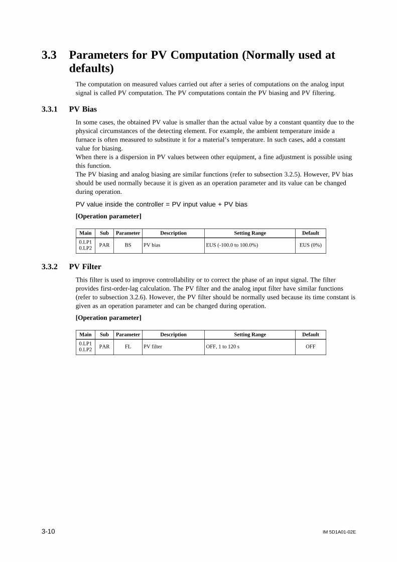
IM 5D1A01-02E3-10
3.3 Parameters for PV Computation (Normally used atdefaults)
The computation on measured values carried out after a series of computations on the analog inputsignal is called PV computation. The PV computations contain the PV biasing and PV filtering.
3.3.1 PV Bias
In some cases, the obtained PV value is smaller than the actual value by a constant quantity due to thephysical circumstances of the detecting element. For example, the ambient temperature inside afurnace is often measured to substitute it for a material’s temperature. In such cases, add a constantvalue for biasing.When there is a dispersion in PV values between other equipment, a fine adjustment is possible usingthis function.The PV biasing and analog biasing are similar functions (refer to subsection 3.2.5). However, PV biasshould be used normally because it is given as an operation parameter and its value can be changedduring operation.
PV value inside the controller = PV input value + PV bias
[Operation parameter]
Main Sub Parameter Description Setting Range Default
BS PV bias EUS (-100.0 to 100.0%) EUS (0%)0.LP10.LP2
PAR
3.3.2 PV Filter
This filter is used to improve controllability or to correct the phase of an input signal. The filterprovides first-order-lag calculation. The PV filter and the analog input filter have similar functions(refer to subsection 3.2.6). However, the PV filter should be normally used because its time constant isgiven as an operation parameter and can be changed during operation.
[Operation parameter]
Main Sub Parameter Description Setting Range Default
FL PV filter OFF, 1 to 120 s OFF0.LP10.LP2
PAR

IM 5D1A01-02E 3-11
Chapter 3 Parameters
3.4 Parameters for Cascade Input
3.4.1 Selection of Cascade Input
The destination of cascade input can be specified using the CMS parameter. The signal from thecascade input destination is taken for the target setpoint (cascade setpoint) when the controller is inCAS mode.When the CMS parameter is set at AIN, the cascade input is the signal from the analog input terminal(AIN2 or AIN3). When it is set at CPT, the cascade input is the signal from RS-485 terminal.
[Setup parameter]
Main Sub Parameter Description Setting Range Default
S.LP1S.LP2
SV CMS Cascade input selectionAIN: Analog inputCPT: Communication
AIN
3.4.2 Cascade Input Filter
This filter performs a first-order-lag calculation on the cascade setpoint value from the analog inputterminal when the CMS parameter described in subsection 3.4.1 is set at AIN.This calculation is not performed on the cascade setpoint transmitted via RS-485 communication.
[Operation parameter]
Main Sub Parameter Description Setting Range Default
0.LP10.LP2
PAR CFL Cascade input filter OFF, 1 to 120 s OFF
3.4.3 Cascade Ratio and Cascade Bias
[Operation parameter]
Main Sub Parameter Description Setting Range Default
0.LP10.LP2
PARCRT Cascade ratio 0.001 to 9.999 1.000
CBS Cascade bias EUS (-100.0 to 100.0%) EUS (0%)
The ratio multiplication and bias addition given by the following expression can be performed on thecascade setpoint.
Cascade setpoint after computation = Cascade setpoint(CRT) + (CBS),where CRT represents the cascade ratio and CBS the cascade bias.

IM 5D1A01-02E3-12
3.4.4 OPEN/CLOSE Switchover for Internal Cascade Control
Cascade OPEN: The internal cascade loop (the primary and secondary loops inside a controller)is disconnected.
Cascade CLOSE: The internal cascade loop (the primary and secondary loops inside a controller)is connected.
[Operation parameter]
Main Sub Parameter Description Setting Range Default
MODE — O/C OPEN/CLOSE switchover CLOSE/OPEN CLOSE
OPEN/CLOSE switchover of an internal cascade loop is also possible using a contact input. Forinformation about this method, refer to Section 6.6 “OPEN/CLOSE Switchover of Cascade Loop” inthe separate instruction manual “US1000 Digital Indicating Controller” (IM 5D1A01-01E).
Note that the OPEN/CLOSE switchover by contact input takes priority over the switching by the O/Csetting parameter.
PID computation 1
PID computation 2
Primary-loop PV
Primary-loop SV
CLOSE OPEN
Secondary-loop PV
Secondary-loop SV
MV
Figure 3.4.1 Switching between Cascade OPEN and Cascade CLOSE

IM 5D1A01-02E 3-13
Chapter 3 Parameters
3.5 Parameters for Feedforward Input
Feedforward ControlIn the feedback control generally performed, the PID action works only after the effect of the distur-bance appears in PV. This delays the recovery to the normal state. When the disturbance can bemeasured however, the effect of the disturbance can be nullified by adding a corrective signal thatcorresponds to the degree of that disturbance, to the controller’s MV before the effect appears in thecontrolled process. This operation is called feedforward control.
For example, in the pH control illustrated in Figure 3.5.1, the flow of waste water is measured as thefeedforward input and added to the controller’s MV after passing through the feedforward gain andbiasing operation. This means that the quantity of the neutralizing solution can be controlled so as tonullify the effect of the waste water.
M
Gain, Bias
ControlWasteWater
FlowSignal
pHSensor
NeutralizingSolution
FeedforwardCompensation
+
Figure 3.5.1 Feedforward Control
3.5.1 Selection of Feedforward Input
NOTEWhen the FFS parameter is set at AIN, always set the CMS parameter (refer to subsection 3.4.1) toCPT in order to prevent the feedforward input from being acquired by the controller as a cascade inputwhen the key is pressed by mistake.Set the above even when the RS-485 communication function will not be used.
To use a feedforward input, set the FFS parameter at AIN. The use of feedforward input is howeverlimited by the model of the controller and controller mode (US mode). Check if a feedforward inputcan be assigned to any terminal referring to the function block diagrams in Chapter 2.
[Setup parameter]
Main Sub Parameter Description Setting Range Default
S.LP1 CTL FFS Feedforward input selection OFF = Disabled; AIN: Analog input OFF

IM 5D1A01-02E3-14
3.5.2 Feedforward Input Filter, Bias, and Gain
The gain, filtering, and biasing calculation given by the following expression can be provided on thefeedforward input.
MV = MVC + FF
FF = FGN 1 / (1 + FFL • S) FIN + FBI + FBO
where,
FF: Feedforward input after gain, filtering, and biasing calculationMV
C: MV obtained by feedback control
FGN
: Feedforward gainF
FL: Feedforward input filter
FIN
: Feedforward inputF
BI: Feedforward input bias
FBO
: Feedforward output bias
[Operation parameter]
Main Sub Parameter Description Setting Range Default
0.LP1 PAR
FGN Feedforward gain -9.999 to 9.999 1.000
FBI Feedforward input bias -100.0 to 100.0% 0.0%
FBO Feedforward output bias -999.9 to 999.9% 0.0%
FFL Feedforward input filter OFF, 1 to 120 s OFF
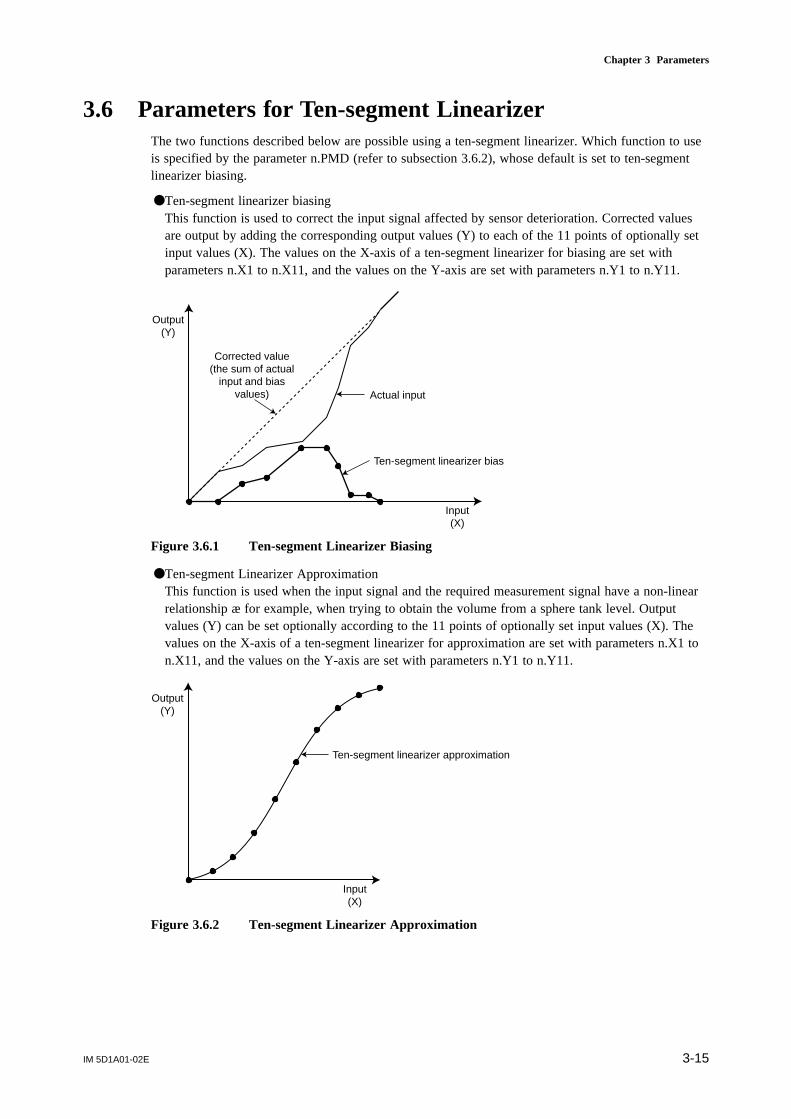
IM 5D1A01-02E 3-15
Chapter 3 Parameters
3.6 Parameters for Ten-segment LinearizerThe two functions described below are possible using a ten-segment linearizer. Which function to useis specified by the parameter n.PMD (refer to subsection 3.6.2), whose default is set to ten-segmentlinearizer biasing.
Ten-segment linearizer biasingThis function is used to correct the input signal affected by sensor deterioration. Corrected valuesare output by adding the corresponding output values (Y) to each of the 11 points of optionally setinput values (X). The values on the X-axis of a ten-segment linearizer for biasing are set withparameters n.X1 to n.X11, and the values on the Y-axis are set with parameters n.Y1 to n.Y11.
Input(X)
Output(Y)
Ten-segment linearizer bias
Actual input
Corrected value(the sum of actual
input and biasvalues)
Figure 3.6.1 Ten-segment Linearizer Biasing
Ten-segment Linearizer ApproximationThis function is used when the input signal and the required measurement signal have a non-linearrelationship æ for example, when trying to obtain the volume from a sphere tank level. Outputvalues (Y) can be set optionally according to the 11 points of optionally set input values (X). Thevalues on the X-axis of a ten-segment linearizer for approximation are set with parameters n.X1 ton.X11, and the values on the Y-axis are set with parameters n.Y1 to n.Y11.
Input(X)
Output(Y)
Ten-segment linearizer approximation
Figure 3.6.2 Ten-segment Linearizer Approximation

IM 5D1A01-02E3-16
3.6.1 Unit of Ten-segment Linearizer
Ten-segment linearizer 1 and 2 are used for loop-1 and loop-2, respectively.
[Setup parameter]
Main Sub Parameter Description Setting Range Default
CONF C. PYS
PY1XTen-segment linearizer-1 input unit
PY1YTen-segment linearizer-1 output unit
PY2XTen-segment linearizer-2 input unit
PY2Y
12
13
14
15Ten-segment linearizer-2 output unit
0: %, 1: ABS0, 2:ABS1, 3: ABS2,4: ABS3, 5: ABS4, 6: EU (AIN1),7: EUS (AIN1), 8: EU (AIN2), 9: EUS (AIN2), 10: EU (AIN3), 11: EUS (AIN3), 12: EU (PV1), 13: EUS (PV1), 14: EU (PV2), 15: EUS (PV2)
12: EU (PV1): The same engineering unit specified for loop-1 PV.13: EUS (PV1): The engineering unit that corresponds to the loop-1 PV range span.14: EU (PV2): The same engineering unit specified for loop-2 PV.15: EUS (PV2): The engineering unit that corresponds to the loop-2 PV range span.
For general use, use the defaults of the parameters for ten-segment linearizer biasing, and change thesettings of the parameters as follows for ten-segment linearizer approximation.PY1X: 12, PY1Y: 12, PY2X: 14, PY2Y: 14The values from 0 to 11 are used for the custom computation function. Do not set these values forgeneral use.
See Also Appendix 2 of the separate instruction manual “US1000 Digital Indicating Controller” (IM 5D1A01-01E), for the meanings of EU and EUS.
IM 5D1A01-02E 3-17
Chapter 3 Parameters
3.6.2 Parameters to Set Ten-segment Linearizer
These parameters set the inputs and outputs of a ten-segment linearizer for both biasing and approxi-mation. The parameters with n = 1 are for loop-1, and those with n = 2 are for loop-2. Parametern.PMD specifies the type of ten-segment linearizer.
[Operation parameter]
Main Sub Parameter Description Setting Range Default
PYSn(n=1, 2)
—
n. X1 Ten-segment linearizer-n input 1 EU (-66.7 to 105.0%) EU (0.0%)
n. Y1 Ten-segment linearizer-n output 1 EUS (-66.7 to 105.0%) EUS (0.0%)
n. X2 Ten-segment linearizer-n input 2 EU (-66.7 to 105.0%) EU (0.0%)
n. Y2 Ten-segment linearizer-n output 2 EUS (-66.7 to 105.0%) EUS (0.0%)
n. X3 Ten-segment linearizer-n input 3 EU (-66.7 to 105.0%) EU (0.0%)
n. Y3 Ten-segment linearizer-n output 3 EUS (-66.7 to 105.0%) EUS (0.0%)
n. X4 Ten-segment linearizer-n input 4 EU (-66.7 to 105.0%) EU (0.0%)
n. Y4 Ten-segment linearizer-n output 4 EUS (-66.7 to 105.0%) EUS (0.0%)
n. X5 Ten-segment linearizer-n input 5 EU (-66.7 to 105.0%) EU (0.0%)
n. Y5 Ten-segment linearizer-n output 5 EUS (-66.7 to 105.0%) EUS (0.0%)
n. X6 Ten-segment linearizer-n input 6 EU (-66.7 to 105.0%) EU (0.0%)
n. Y6 Ten-segment linearizer-n output 6 EUS (-66.7 to 105.0%) EUS (0.0%)
n. X7 Ten-segment linearizer-n input 7 EU (-66.7 to 105.0%) EU (0.0%)
n. Y7 Ten-segment linearizer-n output 7 EUS (-66.7 to 105.0%) EUS (0.0%)
n. X8 Ten-segment linearizer-n input 8 EU (-66.7 to 105.0%) EU (0.0%)
n. Y8 Ten-segment linearizer-n output 8 EUS (-66.7 to 105.0%) EUS (0.0%)
n. X9 Ten-segment linearizer-n input 9 EU (-66.7 to 105.0%) EU (0.0%)
n. Y9 Ten-segment linearizer-n output 9 EUS (-66.7 to 105.0%) EUS (0.0%)
n. X10 Ten-segment linearizer-n input 10 EU (-66.7 to 105.0%) EU (0.0%)
n. Y10 Ten-segment linearizer-n output 10 EUS (-66.7 to 105.0%) EUS (0.0%)
n. X11 Ten-segment linearizer-n input 11 EU (-66.7 to 105.0%) EU (0.0%)
n. Y11 Ten-segment linearizer-n output 11 EUS (-66.7 to 105.0%) EUS (0.0%)
n. PMD Ten-segment linearizer-n mode 0: Biasing; 1: Approximation 0

IM 5D1A01-02E3-18
3.7 Parameters Related to Target Setpoint and SUPERFunction
A maximum of 8 target setpoint values (SV) can be set for each loop of the US1000 controller. It ispossible to improve controllability by setting the SUPER function, time for ramp-rate setting, andother functions to each SV.
3.7.1 Target Setpoint (SV)
A maximum of 8 target setpoint values (1.SV to 8.SV) can be set for each loop, however, use 1.SVonly for simple single-loop control. For information on how to use the controller switching betweenmultiple SVs, refer to subsection 3.10.2, “SV Number Selection for Preset PID.”The SV set with parameter n.SV can also be changed using the and keys on the front panel.(Doing this will also change the setting of the n.SV parameter itself.)
[Operation parameter]
Main Sub Parameter Description Setting Range Default
n.SV Target setpoint EU (0.0 to 100.0%) EU (0%)0.LP10.LP2
n.PID (n=1-8)
3.7.2 SUPER Function
The SUPER function is an overshoot-suppressing function based on fuzzy inference. This function ishighly effective in the following cases when used together with the auto-tuning function. (Refer toSection 3.11, “Parameters for Auto-tuning,”)
• An overshoot must be suppressed.• Rise-up time needs to be shortened.• Load varies often.• SV is changed frequently.
[Operation parameter]
Main Sub Parameter Description Setting Range Default
SC SUPER function selection OFF, ON OFF0.LP10.LP2
PAR
NOTEThe SUPER function operates using the PID parameters. All of the parameters for PID computation —P (proportional band), I (integral time), and D (derivative time) — must therefore be set to theirappropriate values. The SUPER function will not operate when I or D is set to OFF.
When the SUPER function is set on, the controller monitors deviations in order to detect the possibil-ity of an overshoot. When the possibility of an overshoot is detected, the controller changes the targetsetpoint to a virtual value somewhat smaller than the actual value (auxiliary SV) and continuescontrol. Then, when there is no longer the possibility of an overshoot, the target setpoint is graduallyreset to its original value. (See Figure 3.7.1.)The SUPER function operates using the PID parameters. Be sure to set the PID parameters to theirappropriate values by the auto-tuning function before activating the SUPER function.

IM 5D1A01-02E 3-19
Chapter 3 Parameters
SV
Time
PV
Start fuzzy inference
SUPER function ON
Auxiliary SV
Figure 3.7.1 SUPER Function
3.7.3 PV Tracking
[Setup parameter]
Main Sub Parameter Description Setting Range Default
S.LP1S.LP2 SV PVT PV tracking selection OFFOFF, ON
PV tracking is the function that sets the SV equal to PV temporarily to prevent a sudden change in PVduring any of the following events: (1) power-on, (2) switching from MAN to AUTO mode, (3)switching from STOP to RUN. After SV is made equal to PV, the SV is gradually changed to thepreset SV value at a constant rate-of-change (ramp rate) that is determined by parameters TMU, UPR,and DNR (refer to subsection 3.7.4, “SV Rate-of-Change (Ramp Rate)”). Since setting UPR and DNRto OFF reduces the ramp rate to 0, be sure to set the appropriate values to parameters TMU, UPR, andDNR.
Mode changeTime
Mode changeTime
SV
PV
SV rate-of-change (ramp rate)
SV
PV
PV tracking enabled PV tracking disabled
MAN AUTOMAN AUTO
Figure 3.7.2 PV Tracking

IM 5D1A01-02E3-20
3.7.4 SV Rate-of-change (Ramp Rate)
In order to prevent a sudden change in the SV changing operation, the US1000 controller has afunction to change SV at a constant rate. This rate is specified by setting the amount of change perhour or per minute. Positive and negative rates can be set with separate parameters UPR and DNR,respectively.
[Setup parameter]
Main Sub Parameter Description Setting Range Default
S.LP1S.LP2
SV TMU Time unit for ramp-rate setting 0: 1 h; 1: 1 min 0
[Operation parameter]
Main Sub Parameter Description Setting Range Default
UPR Setpoint ramp-up OFF, EUS (0.1 to 100.0%) OFF0.LP10.LP2
PARDNR Setpoint ramp-down OFF, EUS (0.1 to 100.0%) OFF
SV
Time
SV change
SV change
Ramp rate determinedby TMU and UPR
Ramp rate determined by TMU and DNR
Figure 3.7.3 SV Rate of Change
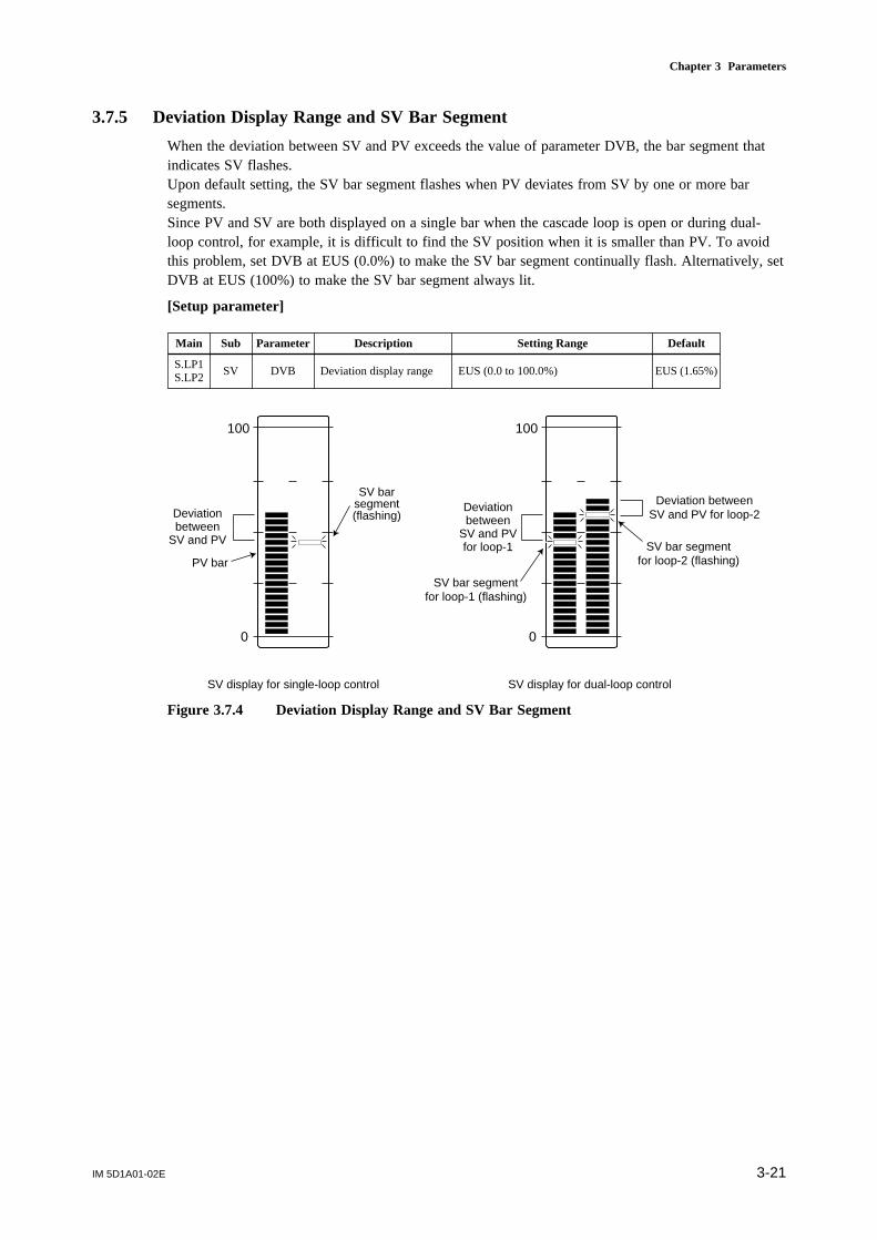
IM 5D1A01-02E 3-21
Chapter 3 Parameters
3.7.5 Deviation Display Range and SV Bar Segment
When the deviation between SV and PV exceeds the value of parameter DVB, the bar segment thatindicates SV flashes.Upon default setting, the SV bar segment flashes when PV deviates from SV by one or more barsegments.Since PV and SV are both displayed on a single bar when the cascade loop is open or during dual-loop control, for example, it is difficult to find the SV position when it is smaller than PV. To avoidthis problem, set DVB at EUS (0.0%) to make the SV bar segment continually flash. Alternatively, setDVB at EUS (100%) to make the SV bar segment always lit.
[Setup parameter]
Main Sub Parameter Description Setting Range Default
S.LP1S.LP2
SV DVB EUS (1.65%)Deviation display range EUS (0.0 to 100.0%)
100
0
Deviation betweenSV and PV for loop-2
Deviationbetween
SV and PVfor loop-1
100
0
Deviationbetween
SV and PV
SV display for single-loop control SV display for dual-loop control
SV bar segmentfor loop-2 (flashing)
SV bar segmentfor loop-1 (flashing)
SV barsegment(flashing)
PV bar
Figure 3.7.4 Deviation Display Range and SV Bar Segment
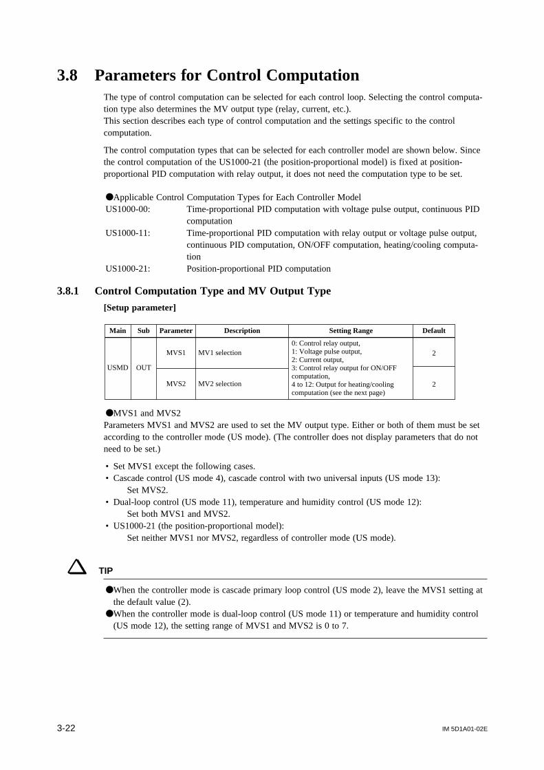
IM 5D1A01-02E3-22
3.8 Parameters for Control ComputationThe type of control computation can be selected for each control loop. Selecting the control computa-tion type also determines the MV output type (relay, current, etc.).This section describes each type of control computation and the settings specific to the controlcomputation.
The control computation types that can be selected for each controller model are shown below. Sincethe control computation of the US1000-21 (the position-proportional model) is fixed at position-proportional PID computation with relay output, it does not need the computation type to be set.
Applicable Control Computation Types for Each Controller ModelUS1000-00: Time-proportional PID computation with voltage pulse output, continuous PID
computationUS1000-11: Time-proportional PID computation with relay output or voltage pulse output,
continuous PID computation, ON/OFF computation, heating/cooling computa-tion
US1000-21: Position-proportional PID computation
3.8.1 Control Computation Type and MV Output Type
[Setup parameter]
Main Sub Parameter Description Setting Range Default
USMD OUT
0: Control relay output,1: Voltage pulse output,2: Current output,3: Control relay output for ON/OFF computation,4 to 12: Output for heating/cooling computation (see the next page)
MVS1 MV1 selection
MVS2 MV2 selection
2
2
MVS1 and MVS2Parameters MVS1 and MVS2 are used to set the MV output type. Either or both of them must be setaccording to the controller mode (US mode). (The controller does not display parameters that do notneed to be set.)
• Set MVS1 except the following cases.• Cascade control (US mode 4), cascade control with two universal inputs (US mode 13):
Set MVS2.• Dual-loop control (US mode 11), temperature and humidity control (US mode 12):
Set both MVS1 and MVS2.• US1000-21 (the position-proportional model):
Set neither MVS1 nor MVS2, regardless of controller mode (US mode).
TIP
When the controller mode is cascade primary loop control (US mode 2), leave the MVS1 setting atthe default value (2).
When the controller mode is dual-loop control (US mode 11) or temperature and humidity control(US mode 12), the setting range of MVS1 and MVS2 is 0 to 7.

IM 5D1A01-02E 3-23
Chapter 3 Parameters
The control computation types and MV output types are summarized in the following table.
Control Computation Type Setting of MVSn MV Output Type Description
Time-proportional PIDcomputation with relay output
PID computation result is output in the pulsewidth of a time-proportional on/off signal.
Control relayoutput
Continuous PID computation PID computation result is output as an analog signal. Current output
0
2
Position-proportional PIDcomputation
Control is performed so as to maintain the MVoutput in accordance with the control valve opening.
Position-proportionalcontrol relay output
None
Heating/cooling computationThe PID or ON/OFF computation*2 result isoutput as two types of signals for the heatingand cooling output.
Control relay*2,voltage pulse*2, orcurrent output canbe selected for eachof heating-side andcooling- side outputs
4 to 12*1
ON/OFF computationSV and PV are compared and an ON or OFFsignal is output according to the sign of thedeviation.
Control relayoutput
3
Time-proportional PIDcomputation with voltagepulse output
PID computation result is output in the pulsewidth of a time-proportional on/off signal.
Voltage pulseoutput
1
*1 The MV output types for the heating/cooling computation are as follows. Single-loop control or cascade control4: Heating control relay output / cooling control relay output5: Heating pulse output / cooling control relay output6: Heating current output / cooling control relay output7: Heating control relay output / cooling pulse output8: Heating pulse output / cooling pulse output9: Heating current output / cooling pulse output10: Heating control relay output / cooling current output11: Heating pulse output / cooling current output12: Heating current output / cooling current output Dual-loop control or temperature and humidity control
(Both of the loop-1 and loop-2 have the same output combinations.)4: Heating pulse output / cooling control relay output5: Heating control relay output / cooling pulse output6: Heating current output / cooling control relay output7: Heating control relay output / cooling current output*2 Setting the proportional band (n.P or n.Pc) at 0 enables ON/OFF signal resulting from ON/OFF
computation to be output.

IM 5D1A01-02E3-24
3.8.2 Time-proportional PID Computation and Cycle Time of MV Output
The cycle time of an MV output must be set for time-proportional PID computation.
[Setup parameter]
Main Sub Parameter Description Setting Range Default
CMLP C.CTLCT1 Cycle time of MV1 1 to 1000 s 30 s
CT2 Cycle time of MV2 1 to 1000 s 30 s
Main Sub Parameter Description Setting Range Default
CMLP C.CTLCT1 Cycle time of MV1 1 to 1000 s 30 s
CT2 Cycle time of MV2 1 to 1000 s 30 s
In time-proportional PID computation, the fundamental period of time at which the relay or voltagepulse output turns ON and OFF is called the “cycle time.” The type of output used – relay or voltagepulse – is set using parameter MVS1 or MVS2. The cycle time of MV output can be set in secondsusing parameter CT1 or CT2. The proportion of ON time within the cycle time is proportional to theMV output.
Cycle time
ON
OFF
ON
OFF
Cycle time
ON time
Figure 3.8.1 Cycle Time of MV Output
A short cycle time enables fine control, but may reduce the service life time of the controller’s outputrelay and the input contact of the final control element due to the fact that the number of ON/OFFswitchings is increased. Generally, the cycle time of MV output is set between 10 and 30 seconds forrelay contact output.The following figure compares the actions of different cycle times when MV output = 50%.
Cycle time = 20 s Cycle time = 40 s Cycle time = 10 s
ON
OFF
Figure 3.8.2 Comparing ON/OFF Actions of Different Cycle Times
3.8.3 Continuous PID Computation
With continuous PID computation, the result of the PID computation is output in a current signal(analog outp ut) in proportion to the result.
See Also Section 3.9, “Parameters for PID Computation,” for information on PID computation; and subsection3.12.1, “Analog Output Type,” for information about analog output types.

IM 5D1A01-02E 3-25
Chapter 3 Parameters
3.8.4 ON/OFF Computation and Hysteresis
The output type of ON/OFF computation is relay contact. A hysteresis band can be set around the ON/OFF switching point (SV).
[Operation parameter]
Main Sub Parameter Description Setting Range Default
0.LP10.LP2
n.PID (n=1-8)
n.H Hysteresis
ON/OFF computation: EUS (0.0 to 100.0%), Position proportional PID or heating/cooling computation: 0.0 to 100.0%
ON/OFF computation: EUS (0.5%), Position proportional PID or heating/cooling computation: 0.5%
NOTEWhen the relay is expected to be turned on and off frequently, set a somewhat wider hysteresis inconsideration of the fact that the service life of the output relay will be significantly reduced.
ON ONOFF OFF
SV
MV
Hysteresis band
PV
Figure 3.8.3 Hysteresis for ON/OFF Computation
3.8.5 Heating/Cooling Computation and Cycle Time, Hysteresis, and Deadband
In heating/cooling computation, the PID computation result is output as two signals for heating andcooling.
See Also Subsection 3.9.2, “Cooling-side PID Parameters for Heating/Cooling Computation,” for information onthe PID computation for heating/cooling computation.
[Setup parameter]
Main Sub Parameter Description Setting Range Default
CMLP C.CTLCTcl Cycle time of cooling side MV1 1 to 1000 s 30 s
CTc2 Cycle time of cooling side MV2 1 to 1000 s 30 s
When the cooling-side output is relay contact or voltage pulse (that is, parameter MVS1 or MVS2 hasbeen set between 4 and 9), the cycle time of the cooling-side MV output (CTc1 or CTc2) must be set.For a description of the cycle time, refer to subsection 3.8.2, “Time-proportional PID Computation andCycle Time of MV Output.”

IM 5D1A01-02E3-26
[Operation parameter]
Main Sub Parameter Description Setting Range Default
0.LP10.LP2
n.PID (n=1-8)
n.Hc Cooling-side relay hysteresis 0.0 to 100.0% 0.5%
When the cooling-side output is relay contact (that is, parameter MVS1 or MVS2 has been setbetween 4 and 6), a hysteresis band can be set around the ON/OFF switching point (SV). For adescription of the hysteresis, refer to subsection 3.8.4, “ON/OFF Computation and Hysteresis.”
[Operation parameter]
Main Sub Parameter Description Setting Range Default
0.LP10.LP2
n.PID (n=1-8) n.DB Deadband
Heating/cooling computation: -100.0 to 50.0%Position proportional PID computation: 1.0 to 10.0% 3.0%
A deadband (positive) is the area where no MV is output for the heating-side or cooling-side. Adeadband is set as a proportion of the output span (%). For a negative deadband, the MV outputoverlaps both the heating-side and cooling-side.
Heating-side relayhysteresis
20 mA(5 V)DC100 %
4 mA(1 V)DC
0% 0 50 100
Heating/cooling
MV output
Heating/cooling
MV output
Heating/cooling
MV output
Heating/cooling
MV output
Cooling Heating
Cooling Heating
Cooling Heating
Cooling Heating
Deadband(+)
Positive deadband
MV output (%) →
20 mA(5 V)DC100 %
4 mA(1 V)DC
0% 0 50 100
Deadband(-)
Negative deadband
MV output (%) →
20 mA(5 V)DC100 %
4 mA(1 V)DC
0% 0 50 100
Deadband
ON/OFF action on the heating side
MV output (%) →
Heating-side relayhysteresis
Cooling-side relayhysteresis
ON
OFF
0 50 100
ON/OFF action on both the heatingand cooling sides
MV output (%) →
Deadband
Figure 3.8.4 Deadbands

IM 5D1A01-02E 3-27
Chapter 3 Parameters
3.8.6 Position-proportional PID Computation and Valve Position
[Setup parameter]
Main Sub Parameter Description Setting Range Default
USMD VALV
V.RS Reset valve position 0, 1; Setting 1 clears valve position data. 0
V.L Valve in fully-closed position
The position data of a fully-closed valve is saved when the SET/ENT key is pressed after a valve is fully closed using the key.
Indefinite
V.H Valve in fully-opened position
The position data of a fully-opened valve is saved when the SET/ENT key is pressed after a valve is fully opened using the key.
Indefinite
V.ATAutomatic calibration for valve positioning
OFF, ON OFF
Position-proportional PID control is the control method that maintains the valve position to achieveMV by monitoring MV and the feedback input from the valve.The feedback input from the valve is sent by a feedback slide (slide rheostat) attached to the valvestem. The relay is controlled to make the valve position correspond to the MV using both the feedbackinput and control computation result (position-proportional PID control).
Motor-operated valve
Controlmotor
Slide rheostat
Pipe line
US1000
58
59
60
55
56
57
Valve positionfeedback input
Controlcomputation
MV(position-proportionalrelay-contact output)
Open
Close
Valvestem
Resistance
Resistance
Figure 3.8.5 Controlling the Motor-operated Valve by Position-proportional PID Control
See Also See section 4.9 “(17) Calibration of valve position (US1000-21 only)” of the separate ‘US1000 DigitalIndicating Controller’ manual, for the operations.

IM 5D1A01-02E3-28
3.9 Parameters for PID ComputationThis section describes PID computation and the parameters related to PID computation.
3.9.1 PID Parameters
When the controller uses the zone PID or preset PID function (see Section 3.10, “Parameters forPreset PID and Zone PID”), a maximum of 8 sets of PID parameters can be set. When the controllerdoes not use either of these, only 1.P, 1.I, and 1.D are used.For heating/cooling computation, parameters n.P, n.I, and n.D, which are described here, are used forthe heating-side PID parameters. For the cooling-side PID parameters, n.Pc, n.Ic, and n.Dc are used.These are described in subsection 3.9.2, “Cooling-side PID Parameters for Heating/Cooling Computa-tion.”Individual PID parameters are described here.
[Operation parameter]
Main Sub Parameter Description Setting Range Default
n.P Proportional band0.1 to 999.9%, 0.0 to 999.9% for heating/cooling computation
999.9%
n.I Integral time OFF, 1 to 6000 s 1000 s
n.D Derivative time OFF, 1 to 6000 s OFF
0.LP10.LP2
n.PID (n=1-8)
(1) Proportional Band (n.P)The control method in which the control output magnitude is proportional to the deviation is calledproportional action (P-action). The PV variation span (or deviation), which is expressed as a percent-age (%) and is required to change the control output (control computation output) from 0 to 100%, iscalled the “proportional band.” Generally, the output becomes 50% when PV matches SV. Theproportional action can remove the vibration from the output, the demerit of ON/OFF action.
PV
Time
SV
Small P (P = proportional action)
Medium P
Large P
The smaller P becomes, the more vibration in PV.
Figure 3.9.1 Proportional Action
TIP
Keep the following points in mind when performing fine adjustment on the proportional band obtainedfrom the auto-tuning function or when you tune the proportional band manually.• Change the proportional band from a larger to smaller value.• If cycling appears, it means the proportional band is too small.• An offset (steady-state deviation) cannot be removed by tuning the proportional band.

IM 5D1A01-02E 3-29
Chapter 3 Parameters
(2) Integral Time (n.I)The function that automatically reduces offsets, that cannot be avoided in principle, using the propor-tional action, is called an “integral action” (I-action). An integral action continually increases anddecreases the output in proportion to the integrated deviation (the product of the deviation span andthe deviation duration time). Integral action is generally used in combination with the proportionalaction. This is referred to as a proportional-plus-integral action (PI-action).Like a small proportional band, a short integral time results in a vibrational PV.The vibration derived from an integral action however, has a longer period than that derived from asmall proportional band.
PV
Time
SV
An integral time that is too short results in a long period of vibration in PV.
Figure 3.9.2 Integral Action
TIP
Keep the following points in mind when performing fine adjustment on the integral time obtainedfrom the auto-tuning function or when you tune the integral time manually.• The main purpose is to reduce the offset.• Change the integral time from a larger to smaller value.• If the vibration lasts longer than that observed when a small proportional band is used, it means theintegral time is too small.
(3) Derivative Time (n.D)In cases where the controlled process has a large time constant or a long dead time, control based ononly the proportional action or proportional-plus-integral action may require a late or excessivecorrective action. If attention is paid on whether the deviation is increasing or decreasing and acorrective action is taken earlier, the controllability will improve. Derivative action changes the outputin proportion to the differential value (rate of change) of deviation, and the derivative time parametersets the intensity of the derivative action.Setting the derivative time parameter n.D at OFF corresponds to derivative time = 0, during which thederivative action does not work. The n.D parameter must be set off for the control of inputs thatoriginally have vibrational characteristics — for example, inputs for prompt response such as pressureand flow rate, and inputs from optical sensors.
PV
Time
SV
A derivative time that is too long results in a short period of vibration in PV.
Figure 3.9.3 Derivative Action
IM 5D1A01-02E3-30
Bumpless TuningTo prevent a bump in MV when the parameter n.P is changed during manual tuning of the PIDparameters, the US1000 controller is provided with a function to absorb the effect of n.P changes byan integral action. This function allows for bumpless tuning and is always available regardless ofwhether there is any parameter setting.
Balance-less and Bumpless OperationTo prevent a bump in MV when the operation mode is changed from MAN to AUTO mode, theUS1000 controller is provided with a function that absorbs the effects of operation mode changesmade by the integral action. A balance-less and bumpless operation is allowed owing to this functionand is always available regardless of whether there is any parameter setting.
3.9.2 Cooling-side PID Parameters for Heating/Cooling Computation
[Operation parameter]
Main Sub Parameter Description Setting Range Default
0.LP1 n.PID (n=1-8)
n.Pc Cooling-side proportional band 0.0 to 999.9% 999.9%
n.Ic Cooling-side integral time OFF, 1 to 6000 s 1000 s
n.Dc Cooling-side derivative time OFF, 1 to 6000 s OFF
For heating/cooling computation, parameters n.P, n.I, and n.D, which are described in subsection 3.9.1,“PID Parameters,” are used for the heating-side PID parameters. The parameters n.Pc, n.Ic, and n.Dcare used for the cooling-side PID parameters.
See Also Subsection 3.9.1, “PID Parameters,” and note that the functions of n.Pc, n.Ic, and n.Dc are identical tothose of n.P, n.I, and n.D.
3.9.3 PID Control Mode
[Setup parameter]
Main Sub Parameter Description Setting Range Default
S.LP1S.LP2
CTL MOD PID control mode 0: Batch control; 1: Fixed point control 1
The US1000 controller has two modes of PID control: batch control mode and fixed-point controlmode. In these control modes, the controller uses different PID control equations for both the CAS andAUTO operation modes
Batch Control Mode (follow-up control)In CAS mode: Derivative-of-deviation PID control
(Good follow-up capability at SV change)In AUTO mode: PV-derivative PID control
(Follow-up capability at SV change and good stability) Fixed-point Control Mode
In CAS mode: PV-derivative PID control(Follow-up capability at SV change and good stability)
In AUTO mode: Proportional-plus-derivative PID control(Good stability because of small MV variation at SV change)

IM 5D1A01-02E 3-31
Chapter 3 Parameters
Block Diagram for Each PID Control EquationDerivative-of-deviation PID control
PIDSince derivation is performed on deviation,a better follow-up capability for the SV changeis obtained.
ProcessSVMV
PV
PV-derivative PID control (D-PI control)
PI
D
ProcessSVMV
PV
Since derivation is performed on PV, a smallervariation in the output resulting from the SVchange is obtained.This method is suitable in situations where SVis not changed very often.
Proportional-plus-derivative PID control (PD-I control)
Since only the integral action works at the SVchange, there is no sudden change in MV evenwhen SV is changed in steps from a personalcomputer or other device. This control methodproduces stable control, but its follow-up capabilityis not so good. This method is used for generalfixed-point control.
I
PD
ProcessSVMV
PV
3.9.4 Anti-reset Windup
[Setup parameter]
Main Sub Parameter Description Setting Range Default
S.LP1S.LP2
CTL AR Anti-reset windup AUTO; 50.0 to 200.0% AUTO
If a large deviation lasts for a long time, MV will reach its maximum level because the integral actionincreases MV to its high limit. If MV stays at this level even after PV reaches SV, an overshoot mayresult. To prevent this, the controller stops the PID computation and holds MV when it reaches itslimit. This function is called “anti-reset windup.”
PID computation is resumed when the deviation ratio obtained by the following expression has fallenbelow the value of the parameter AR.
Deviation ratio = | PV - SV |/Proportional band (n.P)100
When parameter AR is set at AUTO, the US1000 automatically determines the point at which toresume PID computation.
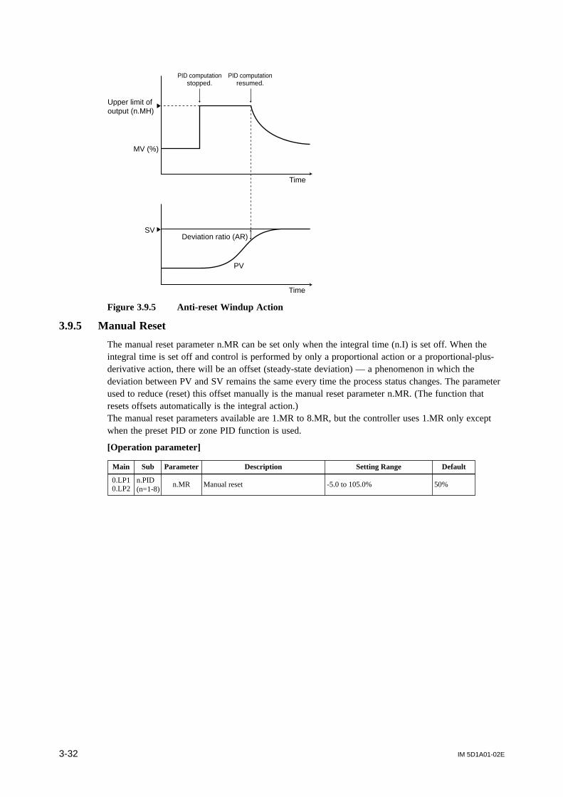
IM 5D1A01-02E3-32
Deviation ratio (AR)SV
MV (%)
PV
PID computationstopped.
PID computationresumed.
Time
Time
Upper limit ofoutput (n.MH)
Figure 3.9.5 Anti-reset Windup Action
3.9.5 Manual Reset
The manual reset parameter n.MR can be set only when the integral time (n.I) is set off. When theintegral time is set off and control is performed by only a proportional action or a proportional-plus-derivative action, there will be an offset (steady-state deviation) — a phenomenon in which thedeviation between PV and SV remains the same every time the process status changes. The parameterused to reduce (reset) this offset manually is the manual reset parameter n.MR. (The function thatresets offsets automatically is the integral action.)The manual reset parameters available are 1.MR to 8.MR, but the controller uses 1.MR only exceptwhen the preset PID or zone PID function is used.
[Operation parameter]
Main Sub Parameter Description Setting Range Default
n.MR0.LP10.LP2
n.PID (n=1-8)
Manual reset -5.0 to 105.0% 50%

IM 5D1A01-02E 3-33
Chapter 3 Parameters
3.9.6 Direct/Reverse Action of Control
Direct action: Control action that increases MV to achieve a positive deviation (PV > SV) andreduces MV to achieve a negative deviation (PV < SV)
Reverse action: Control action that reduces MV to achieve a positive deviation and increasesMV to achieve a negative deviation
Parameters to switch between the direct or reverse action are provided as 1.DR to 8.DR, but thecontroller uses only 1.DR except when the preset PID or zone PID function is used.
[Operation parameter]
Main Sub Parameter Description Setting Range Default
0.LP10.LP2
n.PID (n=1-8)
n.DR Direct/reverse action switchover0: Reverse action;1: Direct action
0
Negative deviation Positive deviation
MV(%)Direct action PV
Reverse action PV
SV
Proportionalband (n.P)
100
0
50
Figure 3.9.5 Direct Action and Reverse Action

IM 5D1A01-02E3-34
3.10 Parameters for Preset PID and Zone PIDThe US1000 controller can have multiple groups of preset PID parameters and switches between theseparameter groups according to the controlled process condition. This function is called a “preset PID”or “zone PID” depending on the switching method.Preset PID is a function in which the operator switches PID groups by setting the parameter SVNO(SV number selection).Zone PID is a function in which PID groups are switched automatically corresponding to the PVranges set by the zone PID reference point parameters n.RP.
TIP
A PID group denotes a set of parameters that belong to the operation parameter submenus 1.PID to8.PID. Each PID group has one target setpoint (SV), four alarm setpoints, and one of each PIDparameter and other parameters. A maximum of 8 sets of PID groups can be used per control loop,and each parameter is numbered from 1 to 8. These numbers are called either a “PID group number”or an “SV number.”
1.PID submenu 2.PID submenu 8.PID submenu
Parameter
Parameter
Parameter
Parameter
Parameter
Parameter
Parameter
Parameter
Parameter
Parameter
Parameter
Parameter
Parameter
Parameter
Parameter
Parameter
Parameter
Parameter
Parameter
Parameter
Parameter
PID group 1 PID group 2 PID group 8
3.10.1 Preset PID
Select either the preset PID or zone PID by setting the parameter PPID. To select neither of them foruse, set 0.
0: Selects neither the preset PID nor the zone PID for use. With this setting, the controller displaysonly one PID group (the parameters under 1.PID submenu) and performs control computationusing one set of PID parameters for any SV value.
1: Selects the preset PID for use. In this case, the PID group number is specified by setting parameterSVNO (SV number selection). Refer to subsection 3.10.2, “SV Number Selection for Preset PID.”
2: Selects the zone PID for use. In this case, set the zone PID reference point parameters n.RP priorto operation. Refer to subsection 3.10.3, “Zone PID.”
[Setup parameter]
Main Sub Parameter Description Setting Range Default
CMLP C.CTL PPID Preset PID function selection0: Disabled Preset PID1: SV number selection2: Zone PID
0
IM 5D1A01-02E 3-35
Chapter 3 Parameters
3.10.2 SV Number Selection for Preset PID
Parameter SVNO is used for switching PID group numbers (“SV number” hereafter) when the presetPID function is used. The SV number can also be switched by contact inputs. (Refer to Section 3.15,“Parameters for Contact Input.”) The switching by contact inputs takes priority over switching byparameter setting. The SV number can be switched any time during operation. When the SV number isswitched, SV changes at the preset SV rate-of-change. (Refer to subsection 3.7.4, “SV Rate-of-Change(Ramp Rate).”)
[Operation parameter]
Main Sub Parameter Description Setting Range Default
MODE — SVNO SV number selection 1 to 8 1
NOTETo specify a PID group number (SV number) with parameter SVNO, be sure to turn off all the contactinputs registered to parameters SV.B0 to SV.B3. (Refer to Section 3.15, “Parameters for ContactInput.”)
See Also Set USER display parameter U.SVN to ON for displaying the selected SV number during operations.See section 5.1 of the separate ‘US1000 Digital Indicating Controller’ manual for information aboutthe USER display.
3.10.3 Zone PID
To use the zone PID function, set the PV ranges for PID group switching using the zone PID refer-ence point parameters beforehand. Hysteresis at switching can also be set. It is also possible tocombine switching over PV ranges and switching according to deviation.
[Operation parameter]
Main Sub Parameter Description Setting Range Default
0.LP10.LP2
n.PID n=1-6
n.RP Zone PID reference pointEU (0.0 to 100.0%) provided that 1.RP≤2.RP≤3.RP≤ 4.RP≤5.RP≤6.RP
EU (100.0%)
7.PID RHY Zone PID hysteresis EUS (0.0 to 10.0%) EUS (0.5%)
8.PID RDV Zone PID reference deviation OFF, EUS (0.0 to 100.0%) OFF
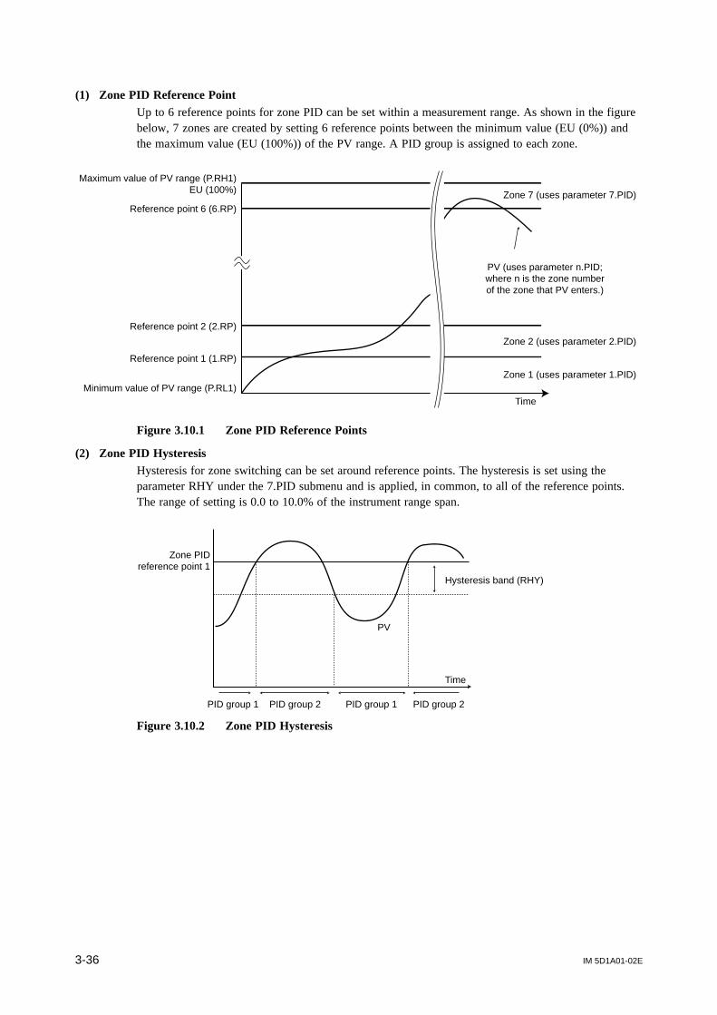
IM 5D1A01-02E3-36
(1) Zone PID Reference PointUp to 6 reference points for zone PID can be set within a measurement range. As shown in the figurebelow, 7 zones are created by setting 6 reference points between the minimum value (EU (0%)) andthe maximum value (EU (100%)) of the PV range. A PID group is assigned to each zone.
Maximum value of PV range (P.RH1)EU (100%)
Minimum value of PV range (P.RL1)
Reference point 1 (1.RP)
Reference point 2 (2.RP)
Reference point 6 (6.RP)
Time
Zone 2 (uses parameter 2.PID)
Zone 1 (uses parameter 1.PID)
Zone 7 (uses parameter 7.PID)
PV (uses parameter n.PID;where n is the zone numberof the zone that PV enters.)
Figure 3.10.1 Zone PID Reference Points
(2) Zone PID HysteresisHysteresis for zone switching can be set around reference points. The hysteresis is set using theparameter RHY under the 7.PID submenu and is applied, in common, to all of the reference points.The range of setting is 0.0 to 10.0% of the instrument range span.
Zone PIDreference point 1
Hysteresis band (RHY)
PID group 1 PID group 2 PID group 1 PID group 2
Time
PV
Figure 3.10.2 Zone PID Hysteresis

IM 5D1A01-02E 3-37
Chapter 3 Parameters
(3) Zone PID Reference DeviationIf the deviation (|PV - SV|) grows larger than the reference deviation during the zone PID operation,the controller stops using the PID group being used at that time (corresponding to the zone) andrestarts operation using the parameters under the 8.PID submenu.
For example, by setting the proportional band parameter of 8.PID to a small value (large proportionalgain), PV will be able to reach SV quickly because the PID group automatically switches to 8.PIDwhen deviation grows large.When the deviation is reduced to a smaller value than the reference deviation, the controller changesback to the operation with the PID group of the zone that corresponds to the current PV value.For example, assume that the controller’s measurement range is 0 to 1000°C. An RDV setting of 1%will make a reference deviation of 10°C.Assuming that SV is 500°C, which is in zone 2, the RDV upper limit will be 510°C and the RDVlower limit, 490°C. When PV goes out of this reference deviation range, the controller stops usingparameter 2.PID and starts using parameter 8.PID.
Zone PIDreference point 1
Zone PIDreference point 2
Time
SV (500°C)
Zone 2
Zone 3
Zone 1
PV
RDV upper limit (510°C)
RDV lower limit (490°C)
Reference deviation (10°C)
Reference deviation (10°C)
Uses parameter 8.PIDUses parameter 2.PID
Figure 3.10.3 Zone PID Reference Deviation
See Also Set USER display parameter U.1PI or U.2PI to ON for displaying the used PID group number duringoperations.See section 5.1 of the separate ‘US1000 Digital Indicating Controller’ manual for information aboutthe USER display.
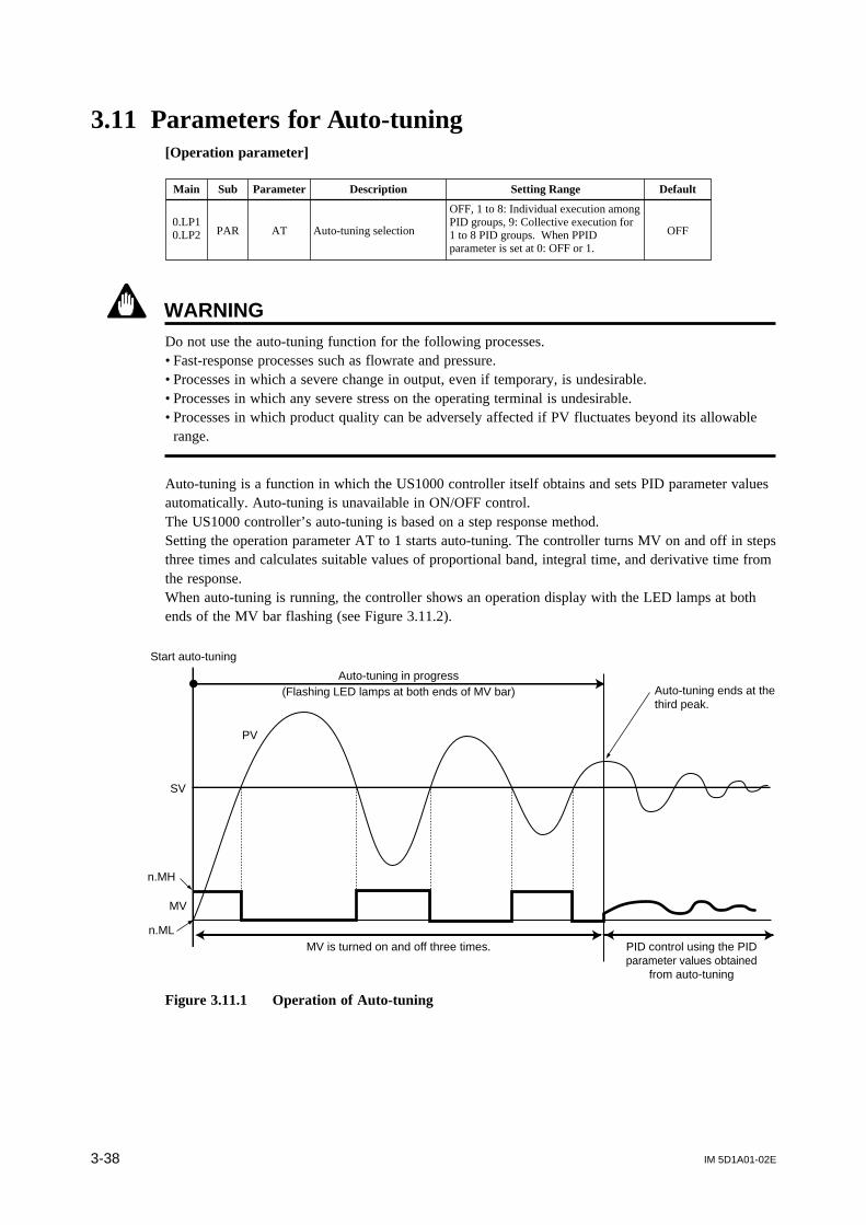
IM 5D1A01-02E3-38
3.11 Parameters for Auto-tuning[Operation parameter]
Main Sub Parameter Description Setting Range Default
AT Auto-tuning selection
OFF, 1 to 8: Individual execution among PID groups, 9: Collective execution for 1 to 8 PID groups. When PPID parameter is set at 0: OFF or 1.
OFF0.LP10.LP2 PAR
WARNINGDo not use the auto-tuning function for the following processes.• Fast-response processes such as flowrate and pressure.• Processes in which a severe change in output, even if temporary, is undesirable.• Processes in which any severe stress on the operating terminal is undesirable.• Processes in which product quality can be adversely affected if PV fluctuates beyond its allowable
range.
Auto-tuning is a function in which the US1000 controller itself obtains and sets PID parameter valuesautomatically. Auto-tuning is unavailable in ON/OFF control.The US1000 controller’s auto-tuning is based on a step response method.Setting the operation parameter AT to 1 starts auto-tuning. The controller turns MV on and off in stepsthree times and calculates suitable values of proportional band, integral time, and derivative time fromthe response.When auto-tuning is running, the controller shows an operation display with the LED lamps at bothends of the MV bar flashing (see Figure 3.11.2).
Start auto-tuning
Auto-tuning ends at thethird peak.
Auto-tuning in progress(Flashing LED lamps at both ends of MV bar)
MV is turned on and off three times. PID control using the PIDparameter values obtained
from auto-tuning
SV
PV
n.MH
n.ML
MV
Figure 3.11.1 Operation of Auto-tuning

IM 5D1A01-02E 3-39
Chapter 3 Parameters
C O
Flashing LED lamps at both ends of MV bar graph
Figure 3.11.2 Display during Auto-tuning
The step MV variation of auto-tuning is regulated within the upper and lower limits of output (opera-tion parameters n.MH and n.ML). The SV change made during auto-tuning will be ignored and the SVat the start of auto-tuning is maintained. The SV rate-of-change function (operation parameters UPRand DNR) does not work while auto-tuning is running.
Auto-tuning Operations under Preset PID and Zone PIDOperation of auto-tuning differs as described below depending on the setting of setup parameter PPID.(Refer to Section 3.10, “Parameters for Preset PID and Zone PID.”)
(1) When only one set of PID parameters is used (PPID = 0)• Auto-tuning can be executed only for PID group 1.• The setting of parameter AT is either OFF or 1.• The SV at the start of auto-tuning is used for auto-tuning.• The PID values obtained from auto-tuning will be stored to 1.P, 1.I, and 1.D.
(2) When preset PID is being executed (PPID = 1)• Auto-tuning is executed for the PID group of the number specified to parameter AT, regardless of
the PID group number set with parameter SVNO.• The SVs set for each PID group with parameter n.SV are used for auto-tuning.• The PID values obtained from auto-tuning will be stored to the PID parameters of the PID group
number specified to parameter AT. (For example, when AT is set at 3, the values of 3.P, 3.I, and3.D will be obtained.)
• When parameter AT is set at 9, auto-tuning is executed for PID groups 1 to 8 in succession, and thePID values obtained are stored to the PID parameters of the respective groups.
(3) When zone PID is being executed (PPID = 2)
WARNINGThere is a possibility that the controlled process will be damaged when PV reaches the limit of theprocess. To prevent this, set the reference points and the maximum value of the PV range (P.RHn) sothat the PV does not exceed the limit of the controlled process, before starting auto-tuning with AT setat 9 under zone PID.

IM 5D1A01-02E3-40
• Regardless of the current zone number, auto-tuning is executed for the PID group of the numberspecified to the AT parameter.
• The SV at the start of auto-tuning is used for auto-tuning. However, when parameter AT is set at 9,the SV used for auto-tuning will be as shown in Figure 3.11.3. For PID groups 1 to 7, auto-tuningis performed taking the intermediate value of each zone for SV. For PID group 8, auto-tuning isperformed taking the intermediate value of the maximum and minimum values of the PV range forSV.
• The PID values obtained through auto-tuning will be stored to the PID parameters of the PID groupnumber specified to parameter AT. (For example, when AT has been set at 3, the values of 3.P, 3.I,and 3.D will be obtained.) When parameter AT is set at 9, the obtained PID values will be stored tothe PID parameters of PID groups 1 to 8.
• When the controller is set up for heating/cooling computation, auto-tuning will not be performed forthe zone where on/off control is specified (when the proportional band n.P or n.Pc is set at 0) buttransfer to the next zone.
Maximum value of PV range
Minimum value of PV range
Intermediate valueof reference points
For PID group 8, theintermediate value ofthe PV range is usedfor SV.
Reference point 1 (1.RP)
Reference point 2 (2.RP)
Reference point 6 (6.RP)
PV
Time
Zone 7
Zone 2
Zone 1
PID group 2
PID group 1
PID group 7
Figure 3.11.3 Auto-tuning When Setting AT to 9 under Zone PID
TIP
At the time of shipping, the reference points are set at the same value as the maximum value of thePV range (EU (100%)). To execute auto-tuning under zone PID, change the reference point settingsto proper values.
In either of the following cases, set the maximum and minimum values of the PV range so that theintermediate value of each zone will be appropriate for auto-tuning — for example, set the mini-mum value of the PV range to room temperature.
• Reference point 1 and the minimum value of the PV range differ greatly.• The uppermost reference point and the maximum value of the PV range differ greatly.
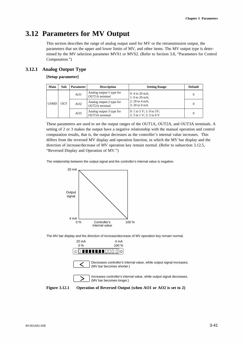
IM 5D1A01-02E 3-41
Chapter 3 Parameters
3.12 Parameters for MV OutputThis section describes the range of analog output used for MV or the retransmission output, theparameters that set the upper and lower limits of MV, and other items. The MV output type is deter-mined by the MV selection parameter MVS1 or MVS2. (Refer to Section 3.8, “Parameters for ControlComputation.”)
3.12.1 Analog Output Type
[Setup parameter]
Main Sub Parameter Description Setting Range Default
USMD OUT
AO1Analog output-1 type for OUT1A terminal
AO2Analog output-2 type for OUT2A terminal
AO3Analog output-3 type for OUT3A terminal
0: 4 to 20 mA;1: 0 to 20 mA;2: 20 to 4 mA;3: 20 to 0 mA
0: 1 to 5 V; 1: 0 to 5V; 2: 5 to 1 V; 3: 5 to 0 V
0
0
0
These parameters are used to set the output ranges of the OUT1A, OUT2A, and OUT3A terminals. Asetting of 2 or 3 makes the output have a negative relationship with the manual operation and controlcomputation results, that is, the output decreases as the controller’s internal value increases. Thisdiffers from the reversed MV display and operation function, in which the MV bar display and thedirection of increase/decrease of MV operation key remain normal. (Refer to subsection 3.12.5,“Reversed Display and Operation of MV.”)
0 % 100 %Controller'sinternal value
Outputsignal
20 mA
4 mA
Decreases controller's internal value, while output signal increases.(MV bar becomes shorter.)
Increases controller's internal value, while output signal decreases.(MV bar becomes longer.)
C O
0 % 100 %20 mA 4 mA
The MV bar display and the direction of increase/decrease of MV operation key remain normal.
The relationship between the output signal and the controller's internal value is negative.
Figure 3.12.1 Operation of Reversed Output (when AO1 or AO2 is set to 2)

IM 5D1A01-02E3-42
3.12.2 Output Limiter
[Operation parameter]
Main Sub Parameter Description Setting Range Default
n.MHUpper limit of output
n.ML +0.1% to 105.0%;0.0 to 105.0% for heating-side output limit in heating/cooling computation
100.0%
n.MLLower limit of output
-5.0 % to n.MH - 0.1%;0.0 to 105.0% for cooling-side output limit in heating/cooling computation
0.0%;heating/cooling computation: 100.0%
0.LP10.LP2
n.PID (n=1-8)
Upper and lower limits of MV can be set when operation mode is AUTO or CAS. Although param-eters for output limiter are provided as 1.MH to 8.MH and 1.ML to 8.ML, use only 1.MH and 1.MLexcept when preset PID or zone PID is to be used.
NOTEWhen the controller is set up for heating/cooling computation, the functions of n.MH and n.ML are asfollows:n.MH: Upper limit of heating-side outputn.ML: Upper limit of cooling-side output
(%)
(%)
105.0
105.0-5.0
-5.0
Output fromthe terminal
n.MH
n.ML
Range of internal MV
Figure 3.12.3 Output Limiter
Shutdown FunctionThis function fully closes a control valve beyond its positioner deadband. This function is availablewhen the output type is current of 4 to 20 mA and the operation mode is MAN.
When output is reduced using the key until “SHUT” appears on the SV digital display, theshutdown function starts to operate and the output falls to approx. 0.0 mA.

IM 5D1A01-02E 3-43
Chapter 3 Parameters
3.12.3 Output Rate-of-change Limiter
The output rate-of-change limiter prevents a sudden change in MV.While the output rate-of-change limiter is active, the derivative action is canceled. It is thus necessaryto use this limiter considering the effect of the cancellation when the control involves a derivativeaction.
[Setup parameter]
Main Sub Parameter Description Setting Range Default
S.LP1S.LP2 CTL MVR Output velocity limiter OFF, 0.1 to 100.0%/s OFF
The following figure illustrates the change in MV when the output rate-of-change limiter is set at 2%/second. Output changes linearly at a rate of 2% per second.
105.0
-5.0Time
MV (%)
80.0
20.0Output rate-of-change = 2.0%/second
30 seconds
Figure 3.12.3 Output Rate-of-change Limiter
3.12.4 Preset MV
In the following situations, the controller outputs the preset MV value as MV.
• The contact input for the RUN/STOP switchover has switched to the STOP status and the operationmode is AUTO or CAS.
• An input burnout or an abnormality in an analog/digital conversion circuit has occurred during theAUTO mode or CAS mode operation.
• The controller has been powered on or recovered from a power failure when parameter R.MD is setat COLD. (Refer to Section 3.1, “Parameters that Determine the Action at Power-on and PowerRecovery.”)
[Operation parameter]
Main Sub Parameter Description Setting Range Default
0.LP10.LP1
n.PID (n=1-8)
n.PM Preset MV -5.0 to 105.0% -5.0%
n.PMc Cooling-side preset MV -5.0 to 105.0% 0.0%
NOTEA preset output value is free from the limitations of the upper and lower limits of output. (Refer tosubsection 3.12.2, “Output Limiter.”)

IM 5D1A01-02E3-44
3.12.5 Reversed Display and Operation of MV
This function is used to open/close a valve with a reverse key operation. Setting the parameter RVOPto ON reverses the MV bar’s direction of increment when manually operated. As shown in Figure3.12.4, the right end of the MV bar becomes the 0% position, and the left end, the 100% position. The
key (normally the MV decrease key) adopts the function of increasing MV, and the key
(normally the MV increase key) adopts the function of decreasing MV. The OC marks at the ends ofthe MV bar can be reversed using the spare OC mark labels supplied as necessary with the controller.As shown in Figure 3.12.5, when the parameter AOn (analog output type) is set at 2 or 3, the bardisplay and the direction of manual operation remain normal, and the correspondence between thecontroller’s internal value and the output signal is reversed. On the other hand, when RVOP is set atON, the bar display and the direction of manual operation are reversed, and the correspondencebetween controller’s internal value and the output signal remains normal.
[Setup parameter]
Main Sub Parameter Description Setting Range Default
USMD OUT RVOP Reverse display and operation of MV OFF, ON OFF
Increases output. (MV bar increments toward the left)
OC mark labels
Decreases output. (MV bar decrements toward the right)
CO
100 % 0 %
Figure 3.12.4 Display in Reversed Display and Operation of MV
Reversed display and operationof MV (RVOP = ON) Negative output (AOn = 2)
0 % 100 % 0 % 100 %
Controller's internal value inmanual operation
Controller's internal value inmanual operation
Outputsignal
20mA
4mA
20mA
4mA
Figure 3.12.5 Difference between Reversed Display and Operation of MV and ReversedOutput

IM 5D1A01-02E 3-45
Chapter 3 Parameters
3.13 Parameters for Retransmission OutputThe retransmission output function is a function which outputs the controller’s PV, SV, or MV in ananalog signal (standard signal) to a device such as a recorder. The output range of the analog signal isset using parameter AOn. (Refer to subsection 3.12.1.)
3.13.1 Type of Retransmission Output
[Setup parameter]
Main Sub Parameter Description Setting Range Default
CMLP RET
RET1 Retransmission output-1 typeOFF: Disabled; 1: PV1; 2: SV1; 3: MV1; 4: PV2; 5: SV2; 6: MV2
3
RET2 Retransmission output-2 typeOFF: Disabled; 1: PV1; 2: SV1; 3: MV1; 4: PV2; 5: SV2; 6: MV2
2
RET3 Retransmission output-3 typeOFF: Disabled; 1: PV1, 2: SV1, 3: MV1, 4: PV2, 5: SV2, 6: MV2
1
The terminal which can be used for retransmission output differs depending on the controller’s modeland suffix code and the type of control computation in use. Refer to the block diagrams in chapter 2and confirm the code and number of the terminal that can be used for retransmission output. Then setthe following parameters.
• To use the OUT1A terminal for the retransmission output: RET1, RTH1, RTL1• To use the OUT2A terminal for the retransmission output: RET2, RTH2, RTL2• To use the OUT3A terminal for the retransmission output: RET3, RTH3, RTL3
3.13.2 Scale of Retransmission Output
[Setup parameter]
Main Sub Parameter Description Setting Range Default
CMLP RET
RTH1Maximum value of retransmission output-1 scale
RET1 = 1/2/4/5: RTL1 + 1 digit to EU (100.0%) *1
RET1 = 3/6: RTL1 + 1 digit to 100.0%*1 100.0
RTL1Minimum value of retransmission output-1 scale
RET1 = 1/2/4/5: EU (0.0%) to RTH1 - 1 digit *1
RET1 = 3/6: 0.0% to RTH1 - 1 digit *1
0.0
RTH2Maximum value of retransmission output-2 scale
RET2 = 1/2/4/5: RTL2 + 1 digit to EU (100.0%) *1
RET2 = 3/6: RTL2 + 1 digit to 100.0% *1
P.RH1
RTL2Minimum value of retransmission output-2 scale
RET2 = 1/2/4/5: EU (0.0%) to RTH2 - 1 digit *1
RET2 = 3/6: 0.0% to RTH2 - 1 digit *1
P.RL1
RTH3Maximum value of retransmission output-3 scale
RET3 = 1/2/4/5: RTL3 + 1 digit to EU (100.0%) *1
RET3 = 3/6: RTL3 + 1 digit to 100.0% *1
P.RH1
RTL3Minimum value of retransmission output-3 scale
RET3 = 1/2/4/5: EU (0.0%) to RTH3 - 1 digit *1
RET3 = 3/6: 0.0% to RTH3 - 1 digit *1
P.RL1
*1 “+ 1 digit” means to add 1 digit to the least significant value of the engineering unit.“- 1 digit” means to subtract 1 digit from the least significant value of the engineering unit.
For example, when RTL1 = 15°C, RTL1 + 1 digit makes 15.1°C.
The terminal which can be used for the retransmission output differs depending on the controllermodel and suffix code and the type of control computation in use. Set the necessary parameters byreferring to subsection 3.13.1, “Type of Retransmission Output.” Defaults are the maximum andminimum values of the PV range. (Refer to subsection 3.2.2, “Analog Input Range and PV Range.”)

IM 5D1A01-02E3-46
3.14 Parameters for Alarm OutputAlarm outputs have been already assigned to the contact outputs as factory-set defaults. (Refer toChapter 2.) Normally, these assignments need not be changed.The assigned alarm outputs can be set up in the following 3 steps.
(1) Set alarm type, hysteresis, and other parameters for each of alarm outputs 1 to 4.Refer to subsection 3.14.1, “Alarm Types.”The factory-set defaults of alarm types are the following.
• Alarm type of alarm output 1: PV high limit• Alarm type of alarm output 2: PV low limit• Alarm type of alarm output 3: PV high limit
(This alarm can be used as a high-high limit, or a secondary high-limit alarm.)• Alarm type of alarm output 4: PV low limit
(This alarm can be used as a low-low limit, or a secondary low-limit alarm.)
(2) Set an alarm setpoint for each of alarm outputs 1 to 4.Refer to subsection 3.14.2, “Alarm Setpoint.”
When an alarm occurs, the ALM lamp on the front panel lights up. To display the occurring alarmoutput numbers on the digital display on the front panel, make the following setting in step (3).
(3) Register the “loop-1 alarm” or “loop-2 alarm” to a USER display.Refer to subsection 3.18.1, “USER Display” or Section 5.1, “Registering Auxiliary Operation Displays(USER Displays)” of the separate instruction manual “US1000 Digital Indicating Controller” (IM5D1A01-01E).
3.14.1 Alarm Types
[Setup parameter]
Main Sub Parameter Description Setting Range Default
S.LP1S.LP2 ALM
AL1 Alarm 1 type OFF, 1 to 29 (see section 4.7) 1
AL2 Alarm 2 type OFF, 1 to 29 (see section 4.7) 2
AL3 Alarm 3 type OFF, 1 to 29 (see section 4.7) 1
AL4 Alarm 4 type OFF, 1 to 29 (see section 4.7)
EUS (0.0 to 100.0%),MV alarm: 0.0 to 100.0%
2
EUS (0.5%), MV alarm: 0.5%
HY1 Alarm 1 hysteresis
HY2 Alarm 2 hysteresis
HY3 Alarm 3 hysteresis
HY4 Alarm 4 hysteresis
PVR.TPV velocity alarm duration time
1 to 9999 s 1 s
AMD Alarm mode*1
0: Always enabled1: Disabled in STOP mode2: Disabled in STOP or MAN mode3: 8 alarms & always enabled4: 8 alarms & disabled in STOP mode5: 8 alarms & disabled in STOP or MAN mode
0
*1 The alarm mode parameter AMD under the S.LP2 main menu can only be set as 0, 1, or 2; it cannot be set to 3, 4, or 5.
Set the alarm type, hysteresis, and other parameters for each of alarm outputs 1 to 4.

IM 5D1A01-02E 3-47
Chapter 3 Parameters
The various alarm types are listed below.
Alarm type Setting Alarm type Setting
PV high limit 1 PV high limit with waiting action 11
PV low limit 2 PV low limit with waiting action 12
High limit deviation 3 High limit deviation with waiting action 13
Low limit deviation 4 Low limit deviation with waiting action 14
Deviation of high limit passive 5 Deviation of high limit passive with waiting action 15
Deviation of low limit passive 6 Deviation of low limit passive with waiting action 16
Deviation of high and low limits 7 Deviation of high and low limits with waiting action 17
Deviation within high and low limits 8 Deviation within high and low limits with waiting action 18
PV high limit passive 9 PV high limit passive with waiting action 19
PV low limit passive 10 PV low limit passive with waiting action 20
Alarm type Setting
SV high limit 21
SV low limit 22
MV high limit 23
MV low limit 24
PV velocity alarm 25
PV velocity alarm passive 26
Self-diagnostic alarm 27
Self-diagnostic alarm passive 28
FAIL passive 29
“Passive” AlarmsPassive alarms turn the contact OFF when the alarm occurs, and ON when normal.Other alarms (active alarms) turn the contact ON when the alarm occurs, and OFF when normal.
Alarms “With Waiting Action”Alarms numbered 11 to 20 are alarms “with a waiting action.” These alarms do not issue alarmsafter the following events until the normal state is achieved.
• The power is turned on, the power is recovered from the power failure, SV is changed, the SVnumber is switched, or the alarm type is changed.The following figure shows the operation of an alarm with the waiting action.
Time
Treated asnormal. Normal
Abnormal(Alarm output ON)
PV low limitalarm setpoint
In this area, the controller doesnot issue alarms even when PVfalls below the alarm setpoint.
Power-on
PV
Figure 3.14.1 Alarm with Waiting Action

IM 5D1A01-02E3-48
(1) PV high limit alarm (Setting: 1, 9, 11, 19)This alarm is issued when PV rises to the alarm setpoint or above. The alarms numbered 9 and 19 arepassive, and those numbered 11 and 19 have the waiting action.
Alarm setpoint Hysteresis
• The direction of the arrow indicates the direction of the PV change.• The alarm is issued within the range of the arrows.
(2) PV low limit alarm (Setting: 2, 10, 12, 20)This alarm is issued when PV falls to the alarm setpoint or below. The alarms numbered 10 and 20 arepassive, and those numbered 12 and 20 have the waiting action.
Alarm setpointHysteresis
• The direction of the arrow indicates the direction of the PV change.• The alarm is issued within the range of the arrows.
(3) High limit deviation alarm (Setting: 3, 5, 13, 15)This alarm is issued when the deviation (PV - SV) increases to the alarm setpoint or more. The alarmsnumbered 5 and 15 are passive, and those numbered 13 and 15 have the waiting action.(Figure 3.14.2)
(4) Low limit deviation alarm (Setting: 4, 6, 14, 16)This alarm is issued when the deviation (SV - PV) increases to the alarm setpoint or more. The alarmsnumbered 6 and 16 are passive, and those numbered 14 and 16 have the waiting action.(Figure 3.14.2)
(5) Deviation of high and low limits alarm (Setting: 7, 17)This alarm is issued when the deviation (SV - PV or PV - SV) increases to the alarm setpoint or more.The alarm numbered 17 has the waiting action.(Figure 3.14.2)
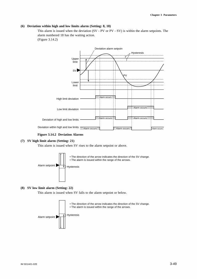
IM 5D1A01-02E 3-49
Chapter 3 Parameters
(6) Deviation within high and low limits alarm (Setting: 8, 18)This alarm is issued when the deviation (SV - PV or PV - SV) is within the alarm setpoints. Thealarm numbered 18 has the waiting action.(Figure 3.14.2)
Upperlimit
SV
Lowerlimit
Deviation alarm setpoin
Hysteresis
Alarm occurs
Alarm occurs
Alarm occursAlarm occurs
Alarm occurs Alarm occurs Alarm occurs
High limit deviation
Low limit deviation
Deviation of high and low limits
Deviation within high and low limits
PV
Figure 3.14.2 Deviation Alarms
(7) SV high limit alarm (Setting: 21)This alarm is issued when SV rises to the alarm setpoint or above.
Alarm setpoint Hysteresis
• The direction of the arrow indicates the direction of the SV change.• The alarm is issued within the range of the arrows.
(8) SV low limit alarm (Setting: 22)This alarm is issued when SV falls to the alarm setpoint or below.
Alarm setpointHysteresis
• The direction of the arrow indicates the direction of the SV change.• The alarm is issued within the range of the arrows.

IM 5D1A01-02E3-50
(9) MV high limit alarm (Setting: 23)This alarm is issued when MV rises to the alarm setpoint or above.
Alarm setpoint
Hysteresis
• The direction of the arrow indicates the direction of the MV change.• The alarm is issued within the range of the arrows.
0 % 100 %
(10) MV low limit alarm (Setting: 24)This alarm is issued when MV falls to the alarm setpoint or below.
Alarm setpoint
Hysteresis
• The direction of the arrow indicates the direction of the MV change.• The alarm is issued within the range of the arrows.
0 % 100 %
(11) PV velocity alarm (Setting: 25, 26)This alarm is issued when PV changes more than the alarm setpoint value within the period of timespecified in the parameter PVR.T. Hysteresis does not function. The alarm numbered 26 is passive.
10 s
50 °C
100 °C
20 s 30 sTime
The PV rate-of-changealarm occurs in this area
When PVR.T = 10 seconds,and the alarm setpoint is setat 20 °C.
PV
(12) Self-diagnostic alarm (Setting: 27, 28)This alarm is issued upon the following events:calibration value abnormal, reference junction compensation failure, analog/digital conversion circuitfailure, EEPROM failure, and input burnout.The alarm numbered 28 is passive.

IM 5D1A01-02E 3-51
Chapter 3 Parameters
(13) FAIL output (Setting: 29)The FAIL output is passive and turns the contact ON in normal state, and OFF when FAIL conditionsarise.The FAIL conditions include RAM failure, ROM failure, system data abnormal, CPU failure, andpower off.
TIP
The US1000 controller stops operation upon the FAIL conditions.(There is no MV output, and alarm outputs are turned off.)
See Also Subsection 8.5.2, “Error Code Description” of the separate instruction manual “US1000 DigitalIndicating Controller” (IM 5D1A01-01E) for information about displays and what to do upon a self-diagnostic alarm or FAIL output
The 8-alarm ModeThe 8-alarm mode is the function that uses loop-2 alarm outputs 1 to 4 for loop-1 alarm outputs 5 to8. This mode is unavailable with the controller mode (US mode) for cascade control, dual-loopcontrol, temperature and humidity control, or cascade control with two universal inputs.To use the 8-alarm mode, specify 3, 4, or 5 to the parameter AMD. The alarm outputs 5 to 8 for loop-1 can then be set up by setting the alarm type, alarm setpoint, and other alarm-related parameters forloop-2.Alarm outputs 5 to 8 can be accessed by setting them as contact outputs or reading them via commu-nication from an external device.The alarm setpoint of loop-2 and the display scale of analog input-2 are interlocking.Specify the same value to the display scale of analog input-1 and 2.
See Also Section 3.16, “Parameters for Contact Output” of this manual, or the separate instruction manual“US1000 Digital Indicating Controller Communication Functions” (IM 5D1A01-10E)
3.14.2 Alarm Setpoint
Set an alarm setpoint for each of alarm outputs 1 to 4.When the 8-alarm mode is specified, loop-2 alarm setpoints 1 to 4 are used for loop-1 alarm setpoints5 to 8.
[Operation parameter]
Main Sub Parameter Description Setting Range Default
n.A1 Alarm 1 setpoint PV alarm: EU (-100.0 to 100.0%)Deviation alarm/PV-velocity alarm: EUS(-100.0 to 100.0%) SV alarm: EU (0.0 to 100.0%)MV alarm: -5.0 to 105.0%
PV high limit: EU (100.0%) Deviation alarm: EUS (0.0%) MV high limit: 100.0% MV low limit: 0.0%PV velocity: EUS (100.0%) Other alarms: EU (0.0%)
n.A2 Alarm 2 setpoint
n.A3 Alarm 3 setpoint
n.A4 Alarm 4 setpoint
0.LP10.LP2
n.PID (n=1-8)
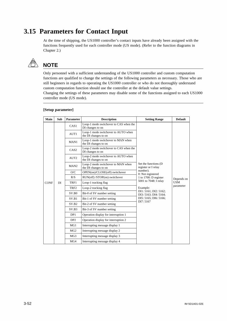
IM 5D1A01-02E3-52
3.15 Parameters for Contact InputAt the time of shipping, the US1000 controller’s contact inputs have already been assigned with thefunctions frequently used for each controller mode (US mode). (Refer to the function diagrams inChapter 2.)
NOTEOnly personnel with a sufficient understanding of the US1000 controller and custom computationfunctions are qualified to change the settings of the following parameters as necessary. Those who arestill beginners in regards to operating the US1000 controller or who do not thoroughly understandcustom computation function should use the controller at the default value settings.Changing the settings of these parameters may disable some of the functions assigned to each US1000controller mode (US mode).
[Setup parameter]
Main Sub Parameter Description Setting Range Default
CONF DI
CAS1Loop-1 mode switchover to CAS when the DI changes to on
AUT1Loop-1 mode switchover to AUTO when the DI changes to on
MAN1Loop-1 mode switchover to MAN when the DI changes to on
CAS2Loop-2 mode switchover to CAS when the DI changes to on
AUT2Loop-2 mode switchover to AUTO when the DI changes to on
MAN2Loop-2 mode switchover to MAN when the DI changes to on
O/C OPEN(on)/CLOSE(off) switchover
R/S RUN(off) /STOP(on) switchover
TRF1 Loop-1 tracking flag
TRF2 Loop-2 tracking flag
SV.B0 Bit-0 of SV number setting
SV.B1 Bit-1 of SV number setting
SV.B2 Bit-2 of SV number setting
SV.B3 Bit-3 of SV number setting
DP1 Operation display for interruption 1
DP2 Operation display for interruption 2
MG1 Interrupting message display 1
MG2 Interrupting message display 2
MG3 Interrupting message display 3
MG4 Interrupting message display 4
Set the functions (D register or I relay number).0: Not registered1 to 1700: D register5001 to 7048: I relay
Example:DI1: 5161; DI2: 5162; DI3: 5163; DI4: 5164; DI5: 5165; DI6: 5166; DI7: 5167
Depends on USM parameter
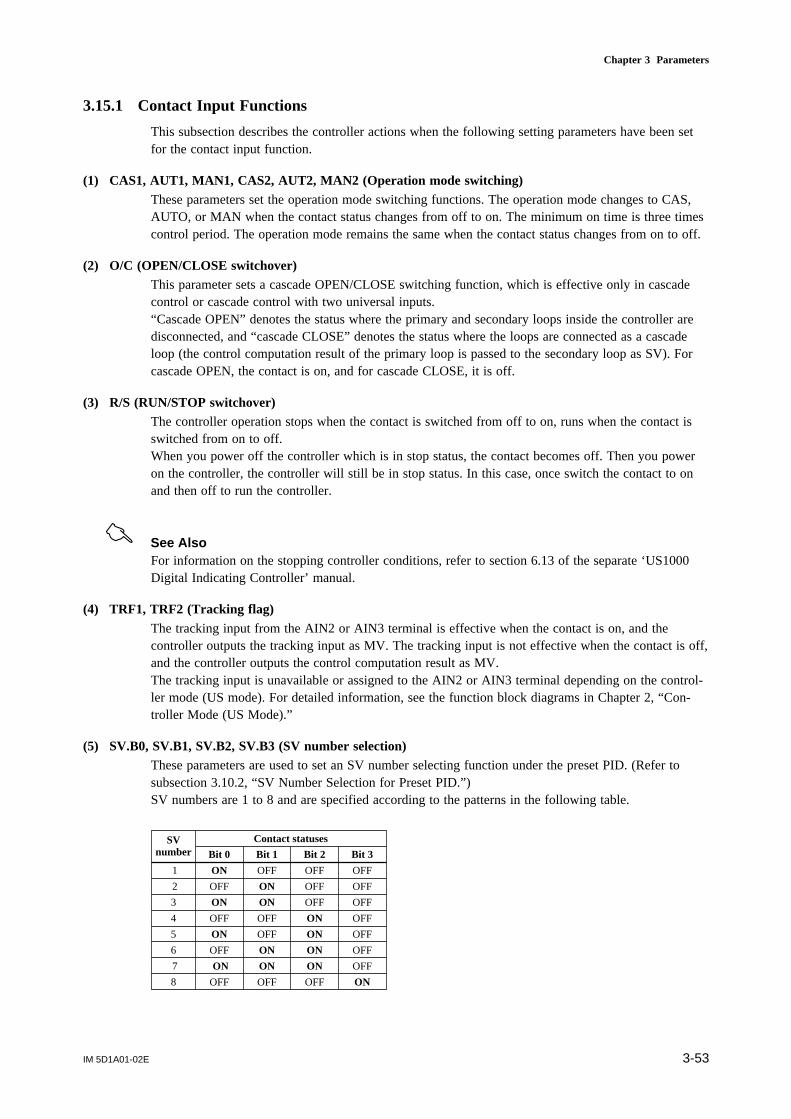
IM 5D1A01-02E 3-53
Chapter 3 Parameters
3.15.1 Contact Input Functions
This subsection describes the controller actions when the following setting parameters have been setfor the contact input function.
(1) CAS1, AUT1, MAN1, CAS2, AUT2, MAN2 (Operation mode switching)These parameters set the operation mode switching functions. The operation mode changes to CAS,AUTO, or MAN when the contact status changes from off to on. The minimum on time is three timescontrol period. The operation mode remains the same when the contact status changes from on to off.
(2) O/C (OPEN/CLOSE switchover)This parameter sets a cascade OPEN/CLOSE switching function, which is effective only in cascadecontrol or cascade control with two universal inputs.“Cascade OPEN” denotes the status where the primary and secondary loops inside the controller aredisconnected, and “cascade CLOSE” denotes the status where the loops are connected as a cascadeloop (the control computation result of the primary loop is passed to the secondary loop as SV). Forcascade OPEN, the contact is on, and for cascade CLOSE, it is off.
(3) R/S (RUN/STOP switchover)The controller operation stops when the contact is switched from off to on, runs when the contact isswitched from on to off.When you power off the controller which is in stop status, the contact becomes off. Then you poweron the controller, the controller will still be in stop status. In this case, once switch the contact to onand then off to run the controller.
See Also For information on the stopping controller conditions, refer to section 6.13 of the separate ‘US1000Digital Indicating Controller’ manual.
(4) TRF1, TRF2 (Tracking flag)The tracking input from the AIN2 or AIN3 terminal is effective when the contact is on, and thecontroller outputs the tracking input as MV. The tracking input is not effective when the contact is off,and the controller outputs the control computation result as MV.The tracking input is unavailable or assigned to the AIN2 or AIN3 terminal depending on the control-ler mode (US mode). For detailed information, see the function block diagrams in Chapter 2, “Con-troller Mode (US Mode).”
(5) SV.B0, SV.B1, SV.B2, SV.B3 (SV number selection)These parameters are used to set an SV number selecting function under the preset PID. (Refer tosubsection 3.10.2, “SV Number Selection for Preset PID.”)SV numbers are 1 to 8 and are specified according to the patterns in the following table.
Bit 0
1
Bit 3Bit 1 Bit 2
ON OFFOFF OFF
2 OFF OFFON OFF
3 ON OFFON OFF
4 OFF OFFOFF ON
5 ON OFFOFF ON
6 OFF OFFON ON
7 ON OFFON ON
8 OFF ONOFF OFF
SVnumber
Contact statuses
IM 5D1A01-02E3-54
NOTETo select an SV number by means of the parameter SVNO or communication, all the contacts regis-tered to SV.B0 to SV.B3 must be turned off.
(6) DP1, DP2 (Operation display for interruption)These parameters are used to set a function to display the “custom display” used in the customcomputation function.When the contact registered to parameter DP1 or DP2 is turned on, the custom display which has beenregistered to the custom display switching condition “DP1 = on” or “DP2 = on” will be displayed,interrupting the operation display at that time.
(7) MG1, MG2, MG3, MG4 (Interruptive message display)These parameters are used to set a function which displays a pre-defined message on the PV digitaldisplay. Up to four messages can be defined. The optional LL1100 PC-based Parameters Setting Toolis necessary to define these messages.
3.15.2 Changing Contact Input Assignments
To change contact input assignments, register the I-relay number of the contact input to the parameterof the function to be assigned. For example, to assign the loop-1 tracking flag to DI7, register 5167 toparameter TRF1.
NOTEIn some controller modes (US modes), D-register or I-relay numbers which are not for the contactinput are assigned to the parameters for contact input as default settings.These settings should not be changed, because it will disable some functions of the controller mode.
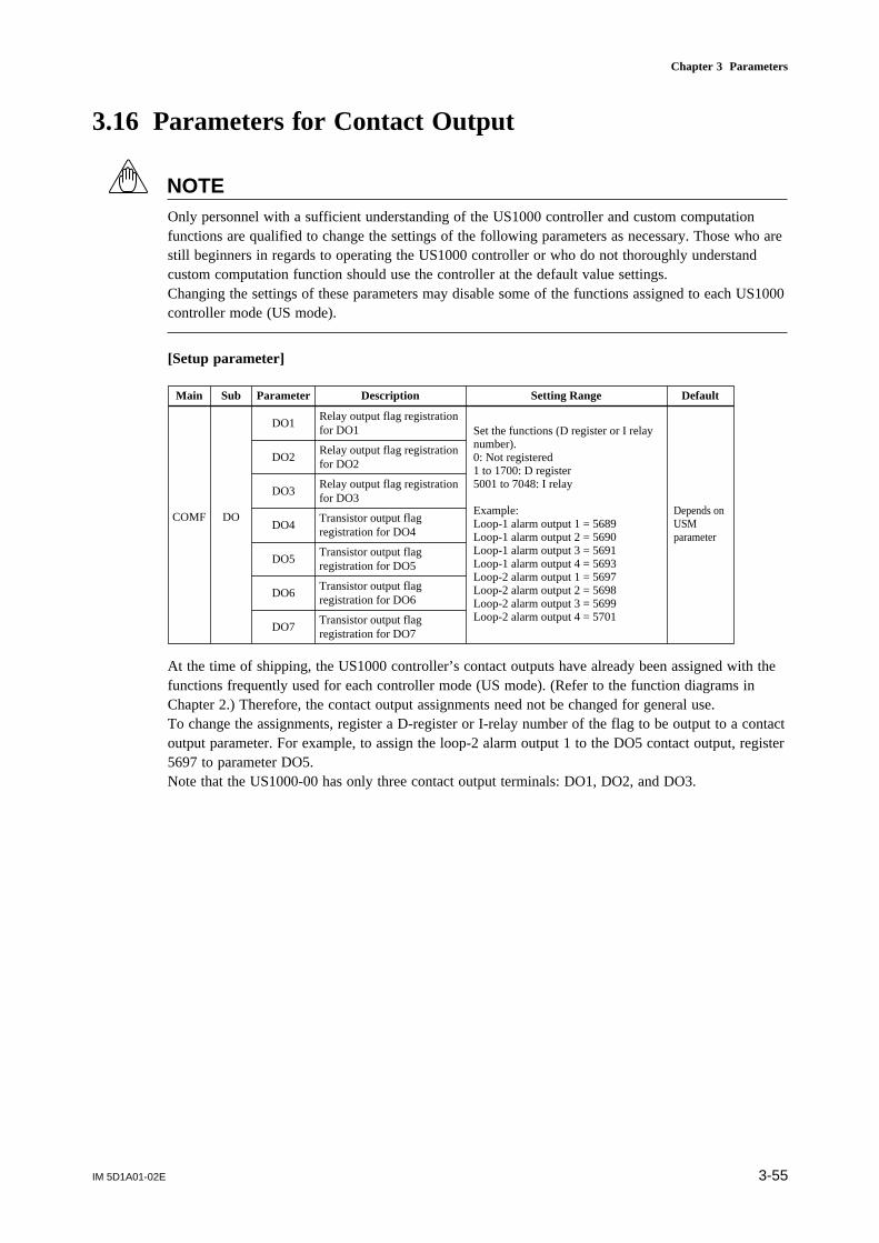
IM 5D1A01-02E 3-55
Chapter 3 Parameters
3.16 Parameters for Contact Output
NOTEOnly personnel with a sufficient understanding of the US1000 controller and custom computationfunctions are qualified to change the settings of the following parameters as necessary. Those who arestill beginners in regards to operating the US1000 controller or who do not thoroughly understandcustom computation function should use the controller at the default value settings.Changing the settings of these parameters may disable some of the functions assigned to each US1000controller mode (US mode).
[Setup parameter]
Main Sub Parameter Description Setting Range Default
COMF DO
DO1Relay output flag registration for DO1
DO2Relay output flag registration for DO2
DO3Relay output flag registration for DO3
DO4Transistor output flag registration for DO4
DO5Transistor output flag registration for DO5
DO6Transistor output flag registration for DO6
DO7Transistor output flag registration for DO7
Set the functions (D register or I relay number).0: Not registered1 to 1700: D register5001 to 7048: I relay
Example:Loop-1 alarm output 1 = 5689Loop-1 alarm output 2 = 5690Loop-1 alarm output 3 = 5691Loop-1 alarm output 4 = 5693Loop-2 alarm output 1 = 5697Loop-2 alarm output 2 = 5698Loop-2 alarm output 3 = 5699Loop-2 alarm output 4 = 5701
Depends on USM parameter
At the time of shipping, the US1000 controller’s contact outputs have already been assigned with thefunctions frequently used for each controller mode (US mode). (Refer to the function diagrams inChapter 2.) Therefore, the contact output assignments need not be changed for general use.To change the assignments, register a D-register or I-relay number of the flag to be output to a contactoutput parameter. For example, to assign the loop-2 alarm output 1 to the DO5 contact output, register5697 to parameter DO5.Note that the US1000-00 has only three contact output terminals: DO1, DO2, and DO3.

IM 5D1A01-02E3-56
3.17 Parameter that Determines Control Period[Setup parameter]
Main Sub Parameter Description Setting Range Default
USMD MD SMP Control period 50, 100, 200, 500 ms 200
NOTEChanging the control period clears the controller displays once and restarts the controller.
There are some restrictions as listed below on the use of the 50-ms, 100-ms, or 200-ms control period.If these conditions are not satisfied, the specified control period may not be achieved. There is norestriction when 500 ms is specified.
Restrictions on the 50-ms control period• Only applicable for the US1000-00 controller model.• Only applicable for the controller mode (US mode) of single-loop control.• SUPER function is disabled.• The following alarm types cannot be specified: high limit deviation (setting: 3, 5, 13, 15), low limit
deviation (setting: 4, 6, 14, 16), high and low limits deviation (setting: 7, 17), deviation within highand low limits (8, 18), self-diagnostic (setting: 27, 28), and FAIL output (setting: 29).
Restrictions on the 100-ms control period• Only applicable for the US1000-00 controller model.• Cascade control cannot be specified as the controller mode (US mode).
Restrictions on the 200-ms control period• When custom computation is to be used, a maximum of 30 computation modules is permitted.
It is possible to check whether or not the specified control period is appropriate by the USER displayof “sampling error counter.” The sampling error counter counts up once when all the control process-ing cannot be executed within the specified control period.
See Also Section 5.1, “Registering Auxiliary Operation Displays (USER Displays)” of the separate instructionmanual “US1000 Digital Indicating Controller” (IM 5D1A01-01E) for information about the samplingerror counter.

IM 5D1A01-02E 3-57
Chapter 3 Parameters
3.18 Parameters for Display Functions
3.18.1 USER Display
USER displays display data which are helpful during the controller operation.For information about USER displays, refer to Section 5.1, “Registering Auxiliary Operation Displays(USER Displays)” of the separate instruction manual “US1000 Digital Indicating Controller” (IM5D1A01-01E).
[Setup parameter]
Main Sub Parameter Description Setting Range Default
CONF U. OPE
U.1AL USER display of loop-1 alarm OFF, ON OFF
U.2AL USER display of loop-2 alarm OFF, ON OFF
U.SVN USER display of SV number OFF, ON OFF
U.1PI USER display of loop-1 PID group number OFF, ON OFF
U.2PI USER display of loop-2 PID group number OFF, ON OFF
U.AI1 USER display of AIN1 measured value OFF, ON OFF
U.AI2 USER display of AIN2 measured value OFF, ON OFF
U.AI3 USER display of AIN3 measured value OFF, ON OFF
U.PV1 USER display of PV1 OFF, ON OFF
U.PV2 USER display of PV2 OFF, ON OFF
U.SMP USER display of sampling error counter OFF, ON OFF
3.18.2 SELECT Display
SELECT displays permit easy callup of frequently accessed operation parameters from an operationdisplay.For information about SELECT displays, refer to Section 5.3, “Registering Quick Parameter Call-upFunctions (SELECT Displays)” of the separate instruction manual “US1000 Digital Indicating Con-troller” (IM 5D1A01-01E).
[Setup parameter]
Main Sub Parameter Description Setting Range Default
CONF C. SEL
C.S1 Registration for the SELECT display 1
C.S2 Registration for the SELECT display 2OFF, 201 to 773
C.S3 Registration for the SELECT display 3 OFF
C.S4 Registration for the SELECT display 4(see section 5.3)
C.S5 Registration for the SELECT display 5
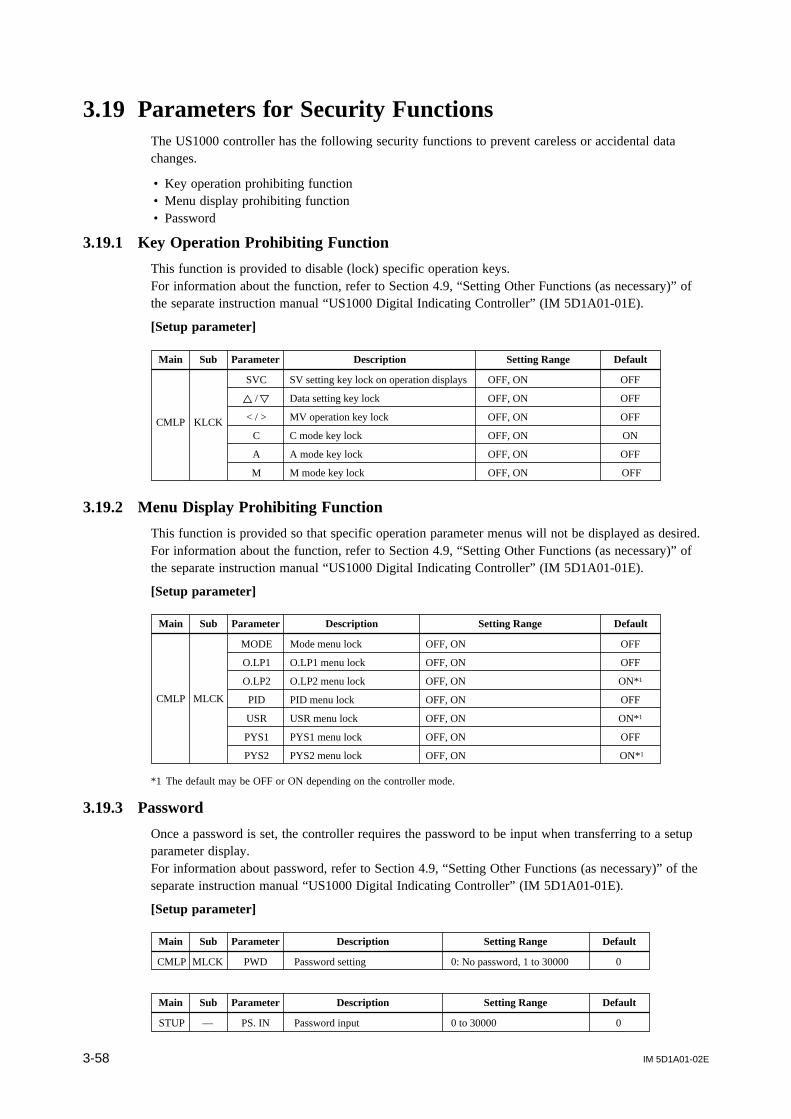
IM 5D1A01-02E3-58
3.19 Parameters for Security FunctionsThe US1000 controller has the following security functions to prevent careless or accidental datachanges.
• Key operation prohibiting function• Menu display prohibiting function• Password
3.19.1 Key Operation Prohibiting Function
This function is provided to disable (lock) specific operation keys.For information about the function, refer to Section 4.9, “Setting Other Functions (as necessary)” ofthe separate instruction manual “US1000 Digital Indicating Controller” (IM 5D1A01-01E).
[Setup parameter]
Main Sub Parameter Description Setting Range Default
CMLP KLCK
SVC SV setting key lock on operation displays OFF, ON OFF
/ Data setting key lock OFF, ON OFF
< / > MV operation key lock OFF, ON OFF
C C mode key lock OFF, ON ON
A A mode key lock OFF, ON OFF
M M mode key lock OFF, ON OFF
3.19.2 Menu Display Prohibiting Function
This function is provided so that specific operation parameter menus will not be displayed as desired.For information about the function, refer to Section 4.9, “Setting Other Functions (as necessary)” ofthe separate instruction manual “US1000 Digital Indicating Controller” (IM 5D1A01-01E).
[Setup parameter]
Main Sub Parameter Description Setting Range Default
CMLP MLCK
MODE Mode menu lock OFF, ON OFF
O.LP1 O.LP1 menu lock OFF, ON OFF
O.LP2 O.LP2 menu lock OFF, ON ON*1
PID PID menu lock OFF, ON OFF
USR USR menu lock OFF, ON ON*1
PYS1 PYS1 menu lock OFF, ON OFF
PYS2 PYS2 menu lock OFF, ON ON*1
*1 The default may be OFF or ON depending on the controller mode.
3.19.3 Password
Once a password is set, the controller requires the password to be input when transferring to a setupparameter display.For information about password, refer to Section 4.9, “Setting Other Functions (as necessary)” of theseparate instruction manual “US1000 Digital Indicating Controller” (IM 5D1A01-01E).
[Setup parameter]
Main Sub Parameter Description Setting Range Default
CMLP MLCK PWD Password setting 0: No password, 1 to 30000 0
Main Sub Parameter Description Setting Range Default
STUP — PS. IN Password input 0 to 30000 0
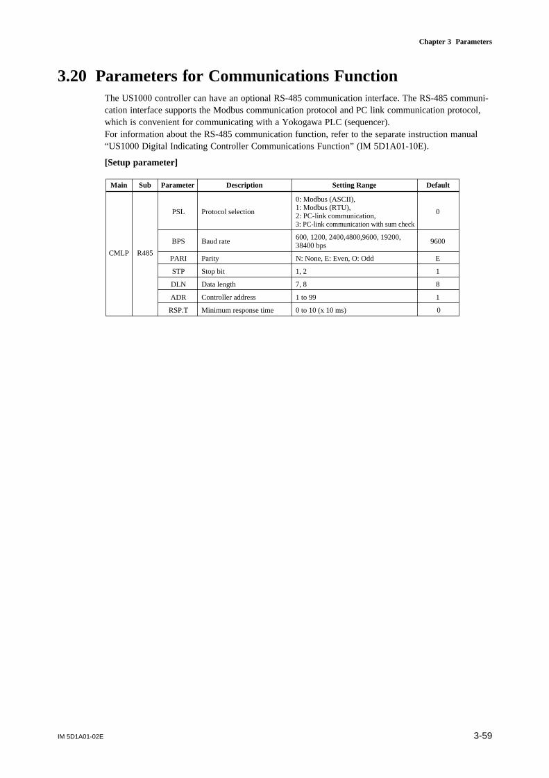
IM 5D1A01-02E 3-59
Chapter 3 Parameters
3.20 Parameters for Communications FunctionThe US1000 controller can have an optional RS-485 communication interface. The RS-485 communi-cation interface supports the Modbus communication protocol and PC link communication protocol,which is convenient for communicating with a Yokogawa PLC (sequencer).For information about the RS-485 communication function, refer to the separate instruction manual“US1000 Digital Indicating Controller Communications Function” (IM 5D1A01-10E).
[Setup parameter]
Main Sub Parameter Description Setting Range Default
CMLP R485
0: Modbus (ASCII),
PSL Protocol selection1: Modbus (RTU),
02: PC-link communication,3: PC-link communication with sum check
BPS Baud rate600, 1200, 2400,4800,9600, 19200,
960038400 bps
PARI Parity N: None, E: Even, O: Odd E
STP Stop bit 1, 2 1
DLN Data length 7, 8 8
ADR Controller address 1 to 99 1
RSP.T Minimum response time 0 to 10 (x 10 ms) 0
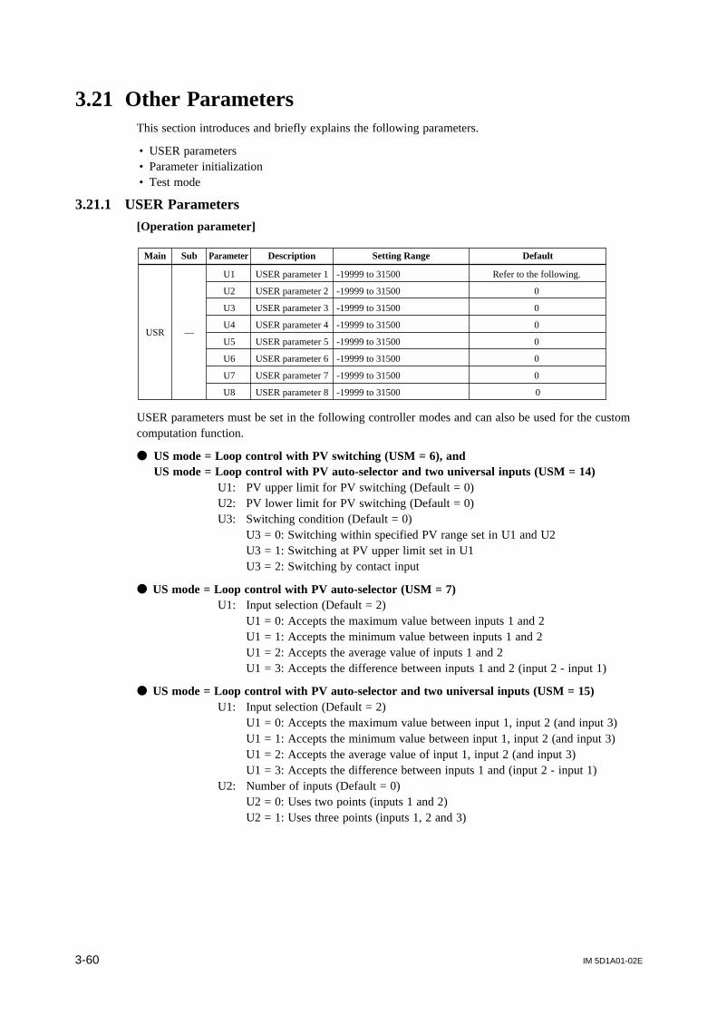
IM 5D1A01-02E3-60
3.21 Other ParametersThis section introduces and briefly explains the following parameters.
• USER parameters• Parameter initialization• Test mode
3.21.1 USER Parameters
[Operation parameter]
U1 USER parameter 1 -19999 to 31500 Refer to the following.
U2 USER parameter 2 -19999 to 31500 0
U3 USER parameter 3 -19999 to 31500 0
U4 USER parameter 4 -19999 to 31500 0
U5 USER parameter 5 -19999 to 31500 0
U6 USER parameter 6 -19999 to 31500 0
U7 USER parameter 7 -19999 to 31500 0
U8 USER parameter 8 -19999 to 31500 0
Main Sub Parameter Description Setting Range Default
USR —
USER parameters must be set in the following controller modes and can also be used for the customcomputation function.
US mode = Loop control with PV switching (USM = 6), andUS mode = Loop control with PV auto-selector and two universal inputs (USM = 14)
U1: PV upper limit for PV switching (Default = 0)U2: PV lower limit for PV switching (Default = 0)U3: Switching condition (Default = 0)
U3 = 0: Switching within specified PV range set in U1 and U2U3 = 1: Switching at PV upper limit set in U1U3 = 2: Switching by contact input
US mode = Loop control with PV auto-selector (USM = 7)U1: Input selection (Default = 2)
U1 = 0: Accepts the maximum value between inputs 1 and 2U1 = 1: Accepts the minimum value between inputs 1 and 2U1 = 2: Accepts the average value of inputs 1 and 2U1 = 3: Accepts the difference between inputs 1 and 2 (input 2 - input 1)
US mode = Loop control with PV auto-selector and two universal inputs (USM = 15)U1: Input selection (Default = 2)
U1 = 0: Accepts the maximum value between input 1, input 2 (and input 3)U1 = 1: Accepts the minimum value between input 1, input 2 (and input 3)U1 = 2: Accepts the average value of input 1, input 2 (and input 3)U1 = 3: Accepts the difference between inputs 1 and (input 2 - input 1)
U2: Number of inputs (Default = 0)U2 = 0: Uses two points (inputs 1 and 2)U2 = 1: Uses three points (inputs 1, 2 and 3)
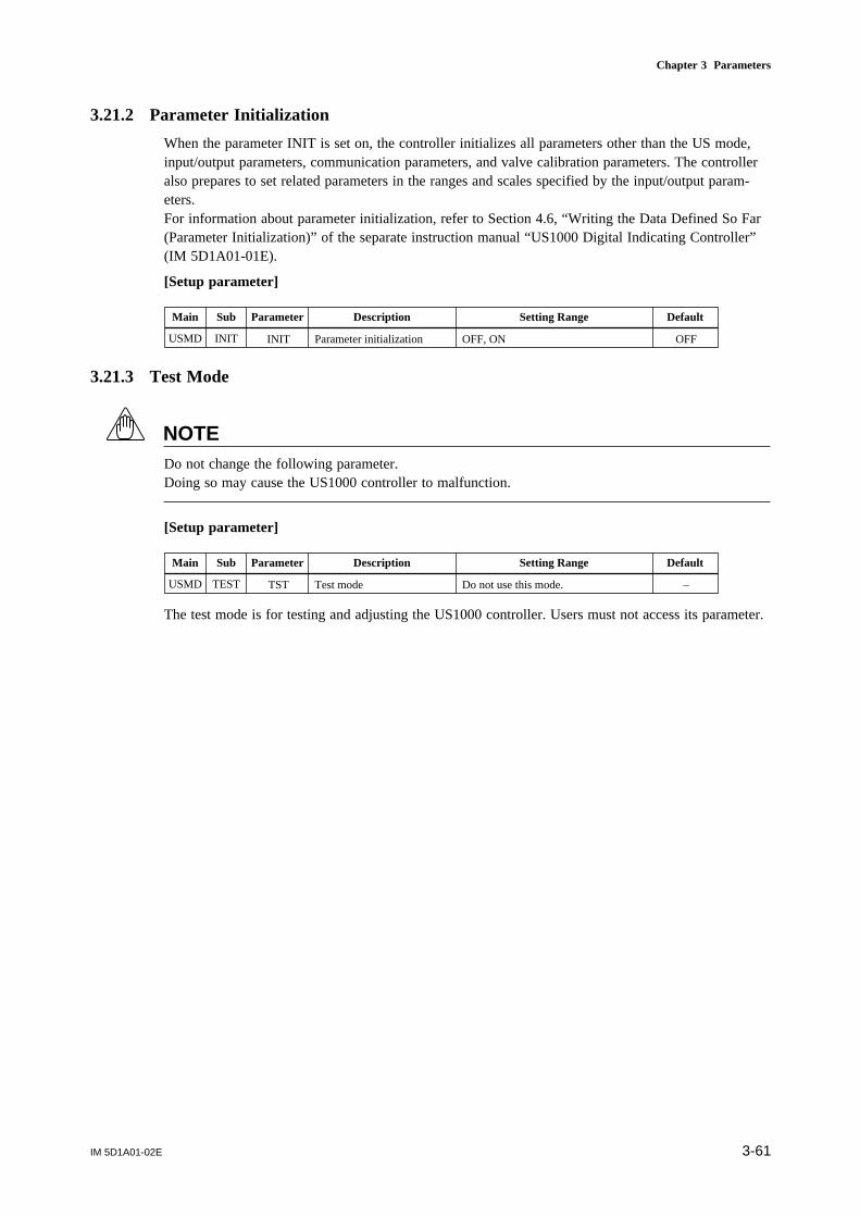
IM 5D1A01-02E 3-61
Chapter 3 Parameters
3.21.2 Parameter Initialization
When the parameter INIT is set on, the controller initializes all parameters other than the US mode,input/output parameters, communication parameters, and valve calibration parameters. The controlleralso prepares to set related parameters in the ranges and scales specified by the input/output param-eters.For information about parameter initialization, refer to Section 4.6, “Writing the Data Defined So Far(Parameter Initialization)” of the separate instruction manual “US1000 Digital Indicating Controller”(IM 5D1A01-01E).
[Setup parameter]
Main Sub Parameter Description Setting Range Default
USMD INIT INIT Parameter initialization OFF, ON OFF
3.21.3 Test Mode
NOTEDo not change the following parameter.Doing so may cause the US1000 controller to malfunction.
[Setup parameter]
Main Sub Parameter Description Setting Range Default
USMD TEST TST Test mode Do not use this mode. –
The test mode is for testing and adjusting the US1000 controller. Users must not access its parameter.

Blank Page

IM 5D1A01-02E App. 1-1
Appendix 1 Parameter Map
Appendix 1 Parameter Map
The parameter maps help you retrieve the desired parameters by showing the individual configurationdiagrams for the operation and setup parameter groups. Make use of this appendix together withparameter tables given in chapter 3 when setting parameters.
Some parameters are hidden (i.e., unavailable) depending on the model names or controller modes (USmodes).

IM 5D1A01-02EApp. 1-2
Operating Parameters
DISP
DISP
DISP
DISP
DISP
DISP DISP
SET/ENT
SET/ENT SET/ENT
SET/ENT
SET/ENT
SET/ENT
SET/ENT
SET/ENTSET/ENT SET/ENT
SET/ENT SET/ENTSET/ENT SET/ENTSET/ENT SET/ENTSET/ENTSET/ENT
3 sec.
3 sec.
Submenu Submenu
3 sec.
ATAuto-tuning
SUPERfunction
PV bias
PV filter
Setpointramp-up
Setpointramp-down
Cascade ratio
Cascade bias
Cascadeinput filter
Feedforwardgain
Feedforwardinput bias
Feedforwardoutput bias
Feedforwardinput filter
O/COPEN/CLOSEswitchover
SCSVNOSV numberselection
BS
UPR
FL
DNR
CRT
CBS
CFL
BS
UPR
DNR
CRT
CBS
FGN
FBI
FBO
FFL
1. SVTarget
setpoint
1. A1Alarm 1setpoint
1. A2Alarm 2setpoint
1. A4
1. A3Alarm 3setpoint
Alarm 4setpoint
1. PProportional
band
1. IIntegral time
1. DDerivative
time
1. MHUpper limitof output
1. MLLower limitof output
1. MRManual reset
1. HcCooling-siderelay hysteresis
1. HHysteresis
1. DRDirect/reverse
action
1. PcCooling-side
P1. Ic
Cooling-sideI
1. DcCooling-side
D
1. PMPreset MV
1. DBDeadband
1. RPZone PID
reference point
Cooling-sidepreset MV
1. PMc
7. SV
7. A1
7. A2
7. A4
7. A3
7. P
7. I
7. D
7. MH
7. ML
7. MR
7. Hc
7. H
7. DR
7. Pc
7. Ic
7. Dc
7. PM
7. DB
RHY
7. PMc
8. SV
8. A1
8. A2
8. A4
8. A3
8. P
8. I
8. D
8. MH
8. ML
8. MR
8. Hc
8. H
8. DR
8. Pc
8. Ic
8. Dc
8. PM
8. DB
RDV
8. PMc
DISP
SET/ENT
SET/ENT
SET/ENT SET/ENTSET/ENTSET/ENT
FL
CFL
1. SV
1. A1
1. A2
1. A4
1. A3
1. P
1. I
1. D
1. MH
1. ML
1. MR
1. Hc
1. H
1. DR
1. Pc
1. I c
1. Dc
1. PM
1. DB
1. RP
1. PMc
O.LP1Loop-1
operation menu
O.LP2Loop-2
operation menu
PARComputation
parameter1. PID 7. PID 8. PID
MODEMode menu
PARComputation
parameter1. PID
AT
SC
Operation display
Operation display 1 Operation display 2 Operation display 3 Operation display n USER display 1
SELECT display 1 SELECT display 2
Targetsetpoint
Alarm 1 setpoint
Alarm 2 setpoint
Alarm 3 setpoint
Alarm 4 setpoint
Proportional band
Integral time
Derivative time
Upper limit of output
Lower limit of output
Manual reset
Hysteresis
Direct/reverseaction
Cooling-side P
Cooling-side I
Cooling-side D
Cooling-side relay hysteresis
Deadband
Zone PID reference deviation
Preset MV
Cooling-side preset MV
Auto-tuning
SUPER function
PV bias
PV filter
Setpoint ramp-up
Setpoint ramp-down
Cascade ratio
Cascade bias
Cascade input filter
Target setpoint
Alarm 1 setpoint
Alarm 2 setpoint
Alarm 3 setpoint
Alarm 4 setpoint
Proportional band
Integraltime
Derivative time
Upper limit of output
Lower limit of output
Manual reset
Hysteresis
Direct/reverse action
Cooling-side P
Cooling-side I
Cooling-side D
Cooling-side relay hysteresis
Deadband
Zone PID reference point
Preset MV
Cooling-side preset MV
Targetsetpoint
Alarm 1 setpoint
Alarm 2 setpoint
Alarm 3 setpoint
Alarm 4 setpoint
Proportional band
Integral time
Derivative time
Upper limit of output
Lower limit of output
Manual reset
Hysteresis
Direct/reverse action
Cooling-side P
Cooling-side I
Cooling-side D
Cooling-side relay hysteresis
Deadband
Zone PID hysteresis
Preset MV
Cooling-side preset MV
To the original submenu
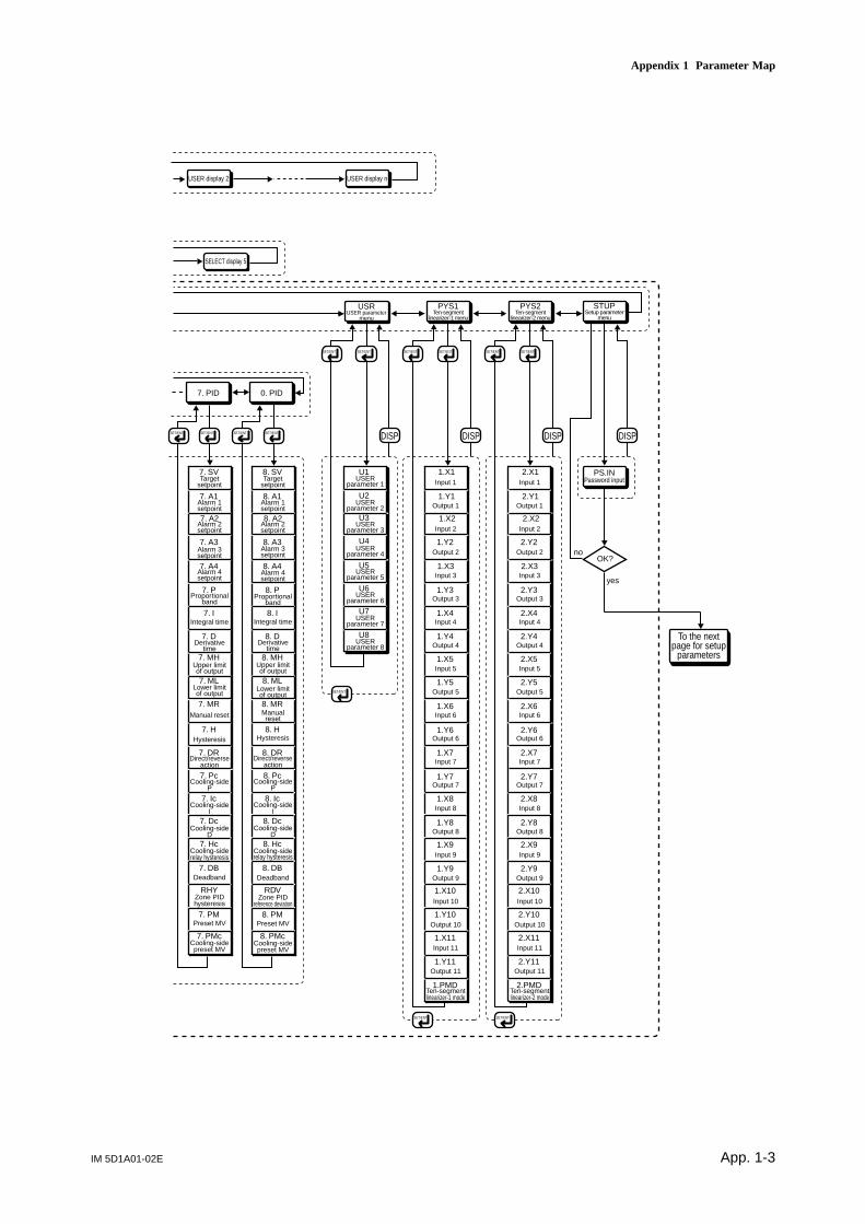
IM 5D1A01-02E App. 1-3
Appendix 1 Parameter Map
SET/ENTSET/ENT SET/ENTSET/ENT
U1
U2
U3
U4
U5
U6
U7
U8
7. SV
7. A1
7. A2
7. A4
7. A3
7. P
7. I
7. D
7. MH
7. ML
7. MR
7. Hc
7. H
7. DR
7. Pc
7. Ic
7. Dc
7. PM
7. DB
RHY
7. PMc
8. SV
8. A1
8. A2
8. A4
8. A3
8. P
8. I
8. D
8. MH
8. ML
8. MR
8. Hc
8. H
8. DR
8. Pc
8. Ic
8. Dc
8. PM
8. DB
RDV
8. PMc
1.X1
1.Y1
1.X2
1.X3
1.Y2
1.Y3
1.X4
1.Y4
1.X5
1.X6
1.Y5
1.Y6
1.X7
1.Y7
1.X8
1.Y8
1.X9
1.Y9
1.X10
1.Y10
1.X11
1.Y11
1.PMD
2.X1
2.Y1
OK?no
yes
2.X2
2.X3
2.Y2
2.Y3
2.X4
2.Y4
2.X5
2.X6
2.Y5
2.Y6
2.X7
2.Y7
2.X8
2.Y8
2.X9
2.Y9
2.X10
2.Y10
2.X11
2.Y11
2.PMD
SET/ENTSET/ENT
USRUSER parameter
menu
7. PID 0. PID
SET/ENT
DISP
SET/ENTSET/ENT
PYS1Ten-segment
linearizer-1 menu
SET/ENT
DISP
SET/ENTSET/ENT
PYS2Ten-segment
linearizer-2 menu
SET/ENT
DISP
PS.INPassword input
DISP
STUPSetup parameter
menu
USER display 2 USER display n
SELECT display 5
To the next page for setup
parameters
Target setpoint
Alarm 1 setpoint
Alarm 2 setpoint
Alarm 3 setpoint
Alarm 4 setpoint
Proportional band
Integral time
Derivative time
Upper limit of output
Lower limit of output
Manual reset
Hysteresis
Direct/reverse action
Cooling-side P
Cooling-side I
Cooling-side D
Cooling-side relay hysteresis
Deadband
Zone PID hysteresis
Preset MV
Cooling-side preset MV
Target setpoint
Alarm 1 setpoint
Alarm 2 setpoint
Alarm 3 setpoint
Alarm 4 setpoint
Proportional band
Integral time
Derivative time
Upper limit of output
Lower limit of output
Manual reset
Hysteresis
Direct/reverse action
Cooling-side P
Cooling-side I
Cooling-side D
Cooling-side relay hysteresis
Deadband
Zone PID reference deviation
Preset MV
Cooling-side preset MV
Input 1
Output 1
Input 2
Output 2
Input 3
Output 3
Input 4
Output 4
Input 5
Output 5
Input 6
Output 6
Input 7
Output 7
Input 8
Output 8
Input 9
Output 9
Input 10
Output 10
Input 11
Output 11
Ten-segment linearizer-1 mode
Input 1
Output 1
Input 2
Output 2
Input 3
Output 3
Input 4
Output 4
Input 5
Output 5
Input 6
Output 6
Input 7
Output 7
Input 8
Output 8
Input 9
Output 9
Input 10
Output 10
Input 11
Output 11
Ten-segment linearizer-2 mode
USER parameter 1
USER parameter 2
USER parameter 3
USER parameter 4
USER parameter 5
USER parameter 6
USER parameter 7
USER parameter 8

IM 5D1A01-02EApp. 1-4
Setup Parameters
SET/ENTSET/ENT
MODE
O.LP1
PWD
MLCK
O.LP2
PID
USR
PYS1
PYS2
DISP
DISP
SET/ENT
SET/ENT
SET/ENTSET/ENT SET/ENTSET/ENT SET/ENTSET/ENT
AL1
AL2
AL3
HY1
AL4
PVR.T
HY2
HY3
HY4
AMD
MVR
MOD
FFS
SVTarget
setpoint
O.LP1
DISP
S.LP1Loop-1
setup menu
S.LP2Loop-2
setup menu
ALMAlarmsetting
CTLControlfunction
AR
DISPSET/ENT
SET/ENTSET/ENT SET/ENTSET/ENT SET/ENTSET/ENT
CMS
PVT
TMU
DVB
CMS
PVT
TMU
DVB
AL1
AL2
AL3
HY1
AL4
PVR.T
AMD
HY2
HY3
HY4
MVR
MOD
SVTarget
setpoint
ALMAlarmsetting
CTLControlfunction
AR
SET/ENT
DISP
CMLPCommon
setup menu
DISPSET/ENT
SET/ENTSET/ENT SET/ENTSET/ENT
A.FL1
A.BS1
A.SR1
RET1
RTH1
SVC
/
< / >
C
A
M
A.BO1
A.RJ1
A.LC1
A.FL2
A.BS2
A.SR2
A.BO2
A.RJ2
A.LC2
A.FL3
A.BS3
A.SR3
A.BO3
A.LC3
PPID
AIN C.CTL
R.MD
R.TM
SET/ENTSET/ENT
KLCK
SET/ENTSET/ENT
RET
SET/ENTSET/ENT
DISP
SET/ENT
RTL1
RET2
RTH2
RTL2
RET3
RTH3
RTL3
3 sec.
CT1
CTc1
CTc2
CT2
From PS.IN password input on the previous page Loop-1
operation menu
Operationdisplay
Analog input computation
Retransmis-sion output Key lock Menu lockCommon
control setting
Cascade input selection
PV tracking selection
Time unit for ramp-rate
Deviation display range
Output ve-locity limiter
PID con-trol mode
Anti-reset windup
Feedforward input selection
Alarm 1 type
Alarm 2 type
Alarm 3 type
Alarm 4 type
Alarm 1 hysteresis
Alarm 2 hysteresis
Alarm 3 hysteresis
Alarm 4 hysteresis
PV velocity duration time
Alarm mode
Cascadeinput
PV tracking selection
Time unit for ramp-rate
Deviation dis-play range
Output ve-locity limiter
PID control mode
Anti-reset windup
Alarm 1 type
Alarm 2 type
Alarm 3 type
Alarm 4 type
Alarm 1 hysteresis
Alarm 2 hysteresis
Alarm 3 hysteresis
Alarm 4 hysteresis
PV velocity duration time
Alarm mode
Analog in-put-1 bias
Analog in-put-1 filter
Analog input-1 square-root
Square-root low signal cut off
Analog input-1 burnout action
Analog input-1 reference junction
Analog in-put-2 bias
Analog in-put-2 filter
Analog input-2 square-root
Square-root low signal cutoff
Analog input-2 burnout action
Analog input-2 reference junction
Analog in-put-3 bias
Analog in-put-3 filter
Analog input-3 square-root
Square-root low signal cutoff
Analog input-3 burnout action
Preset PID function
Restart mode
Restart timer
Cycle time of MV1
Cycle time of MV2
Cycle time of cooling MV1
Cycle time of cooling MV2
Ret. out-put-1 type
Max. value of ret. 1 scale
Min. value of ret. 1 scale
Ret. out-put-2 type
Max. value of ret. 2 scale
Min. value of ret. 2 scale
Ret. out-put-3 type
Max. value of ret. 3 scale
Min. value of ret. 3 scale
SV setting key lock
Data setting key lock
MV operation key lock
C mode key lock
A mode key lock
M mode key lock
Mode menu lock
O.LP1 menu lock
O.LP2 menu lock
PID menu lock
USR menu lock
PYS1 menu lock
PYS2 menu lock
Password setting
To the original submenu
To the original submenu
Submenu Submenu Submenu

IM 5D1A01-02E App. 1-5
Appendix 1 Parameter Map
OK?no
yes
USMDController function
setting menu
CONFDetailed function
setting menu
BPS
PSL
PARI
DLN
ADR
RSP.T
STP
SET/ENTSET/ENT
R485RS-485
DISP
DISPSET/ENT
SET/ENTSET/ENT SET/ENTSET/ENT SET/ENTSET/ENT
C.S1 U.1AL
U.1PI
U.2PI
U.AI1
U.PV1
U.PV2
U.AI2
U.AI3
U.SMP
U.2AL
U.SVN
C.S2
C.S3
C.S4
C.S5
DO1
DO3
C.SEL U.DPE DO
DO2
DO4
DO7
DO5
DO6
SET/ENTSET/ENT
PY1X
PY1Y
PY2X
PY2Y
C.PYS
SET/ENTSET/ENT
SET/ENT
DISP
DISPSET/ENT
SET/ENTSET/ENT SET/ENTSET/ENT SET/ENTSET/ENT
TYP1 V.RS
MD IN VALV
V.L
V.H
V.AT
SET/ENTSET/ENT
TSTUSM
UNI1
RH1
P.RH1
RL1
P.RL1
SDP1
P.DP1
P.RH2
P.RL2
P.DP2
SH1
SL1
TYP2
UNI2
RH2
RL2
SDP2
SH2
SL2
TYP3
RH3
RL3
SDP3
SH3
SL3
SMP
TEST
SET/ENTSET/ENT
INIT
INIT
SET/ENT
CAS1
AUT1
MAN1
CAS2
AUT2
MAN2
R/S
TRF1
TRF2
SV.B0
SV.B1
SV.B2
SV.B 3
DP1
DP2
MG1
MG2
MG3
MG4
DI
SET/ENTSET/ENT
MVS1
MVS2
A01
A02
A03
RVOP
OUTTen-segment linearizer unit
Controller mode Analog input Valve
calibrationMV output Test modeParameter initialization
To the original submenu
To the original submenu
Do not use this mode.
SELECT display setting
USER display setting
Contact output
Contact input
Protocol selection
Baud rate
Parity
Stop bit
Data length
Controller address
Min. re-sponse time
Registration for the SELECT 1
Registration for the SELECT 2
Registration for the SELECT 3
Registration for the SELECT 4
Registration for the SELECT 5
Loop-1 alarm
Loop-2 alarm
SV number
Loop-1 PID group number
Loop-2 PID group number
AIN1 meas-ured value
AIN2 meas-ured value
AIN3 meas-ured value
PV1
PV2
Sampling er-ror counter
Registration for DO1
Registration for DO2
Registration for DO3
Registration for DO4
Registration for DO5
Registration for DO6
Registration for DO7
Loop-1 mode switchover to CAS
Loop-1 mode switchover to AUTO
Loop-1 mode switchover to MAN
Loop-2 mode switchover to CAS
Loop-2 mode switchover to AUTO
Loop-2 mode switchover to MAN
RUN/STOP switchover
Loop-1 tracking flag
Loop-2 tracking flag
Bit-0 of SV number
Bit-1 of SV number
Bit-2 of SV number
Bit-3 of SV number
Interruptive display 1
Interruptive display 2
Interruptive message 1
Interruptive message 2
Interruptive message 3
Interruptive message 4
Inputunit 1
Output unit 1
Inputunit 2
Output unit 2
US mode
Control period
Input-1 type for AIN1 terminal
Input-1 unit
Max. value of input-1 range
Min. value of input-1 range
Input-1 decimal point position
Max. value of input-1 scale
Min. value of input-1 scale
Input-2 type for AIN2 terminal
Input-2 unit
Max. value of input-2 range
Min. value of input-2 range
Input-2 decimal point position
Max. value of input-2 scale
Min. value of input-2 scale
Input-3 type for AIN3 terminal
Max. value of input-3 range
Min. value of input-3 range
Input-3 decimal point position
Max. value of input-3 scale
Min. value of input-3 scale
PV1 decimal point position
Max. value of PV1 range
Mini. value of PV1 range
PV2 decimal point position
Max. value of PV2 range
Min. value of PV2 range
MV1selection
MV2selection
Output-1 type for OUT1A terminal
Output-2 type for OUT2A terminal
Output-3 type for OUT3A terminal
Reverse display and operation
Reset valve position
Fully-closed position
Fully-opened position
Automatic calibration
Parameter initialization Test mode
To the test mode
Submenu Submenu

Blank Page

Index-1IM 5D1A01-02E
Index
B
Balance-less and Bumpless Operation ................. 3-30Biasing ................................... 3-7, 3-10, 3-14, 3-15BPS .................................................................. 3-59BS .................................................................... 3-10Bumpless Tuning ............................................... 3-30Burnout ..................................................... 3-9, 3-43
C
C ...................................................................... 3-58C.S1 ................................................................. 3-57C.S2 ................................................................. 3-57C.S3 ................................................................. 3-57C.S4 ................................................................. 3-57C.S5 ................................................................. 3-57CAS/AUTO/MAN Mode Selection ....................... 2-3CAS1 ............................................................... 3-52CAS2 ............................................................... 3-52Cascade Bias ..................................................... 3-11Cascade CLOSE ................................................ 3-12Cascade Control (US1000-00) ............................ 2-13Cascade Control (US1000-1 1) ............................ 2-14Cascade Control (US1000-21) ............................ 2-15Cascade Control with Two Universal Inputs
(US1000-1 1) ............................................. 2-37Cascade Control with Two Universal Inputs
(US1000-21) ............................................ 2-38Cascade Input .............................................. 2-2, 3-1 1Cascade OPEN .................................................. 3-12Cascade Primary-loop Control (US1000-00) .......... 2-8Cascade Primary-loop Control (US1000-1 1) .......... 2-9Cascade Secondary-loop Control (US1000-00) ..... 2-10Cascade Secondary-loop Control (US1000-1 1) ..... 2-11Cascade Secondary-loop Control (US1000-21) ..... 2-12CBS ................................................................. 3-11CFL .................................................................. 3-11CMS ................................................................. 3-11COLD ................................................................ 3-2Communication Functions ............................ 2-2, 3-59Contact Input .............................................. 2-2, 3-52Contact Output ................................... 2-3, 3-46, 3-55Continuous PID Computation ............................. 3-23Control Action ................................................... 3-33Control Computation ......................................... 3-22Control Period ................................................... 3-56Controller Mode .................................................. 2-1CRT ................................................................. 3-11CTc1 ................................................................ 3-25CTc2 ................................................................ 3-25Cycle Time .............................................. 3-24, 3-25
Numbers
8-alarm ............................................................. 3-51
Symbols
</> ................................................................... 3-58∆/∇ .................................................................. 3-58
A
A...................................................................... 3-58A.BO1 ................................................................ 3-9A.BO2 ................................................................ 3-9A.BO3 ................................................................ 3-9A.BS1 ................................................................ 3-7A.BS2 ................................................................ 3-7A.BS3 ................................................................ 3-7A.FL1 ................................................................. 3-8A.FL2 ................................................................. 3-8A.FL3 ................................................................. 3-8A.LC1 ................................................................ 3-8A.LC2 ................................................................ 3-8A.LC3 ................................................................ 3-8A.RI1 ................................................................. 3-9A.RJ2 ................................................................. 3-9A.SR1 ................................................................ 3-8A.SR2 ................................................................ 3-8A.SR3 ................................................................ 3-8ADR................................................................. 3-59AL1.................................................................. 3-46AL2.................................................................. 3-46AL3.................................................................. 3-46AL4.................................................................. 3-46Alarm Outputs ................................................... 3-46Alarm Setpoint .................................................. 3-51Alarm with Waiting Action ................................. 3-47AMD................................................................ 3-46Analog Input ....................................................... 3-3Anti-reset W indup ............................................. 3-31AO1 ................................................................. 3-41AO2 ................................................................. 3-41AO3 ................................................................. 3-41Approximation .................................................. 3-15AR ................................................................... 3-31AT .................................................................... 3-38AUT1 ............................................................... 3-52AUT2 ............................................................... 3-52Auto-tuning ....................................................... 3-38
Index
IM 5D1A01-02EIndex-2
D
Deadband .......................................................... 3-26Decimal Point Position ......................................... 3-6Derivative Action .............................................. 3-29Deviation Display Range .................................... 3-21Direct/Reverse Action ........................................ 3-33Display Scale ...................................................... 3-6DLN................................................................. 3-59DNR ................................................................. 3-20DO1 ................................................................. 3-55DO2 ................................................................. 3-55DO3 ................................................................. 3-55DP1 .................................................................. 3-52DP2 .................................................................. 3-52Dry- and W et-bulb Calculations ............................ 3-5Dual-loop Control (US1000-1 1) ......................... 2-32
F
FAIL Output ...................................................... 3-51FBI ................................................................... 3-14FBO ................................................................. 3-14Feedforward Control .......................................... 3-13Feedforward Input ............................................. 3-13FFL .................................................................. 3-14FFS .................................................................. 3-13FGN ................................................................. 3-14Filter ...................................... 3-7, 3-10, 3-11, 3-14FL .................................................................... 3-10
H
Heating/cooling Computation ..................... 3-23, 3-25HOT ................................................................... 3-2HY1 ................................................................. 3-46HY2 ................................................................. 3-46HY3 ................................................................. 3-46HY4 ................................................................. 3-46Hysteresis ....................................... 3-25, 3-26, 3-36
I
INIT................................................................. 3-61Initialization ...................................................... 3-61Input Range ........................................................ 3-5Input Selection ......................................... 2-24, 2-42Input Type and Unit ............................................. 3-3Integral Action .................................................. 3-29Interruptive Message Display .............................. 3-54
K
Key Operation Prohibiting Function .................... 3-58
L
Loop Control for Backup (US1000-00) ................ 2-16Loop Control for Backup (US1000-1 1) ................ 2-17Loop Control for Backup (US1000-21) ................ 2-18Loop Control with PV Auto-selector .............. 3-5, 3-60Loop Control with PV Auto-selector
(US1000-00) ............................................ 2-25Loop Control with PV Auto-selector
(US1000-1 1) ............................................. 2-26Loop Control with PV Auto-selector
(US1000-21) ............................................ 2-27Loop Control with PV Auto-selector and
Two Universal Inputs (US1000-1 1) ............. 2-43Loop Control with PV Auto-selector and
Two Universal Inputs (US1000-21) ............ 2-44Loop Control with PV Auto-selector and Two
Universal Inputs ........................................ 3-60Loop Control with PV Switching .................. 3-5, 3-60Loop Control with PV Switching (US1000-00) ..... 2-21Loop Control with PV Switching (US1000-1 1) ..... 2-22Loop Control with PV Switching (US1000-21) ..... 2-23Loop Control with PV Switching and
Two Universal Inputs (US1000-1 1) ............. 2-40Loop Control with PV Switching and
Two Universal Inputs (US1000-21) ............ 2-41Loop Control with PV -hold Function
(US1000-00) ............................................ 2-29Loop Control with PV -hold Function
(US1000-1 1) ............................................. 2-30Loop Control with PV -hold Function
(US1000-21) ............................................ 2-31
M
M ..................................................................... 3-58MAN1 .............................................................. 3-52MAN2 .............................................................. 3-52Manual Reset .................................................... 3-32Menu Display Prohibiting Function ..................... 3-58MG1 ................................................................. 3-52MG2 ................................................................. 3-52MG3 ................................................................. 3-52MG4 ................................................................. 3-52MOD ................................................................ 3-30MODE .............................................................. 3-58MV Bar ............................................................ 3-44MV Decrease Key ............................................. 3-44MV Increase Key ............................................... 3-44MV Output .......................................... 2-3, 2-5, 3-41MV Output Type ................................................ 3-22MVR ................................................................ 3-43MVS1 .............................................. 2-5, 2-32, 3-22MVS2 .............................................. 2-5, 2-32, 3-22

Index-3IM 5D1A01-02E
Index
N
n.A1 ................................................................. 3-51n.A2 ................................................................. 3-51n.A3 ................................................................. 3-51n.A4 ................................................................. 3-51n.D ................................................................... 3-28n.DB ................................................................ 3-26n.Dc ................................................................. 3-30n.DR ................................................................ 3-33n.H ................................................................... 3-25n.I .................................................................... 3-28n.Ic ................................................................... 3-30n.MH ................................................................ 3-42n.ML ................................................................ 3-42n.MR ................................................................ 3-32n.P ................................................................... 3-28n.Pc .................................................................. 3-30n.PM ................................................................ 3-43n.PMc ............................................................... 3-43n.SV ................................................................. 3-18n.X1 ................................................................. 3-17n.Y1 ................................................................. 3-17Noise .................................................................. 3-7
O
O.LP1 ............................................................... 3-58O.LP2 ............................................................... 3-58O/C ......................................................... 3-12, 3-52Offset ............................................................... 3-32ON/OFF Computation ............................... 3-23, 3-25ON/OFF Switchings .......................................... 3-24OPEN/CLOSE .................................................. 2-13OPEN/CLOSE Switchover ................. 2-3, 3-12, 3-53Operating Parameters ................................... App. 1-2Operation Display for Interruption ...................... 3-54Operation Mode Switching ........................... 2-3, 3-53Output for US1000-1 1 .......................................... 2-5Output Limiter .................................................. 3-42Output Ranges ................................................... 3-41Output Rate-of-change Limiter ........................... 3-43Output Type ...................................................... 3-41Overshoot ................................................ 3-18, 3-31
P
P.DP1 ................................................................. 3-6P.DP2 ................................................................. 3-6P.RH1 ................................................................. 3-5P.RH2 ................................................................. 3-5P.RL1 ................................................................. 3-5P.RL2 ................................................................. 3-5Parameter Initialization ...................................... 3-61Parameter Map ............................................ App. 1-1PARI ................................................................ 3-59Passive Alarms .................................................. 3-47
Password .......................................................... 3-58PID .................................................................. 3-58PID Control Mode ............................................. 3-30PID Group ........................................................ 3-34PID Parameters ................................................. 3-28Position-proportional PID
Computation ............................ 2-7, 3-23, 3-27Power-on and Power Recovery ............................. 3-2PPID ....................................................... 3-34, 3-39Preset MV ......................................................... 3-43Preset PID ................................................ 3-34, 3-39Proportional Action ............................................ 3-28PS.IN ............................................................... 3-58PSL .................................................................. 3-59Pulse ................................................................ 3-24PV Auto-selector ...................................... 2-24, 2-42PV Bias ............................................................ 3-10PV Filter ........................................................... 3-10PV Input ............................................................. 2-2PV Range ............................................................ 3-5PV Switching ........................................... 2-19, 2-39PV Tracking ...................................................... 3-19PV-hold .............................................................. 2-3PVR.T .............................................................. 3-46PVT ................................................................. 3-19PWD ................................................................ 3-58PY1X ............................................................... 3-16PY1Y ............................................................... 3-16PY2X ............................................................... 3-16PY2Y ............................................................... 3-16PYS1 ................................................................ 3-58PYS2 ................................................................ 3-58
R
R.MD ................................................................. 3-2R.TM ................................................................. 3-2R/S ................................................................... 3-52Ramp Rate ........................................................ 3-20Range ........................................................ 3-5, 3-41Reference Deviation .......................................... 3-37Reference Junction Compensation ......................... 3-9Reference Points ................................................ 3-36Relative Humidity ............................................... 3-5Relay ....................................................... 3-24, 3-25Restart Mode ....................................................... 3-2Restart Timer ...................................................... 3-2RET1 ................................................................ 3-45RET2 ................................................................ 3-45RET3 ................................................................ 3-45Retransmission Output ................................. 2-3, 3-45Reversed Display and Operation ......................... 3-44Reversed Output ................................................ 3-41RH1 ................................................................... 3-5RH2 ................................................................... 3-5RH3 ................................................................... 3-5RL1 .................................................................... 3-5
IM 5D1A01-02EIndex-4
RL2 .................................................................... 3-5RL3 .................................................................... 3-5RS-485 ...................................................... 2-2, 3-59RSP.T ............................................................... 3-59RUN/STOP Switchover ..................... 2-3, 3-43, 3-53RVOP ............................................................... 3-44
S
SC .................................................................... 3-18Scale .......................................................... 3-6, 3-45SDP1 .................................................................. 3-6SDP2 .................................................................. 3-6SDP3 .................................................................. 3-6Security ............................................................ 3-58SELECT Display ............................................... 3-57Self-diagnostic Alarm ........................................ 3-50Setpoint Output Function .................................... 2-10Setup Parameters ......................................... App. 1-4SH1 .................................................................... 3-7SH2 .................................................................... 3-7SH3 .................................................................... 3-7SHUT ............................................................... 3-42Shutdown .......................................................... 3-42Single-loop Control (US1000-00) .......................... 2-4Single-loop Control (US1000-1 1) .......................... 2-5Single-loop Control (US1000-21) .......................... 2-7SL1 .................................................................... 3-7SL2 .................................................................... 3-7SL3 .................................................................... 3-7SMP ................................................................. 3-56Square-root Extraction ......................................... 3-8STP .................................................................. 3-59SUPER ............................................................. 3-18SV .................................................................... 3-18SV Bar Segment ................................................ 3-21SV Number .............................................. 3-34, 3-35SV Number Selection ......................................... 3-53SV Rate-of-change ............................................. 3-20SV.B0 ............................................................... 3-52SV.B1 ............................................................... 3-52SV.B2 ............................................................... 3-52SV.B3 ............................................................... 3-52SVC ................................................................. 3-58SVNO .............................................................. 3-35Switching Condition ................................. 2-19, 2-39
T
Target Setpoint .................................................. 3-18Temperature and Humidity Control
(US1000-1 1) ...................................... 2-35, 3-5Ten-segment Linearizer ...................................... 3-15Test Mode ......................................................... 3-61Thermocouple Inputs ........................................... 3-9Time-proportional PID Computation ................... 3-24
Time-proportional PID Computation with RelayOutput ..................................................... 3-23
Time-proportional PID Computation with V oltagePulse Output ............................................. 3-23
TMU ................................................................ 3-20Tracking ........................................................... 3-19Tracking Flag .................................................... 3-53Tracking Output ................................................ 2-10Tracking Switching .............................................. 2-3TRF1 ................................................................ 3-52TRF2 ................................................................ 3-52TST .................................................................. 3-61TYP1 .................................................................. 3-3TYP2 .................................................................. 3-3TYP3 .................................................................. 3-3
U
U.1AL .............................................................. 3-57U.1PI ................................................................ 3-57U.2AL .............................................................. 3-57U.2PI ................................................................ 3-57U.AI1 ............................................................... 3-57U.AI2 ............................................................... 3-57U.AI3 ............................................................... 3-57U.PV1 .............................................................. 3-57U.PV2 .............................................................. 3-57U.SMP ............................................................. 3-57U.SVN ............................................................. 3-57U1 .................................................................... 3-60U2 .................................................................... 3-60U3 .................................................................... 3-60UNI1 .................................................................. 3-3UNI2 .................................................................. 3-3UPR ................................................................. 3-20US Mode ............................................................ 2-1USER Display ................................................... 3-57USER Parameter ........... 2-19, 2-24, 2-39, 2-42, 3-60USM .................................................................. 2-1USR ................................................................. 3-58
V
V.AT ................................................................. 3-27V.H ................................................................... 3-27V.L ................................................................... 3-27V.RS ................................................................. 3-27Valve .............................................. 3-27, 3-42, 3-44Valve Position Feedback ....................................... 2-7Voltage Pulse ..................................................... 3-24
Z
Zone PID ........................................ 3-34, 3-35, 3-39

i
Written by Yokogawa Electric Corporation
Published by Yokogawa Electric Corporation2-9-32 Nakacho, Musashino-shi, Tokyo 180-8750,JAPAN
Revision RecordManual Title: Model US1000 Digital Indicating Controller FunctionsManual number: IM 5D1A01-02E
Revised ItemDataEdition
First
Second
Aug., 1998
Jun., 2004
Newly published.
Change of the company name.

Blank Page

YOKOGAWA ELECTRIC CORPORATION
Network Solutions Business Division2-9-32, Nakacho, Musashino-shi, Tokyo, 180-8750 JAPANPhone: +81-422-52-7179 Facsimile: +81-422-52-6793Sales Branch OfficesTokyo, Nagoya, Osaka, Hiroshima, Fukuoka
YOKOGAWA CORPORATION OF AMERICA
Headquaters2 Dart Road, Newnan, GA. 30265-1094 U.S.A.Phone: +1-770-253-7000 Facsimile: +1-770-251-0928Sales Branch Offices / Texas, Chicago, Detroit, San Jose
YOKOGAWA EUROPE B. V.
HeadquatersDatabankweg 20, 3821 AL Amersfoort THE NETHERLANDSPhone: +31-334-64-1611 Facsimile: +31-334-64-1610Sales Branch Offices / Houten (The Netherlands), Wien (Austria), Zaventem(Belgium), Ratingen (Germany), Madrid (Spain), Bratislava (Slovakia), Runcorn (UnitedKingdom), Milano (Italy), Velizy villacoublay(France), Johannesburg(Republic of SouthAfrica)
YOKOGAWA AMERICA DO SUL S.A.
Headquarters & PlantPraca Acapulco, 31-Santo Amaro, Sao Paulo/SP, BRAZIL CEP-04675-190Phone: +55-11-5681-2400 Facsimile: +55-11-5681-4434
YOKOGAWA ENGINEERING ASIA PTE. LTD.
Head office5 Bedok South Road, Singapore 469270 SINGAPOREPhone: +65-6241-9933 Facsimile: +65-6241-2606
YOKOGAWA ELECTRIC KOREA CO., LTD.
Seoul Sales office395-70, Shindaebang-dong, Dongjak-gu, Seoul,156-010, KOREAPhone: +82-2-3284-3000 Facsimile: +82-2-3284-3019
YOKOGAWA TAIWAN CORPORATION
Head office17F, No.39, Sec. 1, Chung Hwa Road Taipei, 100 TAIWANPhone: +886-2-2314-9166 Facsimile: +886-2-2314-9918
YOKOGAWA AUSTRALIA PTY. LTD.
Head officeCentrecourt D1, 25-27 Paul Street North, North Ryde, N. S. W. 2113, AUSTRALIAPhone: +61-2-9805-0699 Facsimile: +61-2-9888-1844
YOKOGAWA INDIA LTD.
Head office40/4 Lavelle Road, Bangalore, 560 001, INDIAPhone: +91-80-227-1513 Facsimile: +91-80-227-4270
LTD. YOKOGAWA ELECTRIC
Grokholskiy per. 13, Build. 2, 4th Floor, 129010, Moscow, RUSSIA FEDERATIONPhone: +7-095-737-7868 Facsimile: +7-095-737-7869