v lw r - seitron.com · significa che c'è un'errore di comunicazione del modulo ingressi...
TRANSCRIPT

��������������
AC DS01 0001 SE 021885A0 140313 - ITALIANO -
$&�'6��������6(��
6<67(0�021,725�&21�&2081,&$=,21(�6(5,$/(�56����6(&21'2�,/�35272&2//2�6�%86
V H L W U R Q9LD�3URVGRFLPR�����
,�������%$66$12�'(/�*5$33$��9,��7HO�������������������)D[�������������������KWWS���ZZZ�VHLWURQ�LW�H�PDLO��LQIR#VHLWURQ�LW�
*(1(5$/,7$���Il system monitor, dotato di comunicazione seriale RS485 secondo il protocollo S-Bus, svolge la funzione di monitor remoto in un sistema di rilevazione gas. Il dispositivo normalmente mostrerà sul display LCD, retroilluminato, i dati che gli vengono inviati dalla centralina gas, ovvero lo stato degli ingressi, delle uscite (normale funzionamento, preallarme, allarme o guasto) e dei trasmettitori, mediante delle apposite icone presenti sul display. )81=,21$0(172�Appena alimentato, il system monitor effettuerà una diagnosi del circuito interno per verificarne il corretto funzionamento; sul display verranno visualizzate le seguenti informazioni:
�������������������������������������� �
)LU��[[[[[[�$������������������������� �
�������������������������������������� �
�������������������������������������� �
�������������������������������������� �
�������������������������������������� �
�������������������������������������� �
�������������������������������������� �
�������������������������������������� �
�
dove ’ xxxxxx ’ e’ la versione del firmware installato. Questi dati rimangono visibili per circa 2 secondi. Dopo questo tempo comparira’ la schermata principale con l'icona ' ' lampeggiante ad indicare la corretta comunicazione tra system monitor e centralina gas (esempio):
�������������������������������������� �
�Q(W��&RQWUR/����RQ������������������� �
�������������������������������������� ������������������������
�������������������������������������� �
�������������������������������������� �
�������������������������������������� �
�������������������������������������� �
�������������������������������������� �
�������������������������������������� �
6(*1$/$=,21(�$&867,&$�Il system monitor dispone di un buzzer interno che gli consente di emettere una segnalazione acustica in caso di allarme o guasto. La segnalazione acustica non è escludibile. �
9,68$/,==$=,21,�Il system monitor normalmente mostrerà sul display alfanumerico i dati trasmessi dalla centralina gas collegata, verificando l'integrità dei dati ricevuti. 1RUPDOH�IXQ]LRQDPHQWR�GHL�WUDVPHWWRWRUL�Il system monitor visualizza le icone dei trasmettitori collegati alla centralina. Lo stato di ogni trasmettitore verrà mostrato mediante delle apposite icone presenti sul display; se le icone sono fisse significa che il trasmettitore funziona correttamente. Esempio:
�������������������������������������� �
�Q(W��&RQWUR/����RQ������������������� �
�������������������������������������� ���������
�������������������������������������� �
�������������������������������������� �
�������������������������������������� �
�������������������������������������� �
�������������������������������������� �
�������������������������������������� �
�
$QRPDOLH�GHL�WUDVPHWWLWRUL�Se il system monitor emette una segnalazione acustica e contemporaneamente l'icona di un trasmettitore è lampeggiante significa che è stata rilevata dalla centralina gas una situazione anomala (es. preallarme, allarme e/o guasto, errore di comunicazione, ecc.). Il system monitor visualizzerà ciclicamente, oltre all'icona lampeggiante del trasmettitore che ha rilevato l'errore, le informazioni relative a tutte le uscite (in accordo con la logica impostata), della centralina gas e a tutti gli ingressi, se precedentemente era stato collegato un modulo ingressi. Esempio di visualizzazione:
�������������������������������������� �
�28W��3U(��2Q������������������������� �
�������������������������������������� ���������
�������������������������������������� �
�������������������������������������� �
�������������������������������������� �
�������������������������������������� �
�������������������������������������� �
�������������������������������������� �
Di seguito sono riportate tutte le informazioni, che
)LJ�����Aspetto esteriore�
1
��������������
AC DS01 0001 SE 021885A0 140313 - ITALIANO -
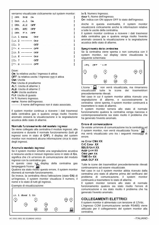
verranno visualizzate ciclicamente sul system monitor: �
�28W��3U(��2Q������������������������� ��
�28W��$/���2Q������������������������� ��
�28W��$/���2))������������������������ ��
�28W��$8+��2))������������������������ ��
�28W��)/W��2))������������������������ ��
,Q���QDPH����2))���������������������� �������������������������
,Q�����������2))���������������������� �������������������������
,Q�����������2))���������������������� �������������������������
,Q�����������2))���������������������� �������������������������
,Q�����������2))���������������������� �������������������������
,Q�����������2))���������������������� �������������������������
,Q�����������2))���������������������� �������������������������
,Q�����������2))���������������������� ������������������������
Dove: 2Q: la relativa uscita / ingresso è attiva 2)): la relativa uscita / ingresso non è attiva 2XW� Uscita 3UH� Uscita di preallarme $/�� Uscita di allarme 1�$/�� Uscita di allarme 2�$8+� Uscita ausliaria�)/W� Uscita di guasto�,Q����Numero Ingresso. QDPH� Nome dell'ingresso. ---------: il nome dell'ingresso non è stato associato.� Il system monitor continua a ricevere i dati trasmessi dalla centralina gas e qualora venga risolto l'evento anomalo cesserà la visualizzazione e la segnalazione acustica dello stato di allarme. ��1RUPDOH�IXQ]LRQDPHQWR�GHO�PRGXOR�LQJUHVVL�Se viene collegato alla centralina il modulo ingressi, alla scansione e durante il normale funzionamento (tutti gli ingressi sono in stato di 2))), il display del system monitor non mostrerà alcuna informazione circa lo stato degli ingressi. $QRPDOLH�PRGXOR�LQJUHVVL�Se il system monitor emette una segnalazione acustica e nessuna uscita e nessun ingresso sono in stato di 2Q, significa che c'è un'errore di comunicazione del modulo ingressi con la centralina gas. In questo caso sul display della centralina gas lampeggerà l'icona ' '. Qualora sia stato risolto questo errore, il system monitor ritornerà al normale funzionamento. Se invece, la centralina rileva l'attivazione (stato 21) di un'ingresso, il system monitor visualizza il numero, il nome e lo stato di tutti gli ingressi.
Esempio di visualizzazione:
�������������������������������������� �
�������������������������������������� �
,Q���GRRU���2Q������������������������ ������������������������
�������������������������������������� �
�������������������������������������� �
�������������������������������������� �
�������������������������������������� �
�������������������������������������� �
�������������������������������������� �
�
,Q����Numero Ingresso. GRRU��� Nome dell'ingresso. 2Q��indica con ON oppure OFF lo stato dell'ingresso.
Anche in questa eventualità, il system monitor visualizzerà ciclicamente anche le informazioni relative a tutte le uscite della centralina. Il system monitor continua a ricevere i dati trasmessi dalla centralina gas e qualora venga risolto l'evento anomalo cesserà la visualizzazione e la segnalazione acustica dello stato di allarme.��6SHJQLPHQWR�GHOOD�FHQWUDOLQD�Se la centralina viene spenta o non comunica con il system monitor, sul display viene visualizzata la seguente schermata:
�������������������������������������� �
�Q(W��2))��OLQ(����������������������� �
�������������������������������������� ���������
�������������������������������������� �
�������������������������������������� �
�������������������������������������� �
�������������������������������������� �
�������������������������������������� �
�������������������������������������� �
�
L'icona ' ' non verrà visualizzata, ma rimarranno visualizzate tutte le icone dei trasmettitori precedentemente rilevati. Nel caso in cui il system monitor abbia ricevuto una segnalazione di allarme, e successivamente la centralina viene spenta, il system monitor continuerà a trasmettere lo stato di allarme. Il system monitor tornerà allo stato di normale funzionamento qualora la centralina venga riaccesa e contemporaneamente sia stato risolto il problema che ha generato l'evento anomalo. (UURUH�GL�FRPXQLFD]LRQH�Se esiste un'errore di comunicazione tra la centralina ed il system monitor, non verrà visualizzata l'icona ' ', ma verrà visualizzato uno tra i seguenti messaggi di errore.
QR�(UURU�&0G�;;�&U&�(UURU��;;�6%86�8Q+�;;�$GGU�8Q+�;;�&0G�8Q+�;;�7L0(�(UU�;;�G$W$�28)�;;�
Tutte le icone dei trasmettitori precedentemente rilevati continueranno ad essere visualizzate. Nel caso in cui il system monitor abbia ricevuto dalla centralina uno stato di allarme prima del verificarsi del problema di comunicazione, il system monitor continuerà a trasmettere lo stato di allarme. Il system monitor tornerà allo stato di normale funzionamento qualora sia stato risolto l'errore di comunicazione e sia stato risolto il problema che ha generato l'evento anomalo.
&2//(*$0(17,�(/(775,&,�Il system monitor è alimentato con tensione di 12Vdc. L'ingresso COM (comunicazione seriale RS485) viene utilizzato per il collegamento del system monitor alla centralina.
2

��������������
AC DS01 0001 SE 021885A0 140313 - ITALIANO -
Il System monitor non necessita di impostazione del numero identificativo. Per i collegamenti elettrici si rimanda allo schema di collegamento di Fig. 2.
Per maggiori informazioni, leggere attentamente il manuale istruzione della centralina gas. 5HVLVWHQ]D�GL�WHUPLQD]LRQH�GD�����2KP��I dispositivi terminali della rete RS485 (ovvero quei dispositivi che sono collegati ai due capi della rete RS485 - vedere gli esempi riportati in Fig. 3 e Fig. 4) devono avere attivata la resistenza di terminazione da 120 Ohm. La resistenza di terminazione sul system monitor si attiva inserendo il ponticello jumper in dotazione, sul connettore -3�� �YHGL� LO� SXQWR� QXPHUR� ��� QHO�SDUDJUDIR��,167$//$=,21(��. 1RQ� DWWLYDUH� SL�� GL� GXH� UHVLVWHQ]H� GL� WHUPLQD]LRQH�SHU�LPSLDQWR���
&$5$77(5,67,&+(�7(&1,&+(�Alimentazione: 12V= ±10%. Assorbimento: 40 mA Protocollo di comunicazione: S-Bus Grado di protezione: IP 30 Temp. funzionamento: 0°C .. 40°C Temp. stoccaggio: -10°C .. +50°C Limiti di umidita': 20% .. 80% RH (non condensante) Contenitore: Materiale: ABS V0 auto-estinguente Colore: Bianco Segnale (RAL 9003) Dimensioni: 156 x 108 x 47 mm (LxAxP) Peso: ~ 550 gr. 5,)(5,0(17,�1250$7,9, Il prodotto è conforme alle direttive EMC 2004/108/F e LVD 2006/95/F.
,167$//$=,21(�
3(5� ,167$//$5(� ,/� ',6326,7,92�� (6(*8,5(� /(�6(*8(17,�23(5$=,21,���
���Togliere la vite indicata e rimuovere lo sportellino.
�� Togliere le 2 viti indicate e separare la calotta con
l’elettronica applicata dalla base.
�� 0217$**,2��,1*5(662��&$9,��68/��5(752� Se l’installazione non prevede l’uso dei fermacavi
(in dotazione), rimuovere, con l’aiuto di un cacciavite, i tasselli della base occorrenti per far passare i cavi, e al punto 6 inserire i tasselli in dotazione.
�� Fissare la base del system monitor alla parete. ����
3
130 130 mm

��������������
AC DS01 0001 SE 021885A0 140313 - ITALIANO -
�� Se il system monitor sarà un elemento di terminazio-ne nella rete RS485, inserire il Jumper in dotazione sul connettore $.� Il connettore è posto sull'elettronica applicata alla calotta, come visibile nell'immagine seguente:
Jumper in dotazione �
D�$77(1=,21(�
3HU� PDJJLRUL� LQIRUPD]LRQL� VXOOD� UHVLVWHQ]D� GL�WHUPLQD]LRQH�� YHGHUH� LO� SDUDJUDIR� � 5HVLVWHQ]D� GL�WHUPLQD]LRQH�GD�����2KP��D�SDJLQD����
��� Reinserire la calotta con l’elettronica alla base. ������
�� 0217$**,2� &21� ,1*5(662� &$9,� 68/� /$72�,1)(5,25(��
Inserire i fermacavi e/o i tasselli in dotazione.
�� Eseguire i collegamenti elettrici (vedi paragrafo ' collegamenti elettrici ').
�� Chiudere il system monitor reinserendo lo sportellino.
D�$77(1=,21(�
1HO� FKLXGHUH� LO� V\VWHP�PRQLWRU� DFFHUWDUVL� FKH� OH�PRUVHWWLHUH�HVWUDLELOL�VLDQR�VWDWH�LQVHULWH�FRUUHWWD�PHQWH� �OH� YLWL� GHOOH� PRUVHWWLHUH� GHYRQR� HVVHUH�ULYROWH�YHUVR�O¶DOWR���
D�$77(1=,21(��� ,O�V\VWHP�PRQLWRU�121�(� LGRQHR�SHU� OLQVWDOOD]LR�QH�LQ�]RQH�FODVVLILFDWH�$7(;��
�� 6H� OLQVWDOOD]LRQH�DYYLHQH� LQ�DPELHQWL�FRQ�SUHVHQ�]D� GL� IRUWL� GLVWXUEL� (0&�� H� IRUWHPHQWH� UDFFRPDQ�GDWR�OXVR�GL�FDYL�VFKHUPDWL��
�� 3HU� OD� VFHOWD� GHL� FDYL� GD� XWLOL]]DUH� SHU� LO� FROOHJD�PHQWR�DOOD�UHWH�56����H�SHU�OD�OLQHD�GL�DOLPHQWD]LR�QH� ULIHULUVL� DO� PDQXDOH� LVWUX]LRQH� GHOOD� FHQWUDOLQD�JDV���
�� /LQVWDOOD]LRQH�HG�L�FROOHJDPHQWL�HOHWWULFL�GL�TXHVWR�GLVSRVLWLYR� GHYRQR� HVVHUH� HVHJXLWL� GD� WHFQLFL�TXDOLILFDWL� HG� LQ� FRQIRUPLWD� FRQ� OH� YLJHQWL� QRUPH�WHFQLFKH�H�GL�VLFXUH]]D���
�� 3ULPD�GL� HIIHWWXDUH� L� FROOHJDPHQWL� HOHWWULFL� DVVLFX�UDUVL�GL�WRJOLHUH�WHQVLRQH�GDOOLPSLDQWR��
�� (� FRPSLWR� GHOOLQVWDOODWRUH� DOOHVWLUH� VRWWR� OD� SUR�SULD�UHVSRQVDELOLWD�XQ�VLVWHPD�GL�ULYHOD]LRQH�FRQ�IRUPH�DOOH�QRUPH�HVLVWHQWL��VLD�1D]LRQDOL�FKH�(XUR�SHH��H�VFHJOLHUH�JOL�DGHJXDWL�WLSL�GL�FDULFR�GD�FROOH�JDUH� DOOD� FHQWUDOLQD� QRQFKH� FRQILJXUDUH� FRUUHWWD�PHQWH� L� SDUDPHWUL� GHO� VLVWHPD�� ,Q� FDVR� GL� GXEEL�FRQWDWWDUH�LO�GLVWULEXWRUH��
*$5$1=,$�Nell'ottica di un continuo sviluppo dei propri prodotti, il costruttore si riserva il diritto di apportare modifiche a dati tecnici e prestazioni senza preavviso. Il consumatore è garantito contro i difetti di conformità del prodotto secondo la Direttiva Europea 1999/44/F nonché il documento sulla politica di garanzia del co-struttore. Su richiesta è disponibile presso il venditore il testo completo della garanzia.
4
$

��������������
AC DS01 0001 SE 021885A0 140313 - ITALIANO - 5
)LJ���: Esempio di collegamento, con alimentazione separata e con terminazione: Centralina (primo dispositivo del Bus) - Trasmettitore (ultimo dispositivo del Bus).
�����7[�&2�Resistenza di terminazione da 120 Ohm
DWWLYDWD
A B
RS 485
+
COM 12Vdc
Resistenza di terminazione da 120 Ohm DWWLYDWD sulla centralina: PONTICELLO INSERITO
����7[�&+��Resistenza di terminazione da 120 Ohm disattivata
����6<67(0�021,725�
Resistenza di terminazione da 120 Ohm disattivata
)LJ���: Esempio di collegamento, con alimentazione separata e con terminazione: System monitor (primo dispositivo del Bus) - Modulo ingressi (ultimo dispositivo del Bus).
A B
RS 485
+
COM 12Vdc
Resistenza di terminazione da 120 Ohm disattivata sulla centralina: PONTICELLO NON INSERITO
����7[�&+��Resistenza di terminazione da 120 Ohm disattivata
����6<67(0�021,725�
Resistenza di terminazione da 120 Ohm DWWLYDWD
�����02'8/2�,1*5(66,�
Resistenza di terminazione da 120 Ohm DWWLYDWD
)LJ�����Schema di collegamento�
1819 2 1
12VRS485BA

��������������
AC DS01 0001 SE 021885A0 140313 - ENGLISH -
$&�'6��������6(��
6<67(0�021,725�:,7+�56����6(5,$/�&20081,&$7,21�$&&25',1*�72�6�%86�35272&2/
V H L W U R Q9LD�3URVGRFLPR�����
,�������%$66$12�'(/�*5$33$��9,��7HO�������������������)D[�������������������KWWS���ZZZ�VHLWURQ�LW�H�PDLO��LQIR#VHLWURQ�LW�
29(59,(:���This system monitor, featuring RS485 serial communication according to the S-Bus protocol, accomplishes the function of a remote monitor in a gas detection system. The device will show on the backlit LCD display all the data sent by the gas central unit. i.e. the status of inputs, of the outputs (normal operation, prealarm, alarm and fault) as well as of the transmitters, through the specific icons arranged on the display. 23(5$7,21�As soon as powered, the system monitor will perform a diagnosis of the internal circuitry for a check of the proper operation; on the display the following information will be shown:
�������������������������������������� �
)LU��[[[[[[�$������������������������� �
�������������������������������������� �
�������������������������������������� �
�������������������������������������� �
�������������������������������������� �
�������������������������������������� �
�������������������������������������� �
�������������������������������������� �
�
where ’ xxxxxx ’ is the version of the firmware. These data are shown for 2 seconds. After this time will be shown the main screen with the icon ' ' flashing, thus meaning that proper communication between the system monitor and the gas central unit is taking place (example):
�������������������������������������� �
�Q(W��&RQWUR/����RQ������������������� �
�������������������������������������� ������������������������
�������������������������������������� �
�������������������������������������� �
�������������������������������������� �
�������������������������������������� �
�������������������������������������� �
�������������������������������������� �
$&2867,&�6,*1$/�The system monitor features an internal buzzer which is activated in case of an alarm or a fault. This acoustic signal cannot be disabled. �
',63/$<�The system monitor shows on the LCD display all the data received from the gas central unit connected to it, after having checked their integrity. 7UDQVPLWWHUV�QRUPDO�RSHUDWLRQ��The system monitor shows the icons of the transmitters connected to the gas central unit. The state of each transmitter is shown through the relevant icon on the display; when the icon is fixed then the corresponding transmitter is working properly. Example:
�������������������������������������� �
�Q(W��&RQWUR/����RQ������������������� �
�������������������������������������� ���������
�������������������������������������� �
�������������������������������������� �
�������������������������������������� �
�������������������������������������� �
�������������������������������������� �
�������������������������������������� �
�
$QRPDOLHV�RI�WUDQVPLWWHUV�When the system monitor issues an acoustic signal and at the same time the icon of a transmitter is flashing, this means that an abnormal situation has been detected by the gas central unit (ex. prealarm, alarm and/or fault, communication error etc.). The system monitor will show in sequence, in excess of the icon of the transmitter in fault, all information relevant to all outputs (according to the selected logic) of the gas central unit, as well as to all inputs, in case an input module is connected on the bus. Example:
�������������������������������������� �
�28W��3U(��2Q������������������������� �
�������������������������������������� ���������
�������������������������������������� �
�������������������������������������� �
�������������������������������������� �
�������������������������������������� �
�������������������������������������� �
�������������������������������������� �
Following is the list of all information shown in sequence
)LJ�����External aspect.�
6
��������������
AC DS01 0001 SE 021885A0 140313 - ENGLISH -
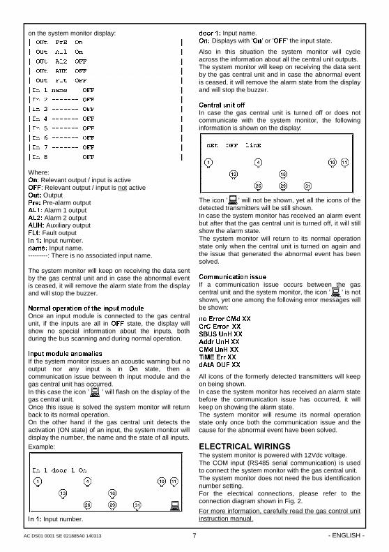
on the system monitor display: �
�28W��3U(��2Q������������������������� ��
�28W��$/���2Q������������������������� ��
�28W��$/���2))������������������������ ��
�28W��$8+��2))������������������������ ��
�28W��)/W��2))������������������������ ��
,Q���QDPH����2))���������������������� �������������������������
,Q�����������2))���������������������� �������������������������
,Q�����������2))���������������������� �������������������������
,Q�����������2))���������������������� �������������������������
,Q�����������2))���������������������� �������������������������
,Q�����������2))���������������������� �������������������������
,Q�����������2))���������������������� �������������������������
,Q�����������2))���������������������� ������������������������
Where: 2Q: Relevant output / input is active 2)): Relevant output / input is not active 2XW� Output 3UH� Pre-alarm output $/�� Alarm 1 output�$/�� Alarm 2 output�$8+� Auxiliary output�)/W� Fault output�,Q����Input number. QDPH� Input name. ---------: There is no associated input name.� The system monitor will keep on receiving the data sent by the gas central unit and in case the abnormal event is ceased, it will remove the alarm state from the display and will stop the buzzer. ��1RUPDO�RSHUDWLRQ�RI�WKH�LQSXW�PRGXOH�Once an input module is connected to the gas central unit, if the inputs are all in 2)) state, the display will show no special information about the inputs, both during the bus scanning and during normal operation. ,QSXW�PRGXOH�DQRPDOLHV�If the system monitor issues an acoustic warning but no output nor any input is in 2Q state, then a communication issue between th input module and the gas central unit has occurred. In this case the icon ’ ’ will flash on the display of the gas central unit. Once this issue is solved the system monitor will return back to its normal operation. On the other hand if the gas central unit detects the activation (ON state) of an input, the system monitor will display the number, the name and the state of all inputs.
Example:
�������������������������������������� �
�������������������������������������� �
,Q���GRRU���2Q������������������������ ������������������������
�������������������������������������� �
�������������������������������������� �
�������������������������������������� �
�������������������������������������� �
�������������������������������������� �
�������������������������������������� �
�
,Q����Input number.
GRRU��� Input name. 2Q��Displays with ’2Q’ or ’2))’ the input state.
Also in this situation the system monitor will cycle across the information about all the central unit outputs. The system monitor will keep on receiving the data sent by the gas central unit and in case the abnormal event is ceased, it will remove the alarm state from the display and will stop the buzzer. �&HQWUDO�XQLW�RII�In case the gas central unit is turned off or does not communicate with the system monitor, the following information is shown on the display:
�������������������������������������� �
�Q(W��2))��OLQ(����������������������� �
�������������������������������������� ���������
�������������������������������������� �
�������������������������������������� �
�������������������������������������� �
�������������������������������������� �
�������������������������������������� �
�������������������������������������� �
�
The icon ’ ’ will not be shown, yet all the icons of the detected transmitters will be still shown. In case the system monitor has received an alarm event but after that the gas central unit is turned off, it will still show the alarm state. The system monitor will return to its normal operation state only when the central unit is turned on again and the issue that generated the abnormal event has been solved. &RPPXQLFDWLRQ�LVVXH�If a communication issue occurs between the gas central unit and the system monitor, the icon ’ ’ is not shown, yet one among the following error messages will be shown:
QR�(UURU�&0G�;;�&U&�(UURU��;;�6%86�8Q+�;;�$GGU�8Q+�;;�&0G�8Q+�;;�7L0(�(UU�;;�G$W$�28)�;;�
All icons of the formerly detected transmitters will keep on being shown. In case the system monitor has received an alarm state before the communication issue has occurred, it will keep on showing the alarm state. The system monitor will resume its normal operation state only once both the communication issue and the cause for the abnormal event have been solved.
(/(&75,&$/�:,5,1*6�The system monitor is powered with 12Vdc voltage. The COM input (RS485 serial communication) is used to connect the system monitor with the gas central unit. The system monitor does not need the bus identification number setting. For the electrical connections, please refer to the connection diagram shown in Fig. 2.
For more information, carefully read the gas control unit instruction manual.
7

��������������
AC DS01 0001 SE 021885A0 140313 - ENGLISH -
����2KP�WHUPLQDWLRQ�UHVLVWRU��The termination devices on the RS485 bus (i.e. those devices which are wired at both ends of the RS485 bus - see examples shown in Fig. 3 and Fig. 4) must have enabled the internal 120 Ohm termination resistor. The termnation resistor located on the system monitor is activated by inserting the proper jumper on the connector -3�� �VHH� SRLQW� ��� LQ� WKH�SDUDJUDSK��,167$//$7,21��. 'R�QRW�DFWLYDWH�PRUH�WKDQ�WZR�WHUPLQDWLRQ�UHVLVWRUV�SHU�V\VWHP���
7(&+1,&$/�)($785(6�Power supply: 12V= ±10%. Absorption: 40 mA Communication protocol: S-Bus Protection rating: IP 30 Operating temp.: 0°C .. 40°C Storage temp.: -10°C .. +50°C Humidity limits: 20% .. 80% RH (non-condensing) Enclosure: Material: ABS V0 Self-extinguishing Colour: Signal white (RAL 9003) Dimensions: 156 x 108 x 47 mm (WxHxD) Weight: ~ 550 gr. 1250$7,9(�5()(5(1&(6�The product complies with the directives EMC 2004/108/EC and LVD 2006/95/EC.
,167$//$7,21�
72� ,167$//� 7+(� '(9,&(�� 3(5)250� 7+(�)2//2:,1*�23(5$7,216���
���Remove the central screw and the plastic door.
�� Remove the two screws shown in the drawing, then
remove the whole body from the base.
�� $66(0%/<�:,7+� &$%/(� ,1387� 21� 7+(� 5($5�
3$1(/�� if the cable fasteners (delivered with the unit) are not required for installation, use a screwdriver to remove the base blocks permitting the cables to pass through, and fit the blocks delivered.
�� Fix the power unit base to the wall. ���
8
130 130 mm
��������������
AC DS01 0001 SE 021885A0 140313 - ENGLISH -
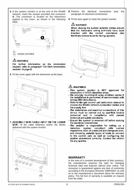
�� If the system monitor is at the end of the RS485 network, insert the Jumper provided into connector $. The connector is located on the electronics applied to the cover, as shown in the following table:
Jumper provided �
D�:$51,1*�
)RU� IXUWKHU� LQIRUPDWLRQ� RQ� WKH� WHUPLQDWLRQ�UHVLVWRU��UHIHU�WR�SDUDJUDSK�����2KP�WHUPLQDWLRQ�UHVLVWRU�DW�SDJH��� �
��� Fit the cover again with the electronics at the base. �����
�� $66(0%/<�:,7+�&$%/(�,1387�21�7+(�/2:(5�6,'(�� fit the cable fasteners and/or the blocks delivered with the system monitor.
�� Perform the electrical connections (see the paragraph on electrical connections).
�� Fit the door again to close the system monitor.
D�:$51,1*�
:KHQ�FORVLQJ� WKH�V\VWHP�PRQLWRU�SOHDVH�HQVXUH�WKDW� WKH� UHPRYDEOH� ZLULQJ� WHUPLQDOV� KDYH� EHHQ�LQVHUWHG� ZLWK� WKH� FRUUHFW� RULHQWDWLRQ� �WKH�WHUPLQDOV�VFUHZV�PXVW�EH�IDFLQJ�XSZDUG��
D�:$51,1*��� 7KLV� V\VWHP� PRQLWRU� LV� 127� DSSURYHG� IRU�LQVWDOODWLRQ�LQ�$7(;�FODVVLILHG�DUHDV��
�� :H� VWURQJO\� UHFRPPHQG� XVLQJ� VKLHOGHG� FDEOHV� LI�WKH�LQVWDOODWLRQ�LV�SHUIRUPHG�LQ�HQYLURQPHQWV�ZLWK�VWURQJ�(0&�GLVWXUEDQFH��
�� 5HIHU�WR�WKH�JDV�FRQWURO�XQLW�LQVWUXFWLRQ�PDQXDO�WR�FKRRVH�WKH�56����QHWZRUN�FRQQHFWLRQ�FDEOHV�DQG�WKH�VXSSO\�OLQH��
�� 7KH� LQVWDOODWLRQ�DQG�HOHFWULFDO�FRQQHFWLRQV�RI� WKLV�GHYLFH� PXVW� EH� FDUULHG� RXW� E\� TXDOLILHG� WHFQLFD�SHUVRQQHO� DQG� LQ� FRPSOLDQFH� ZLWK� FXUUHQW�WHFKQLFDO�DQG�VDIHW\�VWDQGDUGV��
�� (QVXUH� WKH� V\VWHP� LV� SRZHUHG� RII� EHIRUH�PDNLQJ�WKH�HOHFWULFDO�FRQQHFWLRQV��
�� 7KH� LQVWDOOHU� LV� UHVSRQVLEOH� IRU� VHWWLQJ� XS� D�GHWHFWLRQ� V\VWHP� FRPSOLDQW� ZLWK� FXUUHQW�UHJXODWLRQV��ERWK�DW�D�QDWLRQDO�DQG�(XURSHDQ�OHYHO��DQG� FKRRVLQJ� VXLWDEOH� W\SHV� RI� ORDGV� WR� FRQQHFW�WR� WKH� FRQWURO� XQLW�� DV� ZHOO� DV� FRQILJXULQJ� WKH�V\VWHP�SDUDPHWHUV� FRUUHFWO\��&RQWDFW� WKH� UHWDLOHU�IRU�DQ\�TXHULHV��
����
�:$55$17<�In the view of a constant development of their products, the manufacturer reserves the right for changing technical data and features without prior notice. The consumer is guaranteed against any lack of conformity according to the European Directive 1999/44/EC as well as to the manufacturer’s document about the warranty policy. The full text of warranty is available on request from the seller.
9
$
��������������
AC DS01 0001 SE 021885A0 140313 - ENGLISH - 10
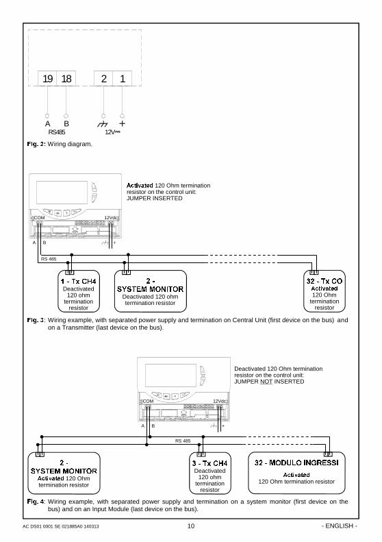
)LJ���: Wiring example, with separated power supply and termination on Central Unit (first device on the bus) and on a Transmitter (last device on the bus).
�����7[�&2�$FWLYDWHG 120 Ohm
termination resistor
A B
RS 485
+
COM 12Vdc
$FWLYDWHG 120 Ohm termination resistor on the control unit: JUMPER INSERTED
����7[�&+��Deactivated
120 ohm termination
resistor
����6<67(0�021,725�
Deactivated 120 ohm termination resistor
)LJ���: Wiring example, with separated power supply and termination on a system monitor (first device on the bus) and on an Input Module (last device on the bus).
A B
RS 485
+
COM 12Vdc
Deactivated 120 Ohm termination resistor on the control unit: JUMPER NOT INSERTED
����7[�&+��Deactivated
120 ohm termination
resistor
����6<67(0�021,725�
$FWLYDWHG 120 Ohm termination resistor
�����02'8/2�,1*5(66,�
$FWLYDWHG 120 Ohm termination resistor
1819 2 1
12VRS485BA
)LJ�����Wiring diagram.�

