vacuum insulation for windows - energy
TRANSCRIPT

Lin Simpson, [email protected] National Renewable Energy Laboratory
Vacuum Insulation for Windows 2014 Building Technologies Office Peer Review
Picture of NREL’s
transparent vacuum
insulation for windows.
The picture
demonstrates that the
evacuated components
are transparent while
providing superior
insulation in a flexible
structure that can be
retrofitted to installed
windows.

2
Project Summary
New Competively Selected Award FOA 823 Initial TRL: laboratory validation and development
Timeline: Start date: October 1, 2013 Planned end date: September 30, 2015 Key Milestones 1. Assess vacuum insulation materials with less
than 0.007 W/m-K thermal conductivity; September 30, 2014
2. Deliver VI with low-e for external testing; September 30, 2015
Budget: Total DOE $ to date: $375,000 FY14
Total future DOE $: $375,000 FY15
Key Partners: Have begun discussions with commercial companies that can provide key strategic alliances for manufacturing and specific market applications. Partners to include vacuum capsule, low-e film, and window manufacturers.
Key milestone at end of year one is to have a commercial partner(s)
Project Goal: This effort is assessing the impact vacuum insulation (VI) will have for window applications using novel evacuated materials (that are so small as to be invisible) integrated with low-e coated plastic films. The ultimate goal is to develop materials that have R-10 to R-20 insulation values and have the correct form factor for easy integration with installed windows (i.e., flexible, thin, and applied like tinting products).
Target Market/Audience: This effort addresses the large installed windows retrofit and inexpensive high performing new windows markets to substantially improve fenestration and building envelope energy efficiency.

3
Purpose and Objectives
• Problem Statement: Buildings use ~40% of the energy and produce ~40% of the CO2 emissions in the United States (US) today.
– Windows can account for 30% to 50% of the energy losses in buildings. • It could take decades and trillions of dollars before replaced with highly insulating windows. • Thus substantial need for retrofitting installed windows to improve energy efficiency.
– This effort is assessing vacuum insulation (VI) for window applications using novel evacuated materials (that are so small as to be invisible) integrated with low-e coated plastic films.
– Goal: develop R-10 to R-20 insulation that has the correct form factor for easy integration with installed windows (i.e., flexible, thin, and applied like tinting products).
• Target Market and Audience: This effort addresses the large installed windows retrofit and inexpensive high performing new windows markets to substantially improve fenestration and building envelope energy efficiency.
– Could save 1 to 3 quads of energy annually in US.
• Impact of Project: The project creates R-10 to R-20 transparent VI films that utilize nano- to micrometer sized vacuum capsules integrated with standard low-e coated flexible window plastics.
– Near-term impact path: quantify insulation, transparency, cost, and other performance criteria to identify high-value market opportunities to support initial transition to commercial products.
– Intermediate-term impact path: Work with commercialization partners to optimize performance for specific applications
– Long-term impact path: Work with commercial and residential building communities to develop rapid market penetration strategies to help decrease energy use and CO2 emissions as quickly as possible

4
Approach • Use basic processes and materials to form smooth vacuum capsule layers with structure that
minimizes thermal conductivity
• Maintain most of the properties typically associated with thin flexible plastic sheets used for applications like tinting.
– Inexpensive and scalable to high throughput, such as the production lines at plastics and insulation manufacturing companies.
• Work with companies to identify and measure vacuum capsules that have the light transmission, strength, and evacuation/vacuum properties needed for VI.
– When possible, use commercially available materials and low-e coated films from retail suppliers.
• Assess vacuum capsule materials insulation properties better.
– With low-e coated films, create transparent R-10 to R-20 films
Key Issues: Thermal conductivity measurements below 20 mW/m-K
Distinctive Characteristics: Highly insulating transparent film will be a game changer for windows, resulting in substantial energy and CO2 reductions

5
Progress and Accomplishments: Measurements • Improved flash system sensitivity
o Can measure small thin samples typical of initial R&D – IR camera and analyzing full time dependence of heat
transport improves accuracy – Does not require heat capacity measurements – Demonstrated that IR camera easily monitors heating from
edges, and that edge heating was not an issue – Independent of sample or measurement area and intensity – Accurate for cork and plexi-glass thermal conductivity
For these samples with t ≤ 12 mm, diffusivity is unaffected by edge effects
Hot
edges
(r =
30 m
m)
Cold
Edges
(r =
24 m
m)
3.0
2.5
2.0
1.5
1.0
0.5
0.0Te
mp
era
ture
In
cre
ase
(C
)
6040200
time (s)
r = 30 mm r = 28 mm r = 26 mm r = 24 mm
Intentionally introducing edge effects by varying the aperture size
1.20
1.15
1.10
1.05
1.00
Th
erm
al D
iffu
siv
ity (
mm
2/s
)
30292827262524
Aperture Radius (mm)

6
Progress and Accomplishments: Measurements • Two main issues have limited accurate measurements for low TC materials.
o Highly porous materials appear to be IR transparent o Need to correctly account for multiple interfaces
• For rigid materials, TC measurements good to less than 70 mW/m-K • TC measurements not good for porous materials
o Foam insulation o Aerogels, vacuum capsules, or vacuum in general o Preliminary results agree with literature that vacuum capsules may be substantially better
insulation than foams
Table of Thermal Transport Values

7
Progress and Accomplishments: Measurements • For calibration, will
need to go to aerogels and evacuated samples to get materials with low enough thermal conductivities
Bouquerel, et. al., Proceedings of Building Simulation, Sydney, 1973 (2011).
http://web.mae.ufl.edu/tribology/Courses/MessageBoard/Fluids/messages/chart9.jpg

8
Highly Insulating Transparent Fenestration Testing
• Ultimately need to perform ASTM standards to compare VI with other products
• ASTM Standard C1199 − 12 “Standard Test Method for Measuring the Steady-
State Thermal Transmittance of Fenestration Systems Using Hot Box Methods”
on Transparent Vacuum Materials in system.
• ASTM Standard ASTM C1363 – 11: “Standard Test Method for Thermal
Performance of Building Materials and Envelope Assemblies by Means of a Hot
Box Apparatus”
• May purchase commercial Hot Plate system to perform initial TC measurements • Main problem requires 30 cm X 30 cm x 1 cm sample sizes
Heat Flow Meter or Hot Plate, eventually NTS Differential Thermal Cycling Unit (DTCU)
9
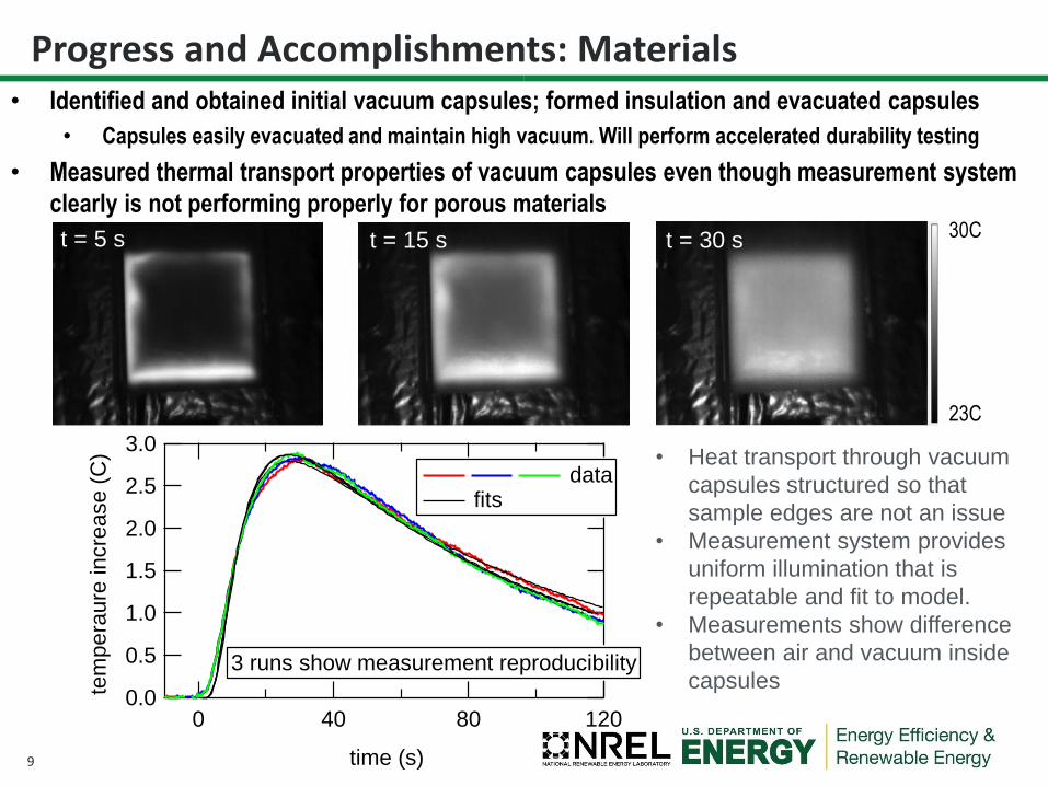
Progress and Accomplishments: Materials
t = 5 s
• Identified and obtained initial vacuum capsules; formed insulation and evacuated capsules
• Capsules easily evacuated and maintain high vacuum. Will perform accelerated durability testing
• Measured thermal transport properties of vacuum capsules even though measurement system
clearly is not performing properly for porous materials
3.0
2.5
2.0
1.5
1.0
0.5
0.0tem
pe
raure
incre
ase (
C)
12080400
time (s)
data fits
3 runs show measurement reproducibility
30C
23C
t = 15 s t = 30 s
• Heat transport through vacuum
capsules structured so that
sample edges are not an issue
• Measurement system provides
uniform illumination that is
repeatable and fit to model.
• Measurements show difference
between air and vacuum inside
capsules

10
Materials: Pressure Dependence
• From literature, with air inside capsules, the thermal conductivity decreases from ~20 mW/m-K at atmospheric pressure to ~0.6 mW/m-K at ~1 mtorr for pressures outside capsule
• Because most of the volume is inside the capsule; when evacuated, should see a similar type of thermal conductivity decrease, even with air on the outside of the capsule
– Preliminary results: evacuated capsules shows some decrease in thermal conductivity
• Measurements are not accurate.
– The measured aerogel results are more than a factor of 2 higher than expected.
Preliminary data suggest that with accurate measurements, evacuated capsules may have lower thermal conductivity values than evacuated aerogels.

11
Materials: Lower Thermal Conductivity • 3 main strategies to improve NREL’s transparent insulation
o Evacuate vacuum capsules which accounts for majority of volume
o Minimize amount and size of spaces outside capsules
o Minimize radiation heat transport with low-e coatings
• Achieve thermal conductivities between 0.2 and 5 mW/m-K
www.oboa.on.ca/events/2010/sessions/files/710.pdf
k k
Thermal Conductivity Contributions in Aerogels

12
Progress and Accomplishments: Processing
• Capsule Functionalization and Assembly – Identified and tested initial vacuum capsule
layer integration methods from literature to create suspensions that work
• Note: after 24 hr some capsules settle to bottom
• Suspension sufficient for different deposition techniques, including dip and lamination
– These same techniques provide excellent stacking of vacuum capsules to form high quality optical coatings with limited voids
• Limited stacking voids important
• Use different suspension materials to tailor processes from transparency and insulation
Images of vacuum capsule suspensions right
after mixing and 24 hours later
Image of vacuum capsules in water
(4 mg/ml) used for dip coating Image of Vacuum Capsules Deposited using Dip
Coating, demonstrating virtually no visual degradation. Single dip had ~75% coverage of
~100 nm thick layer

13
Progress and Accomplishments: Energy Savings Analysis
Completed initial energy savings and cost per energy saved analyses
• Apply technology to DOE commercial reference building energy models
– Standard reference models provide a common set of inputs
• 16 building types and 16 locations
• Three sets of buildings – New construction – 90.1-2004
– Post-1980 construction (~90.1-1989)
– Pre-1980 construction (pre energy standards)
• Simulate models with and without technology in each location to provide savings potential values
• Apply factors that characterize the number of buildings that are similar to each reference building in each location to quantify impact potential
14
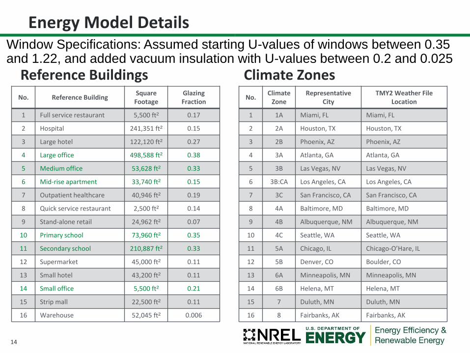
Energy Model Details
No. Reference Building Square
Footage Glazing Fraction
1 Full service restaurant 5,500 ft² 0.17
2 Hospital 241,351 ft² 0.15
3 Large hotel 122,120 ft² 0.27
4 Large office 498,588 ft² 0.38
5 Medium office 53,628 ft² 0.33
6 Mid-rise apartment 33,740 ft² 0.15
7 Outpatient healthcare 40,946 ft² 0.19
8 Quick service restaurant 2,500 ft² 0.14
9 Stand-alone retail 24,962 ft² 0.07
10 Primary school 73,960 ft² 0.35
11 Secondary school 210,887 ft² 0.33
12 Supermarket 45,000 ft² 0.11
13 Small hotel 43,200 ft² 0.11
14 Small office 5,500 ft² 0.21
15 Strip mall 22,500 ft² 0.11
16 Warehouse 52,045 ft² 0.006
No. Climate
Zone Representative
City TMY2 Weather File
Location
1 1A Miami, FL Miami, FL
2 2A Houston, TX Houston, TX
3 2B Phoenix, AZ Phoenix, AZ
4 3A Atlanta, GA Atlanta, GA
5 3B Las Vegas, NV Las Vegas, NV
6 3B:CA Los Angeles, CA Los Angeles, CA
7 3C San Francisco, CA San Francisco, CA
8 4A Baltimore, MD Baltimore, MD
9 4B Albuquerque, NM Albuquerque, NM
10 4C Seattle, WA Seattle, WA
11 5A Chicago, IL Chicago-O’Hare, IL
12 5B Denver, CO Boulder, CO
13 6A Minneapolis, MN Minneapolis, MN
14 6B Helena, MT Helena, MT
15 7 Duluth, MN Duluth, MN
16 8 Fairbanks, AK Fairbanks, AK
Reference Buildings Climate Zones
Window Specifications: Assumed starting U-values of windows between 0.35 and 1.22, and added vacuum insulation with U-values between 0.2 and 0.025

15
Energy Modeling: Example of Results
• Average energy savings from baseline for all commercial building types in all environments is between 2.5% and 5% for U values between 0.2 and 0.025 – These values even include
“warehouse” structures with very few windows.
• However, even U-0.2 can save ~19% for some buildings in some climates. – This increases to ~23% for U-0.025
• These energy savings translate to as much as 12% reductions in costs.
Pre-1980 Large Office
Pre-1980 Large Office
16
Progress and Accomplishments: Summary • Vacuum capsule selection and characterization
– Identified/obtained initial vacuum capsules, formed insulation with evacuated capsules – Performed initial thermal conductivity measurements and determined that the thermal
conductivity was substantially lower than ~R-13 insulation board.
• Began investigating optical properties of vacuum capsules. • Identified and tested initial vacuum capsule layer integration
– This initial process is compatible with dip-coating, spray, casting, and/or lamination type techniques to form initial insulation samples.
• Characterized thermal properties of vacuum insulation samples. – Characterized initial VI samples and measured insulation values. – Improved NREL’s in-house thermal conductivity measurements and determined lower accuracy
limit; presently at ~70 mW/m-K. – Procuring commercial thermal conductivity measurement system with 2 mW/m-K accuracy
• Performed initial Energy Modeling – Completed initial energy savings & cost per energy saved analyses assuming VI ultimate
performance – Performed initial building energy modeling to show performance metrics
• Intellectual Property – Reviewed literature, completed IP portfolio evaluation and submitted initial provisional patent – Due to the early stage development nature of work, some details constrained due to IP concerns
• Tech Transfer/Commercialization – Had initial discussions with material and end user companies

17
Project Integration: • Work with NREL’s commercial, residential, emerging technology, and technology transfer
buildings groups that have substantial experience and contacts within the buildings community including potential commercialization partners.
• As project progresses and performance is quantified, more industrial collaborators and partners will be engaged to help guide development and identify specific market applications.
Partners, Subcontractors, and Collaborators: • Continue discussions and work with commercial companies to form key strategic
manufacturing and market alliances. • Partners to include vacuum capsule, low-e film, and window manufacturers. • Specific partners will be identified once more formal arrangements and permissions
have been obtained.
Communications: • New competitively awarded project and this review meeting is the first public presentation of
some of the technology. • Future presentations at conferences, workshops, and review meeting is anticipated.
Project Integration and Collaboration

18
Next Steps and Future Plans
• Continue developing new inexpensive transparent vacuum insulation to substantially improve the R-values of windows. – Finalize present thermal conductivity measurement system capabilities and
determine if other instrument is needed
• Determined upper insulation value limit of vacuum capsules
– Continue investigating optical properties of vacuum capsules
• Identify potential performance to help guide market analysis
– Improve integration processes to form well-ordered vacuum capsule layers
• Enhance performance while reducing costs
– Perform additional Energy Modeling
• Determine best configurations and high value applications
– Hold more discussions with potential commercialization partners
• Work with selected partners to identify commercialization paths for first adopter markets and value propositions

19
Acknowledgements (Many People Providing Expertise)
• Michele Olsen and Phil Parilla: Thermal Conductivity Measurements
• Chaiwat Engtrakul and Robert Tenent: Coatings
• Tim Snow and Chaiwat Engtrakul: Durability and Reliability
• Eric Bonnema: Energy Performance Modeling and Cost Analysis
• Ty Ferretti and LaNelle Owens: Intellectual Property
• Yoriko Morita: Tech Transfer/Commercialization:
• Pat Phelan and Karma Sawyer: DOE Emerging Technology
• Leon Fabick and Craig Livorsi: DOE Golden Field Office

20
REFERENCE SLIDES

21
Project Budget: $375,000 in FY14 and $375,000 in FY15 Variances: NA Cost to Date: ~$180,000 or ~50% Additional Funding: NA
Budget History
FY2013 (past)
10/1/2014 - FY2014 (current)
FY2015 – Insert End Date (planned)
DOE Cost-share DOE Cost-share DOE Cost-share $375,000 $0 $375,000 $0
Project Budget (New Project Started in FY2014)

22
Project Plan and Schedule
2013